US10724229B2 - Slip clip - Google Patents
Slip clipDownload PDFInfo
- Publication number
- US10724229B2 US10724229B2US15/694,623US201715694623AUS10724229B2US 10724229 B2US10724229 B2US 10724229B2US 201715694623 AUS201715694623 AUS 201715694623AUS 10724229 B2US10724229 B2US 10724229B2
- Authority
- US
- United States
- Prior art keywords
- structural member
- plate
- fastener
- elongated
- structural
- Prior art date
- Legal status (The legal status is an assumption and is not a legal conclusion. Google has not performed a legal analysis and makes no representation as to the accuracy of the status listed.)
- Active
Links
Images


Classifications
- E04B1/40—
- E—FIXED CONSTRUCTIONS
- E04—BUILDING
- E04B—GENERAL BUILDING CONSTRUCTIONS; WALLS, e.g. PARTITIONS; ROOFS; FLOORS; CEILINGS; INSULATION OR OTHER PROTECTION OF BUILDINGS
- E04B1/00—Constructions in general; Structures which are not restricted either to walls, e.g. partitions, or floors or ceilings or roofs
- E04B1/38—Connections for building structures in general
- E04B1/388—Separate connecting elements
- E—FIXED CONSTRUCTIONS
- E04—BUILDING
- E04B—GENERAL BUILDING CONSTRUCTIONS; WALLS, e.g. PARTITIONS; ROOFS; FLOORS; CEILINGS; INSULATION OR OTHER PROTECTION OF BUILDINGS
- E04B1/00—Constructions in general; Structures which are not restricted either to walls, e.g. partitions, or floors or ceilings or roofs
- E04B1/18—Structures comprising elongated load-supporting parts, e.g. columns, girders, skeletons
- E04B1/24—Structures comprising elongated load-supporting parts, e.g. columns, girders, skeletons the supporting parts consisting of metal
- E04B1/2403—Connection details of the elongated load-supporting parts
- E—FIXED CONSTRUCTIONS
- E04—BUILDING
- E04B—GENERAL BUILDING CONSTRUCTIONS; WALLS, e.g. PARTITIONS; ROOFS; FLOORS; CEILINGS; INSULATION OR OTHER PROTECTION OF BUILDINGS
- E04B1/00—Constructions in general; Structures which are not restricted either to walls, e.g. partitions, or floors or ceilings or roofs
- E04B1/18—Structures comprising elongated load-supporting parts, e.g. columns, girders, skeletons
- E04B1/26—Structures comprising elongated load-supporting parts, e.g. columns, girders, skeletons the supporting parts consisting of wood
- E04B1/2604—Connections specially adapted therefor
- E04B1/2608—Connectors made from folded sheet metal
- E—FIXED CONSTRUCTIONS
- E04—BUILDING
- E04B—GENERAL BUILDING CONSTRUCTIONS; WALLS, e.g. PARTITIONS; ROOFS; FLOORS; CEILINGS; INSULATION OR OTHER PROTECTION OF BUILDINGS
- E04B2/00—Walls, e.g. partitions, for buildings; Wall construction with regard to insulation; Connections specially adapted to walls
- E04B2/74—Removable non-load-bearing partitions; Partitions with a free upper edge
- E04B2/76—Removable non-load-bearing partitions; Partitions with a free upper edge with framework or posts of metal
- E04B2/766—T-connections
- E04B2/767—Connections between wall studs and upper or lower locating rails
- E04B2/768—Connections between wall studs and upper or lower locating rails allowing vertical movement of upper rail with respect to the stud, e.g. by using slots in the rail or stud
- E—FIXED CONSTRUCTIONS
- E04—BUILDING
- E04B—GENERAL BUILDING CONSTRUCTIONS; WALLS, e.g. PARTITIONS; ROOFS; FLOORS; CEILINGS; INSULATION OR OTHER PROTECTION OF BUILDINGS
- E04B1/00—Constructions in general; Structures which are not restricted either to walls, e.g. partitions, or floors or ceilings or roofs
- E04B1/18—Structures comprising elongated load-supporting parts, e.g. columns, girders, skeletons
- E04B1/24—Structures comprising elongated load-supporting parts, e.g. columns, girders, skeletons the supporting parts consisting of metal
- E04B1/2403—Connection details of the elongated load-supporting parts
- E04B2001/2415—Brackets, gussets, joining plates
- E—FIXED CONSTRUCTIONS
- E04—BUILDING
- E04B—GENERAL BUILDING CONSTRUCTIONS; WALLS, e.g. PARTITIONS; ROOFS; FLOORS; CEILINGS; INSULATION OR OTHER PROTECTION OF BUILDINGS
- E04B1/00—Constructions in general; Structures which are not restricted either to walls, e.g. partitions, or floors or ceilings or roofs
- E04B1/18—Structures comprising elongated load-supporting parts, e.g. columns, girders, skeletons
- E04B1/24—Structures comprising elongated load-supporting parts, e.g. columns, girders, skeletons the supporting parts consisting of metal
- E04B1/2403—Connection details of the elongated load-supporting parts
- E04B2001/2439—Adjustable connections, e.g. using elongated slots or threaded adjustment elements
- E—FIXED CONSTRUCTIONS
- E04—BUILDING
- E04B—GENERAL BUILDING CONSTRUCTIONS; WALLS, e.g. PARTITIONS; ROOFS; FLOORS; CEILINGS; INSULATION OR OTHER PROTECTION OF BUILDINGS
- E04B1/00—Constructions in general; Structures which are not restricted either to walls, e.g. partitions, or floors or ceilings or roofs
- E04B1/18—Structures comprising elongated load-supporting parts, e.g. columns, girders, skeletons
- E04B1/24—Structures comprising elongated load-supporting parts, e.g. columns, girders, skeletons the supporting parts consisting of metal
- E04B1/2403—Connection details of the elongated load-supporting parts
- E04B2001/2448—Connections between open section profiles
- E—FIXED CONSTRUCTIONS
- E04—BUILDING
- E04B—GENERAL BUILDING CONSTRUCTIONS; WALLS, e.g. PARTITIONS; ROOFS; FLOORS; CEILINGS; INSULATION OR OTHER PROTECTION OF BUILDINGS
- E04B1/00—Constructions in general; Structures which are not restricted either to walls, e.g. partitions, or floors or ceilings or roofs
- E04B1/38—Connections for building structures in general
- E04B1/388—Separate connecting elements
- E04B2001/389—Brackets
- E04B2001/405—
- F—MECHANICAL ENGINEERING; LIGHTING; HEATING; WEAPONS; BLASTING
- F16—ENGINEERING ELEMENTS AND UNITS; GENERAL MEASURES FOR PRODUCING AND MAINTAINING EFFECTIVE FUNCTIONING OF MACHINES OR INSTALLATIONS; THERMAL INSULATION IN GENERAL
- F16B—DEVICES FOR FASTENING OR SECURING CONSTRUCTIONAL ELEMENTS OR MACHINE PARTS TOGETHER, e.g. NAILS, BOLTS, CIRCLIPS, CLAMPS, CLIPS OR WEDGES; JOINTS OR JOINTING
- F16B37/00—Nuts or like thread-engaging members
- F16B37/08—Quickly-detachable or mountable nuts, e.g. consisting of two or more parts; Nuts movable along the bolt after tilting the nut
- F16B37/0807—Nuts engaged from the end of the bolt, e.g. axially slidable nuts
- F16B37/0842—Nuts engaged from the end of the bolt, e.g. axially slidable nuts fastened to the threaded bolt with snap-on-action, e.g. push-on nuts for stud bolts
- F—MECHANICAL ENGINEERING; LIGHTING; HEATING; WEAPONS; BLASTING
- F16—ENGINEERING ELEMENTS AND UNITS; GENERAL MEASURES FOR PRODUCING AND MAINTAINING EFFECTIVE FUNCTIONING OF MACHINES OR INSTALLATIONS; THERMAL INSULATION IN GENERAL
- F16B—DEVICES FOR FASTENING OR SECURING CONSTRUCTIONAL ELEMENTS OR MACHINE PARTS TOGETHER, e.g. NAILS, BOLTS, CIRCLIPS, CLAMPS, CLIPS OR WEDGES; JOINTS OR JOINTING
- F16B39/00—Locking of screws, bolts or nuts
- F16B39/02—Locking of screws, bolts or nuts in which the locking takes place after screwing down
- F16B39/10—Locking of screws, bolts or nuts in which the locking takes place after screwing down by a plate, spring, wire or ring immovable with regard to the bolt or object and mainly perpendicular to the axis of the bolt
Definitions
- the present inventionbelongs to a class of stud mounting clips that are useful in the construction of buildings, particularly light commercial buildings.
- Exterior walls and framesare often made from materials that have different coefficients of expansion than that of the structure's exterior sheathing. Exposure to extreme temperatures can produce gaps in the exterior sheathing if the panels expand or contract more than the framing. Gaps allow cold air and moisture to intrude.
- Exterior walls of buildingsare also subject to deflection from wind or seismic forces, and a degree of freedom of movement can reduce stress and prevent fracture of connected parts.
- curtain wallsare not designed to support vertical loads and must therefore by isolated from deflection of the primary load-bearing support structure of the building due to changes in live or dead loads carried by that structure.
- the slip clip connector of the present inventionhas been designed to achieve strong load values while being inexpensive to manufacture.
- the present inventionfocuses on the fasteners anchoring the connector to the vertical member to improve the performance of the connection.
- the present inventionprovides a connection between a first structural member and a second structural member by means of an angled connector having first and second plates joined at an angled juncture.
- the first plateis connected to the first structural member.
- the second plateis joined to the second structural member by a plurality of fastenings that allow the second structural member to move relative to the first structural member a selected distance.
- the fastening of the angled connector to the second structural member closest to the angled junctureis reinforced.
- the present inventionprovides an angled connector having elongated slots where the fastenings between the second structural member and the angled connector are formed.
- the present inventionprovides an angled connector having a plurality of elongated slots for connecting the second plate to the second structural member and the elongated slot closest to the juncture between the plates of the angled connector is dimensioned allow for the use of multiple fasteners in this slot while still providing the designed—for freedom of movement between the first and second structural members.
- the elongated slot closest to the juncturecan be bracketed by strengthening deformations in the plate that contains the slot.
- the strengthening deformationsare embossments.
- the elongated slotsare of equal width.
- the present inventionalso provides an angled connector where the one or more of the fasteners used to connect the connector to the vertical member is provided with a nut, weld or other lock member on the side of the fastener opposed to the head of the fastener to serve as a stop.
- the fastener closest to the juncture in the angle connectoris reinforced by providing a washer between the head of the fastener and the second plate of the connector where the washer is an elongated member that also is disposed between the head of at least one more fastener and the second plate.
- the angled connector of the present inventionis made from light-gauge steel.
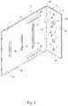
- FIG. 1is a perspective view of one embodiment of the connector of the present invention.
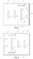
- FIG. 2is a front view of the connector of FIG. 1 .
- FIG. 3is a back view of the connector of FIG. 1 .
- FIG. 4is left side view of the connector of FIG. 1 .
- FIG. 5is a right side view of the connector of FIG. 1 .
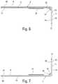
- FIG. 6is a top view of the connector of FIG. 1 .
- FIG. 7is a bottom view of the connector of FIG. 1 .
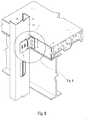
- FIG. 8is a perspective view of a wall stud to floor member connection formed according to the present invention.
- FIG. 9is a close-up perspective view of the connection of FIG. 8 .
- FIG. 10is a top view of the connection shown in FIG. 8 .
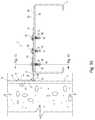
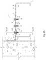
- FIG. 11is a cross-sectional side view of the connection shown in FIG. 8 .
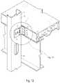
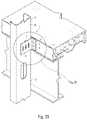
- FIG. 12is a perspective view of a wall stud to floor member connection formed according to the present invention.
- FIG. 13is a close-up perspective view of the connection of FIG. 12 .
- FIG. 14is a top view of the connection shown in FIG. 12 .
- FIG. 15is a cross-sectional side view of the connection shown in FIG. 12 .
- FIG. 16is a perspective view of one embodiment of the connector of the present invention.
- FIG. 17is a front view of the connector of FIG. 16 .
- FIG. 18is a back view of the connector of FIG. 16 .
- FIG. 19is left side view of the connector of FIG. 16 .
- FIG. 20is a right side view of the connector of FIG. 16 .
- FIG. 21is a top view of the connector of FIG. 16 .
- FIG. 22is a bottom view of the connector of FIG. 16 .
- FIG. 23is a perspective view of a wall stud to floor member connection formed according to the present invention.
- FIG. 24is a close-up perspective view of the connection of FIG. 23 .
- FIG. 25is a top view of the connection shown in FIG. 23 .
- FIG. 26is a cross-sectional side view of the connection shown in FIG. 23 .
- FIG. 27is a top view of a connection formed according to the present invention, showing a weld applied to one of the fasteners.
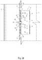
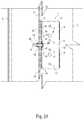
- FIG. 28is a cross-sectional side view of the connection shown in FIG. 27 .
- FIG. 29is a perspective view of a wall stud to floor member connection formed according to the present invention.
- FIG. 30is a close-up perspective view of the connection of FIG. 29 .
- FIG. 31is a perspective view of the washer used in the connection of FIG. 29 .
- FIG. 32is a top view of the connection shown in FIG. 29 .
- FIG. 33is a cross-sectional side view of the connection shown in FIG. 29 .
- FIG. 34is a perspective view of a wall stud to floor member connection formed according to the present invention.
- FIG. 35is a close-up perspective view of the connection of FIG. 34 .
- FIG. 36is a top view of the connection shown in FIG. 34 .
- FIG. 37is a cross-sectional side view of the connection shown in FIG. 34 .
- the present inventionis a building structural connection 1 between a first structural member 2 and a second structural member 3 .
- the first structural member 2is a supporting member 2 and the second structural member 3 is a supported structural member 3 .
- the first structural member 2is a floor member that is horizontally disposed 2 with an attached ledger and the second structural member 3 is a vertically-oriented channel-shaped wall post or stud 3 that is part of a wall.
- the connection 1 between the first structural member 2 and the second structural member 3is made with a first angled connector 4 .
- the first angled connector 4is preferably L-shaped, with a first plate 5 fastened to the first building structural member 2 and a second plate 6 fastened to the second building structural member 3 .
- the first plate 5 and the second plate 6are generally planar and joined at right angles to each other.
- the connector 4allows for relative vertical movement between the first and second building structural members 2 and 3 .
- the connector 4is preferably made from cold formed sheet steel, bent, cut, embossed and punched on automated manufacturing machinery.
- the first plate 5has first and second fastener openings 7 and 8 .
- Fastener openings 8are larger than fastener openings 7 to accommodate larger fasteners.
- the angled connector 4 shown in FIG. 8is attached to the second structural member by welds 9 .
- the first plate 5has a first inner edge 11 , a first outer edge 12 , a first side edge 13 and a second side edge 14 .
- the second plate 6has a plurality of fastener openings 15 formed as elongated slots.
- the second plate 6is also provided with a first inner edge 16 , a first side edge 17 and a second side edge 18 .
- the first inner edge 11 of the first plate 5is joined to the first inner edge 16 of the second plate 6 to form an inner angular juncture 19 .
- the inner angular juncture 19is 90 degrees.
- One of the slotted openings 10lies closer to the juncture 19 than the other slotted openings.
- the slotted openings 15are preferably disposed parallel to the angular juncture 19 between the first plate 5 and the second plate 6 .
- Each elongated slot 15 in the second plate 6is a site of a fastening to the second structural member 3 .
- a first reinforcing deformation or embossment 20is provided parallel to the first side edge 17 of the second plate 6 .
- a second reinforcing deformation or embossment 21is provided parallel to the second side edge 18 of the second plate 6 .
- the first and second reinforcing embossments 20 and 21preferably extend orthogonally to the elongated slotted openings 15 in the second plate 6 . Preferably, they are disposed adjacent and to either side of the nearest slotted opening 10 to the angular juncture 19 .
- the emobssments 20 and 21extend past the lateral sides of the elongated opening 10 and are disposed away from the side edges 17 and 18 .
- the connector 4includes a plurality of gusset darts 26 having a substantially triangular shape when viewed from a lateral side thereof, the substantially triangular shaped gusset darts 26 are disposed in the inner angular juncture 19 between the plates 5 and 6 .
- the gusset darts 26preferably have a substantially u-shaped cross-section. The gusset darts 26 reinforce the inner angular juncture 19 .
- a first plurality of fasteners 27attaches the first plate 5 to the first building structural member 2 .
- the fastenes 27can be welds, but anchors and screws received in the fastener openings 7 and 8 are also preferred.
- a plurality of fasteners 28preferably attaches the second plate 6 to the second building structural member 3 .
- the fasteners 28 that attach the second plate to the second structural memberare screws 28 of similar dimensions.
- the preferred fasteners 27 for attaching the connector 4 to first structural member 2 made from steelare hex-head fasteners 27 , automated power-actuated gun-driven fasteners 27 or, alternatively, welds 27 .
- the preferred fasteners 27 for attaching the connector 4 to first structural members 2 made from concreteare concrete screws 27 .
- the preferred fasteners 28 for attaching the connector 4 through slots 15are shouldered, or stepped-shank, self-drilling screws 28 .
- the second plurality of fastener openings 15is preferably formed as a plurality of elongated slots 15 in the second plate 6 as movement between the structural member 3 and the connector 4 is desired.
- the fastener 28is drilled into or connected to the stud or second structural member 3 , the fastener is anchored in the stud 3 .
- the fastener 28moves in the elongated slots 15 .
- the first building structural member 2is fastened to the first connector 4 so that the first building structural member 2 cannot move relative the first plate 5 of the first connector 4 .
- the second building structural member 3is preferably fastened to the first connector 4 so that the second building structural member 3 can move relative to the second plate 6 of the first connector 4 .
- the plurality of elongated slot openings 15 that extend across the second plate 6extend generally parallel to the inner angular juncture 19 between the first plate 5 and the second plate 6 .
- the fasteners of the second plurality of fasteners 28are shouldered, or stepped-shank screws 28 .
- Shouldered screws 28have a head 29 , an unthreaded shank portion 30 immediately below the head 29 , a threaded shank portion 31 below the unthreaded shank portion 30 , and a tip 32 .
- the tipis preferably a self-drilling tip.
- the unthreaded shank portion 30allows the second building structural member 3 and the fasteners 28 attached to it to move relative to the second plate 6 without interference between the second plurality of fastener 28 and the second plate 6 of the first connector 4 .
- the tip 32is designed to drill itself into the web 33 of the stud 3 .
- the web 33 of the studis preferably a substantially planar member.
- Each elongated slot 15 in said second plate 6is a site of a fastening to the second structural member 3 , and each elongated slot 15 receives at least one fastener 28 having an elongated shank and a head 29 , wherein the elongated shank of each fastener 28 is received in the second structural member 3 , and each at least one fastener 28 can move along the elongated slot 15 in the second plate 6 when the second structural member 3 moves with respect to the second plate 6 , and wherein an additional fastener anchoring member 34 is provided to the fastening in the elongated slot 10 closest to the angular juncture 19 .
- the additional fastener anchoring member 34is one or more additional fasteners 28 placed in the elongated slot 10 and received by the second structural member 6 .
- the elongated slot 10 closest to the angular juncture 19can made longer than the other elongated slots 15 to allow more fasteners 28 to be placed in the slot while still allowing for the same amount of movement between the second structural member 3 and the angular connector 4 .
- the additional fastener anchoring member 34can also be a stop attached to or working in conjunction with the fastener 28 that will resist the fastener 28 being pulled through the second structural member 3 .
- the additional fastener anchoring member 34is a clip 35 attached to the elongated shank of the fastener 28 .
- the second structural member 3preferably has an attachment face 36 and an opposite face 37 .
- the angular connector 4is preferably disposed on the attachment face 36 as shown in FIG. 25 .
- the clip 35is provided on the elongated shank of the fastener on the portion emerging from the opposite face 37 of the second structural member 3 .
- the clip 35presses against the opposite face 37 of the second structural member 3 .
- the clipengages the thread of the elongated fastener 28 and resists the fastener 28 being pulled from the second structural member 3 when the second plate 6 may try to separate from the second structural member 3 under certain load conditions.
- the additional fastener anchoring member 34is a weld 38 attached to the elongated shank of the fastener 28 .
- the angular connector 4is preferably disposed on the attachment face 36 as shown in FIG. 27 .
- the weld 38is provided on the elongated shank of the fastener on the portion emerging from the opposite face 37 of the second structural member 3 .
- the weld 38is also applied to the opposite face 37 of the second structural member 3 .
- the second plate 6has an attachment side 40 and an open side 41 facing in the opposite direction.
- the attachment side 40 of the second plate 6faces the second building structural member 3 .
- the first plate 5has an attachment side 42 and an open side 43 facing in the opposite direction.
- the attachment side 42 of the first plate 5faces the first building structural member 2 .
- the additional fastener anchoring member 34is an elongated washer 44 attached to the elongated shank of the fastener 28 .
- the washer 44has a substantially planar member disposed between the head 29 of the fastener 28 and the opposite or open side 41 of the second plate 6 .
- the washer 44receives a second fastener 28 that attaches the angular connector 4 to the second structural member 3 and is received in a different elongated slot 15 .
- the washerreceives all of the fasteners 28 .
- the washer 44is made with notches 45 for ease of installation where the fasteners 28 are received by the washer 44 .
- the additional fastener anchoring member 34is a nut 46 attached to the elongated shank of the fastener 28 .
- the nut 46is provided on the elongated shank of the fastener 28 on the portion emerging from the opposite face 37 of the second structural member 3 .
- the nut 46presses against the opposite face 37 of the second structural member 3 .
- the fasteners 28are machine screws that are designed to receive nut 46 .
- the machine screws 28 showndo not have a unthreaded shank portion. In such instances, it is preferred to use a lock nut which will resist unintended movement on the elongated shank of the fastener 28 .
- the distance between the nut 46 and the head 29 of the fastenercan be set by the installer to allow for a looseness in the connection. In this way, the head 29 of the fastener 28 will not bear too much on the second plate of the connector 4 and prevent ease of movement between the stud 3 and the angular connector 4 .
- a separate washer 47is used with the machine screws shown in FIGS. 34-37 . As shown in FIG. 37 , the lock nut is formed with an internal washer that resists unintended movement of the nut 46 along the elongated shank of the fastener 28 .
Landscapes
- Engineering & Computer Science (AREA)
- Architecture (AREA)
- Physics & Mathematics (AREA)
- Electromagnetism (AREA)
- Civil Engineering (AREA)
- Structural Engineering (AREA)
- Joining Of Building Structures In Genera (AREA)
Abstract
Description
Claims (19)
Priority Applications (1)
| Application Number | Priority Date | Filing Date | Title |
|---|---|---|---|
| US15/694,623US10724229B2 (en) | 2016-09-02 | 2017-09-01 | Slip clip |
Applications Claiming Priority (2)
| Application Number | Priority Date | Filing Date | Title |
|---|---|---|---|
| US201662382778P | 2016-09-02 | 2016-09-02 | |
| US15/694,623US10724229B2 (en) | 2016-09-02 | 2017-09-01 | Slip clip |
Publications (2)
| Publication Number | Publication Date |
|---|---|
| US20180066424A1 US20180066424A1 (en) | 2018-03-08 |
| US10724229B2true US10724229B2 (en) | 2020-07-28 |
Family
ID=60009706
Family Applications (1)
| Application Number | Title | Priority Date | Filing Date |
|---|---|---|---|
| US15/694,623ActiveUS10724229B2 (en) | 2016-09-02 | 2017-09-01 | Slip clip |
Country Status (3)
| Country | Link |
|---|---|
| US (1) | US10724229B2 (en) |
| CA (1) | CA3035219A1 (en) |
| WO (1) | WO2018045334A1 (en) |
Cited By (9)
| Publication number | Priority date | Publication date | Assignee | Title |
|---|---|---|---|---|
| US20220025637A1 (en)* | 2020-07-22 | 2022-01-27 | Clarkwestern Dietrich Building Systems Llc | Slide Clip |
| USD945857S1 (en)* | 2019-10-01 | 2022-03-15 | Firestone Industrial Products Company, Llc | Mounting bracket |
| USD959250S1 (en)* | 2020-07-22 | 2022-08-02 | Clarkwestern Dietrich Building Systems Llc | Slide clip |
| USD959251S1 (en)* | 2020-07-22 | 2022-08-02 | Clarkwestern Dietrich Building Systems Llc | Slide clip |
| US11519179B2 (en)* | 2020-05-28 | 2022-12-06 | Rbd Holdings Llc | Attaching an assembled wall module to a building structure |
| US20230058224A1 (en)* | 2020-03-27 | 2023-02-23 | Ash & Lacy Holdings Limited | Bracket manufacturing method |
| US20230220678A1 (en)* | 2021-02-12 | 2023-07-13 | Piazza Stone, Llc | Systems, devices, and methods for mounting a lightweight architectural masonry product to a building |
| US20230228285A1 (en)* | 2020-07-30 | 2023-07-20 | Hilti Aktiengesellschaft | Use of an Oversized Threaded Rod in a Locking Oblong Hole |
| US20240093505A1 (en)* | 2022-09-21 | 2024-03-21 | Hohmann & Barnard, Inc. | Dual-sided mounting bracket |
Families Citing this family (16)
| Publication number | Priority date | Publication date | Assignee | Title |
|---|---|---|---|---|
| CA2942452C (en)* | 2016-01-20 | 2023-08-01 | Simpson Strong-Tie Company, Inc. | Slide clip connector |
| US10590644B2 (en)* | 2017-07-24 | 2020-03-17 | BŌK Modern LLC | Universal mounting system |
| USD839078S1 (en)* | 2018-01-04 | 2019-01-29 | Clarkwestern Dietrich Building Systems Llc | Slide clip |
| USD848253S1 (en)* | 2018-02-05 | 2019-05-14 | James Hardie Technology Limited | Fastening device |
| USD894721S1 (en)* | 2018-12-19 | 2020-09-01 | Columbia Insurance Company | Anchor for a floor |
| EP3899154A4 (en) | 2018-12-19 | 2022-09-21 | MiTek Holdings, Inc. | ANCHORING FOR CONCRETE FLOORS |
| CA3166661A1 (en)* | 2020-01-24 | 2021-07-29 | Simpson Strong-Company Inc. | Concealed hanger |
| IL272515A (en)* | 2020-02-06 | 2021-08-31 | Modular stone panel system | |
| JP1676928S (en)* | 2020-03-17 | 2021-01-18 | ||
| CA199896S (en)* | 2020-06-10 | 2022-06-17 | Top Intellectual Property Pty Ltd | Mesh fastener |
| CA3215272A1 (en)* | 2021-03-31 | 2022-10-06 | William George Edscer | Building reinforcement with adjustable cladding supporting framework |
| USD1004410S1 (en)* | 2021-05-21 | 2023-11-14 | S.W. Engineering Inc. | Roof truss securement strap |
| US20230392638A1 (en)* | 2022-06-02 | 2023-12-07 | Rohr, Inc. | Sliding nut |
| CN115748967B (en)* | 2022-11-26 | 2023-11-10 | 江苏甬怡紧固件有限公司 | Self-locking bolt assembly of steel structure anti-pulling piece |
| USD1031417S1 (en)* | 2023-10-27 | 2024-06-18 | S.W. Engineering Inc. | Roof truss securement strap assembly |
| USD1055673S1 (en)* | 2024-08-13 | 2024-12-31 | S.W. Engineering Inc. | Roof truss securement buckle |
Citations (133)
| Publication number | Priority date | Publication date | Assignee | Title |
|---|---|---|---|---|
| US1729935A (en) | 1928-03-23 | 1929-10-01 | Charles G Froehlich | Wall anchor |
| US2065529A (en) | 1936-12-29 | Adjustable support | ||
| US2218426A (en) | 1938-07-26 | 1940-10-15 | Jr William Griswold Hurlbert | Metal studding system |
| US2365478A (en) | 1941-01-17 | 1944-12-19 | Conver Steel & Wire Co Inc | Wall clip |
| US3003600A (en) | 1958-04-10 | 1961-10-10 | James A Mackenzie | Constructional element |
| US3038568A (en) | 1959-11-25 | 1962-06-12 | North American Aviation Inc | Curtainwall |
| US3321880A (en) | 1964-09-14 | 1967-05-30 | Robertson Co H H | Curtain wall construction |
| US3490797A (en) | 1968-12-17 | 1970-01-20 | Eugene L Platte | Clip assembly |
| US3537219A (en) | 1968-08-30 | 1970-11-03 | Prudent O Blancke | Demountable partition wall |
| US3715850A (en) | 1971-08-25 | 1973-02-13 | J Chambers | Adjustable mounting device |
| US3798865A (en) | 1972-03-17 | 1974-03-26 | Integrated Ceilings Inc | Grid support structure and clip means therefor |
| US3805465A (en) | 1971-06-04 | 1974-04-23 | R Dietrich | Curtain facade for skeleton and partition-type buildings |
| US3972168A (en) | 1974-11-08 | 1976-08-03 | Allen George E | Tying device for tying a wood framing structure to a masonry wall |
| DE2509267A1 (en) | 1975-03-04 | 1976-09-16 | Augsburg Nuernberg Ag Zweignie | Method of fixing tubular posts - has countersunk screw welded to lower end of post with shank projecting |
| US4067168A (en) | 1975-07-09 | 1978-01-10 | Hilti Aktiengesellschaft | Connecting element for a composite beam |
| US4121391A (en) | 1976-11-26 | 1978-10-24 | Inryco, Inc. | Fastening of curtain wall to building and clip therefor |
| US4140294A (en) | 1977-06-08 | 1979-02-20 | Zwarts Andrew R | Drapery suspension bracket |
| US4433524A (en) | 1981-06-19 | 1984-02-28 | Nostam, Inc. | Method and apparatus for slip-connector structural joint |
| US4570400A (en) | 1983-12-12 | 1986-02-18 | United States Gypsum Company | Curtain wall stud slide clip |
| US4594017A (en) | 1985-06-17 | 1986-06-10 | Altech Industries, Inc. | Joist hanger and blank therefor |
| US4665672A (en) | 1985-03-20 | 1987-05-19 | Simpson Strong-Tie Company, Inc. | One piece, non-welded holdown |
| US4717279A (en) | 1987-04-21 | 1988-01-05 | Simpson Strong-Tie Company, Inc. | Bucket hanger |
| US4796403A (en) | 1987-08-28 | 1989-01-10 | Metal Building Components Incorporated | Articulating roofing panel clip |
| US4819401A (en) | 1988-04-08 | 1989-04-11 | Whitney Jr G Ward | Wire anchor for metal stud/brick veneer wall construction |
| US4825621A (en) | 1987-12-10 | 1989-05-02 | Mitek Industries, Inc. | Holddown |
| US4843776A (en) | 1988-07-19 | 1989-07-04 | Alvin Guignard | Brick tie |
| US4890436A (en) | 1988-08-03 | 1990-01-02 | Simpson Strong-Tie Company, Inc. | Multiple wood truss connection |
| US4897979A (en) | 1988-08-03 | 1990-02-06 | Simpson Strong-Tie Company, Inc. | Multiple wood truss connection |
| US4917403A (en) | 1988-04-25 | 1990-04-17 | Kabushiki Kaisha Tokai-Rika-Denki-Seisakusho | Webbing support apparatus |
| US4932173A (en) | 1988-07-21 | 1990-06-12 | Simpson Strong-Tie Company, Inc. | Truss clip |
| US4936182A (en) | 1989-03-09 | 1990-06-26 | Robert Bunker | Sharping lever for a musical instrument |
| US4949929A (en)* | 1989-03-27 | 1990-08-21 | Kesselman Marcia E | Adjustable L-shaped mounting bracket |
| US4967929A (en) | 1987-05-04 | 1990-11-06 | Net Associates, Inc. | Label dispenser and holder |
| US5027494A (en) | 1989-06-05 | 1991-07-02 | Martin Door Manufacturing, Inc. | Method of adjustably applying tension to a garage door |
| US5048243A (en)* | 1988-03-11 | 1991-09-17 | Ward John D | Earthquake restraint mechanism |
| US5092097A (en) | 1990-09-10 | 1992-03-03 | United Steel Products Co. | Holddown connector |
| US5113631A (en) | 1990-03-15 | 1992-05-19 | Digirolamo Edward R | Structural system for supporting a building utilizing light weight steel framing for walls and hollow core concrete slabs for floors and method of making same |
| US5127760A (en) | 1990-07-26 | 1992-07-07 | Brady Todd A | Vertically slotted header |
| US5216858A (en) | 1989-02-24 | 1993-06-08 | Angeles Metal Systems | Vertical movement clip and C stud retainer system |
| US5249404A (en) | 1992-05-11 | 1993-10-05 | Simpson Strong-Tie Company, Inc. | Holdown connection |
| US5259685A (en) | 1992-03-20 | 1993-11-09 | Simpson Strong-Tie Company, Inc. | Rigid intersection connection |
| US5265396A (en) | 1990-10-26 | 1993-11-30 | Inax Corporation | Construction method of boardlike building elements |
| US5313752A (en) | 1991-01-11 | 1994-05-24 | Fero Holdings Limited | Wall framing system |
| US5323577A (en) | 1992-05-13 | 1994-06-28 | Kawneer Company, Inc. | Adjustable panel mounting clip |
| US5333435A (en) | 1992-10-14 | 1994-08-02 | Simpson Strong-Tie Company, Inc. | Post to foundation connection |
| US5402612A (en) | 1990-03-15 | 1995-04-04 | Digirolamo; Edward R. | Structural system for supporting a building utilizing light weight steel framing for walls and hollow core concrete slabs for floors |
| US5467566A (en)* | 1991-10-28 | 1995-11-21 | Swartz & Kulpa, Structural Design And Engineering | Curtain wall clip |
| US5467570A (en) | 1994-10-12 | 1995-11-21 | Simpson Strong-Tie Co., Inc. | Tension tie |
| US5471805A (en) | 1993-12-02 | 1995-12-05 | Becker; Duane W. | Slip track assembly |
| US5555694A (en) | 1995-01-27 | 1996-09-17 | Simpson Strong-Tie Company, Inc. | Structural hanger |
| WO1996031667A1 (en) | 1995-04-03 | 1996-10-10 | Fiberline Composites A/S | A series of fittings for joining i or u-beams or other beam cross sections |
| US5572844A (en) | 1995-04-24 | 1996-11-12 | Armstrong World Industries, Inc. | Runner-trim connector |
| US5577860A (en) | 1994-10-21 | 1996-11-26 | Hilti Aktiengesellschaft | Attachment device for securing structural components to shaped rails |
| US5611179A (en) | 1996-02-12 | 1997-03-18 | Simpson Strong-Tie Company, Inc. | Adjustable foundation plate |
| US5640823A (en) | 1995-06-30 | 1997-06-24 | Bergeron; Mark | Vertical movement clip for attaching a building member to a beam having a channel therein |
| US5664392A (en)* | 1996-04-08 | 1997-09-09 | Mucha; Brian A. | Deflection clip |
| US5671580A (en) | 1996-01-23 | 1997-09-30 | Chou; Kuo-Hua | Frame assembly |
| US5689922A (en) | 1995-01-31 | 1997-11-25 | Dietrich Industries, Inc. | Structural framing system |
| US5720465A (en) | 1995-12-21 | 1998-02-24 | Peltzer; Eric T. | Multi-position reading stand |
| US5720571A (en)* | 1994-12-22 | 1998-02-24 | Super Stud Building Products, Inc. | Deflection slide clip |
| US5755066A (en) | 1993-12-02 | 1998-05-26 | Becker; Duane William | Slip track assembly |
| WO1998051889A1 (en) | 1997-05-15 | 1998-11-19 | Digirolamo Edward R | Bracket for interconnecting a building stud to primary structural components |
| US5846018A (en)* | 1996-08-26 | 1998-12-08 | Super Stud Building Products, Inc. | Deflection slide clip |
| US5876006A (en)* | 1997-08-22 | 1999-03-02 | Scafco Corporation | Stud mounting clip |
| US5904023A (en) | 1998-01-16 | 1999-05-18 | The Steel Network, Inc. | Steel stud stabilizing clip |
| US5913788A (en) | 1997-08-01 | 1999-06-22 | Herren; Thomas R. | Fire blocking and seismic resistant wall structure |
| US5937605A (en) | 1998-02-18 | 1999-08-17 | Usg Interiors, Inc. | Adjustable face trim clip for drywall suspension grid |
| US5979130A (en) | 1996-10-10 | 1999-11-09 | Simpson Strong-Tie Company, Inc. | Connector with concave seat |
| US5983589A (en) | 1997-03-21 | 1999-11-16 | Dietrich Industries, Inc. | Truss pitch break connector plate |
| US6058668A (en) | 1998-04-14 | 2000-05-09 | Herren; Thomas R. | Seismic and fire-resistant head-of-wall structure |
| US6088982A (en) | 1996-01-29 | 2000-07-18 | Hiesberger; Michael A. | System for connecting structural wall members |
| US6112495A (en) | 1997-06-13 | 2000-09-05 | Simpson Strong-Tie Company, Inc. | Holdown connector with concave seat |
| US6158188A (en) | 1999-09-13 | 2000-12-12 | Mga Construction Hardware & Steel Fabricating Ltd. | Holdowns |
| US6199929B1 (en) | 2000-01-25 | 2001-03-13 | Ronald D. Hansch | Sideboard bracket |
| US6213679B1 (en)* | 1999-10-08 | 2001-04-10 | Super Stud Building Products, Inc. | Deflection slide clip |
| US6230466B1 (en) | 1998-10-13 | 2001-05-15 | Simpson Strong-Tie Company, Inc. | Wrap around hanger |
| US6301854B1 (en) | 1998-11-25 | 2001-10-16 | Dietrich Industries, Inc. | Floor joist and support system therefor |
| US20020023405A1 (en)* | 2000-07-24 | 2002-02-28 | Zadeh Rahim Allagheband | Vertical slide clip |
| US20020062617A1 (en)* | 2000-11-29 | 2002-05-30 | The Steel Network, Inc. | Building member connector allowing bi-directional relative movement |
| US6430890B1 (en) | 2000-03-28 | 2002-08-13 | Dietrich Industries, Inc. | Web stiffener |
| USD467007S1 (en) | 2000-05-18 | 2002-12-10 | Dietrich Industries, Inc. | Building component support header |
| US6591562B2 (en) | 2001-08-20 | 2003-07-15 | Raymond M. L. Ting | Apparatus for securing curtain wall supports |
| US6598361B2 (en) | 2001-08-20 | 2003-07-29 | Raymond M. L. Ting | Mullion splice joint design |
| US6668510B2 (en) | 2002-01-04 | 2003-12-30 | Mcmanus Ira J. | Deflection clip for stud wall construction |
| US6691482B1 (en) | 2001-02-16 | 2004-02-17 | Epic Metals Corporation | Decking |
| US6698971B1 (en) | 1999-03-03 | 2004-03-02 | Simpson Strong-Tie Company, Inc. | Wood connector of sheet metal |
| US6701689B2 (en) | 2001-12-07 | 2004-03-09 | The Steel Network, Inc. | Stud spacer |
| US6719481B2 (en) | 2000-10-23 | 2004-04-13 | Hilti Aktiengesellschaft | Connection element |
| US6748705B2 (en) | 2002-08-21 | 2004-06-15 | Leszek Orszulak | Slotted M-track support |
| US6792733B2 (en) | 2001-05-16 | 2004-09-21 | Flex-Ability Concepts, L.L.C. | Deflection clip |
| US6799407B2 (en) | 2001-11-21 | 2004-10-05 | Eluterio Saldana | Connectors, tracks and system for smooth-faced metal framing |
| US6843035B1 (en) | 2003-04-08 | 2005-01-18 | William J. Glynn | Track component for fabricating a deflection wall |
| US6854237B2 (en) | 1999-04-16 | 2005-02-15 | Steeler Inc. | Structural walls |
| US6871470B1 (en) | 2002-01-17 | 2005-03-29 | Donie Stover | Metal stud building system and method |
| US6883785B1 (en) | 2002-07-30 | 2005-04-26 | New Farm Products, Inc. | Bracket for T-post fence braces and/or gates |
| US20050086905A1 (en) | 2003-10-22 | 2005-04-28 | Dietrich Industries, Inc. | Shear wall panel |
| US20060032180A1 (en)* | 2004-08-16 | 2006-02-16 | Peterson Neal L | Mounting clip |
| US20060096192A1 (en) | 2004-11-05 | 2006-05-11 | Daudet Larry R | Building construction components |
| US20060185311A1 (en)* | 2005-02-04 | 2006-08-24 | Attalla Anthony P | Adjustable roof rafter clip |
| US7104024B1 (en)* | 2003-10-20 | 2006-09-12 | The Steel Network, Inc. | Connector for connecting two building members together that permits relative movement between the building members |
| US20060260259A1 (en) | 2005-04-04 | 2006-11-23 | Morse Michael G | Bracket having a three-layered base |
| US7225590B1 (en) | 2003-07-14 | 2007-06-05 | The Steel Network, Inc. | Brick tie |
| US7293393B2 (en) | 2004-01-27 | 2007-11-13 | Worthington Armstrong Venture | Perimeter clip for seismic ceilings |
| US7299593B1 (en) | 2002-03-12 | 2007-11-27 | The Steel Network, Inc. | Metal half wall and a connector assembly for securing studs of a half wall to an underlying support structure |
| US7451573B2 (en) | 2005-02-25 | 2008-11-18 | Leszek Orszulak | Slotted M-track beam structures and related wall assemblies |
| US7503150B1 (en)* | 2003-10-20 | 2009-03-17 | The Steel Network, Inc. | Connector assembly for allowing relative movement between two building members |
| US7520100B1 (en) | 2006-09-14 | 2009-04-21 | The Steel Network, Inc. | Support backing for wall structure |
| US20090173036A1 (en) | 2008-01-04 | 2009-07-09 | Hand Dennis L | Bracket for building components |
| US7559519B1 (en) | 2006-07-26 | 2009-07-14 | The Steel Netork, Inc. | Stud bracket for supporting reinforcing members in a wall structure |
| US20090193750A1 (en)* | 2008-02-06 | 2009-08-06 | Roger Klima | Construction Clip For Joining Structural Infrastructure |
| US7596921B1 (en) | 2003-11-04 | 2009-10-06 | The Steel Network, Inc. | Stud spacer with interlocking projections |
| US7617643B2 (en) | 2007-08-22 | 2009-11-17 | California Expanded Metal Products Company | Fire-rated wall construction product |
| US7634889B1 (en) | 2005-08-26 | 2009-12-22 | The Steel Networks, Inc. | Attachment for connecting two building members |
| US7640701B2 (en) | 2006-11-10 | 2010-01-05 | Flannery Inc. | Deflection clip |
| US7644549B2 (en) | 2004-07-05 | 2010-01-12 | Sota Glazing Inc. | Hybrid window wall/curtain wall system and method of installation |
| US7681365B2 (en) | 2007-10-04 | 2010-03-23 | James Alan Klein | Head-of-wall fireblock systems and related wall assemblies |
| US7716899B2 (en) | 2003-04-14 | 2010-05-18 | Dietrich Industries, Inc. | Building construction systems and methods |
| US20100126103A1 (en) | 2002-03-12 | 2010-05-27 | The Steel Network, Inc. | Connector for connecting building components |
| US7735295B2 (en) | 2007-02-15 | 2010-06-15 | Surowiecki Matt F | Slotted track with double-ply sidewalls |
| US7739850B2 (en) | 2004-11-05 | 2010-06-22 | Dietrich Industries, Inc. | Building construction components |
| US7752817B2 (en) | 2007-08-06 | 2010-07-13 | California Expanded Metal Products Company | Two-piece track system |
| US7788878B1 (en) | 2008-04-03 | 2010-09-07 | The Steel Network, Inc. | Device and method for bracing a wall structure |
| USD644503S1 (en)* | 2010-05-13 | 2011-09-06 | James Anthony Crane | Steel stud deflection connector |
| US8181419B1 (en)* | 2009-12-03 | 2012-05-22 | The Steel Network, Inc. | Connector for connecting building members |
| US20120247059A1 (en)* | 2011-03-28 | 2012-10-04 | Larry Randall Daudet | Steel Stud Clip |
| US20130139466A1 (en)* | 2011-12-06 | 2013-06-06 | The Steel Network,Inc. | Building Structure Having Studs Vertically Movable with Respect to a Floor Structure |
| DE102013210723A1 (en) | 2013-06-10 | 2014-12-11 | Robert Bosch Gmbh | locknut |
| US20150068153A1 (en)* | 2012-02-07 | 2015-03-12 | Techniwood International | System for attaching a panel to a bearing structure element |
| US9032681B1 (en)* | 2014-04-28 | 2015-05-19 | Todd A. Brady | Building construction system |
| US20150159369A1 (en) | 2013-12-10 | 2015-06-11 | China Steel Corporation | Energy-dissipating junction assembly and shockproof structure using the same |
| US20170044787A1 (en)* | 2015-08-13 | 2017-02-16 | The Steel Network, Inc. | Connector systems, assemblies, and methods |
| US20170204600A1 (en)* | 2016-01-20 | 2017-07-20 | Larry Randall Daudet | Drift Clip |
| US20180044910A1 (en)* | 2016-08-12 | 2018-02-15 | Patco Llc | Infill wall support clip |
Family Cites Families (1)
| Publication number | Priority date | Publication date | Assignee | Title |
|---|---|---|---|---|
| US8451528B1 (en)* | 2012-09-13 | 2013-05-28 | Ram Photonics, LLC | Method and apparatus for generation of coherent frequency combs |
- 2017
- 2017-09-01WOPCT/US2017/049945patent/WO2018045334A1/ennot_activeCeased
- 2017-09-01USUS15/694,623patent/US10724229B2/enactiveActive
- 2017-09-01CACA3035219Apatent/CA3035219A1/enactivePending
Patent Citations (150)
| Publication number | Priority date | Publication date | Assignee | Title |
|---|---|---|---|---|
| US2065529A (en) | 1936-12-29 | Adjustable support | ||
| US1729935A (en) | 1928-03-23 | 1929-10-01 | Charles G Froehlich | Wall anchor |
| US2218426A (en) | 1938-07-26 | 1940-10-15 | Jr William Griswold Hurlbert | Metal studding system |
| US2365478A (en) | 1941-01-17 | 1944-12-19 | Conver Steel & Wire Co Inc | Wall clip |
| US3003600A (en) | 1958-04-10 | 1961-10-10 | James A Mackenzie | Constructional element |
| US3038568A (en) | 1959-11-25 | 1962-06-12 | North American Aviation Inc | Curtainwall |
| US3321880A (en) | 1964-09-14 | 1967-05-30 | Robertson Co H H | Curtain wall construction |
| US3537219A (en) | 1968-08-30 | 1970-11-03 | Prudent O Blancke | Demountable partition wall |
| US3490797A (en) | 1968-12-17 | 1970-01-20 | Eugene L Platte | Clip assembly |
| US3805465A (en) | 1971-06-04 | 1974-04-23 | R Dietrich | Curtain facade for skeleton and partition-type buildings |
| US3715850A (en) | 1971-08-25 | 1973-02-13 | J Chambers | Adjustable mounting device |
| US3798865A (en) | 1972-03-17 | 1974-03-26 | Integrated Ceilings Inc | Grid support structure and clip means therefor |
| US3972168A (en) | 1974-11-08 | 1976-08-03 | Allen George E | Tying device for tying a wood framing structure to a masonry wall |
| DE2509267A1 (en) | 1975-03-04 | 1976-09-16 | Augsburg Nuernberg Ag Zweignie | Method of fixing tubular posts - has countersunk screw welded to lower end of post with shank projecting |
| US4067168A (en) | 1975-07-09 | 1978-01-10 | Hilti Aktiengesellschaft | Connecting element for a composite beam |
| US4121391A (en) | 1976-11-26 | 1978-10-24 | Inryco, Inc. | Fastening of curtain wall to building and clip therefor |
| US4140294A (en) | 1977-06-08 | 1979-02-20 | Zwarts Andrew R | Drapery suspension bracket |
| US4433524A (en) | 1981-06-19 | 1984-02-28 | Nostam, Inc. | Method and apparatus for slip-connector structural joint |
| US4570400A (en) | 1983-12-12 | 1986-02-18 | United States Gypsum Company | Curtain wall stud slide clip |
| US4665672A (en) | 1985-03-20 | 1987-05-19 | Simpson Strong-Tie Company, Inc. | One piece, non-welded holdown |
| US4594017A (en) | 1985-06-17 | 1986-06-10 | Altech Industries, Inc. | Joist hanger and blank therefor |
| US4717279A (en) | 1987-04-21 | 1988-01-05 | Simpson Strong-Tie Company, Inc. | Bucket hanger |
| US4967929A (en) | 1987-05-04 | 1990-11-06 | Net Associates, Inc. | Label dispenser and holder |
| US4796403A (en) | 1987-08-28 | 1989-01-10 | Metal Building Components Incorporated | Articulating roofing panel clip |
| US4825621A (en) | 1987-12-10 | 1989-05-02 | Mitek Industries, Inc. | Holddown |
| US5048243A (en)* | 1988-03-11 | 1991-09-17 | Ward John D | Earthquake restraint mechanism |
| US4819401A (en) | 1988-04-08 | 1989-04-11 | Whitney Jr G Ward | Wire anchor for metal stud/brick veneer wall construction |
| US4917403A (en) | 1988-04-25 | 1990-04-17 | Kabushiki Kaisha Tokai-Rika-Denki-Seisakusho | Webbing support apparatus |
| US4843776A (en) | 1988-07-19 | 1989-07-04 | Alvin Guignard | Brick tie |
| US4932173A (en) | 1988-07-21 | 1990-06-12 | Simpson Strong-Tie Company, Inc. | Truss clip |
| US4897979A (en) | 1988-08-03 | 1990-02-06 | Simpson Strong-Tie Company, Inc. | Multiple wood truss connection |
| US4890436A (en) | 1988-08-03 | 1990-01-02 | Simpson Strong-Tie Company, Inc. | Multiple wood truss connection |
| US5216858A (en) | 1989-02-24 | 1993-06-08 | Angeles Metal Systems | Vertical movement clip and C stud retainer system |
| US4936182A (en) | 1989-03-09 | 1990-06-26 | Robert Bunker | Sharping lever for a musical instrument |
| US4949929A (en)* | 1989-03-27 | 1990-08-21 | Kesselman Marcia E | Adjustable L-shaped mounting bracket |
| US5027494A (en) | 1989-06-05 | 1991-07-02 | Martin Door Manufacturing, Inc. | Method of adjustably applying tension to a garage door |
| US5113631A (en) | 1990-03-15 | 1992-05-19 | Digirolamo Edward R | Structural system for supporting a building utilizing light weight steel framing for walls and hollow core concrete slabs for floors and method of making same |
| US5402612A (en) | 1990-03-15 | 1995-04-04 | Digirolamo; Edward R. | Structural system for supporting a building utilizing light weight steel framing for walls and hollow core concrete slabs for floors |
| US5127760A (en) | 1990-07-26 | 1992-07-07 | Brady Todd A | Vertically slotted header |
| USRE39462E1 (en) | 1990-07-26 | 2007-01-09 | Brady Todd A | Vertically slotted header |
| US5092097A (en) | 1990-09-10 | 1992-03-03 | United Steel Products Co. | Holddown connector |
| US5265396A (en) | 1990-10-26 | 1993-11-30 | Inax Corporation | Construction method of boardlike building elements |
| US5313752A (en) | 1991-01-11 | 1994-05-24 | Fero Holdings Limited | Wall framing system |
| US5467566A (en)* | 1991-10-28 | 1995-11-21 | Swartz & Kulpa, Structural Design And Engineering | Curtain wall clip |
| US5328287A (en) | 1992-03-20 | 1994-07-12 | Simpson Strong-Tie Company, Inc. | Rigid intersection connection |
| US5259685A (en) | 1992-03-20 | 1993-11-09 | Simpson Strong-Tie Company, Inc. | Rigid intersection connection |
| US5249404A (en) | 1992-05-11 | 1993-10-05 | Simpson Strong-Tie Company, Inc. | Holdown connection |
| US5323577A (en) | 1992-05-13 | 1994-06-28 | Kawneer Company, Inc. | Adjustable panel mounting clip |
| US5333435A (en) | 1992-10-14 | 1994-08-02 | Simpson Strong-Tie Company, Inc. | Post to foundation connection |
| US5471805A (en) | 1993-12-02 | 1995-12-05 | Becker; Duane W. | Slip track assembly |
| US5755066A (en) | 1993-12-02 | 1998-05-26 | Becker; Duane William | Slip track assembly |
| US5467570A (en) | 1994-10-12 | 1995-11-21 | Simpson Strong-Tie Co., Inc. | Tension tie |
| US5577860A (en) | 1994-10-21 | 1996-11-26 | Hilti Aktiengesellschaft | Attachment device for securing structural components to shaped rails |
| US5720571A (en)* | 1994-12-22 | 1998-02-24 | Super Stud Building Products, Inc. | Deflection slide clip |
| US5555694A (en) | 1995-01-27 | 1996-09-17 | Simpson Strong-Tie Company, Inc. | Structural hanger |
| US5689922A (en) | 1995-01-31 | 1997-11-25 | Dietrich Industries, Inc. | Structural framing system |
| WO1996031667A1 (en) | 1995-04-03 | 1996-10-10 | Fiberline Composites A/S | A series of fittings for joining i or u-beams or other beam cross sections |
| US5572844A (en) | 1995-04-24 | 1996-11-12 | Armstrong World Industries, Inc. | Runner-trim connector |
| US5640823A (en) | 1995-06-30 | 1997-06-24 | Bergeron; Mark | Vertical movement clip for attaching a building member to a beam having a channel therein |
| US5720465A (en) | 1995-12-21 | 1998-02-24 | Peltzer; Eric T. | Multi-position reading stand |
| US5671580A (en) | 1996-01-23 | 1997-09-30 | Chou; Kuo-Hua | Frame assembly |
| US6088982A (en) | 1996-01-29 | 2000-07-18 | Hiesberger; Michael A. | System for connecting structural wall members |
| US5611179A (en) | 1996-02-12 | 1997-03-18 | Simpson Strong-Tie Company, Inc. | Adjustable foundation plate |
| US5664392A (en)* | 1996-04-08 | 1997-09-09 | Mucha; Brian A. | Deflection clip |
| US5846018A (en)* | 1996-08-26 | 1998-12-08 | Super Stud Building Products, Inc. | Deflection slide clip |
| US5979130A (en) | 1996-10-10 | 1999-11-09 | Simpson Strong-Tie Company, Inc. | Connector with concave seat |
| US5983589A (en) | 1997-03-21 | 1999-11-16 | Dietrich Industries, Inc. | Truss pitch break connector plate |
| WO1998051889A1 (en) | 1997-05-15 | 1998-11-19 | Digirolamo Edward R | Bracket for interconnecting a building stud to primary structural components |
| US5906080A (en)* | 1997-05-15 | 1999-05-25 | Digirolamo; Edward R. | Bracket for interconnecting a building stud to primary structural components |
| US6112495A (en) | 1997-06-13 | 2000-09-05 | Simpson Strong-Tie Company, Inc. | Holdown connector with concave seat |
| US5913788A (en) | 1997-08-01 | 1999-06-22 | Herren; Thomas R. | Fire blocking and seismic resistant wall structure |
| US5876006A (en)* | 1997-08-22 | 1999-03-02 | Scafco Corporation | Stud mounting clip |
| US5904023A (en) | 1998-01-16 | 1999-05-18 | The Steel Network, Inc. | Steel stud stabilizing clip |
| US5937605A (en) | 1998-02-18 | 1999-08-17 | Usg Interiors, Inc. | Adjustable face trim clip for drywall suspension grid |
| US6058668A (en) | 1998-04-14 | 2000-05-09 | Herren; Thomas R. | Seismic and fire-resistant head-of-wall structure |
| US6230466B1 (en) | 1998-10-13 | 2001-05-15 | Simpson Strong-Tie Company, Inc. | Wrap around hanger |
| US6301854B1 (en) | 1998-11-25 | 2001-10-16 | Dietrich Industries, Inc. | Floor joist and support system therefor |
| US6698971B1 (en) | 1999-03-03 | 2004-03-02 | Simpson Strong-Tie Company, Inc. | Wood connector of sheet metal |
| US6854237B2 (en) | 1999-04-16 | 2005-02-15 | Steeler Inc. | Structural walls |
| US6158188A (en) | 1999-09-13 | 2000-12-12 | Mga Construction Hardware & Steel Fabricating Ltd. | Holdowns |
| US6213679B1 (en)* | 1999-10-08 | 2001-04-10 | Super Stud Building Products, Inc. | Deflection slide clip |
| US6199929B1 (en) | 2000-01-25 | 2001-03-13 | Ronald D. Hansch | Sideboard bracket |
| US6430890B1 (en) | 2000-03-28 | 2002-08-13 | Dietrich Industries, Inc. | Web stiffener |
| USD467007S1 (en) | 2000-05-18 | 2002-12-10 | Dietrich Industries, Inc. | Building component support header |
| US20040118075A1 (en)* | 2000-07-24 | 2004-06-24 | Zadeh Rahim Allagheband | Vertical slide clip |
| US7174690B2 (en)* | 2000-07-24 | 2007-02-13 | Dietrich Industries, Inc. | Vertical slide clip |
| US6688069B2 (en)* | 2000-07-24 | 2004-02-10 | Unimast Incorporated | Vertical slide clip |
| US20020023405A1 (en)* | 2000-07-24 | 2002-02-28 | Zadeh Rahim Allagheband | Vertical slide clip |
| US6719481B2 (en) | 2000-10-23 | 2004-04-13 | Hilti Aktiengesellschaft | Connection element |
| US6612087B2 (en)* | 2000-11-29 | 2003-09-02 | The Steel Network, Inc. | Building member connector allowing bi-directional relative movement |
| US20020062617A1 (en)* | 2000-11-29 | 2002-05-30 | The Steel Network, Inc. | Building member connector allowing bi-directional relative movement |
| US6691482B1 (en) | 2001-02-16 | 2004-02-17 | Epic Metals Corporation | Decking |
| US6792733B2 (en) | 2001-05-16 | 2004-09-21 | Flex-Ability Concepts, L.L.C. | Deflection clip |
| US6591562B2 (en) | 2001-08-20 | 2003-07-15 | Raymond M. L. Ting | Apparatus for securing curtain wall supports |
| US6598361B2 (en) | 2001-08-20 | 2003-07-29 | Raymond M. L. Ting | Mullion splice joint design |
| US6799407B2 (en) | 2001-11-21 | 2004-10-05 | Eluterio Saldana | Connectors, tracks and system for smooth-faced metal framing |
| US6701689B2 (en) | 2001-12-07 | 2004-03-09 | The Steel Network, Inc. | Stud spacer |
| US6668510B2 (en) | 2002-01-04 | 2003-12-30 | Mcmanus Ira J. | Deflection clip for stud wall construction |
| US6871470B1 (en) | 2002-01-17 | 2005-03-29 | Donie Stover | Metal stud building system and method |
| US8387321B2 (en) | 2002-03-12 | 2013-03-05 | The Steel Network, Inc. | Connector for connecting building components |
| US20100126103A1 (en) | 2002-03-12 | 2010-05-27 | The Steel Network, Inc. | Connector for connecting building components |
| US7533508B1 (en)* | 2002-03-12 | 2009-05-19 | The Steel Network, Inc. | Connector for connecting building components |
| US7299593B1 (en) | 2002-03-12 | 2007-11-27 | The Steel Network, Inc. | Metal half wall and a connector assembly for securing studs of a half wall to an underlying support structure |
| US6883785B1 (en) | 2002-07-30 | 2005-04-26 | New Farm Products, Inc. | Bracket for T-post fence braces and/or gates |
| US6748705B2 (en) | 2002-08-21 | 2004-06-15 | Leszek Orszulak | Slotted M-track support |
| US6843035B1 (en) | 2003-04-08 | 2005-01-18 | William J. Glynn | Track component for fabricating a deflection wall |
| US8091316B2 (en) | 2003-04-14 | 2012-01-10 | Dietrich Industries, Inc. | Wall and floor systems |
| US7716899B2 (en) | 2003-04-14 | 2010-05-18 | Dietrich Industries, Inc. | Building construction systems and methods |
| US7225590B1 (en) | 2003-07-14 | 2007-06-05 | The Steel Network, Inc. | Brick tie |
| US7503150B1 (en)* | 2003-10-20 | 2009-03-17 | The Steel Network, Inc. | Connector assembly for allowing relative movement between two building members |
| US7104024B1 (en)* | 2003-10-20 | 2006-09-12 | The Steel Network, Inc. | Connector for connecting two building members together that permits relative movement between the building members |
| US20050086905A1 (en) | 2003-10-22 | 2005-04-28 | Dietrich Industries, Inc. | Shear wall panel |
| US7596921B1 (en) | 2003-11-04 | 2009-10-06 | The Steel Network, Inc. | Stud spacer with interlocking projections |
| US7293393B2 (en) | 2004-01-27 | 2007-11-13 | Worthington Armstrong Venture | Perimeter clip for seismic ceilings |
| US7644549B2 (en) | 2004-07-05 | 2010-01-12 | Sota Glazing Inc. | Hybrid window wall/curtain wall system and method of installation |
| US7478508B2 (en)* | 2004-08-16 | 2009-01-20 | Scafco Corporation | Mounting clip |
| US20060032180A1 (en)* | 2004-08-16 | 2006-02-16 | Peterson Neal L | Mounting clip |
| US7739850B2 (en) | 2004-11-05 | 2010-06-22 | Dietrich Industries, Inc. | Building construction components |
| US20060096192A1 (en) | 2004-11-05 | 2006-05-11 | Daudet Larry R | Building construction components |
| US20060185311A1 (en)* | 2005-02-04 | 2006-08-24 | Attalla Anthony P | Adjustable roof rafter clip |
| US7451573B2 (en) | 2005-02-25 | 2008-11-18 | Leszek Orszulak | Slotted M-track beam structures and related wall assemblies |
| US20060260259A1 (en) | 2005-04-04 | 2006-11-23 | Morse Michael G | Bracket having a three-layered base |
| US7634889B1 (en) | 2005-08-26 | 2009-12-22 | The Steel Networks, Inc. | Attachment for connecting two building members |
| US7559519B1 (en) | 2006-07-26 | 2009-07-14 | The Steel Netork, Inc. | Stud bracket for supporting reinforcing members in a wall structure |
| US7520100B1 (en) | 2006-09-14 | 2009-04-21 | The Steel Network, Inc. | Support backing for wall structure |
| US7640701B2 (en) | 2006-11-10 | 2010-01-05 | Flannery Inc. | Deflection clip |
| US7735295B2 (en) | 2007-02-15 | 2010-06-15 | Surowiecki Matt F | Slotted track with double-ply sidewalls |
| US7752817B2 (en) | 2007-08-06 | 2010-07-13 | California Expanded Metal Products Company | Two-piece track system |
| US7617643B2 (en) | 2007-08-22 | 2009-11-17 | California Expanded Metal Products Company | Fire-rated wall construction product |
| US7681365B2 (en) | 2007-10-04 | 2010-03-23 | James Alan Klein | Head-of-wall fireblock systems and related wall assemblies |
| US20090173036A1 (en) | 2008-01-04 | 2009-07-09 | Hand Dennis L | Bracket for building components |
| US20090193750A1 (en)* | 2008-02-06 | 2009-08-06 | Roger Klima | Construction Clip For Joining Structural Infrastructure |
| US7788878B1 (en) | 2008-04-03 | 2010-09-07 | The Steel Network, Inc. | Device and method for bracing a wall structure |
| US8181419B1 (en)* | 2009-12-03 | 2012-05-22 | The Steel Network, Inc. | Connector for connecting building members |
| USD644503S1 (en)* | 2010-05-13 | 2011-09-06 | James Anthony Crane | Steel stud deflection connector |
| US20120247059A1 (en)* | 2011-03-28 | 2012-10-04 | Larry Randall Daudet | Steel Stud Clip |
| US8555592B2 (en)* | 2011-03-28 | 2013-10-15 | Larry Randall Daudet | Steel stud clip |
| US20130139466A1 (en)* | 2011-12-06 | 2013-06-06 | The Steel Network,Inc. | Building Structure Having Studs Vertically Movable with Respect to a Floor Structure |
| US8511032B2 (en)* | 2011-12-06 | 2013-08-20 | The Steel Network, Inc. | Building structure having studs vertically movable with respect to a floor structure |
| US9115489B2 (en)* | 2012-02-07 | 2015-08-25 | Techniwood International | System for attaching a panel to a bearing structure element |
| US20150068153A1 (en)* | 2012-02-07 | 2015-03-12 | Techniwood International | System for attaching a panel to a bearing structure element |
| DE102013210723A1 (en) | 2013-06-10 | 2014-12-11 | Robert Bosch Gmbh | locknut |
| US20150159369A1 (en) | 2013-12-10 | 2015-06-11 | China Steel Corporation | Energy-dissipating junction assembly and shockproof structure using the same |
| US9032681B1 (en)* | 2014-04-28 | 2015-05-19 | Todd A. Brady | Building construction system |
| US9140000B1 (en)* | 2014-04-28 | 2015-09-22 | Todd A. Brady | Building construction system |
| US20170044787A1 (en)* | 2015-08-13 | 2017-02-16 | The Steel Network, Inc. | Connector systems, assemblies, and methods |
| US20170204600A1 (en)* | 2016-01-20 | 2017-07-20 | Larry Randall Daudet | Drift Clip |
| US20170204599A1 (en)* | 2016-01-20 | 2017-07-20 | Larry Randall Daudet | Slide clip connector |
| US10087617B2 (en)* | 2016-01-20 | 2018-10-02 | Simpson Strong-Tie Company Inc. | Drift clip |
| US20180044910A1 (en)* | 2016-08-12 | 2018-02-15 | Patco Llc | Infill wall support clip |
Non-Patent Citations (19)
| Title |
|---|
| "Bypass Slab Slip Clip: PLC2," Priceless Steel Product Catalog, as early as May 22, 2013, p. 12-13. Scafco Steel Stud Manufacturing Co., WA. |
| "Curtain Wall Systems", "Jam Stud Introduction", "Design Considerations", "Header/Sill Solutions", "Connections", "VertiClip: Vertical Deflection Connectors", "DriftClip and DriftTrk: Vertical Deflection and Lateral Drift", "Bridging", "Design Software," TSN The Steel Network Product Catalog, May 2009, cover page, p. 1, 4, 18, 30-33, 35, 36, back cover. The Steel Network, Inc., USA. |
| "Curtainwall Deflection Solutions," Buy Super Stud Website, Aug. 2010, 2 pages. Super Stud Building Products, Inc., Edison. |
| "Curtainwall Deflection Solutions," Super Stud Building Products, Inc. Product Catalog, 2001, 24 pages including front cover. Super Stud Building Products, Inc., Edison. |
| "Double Slip Clip Detail," Disclosure, Aug. 12, 2011, 1 page, Olmar Supply Inc., Livermore, California. |
| "DWSC Seismic Clip," Brochure, as early as Aug. 21, 2014, 1 page, Marino\WARE, South Plainfield, New Jersey. |
| "International Search Report and The Written Opinion of the International Searching Authority," PCT/US2012/030963, dated Jul. 30, 2012, 6 pages. |
| "Posi Klip Product Information: Head-of-Wall Positive Attachment Deflection Clip," FireTrak Corporation, as early as May 22, 2013, 1 page, USA. |
| "Priceless Steel Products Clip Central," Priceless Steel Products Website, Aug. 30, 2010, 2 pages. Scafco Steel Stud Manufacturing Co., WA. |
| "Redi Klip Submittal: Head-of-Wall Positive Attachment Deflection Clip," Total Steel Solution, as early as May 22, 2013, 2 pages, USA. |
| "Single Slip Clip Detail," Disclosure, Aug. 12, 2011, 1 page, Olmar Supply Inc., Livermore, California. |
| "Sliptrack Systems: Slotted Deflections Track Systems for Interior and Exterior Walls," SlipTrack Systems, 2003, 6 pages. Dietrich Metal Framing: A Worthington Industries Company, USA. |
| "SLP-TRK® Slotted Track (BDTK)," "Head of Wall," SlipTrack Systems, as early as Jul. 2010, p. 26-29. Dietrich Metal Framing: A Worthington Industries Company, USA. |
| "TSN Product: VertiClip® SLB," The Steel Network TSN website, Dec. 26, 2012, 2 pages, The Steel Network, Inc., USA. |
| "TSN Products: Steel framing products," The Steel Network TSN website, 2010, 2 pages. The Steel Network, Inc., USA. |
| International Search Report for Application No. PCT/US2017/049945, Patent Application Document, dated Dec. 13, 2017, 13 pages, European Patent Office, Rijswijk, Netherlands. |
| Office Action dated Nov. 24, 2017 in U.S. Appl. No. 15/405,125. Patent prosecution document. Nov. 24, 2017. 15 pages. United States Patent and Trademark Office. Alexandria, Virginia. |
| Schafer, B.W. et al., "Accommodating Building Deflections: What every EOR should know about accommodating deflections in secondary cold-formed steel systems." NCSEA/CASE/SEI, STRUCTURE Magazine, Apr. 2003, 10 pages, Chicago, IL. |
| Search Report for European Patent Appl. 17152308.7, dated Aug. 17, 2017, 9 pages, European Patent Office, Munich, Germany. |
Cited By (16)
| Publication number | Priority date | Publication date | Assignee | Title |
|---|---|---|---|---|
| USD1003691S1 (en) | 2019-10-01 | 2023-11-07 | Firestone Industrial Products Company, Llc | Mounting bracket |
| USD945857S1 (en)* | 2019-10-01 | 2022-03-15 | Firestone Industrial Products Company, Llc | Mounting bracket |
| US20230058224A1 (en)* | 2020-03-27 | 2023-02-23 | Ash & Lacy Holdings Limited | Bracket manufacturing method |
| US12392124B2 (en)* | 2020-03-27 | 2025-08-19 | Ash & Lacy Holdings Limited | Bracket manufacturing method |
| US11519179B2 (en)* | 2020-05-28 | 2022-12-06 | Rbd Holdings Llc | Attaching an assembled wall module to a building structure |
| USD959250S1 (en)* | 2020-07-22 | 2022-08-02 | Clarkwestern Dietrich Building Systems Llc | Slide clip |
| USD959251S1 (en)* | 2020-07-22 | 2022-08-02 | Clarkwestern Dietrich Building Systems Llc | Slide clip |
| US11692340B2 (en)* | 2020-07-22 | 2023-07-04 | Clarkwestern Dietrich Building Systems Llc | Slide clip |
| US20220025637A1 (en)* | 2020-07-22 | 2022-01-27 | Clarkwestern Dietrich Building Systems Llc | Slide Clip |
| US11905700B2 (en) | 2020-07-22 | 2024-02-20 | Clarkwestern Dietrich Building Systems Llc | Slide clip |
| US20230228285A1 (en)* | 2020-07-30 | 2023-07-20 | Hilti Aktiengesellschaft | Use of an Oversized Threaded Rod in a Locking Oblong Hole |
| US12253105B2 (en)* | 2020-07-30 | 2025-03-18 | Hilti Aktiengesellschaft | Use of an oversized threaded rod in a locking oblong hole |
| US11773599B2 (en)* | 2021-02-12 | 2023-10-03 | Piazza Stone, Llc | Systems, devices, and methods for mounting a lightweight architectural masonry product to a building |
| US20230220678A1 (en)* | 2021-02-12 | 2023-07-13 | Piazza Stone, Llc | Systems, devices, and methods for mounting a lightweight architectural masonry product to a building |
| US20240093505A1 (en)* | 2022-09-21 | 2024-03-21 | Hohmann & Barnard, Inc. | Dual-sided mounting bracket |
| US12331525B2 (en)* | 2022-09-21 | 2025-06-17 | Hohmann & Barnard, Inc. | Dual-sided mounting bracket |
Also Published As
| Publication number | Publication date |
|---|---|
| CA3035219A1 (en) | 2018-03-08 |
| US20180066424A1 (en) | 2018-03-08 |
| WO2018045334A1 (en) | 2018-03-08 |
Similar Documents
| Publication | Publication Date | Title |
|---|---|---|
| US10724229B2 (en) | Slip clip | |
| US20180135293A1 (en) | Slip Clip Connection | |
| AU2018210421B2 (en) | Drift clip | |
| AU2019201196B2 (en) | Drywall joist hanger connection | |
| US8555592B2 (en) | Steel stud clip | |
| US5906080A (en) | Bracket for interconnecting a building stud to primary structural components | |
| US6688069B2 (en) | Vertical slide clip | |
| US9091056B2 (en) | Multipurpose concrete anchor clip | |
| US8281541B2 (en) | Hold down connector | |
| US20070151192A1 (en) | Multi-Purpose Construction Panel and Method | |
| MXPA00007243A (en) | Floor joist and support system therefor. | |
| US11391038B2 (en) | Spacer braces for walls, joists and trusses | |
| US20050005561A1 (en) | Lateral and uplift resistance apparatus and methods for use in structural framing | |
| EP2138643A2 (en) | Connector assembly | |
| NZ736585A (en) | Improved slip clip connection | |
| KR102582701B1 (en) | Seismic retrofit device against overturning of partition wall | |
| EP3571357A1 (en) | Drift clip | |
| KR20250014686A (en) | Fastening member for installation of exterior wall tile and insulation and exterior wall tile and insulation system using the same | |
| JPH07229225A (en) | Joist hanger | |
| NZ615603B2 (en) | Steel stud clip | |
| CA2478459A1 (en) | Lateral and uplift resistance apparatus and methods for use in structural framing | |
| NZ702426B2 (en) | Steel stud clip |
Legal Events
| Date | Code | Title | Description |
|---|---|---|---|
| FEPP | Fee payment procedure | Free format text:ENTITY STATUS SET TO UNDISCOUNTED (ORIGINAL EVENT CODE: BIG.); ENTITY STATUS OF PATENT OWNER: LARGE ENTITY | |
| STPP | Information on status: patent application and granting procedure in general | Free format text:FINAL REJECTION MAILED | |
| STPP | Information on status: patent application and granting procedure in general | Free format text:NON FINAL ACTION MAILED | |
| STPP | Information on status: patent application and granting procedure in general | Free format text:RESPONSE TO NON-FINAL OFFICE ACTION ENTERED AND FORWARDED TO EXAMINER | |
| STPP | Information on status: patent application and granting procedure in general | Free format text:NOTICE OF ALLOWANCE MAILED -- APPLICATION RECEIVED IN OFFICE OF PUBLICATIONS | |
| STPP | Information on status: patent application and granting procedure in general | Free format text:DOCKETED NEW CASE - READY FOR EXAMINATION | |
| AS | Assignment | Owner name:SIMPSON STRONG-TIE COMPANY INC., CALIFORNIA Free format text:ASSIGNMENT OF ASSIGNORS INTEREST;ASSIGNOR:DAUDET, LARRY RANDALL;REEL/FRAME:052240/0549 Effective date:20200302 | |
| STPP | Information on status: patent application and granting procedure in general | Free format text:PUBLICATIONS -- ISSUE FEE PAYMENT VERIFIED | |
| STCF | Information on status: patent grant | Free format text:PATENTED CASE | |
| MAFP | Maintenance fee payment | Free format text:PAYMENT OF MAINTENANCE FEE, 4TH YEAR, LARGE ENTITY (ORIGINAL EVENT CODE: M1551); ENTITY STATUS OF PATENT OWNER: LARGE ENTITY Year of fee payment:4 |