US10723272B2 - Step rail system for vehicle - Google Patents
Step rail system for vehicleDownload PDFInfo
- Publication number
- US10723272B2 US10723272B2US16/209,199US201816209199AUS10723272B2US 10723272 B2US10723272 B2US 10723272B2US 201816209199 AUS201816209199 AUS 201816209199AUS 10723272 B2US10723272 B2US 10723272B2
- Authority
- US
- United States
- Prior art keywords
- step rail
- rail element
- outermost
- elements
- end portion
- Prior art date
- Legal status (The legal status is an assumption and is not a legal conclusion. Google has not performed a legal analysis and makes no representation as to the accuracy of the status listed.)
- Expired - Fee Related
Links
Images


Classifications
- B—PERFORMING OPERATIONS; TRANSPORTING
- B60—VEHICLES IN GENERAL
- B60R—VEHICLES, VEHICLE FITTINGS, OR VEHICLE PARTS, NOT OTHERWISE PROVIDED FOR
- B60R3/00—Arrangements of steps or ladders facilitating access to or on the vehicle, e.g. running-boards
- B60R3/002—Running boards
Definitions
- the present disclosurerelates to step rails used on motor vehicles, and more particularly to a nested step rail system well adapted for use on motor vehicles such as cars, trucks, vans and other like vehicles.
- Step railshave become extremely popular in recent years, with the growing popularity of vehicles such as SUVs, vans and pickup trucks. Such vehicles, because they typically have greater ground clearance than other types of vehicles (e.g., sedans and station wagons) often require some form of step to assist the occupant in entering and exiting the vehicle comfortably. It is also understood that a step rail system must provide a step surface large enough to provide comfortable assistance to the user for ingress and egress to and from the vehicle, as well as providing improved access to load carrying areas of the vehicle, while safely supporting the mass of the user or users of the vehicle.
- step rail systemswhich complement the look and styling of the vehicle they are used on, without compromising the load supporting capability of the step rail system.
- step railsthat can be made in a highly cost effective manner and which do not add significant unneeded weight to the vehicle, and which do not complicate the assembly/attachment of the step rail to the vehicle, and which are aerodynamically efficient.
- the present disclosurerelates to a step rail system supportable from a structure of a motor vehicle.
- the systemmay comprise an inner step rail element and an outermost step rail element.
- the inner step rail elementmay be arranged nestably within the outmost step rail element.
- the inner and outermost step rail elementsmay further be arranged at least partially within the same plane.
- the outermost step rail elementmay have at least one of a curved leading portion or a curved trailing portion.
- the present disclosurerelates to a step rail system supportable from a structure of a motor vehicle.
- the systemmay comprise an inner step rail element and an outermost step rail element.
- the inner step rail elementbeing shaped to be arranged nestably within the outermost step rail element, and the inner step rail element and the outermost step rail element being arranged at least partially within the same plane.
- the outermost step rail elementfurther having at least one of a curved leading end portion or a curved trailing end portion.
- Still another aspect of the present disclosurerelates to a step rail system supportable from a structure of a motor vehicle.
- the systemmay comprise an inner step rail element, an intermediate step rail element, and an outermost step rail element.
- the inner step rail element and the intermediate step rail elementmay be arranged nestably within the outermost step rail element.
- the inner step rail element, the intermediate step rail element and the outermost step rail elementsmay further be arranged at least partially within the same plane.
- the outermost step rail elementmay have at least one of a curved leading end portion or a curved trailing end portion.
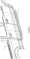
- FIG. 1is a perspective view of one embodiment of a vehicle step rail system in accordance with the present disclosure secured to the side of a motor vehicle, in this example a pickup truck;
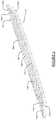
- FIG. 2is an enlarged perspective view of the step rail system of FIG. 1 wherein the step rail elements have curved leading and trailing ends;
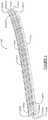
- FIG. 3is a perspective view of another step rail system in accordance with the present disclosure which makes use of step rail elements having a wave-like or undulating configuration over their full lengths;
- FIG. 4is a perspective view of another step rail system which shows the step rail elements thereof each having a straight configuration and being of identical construction;
- FIG. 5is a perspective view of another step rail system of the present disclosure in which each of the step rail elements are identical in construction, and wherein each has a curved leading and trailing end and the step rail elements are secured in a nested arrangement; and
- FIG. 6is a perspective view of another step rail system of the present disclosure in which the outermost step rail element includes angled portions that form a pair of planar step portions.
- FIG. 1one embodiment of a step rail system 10 is shown secured to a structural portion of a vehicle 12 .
- vehicle 12 in this exampleis shown as a pickup truck, but it will be appreciated that the vehicle could be any form of vehicle such as a van, an SUV, etc.
- the step rail system 10is not limited to use with only automotive vehicles, but may just as easily be used with ATVs and other types of vehicles. While FIG. 1 only illustrates one step rail system 10 being secured to one side of the vehicle 12 , it will be appreciated that an additional step rail system 10 will be typically be secured to the opposite side of the vehicle as well.
- the step rail system 10may include two, three, four or more independent rail elements 14 .
- the system 10makes use of three independent rail elements, that is an inner step rail element 14 a , an intermediate step rail element 14 b and an outermost step rail element 14 c .
- Step pad sections 16 a and 16 bmay be secured using external fastening elements (not shown), or possibly by suitable adhesives, or possibly even by an interference or friction fit between the rail elements 14 a - 14 c .
- a single, enlarged step padcould also be used in place of the two step pad sections 16 a and 16 b.
- Each rail element 14 a - 14 c in this exampleforms a generally square or slightly rectangular shaped element when viewed in cross section, but other shapes (i.e., round, oval, etc.) could be used as well.
- the rail elements 14 a and 14 bare formed as straight lengths of tubing, while the outermost rail element 14 c is formed with curved end portions 14 c 1 (i.e., curved leading and trailing end portions), which wrap around the opposing ends of the inner rail element 14 a and the intermediate step rail element 14 b .
- the opposite outermost ends 14 a 1 of the rail elements 14 a and the outermost ends 14 b 1 of the rail element 14 bare cut, machined or otherwise formed to accommodate the curvature of the inside surface of the outermost rail element 14 c .
- Thisenables the overall step rail system 10 to provide a highly aesthetically pleasing efficient appearance, as well as a highly aerodynamic configuration, without any significant gaps at the forward or rearward ends of the step rail system 10 .
- the use of three independent rail sections 14 a - 14 calso helps to enable draining of water from upper surfaces of the overall step rail system 10 , as well as helping to reduce the weight of the step rail system 10 .
- the step rail system 10may be secured to a structural portion of the vehicle 12 by any style of suitable support brackets (not shown) well known in the art.
- the rail sections 14 a - 14 cmay be formed from any suitable metallic or plastic materials, however, it is expected that aluminum will be an especially preferable material due to its strength, light weight and resistance to the elements.
- the step pad sections 16 a and 16 bare preferably made from a rubber or elastomer type material which provides excellent grip and traction when standing on the step rail system 10 , although other materials could be used as well, or a combination of metallic and non-metallic materials could be used.
- FIG. 3shows a step rail system 100 in accordance with another embodiment of the present disclosure.
- the step rail system 100 in this exampleincludes a rail element 102 a which is formed as a straight length of tubing, a rail element 102 b having a wavy or undulating shape along its length, and a third rail element 102 c shaped similar to the rail element 102 b and supported nestably adjacent to the rail element 102 b .
- Ends 102 b 1 of rail element 102are cut, machined or otherwise formed to enable the ends to merge toward rail element 102 a and enable the nesting positioning within rail elements 102 a and 102 c . While not shown in FIG.
- suitable end capsmay optionally be located at the ends of each of the rail elements 102 a - 102 c .
- Step pad sections 104 a and 104 bmay be attached in any suitable manner such as by threaded fasteners, adhesives or a friction fit to the rail elements 102 a - 102 c .
- the rail elements 102 a - 102 cmay be made from any suitable metallic or plastic materials, but it is expected that aluminum may be a preferred material.
- the step pad sections 104 a and 104 bmay be made from an elastomer or rubber material, or a combination of these materials and a metallic material as a substrate on which the elastomer or rubber is mounted.
- the overall “wavy” or “undulating” shape of the step rail system 100forms a highly aesthetic appearance, as well as a highly aerodynamic configuration, that complements the styling of a given vehicle on which the step rail system 100 is installed.
- the wavinessalso provides added surface width at those areas where an individual would typically step on when entering or exiting the vehicle 12 .
- FIG. 4shows a step rail system 200 in accordance with another embodiment of the present disclosure.
- the step rail system 200 in this exampleincludes three identically formed, straight step rail elements 202 a - 202 c that are secured closely adjacent one another.
- the step rail elements 202 a - 202 care formed with a square cross-sectional shape, although any cross sectional shape could be used (e.g., round, rectangular, oval, oblong, etc.).
- Step pad sections 204 a and 204 bmay be secured to the step rail elements 202 a - 202 c .
- End caps(not shown) may also be secured to the opposite ends of each step rail element 202 a - 202 c .
- the step rail elements 202 a - 202 cmay be made from any metallic or suitably strong plastic material, but again it is expected that aluminum will be a particularly preferred material.
- the step pad sections 204 a and 204 bmay be made from any suitable elastomer, rubber or even metallic material.
- FIG. 5shows a step rail system 300 in accordance with yet another embodiment of the present disclosure.
- Step rail system 300 in this exampleincludes three identical step rail elements 302 a - 302 c each having a slightly curved configuration, for example formed by a well-known stretch/bent forming process, along a majority of their lengths, with more pronounced curvatures at their leading edges and trailing edges 302 a 1 , 302 b 1 and 302 c 1 .
- one or more step padsmay be included with the system 300 as well.
- Ends 302 a 2 , 302 b 2 and 302 c 2are cut, machined or otherwise formed such that they form surfaces that are generally parallel to the side of the vehicle 12 body, and thus end portions of each is essentially hidden from view when the step rail system 300 is assembled onto the vehicle. Nevertheless, end caps (not shown) may also be assembled into the ends 302 a 2 , 302 b 2 and 302 c 2 to close off the ends. And while the step rail elements 302 a - 302 c are shown with a generally square cross-sectional configuration, it will be appreciated that virtually any cross-sectional shape (e.g., rectangular, round, oval, oblong, etc.) could be used for the step rail elements 302 a - 302 c.
- any cross-sectional shapee.g., rectangular, round, oval, oblong, etc.
- the step rail system 400 in this exampleincludes a straight inner rail element 402 , a straight intermediate rail element 404 and a complexly shaped outer rail element 406 .
- the rail elements 402 - 406 in this exampleare generally square shaped in cross section, although they need not be.
- the cross-sectional shapemay be rectangular, round, oval, circular, or virtually other cross sectional shape, and the step rail system 400 is not limited to the use of rail elements of any specific cross sectional shape.
- three step rail elements 402 - 406are shown, the system 400 could be modified to include greater or less than three such elements.
- the step rails elements 402 - 406may be formed through any suitable manufacturing technique, for exampling injection molding or extrusion molding, or by a stretch/bent molding technique.
- Aluminumis a particularly desirable material for forming the rail system 400 , although other materials such as stainless steel and even high strength plastics may potentially be used.
- the step rail elements 402 - 404may be secured at their opposing ends to inwardly facing wall portions of the complexly shaped outer rail element 406 through the use of threaded fastening elements, or otherwise brazed to the outer rail element 406 , or possible even secured by suitably strong adhesives, or a combination of such securing implements and engagement with cutout sections on the inner wall surface of the outer rail element 406 .
- the complexly shaped outer rail 406is unique in that it is formed to slope outwardly (in the horizontal plane) away from the inner rail 402 and the intermediate rail 404 , and also to provide curving front and rear sections 406 a and 406 b , respectively, as well as elevationally angled sections 406 d , planar step portions 406 e and a central portion 406 f .
- the elevationally angled sections 406 dhelp to provide a distinct “step” look to the outermost rail element 406 , as well as to define two distinct step areas where an individual may step to enter a vehicle.
- the elevationally angled step sections 406 dalso help to provide surfaces which may help prevent an individual's foot from slipping laterally (forwardly or rearwardly) along the outer rail 406 in the event the individual is leaning forwardly or rearwardly, relative to the length of the vehicle, while entering or exiting the vehicle.
- the curving front and rear sections 406 a and 406 b of the complexly shaped outer rail 406help to provide excellent aerodynamic qualities that minimize wind drag by the system 400 .
- rubber or elastomer elements pads or pad-like elementsmay be secured (either by conventional fasteners or adhesives) to upwardly facing surfaces of the planar step portions 406 e to provide an even further improved gripping surface when stepping onto the planar step portions.
- the step rail elements 14 a - 14 c , 100 a - 100 c ; 200 a - 200 c and 300 a - 300 c ; and 402 - 406may be fully exposed or partially exposed constant cross section dimension structural members. This significantly simplifies manufacturing because each of the step rail elements 14 a - 14 c , 100 a - 100 c , 200 a - 200 c , 300 a - 300 c , and 402 - 406 may be made using the same tooling, for example by extrusion or possibly even by a roll forming technique, or by a stretch/bent forming process.
- step rail elements 14 a - 14 c , 100 a - 100 c , 200 a - 200 c , 300 a - 300 c and 402 - 406are each positioned closely adjacent one another and in a nested fashion, such that each group of elements produces a suitable stepping surface or a suitable surface to attach a step pad to, which further increases the safety or aesthetics of the step rail system.
- Each of the step rail systems 100 , 200 , 300 and 400may be secured in the conventional fashion using a pair of spaced apart, suitable supports (typically L-shaped metallic elements), that may be coupled to the structural portion of the vehicle. Accordingly, the systems 100 - 400 do not require using complex mounting hardware to support them from the vehicle.
- step rail elementshaving different cross sectional dimensions could employed in each of the step rail systems 10 , 100 , 200 or 300 .
- Any or all of the step rail elementsmay also be bent or formed in two or three dimensions to improve the appearance or functionality of the assist step.
- the use of angled or curved cuts at the ends of one or multiple ones of the step rail elementsmay be utilized for the same purposes.
Landscapes
- Engineering & Computer Science (AREA)
- Mechanical Engineering (AREA)
- Body Structure For Vehicles (AREA)
Abstract
Description
Claims (17)
Priority Applications (1)
| Application Number | Priority Date | Filing Date | Title |
|---|---|---|---|
| US16/209,199US10723272B2 (en) | 2017-12-04 | 2018-12-04 | Step rail system for vehicle |
Applications Claiming Priority (2)
| Application Number | Priority Date | Filing Date | Title |
|---|---|---|---|
| US201762594218P | 2017-12-04 | 2017-12-04 | |
| US16/209,199US10723272B2 (en) | 2017-12-04 | 2018-12-04 | Step rail system for vehicle |
Publications (2)
| Publication Number | Publication Date |
|---|---|
| US20190168674A1 US20190168674A1 (en) | 2019-06-06 |
| US10723272B2true US10723272B2 (en) | 2020-07-28 |
Family
ID=66658796
Family Applications (1)
| Application Number | Title | Priority Date | Filing Date |
|---|---|---|---|
| US16/209,199Expired - Fee RelatedUS10723272B2 (en) | 2017-12-04 | 2018-12-04 | Step rail system for vehicle |
Country Status (1)
| Country | Link |
|---|---|
| US (1) | US10723272B2 (en) |
Citations (139)
| Publication number | Priority date | Publication date | Assignee | Title |
|---|---|---|---|---|
| US1310973A (en) | 1919-07-22 | Removable runming-board for automobiles | ||
| US1584573A (en)* | 1923-08-13 | 1926-05-11 | Winaloe U Stonehill | Running board or step for automobiles |
| US4004695A (en) | 1975-04-16 | 1977-01-25 | Fulton Industries, Inc. | Channel and plate telescopic crane boom |
| US4021055A (en) | 1976-04-08 | 1977-05-03 | Okland Merlyn C | Vehicle running board |
| US4057942A (en) | 1975-05-02 | 1977-11-15 | O & K Orenstein & Koppel Aktiengesellschaft | Telescopic boom with hydraulic actuating mechanism |
| US4094230A (en) | 1974-10-03 | 1978-06-13 | Walter Kidde & Company, Inc. | Self-aligning and end fixity connector for connecting a hydraulic cylinder piston rod to its respective section in a multi-section telescopic boom assembly |
| US4167272A (en) | 1978-07-26 | 1979-09-11 | Scranton Manufacturing | Mounting structure for a running board |
| US4240521A (en) | 1979-01-27 | 1980-12-23 | Kabushiki Kaisha Naka Gijutsu Kenkyusho | Drawer type emergency escape |
| US4253256A (en) | 1978-06-02 | 1981-03-03 | Feliz Jack M | Self-loading dualistic earth excavator with connecting telescopic conveying and dualistic distribution means |
| US4309854A (en) | 1978-09-18 | 1982-01-12 | Vendramini D | Telescopic mast |
| US4318488A (en) | 1980-07-28 | 1982-03-09 | Harnischfeger Corporation | Method of extending a jib of a telescopic crane |
| US4403421A (en) | 1980-11-13 | 1983-09-13 | Shepherd Daniel R | Telescopic gun sight |
| US4406375A (en) | 1980-07-02 | 1983-09-27 | Jlg Industries Inc. | Telescopic boom construction |
| US4424828A (en) | 1980-12-24 | 1984-01-10 | Zellinger Ing Hans | Vehicle for servicing aircraft |
| US4498263A (en) | 1981-09-23 | 1985-02-12 | Albert Bocker Gmbh & Co Kg | Telescopic beam |
| US4568808A (en) | 1983-04-29 | 1986-02-04 | Alsthom-Atlantique | Telescopic isolating switch |
| US4584776A (en) | 1980-11-13 | 1986-04-29 | Shepherd Daniel R | Telescopic gun sight |
| US4589076A (en) | 1983-10-17 | 1986-05-13 | Kabushiki Kaisha Kobe Seiko Sho | Method for controlling stretching and contracting operations of telescopic multistage boom |
| US4646794A (en) | 1985-08-08 | 1987-03-03 | Universal Hydraulics, Inc. | Telescopic rotary refueling system for battle tank |
| US4660731A (en) | 1981-10-05 | 1987-04-28 | Liebherr-Werk Ehingen Gmbh | Telescopic crane for heavy loads |
| US4674261A (en) | 1986-06-25 | 1987-06-23 | Sabel Herbert John | Machine for loading and closing a shipping case with a telescopic lid |
| US4699281A (en) | 1984-03-15 | 1987-10-13 | Kabushiki Kaisha Hikoma Seisakusho | Telescopic boom mechanism |
| US4733598A (en) | 1985-06-21 | 1988-03-29 | The 600 Group Plc | Telescopic jib |
| US4793437A (en) | 1987-07-20 | 1988-12-27 | Philip Hanthorn | Portable lift with telescopic booms and load-carrying apparatus |
| US4809472A (en) | 1987-09-25 | 1989-03-07 | Kidde Industries, Inc. | Carrier track assembly for extensible and retractable boom machines |
| US4932176A (en) | 1988-09-19 | 1990-06-12 | Gte Government Systems Corporation | Extendible and retractible mast system |
| US4944711A (en) | 1988-03-23 | 1990-07-31 | Kioritz Corporation | Extendable/retractable operational sleeve |
| US4944656A (en) | 1989-01-27 | 1990-07-31 | Feng Ou Yang | Telescopic rod means having rotatably retractable display sheet |
| US5110250A (en) | 1990-12-18 | 1992-05-05 | Kuo Zeal Sain | Double-story parking apparatus having telescopic access |
| US5135074A (en) | 1991-06-27 | 1992-08-04 | Simon Aerials Inc. | Telescopic boom elevating apparatus with a mechanical lift and level linkage system |
| US5148717A (en) | 1990-08-23 | 1992-09-22 | Nks Ltd. | Telescopic steering column apparatus |
| US5191828A (en) | 1992-06-18 | 1993-03-09 | Mccreery Robert B | Telescopic cylinder with increased lateral loading capacity |
| US5226853A (en) | 1990-11-23 | 1993-07-13 | Nacam | Telescopic coupling for steering systems |
| US5238287A (en) | 1992-08-14 | 1993-08-24 | Pioneer Consolidated Corporation | Front mount telescopic arm truck cover system |
| US5259664A (en) | 1992-04-14 | 1993-11-09 | David Cottle | Extendable/retractable foot/leg rest for a wheelchair |
| US5286049A (en) | 1991-10-09 | 1994-02-15 | Flex-N-Gate Corporation | Vehicle running board |
| US5423650A (en) | 1994-01-31 | 1995-06-13 | Zerbst; James E. | Retractable cargo rack assembly |
| US5489114A (en) | 1994-09-29 | 1996-02-06 | Kidde Industries, Inc. | Tie rod extendable and retractable telescopic axle assembly |
| US5513825A (en) | 1994-06-10 | 1996-05-07 | Ditto Sales | Telescopic adjustable height apparatus |
| JPH08175270A (en) | 1994-12-26 | 1996-07-09 | Kojima Press Co Ltd | Ladder for vehicle |
| US5584645A (en) | 1993-12-08 | 1996-12-17 | Ec Engineering & Consulting Spezialmachinen Gmbh | Telescopic boom with a multistage, lockable hydraulic cylinder protected against buckling |
| US5632395A (en) | 1994-02-25 | 1997-05-27 | Zimmermann; Horst | Telescopic rod |
| US5669562A (en) | 1996-02-28 | 1997-09-23 | Columbus Mckinnon Corporation | Telescoping infeed conveyor |
| US5718345A (en) | 1994-09-27 | 1998-02-17 | Kidde Industries, Inc. | Carrier track system for independent and/or synchronized operation of a multi-section telescopic boom structure |
| US5731987A (en) | 1993-12-23 | 1998-03-24 | Kidde Industries, Inc. | Telescopic booms |
| US5813552A (en) | 1993-12-08 | 1998-09-29 | Ec Engineering + Consulting Spezialmaschinen Gmbh | Telescopic boom with multistage hydraulic cylinder |
| US5877693A (en) | 1998-05-27 | 1999-03-02 | Grove U.S. L.L.C. | Method and apparatus for measuring the length of a multi-section telescopic boom |
| US5926961A (en) | 1996-05-04 | 1999-07-27 | Andreas Stihl Ag & Co. | Tree trimmer with telescopic rod |
| US5930934A (en) | 1993-03-28 | 1999-08-03 | Fisher; Timothy Dale | Variable power telescopic sight |
| US5938395A (en) | 1997-11-15 | 1999-08-17 | Dumont, Jr.; John W. | Retractable carrier-platform device |
| US6050579A (en) | 1998-04-21 | 2000-04-18 | Aeroquip Corporation | Automotive running board |
| US6062404A (en) | 1996-12-20 | 2000-05-16 | Grove U.S. L.L.C. | Device and method for arresting sections of a telescopic jib |
| US6176672B1 (en) | 1998-07-31 | 2001-01-23 | Gordon Egan | Telescoping personal motorcycle support structure |
| US6186347B1 (en) | 1998-07-07 | 2001-02-13 | Mannesmann Ag | Mobile crane with a telescopic jib |
| US6185875B1 (en) | 1996-08-20 | 2001-02-13 | Interkal, Inc. | Telescopic seating system with aisle hand rails |
| US6199325B1 (en) | 1999-03-02 | 2001-03-13 | Irwin Seating Company | Power system for extending and retracting a structure |
| US6199707B1 (en) | 1998-04-23 | 2001-03-13 | Kabushiki Kaisha Aichi Corporation | Telescopic boom |
| US6267398B1 (en) | 1998-09-25 | 2001-07-31 | Ockie Lombard | Multi-purpose motor vehicle accessory |
| US6280086B1 (en) | 1997-01-08 | 2001-08-28 | Thomas Regout B.V. | Telescopic rail with stop block |
| US20010018586A1 (en) | 1996-09-20 | 2001-08-30 | Ioan Cosmescu | Multifunctional telescopic monopolar/bipolar surgical device and method therefor |
| US6305820B1 (en) | 2000-02-13 | 2001-10-23 | Tupor Limited | Telescopic lantern |
| US20020056693A1 (en) | 2000-09-21 | 2002-05-16 | Atecs Mannesmann Ag | Locking unit for a telescopic jib of a crane and telescopic jib |
| US20030006576A1 (en)* | 2001-06-04 | 2003-01-09 | Ipl Inc | Molded running board |
| US6520523B2 (en) | 2001-05-02 | 2003-02-18 | Bradley L. Beck | Removable vehicle running boards |
| US6588783B2 (en) | 2001-11-07 | 2003-07-08 | Thomas Fichter | Apparatus for assisting entry into high road clearance vehicles |
| US20030127408A1 (en) | 2000-01-21 | 2003-07-10 | National Crane Corporation | Anti-two block wire internal to crane telescopic boom |
| US6592135B2 (en) | 2001-06-25 | 2003-07-15 | Theron V. Hendrix | Vehicle running board detachable for use as loading ramp |
| US6641358B2 (en) | 1999-10-04 | 2003-11-04 | C.G. Bretting Manufacturing Co., Inc. | Web stacker and separator apparatus and method |
| US6641355B1 (en) | 1998-04-17 | 2003-11-04 | Liftcon Technologies Limited | Transportable lift truck with telescopic lifting arm |
| US6830257B2 (en) | 2001-02-15 | 2004-12-14 | American Moto Products, Inc. | Retractable vehicle step |
| US20040256832A1 (en) | 2003-06-20 | 2004-12-23 | Ross Bradsen | Method of attaching an accessory such as a running board to a vehicle |
| US20050005562A1 (en) | 2000-12-05 | 2005-01-13 | Henderson Allan P. | Telescopic support tower |
| US20050053465A1 (en) | 2003-09-04 | 2005-03-10 | Atico International Usa, Inc. | Tower fan assembly with telescopic support column |
| US20050152749A1 (en) | 2002-06-19 | 2005-07-14 | Stephane Anres | Telescopic guide pipe for offshore drilling |
| US6938909B2 (en) | 2001-10-16 | 2005-09-06 | 89908, Inc. | Retractable vehicle step |
| US6942233B2 (en) | 2001-10-16 | 2005-09-13 | 89908, Inc. | Retractable vehicle step |
| US6942427B1 (en) | 2003-05-03 | 2005-09-13 | Nagan Srinivasan | Column-stabilized floating structure with telescopic keel tank for offshore applications and method of installation |
| US6955370B2 (en) | 2002-01-16 | 2005-10-18 | Ventra Group Inc. | Retractable running board |
| US20050269159A1 (en) | 2004-06-07 | 2005-12-08 | Lin Cho S | Telescopic stepladder |
| USD521439S1 (en) | 2003-03-03 | 2006-05-23 | Salflex Polymers Ltd. | Running board bracket |
| US7083179B2 (en) | 2003-03-03 | 2006-08-01 | Salflex Polymers Ltd. | Running board |
| US7118120B2 (en) | 2003-07-22 | 2006-10-10 | Magna International Inc. | Powered running board |
| US7168721B2 (en) | 2004-05-27 | 2007-01-30 | Steffens Enterprises, Inc. | Vehicle step tube |
| US7182175B1 (en) | 2004-08-16 | 2007-02-27 | G.G. Schmitt & Sons, Inc. | Retractable telescopic boat ladder |
| US7311320B2 (en) | 2005-10-17 | 2007-12-25 | Magna International Inc. | One piece running board bracket |
| US7318596B2 (en) | 2004-05-03 | 2008-01-15 | Ventra Group Inc. | Retractable running board |
| US7334807B2 (en) | 2004-05-27 | 2008-02-26 | Steffens Enterprises, Inc. | Vehicle step tube |
| US7412759B1 (en) | 2007-04-24 | 2008-08-19 | Hardinge Taiwan Precision Machine Ltd. | Telescopic safety shield for machine tool |
| US7488025B1 (en) | 2006-07-28 | 2009-02-10 | Roberson Andrew M | Truck bed extender and telescoping ramp |
| US20090044729A1 (en) | 2007-08-16 | 2009-02-19 | Shape Corporation | Multi-functional running board and ramp apparatus |
| US20090218444A1 (en) | 2005-10-27 | 2009-09-03 | Messier-Dowty Sa | undercarriage shock absorber with positive retention in a retracted position and with crash overtravel |
| US7600731B2 (en) | 2001-10-18 | 2009-10-13 | Res-Q-Jack, Inc. | Folding telescopic stabilization rescue strut with overextension prevention |
| US20090269179A1 (en) | 2008-03-12 | 2009-10-29 | Prosurgics Limited | Telescopic support |
| US7621546B2 (en) | 2006-10-31 | 2009-11-24 | Magna International Inc. | Illuminating bracket for use with a running board or step |
| US7635247B2 (en) | 2005-02-02 | 2009-12-22 | Collins Douglas A | Telescoping vehicle step |
| US7637518B2 (en) | 2006-04-20 | 2009-12-29 | Adair John T | Utility ramp and running board system |
| US7708294B2 (en) | 2006-11-02 | 2010-05-04 | Gm Global Technology Operations, Inc. | Detachable dual-use platform apparatus and method |
| US7717445B2 (en) | 2008-03-06 | 2010-05-18 | Nissan Technical Center North America, Inc. | Detachable side step assembly and method of use |
| US20100160814A1 (en) | 2008-12-18 | 2010-06-24 | Parihar Shailendra K | Biopsy Device with Telescoping Cutter Cover |
| US7788858B1 (en) | 2007-06-18 | 2010-09-07 | Ammons Douglas D | All terrain vehicle with telescoping camera |
| US7827641B2 (en) | 2006-03-15 | 2010-11-09 | Solvit Products, Lp | Telescoping ramp |
| US20100307870A1 (en) | 2009-06-05 | 2010-12-09 | Dirk Zimmerman | Telescopic ladder |
| US20110036084A1 (en) | 2008-02-21 | 2011-02-17 | Roeland Mallan | Vehicle cab tilting device with telescopic tilting cylinder |
| US7909344B1 (en) | 2008-04-08 | 2011-03-22 | Iron Cross Automotive, Inc | Adjustable vehicle step |
| US7909520B2 (en) | 2005-02-16 | 2011-03-22 | Jonathan Barabė | Telescopic viewing device |
| US8002298B2 (en) | 2007-07-04 | 2011-08-23 | Cnh America Llc | Vehicle having an elevated cab and access steps |
| US8016309B2 (en) | 2006-06-21 | 2011-09-13 | Salflex Polymers Ltd. | Running board for vehicle |
| US20110225903A1 (en) | 2010-03-22 | 2011-09-22 | Said Lounis | Telescopic mast system |
| US8136826B2 (en) | 2006-12-13 | 2012-03-20 | Magna International Inc. | Power retractable rocker board |
| US8156266B2 (en) | 2007-10-19 | 2012-04-10 | Sony Corporation | Consumer electronics control (CEC) line enhancement method for HDMI network that selects a transfer rate from a plurality of transfer rates |
| US8182470B2 (en) | 2005-12-20 | 2012-05-22 | Intuitive Surgical Operations, Inc. | Telescoping insertion axis of a robotic surgical system |
| US20120127300A1 (en) | 2010-11-23 | 2012-05-24 | National Applied Research Laboratories | Telescopic probe monitoring system for riverbedelevation monitoring at bridge piers |
| US20120152880A1 (en) | 2010-12-17 | 2012-06-21 | Manitowoc Crane Group France Sas | Telescoping system for crane jib and auxiliary jib |
| US20120193167A1 (en) | 2011-01-28 | 2012-08-02 | Appropriate Combined Technologies, Llc | Telescoping pull-down attic ladder |
| US8322580B1 (en) | 2010-07-12 | 2012-12-04 | Billy Hamilton | Retractable cargo carrying device |
| US8448968B1 (en) | 2012-03-19 | 2013-05-28 | Luverne Truck Equipment, Inc. | Adaptable vehicle step assembly |
| US20130284010A1 (en) | 2012-04-26 | 2013-10-31 | Labrie Environmental Group Inc. | Telescopic cylinder |
| US20130305627A1 (en) | 2012-05-15 | 2013-11-21 | Richard S. Pike | Telescopic support for an expandable shelter |
| US8590951B1 (en) | 2011-08-05 | 2013-11-26 | Michael Calabro | Retractable impact protection system for use with a vehicle body |
| US20140059949A1 (en) | 2012-09-06 | 2014-03-06 | Said Lounis | Telescopic multi-mast system |
| US8707495B2 (en) | 2011-10-13 | 2014-04-29 | Cequent Consumer Products | Self adjusting ramp |
| US8714575B2 (en) | 2008-02-19 | 2014-05-06 | Magna International Inc | Automated retractable running board |
| US8777074B2 (en) | 2010-10-22 | 2014-07-15 | Michael Thomas DeMers | Hitch-mounted telescopic rack and method of use |
| US20140264213A1 (en) | 2013-03-12 | 2014-09-18 | Jerry Lynn NIPPER | Telescoping Boom Hoist System |
| US20150008207A1 (en) | 2013-07-04 | 2015-01-08 | Liebherr-Werk Ehingen Gmbh | Collar bearing for a telescopic boom as well as telescopic boom and crane |
| US20150091270A1 (en)* | 2013-09-27 | 2015-04-02 | Lund, Inc. | Modular rail and step system |
| US20150113884A1 (en) | 2013-10-24 | 2015-04-30 | Rodney J. Klingenberg | Telescopic or retractable bleacher handrail and system |
| US20150135454A1 (en) | 2013-11-15 | 2015-05-21 | S.C. Johnson & Son, Inc. | Extendable tool attachment stick |
| US20150144583A1 (en) | 2013-11-26 | 2015-05-28 | Tadano Ltd. | Boom extending and retracting apparatus of a crane |
| US20150211250A1 (en) | 2012-09-06 | 2015-07-30 | Falck Schmidt Defence Systems A/S | Telescopic mast |
| US9198488B2 (en) | 2011-08-05 | 2015-12-01 | Gipron Giuseppe Pronzati S.R.L. | Telescopic stick foldable in two portions |
| US9221401B1 (en) | 2014-01-31 | 2015-12-29 | Brian Birkenstock | Telescopic bracket assembly for vehicle waste tanks |
| US9333919B2 (en) | 2014-08-26 | 2016-05-10 | Robert Crandall | Extruded support members for facilitating access to a vehicle and related methods |
| US20160185273A1 (en) | 2013-12-20 | 2016-06-30 | Jac Products, Inc. | Combination step rail assembly for use as a step platform or a ramp on a vehicle |
| US9539948B1 (en) | 2016-03-22 | 2017-01-10 | Jac Products, Inc. | Telescoping step assist system and method |
| US20170036596A1 (en)* | 2015-08-06 | 2017-02-09 | Tayih Lun An Co., Ltd. | Vehicle running board |
| US20180043832A1 (en)* | 2016-08-12 | 2018-02-15 | Mitsui Kinzoku Act Corporation | Control device of electric step for vehicle |
| US9963060B1 (en)* | 2017-10-23 | 2018-05-08 | David A. Vick | Vehicle running board assembly for use as a ramp |
| US20190054860A1 (en)* | 2017-08-16 | 2019-02-21 | Winbo-Dongjian Automotive Technology Co.,Ltd. | Vehicle side bar and vehicle with the same |
- 2018
- 2018-12-04USUS16/209,199patent/US10723272B2/ennot_activeExpired - Fee Related
Patent Citations (160)
| Publication number | Priority date | Publication date | Assignee | Title |
|---|---|---|---|---|
| US1310973A (en) | 1919-07-22 | Removable runming-board for automobiles | ||
| US1584573A (en)* | 1923-08-13 | 1926-05-11 | Winaloe U Stonehill | Running board or step for automobiles |
| US4094230A (en) | 1974-10-03 | 1978-06-13 | Walter Kidde & Company, Inc. | Self-aligning and end fixity connector for connecting a hydraulic cylinder piston rod to its respective section in a multi-section telescopic boom assembly |
| US4004695A (en) | 1975-04-16 | 1977-01-25 | Fulton Industries, Inc. | Channel and plate telescopic crane boom |
| US4057942A (en) | 1975-05-02 | 1977-11-15 | O & K Orenstein & Koppel Aktiengesellschaft | Telescopic boom with hydraulic actuating mechanism |
| US4021055A (en) | 1976-04-08 | 1977-05-03 | Okland Merlyn C | Vehicle running board |
| US4253256A (en) | 1978-06-02 | 1981-03-03 | Feliz Jack M | Self-loading dualistic earth excavator with connecting telescopic conveying and dualistic distribution means |
| US4167272A (en) | 1978-07-26 | 1979-09-11 | Scranton Manufacturing | Mounting structure for a running board |
| US4309854A (en) | 1978-09-18 | 1982-01-12 | Vendramini D | Telescopic mast |
| US4240521A (en) | 1979-01-27 | 1980-12-23 | Kabushiki Kaisha Naka Gijutsu Kenkyusho | Drawer type emergency escape |
| US4406375A (en) | 1980-07-02 | 1983-09-27 | Jlg Industries Inc. | Telescopic boom construction |
| US4318488A (en) | 1980-07-28 | 1982-03-09 | Harnischfeger Corporation | Method of extending a jib of a telescopic crane |
| US4403421A (en) | 1980-11-13 | 1983-09-13 | Shepherd Daniel R | Telescopic gun sight |
| US4584776A (en) | 1980-11-13 | 1986-04-29 | Shepherd Daniel R | Telescopic gun sight |
| US4424828A (en) | 1980-12-24 | 1984-01-10 | Zellinger Ing Hans | Vehicle for servicing aircraft |
| US4498263A (en) | 1981-09-23 | 1985-02-12 | Albert Bocker Gmbh & Co Kg | Telescopic beam |
| US4660731A (en) | 1981-10-05 | 1987-04-28 | Liebherr-Werk Ehingen Gmbh | Telescopic crane for heavy loads |
| US4568808A (en) | 1983-04-29 | 1986-02-04 | Alsthom-Atlantique | Telescopic isolating switch |
| US4589076A (en) | 1983-10-17 | 1986-05-13 | Kabushiki Kaisha Kobe Seiko Sho | Method for controlling stretching and contracting operations of telescopic multistage boom |
| US4699281A (en) | 1984-03-15 | 1987-10-13 | Kabushiki Kaisha Hikoma Seisakusho | Telescopic boom mechanism |
| US4733598A (en) | 1985-06-21 | 1988-03-29 | The 600 Group Plc | Telescopic jib |
| US4646794A (en) | 1985-08-08 | 1987-03-03 | Universal Hydraulics, Inc. | Telescopic rotary refueling system for battle tank |
| US4674261A (en) | 1986-06-25 | 1987-06-23 | Sabel Herbert John | Machine for loading and closing a shipping case with a telescopic lid |
| US4793437A (en) | 1987-07-20 | 1988-12-27 | Philip Hanthorn | Portable lift with telescopic booms and load-carrying apparatus |
| US4809472A (en) | 1987-09-25 | 1989-03-07 | Kidde Industries, Inc. | Carrier track assembly for extensible and retractable boom machines |
| US4944711A (en) | 1988-03-23 | 1990-07-31 | Kioritz Corporation | Extendable/retractable operational sleeve |
| US4932176A (en) | 1988-09-19 | 1990-06-12 | Gte Government Systems Corporation | Extendible and retractible mast system |
| US4944656A (en) | 1989-01-27 | 1990-07-31 | Feng Ou Yang | Telescopic rod means having rotatably retractable display sheet |
| US5148717A (en) | 1990-08-23 | 1992-09-22 | Nks Ltd. | Telescopic steering column apparatus |
| US5226853A (en) | 1990-11-23 | 1993-07-13 | Nacam | Telescopic coupling for steering systems |
| US5110250A (en) | 1990-12-18 | 1992-05-05 | Kuo Zeal Sain | Double-story parking apparatus having telescopic access |
| US5135074A (en) | 1991-06-27 | 1992-08-04 | Simon Aerials Inc. | Telescopic boom elevating apparatus with a mechanical lift and level linkage system |
| US5286049A (en) | 1991-10-09 | 1994-02-15 | Flex-N-Gate Corporation | Vehicle running board |
| US5259664A (en) | 1992-04-14 | 1993-11-09 | David Cottle | Extendable/retractable foot/leg rest for a wheelchair |
| US5191828A (en) | 1992-06-18 | 1993-03-09 | Mccreery Robert B | Telescopic cylinder with increased lateral loading capacity |
| US5238287A (en) | 1992-08-14 | 1993-08-24 | Pioneer Consolidated Corporation | Front mount telescopic arm truck cover system |
| US5930934A (en) | 1993-03-28 | 1999-08-03 | Fisher; Timothy Dale | Variable power telescopic sight |
| US5584645A (en) | 1993-12-08 | 1996-12-17 | Ec Engineering & Consulting Spezialmachinen Gmbh | Telescopic boom with a multistage, lockable hydraulic cylinder protected against buckling |
| US5813552A (en) | 1993-12-08 | 1998-09-29 | Ec Engineering + Consulting Spezialmaschinen Gmbh | Telescopic boom with multistage hydraulic cylinder |
| US5731987A (en) | 1993-12-23 | 1998-03-24 | Kidde Industries, Inc. | Telescopic booms |
| US5423650A (en) | 1994-01-31 | 1995-06-13 | Zerbst; James E. | Retractable cargo rack assembly |
| US5632395A (en) | 1994-02-25 | 1997-05-27 | Zimmermann; Horst | Telescopic rod |
| US5513825A (en) | 1994-06-10 | 1996-05-07 | Ditto Sales | Telescopic adjustable height apparatus |
| US5718345A (en) | 1994-09-27 | 1998-02-17 | Kidde Industries, Inc. | Carrier track system for independent and/or synchronized operation of a multi-section telescopic boom structure |
| US5489114A (en) | 1994-09-29 | 1996-02-06 | Kidde Industries, Inc. | Tie rod extendable and retractable telescopic axle assembly |
| JPH08175270A (en) | 1994-12-26 | 1996-07-09 | Kojima Press Co Ltd | Ladder for vehicle |
| US5669562A (en) | 1996-02-28 | 1997-09-23 | Columbus Mckinnon Corporation | Telescoping infeed conveyor |
| US5926961A (en) | 1996-05-04 | 1999-07-27 | Andreas Stihl Ag & Co. | Tree trimmer with telescopic rod |
| US6185875B1 (en) | 1996-08-20 | 2001-02-13 | Interkal, Inc. | Telescopic seating system with aisle hand rails |
| US20010018586A1 (en) | 1996-09-20 | 2001-08-30 | Ioan Cosmescu | Multifunctional telescopic monopolar/bipolar surgical device and method therefor |
| US6062404A (en) | 1996-12-20 | 2000-05-16 | Grove U.S. L.L.C. | Device and method for arresting sections of a telescopic jib |
| US6280086B1 (en) | 1997-01-08 | 2001-08-28 | Thomas Regout B.V. | Telescopic rail with stop block |
| US5938395A (en) | 1997-11-15 | 1999-08-17 | Dumont, Jr.; John W. | Retractable carrier-platform device |
| US6641355B1 (en) | 1998-04-17 | 2003-11-04 | Liftcon Technologies Limited | Transportable lift truck with telescopic lifting arm |
| US6050579A (en) | 1998-04-21 | 2000-04-18 | Aeroquip Corporation | Automotive running board |
| US6199707B1 (en) | 1998-04-23 | 2001-03-13 | Kabushiki Kaisha Aichi Corporation | Telescopic boom |
| US5877693A (en) | 1998-05-27 | 1999-03-02 | Grove U.S. L.L.C. | Method and apparatus for measuring the length of a multi-section telescopic boom |
| US6186347B1 (en) | 1998-07-07 | 2001-02-13 | Mannesmann Ag | Mobile crane with a telescopic jib |
| US6176672B1 (en) | 1998-07-31 | 2001-01-23 | Gordon Egan | Telescoping personal motorcycle support structure |
| US6267398B1 (en) | 1998-09-25 | 2001-07-31 | Ockie Lombard | Multi-purpose motor vehicle accessory |
| US6199325B1 (en) | 1999-03-02 | 2001-03-13 | Irwin Seating Company | Power system for extending and retracting a structure |
| US6641358B2 (en) | 1999-10-04 | 2003-11-04 | C.G. Bretting Manufacturing Co., Inc. | Web stacker and separator apparatus and method |
| US20030127408A1 (en) | 2000-01-21 | 2003-07-10 | National Crane Corporation | Anti-two block wire internal to crane telescopic boom |
| US6305820B1 (en) | 2000-02-13 | 2001-10-23 | Tupor Limited | Telescopic lantern |
| US6575318B2 (en) | 2000-09-21 | 2003-06-10 | Atecs Mannesmann Ag | Locking unit for a telescopic jib of a crane and telescopic jib |
| US20020056693A1 (en) | 2000-09-21 | 2002-05-16 | Atecs Mannesmann Ag | Locking unit for a telescopic jib of a crane and telescopic jib |
| US20050005562A1 (en) | 2000-12-05 | 2005-01-13 | Henderson Allan P. | Telescopic support tower |
| US20090211174A1 (en) | 2000-12-05 | 2009-08-27 | Henderson Allan P | Telescopic support tower |
| US6830257B2 (en) | 2001-02-15 | 2004-12-14 | American Moto Products, Inc. | Retractable vehicle step |
| US7380807B2 (en) | 2001-02-15 | 2008-06-03 | 89908, Inc. | Retractable vehicle step |
| US7055839B2 (en) | 2001-02-15 | 2006-06-06 | 89908, Inc. | Retractable vehicle step |
| US8844957B2 (en) | 2001-02-15 | 2014-09-30 | Lund Motion Products, Inc. | Retractable vehicle step |
| US7413204B2 (en) | 2001-02-15 | 2008-08-19 | 89908, Inc. | Retractable vehicle step |
| US6520523B2 (en) | 2001-05-02 | 2003-02-18 | Bradley L. Beck | Removable vehicle running boards |
| US20030006576A1 (en)* | 2001-06-04 | 2003-01-09 | Ipl Inc | Molded running board |
| US6592135B2 (en) | 2001-06-25 | 2003-07-15 | Theron V. Hendrix | Vehicle running board detachable for use as loading ramp |
| US7007961B2 (en) | 2001-10-16 | 2006-03-07 | 89908, Inc. | Retractable vehicle step |
| US6942233B2 (en) | 2001-10-16 | 2005-09-13 | 89908, Inc. | Retractable vehicle step |
| US7566064B2 (en) | 2001-10-16 | 2009-07-28 | 88908, Inc. | Retractable vehicle step |
| US6938909B2 (en) | 2001-10-16 | 2005-09-06 | 89908, Inc. | Retractable vehicle step |
| US7398985B2 (en) | 2001-10-16 | 2008-07-15 | 89908, Inc. | Retractable vehicle step |
| US7600731B2 (en) | 2001-10-18 | 2009-10-13 | Res-Q-Jack, Inc. | Folding telescopic stabilization rescue strut with overextension prevention |
| US7416202B2 (en) | 2001-11-07 | 2008-08-26 | Thomas Fichter | Apparatus for assisting entry into high road clearance vehicles |
| US6874801B2 (en) | 2001-11-07 | 2005-04-05 | Thomas Fichter | Apparatus for assisting entry into high road clearance vehicles |
| US6588783B2 (en) | 2001-11-07 | 2003-07-08 | Thomas Fichter | Apparatus for assisting entry into high road clearance vehicles |
| US6955370B2 (en) | 2002-01-16 | 2005-10-18 | Ventra Group Inc. | Retractable running board |
| US7377531B2 (en) | 2002-01-16 | 2008-05-27 | Ventra Group Inc. | Retractable running board |
| US20050152749A1 (en) | 2002-06-19 | 2005-07-14 | Stephane Anres | Telescopic guide pipe for offshore drilling |
| US7083179B2 (en) | 2003-03-03 | 2006-08-01 | Salflex Polymers Ltd. | Running board |
| USD521439S1 (en) | 2003-03-03 | 2006-05-23 | Salflex Polymers Ltd. | Running board bracket |
| US6942427B1 (en) | 2003-05-03 | 2005-09-13 | Nagan Srinivasan | Column-stabilized floating structure with telescopic keel tank for offshore applications and method of installation |
| US20040256832A1 (en) | 2003-06-20 | 2004-12-23 | Ross Bradsen | Method of attaching an accessory such as a running board to a vehicle |
| US7118120B2 (en) | 2003-07-22 | 2006-10-10 | Magna International Inc. | Powered running board |
| US20050053465A1 (en) | 2003-09-04 | 2005-03-10 | Atico International Usa, Inc. | Tower fan assembly with telescopic support column |
| US7318596B2 (en) | 2004-05-03 | 2008-01-15 | Ventra Group Inc. | Retractable running board |
| US7168721B2 (en) | 2004-05-27 | 2007-01-30 | Steffens Enterprises, Inc. | Vehicle step tube |
| US7334807B2 (en) | 2004-05-27 | 2008-02-26 | Steffens Enterprises, Inc. | Vehicle step tube |
| US20050269159A1 (en) | 2004-06-07 | 2005-12-08 | Lin Cho S | Telescopic stepladder |
| US7182175B1 (en) | 2004-08-16 | 2007-02-27 | G.G. Schmitt & Sons, Inc. | Retractable telescopic boat ladder |
| US7635247B2 (en) | 2005-02-02 | 2009-12-22 | Collins Douglas A | Telescoping vehicle step |
| US7909520B2 (en) | 2005-02-16 | 2011-03-22 | Jonathan Barabė | Telescopic viewing device |
| US7311320B2 (en) | 2005-10-17 | 2007-12-25 | Magna International Inc. | One piece running board bracket |
| US20090218444A1 (en) | 2005-10-27 | 2009-09-03 | Messier-Dowty Sa | undercarriage shock absorber with positive retention in a retracted position and with crash overtravel |
| US20140163581A1 (en) | 2005-12-20 | 2014-06-12 | Intuitive Surgical Operations, Inc. | Telescoping Insertion Axis of a Robotic Surgical System |
| US20120209292A1 (en) | 2005-12-20 | 2012-08-16 | Intuitive Surgical Operations, Inc. | Telescoping Insertion Axis of a Robotic Surgical System |
| US8182470B2 (en) | 2005-12-20 | 2012-05-22 | Intuitive Surgical Operations, Inc. | Telescoping insertion axis of a robotic surgical system |
| US8641700B2 (en) | 2005-12-20 | 2014-02-04 | Intuitive Surgical Operations, Inc. | Telescoping insertion axis of a robotic surgical system |
| US7827641B2 (en) | 2006-03-15 | 2010-11-09 | Solvit Products, Lp | Telescoping ramp |
| US7637518B2 (en) | 2006-04-20 | 2009-12-29 | Adair John T | Utility ramp and running board system |
| US8016309B2 (en) | 2006-06-21 | 2011-09-13 | Salflex Polymers Ltd. | Running board for vehicle |
| US7488025B1 (en) | 2006-07-28 | 2009-02-10 | Roberson Andrew M | Truck bed extender and telescoping ramp |
| US7621546B2 (en) | 2006-10-31 | 2009-11-24 | Magna International Inc. | Illuminating bracket for use with a running board or step |
| US7708294B2 (en) | 2006-11-02 | 2010-05-04 | Gm Global Technology Operations, Inc. | Detachable dual-use platform apparatus and method |
| US8136826B2 (en) | 2006-12-13 | 2012-03-20 | Magna International Inc. | Power retractable rocker board |
| US7412759B1 (en) | 2007-04-24 | 2008-08-19 | Hardinge Taiwan Precision Machine Ltd. | Telescopic safety shield for machine tool |
| US7788858B1 (en) | 2007-06-18 | 2010-09-07 | Ammons Douglas D | All terrain vehicle with telescoping camera |
| US8002298B2 (en) | 2007-07-04 | 2011-08-23 | Cnh America Llc | Vehicle having an elevated cab and access steps |
| US20090044729A1 (en) | 2007-08-16 | 2009-02-19 | Shape Corporation | Multi-functional running board and ramp apparatus |
| US8156266B2 (en) | 2007-10-19 | 2012-04-10 | Sony Corporation | Consumer electronics control (CEC) line enhancement method for HDMI network that selects a transfer rate from a plurality of transfer rates |
| US8714575B2 (en) | 2008-02-19 | 2014-05-06 | Magna International Inc | Automated retractable running board |
| US20110036084A1 (en) | 2008-02-21 | 2011-02-17 | Roeland Mallan | Vehicle cab tilting device with telescopic tilting cylinder |
| US7717445B2 (en) | 2008-03-06 | 2010-05-18 | Nissan Technical Center North America, Inc. | Detachable side step assembly and method of use |
| US20090269179A1 (en) | 2008-03-12 | 2009-10-29 | Prosurgics Limited | Telescopic support |
| US7909344B1 (en) | 2008-04-08 | 2011-03-22 | Iron Cross Automotive, Inc | Adjustable vehicle step |
| US20100160814A1 (en) | 2008-12-18 | 2010-06-24 | Parihar Shailendra K | Biopsy Device with Telescoping Cutter Cover |
| US20100307870A1 (en) | 2009-06-05 | 2010-12-09 | Dirk Zimmerman | Telescopic ladder |
| US20110225903A1 (en) | 2010-03-22 | 2011-09-22 | Said Lounis | Telescopic mast system |
| US8276326B2 (en) | 2010-03-22 | 2012-10-02 | Serapid Inc. | Telescopic mast system |
| US8322580B1 (en) | 2010-07-12 | 2012-12-04 | Billy Hamilton | Retractable cargo carrying device |
| US8777074B2 (en) | 2010-10-22 | 2014-07-15 | Michael Thomas DeMers | Hitch-mounted telescopic rack and method of use |
| US20120127300A1 (en) | 2010-11-23 | 2012-05-24 | National Applied Research Laboratories | Telescopic probe monitoring system for riverbedelevation monitoring at bridge piers |
| US8558881B2 (en) | 2010-11-23 | 2013-10-15 | National Applied Research Labortories | Telescopic probe monitoring system for riverbedelevation monitoring at bridge piers |
| US20120152880A1 (en) | 2010-12-17 | 2012-06-21 | Manitowoc Crane Group France Sas | Telescoping system for crane jib and auxiliary jib |
| US8893905B2 (en) | 2010-12-17 | 2014-11-25 | Manitowoc Crane Group France Sas | Telescoping system for crane jib and auxiliary jib |
| US20120193167A1 (en) | 2011-01-28 | 2012-08-02 | Appropriate Combined Technologies, Llc | Telescoping pull-down attic ladder |
| US8695760B2 (en) | 2011-01-28 | 2014-04-15 | Appropriate Combined Technologies, Llc | Telescoping pull-down attic ladder |
| US8590951B1 (en) | 2011-08-05 | 2013-11-26 | Michael Calabro | Retractable impact protection system for use with a vehicle body |
| US9198488B2 (en) | 2011-08-05 | 2015-12-01 | Gipron Giuseppe Pronzati S.R.L. | Telescopic stick foldable in two portions |
| US8707495B2 (en) | 2011-10-13 | 2014-04-29 | Cequent Consumer Products | Self adjusting ramp |
| US8448968B1 (en) | 2012-03-19 | 2013-05-28 | Luverne Truck Equipment, Inc. | Adaptable vehicle step assembly |
| US20130284010A1 (en) | 2012-04-26 | 2013-10-31 | Labrie Environmental Group Inc. | Telescopic cylinder |
| US20130305627A1 (en) | 2012-05-15 | 2013-11-21 | Richard S. Pike | Telescopic support for an expandable shelter |
| US20150211250A1 (en) | 2012-09-06 | 2015-07-30 | Falck Schmidt Defence Systems A/S | Telescopic mast |
| US20140059949A1 (en) | 2012-09-06 | 2014-03-06 | Said Lounis | Telescopic multi-mast system |
| US20140264213A1 (en) | 2013-03-12 | 2014-09-18 | Jerry Lynn NIPPER | Telescoping Boom Hoist System |
| US9161526B2 (en) | 2013-03-12 | 2015-10-20 | Jerry Lynn NIPPER | Telescoping boom hoist system |
| US20150008207A1 (en) | 2013-07-04 | 2015-01-08 | Liebherr-Werk Ehingen Gmbh | Collar bearing for a telescopic boom as well as telescopic boom and crane |
| US20150091270A1 (en)* | 2013-09-27 | 2015-04-02 | Lund, Inc. | Modular rail and step system |
| US20150113884A1 (en) | 2013-10-24 | 2015-04-30 | Rodney J. Klingenberg | Telescopic or retractable bleacher handrail and system |
| US20150135454A1 (en) | 2013-11-15 | 2015-05-21 | S.C. Johnson & Son, Inc. | Extendable tool attachment stick |
| US20150144583A1 (en) | 2013-11-26 | 2015-05-28 | Tadano Ltd. | Boom extending and retracting apparatus of a crane |
| US20160185273A1 (en) | 2013-12-20 | 2016-06-30 | Jac Products, Inc. | Combination step rail assembly for use as a step platform or a ramp on a vehicle |
| US9855877B2 (en) | 2013-12-20 | 2018-01-02 | Jac Products, Inc. | Combination step rail assembly for use as a step platform or a ramp on a vehicle |
| US9221401B1 (en) | 2014-01-31 | 2015-12-29 | Brian Birkenstock | Telescopic bracket assembly for vehicle waste tanks |
| US9333919B2 (en) | 2014-08-26 | 2016-05-10 | Robert Crandall | Extruded support members for facilitating access to a vehicle and related methods |
| US20170036596A1 (en)* | 2015-08-06 | 2017-02-09 | Tayih Lun An Co., Ltd. | Vehicle running board |
| US9539948B1 (en) | 2016-03-22 | 2017-01-10 | Jac Products, Inc. | Telescoping step assist system and method |
| US20180043832A1 (en)* | 2016-08-12 | 2018-02-15 | Mitsui Kinzoku Act Corporation | Control device of electric step for vehicle |
| US20190054860A1 (en)* | 2017-08-16 | 2019-02-21 | Winbo-Dongjian Automotive Technology Co.,Ltd. | Vehicle side bar and vehicle with the same |
| US9963060B1 (en)* | 2017-10-23 | 2018-05-08 | David A. Vick | Vehicle running board assembly for use as a ramp |
Also Published As
| Publication number | Publication date |
|---|---|
| US20190168674A1 (en) | 2019-06-06 |
Similar Documents
| Publication | Publication Date | Title |
|---|---|---|
| EP2172368B1 (en) | System and method for vehicle article carrier having stowable cross bars | |
| US8827293B1 (en) | Decorative side bar for a motor vehicle | |
| US7543872B1 (en) | Slidable cargo bay system | |
| US7552955B2 (en) | Hybrid bumper with trim | |
| US20190176717A1 (en) | Vehicle article carrier system incorporating electronic components | |
| US8627989B2 (en) | Support rail for a vehicle article carrier having blow molded decorative rail structure | |
| US20030116937A1 (en) | Telescoping bicycle fender | |
| US20060237501A1 (en) | Roof carrier for fishing rods | |
| US11713087B2 (en) | Vehicle accessory | |
| US10604076B2 (en) | Running board for vehicles | |
| US20020079667A1 (en) | Vehicle side step assembly | |
| CA2391041A1 (en) | Vehicle article carrier having telescopically extendable article carrier portion | |
| CN101171157A (en) | Hybrid bumper with trim | |
| CN219339616U (en) | Central rearview mirror | |
| US10723272B2 (en) | Step rail system for vehicle | |
| US9944230B2 (en) | Composite running board | |
| US11014617B2 (en) | Vehicle bed side wall configured for vertical load support | |
| CN104943546A (en) | Instrument panel | |
| EP4177112B1 (en) | Vehicle article carrier rack system with stowable, concealable cross bars | |
| CN110758254B (en) | Side edge protection device | |
| US20050087950A1 (en) | Vehicle step | |
| CN214929344U (en) | A car pedal and car | |
| US20160362056A1 (en) | Roof rack crossbar assembly | |
| CN209955922U (en) | Automobile protective bar and automobile | |
| CN209700526U (en) | car side sills and cars |
Legal Events
| Date | Code | Title | Description |
|---|---|---|---|
| FEPP | Fee payment procedure | Free format text:ENTITY STATUS SET TO UNDISCOUNTED (ORIGINAL EVENT CODE: BIG.); ENTITY STATUS OF PATENT OWNER: LARGE ENTITY | |
| STPP | Information on status: patent application and granting procedure in general | Free format text:DOCKETED NEW CASE - READY FOR EXAMINATION | |
| AS | Assignment | Owner name:JAC PRODUCTS, INC., MICHIGAN Free format text:ASSIGNMENT OF ASSIGNORS INTEREST;ASSIGNORS:GOMES, GERALD J.;PRESLEY, MICHAEL J.;HATHAWAY, BRENDAN J.;AND OTHERS;REEL/FRAME:048221/0496 Effective date:20190111 | |
| STPP | Information on status: patent application and granting procedure in general | Free format text:NON FINAL ACTION MAILED | |
| AS | Assignment | Owner name:JPMORGAN CHASE BANK N.A., ILLINOIS Free format text:SECURITY INTEREST;ASSIGNORS:JAC HOLDING CORPORATION;JAC PRODUCTS, INC.;JAC FINANCE CORP.;AND OTHERS;REEL/FRAME:050243/0879 Effective date:20190829 | |
| STPP | Information on status: patent application and granting procedure in general | Free format text:NON FINAL ACTION MAILED | |
| STPP | Information on status: patent application and granting procedure in general | Free format text:RESPONSE TO NON-FINAL OFFICE ACTION ENTERED AND FORWARDED TO EXAMINER | |
| STPP | Information on status: patent application and granting procedure in general | Free format text:NOTICE OF ALLOWANCE MAILED -- APPLICATION RECEIVED IN OFFICE OF PUBLICATIONS | |
| STPP | Information on status: patent application and granting procedure in general | Free format text:PUBLICATIONS -- ISSUE FEE PAYMENT VERIFIED | |
| STCF | Information on status: patent grant | Free format text:PATENTED CASE | |
| FEPP | Fee payment procedure | Free format text:MAINTENANCE FEE REMINDER MAILED (ORIGINAL EVENT CODE: REM.); ENTITY STATUS OF PATENT OWNER: LARGE ENTITY | |
| LAPS | Lapse for failure to pay maintenance fees | Free format text:PATENT EXPIRED FOR FAILURE TO PAY MAINTENANCE FEES (ORIGINAL EVENT CODE: EXP.); ENTITY STATUS OF PATENT OWNER: LARGE ENTITY | |
| STCH | Information on status: patent discontinuation | Free format text:PATENT EXPIRED DUE TO NONPAYMENT OF MAINTENANCE FEES UNDER 37 CFR 1.362 | |
| FP | Lapsed due to failure to pay maintenance fee | Effective date:20240728 |