US10723211B2 - Integrated powertrain system - Google Patents
Integrated powertrain systemDownload PDFInfo
- Publication number
- US10723211B2 US10723211B2US15/675,587US201715675587AUS10723211B2US 10723211 B2US10723211 B2US 10723211B2US 201715675587 AUS201715675587 AUS 201715675587AUS 10723211 B2US10723211 B2US 10723211B2
- Authority
- US
- United States
- Prior art keywords
- housing
- electric motor
- gear reducer
- wheel
- electric vehicle
- Prior art date
- Legal status (The legal status is an assumption and is not a legal conclusion. Google has not performed a legal analysis and makes no representation as to the accuracy of the status listed.)
- Active
Links
Images


Classifications
- B—PERFORMING OPERATIONS; TRANSPORTING
- B60—VEHICLES IN GENERAL
- B60K—ARRANGEMENT OR MOUNTING OF PROPULSION UNITS OR OF TRANSMISSIONS IN VEHICLES; ARRANGEMENT OR MOUNTING OF PLURAL DIVERSE PRIME-MOVERS IN VEHICLES; AUXILIARY DRIVES FOR VEHICLES; INSTRUMENTATION OR DASHBOARDS FOR VEHICLES; ARRANGEMENTS IN CONNECTION WITH COOLING, AIR INTAKE, GAS EXHAUST OR FUEL SUPPLY OF PROPULSION UNITS IN VEHICLES
- B60K1/00—Arrangement or mounting of electrical propulsion units
- B60K1/04—Arrangement or mounting of electrical propulsion units of the electric storage means for propulsion
- B—PERFORMING OPERATIONS; TRANSPORTING
- B60—VEHICLES IN GENERAL
- B60K—ARRANGEMENT OR MOUNTING OF PROPULSION UNITS OR OF TRANSMISSIONS IN VEHICLES; ARRANGEMENT OR MOUNTING OF PLURAL DIVERSE PRIME-MOVERS IN VEHICLES; AUXILIARY DRIVES FOR VEHICLES; INSTRUMENTATION OR DASHBOARDS FOR VEHICLES; ARRANGEMENTS IN CONNECTION WITH COOLING, AIR INTAKE, GAS EXHAUST OR FUEL SUPPLY OF PROPULSION UNITS IN VEHICLES
- B60K1/00—Arrangement or mounting of electrical propulsion units
- B60K1/02—Arrangement or mounting of electrical propulsion units comprising more than one electric motor
- B—PERFORMING OPERATIONS; TRANSPORTING
- B60—VEHICLES IN GENERAL
- B60K—ARRANGEMENT OR MOUNTING OF PROPULSION UNITS OR OF TRANSMISSIONS IN VEHICLES; ARRANGEMENT OR MOUNTING OF PLURAL DIVERSE PRIME-MOVERS IN VEHICLES; AUXILIARY DRIVES FOR VEHICLES; INSTRUMENTATION OR DASHBOARDS FOR VEHICLES; ARRANGEMENTS IN CONNECTION WITH COOLING, AIR INTAKE, GAS EXHAUST OR FUEL SUPPLY OF PROPULSION UNITS IN VEHICLES
- B60K17/00—Arrangement or mounting of transmissions in vehicles
- B60K17/04—Arrangement or mounting of transmissions in vehicles characterised by arrangement, location or kind of gearing
- B60K17/043—Transmission unit disposed in on near the vehicle wheel, or between the differential gear unit and the wheel
- B60K17/046—Transmission unit disposed in on near the vehicle wheel, or between the differential gear unit and the wheel with planetary gearing having orbital motion
- B—PERFORMING OPERATIONS; TRANSPORTING
- B60—VEHICLES IN GENERAL
- B60K—ARRANGEMENT OR MOUNTING OF PROPULSION UNITS OR OF TRANSMISSIONS IN VEHICLES; ARRANGEMENT OR MOUNTING OF PLURAL DIVERSE PRIME-MOVERS IN VEHICLES; AUXILIARY DRIVES FOR VEHICLES; INSTRUMENTATION OR DASHBOARDS FOR VEHICLES; ARRANGEMENTS IN CONNECTION WITH COOLING, AIR INTAKE, GAS EXHAUST OR FUEL SUPPLY OF PROPULSION UNITS IN VEHICLES
- B60K17/00—Arrangement or mounting of transmissions in vehicles
- B60K17/34—Arrangement or mounting of transmissions in vehicles for driving both front and rear wheels, e.g. four wheel drive vehicles
- B60K17/356—Arrangement or mounting of transmissions in vehicles for driving both front and rear wheels, e.g. four wheel drive vehicles having fluid or electric motor, for driving one or more wheels
- B—PERFORMING OPERATIONS; TRANSPORTING
- B60—VEHICLES IN GENERAL
- B60K—ARRANGEMENT OR MOUNTING OF PROPULSION UNITS OR OF TRANSMISSIONS IN VEHICLES; ARRANGEMENT OR MOUNTING OF PLURAL DIVERSE PRIME-MOVERS IN VEHICLES; AUXILIARY DRIVES FOR VEHICLES; INSTRUMENTATION OR DASHBOARDS FOR VEHICLES; ARRANGEMENTS IN CONNECTION WITH COOLING, AIR INTAKE, GAS EXHAUST OR FUEL SUPPLY OF PROPULSION UNITS IN VEHICLES
- B60K7/00—Disposition of motor in, or adjacent to, traction wheel
- B60K7/0007—Disposition of motor in, or adjacent to, traction wheel the motor being electric
- B—PERFORMING OPERATIONS; TRANSPORTING
- B60—VEHICLES IN GENERAL
- B60L—PROPULSION OF ELECTRICALLY-PROPELLED VEHICLES; SUPPLYING ELECTRIC POWER FOR AUXILIARY EQUIPMENT OF ELECTRICALLY-PROPELLED VEHICLES; ELECTRODYNAMIC BRAKE SYSTEMS FOR VEHICLES IN GENERAL; MAGNETIC SUSPENSION OR LEVITATION FOR VEHICLES; MONITORING OPERATING VARIABLES OF ELECTRICALLY-PROPELLED VEHICLES; ELECTRIC SAFETY DEVICES FOR ELECTRICALLY-PROPELLED VEHICLES
- B60L15/00—Methods, circuits, or devices for controlling the traction-motor speed of electrically-propelled vehicles
- B60L15/20—Methods, circuits, or devices for controlling the traction-motor speed of electrically-propelled vehicles for control of the vehicle or its driving motor to achieve a desired performance, e.g. speed, torque, programmed variation of speed
- B60L15/2045—Methods, circuits, or devices for controlling the traction-motor speed of electrically-propelled vehicles for control of the vehicle or its driving motor to achieve a desired performance, e.g. speed, torque, programmed variation of speed for optimising the use of energy
- B—PERFORMING OPERATIONS; TRANSPORTING
- B60—VEHICLES IN GENERAL
- B60L—PROPULSION OF ELECTRICALLY-PROPELLED VEHICLES; SUPPLYING ELECTRIC POWER FOR AUXILIARY EQUIPMENT OF ELECTRICALLY-PROPELLED VEHICLES; ELECTRODYNAMIC BRAKE SYSTEMS FOR VEHICLES IN GENERAL; MAGNETIC SUSPENSION OR LEVITATION FOR VEHICLES; MONITORING OPERATING VARIABLES OF ELECTRICALLY-PROPELLED VEHICLES; ELECTRIC SAFETY DEVICES FOR ELECTRICALLY-PROPELLED VEHICLES
- B60L50/00—Electric propulsion with power supplied within the vehicle
- B60L50/10—Electric propulsion with power supplied within the vehicle using propulsion power supplied by engine-driven generators, e.g. generators driven by combustion engines
- B60L50/16—Electric propulsion with power supplied within the vehicle using propulsion power supplied by engine-driven generators, e.g. generators driven by combustion engines with provision for separate direct mechanical propulsion
- B—PERFORMING OPERATIONS; TRANSPORTING
- B60—VEHICLES IN GENERAL
- B60L—PROPULSION OF ELECTRICALLY-PROPELLED VEHICLES; SUPPLYING ELECTRIC POWER FOR AUXILIARY EQUIPMENT OF ELECTRICALLY-PROPELLED VEHICLES; ELECTRODYNAMIC BRAKE SYSTEMS FOR VEHICLES IN GENERAL; MAGNETIC SUSPENSION OR LEVITATION FOR VEHICLES; MONITORING OPERATING VARIABLES OF ELECTRICALLY-PROPELLED VEHICLES; ELECTRIC SAFETY DEVICES FOR ELECTRICALLY-PROPELLED VEHICLES
- B60L50/00—Electric propulsion with power supplied within the vehicle
- B60L50/50—Electric propulsion with power supplied within the vehicle using propulsion power supplied by batteries or fuel cells
- B60L50/60—Electric propulsion with power supplied within the vehicle using propulsion power supplied by batteries or fuel cells using power supplied by batteries
- B60L50/66—Arrangements of batteries
- B—PERFORMING OPERATIONS; TRANSPORTING
- B60—VEHICLES IN GENERAL
- B60W—CONJOINT CONTROL OF VEHICLE SUB-UNITS OF DIFFERENT TYPE OR DIFFERENT FUNCTION; CONTROL SYSTEMS SPECIALLY ADAPTED FOR HYBRID VEHICLES; ROAD VEHICLE DRIVE CONTROL SYSTEMS FOR PURPOSES NOT RELATED TO THE CONTROL OF A PARTICULAR SUB-UNIT
- B60W10/00—Conjoint control of vehicle sub-units of different type or different function
- B60W10/04—Conjoint control of vehicle sub-units of different type or different function including control of propulsion units
- B60W10/08—Conjoint control of vehicle sub-units of different type or different function including control of propulsion units including control of electric propulsion units, e.g. motors or generators
- B—PERFORMING OPERATIONS; TRANSPORTING
- B60—VEHICLES IN GENERAL
- B60W—CONJOINT CONTROL OF VEHICLE SUB-UNITS OF DIFFERENT TYPE OR DIFFERENT FUNCTION; CONTROL SYSTEMS SPECIALLY ADAPTED FOR HYBRID VEHICLES; ROAD VEHICLE DRIVE CONTROL SYSTEMS FOR PURPOSES NOT RELATED TO THE CONTROL OF A PARTICULAR SUB-UNIT
- B60W10/00—Conjoint control of vehicle sub-units of different type or different function
- B60W10/24—Conjoint control of vehicle sub-units of different type or different function including control of energy storage means
- B60W10/26—Conjoint control of vehicle sub-units of different type or different function including control of energy storage means for electrical energy, e.g. batteries or capacitors
- B—PERFORMING OPERATIONS; TRANSPORTING
- B60—VEHICLES IN GENERAL
- B60K—ARRANGEMENT OR MOUNTING OF PROPULSION UNITS OR OF TRANSMISSIONS IN VEHICLES; ARRANGEMENT OR MOUNTING OF PLURAL DIVERSE PRIME-MOVERS IN VEHICLES; AUXILIARY DRIVES FOR VEHICLES; INSTRUMENTATION OR DASHBOARDS FOR VEHICLES; ARRANGEMENTS IN CONNECTION WITH COOLING, AIR INTAKE, GAS EXHAUST OR FUEL SUPPLY OF PROPULSION UNITS IN VEHICLES
- B60K17/00—Arrangement or mounting of transmissions in vehicles
- B60K17/04—Arrangement or mounting of transmissions in vehicles characterised by arrangement, location or kind of gearing
- B60K17/06—Arrangement or mounting of transmissions in vehicles characterised by arrangement, location or kind of gearing of change-speed gearing
- B—PERFORMING OPERATIONS; TRANSPORTING
- B60—VEHICLES IN GENERAL
- B60K—ARRANGEMENT OR MOUNTING OF PROPULSION UNITS OR OF TRANSMISSIONS IN VEHICLES; ARRANGEMENT OR MOUNTING OF PLURAL DIVERSE PRIME-MOVERS IN VEHICLES; AUXILIARY DRIVES FOR VEHICLES; INSTRUMENTATION OR DASHBOARDS FOR VEHICLES; ARRANGEMENTS IN CONNECTION WITH COOLING, AIR INTAKE, GAS EXHAUST OR FUEL SUPPLY OF PROPULSION UNITS IN VEHICLES
- B60K6/00—Arrangement or mounting of plural diverse prime-movers for mutual or common propulsion, e.g. hybrid propulsion systems comprising electric motors and internal combustion engines
- B60K6/20—Arrangement or mounting of plural diverse prime-movers for mutual or common propulsion, e.g. hybrid propulsion systems comprising electric motors and internal combustion engines the prime-movers consisting of electric motors and internal combustion engines, e.g. HEVs
- B60K6/22—Arrangement or mounting of plural diverse prime-movers for mutual or common propulsion, e.g. hybrid propulsion systems comprising electric motors and internal combustion engines the prime-movers consisting of electric motors and internal combustion engines, e.g. HEVs characterised by apparatus, components or means specially adapted for HEVs
- B60K6/36—Arrangement or mounting of plural diverse prime-movers for mutual or common propulsion, e.g. hybrid propulsion systems comprising electric motors and internal combustion engines the prime-movers consisting of electric motors and internal combustion engines, e.g. HEVs characterised by apparatus, components or means specially adapted for HEVs characterised by the transmission gearings
- B60K6/365—Arrangement or mounting of plural diverse prime-movers for mutual or common propulsion, e.g. hybrid propulsion systems comprising electric motors and internal combustion engines the prime-movers consisting of electric motors and internal combustion engines, e.g. HEVs characterised by apparatus, components or means specially adapted for HEVs characterised by the transmission gearings with the gears having orbital motion
- B—PERFORMING OPERATIONS; TRANSPORTING
- B60—VEHICLES IN GENERAL
- B60L—PROPULSION OF ELECTRICALLY-PROPELLED VEHICLES; SUPPLYING ELECTRIC POWER FOR AUXILIARY EQUIPMENT OF ELECTRICALLY-PROPELLED VEHICLES; ELECTRODYNAMIC BRAKE SYSTEMS FOR VEHICLES IN GENERAL; MAGNETIC SUSPENSION OR LEVITATION FOR VEHICLES; MONITORING OPERATING VARIABLES OF ELECTRICALLY-PROPELLED VEHICLES; ELECTRIC SAFETY DEVICES FOR ELECTRICALLY-PROPELLED VEHICLES
- B60L58/00—Methods or circuit arrangements for monitoring or controlling batteries or fuel cells, specially adapted for electric vehicles
- B60L58/10—Methods or circuit arrangements for monitoring or controlling batteries or fuel cells, specially adapted for electric vehicles for monitoring or controlling batteries
- B—PERFORMING OPERATIONS; TRANSPORTING
- B60—VEHICLES IN GENERAL
- B60W—CONJOINT CONTROL OF VEHICLE SUB-UNITS OF DIFFERENT TYPE OR DIFFERENT FUNCTION; CONTROL SYSTEMS SPECIALLY ADAPTED FOR HYBRID VEHICLES; ROAD VEHICLE DRIVE CONTROL SYSTEMS FOR PURPOSES NOT RELATED TO THE CONTROL OF A PARTICULAR SUB-UNIT
- B60W20/00—Control systems specially adapted for hybrid vehicles
- B60W20/10—Controlling the power contribution of each of the prime movers to meet required power demand
- B60W20/12—Controlling the power contribution of each of the prime movers to meet required power demand using control strategies taking into account route information
- Y—GENERAL TAGGING OF NEW TECHNOLOGICAL DEVELOPMENTS; GENERAL TAGGING OF CROSS-SECTIONAL TECHNOLOGIES SPANNING OVER SEVERAL SECTIONS OF THE IPC; TECHNICAL SUBJECTS COVERED BY FORMER USPC CROSS-REFERENCE ART COLLECTIONS [XRACs] AND DIGESTS
- Y02—TECHNOLOGIES OR APPLICATIONS FOR MITIGATION OR ADAPTATION AGAINST CLIMATE CHANGE
- Y02T—CLIMATE CHANGE MITIGATION TECHNOLOGIES RELATED TO TRANSPORTATION
- Y02T10/00—Road transport of goods or passengers
- Y02T10/60—Other road transportation technologies with climate change mitigation effect
- Y02T10/70—Energy storage systems for electromobility, e.g. batteries
- Y—GENERAL TAGGING OF NEW TECHNOLOGICAL DEVELOPMENTS; GENERAL TAGGING OF CROSS-SECTIONAL TECHNOLOGIES SPANNING OVER SEVERAL SECTIONS OF THE IPC; TECHNICAL SUBJECTS COVERED BY FORMER USPC CROSS-REFERENCE ART COLLECTIONS [XRACs] AND DIGESTS
- Y02—TECHNOLOGIES OR APPLICATIONS FOR MITIGATION OR ADAPTATION AGAINST CLIMATE CHANGE
- Y02T—CLIMATE CHANGE MITIGATION TECHNOLOGIES RELATED TO TRANSPORTATION
- Y02T10/00—Road transport of goods or passengers
- Y02T10/60—Other road transportation technologies with climate change mitigation effect
- Y02T10/72—Electric energy management in electromobility
- Y02T10/7258—
Definitions
- the disclosuregenerally relates to an electric vehicle.
- Electric vehiclesare growing in popularity as society becomes more and more concerned about carbon emissions and sustainable/renewable energy sources. Electric vehicles operate using electric power stored in one or more batteries. During operation, the stored electrical energy is controllably released to drive an electric motor. The electric motor converts the electrical energy into mechanical energy, which propels the vehicle.
- the embodiments discussed belowinclude an integrated powertrain system for an electric vehicle.
- Powertrainsinclude a variety of components that enable power transfer to the wheels.
- the embodiments discussed belowhouse these components within a single housing for a rear powertrain and/or a front powertrain.
- the integrated powertrain systemmay incorporate an electric motor, gear reducer, communication lines, cooling system, etc. into a single housing instead of a separate housing, wiring, cooling, etc. for each of the electric motors.
- the integrated powertrain systemis able to reduce the number of components, wiring complexity, etc. in the electric vehicle. By reducing manufacturing complexity (e.g., number of components, assembly) the electric vehicle may be manufactured at lower costs.
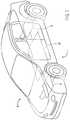
- FIG. 1is a perspective view of an embodiment of an electric vehicle with an integrated powertrain system and an integrated battery system;
- FIG. 2is a perspective view of an embodiment of an electric vehicle battery system
- FIG. 3is a side view of an embodiment of an electric vehicle battery system
- FIG. 4is a sectional view of an embodiment of an electric vehicle battery system within line 4 - 4 of FIG. 2 ;
- FIG. 5is a sectional view of an embodiment of an electric vehicle battery system within line 5 - 5 of FIG. 2 ;
- FIG. 6is a schematic view of an embodiment of an electric vehicle battery system
- FIG. 7is a schematic view of an embodiment of an electric vehicle with the integrated powertrain system.
- FIG. 1is a perspective view of an electric vehicle 2 .
- the electric vehicle 2includes an integrated powertrain system 4 with a front powertrain 6 and a rear powertrain 8 .
- the front powertrain 6drives the front wheels while the rear powertrain 8 drives the rear wheels.
- the powertrain system 4is powered with a battery system 10 that provides power to electric motors in the integrated powertrain system 4 .
- the integrated powertrain system 4 and battery system 10reduces the number of components, wiring complexity, etc. in the electric vehicle 2 .
- the design of the vehicle 2may therefore reduce manufacturing complexity (e.g., number of components, assembly) as well as manufacturing costs.
- FIG. 2is a perspective view of an embodiment of an electric vehicle battery system 10 that reduces the number of components, wiring complexity, etc. in an electric vehicle.
- the vehicle 2includes contactors and connectors within the battery system 10 that are typically placed in different housings and at different locations on vehicle 2 .
- the battery system 10includes a housing 12 with a first battery housing member 14 and a second battery housing member 16 .
- the first and second battery housing members 14 , 16may couple together in a variety of ways including threaded fasteners, welding, etc. to form the housing 12 .
- the battery housing 12houses a variety of components including battery cells 18 (e.g., 1, 2, 3, 4, 5, 10, 15 or more cells), contactors 20 , connectors 22 , wires, sensors, etc. that work together to connect the stored electrical energy in the battery cells 18 to various vehicle systems (e.g., AC compressor, motors, heating system) as well as to recharge the battery cells 18 for future use.
- battery cells 18e.g., 1, 2, 3, 4, 5, 10,
- the battery housing 12may include specially designed sections/portions that may be integrally formed into the housing 12 .
- the sections/portionsmay form sub-housings/compartments for various electrical components within the housing 12 .
- the battery system 10reduces manufacturing complexity by reducing the number of housings needed for electrical components (e.g., connectors for connecting the electrical components in the housings), wiring complexity, as well as the amount of wiring, etc.
- the housing 12includes integral housings/compartments 24 , 26 . These housings/compartments 24 , 26 are at respective ends 28 , 30 of the battery system 10 .
- the housing 12may facilitate connection of the battery system 10 to various systems on the electrical vehicle 2 .
- the housings/compartments 24 , 26may be positioned at other locations on the housing 12 (e.g., center, sides).
- housings/compartments 24 , 26enable integration of a fast charging system 32 (e.g., direct current charging system) and an onboard charger system 34 (e.g., A/C to DC charging system) into the battery system 10 . Accordingly, separate housings, additional connectors, and complex wiring are not needed for the fast charging system 32 and onboard charger system 34 .
- a fast charging system 32e.g., direct current charging system
- an onboard charger system 34e.g., A/C to DC charging system
- FIG. 3is a side view of an embodiment of an electric vehicle battery system 10 .
- the housings/compartments 24 , 26are either integrally formed into or coupled to the first battery housing member 14 .
- the first connector housing 24may be formed with a first connector housing portion 40 and a second connector housing portion 42 .
- the first battery housing member 14 and the first connector housing portion 40are one-piece (e.g., integral).
- the first battery housing member 14 and the first connector housing portion 40couple together with an integral flange 44 to form a gap 46 .
- the gap 46may reduce electromagnetic interference as well as protect the components in the connector housing from the battery cells 18 .
- the second connector housing 42 and the second battery housing member 16are likewise one-piece, which reduces the need to manufacture additional housings to store the components in the connector housing 24 .
- the battery system 10includes a second connector housing 26 .
- the second connector housing 26may be formed out of one-piece with the first battery housing member 14 or may be a separately formed piece that couples to the first battery housing member 14 to form the second connector housing 26 .
- FIG. 4is a sectional view of an embodiment of an electric vehicle battery system 10 within line 4 - 4 of FIG. 2 .
- the first connector housing 24includes a variety of connectors 22 that electrically couple the battery system 10 to the vehicle 2 .
- the first connectoris an onboard charger connector 60 .
- the onboard charger connector 60forms part of the charger system 62 that converts electricity from an A/C source (e.g., A/C outlet at vehicle owner's home) into a direct current for charging the cells 18 .
- the charger system 62includes a connector 64 that converts A/C into DC, which in turn couples to the cells 18 .
- the battery system 10may reduce the number of connectors on the vehicle 2 because the battery system 10 does not couple to a separate housing containing the connector 64 .
- placement of the charger system 62 in the battery housing 12reduces the amount of wiring and the production of a separate housing.
- the fast charger system 68enables the battery system 10 to receive direct current power from a fast charging station. Because a fast charging station transmits significant amounts of electrical power to the vehicle 2 , the connector 66 may have a rating (up to 1200V) to handle the power. Furthermore, to control the flow of power from the fast charging station, the fast charger system may include first and second fast charger contactors 70 , 72 . The first fast charger contactor 70 couples to a positive polarity terminal, while the second fast charger contactor 72 couples to a negative polarity terminal. The first and second fast charger contactors 70 , 72 in turn electrically couple to the battery cells 18 .
- the battery system 10may reduce the number of connectors on the vehicle 2 because the battery system 10 does not couple to a separate housing containing the contactors 70 , 72 . In addition to fewer connectors, placement of the fast charger system 68 in the battery system 10 reduces the amount of wiring and the production of a separate housing.
- the connector housing 24may also include additional high voltage connectors 74 and 76 (e.g., motor connectors) that connect the battery system 10 to one or more converters that transform DC produced by the battery cells 18 into A/C for use by integrated powertrain system 4 (i.e., electric vehicle motors).
- additional high voltage connectors 74 and 76e.g., motor connectors
- a transformer connector 78couples to a transformer 80 that steps down the voltage produced by the battery cells 18 .
- the transformer connector 78is thereby able to transmit low voltage power to the onboard vehicle electronics.
- the transformer 80is within the connector housing 24 which may further reduce wiring, production of a separate housing, and the number of connectors on the vehicle 2 .
- the battery system 10may include one or more sensors 82 .
- the sensors 82may monitor: current flow, voltage, temperature, etc.
- the connector housing 24includes one or more sensor connectors 84 .
- the sensor connector 84enables the sensors 82 to transmit signals to the vehicle's computer that the vehicle's computer uses to monitor and/or control various systems of the electric vehicle 2 .
- FIG. 5is a sectional view of an embodiment of an electric vehicle battery system 10 within line 5 - 5 of FIG. 2 .
- the second connector housing 26may be integrally (e.g., one-piece) formed out of the first battery housing member 14 , which may facilitate manufacturing (e.g., fewer parts, less assembly).
- the second connector housing 26may be separately formed and then coupled to the first battery housing member 14 with fasteners (e.g., threaded fasteners).
- the second connector housing 26includes a variety of connectors 22 that electrically couple the battery system 10 to the vehicle 2 .
- the second connector housing 26may include high voltage connector 100 (e.g., a motor connector) that couples the battery system 10 to the integrated powertrain 4 .
- the second connector housing 26also include a compressor connector 102 and a heater connector 104 .
- the compressor connector 102enables the battery system 10 to provide power to an electric motor that drives a coolant compressor.
- the coolant compressorin turn works with the climate control system to cool the vehicle cabin.
- the heater connector 104also provides power for the climate control system, but instead of cooling the heater connector 104 enables the climate control system to heat the cabin.
- the heater connector 104may couple to a resistance heater that generates heat with the electrical power from the battery system 10 .
- the battery system 10may include one or more sensors 82 .
- the sensors 82may monitor, current flow, voltage, temperature, etc.
- the sensors 82couple to the vehicle's computer, with one or more sensor connectors 84 .
- the sensor connectors 84enable the sensors 82 to transmit signals to the vehicle's computer, which the vehicle's computer uses to monitor and/or control various systems of the electric vehicle 2 .
- the second connector housing 26includes a sensor connector 84 as well.
- the battery system 10may include one or more conduits and/or passages within the housing 12 . These conduits and/or passages enable a temperature controlled fluid to flow through the battery.
- the housing 12provides access to the these conduits and/or passages through a fluid inlet 106 and a fluid outlet 108 .
- the fluid inlet 106 and/or outlet 108may couple to the first battery housing member 14 or the second battery housing member 16 .
- the fluid inlet 106 or the fluid outlet 108may couple to the first battery housing member 14 while the other couples to the second battery housing member 16 .
- FIG. 6is a schematic view of an embodiment of an electric vehicle battery system 10 .
- the battery system 10includes first and second main contactors 120 , 122 that control the flow of electrical power to and from the cells 18 .
- the battery system 10may include one or more sensors 84 (e.g., voltage sensors, current sensors, Hall effect sensors, temperature sensors). These sensors 84 couple to the vehicle computer 126 , which receives and processes the signals.
- the computer 126includes a processor 128 and a memory 130 . In operation, the processor 128 uses instructions stored on the memory 130 to process the signals and to control the various contactors 20 .
- the battery system 10includes additional contactors 70 and 72 that form part of the fast charger system 68 .
- These contactors 70 , 72are integrated into the battery system 10 to facilitate manufacturing and reduce complexity. More specifically, including these contactors in the battery housing 12 reduces the numbers of housings, connectors, wiring, etc.
- an onboard charger system 62may be integrated into the battery housing 12 to facilitate charging of the battery from an A/C source.
- the onboard charger system 62includes a connector 64 that converts A/C power into DC power for charging the cells 18 .
- the battery system 10may also include one or more low power connectors (e.g., connector 78 , connector 102 , and connector 104 ) for powering various vehicle systems (e.g., HVAC, computer).
- Coupled to some or all of these connectorsis one or more transformers 80 that reduce the power from the cells 18 for use by these different vehicle systems.
- the battery system 10controls power to these different connectors using the contactors 120 and 122 as well as one or more relays 132 .
- the relays 132are similarly controlled by the computer 126 .
- Other connectors 22 in the battery system 10include high voltage connectors (e.g., connector 74 , connector 76 , connector 100 ) that transfer power form the battery system 10 to the integrated powertrain system 4 , which uses significant amounts of power to move the vehicle 2 .
- integrating these components into the battery system 10may reduce manufacturing complexity (e.g., wiring, housings, connectors).
- FIG. 7is a schematic bottom view of an embodiment of an electric vehicle 2 with the integrated powertrain system 4 .
- the integrated powertrain system 4includes a front powertrain 6 and a rear powertrain 8 .
- the front and rear powertrains 6 , 8power the respective front and rear wheels 150 , 152 .
- these integrated powertrainsincorporate multiple components into a single housing.
- the rear integrated powertrain 6may incorporate an electric motor, gear reducer, communication lines, cooling system, etc. into a single housing instead of separate housings, wiring, cooling, etc. for each of the electric motors.
- the integrated powertrain system 4is therefore able to reduce the number of components, wiring complexity, etc. in the electric vehicle 2 . With reduced manufacturing complexity (e.g., number of components, assembly) the vehicle 2 may be manufactured at lower costs.
- the rear powertrain 8may include a single housing 154 that houses a first electric motor 156 and a second electric motor 158 .
- the electric motors 156 , 158couple to a transmission 160 that includes a first gear reducer 162 and a second gear reducer 164 .
- the first and second gear reducers 162 , 164in turn couple to a respective rear wheel to increase the torque from the respective electric motors 156 , 158 .
- the housing 154may also include a first inverter 166 and a second inverter 168 that convert direct current (DC) from the battery system 10 into alternating current (A/C) for each of the electric motors 156 , 158 .
- DCdirect current
- A/Calternating current
- Torque vectoringis the ability to vary torque to individual wheels (e.g., rear wheels 152 ). For example, while driving the vehicle 2 is able to adjust the torque to each of the rear wheels 152 to adjust for changing road conditions and associated traction (e.g., one wheel encounters an slick portion on the road). This provides the driver with a more responsive drive.
- the front integrated powertrain 6may be similarly constructed with a single housing that houses an electric motor 172 , an inverter 174 , and a transmission 176 .
- the transmissionmay include third and fourth gear reducers 178 , 180 that transfer power from the single electric motor 172 to the front wheels 150 .
- the front integrated power train 6may constructed similar to the front integrated powertrain 6 . That is the front integrated powertrain 6 may include two electric motors and two inverters in order to provide torque vectoring to the front heels 150 within a single housing.
- the integrated powertrain system 4includes an energy interface unit 182 .
- the energy interface unit 182combines a DC/DC converter 184 and the onboard computer 186 into a single housing that then couples to the housing 154 of the rear integrated powertrain 8 .
Landscapes
- Engineering & Computer Science (AREA)
- Transportation (AREA)
- Mechanical Engineering (AREA)
- Chemical & Material Sciences (AREA)
- Combustion & Propulsion (AREA)
- Power Engineering (AREA)
- Life Sciences & Earth Sciences (AREA)
- Sustainable Development (AREA)
- Sustainable Energy (AREA)
- Electric Propulsion And Braking For Vehicles (AREA)
- Arrangement Or Mounting Of Propulsion Units For Vehicles (AREA)
Abstract
Description
Claims (14)
Priority Applications (4)
| Application Number | Priority Date | Filing Date | Title |
|---|---|---|---|
| US15/675,587US10723211B2 (en) | 2016-09-07 | 2017-08-11 | Integrated powertrain system |
| EP17189819.0AEP3293028A1 (en) | 2016-09-07 | 2017-09-07 | Integrated powertrain system |
| CN201721140733.0UCN207374097U (en) | 2016-09-07 | 2017-09-07 | Powertrain Systems and Electric Vehicles |
| CN201710798812.9ACN107791861A (en) | 2016-09-07 | 2017-09-07 | Integrated powertrain system |
Applications Claiming Priority (2)
| Application Number | Priority Date | Filing Date | Title |
|---|---|---|---|
| US201662384298P | 2016-09-07 | 2016-09-07 | |
| US15/675,587US10723211B2 (en) | 2016-09-07 | 2017-08-11 | Integrated powertrain system |
Publications (2)
| Publication Number | Publication Date |
|---|---|
| US20180065616A1 US20180065616A1 (en) | 2018-03-08 |
| US10723211B2true US10723211B2 (en) | 2020-07-28 |
Family
ID=59811192
Family Applications (1)
| Application Number | Title | Priority Date | Filing Date |
|---|---|---|---|
| US15/675,587ActiveUS10723211B2 (en) | 2016-09-07 | 2017-08-11 | Integrated powertrain system |
Country Status (3)
| Country | Link |
|---|---|
| US (1) | US10723211B2 (en) |
| EP (1) | EP3293028A1 (en) |
| CN (2) | CN107791861A (en) |
Cited By (8)
| Publication number | Priority date | Publication date | Assignee | Title |
|---|---|---|---|---|
| US20220348277A1 (en)* | 2021-04-28 | 2022-11-03 | Ford Global Technologies, Llc | Vehicle chassis with interchangeable performance packages and related methods |
| US11702162B2 (en) | 2021-04-28 | 2023-07-18 | Ford Global Technologies, Llc | Configurable vehicle chassis and associated methods |
| US11807094B1 (en) | 2022-12-02 | 2023-11-07 | Dana Belgium N.V. | Electric drive unit with planetary two-speed powershift transmission driven by three electric motors |
| US11807302B2 (en) | 2021-04-28 | 2023-11-07 | Ford Global Technologies, Llc | Methods and apparatus for scalable vehicle platforms |
| US11866095B2 (en) | 2021-04-28 | 2024-01-09 | Ford Global Technologies, Llc | Multi-position wheel assembly mounts |
| US11938802B2 (en) | 2021-04-28 | 2024-03-26 | Ford Global Technologies, Llc | Electric motorized wheel assemblies |
| US12011962B2 (en) | 2021-04-28 | 2024-06-18 | Ford Global Technologies, Llc | Configurable vehicle frames and associated methods |
| US12071018B2 (en) | 2019-03-08 | 2024-08-27 | Scania Cv Ab | Powertrain for a vehicle and a vehicle consisting the powertrain |
Families Citing this family (3)
| Publication number | Priority date | Publication date | Assignee | Title |
|---|---|---|---|---|
| US10723211B2 (en)* | 2016-09-07 | 2020-07-28 | Thunder Power New Energy Vehicle Development Company Limited | Integrated powertrain system |
| US20180065492A1 (en)* | 2016-09-07 | 2018-03-08 | Thunder Power New Energy Vehicle Development Company Limited | Electric vehicle system |
| DE102020128824A1 (en)* | 2020-11-03 | 2022-05-05 | Bayerische Motoren Werke Aktiengesellschaft | Method and device for actively controlling vibrations in a vehicle with multiple electrical machine units |
Citations (12)
| Publication number | Priority date | Publication date | Assignee | Title |
|---|---|---|---|---|
| US7635039B2 (en)* | 2004-01-13 | 2009-12-22 | Mitsubishi Heavy Industries, Ltd. | Series hybrid electric vehicle |
| EP2258569A2 (en) | 2006-04-03 | 2010-12-08 | BluWav Systems, LLC | Vehicle power unit designed as retrofittable axle comprising electric motors with a connecting clutch |
| EP2697089A2 (en) | 2011-04-14 | 2014-02-19 | Rainer M. Puls | Electric traction drive for electric vehicles |
| US8812182B2 (en)* | 2010-02-05 | 2014-08-19 | Dr. Ing. H.C. F. Porsche Aktiengesellschaft | Control system for a vehicle having two axle drive devices and method for operating a control system |
| WO2014145515A2 (en) | 2013-03-15 | 2014-09-18 | Linamar Corporation | Hybrid axle assembly for a motor vehicle |
| US20150042245A1 (en) | 2012-03-21 | 2015-02-12 | Honda Motor Co., Ltd. | Vehicle driving system and vehicle driving system control method |
| US9030063B2 (en)* | 2010-12-17 | 2015-05-12 | Tesla Motors, Inc. | Thermal management system for use with an integrated motor assembly |
| US9120389B1 (en)* | 2014-02-08 | 2015-09-01 | Atieva, Inc. | Integrated motor assembly with compliantly mounted power inverter |
| US9126500B2 (en)* | 2011-11-24 | 2015-09-08 | Ntn Corporation | Motor control device |
| US9168818B2 (en)* | 2012-02-22 | 2015-10-27 | Ntn Corporation | Electric vehicle |
| US20150328993A1 (en)* | 2014-05-14 | 2015-11-19 | Hyundai Motor Company | Hybrid power control apparatus for vehicle |
| US20160229293A1 (en)* | 2013-09-19 | 2016-08-11 | Toyota Jidosha Kabushiki Kaisha | Electrically driven vehicle |
Family Cites Families (5)
| Publication number | Priority date | Publication date | Assignee | Title |
|---|---|---|---|---|
| FR2998531B1 (en)* | 2012-11-26 | 2016-03-18 | Renault Sas | METHOD AND SYSTEM FOR CONTROLLING A HYBRID VEHICLE WITH INDEPENDENT REVERSE ELECTRIC MOTORS |
| CN103895525B (en)* | 2012-12-28 | 2016-05-18 | 深圳先进技术研究院 | Power-driven system and electric motor car |
| DE102013106085B4 (en)* | 2013-06-12 | 2024-05-23 | Dr. Ing. H.C. F. Porsche Aktiengesellschaft | Bearing frame for an electrically powered motor vehicle |
| CN105329080A (en)* | 2015-11-23 | 2016-02-17 | 十堰精密制造有限公司 | Electrically driven rear axle assembly for electric vehicle |
| US10723211B2 (en)* | 2016-09-07 | 2020-07-28 | Thunder Power New Energy Vehicle Development Company Limited | Integrated powertrain system |
- 2017
- 2017-08-11USUS15/675,587patent/US10723211B2/enactiveActive
- 2017-09-07CNCN201710798812.9Apatent/CN107791861A/enactivePending
- 2017-09-07EPEP17189819.0Apatent/EP3293028A1/ennot_activeWithdrawn
- 2017-09-07CNCN201721140733.0Upatent/CN207374097U/ennot_activeExpired - Fee Related
Patent Citations (14)
| Publication number | Priority date | Publication date | Assignee | Title |
|---|---|---|---|---|
| US7635039B2 (en)* | 2004-01-13 | 2009-12-22 | Mitsubishi Heavy Industries, Ltd. | Series hybrid electric vehicle |
| EP2258569A2 (en) | 2006-04-03 | 2010-12-08 | BluWav Systems, LLC | Vehicle power unit designed as retrofittable axle comprising electric motors with a connecting clutch |
| US8812182B2 (en)* | 2010-02-05 | 2014-08-19 | Dr. Ing. H.C. F. Porsche Aktiengesellschaft | Control system for a vehicle having two axle drive devices and method for operating a control system |
| US9030063B2 (en)* | 2010-12-17 | 2015-05-12 | Tesla Motors, Inc. | Thermal management system for use with an integrated motor assembly |
| US9692277B2 (en)* | 2010-12-17 | 2017-06-27 | Tesla, Inc. | Integrated electric motor assembly |
| EP2697089A2 (en) | 2011-04-14 | 2014-02-19 | Rainer M. Puls | Electric traction drive for electric vehicles |
| US9126500B2 (en)* | 2011-11-24 | 2015-09-08 | Ntn Corporation | Motor control device |
| US9168818B2 (en)* | 2012-02-22 | 2015-10-27 | Ntn Corporation | Electric vehicle |
| US20150042245A1 (en) | 2012-03-21 | 2015-02-12 | Honda Motor Co., Ltd. | Vehicle driving system and vehicle driving system control method |
| WO2014145515A2 (en) | 2013-03-15 | 2014-09-18 | Linamar Corporation | Hybrid axle assembly for a motor vehicle |
| US20160039277A1 (en)* | 2013-03-15 | 2016-02-11 | Adrian Quintana | Hybrid Axle Assembly For A Motor Vehicle |
| US20160229293A1 (en)* | 2013-09-19 | 2016-08-11 | Toyota Jidosha Kabushiki Kaisha | Electrically driven vehicle |
| US9120389B1 (en)* | 2014-02-08 | 2015-09-01 | Atieva, Inc. | Integrated motor assembly with compliantly mounted power inverter |
| US20150328993A1 (en)* | 2014-05-14 | 2015-11-19 | Hyundai Motor Company | Hybrid power control apparatus for vehicle |
Non-Patent Citations (1)
| Title |
|---|
| European Search Report for EP 17189819 dated Jan. 15, 2018, all pages. |
Cited By (11)
| Publication number | Priority date | Publication date | Assignee | Title |
|---|---|---|---|---|
| US12071018B2 (en) | 2019-03-08 | 2024-08-27 | Scania Cv Ab | Powertrain for a vehicle and a vehicle consisting the powertrain |
| US20220348277A1 (en)* | 2021-04-28 | 2022-11-03 | Ford Global Technologies, Llc | Vehicle chassis with interchangeable performance packages and related methods |
| US11702162B2 (en) | 2021-04-28 | 2023-07-18 | Ford Global Technologies, Llc | Configurable vehicle chassis and associated methods |
| US11807302B2 (en) | 2021-04-28 | 2023-11-07 | Ford Global Technologies, Llc | Methods and apparatus for scalable vehicle platforms |
| US11858571B2 (en)* | 2021-04-28 | 2024-01-02 | Ford Global Technologies, Llc | Vehicle chassis with interchangeable performance packages and related methods |
| US11866095B2 (en) | 2021-04-28 | 2024-01-09 | Ford Global Technologies, Llc | Multi-position wheel assembly mounts |
| US11938802B2 (en) | 2021-04-28 | 2024-03-26 | Ford Global Technologies, Llc | Electric motorized wheel assemblies |
| US12011962B2 (en) | 2021-04-28 | 2024-06-18 | Ford Global Technologies, Llc | Configurable vehicle frames and associated methods |
| US12195120B2 (en) | 2021-04-28 | 2025-01-14 | Ford Global Technologies, Llc | Configurable vehicle chassis and associated methods |
| US12420878B2 (en) | 2021-04-28 | 2025-09-23 | Ford Global Technologies, Llc | Vehicle chassis with interchangeable performance packages and related methods |
| US11807094B1 (en) | 2022-12-02 | 2023-11-07 | Dana Belgium N.V. | Electric drive unit with planetary two-speed powershift transmission driven by three electric motors |
Also Published As
| Publication number | Publication date |
|---|---|
| CN207374097U (en) | 2018-05-18 |
| CN107791861A (en) | 2018-03-13 |
| EP3293028A1 (en) | 2018-03-14 |
| US20180065616A1 (en) | 2018-03-08 |
Similar Documents
| Publication | Publication Date | Title |
|---|---|---|
| US10723211B2 (en) | Integrated powertrain system | |
| US20180069425A1 (en) | Electric vehicle system | |
| US20180065492A1 (en) | Electric vehicle system | |
| US11014451B2 (en) | Reconfigurable electrical power conversion system | |
| CN106450981B (en) | Bus bar for power module assembly | |
| US20130241486A1 (en) | Power control unit for electric vehicle | |
| US20120161698A1 (en) | Method and system for charging a vehicle high voltage battery | |
| EP2672600A2 (en) | System for transferring energy from an energy source and method of making same | |
| CN105633450B (en) | Traction battery assembly with snap-in bus bar module | |
| CN104934656A (en) | Traction battery thermal management system | |
| CN112951780A (en) | Electronic power module assembly and control logic with direct cooling heat pipe system | |
| US10181765B2 (en) | Thermal management assembly for an electrified vehicle | |
| US20120235640A1 (en) | Energy management systems and methods | |
| CN106058090A (en) | Traction battery assembly | |
| US10005366B1 (en) | Powertrain with high-power distribution module and high-current ring terminal connection for the same | |
| CN114512772A (en) | Bus electrical center with direct contactor installation | |
| CN201227959Y (en) | Integrated machine controller and dc-dc converter for miniature electric motor vehicle | |
| US12115869B2 (en) | Current control during DC fast charging | |
| KR20130131297A (en) | Battery charger for powering drive motors of cars | |
| JP7656253B2 (en) | Electronic equipment module and power supply system | |
| CN106207026B (en) | Step structure for traction battery shell | |
| Hassan et al. | Development and installation of battery-powered electric vehicle wiring system | |
| CN220964675U (en) | Motor controller, electric drive device, electric drive system and electric equipment | |
| CN109969021B (en) | Vehicle charging system including phase change material for absorbing heat during a charging event | |
| JP6439976B2 (en) | Non-contact power supply battery device |
Legal Events
| Date | Code | Title | Description |
|---|---|---|---|
| AS | Assignment | Owner name:THUNDER POWER NEW ENERGY VEHICLE DEVELOPMENT COMPANY LIMITED, HONG KONG Free format text:ASSIGNMENT OF ASSIGNORS INTEREST;ASSIGNOR:MASTRANDREA, FRANCESCO;REEL/FRAME:043273/0413 Effective date:20170811 Owner name:THUNDER POWER NEW ENERGY VEHICLE DEVELOPMENT COMPA Free format text:ASSIGNMENT OF ASSIGNORS INTEREST;ASSIGNOR:MASTRANDREA, FRANCESCO;REEL/FRAME:043273/0413 Effective date:20170811 | |
| STPP | Information on status: patent application and granting procedure in general | Free format text:NON FINAL ACTION MAILED | |
| STPP | Information on status: patent application and granting procedure in general | Free format text:RESPONSE TO NON-FINAL OFFICE ACTION ENTERED AND FORWARDED TO EXAMINER | |
| STPP | Information on status: patent application and granting procedure in general | Free format text:FINAL REJECTION MAILED | |
| STPP | Information on status: patent application and granting procedure in general | Free format text:DOCKETED NEW CASE - READY FOR EXAMINATION | |
| STPP | Information on status: patent application and granting procedure in general | Free format text:NOTICE OF ALLOWANCE MAILED -- APPLICATION RECEIVED IN OFFICE OF PUBLICATIONS | |
| STPP | Information on status: patent application and granting procedure in general | Free format text:PUBLICATIONS -- ISSUE FEE PAYMENT VERIFIED | |
| STCF | Information on status: patent grant | Free format text:PATENTED CASE | |
| MAFP | Maintenance fee payment | Free format text:PAYMENT OF MAINTENANCE FEE, 4TH YR, SMALL ENTITY (ORIGINAL EVENT CODE: M2551); ENTITY STATUS OF PATENT OWNER: SMALL ENTITY Year of fee payment:4 |