US10722959B2 - Table saw - Google Patents
Table sawDownload PDFInfo
- Publication number
- US10722959B2 US10722959B2US15/168,598US201615168598AUS10722959B2US 10722959 B2US10722959 B2US 10722959B2US 201615168598 AUS201615168598 AUS 201615168598AUS 10722959 B2US10722959 B2US 10722959B2
- Authority
- US
- United States
- Prior art keywords
- elevation
- tilt
- blade
- carriage
- gear
- Prior art date
- Legal status (The legal status is an assumption and is not a legal conclusion. Google has not performed a legal analysis and makes no representation as to the accuracy of the status listed.)
- Active, expires
Links
Images


Classifications
- B—PERFORMING OPERATIONS; TRANSPORTING
- B23—MACHINE TOOLS; METAL-WORKING NOT OTHERWISE PROVIDED FOR
- B23D—PLANING; SLOTTING; SHEARING; BROACHING; SAWING; FILING; SCRAPING; LIKE OPERATIONS FOR WORKING METAL BY REMOVING MATERIAL, NOT OTHERWISE PROVIDED FOR
- B23D45/00—Sawing machines or sawing devices with circular saw blades or with friction saw discs
- B23D45/06—Sawing machines or sawing devices with circular saw blades or with friction saw discs with a circular saw blade arranged underneath a stationary work-table
- B23D45/061—Sawing machines or sawing devices with circular saw blades or with friction saw discs with a circular saw blade arranged underneath a stationary work-table the saw blade being mounted on a carriage
- B23D45/062—Sawing machines or sawing devices with circular saw blades or with friction saw discs with a circular saw blade arranged underneath a stationary work-table the saw blade being mounted on a carriage the saw blade being adjustable according to depth or angle of cut
- B—PERFORMING OPERATIONS; TRANSPORTING
- B27—WORKING OR PRESERVING WOOD OR SIMILAR MATERIAL; NAILING OR STAPLING MACHINES IN GENERAL
- B27G—ACCESSORY MACHINES OR APPARATUS FOR WORKING WOOD OR SIMILAR MATERIALS; TOOLS FOR WORKING WOOD OR SIMILAR MATERIALS; SAFETY DEVICES FOR WOOD WORKING MACHINES OR TOOLS
- B27G19/00—Safety guards or devices specially adapted for wood saws; Auxiliary devices facilitating proper operation of wood saws
- B27G19/08—Accessories for keeping open the saw kerf, e.g. riving knives or wedge plates
Definitions
- the present disclosurerelates to power tools and particularly to power tools with tool positioning mechanisms.
- Power toolsoften include some type of elevation mechanism to adjust the height or position of a cutter.
- an elevation mechanismallows the height of the blade to be adjusted and a tilt mechanism allows the angle/tilt of the blade to be adjusted.
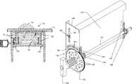
- FIG. 1shows a table saw with an elevation mechanism.
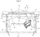
- FIGS. 2-4show a table saw with an indexable elevation mechanism.
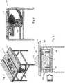
- FIG. 5shows a detailed view of an indexable elevation mechanism.
- FIG. 6shows a sectional view of a sliding connection between an elevation carriage and a bracket.
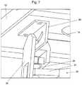
- FIG. 7shows tilt a tilt plate connection
- FIGS. 8 and 9show sectional detailed views of an indexable elevation mechanism.
- FIGS. 10-13show an indexable tilt system.
- FIGS. 14-16show an alternative indexable tilt system with enhanced index resolution.
- FIG. 1shows a table saw 10 having a table 12 with an opening 14 and a blade 16 projecting through opening 14 .
- Blade 16is supported on an arbor 18 mounted in an elevation carriage 20 .
- a riving knife 22is also mounted to elevation carriage 20 .
- Elevation carriage 20has front and rear support arms 24 , 26 that threadedly engage on front and rear threaded shafts 28 , 30 .
- Rotation of shafts 28 , 30 by elevation control shaft 32 via miter gears 34causes elevation carriage 20 to move up and down shafts 28 , 30 .
- Shafts 28 , 30are supported by front and rear brackets 36 , 38 respectively.
- Brackets 36 , 38are pivotally connected to table 12 via tilt plates 40 , 42 , respectively, which allow elevation carriage 20 (and thereby blade 16 ) to tilt relative to table 12 .
- Representative tilt plate 40is shown in more detail in FIG. 7 .
- Tilt plates 40 and 42 , elevation carriage 20 , support arms 24 , 26 , shafts 28 , 30 , elevation control shaft 32 , miter gears 34 , and brackets 36 , 38comprise an example of a trunnion assembly, shown generally at 43 in FIG. 1 .
- FIGS. 2-4shows a saw 110 having a table 112 with an opening 114 and a blade 116 projecting through opening 114 .
- Blade 116is supported on an arbor 118 mounted in an elevation carriage 120 .
- Elevation carriage 120has front and rear support arms 124 , 126 that slideably engage front and rear brackets 136 , 138 , respectively.
- Brackets 136 , 138are pivotally connected to table 112 via tilt plates like tilt plates 40 and 42 , which allow elevation carriage 120 (and thereby blade 16 ) to tilt relative to table 112 .
- Elevation carriage 120is driven up and down on brackets 136 , 138 by the interaction of front and rear elevation pinions 144 , 146 with front and rear racks 168 , 170 secured to elevation carriage 120 .
- Elevation pinions 144 , 146are mounted to elevation control shaft 132 .
- Rotating elevation control shaft 132 with elevation handle 152drives elevation carriage 120 up and down brackets, such as bracket 148 , to control the elevation of blade 116 through opening 114 .
- a strap, chain or other similar member wrapped around elevation shaft 132 or crank arm attached thereto,could likewise be used to convert rotational movement of elevation shaft to vertical displacement of elevation carriage 120 .
- elevation carriage 120is shown with the direct torque transfer configuration illustrated in FIG. 1 , the elevation mechanism is equally applicable to more traditionally constructed trunnion or elevation assemblies.
- FIG. 5illustrates bracket 148 in more detail with the addition of an indexable control 154 for elevation control shaft 132 .
- Bracket 148includes guide two slots 156 (the lower one being obscured by the indexable control).
- a guide assembly 158is secured to elevation carriage 120 and rides in each slot 156 .
- each guide assemblyincludes a screw 160 , a bushing 162 and washers 164 to provide structure to slideably retain elevation carriage 120 to bracket 148 .
- Guide assemblies 158are preferably a relatively close fit in slots 156 to provide accurate and slop free linear motion of elevation carriage 120 on brackets 148 , 150 .
- Elevation carriage 120may also be thought of as a unified trunnion/elevation carriage since it serves the purpose of the trunnion link as well as the elevation carriage.
- Indexable control 154 shown in FIG. 5includes an indexing gear 180 connected to handle 152 and adapted to rotate with shaft 132 .
- Indexing gear 180includes teeth 182 disposed around the perimeter adapted to selectively mesh with teeth 184 formed on indexing rack 186 .
- Handle 152 and gear 180are secured together and slideably mounted on shaft 132 as shown in FIGS. 8 and 9 . More particularly, handle 152 has a central bore 188 that fits slideably over shaft 132 and is held in place by a screw 190 , washer 192 and spring 194 at one end and a cross pin 198 fixed through shaft 132 ridding in a slot-like pocket 196 .
- the finite pitch of teeth 184 , 182only allows the elevation shaft to lock at indexed locations.
- the pitch of the teeth in conjunction with the diameter of the pinionswill result in a specific blade elevation change per tooth.
- Typical dimensionsare chosen to generate an incremental elevation change of approximately 1/32 nd of an inch and full up to full down elevation change with a single revolution.
- Other valuesare equally within the scope of the invention and the specifics are chosen based on the desired operating characteristics of the saw. For instance, it may be desirable in some applications to have finer elevation adjustments and or more or less handle turns to raise or lower the blade.
- gear and rackcould be replaced with corresponding untoothed components that locked by frictional engagement, such as a taper lock, to eliminate the indexing feature while still allowing fast and simple elevation adjustment.
- gear 180could be replaced with a single pointer that engaged teeth on rack 186 —although this might require rack 186 to be extended to allow a greater range of elevation adjustment.
- rack 186could be replaced with a single point that could selectively engage gear 180 .
- indexing control 200includes a tilt indexing gear 202 with teeth 204 distributed around the perimeter.
- a central bore 206fits over the elevation shaft (not shown) so that gear 202 can rotate independently of the elevation shaft.
- Gear 202fits into an arcuate slot 208 between an upper rack 210 and a lower rack 212 .
- Slot 208 and racks 210 , 212are preferably molded in a plastic housing 214 forming part of the enclosure of the saw.
- One of racks 210 , 212is displaced forward or rearward relative to the other so that gear 202 can be shifted forward or back to selectively engage one or both racks.
- Control 300includes a stepped tilt indexing gear 302 .
- Gear 302includes a small gear 304 and a large gear 306 secured to rotate together.
- Small gear 304is positioned to interact with upper arc 308 while large gear 306 selectively meshes with lower arc 310 .
- Elevation positioning gear 312includes a hub 316 . Stepped gear 302 fits over hub 316 , and is thereby supported by the hub while gear 302 remains free to rotate around the hub.
- Hub 316is slideably mounted to an elevation shaft 318 and positioned by two pins 320 press fit into holes 322 formed in shaft 318 .
- a spring 324is captured between the pins and fits in cavity 326 .
- the ends of cavity 326are sized to allow shaft 318 to slide but catch spring 324 .
- spring 324is compressed, but allows the assembly to slide back and forth by a small amount. The spring also restores the assembly to a neutral position (shown in FIG. 14 ) when the handle is released.
- both the tilt and elevationare locked because small gear 304 meshes with upper arc 308 , large gear 306 meshes with lower arc 310 and gear 312 meshes with rack 314 .
- elevation positioning gear 312is disengaged from rack 314 allowing handle 328 to be rotated to raise and lower the blade, while gears 304 , 306 still mesh with arcs 308 , 310 locking the tilt of the blade in place. If, on the other hand, handle 328 is pulled out, as depicted in FIG.
- elevation positioning gear 312remains engaged with rack 314 , but large gear 306 comes disengaged from rack 310 , which allows the blade to tilt by rolling of small gear 304 on rack 308 .
- the bladecan be tilted by simply moving the handle to one side or the other without rotating the handle. On first inspection, this is very similar to the system of FIGS. 10-13 , however, the use of a step gear causes the indexing to occur at smaller intervals for a given tooth size and arc radius. This is advantageous to provide the ability to set the tilt in finer increments and/or to allow for the use of larger teeth which may reengage more easily or be more robust.
- the indexing control system of FIG. 14-16provides the advantage of a single handle and one handed control of both tilt and elevation in a table saw. There is no need to release a clamp or other mechanism to release the system to tilt or elevate the blade. The system is nonetheless robustly held in place when the handle is not pushed or pulled. The system is also very mechanically simple and economical to construct.
Landscapes
- Life Sciences & Earth Sciences (AREA)
- Engineering & Computer Science (AREA)
- Mechanical Engineering (AREA)
- Wood Science & Technology (AREA)
- Forests & Forestry (AREA)
- Sawing (AREA)
Abstract
Description
Claims (2)
Priority Applications (1)
| Application Number | Priority Date | Filing Date | Title |
|---|---|---|---|
| US15/168,598US10722959B2 (en) | 2015-06-01 | 2016-05-31 | Table saw |
Applications Claiming Priority (2)
| Application Number | Priority Date | Filing Date | Title |
|---|---|---|---|
| US201562169386P | 2015-06-01 | 2015-06-01 | |
| US15/168,598US10722959B2 (en) | 2015-06-01 | 2016-05-31 | Table saw |
Publications (2)
| Publication Number | Publication Date |
|---|---|
| US20160346849A1 US20160346849A1 (en) | 2016-12-01 |
| US10722959B2true US10722959B2 (en) | 2020-07-28 |
Family
ID=57397501
Family Applications (1)
| Application Number | Title | Priority Date | Filing Date |
|---|---|---|---|
| US15/168,598Active2036-06-01US10722959B2 (en) | 2015-06-01 | 2016-05-31 | Table saw |
Country Status (1)
| Country | Link |
|---|---|
| US (1) | US10722959B2 (en) |
Families Citing this family (7)
| Publication number | Priority date | Publication date | Assignee | Title |
|---|---|---|---|---|
| US9724840B2 (en) | 1999-10-01 | 2017-08-08 | Sd3, Llc | Safety systems for power equipment |
| US9927796B2 (en) | 2001-05-17 | 2018-03-27 | Sawstop Holding Llc | Band saw with improved safety system |
| US7707920B2 (en)* | 2003-12-31 | 2010-05-04 | Sd3, Llc | Table saws with safety systems |
| US10933554B2 (en)* | 2017-05-25 | 2021-03-02 | Sawstop Holding Llc | Power saws |
| CN111051009B (en) | 2017-08-30 | 2023-06-16 | 米沃奇电动工具公司 | Power Tools with Object Detection |
| CN110181117A (en)* | 2018-02-24 | 2019-08-30 | 蒋国平 | A kind of oil smoke machining screw drive adjustable type multi-angle cutting apparatus |
| CN110153734A (en)* | 2018-02-24 | 2019-08-23 | 蒋国平 | A kind of oil smoke machining limit-type multi-angle cutting apparatus of nut |
Citations (27)
| Publication number | Priority date | Publication date | Assignee | Title |
|---|---|---|---|---|
| US2265407A (en) | 1939-01-25 | 1941-12-09 | Delta Mfg Co | Tilting arbor saw |
| US2974693A (en) | 1958-05-22 | 1961-03-14 | Yuba Cons Ind Inc | Sliding table saw |
| US3115166A (en)* | 1958-05-22 | 1963-12-24 | Magna Corp | Sliding table saw |
| US4249442A (en) | 1979-07-25 | 1981-02-10 | Black & Decker Inc. | Elevation setting mechanism for a table saw and the like |
| US4516612A (en)* | 1982-09-03 | 1985-05-14 | Wiley Edward R | Multipurpose table saw |
| US5230269A (en) | 1988-12-30 | 1993-07-27 | Ryobi Limited | Table saw |
| WO2001026064A2 (en) | 1999-10-01 | 2001-04-12 | Sd3, Llc | Safety systems for power equipment |
| EP1110650A1 (en) | 1999-12-21 | 2001-06-27 | SCM GROUP S.p.A. | Saw blade positioning system for table saw |
| CA2330872A1 (en)* | 2000-02-01 | 2001-08-01 | Emerson Electric Co. | Table saw |
| US6530303B1 (en)* | 1999-06-10 | 2003-03-11 | Black & Decker Inc. | Table saw |
| US6722242B2 (en) | 2001-12-05 | 2004-04-20 | Bor Yann Chuang | Transmission device of a table saw |
| US20040226800A1 (en) | 2003-05-13 | 2004-11-18 | Credo Technology Corporation. | Safety detection and protection system for power tools |
| US6994004B2 (en) | 2000-09-29 | 2006-02-07 | Sd3, Llc | Table saw with improved safety system |
| US20060201296A1 (en)* | 2005-03-10 | 2006-09-14 | Sheng-Hsien Kuo | Woodworking table with an auxiliary device |
| US7350444B2 (en) | 2000-08-14 | 2008-04-01 | Sd3, Llc | Table saw with improved safety system |
| US20080289469A1 (en)* | 2007-05-24 | 2008-11-27 | Bor-Yann Chuang | Sawing angle sensing device for a sawing machine |
| US20100005939A1 (en) | 2008-07-08 | 2010-01-14 | Burke Jeremy J | Table Saw |
| US20100050843A1 (en) | 2008-08-18 | 2010-03-04 | Gass Stephen F | Table saw |
| US7707920B2 (en) | 2003-12-31 | 2010-05-04 | Sd3, Llc | Table saws with safety systems |
| WO2010059786A1 (en) | 2008-11-19 | 2010-05-27 | Power Tool Institute | Safety mechanisms for power tools |
| US20110041667A1 (en)* | 2009-08-20 | 2011-02-24 | Pei-Fang Chiang | Mechanism for adjusting blade height of bench saw |
| US20110146470A1 (en) | 2009-12-17 | 2011-06-23 | Kun-Yen Lin | Woodworking Machine with Sensing Device |
| US20120006171A1 (en) | 2010-07-07 | 2012-01-12 | Durq Machinery Corp. | Saw assembly with safety shield for table saw |
| US20120204688A1 (en)* | 2010-08-12 | 2012-08-16 | Rowe James T | Table miter saw |
| US20140260869A1 (en) | 2013-03-13 | 2014-09-18 | Robert Bosch Gmbh | Height adjustment mechanism for power tool |
| US9555491B2 (en) | 2012-07-20 | 2017-01-31 | Sd3, Llc | Blade elevation mechanisms and anti-backdrive mechanisms for table saws |
| US9844891B2 (en) | 2012-07-20 | 2017-12-19 | Sawstop Holding Llc | Blade tilt mechanisms for table saws |
- 2016
- 2016-05-31USUS15/168,598patent/US10722959B2/enactiveActive
Patent Citations (29)
| Publication number | Priority date | Publication date | Assignee | Title |
|---|---|---|---|---|
| US2265407A (en) | 1939-01-25 | 1941-12-09 | Delta Mfg Co | Tilting arbor saw |
| US2974693A (en) | 1958-05-22 | 1961-03-14 | Yuba Cons Ind Inc | Sliding table saw |
| US3115166A (en)* | 1958-05-22 | 1963-12-24 | Magna Corp | Sliding table saw |
| US4249442A (en) | 1979-07-25 | 1981-02-10 | Black & Decker Inc. | Elevation setting mechanism for a table saw and the like |
| US4516612A (en)* | 1982-09-03 | 1985-05-14 | Wiley Edward R | Multipurpose table saw |
| US5230269A (en) | 1988-12-30 | 1993-07-27 | Ryobi Limited | Table saw |
| US6530303B1 (en)* | 1999-06-10 | 2003-03-11 | Black & Decker Inc. | Table saw |
| WO2001026064A2 (en) | 1999-10-01 | 2001-04-12 | Sd3, Llc | Safety systems for power equipment |
| EP1110650A1 (en) | 1999-12-21 | 2001-06-27 | SCM GROUP S.p.A. | Saw blade positioning system for table saw |
| CA2330872A1 (en)* | 2000-02-01 | 2001-08-01 | Emerson Electric Co. | Table saw |
| US6986370B1 (en) | 2000-02-01 | 2006-01-17 | Home Depot U.S.A., Inc. | Table saw |
| US7350444B2 (en) | 2000-08-14 | 2008-04-01 | Sd3, Llc | Table saw with improved safety system |
| US6994004B2 (en) | 2000-09-29 | 2006-02-07 | Sd3, Llc | Table saw with improved safety system |
| US6722242B2 (en) | 2001-12-05 | 2004-04-20 | Bor Yann Chuang | Transmission device of a table saw |
| US20040226800A1 (en) | 2003-05-13 | 2004-11-18 | Credo Technology Corporation. | Safety detection and protection system for power tools |
| US7827893B2 (en) | 2003-12-31 | 2010-11-09 | Sd3, Llc | Elevation mechanism for table saws |
| US7707920B2 (en) | 2003-12-31 | 2010-05-04 | Sd3, Llc | Table saws with safety systems |
| US20060201296A1 (en)* | 2005-03-10 | 2006-09-14 | Sheng-Hsien Kuo | Woodworking table with an auxiliary device |
| US20080289469A1 (en)* | 2007-05-24 | 2008-11-27 | Bor-Yann Chuang | Sawing angle sensing device for a sawing machine |
| US20100005939A1 (en) | 2008-07-08 | 2010-01-14 | Burke Jeremy J | Table Saw |
| US20100050843A1 (en) | 2008-08-18 | 2010-03-04 | Gass Stephen F | Table saw |
| WO2010059786A1 (en) | 2008-11-19 | 2010-05-27 | Power Tool Institute | Safety mechanisms for power tools |
| US20110041667A1 (en)* | 2009-08-20 | 2011-02-24 | Pei-Fang Chiang | Mechanism for adjusting blade height of bench saw |
| US20110146470A1 (en) | 2009-12-17 | 2011-06-23 | Kun-Yen Lin | Woodworking Machine with Sensing Device |
| US20120006171A1 (en) | 2010-07-07 | 2012-01-12 | Durq Machinery Corp. | Saw assembly with safety shield for table saw |
| US20120204688A1 (en)* | 2010-08-12 | 2012-08-16 | Rowe James T | Table miter saw |
| US9555491B2 (en) | 2012-07-20 | 2017-01-31 | Sd3, Llc | Blade elevation mechanisms and anti-backdrive mechanisms for table saws |
| US9844891B2 (en) | 2012-07-20 | 2017-12-19 | Sawstop Holding Llc | Blade tilt mechanisms for table saws |
| US20140260869A1 (en) | 2013-03-13 | 2014-09-18 | Robert Bosch Gmbh | Height adjustment mechanism for power tool |
Non-Patent Citations (60)
| Title |
|---|
| Altendorf publication, Wilhelm Altendorf GmbH & Co. KG, Minden, Germany, 1999. |
| Bosch 10″ Table Saw Model 0601476139 Parts List and Technical Bulletin, S-B Power Tool Company, Apr. 2001. |
| Bosch 4100 Table Saw Manual, Robert Bosch Tool Corporation, May 2008. |
| Bosch 4100 Table Saw Parts List, Robert Bosch Tool Corporation, Feb. 14, 2008. |
| Bosch Model 4000 Worksite Table Saw Operating/Safety Instructions, S-B Power Tool Company, Jul. 2000. |
| C10RB Jobsite Table Saw Manual, Hitachi Koki USA Ltd., 2006. |
| Craftsman® Power and Hand Tools, pp. 142-143, 2003. |
| Delta 10″ Left Tilting Unisaw Instruction Manual, Delta Machinery, Jan. 2010. |
| Dewalt Models DWE7490, DWE7491 Instruction Manual, Dewalt Industrial Tool Co., 2013. |
| DeWalt Woodworker's Table Saw DW746 Instruction Manual, DeWalt Industrial Tool Co., 2000. |
| DW745 Heavy-Duty 10″ Job Site Table Saw Manual, DeWalt Industrial Tool Co., 2006. |
| DW745 Type 1 Table Saw Parts List, DeWalt Industrial Tool Co., 2005. |
| Engineering Considerations and Terminology, American Linear Manufacturers, date unknown. |
| General Model 50-200R Setup and Operation Manual, General International, Sep. 2010. |
| General Model 502-70 Setup and Operation Manual, General International, Mar. 2010. |
| General Model 50-300/305 MI, 50-300CE/305CE Setup and Operation Manual, General International, Jul. 2009. |
| Grizzly Industrial, Inc. Heavy-Duty 12″ Table Saw Model G5959 and G9957 Parts List, 1998 and Oct. 2001. |
| Grizzly Industrial, Inc. Model G0605X/G0606X Extreme Series 12″ Table Saw Owner's Manual, Grizzly Industrial, Inc., Oct. 2006. |
| Grizzly Industrial, Inc. Model G0651/G0652 10″ Extreme Series Table Saws Owner's Manual, Grizzly Industrial, Inc., Mar. 2008. |
| Inca 2100SE Professional Tablesaw Owners Manual, Injecta Machinery, 1992. |
| Inca 2200 Table Saw Photo of Internal Mechanisms, around 1992. |
| JET XACTA Saw Deluxe Operating Instructions and Parts Manual, JET/Walter Meier Manufacturing Inc., Dec. 2009. |
| Laguna Tools Signature Series by Knapp, Oct. 21, 2002. |
| Laguna Tools table saw owner's manual, date unknown. |
| Makita Model 2704 Exploded Drawings and Parts List, Nov. 2005. |
| Makita Table Saw 2704 Instruction Manual, Makita Corporation of America, date unknown. |
| Porter Cable 10″ Portable Table Saw Model 3812 Parts List with Guard Exploded View, 2005. |
| Porter-Cable 10″ Portable Table Saw 3812, Porter-Cable Corporation, 2005. |
| Porter-Cable Double Insulated 10″ Bench Top Table Saw Instruction Manual, Porter-Cable Corporation, Sep. 15, 2003. |
| Powermatic 10″ Tilting Arbor Saw Model 66 Instruction Manual & Parts List, JET Equipment & Tools, Jun. 2001. |
| Powermatic WMH Tool Group Operating Instructions and Parts Manual 10-inch Cabinet Saw Model 2000, Nov. 2005. |
| Ridgid TS3650 Operators Manual 10″ Cast Iron Table Saw, May 2003, Jun. 2003 and Jul. 15, 2003. |
| Rojek Circular Saw PK 300 Spare part catalogue, Apr. 14, 2003. |
| Rojek KPF 300A-xxxx-RN-1P3 Table Saw/Shaper Combination Machine specification sheet, Sep. 30, 2002. |
| Ryobi 10″ Table Saw BT3000 Operator's Manual, Ryobi Technologies, Inc., Mar. 2001. |
| Ryobi 10″ Table Saw BT3100 Operator's Manual, Ryobi Technologies, Inc., Aug. 2002. |
| SawStop 10″ Contractor Saw Owner's Manual, SawStop, LLC, May 2010. |
| SawStop 10″ Industrial Cabinet Saw Owner's Manual, SawStop, LLC, Oct. 2008. |
| SawStop Model PCS175 10″ Professional Cabinet Saw Owner's Manual, SawStop, LLC, Nov. 2012. |
| SC 3W Circular Saw Manual, SCM Group S.p.A Divisione Minimax-Samco, Feb. 2001. |
| SC 3W Circular Saw Manual, SCM Group S.p.A Divisione Minimax—Samco, Feb. 2001. |
| SCM Group publication, Rimini, Italy, undated. |
| SCM SI 450 Circular saw with tilting blade product brochure, Villa Verucchio, Italy, undated. |
| SI16WA-WF Circular Saw with Tilting Blade Spare Parts Catalogue, SCMI Corporation, Norcross, GA, Nov. 1986 and 1991. |
| SI300N Circular with Tilting Blade Spare Parts Catalogue, SCM, Jun. 12, 2000. |
| SI300S-SI300S4 Circular with Tilting Blade Spare Parts Catalogue, SCM, Oct. 30, 2003. |
| SI320 Circular with Tilting Blade Spare Parts Catalogue, SCM, Dec. 23, 1998. |
| SI3200/3800 Circular with Tilting Blade Spare Parts Catalogue, SCM, Dec. 23, 1998. |
| SI400N Circular with Tilting Blade Spare Parts Catalogue, SCM, Sep. 19, 2000. |
| SI450E Circular with Tilting Blade Spare Parts Catalogue, SCM, Apr. 26, 2001. |
| Skil Model 3400 Table Saw Operating/Safety Instructions, S-B Power Tool Co., Sep. 2001. |
| Skil Model 3400-Type 1 10″ Table Saw Parts List and Technical Bulletin, S-B Power Tool Company, Jun. 1993. |
| Skil Model 3400—Type 1 10″ Table Saw Parts List and Technical Bulletin, S-B Power Tool Company, Jun. 1993. |
| Speed Reducer Self-Locking and Back-Driving, SE Encore, date unknown. |
| The Legendary Shopsmith Mark V ad, Shopsmith, Inc., at least as early as Jan. 14, 2004. |
| TS 250 Circular Saw Parts List, Metabo, 2007. |
| TS 250 Manual, Metabo, 2007. |
| Whirlwind Model 212 Cut-Off Saw Owner's Manual, Whirlwind, Inc., Apr. 1991. |
| Whirlwind Model 212 Semi-Automatic Cut-Off Saw Brochure, Whirlwind, Inc., Jan. 1993. |
| Worm Gears, Martin, date unknown. |
Also Published As
| Publication number | Publication date |
|---|---|
| US20160346849A1 (en) | 2016-12-01 |
Similar Documents
| Publication | Publication Date | Title |
|---|---|---|
| US10722959B2 (en) | Table saw | |
| US10875210B2 (en) | Blade tilt mechanisms for table saws | |
| EP2217399B1 (en) | A miter lock assembly for miter saws | |
| DE69738055T2 (en) | Blade and motor mount with height / angle adjustment | |
| US8123710B2 (en) | Limiting connector for knee brace | |
| US3315715A (en) | Tilting arbor saw | |
| US9459653B2 (en) | Display device | |
| US7861633B2 (en) | Angular adjustment apparatus for a miter saw | |
| US8944396B2 (en) | Screen supporting device and torsion adjusting structure | |
| EP1958722A1 (en) | Power miter saw with hinge linkage linear guides | |
| EP2145711A2 (en) | Cutting devices | |
| TW200819290A (en) | Fine adjustment mechanism for precision miter cuts | |
| CN201075302Y (en) | Rotating device of display screen | |
| CN115560195A (en) | Observation device capable of adjusting precision | |
| CN112377759B (en) | A turning mechanism for table module | |
| CN212273524U (en) | A measuring device for garden engineering planning and design | |
| EP4523585A1 (en) | Electric lifting/lowering commode | |
| CN215497351U (en) | Office meeting is with throwing screen equipment that has connecting wire anti-drop ability | |
| CN110131538A (en) | A multi-dimensional adjustment device for a line-scan camera | |
| CN112719863B (en) | Control system for a brake hose | |
| CN2468685Y (en) | A woodworking machine saw blade lifting and tilting structure | |
| CN112286281B (en) | Operating lever handle device capable of adjusting operating angle in situ | |
| CN100381250C (en) | All-angle fine-adjustment device of cutting machine | |
| CN220360209U (en) | Table capable of adjusting tabletop angle | |
| CN218897579U (en) | Header transmission case with movable supporting component |
Legal Events
| Date | Code | Title | Description |
|---|---|---|---|
| AS | Assignment | Owner name:SD3, LLC, OREGON Free format text:ASSIGNMENT OF ASSIGNORS INTEREST;ASSIGNOR:GASS, STEPHEN F.;REEL/FRAME:039627/0378 Effective date:20160728 | |
| AS | Assignment | Owner name:SAWSTOP HOLDING LLC, OREGON Free format text:CHANGE OF NAME;ASSIGNOR:SD3, LLC;REEL/FRAME:044367/0140 Effective date:20170703 | |
| STPP | Information on status: patent application and granting procedure in general | Free format text:NON FINAL ACTION MAILED | |
| STPP | Information on status: patent application and granting procedure in general | Free format text:FINAL REJECTION MAILED | |
| STCV | Information on status: appeal procedure | Free format text:NOTICE OF APPEAL FILED | |
| STCV | Information on status: appeal procedure | Free format text:APPEAL BRIEF (OR SUPPLEMENTAL BRIEF) ENTERED AND FORWARDED TO EXAMINER | |
| FEPP | Fee payment procedure | Free format text:ENTITY STATUS SET TO UNDISCOUNTED (ORIGINAL EVENT CODE: BIG.); ENTITY STATUS OF PATENT OWNER: LARGE ENTITY | |
| STPP | Information on status: patent application and granting procedure in general | Free format text:PUBLICATIONS -- ISSUE FEE PAYMENT VERIFIED | |
| STCF | Information on status: patent grant | Free format text:PATENTED CASE | |
| MAFP | Maintenance fee payment | Free format text:PAYMENT OF MAINTENANCE FEE, 4TH YEAR, LARGE ENTITY (ORIGINAL EVENT CODE: M1551); ENTITY STATUS OF PATENT OWNER: LARGE ENTITY Year of fee payment:4 |