US10722432B2 - Syringe plunger with hinged flange - Google Patents
Syringe plunger with hinged flangeDownload PDFInfo
- Publication number
- US10722432B2 US10722432B2US15/439,711US201715439711AUS10722432B2US 10722432 B2US10722432 B2US 10722432B2US 201715439711 AUS201715439711 AUS 201715439711AUS 10722432 B2US10722432 B2US 10722432B2
- Authority
- US
- United States
- Prior art keywords
- syringe
- plunger
- fixed portion
- contact face
- flange
- Prior art date
- Legal status (The legal status is an assumption and is not a legal conclusion. Google has not performed a legal analysis and makes no representation as to the accuracy of the status listed.)
- Active
Links
Images


Classifications
- A—HUMAN NECESSITIES
- A61—MEDICAL OR VETERINARY SCIENCE; HYGIENE
- A61J—CONTAINERS SPECIALLY ADAPTED FOR MEDICAL OR PHARMACEUTICAL PURPOSES; DEVICES OR METHODS SPECIALLY ADAPTED FOR BRINGING PHARMACEUTICAL PRODUCTS INTO PARTICULAR PHYSICAL OR ADMINISTERING FORMS; DEVICES FOR ADMINISTERING FOOD OR MEDICINES ORALLY; BABY COMFORTERS; DEVICES FOR RECEIVING SPITTLE
- A61J15/00—Feeding-tubes for therapeutic purposes
- A61J15/0026—Parts, details or accessories for feeding-tubes
- A61J15/0076—Feeding pumps
- A—HUMAN NECESSITIES
- A61—MEDICAL OR VETERINARY SCIENCE; HYGIENE
- A61M—DEVICES FOR INTRODUCING MEDIA INTO, OR ONTO, THE BODY; DEVICES FOR TRANSDUCING BODY MEDIA OR FOR TAKING MEDIA FROM THE BODY; DEVICES FOR PRODUCING OR ENDING SLEEP OR STUPOR
- A61M5/00—Devices for bringing media into the body in a subcutaneous, intra-vascular or intramuscular way; Accessories therefor, e.g. filling or cleaning devices, arm-rests
- A61M5/14—Infusion devices, e.g. infusing by gravity; Blood infusion; Accessories therefor
- A61M5/142—Pressure infusion, e.g. using pumps
- A61M5/145—Pressure infusion, e.g. using pumps using pressurised reservoirs, e.g. pressurised by means of pistons
- A61M5/1452—Pressure infusion, e.g. using pumps using pressurised reservoirs, e.g. pressurised by means of pistons pressurised by means of pistons
- A61M5/1456—Pressure infusion, e.g. using pumps using pressurised reservoirs, e.g. pressurised by means of pistons pressurised by means of pistons with a replaceable reservoir comprising a piston rod to be moved into the reservoir, e.g. the piston rod is part of the removable reservoir
- A—HUMAN NECESSITIES
- A61—MEDICAL OR VETERINARY SCIENCE; HYGIENE
- A61J—CONTAINERS SPECIALLY ADAPTED FOR MEDICAL OR PHARMACEUTICAL PURPOSES; DEVICES OR METHODS SPECIALLY ADAPTED FOR BRINGING PHARMACEUTICAL PRODUCTS INTO PARTICULAR PHYSICAL OR ADMINISTERING FORMS; DEVICES FOR ADMINISTERING FOOD OR MEDICINES ORALLY; BABY COMFORTERS; DEVICES FOR RECEIVING SPITTLE
- A61J15/00—Feeding-tubes for therapeutic purposes
- A61J15/0026—Parts, details or accessories for feeding-tubes
- A61J15/0096—Provisions for venting
- A—HUMAN NECESSITIES
- A61—MEDICAL OR VETERINARY SCIENCE; HYGIENE
- A61M—DEVICES FOR INTRODUCING MEDIA INTO, OR ONTO, THE BODY; DEVICES FOR TRANSDUCING BODY MEDIA OR FOR TAKING MEDIA FROM THE BODY; DEVICES FOR PRODUCING OR ENDING SLEEP OR STUPOR
- A61M39/00—Tubes, tube connectors, tube couplings, valves, access sites or the like, specially adapted for medical use
- A61M39/10—Tube connectors; Tube couplings
- A—HUMAN NECESSITIES
- A61—MEDICAL OR VETERINARY SCIENCE; HYGIENE
- A61M—DEVICES FOR INTRODUCING MEDIA INTO, OR ONTO, THE BODY; DEVICES FOR TRANSDUCING BODY MEDIA OR FOR TAKING MEDIA FROM THE BODY; DEVICES FOR PRODUCING OR ENDING SLEEP OR STUPOR
- A61M5/00—Devices for bringing media into the body in a subcutaneous, intra-vascular or intramuscular way; Accessories therefor, e.g. filling or cleaning devices, arm-rests
- A61M5/14—Infusion devices, e.g. infusing by gravity; Blood infusion; Accessories therefor
- A61M5/142—Pressure infusion, e.g. using pumps
- A61M5/145—Pressure infusion, e.g. using pumps using pressurised reservoirs, e.g. pressurised by means of pistons
- A61M5/1452—Pressure infusion, e.g. using pumps using pressurised reservoirs, e.g. pressurised by means of pistons pressurised by means of pistons
- A61M5/1458—Means for capture of the plunger flange
- A—HUMAN NECESSITIES
- A61—MEDICAL OR VETERINARY SCIENCE; HYGIENE
- A61M—DEVICES FOR INTRODUCING MEDIA INTO, OR ONTO, THE BODY; DEVICES FOR TRANSDUCING BODY MEDIA OR FOR TAKING MEDIA FROM THE BODY; DEVICES FOR PRODUCING OR ENDING SLEEP OR STUPOR
- A61M5/00—Devices for bringing media into the body in a subcutaneous, intra-vascular or intramuscular way; Accessories therefor, e.g. filling or cleaning devices, arm-rests
- A61M5/178—Syringes
- A61M5/31—Details
- A61M5/315—Pistons; Piston-rods; Guiding, blocking or restricting the movement of the rod or piston; Appliances on the rod for facilitating dosing ; Dosing mechanisms
- A61M5/31511—Piston or piston-rod constructions, e.g. connection of piston with piston-rod
- A61M5/31513—Piston constructions to improve sealing or sliding
- A—HUMAN NECESSITIES
- A61—MEDICAL OR VETERINARY SCIENCE; HYGIENE
- A61M—DEVICES FOR INTRODUCING MEDIA INTO, OR ONTO, THE BODY; DEVICES FOR TRANSDUCING BODY MEDIA OR FOR TAKING MEDIA FROM THE BODY; DEVICES FOR PRODUCING OR ENDING SLEEP OR STUPOR
- A61M2209/00—Ancillary equipment
- A61M2209/08—Supports for equipment
- A61M2209/084—Supporting bases, stands for equipment
- A61M2209/086—Docking stations
- A—HUMAN NECESSITIES
- A61—MEDICAL OR VETERINARY SCIENCE; HYGIENE
- A61M—DEVICES FOR INTRODUCING MEDIA INTO, OR ONTO, THE BODY; DEVICES FOR TRANSDUCING BODY MEDIA OR FOR TAKING MEDIA FROM THE BODY; DEVICES FOR PRODUCING OR ENDING SLEEP OR STUPOR
- A61M5/00—Devices for bringing media into the body in a subcutaneous, intra-vascular or intramuscular way; Accessories therefor, e.g. filling or cleaning devices, arm-rests
- A61M5/14—Infusion devices, e.g. infusing by gravity; Blood infusion; Accessories therefor
- A61M5/1414—Hanging-up devices
- A61M5/1417—Holders or handles for hanging up infusion containers
Definitions
- the present inventionrelates generally to the field of collection and dispensing of fluids, and more particularly to a syringe plunger having a hinged flange for application of pressure on the plunger and for hanging the plunger.
- Syringe pumpsare small infusion pumps used to gradually administer fluids from a syringe to a patient.
- drugse.g. painkillers, antiemetics, etc.
- syringe pumpsprevent periods during which the medication levels in the blood are too high or too low, and prevent a patient from having to repeatedly take tablets or pills.
- syringe pumpsare effective at administering medication over many minutes or hours and often reduce errors by caretakers.
- One particular use of syringe pumpsis in the field of enteral feeding administration. For example, syringe pumps are especially useful for the administration of breast milk (or suitable substitutes), formula, medication, nutritional supplements or other enteral fluids in the care and treatment of neonatal children.
- Syringescan also be used with gravity feed systems, for example, when administering nutrients and/or medications to a neonatal patient.
- the syringe plungercan be removed from the syringe body to prevent a vacuum from developing inside the syringe as the fluid leaves the syringe and enters the patient.
- the removal of the plunger from the syringe bodyis often seen as a drawback to this process and requires that a user take special care in storing the plunger while the syringe is being utilized.
- usershave strapped the plunger to the syringe body or otherwise stored the plunger on a sterile tray or other location to avoid permanently separating these components. Removing the plunger from the syringe body can expose the contents of the syringe to unwanted pathogens, dust or other foreign matter, which can be harmful to a patient.
- syringesWhen administering fluids to a patient via a gravity feed system, it is generally desirable to hang the syringe and plunger assembly at a position above the patient that is receiving the fluids from the syringe.
- Some syringesmay include a handle mounted to the syringe body for permitting hanging.
- a hole or tethercan be provided on a flange of a syringe plunger for hanging the syringe.
- U.S. Published patent application Ser. No. 14/224,297, Patent Application Publication No. US 2014/0207098shows a vented syringe plunger including a tether provided thereon, which is hereby incorporated herein by reference for all purposes.
- the present inventionrelates to a syringe having a hinged plunger flange, which allows the syringe to be compatible for use with a metering pump when the hinged plunger flange is in a down, pump compatible position and for use in hanging the syringe when the hinged plunger flange is in a second position, for example, an upright or expanded configuration.
- the inventionrelates to a syringe having a plunger for movably mounting within a syringe cavity, the plunger including a first end and a second end, and a middle body portion extending between the first and second ends, wherein a sealing head is provided at the first and a contact face is provided at the second end, wherein the contact face comprises a fixed portion and a flange portion movable relative to the fixed portion between an open configuration and a closed configuration, wherein in the open configuration an IV hook or other engagement member can engage an opening formed in the flange portion.
- the inventionin another aspect, relates to a syringe plunger for movably mounting within a syringe barrel.
- the plungerincludes a first end and a second end, and a middle body portion extending between the first and second ends.
- a sealing headis provided at the first end and a contact face is provided at the second end, wherein the contact face includes a fixed portion mounted to the middle body portion and a flange portion mounted to the fixed portion and movable relative to the fixed portion between an open configuration and a closed configuration.
- an IV hook or other engagement membercan engage an opening formed in the flange portion in the open configuration.
- the inventionin another aspect, relates to a syringe plunger for movably mounting within a syringe barrel.
- the syringe plungerincludes a contact face including a hinged portion and a fixed portion, wherein the hinged portion is pivotally coupled to the fixed portion and movable between an open configuration and a closed configuration, wherein in the open configuration an opening is accessible for receiving a hanging support member
- the inventionin yet another aspect, relates to a syringe including a syringe barrel and a syringe plunger adapted to advance and retract within the syringe barrel.
- the syringe plungerincludes a contact flange with a hinged portion movable between a retracted position adapted for use with a syringe pump or manual actuation, and an extended position adapted for hanging from a support.
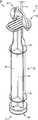
- FIG. 1is a perspective view of a syringe plunger having a pivoting or hinged pressure flange according to an example embodiment of the present invention, the flange being positioned in a flat or collapsed configuration.
- FIG. 2shows the plunger of FIG. 1 , showing the flange positioned in an extended or upright configuration and showing a hook portion being looped through a portion of the flange for hanging the plunger (and syringe).
- FIG. 3shows a detailed view of a portion of the plunger of FIG. 2 .
- FIG. 4shows a detailed bottom perspective view of a portion of the plunger of FIG. 3 .
- FIG. 5shows a cross-sectional view of a portion of the plunger of FIG. 1 taken along line 5 - 5 , showing interengagement of portions of the flange with an end plate of the plunger.
- FIG. 6shows a side view of the plunger of FIGS. 3-4 , showing the flange positioned in the extended or upright configuration.
- FIG. 7shows a side view of the plunger with the flange positioned in a substantially flat or collapsed configuration, showing a hinge thereof being at least partially flexed.
- FIG. 8shows a side view of the plunger of FIG. 1 , showing the flange being positioned in a substantially flat or collapsed configuration wherein the hinge connecting the flange to the plunger is substantially unflexed and planar.
- FIG. 9shows a front perspective view of a syringe plunger having a pivoting or hinged pressure flange according to another example embodiment of the present invention, the flange being positioned in an extended or upright configuration.
- FIG. 10shows a rear perspective view of the syringe plunger of FIG. 9 , the flange being in a flat or collapsed configuration.
- FIG. 11shows a rear perspective view of a portion of the syringe plunger of FIG. 9 .
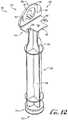
- FIG. 12shows a perspective view of a syringe plunger having a pivoting or hinged pressure flange according to another example embodiment of the present invention, the flange being positioned in an extended or upright configuration.
- FIG. 13shows a rear perspective view of the syringe plunger of FIG. 12 , and showing the flange being positioned in a flat or collapsed configuration.
- FIG. 14shows the syringe plunger of FIG. 13 , showing the flange being positioned in an extended or upright configuration.
- FIG. 15shows a syringe plunger having an opening or engagement portion according to another example embodiment of the present invention.
- FIG. 16shows a detailed perspective view of the plunger of FIG. 15 .
- FIG. 17shows a syringe comprising the plunger of FIG. 1 movably mounted therein, and showing the syringe and plunger being engaged with a syringe pump according to an example embodiment of the present invention.
- FIG. 18shows a syringe comprising the plunger of FIG. 2 , and showing the flange thereof in an extended or upright configuration whereby a hook or other support engages the flange to suspend the syringe for use as a gravity feed system.
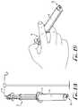
- FIG. 19shows a syringe comprising the plunger of FIG. 1 , and showing a user manually operating the plunger by depressing the pressure plate with the hinged flange in a flat or collapsed configuration.
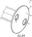
- FIG. 20shows a syringe plunger having a contact face according to another example embodiment of the present invention.
- FIGS. 1-8show a syringe plunger 10 according to an example embodiment of the present invention.
- the plunger 10is configured for sealingly engaging the interior containment cavity of a syringe barrel or body, for example, wherein advancement or retraction of the plunger 10 within the cavity of the syringe barrel varies the contained volume of the syringe to discharge or fill the syringe with fluid contents such as fluids for enteral delivery.
- the syringeis optionally a vented syringe, having one or more vents allowing fluid passage between the syringe barrel and plunger, such that the plunger is movable between a vented position and a sealed/vacuum position.
- the syringe plunger 10comprises a first or distal end 12 and a second or proximal end 14 .
- the distal end 12comprises a sealing head 16 for tightly engaging an inner wall of a cavity of a syringe body with a fluid tight seal
- the proximal end 14comprises a pressure plate, thumb pad or contact face 20 to engage a depressor of a syringe pump (or permit user manipulation by hand operation).
- a main body portion 22 of the plunger 10generally connects the first end 12 to the second end 14 .
- the main body portion 22generally comprises one or more planar ribs 24 connecting the sealing head 16 to the contact face 20 .
- the main body portion 22comprises generally uniform ribs 24 having a cruciform cross-section in the shape of a plus (+) sign.
- cross-sections of other desired shapes and configurationscan be chosen as desired.
- the contact face 20 of the syringe plunger 10comprises a fixed portion 30 and a hinged or flange portion 50 generally mounted to move relative to the fixed portion 30 .
- the ribs 24can comprise one or more cutouts, which reduce the overall diameter of the ribs to a size for engagement with the fixed portion 30 of the contact face 20 .
- one or more discs or supports 26can be formed with one or more of the ribs 24 along the length of the main body portion 22 for providing additional support.
- the flange portion 50 of the contact face 20 of the syringe plunger 10is generally hinged to pivot relative to two generally symmetrical wings or arms 32 extending from opposite sides of the fixed portion 30 .
- the contact face 20 of the plunger 10is generally disc-shaped or generally circular whereby the fixed portion 30 is generally T-shaped and the flange portion 50 is generally U-shaped, for example, wherein the ends of the U-shaped flange portion 50 are pivotally or hingedly mounted to upper horizontal ends 34 of the T-shaped fixed portion 30 (e.g., the arms 32 ), such that in a retracted or collapsed configuration (see FIG.
- a central member or portion 40 of the T-shaped fixed portion 30can be received in an 56 opening of the U-shaped flange portion 50 to form a generally flat and uniform contact face 20 adapted for manipulation by a user or a syringe pump.
- a living hinge 60is provided between the fixed and flange portions 30 , 50 of the syringe plunger 10 such that the two portions are generally integrally formed together with a thin web of flexible material extending therebetween, allowing for hinged movement of the flange portion 50 relative to the fixed portion 30 , for example, between a closed, flat, collapsed or retracted position (see FIG. 1 ), and an open, expanded, extended or upright configuration (see FIGS.
- the living hinge 60is generally integrally connected between the upper horizontal ends 34 of the fixed portion 30 (see FIG. 3 ) and hinge connection faces 62 defined at the ends of the arms 52 of the flange portion 50 (see FIG. 4 ).
- the living hinge 60can be provided on other portions of the fixed and flange portions 30 , 50 , for example, to permit movement of the flange portion 50 relative to the fixed portion 30 between the collapsed configuration (see FIGS. 5 and 8 ) and the upright configuration.
- the flange portion 50comprises two end extensions or arms 52 that are generally offset from one another and a middle section or central connection portion 54 connecting together top portions of the two arms 52 , for example, to form a generally upside-down U-shaped member.
- the contact face or pressure plate 20is generally circular in shape, and thus, the middle section 54 and outer portions of the arms 52 are generally arcuate or radiused to match the profile of the contact face. As depicted in FIGS.
- the flange portion 50comprises at least one engagement or coupling feature for providing coupling engagement with a portion of the fixed member, for example, when the flexible member is moved to the collapsed configuration such that upper surfaces 46 , 70 of the fixed and flange portions 30 , 50 are substantially planar relative to each other.
- a ridge, protrusion, clip or ledge 64is provided along interior portions of the arms 52 for providing removable engagement with portions of the fixed portion.
- opposite sides of the central member 40 of the fixed portion 30comprise channels 42 for receiving and providing coupling interengagement with the ledges 64 of the arms 52 of the flange portion 50 .
- the features of the upper surfaces of the fixed and flange portionsare matching such that in the retracted configuration the contact face is completed and can be used normally (e.g., for compressing in a pump or grasping for moving the plunger relative to the syringe barrel).
- the upper surfaces of the fixed and flange portions 30 , 50comprise gripping or surface features in the form of a linear array of ribs or channels.
- the fixed portion 30comprises one or more surface features 47 and the flange portion comprises surface features 72 .
- other surface featurescan be provided as desired.
- moving the flange portion to a retracted or closed positioncauses the flange portion 50 to become engaged with the fixed portion 30 such that the flange portion 50 is mounted at a position relative to the fixed portion to cause upward bulging or outwardly bowing of the living hinges 60 for example, such that the flange portion is generally positioned at least partially closer than the extension of the flange portion (see FIG. 7 ).
- a user or feed pumpmay apply a force to the contact face 20 to move the flange portion 50 outwardly relative to the fixed portion 30 .
- ends 36 of the arms 32 of the fixed portion 30 relative to ends of the arms 62 of the flange portion 50comprises a length X of between about 0.1 to about 1 millimeters, more preferably between about 0.2 to about 0.8 millimeters, for example about 0.6 millimeters according to example embodiments.
- a usercan move the flange portion from a closed position to an open position by pushing upwards on at least a portion of the flange portion while holding the fixed portion and/or the main body portion of the syringe plunger.
- the contact face 20comprises a thickness T of between about 1.50-2.50 millimeters, for example between about 2.00-2.25 millimeters according to an example embodiment of the present invention.
- other thicknesses Tcan be provided as desired.
- the flange portion 50is in the upright configuration with flange portion 50 generally extending at an angle ⁇ relative to the fixed portion 30 , for example, wherein a is generally between about 25-165 degrees, more particularly for example between about 45-135 degrees, for example about 90 degrees according to example embodiments.
- the plunger 10is formed by injection molding whereby the flange portion 50 is molded in the upright configuration with the angle ⁇ being about 90 degrees.
- the flange portion 50generally extends at an angle of about 90 degrees relative to an upper surface of the fixed portion.
- an IV hook or other hook or engagement membercan easily engage the flange portion by extending a portion thereof through an opening 56 formed between the arms 52 and the central connection portion 54 of the flange portion 50 , and the upper surface 46 of the fixed portion 30 (see FIG. 18 ).
- FIGS. 9-11show a plunger 100 according to another example embodiment of the present invention.
- the plunger 100is generally similar to the plunger 10 and comprises a first or distal end 112 and a second or proximal end 114 .
- the distal end 112comprises a sealing head 116 for tightly engaging an inner wall of a cavity of a syringe body with a fluid tight seal
- the proximal end 114comprises a pressure plate, thumb pad or contact face 120 to engage a depressor of a syringe pump (or permit user manipulation by hand operation).
- a main body portion 122 of the plunger 100generally connects the first end 112 to the second end 114 .
- the main body portion 122generally comprises one or more planar ribs 124 connecting the sealing head 116 to the contact face 120 .
- the contact face 120 at the second end 114comprises a fixed portion 130 and a hinged hanging flange portion 150 that is movable relative to the fixed portion 130 .
- the flange portion 150is connected to the fixed portion 130 by a plurality resiliently flexible living hinges 164 , for example, about 9 separate hinges.
- more or less hingescan be provided as desired.
- the fixed portion 130generally comprises a portion of a complete disc-shaped contact face
- the flange portion 150comprises the other portion of the complete disc-shaped contact face
- the flexible living hinges 164generally extend between an end face 134 of the fixed portion 130 and an end face 166 of the flange portion 150 , for example, such that the flange portion 150 is movable between the collapsed configuration ( FIG. 10 ) and the upright configuration ( FIGS. 9 and 11 ).
- the fixed portion 130comprises at least one interengagement feature 136 for coupling the flange portion 150 in the collapsed configuration, for example, such that the pressure plate 120 can be compatible for engagement with a syringe pump or for being pressed by a user's thumb (see FIGS. 17-19 ).
- the interengagement feature 136comprises a platform 140 having a pair of engagement fingers 142 extending outwardly from the end face 134 of the fixed portion 130 (and the fingers 142 being generally laterally offset from the platform 140 ) for being received within a pair of spaced-apart channels or receivers 162 formed in the flange portion 150 .
- the receivers 162comprise end engagement surfaces 163 for providing engagement with the fingers 142 .
- the fingers 142comprise end surfaces 143 for engaging the end engagement surfaces 163 of the receivers 162 when the flange portion 150 is in the collapsed configuration.
- a lower surface 156 of the flange portion 150generally contacts the platform 140 .
- the upper surfaces 144 , 152 of the fixed and flange portions 130 , 150comprise surface features 146 , 154 in the form of protruding and spaced-apart ribs.
- the fingers 142 extending from the fixed portion 130are generally extensions of two of the surface features 146 . According to example embodiments, the fingers 142 generally extend a length such that there is at least some interference of the end surfaces 143 and the end engagement surfaces 163 .
- other engagement or coupling featurescan be provided for coupling the flange portion 130 in the collapsed configuration.
- flange portion 130can comprise one or more holes, slots or other openings 160 formed therein for receiving an IV hook or other engagement member for suspending the plunger and an attached syringe.
- the flange portion 150generally comprises a circular opening formed through the flange portion 150 , for example, about at a midpoint defined therebetween.
- the opening 160can be other shapes including polygonal, oval, or other shapes as desired.
- FIGS. 12-14show a syringe plunger 200 according to another example embodiment of the present invention.
- the contact face 220is generally disc-shaped and comprises a fixed portion 230 and a flange portion 250 , and wherein the flange portion 250 is generally movably mounted to pivot relative to a portion of the fixed portion 230 about a linear pivot edge 232 .
- a single living hinge 264pivotally joins the flange portion 250 to the fixed portion 230 across the width of the contact face 220 of the syringe plunger.
- a pair of generally elongate and radiused protrusions 262 of the flange portionare configured for coupling interengagement with engagement receivers 240 of a platform 236 of the fixed portion 130 .
- the receivers 240 and the protrusions 262are generally complementary in shape, for example, to provide for fitting interengagement therebetween.
- the coupling engagement of the receivers 240 and protrusions 262is such that at least some interference if provided therebetween, for example to ensure some amount of frictional engagement therebetween generally keeps the flange portion 150 in the collapsed configuration.
- the useruses a finger or other tool to lift the flange portion relative to the fixed portion.
- an end portion 238 of the platform 236comprises a larger radiused cutout (defined between the two engagement receivers 240 ) such that a portion of the flange portion 250 overhangs the platform 136 and beyond the end portion 238 .
- a finger, tool or other devicecan engage only a portion of the flange portion 250 to move the flange portion 250 from the collapsed configuration to the upright configuration.
- an openingcan be formed through the flange portion 250 for receiving an IV hook or other hanging support.
- the top surfaces of the fixed portion and the flange portioncomprise an array of protruding ribs 244 , 254 .
- FIGS. 15-16show a plunger 300 according to another example embodiment of the present invention.
- the plunger 300is generally similar to the plungers 10 , 100 , 200 as described above, for example, which comprises a first or distal end 312 and a second or proximal end 314 .
- the distal end 312comprises a sealing head 316 for tightly engaging an inner wall of a cavity of a syringe body with a fluid tight seal
- the proximal end 314comprises a contact face 320 to engage a depressor of a syringe pump or permit user manipulation by hand operation.
- a main body portion 322 of the plunger 300generally connects the first end 312 to the second end 314 .
- the main body portion 322generally comprises one or more planar ribs 324 connecting the sealing head 316 to the contact face 320 .
- an engagement feature 330comprising a U-shaped connector or spaced-apart arms 332 connect the main body portion 322 to the contact face 320 .
- at least one pass-through or opening 334is formed within the engagement feature 330 such that an IV hook or other hanging support can engage therewith for hanging the plunger (and syringe attached thereto).
- the contact face 320is generally circular in shape and comprises a generally planar upper surface 340 having a plurality of spaced-apart ribs 342 protruding from the upper surface 340 thereof.
- the hinged portion of the contact flange of the syringe plungeris positioned in its flat or retracted position for use with a syringe S when using a syringe pump SP or for manual actuation of the syringe (see FIGS. 17 and 19 ).
- the syringe Scomprises a female connector FC (see FIGS. 18-19 ) in the form of an ENFit compatible connector or coupling, for example, which can be connected with another ENFit compatible coupling (which can be connected to a feeding tube FT).
- one or more syringe pump clamps Cpreferably engage the contact flange of the plunger to retain the contact flange up against the driving arm of the pump.
- the thickness T of the contact flangeis preferably between about 2-2.25 millimeters, for example, which provides a sufficient thickness for accommodating engagement with the syringe pump clamps C.
- the hinged portion of the contact flange of the syringe plungeris positioned in its upright or extended position for hanging a syringe S in gravity-feed applications, with an IV hook or other hanging support H extending through the opening in the hinged portion of the contact flange to hang the syringe (see FIG. 18 ).
- the syringe Scomprises one or more vents V, for example, to utilize the syringe assembly in a gravity-feed system.
- the vented syringe and plunger of the present inventioncan be used for manual manipulation or mounted for use with a syringe pump SP.
- the packaged plunger(e.g., before being opened by an end user) is generally configured such that the hinged portion is in its flat or retracted position.
- the home position of the hinged flangeis generally in the flat, retracted position, for example, which can be manipulated with one or more fingers or thumb, and for compatible use with a metering pump.
- one or more of the molded plungerscan be directed to an assembly line or feeding machine whereby one or more machines and/or operators move the flange portion from the upright configuration to the collapsed configuration, for example, such that the plunger, when assembled individually or with the syringe, is packaged with the flange in the collapsed configuration.
- the plunger with the flange in the upright configurationcan be assembled with the syringe and then the assembly can be moved through an automated process whereby a portion of the syringe is captured by a machine or fixture which in turn performs one or more steps to move the flange portion of the contact face from the upright configuration to the collapsed configuration.
- an individualcan grab the assembled syringe and plunger and manually move the flange portion from the upright configuration to the collapsed configuration.
- FIG. 20shows a plunger 400 according to another example embodiment of the present invention.
- the plunger 400comprises a contact face 420 comprising an upper surface 422 and optionally having a plurality of raised projections or other surface features, for example, as described above with respect to other embodiments of the invention.
- the contact face 420is generally a one piece circular disc having one or more openings 430 extending through the entirety of the contact face 420 , for example such that an IV hook or other hanging support H can extend through at least one of the openings 430 to provide for suspending or hanging of the syringe plunger 400 (and syringe barrel S connected with the plunger 400 ).
- the openingsare generally circular in shape and sized for compatibility with the support H.
- openings of other shapes and sizescan be provided as desired.
- one of the openingscan be shaped and sized for compatibility with a first support type, hanger or feature, and the other openings can be sized and shaped for compatibility with another support type, hanger or feature, for example, wherein multiple supportive features can be used to hang the syringe therefrom.
- the one or more openingscan be sized and shaped for compatibility with a range of supports is various sizes and shapes.
Landscapes
- Health & Medical Sciences (AREA)
- Life Sciences & Earth Sciences (AREA)
- Veterinary Medicine (AREA)
- Public Health (AREA)
- General Health & Medical Sciences (AREA)
- Animal Behavior & Ethology (AREA)
- Heart & Thoracic Surgery (AREA)
- Anesthesiology (AREA)
- Hematology (AREA)
- Biomedical Technology (AREA)
- Engineering & Computer Science (AREA)
- Vascular Medicine (AREA)
- Pulmonology (AREA)
- Infusion, Injection, And Reservoir Apparatuses (AREA)
Abstract
Description
Claims (23)
Priority Applications (2)
| Application Number | Priority Date | Filing Date | Title |
|---|---|---|---|
| US15/439,711US10722432B2 (en) | 2016-02-25 | 2017-02-22 | Syringe plunger with hinged flange |
| US16/907,777US11925791B2 (en) | 2016-02-25 | 2020-06-22 | Syringe plunger with hinged flange |
Applications Claiming Priority (2)
| Application Number | Priority Date | Filing Date | Title |
|---|---|---|---|
| US201662299604P | 2016-02-25 | 2016-02-25 | |
| US15/439,711US10722432B2 (en) | 2016-02-25 | 2017-02-22 | Syringe plunger with hinged flange |
Related Child Applications (1)
| Application Number | Title | Priority Date | Filing Date |
|---|---|---|---|
| US16/907,777DivisionUS11925791B2 (en) | 2016-02-25 | 2020-06-22 | Syringe plunger with hinged flange |
Publications (2)
| Publication Number | Publication Date |
|---|---|
| US20170246087A1 US20170246087A1 (en) | 2017-08-31 |
| US10722432B2true US10722432B2 (en) | 2020-07-28 |
Family
ID=58231741
Family Applications (2)
| Application Number | Title | Priority Date | Filing Date |
|---|---|---|---|
| US15/439,711ActiveUS10722432B2 (en) | 2016-02-25 | 2017-02-22 | Syringe plunger with hinged flange |
| US16/907,777Active2037-09-01US11925791B2 (en) | 2016-02-25 | 2020-06-22 | Syringe plunger with hinged flange |
Family Applications After (1)
| Application Number | Title | Priority Date | Filing Date |
|---|---|---|---|
| US16/907,777Active2037-09-01US11925791B2 (en) | 2016-02-25 | 2020-06-22 | Syringe plunger with hinged flange |
Country Status (4)
| Country | Link |
|---|---|
| US (2) | US10722432B2 (en) |
| EP (1) | EP3419696B1 (en) |
| CA (1) | CA3015874A1 (en) |
| WO (1) | WO2017147192A1 (en) |
Cited By (3)
| Publication number | Priority date | Publication date | Assignee | Title |
|---|---|---|---|---|
| US20210100962A1 (en)* | 2019-02-27 | 2021-04-08 | Born Life Hacks, LLC | Syringe and Plunger Clip for Bottles |
| USD956205S1 (en)* | 2020-11-24 | 2022-06-28 | Takeda Pharmaceutical Company Limited | Pusher foot for a fluid delivery device |
| USD1056204S1 (en)* | 2022-05-25 | 2024-12-31 | Dna Genotek Inc. | Floater for a liquid collection device |
Families Citing this family (4)
| Publication number | Priority date | Publication date | Assignee | Title |
|---|---|---|---|---|
| US11173248B2 (en)* | 2018-04-23 | 2021-11-16 | Kellida Inc. | Method and system for operating a plunger |
| US11998723B2 (en) | 2019-02-26 | 2024-06-04 | Becton, Dickinson & Company | Vented syringe |
| USD911519S1 (en)* | 2019-05-29 | 2021-02-23 | Radiometer Medical Aps | Syringe plunger |
| WO2021062417A1 (en)* | 2019-09-29 | 2021-04-01 | F3 Biodesigns, Llc | Enteral feeding device and method of using the same |
Citations (99)
| Publication number | Priority date | Publication date | Assignee | Title |
|---|---|---|---|---|
| FR1126718A (en) | 1955-06-25 | 1956-11-29 | Maintained Orientation Syringe | |
| US3026872A (en)* | 1952-05-17 | 1962-03-27 | American Cyanamid Co | Hypodermic syringe |
| US3113873A (en) | 1961-09-01 | 1963-12-10 | Anaconda Aluminum Co | Food package |
| US3581928A (en)* | 1968-10-14 | 1971-06-01 | American Hospital Supply Corp | Hanger construction for medical liquid container |
| DE2108381A1 (en) | 1971-01-29 | 1972-08-24 | Doller, Arthur, 7800 Freiburg | Injection or suction ampoule |
| US3731684A (en) | 1971-04-08 | 1973-05-08 | Cenco Medical Health Supply Co | Closed irrigation and urinary drainage system apparatus |
| US3880311A (en) | 1974-02-26 | 1975-04-29 | American Hospital Supply Corp | Collapsible medical liquid bottle with calibration and label orienting hanger structure |
| US3885562A (en) | 1973-11-16 | 1975-05-27 | John C Lampkin | Syringe with writing surface |
| US3900184A (en) | 1973-12-13 | 1975-08-19 | Burron Medical Prod Inc | Roller clamp for tubing |
| US3910273A (en)* | 1973-03-08 | 1975-10-07 | Sven Arlers | Aspirating hypodermic syringe |
| US4153056A (en)* | 1977-06-16 | 1979-05-08 | Jules Silver | Syringe with removable length adjusting member |
| US4356824A (en) | 1980-07-30 | 1982-11-02 | Vazquez Richard M | Multiple lumen gastrostomy tube |
| USD267536S (en) | 1980-11-10 | 1983-01-11 | Impact Products, Inc. | Combined scoop, funnel, and pourer |
| US4392851A (en) | 1981-11-23 | 1983-07-12 | Abbott Laboratories | In-line transfer unit |
| US4413741A (en)* | 1981-12-16 | 1983-11-08 | Baxter Travenol Laboratories, Inc. | Hanger assembly for bottles |
| US4460143A (en)* | 1981-04-23 | 1984-07-17 | Fujisawa Pharmaceutical Co., Ltd. | Vial suspender |
| USD282807S (en) | 1984-03-02 | 1986-03-04 | Hasse Patricia W | Guard funnel |
| USD282962S (en) | 1983-02-14 | 1986-03-11 | Gerber Albert J | Plastic tubing connector |
| USD307795S (en) | 1987-06-16 | 1990-05-08 | Frantz Medical Development Ltd. | Combined disposable medical pump cassette and connectors for enteral fluid delivery pump systems |
| US4994048A (en) | 1988-09-19 | 1991-02-19 | Becton, Dickinson And Company | Apparatus and method for connecting a passageway and openings with a connector |
| EP0481250A1 (en) | 1990-10-16 | 1992-04-22 | von Schuckmann, Alfred | Cartridge for fitting in a dispenser |
| US5137527A (en) | 1990-09-20 | 1992-08-11 | Clintec Nutrition Co. | Enteral-specific spike/bag port system |
| US5137511A (en)* | 1987-07-08 | 1992-08-11 | Duoject Medical Systems Inc. | Syringe |
| USD330862S (en) | 1990-07-20 | 1992-11-10 | Charles Shibley | Combined formula mixer and container |
| US5202533A (en) | 1992-01-28 | 1993-04-13 | Vandersteen Douglas G A | Drug injection apparatus for an animal |
| US5279566A (en) | 1992-12-23 | 1994-01-18 | Ronald S. Kline | Protective assembly for hypodermic syringes |
| US5460603A (en) | 1993-04-08 | 1995-10-24 | Massachusetts Institute Of Technology | Method and apparatus for preventing back flow in gastroenterological feeding system |
| US5549550A (en) | 1995-01-13 | 1996-08-27 | Abbott Laboratories | Method of adding marker dye to nutritional product during enteral tube feeding |
| US5611787A (en) | 1994-10-13 | 1997-03-18 | Methodist Hospital Of Indiana, Inc. | Method and device for gastric line insertion |
| DE29617949U1 (en) | 1996-10-01 | 1997-04-30 | Schulz, Klaus, Dr.med., 50259 Pulheim | Syringe with a closable venting channel or venting gap |
| US5746733A (en) | 1994-05-19 | 1998-05-05 | Becton, Dickinson And Company | Syringe filling and delivery device |
| US5755689A (en) | 1995-01-13 | 1998-05-26 | Abbott Laboratories | Apparatus for adding marker dye to nutritional product during enteral tube feeding |
| US5779668A (en) | 1995-03-29 | 1998-07-14 | Abbott Laboratories | Syringe barrel for lyophilization, reconstitution and administration |
| US5832971A (en) | 1994-05-19 | 1998-11-10 | Becton, Dickinson And Company | Syringe filling and delivery device |
| US5843042A (en) | 1996-11-06 | 1998-12-01 | Ren; Liang Chen | Oral medicine dispensing device having a metered syringe component and reservoir |
| US6019747A (en) | 1997-10-21 | 2000-02-01 | I-Flow Corporation | Spring-actuated infusion syringe |
| US6029946A (en) | 1997-09-15 | 2000-02-29 | Tiva Medical Inc. | Needleless valve |
| US6036669A (en) | 1995-01-13 | 2000-03-14 | Abbott Laboratories | Apparatus for altering composition of nutritional product during enteral tube feeding |
| US6065649A (en)* | 1997-10-23 | 2000-05-23 | Scoggins; Lester E. | Dispensing container with top and bottom access ports and a dispensing manifold therefore |
| EP1110568A2 (en) | 1999-12-21 | 2001-06-27 | CANE' S.r.l. | Syringe for infusing drugs |
| US6277092B1 (en) | 1995-01-13 | 2001-08-21 | Abbott Laboratories | Apparatus for altering composition of nutritional product during enteral tube feeding |
| USD447797S1 (en) | 1998-10-13 | 2001-09-11 | Becton, Dickinson And Company | Syringe |
| USD461243S1 (en) | 2000-12-04 | 2002-08-06 | Bracco Diagnostics Inc. | Ellipsoidal syringe barrel |
| US6482170B1 (en) | 2000-09-18 | 2002-11-19 | Corpak, Inc. | Apparatus and method for relieving gastric pressure during enteral feeding |
| US20030014005A1 (en)* | 2000-03-17 | 2003-01-16 | Atsushi Chiba | Syringe |
| US20040054350A1 (en) | 2002-09-17 | 2004-03-18 | Shaughnessy Michael C. | Enteral feeding unit having a reflux device and reflux method |
| US6752790B2 (en) | 2002-02-27 | 2004-06-22 | Karla Coombs | Dosage vessel for use with an indwelling feeding tube |
| US6766917B1 (en)* | 2002-09-11 | 2004-07-27 | Blewitt, Iii John J. | Closure with hinged hook |
| US6962563B2 (en) | 2001-09-19 | 2005-11-08 | Olympus Corporation | Surgical apparatus |
| US7118554B2 (en) | 1999-05-03 | 2006-10-10 | Science & Technology Corp @ Unm | Reciprocating syringes |
| US20060264824A1 (en) | 2005-05-20 | 2006-11-23 | Swisher Kyle Y Iii | Disposable safety medical syringe assembly and method of manufacture |
| US20070060898A1 (en) | 2005-09-07 | 2007-03-15 | Shaughnessy Michael C | Enteral medical treatment assembly having a safeguard against erroneous connection with an intravascular treatment system |
| US20070123822A1 (en) | 2005-11-25 | 2007-05-31 | Biotop Holding Co., Ltd. | Safety syringe for taking blood |
| WO2007095541A2 (en) | 2006-02-13 | 2007-08-23 | Gerald Moss | Plural lumen gastrostomy tube insert for placement into the duodenum and method of monitoring and managing feeding |
| USD552773S1 (en) | 2006-12-20 | 2007-10-09 | Yafa Pen Company | Syringe flashlight |
| US20070265579A1 (en) | 2006-05-10 | 2007-11-15 | Gennady Kleyman | Dental syringe |
| US20080097348A1 (en) | 2004-05-11 | 2008-04-24 | Martin Itrich | Enteral Feeding Probe and Tube System for Enteral Feeding and Gastric Decompression or Drainage |
| US20080183153A1 (en) | 2007-01-31 | 2008-07-31 | Benlan, Inc. | Enteral Feeding Tube Connector |
| USD578210S1 (en) | 2006-03-14 | 2008-10-07 | Hisamitsu Pharmaceutical Co., Inc. | Injector |
| EP1980282A1 (en) | 2007-04-10 | 2008-10-15 | F.Hoffmann-La Roche Ag | Medicine reservoir and device for automatic dispensing of a liquid medicine |
| US20080255501A1 (en) | 2007-04-10 | 2008-10-16 | Michael Hogendijk | Percutaneous delivery and retrieval systems for shape-changing orthopedic joint devices |
| US20080255523A1 (en) | 2007-04-13 | 2008-10-16 | Yair Grinberg | Hypodermic Syringe With Vial Attachment |
| US7560686B2 (en) | 2006-12-11 | 2009-07-14 | Tyco Healthcare Group Lp | Pump set and pump with electromagnetic radiation operated interlock |
| US20090287161A1 (en) | 2008-05-15 | 2009-11-19 | Allergan, Inc | Metered, multiple dose/aliquot syringe |
| WO2009141510A1 (en) | 2008-05-20 | 2009-11-26 | Sannier Gerard | Gel dispenser |
| USD618347S1 (en) | 2009-06-04 | 2010-06-22 | Cynthia Bradshaw | Applicator suppository injector |
| US20100249719A1 (en) | 2007-10-01 | 2010-09-30 | Covidien Ag | Methods for Manually Injecting/Aspirating Fluids Through Small Diameter Catheters and Needles and Manual Injection/Aspiration Systems Including Small Diameter Catheters and Needles |
| US7842217B2 (en) | 2007-03-28 | 2010-11-30 | Benlan, Inc. | Enteral-only syringe and method of manufacturing same |
| US7846131B2 (en) | 2005-09-30 | 2010-12-07 | Covidien Ag | Administration feeding set and flow control apparatus with secure loading features |
| USD632144S1 (en) | 2009-11-19 | 2011-02-08 | Weisenbach Specialty Printing, Inc. | Spout |
| WO2011026156A1 (en) | 2009-08-24 | 2011-03-03 | Clinton Frederick Shahim | Closed wound drainage system |
| USD635249S1 (en) | 2009-11-10 | 2011-03-29 | Bruce Becker | Syringe |
| US7921847B2 (en) | 2005-07-25 | 2011-04-12 | Intubix, Llc | Device and method for placing within a patient an enteral tube after endotracheal intubation |
| US7955315B2 (en) | 2006-07-24 | 2011-06-07 | Ethicon, Inc. | Articulating laparoscopic device and method for delivery of medical fluid |
| US7980131B2 (en) | 2008-01-07 | 2011-07-19 | Jody Barton | Bottomless measuring cup |
| US20110184383A1 (en)* | 2008-10-06 | 2011-07-28 | Terumo Kabushiki Kaisha | Syringe pump |
| US20110192489A1 (en) | 2008-08-02 | 2011-08-11 | Walter Pobitschka | Method and device for transferring a substance between closed systems |
| USD646531S1 (en) | 2010-09-25 | 2011-10-11 | Murphy Trisha A | Funnel measuring cup |
| US20110270227A1 (en) | 2010-04-30 | 2011-11-03 | Baxa Corporation | Method and apparatus for the enteral dispensation of liquid medications |
| USD654585S1 (en) | 2010-12-02 | 2012-02-21 | Neomed, Inc. | Enteral syringe |
| USD654584S1 (en) | 2010-09-14 | 2012-02-21 | Neomed, Inc. | Enteral syringe |
| WO2012037082A1 (en) | 2010-09-14 | 2012-03-22 | Neomed, Inc. | Enteral syringe |
| US8162916B2 (en) | 2008-02-08 | 2012-04-24 | Codan Us Corporation | Enteral feeding safety reservoir and system |
| US20120150111A1 (en) | 2010-12-14 | 2012-06-14 | Hershey Adrienne A | Passive Enteral Venting System |
| US8231597B2 (en) | 2008-02-08 | 2012-07-31 | Codan Us Corporation | Enteral feeding safety reservoir and system |
| US8366697B2 (en) | 2008-02-08 | 2013-02-05 | Codan Us Corporation | Enteral feeding safety reservoir and system |
| US20130082057A1 (en) | 2011-09-30 | 2013-04-04 | Becton Dickinson France, S.A.S. | Syringe Assembly Having a Telescoping Plunger Rod |
| US20130131606A1 (en)* | 2011-11-21 | 2013-05-23 | University Of Louisville Research Foundation, Inc. | Ergonomic syringe and adaptor |
| US8540683B2 (en) | 2006-10-09 | 2013-09-24 | Acist Medical Systems, Inc. | Syringe device and injector system including a vent for relieving a vacuum within a syringe |
| US8550418B2 (en) | 2008-11-10 | 2013-10-08 | Curlin Medical, Inc. | Syringe hanger |
| US20140039462A1 (en) | 2012-08-06 | 2014-02-06 | Neomed, Inc. | System and method for metered enteral feeding |
| US8715244B2 (en) | 2009-07-07 | 2014-05-06 | C. R. Bard, Inc. | Extensible internal bolster for a medical device |
| US8777900B2 (en) | 2010-12-14 | 2014-07-15 | Kimberly-Clark Worldwide, Inc. | Ambulatory enteral feeding system |
| US20140213985A1 (en) | 2011-09-08 | 2014-07-31 | Sanofi SAentis Deutschland GmbH | Securing Means for a Drug Delivery Device |
| US9301587B2 (en) | 2013-01-14 | 2016-04-05 | Stephen D'Amico | Hair color (or dye) storage, dispensing and measurement (or measuring) system |
| US9333288B2 (en) | 2011-09-30 | 2016-05-10 | Becton Dickinson France, S.A.S. | Attachable plunger rod and associated packaging |
| US9433729B2 (en) | 2010-09-14 | 2016-09-06 | Neomed, Inc. | Enteral syringe |
| US9433562B2 (en) | 2010-07-27 | 2016-09-06 | Neomed, Inc. | System for aseptic collection and enteral delivery |
| US20160287798A1 (en)* | 2013-11-26 | 2016-10-06 | Carebay Europe Ltd | Housing Blank and Activation Member Blank for a Medicament Delivery Device, a Kit Comprising Such Blanks, and a Medicament Delivery Device |
Family Cites Families (15)
| Publication number | Priority date | Publication date | Assignee | Title |
|---|---|---|---|---|
| US2051940A (en)* | 1934-08-15 | 1936-08-25 | Chichester-Mi Herbert G Wright | Bucket and pail |
| US3119541A (en)* | 1961-12-28 | 1964-01-28 | Celluplastics Inc | Hanging cap and container combination |
| US3341047A (en)* | 1966-05-10 | 1967-09-12 | Abbott Lab | Container and bail construction |
| USD288667S (en)* | 1984-07-11 | 1987-03-10 | Miner Container Printing, Inc. | Container closure |
| USD332379S (en)* | 1991-12-09 | 1993-01-12 | Rubbermaid Incorporated | Lid for storage jar with handle |
| US5232112A (en)* | 1992-04-13 | 1993-08-03 | Ruco Products, Inc. | Molded lid for receiving handle |
| US5244113A (en)* | 1992-08-24 | 1993-09-14 | Northwestern Bottle Company | Container lid assembly |
| USD474115S1 (en)* | 2002-03-20 | 2003-05-06 | Masterchem Industries, Inc. | Container |
| USD511457S1 (en)* | 2004-01-29 | 2005-11-15 | Drug Plastics & Glass Company, Inc. | Container closure with handle |
| USD703997S1 (en)* | 2012-09-13 | 2014-05-06 | La Termoplastic F.B.M. S.R.L. | Knob with a movable handle for use on cooking utensils and apparatus |
| USD720218S1 (en)* | 2013-10-15 | 2014-12-30 | Confluence Beverages, LLC | Bottle cap |
| JP6427919B2 (en)* | 2014-03-31 | 2018-11-28 | 株式会社ジェイ・エム・エス | Syringe |
| USD759500S1 (en)* | 2014-04-28 | 2016-06-21 | Jab Distributors, Llc. | Jar package |
| USD742064S1 (en)* | 2015-06-23 | 2015-10-27 | The Hand Media, Inc. | Personal vaporizer compartment cover |
| USD853182S1 (en)* | 2018-01-12 | 2019-07-09 | Klean Kanteen, Inc. | Beverage container cap |
- 2017
- 2017-02-22WOPCT/US2017/018957patent/WO2017147192A1/ennot_activeCeased
- 2017-02-22EPEP17709267.3Apatent/EP3419696B1/enactiveActive
- 2017-02-22USUS15/439,711patent/US10722432B2/enactiveActive
- 2017-02-22CACA3015874Apatent/CA3015874A1/enactivePending
- 2020
- 2020-06-22USUS16/907,777patent/US11925791B2/enactiveActive
Patent Citations (107)
| Publication number | Priority date | Publication date | Assignee | Title |
|---|---|---|---|---|
| US3026872A (en)* | 1952-05-17 | 1962-03-27 | American Cyanamid Co | Hypodermic syringe |
| FR1126718A (en) | 1955-06-25 | 1956-11-29 | Maintained Orientation Syringe | |
| US3113873A (en) | 1961-09-01 | 1963-12-10 | Anaconda Aluminum Co | Food package |
| US3581928A (en)* | 1968-10-14 | 1971-06-01 | American Hospital Supply Corp | Hanger construction for medical liquid container |
| DE2108381A1 (en) | 1971-01-29 | 1972-08-24 | Doller, Arthur, 7800 Freiburg | Injection or suction ampoule |
| US3731684A (en) | 1971-04-08 | 1973-05-08 | Cenco Medical Health Supply Co | Closed irrigation and urinary drainage system apparatus |
| US3910273A (en)* | 1973-03-08 | 1975-10-07 | Sven Arlers | Aspirating hypodermic syringe |
| US3885562A (en) | 1973-11-16 | 1975-05-27 | John C Lampkin | Syringe with writing surface |
| US3900184A (en) | 1973-12-13 | 1975-08-19 | Burron Medical Prod Inc | Roller clamp for tubing |
| US3880311A (en) | 1974-02-26 | 1975-04-29 | American Hospital Supply Corp | Collapsible medical liquid bottle with calibration and label orienting hanger structure |
| US4153056A (en)* | 1977-06-16 | 1979-05-08 | Jules Silver | Syringe with removable length adjusting member |
| US4356824A (en) | 1980-07-30 | 1982-11-02 | Vazquez Richard M | Multiple lumen gastrostomy tube |
| USD267536S (en) | 1980-11-10 | 1983-01-11 | Impact Products, Inc. | Combined scoop, funnel, and pourer |
| US4460143A (en)* | 1981-04-23 | 1984-07-17 | Fujisawa Pharmaceutical Co., Ltd. | Vial suspender |
| US4392851A (en) | 1981-11-23 | 1983-07-12 | Abbott Laboratories | In-line transfer unit |
| US4413741A (en)* | 1981-12-16 | 1983-11-08 | Baxter Travenol Laboratories, Inc. | Hanger assembly for bottles |
| USD282962S (en) | 1983-02-14 | 1986-03-11 | Gerber Albert J | Plastic tubing connector |
| USD282807S (en) | 1984-03-02 | 1986-03-04 | Hasse Patricia W | Guard funnel |
| USD307795S (en) | 1987-06-16 | 1990-05-08 | Frantz Medical Development Ltd. | Combined disposable medical pump cassette and connectors for enteral fluid delivery pump systems |
| US5137511A (en)* | 1987-07-08 | 1992-08-11 | Duoject Medical Systems Inc. | Syringe |
| US4994048A (en) | 1988-09-19 | 1991-02-19 | Becton, Dickinson And Company | Apparatus and method for connecting a passageway and openings with a connector |
| USD330862S (en) | 1990-07-20 | 1992-11-10 | Charles Shibley | Combined formula mixer and container |
| US5137527A (en) | 1990-09-20 | 1992-08-11 | Clintec Nutrition Co. | Enteral-specific spike/bag port system |
| EP0481250A1 (en) | 1990-10-16 | 1992-04-22 | von Schuckmann, Alfred | Cartridge for fitting in a dispenser |
| US5202533A (en) | 1992-01-28 | 1993-04-13 | Vandersteen Douglas G A | Drug injection apparatus for an animal |
| US5279566A (en) | 1992-12-23 | 1994-01-18 | Ronald S. Kline | Protective assembly for hypodermic syringes |
| US5460603A (en) | 1993-04-08 | 1995-10-24 | Massachusetts Institute Of Technology | Method and apparatus for preventing back flow in gastroenterological feeding system |
| US5746733A (en) | 1994-05-19 | 1998-05-05 | Becton, Dickinson And Company | Syringe filling and delivery device |
| US5832971A (en) | 1994-05-19 | 1998-11-10 | Becton, Dickinson And Company | Syringe filling and delivery device |
| US5611787A (en) | 1994-10-13 | 1997-03-18 | Methodist Hospital Of Indiana, Inc. | Method and device for gastric line insertion |
| US5746715A (en) | 1995-01-13 | 1998-05-05 | Abbott Laboratories | Method of adding marker dye to nutritional product during enternal tube feeding |
| US5755689A (en) | 1995-01-13 | 1998-05-26 | Abbott Laboratories | Apparatus for adding marker dye to nutritional product during enteral tube feeding |
| US6036669A (en) | 1995-01-13 | 2000-03-14 | Abbott Laboratories | Apparatus for altering composition of nutritional product during enteral tube feeding |
| US6277092B1 (en) | 1995-01-13 | 2001-08-21 | Abbott Laboratories | Apparatus for altering composition of nutritional product during enteral tube feeding |
| US5549550A (en) | 1995-01-13 | 1996-08-27 | Abbott Laboratories | Method of adding marker dye to nutritional product during enteral tube feeding |
| US5779668A (en) | 1995-03-29 | 1998-07-14 | Abbott Laboratories | Syringe barrel for lyophilization, reconstitution and administration |
| DE29617949U1 (en) | 1996-10-01 | 1997-04-30 | Schulz, Klaus, Dr.med., 50259 Pulheim | Syringe with a closable venting channel or venting gap |
| US5843042A (en) | 1996-11-06 | 1998-12-01 | Ren; Liang Chen | Oral medicine dispensing device having a metered syringe component and reservoir |
| US6029946A (en) | 1997-09-15 | 2000-02-29 | Tiva Medical Inc. | Needleless valve |
| US6290206B1 (en) | 1997-09-15 | 2001-09-18 | Alaris Medical Systems, Inc. | Needleless valve |
| US6541802B2 (en) | 1997-09-15 | 2003-04-01 | Alaris Medical Systems, Inc. | Needleless valve |
| US6019747A (en) | 1997-10-21 | 2000-02-01 | I-Flow Corporation | Spring-actuated infusion syringe |
| US6065649A (en)* | 1997-10-23 | 2000-05-23 | Scoggins; Lester E. | Dispensing container with top and bottom access ports and a dispensing manifold therefore |
| USD447797S1 (en) | 1998-10-13 | 2001-09-11 | Becton, Dickinson And Company | Syringe |
| US7118554B2 (en) | 1999-05-03 | 2006-10-10 | Science & Technology Corp @ Unm | Reciprocating syringes |
| EP1110568A2 (en) | 1999-12-21 | 2001-06-27 | CANE' S.r.l. | Syringe for infusing drugs |
| US20030014005A1 (en)* | 2000-03-17 | 2003-01-16 | Atsushi Chiba | Syringe |
| US6482170B1 (en) | 2000-09-18 | 2002-11-19 | Corpak, Inc. | Apparatus and method for relieving gastric pressure during enteral feeding |
| USD461243S1 (en) | 2000-12-04 | 2002-08-06 | Bracco Diagnostics Inc. | Ellipsoidal syringe barrel |
| US6962563B2 (en) | 2001-09-19 | 2005-11-08 | Olympus Corporation | Surgical apparatus |
| US6752790B2 (en) | 2002-02-27 | 2004-06-22 | Karla Coombs | Dosage vessel for use with an indwelling feeding tube |
| US6766917B1 (en)* | 2002-09-11 | 2004-07-27 | Blewitt, Iii John J. | Closure with hinged hook |
| US20040054350A1 (en) | 2002-09-17 | 2004-03-18 | Shaughnessy Michael C. | Enteral feeding unit having a reflux device and reflux method |
| US20080097348A1 (en) | 2004-05-11 | 2008-04-24 | Martin Itrich | Enteral Feeding Probe and Tube System for Enteral Feeding and Gastric Decompression or Drainage |
| US20060264824A1 (en) | 2005-05-20 | 2006-11-23 | Swisher Kyle Y Iii | Disposable safety medical syringe assembly and method of manufacture |
| US7921847B2 (en) | 2005-07-25 | 2011-04-12 | Intubix, Llc | Device and method for placing within a patient an enteral tube after endotracheal intubation |
| US20070060898A1 (en) | 2005-09-07 | 2007-03-15 | Shaughnessy Michael C | Enteral medical treatment assembly having a safeguard against erroneous connection with an intravascular treatment system |
| US7846131B2 (en) | 2005-09-30 | 2010-12-07 | Covidien Ag | Administration feeding set and flow control apparatus with secure loading features |
| US20070123822A1 (en) | 2005-11-25 | 2007-05-31 | Biotop Holding Co., Ltd. | Safety syringe for taking blood |
| WO2007095541A2 (en) | 2006-02-13 | 2007-08-23 | Gerald Moss | Plural lumen gastrostomy tube insert for placement into the duodenum and method of monitoring and managing feeding |
| USD578210S1 (en) | 2006-03-14 | 2008-10-07 | Hisamitsu Pharmaceutical Co., Inc. | Injector |
| US20070265579A1 (en) | 2006-05-10 | 2007-11-15 | Gennady Kleyman | Dental syringe |
| US7955315B2 (en) | 2006-07-24 | 2011-06-07 | Ethicon, Inc. | Articulating laparoscopic device and method for delivery of medical fluid |
| US8540683B2 (en) | 2006-10-09 | 2013-09-24 | Acist Medical Systems, Inc. | Syringe device and injector system including a vent for relieving a vacuum within a syringe |
| US7560686B2 (en) | 2006-12-11 | 2009-07-14 | Tyco Healthcare Group Lp | Pump set and pump with electromagnetic radiation operated interlock |
| US8053721B2 (en) | 2006-12-11 | 2011-11-08 | Tyco Healthcare Group Lp | Pump set and pump with electromagnetic radiation operated interlock |
| USD552773S1 (en) | 2006-12-20 | 2007-10-09 | Yafa Pen Company | Syringe flashlight |
| US20080183153A1 (en) | 2007-01-31 | 2008-07-31 | Benlan, Inc. | Enteral Feeding Tube Connector |
| US7842217B2 (en) | 2007-03-28 | 2010-11-30 | Benlan, Inc. | Enteral-only syringe and method of manufacturing same |
| US20110046568A1 (en) | 2007-03-28 | 2011-02-24 | Benlan, Inc. | Enteral-Only Syringe and Method of Manufacturing Same |
| US20080255501A1 (en) | 2007-04-10 | 2008-10-16 | Michael Hogendijk | Percutaneous delivery and retrieval systems for shape-changing orthopedic joint devices |
| EP1980282A1 (en) | 2007-04-10 | 2008-10-15 | F.Hoffmann-La Roche Ag | Medicine reservoir and device for automatic dispensing of a liquid medicine |
| US20080255523A1 (en) | 2007-04-13 | 2008-10-16 | Yair Grinberg | Hypodermic Syringe With Vial Attachment |
| US20100249719A1 (en) | 2007-10-01 | 2010-09-30 | Covidien Ag | Methods for Manually Injecting/Aspirating Fluids Through Small Diameter Catheters and Needles and Manual Injection/Aspiration Systems Including Small Diameter Catheters and Needles |
| US7980131B2 (en) | 2008-01-07 | 2011-07-19 | Jody Barton | Bottomless measuring cup |
| US8162916B2 (en) | 2008-02-08 | 2012-04-24 | Codan Us Corporation | Enteral feeding safety reservoir and system |
| US8366697B2 (en) | 2008-02-08 | 2013-02-05 | Codan Us Corporation | Enteral feeding safety reservoir and system |
| US8231597B2 (en) | 2008-02-08 | 2012-07-31 | Codan Us Corporation | Enteral feeding safety reservoir and system |
| US20090287161A1 (en) | 2008-05-15 | 2009-11-19 | Allergan, Inc | Metered, multiple dose/aliquot syringe |
| WO2009141510A1 (en) | 2008-05-20 | 2009-11-26 | Sannier Gerard | Gel dispenser |
| US20110192489A1 (en) | 2008-08-02 | 2011-08-11 | Walter Pobitschka | Method and device for transferring a substance between closed systems |
| US20110184383A1 (en)* | 2008-10-06 | 2011-07-28 | Terumo Kabushiki Kaisha | Syringe pump |
| US8550418B2 (en) | 2008-11-10 | 2013-10-08 | Curlin Medical, Inc. | Syringe hanger |
| USD618347S1 (en) | 2009-06-04 | 2010-06-22 | Cynthia Bradshaw | Applicator suppository injector |
| US8715244B2 (en) | 2009-07-07 | 2014-05-06 | C. R. Bard, Inc. | Extensible internal bolster for a medical device |
| WO2011026156A1 (en) | 2009-08-24 | 2011-03-03 | Clinton Frederick Shahim | Closed wound drainage system |
| USD635249S1 (en) | 2009-11-10 | 2011-03-29 | Bruce Becker | Syringe |
| USD632144S1 (en) | 2009-11-19 | 2011-02-08 | Weisenbach Specialty Printing, Inc. | Spout |
| US20110270227A1 (en) | 2010-04-30 | 2011-11-03 | Baxa Corporation | Method and apparatus for the enteral dispensation of liquid medications |
| US9433562B2 (en) | 2010-07-27 | 2016-09-06 | Neomed, Inc. | System for aseptic collection and enteral delivery |
| US9433729B2 (en) | 2010-09-14 | 2016-09-06 | Neomed, Inc. | Enteral syringe |
| US20120071853A1 (en)* | 2010-09-14 | 2012-03-22 | Neomed, Inc. | Enteral syringe |
| WO2012037082A1 (en) | 2010-09-14 | 2012-03-22 | Neomed, Inc. | Enteral syringe |
| US20150148753A1 (en) | 2010-09-14 | 2015-05-28 | Neomed, Inc. | Enteral syringe |
| USD654584S1 (en) | 2010-09-14 | 2012-02-21 | Neomed, Inc. | Enteral syringe |
| US8992488B2 (en) | 2010-09-14 | 2015-03-31 | Neomed, Inc. | Enteral syringe |
| USD646531S1 (en) | 2010-09-25 | 2011-10-11 | Murphy Trisha A | Funnel measuring cup |
| USD654585S1 (en) | 2010-12-02 | 2012-02-21 | Neomed, Inc. | Enteral syringe |
| US8777900B2 (en) | 2010-12-14 | 2014-07-15 | Kimberly-Clark Worldwide, Inc. | Ambulatory enteral feeding system |
| US20120150111A1 (en) | 2010-12-14 | 2012-06-14 | Hershey Adrienne A | Passive Enteral Venting System |
| US20140213985A1 (en) | 2011-09-08 | 2014-07-31 | Sanofi SAentis Deutschland GmbH | Securing Means for a Drug Delivery Device |
| US9333288B2 (en) | 2011-09-30 | 2016-05-10 | Becton Dickinson France, S.A.S. | Attachable plunger rod and associated packaging |
| US20130082057A1 (en) | 2011-09-30 | 2013-04-04 | Becton Dickinson France, S.A.S. | Syringe Assembly Having a Telescoping Plunger Rod |
| US20130131606A1 (en)* | 2011-11-21 | 2013-05-23 | University Of Louisville Research Foundation, Inc. | Ergonomic syringe and adaptor |
| US20140039462A1 (en) | 2012-08-06 | 2014-02-06 | Neomed, Inc. | System and method for metered enteral feeding |
| US9301587B2 (en) | 2013-01-14 | 2016-04-05 | Stephen D'Amico | Hair color (or dye) storage, dispensing and measurement (or measuring) system |
| US20160287798A1 (en)* | 2013-11-26 | 2016-10-06 | Carebay Europe Ltd | Housing Blank and Activation Member Blank for a Medicament Delivery Device, a Kit Comprising Such Blanks, and a Medicament Delivery Device |
Non-Patent Citations (5)
| Title |
|---|
| International Search Report & Written Opinion for PCT/US2011/051338; dated Feb. 15, 2012; 20 pgs. |
| International Search Report & Written Opinion for PCT/US2012/60987; dated Jan. 25, 2013; 13 pgs. |
| International Search Report & Written Opinion for PCT/US2013/53631; dated Oct. 11, 2013; 10 pgs. |
| International Search Report & Written Opinion for PCT/US2017/018957; dated May 15, 2017; 10 pgs. |
| NeoMed Enteral Syringe; 2007; 1 pg. |
Cited By (4)
| Publication number | Priority date | Publication date | Assignee | Title |
|---|---|---|---|---|
| US20210100962A1 (en)* | 2019-02-27 | 2021-04-08 | Born Life Hacks, LLC | Syringe and Plunger Clip for Bottles |
| US11833340B2 (en)* | 2019-02-27 | 2023-12-05 | Born Life Hacks, LLC | Syringe and plunger clip for bottles |
| USD956205S1 (en)* | 2020-11-24 | 2022-06-28 | Takeda Pharmaceutical Company Limited | Pusher foot for a fluid delivery device |
| USD1056204S1 (en)* | 2022-05-25 | 2024-12-31 | Dna Genotek Inc. | Floater for a liquid collection device |
Also Published As
| Publication number | Publication date |
|---|---|
| EP3419696A1 (en) | 2019-01-02 |
| US11925791B2 (en) | 2024-03-12 |
| WO2017147192A1 (en) | 2017-08-31 |
| US20170246087A1 (en) | 2017-08-31 |
| EP3419696B1 (en) | 2020-09-09 |
| US20200315921A1 (en) | 2020-10-08 |
| CA3015874A1 (en) | 2017-08-31 |
Similar Documents
| Publication | Publication Date | Title |
|---|---|---|
| US11925791B2 (en) | Syringe plunger with hinged flange | |
| US10695550B2 (en) | Caps for needleless connectors | |
| EP3525865B1 (en) | Sanitizing caps for medical connectors | |
| JP4612187B2 (en) | System for storing, mixing and administering drugs | |
| JP5903485B2 (en) | Connector device | |
| US7308985B2 (en) | Packaging for a kit, and related methods of use | |
| US5637099A (en) | Needle handling apparatus and methods | |
| AU769287B2 (en) | Direct dual filling device for sealing agents | |
| US4966582A (en) | Injection site platform | |
| US9757522B2 (en) | Enteral syringe | |
| HK1049948A1 (en) | Earring cartridge and stud gun system for the cartridge | |
| US20210038827A1 (en) | A casing | |
| US9433729B2 (en) | Enteral syringe | |
| JP6798896B2 (en) | Connection structure between the breast pump body and the breast milk storage bag | |
| CA2929979A1 (en) | Enteral syringe | |
| CN222092259U (en) | Syringes and prefilled flush syringes | |
| JP2020530334A (en) | Fluid transfer connector | |
| US10196198B1 (en) | Stacked article retrieval apparatus | |
| JPH0670738U (en) | Infusion container | |
| HK40081353A (en) | Disposal system | |
| HK1069744A (en) | Ear piercing systems with hinged hoop earrings | |
| HK1069743A (en) | Ear piercing systems with hinged hoop earrings |
Legal Events
| Date | Code | Title | Description |
|---|---|---|---|
| AS | Assignment | Owner name:NEOMED, INC., GEORGIA Free format text:ASSIGNMENT OF ASSIGNORS INTEREST;ASSIGNOR:DAVIS, BENJAMIN M.;REEL/FRAME:041795/0993 Effective date:20170323 | |
| STPP | Information on status: patent application and granting procedure in general | Free format text:FINAL REJECTION MAILED | |
| STPP | Information on status: patent application and granting procedure in general | Free format text:DOCKETED NEW CASE - READY FOR EXAMINATION | |
| STPP | Information on status: patent application and granting procedure in general | Free format text:NON FINAL ACTION MAILED | |
| AS | Assignment | Owner name:CITIBANK, N.A., NEW YORK Free format text:SECURITY INTEREST;ASSIGNOR:NEOMED, INC.;REEL/FRAME:050320/0673 Effective date:20190830 | |
| STPP | Information on status: patent application and granting procedure in general | Free format text:RESPONSE TO NON-FINAL OFFICE ACTION ENTERED AND FORWARDED TO EXAMINER | |
| STPP | Information on status: patent application and granting procedure in general | Free format text:FINAL REJECTION MAILED | |
| STPP | Information on status: patent application and granting procedure in general | Free format text:ADVISORY ACTION MAILED | |
| STPP | Information on status: patent application and granting procedure in general | Free format text:NOTICE OF ALLOWANCE MAILED -- APPLICATION RECEIVED IN OFFICE OF PUBLICATIONS | |
| FEPP | Fee payment procedure | Free format text:ENTITY STATUS SET TO UNDISCOUNTED (ORIGINAL EVENT CODE: BIG.); ENTITY STATUS OF PATENT OWNER: LARGE ENTITY | |
| STPP | Information on status: patent application and granting procedure in general | Free format text:PUBLICATIONS -- ISSUE FEE PAYMENT VERIFIED | |
| STCF | Information on status: patent grant | Free format text:PATENTED CASE | |
| AS | Assignment | Owner name:AVENT, INC., GEORGIA Free format text:ASSIGNMENT OF ASSIGNORS INTEREST;ASSIGNOR:NEOMED, INC.;REEL/FRAME:059242/0273 Effective date:20200801 | |
| AS | Assignment | Owner name:JPMORGAN CHASE BANK, N.A., AS ADMINISTRATIVE AGENT, ILLINOIS Free format text:SECURITY INTEREST;ASSIGNOR:AVENT, INC.;REEL/FRAME:060441/0445 Effective date:20220624 | |
| AS | Assignment | Owner name:AVANOS MEDICAL SALES, LLC, GEORGIA Free format text:RELEASE BY SECURED PARTY;ASSIGNOR:CITIBANK, N.A.;REEL/FRAME:060557/0062 Effective date:20220624 Owner name:AVENT, INC., GEORGIA Free format text:RELEASE BY SECURED PARTY;ASSIGNOR:CITIBANK, N.A.;REEL/FRAME:060557/0062 Effective date:20220624 | |
| MAFP | Maintenance fee payment | Free format text:PAYMENT OF MAINTENANCE FEE, 4TH YEAR, LARGE ENTITY (ORIGINAL EVENT CODE: M1551); ENTITY STATUS OF PATENT OWNER: LARGE ENTITY Year of fee payment:4 |