US10722384B2 - Medical material mixer and transfer apparatus and method for using the same - Google Patents
Medical material mixer and transfer apparatus and method for using the sameDownload PDFInfo
- Publication number
- US10722384B2 US10722384B2US15/907,083US201815907083AUS10722384B2US 10722384 B2US10722384 B2US 10722384B2US 201815907083 AUS201815907083 AUS 201815907083AUS 10722384 B2US10722384 B2US 10722384B2
- Authority
- US
- United States
- Prior art keywords
- scooper
- tray
- tubular member
- mixing
- introducing
- Prior art date
- Legal status (The legal status is an assumption and is not a legal conclusion. Google has not performed a legal analysis and makes no representation as to the accuracy of the status listed.)
- Expired - Fee Related, expires
Links
Images


Classifications
- A—HUMAN NECESSITIES
- A61—MEDICAL OR VETERINARY SCIENCE; HYGIENE
- A61F—FILTERS IMPLANTABLE INTO BLOOD VESSELS; PROSTHESES; DEVICES PROVIDING PATENCY TO, OR PREVENTING COLLAPSING OF, TUBULAR STRUCTURES OF THE BODY, e.g. STENTS; ORTHOPAEDIC, NURSING OR CONTRACEPTIVE DEVICES; FOMENTATION; TREATMENT OR PROTECTION OF EYES OR EARS; BANDAGES, DRESSINGS OR ABSORBENT PADS; FIRST-AID KITS
- A61F2/00—Filters implantable into blood vessels; Prostheses, i.e. artificial substitutes or replacements for parts of the body; Appliances for connecting them with the body; Devices providing patency to, or preventing collapsing of, tubular structures of the body, e.g. stents
- A61F2/02—Prostheses implantable into the body
- A61F2/30—Joints
- A61F2/46—Special tools for implanting artificial joints
- A61F2/4644—Preparation of bone graft, bone plugs or bone dowels, e.g. grinding or milling bone material
- A—HUMAN NECESSITIES
- A61—MEDICAL OR VETERINARY SCIENCE; HYGIENE
- A61B—DIAGNOSIS; SURGERY; IDENTIFICATION
- A61B17/00—Surgical instruments, devices or methods
- A61B17/56—Surgical instruments or methods for treatment of bones or joints; Devices specially adapted therefor
- A61B17/58—Surgical instruments or methods for treatment of bones or joints; Devices specially adapted therefor for osteosynthesis, e.g. bone plates, screws or setting implements
- A61B17/88—Osteosynthesis instruments; Methods or means for implanting or extracting internal or external fixation devices
- A61B17/8802—Equipment for handling bone cement or other fluid fillers
- A61B17/8833—Osteosynthesis tools specially adapted for handling bone cement or fluid fillers; Means for supplying bone cement or fluid fillers to introducing tools, e.g. cartridge handling means
- A61B2017/8838—Osteosynthesis tools specially adapted for handling bone cement or fluid fillers; Means for supplying bone cement or fluid fillers to introducing tools, e.g. cartridge handling means for mixing bone cement or fluid fillers
- A—HUMAN NECESSITIES
- A61—MEDICAL OR VETERINARY SCIENCE; HYGIENE
- A61F—FILTERS IMPLANTABLE INTO BLOOD VESSELS; PROSTHESES; DEVICES PROVIDING PATENCY TO, OR PREVENTING COLLAPSING OF, TUBULAR STRUCTURES OF THE BODY, e.g. STENTS; ORTHOPAEDIC, NURSING OR CONTRACEPTIVE DEVICES; FOMENTATION; TREATMENT OR PROTECTION OF EYES OR EARS; BANDAGES, DRESSINGS OR ABSORBENT PADS; FIRST-AID KITS
- A61F2/00—Filters implantable into blood vessels; Prostheses, i.e. artificial substitutes or replacements for parts of the body; Appliances for connecting them with the body; Devices providing patency to, or preventing collapsing of, tubular structures of the body, e.g. stents
- A61F2/02—Prostheses implantable into the body
- A61F2/30—Joints
- A61F2/46—Special tools for implanting artificial joints
- A61F2/4644—Preparation of bone graft, bone plugs or bone dowels, e.g. grinding or milling bone material
- A61F2002/4645—Devices for grinding or milling bone material
- A—HUMAN NECESSITIES
- A61—MEDICAL OR VETERINARY SCIENCE; HYGIENE
- A61L—METHODS OR APPARATUS FOR STERILISING MATERIALS OR OBJECTS IN GENERAL; DISINFECTION, STERILISATION OR DEODORISATION OF AIR; CHEMICAL ASPECTS OF BANDAGES, DRESSINGS, ABSORBENT PADS OR SURGICAL ARTICLES; MATERIALS FOR BANDAGES, DRESSINGS, ABSORBENT PADS OR SURGICAL ARTICLES
- A61L2430/00—Materials or treatment for tissue regeneration
- A61L2430/02—Materials or treatment for tissue regeneration for reconstruction of bones; weight-bearing implants
- A—HUMAN NECESSITIES
- A61—MEDICAL OR VETERINARY SCIENCE; HYGIENE
- A61L—METHODS OR APPARATUS FOR STERILISING MATERIALS OR OBJECTS IN GENERAL; DISINFECTION, STERILISATION OR DEODORISATION OF AIR; CHEMICAL ASPECTS OF BANDAGES, DRESSINGS, ABSORBENT PADS OR SURGICAL ARTICLES; MATERIALS FOR BANDAGES, DRESSINGS, ABSORBENT PADS OR SURGICAL ARTICLES
- A61L27/00—Materials for grafts or prostheses or for coating grafts or prostheses
- A61L27/36—Materials for grafts or prostheses or for coating grafts or prostheses containing ingredients of undetermined constitution or reaction products thereof, e.g. transplant tissue, natural bone, extracellular matrix
- A61L27/3604—Materials for grafts or prostheses or for coating grafts or prostheses containing ingredients of undetermined constitution or reaction products thereof, e.g. transplant tissue, natural bone, extracellular matrix characterised by the human or animal origin of the biological material, e.g. hair, fascia, fish scales, silk, shellac, pericardium, pleura, renal tissue, amniotic membrane, parenchymal tissue, fetal tissue, muscle tissue, fat tissue, enamel
- A61L27/3608—Bone, e.g. demineralised bone matrix [DBM], bone powder
- B01F15/0274—
- B—PERFORMING OPERATIONS; TRANSPORTING
- B01—PHYSICAL OR CHEMICAL PROCESSES OR APPARATUS IN GENERAL
- B01F—MIXING, e.g. DISSOLVING, EMULSIFYING OR DISPERSING
- B01F2101/00—Mixing characterised by the nature of the mixed materials or by the application field
- B01F2101/20—Mixing of ingredients for bone cement
- B01F2215/0029—
- B—PERFORMING OPERATIONS; TRANSPORTING
- B01—PHYSICAL OR CHEMICAL PROCESSES OR APPARATUS IN GENERAL
- B01F—MIXING, e.g. DISSOLVING, EMULSIFYING OR DISPERSING
- B01F35/00—Accessories for mixers; Auxiliary operations or auxiliary devices; Parts or details of general application
- B01F35/75—Discharge mechanisms
- B01F35/754—Discharge mechanisms characterised by the means for discharging the components from the mixer
Definitions
- This disclosureis directed to mixing medical material and, more particularly, to an improved mixing apparatus incorporating a mixing tray and a scooper.
- Bone degradationis a common side effect of various infirmities, injuries and the general aging process. Surgical procedures that seek to alleviate the ailments associated with bone damage are complex and often difficult to perform.
- a bone graftis a surgical transplant of bone tissue that comes from the patient's body, a donor, or another species to alleviate the ailments of bone degradation. Bone grafts can also be useful for growing new bone tissue around an implanted device, such as a knee replacement.
- a method of preparing a medical mixtureincludes introducing a material into a tray, transferring the material from the tray to a scooper, releasably securing the scooper to the tray, and introducing a tubular member defining a lumen into the scooper such that the material within the scooper enters the lumen.
- Introducing the materialmay include introducing a first material and a second, different material.
- the first materialmay include natural bone and the second material may include synthetic material.
- the first material and the second materialmay be mixed in the tray.
- Introducing materialmay include introducing the material into a mixing receptacle defined by the tray.
- the scoopermay be releasably secured adjacent the mixing receptacle on the tray. Securing the scooper may include sliding a distal end of the scooper over a post extending from the tray and/or rotating the scooper relative to the post.
- a method of preparing a medical mixtureincludes introducing a material into a tray, transferring the material from the tray to a scooper having a distal opening at a distal end and a proximal opening at a proximal end, such that the material is transferred to the scooper through the proximal opening, and releasably securing the scooper to a tubular member.
- the tubular memberhas a proximal opening at a proximal end and a distal opening at a distal end and defines a lumen that extends from the proximal opening to the distal opening.
- the distal end of the scooperis releasably secured to the proximal end of the tubular member such that the distal opening of the scooper is in fluid communication with the proximal opening of the tubular member.
- Introducing the materialmay include introducing a first material and a second, different material.
- the first materialmay include natural bone and the second material may include synthetic material.
- a styletmay be moved into the proximal opening of the scooper to push at least some of the material from the scooper into the lumen of the tubular member.
- the first material and the second materialmay be mixed in the tray.
- the materialmay be introduced into a mixing receptacle defined by the tray.
- Releasably securing the scooper to the tubular membermay include rotating the scooper relative to the tubular member.
- a mixing apparatusincludes a tray including a body defining a mixing receptacle configured to receive a material, a scooper having a proximal end with a proximal opening and a distal end with a distal opening, and a connector configured to releasably secure the scooper to the tray.
- the mixing receptaclemay be concave.
- the shape of the mixing receptaclemay be complementarily to the shape of the proximal end of the scooper, such that the scooper is configured to slide over the mixing receptacle to receive the material.
- the connectormay include a post or a plurality of posts configured to slidably engage with the distal end of the scooper.
- the distal end of the scoopermay define a cavity extending from the proximal opening to the distal opening shaped to receive the post.
- the postmay be cylindrical.
- the postmay further include a tab extending radially from the post.
- the distal end of the scoopermay define a groove shaped to receive the tab and the groove may spiral at least partially around the circumference of the distal end of the scooper.
- the traymay be made of polyethylene terephthalate (PET), polypropylene, acrylonitrile butadiene styrene (ABS), or a combination thereof.
- a kit for mixing a materialincludes a tubular member, a stylet, a tray and a scooper.
- the tubular memberhas a proximal opening at a proximal end and a distal opening at a distal end and defines a lumen extending there between.
- the styletis configured to slide within the lumen of the tubular member.
- the trayincludes a body defining a concave mixing receptacle and a connector adjacent the mixing receptacle.
- the scooperincludes a proximal opening at a proximal end and a distal opening at a distal end, and defines a cavity extending there between.
- the proximal end of the scooperhas a first shape
- the mixing receptaclehas a second shape that complements the first shape of the scooper, such that the scooper is configured to slide over the mixing receptacle to receive the material.
- the styletmay be configured to slide into the scooper, pass through the proximal opening and the distal opening of the scooper, and slide into the proximal opening of the tubular member.
- the connectormay include a tab or a plurality of tabs configured to slidably engage with the distal end of the scooper.
- the tabsmay be cylindrical.
- the scoopermay include a grip configured to receive a finger of a user.
- the scoopermay further define an aperture to the cavity to allow air to move out of the cavity.
- the tubular membermay be at least partially transparent or translucent.
- the tubular membermay include radio-opaque markings.
- the distal end of the styletmay also include a radio-opaque marking.
- the traymay be made of polyethylene terephthalate (PET), polypropylene, acrylonitrile butadiene styrene (ABS), or a combination thereof.
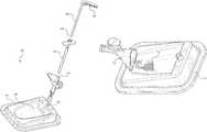
- FIG. 1shows an isometric view of a mixing system according to one embodiment
- FIG. 2shows an exploded view of the mixing system shown in FIG. 1 ;
- FIG. 3shows a front isometric view of a tray
- FIGS. 4A-4Bshow isometric views of a connector
- FIG. 5shows an isometric view of a mixing apparatus with mixed material
- FIG. 6shows an isometric view of a pushing assembly according to one embodiment
- FIG. 7shows an isometric view of the pushing assembly of FIG. 6 without a stylet
- FIG. 8shows an isometric view of a scooper connection according to one embodiment
- FIG. 9shows an isometric view of a scooper connection according to another embodiment
- FIG. 10shows an isometric view of a pushing assembly according to one embodiment
- FIG. 11shows a view of a pushing assembly with a stylet
- FIG. 12shows an isometric view of the pushing assembly in FIG. 11 ;
- FIG. 13Ashows an isometric view of a tubular member
- FIG. 13Bshows an isometric view of a tubular member handle
- FIG. 13Cshows another isometric view of the handle shown in FIG. 13B ;
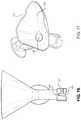
- FIG. 14shows an isometric view of a scooper
- FIG. 15shows another isometric view of the scooper shown in FIG. 14 ;
- FIG. 16shows a front perspective view of the scooper shown in FIGS. 14-15 ;
- FIG. 17shows a top isometric view from of the scooper shown in FIGS. 14-16 ;
- FIG. 18shows another isometric view of the scooper shown in FIGS. 14-17 ;
- FIG. 19shows a scooper sliding against the tray according to one embodiment.
- a mixing systemmay be used to prepare materials.
- the mixing systemmay be disposable and designed for single use.
- the mixing systemmay be used to prepare a single material, or it may be used to prepare and mix multiple materials together.
- a scooper having a large proximal opening that mates with a mixing trayreceives the mixed material.
- the scoopermay then secure to the mixing tray to provide a rigid support for the scooper while a tubular member is inserted into the scooper to receive the mixed material.
- the scoopermay be secured to the tubular member and the mixed material may be pushed into the tubular member.
- This versatilityallows the user to determine how to transfer the mixed material depending on the material characteristics (e.g. viscosity), surgical need, and personal preference with minimal waste of the mixed material.
- proximal and distalgenerally refer to positions or directions toward and away from, respectively, an individual using the mixing system.
- axialgenerally refer to positions or directions toward and away from, respectively, an individual using the mixing system.
- axialgenerally refers to positions or directions toward and away from, respectively, an individual using the mixing system.
- axialgenerally refers to positions or directions toward and away from, respectively, an individual using the mixing system.
- axialgenerally refers to positions or directions toward and away from, respectively, an individual using the mixing system.
- axialaxial
- verticallongitudinal
- leftleft
- rightaboveve
- belowdesignate directions in the drawings to which reference is made.
- substantiallyis intended to mean considerable in extent or largely but not necessarily wholly that which is specified.
- the terminologyincludes the above-listed words, derivatives thereof and words of similar import.
- the mixing systemmay include a mixing tray 101 , a scooper 130 , a tubular member 150 , and a stylet 160 .
- a mixing tray 101defines a mixing receptacle 104 and a connector receptacle 102 .
- the mixing receptacle 104may be concave. In aspects where a material 10 to be mixed is viscous, the concave shape of the mixing receptacle 104 facilitates mixing and prevents spillage.
- the mixing receptacle 104may define a curved surface, a prismatic surface, or be substantially flat to facilitate cutting, chopping or other manipulation of the material 10 .
- the mixing receptacle 104may include separate segments that vary in surface shape and dimension, such that a portion of the mixing receptacle 104 may be flat while another portion of the mixing receptacle 104 may be concave.
- the mixing tray 101may include multiple mixing receptacles 104 .
- the mixing tray 101may be made of polyethylene terephthalate (PET), polypropylene, acrylonitrile butadiene styrene (ABS), polyethylene terephthalate glycol-modified (PETG), a combination thereof, or another suitable polymer. In embodiments where the mixing tray is not disposable, it may be made of a metal.
- the connector receptacle 102may be sized and shaped to releasably receive a connector 180 or, in some embodiments, the connector 180 may be integral with the mixing tray 101 . Referring to FIGS. 3-4B , the connector receptacle 102 may define a channel 108 that is configured to slidably engage with a corresponding tab 188 on the connector 180 .
- the connector 180may be releasably secured into the connector receptacle 102 via a friction fit and/or using tabs 188 .
- the connector 180includes two tabs 188 that are positioned opposite one another.
- the connector 180may be secured to the mixing tray 101 using glue, screws, or other suitable couplers.
- the connector 180may be made from a material that is more rigid than the mixing tray 101 .
- the connector 180can define a channel 184 enabling air or liquid to leave the mixing system 100 .
- a portion of the material 10may also move along channel 184 to exit the mixing system 100 .
- the connector 180may include a plurality of channels 184 that may be either separately defined or connected to one another.
- the connector 180may include one or more tabs 182 radially extending from the body 181 of the connector 180 .
- the tabs 182may engage with a scooper 130 to releasably secure the scooper 130 with the connector 180 .
- the scooper 130has a proximal end 132 defining a proximal opening 133 , a distal end 134 defining a distal opening 135 , and a passage 136 extending longitudinally there between.
- the proximal opening 133may be larger than the distal opening 135 .
- the proximal opening 133can receive a portion of the material 10 from the mixing tray 101 .
- the proximal end 132has the largest cross-sectional area at its proximal-most region and has its smallest cross-sectional area at its distal-most region.
- the proximal end 132may function like a funnel so that material 10 introduced into proximal opening 133 may be funneled through the passage 136 into the distal end 134 . It will be appreciated that the dimensions of the passage 136 may be such that they accommodate the desired amount of material, and this disclosure is not limited to a particular size or shape of the passage 136 or the volume of desired material 10 to be introduced therein.
- the proximal end 132may include a notch 146 configured to slidably receive the stylet 160 to retain an unused portion of material 10 within the proximal opening 133 .
- the proximal end 132may include a tapered edge 148 .
- tapered edge 148is located at the proximal end 132 and is proximally tapered. The tapered edge 148 assists with collecting the material 10 into the scooper 130 .
- the scooper 130may include a plurality of tapered edges 148 to receive material from various sides of the proximal end 132 .
- the tapered edge 148may include an anti-stick coating to reduce friction between the scooper 130 and the material 10 .
- the scooper 130may further define an aperture 147 to vent air trapped within the material 10 inside the passage 136 .
- the aperture 147may be located on the proximal end 132 of the scooper 130 or, preferably, on the distal end 134 of the scooper 130 . Referring to FIG. 16 , the aperture 147 may be substantially round in shape, or have another shape and/or diameter that allow air to pass while preventing the material 10 from passing. In some embodiments, aperture 147 may include a semi-permeable cover (not shown), for example a net or mesh, that allows air to pass while preventing material 10 from passing.
- the scooper 130may include a grip 142 .
- the grip 142may be ring-shaped, or it may be T-shaped.
- a usermay slide a finger, such as an index finger through an opening in the grip 142 while placing another finger, such as a thumb, on a rest adjacent the opening.
- the scooper 130may not include the grip 142 and may be instead grasped by the proximal end 132 or the distal end 134 .
- the proximal end 132 of scooper 130is shaped to complement the shape of the mixing receptacle 104 of mixing tray 101 so that the material 10 from the mixing tray 101 may effectively be moved into the scooper 130 .
- the complementary shape of the proximal end 132maximizes the perimeter of the proximal end 132 that slides against the mixing receptacle 104 to receive the material 10 , as shown in FIG. 19 .
- the scooper 130may be releasably secured to the connector 180 .
- the scooper 130may include a groove 140 at the distal end 134 that receives the tab 182 on the connector 180 .
- the tab 182may pass into a cavity 137 and then into the groove 140 upon relative rotation of the scooper 130 and the connector 180 to releasably secure the scooper 130 to the connector 180 .
- the scooper 130is also removably attached to the mixing tray 101 by virtue of its attachment to connector 180 .
- translational movement of the scooper 130 relative to the connector 180is inhibited.
- the distal end 134 of the scooper 130may rotate independent of the rest of scooper 130 , and in such embodiments, it may be sufficient to only rotate the distal end 134 to slide the groove 140 over the tab 182 .
- Two tabs 182are shown in FIGS. 4A-4B and, therefore, scooper 130 includes two grooves 140 in FIG. 18 .
- the groove 140may not include the cavity 137 , such that the groove 140 has a closed circumference.
- the tab 182may have a variable protrusion length so it can retract to be received within the distal opening 135 and resiliently extend to be received within the groove 140 .
- the tab 182may include a spring to resiliently extend the tab 182 .
- the mixing system 100may also include the tubular member 150 .
- the tubular member 150has a tubular body 151 , a proximal end 152 having proximal opening 153 , and a distal end 154 having distal opening 155 .
- the tubular body 151defines a lumen 156 extending through the tubular body 151 between the proximal opening 153 and the distal opening 155 .
- the lumen 156is sized to receive the material 10 .
- the tubular member 150has an outer diameter that is smaller than the inner diameter of the scooper passage 136 , such that tubular member 150 can pass into the passage 136 .
- the tubular member 150may include markings (not shown) on the tubular body 151 .
- the markingsmay include measurements, material information, dates, or other information.
- the markingsmay be printed, they may be protrusions, or they may be notches on the tubular body 151 .
- the markingsmay be radio-opaque such that they are readily observable under X-ray or other radiation.
- the tubular member 150may be at least partially translucent. As such, a user can visualize the amount of material inside the lumen 156 under radiation.
- the distal end of the tubular member 150may releasably secure to other devices, such as a syringe or another tubular member 150 .
- the tubular member 150may include a closure cap (not shown) configured to removably attached to the proximal end 152 , the distal end 154 , or both ends.
- distal end 154 of tubular member 150may beveled to guide the material 10 entering the tubular member towards the center of the lumen 156 .
- the tubular member 150may also include a handle 170 .
- proximal end 174may define a proximal opening 175
- distal end 176may define a distal opening 177 .
- the body 171may further define a lumen extending between proximal opening 175 and distal opening 177 .
- the handle 170includes a distal opening 177 but not a proximal opening. Distal opening 177 of handle 170 may be sized to receive the proximal end 152 of tubular member 150 .
- Tubular member 150may be wedgedly secured to handle 170 .
- tubular member 150may be fastened to handle 170 with glue, screws, clips, or other suitable fasteners.
- the tubular member 150 and the handle 170may be a unitary piece.
- the mixing tray 101may include an attachment post 190 configured to receive the tubular member 150 at the distal end 154 .
- the attachment post 190may be shaped and dimensioned such that it has clearance to pass into the distal opening 155 such that the tubular member 150 is removably secured to the mixing tray 101 via the attachment post 190 .
- the tubular member 150may be secured to the attachment post 190 by any suitable method, for example, by threaded engagement, snap fit, interference fit, or another suitable method of securing the tubular member 150 to the attachment post 190 .
- the attachment post 190may be dimensioned such that it has enough clearance to pass into the distal opening 155 , but not so much clearance that the tubular member 150 is unsecured (e.g. wobbles or slides off the attachment post 190 ).
- the attachment post 190allows the user to introduce material into the tubular member 150 without having to also hold the tubular member 150 .
- the mixing tray 101acts as a base to prevent the tubular member 150 from falling or tipping, which decreases the chance of spilling the material and/or contaminating the surrounding environment.
- the attachment post 190may also provide a rigid floor to the tubular member 150 at the distal end 154 to allow the material to be compacted properly and to avoid under-filling or formation of air pockets within the material in the tubular member 150 .
- the attachment post 190may be dimensioned such that it may receive the distal end 154 rather than be received into the distal opening 155 .
- the attachment post 190may have an opening (not shown) into which the tubular member 150 may be inserted and secured via one of the methods described above.
- attachment post 190 and the connector 180are described as individual components, it will be understood that in some embodiments, the two components may be interchangeable, and the mixing system 100 may include one or more of the connectors 180 or attachment posts 190 . In some embodiments, for example, only one component (either the connector 180 or the attachment post 190 ) may be present and serve the role of both as described herein.
- the handle 170may include a tab 172 or a plurality of tabs 172 , such as two tabs 172 opposite one other on the body 171 .
- the tabs 172may be substantially similar in size, shape, and function as tabs 182 described above in connection with the connector 180 .
- the tabs 172may engage with the distal end 134 of scooper 130 , similar to the engagement of the tabs 182 .
- the proximal opening 175 of handle 170may be in fluid communication the distal opening 135 of the scooper 130 such that material 10 within the scooper 130 may pass from the distal opening 135 into the proximal opening 175 of the handle 170 .
- the mixing system 100may also include the stylet 160 .
- the stylet 160may include a stylet handle 162 configured to be received within the hand of the user.
- the stylet handle 162may define regions to receive a plurality of the user's fingers.
- the stylet 160has an outer diameter that is smaller than an inner diameter of the lumen 156 of the tubular member 150 and the passage 136 of the scooper 130 . As such, the stylet 160 may pass through the lumen 156 or the passage 136 .
- the stylet 160can be used as a plunger to push material through the tubular member 150 or the scooper 130 .
- the stylet 160may be sloped or tapered at its distal end 168 .
- the slope or tapermay be angled such that when the distal end 168 contacts the material in the tubular member 150 or in the scooper 130 , the material is pushed farther in the direction of movement of the stylet 160 .
- the distal end 168may be concave, such that the material is pushed towards the centerline of the stylet 160 as the stylet 160 is moved axially in the tubular member 150 or the scooper 130 .
- the distal end 168may be convex, such that the material is pushed away from the centerline of the stylet 160 .
- Various advantagesmay exist for different stylet shapes, such as increased precision when dispensing material, better spreading of the material within the tubular member 150 and/or the scooper 130 , and reduced clogging of the material inside the components of the mixing system 100 .
- the stylet 160may include markings (not shown) to indicate measurements, material information, or part reference numbers.
- the markingsmay be printed, protrusions or notches, and may be radio-opaque. In some embodiments, therefore, as the stylet 160 passes through the lumen 156 of the tubular member 150 , the markings on the distal end 168 of stylet 160 can be observed relative to the radio-opaque markings on the tubular body 151 .
- the components of mixing system 100may all be manufactured from the same material, or alternatively, may comprise different materials.
- Manufacturing materialsmay comprise plastic or metal, or a combination of plastic or metal.
- Materials usedmay include polyethylene terephthalate (PET), polyethylene terephthalate glycol-modified (PETG), polypropylene, acrylonitrile butadiene styrene (ABS), or another suitable polymer.
- combinations of materialsmay be used.
- Some embodimentsmay comprise materials that are at least partly translucent.
- the materialsmay be suitable for sterilization via autoclaving, ethylene oxide exposure, gamma ray radiation, or another suitable method of sterilization that can be used in the medical field.
- a portion of the mixing system or the entire system itselfmay be designed to be reusable. Alternatively, a portion of the system or the entire system may be disposable.
- the material 10may be moved into scooper 130 .
- the proximal end 132 of the scooper 130is positioned adjacent the mixing receptacle 104 .
- the scooper 130may be moved along the surface of the mixing receptacle 104 such that material is transferred from the mixing receptacle into proximal opening 133 .
- the material 10may be similarly moved into the proximal end 132 by an external tool (not shown) that urges the material 10 from the mixing receptacle 104 into the scooper 130 .
- the scooper 130may be removably attached to the connector 180 , as described above, where the connector 180 is already attached to the mixing tray 101 .
- the tubular member 150may then be introduced into the proximal opening 133 of scooper 130 and moved in a distal direction to receive the material 10 within its lumen 156 .
- the tubular member 150may be detached from the connector 180 and introduced to a surgical site.
- the stylet 160may be introduced into the proximal opening 153 of the tubular member 150 and moved distally through the lumen 156 to move a portion of the material 10 into the surgical site through the distal opening 155 of the tubular member 150 .
- the stylet 160may be used to push the material 10 out of the distal opening 135 of the scooper 130 into the lumen 156 of tubular member 150 .
Landscapes
- Health & Medical Sciences (AREA)
- Orthopedic Medicine & Surgery (AREA)
- Life Sciences & Earth Sciences (AREA)
- Surgery (AREA)
- General Health & Medical Sciences (AREA)
- Veterinary Medicine (AREA)
- Engineering & Computer Science (AREA)
- Biomedical Technology (AREA)
- Heart & Thoracic Surgery (AREA)
- Public Health (AREA)
- Animal Behavior & Ethology (AREA)
- Transplantation (AREA)
- Nuclear Medicine, Radiotherapy & Molecular Imaging (AREA)
- Medical Informatics (AREA)
- Molecular Biology (AREA)
- Vascular Medicine (AREA)
- Oral & Maxillofacial Surgery (AREA)
- Cardiology (AREA)
- Physical Education & Sports Medicine (AREA)
- Surgical Instruments (AREA)
Abstract
Description
Claims (13)
Priority Applications (2)
| Application Number | Priority Date | Filing Date | Title |
|---|---|---|---|
| US15/907,083US10722384B2 (en) | 2017-03-01 | 2018-02-27 | Medical material mixer and transfer apparatus and method for using the same |
| PCT/US2018/020230WO2018160697A1 (en) | 2017-03-01 | 2018-02-28 | Medical material mixer and transfer apparatus and method for using the same |
Applications Claiming Priority (2)
| Application Number | Priority Date | Filing Date | Title |
|---|---|---|---|
| US201762465251P | 2017-03-01 | 2017-03-01 | |
| US15/907,083US10722384B2 (en) | 2017-03-01 | 2018-02-27 | Medical material mixer and transfer apparatus and method for using the same |
Publications (2)
| Publication Number | Publication Date |
|---|---|
| US20180250145A1 US20180250145A1 (en) | 2018-09-06 |
| US10722384B2true US10722384B2 (en) | 2020-07-28 |
Family
ID=63357088
Family Applications (1)
| Application Number | Title | Priority Date | Filing Date |
|---|---|---|---|
| US15/907,083Expired - Fee RelatedUS10722384B2 (en) | 2017-03-01 | 2018-02-27 | Medical material mixer and transfer apparatus and method for using the same |
Country Status (2)
| Country | Link |
|---|---|
| US (1) | US10722384B2 (en) |
| WO (1) | WO2018160697A1 (en) |
Families Citing this family (6)
| Publication number | Priority date | Publication date | Assignee | Title |
|---|---|---|---|---|
| US10722384B2 (en)* | 2017-03-01 | 2020-07-28 | Nordson Corporation | Medical material mixer and transfer apparatus and method for using the same |
| US10709576B2 (en)* | 2017-04-28 | 2020-07-14 | Warsaw Orthopedic, Inc. | Bone material dispensing apparatus and methods |
| US11583403B2 (en) | 2019-11-15 | 2023-02-21 | Warsaw Orthopedic, Inc. | Bone implant holding and shaping tray |
| US12329430B2 (en) | 2021-07-19 | 2025-06-17 | Warsaw Orthopedic, Inc. | Bone material dispensing system and methods of use |
| US11969194B2 (en) | 2021-07-19 | 2024-04-30 | Warsaw Orthopedic, Inc. | Bone material dispensing system and methods of use |
| US12144744B2 (en) | 2021-07-19 | 2024-11-19 | Warsaw Orthopedic, Inc. | Bone material dispensing device with distal frame |
Citations (67)
| Publication number | Priority date | Publication date | Assignee | Title |
|---|---|---|---|---|
| US3317274A (en)* | 1963-05-22 | 1967-05-02 | Miles Lab | Device for supporting a clinical thermometer |
| US4277184A (en)* | 1979-08-14 | 1981-07-07 | Alan Solomon | Disposable orthopedic implement and method |
| US4294349A (en)* | 1978-07-21 | 1981-10-13 | Den-Mat, Inc. | Kit for repair of porcelain dental prostheses |
| US4420085A (en)* | 1982-01-15 | 1983-12-13 | The Kendall Company | Stand up organizer |
| US4761379A (en)* | 1984-08-09 | 1988-08-02 | Becton, Dickinson And Company | Biological specimen collection device |
| US4844249A (en)* | 1988-06-03 | 1989-07-04 | Maurice Coulombe | Medical supplies container |
| US4852584A (en)* | 1988-10-11 | 1989-08-01 | Selby Charles R | Fluid collection tube with a safety funnel at its open end |
| US4961500A (en)* | 1989-12-18 | 1990-10-09 | Maurice Coulombe | Medical dispenser tray |
| US4997084A (en)* | 1988-05-13 | 1991-03-05 | Opielab, Inc. | Packaging system for disposable endoscope sheaths |
| US5007535A (en)* | 1988-09-26 | 1991-04-16 | Hammerlit Gmbh | Syringe tray |
| US5024326A (en)* | 1989-05-24 | 1991-06-18 | Devon Industries, Inc. | Medical instrument holder and sharps disposal container |
| US5201418A (en)* | 1991-08-16 | 1993-04-13 | Ronnie Hanlon | Needle disposal system |
| US5203459A (en)* | 1991-05-14 | 1993-04-20 | Wade Leslie C | Prepackaged oral medication serving apparatus and method |
| US5240415A (en)* | 1990-06-07 | 1993-08-31 | Haynie Michel B | Dental bleach system having separately compartmented fumed silica and hydrogen peroxide and method of using |
| US5449071A (en)* | 1993-10-28 | 1995-09-12 | Levy; Abner | Tray for medical specimen collection kit |
| US5586821A (en)* | 1995-10-10 | 1996-12-24 | Zimmer, Inc. | Bone cement preparation kit |
| US5868250A (en)* | 1996-09-26 | 1999-02-09 | Brackett; Fred | Tray for holding medical instruments |
| US5975305A (en)* | 1998-06-25 | 1999-11-02 | Comar, Inc. | Unit dose spoon |
| US6364519B1 (en)* | 2000-09-26 | 2002-04-02 | Smith & Nephew, Inc. | Bone cement system |
| US6435705B1 (en) | 1999-04-16 | 2002-08-20 | Depuy Orthopaedics, Inc. | Apparatus and method for delivering and mixing a liquid bone cement component with a powder bone cement component |
| US6458147B1 (en)* | 1998-11-06 | 2002-10-01 | Neomend, Inc. | Compositions, systems, and methods for arresting or controlling bleeding or fluid leakage in body tissue |
| US20020191487A1 (en)* | 2000-10-25 | 2002-12-19 | Kyphon Inc. | Systems and methods for mixing and transferring flowable materials |
| US6536937B1 (en)* | 2000-02-14 | 2003-03-25 | Telios Orthopedic Systems, Inc. | Self-contained base for a surgical cement mixing system, binding material mixing base, and surgical bone cement mixing system |
| US6588587B2 (en)* | 1999-12-21 | 2003-07-08 | Cobe Cardiovascular, Inc. | Packaging system for medical components |
| US20040010260A1 (en)* | 1998-08-14 | 2004-01-15 | Kyphon Inc. | Systems and methods for placing materials into bone |
| US6779657B2 (en)* | 2001-06-06 | 2004-08-24 | Closure Medical Corporation | Single-use applicators, dispensers and methods for polymerizable monomer compound |
| US20040195131A1 (en)* | 2003-04-03 | 2004-10-07 | Medical Components, Inc. | Snap tray for medical accessories |
| WO2004100741A1 (en) | 2003-05-13 | 2004-11-25 | Randall Cornfield | Ergonomic ladle |
| US20040238391A1 (en)* | 2003-05-30 | 2004-12-02 | Inter-Med, Inc. | Package construction for fluid applicator device |
| US20040267277A1 (en)* | 2003-06-30 | 2004-12-30 | Zannis Anthony D. | Implant delivery instrument |
| USD500850S1 (en)* | 2000-03-08 | 2005-01-11 | Eu Pharma Limited | Medicine dispenser |
| US20050011805A1 (en)* | 2003-07-14 | 2005-01-20 | Polly Lyons | Paint touch-up kit |
| US20050034310A1 (en) | 2003-08-15 | 2005-02-17 | Conforti Terry J. | Kitchen utensil |
| US20050155901A1 (en)* | 2004-01-21 | 2005-07-21 | Krueger John A. | Surgical cement preparation system |
| US6957909B1 (en)* | 1999-07-24 | 2005-10-25 | Smith & Nephew, Inc. | Blister pack |
| US20050241965A1 (en)* | 2004-04-30 | 2005-11-03 | Dentak | Kit for preparing a bone filler mixture, a cartridge specially adapted to said kit, and an implantation set including said kit |
| WO2007122006A1 (en) | 2006-04-26 | 2007-11-01 | Summit Medical Limited | A medical treatment material delivery apparatus |
| US7308985B2 (en)* | 2004-07-14 | 2007-12-18 | Scimed Life Systems, Inc. | Packaging for a kit, and related methods of use |
| US7331450B2 (en)* | 2004-11-30 | 2008-02-19 | Centrix, Inc. | Dental applicator holding and material dispensing tray |
| US20080045861A1 (en)* | 2002-05-31 | 2008-02-21 | Miller Larry J | Medical Procedures Trays And Related Methods |
| US20080105328A1 (en)* | 2002-11-20 | 2008-05-08 | Desmond James F | Travel storage systems |
| US20090194446A1 (en)* | 2006-09-12 | 2009-08-06 | Miller Larry J | Vertebral Access System and Methods |
| US20090277809A1 (en)* | 2004-10-08 | 2009-11-12 | Straumann Holding Ag | Package system for a powdery, granular, paste-like or liquid sterile product |
| US20090283441A1 (en)* | 2008-05-19 | 2009-11-19 | Peter Santaw | Cosmetics kit |
| US20110071536A1 (en)* | 2009-09-18 | 2011-03-24 | Kleiner Jeffrey | Bone graft delivery device and method of using the same |
| USD636890S1 (en)* | 2009-09-17 | 2011-04-26 | Sands Innovations Pty. Ltd. | Dispensing utensil |
| WO2011159869A2 (en) | 2010-06-18 | 2011-12-22 | Warsaw Orthopedic, Inc. | Bone replacement material mixing and delivery devices and methods of use |
| US8246572B2 (en)* | 2009-12-23 | 2012-08-21 | Lary Research & Development, Llc | Bone graft applicator |
| US8303599B2 (en)* | 2006-01-30 | 2012-11-06 | Stryker Leibinger Gmbh & Co. Kg | Syringe |
| CN202723953U (en) | 2012-07-12 | 2013-02-13 | 北京爱康宜诚医疗器材股份有限公司 | Stirring device for bone cement |
| US8425619B2 (en)* | 2002-06-13 | 2013-04-23 | Kensey Nash Bvf Technology, Llc | Devices and methods for treating defects in the tissue of a living being |
| US8511500B2 (en)* | 2010-06-07 | 2013-08-20 | Sands Innovations Pty. Ltd. | Dispensing container |
| US8673021B2 (en)* | 2003-11-26 | 2014-03-18 | Depuy Mitek, Llc | Arthroscopic tissue scaffold delivery device |
| US8689972B2 (en)* | 2010-07-21 | 2014-04-08 | Multivac Sepp Haggenmueller Gmbh & Co. Kg | Packaging for a liquid, powdery or pasty product |
| US8714354B2 (en)* | 2010-03-25 | 2014-05-06 | Sdi North America Inc. | Liquid container |
| US20140188001A1 (en)* | 2006-09-12 | 2014-07-03 | Vidacare Corporation | Medical procedures trays and related methods |
| US20140262880A1 (en)* | 2013-03-15 | 2014-09-18 | Vidacare Corporation | Containment Assemblies, Methods, and Kits |
| CH708198A1 (en) | 2013-06-04 | 2014-12-15 | Medmix Systems Ag | System for producing a bone substitute material, comprising a container and a retaining member. |
| US20150075556A1 (en)* | 2013-09-19 | 2015-03-19 | Monifa L. Mortis Simons | Cosmetics storage assembly |
| US9107524B2 (en)* | 2011-08-29 | 2015-08-18 | Adam Leffler | Spoon delivery device |
| US9114201B2 (en)* | 2011-11-10 | 2015-08-25 | Panasonic Healthcare Holdings Co., Ltd. | Storage case for pharmaceutical syringe unit |
| US9212978B2 (en)* | 2004-11-24 | 2015-12-15 | Rongshan Li | Cytoblock preparation system and methods of use |
| US9283013B2 (en)* | 2013-03-14 | 2016-03-15 | Warsaw Orthopedic, Inc. | Filling systems for bone delivery devices |
| US9345639B2 (en)* | 2006-03-16 | 2016-05-24 | Kenneth D. Ferrara | System for facilitating preparation of medication doses |
| US9758284B2 (en)* | 2013-09-27 | 2017-09-12 | Barton Group, Inc. | Flexible container with integral extended internal dispensing tube in a stand-up configuration |
| US9815606B2 (en)* | 2015-04-29 | 2017-11-14 | Barton Group, Inc. | Flexible stand-up pouch container for flowable products |
| US20180250145A1 (en)* | 2017-03-01 | 2018-09-06 | Nordson Corporation | Medical material mixer and transfer apparatus and method for using the same |
- 2018
- 2018-02-27USUS15/907,083patent/US10722384B2/ennot_activeExpired - Fee Related
- 2018-02-28WOPCT/US2018/020230patent/WO2018160697A1/ennot_activeCeased
Patent Citations (77)
| Publication number | Priority date | Publication date | Assignee | Title |
|---|---|---|---|---|
| US3317274A (en)* | 1963-05-22 | 1967-05-02 | Miles Lab | Device for supporting a clinical thermometer |
| US4294349A (en)* | 1978-07-21 | 1981-10-13 | Den-Mat, Inc. | Kit for repair of porcelain dental prostheses |
| US4277184A (en)* | 1979-08-14 | 1981-07-07 | Alan Solomon | Disposable orthopedic implement and method |
| US4420085A (en)* | 1982-01-15 | 1983-12-13 | The Kendall Company | Stand up organizer |
| US4761379A (en)* | 1984-08-09 | 1988-08-02 | Becton, Dickinson And Company | Biological specimen collection device |
| US4997084A (en)* | 1988-05-13 | 1991-03-05 | Opielab, Inc. | Packaging system for disposable endoscope sheaths |
| US4844249A (en)* | 1988-06-03 | 1989-07-04 | Maurice Coulombe | Medical supplies container |
| US5007535A (en)* | 1988-09-26 | 1991-04-16 | Hammerlit Gmbh | Syringe tray |
| US4852584A (en)* | 1988-10-11 | 1989-08-01 | Selby Charles R | Fluid collection tube with a safety funnel at its open end |
| US5024326A (en)* | 1989-05-24 | 1991-06-18 | Devon Industries, Inc. | Medical instrument holder and sharps disposal container |
| US4961500A (en)* | 1989-12-18 | 1990-10-09 | Maurice Coulombe | Medical dispenser tray |
| US5240415A (en)* | 1990-06-07 | 1993-08-31 | Haynie Michel B | Dental bleach system having separately compartmented fumed silica and hydrogen peroxide and method of using |
| US5203459A (en)* | 1991-05-14 | 1993-04-20 | Wade Leslie C | Prepackaged oral medication serving apparatus and method |
| US5201418A (en)* | 1991-08-16 | 1993-04-13 | Ronnie Hanlon | Needle disposal system |
| US5449071A (en)* | 1993-10-28 | 1995-09-12 | Levy; Abner | Tray for medical specimen collection kit |
| US5586821A (en)* | 1995-10-10 | 1996-12-24 | Zimmer, Inc. | Bone cement preparation kit |
| US5868250A (en)* | 1996-09-26 | 1999-02-09 | Brackett; Fred | Tray for holding medical instruments |
| US5975305A (en)* | 1998-06-25 | 1999-11-02 | Comar, Inc. | Unit dose spoon |
| US20040010260A1 (en)* | 1998-08-14 | 2004-01-15 | Kyphon Inc. | Systems and methods for placing materials into bone |
| US6458147B1 (en)* | 1998-11-06 | 2002-10-01 | Neomend, Inc. | Compositions, systems, and methods for arresting or controlling bleeding or fluid leakage in body tissue |
| US6435705B1 (en) | 1999-04-16 | 2002-08-20 | Depuy Orthopaedics, Inc. | Apparatus and method for delivering and mixing a liquid bone cement component with a powder bone cement component |
| US6957909B1 (en)* | 1999-07-24 | 2005-10-25 | Smith & Nephew, Inc. | Blister pack |
| US6588587B2 (en)* | 1999-12-21 | 2003-07-08 | Cobe Cardiovascular, Inc. | Packaging system for medical components |
| US6536937B1 (en)* | 2000-02-14 | 2003-03-25 | Telios Orthopedic Systems, Inc. | Self-contained base for a surgical cement mixing system, binding material mixing base, and surgical bone cement mixing system |
| USD500850S1 (en)* | 2000-03-08 | 2005-01-11 | Eu Pharma Limited | Medicine dispenser |
| US6364519B1 (en)* | 2000-09-26 | 2002-04-02 | Smith & Nephew, Inc. | Bone cement system |
| US7278778B2 (en)* | 2000-10-25 | 2007-10-09 | Kyphon Inc. | System for mixing and transferring flowable materials |
| US20080033447A1 (en)* | 2000-10-25 | 2008-02-07 | Kyphon Inc. | Systems, methods and kits for mixing and transferring flowable materials |
| US20020191487A1 (en)* | 2000-10-25 | 2002-12-19 | Kyphon Inc. | Systems and methods for mixing and transferring flowable materials |
| US7160020B2 (en)* | 2000-10-25 | 2007-01-09 | Kyphon Inc. | Methods for mixing and transferring flowable materials |
| US6779657B2 (en)* | 2001-06-06 | 2004-08-24 | Closure Medical Corporation | Single-use applicators, dispensers and methods for polymerizable monomer compound |
| US20080045861A1 (en)* | 2002-05-31 | 2008-02-21 | Miller Larry J | Medical Procedures Trays And Related Methods |
| US8425619B2 (en)* | 2002-06-13 | 2013-04-23 | Kensey Nash Bvf Technology, Llc | Devices and methods for treating defects in the tissue of a living being |
| US8435306B2 (en)* | 2002-06-13 | 2013-05-07 | Kensey Nash Bvf Technology Llc | Devices and methods for treating defects in the tissue of a living being |
| US20080105328A1 (en)* | 2002-11-20 | 2008-05-08 | Desmond James F | Travel storage systems |
| US20040195131A1 (en)* | 2003-04-03 | 2004-10-07 | Medical Components, Inc. | Snap tray for medical accessories |
| US6880590B2 (en) | 2003-05-13 | 2005-04-19 | Randall Cornfield | Ergonomic ladle |
| WO2004100741A1 (en) | 2003-05-13 | 2004-11-25 | Randall Cornfield | Ergonomic ladle |
| US20040238391A1 (en)* | 2003-05-30 | 2004-12-02 | Inter-Med, Inc. | Package construction for fluid applicator device |
| US20040267277A1 (en)* | 2003-06-30 | 2004-12-30 | Zannis Anthony D. | Implant delivery instrument |
| US20050011805A1 (en)* | 2003-07-14 | 2005-01-20 | Polly Lyons | Paint touch-up kit |
| US20050034310A1 (en) | 2003-08-15 | 2005-02-17 | Conforti Terry J. | Kitchen utensil |
| US8673021B2 (en)* | 2003-11-26 | 2014-03-18 | Depuy Mitek, Llc | Arthroscopic tissue scaffold delivery device |
| US9827111B2 (en)* | 2003-11-26 | 2017-11-28 | Depuy Mitek, Llc | Arthroscopic tissue scaffold delivery device |
| US20050155901A1 (en)* | 2004-01-21 | 2005-07-21 | Krueger John A. | Surgical cement preparation system |
| US20050241965A1 (en)* | 2004-04-30 | 2005-11-03 | Dentak | Kit for preparing a bone filler mixture, a cartridge specially adapted to said kit, and an implantation set including said kit |
| US7308985B2 (en)* | 2004-07-14 | 2007-12-18 | Scimed Life Systems, Inc. | Packaging for a kit, and related methods of use |
| US20090277809A1 (en)* | 2004-10-08 | 2009-11-12 | Straumann Holding Ag | Package system for a powdery, granular, paste-like or liquid sterile product |
| US9212978B2 (en)* | 2004-11-24 | 2015-12-15 | Rongshan Li | Cytoblock preparation system and methods of use |
| US7331450B2 (en)* | 2004-11-30 | 2008-02-19 | Centrix, Inc. | Dental applicator holding and material dispensing tray |
| US8403936B2 (en)* | 2006-01-30 | 2013-03-26 | Stryker Leibinger Gmbh & Co. Kg | Syringe and stand |
| US8945134B2 (en)* | 2006-01-30 | 2015-02-03 | Stryker Leibinger Gmbh & Co. Kg | Syringe and stand |
| US8303599B2 (en)* | 2006-01-30 | 2012-11-06 | Stryker Leibinger Gmbh & Co. Kg | Syringe |
| US9345639B2 (en)* | 2006-03-16 | 2016-05-24 | Kenneth D. Ferrara | System for facilitating preparation of medication doses |
| US8696678B2 (en) | 2006-04-26 | 2014-04-15 | Summit Medical Limited | Medical treatment material delivery apparatus |
| WO2007122006A1 (en) | 2006-04-26 | 2007-11-01 | Summit Medical Limited | A medical treatment material delivery apparatus |
| US20090194446A1 (en)* | 2006-09-12 | 2009-08-06 | Miller Larry J | Vertebral Access System and Methods |
| US20140188001A1 (en)* | 2006-09-12 | 2014-07-03 | Vidacare Corporation | Medical procedures trays and related methods |
| US20090283441A1 (en)* | 2008-05-19 | 2009-11-19 | Peter Santaw | Cosmetics kit |
| USD636890S1 (en)* | 2009-09-17 | 2011-04-26 | Sands Innovations Pty. Ltd. | Dispensing utensil |
| US20110071536A1 (en)* | 2009-09-18 | 2011-03-24 | Kleiner Jeffrey | Bone graft delivery device and method of using the same |
| US8246572B2 (en)* | 2009-12-23 | 2012-08-21 | Lary Research & Development, Llc | Bone graft applicator |
| US8714354B2 (en)* | 2010-03-25 | 2014-05-06 | Sdi North America Inc. | Liquid container |
| US8511500B2 (en)* | 2010-06-07 | 2013-08-20 | Sands Innovations Pty. Ltd. | Dispensing container |
| US8408250B2 (en) | 2010-06-18 | 2013-04-02 | Warsaw Orthopedic, Inc. | Bone replacement material mixing and delivery devices and methods of use |
| WO2011159869A2 (en) | 2010-06-18 | 2011-12-22 | Warsaw Orthopedic, Inc. | Bone replacement material mixing and delivery devices and methods of use |
| US8689972B2 (en)* | 2010-07-21 | 2014-04-08 | Multivac Sepp Haggenmueller Gmbh & Co. Kg | Packaging for a liquid, powdery or pasty product |
| US9107524B2 (en)* | 2011-08-29 | 2015-08-18 | Adam Leffler | Spoon delivery device |
| US9114201B2 (en)* | 2011-11-10 | 2015-08-25 | Panasonic Healthcare Holdings Co., Ltd. | Storage case for pharmaceutical syringe unit |
| CN202723953U (en) | 2012-07-12 | 2013-02-13 | 北京爱康宜诚医疗器材股份有限公司 | Stirring device for bone cement |
| US9283013B2 (en)* | 2013-03-14 | 2016-03-15 | Warsaw Orthopedic, Inc. | Filling systems for bone delivery devices |
| US20140262880A1 (en)* | 2013-03-15 | 2014-09-18 | Vidacare Corporation | Containment Assemblies, Methods, and Kits |
| CH708198A1 (en) | 2013-06-04 | 2014-12-15 | Medmix Systems Ag | System for producing a bone substitute material, comprising a container and a retaining member. |
| US20150075556A1 (en)* | 2013-09-19 | 2015-03-19 | Monifa L. Mortis Simons | Cosmetics storage assembly |
| US9758284B2 (en)* | 2013-09-27 | 2017-09-12 | Barton Group, Inc. | Flexible container with integral extended internal dispensing tube in a stand-up configuration |
| US9815606B2 (en)* | 2015-04-29 | 2017-11-14 | Barton Group, Inc. | Flexible stand-up pouch container for flowable products |
| US20180250145A1 (en)* | 2017-03-01 | 2018-09-06 | Nordson Corporation | Medical material mixer and transfer apparatus and method for using the same |
Non-Patent Citations (1)
| Title |
|---|
| ISA/220—Notification of Transmittal of Search Report and Written Opinion of the ISA dated Jun. 8, 2018 for WO Application No. PCT/US18/020230. |
Also Published As
| Publication number | Publication date |
|---|---|
| WO2018160697A1 (en) | 2018-09-07 |
| US20180250145A1 (en) | 2018-09-06 |
Similar Documents
| Publication | Publication Date | Title |
|---|---|---|
| US10722384B2 (en) | Medical material mixer and transfer apparatus and method for using the same | |
| US10687828B2 (en) | Bone graft delivery system and method for using same | |
| US7214206B2 (en) | Implanting device and method of using same | |
| US9681889B1 (en) | Depth controlled needle assembly | |
| DE69829087T2 (en) | Kit for implanting an implant | |
| CA2413665C (en) | Multi-use surgical cement dispenser apparatus and kit for same | |
| AU2009225637B2 (en) | Sharps container | |
| US20090255839A1 (en) | Sharps container for safe transportation and dispensing of unused pen needle assemblies and for safe storage of used pen needle assemblies | |
| EP3010633B1 (en) | Device and method for improving hydration of a biomaterial | |
| US20110159457A1 (en) | Blood absorbing device | |
| CA2527118A1 (en) | Controlled orifice sampling needle | |
| CN109069808A (en) | Medical bolt delivery apparatus and associated components and method with rotatable magazine | |
| KR20180051402A (en) | Drug pellet delivery system and method | |
| US9827113B2 (en) | Graft delivery system and methods thereof | |
| WO2004091453A1 (en) | An orbital implant applicator | |
| US20250099149A1 (en) | Temporary Antimicrobial Cement Spacer, Assembly, Kit, And Method Of Manufacture | |
| DE102013111194A1 (en) | Surgical instrument handpiece, as well as surgical instrument and surgical set with such an instrument handpiece | |
| EP3672680B1 (en) | Device for implanting objects under skin | |
| US10980588B2 (en) | Modular discharge device with separator element | |
| US20050115980A1 (en) | Container for holding sterile goods and sterile goods dispenser | |
| US10653470B2 (en) | Compressible mixing and delivery system for medical substances | |
| CN221866141U (en) | Tissue repair material pusher and tissue repair kit | |
| JP2017532182A (en) | Device for applying bone replacement paste | |
| AU2008207386A1 (en) | Multi-use surgical cement dispenser apparatus |
Legal Events
| Date | Code | Title | Description |
|---|---|---|---|
| FEPP | Fee payment procedure | Free format text:ENTITY STATUS SET TO UNDISCOUNTED (ORIGINAL EVENT CODE: BIG.); ENTITY STATUS OF PATENT OWNER: LARGE ENTITY | |
| AS | Assignment | Owner name:NORDSON CORPORATION, OHIO Free format text:ASSIGNMENT OF ASSIGNORS INTEREST;ASSIGNORS:STEVENSON, MARK;HOOGENAKKER, JON E.;CROMETT, ALEX;AND OTHERS;SIGNING DATES FROM 20180314 TO 20180321;REEL/FRAME:045300/0869 | |
| STPP | Information on status: patent application and granting procedure in general | Free format text:DOCKETED NEW CASE - READY FOR EXAMINATION | |
| STPP | Information on status: patent application and granting procedure in general | Free format text:NON FINAL ACTION MAILED | |
| STPP | Information on status: patent application and granting procedure in general | Free format text:RESPONSE TO NON-FINAL OFFICE ACTION ENTERED AND FORWARDED TO EXAMINER | |
| STPP | Information on status: patent application and granting procedure in general | Free format text:NOTICE OF ALLOWANCE MAILED -- APPLICATION RECEIVED IN OFFICE OF PUBLICATIONS | |
| STPP | Information on status: patent application and granting procedure in general | Free format text:PUBLICATIONS -- ISSUE FEE PAYMENT VERIFIED | |
| STCF | Information on status: patent grant | Free format text:PATENTED CASE | |
| FEPP | Fee payment procedure | Free format text:MAINTENANCE FEE REMINDER MAILED (ORIGINAL EVENT CODE: REM.); ENTITY STATUS OF PATENT OWNER: LARGE ENTITY | |
| LAPS | Lapse for failure to pay maintenance fees | Free format text:PATENT EXPIRED FOR FAILURE TO PAY MAINTENANCE FEES (ORIGINAL EVENT CODE: EXP.); ENTITY STATUS OF PATENT OWNER: LARGE ENTITY | |
| STCH | Information on status: patent discontinuation | Free format text:PATENT EXPIRED DUE TO NONPAYMENT OF MAINTENANCE FEES UNDER 37 CFR 1.362 | |
| FP | Lapsed due to failure to pay maintenance fee | Effective date:20240728 |