US10722252B2 - Subintimal catheter device, assembly and related methods - Google Patents
Subintimal catheter device, assembly and related methodsDownload PDFInfo
- Publication number
- US10722252B2 US10722252B2US16/160,162US201816160162AUS10722252B2US 10722252 B2US10722252 B2US 10722252B2US 201816160162 AUS201816160162 AUS 201816160162AUS 10722252 B2US10722252 B2US 10722252B2
- Authority
- US
- United States
- Prior art keywords
- catheter
- side tube
- central
- guidewire
- subintimal
- Prior art date
- Legal status (The legal status is an assumption and is not a legal conclusion. Google has not performed a legal analysis and makes no representation as to the accuracy of the status listed.)
- Active, expires
Links
Images


Classifications
- A—HUMAN NECESSITIES
- A61—MEDICAL OR VETERINARY SCIENCE; HYGIENE
- A61M—DEVICES FOR INTRODUCING MEDIA INTO, OR ONTO, THE BODY; DEVICES FOR TRANSDUCING BODY MEDIA OR FOR TAKING MEDIA FROM THE BODY; DEVICES FOR PRODUCING OR ENDING SLEEP OR STUPOR
- A61M25/00—Catheters; Hollow probes
- A61M25/01—Introducing, guiding, advancing, emplacing or holding catheters
- A61M25/0194—Tunnelling catheters
- A—HUMAN NECESSITIES
- A61—MEDICAL OR VETERINARY SCIENCE; HYGIENE
- A61B—DIAGNOSIS; SURGERY; IDENTIFICATION
- A61B17/00—Surgical instruments, devices or methods
- A61B17/22—Implements for squeezing-off ulcers or the like on inner organs of the body; Implements for scraping-out cavities of body organs, e.g. bones; for invasive removal or destruction of calculus using mechanical vibrations; for removing obstructions in blood vessels, not otherwise provided for
- A—HUMAN NECESSITIES
- A61—MEDICAL OR VETERINARY SCIENCE; HYGIENE
- A61B—DIAGNOSIS; SURGERY; IDENTIFICATION
- A61B17/00—Surgical instruments, devices or methods
- A61B17/00234—Surgical instruments, devices or methods for minimally invasive surgery
- A—HUMAN NECESSITIES
- A61—MEDICAL OR VETERINARY SCIENCE; HYGIENE
- A61B—DIAGNOSIS; SURGERY; IDENTIFICATION
- A61B90/00—Instruments, implements or accessories specially adapted for surgery or diagnosis and not covered by any of the groups A61B1/00 - A61B50/00, e.g. for luxation treatment or for protecting wound edges
- A61B90/39—Markers, e.g. radio-opaque or breast lesions markers
- A—HUMAN NECESSITIES
- A61—MEDICAL OR VETERINARY SCIENCE; HYGIENE
- A61B—DIAGNOSIS; SURGERY; IDENTIFICATION
- A61B17/00—Surgical instruments, devices or methods
- A61B17/00234—Surgical instruments, devices or methods for minimally invasive surgery
- A61B2017/00292—Surgical instruments, devices or methods for minimally invasive surgery mounted on or guided by flexible, e.g. catheter-like, means
- A—HUMAN NECESSITIES
- A61—MEDICAL OR VETERINARY SCIENCE; HYGIENE
- A61B—DIAGNOSIS; SURGERY; IDENTIFICATION
- A61B17/00—Surgical instruments, devices or methods
- A61B17/22—Implements for squeezing-off ulcers or the like on inner organs of the body; Implements for scraping-out cavities of body organs, e.g. bones; for invasive removal or destruction of calculus using mechanical vibrations; for removing obstructions in blood vessels, not otherwise provided for
- A61B2017/22038—Implements for squeezing-off ulcers or the like on inner organs of the body; Implements for scraping-out cavities of body organs, e.g. bones; for invasive removal or destruction of calculus using mechanical vibrations; for removing obstructions in blood vessels, not otherwise provided for with a guide wire
- A61B2017/22045—Implements for squeezing-off ulcers or the like on inner organs of the body; Implements for scraping-out cavities of body organs, e.g. bones; for invasive removal or destruction of calculus using mechanical vibrations; for removing obstructions in blood vessels, not otherwise provided for with a guide wire fixed to the catheter; guiding tip
- A—HUMAN NECESSITIES
- A61—MEDICAL OR VETERINARY SCIENCE; HYGIENE
- A61B—DIAGNOSIS; SURGERY; IDENTIFICATION
- A61B17/00—Surgical instruments, devices or methods
- A61B17/22—Implements for squeezing-off ulcers or the like on inner organs of the body; Implements for scraping-out cavities of body organs, e.g. bones; for invasive removal or destruction of calculus using mechanical vibrations; for removing obstructions in blood vessels, not otherwise provided for
- A61B2017/22051—Implements for squeezing-off ulcers or the like on inner organs of the body; Implements for scraping-out cavities of body organs, e.g. bones; for invasive removal or destruction of calculus using mechanical vibrations; for removing obstructions in blood vessels, not otherwise provided for with an inflatable part, e.g. balloon, for positioning, blocking, or immobilisation
- A—HUMAN NECESSITIES
- A61—MEDICAL OR VETERINARY SCIENCE; HYGIENE
- A61B—DIAGNOSIS; SURGERY; IDENTIFICATION
- A61B17/00—Surgical instruments, devices or methods
- A61B17/22—Implements for squeezing-off ulcers or the like on inner organs of the body; Implements for scraping-out cavities of body organs, e.g. bones; for invasive removal or destruction of calculus using mechanical vibrations; for removing obstructions in blood vessels, not otherwise provided for
- A61B2017/22094—Implements for squeezing-off ulcers or the like on inner organs of the body; Implements for scraping-out cavities of body organs, e.g. bones; for invasive removal or destruction of calculus using mechanical vibrations; for removing obstructions in blood vessels, not otherwise provided for for crossing total occlusions, i.e. piercing
- A61B2017/22095—Implements for squeezing-off ulcers or the like on inner organs of the body; Implements for scraping-out cavities of body organs, e.g. bones; for invasive removal or destruction of calculus using mechanical vibrations; for removing obstructions in blood vessels, not otherwise provided for for crossing total occlusions, i.e. piercing accessing a blood vessel true lumen from the sub-intimal space
- A—HUMAN NECESSITIES
- A61—MEDICAL OR VETERINARY SCIENCE; HYGIENE
- A61B—DIAGNOSIS; SURGERY; IDENTIFICATION
- A61B90/00—Instruments, implements or accessories specially adapted for surgery or diagnosis and not covered by any of the groups A61B1/00 - A61B50/00, e.g. for luxation treatment or for protecting wound edges
- A61B90/39—Markers, e.g. radio-opaque or breast lesions markers
- A61B2090/3966—Radiopaque markers visible in an X-ray image
- A—HUMAN NECESSITIES
- A61—MEDICAL OR VETERINARY SCIENCE; HYGIENE
- A61M—DEVICES FOR INTRODUCING MEDIA INTO, OR ONTO, THE BODY; DEVICES FOR TRANSDUCING BODY MEDIA OR FOR TAKING MEDIA FROM THE BODY; DEVICES FOR PRODUCING OR ENDING SLEEP OR STUPOR
- A61M25/00—Catheters; Hollow probes
- A61M25/01—Introducing, guiding, advancing, emplacing or holding catheters
- A61M2025/0177—Introducing, guiding, advancing, emplacing or holding catheters having external means for receiving guide wires, wires or stiffening members, e.g. loops, clamps or lateral tubes
- A—HUMAN NECESSITIES
- A61—MEDICAL OR VETERINARY SCIENCE; HYGIENE
- A61M—DEVICES FOR INTRODUCING MEDIA INTO, OR ONTO, THE BODY; DEVICES FOR TRANSDUCING BODY MEDIA OR FOR TAKING MEDIA FROM THE BODY; DEVICES FOR PRODUCING OR ENDING SLEEP OR STUPOR
- A61M25/00—Catheters; Hollow probes
- A61M25/01—Introducing, guiding, advancing, emplacing or holding catheters
- A61M2025/018—Catheters having a lateral opening for guiding elongated means lateral to the catheter
- A—HUMAN NECESSITIES
- A61—MEDICAL OR VETERINARY SCIENCE; HYGIENE
- A61M—DEVICES FOR INTRODUCING MEDIA INTO, OR ONTO, THE BODY; DEVICES FOR TRANSDUCING BODY MEDIA OR FOR TAKING MEDIA FROM THE BODY; DEVICES FOR PRODUCING OR ENDING SLEEP OR STUPOR
- A61M25/00—Catheters; Hollow probes
- A61M25/01—Introducing, guiding, advancing, emplacing or holding catheters
- A61M25/0194—Tunnelling catheters
- A61M2025/0197—Tunnelling catheters for creating an artificial passage within the body, e.g. in order to go around occlusions
- A—HUMAN NECESSITIES
- A61—MEDICAL OR VETERINARY SCIENCE; HYGIENE
- A61M—DEVICES FOR INTRODUCING MEDIA INTO, OR ONTO, THE BODY; DEVICES FOR TRANSDUCING BODY MEDIA OR FOR TAKING MEDIA FROM THE BODY; DEVICES FOR PRODUCING OR ENDING SLEEP OR STUPOR
- A61M25/00—Catheters; Hollow probes
- A61M25/01—Introducing, guiding, advancing, emplacing or holding catheters
- A61M25/09—Guide wires
- A61M2025/09008—Guide wires having a balloon
- A—HUMAN NECESSITIES
- A61—MEDICAL OR VETERINARY SCIENCE; HYGIENE
- A61M—DEVICES FOR INTRODUCING MEDIA INTO, OR ONTO, THE BODY; DEVICES FOR TRANSDUCING BODY MEDIA OR FOR TAKING MEDIA FROM THE BODY; DEVICES FOR PRODUCING OR ENDING SLEEP OR STUPOR
- A61M25/00—Catheters; Hollow probes
- A61M25/0021—Catheters; Hollow probes characterised by the form of the tubing
- A—HUMAN NECESSITIES
- A61—MEDICAL OR VETERINARY SCIENCE; HYGIENE
- A61M—DEVICES FOR INTRODUCING MEDIA INTO, OR ONTO, THE BODY; DEVICES FOR TRANSDUCING BODY MEDIA OR FOR TAKING MEDIA FROM THE BODY; DEVICES FOR PRODUCING OR ENDING SLEEP OR STUPOR
- A61M25/00—Catheters; Hollow probes
- A61M25/01—Introducing, guiding, advancing, emplacing or holding catheters
- A61M25/0105—Steering means as part of the catheter or advancing means; Markers for positioning
- A61M25/0108—Steering means as part of the catheter or advancing means; Markers for positioning using radio-opaque or ultrasound markers
- A—HUMAN NECESSITIES
- A61—MEDICAL OR VETERINARY SCIENCE; HYGIENE
- A61M—DEVICES FOR INTRODUCING MEDIA INTO, OR ONTO, THE BODY; DEVICES FOR TRANSDUCING BODY MEDIA OR FOR TAKING MEDIA FROM THE BODY; DEVICES FOR PRODUCING OR ENDING SLEEP OR STUPOR
- A61M25/00—Catheters; Hollow probes
- A61M25/01—Introducing, guiding, advancing, emplacing or holding catheters
- A61M25/0105—Steering means as part of the catheter or advancing means; Markers for positioning
- A61M25/0133—Tip steering devices
- A61M25/0147—Tip steering devices with movable mechanical means, e.g. pull wires
Definitions
- This applicationrelates to the field of minimally invasive catheterization.
- Particular implementationsrelate to devices, assemblies and methods for percutaneous circumvention of an occlusion in a blood vessel.
- Atherosclerotic plaquefor example, is known to accumulate in arterial walls of the human body. This plaque build-up restricts circulation and can result in cardiovascular problems, particularly when the build-up occurs in coronary arteries.
- a method for opening a partially occluded blood vesselis to guide one or more medical devices to a diseased, e.g., occluded, site where they can be used to carry out treatment.
- a guidewireis often used for guiding a catheter or other treatment device toward the diseased site.
- the distal tip of the guidewirecan be introduced into the body of a treated subject by means of a needle or other access device, which pierces the subject's skin, and advanced to the site.
- the catheter or other treatment devicecan then be threaded over the guidewire and advanced through internal blood vessel passages to the diseased site using the guidewire as a rail.
- Total or near-total occlusionscan block passage through portions of a blood vessel.
- CTOcoronary chronic total occlusion
- a factor that can determine whether a user, e.g., a treating clinician, can successfully treat the occlusionis the clinician's ability to advance a guidewire from a location proximal of the occlusion to a location distal of the occlusion.
- the guidewirecan be forced through the occlusive matter and allowed to remain within the natural or true lumen of the blood vessel.
- the guidewirecannot cross the occlusion and, in response to a continued proximally-applied pushing force, may permanently kink and/or its distal end portion may deviate to an adjacent vessel wall and perforate the vessel.
- hard plaquee.g., calcified atherosclerotic plaque
- the present inventorsrecognize that existing methods for treating an occluded site within a blood vessel often require exchanging a plurality of separate medical devices, each of which needs to be successfully advanced to the occlusion in stepwise fashion.
- Preexisting devicesmay be likely to puncture non-targeted layers of a blood vessel wall and may provide only a small reentry pathway back into the true lumen, distal to an occlusion, which is susceptible to becoming lost during an operation and becoming re-sealed or obstructed.
- New devices, assemblies and methods of using themare thus needed to reduce the number of separate medical devices necessary to treat an occlusion, minimize the likelihood of puncturing a blood vessel wall, and increase the diameter of the reentry pathway distal to the occlusion.
- a catheter devicecan include a central catheter defining a central lumen and at least one reentry aperture.
- the central lumencan extend from a proximal end of the central catheter to a distal end of the central catheter, and can be configured to receive a primary guidewire for use as a guiding rail.
- the reentry aperture(s)can be oriented transverse to the extension of the central lumen.
- the catheter devicecan further include a first side tube and a second side tube, both coupled with the central catheter and extending along a longitudinal axis thereof. The first side tube can flank an opposite side of the central catheter relative to the second side tube.
- the catheter devicecan also include a subintimal guidewire extending in a curved configuration from the first side tube, distally beyond the distal end of the central catheter, to the second side tube.
- the subintimal guidewirecan be made of, or coated with, a material viewable under fluoroscopy or other imaging means, and its shape can provide an indication to a user whether the reentry aperture(s) is properly oriented relative to a target blood vessel (i.e., toward the true lumen of the vessel). For example, if the shape of the subintimal guidewire forms a U-shape, indicating that the guidewire extends from the first side tube along a single curve or partial loop to the second side tube, proper catheter orientation may be present.
- the shape of the subintimal guidewireforms a complete loop (e.g., at least half of a FIG. 8 shape in which the guidewire crosses or encircles itself) as it extends from the first side tube to the second side tube, proper catheter orientation may not be present.
- the first side tube and the second side tubecan comprise rods, and the subintimal guidewire can be attached to a distal face of the first side tube and a distal face of the second side tube.
- two subintimal guidewiresare included—a first guidewire extending through the first side tube and attached at its distal end to a first side of the central catheter, and a second guidewire extending through the second side tube and attached at its distal end to a second side of the central catheter.
- the central catheterhas a larger diameter than the first side tube and the second side tube.
- a combined width of the central catheter, the first side tube and the second side tubeis greater than a height of the central catheter.
- the first side tube and the second side tubeare equally sized. Some examples may further comprise a radiopaque marker.
- a distal end of the central catheteris flush with a distal end of the first side tube and a distal end of the second side tube. In some examples, the distal end of the central catheter extends distally beyond a distal end of the first side tube and a distal end of the second side tube. In some embodiments, the distal end of the central catheter defines a tapered tip portion.
- a method for using the catheter device to bypass an occlusion in a blood vessel comprising a blood vessel wall defining a true lumenmay involve first advancing a primary guidewire through the true lumen toward a proximal side of the occlusion.
- Methodsmay further involve loading the central catheter of the catheter device onto a proximal portion of the primary guidewire; advancing the catheter device over the primary guidewire toward the proximal side of the occlusion; upon reaching the proximal side of the occlusion, advancing the catheter device into a subintimal space within the blood vessel wall; urging the catheter device through the subintimal space until the distal end of the catheter device is positioned such that the first reentry aperture and the second reentry aperture are distal to the occlusion; advancing a reentry guidewire through the central lumen of the central catheter and out of a reentry aperture toward the true lumen distal to the occlusion; and removing the catheter device, optionally leaving the reentry guidewire in place.
- the reentry guidewireincludes an integrated micro balloon, which may have a diameter of about 1 mm to about 5 mm, inclusive.
- Example methodsmay further involve removing the primary guidewire from the true lumen when the catheter device arrives at the proximal side of the occlusion, which may be a chronic total occlusion.
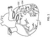
- FIG. 1illustrates a schematic view of a heart, including a coronary artery containing an occlusion.
- FIG. 2illustrates a schematic view of a coronary artery containing an occlusion and the artery's intimal, medial and adventitial wall layers.
- FIG. 3illustrates a longitudinal cross-section of a coronary artery containing an occlusion, such as a cross-section taken along line 3 - 3 of FIG. 2 .
- FIG. 4illustrates a transverse cross-section of a coronary artery containing an occlusion, such as a cross-section taken along line 4 - 4 of FIG. 2 .
- FIG. 5illustrates a schematic view, in longitudinal cross-section, of a subintimal track around an occlusion, with reentry into the natural blood vessel lumen at a location distal of the occlusion.
- FIG. 6illustrates a transverse cross-section of a coronary artery containing an occlusion and a subintimal track around the occlusion, such as a cross-section taken along line 6 - 6 of FIG. 5 .
- FIG. 7illustrates an isometric view of a portion of the distal end of a catheter device, a primary guidewire and a reentry guidewire, as constructed in accordance with at least one embodiment.
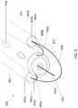
- FIG. 8illustrates an isometric side view of a portion of the distal end of a catheter device and a primary guidewire, as constructed in accordance with at least one embodiment.
- FIG. 9illustrates an isometric view of a portion of the distal end of a catheter device and a primary guidewire, as constructed in accordance with at least one embodiment.
- FIG. 10illustrates an isometric view of a portion of the distal end of a catheter device, as constructed in accordance with at least one embodiment.
- distal and proximalrefer to a position or direction relative to a user, e.g., a treating clinician. “Distal” and “distally” refer to a position that is distant, or in a direction away, from the clinician. “Proximal” and “proximally” refer to a position that is closer to, or in a direction toward, the clinician.
- patientrefers to a mammal and includes both humans and animals.
- the present disclosureprovides catheter devices, assemblies and associated methods for crossing or bypassing total or near occlusions formed in a natural vessel lumen with diminished risk of vessel wall perforation and with a minimum number of separate medical devices.
- the catheter devicecan include a central catheter flanked by two side tubes and a subintimal guidewire that forms a curved structure projecting from a distal end of the device.
- the subintimal guidewirecan facilitate entry into a subintimal space adjacent an occlusion, help orient the device within the subintimal space, and guide the device through the subintimal space, thereby forming a generally planar subintimal track.
- the central cathetercan define two reentry apertures configured as outlet passages for a reentry guidewire to exit the device, cross the intimal layer, and reenter the true lumen of the blood vessel distal to the occlusion.
- the reentry guidewirecan include an integrated micro balloon in at least some examples to increase the diameter of the reentry lumen formed through the intimal layer.
- the present devices and assembliesmay be used in various blood vessel types, e.g., coronary arteries, peripheral arteries and veins, for the treatment of coronary and peripheral vascular diseases and arterio-venous grafts, for example.
- blood vessel typese.g., coronary arteries, peripheral arteries and veins
- coronary and peripheral vascular diseases and arterio-venous graftsfor example.
- FIG. 1illustrates a schematic view of a heart 100 , including a coronary artery 102 containing an occlusion 104 .
- an “occlusion”may be a total occlusion (e.g., a CTO), near total occlusion, or partial blockage of a blood vessel.
- FIG. 2illustrates a schematic view of a coronary artery 202 containing an occlusion 204 .
- the coronary artery's wall 212includes intimal 206 , medial 208 and adventitial 210 layers. Concentrically outward of the intima 206 is the medial layer 208 . The transition between the external most portions of the intima 206 and the internal most portions of the medial 208 can be referred to as the subintimal region.
- the outermost layer of the arteryis the adventitia 210 .
- a venous wallis similar to the anatomy of an arterial wall with two primary exceptions.
- arterial wallsare thicker than venous walls to withstand higher pressures produced from heartbeats.
- an endothelium layer on an inner surface of the intima of a veinincludes one or more valves. Since blood in veins flows against gravity, the valves prevent backflow and keep blood moving toward the heart.
- the similarities between venous and arterial wall anatomiesallow the present devices, assemblies and methods to be used in a similar manner in both vessel types.
- FIGS. 3 and 4illustrate cross-sections of a coronary artery 302 , 402 containing an occlusion 304 , 404 in the form of a CTO.
- FIG. 3is a longitudinal cross-section taken along line 3 - 3 of FIG. 2 .
- FIG. 4is a transverse cross-section taken along line 4 - 4 of FIG. 2 . It is believed that the present devices and related methods can provide utility in the successful treatment of CTOs or near total blockages of blood vessels.
- FIG. 5illustrates a schematic view, in longitudinal cross-section, of a subintimal track 514 established around an occlusion 504 within a coronary artery 502 .
- the subintimal track 514can be created between the external most portions of the intimal layer 506 and the internal most portions of the medial layer 508 of the arterial wall 512 .
- the track 514can reenter the true lumen of the artery 502 at a location distal of the occlusion 504 .
- the subintimal track 514 formed using the devices, assemblies and methods described hereincan become the permanent vascular pathway around the CTO 504 , thus allowing blood to flow through the vessel despite the continued presence of the CTO.
- FIG. 6is a transverse cross-section taken along line 6 - 6 of FIG. 5 and illustrates a subintimal track 614 created around a CTO 604 within a coronary artery 602 .
- the subintimal track 614is shown between the external most portions of the intimal layer 606 and the internal most portions of the medial layer 608 .
- guidewireas used herein is to be broadly construed to include wire-like structures of dimension and length that are intended to safely navigate through or around an occlusion in a blood vessel.
- the wire-like structurescan include, but are not limited to, diagnostic, therapeutic or interventional guidewires, wire guides, spring wires, exchange guidewires and extension wires.
- Transverse dimensions of the guidewirescan primarily fall in the range of about 0.025 cm (0.010 in) to about 0.089 cm (0.035 in) in diameter and about 30 cm to about 300 cm (or more) in length.
- the guidewirescan be coated or treated with various compositions (e.g., polymers or other compounds) to change their handling or performance characteristics, such as to increase lubricity, to increase or decrease hydrophobicity, or to reduce thrombogenicity of portions of their external surface.
- a hydrophilic polymer in the form of polyvinylpyrrolidonefor example, can exhibit lubricity when moistened.
- a polymer in the form of polytetrafluoroethylene (PTFE)can reduce the coefficient of friction.
- the guidewirescan also remain uncoated and untreated.
- FIG. 7illustrates the distal end of a catheter device 700 , which is configured to create a subintimal track around a blood vessel occlusion and facilitate reentry into the true lumen of the vessel distal to the occlusion.
- the device 700includes a central catheter 702 , which can comprise an elongate, flexible material, flanked by a pair of side tubes 704 a , 704 b , each side tube defining a central lumen 706 a , 706 b .
- the device 700further includes a subintimal guidewire 708 that can extend through the side tubes 704 a , 704 b and assume a curved shape in front of the central catheter 702 , which also defines a central lumen 710 through which a primary guidewire 712 can extend. Ends of the subintimal guidewire 708 can be positioned near a proximal end of the central catheter 702 for manipulation by a user. In some uses, the ends of the subintimal guidewire 708 can be urged distally so that a size of the curved shape is wider than a collective width of the central catheter 702 and the pair of side tubes 704 a , 704 b .
- the curvature and the ability to control the size of the curvature of the subintimal guidewire 708allows the user to control the size of the subintimal delamination track—too large of a subintimal track may not allow the catheter device to be oriented properly to gain reentry to the true lumen of a vessel, and too small of a subintimal track may not allow the catheter device to be distally advanced.
- the primary guidewire 712passes through the vasculature, providing a rail that guides the device 700 to the occlusion site.
- the central catheter 702can further define a leading face 714 , which may be flat or tapered and optionally metallic.
- the body of the central catheter 702can also define a first reentry aperture 716 and a second reentry aperture 718 .
- the first reentry aperture 716may be positioned on an opposite side of the central catheter 702 relative to the second reentry aperture 718 , such that depending on the orientation of the device 700 relative to the vessel, one aperture can be positioned on the top side of the device, away from the true lumen, and the other aperture can be positioned on the bottom side of the device, toward the true lumen.
- the distal end of a reentry guidewire 720is shown visible through the first reentry aperture 716 .
- the central catheter 702 , side tubes 704 a , 704 b , and subintimal guidewire 708define an oblong, generally planar shape of the device 700 .
- This shapeis configured to cross the intimal layer of an occluded blood vessel without overextending across the medial layer.
- the device 700By advancing it through the subintimal space, the device 700 creates the subintimal track and can orient one of the two reentry apertures 716 or 718 to face the true lumen.
- a shape of the subintimal guidewire 708viewable under fluoroscopy or other imaging means, can indicate to the user whether a reentry aperture is properly oriented relative to the vessel's true lumen.
- the shape of the subintimal guidewireforms a U-shape, indicating that the guidewire extends from the first side tube along a single curve to the second side tube, proper catheter orientation may be present.
- the shape of the subintimal guidewireforms a complete loop (e.g., at least half of a FIG. 8 shape in which the guidewire crosses or encircles itself) as it extends from the first side tube to the second side tube, proper catheter orientation may not be present.
- the cross-sectional diameter x of the device 700defined by the total diameter of the central catheter 702 and both side tubes 704 a , 704 b , can be greater than the height y of the central catheter 702 .
- the central catheter 702may have a greater diameter than each of the side tubes 704 a , 704 b , which may be identical or similar in size.
- the length and/or position of the side tubes 704 a , 704 bcan vary.
- the arrangement of the side tubes 704 a , 704 b relative to the central catheter 702may be different than the arrangement shown in FIG. 7 , which depicts the side tubes 704 a , 704 b arranged symmetrically on opposite sides of the central catheter 702 .
- the side tubescan be offset from the distal end of the central catheter 702 such that the distal ends of the side tubes are not flush with the distal face 714 of the central catheter.
- the side tubesmay extend the entire length of the central catheter 702 , while in other embodiments, the side tubes may only extend for a defined length near the distal end of the device 700 .
- the length of the side tubesmay also vary depending on the length of the targeted occlusion. Longer occlusions, for example, may be treated with devices having longer side tubes.
- the central catheter and/or the side tubesmay have a length ranging from about 30 cm to about 300 cm.
- the side tubesmay have a length ranging from about 0.5 to about 1, about 2, about 5, about 10, about 15, about 20, about 25, or about 30 cm.
- the side tubesmay define metallic tip portions, which may be flat or tapered.
- portions or all of the central catheter 702 and/or side tubes 704 a , 704 bcan be doped with, made of, or otherwise include a radiopaque material.
- Radiopaque materialsare capable of producing a relatively bright image on a fluoroscopy screen or other imaging display during a medical procedure. This relatively bright image aids the user in determining its location and in some embodiments, orientation.
- Some examples of radiopaque materialscan include, but are not limited to, gold, platinum, palladium, tantalum, tungsten alloy, polymer material loaded with radiopaque filler, and the like. Additionally, other radiopaque marker bands or coils can also be incorporated into the design of the device to achieve the same or similar result.
- one or more marker bandscan be included on the device 700 to aid a user in determining the orientation of the device. As shown, one or more marker bands may be positioned on side tube 704 a or 704 b . Alternatively, marker bands may be included at different positions on both side tubes or the central catheter 702 .
- a degree of Magnetic Resonance Imaging (MRI) compatibilityis imparted into the device 700 to enhance compatibility with MRI machines.
- the central catheter 702 , the side tubes 704 a , 704 b , and/or portions thereofcan be made of a material that does not substantially distort the guidewire image or create substantial artefacts (or gaps) in the device image.
- Suitable materialscan include tungsten, cobalt-chromium-molybdenum alloys, nickel-cobalt-chromium-molybdenum allows, nitinol, and the like.
- the device 700should allow a user to steer the structure through the branches of a subject's blood vessels and manipulate it to a diseased site in an intended vessel. Additionally, the device should be sufficiently flexible to pass through sharply curved tortuous coronary anatomy, as well as to provide a sufficiently soft leading tip that will not injure vessel wall tissue during use. Further, the subintimal guidewire 712 should have sufficient column strength so that it can be pushed or otherwise urged without kinking. In some examples, the subintimal guidewire 712 may comprise nitinol. Nitinol may not kink during operation, and has a stiffness that maintains the curved or partially looped shape of the subintimal guidewire when navigating through the vasculature and pushing through the subintimal space.
- the primary guidewire 712can be advanced through a patient's vasculature toward a proximal side of an occlusion until the distal end 713 of the guidewire reaches the occlusion.
- a user manipulating the primary guidewirecan determine that it has arrived at the occlusion by feel and/or through the use of various imaging techniques, which may involve detection of the distal end of the primary guidewire.
- the device 700can be fed over the primary guidewire 712 by first inserting a proximal end of the primary guidewire into the central lumen 710 of the central catheter 702 , and then sliding the central catheter over the primary guidewire in rail-like fashion toward the occlusion.
- the primary guidewire 712can be removed from the blood vessel, leaving the distal end of the device 700 at the occlusion site.
- the distal end of the device 700can then be urged into the subintimal space adjacent to the occlusion, creating a space or track for the remainder of the device to follow.
- the curved shape and large leading radius of the guidewire 708reduces the risk of perforating the vessel wall, and upon entering the subintimal space, creates a subintimal plane through which the user can continue to advance the device 700 distally around the occlusion.
- a delamination plane between the intimal and medial layersis created around the occlusion.
- the curvature of the subintimal guidewire 708helps to minimize the possibility of penetrating the medial layer as the device is advanced distally.
- the side tubes 704 a , 704 b , the curved configuration of the subintimal guidewire 708 and the user's ability to control the length or amount of curvature of the guidewire 708help orient the device within the subintimal plane, such that the first reentry aperture 716 faces away from the true lumen of the blood vessel, and the second reentry aperture 718 faces toward the true lumen, or vice versa.
- the horizontal axis x of the device 700defines the width of the subintimal track and the vertical axis y defines the height of the subintimal track.
- the reentry guidewire 720can be advanced through the central lumen 710 .
- the reentry guidewire 720is configured to exit the central lumen 710 through the first reentry aperture 716 or the second reentry aperture 718 , but the user only extends the reentry guidewire through the reentry aperture that faces the true lumen of the vessel. In some examples, the user can make this determination based on feel.
- the tissue of the medial layeris noticeably tougher and firmer than the tissue comprising the intimal layer.
- the usermay feel more resistance when attempting to push the reentry guidewire 720 toward the medial layer compared to the intimal layer. Any noticeable resistance thus serves as an indication to the user that the reentry guidewire 720 should be passed through the other reentry aperture, toward the intimal layer and into the true lumen.
- the reentry guidewire 720After exiting the central lumen 710 through the correct aperture, the reentry guidewire 720 passes through the intimal wall and back into the true lumen, thus creating a reentry lumen through the intimal wall and completing the subintimal track pathway from a proximal side to a distal side of the occlusion.
- the diameter of the reentry guidewire 720can determine the diameter of the reentry lumen. To eliminate the need for the user to move the reentry guidewire in a circular, back-and-forth, or whiplash like motion in an attempt to increase the diameter of the reentry lumen, the reentry guidewire can have a larger diameter than other guidewires or catheters used for luminal reentry in existing devices.
- the reentry guidewirecan include an integrated micro balloon.
- the diameter of the micro balloonmay vary depending on the intended diameter of the reentry lumen formed in the vessel wall. In some examples, the diameter of the micro balloon may range from about 1 to about 15 mm, about 1 to about 10 mm, or about 1 to about 5 mm.
- treatment methodsmay further involve removing the catheter device 700 from the blood vessel, optionally swapping the reentry guidewire 720 for a primary guidewire, and advancing the distal end of a catheter or other treatment device over the reentry guidewire 720 or the primary guidewire to a location near the distal side of the occlusion.
- the catheter or other treatment devicecan be guided around the occlusion using the reentry guidewire 720 or the primary guidewire as a rail and subsequently used to perform balloon angioplasty, stenting, atherectomy, or another endovascular treatment method for compressing and opening the occlusion region via the subintimal track.
- FIG. 8illustrates an isometric side view of a portion of the distal end of another catheter device 800 configured to form a subintimal track around an occlusion.
- the device 800includes a central catheter 802 defining a central lumen 810 flanked by a pair of side tubes (only side tube 804 b is visible from this viewing angle).
- a primary guidewire 812extends through the central lumen 810 .
- the side tubescan be offset relative to the distal end of the central catheter 802 and, as further shown, can have a length that spans only portion of the length of the central catheter.
- the side tubese.g., side tube 804 b
- a lateral subintimal guidewire 805 bcan be attached to the side tube 804 b at a proximal attachment point 807 b
- a second end of the lateral subintimal guidewire 805 bcan be attached to a tapered surface 811 , which may be metallic, of the central catheter 802 at a distal attachment point 809 b .
- the lateral subintimal guidewire 805 bcan be configured to have a curved, partially looped shape.
- the configuration of the device 800is identical on both sides, such that first and second lateral subintimal guidewires 805 a , 805 b are included.
- the lateral subintimal guidewires and/or central cathetercan function similarly to the subintimal guidewire 708 of FIG.
- the lateral subintimal guidewiresextend distally can vary.
- the most distal point of the guidewiresmay be flush with the most distal point of the central catheter.
- the guidewiresmay extend distally beyond the most distal point of the central catheter.
- the lateral subintimal guidewiresmay protrude laterally away from the external wall of the central catheter.
- FIG. 9illustrates an isometric view of a portion of the distal end of another catheter device 900 configured to form a subintimal track around an occlusion.
- the device 900includes a central catheter 902 flanked by a pair of rod-like side tubes 904 a , 904 b , each defining a distal face 906 a , 906 b instead of a central lumen.
- a primary guidewire 912can extend through a central lumen of the central catheter 902 .
- the body of the central catheter 902can also define a first reentry aperture 916 and a second reentry aperture 918 .
- the device 900also includes a pair of lateral subintimal guidewires 905 a , 905 b extending respectively from proximal attachment points 907 a , 907 b on the distal faces 906 a , 906 b of the side tubes 904 a , 904 b to distal attachment points 909 a , 909 b on a tapered surface 911 of the central catheter.
- a longer subintimal guidewire 908may also be included, forming a curved structure around the distal end of the central catheter.
- the device 900can function similar to the devices 700 , 800 , described above.
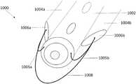
- FIG. 10illustrates an isometric view of a portion of the distal end of another catheter device 1000 configured to form a subintimal track around an occlusion.
- the device 1000includes a central catheter 1002 and a pair of side tubes 1004 a , 1004 b .
- the device 1000can further include lateral subintimal guidewires 1005 a , 1005 b and a longer subintimal guidewire 1008 .
- the side tubes 1004 a , 1004 bcan define various shapes.
- the side tubes 1004 a , 1004 bdefine slanted distal surfaces 1006 a , 1006 b to facilitate smooth passage through the intimal layer and subintimal space.
- the side tubesare portrayed herein as being generally cylindrical, the side tubes can also or instead by any suitable or desired shape, including fin-shaped, triangular, wedge, rectangular, etc.
- the device 1000can function similar to the devices 700 , 800 , 900 , described above.
- Cardiovascular diseaseincluding atherosclerosis, is a leading cause of death in the United States and elsewhere.
- a method for treating atherosclerosis and other forms of vessel lumen narrowingis angioplasty.
- the objective of angioplastyis to restore adequate blood flow through the affected vessel.
- the present devices, assemblies and related methodsallow for treating an occlusion, particularly a CTO, using a reduced number of separate medical devices, while minimizing the likelihood of vessel wall dissection and increasing the diameter of a reentry pathway distal to the occlusion.
- a catheter devicecan include a central catheter defining: a central lumen extending from a proximal end of the central catheter to a distal end of the central catheter, the central lumen configured to receive a primary guidewire; and at least one reentry aperture oriented transverse to the extension of the central lumen.
- the catheter devicecan further include a first side tube and a second side tube both coupled with the central catheter and extending along a longitudinal axis thereof.
- the first side tubecan flank an opposite side of the central catheter relative to the second side tube.
- a subintimal guidewirecan extend from the first side tube, distally beyond the distal end of the central catheter, to the second side tube.
- Example 2the catheter device of Example 1 can optionally be configured such that ends of the subintimal guidewire extend to a position near the proximal end of the central catheter and are configured to receive and translate an externally-applied pushing or pulling force.
- Example 3the catheter device of any one of Examples 1 or 2 can optionally be configured such that the first side tube and the second side tube comprise rods, and ends of the subintimal guidewire can be attached to a distal face of the first side tube and a distal face of the second side tube.
- Example 4the catheter device of any one of Examples 1-3 can optionally be configured such that the central catheter has a larger diameter than a diameter of the first side tube and a diameter of the second side tube.
- Example 5the catheter device of Example 4 can optionally be configured such that a combined width of the central catheter, the first side tube and the second side tube is greater than a height of the central catheter.
- Example 6the catheter device of Example 4 can optionally be configured such that the first side tube and the second side tube are equally sized.
- Example 7the catheter device of any one or any combination of Examples 1-6 can optionally further comprise a radiopaque marker.
- Example 8the catheter device of any one or any combination of Examples 1-7 can optionally be configured such that a distal end of the central catheter is flush with a distal end of the first side tube and a distal end of the second side tube.
- Example 9the catheter device of any one or any combination of Examples 1-7 can optionally be configured such that the distal end of the central catheter extends distally beyond a distal end of the first side tube and a distal end of the second side tube.
- Example 10the catheter device of any one or any combination of Examples 1-9 can optionally be configured such that the distal end of the central catheter defines a tapered tip portion.
- Example 11the catheter device of any one or any combination of Examples 1-10 can optionally be configured such that the subintimal guidewire defines a partial loop that extends distally beyond the distal end of the central catheter.
- Example 12a method for using a catheter device according to any one or any combination of Examples 1-11 to bypass an occlusion in a blood vessel comprising a blood vessel wall defining a true lumen can involve advancing a primary guidewire through the true lumen toward a proximal side of the occlusion; loading the central catheter of the catheter device onto a proximal portion of the primary guidewire; advancing the catheter device over the primary guidewire toward the proximal side of the occlusion; upon reaching the proximal side of the occlusion, advancing the catheter device into a subintimal space within the blood vessel wall; urging the catheter device through the subintimal space until a distal end of the catheter device is positioned such that the first reentry aperture and the second reentry aperture are distal to the occlusion; advancing a reentry guidewire through the central lumen of the central catheter and out of a reentry aperture toward the true lumen distal to the occlusion; and
- Example 13the method of Example 12 can optionally be configured such that the reentry guidewire includes an integrated micro balloon.
- Example 14the method of Example 13 can optionally be configured such that the micro balloon has a diameter of about 1 mm to about 5 mm.
- Example 15the method of any one or any combination of Examples 12-14 can optionally further involve removing the primary guidewire from the true lumen when the catheter device arrives at the proximal side of the occlusion.
- Example 16the method of any one or any combination of Examples 12-15 can optionally be configured to be employed where the occlusion is a chronic total occlusion.
Landscapes
- Health & Medical Sciences (AREA)
- Life Sciences & Earth Sciences (AREA)
- Surgery (AREA)
- Animal Behavior & Ethology (AREA)
- Engineering & Computer Science (AREA)
- Biomedical Technology (AREA)
- Heart & Thoracic Surgery (AREA)
- General Health & Medical Sciences (AREA)
- Public Health (AREA)
- Veterinary Medicine (AREA)
- Medical Informatics (AREA)
- Molecular Biology (AREA)
- Nuclear Medicine, Radiotherapy & Molecular Imaging (AREA)
- Anesthesiology (AREA)
- Hematology (AREA)
- Pulmonology (AREA)
- Biophysics (AREA)
- Oral & Maxillofacial Surgery (AREA)
- Pathology (AREA)
- Orthopedic Medicine & Surgery (AREA)
- Vascular Medicine (AREA)
- Media Introduction/Drainage Providing Device (AREA)
Abstract
Description
Claims (22)
Priority Applications (1)
| Application Number | Priority Date | Filing Date | Title |
|---|---|---|---|
| US16/160,162US10722252B2 (en) | 2017-10-26 | 2018-10-15 | Subintimal catheter device, assembly and related methods |
Applications Claiming Priority (2)
| Application Number | Priority Date | Filing Date | Title |
|---|---|---|---|
| US201762577283P | 2017-10-26 | 2017-10-26 | |
| US16/160,162US10722252B2 (en) | 2017-10-26 | 2018-10-15 | Subintimal catheter device, assembly and related methods |
Publications (2)
| Publication Number | Publication Date |
|---|---|
| US20190125373A1 US20190125373A1 (en) | 2019-05-02 |
| US10722252B2true US10722252B2 (en) | 2020-07-28 |
Family
ID=64110126
Family Applications (1)
| Application Number | Title | Priority Date | Filing Date |
|---|---|---|---|
| US16/160,162Active2039-04-19US10722252B2 (en) | 2017-10-26 | 2018-10-15 | Subintimal catheter device, assembly and related methods |
Country Status (3)
| Country | Link |
|---|---|
| US (1) | US10722252B2 (en) |
| EP (1) | EP3700615B1 (en) |
| WO (1) | WO2019083757A1 (en) |
Cited By (1)
| Publication number | Priority date | Publication date | Assignee | Title |
|---|---|---|---|---|
| US11369392B2 (en) | 2019-04-05 | 2022-06-28 | Traverse Vascular, Inc. | Intravascular catheter with fluoroscopically visible indicium of rotational orientation |
Families Citing this family (1)
| Publication number | Priority date | Publication date | Assignee | Title |
|---|---|---|---|---|
| CA3220367A1 (en)* | 2021-05-27 | 2022-12-01 | Jonathan Karl Burkholz | Intravenous catheter device having a guidewire for actively repositioning a catheter tip |
Citations (104)
| Publication number | Priority date | Publication date | Assignee | Title |
|---|---|---|---|---|
| US3452742A (en) | 1966-05-31 | 1969-07-01 | Us Catheter & Instr Corp | Controlled vascular curvable spring guide |
| US4846186A (en) | 1988-01-12 | 1989-07-11 | Cordis Corporation | Flexible guidewire |
| EP0468645A1 (en) | 1990-07-25 | 1992-01-29 | C.R. Bard, Inc. | Movable core guidewire |
| EP0495299A1 (en) | 1990-12-03 | 1992-07-22 | C.R. Bard, Inc. | Guidewire tip construction |
| US5303714A (en) | 1990-11-09 | 1994-04-19 | Boston Scientific Corporation | Guidewire for crossing occlusions in blood vessels |
| US5505699A (en) | 1994-03-24 | 1996-04-09 | Schneider (Usa) Inc. | Angioplasty device |
| WO1998005376A1 (en) | 1996-08-06 | 1998-02-12 | Cook Incorporated | Retrograde-antegrade catheterization guide wire |
| US5728122A (en) | 1994-01-18 | 1998-03-17 | Datascope Investment Corp. | Guide wire with releaseable barb anchor |
| US5938623A (en) | 1994-10-28 | 1999-08-17 | Intella Interventional Systems | Guide wire with adjustable stiffness |
| EP0778042B1 (en) | 1995-12-04 | 2000-03-01 | Target Therapeutics, Inc. | Nickel-titanium, lubricious medical catheter wire |
| US6211049B1 (en) | 1998-09-10 | 2001-04-03 | Micron Technology, Inc. | Forming submicron integrated-circuit wiring from gold, silver, copper, and other metals |
| US6217527B1 (en) | 1998-09-30 | 2001-04-17 | Lumend, Inc. | Methods and apparatus for crossing vascular occlusions |
| USRE37148E1 (en) | 1990-06-04 | 2001-04-24 | Medtronic Ave, Inc. | Guidewire tip construction |
| US6231546B1 (en) | 1998-01-13 | 2001-05-15 | Lumend, Inc. | Methods and apparatus for crossing total occlusions in blood vessels |
| US6254550B1 (en) | 1998-08-19 | 2001-07-03 | Cook Incorporated | Preformed wire guide |
| US20020082523A1 (en) | 2000-12-21 | 2002-06-27 | Bryan Kinsella | Steerable guidewire |
| US6464650B2 (en) | 1998-12-31 | 2002-10-15 | Advanced Cardiovascular Systems, Inc. | Guidewire with smoothly tapered segment |
| WO2002096492A2 (en) | 2001-05-30 | 2002-12-05 | Boston Scientific Limited | Distal tip portion for a guide wire |
| US6638266B2 (en) | 2000-12-21 | 2003-10-28 | Advanced Cardiovascular Systems, Inc. | Guidewire with an intermediate variable stiffness section |
| WO2004018031A2 (en) | 2002-08-22 | 2004-03-04 | William A. Cook Australia Pty. Ltd. | Guide wire |
| US6761696B1 (en) | 2001-11-13 | 2004-07-13 | Advanced Cardiovascular Systems, Inc. | Guide wire with a non-rectangular shaping member |
| US20040193151A1 (en) | 2001-06-06 | 2004-09-30 | Oratec Interventions, Inc. | Intervertebral disc device employing looped probe |
| US20040199088A1 (en) | 2003-04-03 | 2004-10-07 | Bakos Gregory J. | Guide wire having bending segment |
| US7004173B2 (en) | 2000-12-05 | 2006-02-28 | Lumend, Inc. | Catheter system for vascular re-entry from a sub-intimal space |
| WO2006039217A1 (en) | 2004-09-30 | 2006-04-13 | Wilson-Cook Medical Inc. | Loop tip wire guide |
| US7128718B2 (en) | 2002-03-22 | 2006-10-31 | Cordis Corporation | Guidewire with deflectable tip |
| US20070219464A1 (en) | 2002-03-22 | 2007-09-20 | Stephen Davis | Guidewire with deflectable re-entry tip |
| WO2007121002A1 (en) | 2006-04-12 | 2007-10-25 | Medtronic Vascular, Inc. | Medical guidewire tip construction |
| US7294139B1 (en)* | 2002-07-26 | 2007-11-13 | C.M. Wright, Inc. | Controlled - motion endoscopic grasping instrument |
| US20080064988A1 (en) | 2006-09-07 | 2008-03-13 | Wilson-Cook Medical Inc. | Loop Tip Wire Guide |
| US20080228171A1 (en) | 2006-11-21 | 2008-09-18 | Kugler Chad J | Endovascular devices and methods for exploiting intramural space |
| US20080269641A1 (en) | 2007-04-25 | 2008-10-30 | Medtronic Vascular, Inc. | Method of using a guidewire with stiffened distal section |
| US7520863B2 (en) | 2002-03-22 | 2009-04-21 | Cordis Corporation | Guidewire with deflectable tip having improved torque characteristics |
| EP1419794B1 (en) | 2001-07-27 | 2009-11-11 | JMS Co., Ltd. | Blood dialyzer |
| WO2010087953A1 (en) | 2009-01-27 | 2010-08-05 | Device Source, Llc | Guidewire |
| WO2010092347A1 (en) | 2009-02-12 | 2010-08-19 | St. Georges Healthcare Nhs Trust | Percutaneous guidewire |
| US7785273B2 (en) | 2003-09-22 | 2010-08-31 | Boston Scientific Scimed, Inc. | Guidewire with reinforcing member |
| US7785274B2 (en) | 2003-12-18 | 2010-08-31 | Terumo Kabushiki Kaisha | Guide wire |
| US20100228151A1 (en) | 2007-03-07 | 2010-09-09 | Eyoca Medical Ltd. | Multi-stiffness guidewire |
| US20110098648A1 (en) | 2009-10-27 | 2011-04-28 | Tomihisa Kato | Medical guide wire, a method of making the same, an assembly of microcatheter and guiding catheter combined with the medical guide wire |
| US7938819B2 (en) | 2005-09-12 | 2011-05-10 | Bridgepoint Medical, Inc. | Endovascular devices and methods |
| US7942832B2 (en) | 2004-11-01 | 2011-05-17 | Terumo Kabushiki Kaisha | Medical guide wire |
| WO2010115163A9 (en) | 2009-04-03 | 2011-07-28 | Scientia Vascular, Llc | Micro-fabricated catheter and guidewire devices |
| US8022331B2 (en) | 2003-02-26 | 2011-09-20 | Boston Scientific Scimed, Inc. | Method of making elongated medical devices |
| US8083727B2 (en) | 2005-09-12 | 2011-12-27 | Bridgepoint Medical, Inc. | Endovascular devices and methods for exploiting intramural space |
| US20120095485A1 (en) | 2010-10-18 | 2012-04-19 | Cully Edward H | Systems and methods for percutaneous occlusion crossing |
| US20120123329A1 (en) | 2010-06-30 | 2012-05-17 | Tomihisa Kato | medical guide wire, an assembly of microcatheter and guiding catheter combined with the medical guide wire, and an assembly of ballooncatheter and guiding catheter combined with the medical guide wire |
| US8202246B2 (en) | 2008-02-05 | 2012-06-19 | Bridgepoint Medical, Inc. | Crossing occlusions in blood vessels |
| US20120158021A1 (en) | 2010-12-19 | 2012-06-21 | Mitralign, Inc. | Steerable guide catheter having preformed curved shape |
| US8226566B2 (en) | 2009-06-12 | 2012-07-24 | Flowcardia, Inc. | Device and method for vascular re-entry |
| US8241311B2 (en) | 2009-12-15 | 2012-08-14 | Medtronic Vascular, Inc. | Methods and systems for bypassing an occlusion in a blood vessel |
| US8252015B2 (en) | 2003-10-03 | 2012-08-28 | Medtronic, Inc. | Expandable guide sheath and apparatus and methods for making them |
| US8257278B2 (en) | 2002-05-14 | 2012-09-04 | Advanced Cardiovascular Systems, Inc. | Metal composite guide wire |
| US8257383B2 (en) | 2007-03-29 | 2012-09-04 | Boston Scientific Limited | Lumen reentry devices and methods |
| US20120239073A1 (en) | 2007-12-20 | 2012-09-20 | Ureca B.V. | Catheter assembly |
| US8323261B2 (en) | 2005-09-12 | 2012-12-04 | Bridgepoint Medical, Inc. | Methods of accessing an intramural space |
| US8337425B2 (en) | 2008-02-05 | 2012-12-25 | Bridgepoint Medical, Inc. | Endovascular device with a tissue piercing distal probe and associated methods |
| US8374680B2 (en) | 2008-04-21 | 2013-02-12 | Medtronic Vascular, Inc. | Needleless catheters and methods for true lumen re-entry in treatment of chronic total occlusions and other disorders |
| US8376961B2 (en) | 2008-04-07 | 2013-02-19 | Boston Scientific Scimed, Inc. | Micromachined composite guidewire structure with anisotropic bending properties |
| US20130046286A1 (en) | 2011-08-17 | 2013-02-21 | Abbott Cardiovascular Systems | Narrow hysteresis ni-ti core wire for enhanced guide wire steering response |
| US20130238003A1 (en) | 2012-03-07 | 2013-09-12 | Frank Fischer | Lumen re-entry system and method |
| US20130245430A1 (en) | 1998-01-13 | 2013-09-19 | Lumend, Inc. | Catheter systems for crossing total occlusions in vasculature |
| US8551020B2 (en) | 2006-09-13 | 2013-10-08 | Boston Scientific Scimed, Inc. | Crossing guidewire |
| US20130317534A1 (en) | 2012-05-24 | 2013-11-28 | Boston Scientific Scimed, Inc. | Subintimal re-entry catheter with an expandable structure |
| US20140276911A1 (en)* | 2013-03-15 | 2014-09-18 | Boston Scientific Scimed, Inc. | Tissue resection snares |
| US20140275983A1 (en) | 2013-03-13 | 2014-09-18 | Invatec S.P.A. | Side Lumen Reentry Catheters And Related Methods |
| US20140277068A1 (en) | 2013-03-14 | 2014-09-18 | Boston Scientific Scimed, Inc. | Systems, apparatus and methods for treating blood vessels |
| US20140277053A1 (en) | 2013-03-14 | 2014-09-18 | Boston Scientific Scimed, Inc. | Subintimal re-entry catheter with shape controlled balloon |
| US20140371718A1 (en) | 2011-06-30 | 2014-12-18 | The Spectranetics Corporation | Reentry cathether and method thereof |
| US8920449B2 (en) | 2011-06-29 | 2014-12-30 | Cordis Corporation | System and method for re-entering a vessel lumen |
| EP2700368B1 (en) | 2011-04-27 | 2015-02-11 | Rex Medical, L.P. | Rotational thrombectomy wire |
| US8956376B2 (en) | 2011-06-30 | 2015-02-17 | The Spectranetics Corporation | Reentry catheter and method thereof |
| US20150051633A1 (en) | 2013-08-15 | 2015-02-19 | Invatec S.P.A. | Catheter Systems With a Blocking Mechanism and Methods for Bypassing an Occlusion in a Blood Vessel |
| US8998936B2 (en) | 2011-06-30 | 2015-04-07 | The Spectranetics Corporation | Reentry catheter and method thereof |
| US20150148706A1 (en) | 2013-11-26 | 2015-05-28 | Boston Scientific Scimed, Inc. | Medical devices for accessing body lumens |
| US9060802B2 (en) | 2006-11-21 | 2015-06-23 | Bridgepoint Medical, Inc. | Endovascular devices and methods for exploiting intramural space |
| US9174032B2 (en) | 2012-07-13 | 2015-11-03 | Boston Scientific Scimed, Inc. | Subintimal reentry system |
| US20150320975A1 (en) | 2012-09-06 | 2015-11-12 | Avinger, Inc. | Re-entry stylet for catheter |
| US20160008015A1 (en)* | 2014-07-09 | 2016-01-14 | Boston Scientific Scimed, Inc. | Medical retrieval devices and methods |
| US20160008584A1 (en) | 2014-07-08 | 2016-01-14 | Vascular Solutions, Inc. | Guidewires and Methods for Percutaneous Occlusion Crossing |
| US20160045713A1 (en) | 2009-08-28 | 2016-02-18 | Boston Scientific Limited | Inverted balloon neck on catheter |
| US9278192B2 (en) | 2013-02-12 | 2016-03-08 | Invatec S.P.A. | Re-entry catheters and related methods |
| US20160074627A1 (en) | 2014-09-15 | 2016-03-17 | Orbusneich Medical, Inc. | Vascular Re-entry Catheter |
| US20160081709A1 (en) | 2014-09-23 | 2016-03-24 | Cordis Corporation | Catheter systems and methods for re-entry in body vessels with chronic total occlusion |
| US9301774B2 (en) | 2013-01-07 | 2016-04-05 | Cook Medical Technologies Llc | Lumen reentry mechanism and method |
| US20160157872A1 (en) | 2012-11-21 | 2016-06-09 | Cook Medical Technologies Llc | Lumen Re-Entry System And Method |
| US20160192952A1 (en) | 2012-09-10 | 2016-07-07 | Cook Medical Technologies Llc | Reentry device |
| US20160206334A1 (en) | 2013-08-27 | 2016-07-21 | Reflow Medical, Inc. | Shapeable re-entry devices and associated systems and methods |
| US9402981B2 (en) | 2011-09-19 | 2016-08-02 | Boston Scientific Scimed, Inc. | Subintimal re-entry catheter and retrograde recanalization |
| US20160242795A1 (en)* | 2013-11-12 | 2016-08-25 | Olympus Corporation | Basket type grasping forceps |
| US20160271374A1 (en) | 2015-03-19 | 2016-09-22 | Boston Scientific Scimed, Inc. | Subintimal re-entry balloon catheter |
| US9451984B2 (en) | 2013-01-15 | 2016-09-27 | Boston Scientific Scimed, Inc. | Subintimal re-entry catheter with actuatable orientation mechanism |
| US20160287273A1 (en)* | 2015-03-31 | 2016-10-06 | Terumo Kabushiki Kaisha | Method for removing calculus from an access sheath |
| US20160317175A1 (en) | 2012-01-24 | 2016-11-03 | Ureca B.V. | Surgical cutting instrument |
| US9486239B2 (en) | 2012-05-24 | 2016-11-08 | Boston Scientific Scimed, Inc. | Subintimal re-entry device |
| US20160346002A1 (en)* | 2015-05-27 | 2016-12-01 | Angioworks Medical, B.V. | Devices and methods for minimally invasive tissue removal |
| US20170049472A1 (en)* | 2014-04-30 | 2017-02-23 | Coloplast A/S | Snare instrument with a distal snare structure |
| US20170079671A1 (en) | 2015-09-22 | 2017-03-23 | Medtronic Vascular, Inc. | Occlusion Bypassing Apparatus With a Re-Entry Needle and a Stabilization Tube |
| US9603615B2 (en) | 2012-01-18 | 2017-03-28 | C.R. Bard, Inc. | Vascular re-entry device |
| US20170100141A1 (en) | 2015-10-07 | 2017-04-13 | Medtronic Vascular, Inc. | Occlusion Bypassing Apparatus With A Re-Entry Needle and a Distal Stabilization Balloon |
| US20170172653A1 (en) | 2014-01-29 | 2017-06-22 | Baylis Medical Company Inc. | Side-port Catheter |
| US20180049759A1 (en)* | 2015-03-26 | 2018-02-22 | Jeffrey E. Thomas | Stroke Catheter for Use in Revascularization Procedures and Method of Using Same |
| US20180256179A1 (en)* | 2017-03-07 | 2018-09-13 | Terumo Kabushiki Kaisha | Medical device, medical system, and treatment method |
| US20180325538A1 (en)* | 2017-05-12 | 2018-11-15 | Ellenial Surgical, LLC | Fecalith removal system |
- 2018
- 2018-10-15EPEP18797326.8Apatent/EP3700615B1/enactiveActive
- 2018-10-15WOPCT/US2018/055832patent/WO2019083757A1/ennot_activeCeased
- 2018-10-15USUS16/160,162patent/US10722252B2/enactiveActive
Patent Citations (150)
| Publication number | Priority date | Publication date | Assignee | Title |
|---|---|---|---|---|
| US3452742A (en) | 1966-05-31 | 1969-07-01 | Us Catheter & Instr Corp | Controlled vascular curvable spring guide |
| US4846186A (en) | 1988-01-12 | 1989-07-11 | Cordis Corporation | Flexible guidewire |
| USRE37148E1 (en) | 1990-06-04 | 2001-04-24 | Medtronic Ave, Inc. | Guidewire tip construction |
| EP0468645A1 (en) | 1990-07-25 | 1992-01-29 | C.R. Bard, Inc. | Movable core guidewire |
| US5303714A (en) | 1990-11-09 | 1994-04-19 | Boston Scientific Corporation | Guidewire for crossing occlusions in blood vessels |
| US5385152A (en) | 1990-11-09 | 1995-01-31 | Boston Scientific Corporation | Guidewire for crossing occlusions in blood vessels |
| EP0495299A1 (en) | 1990-12-03 | 1992-07-22 | C.R. Bard, Inc. | Guidewire tip construction |
| US5728122A (en) | 1994-01-18 | 1998-03-17 | Datascope Investment Corp. | Guide wire with releaseable barb anchor |
| US5505699A (en) | 1994-03-24 | 1996-04-09 | Schneider (Usa) Inc. | Angioplasty device |
| US5938623A (en) | 1994-10-28 | 1999-08-17 | Intella Interventional Systems | Guide wire with adjustable stiffness |
| EP0778042B1 (en) | 1995-12-04 | 2000-03-01 | Target Therapeutics, Inc. | Nickel-titanium, lubricious medical catheter wire |
| WO1998005376A1 (en) | 1996-08-06 | 1998-02-12 | Cook Incorporated | Retrograde-antegrade catheterization guide wire |
| US6231546B1 (en) | 1998-01-13 | 2001-05-15 | Lumend, Inc. | Methods and apparatus for crossing total occlusions in blood vessels |
| US6511458B2 (en) | 1998-01-13 | 2003-01-28 | Lumend, Inc. | Vascular re-entry catheter |
| US20130245430A1 (en) | 1998-01-13 | 2013-09-19 | Lumend, Inc. | Catheter systems for crossing total occlusions in vasculature |
| US6235000B1 (en) | 1998-01-13 | 2001-05-22 | Lumend, Inc. | Apparatus for crossing total occlusion in blood vessels |
| US6719725B2 (en) | 1998-01-13 | 2004-04-13 | Lumend, Inc. | Re-entry catheter |
| US6514217B1 (en) | 1998-01-13 | 2003-02-04 | Lumend, Inc. | Methods and apparatus for treating vascular occlusions |
| US6254550B1 (en) | 1998-08-19 | 2001-07-03 | Cook Incorporated | Preformed wire guide |
| US6211049B1 (en) | 1998-09-10 | 2001-04-03 | Micron Technology, Inc. | Forming submicron integrated-circuit wiring from gold, silver, copper, and other metals |
| US6217527B1 (en) | 1998-09-30 | 2001-04-17 | Lumend, Inc. | Methods and apparatus for crossing vascular occlusions |
| US6464650B2 (en) | 1998-12-31 | 2002-10-15 | Advanced Cardiovascular Systems, Inc. | Guidewire with smoothly tapered segment |
| US7004173B2 (en) | 2000-12-05 | 2006-02-28 | Lumend, Inc. | Catheter system for vascular re-entry from a sub-intimal space |
| US6500130B2 (en) | 2000-12-21 | 2002-12-31 | Scimed Life Systems, Inc. | Steerable guidewire |
| US20020082523A1 (en) | 2000-12-21 | 2002-06-27 | Bryan Kinsella | Steerable guidewire |
| US6638266B2 (en) | 2000-12-21 | 2003-10-28 | Advanced Cardiovascular Systems, Inc. | Guidewire with an intermediate variable stiffness section |
| WO2002096492A2 (en) | 2001-05-30 | 2002-12-05 | Boston Scientific Limited | Distal tip portion for a guide wire |
| US20020183654A1 (en) | 2001-05-30 | 2002-12-05 | Scimed Life Systems, Inc. | Distal tip portion for a guide wire |
| US20040193151A1 (en) | 2001-06-06 | 2004-09-30 | Oratec Interventions, Inc. | Intervertebral disc device employing looped probe |
| EP1419794B1 (en) | 2001-07-27 | 2009-11-11 | JMS Co., Ltd. | Blood dialyzer |
| US6761696B1 (en) | 2001-11-13 | 2004-07-13 | Advanced Cardiovascular Systems, Inc. | Guide wire with a non-rectangular shaping member |
| US7128718B2 (en) | 2002-03-22 | 2006-10-31 | Cordis Corporation | Guidewire with deflectable tip |
| US20070219464A1 (en) | 2002-03-22 | 2007-09-20 | Stephen Davis | Guidewire with deflectable re-entry tip |
| US7520863B2 (en) | 2002-03-22 | 2009-04-21 | Cordis Corporation | Guidewire with deflectable tip having improved torque characteristics |
| US8257278B2 (en) | 2002-05-14 | 2012-09-04 | Advanced Cardiovascular Systems, Inc. | Metal composite guide wire |
| US7294139B1 (en)* | 2002-07-26 | 2007-11-13 | C.M. Wright, Inc. | Controlled - motion endoscopic grasping instrument |
| US7715903B2 (en) | 2002-08-22 | 2010-05-11 | Cook Incorporated | Guide wire |
| US20040073141A1 (en) | 2002-08-22 | 2004-04-15 | William A. Cook Australia Pty. Ltd. | Guide wire |
| WO2004018031A2 (en) | 2002-08-22 | 2004-03-04 | William A. Cook Australia Pty. Ltd. | Guide wire |
| US8022331B2 (en) | 2003-02-26 | 2011-09-20 | Boston Scientific Scimed, Inc. | Method of making elongated medical devices |
| US20040199088A1 (en) | 2003-04-03 | 2004-10-07 | Bakos Gregory J. | Guide wire having bending segment |
| US20080004606A1 (en) | 2003-04-03 | 2008-01-03 | Swain Paul C | Guide wire structure for insertion into an internal space |
| US7785273B2 (en) | 2003-09-22 | 2010-08-31 | Boston Scientific Scimed, Inc. | Guidewire with reinforcing member |
| US8252015B2 (en) | 2003-10-03 | 2012-08-28 | Medtronic, Inc. | Expandable guide sheath and apparatus and methods for making them |
| US8313445B2 (en) | 2003-12-18 | 2012-11-20 | Terumo Kabushiki Kaisha | Guide wire |
| US7785274B2 (en) | 2003-12-18 | 2010-08-31 | Terumo Kabushiki Kaisha | Guide wire |
| WO2006039217A1 (en) | 2004-09-30 | 2006-04-13 | Wilson-Cook Medical Inc. | Loop tip wire guide |
| US7942832B2 (en) | 2004-11-01 | 2011-05-17 | Terumo Kabushiki Kaisha | Medical guide wire |
| US20140121689A1 (en) | 2005-09-12 | 2014-05-01 | Bridgepoint Medical, Inc. | Endovascular devices and methods |
| US20160183953A1 (en) | 2005-09-12 | 2016-06-30 | Bridgepoint Medical, Inc. | Endovascular devices and methods for exploiting intramural space |
| US7938819B2 (en) | 2005-09-12 | 2011-05-10 | Bridgepoint Medical, Inc. | Endovascular devices and methods |
| US20180000513A1 (en) | 2005-09-12 | 2018-01-04 | Bridgepoint Medical, Inc. | Endovascular devices and methods for exploiting intramural space |
| US9308019B2 (en) | 2005-09-12 | 2016-04-12 | Bridgepoint Medical, Inc. | Endovascular devices and methods for exploiting intramural space |
| US8323261B2 (en) | 2005-09-12 | 2012-12-04 | Bridgepoint Medical, Inc. | Methods of accessing an intramural space |
| US20110276079A1 (en) | 2005-09-12 | 2011-11-10 | Bridgepoint Medical, Inc. | Endovascular devices and methods |
| US8083727B2 (en) | 2005-09-12 | 2011-12-27 | Bridgepoint Medical, Inc. | Endovascular devices and methods for exploiting intramural space |
| US20150080928A1 (en) | 2005-09-12 | 2015-03-19 | Bridgepoint Medical, Inc. | Endovascular devices and methods for exploiting intramural space |
| US8512310B2 (en) | 2005-09-12 | 2013-08-20 | Bridgepoint Medical, Inc. | Endovascular devices and methods for exploiting intramural space |
| US8961494B2 (en) | 2005-09-12 | 2015-02-24 | Bridgepoint Medical, Inc. | Endovascular devices and methods for exploiting intramural space |
| WO2007121002A1 (en) | 2006-04-12 | 2007-10-25 | Medtronic Vascular, Inc. | Medical guidewire tip construction |
| US20080064988A1 (en) | 2006-09-07 | 2008-03-13 | Wilson-Cook Medical Inc. | Loop Tip Wire Guide |
| US8551020B2 (en) | 2006-09-13 | 2013-10-08 | Boston Scientific Scimed, Inc. | Crossing guidewire |
| US20080228171A1 (en) | 2006-11-21 | 2008-09-18 | Kugler Chad J | Endovascular devices and methods for exploiting intramural space |
| US9060802B2 (en) | 2006-11-21 | 2015-06-23 | Bridgepoint Medical, Inc. | Endovascular devices and methods for exploiting intramural space |
| US9717889B2 (en) | 2006-11-21 | 2017-08-01 | Bridgepoint Medical, Inc. | Endovascular devices and methods for exploiting intramural space |
| US8277469B2 (en) | 2007-03-07 | 2012-10-02 | Eyoca Medical Ltd. | Multi-stiffness guidewire |
| US20100228151A1 (en) | 2007-03-07 | 2010-09-09 | Eyoca Medical Ltd. | Multi-stiffness guidewire |
| US8257383B2 (en) | 2007-03-29 | 2012-09-04 | Boston Scientific Limited | Lumen reentry devices and methods |
| US8257382B2 (en) | 2007-03-29 | 2012-09-04 | Boston Scientific Limited | Lumen reentry devices and methods |
| US8721675B2 (en) | 2007-03-29 | 2014-05-13 | Boston Scientific Limited | Lumen reentry devices and methods |
| US20080269641A1 (en) | 2007-04-25 | 2008-10-30 | Medtronic Vascular, Inc. | Method of using a guidewire with stiffened distal section |
| US20120239073A1 (en) | 2007-12-20 | 2012-09-20 | Ureca B.V. | Catheter assembly |
| US20120323251A1 (en) | 2008-02-05 | 2012-12-20 | Bridgepoint Medical, Inc. | Crossing occlusions in blood vessels |
| US8337425B2 (en) | 2008-02-05 | 2012-12-25 | Bridgepoint Medical, Inc. | Endovascular device with a tissue piercing distal probe and associated methods |
| US8202246B2 (en) | 2008-02-05 | 2012-06-19 | Bridgepoint Medical, Inc. | Crossing occlusions in blood vessels |
| US20130110144A1 (en) | 2008-02-05 | 2013-05-02 | Bridgepoint Medical, Inc. | Endovascular device with a tissue piercing distal probe and associated methods |
| US8376961B2 (en) | 2008-04-07 | 2013-02-19 | Boston Scientific Scimed, Inc. | Micromachined composite guidewire structure with anisotropic bending properties |
| US8374680B2 (en) | 2008-04-21 | 2013-02-12 | Medtronic Vascular, Inc. | Needleless catheters and methods for true lumen re-entry in treatment of chronic total occlusions and other disorders |
| WO2010087953A1 (en) | 2009-01-27 | 2010-08-05 | Device Source, Llc | Guidewire |
| US20140046216A1 (en) | 2009-01-27 | 2014-02-13 | Device Source, Llc | Guidewire |
| WO2010092347A1 (en) | 2009-02-12 | 2010-08-19 | St. Georges Healthcare Nhs Trust | Percutaneous guidewire |
| WO2010115163A9 (en) | 2009-04-03 | 2011-07-28 | Scientia Vascular, Llc | Micro-fabricated catheter and guidewire devices |
| US9402646B2 (en) | 2009-06-12 | 2016-08-02 | Flowcardia, Inc. | Device and method for vascular re-entry |
| US8226566B2 (en) | 2009-06-12 | 2012-07-24 | Flowcardia, Inc. | Device and method for vascular re-entry |
| US20160331567A1 (en) | 2009-06-12 | 2016-11-17 | Flowcardia, Inc. | Device and method for vascular re-entry |
| US8679049B2 (en) | 2009-06-12 | 2014-03-25 | Flowcardia, Inc. | Device and method for vascular re-entry |
| US20160045713A1 (en) | 2009-08-28 | 2016-02-18 | Boston Scientific Limited | Inverted balloon neck on catheter |
| US20110098648A1 (en) | 2009-10-27 | 2011-04-28 | Tomihisa Kato | Medical guide wire, a method of making the same, an assembly of microcatheter and guiding catheter combined with the medical guide wire |
| US8241311B2 (en) | 2009-12-15 | 2012-08-14 | Medtronic Vascular, Inc. | Methods and systems for bypassing an occlusion in a blood vessel |
| US20120123329A1 (en) | 2010-06-30 | 2012-05-17 | Tomihisa Kato | medical guide wire, an assembly of microcatheter and guiding catheter combined with the medical guide wire, and an assembly of ballooncatheter and guiding catheter combined with the medical guide wire |
| US9402649B2 (en) | 2010-10-18 | 2016-08-02 | W.L. Gore & Associates, Inc. | Systems and methods for percutaneous occlusion crossing |
| US8932315B2 (en) | 2010-10-18 | 2015-01-13 | W. L. Gore & Associates, Inc. | Systems and methods for percutaneous occlusion crossing |
| US20120095485A1 (en) | 2010-10-18 | 2012-04-19 | Cully Edward H | Systems and methods for percutaneous occlusion crossing |
| US20120158021A1 (en) | 2010-12-19 | 2012-06-21 | Mitralign, Inc. | Steerable guide catheter having preformed curved shape |
| EP2700368B1 (en) | 2011-04-27 | 2015-02-11 | Rex Medical, L.P. | Rotational thrombectomy wire |
| US8920449B2 (en) | 2011-06-29 | 2014-12-30 | Cordis Corporation | System and method for re-entering a vessel lumen |
| US20160213386A1 (en) | 2011-06-29 | 2016-07-28 | CARDINAL HEALTH SWITZERLAND 515 GmbH | System and method for re-entering a vessel lumen |
| US20160338721A1 (en) | 2011-06-30 | 2016-11-24 | The Spectranetics Corporation | Reentry catheter and method thereof |
| US20150165163A1 (en) | 2011-06-30 | 2015-06-18 | The Spectranetics Corporation | Reentry catheter and method thereof |
| US8998936B2 (en) | 2011-06-30 | 2015-04-07 | The Spectranetics Corporation | Reentry catheter and method thereof |
| US9408998B2 (en) | 2011-06-30 | 2016-08-09 | The Spectranetics Corporation | Reentry catheter and method thereof |
| US20140371718A1 (en) | 2011-06-30 | 2014-12-18 | The Spectranetics Corporation | Reentry cathether and method thereof |
| US8956376B2 (en) | 2011-06-30 | 2015-02-17 | The Spectranetics Corporation | Reentry catheter and method thereof |
| US20130046286A1 (en) | 2011-08-17 | 2013-02-21 | Abbott Cardiovascular Systems | Narrow hysteresis ni-ti core wire for enhanced guide wire steering response |
| US9402981B2 (en) | 2011-09-19 | 2016-08-02 | Boston Scientific Scimed, Inc. | Subintimal re-entry catheter and retrograde recanalization |
| US20160302807A1 (en) | 2011-09-19 | 2016-10-20 | Boston Scientific Scimed, Inc. | Subintimal re-entry catheter and retrograde recanalization |
| US20170128090A1 (en) | 2012-01-18 | 2017-05-11 | C.R. Bard, Inc. | Vascular Re-Entry Device |
| US9603615B2 (en) | 2012-01-18 | 2017-03-28 | C.R. Bard, Inc. | Vascular re-entry device |
| US20160317175A1 (en) | 2012-01-24 | 2016-11-03 | Ureca B.V. | Surgical cutting instrument |
| US20130238003A1 (en) | 2012-03-07 | 2013-09-12 | Frank Fischer | Lumen re-entry system and method |
| EP2636381B1 (en) | 2012-03-07 | 2018-03-21 | Cook Medical Technologies LLC | Lumen re-entry system |
| US20170020563A1 (en) | 2012-05-24 | 2017-01-26 | Boston Scientific Scimed, Inc. | Subintimal re-entry device |
| US9486239B2 (en) | 2012-05-24 | 2016-11-08 | Boston Scientific Scimed, Inc. | Subintimal re-entry device |
| US20130317534A1 (en) | 2012-05-24 | 2013-11-28 | Boston Scientific Scimed, Inc. | Subintimal re-entry catheter with an expandable structure |
| US9579489B2 (en) | 2012-07-13 | 2017-02-28 | Boston Scientific Scimed, Inc. | Subintimal reentry system |
| US9174032B2 (en) | 2012-07-13 | 2015-11-03 | Boston Scientific Scimed, Inc. | Subintimal reentry system |
| US20150320975A1 (en) | 2012-09-06 | 2015-11-12 | Avinger, Inc. | Re-entry stylet for catheter |
| US20160192952A1 (en) | 2012-09-10 | 2016-07-07 | Cook Medical Technologies Llc | Reentry device |
| US20160157872A1 (en) | 2012-11-21 | 2016-06-09 | Cook Medical Technologies Llc | Lumen Re-Entry System And Method |
| US9301774B2 (en) | 2013-01-07 | 2016-04-05 | Cook Medical Technologies Llc | Lumen reentry mechanism and method |
| US20160361076A1 (en) | 2013-01-15 | 2016-12-15 | Boston Scientific Scimed, Inc. | Subintimal re-entry catheter with actuatable orientation mechanism |
| US9451984B2 (en) | 2013-01-15 | 2016-09-27 | Boston Scientific Scimed, Inc. | Subintimal re-entry catheter with actuatable orientation mechanism |
| US20160250448A1 (en) | 2013-02-12 | 2016-09-01 | Invatec S.P.A. | Re-Entry Catheters and Related Methods |
| US9278192B2 (en) | 2013-02-12 | 2016-03-08 | Invatec S.P.A. | Re-entry catheters and related methods |
| US9272121B2 (en) | 2013-03-13 | 2016-03-01 | Invatec S.P.A. | Side lumen reentry catheters and related methods |
| US20140275983A1 (en) | 2013-03-13 | 2014-09-18 | Invatec S.P.A. | Side Lumen Reentry Catheters And Related Methods |
| US20140277068A1 (en) | 2013-03-14 | 2014-09-18 | Boston Scientific Scimed, Inc. | Systems, apparatus and methods for treating blood vessels |
| US20140277053A1 (en) | 2013-03-14 | 2014-09-18 | Boston Scientific Scimed, Inc. | Subintimal re-entry catheter with shape controlled balloon |
| US20140276911A1 (en)* | 2013-03-15 | 2014-09-18 | Boston Scientific Scimed, Inc. | Tissue resection snares |
| US20160235948A1 (en) | 2013-08-15 | 2016-08-18 | Invatec S.P.A. | Catheter Systems With a Blocking Mechanism and Methods for Bypassing an Occlusion in a Blood Vessel |
| US9320874B2 (en) | 2013-08-15 | 2016-04-26 | Invatec S.P.A. | Catheter systems with a blocking mechanism and methods for bypassing an occlusion in a blood vessel |
| US20150051633A1 (en) | 2013-08-15 | 2015-02-19 | Invatec S.P.A. | Catheter Systems With a Blocking Mechanism and Methods for Bypassing an Occlusion in a Blood Vessel |
| US20160206334A1 (en) | 2013-08-27 | 2016-07-21 | Reflow Medical, Inc. | Shapeable re-entry devices and associated systems and methods |
| US20160242795A1 (en)* | 2013-11-12 | 2016-08-25 | Olympus Corporation | Basket type grasping forceps |
| US20150148706A1 (en) | 2013-11-26 | 2015-05-28 | Boston Scientific Scimed, Inc. | Medical devices for accessing body lumens |
| US20170172653A1 (en) | 2014-01-29 | 2017-06-22 | Baylis Medical Company Inc. | Side-port Catheter |
| US20170049472A1 (en)* | 2014-04-30 | 2017-02-23 | Coloplast A/S | Snare instrument with a distal snare structure |
| US10391282B2 (en) | 2014-07-08 | 2019-08-27 | Teleflex Innovations S.À.R.L. | Guidewires and methods for percutaneous occlusion crossing |
| US20160008584A1 (en) | 2014-07-08 | 2016-01-14 | Vascular Solutions, Inc. | Guidewires and Methods for Percutaneous Occlusion Crossing |
| US20160008015A1 (en)* | 2014-07-09 | 2016-01-14 | Boston Scientific Scimed, Inc. | Medical retrieval devices and methods |
| US20160074627A1 (en) | 2014-09-15 | 2016-03-17 | Orbusneich Medical, Inc. | Vascular Re-entry Catheter |
| US20160081709A1 (en) | 2014-09-23 | 2016-03-24 | Cordis Corporation | Catheter systems and methods for re-entry in body vessels with chronic total occlusion |
| US20160271374A1 (en) | 2015-03-19 | 2016-09-22 | Boston Scientific Scimed, Inc. | Subintimal re-entry balloon catheter |
| US20180049759A1 (en)* | 2015-03-26 | 2018-02-22 | Jeffrey E. Thomas | Stroke Catheter for Use in Revascularization Procedures and Method of Using Same |
| US20160287273A1 (en)* | 2015-03-31 | 2016-10-06 | Terumo Kabushiki Kaisha | Method for removing calculus from an access sheath |
| US20160346002A1 (en)* | 2015-05-27 | 2016-12-01 | Angioworks Medical, B.V. | Devices and methods for minimally invasive tissue removal |
| US20170079671A1 (en) | 2015-09-22 | 2017-03-23 | Medtronic Vascular, Inc. | Occlusion Bypassing Apparatus With a Re-Entry Needle and a Stabilization Tube |
| US20170100141A1 (en) | 2015-10-07 | 2017-04-13 | Medtronic Vascular, Inc. | Occlusion Bypassing Apparatus With A Re-Entry Needle and a Distal Stabilization Balloon |
| US20180256179A1 (en)* | 2017-03-07 | 2018-09-13 | Terumo Kabushiki Kaisha | Medical device, medical system, and treatment method |
| US20180325538A1 (en)* | 2017-05-12 | 2018-11-15 | Ellenial Surgical, LLC | Fecalith removal system |
Non-Patent Citations (3)
| Title |
|---|
| PCT International Search Report dated Feb. 5, 2019 in application No. PCT/US2018/055832. |
| PCT Written Opinion dated Feb. 5, 2019 in application No. PCT/US2018/055832. |
| Scholtes, Vincent P.W. et al. "Subintimal Angioplasty Track of the Superficial Femoral Artery: A Histological Analysis," Circulation: Cardiovascular Interventions, published by American Heart Association, Dallas, TX, p. e6-e8 (Feb. 2012). |
Cited By (3)
| Publication number | Priority date | Publication date | Assignee | Title |
|---|---|---|---|---|
| US11369392B2 (en) | 2019-04-05 | 2022-06-28 | Traverse Vascular, Inc. | Intravascular catheter with fluoroscopically visible indicium of rotational orientation |
| US11602362B2 (en) | 2019-04-05 | 2023-03-14 | Traverse Vascular, Inc. | Reentry catheters and methods for traversing chronic total occlusions |
| US12035930B2 (en) | 2019-04-05 | 2024-07-16 | Traverse Vascular, Inc. | Reentry catheter for crossing a vascular occlusion |
Also Published As
| Publication number | Publication date |
|---|---|
| WO2019083757A1 (en) | 2019-05-02 |
| EP3700615A1 (en) | 2020-09-02 |
| US20190125373A1 (en) | 2019-05-02 |
| EP3700615B1 (en) | 2022-08-24 |
Similar Documents
| Publication | Publication Date | Title |
|---|---|---|
| US10391282B2 (en) | Guidewires and methods for percutaneous occlusion crossing | |
| US10335174B2 (en) | System and method for re-entering a vessel lumen | |
| EP3352833B1 (en) | Occlusion bypassing apparatus with a re-entry needle and a stabilization tube | |
| CN111629696B (en) | Vascular access devices and methods for lower limb interventions | |
| US9402649B2 (en) | Systems and methods for percutaneous occlusion crossing | |
| US8480598B2 (en) | Guide wire with soldered multilayer coil member | |
| US20180161550A1 (en) | Methods and devices for vascular access | |
| US10722252B2 (en) | Subintimal catheter device, assembly and related methods | |
| JP7362753B2 (en) | guide extension catheter | |
| WO2023154125A1 (en) | Guidewire and snare apparatus | |
| HK1204459B (en) | Systems for percutaneous occlusion crossing |
Legal Events
| Date | Code | Title | Description |
|---|---|---|---|
| AS | Assignment | Owner name:VASCULAR SOLUTIONS LLC, MINNESOTA Free format text:ASSIGNMENT OF ASSIGNORS INTEREST;ASSIGNORS:BRENIZER, JOSHUA;FARRIS, JESSE LEONARD, III;KOUCHOUKOS, THOMAS;AND OTHERS;SIGNING DATES FROM 20171027 TO 20171117;REEL/FRAME:047166/0700 Owner name:TELEFLEX INNOVATIONS S.A.R.L., LUXEMBOURG Free format text:ASSIGNMENT OF ASSIGNORS INTEREST;ASSIGNOR:VASCULAR SOLUTIONS LLC;REEL/FRAME:047237/0384 Effective date:20171122 | |
| FEPP | Fee payment procedure | Free format text:ENTITY STATUS SET TO UNDISCOUNTED (ORIGINAL EVENT CODE: BIG.); ENTITY STATUS OF PATENT OWNER: LARGE ENTITY | |
| STPP | Information on status: patent application and granting procedure in general | Free format text:DOCKETED NEW CASE - READY FOR EXAMINATION | |
| AS | Assignment | Owner name:TELEFLEX LIFE SCIENCES LIMITED, MALTA Free format text:ASSIGNMENT OF ASSIGNORS INTEREST;ASSIGNOR:TELEFLEX MEDICAL DEVICES S.A.R.L.;REEL/FRAME:051519/0873 Effective date:20191230 Owner name:TELEFLEX MEDICAL DEVICES S.A.R.L., LUXEMBOURG Free format text:ASSIGNMENT OF ASSIGNORS INTEREST;ASSIGNOR:TELEFLEX INNOVATIONS S.A.R.L.;REEL/FRAME:051519/0816 Effective date:20190930 | |
| STPP | Information on status: patent application and granting procedure in general | Free format text:PUBLICATIONS -- ISSUE FEE PAYMENT VERIFIED | |
| STCF | Information on status: patent grant | Free format text:PATENTED CASE | |
| AS | Assignment | Owner name:TELEFLEX LIFE SCIENCES LLC, DELAWARE Free format text:MERGER;ASSIGNOR:TELEFLEX LIFE SCIENCES III LLC;REEL/FRAME:066305/0817 Effective date:20231212 Owner name:TELEFLEX LIFE SCIENCES III LLC, DELAWARE Free format text:ASSIGNMENT OF ASSIGNORS INTEREST;ASSIGNOR:TELEFLEX LIFE SCIENCES LIMITED;REEL/FRAME:066305/0565 Effective date:20231211 | |
| MAFP | Maintenance fee payment | Free format text:PAYMENT OF MAINTENANCE FEE, 4TH YEAR, LARGE ENTITY (ORIGINAL EVENT CODE: M1551); ENTITY STATUS OF PATENT OWNER: LARGE ENTITY Year of fee payment:4 |