US10721418B2 - Tilt-shift correction for camera arrays - Google Patents
Tilt-shift correction for camera arraysDownload PDFInfo
- Publication number
- US10721418B2 US10721418B2US15/976,857US201815976857AUS10721418B2US 10721418 B2US10721418 B2US 10721418B2US 201815976857 AUS201815976857 AUS 201815976857AUS 10721418 B2US10721418 B2US 10721418B2
- Authority
- US
- United States
- Prior art keywords
- camera
- cameras
- camera module
- shelf
- optical system
- Prior art date
- Legal status (The legal status is an assumption and is not a legal conclusion. Google has not performed a legal analysis and makes no representation as to the accuracy of the status listed.)
- Active
Links
Images


Classifications
- G—PHYSICS
- G08—SIGNALLING
- G08B—SIGNALLING OR CALLING SYSTEMS; ORDER TELEGRAPHS; ALARM SYSTEMS
- G08B13/00—Burglar, theft or intruder alarms
- G08B13/18—Actuation by interference with heat, light, or radiation of shorter wavelength; Actuation by intruding sources of heat, light, or radiation of shorter wavelength
- G08B13/189—Actuation by interference with heat, light, or radiation of shorter wavelength; Actuation by intruding sources of heat, light, or radiation of shorter wavelength using passive radiation detection systems
- G08B13/194—Actuation by interference with heat, light, or radiation of shorter wavelength; Actuation by intruding sources of heat, light, or radiation of shorter wavelength using passive radiation detection systems using image scanning and comparing systems
- G08B13/196—Actuation by interference with heat, light, or radiation of shorter wavelength; Actuation by intruding sources of heat, light, or radiation of shorter wavelength using passive radiation detection systems using image scanning and comparing systems using television cameras
- G08B13/19639—Details of the system layout
- G08B13/19645—Multiple cameras, each having view on one of a plurality of scenes, e.g. multiple cameras for multi-room surveillance or for tracking an object by view hand-over
- H04N5/247—
- G—PHYSICS
- G08—SIGNALLING
- G08B—SIGNALLING OR CALLING SYSTEMS; ORDER TELEGRAPHS; ALARM SYSTEMS
- G08B13/00—Burglar, theft or intruder alarms
- G08B13/18—Actuation by interference with heat, light, or radiation of shorter wavelength; Actuation by intruding sources of heat, light, or radiation of shorter wavelength
- G08B13/189—Actuation by interference with heat, light, or radiation of shorter wavelength; Actuation by intruding sources of heat, light, or radiation of shorter wavelength using passive radiation detection systems
- G08B13/194—Actuation by interference with heat, light, or radiation of shorter wavelength; Actuation by intruding sources of heat, light, or radiation of shorter wavelength using passive radiation detection systems using image scanning and comparing systems
- G08B13/196—Actuation by interference with heat, light, or radiation of shorter wavelength; Actuation by intruding sources of heat, light, or radiation of shorter wavelength using passive radiation detection systems using image scanning and comparing systems using television cameras
- G08B13/19639—Details of the system layout
- G08B13/19641—Multiple cameras having overlapping views on a single scene
- G—PHYSICS
- G08—SIGNALLING
- G08B—SIGNALLING OR CALLING SYSTEMS; ORDER TELEGRAPHS; ALARM SYSTEMS
- G08B13/00—Burglar, theft or intruder alarms
- G08B13/18—Actuation by interference with heat, light, or radiation of shorter wavelength; Actuation by intruding sources of heat, light, or radiation of shorter wavelength
- G08B13/189—Actuation by interference with heat, light, or radiation of shorter wavelength; Actuation by intruding sources of heat, light, or radiation of shorter wavelength using passive radiation detection systems
- G08B13/194—Actuation by interference with heat, light, or radiation of shorter wavelength; Actuation by intruding sources of heat, light, or radiation of shorter wavelength using passive radiation detection systems using image scanning and comparing systems
- G08B13/196—Actuation by interference with heat, light, or radiation of shorter wavelength; Actuation by intruding sources of heat, light, or radiation of shorter wavelength using passive radiation detection systems using image scanning and comparing systems using television cameras
- G08B13/19654—Details concerning communication with a camera
- G08B13/19656—Network used to communicate with a camera, e.g. WAN, LAN, Internet
- H—ELECTRICITY
- H04—ELECTRIC COMMUNICATION TECHNIQUE
- H04N—PICTORIAL COMMUNICATION, e.g. TELEVISION
- H04N23/00—Cameras or camera modules comprising electronic image sensors; Control thereof
- H04N23/50—Constructional details
- H04N23/55—Optical parts specially adapted for electronic image sensors; Mounting thereof
- H—ELECTRICITY
- H04—ELECTRIC COMMUNICATION TECHNIQUE
- H04N—PICTORIAL COMMUNICATION, e.g. TELEVISION
- H04N23/00—Cameras or camera modules comprising electronic image sensors; Control thereof
- H04N23/57—Mechanical or electrical details of cameras or camera modules specially adapted for being embedded in other devices
- H—ELECTRICITY
- H04—ELECTRIC COMMUNICATION TECHNIQUE
- H04N—PICTORIAL COMMUNICATION, e.g. TELEVISION
- H04N23/00—Cameras or camera modules comprising electronic image sensors; Control thereof
- H04N23/58—Means for changing the camera field of view without moving the camera body, e.g. nutating or panning of optics or image sensors
- H—ELECTRICITY
- H04—ELECTRIC COMMUNICATION TECHNIQUE
- H04N—PICTORIAL COMMUNICATION, e.g. TELEVISION
- H04N23/00—Cameras or camera modules comprising electronic image sensors; Control thereof
- H04N23/60—Control of cameras or camera modules
- H04N23/65—Control of camera operation in relation to power supply
- H—ELECTRICITY
- H04—ELECTRIC COMMUNICATION TECHNIQUE
- H04N—PICTORIAL COMMUNICATION, e.g. TELEVISION
- H04N23/00—Cameras or camera modules comprising electronic image sensors; Control thereof
- H04N23/60—Control of cameras or camera modules
- H04N23/66—Remote control of cameras or camera parts, e.g. by remote control devices
- H04N23/661—Transmitting camera control signals through networks, e.g. control via the Internet
- H—ELECTRICITY
- H04—ELECTRIC COMMUNICATION TECHNIQUE
- H04N—PICTORIAL COMMUNICATION, e.g. TELEVISION
- H04N23/00—Cameras or camera modules comprising electronic image sensors; Control thereof
- H04N23/60—Control of cameras or camera modules
- H04N23/69—Control of means for changing angle of the field of view, e.g. optical zoom objectives or electronic zooming
- H—ELECTRICITY
- H04—ELECTRIC COMMUNICATION TECHNIQUE
- H04N—PICTORIAL COMMUNICATION, e.g. TELEVISION
- H04N23/00—Cameras or camera modules comprising electronic image sensors; Control thereof
- H04N23/90—Arrangement of cameras or camera modules, e.g. multiple cameras in TV studios or sports stadiums
- H04N5/2254—
- H04N5/2257—
- H04N5/2259—
- H04N5/23206—
- H04N5/23241—
- H04N5/23296—
- H—ELECTRICITY
- H04—ELECTRIC COMMUNICATION TECHNIQUE
- H04N—PICTORIAL COMMUNICATION, e.g. TELEVISION
- H04N7/00—Television systems
- H04N7/18—Closed-circuit television [CCTV] systems, i.e. systems in which the video signal is not broadcast
- H04N7/181—Closed-circuit television [CCTV] systems, i.e. systems in which the video signal is not broadcast for receiving images from a plurality of remote sources
- H—ELECTRICITY
- H04—ELECTRIC COMMUNICATION TECHNIQUE
- H04N—PICTORIAL COMMUNICATION, e.g. TELEVISION
- H04N23/00—Cameras or camera modules comprising electronic image sensors; Control thereof
- H04N23/50—Constructional details
- H04N23/51—Housings
- H04N5/2252—
Definitions
- This inventionrelates generally to the field of multi-camera systems, and more specifically to a new and useful system and method for outfitting an environment with a camera array.
- installing a multi-camera surveillance system in an environment such as a buildingcan be a large project.
- the equipment involvedcan be expensive and often includes complex and expensive cameras.
- the installation process or even the feasibility of installationis complicated when considering installation into an existing store with existing infrastructure (e.g., shelves, lights, venting, etc.).
- FIG. 1is a schematic representations of an instantiation of the system
- FIG. 2is a network diagram representation of a series of camera modules
- FIG. 3is a schematic representations of an instantiation of the system
- FIGS. 4A and 4Bare schematic representations of exemplary configurations of a suspended camera module
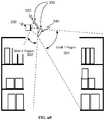
- FIG. 5is an schematic representation of an exemplary configuration of two rows of camera modules aligned within a shelving aisle
- FIG. 6is a schematic representation of an exemplary configuration of a suspended camera module
- FIG. 7is a schematic representation of an exemplary camera module rail enclosure body
- FIG. 8is a schematic representation of a suspended camera module
- FIG. 9Ais a bottom schematic view of a camera module body compatible with ceiling tiles
- FIG. 9Bis a top schematic view of a camera module body usable within a ceiling tile structural system
- FIG. 10is a schematic representation of camera and camera module spacing
- FIG. 11is a schematic representation of an exemplary single-point camera module
- FIG. 12is a schematic representation of mounted camera modules
- FIG. 13is a schematic representation of an alternative mounting system for camera modules
- FIGS. 14A and 14Bare schematic representation of camera modules, redundant power and network connectivity, and modular use of camera sub-system units
- FIGS. 15A-15Eare exemplary cross sectional profiles of camera modules
- FIG. 16is a schematic representation of a flexible camera module
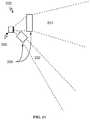
- FIG. 17is a diagram representation of a lens used in augmenting optical observation of a shelf
- FIG. 18Ais a schematic representation of camera coverage and camera coverage overlap for a shelf as collected by a cameras
- FIGS. 18B-18Dare schematic representations of camera coverage and camera coverage overlap for a shelf as collected by a cameras after use of a corrective optical system
- FIG. 19A-19Care exemplary lighting integration form factors of different camera module variations
- FIGS. 20 and 21are schematic representations of camera module component architecture for operational redundancy[[.]];
- FIG. 22is a schematic representation of power and network connectivity cabling connecting camera modules
- FIG. 23is a schematic representation of a monitoring network branch
- FIG. 24is a schematic representation of a connection port
- FIG. 25is a schematic representation of an exemplary wire management solution.
- FIGS. 26-29are generalized schematic representation of variations of split-field optical systems.
- a system and method for ubiquitous video monitoring across an environmentfunctions to enable a network of cameras to be efficiently installed and operated for collecting media, in particular, video and still images.
- the collected media of the systemis preferably used in large-scale computer vision (CV) driven applications.
- the system and methodpreferably involve the setup of multiple camera modules along, or suspended from, the ceiling region of an environment.
- the system and methodmay alternatively include installation across other regions and/or infrastructure of an environment.
- a particular attribute of the system and methodis the use of easily installed camera modules, which can be daisy-chained or otherwise connected to form a monitoring network. When used within a commercial space or suitable environment, the monitoring network can be distributed across the ceiling and other regions for detailed visual monitoring. Other installation approaches may additionally or alternatively be used with the system and method.
- videomight mean a common video format such as NTSC, PLA, MPEG, 4K, HEVC etc.
- Videomay also mean a sequence of individual still images whose place in time is monotonic. Those images may similarly be in a wide range of formats, including Raw, JPG, PDF, GIF, BMP, HEIF, WebP, and/or other suitable media formats.
- the systemcould additionally be applied to a single camera and/or audio monitoring and may additionally include other forms of sensing that may be used independently or in combination with video monitoring. These might include lidar, sonar, infrared, ultraviolet, radio frequency, capacitance, magnetic, scales, pressure, volume, climate sensing, and the like.
- system and methodmay additionally or alternatively be used in distributing other computer input or output devices across an environment.
- the system and methodcan be used in the collection of sensor data and/or generation of an output in addition to or as an alternative to video and/or image data.
- Other forms of devicessuch as microphones, bluetooth beacons, speakers, projectors, and other suitable devices could additionally or alternatively be integrated into system modules that may be installed across an environment.
- the system and methodare primarily described as it relates to image-based video monitoring.
- the system and methodare preferably used for applications that utilize ubiquitous monitoring across an environment.
- ubiquitous monitoringor more specifically ubiquitous video monitoring characterizes pervasive sensor monitoring across regions of interest in an environment.
- Ubiquitous monitoringwill generally have a large coverage area that is preferably substantially continuous though discontinuities of a region may be supported. Additionally, monitoring may monitor with a substantially uniform data resolution.
- Large coveragein one example, can be characterized as having greater than 95% of surface area of interest monitored. In a shopping environment this can mean the shelves and product displays as well as the shopping floor are monitored.
- Substantial uniform data resolutionpreferably describes a sensing configuration where the variability of image resolution of different areas in the environment is within a target range.
- the target range for image resolutionis sufficient to resolve product packaging details for product identification.
- Ubiquitous monitoringmay optionally include the characteristic of redundant monitoring. This may involve having redundant coverage from multiple vantage points. For example, an item on a shelf may be visible by two different cameras with adequate product identification resolution and where the cameras view the item from different perspectives. In an environment like a grocery store this could mean 10-200 cameras distributed per an aisle in some exemplary implementations.
- system and methodmay have particular potential benefits to a large environment, the system and method has potential benefits and applications within small environments. Adaptability to different environments is an exemplary benefit of the system and method.
- the system and methodmay be used for any suitable video monitoring application.
- the system and methodis for CV-based computing applications, which may include automated self-checkout, inventory tracking, security surveillance, environmental event detection and tracking, and/or other suitable applications.
- automatic checkoutis used as the main exemplary application of the system and method, but any suitable application may be used.
- Automatic checkoutis primarily characterized by a system or method that generates or maintains a virtual cart during the shopping process of a customer (or group of customers) with the objective of knowing the possessed items when a customer leaves a store or is ready for checkout.
- the system and method as described hereincan be used to automatically generate an itemized checkout list for a customer.
- An automatic checkout systemmay additionally automatically charge an account of a customer for the total of a shopping cart.
- the automatic checkout systemcould alternatively be used to expedite entry of items for payment.
- the system and methodmay alternatively be used to account for the removal of a good by a customer such as in a library, a rental store, a warehouse, or any suitable item storage facility.
- the system and methodmay alternatively be used to permit or restrict access to locations, or to charge for such access.
- the systemcan be made to work for a wide variety of shopping environments such as grocery stores, convenience stores, micro-commerce & unstaffed stores, bulk-item stores, pharmacies, bookstores, warehouses, malls, markets, and/or any suitable environment that promotes commerce or exchange of goods or services.
- the systemmay be used in conjunction with law enforcement, or similar systems, to identify individuals who are not abiding by the rules of the systems.
- the systemand in particular the camera modules, are preferably easily installed and activated.
- the camera modulescan be mounted using standard fixtures used in many stores. In some instances this may involve using existing store infrastructure such as those for lighting systems, and repurposing those for installation of the camera modules. In other instances, it may involve standard device installation familiar to contractors and electricians installing lighting systems and other common devices. In some variations, the installation of the devices is substantially similar to the structural challenges of installing traditional lighting fixtures.
- the camera modulesmay simply need to be connected together with a set of cables. In some variations this my involve a set of data and power cables. In some variations, this may involve a single integrated cable for data and/or power connections such as using a power-over-ethernet (PoE) cable or a custom cable.
- PoEpower-over-ethernet
- the system and methodadditionally prioritize automatic configuration over customized configuration.
- the camera modulescan be substantially self-initializing and the network of camera modules can self-organize to coordinate environmental video monitoring.
- the self-calibration and configurationcan minimize the amount of training for a worker installing the system.
- Such easy setupmay be important to enabling an environment to come online with computer vision monitoring capabilities quickly.
- the orientation and positioning of the cameras within the environmentis made less necessarily precise.
- the form factor of the camera modulescan simplify alignment and positioning of devices for desired ubiquitous monitoring. Camera alignment can be designed with specifications within the normal tolerances of standard contractor installations. Additionally, self-configuration reduces reliance on specialized technicians for bringing up and configuring the camera modules individually.
- the system and methodcan address calibration by “saturating” an area with cameras and autonomously detecting the camera topology within the environment.
- the systemcan be used in creating a high-density imaging system within an environment. In this way a worker installing a camera module can be alleviated of worrying about the exact orientation and positioning of the cameras.
- the system and methodcan additionally have easer maintenance.
- Various potential implementations of the system and methodcan address various scenarios to simplify responding to system issues and/or updating the system.
- component redundancy designed into the camera modulescan allow the monitoring network to be resilient to individual failures by failing over to redundant data and/or power systems. This can increase uptime of the system.
- an installed camera modulee.g., a camera module not functioning properly or an old version of a camera module
- a new camera module 200can be replaced by a new camera module 200 . Such camera module updates can be performed without having downtime on other camera modules.
- the system and methodcan enable efficient configuration of camera compute modules.
- fields of view for a series of camerascan be coordinated such that they efficiently cover a shelf, aisle, or other region of interest in a manner preconfigured through the arrangement and orientation of the cameras in the camera modules. In some variations, this may enable the number of cameras for an install to be significantly reduced.
- some embodiments of the system and methodcan utilize commodity imaging components to provide an economical solution to outfitting an environment. The system and method can be operational using cheaper and more commodity components such as small format camera sensors (e.g., camera with a camera sensor sized: 1/4 in., 1/3.2 in., 1/3 in, 1/1.7 in., and/or other sizes).
- the system and methodcan be a visually unobtrusive.
- the systemmay blend into the environment as a standard infrastructure system that can go mostly unnoticed to people in the environment.
- CV-based processingmay leverage CV-based processing to address bandwidth data storage limitations.
- CV-based processingcan enhance information retention through dynamic information processing that involves CV-based metadata extraction, media processing, and tiered storage solutions.
- a system for outfitting an environment with ubiquitous video monitoring of a preferred embodimentcan include a monitoring network 100 comprised of a set of camera modules 200 mounted and interconnected within an environment.
- Each camera module 200 of the set of camera modulespreferably includes at least one camera 220 and at least two connection ports 230 .
- the set of camera modules(or at least a subset of camera modules) serially connect through the connection ports 230 , wherein a physical connection is established between connection ports 230 of network adjacent camera modules.
- the systemcan be used to form a connected chain of camera modules 200 with shared network and/or power connections.
- the systempreferably enhances feasibility of implementing a ubiquitous video monitoring system.
- the systemincludes various factors that benefit the ease of installation as well as the reliable monitoring of the environment for serving a CV-driven application. Some variations may include multiple cameras mounted in pre-configured arrangements in an enclosure, component and connection redundancy, hotswap capabilities, corrective optical systems, and/or other features.
- the systemis preferably used for CV-driven applications like automatic checkout but can be used for other types of applications.
- the camera modulesare devices that include multiple connection ports 230 for receiving power and/or network connectivity and relaying power and/or network connectivity to connected camera modules 200 .
- Camera modules 200can be chained together by connecting with one or more cables that provide data and/or power transport between the camera modules 200 .
- the camera modules 200have an enclosure body 210 with an extended length profile that has connection ports 230 on opposing ends of the camera module 200 (e.g., a first connection port 220 on a first side and a second connection port 220 on a second side opposite the first side).
- the elongated length profilefunctions to promote easier installation of cameras in a pre-configured arrangement along a path (e.g., down an aisle in a grocery store).
- the camera modules 200are suspended fixtures interconnected by ethernet or PoE cables.
- the camera modules 200can contain one or more cameras 220 and possibly a set of computational components to facilitate local processing of media. In some cases, CV-based processing can be performed locally to mitigate the amount of media that is communicated across the monitoring network.
- the camera modulescan include redundant data and/or power connections for network resiliency. If a power connection fails, a redundant power connection can keep the camera module 200 powered. Similarly, redundant network connections can maintain network connectivity if one connection encounters an issue. Additionally, in some variations, a camera module 200 can include a hotswap control system for removal and reinstallation of a camera module 200 such that camera modules 200 can be changed while the system maintains operation.
- the monitoring network 100functions to coordinate the collection of video media data from across a number of camera modules 200 that are connected as a camera module network.
- a CV-driven applicationwill generally operate from data collected from one or more monitoring networks 100 .
- the camera modules 200may be connected in series within the monitoring network 100 .
- the camera modules 200may alternatively include branches in the monitoring network 100 .
- the monitoring network 100can be comprised of just video camera modules.
- the monitoring network 100may additionally include nodes comprised of other types of sensor modules/devices.
- a monitoring network 100 within an environmentis comprised of a set of sub-networks formed by a serial connection of a set of camera modules 200 .
- a serially connected monitoring networki.e., a daisy-chain network configuration
- each camera module 200connected to at least one other camera module 200 such that the string of camera modules forms a chain.
- the series of camera modulesmay be the series connection of multiple network nodes each having a number of camera connections.
- a first end (and/or terminal end) of the chaincan include connections back to the rest of the system.
- a configurationcould additionally include interconnection branches.
- a daisy-chain of camera modulescould split at some point so that there are two or more branches.
- the number of camera modules included in a serial connectioncan be any suitable number.
- the number of camera rails in seriescould be just two, but more generally will be more than ten and could be any suitable number (e.g., 40 camera modules, 100 camera modules, 1000 or more camera modules, or even more).
- the set of serial sub-networksmay all be connected back to one or more points for centralized compute and/or power supply.
- the monitoring network 100can be a star pattern, such that each camera module 200 is connected to a single, central component.
- the central componentcould be a primary camera module 200 (e.g., a hub camera module), but could alternatively be an alternative central component interfacing with the different camera modules.
- Still another configurationis a loop or ring that is connected at two or more ends.
- a combination of one or more of the above or alternative topologiesis also possible.
- the systemmay additionally be compatible with external cameras, imaging devices, other suitable sensor units, and/or output systems.
- camera modules 200may additionally include compatibility to facilitate a connection with an external camera such as an IP camera.
- An external camera connectionmay alternatively be achieved through an alternative channel such as through an external camera interface on a local computing system.
- an external camera module 200can include similar operative components of a camera module 200 but collects an external video stream of an external imaging system instead of a video stream from an internal camera.
- the enclosure body 210 and form factormay be altered to accommodate interfacing with a variety of camera types. In this way, existing cameras and surveillance systems can be retrofitted to integrate with the monitoring network 100 and the system.
- the monitoring network 100is preferably installed in a distributed manner across an environment.
- the systemis preferably adaptable for customizing the video monitoring so that focus is appropriately directed at subjects of interest.
- the subjects of interestinclude the products as they are stored and displayed in the store and areas where customers, workers, or other agents interact.
- various approachesmay be applied in installing and configuring the camera modules 200 of the monitoring network 100 .
- a monitoring network 100may employ a variety of such configuration variations to address different monitoring scenarios in the environment.
- the camera module 200 of a preferred embodimentfunctions as an imaging device that is positioned within an environment.
- the camera module 200can function as one unit of the building blocks of the system in constructing and laying out a monitoring network 100 .
- a monitoring network 100is preferably comprised of a set of camera modules 200 that cooperatively act to monitor and collect data from across the environment. More particularly, a monitoring network 100 can be one or more sets of physically interconnected camera modules 200 .
- a camera module 200preferably includes at least an enclosure body 210 , one camera 220 , and a set of connection ports 230 .
- the camera module 200preferably facilitates image monitoring, but additionally facilitates fixturing/mounting, network configuration, system integration, CV-based processing and data management, and/or or other suitable aspects.
- the enclosure body 210has an extended length profile, and the camera module 200 is configured with mounting mechanisms to be suspended horizontally from a ceiling or elevated structure. There is preferably a plurality of camera modules 200 used for any suitable instantiation of the system.
- the camera modules 200 of a monitoring network 100may be of a uniform type and form, but a set of different camera module types can similarly be used.
- a set of camera module typesthat can be used to address different challenges when installing in an environment.
- Functionality and internal elementssuch as the cameras and/or computational components are preferably substantially similar across different camera module types, but the enclosure body 210 may be customized to accommodate different uses.
- the camera module typesmay include different form factor variations and/or capability variations.
- the different form factorscan accommodate different applications and scenarios where different shapes and/or sizes are more applicable.
- Some exemplary different camera module form factor typescan include suspended camera modules, mounted camera modules, flexible camera module strips, single-point camera modules, and/or any suitable type of camera module 200 . Additionally, there may be different sizes or shape variations of each of these.
- Capability variationsmay enable different capabilities to be enabled and integrated at different portions of the monitoring network 100 .
- Capability variationscan include cameras with varying arrangement, orientations, camera counts, camera angle configurations, camera optical systems, enclosure body sizes and form factors, processing capabilities, and/or other suitable variations of a camera module 200 .
- Camera module typescan have varieties in terms of lengths, capabilities, and/or other properties.
- capability variationscan be two camera module types: a normal camera module 200 and a hub, central, master, or primary camera module 200 .
- the primary camera modulemay include additional computing resources to facilitate processing data of the system. As the additional computing resources may be needed in limited supply and contribute to cost, they may be provided as specialized camera modules that can be used as needed in a monitoring network.
- the camera modules 200are preferably interconnected by wired conductive connections that interface with the camera modules 200 through at least one of the connection ports 230 .
- the connection ports 230can connect power and/or a data connection (e.g., network connectivity). Wireless communication may alternatively be used for one or both of power and/or data connectivity.
- multiple sub-networks of camera modulescan be integrated as shown in FIGS. 1 and 3 .
- camera modules 200may be designed with redundant or optional components that can be enabled for different monitoring network 100 configurations.
- the camera modulesmay additionally include a Wi-Fi module or other wireless communication module so that a camera module 200 or a subnetwork of camera modules could communicate wirelessly with the system.
- Wireless power deliverymay additionally or alternatively be used.
- a camera module 200preferably includes at least two connection ports 230 such that the camera modules may be connected in series.
- a first connection port 230can be positioned on one end and the second connection port 230 can be positioned on the other end.
- the connection ports 230may alternatively be positioned in any suitable arrangement (e.g., side-by-side). Some variations can include three or more connection ports such that a monitoring network 100 can include multiple branches.
- one end of a camera module 200can include two connection ports 230 such that a series of camera modules 210 can branch or merge at that end of the camera module 200 .
- the camera modules 200are part of a modular set of components available through the system, which can be used in customizing configuration and arrangement of the camera modules 200 to be customized to a particular environment and/or use case.
- Different environments and use casescan have different requirements. Environments may have various static or changing visibility expectations that can impact the spacing and arrangement of camera modules.
- the use case or objective of the systemcan have a similar impact on arrangement. For example, when used in a store or a warehouse, the layout of inventory and shelving can be a factor when configuring camera modules. As another example, using the system for detailed inventory and customer interactions may have different coverage requirements.
- the systemcan be used for monitoring items on the shelves and interactions with those items.
- the installation configuration of one or more camera modules within the monitoring networkcan be designed to specifically address challenges of monitoring inventory and inventory interactions.
- the camera module 200 design and featuresmay be customized for specific installation plans.
- a dual-angled center camera module 200can be positioned in the upper region or above the center region of an aisle to monitor both sides of the aisle. Some stores have existing infrastructure for suspending lights down the middle of aisles. In some variations of the camera module 200 , a camera module 200 with lighting fixture integration could be used so that a) the camera modules may be mounted to existing infrastructure by replacing existing lighting fixtures, and/or b) the system can provide lighting to the environment in those regions.
- another installation configurationcould have at least two rows of connected camera modules running down either side of an aisle in a store.
- installing the camera modules 200 above and preferably in front of the face of a shelfmay enable the camera module 200 to both monitor items on the shelf opposite the aisle and monitor when and approximately where customers interact with the shelf face closest to the camera module 200 .
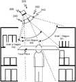
- a single cameracan have a field of view incident on a first shelf face and the opposite edge of the field of view incident on the upper region of the opposite shelf face as shown in FIG. 5 .
- a dual-angle camera module 200may have one camera directed substantially in a first orientation (e.g., downward) where a first shelf face is within the field of view and a second camera directed in a second orientation (e.g., outward diagonally) where the second/opposite shelf face is within the field of view of the second camera.
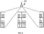
- the camera modulesmay be installed so that they run perpendicular to a shelf face or a target region. In another variation, the camera modules may be installed so that the camera module 200 collects image data spanning multiple aisles as shown in FIG. 6 .
- the enclosure body 210 of a preferred embodimentfunctions as a frame for mounting the cameras 220 , mounting and protecting computational components of the camera module 200 , and/or housing other elements of the camera module 200 .
- the structural bodyis preferably a solid encasement that contains the computing components.
- the enclosure body 210can include a structural body with at least one defined camera mount.
- a preferred variation of camera module 200can include a plurality of cameras 220 wherein the plurality of cameras 220 are mounted with a spaced arrangement across the enclosure body 210 in different defined camera mounts.
- the enclosure body 210can additionally include one or more mounting mechanisms that function to facilitate positioning, fixturing, or otherwise physically coupling the camera module 200 in place.
- the structural bodyis preferably enclosed, but alternative form factors such as an open tray could also be used.
- the structural bodycan be made of any suitable a material such as plastic, aluminum, steel, a composite, or any suitable material.
- the structural bodyis fiberglass, which could minimize signal interference.
- a structural bodycan be a single piece design, but the structural body can alternatively include multiple interconnecting components.
- the structural bodyis preferably a static element with one or more defined cavities for holding the camera and computational components.
- the camera modules 200support “daisy chaining” or “stringing” camera modules across an environment. Different form factors of the structural body can be used to accommodate installation in different types of sites. Two preferred variations include a rail structural body, tile structured body, and/or a compact structural body.
- an enclosure body 210can have a rail-shaped as shown in FIG. 7 , tube-shaped enclosure as shown in FIG. 8 , or any suitable shape.
- the shapeis preferably straight but curved, arced, or angled enclosures could additionally have an extended length profile.
- An elongated form factormay function to facilitate arranging cameras along a long run in the environment. For example, for a given length of space, an elongated form factor can have a lower number of units-per-length that need installation thereby reducing labor for installation.
- a rail structural body variationcan come in different lengths. Some exemplary lengths may include lengths that are somewhere between 3-10 feet. In some instances, a set of different lengths may be used: a 2-3 foot enclosure body, a 5-6 foot enclosure body, and a 9-12 foot enclosure body. Any suitable length may alternatively be used.
- the structural bodymay be designed for distributing camera modules 200 by “tiling” or “spreading” camera modules as shown in FIG. 9A .
- a tile structural bodycan be an enclosure body with a form factor that has at least one substantially planar face and as such can be a plate or sheet.
- the planar facewill generally be in the shape of a square or rectangle but any suitable shape may be used.
- the planar facepreferably is used to expose the cameras while the opposite side is preferably used to expose connector ports and optionally house the components of the camera module.
- a structural body variationmay function to make the camera modules 200 compatible with ceiling tile infrastructure as shown in FIGS. 9A and 9B .
- the camera modulescan be installed by replacing existing ceiling tiles with a tile variation of the camera module (i.e., a camera module tile).
- a camera module tilecan have a structural surface shaped two feet by two feet, two feet by four feet, or have any suitable ceiling tile compatible size.
- the camera module tilesare preferably compatible for drop in installation to t-bar or suspended ceiling fixtures used for drop ceilings as shown in FIG. 9A .
- the structural bodycan be designed for adding on to or retrofitting an existing ceiling tile or material.
- the camera modulemay be designed such that the cameras 220 project through the ceiling tile or material such that the cameras view the target region.
- Some or all housing of camera module componentsmay be designed to be positioned above the ceiling tile out of site as shown in 9 B.
- the rail structural body variation and the tile structural body variation the camera modulesmay be positioned in a regular fashion wherein the arrangement of the cameras can be substantially periodic and regular across multiple interconnected camera modules. As shown in FIG. 10 , a five and half foot camera module rail could be interconnected with six inch spacing between camera module rails such that pairs of cameras in the monitoring network have three foot spacing.
- the structural bodymay be designed to be compact such that the camera modules 200 can be installed at distinct points.
- the single-point camera modulemay include a single camera mount but more preferably will include multiple camera mounts directed in different directions as shown in FIG. 1 i .
- a single-point camera modulecan be a suspended camera module 200 .
- the mounting mechanism of the single-point camera modulecan be any suitable mechanism to fasten or position the camera module 200 .
- a single-point camera modulemay include the variations described herein such that it can connect to one or more camera modules through a wired connection.
- a single-point camera modulein particular may alternatively make use of a wireless communication channel such that only power is delivered through a wired connection.
- a single-point bodymay be designed for more point-based installations where the interconnections of camera modules are not substantially interconnected in close proximity as in FIG. 10 .
- the rail structural body variationis primarily used as an example but any suitable variation could alternatively be used.
- An enclosure mounting mechanismis preferably a fastener mechanism or design feature of the enclosure body 210 that promotes positioning, attaching, or otherwise physically coupling a camera module 200 to an outside structure.
- the nature of the mounting mechanismcan vary depending on the camera module type. Selected variations are described more below.
- a suspended camera module 200is a form factor that is configured to be suspended from a higher structure such as a ceiling.
- a suspended camera module 200is preferably used in monitoring an environment from the ceiling region, and it may be straightforward solution for commercial spaces that already leverage suspended fixtures such as lights and signage.
- the mounting mechanism of a suspended camera module 200preferably accommodates one or more cable connection points.
- the enclosure body 210can include two threaded lamp tube fastening points along the length of the enclosure body 210 and on opposing sides such that two cables can be used to horizontally suspend the camera module 200 from the ceiling.
- a mounting mechanisme.g., protruding bolts
- a mounted camera module 200is preferably configured to be rigidly fastened or attached to another rigid structure.
- camera modulesmay be mounted directly to a shelf as shown in FIG. 12 so as to horizontally extend across an aisle of adjacent shelves.
- the mounted camera module 200can include many of the suspended camera mount design considerations. However, as a mounted camera module 200 may be in closer proximity to users, mounted camera modules preferably include design considerations to more rigorously protect from tampering and abuse.
- the mounting mechanismcan be defined to include bolt through-holes so that the mounted camera module 200 can be securely fastened to another structure.
- a mounted camera module 200may additionally include a protective camera cover so that wear-and-tear near the camera mount areas can be addressed by replacing the camera cover as opposed to changing the camera module 200 or the camera.
- the systemmay include a bracing structure that acts a rigid structure to suspend or otherwise position a mounted camera module 200 .
- a shelf-adapter structuremay attach to the top shelf of a shelving unit and suspend a lever outward to a correct mounting position. This may function to simplify installation along aisles and to promote controlled positioning of a camera module 200 relative to the shelf face.
- the camera mountsfunction as locations where a camera is mounted.
- the camera mountscan be defined cavities or recesses of the structural body such that cameras can have an outward view of the environment.
- the camera mountsmay additionally facilitate connected camera units such that in place of fixed cameras, interchangeable camera units can be connected or plugged into a port accessible through the camera mount and held in the camera mount. Interchangeable camera units may enable camera customization and upgrades.
- the camera mountsmay be statically positioned. Alternatively, the camera mounts may be repositioned either through physical manipulation or through a controlled camera actuator system.
- a segment of the enclosure body 210 with extended length profilecan include a camera mount section that can be rotated about the central axis of the enclosure body 210 to rotate the angle of the camera.
- camera anglemay be customized during final assembly of the camera module 200 .
- a camera module 200may include multiple sub-assemblies that can be connected to form a complete camera module 200 .
- a suspended camera module 200may be formed by connecting two partial camera module halves through a mechanical and wired connector.
- Each camera module unitmay include the necessary components.
- some camera modulesmay omit or contain particular components such that camera module units may require being connected in a combination such that particular component requirements are fulfilled.
- a special processing camera module unitmay be required to be connected to any segment of a camera module assembly for every six active cameras.
- each camera module 200may include connectors on one or both ends such that any suitable number of camera sub-system units 202 (i.e., camera module units) can be combined to form a camera module assembly.
- a camera sub-system unit 202is preferably a computing device such as a PCB board or enclosed computing device.
- a structural bodycan have internal fixtures to mount varying numbers of camera sub-system units 202 as shown in FIGS. 14A and 14B .
- the different sub-system units 202each support some number of cameras and thus the number of cameras in a camera module 200 can be adjusted by selecting the number of enclosed subsystem units 202 . In this way, camera modules may be flexibly customized and repurposed for different environment challenges.
- the structural bodycan be a substantially rigid material such as steel, fiberglass, aluminum or plastic, but any suitable material may be used.
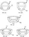
- the enclosure body 210can be a length of tubing, bar, or other form of self-contained rail as shown in FIG. 15A , but may alternatively be an open trough.
- Computational componentsare preferably contained within a defined recess or hole of the enclosure body 210 .
- the cross section of the structural bodypreferably includes subsections or structures that extend upward, which functions to act as containing walls and to provide structural support during suspension. As shown in FIGUREPRVS 15 A- 15 E, various profiles may be used.
- a trough designmay additionally include a cover component to at least temporarily seal contained components within the enclosure body 210 as shown in FIGS.
- Downward facing walls of the structural bodycan be angled so as to position cameras at an intended angle.
- a right angled extruded barcan have camera mounts oriented on each face so as to monitor different directions as shown in FIG. 15B .
- the anglemay be adjustable.
- the structural bodymay have a section with multiple facets and/or camera mount options as shown in FIG. 15C so that positioning of the camera can be selected during manufacturing and/or installation.
- the camerasmay be mounted ‘proud’ as shown in FIG. 15D , or recessed slightly as shown in FIG. 15E so that they are mechanically protected while still having a full optical view of their surroundings.
- a flexible camera module stripcan facilitate a camera module 200 being adhered or otherwise attached to a surface.
- the structural body of flexible camera module stripcan be bendable along substantial portions of its geometry as shown in FIG. 16 . Some portions may still be made rigid to protect rigid internal components.
- the flexible camera module stripincludes an adhesive backing opposite the side of the camera mounts such that the flexible camera module strip can be installed by simply applying it to a surface.
- the cameras 220 of a preferred embodimentfunction to collect image data.
- the image datais preferably a video stream but could alternatively be periodically collected photographs.
- the video streammay or may not include audio recorded by a microphone.
- the cameras 220may alternatively be used to collect other forms of image data.
- a camera 220 of the systemmay collect any suitable combination of visual, infrared, depth-based, lidar, radar, sonar, or other types of imagery.
- the set of cameras used within the system or a single camera modulecan have varying resolutions, fields of view, aperture settings, frame rates, capabilities, or other features.
- the cameras 220are preferably statically mounted in a camera mount of a camera module 200 .
- the cameras 220 and/or other camera mountsmay be actuated such that a camera can be redirected during use.
- An individual camera module 200preferably includes at least one camera 220 , but may alternatively include multiple cameras 220 .
- Multiple cameras 220may be mounted at different locations on a camera module 200 .
- the cameras 220can be mounted to have distinct positions and/or directions such that the cameras 220 have a configured arrangement where the arrangement characterizes spacing and relative orientation.
- multiple cameras 220are mounted so as to have a distinct field of view, which may be overlapping or non-overlapping with a field of view of another camera 220 in the monitoring network 100 or the camera module 200 .
- multiple cameras 220may be mounted at opposing ends of an extended length camera module 200 .
- a subset of cameras 220may alternatively be mounted so as to capture substantially similar fields of view but using different imaging technologies.
- a first subset of camerasare mounted with a first angle orientation.
- all cameras of a modulemay have the same angular orientation wherein the image planes that are substantially parallel.
- a first subset of camerasare mounted with a first angle orientation and at least a second subset of cameras are mounted with a second angle orientation.
- a dual angle variationwill have two subsets of cameras with different angular orientations. For example, a group of cameras may be directed in one direction and another group directed in a second direction as shown in the exemplary application of FIG. 4A .
- a Tri-angular variationmay be another common variation, wherein there may be two diagonal angle orientations for two subsets of cameras and one downward facing angle orientation of a subset of cameras. Any number of angular orientations may be used.
- the camerasare preferably angled so as to be directed at a target region.
- the target regionis a shelf or more specifically, the shelf face.
- the camera module 200will be mounted above and in front of the shelf face. Shelves have varying heights depending on the store and type of goods.
- the camerais mounted above the region of the shelf face of interest.
- the camera modulemay be offset from the shelf face horizontally by a few inches (e.g., five inches) to several feet (e.g., 15 feet). In general the camera will be somewhere between three to eight feet displaced from the shelf face in a horizontal direction.
- the cameraswill often be elevated above the top surface of the shelf with vertical offset of 0 feet (i.e., level) to 10 feet. Though the camera may be below the top in some cases.
- a subset of cameras of a camera modulemay be mounted with an angle orientation configured to capture a first shelf face
- the cameramay be mounted between two opposing shelf faces.
- the angle orientation of camera mountingsis preferably configured to target the shelf faces. More specifically, a subset of the cameras are preferably mounted with an angle orientation that is configured to capture a first shelf face of a first shelf and a second shelf face of a second shelf when the camera module is mounted above and between the first and second shelves as shown in FIG. 5 .
- the first and second shelfwill generally oppose each other. In this way, a single camera can have two shelves in the field of view.
- the first shelfmay be captured to identify products and/or detect item interactions by a customer.
- the second shelfmay be captured for similar reasons, but may additionally be monitored so as to detect when an interaction event occurs with the shelf.
- cameras 220may be mounted as camera pairs, wherein a subset of cameras are paired in a depth perception arrangement, which functions to enable depth calculation to be performed. Depth sensing and estimation could additionally or alternatively be performed using alternative techniques including single camera depth prediction.
- the depth perception arrangement of camera pairsis preferably spacing between one and ten centimeters apart, but any suitable spacing may be used.
- Multiple camera pairsare preferably arranged along the enclosure body. For example, a six foot camera rail could have two camera pairs spaced three feet apart directed at a first orientation (referred to in this example as first-angle cameras.
- two additional camera pairsmay each be positioned along side one of the first-angle camera pairs such that the second-angle camera pairs are similarly spaced three feet apart.
- the second-angle camerasare oriented with a second angle.
- N-angle camerasmay be used.
- the cameras 220can additionally include an optical system 320 which functions to better target monitored objects. While the cameras 220 may provide general surveillance, cameras 220 in CV-driven applications may have particular benefits when customized to collecting image data of particular regions in an environment. For example, in an automatic checkout usage scenario, the suspended camera modules will preferably be able to reliably provide image data on shelved items. When the camera module 200 is suspended, the plane of the shelves will generally be askew from the field of view of the camera's 220 , which could result in a keystoning distortion effect of the shelf and products. Additionally, the focus plan of a camera will generally not be parallel to the shelf and portions of the shelf may be out of focus despite focusing the camera on some region. In some instances, the degree of focus and out of focus of the items may not be an issue.
- a corrective optical system 320can facilitate correcting for orientation misalignment of the camera imaging plane and a subject plane, which can mitigate distortion and/or improve focus for regions of interest.
- the optical system 320preferably optically shifts and/or tilts the focus plane of a camera to counteract a portion of distortion and/or focus when imaging a target subject.
- Claim 16 AA corrective tilt shift (e.g., Scheimpflug) optical system can create a wedge shaped depth of field that can be aligned with the subject plane (e.g., the front plane of a shelf).
- the corrective optical systemmay apply an optical shift, which can correct distortion. Additionally or alternatively, the optical system may apply a tilt to alter the focus plane to better align with the target region of a shelf face.
- a lenscan be positioned non-parallel or tilted relative to a camera imaging plane to correct imaging for shelf viewing.
- the FIG. 17is not to scale so as to better illustrate the basic principles of one optional optical system.
- a compound lens or other optical setupcan additionally be used.
- other optical system variationssuch as a lenticular or alternative lens used for a light field camera or a plenoptic camera, use of multiple directed cameras, or other suitable cameras and/or optic systems could be used in adapting the collection of image data for a particular target.
- optical systemmay be applied which is described in more detail in the section below.
- a camera module 200can additionally include other supplementary components used in offering additional or enhanced sensing or functionality.
- Supplementary componentsmay include microphones, speakers, area lighting, projectors, communication modules, positioning system modules, and/or other suitable components.
- the camera module 200can include microphones such that a distribute audio sensing array can be created. Audio sensing can be used in identifying, locating, and collecting audio input from different locations. For example, a monitoring network 100 with microphones can triangulate sounds to determine location within the environment. This can be used to facilitate CV-based tracking. This could alternatively be used in enabling audio-based interactions with the system.
- the microphone array provided through the monitoring networkmay be used to facilitate in-store audio-interfaces. For example, a customer could issue audio commands from any place in the store, this could be synchronized with the CV-driven application which may be used to associate a detected audio command with a user entity or account issuing that command.
- the microphone arraymay be used in differentially locating, processing, modifying, and responding to audio sources as discussed in published U.S. patent application Ser. No. 15/717,753 filed 27 Sep. 2017, which is hereby incorporated in its entirety by this reference.
- the camera module 200can include integrated speakers, which can function to enable audio output. In one implementation, this may be used to simply play audio across an environment.
- the speakersare preferably individually controllable across the monitoring network, and targeted audio could be played at different regions. In the automatic shopping experience, this can be used in providing augmented audio experiences as a shopper is tracked through a store.
- the speakerscould additionally be used as a human computer interface output when configuring or maintaining the device.
- a camera module 200could be set to play an audio signal when the camera module 200 enters an error state.
- the camera module 200can include a lighting system, which functions to at provide general lighting.
- the lighting systemcould include integrated lights. Integrated lights could be LED lights or other suitable light sources that are built into the camera module 200 .
- the lighting systemcould alternatively be a set of lighting fixtures such that external lights could be connected to.
- a lighting fixtureis designed to power traditional lights such as fluorescent lights, LED lights, incandescent, CFL lights, and the like could be installed and powered by the system.
- An integrated lighting systemcan enable the infrastructure of a store to be minimized by not needing to set up separate lighting and camera systems.
- the structural infrastructure used to support and optionally power existing lightscan be repurposed for fixturing and/or powering the camera modules 200 .
- installing the camera modules 200 and monitoring networkmay serve to upgrade environment lighting as well as adding advanced monitoring and CV-driven applications.
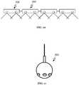
- the enclosure body 210can be adjusted to support integration of the lighting system as shown in FIG. 19A .
- a camera module 200could have a form factor such that they can be installed into pre-existing lighting fixtures.
- a “fluorescent tube” camera module form factor shown in FIG. 19C or a “light bulb” form factor as shown in FIG. 19Bcould be used such that camera modules could be fixtured in place and powered by being inserted into a lighting fixture. Integration of a lighting system can enable the camera module 200 to still provide light like a normal light, but to be enhanced with the sensing and computational capabilities of the camera module 200 .
- These variationsmay communicate wirelessly or have a network connection port that is exposed when inserted in the electrical fixture.
- the lightingcould additionally be dynamically and individually controlled by the system.
- the on/off state, brightness, colors, directionality, and/or other propertiescould be individually controlled.
- lightingcould automatically be adjusted based on observed objects in the environment.
- the lightscould automatically turn on and off or dim based on the location of the people (e.g., workers) present in the environment.
- the camera module 200can include a projector system, which functions to project structured lighting. Images can be projected at different locations using a projector system.
- the cameras of the systemare preferably used as a CV-driven sensing input that can be used in various applications, and a projector system can be used as a system output to compliment the computational input from the cameras.
- the projectorscan be individually controlled and can similarly be used in combination with a CV-driven application.
- the camera module 200can include a communication module, which functions to facilitate a communication or data network within the environment.
- the communication modulecould be a WiFi router used to provide wireless internet within the environment.
- the communication modulecould alternatively be a Bluetooth module used for Bluetooth beaconing or other applications. Any suitable type of communication module could be integrated into the camera modules or a portion of the modules to provide a wireless communication channel within the environment.
- the camera modulesmay include a positioning system, which functions to act as a mechanism for local positioning within the environment.
- a positioning systemwhich functions to act as a mechanism for local positioning within the environment.
- an RF-based positioning systemcould be used to track RFID tags in the environment.
- sensors and devicescould additionally be included such as environmental condition sensors (e.g., smoke alarms, CO 2 monitors, temperature, humidity, air quality, etc.) or other components for different functionality.
- environmental condition sensorse.g., smoke alarms, CO 2 monitors, temperature, humidity, air quality, etc.
- the components of the camera module 200can be architected and designed for operational redundancy.
- the systemcan preferably maintain operation of the camera modules 200 even if one camera module 200 fails. Computational and communication redundancies can enable a sequence of interconnected camera modules to keep operating even when one segment fails.
- a camera module 200preferably has redundant power and/or redundant network connectivity.
- a power control systemmay manage redundant power.
- a network switch or hubmay coordinate redundant network connectivity.
- a camera module 200can include a connector on each end for daisy-chaining, a second connector on each end for forming T- and X-shapes, and a second set of each pair of connectors for redundancy (now 8 connectors in all).
- the pair of pairscan each be collected into a network (e.g., net-A and net-B as shown in FIG. 20 ).
- the four connections that make up net-Aare connected to a common hub, as are the connections that make up net-B.
- Hub-A and hub-Bare then, in-turn connected to hub-C, which connects to the CPU.
- the CPUconnects to the array of cameras. This configuration can be fully robust against the failure of any single connector or of either hub-A or hub-B. Further, if hub-C or the CPU fail, connectivity to the other camera modules in the system are preserved.
- a second CPUis added, and each of the two CPUs is given authority over managing one-half of the camera elements as shown in FIG. 21 .
- each of the two CPUsis given authority over managing one-half of the camera elements as shown in FIG. 21 .
- hub or CPUfails, half of the cameras will stop operation.
- the configuration of the camera module 200 and/or networkpreferably has a significant enough camera density that the camera coverage redundancy is sufficient to handle some camera failures.
- This second implementationcan be further augmented by adding a connection CPU-B & hub-A; and CPU-A & hub-B.
- a camera module 200can include a hotswap control system such that a camera module 200 may be safely disconnected or connected from the system while the system is live and operating.
- the hotswap control systemcan additionally offer continuous protection from short circuits and overcurrent faults.
- Hotswap control systemcan enable hardware updates and fixes to the system to be performed without requiring the system to be powered down.
- a camera module 200may encounter an issue where it needs to be replaced.
- a maintenance workercan rewire network and/or power connections around the camera module (e.g., swapping redundant power or network connections to a subsequent camera module or to a planned replacement), and then remove the camera module causing the issue.
- a replacement camera modulecan then be primed for connection by rewiring the network and/or power connections, and then swapped into the monitoring network 100 .
- the camera module 200preferably includes a set of computational components used in performing local processing, managing state of the camera module 200 and/or interfacing with the monitoring network, other system elements, or remote resources.
- the computational componentspreferably include a subset of components for processing.
- the processing componentscan manage operating state and other operations of the camera modules 200 .
- the camera modulewill include at least one processing unit configured to perform local processing of collected video data.
- the processing componentspreferably function to transcode or transform image data from a camera to a format for digital communication with other resources of the system.
- the processing componentscan include a general processing unit, a specialized processing unit such as a graphical processing unit (GPU), a dedicated computer vision or deep learning processor, and/or any suitable processing component.
- GPUgraphical processing unit
- the processing performed at the processing componentsmay include transforming raw image data to a compressed media format such as a MPEG video format.
- image datamay, at times, be transformed from raw image data to a metadata representation wherein a CV analysis extracts information from the image data.
- the metadata and/or the digital media formatmay be communicated to other camera modules and/or system components.
- the camera modules 200may be configured to selectively communicate video data based on results of local processing of video data.
- Media transformationmay be dynamically set according to “information quality” of the metadata.
- the “media quality” of the resulting media format during transformationmay be indirectly set based on the “information quality”. For example, when the media is transformed into a metadata representation with a high level of confidence, the media format could be reduced to save data storage or bandwidth.
- video mediamay not be stored or communicated if no motion is detected, if no people are present, and/or if other suitable conditions are met.
- a camera module 200may include a processing unit, GPU or other computational elements for each camera, but they may alternatively be shared across cameras.
- the computational componentscan additionally include a communication control system, which can be a networking hub or switch.
- the networking switchfunctions to facilitate network configuration and/or communication in and out of the camera hub. Communication is preferably performed over a wired connection to a connection port of the camera module 200 , but wireless communication may additionally or alternatively be used.
- Internal or external DHCPcan be used to distribute network configuration to the various components of the monitoring network 100 .
- the networking switchis preferably a networking router that is configured to perform DHCP internally when more than one processor is present, wherein the assignment of IP addresses can be managed internally by a master router of the system, such that the camera routers can be self-assembling from a networking perspective. As shown in FIG. 2 , the cameras of the monitoring network may be grouped across a series of such network switches.
- the network switchescan implement a form of Spanning tree protocol (STP) or more preferably rapid spanning tree protocol (RSTP). Other suitable network protocols could similarly be implemented.
- STPSpanning tree protocol
- RSTPrapid spanning
- the computational components of a camera module 200can additionally include an onboard data storage/memory solution, which can be used in storing media and/or data.
- the data storage solutioncould be a hard drive, a solid-state drive, and/or any suitable type of data storage solution.
- the data storage solutioncan be used as a temporarily stash of media and/or data from the camera hub. Data storage may be prioritized for potential long-term relevance.
- the computational componentscan include other common components such as onboard memory, data ports, or other components.
- the camera module 200may additionally include various user interface elements as described below.
- the camera modules 200are preferably designed to simplify configuration, and during normal usage, direct interaction with a camera module 200 may not be needed.
- the camera module 200may, however, include user interface elements to either output information or enable direct control of the camera module 200 .
- User interface elementsmay include basic elements such as buttons or user physical device input elements, displays, indicator lights, speakers for audio signals, and the like.
- the camera module 200may include a control channel mechanism that can enable connected control of a camera module 200 through a secondary device.
- a control channel mechanismcan function to alleviate camera modules from being built with extra components for the rare situations where manual control is required. Control and configuration can preferably be performed through the network connection of a camera module 200 as well.
- a personal computer, a smart phone, tablet, or the likemay be able to connect to the camera module 200 and used as a medium for interfacing with an individual camera module 200 .
- a physical connectionmay be used in the situation where network connectivity to the camera module 200 is not working or is not available.
- a usercan directly connect to the camera module 200 to collect diagnostics, access data, update configuration, control the device, and/or otherwise interact with the camera module 200 .
- a control channel connectioncan be done through a cable such as a wired connector (e.g., a serial port, RJ-45, or a USB connection) or a wireless connection such as Bluetooth or a Wi-Fi network established by the camera module 200 , or any suitable communication channel.
- the camera of the camera module 200may be used as data input channel to the camera module 200 .
- a smart phone appmay enable configurations to be set and then an encoded message can be visually communicated to the camera module 200 through the display or a light of the camera. Output from the camera module 200 may be indicated through indicator lights or other suitable feedback mechanisms.
- connection ports 230functions to facilitate ease of wiring of the camera modules by utilizing serial connections of a sequence of camera modules 200 .
- there are two connection portswhich functions to allow the camera module to serve as a power and/or network connectivity relay wherein input power or network connectivity is received from one connection port 230 , utilized by the camera module, and relayed to at least a second connection port 230 .
- Thismay be used for serial connections of camera modules 200 as shown in FIG. 22 .
- Different connection ports 230 of a camera module 200are preferably substantially the same.
- connection ports 230may also be non-directional where any connection port 230 may be used as an input or output (i.e., supply or relay) of power and/or network connectivity.
- any connection port 230may be used as an input or output (i.e., supply or relay) of power and/or network connectivity.
- the direction a camera module 200 is connectedmay make no difference.
- directionalitymay be built into the design of the camera module.
- one to twenty-five “chains” of camera modulesmay be used to monitor a store.
- the set of camera modules that are part of the monitoring network 100are preferably interconnected through wired connections.
- the wired connectionis preferably used in electrically coupling camera modules for delivering electrical power and/or data communication.
- the camera modules 200preferably include at least two connection ports 230 such that a chain of camera modules can be connected. Each connection port 230 may be exposed on one side of a camera module 200 as shown in the end view of a camera module 200 in FIG. 24 .
- a first connection port 230preferably functions to provide power and/or network connectivity, while a second connection port 230 functions to pass along connectivity to power and/or network access to subsequent camera modules.
- the camera module 200may be designed such that power and/or network connections are independent of connection port 230 .
- a camera module railcould be connected in a series of camera modules with any suitable orientation.
- the camera modules 200may include at least three connection ports 230 such that a chain of camera modules can branch off in different directions.
- each connection port 230includes both a power connection port 232 and a communication connection port 234 .
- the power connection port 232functions to form a connected power delivery network across a network of connected camera modules.
- the communication connection ports 234function to form a communication network across a set of cameras mounted within the environment.
- a connection port 230may include a power connection port 232 , wherein communication may be facilitated wirelessly or in another manner.
- a connection port 230may include only a communication connection port 234 , wherein power may be facilitated in another manner (e.g., having a separate power cord).
- theremay be redundant or secondary power connection ports and/or communication connection ports. Redundant connections may not be inherently redundant or failover but may be designed where port usage is equally prioritized or selected in an alternative manner.
- one of the connection portsmay be a primary one used unless some event triggers use of the secondary/redundant one.
- one preferred variationcan have two power connection ports 232 that connect a DC power connection and two communication connection ports 134 that connect two network cable connections.
- connection port 230Multiple distinct cables may be connected to a connection port 230 .
- an integrated cablemay be used to connect to a connection port 230 and thereby one or more power connection port(s) and/or communication connection port(s).
- the wired connectioncan be a power over ethernet (PoE) port.
- the wired connectioncould alternatively be a USB port (e.g., for a USB Power Delivery connection) or any suitable wired connector.
- a custom cable typecould be used that bundles power and network connectivity.
- the camera module 200preferably includes a power control system that functions to regulate or otherwise manage power supplied to the components of the camera module.
- the power control systemfurther functions to relay or pass power supply between connection ports. For example, a 60 VDC power supply received through a first power connection port 232 is relayed through the power control system (e.g., power management circuitry) to at least a second power connection port 232 .
- the power control systeme.g., power management circuitry
- Another camera module connected to the second power connection port 232can receive power through that connection.
- the power control systemwill preferably step down voltage to one or more desired voltage levels to drive components of the camera module or more specifically components of a camera sub-system unit 202 .
- the camera module 200 or a camera sub-system unit 202can be designed to handle sufficient current loads in the event that a camera module is at the beginning region of a chain camera modules 200 .
- the power system of the camera module and/or a camera sub-system unit 202can include a high-current capacity channel that carries current between connection ports 230 .
- the power control systemcan additionally include a power connection selection system.
- the power connection selection systemi.e., a power switch system
- the power connection selection systemcan function to appropriately select at least one of the power connections for use. In the event of a failure or a drop in current and/or voltage, the power connection selection system transfers to use of a live power connection.
- the power connection selection systemcan be implemented through a static circuit design that automatically changes based on configured power thresholds.
- the power connection selection systemcould alternatively actively sense and control selection of a power connection. In this variation, use of a communication connection port could be remotely monitored and/or controlled.
- the power control systemcan include a hotswap controller as discussed herein to manage the addition or removal of a camera module and/or a camera sub-system unit 202 while the system is running.
- a distinct power portcould additionally or alternatively be included in a camera module 200 .
- the camera module 200can include a supplemental power port, which may be used in place of a power connection port 230 used in serial connection.
- a branch or segment of a monitoring network 100can surpass the power limits of the communication connection and so a supplemental power connection can be used to supplement power supply.
- a power connection port 232could similarly be connected to a different power supply such that network connectivity may be continuous along a series, but multiple power supplies are used supply power across sub-regions of the series of camera modules 200 as shown in FIG. 3 .
- the camera module 200preferably connects a wired network connection to the communication control system described above.
- the communication control systemis preferably configured to coordinate data communication of data collected from the at least one camera of the camera module instance. Data communication can be either direction and can use any suitable communication protocol.
- the communication connection port 234may be an ethernet connection port with an RJ45 connector. Data communicated can include video media data, CV-derived metadata, operating parameters of the camera module, commands or data relayed to the camera module, software/firmware updates, and/or other suitable forms of data.
- camera sub-system units 202can additionally include unit connection ports 236 so that they can be connected to connection ports 230 exposed on the camera module 200 and connect to other camera sub-system units 202 as shown in FIGS. 14A and 14B .
- the systemmay additionally include a wire management mechanism that can be integrated with or used in combination with the camera modules.
- the wire management mechanismfunctions to facilitate wire management when connecting multiple camera modules.
- the wire management mechanismcan be a static structure that can be used to hold and store excess wiring.
- the wire management mechanismpreferably holds a small coil of wire near where the wire connects at the connection port as shown in FIG. 25 .
- the wire management mechanismcould additionally function to reduce stress on a wire near the connector.
- the systemincludes an extendable wire cartridge that has a spring-loaded or manually wrapped coil of wire that can be connected to the camera module 200 .
- a set of cartridges with different lengths of wiremay be provided such that someone connecting can select a cartridge that is minimally sufficient to cover the wired connection. Excess wire can then be stored within the cartridge body.
- the systemwill generally include or interface with one or more power sources and computing systems.
- a power sourcecan be a power supply that supplies the electrical current for powering the camera modules.
- the computing systemmay include local computing systems that functions as a central on-premise computing resource.
- the local computing systemcan be a single master system but could alternatively be multiple on-premise computing resources operating in cooperation.
- a local computing systemcould facilitate mass media storage and more intensive computing capabilities. Operations that depend on significant computational power can be delegated to an on-premise computing resource.
- the local computing systemcan additionally manage the network of camera modules.
- the systemcan include a remote computer resource, which functions as a cloud hosted computing resource.
- the remote computing resourcecan facilitate data sharing between different environments, enhancement of computer vision and machine intelligence, remote monitoring of multiple sites and/or other features.
- An alternative implementationcan have the camera modules acting in fully distributed manner without dependence on a central computing resource.
- the systempreferably includes a number of operating modes that facilitate various features of the system. These features function to address various aspects of the system such as setting up the system in a new environment, operating the system in a new environment, and maintaining the new system.
- various operating processes of the systemcan be applied to automatically calibrate the monitoring network, calibrate a camera topology of the monitoring network 100 within an environment, and manage media across the monitoring network within the monitoring network.
- a method for automatically calibrating the communication network of the monitoring networkfunctions to make enrollment of a new camera module a streamlined process.
- the monitoring networkis preferably self-assembling and adaptive to changes. Adding a new camera module 200 , removing a camera module 200 , and/or reconfiguring a camera module can all trigger automatic reassignment of IP addresses. As discussed above, switches within the camera modules can use internal or external DHCP to distribute network configuration to the various components of the monitoring network.
- a method for calibrating camera topology of the monitoring networkfunctions to enable the relative orientation and positioning of cameras to be at least approximately determined.
- Camerascan automatically detect proximity to other cameras, overlapping fields of view, and/or relative positioning of observable fields of view.
- CV-based tracking of objects across multiple camerascan be used in determining relative position and orientation. Detection of a networking topology may additionally be used.
- Calibrating camera topologycan include calibrating a camera field of view to an absolute position of the environment, which functions to map locations in an environment to observable locations of a camera.
- a calibration beaconcan be moved through the environment.
- the beaconpreferably records its absolute position (e.g., a GPS coordinate or a location coordinate relative to the inside of a building).
- the beaconadditionally transmits or shows a visibly observable marker so that the absolute position can be associated with cameras that visually observe the beacon.
- Calibrating the camera topologycan be extended to include generating an environmental topology.
- the systemincludes object classification capabilities
- the location of items, people, structures, and/or other featurescan be determined.
- a storecould generate a planogram of sold items and that planogram could be updated in substantially real-time.
- calibrating camera topology of the monitoring networkcan include reporting on health of camera topology.
- Reporting on the health of the camera topologycan include detecting holes in coverage (e.g., locations where a camera does not have visibility).
- Reporting the health of the camera topologycan additionally include detecting unnecessary camera redundancy at particular locations.
- a method of managing media within the monitoring network during distributed CV-based processingfunctions to augment data communication and computational processes.
- the method for media managementpreferably preserves observational data so that longitudinal analysis of information can be performed.
- the preservation of observational datacan allow for observations to be stored or represented in different forms.
- the monitoring networkpreferably has connectivity to a local computing system.
- Distributed CV processingcan be used to reduce the amount of communicated media.
- storing media locallycan enable media to be requested on demand from different camera modules.
- Managing mediapreferably includes dynamically tiering communication of a media representation.
- a media representationcan be a media file of varying mediums and formats but could additionally or alternatively include metadata descriptions.
- the tiering of communicationscan be based on camera prioritization.
- Camera prioritizationcan be influenced by processing of the image data (e.g., detecting a change or detecting a person present), directions from nearby cameras (e.g., for tracking objects between cameras), or directions from other resources (e.g., local processing system prioritizes or deprioritizes a camera based on some state change).
- processing of the image datae.g., detecting a change or detecting a person present
- directions from nearby camerase.g., for tracking objects between cameras
- directions from other resourcese.g., local processing system prioritizes or deprioritizes a camera based on some state change.
- One implementation of dynamically tiering communication of a media representationcan include: updating image data on scene change (e.g., motion); communicating high quality media data when there is low CV-processing confidence; communicating reduced quality media data with supplemental metadata when there is moderate CV-processing confidence; communicating a metadata-only representation when there is high CV-processing confidence.
- scene changee.g., motion
- communicating high quality media data when there is low CV-processing confidencecommunicating reduced quality media data with supplemental metadata when there is moderate CV-processing confidence
- communicating a metadata-only representationwhen there is high CV-processing confidence.
- a CV-processing confidence thresholdis used as an exemplary condition, but alternative or additional conditions could be used.
- Similar tieringcan also be applied to storage of observational data at different locations of the monitoring network.
- a camera modulemay increase its storage capacity by altering the format of stored data to accommodate.
- a system and method 300 for optical enhancement for ubiquitous video monitoring functionsto enable a network of cameras to be efficiently installed and operated for collecting media, in particular, video and still images.
- the system and method 300preferably applies a set of optical systems to alter optical imaging of distinct regions of an environment in a coordinated manner.
- the system and method 300can collect image data for one or more target regions in an environment where the different target regions are optically altered according to collective goals around working with the image.
- a first preferred target regionis the surface of a shelf, which may be holding various items like in a store.
- a second target regioncan be the walking space where customers move and interact within the environment.
- Other target regionscould be counters, tables, bins, conveyor belts of point of sale kiosks, upright computer kiosks, and the like.
- the system and method 300are used to monitor a large structure or region with multiple cameras.
- the face of a shelfcan be monitored with multiple cameras.
- the corrective optical systems 320 used in multiple camerascan enhance control over the nature of monitoring this area. Corrective distortion and/or focal plane adjustment are two exemplary factors that can be adjusted for a particular scenario. This can be of particular relevance when the cameras are mounted above a shelf.
- a camera with a set of optical systemsmay be used to create distinct focus planes from a single camera unit.
- a single camera mounted above a grocery store aisle as shown in FIG. 26may have a first focus plane corrected for imaging of a shelf and a second focus plane corrected for people and items moving across the floor of the aisle.
- videomight mean a common video format such as NTSC, PLA, MPEG, 4K, etc.
- Videomay also mean a sequence of individual still images whose place in time are monotonic. Those images may similarly be in a wide range of formats, including Raw, JPG, PDF, GIF, BMP, HEIF, HEVC, WebP, and/or other suitable media formats.
- the systemcould additionally be applied to a single camera and may additionally alternatively be applied to other forms of image sensing.
- system and method 300may have particular applications in systems designed for ubiquitous monitoring across an environment.
- the system and method 300can additionally have general applicability to just video or image surveillance or capture systems.
- the system and method 300could be employed to enable a camera system to efficiently take an image of a shelf of items periodically for any suitable type of application.
- the system and method 300has particular applications to imaging a shelf or vertically arranged items, as is a common situation in stores. More specifically, the system and method 300 can be used for enhancing imaging while capturing the shelf, items on the shelf, or other target region from an off-angle perspective as is common when cameras are mounted with an aerial perspective above the target region. Other scenarios or target subjects may alternatively be used, but herein the shelf use-case is used as the primary example.
- the system and method 300can produce a camera system that has improved focus and/or distortion effects.
- camera systemsare positioned above the region of interest or in other out-of-the-way regions of the environment.
- the regions of interest for video monitoringoften happen along planes non-parallel to the sensor planes of the camera system.
- Imaging of shelves from a ceiling mounted camera systemis one such example.
- Focus of items stacked in the shelvesmay normally have different levels of focus.
- the system and method 300may correct the focus plane to more closely align with the plane of a shelf or other target region. Keystone distortion of a shelf face or other target region additionally will generally occur with traditional approaches.
- the system and method 300may reduce perspective distortion for a target region like a shelf face. This can make the pixel density across the shelf face to be uniform or at least more uniform.
- perspective correctionmay be applied across multiple cameras with configured arrangement such that the imaging of the target region is controlled in a more uniform manner.
- the system and method 300can reduce or correct distortion such that arrangement of cameras can be set based on more parallel imaging of the target region as shown in FIGS. 18B, 18C, and 18D .
- camera coverage resulting from overlapis a more uniform (e.g., rectangular regions of overlap).
- Camera coveragecan thereby be modified based on desired types of coverage like 100% coverage, 200% coverage, 300% coverage, or other suitable forms of coverage.
- the system and method 300can enable individual cameras to have customized imaging of distinct target regions wherein the focus plane and/or distortion correction is applied in at least one region of the image plane. This can be used in situations where a shelf could be monitored with perspective correction and focus plane alignment while the ground region can be monitored with a focal distance customized for tracking people.
- the system and method 300may have the added benefit of more efficient use of cameras where optical systems are customized for monitoring specific scenarios within a store.
- the number of cameras and devices to appropriately observe the spacemay be a high number.
- Camera efficiencycan be critical in reducing physical component cost as well as reducing the amount of data for processing and storage.
- more efficient camera coverage, better camera coverage alignment, more uniform pixel density of objects of target regions, and other factors resulting in part from the optical system of the system and method 300may all function to reduce camera numbers.
- a system employing the optical enhancementmay reduce camera count by 25%-50% which saves on physical compute resources to drive the cameras which includes smaller footprint on processing, data storage, enclosure size/complexity, data and power connectivity.
- a system for optical enhancement for ubiquitous video monitoring of a preferred embodimentpreferably includes a set of optical systems configured to customize optical imaging for coordinated monitoring of different regions.
- the different regionsmay be sub-regions of one continuous subject of interest.
- different regions like a shelf and the groundmay have different expected monitoring.
- the systemmay primarily function to coordinate the collection of image data from different regions in a manner that is customized to the challenges for CV-driven applications.
- the systemhas applications to imaging within a place of commerce like a grocery store, convenience shop, or other suitable type of store where there are shelves of items lined along a defined plane not parallel to the image sensor of a camera.
- the systempreferably includes a multi-camera variation and a split-view variation, which may be used individually or in combination.
- the systempreferably includes: a set of cameras 310 , the cameras being configured with a relative camera arrangement; and each camera including at least one corrective optical system 320 as shown in FIG. 17 .
- the multi-camera variationfunctions to coordinate the optical modification of imaging by the cameras to account for the relationship of the images captured across the cameras 310 .
- the multi-camera variationcan have particular applications when used in combination with a monitoring network and/or camera module described above. Capturing images or video of a subject-of-interest across an environment may be achieved with higher level of camera usage efficiency. For example, a wider area of the shelf could be monitored with a fewer number of cameras.
- the variationcan function to perform high resolution video monitoring of a structure from an off-axis camera system using multiple cameras.
- This variationhas particular benefit for capturing images of long continuous structures with surfaces that are non-parallel to the camera such as a shelf when monitored from a camera mounted above the height of the shelf.
- a long shelf facecan be monitored with substantially uniform image resolution across the target region (e.g., shelf face).
- the pixel density of objects at the bottom of the shelf, after perspective correctioncan be substantially similar pixel density of objects at the top shelf.
- this variationcan perform video monitoring of a target region like a shelf face with substantially uniform image resolution across the target region.
- the multi-camera variationmay additionally have wider applications in other camera array applications.
- the multi-camera variationprimarily addresses the application to imaging within a commercial space and in particular monitoring a shelf from a camera position that is displaced horizontally in front of the shelf face and above the shelf face (or region of interest on the shelf face).
- Other suitable scenarioscould alternatively use this multi-camera variation.
- a camera 310functions to capture an image of the environment.
- the camera 310preferably includes at least a camera sensor.
- the cameras 310may be integrated into a single connected structure.
- the set of cameras 310may be integrated into a camera module as discussed above sometimes grouped as camera pairs.
- multiple camera modules and/or other multi-camera devicescould be aligned, connected, or otherwise arranged so as the set of cameras 310 includes multiple distinct devices that operate in combination.
- the systemmay include a monitoring network of interconnected camera modules as discussed above where each camera module comprises of distinct subset of cameras from the set of cameras.
- the set of camerasare arranged with a corresponding angle orientation (relative to expected camera mounting configuration).
- the set of camerasmay be directed with defined sensor planes in a coplanar arrangement. More specifically, the defined sensor planes of the cameras can be coplanar within some expected tolerances. For example, a line of cameras may be mounted along a line and directed in the same general orientation towards different positions of a shelf. In another variation, the arrangement of the cameras may be such that the cameras with tangential angle orientations along some path like an arc or an arbitrary path. For example, a ring of cameras may circumscribe a circular shelf.
- Video or image datais collected from the set of cameras 310 and is preferably communicated to a centralized processing system.
- the corrective optical system 320functions to alter or transform the imaging of the environment.
- the transformationis preferably customized to the objectives in the environment. This transformation may involve perspective correction, focal plane adjustment, setting of focal distance and/or other suitable field of view adjustments.
- the corrective optical system 320is preferably configured with perspective correction.
- a shelf when captured by a camera above the shelf facewill be captured with a perspective distortion that results in the top of the shelf having more pixel density resolution (e.g., appearing larger) and the bottom of the shelf having lower pixel density resolution (e.g., appearing smaller).
- the corrective optical system 320can be a perspective correction optical system.
- the perspective correction optical systemcan be a shift lens optical system or more preferably a tilt-shift lens optical system. Shifting and/or tilting of a lens can produce corrective distortion that can counteract normal distortions. This may be a single lens optical system but could alternatively include multiple stage optical system.
- a captured image of a shelfcan be corrected with reduce keystoning as shown in FIG. 8D or more preferably substantially removed keystoning (e.g., vertical edges of shelf are parallel within 5 degrees) as shown in FIG. 18B .
- the perspective correctioncould be adjusted for various situations. For example, if monitoring a long bin of items, the perspective correction optical system could correct for keystoning of the horizontal surface of the bin. If monitoring an area that is at a non-perpendicular angle (e.g., in a gravity-defined orientation) such as seats in an auditorium, perspective correction could similarly be applied for diagonally aligned surfaces.
- the perspective transformationcan be configured to reduce perspective distortion of a target subject like a shelf face.
- the defined vertical sides of a resulting captured image of the shelf facewill have angles less than two degrees from vertical. Though any suitable level of correction may alternatively be used.
- the imaging resolution of a shelfare altered as a result of perspective correction, which can improve image resolution uniformity across a target subject.
- the captured image of FIG. 18Bwill have objects at the bottom shelf imaged with similar pixel densities compared to objects on the top shelf.
- a corrective optical system 320 and more specifically at least a perspective correction optical systemcan be that camera coverage of a shelf face or other suitable target region may be better managed.
- the perspective correction optical systemWhen the perspective correction optical system is applied across a set of arranged cameras, the image planes can be transformed to have adjacent overlap that is controlled through coordination of optical correction system and camera arrangement.
- a tilt-shift optical systemcan be configured to apply at least a perspective transformation, while the relative camera arrangement and the perspective transformation are cooperatively configured to image of a target subject (e.g., a shelf face).
- the adjacent overlap(e.g., overlap of camera coverage by neighboring cameras) can be controlled for consistent camera coverage across the vertical face of the shelf face.
- keystoningcan result in different levels of camera coverage.
- FIG. 18Athe camera coverage of a shelf, when viewed by a camera module 200 that is mounted above and in front of a shelf face, can have regions of coverage with small redundancy and very high redundancy when not corrected.
- regions of darker colorindicate the degree of camera coverage overlap or redundancy.
- bottom regionssometimes have 400%, 300%, 200%, or 100% camera coverage while the top of the shelf sees 200% or 100%. While such redundancy may be permissible in many situations, some scenarios may benefit from more control of camera coverage.
- the image plane overlap at the target subjectis preferably rectangular or is at least more uniform (e.g., reduced keystoning) compared to image plane without perspective correction.
- the optical system and the relative camera arrangementcan be cooperatively configured for different levels of adjacent-overlap of camera coverage. More specifically, the perspective transformation of the optical system and the relative camera arrangement is configured from some level of adjacent camera overlap.
- One targeted overlap profilemay target 100% camera coverage, 200% camera coverage, 300% camera coverage, and/or any suitable variation.
- the configured overlapmay be based on expected camera mounting position. In the shelf use case, the set of cameras are generally mounted above and in front of shelf face.
- coverage of a target subjectmay be designed to have 100% coverage of the target subject.
- Ideal adjacent overlapcan be configured for perfect alignment with zero overlap. However, in normal conditions, some amount of adjacent overlap may be preferable to allow for variability. Accordingly, the adjacent overlap between is generally configured to be less than 25% and in some implementations may be configured to be 10% or less.
- the spaced arrangement of camerascan be configured to align the adjacent camera overlap to be less than a quarter of the imaged shelf face. This can function to minimize redundancy, which can reduce the number of cameras.
- the spaced arrangement of camerasmay alternatively be configured to align the adjacent camera overlap to promote a particular degree of camera coverage redundancy.
- the relative camera arrangement and the perspective transformationcan be cooperatively configured for at least 50% adjacent camera overlap in imaging a target subject like a shelf face.
- the adjacent camera overlapmay be limited to no more than a certain threshold like 60%.
- each region of covered shelfis viewable by two cameras (e.g., 200% coverage).
- a corrective shift optical systemcan enhance the control of camera coverage.
- the corrective optical system 320may additionally or alternatively be configured with focal plane adjustment wherein the focal plane can be reoriented to align with a desired target subject.
- the focal plane adjustmentis preferably achieved through a tilted lens and more preferably a tile shift tilt-shift lens. This may be a single lens optical system but could alternatively include a multiple stage optical system.
- Focal plane adjustmentis preferably used in combination with perspective correction discussed above.
- the focal planeis adjusted to more closely align with a defined surface of the shelf face.
- a tilt-shift optical systemis configured to align the focal plane within ten degrees of the shelf face, though any suitable degree of alignment may be performed. As a result, the items visible at the front of the shelf may be having more uniform levels of focus.
- the focal plane adjustment correctioncould be adjusted for various situations.
- the target subjectmay be defined as a horizontal surface region, where the set of cameras are mounted above and off-center from a horizontal surface region. Corresponding adjustments may be made to address such imaging for each camera and optical system and across camera arrangement. For example, if monitoring a long bin of items, the focal plane can be adjusted to align with horizontal surface of the bin.
- the target subjectmay be defined as a diagonal surface region. In other words, the target subject can be along a plane non parallel or perpendicular angle (e.g., in a gravity-defined orientation) such as seats in an auditorium.
- the focal planecould similarly be aligned with the defined angular plane of the target region.
- the systempreferably includes a camera 300 with a split-view optical system 330 as shown in FIG. 27 .
- a split-view optical system 330 as described hereinhas at least two regions 331 and 332 of an image captured with distinct optical transformations.
- This split-view variationcan function to customize focus distance, focal plane orientation, perspective distortion correction, or other optical properties within subregions of an image.
- a split-view variationis preferably useful in efficiently utilizing area of an image sensor for capturing different regions of interest in the near proximity.
- the split-view variationmay be used individually, in combination with the multi-camera variation, and/or more specifically in combination with a monitoring network of camera modules as discussed above.
- the split-view optical system 330is preferably a variation of a corrective optical system 300 . Accordingly, the corrective optical system 320 with the multi-camera variation may further use a split-view optical system 330 .
- a split-view optical system 330different “views” or regions of the field of view are transformed in different ways.
- the types of transformationscan include perspective correction, focal plane adjustment, field of view adjustment, redirection, focal distance adjustment, and/or other suitable optical transformations. These optical transformations can be combined in any suitable combination.
- the split-view optical system 330preferably produces a set of imaged regions.
- a camera 300can be configured to capture at least a first imaged region and a second imaged region from the split-view optical system 330 .
- a third imaged region or any suitable number of imaged regionscan be produced by the split-view optical system 330 .
- An imaged region as used hererefers to the sub-region of image data resulting from optical transformation applied to a portion of the field of view of a camera sensor.
- the imaged regions resulting from distinct optical transformationsmay have distinct transitions or edges.
- the resulting imagemay be processed with each imaged region treated as a distinct image where the relevant image portion can be isolated from the source image.
- an optical transformationmay be graduated so as to provide gradual transitions.
- the regionsmay be image data from distinct areas in the environment 331 and 332 as shown in FIG. 28 .
- a regionmay include image data redundant from another region.
- the floor regionmay include image that also includes shelf image data as shown in FIG. 29 .
- An optical sub-system of a split-view optical system 330 for perspective correction and/or focal plane adjustmentcan preferably apply the above variations.
- a tilt-shift optical sub-system 340is preferably used to apply at least one of these corrections.
- the split-view optical system 330preferably includes at least one tilt-shift optical sub-system 340 . When used in imaging a shelving aisle, the tilt-shift optical sub-system 340 can be localized to an image region isolated to primarily a shelf face.
- An optical sub-systemcan be used to adjust the field of view.
- a regionmay have narrowed field of view to focus on a region of interest.
- a regionmay have widening field of view.
- a wide field of view optical subsystemmay be useful in situations, where an area in the environment should be monitored is not directly next to the other imaged areas, and can be viewed with reduced image resolution. For example, a secondary shelf face.
- An optical sub-systemmay apply a redirection transformation wherein a mirror or other optical system redirects the optical path for the region to another space.
- the camera and split-view optical system 330may be configured to capture a first shelf face, a floor region with user traffic, and/or possibly a second shelf face. Each region may have particular optical transformations.
- At least one of the shelvesis monitored with an objective of item identification and item interaction classification and detection.
- the image region capturing the first shelfis preferably suitable for detecting the items on the shelf and/or the event of a customer removing or adding an item to the shelf.
- an imaged region capturing a shelf faceis optically transformed by a tilt-shift optical sub-system 340 of the split-view optical system 330 .
- a tilt-shift optical sub-systemoptically transforms a portion of the cameras field of view. This may generally be used for capturing shelf face images. There may be a variety of options in using the other imaged regions.
- the at least second imaged regioncan be optically transformed in a way giving it an effective focal plane different from the first imaged region.
- the focal planecould be further transformed through a second tilt-shift optical sub-system 340 .
- the split-view optical system 330can include a mirror that is configured to form a second imaged region by redirecting a sub-region of the field of view as shown in FIGS. 26 and 28 . This may be used to redirect the field of view to a more useful region such as a second shelf face, the floor surface, or any suitable region.
- the focal distance and/or focal plane of the second regioncould also be adjusted through further optical transformations.
- the field of view or other optical propertiescould similarly be set for the second imaged region with an optical sub-system of the split-view optical system 330 .
- the split-view optical system 330may be used so that a camera can monitor two opposing shelves, which is generally applicable when the camera is mounted between and above two opposing shelf faces.
- a cameracan be configured to capture a first imaged region and a second imaged region from the split-view optical system 330 .
- the first imaged regionpreferably captures a first shelf face
- the second imaged regionpreferably captures a second shelf face.
- the first imaged region from the split-view optical system 330can be optically transformed through a tilt-shift optical sub-system 340 configured to apply perspective correction of the first shelf face.
- the second shelfwhich may be opposing the first shelf, may similarly be monitored with corresponding objectives.
- at least one shelf facemay be monitored with an objective of detecting general shelf interaction.
- the location or region of interactionmay additionally be detected.
- a second shelfmay be monitored with the intended objective of detecting when a customer interacts with that shelf, where further classification of this event may be left to another camera with a different perspective configured for item classification and event classification.
- the split-view optical system 330may be used so that a camera can monitor a shelf and a floor region. This is generally applicable when the camera is mounted in front of and above a shelf face.
- each cameracan be configured to capture a first imaged region and a second imaged region from the split-view optical system 330 .
- the first imaged regionpreferably captures the shelf face, and the second imaged region preferably captures the floor surface.
- the first imaged region from the split-view optical system 330can be optically transformed through a tilt-shift optical sub-system 340 configured to apply perspective correction of the shelf face.
- the second regionmay be altered in various ways to appropriately sense activity on or near the floor.
- the second imaged regionis preferably optically transformed by an optical subsystem that is configured to adjust the focal plane substantially parallel to a floor surface. This may function to monitor where people move through an environment.
- a floor imaged region 333may be further customized so that the focal plane is at an approximate height of people's faces as shown in FIG. 29 .
- the focal plane of this imaged region 333may be set to be at least five feet.
- the different regionsmay be arranged so that they are imaged as a sequence of rectangular images collected on one source image.
- the different regionscould alternatively be optically transformed so that regions are reflected in different quadrants of a source image or in any suitable location.
- the systems and methods of the embodimentscan be embodied and/or implemented at least in part as a machine configured to receive a computer-readable medium storing computer-readable instructions.
- the instructionscan be executed by computer-executable components integrated with the application, applet, host, server, network, website, communication service, communication interface, hardware/firmware/software elements of a user computer or mobile device, wristband, smartphone, or any suitable combination thereof.
- Other systems and methods of the embodimentcan be embodied and/or implemented at least in part as a machine configured to receive a computer-readable medium storing computer-readable instructions.
- the instructionscan be executed by computer-executable components integrated with apparatuses and networks of the type described above.
- the computer-readable mediumcan be stored on any suitable computer readable media such as RAMs, ROMs, flash memory, EEPROMs, optical devices (CD or DVD), hard drives, floppy drives, or any suitable device.
- the computer-executable componentcan be a processor but any suitable dedicated hardware device can (alternatively or additionally) execute the instructions.
Landscapes
- Engineering & Computer Science (AREA)
- Multimedia (AREA)
- Signal Processing (AREA)
- Physics & Mathematics (AREA)
- General Physics & Mathematics (AREA)
- Studio Devices (AREA)
- Closed-Circuit Television Systems (AREA)
- Cameras In General (AREA)
Abstract
Description
Claims (19)
Priority Applications (1)
| Application Number | Priority Date | Filing Date | Title |
|---|---|---|---|
| US15/976,857US10721418B2 (en) | 2017-05-10 | 2018-05-10 | Tilt-shift correction for camera arrays |
Applications Claiming Priority (2)
| Application Number | Priority Date | Filing Date | Title |
|---|---|---|---|
| US201762504501P | 2017-05-10 | 2017-05-10 | |
| US15/976,857US10721418B2 (en) | 2017-05-10 | 2018-05-10 | Tilt-shift correction for camera arrays |
Related Child Applications (1)
| Application Number | Title | Priority Date | Filing Date |
|---|---|---|---|
| US16/893,126ContinuationUS11805327B2 (en) | 2017-05-10 | 2020-06-04 | Serially connected camera rail |
Publications (2)
| Publication Number | Publication Date |
|---|---|
| US20180332236A1 US20180332236A1 (en) | 2018-11-15 |
| US10721418B2true US10721418B2 (en) | 2020-07-21 |
Family
ID=64096307
Family Applications (4)
| Application Number | Title | Priority Date | Filing Date |
|---|---|---|---|
| US15/976,857ActiveUS10721418B2 (en) | 2017-05-10 | 2018-05-10 | Tilt-shift correction for camera arrays |
| US15/976,850ActiveUS10778906B2 (en) | 2017-05-10 | 2018-05-10 | Series-configured camera array for efficient deployment |
| US16/893,126ActiveUS11805327B2 (en) | 2017-05-10 | 2020-06-04 | Serially connected camera rail |
| US18/371,580AbandonedUS20240129643A1 (en) | 2017-05-10 | 2023-09-22 | Serially connected camera rail |
Family Applications After (3)
| Application Number | Title | Priority Date | Filing Date |
|---|---|---|---|
| US15/976,850ActiveUS10778906B2 (en) | 2017-05-10 | 2018-05-10 | Series-configured camera array for efficient deployment |
| US16/893,126ActiveUS11805327B2 (en) | 2017-05-10 | 2020-06-04 | Serially connected camera rail |
| US18/371,580AbandonedUS20240129643A1 (en) | 2017-05-10 | 2023-09-22 | Serially connected camera rail |
Country Status (4)
| Country | Link |
|---|---|
| US (4) | US10721418B2 (en) |
| EP (1) | EP3610469A4 (en) |
| JP (2) | JP7165140B2 (en) |
| WO (1) | WO2018209156A1 (en) |
Cited By (2)
| Publication number | Priority date | Publication date | Assignee | Title |
|---|---|---|---|---|
| US20220092822A1 (en)* | 2020-09-22 | 2022-03-24 | AiFi Corp | Smart Self Calibrating Camera System |
| US11501537B2 (en) | 2017-10-16 | 2022-11-15 | Grabango Co. | Multiple-factor verification for vision-based systems |
Families Citing this family (51)
| Publication number | Priority date | Publication date | Assignee | Title |
|---|---|---|---|---|
| SG10201407100PA (en)* | 2014-10-30 | 2016-05-30 | Nec Asia Pacific Pte Ltd | System For Monitoring Event Related Data |
| CN114040153B (en) | 2016-05-09 | 2024-04-12 | 格拉班谷公司 | System for computer vision driven applications within an environment |
| US10282621B2 (en) | 2016-07-09 | 2019-05-07 | Grabango Co. | Remote state following device |
| WO2018148613A1 (en) | 2017-02-10 | 2018-08-16 | Grabango Co. | A dynamic customer checkout experience within an automated shopping environment |
| GB2560177A (en) | 2017-03-01 | 2018-09-05 | Thirdeye Labs Ltd | Training a computational neural network |
| GB2560387B (en) | 2017-03-10 | 2022-03-09 | Standard Cognition Corp | Action identification using neural networks |
| US10721418B2 (en) | 2017-05-10 | 2020-07-21 | Grabango Co. | Tilt-shift correction for camera arrays |
| US20190005479A1 (en) | 2017-06-21 | 2019-01-03 | William Glaser | Interfacing with a point of sale system from a computer vision system |
| US11200692B2 (en) | 2017-08-07 | 2021-12-14 | Standard Cognition, Corp | Systems and methods to check-in shoppers in a cashier-less store |
| US11023850B2 (en) | 2017-08-07 | 2021-06-01 | Standard Cognition, Corp. | Realtime inventory location management using deep learning |
| US11250376B2 (en) | 2017-08-07 | 2022-02-15 | Standard Cognition, Corp | Product correlation analysis using deep learning |
| US10853965B2 (en) | 2017-08-07 | 2020-12-01 | Standard Cognition, Corp | Directional impression analysis using deep learning |
| US11232687B2 (en) | 2017-08-07 | 2022-01-25 | Standard Cognition, Corp | Deep learning-based shopper statuses in a cashier-less store |
| US10474988B2 (en) | 2017-08-07 | 2019-11-12 | Standard Cognition, Corp. | Predicting inventory events using foreground/background processing |
| US10650545B2 (en) | 2017-08-07 | 2020-05-12 | Standard Cognition, Corp. | Systems and methods to check-in shoppers in a cashier-less store |
| US10445694B2 (en) | 2017-08-07 | 2019-10-15 | Standard Cognition, Corp. | Realtime inventory tracking using deep learning |
| US10474991B2 (en) | 2017-08-07 | 2019-11-12 | Standard Cognition, Corp. | Deep learning-based store realograms |
| US20190079591A1 (en) | 2017-09-14 | 2019-03-14 | Grabango Co. | System and method for human gesture processing from video input |
| US11481805B2 (en) | 2018-01-03 | 2022-10-25 | Grabango Co. | Marketing and couponing in a retail environment using computer vision |
| US10928826B2 (en)* | 2018-10-26 | 2021-02-23 | Lyft, Inc. | Sensor fusion by operations-control vehicle for commanding and controlling autonomous vehicles |
| CA3117918A1 (en) | 2018-10-29 | 2020-05-07 | Grabango Co. | Commerce automation for a fueling station |
| EP3668080B1 (en)* | 2018-12-12 | 2021-08-18 | Axis AB | A method for assisting camera tilt angle adjustment |
| US11126861B1 (en) | 2018-12-14 | 2021-09-21 | Digimarc Corporation | Ambient inventorying arrangements |
| CN109965434B (en)* | 2019-01-29 | 2021-09-21 | 迅捷安消防及救援科技(深圳)有限公司 | Movable modular intelligent fire-fighting on-duty guarantee equipment and related products |
| CA3131604A1 (en) | 2019-03-01 | 2020-09-10 | Grabango Co. | Cashier interface for linking customers to virtual data |
| US12333739B2 (en) | 2019-04-18 | 2025-06-17 | Standard Cognition, Corp. | Machine learning-based re-identification of shoppers in a cashier-less store for autonomous checkout |
| US11232575B2 (en) | 2019-04-18 | 2022-01-25 | Standard Cognition, Corp | Systems and methods for deep learning-based subject persistence |
| JP7305485B2 (en)* | 2019-08-29 | 2023-07-10 | キヤノン株式会社 | CONTROL DEVICE, IMAGING DEVICE, LENS DEVICE, CONTROL METHOD, AND PROGRAM |
| US11012601B1 (en)* | 2019-09-23 | 2021-05-18 | Amazon Technologies, Inc. | Dual camera module systems |
| CN110740297B (en)* | 2019-10-25 | 2021-03-12 | 浙江工贸职业技术学院 | Automatic-identification monitoring device and monitoring method based on computer |
| JP7370845B2 (en)* | 2019-12-17 | 2023-10-30 | 東芝テック株式会社 | Sales management device and its control program |
| US11810362B1 (en)* | 2020-03-03 | 2023-11-07 | Amazon Technologies, Inc. | Image-based detection of planogram product spaces |
| WO2021210313A1 (en)* | 2020-04-13 | 2021-10-21 | 薫 渡部 | Monitoring information management system, monitoring information management program, and monitoring information management method |
| CN111726495A (en)* | 2020-06-19 | 2020-09-29 | 广州耀满科技有限公司 | Security monitoring alarm device capable of effectively preventing damage caused by strong impact force |
| US12288294B2 (en) | 2020-06-26 | 2025-04-29 | Standard Cognition, Corp. | Systems and methods for extrinsic calibration of sensors for autonomous checkout |
| US11361468B2 (en) | 2020-06-26 | 2022-06-14 | Standard Cognition, Corp. | Systems and methods for automated recalibration of sensors for autonomous checkout |
| US11303853B2 (en) | 2020-06-26 | 2022-04-12 | Standard Cognition, Corp. | Systems and methods for automated design of camera placement and cameras arrangements for autonomous checkout |
| NO346392B1 (en) | 2020-08-05 | 2022-07-04 | Muybridge As | Multiple camera sensor system and method of providing a target image by a virtual camera |
| US11632522B2 (en)* | 2020-12-11 | 2023-04-18 | Joseph Donnan | Mobile video surveillance recording system |
| US20220321744A1 (en)* | 2021-03-31 | 2022-10-06 | Target Brands, Inc. | Shelf-mountable imaging system |
| US20220327511A1 (en)* | 2021-04-07 | 2022-10-13 | Vcognition, Inc. | System and method for acquiring training data of products for automated checkout |
| US11722775B2 (en)* | 2021-08-17 | 2023-08-08 | Canon Kabushiki Kaisha | Image pickup apparatus and controlling method thereof |
| US12373971B2 (en) | 2021-09-08 | 2025-07-29 | Standard Cognition, Corp. | Systems and methods for trigger-based updates to camograms for autonomous checkout in a cashier-less shopping |
| US11635167B1 (en) | 2021-09-09 | 2023-04-25 | Amazon Technologies, Inc. | Quick-connect camera mounts with multiple degrees of freedom |
| WO2023102089A1 (en)* | 2021-12-01 | 2023-06-08 | Rensselaer Polytechnic Institute | Multi-sensor systems and methods for providing immersive virtual environments |
| US20230360401A1 (en)* | 2022-05-03 | 2023-11-09 | Matthew HIPPENMEYER | Inventory management system and method |
| JP2024046874A (en)* | 2022-09-26 | 2024-04-05 | 東芝テック株式会社 | Sales data processing device and accounting device |
| TWI852142B (en)* | 2022-10-24 | 2024-08-11 | 飛捷科技股份有限公司 | Method and device of identifying configurations of networked device |
| US12335635B1 (en) | 2023-05-25 | 2025-06-17 | Amazon Technologies, Inc. | Hybrid omnidirectional camera systems |
| US20250071400A1 (en)* | 2023-08-21 | 2025-02-27 | Tait Towers Manufacturing, LLC | Redundant remote camera system |
| CN117803835B (en)* | 2024-02-29 | 2024-05-07 | 越西县申果庄大熊猫自然保护区保护中心 | A field supervisory equipment for forestry management |
Citations (177)
| Publication number | Priority date | Publication date | Assignee | Title |
|---|---|---|---|---|
| US5254853A (en) | 1990-02-14 | 1993-10-19 | Stefan Reich | Optical sensing device |
| US5418567A (en) | 1993-01-29 | 1995-05-23 | Bayport Controls, Inc. | Surveillance camera system |
| US5502564A (en)* | 1994-09-13 | 1996-03-26 | Hughes Aircraft Company | Substrate thickness measurement using oblique incidence multispectral interferometry |
| US20010010541A1 (en) | 1998-03-19 | 2001-08-02 | Fernandez Dennis Sunga | Integrated network for monitoring remote objects |
| US20020122559A1 (en) | 2001-03-05 | 2002-09-05 | Fay Todor J. | Audio buffers with audio effects |
| US20030210340A1 (en) | 2002-05-07 | 2003-11-13 | John Frederick Romanowich | Camera with a mechanical and electrical interface for couplable engagement with a standard lampholder |
| US20030216969A1 (en) | 2002-01-23 | 2003-11-20 | Bauer Donald G. | Inventory management system |
| US20040201754A1 (en)* | 2001-10-12 | 2004-10-14 | Mcalister Micheal J. | Dual camera mounting arrangement for a wide screen imaging system |
| US20050096997A1 (en) | 2003-10-31 | 2005-05-05 | Vivek Jain | Targeting shoppers in an online shopping environment |
| US20050189411A1 (en) | 2004-02-27 | 2005-09-01 | Evolution Robotics, Inc. | Systems and methods for merchandise checkout |
| US6970183B1 (en) | 2000-06-14 | 2005-11-29 | E-Watch, Inc. | Multimedia surveillance and monitoring system including network configuration |
| US6996460B1 (en) | 2002-10-03 | 2006-02-07 | Advanced Interfaces, Inc. | Method and apparatus for providing virtual touch interaction in the drive-thru |
| US20060032915A1 (en) | 2004-08-12 | 2006-02-16 | International Business Machines | Retail store method and system |
| US7053915B1 (en) | 2002-07-30 | 2006-05-30 | Advanced Interfaces, Inc | Method and system for enhancing virtual stage experience |
| US20060147087A1 (en) | 2005-01-04 | 2006-07-06 | Luis Goncalves | Optical flow for object recognition |
| US20070091177A1 (en) | 2005-10-24 | 2007-04-26 | The Regents Of The University Of California | Remote unattended camera and computer integrated security system |
| US7225414B1 (en) | 2002-09-10 | 2007-05-29 | Videomining Corporation | Method and system for virtual touch entertainment |
| US7227976B1 (en) | 2002-07-08 | 2007-06-05 | Videomining Corporation | Method and system for real-time facial image enhancement |
| US20070146873A1 (en) | 2005-12-09 | 2007-06-28 | Amnis Corporation | Extended depth of field imaging for high speed object analysis |
| US7274803B1 (en) | 2002-04-02 | 2007-09-25 | Videomining Corporation | Method and system for detecting conscious hand movement patterns and computer-generated visual feedback for facilitating human-computer interaction |
| US7283650B1 (en) | 2002-11-27 | 2007-10-16 | Video Mining Corporation | Method and system for printing of automatically captured facial images augmented with promotional content |
| US20070242300A1 (en) | 2006-04-17 | 2007-10-18 | Kento Inai | Electronic device, and external device control method using said electronic device |
| US7319779B1 (en) | 2003-12-08 | 2008-01-15 | Videomining Corporation | Classification of humans into multiple age categories from digital images |
| US20080226129A1 (en) | 2007-03-12 | 2008-09-18 | Malay Kundu | Cart Inspection for Suspicious Items |
| US20080228585A1 (en) | 2004-08-13 | 2008-09-18 | International Business Machines Corporation | Methods and Apparatus for Presenting Personazlized Information to Consumers in a Retail Environment |
| US7505621B1 (en) | 2003-10-24 | 2009-03-17 | Videomining Corporation | Demographic classification using image components |
| US20090195648A1 (en) | 2008-02-04 | 2009-08-06 | Diamond Automations, Inc. | Vision system with software control for detecting dirt and other imperfections on egg surfaces |
| US7590261B1 (en) | 2003-07-31 | 2009-09-15 | Videomining Corporation | Method and system for event detection by analysis of linear feature occlusion |
| US20100020173A1 (en) | 2008-07-22 | 2010-01-28 | Liebherr-Elektronik Gmbh | Camera for Use in a Digital Network |
| US7711155B1 (en) | 2003-04-14 | 2010-05-04 | Videomining Corporation | Method and system for enhancing three dimensional face modeling using demographic classification |
| US7734070B1 (en) | 2002-12-31 | 2010-06-08 | Rajeev Sharma | Method and system for immersing face images into a video sequence |
| US20100255902A1 (en) | 2009-04-01 | 2010-10-07 | Igt | Gaming Device Security Mechanism |
| US20100295946A1 (en) | 2009-05-20 | 2010-11-25 | Reed William G | Long-range motion detection for illumination control |
| US7848548B1 (en) | 2007-06-11 | 2010-12-07 | Videomining Corporation | Method and system for robust demographic classification using pose independent model from sequence of face images |
| US7912246B1 (en) | 2002-10-28 | 2011-03-22 | Videomining Corporation | Method and system for determining the age category of people based on facial images |
| US7911482B1 (en) | 2006-01-06 | 2011-03-22 | Videomining Corporation | Method and system for efficient annotation of object trajectories in image sequences |
| US7921036B1 (en) | 2002-04-30 | 2011-04-05 | Videomining Corporation | Method and system for dynamically targeting content based on automatic demographics and behavior analysis |
| US7930204B1 (en) | 2006-07-25 | 2011-04-19 | Videomining Corporation | Method and system for narrowcasting based on automatic analysis of customer behavior in a retail store |
| US20110122231A1 (en)* | 2009-11-24 | 2011-05-26 | Omron Corporation | Method for dislaying measurement effective area in three-dimensional visual sensor and three-dimensional visual sensor |
| US7957565B1 (en) | 2007-04-05 | 2011-06-07 | Videomining Corporation | Method and system for recognizing employees in a physical space based on automatic behavior analysis |
| US7974869B1 (en) | 2006-09-20 | 2011-07-05 | Videomining Corporation | Method and system for automatically measuring and forecasting the behavioral characterization of customers to help customize programming contents in a media network |
| US7987111B1 (en) | 2006-10-30 | 2011-07-26 | Videomining Corporation | Method and system for characterizing physical retail spaces by determining the demographic composition of people in the physical retail spaces utilizing video image analysis |
| US8010402B1 (en) | 2002-08-12 | 2011-08-30 | Videomining Corporation | Method for augmenting transaction data with visually extracted demographics of people using computer vision |
| US8009863B1 (en) | 2008-06-30 | 2011-08-30 | Videomining Corporation | Method and system for analyzing shopping behavior using multiple sensor tracking |
| US20110215147A1 (en) | 2007-08-17 | 2011-09-08 | Evolution Robotics Retail, Inc. | Self checkout with visual recognition |
| US8027521B1 (en) | 2008-03-25 | 2011-09-27 | Videomining Corporation | Method and system for robust human gender recognition using facial feature localization |
| US8098888B1 (en) | 2008-01-28 | 2012-01-17 | Videomining Corporation | Method and system for automatic analysis of the trip of people in a retail space using multiple cameras |
| US20120019168A1 (en) | 2010-07-20 | 2012-01-26 | Shuhei Noda | Illumination control system and method for controlling illumination |
| US20120027297A1 (en) | 2010-07-27 | 2012-02-02 | International Business Machines Corporation | Object Segmentation at a Self-Checkout |
| US8189926B2 (en) | 2006-12-30 | 2012-05-29 | Videomining Corporation | Method and system for automatically analyzing categories in a physical space based on the visual characterization of people |
| US20120173351A1 (en) | 2010-12-29 | 2012-07-05 | Qthru, Llc | Mobile Electronic Shopping |
| US8219438B1 (en) | 2008-06-30 | 2012-07-10 | Videomining Corporation | Method and system for measuring shopper response to products based on behavior and facial expression |
| US8254633B1 (en) | 2009-04-21 | 2012-08-28 | Videomining Corporation | Method and system for finding correspondence between face camera views and behavior camera views |
| US8295597B1 (en) | 2007-03-14 | 2012-10-23 | Videomining Corporation | Method and system for segmenting people in a physical space based on automatic behavior analysis |
| US8325982B1 (en) | 2009-07-23 | 2012-12-04 | Videomining Corporation | Method and system for detecting and tracking shopping carts from videos |
| US8351647B2 (en) | 2002-07-29 | 2013-01-08 | Videomining Corporation | Automatic detection and aggregation of demographics and behavior of people |
| US8379937B1 (en) | 2008-09-29 | 2013-02-19 | Videomining Corporation | Method and system for robust human ethnicity recognition using image feature-based probabilistic graphical models |
| US8380558B1 (en) | 2006-12-21 | 2013-02-19 | Videomining Corporation | Method and system for analyzing shopping behavior in a store by associating RFID data with video-based behavior and segmentation data |
| US8396758B2 (en) | 2009-12-13 | 2013-03-12 | Intuit Inc. | Systems and methods for confirming purchases of products from a retail establishment using a mobile device |
| US8412656B1 (en) | 2009-08-13 | 2013-04-02 | Videomining Corporation | Method and system for building a consumer decision tree in a hierarchical decision tree structure based on in-store behavior analysis |
| US20130103537A1 (en) | 2011-10-14 | 2013-04-25 | Spencer Thornton Hewett | Interactive consumer self-service shopping system |
| US8433612B1 (en) | 2008-03-27 | 2013-04-30 | Videomining Corporation | Method and system for measuring packaging effectiveness using video-based analysis of in-store shopper response |
| US8448859B2 (en) | 2008-09-05 | 2013-05-28 | Datalogic ADC, Inc. | System and method for preventing cashier and customer fraud at retail checkout |
| US20130147963A1 (en) | 2005-12-06 | 2013-06-13 | Robert Bosch Gmbh | Modular surveillance camera system with self-identification capability |
| US20130177201A1 (en) | 2009-01-30 | 2013-07-11 | Adobe Systems Incorporated, A Delaware Corporation | Recognizing text at multiple orientations |
| US20130215116A1 (en) | 2008-03-21 | 2013-08-22 | Dressbot, Inc. | System and Method for Collaborative Shopping, Business and Entertainment |
| US8520906B1 (en) | 2007-09-24 | 2013-08-27 | Videomining Corporation | Method and system for age estimation based on relative ages of pairwise facial images of people |
| US20130284806A1 (en) | 2011-10-19 | 2013-10-31 | Ran Margalit | Automated purchasing system |
| US20130290557A1 (en) | 2012-04-30 | 2013-10-31 | Mobilatv Ltd. | Method and system for central utilization of remotely generated large media data streams despite network bandwidth limitations |
| US8577705B1 (en) | 2008-12-30 | 2013-11-05 | Videomining Corporation | Method and system for rating the role of a product category in the performance of a store area |
| US20130317300A1 (en) | 2010-09-23 | 2013-11-28 | George Berci | Simultaneous Display Video Laryngoscope And Video Stylet |
| US20130335571A1 (en) | 2012-06-19 | 2013-12-19 | Honeywell International Inc. | Vision based target tracking for constrained environments |
| US20130342688A1 (en) | 2012-06-22 | 2013-12-26 | Sensormatic Electronics, LLC | Security System and Method using Wireless Adapters and PoE Cameras |
| US20140082519A1 (en) | 2012-09-14 | 2014-03-20 | DewMobile Inc. | Method and apparatus for file sharing in a network |
| US20140082610A1 (en) | 2012-09-14 | 2014-03-20 | DewMobile Inc. | Mesh network and mesh network node application |
| US20140129688A1 (en) | 2012-11-02 | 2014-05-08 | Rockwell Automation Technologies, Inc. | Cloud based drive monitoring solution |
| US8812344B1 (en) | 2009-06-29 | 2014-08-19 | Videomining Corporation | Method and system for determining the impact of crowding on retail performance |
| US20140245160A1 (en) | 2013-02-22 | 2014-08-28 | Ubiquiti Networks, Inc. | Mobile application for monitoring and controlling devices |
| US20140279191A1 (en) | 2013-03-14 | 2014-09-18 | Sears Brands, L.L.C. | Checkout and/or ordering systems and methods |
| US20140265880A1 (en) | 2013-03-14 | 2014-09-18 | Lutron Electronics Co., Inc. | Digital load control system providing power and communication via existing power wiring |
| US20140285660A1 (en) | 2010-08-18 | 2014-09-25 | Nearbuy Systems, Inc. | Target Localization Utilizing Wireless and Camera Sensor Fusion |
| US20140297487A1 (en) | 2013-03-26 | 2014-10-02 | 3 Strike, Llc | Storage container with inventory control |
| US20140372957A1 (en) | 2013-06-18 | 2014-12-18 | Brian E. Keane | Multi-step virtual object selection |
| US20150012396A1 (en) | 2013-06-26 | 2015-01-08 | Amazon Technologies, Inc. | Transitioning items from a materials handling facility |
| US20150019391A1 (en) | 2013-06-26 | 2015-01-15 | Amazon Technologies, Inc. | Detecting item interaction and movement |
| US20150029339A1 (en) | 2013-07-25 | 2015-01-29 | Ncr Corporation | Whole Store Scanner |
| US20150039458A1 (en) | 2013-07-24 | 2015-02-05 | Volitional Partners, Inc. | Method and system for automated retail checkout using context recognition |
| US20150046213A1 (en) | 2013-08-07 | 2015-02-12 | Motorola Solutions, Inc. | Method for identifying a shopping group in a store |
| US20150077787A1 (en) | 2013-09-17 | 2015-03-19 | Konica Minolta, Inc. | Image forming apparatus, remote control method, and non-transitory computer-readable recording medium encoded with remote control program |
| US20150077797A1 (en) | 2013-09-17 | 2015-03-19 | Kaname KUROKAWA | Management apparatus, management system, object management method, and computer-readable storage medium |
| US20150088694A1 (en) | 2013-09-26 | 2015-03-26 | Amazon Technologies, Inc. | Kiosk network in a kiosk management system |
| US20150095189A1 (en) | 2012-03-16 | 2015-04-02 | In Situ Media Corporation | System and method for scanning, tracking and collating customer shopping selections |
| US20150097961A1 (en) | 2013-08-09 | 2015-04-09 | Russell URE | System, Method and Apparatus for Remote Monitoring |
| US20150124973A1 (en) | 2012-05-07 | 2015-05-07 | Dolby International Ab | Method and apparatus for layout and format independent 3d audio reproduction |
| US20150133190A1 (en) | 2009-02-27 | 2015-05-14 | Foundation Productions, Llc | Headset-based telecommunications platform |
| US20150138383A1 (en)* | 2013-11-21 | 2015-05-21 | International Business Machines Corporation | Automated tilt and shift optimization |
| US20150156332A1 (en) | 2012-12-05 | 2015-06-04 | The Nielsen Company (Us), Llc | Methods and apparatus to monitor usage of mobile devices |
| US20150154973A1 (en) | 2002-09-27 | 2015-06-04 | The Nielsen Company (Us), Llc | Activating functions in processing devices using encoded audio and detecting audio signatures |
| US20150163412A1 (en) | 2013-12-11 | 2015-06-11 | Echostar Technologies, Llc | Home Monitoring and Control |
| US20150244992A1 (en) | 2005-09-02 | 2015-08-27 | Sensormatic Electronics, LLC | Object tracking and alerts |
| US9120621B1 (en) | 2014-03-25 | 2015-09-01 | Amazon Technologies, Inc. | Verifying bin content in an automated materials handling facility |
| US9141931B2 (en) | 2013-09-26 | 2015-09-22 | Amazon Technologies, Inc. | Inventory distribution method and system |
| US9161084B1 (en) | 2007-12-12 | 2015-10-13 | Videomining Corporation | Method and system for media audience measurement by viewership extrapolation based on site, display, and crowd characterization |
| US20150310601A1 (en)* | 2014-03-07 | 2015-10-29 | Digimarc Corporation | Methods and arrangements for identifying objects |
| US20150327045A1 (en) | 2014-05-07 | 2015-11-12 | Dewmobile, Inc. | Discovery and networking of proximate wireless devices by accoustic messaging |
| US20150373509A1 (en) | 2014-06-19 | 2015-12-24 | Dewmobile, Inc. | Group gaming platform for mobile devices in proximity |
| US20160012379A1 (en)* | 2014-07-08 | 2016-01-14 | Panasonic intellectual property Management co., Ltd | Facility management support apparatus, facility management support system, and facility management support method |
| US20160019514A1 (en) | 2014-07-15 | 2016-01-21 | Toshiba Global Commerce Solutions Holdings Corporation | System and Method for Self-Checkout Using Product Images |
| US20160027262A1 (en) | 2014-07-24 | 2016-01-28 | The Chamberlain Group, Inc. | Integrated Home Lighting and Notification System |
| US20160037135A1 (en) | 2005-03-02 | 2016-02-04 | En-Gauge, Inc. | Remote monitoring |
| US9262681B1 (en) | 2014-11-19 | 2016-02-16 | Amazon Technologies, Inc. | Probabilistic registration of interactions, actions or activities from multiple views |
| US9270634B1 (en) | 2015-03-02 | 2016-02-23 | Dewmobile, Inc. | Building a proximate social networking database based on relative distance profiling of two or more operably coupled computers |
| US20160100086A1 (en) | 2011-11-14 | 2016-04-07 | Tseng-Lu Chien | Light Device has Built-in Camera and Related Digital Data Device's Functions |
| US9317785B1 (en) | 2014-04-21 | 2016-04-19 | Video Mining Corporation | Method and system for determining ethnicity category of facial images based on multi-level primary and auxiliary classifiers |
| US20160112608A1 (en) | 2014-10-15 | 2016-04-21 | Axis Ab | Arrangement for a monitoring camera device |
| US20160173827A1 (en) | 2014-12-10 | 2016-06-16 | Robert Bosch Gmbh | Integrated camera awareness and wireless sensor system |
| US20160217388A1 (en) | 2015-01-22 | 2016-07-28 | Preferred Networks, Inc. | Machine learning heterogeneous edge device, method, and system |
| US20160224856A1 (en) | 2015-01-29 | 2016-08-04 | Qualcomm Incorporated | Occlusion handling for computer vision |
| US9412099B1 (en) | 2013-05-09 | 2016-08-09 | Ca, Inc. | Automated item recognition for retail checkout systems |
| US20160242252A1 (en) | 2015-02-16 | 2016-08-18 | Cree, Inc. | Lighting fixture with image sensor |
| US9426720B2 (en) | 2009-04-30 | 2016-08-23 | Icontrol Networks, Inc. | Controller and interface for home security, monitoring and automation having customizable audio alerts for SMA events |
| US20160254864A1 (en) | 2015-02-27 | 2016-09-01 | Xicato, Inc. | Lighting based authentication of a mobile electronic device |
| US20160270191A1 (en) | 2015-03-13 | 2016-09-15 | Lutron Electronics Co., Inc. | Control device having an illuminated portion controlled in response to an external sensor |
| US20160282039A1 (en) | 2015-03-26 | 2016-09-29 | vCognition Technologies Inc. | System for Displaying the contents of a Refrigerator |
| US20160289964A1 (en) | 2015-04-02 | 2016-10-06 | Shawn Engberg | Suspended ceiling |
| US20160345414A1 (en) | 2014-01-30 | 2016-11-24 | Philips Lighting Holding B.V. | Controlling a lighting system using a mobile terminal |
| US20160358312A1 (en) | 2015-06-05 | 2016-12-08 | Mindaptiv LLC | Digital quaternion logarithm signal processing system and method for images and other data types |
| US20170039613A1 (en) | 2015-06-24 | 2017-02-09 | Magic Leap, Inc. | Augmented reality devices, systems and methods for purchasing |
| US20170108236A1 (en) | 2015-04-03 | 2017-04-20 | Lucis Technologies Holding Limited | Environment control system |
| US20170123030A1 (en) | 2015-10-28 | 2017-05-04 | Siemens Healthcare Gmbh | Gesture-Controlled MR Imaging System and Method |
| US20170131781A1 (en) | 2010-06-02 | 2017-05-11 | Microsoft Technology Licensing, Llc | Recognition system for sharing information |
| US20170161703A1 (en) | 2015-12-03 | 2017-06-08 | Wal-Mart Stores, Inc. | Smart cart for self-checkout of retail merchandise |
| US20170169440A1 (en) | 2015-12-09 | 2017-06-15 | International Business Machines Corporation | Passive analysis of shopping behavior in a physical shopping area using shopping carts and shopping trays |
| US20170178352A1 (en) | 2015-12-18 | 2017-06-22 | Iris Automation, Inc. | Systems and methods for generating a 3d world model using velocity data of a vehicle |
| US20170188013A1 (en) | 2007-04-13 | 2017-06-29 | Ari M. Presler | Digital camera system for recording, editing and visualizing images |
| US9740977B1 (en) | 2009-05-29 | 2017-08-22 | Videomining Corporation | Method and system for recognizing the intentions of shoppers in retail aisles based on their trajectories |
| US9747497B1 (en) | 2009-04-21 | 2017-08-29 | Videomining Corporation | Method and system for rating in-store media elements |
| US20170316656A1 (en) | 2016-05-02 | 2017-11-02 | Focal Systems, Inc. | Expedited checkout system through portable checkout units |
| US20170323376A1 (en) | 2016-05-09 | 2017-11-09 | Grabango Co. | System and method for computer vision driven applications within an environment |
| US20180005044A1 (en) | 2016-05-31 | 2018-01-04 | Theia Group, Incorporated | System for transmission and digitization of machine telemetry |
| US20180012072A1 (en) | 2016-07-09 | 2018-01-11 | Grabango Co. | Computer vision for ambient data acquisition |
| US9892438B1 (en) | 2012-05-03 | 2018-02-13 | Stoplift, Inc. | Notification system and methods for use in retail environments |
| US9911290B1 (en) | 2015-07-25 | 2018-03-06 | Gary M. Zalewski | Wireless coded communication (WCC) devices for tracking retail interactions with goods and association to user accounts |
| US20180088900A1 (en) | 2016-09-27 | 2018-03-29 | Grabango Co. | System and method for differentially locating and modifying audio sources |
| US9948902B1 (en) | 2014-03-07 | 2018-04-17 | Alarm.Com Incorporated | Video camera and sensor integration |
| US20180107968A1 (en)* | 2016-10-17 | 2018-04-19 | Conduent Business Services, Llc | System and method for retail store promotional price tag detection |
| US20180232796A1 (en) | 2017-02-10 | 2018-08-16 | Grabango Co. | Dynamic customer checkout experience within an automated shopping environment |
| US10055853B1 (en) | 2017-08-07 | 2018-08-21 | Standard Cognition, Corp | Subject identification and tracking using image recognition |
| US20180240180A1 (en) | 2017-02-20 | 2018-08-23 | Grabango Co. | Contextually aware customer item entry for autonomous shopping applications |
| US20180245736A1 (en) | 2017-02-28 | 2018-08-30 | Cisco Technology, Inc. | Smart power over ethernet lift |
| US10083358B1 (en) | 2016-07-26 | 2018-09-25 | Videomining Corporation | Association of unique person to point-of-sale transaction data |
| US20180300553A1 (en) | 2017-03-30 | 2018-10-18 | Hrl Laboratories, Llc | Neuromorphic system for real-time visual activity recognition |
| US20180322209A1 (en) | 2015-10-29 | 2018-11-08 | Guangzhou Shenma Mobile Information Technology Co., Ltd. | Method, apparatus, computing device, and machine-readable storage medium for recommending activity information |
| US10127438B1 (en) | 2017-08-07 | 2018-11-13 | Standard Cognition, Corp | Predicting inventory events using semantic diffing |
| US20180332235A1 (en) | 2017-05-10 | 2018-11-15 | Grabango Co. | Series-configured camera array for efficient deployment |
| US10133933B1 (en) | 2017-08-07 | 2018-11-20 | Standard Cognition, Corp | Item put and take detection using image recognition |
| US10134004B1 (en)* | 2014-12-23 | 2018-11-20 | Amazon Technologies, Inc. | Processing image data from a camera cluster |
| US20180373928A1 (en) | 2017-06-21 | 2018-12-27 | Grabango Co. | Linked observed human activity on video to a user account |
| US20190028643A1 (en) | 2016-02-29 | 2019-01-24 | Sony Corporation | Image processing device, display device, reproduction control method, and image processing system |
| US10198080B1 (en)* | 2013-03-11 | 2019-02-05 | Amazon Technologies, Inc. | Virtual user interface |
| US10198625B1 (en) | 2016-03-26 | 2019-02-05 | Videomining Corporation | Association of unique person to a mobile device using repeat face image matching |
| US20190043003A1 (en) | 2017-08-07 | 2019-02-07 | Standard Cognition, Corp | Predicting inventory events using foreground/background processing |
| WO2019032304A1 (en) | 2017-08-07 | 2019-02-14 | Standard Cognition Corp. | Subject identification and tracking using image recognition |
| US10217120B1 (en) | 2015-04-21 | 2019-02-26 | Videomining Corporation | Method and system for in-store shopper behavior analysis with multi-modal sensor fusion |
| US20190079591A1 (en) | 2017-09-14 | 2019-03-14 | Grabango Co. | System and method for human gesture processing from video input |
| US10262331B1 (en) | 2016-01-29 | 2019-04-16 | Videomining Corporation | Cross-channel in-store shopper behavior analysis |
| US20190114488A1 (en) | 2017-10-16 | 2019-04-18 | Grabango Co. | Multiple-factor verification for vision-based systems |
| US20190116322A1 (en) | 2017-10-13 | 2019-04-18 | Fyusion, Inc. | Skeleton-based effects and background replacement |
| US10296936B1 (en) | 2007-09-26 | 2019-05-21 | Videomining Corporation | Method and system for measuring effectiveness of a marketing campaign on digital signage |
| US20190156506A1 (en) | 2017-08-07 | 2019-05-23 | Standard Cognition, Corp | Systems and methods to check-in shoppers in a cashier-less store |
| US20190156273A1 (en) | 2017-08-07 | 2019-05-23 | Standard Cognition, Corp | Deep learning-based store realograms |
| US20190156277A1 (en) | 2017-08-07 | 2019-05-23 | Standard Cognition, Corp | Realtime inventory location management using deep learning |
| US20190156276A1 (en) | 2017-08-07 | 2019-05-23 | Standard Cognition, Corp | Realtime inventory tracking using deep learning |
| US20190205933A1 (en) | 2018-01-03 | 2019-07-04 | Grabango Co. | Marketing and couponing in a retail environment using computer vision |
| US10347009B1 (en) | 2018-11-21 | 2019-07-09 | Juan Ramon Terven | Self callbrating camera system |
| US10354262B1 (en) | 2016-06-02 | 2019-07-16 | Videomining Corporation | Brand-switching analysis using longitudinal tracking of at-shelf shopper behavior |
| US10387896B1 (en) | 2016-04-27 | 2019-08-20 | Videomining Corporation | At-shelf brand strength tracking and decision analytics |
Family Cites Families (58)
| Publication number | Priority date | Publication date | Assignee | Title |
|---|---|---|---|---|
| US6837436B2 (en) | 1996-09-05 | 2005-01-04 | Symbol Technologies, Inc. | Consumer interactive shopping system |
| US6535226B1 (en)* | 1998-04-02 | 2003-03-18 | Kewazinga Corp. | Navigable telepresence method and system utilizing an array of cameras |
| JP3755581B2 (en) | 2001-02-01 | 2006-03-15 | 株式会社テクノスコープ | Camera head and method for controlling camera head |
| US20040260513A1 (en) | 2003-02-26 | 2004-12-23 | Fitzpatrick Kerien W. | Real-time prediction and management of food product demand |
| US7433302B2 (en) | 2005-05-04 | 2008-10-07 | Micrel, Inc. | Ethernet network implementing redundancy using a single category 5 cable |
| US7681790B2 (en) | 2006-06-09 | 2010-03-23 | The Container Store | Computer supported retail shopping systems and methods |
| JP4895367B2 (en) | 2006-08-24 | 2012-03-14 | 株式会社日立国際電気 | Video transmission system |
| JP2008079142A (en) | 2006-09-22 | 2008-04-03 | Fujifilm Corp | Camera system |
| EP1908727A1 (en) | 2006-10-03 | 2008-04-09 | Seiko Epson Corporation | Wafer-level MEMS package and manufacturing method thereof |
| EP2240915A1 (en) | 2007-12-26 | 2010-10-20 | Johnson Controls Technology Company | Systems and methods for conducting commerce in a vehicle |
| GB2494312B (en) | 2010-05-10 | 2016-08-17 | Park Assist Llc | Method and system for managing a parking lot based on intelligent imaging |
| JP5548042B2 (en) | 2010-06-23 | 2014-07-16 | ソフトバンクモバイル株式会社 | User terminal device and shopping system |
| US20120173900A1 (en)* | 2010-11-03 | 2012-07-05 | Broadcom Corporation | Providing power over ethernet within a vehicular communication network |
| US10157526B2 (en)* | 2010-11-05 | 2018-12-18 | Razberi Technologies, Inc. | System and method for a security system |
| US10474858B2 (en) | 2011-08-30 | 2019-11-12 | Digimarc Corporation | Methods of identifying barcoded items by evaluating multiple identification hypotheses, based on data from sensors including inventory sensors and ceiling-mounted cameras |
| US9367770B2 (en) | 2011-08-30 | 2016-06-14 | Digimarc Corporation | Methods and arrangements for identifying objects |
| WO2014005123A1 (en) | 2012-06-28 | 2014-01-03 | Pelican Imaging Corporation | Systems and methods for detecting defective camera arrays, optic arrays, and sensors |
| US20150124088A1 (en)* | 2012-11-16 | 2015-05-07 | Scopix Inc. | Tubular camera module |
| EP2747414B1 (en) | 2012-12-18 | 2015-04-08 | Axis AB | Monitoring method and camera |
| JP2014149755A (en) | 2013-02-04 | 2014-08-21 | Yoshiro Mizuno | Communication setting system |
| US8915429B2 (en) | 2013-03-15 | 2014-12-23 | Ncr Corporation | Methods of mobile self-checkout shopping for produce items in a retail grocery store |
| US9613659B2 (en) | 2013-03-15 | 2017-04-04 | Fitbit, Inc. | Generating custom audio content for an exercise session |
| US9213803B2 (en) | 2013-05-02 | 2015-12-15 | David Rolley | System and method for collecting, analyzing and reporting fitness activity data |
| US20140363059A1 (en) | 2013-06-07 | 2014-12-11 | Bby Solutions, Inc. | Retail customer service interaction system and method |
| US20140365334A1 (en) | 2013-06-07 | 2014-12-11 | Bby Solutions, Inc. | Retail customer service interaction system and method |
| US9474934B1 (en) | 2013-10-11 | 2016-10-25 | Fit Intuition, LLC | Biometric assessment in fitness improvement |
| US20150205336A1 (en) | 2014-01-17 | 2015-07-23 | Allied Telesis Holdings Kabushiki Kaisha | Resilient data and power supplies |
| US20150227890A1 (en) | 2014-02-07 | 2015-08-13 | Kristin Kaye Bednarek | Communications system and smart device apps supporting segmented order distributed distribution system |
| CN107703963B (en) | 2014-07-30 | 2020-12-01 | 深圳市大疆创新科技有限公司 | Target tracking system and method |
| US20170231058A1 (en)* | 2014-08-04 | 2017-08-10 | Innosys, Inc. | Lighting Systems |
| TW201613334A (en)* | 2014-09-19 | 2016-04-01 | Vivotek Inc | Network camera system and network camera thereof |
| US20160110791A1 (en)* | 2014-10-15 | 2016-04-21 | Toshiba Global Commerce Solutions Holdings Corporation | Method, computer program product, and system for providing a sensor-based environment |
| US10157379B2 (en) | 2014-11-12 | 2018-12-18 | Toshiba Global Commerce Solutions Holdings Corporation | Self checkout with security checks based on categorized items |
| EP3240480B1 (en) | 2014-12-30 | 2018-10-10 | Ergoview S.r.l. | Method and system for biomechanical analysis of the posture of a cyclist and automatic customized manufacture of bicycle parts |
| US9686477B2 (en)* | 2015-02-16 | 2017-06-20 | Cree, Inc. | Lighting fixture with image sensor |
| US9250712B1 (en) | 2015-03-20 | 2016-02-02 | Hand Held Products, Inc. | Method and application for scanning a barcode with a smart device while continuously running and displaying an application on the smart device display |
| US10565455B2 (en) | 2015-04-30 | 2020-02-18 | Ants Technology (Hk) Limited | Methods and systems for audiovisual communication |
| US10318976B2 (en) | 2015-07-28 | 2019-06-11 | Walmart Apollo, Llc | Methods for determining measurement data of an item |
| US20190054347A1 (en) | 2015-08-18 | 2019-02-21 | Michael Saigh | Wearable sports guidance communication system and developers tool kit |
| US9781233B2 (en) | 2015-09-04 | 2017-10-03 | Sunsight Holdings, Llc | Alignment system including remote server for point-to-point alignment of spaced apart first and second antennas and related methods |
| JP2017069963A (en) | 2015-09-30 | 2017-04-06 | 株式会社ソフィックス | Data collection system of display panel and operation panel, device, method, program and recording medium |
| US20170126985A1 (en)* | 2015-10-30 | 2017-05-04 | Gopro, Inc. | Enumeration of Cameras in an Array |
| WO2017136151A1 (en) | 2016-02-02 | 2017-08-10 | Gaming Grids Wearables, Llc | Esports fitness and training system |
| KR20170110824A (en) | 2016-03-24 | 2017-10-12 | 삼성전자주식회사 | Display apparatus and the control method thereof |
| US10187629B2 (en) | 2016-04-06 | 2019-01-22 | Facebook, Inc. | Camera calibration system |
| BR102016019151A2 (en) | 2016-08-18 | 2018-03-06 | De Souza Lopes Roberto | METHOD AND COMPUTER VEHICLE DISPLAY AND IDENTIFICATION SYSTEM THROUGH CAMERAS APPLIED IN FUEL STATIONS AND CONVENIENCE STORES |
| US10290119B2 (en) | 2016-09-15 | 2019-05-14 | Sportsmedia Technology Corporation | Multi view camera registration |
| US20180096531A1 (en) | 2016-09-30 | 2018-04-05 | Daqri, Llc | Head-mounted display and intelligent tool for generating and displaying augmented reality content |
| US10825010B2 (en) | 2016-12-30 | 2020-11-03 | Datalogic Usa, Inc. | Self-checkout with three dimensional scanning |
| US10665051B2 (en) | 2017-02-02 | 2020-05-26 | Smartbins Inc. | Bulk food integrated scale system |
| WO2018231850A1 (en) | 2017-06-12 | 2018-12-20 | Amber Agriculture, Inc. | System and method for monitoring storage conditions in particulate goods |
| US20190244161A1 (en) | 2018-02-02 | 2019-08-08 | Microsoft Technology Licensing, Llc | Inventory control |
| US20190333039A1 (en) | 2018-04-27 | 2019-10-31 | Grabango Co. | Produce and bulk good management within an automated shopping environment |
| CN120534417A (en) | 2018-09-07 | 2025-08-26 | 看门人系统公司 | Shopping basket monitoring using computer vision and machine learning |
| CA3117918A1 (en) | 2018-10-29 | 2020-05-07 | Grabango Co. | Commerce automation for a fueling station |
| US20200265494A1 (en) | 2019-02-17 | 2020-08-20 | Grabango Co. | Remote sku on-boarding of products for subsequent video identification and sale |
| CA3131604A1 (en) | 2019-03-01 | 2020-09-10 | Grabango Co. | Cashier interface for linking customers to virtual data |
| US11280897B2 (en) | 2019-03-31 | 2022-03-22 | Waymo Llc | Radar field of view extensions |
- 2018
- 2018-05-10USUS15/976,857patent/US10721418B2/enactiveActive
- 2018-05-10WOPCT/US2018/032170patent/WO2018209156A1/ennot_activeCeased
- 2018-05-10JPJP2019552864Apatent/JP7165140B2/enactiveActive
- 2018-05-10EPEP18797887.9Apatent/EP3610469A4/enactivePending
- 2018-05-10USUS15/976,850patent/US10778906B2/enactiveActive
- 2020
- 2020-06-04USUS16/893,126patent/US11805327B2/enactiveActive
- 2022
- 2022-10-21JPJP2022168914Apatent/JP2023015102A/enactivePending
- 2023
- 2023-09-22USUS18/371,580patent/US20240129643A1/ennot_activeAbandoned
Patent Citations (186)
| Publication number | Priority date | Publication date | Assignee | Title |
|---|---|---|---|---|
| US5254853A (en) | 1990-02-14 | 1993-10-19 | Stefan Reich | Optical sensing device |
| US5418567A (en) | 1993-01-29 | 1995-05-23 | Bayport Controls, Inc. | Surveillance camera system |
| US5502564A (en)* | 1994-09-13 | 1996-03-26 | Hughes Aircraft Company | Substrate thickness measurement using oblique incidence multispectral interferometry |
| US20010010541A1 (en) | 1998-03-19 | 2001-08-02 | Fernandez Dennis Sunga | Integrated network for monitoring remote objects |
| US6970183B1 (en) | 2000-06-14 | 2005-11-29 | E-Watch, Inc. | Multimedia surveillance and monitoring system including network configuration |
| US20020122559A1 (en) | 2001-03-05 | 2002-09-05 | Fay Todor J. | Audio buffers with audio effects |
| US20040201754A1 (en)* | 2001-10-12 | 2004-10-14 | Mcalister Micheal J. | Dual camera mounting arrangement for a wide screen imaging system |
| US20030216969A1 (en) | 2002-01-23 | 2003-11-20 | Bauer Donald G. | Inventory management system |
| US7274803B1 (en) | 2002-04-02 | 2007-09-25 | Videomining Corporation | Method and system for detecting conscious hand movement patterns and computer-generated visual feedback for facilitating human-computer interaction |
| US7921036B1 (en) | 2002-04-30 | 2011-04-05 | Videomining Corporation | Method and system for dynamically targeting content based on automatic demographics and behavior analysis |
| US20030210340A1 (en) | 2002-05-07 | 2003-11-13 | John Frederick Romanowich | Camera with a mechanical and electrical interface for couplable engagement with a standard lampholder |
| US7227976B1 (en) | 2002-07-08 | 2007-06-05 | Videomining Corporation | Method and system for real-time facial image enhancement |
| US8351647B2 (en) | 2002-07-29 | 2013-01-08 | Videomining Corporation | Automatic detection and aggregation of demographics and behavior of people |
| US7053915B1 (en) | 2002-07-30 | 2006-05-30 | Advanced Interfaces, Inc | Method and system for enhancing virtual stage experience |
| US8010402B1 (en) | 2002-08-12 | 2011-08-30 | Videomining Corporation | Method for augmenting transaction data with visually extracted demographics of people using computer vision |
| US7225414B1 (en) | 2002-09-10 | 2007-05-29 | Videomining Corporation | Method and system for virtual touch entertainment |
| US20150154973A1 (en) | 2002-09-27 | 2015-06-04 | The Nielsen Company (Us), Llc | Activating functions in processing devices using encoded audio and detecting audio signatures |
| US6996460B1 (en) | 2002-10-03 | 2006-02-07 | Advanced Interfaces, Inc. | Method and apparatus for providing virtual touch interaction in the drive-thru |
| US7912246B1 (en) | 2002-10-28 | 2011-03-22 | Videomining Corporation | Method and system for determining the age category of people based on facial images |
| US7283650B1 (en) | 2002-11-27 | 2007-10-16 | Video Mining Corporation | Method and system for printing of automatically captured facial images augmented with promotional content |
| US7734070B1 (en) | 2002-12-31 | 2010-06-08 | Rajeev Sharma | Method and system for immersing face images into a video sequence |
| US7711155B1 (en) | 2003-04-14 | 2010-05-04 | Videomining Corporation | Method and system for enhancing three dimensional face modeling using demographic classification |
| US7590261B1 (en) | 2003-07-31 | 2009-09-15 | Videomining Corporation | Method and system for event detection by analysis of linear feature occlusion |
| US7505621B1 (en) | 2003-10-24 | 2009-03-17 | Videomining Corporation | Demographic classification using image components |
| US20050096997A1 (en) | 2003-10-31 | 2005-05-05 | Vivek Jain | Targeting shoppers in an online shopping environment |
| US7319779B1 (en) | 2003-12-08 | 2008-01-15 | Videomining Corporation | Classification of humans into multiple age categories from digital images |
| US20050189411A1 (en) | 2004-02-27 | 2005-09-01 | Evolution Robotics, Inc. | Systems and methods for merchandise checkout |
| US20060032915A1 (en) | 2004-08-12 | 2006-02-16 | International Business Machines | Retail store method and system |
| US20080228585A1 (en) | 2004-08-13 | 2008-09-18 | International Business Machines Corporation | Methods and Apparatus for Presenting Personazlized Information to Consumers in a Retail Environment |
| US20060147087A1 (en) | 2005-01-04 | 2006-07-06 | Luis Goncalves | Optical flow for object recognition |
| US20160037135A1 (en) | 2005-03-02 | 2016-02-04 | En-Gauge, Inc. | Remote monitoring |
| US20150244992A1 (en) | 2005-09-02 | 2015-08-27 | Sensormatic Electronics, LLC | Object tracking and alerts |
| US20170053171A1 (en) | 2005-09-02 | 2017-02-23 | Sensormatic Electronics, LLC | Object tracking and alerts |
| US20070091177A1 (en) | 2005-10-24 | 2007-04-26 | The Regents Of The University Of California | Remote unattended camera and computer integrated security system |
| US20130147963A1 (en) | 2005-12-06 | 2013-06-13 | Robert Bosch Gmbh | Modular surveillance camera system with self-identification capability |
| US20070146873A1 (en) | 2005-12-09 | 2007-06-28 | Amnis Corporation | Extended depth of field imaging for high speed object analysis |
| US7911482B1 (en) | 2006-01-06 | 2011-03-22 | Videomining Corporation | Method and system for efficient annotation of object trajectories in image sequences |
| US20070242300A1 (en) | 2006-04-17 | 2007-10-18 | Kento Inai | Electronic device, and external device control method using said electronic device |
| US7930204B1 (en) | 2006-07-25 | 2011-04-19 | Videomining Corporation | Method and system for narrowcasting based on automatic analysis of customer behavior in a retail store |
| US7974869B1 (en) | 2006-09-20 | 2011-07-05 | Videomining Corporation | Method and system for automatically measuring and forecasting the behavioral characterization of customers to help customize programming contents in a media network |
| US7987111B1 (en) | 2006-10-30 | 2011-07-26 | Videomining Corporation | Method and system for characterizing physical retail spaces by determining the demographic composition of people in the physical retail spaces utilizing video image analysis |
| US8380558B1 (en) | 2006-12-21 | 2013-02-19 | Videomining Corporation | Method and system for analyzing shopping behavior in a store by associating RFID data with video-based behavior and segmentation data |
| US8189926B2 (en) | 2006-12-30 | 2012-05-29 | Videomining Corporation | Method and system for automatically analyzing categories in a physical space based on the visual characterization of people |
| US20080226129A1 (en) | 2007-03-12 | 2008-09-18 | Malay Kundu | Cart Inspection for Suspicious Items |
| US8295597B1 (en) | 2007-03-14 | 2012-10-23 | Videomining Corporation | Method and system for segmenting people in a physical space based on automatic behavior analysis |
| US7957565B1 (en) | 2007-04-05 | 2011-06-07 | Videomining Corporation | Method and system for recognizing employees in a physical space based on automatic behavior analysis |
| US20170188013A1 (en) | 2007-04-13 | 2017-06-29 | Ari M. Presler | Digital camera system for recording, editing and visualizing images |
| US7848548B1 (en) | 2007-06-11 | 2010-12-07 | Videomining Corporation | Method and system for robust demographic classification using pose independent model from sequence of face images |
| US20110215147A1 (en) | 2007-08-17 | 2011-09-08 | Evolution Robotics Retail, Inc. | Self checkout with visual recognition |
| US8520906B1 (en) | 2007-09-24 | 2013-08-27 | Videomining Corporation | Method and system for age estimation based on relative ages of pairwise facial images of people |
| US10296936B1 (en) | 2007-09-26 | 2019-05-21 | Videomining Corporation | Method and system for measuring effectiveness of a marketing campaign on digital signage |
| US9161084B1 (en) | 2007-12-12 | 2015-10-13 | Videomining Corporation | Method and system for media audience measurement by viewership extrapolation based on site, display, and crowd characterization |
| US8098888B1 (en) | 2008-01-28 | 2012-01-17 | Videomining Corporation | Method and system for automatic analysis of the trip of people in a retail space using multiple cameras |
| US20090195648A1 (en) | 2008-02-04 | 2009-08-06 | Diamond Automations, Inc. | Vision system with software control for detecting dirt and other imperfections on egg surfaces |
| US20130215116A1 (en) | 2008-03-21 | 2013-08-22 | Dressbot, Inc. | System and Method for Collaborative Shopping, Business and Entertainment |
| US8027521B1 (en) | 2008-03-25 | 2011-09-27 | Videomining Corporation | Method and system for robust human gender recognition using facial feature localization |
| US8433612B1 (en) | 2008-03-27 | 2013-04-30 | Videomining Corporation | Method and system for measuring packaging effectiveness using video-based analysis of in-store shopper response |
| US8009863B1 (en) | 2008-06-30 | 2011-08-30 | Videomining Corporation | Method and system for analyzing shopping behavior using multiple sensor tracking |
| US8219438B1 (en) | 2008-06-30 | 2012-07-10 | Videomining Corporation | Method and system for measuring shopper response to products based on behavior and facial expression |
| US20100020173A1 (en) | 2008-07-22 | 2010-01-28 | Liebherr-Elektronik Gmbh | Camera for Use in a Digital Network |
| US8448859B2 (en) | 2008-09-05 | 2013-05-28 | Datalogic ADC, Inc. | System and method for preventing cashier and customer fraud at retail checkout |
| US8379937B1 (en) | 2008-09-29 | 2013-02-19 | Videomining Corporation | Method and system for robust human ethnicity recognition using image feature-based probabilistic graphical models |
| US8577705B1 (en) | 2008-12-30 | 2013-11-05 | Videomining Corporation | Method and system for rating the role of a product category in the performance of a store area |
| US20130177201A1 (en) | 2009-01-30 | 2013-07-11 | Adobe Systems Incorporated, A Delaware Corporation | Recognizing text at multiple orientations |
| US20150133190A1 (en) | 2009-02-27 | 2015-05-14 | Foundation Productions, Llc | Headset-based telecommunications platform |
| US20100255902A1 (en) | 2009-04-01 | 2010-10-07 | Igt | Gaming Device Security Mechanism |
| US8254633B1 (en) | 2009-04-21 | 2012-08-28 | Videomining Corporation | Method and system for finding correspondence between face camera views and behavior camera views |
| US9747497B1 (en) | 2009-04-21 | 2017-08-29 | Videomining Corporation | Method and system for rating in-store media elements |
| US9426720B2 (en) | 2009-04-30 | 2016-08-23 | Icontrol Networks, Inc. | Controller and interface for home security, monitoring and automation having customizable audio alerts for SMA events |
| US20100295946A1 (en) | 2009-05-20 | 2010-11-25 | Reed William G | Long-range motion detection for illumination control |
| US9740977B1 (en) | 2009-05-29 | 2017-08-22 | Videomining Corporation | Method and system for recognizing the intentions of shoppers in retail aisles based on their trajectories |
| US8812344B1 (en) | 2009-06-29 | 2014-08-19 | Videomining Corporation | Method and system for determining the impact of crowding on retail performance |
| US8325982B1 (en) | 2009-07-23 | 2012-12-04 | Videomining Corporation | Method and system for detecting and tracking shopping carts from videos |
| US8412656B1 (en) | 2009-08-13 | 2013-04-02 | Videomining Corporation | Method and system for building a consumer decision tree in a hierarchical decision tree structure based on in-store behavior analysis |
| US20110122231A1 (en)* | 2009-11-24 | 2011-05-26 | Omron Corporation | Method for dislaying measurement effective area in three-dimensional visual sensor and three-dimensional visual sensor |
| US8396758B2 (en) | 2009-12-13 | 2013-03-12 | Intuit Inc. | Systems and methods for confirming purchases of products from a retail establishment using a mobile device |
| US20170131781A1 (en) | 2010-06-02 | 2017-05-11 | Microsoft Technology Licensing, Llc | Recognition system for sharing information |
| US20120019168A1 (en) | 2010-07-20 | 2012-01-26 | Shuhei Noda | Illumination control system and method for controlling illumination |
| US20120027297A1 (en) | 2010-07-27 | 2012-02-02 | International Business Machines Corporation | Object Segmentation at a Self-Checkout |
| US20140285660A1 (en) | 2010-08-18 | 2014-09-25 | Nearbuy Systems, Inc. | Target Localization Utilizing Wireless and Camera Sensor Fusion |
| US20130317300A1 (en) | 2010-09-23 | 2013-11-28 | George Berci | Simultaneous Display Video Laryngoscope And Video Stylet |
| US20120173351A1 (en) | 2010-12-29 | 2012-07-05 | Qthru, Llc | Mobile Electronic Shopping |
| US20130103537A1 (en) | 2011-10-14 | 2013-04-25 | Spencer Thornton Hewett | Interactive consumer self-service shopping system |
| US20130284806A1 (en) | 2011-10-19 | 2013-10-31 | Ran Margalit | Automated purchasing system |
| US20160100086A1 (en) | 2011-11-14 | 2016-04-07 | Tseng-Lu Chien | Light Device has Built-in Camera and Related Digital Data Device's Functions |
| US20150095189A1 (en) | 2012-03-16 | 2015-04-02 | In Situ Media Corporation | System and method for scanning, tracking and collating customer shopping selections |
| US20130290557A1 (en) | 2012-04-30 | 2013-10-31 | Mobilatv Ltd. | Method and system for central utilization of remotely generated large media data streams despite network bandwidth limitations |
| US9892438B1 (en) | 2012-05-03 | 2018-02-13 | Stoplift, Inc. | Notification system and methods for use in retail environments |
| US20150124973A1 (en) | 2012-05-07 | 2015-05-07 | Dolby International Ab | Method and apparatus for layout and format independent 3d audio reproduction |
| US20130335571A1 (en) | 2012-06-19 | 2013-12-19 | Honeywell International Inc. | Vision based target tracking for constrained environments |
| US20130342688A1 (en) | 2012-06-22 | 2013-12-26 | Sensormatic Electronics, LLC | Security System and Method using Wireless Adapters and PoE Cameras |
| US20140082610A1 (en) | 2012-09-14 | 2014-03-20 | DewMobile Inc. | Mesh network and mesh network node application |
| US20140082519A1 (en) | 2012-09-14 | 2014-03-20 | DewMobile Inc. | Method and apparatus for file sharing in a network |
| US20140129688A1 (en) | 2012-11-02 | 2014-05-08 | Rockwell Automation Technologies, Inc. | Cloud based drive monitoring solution |
| US20150156332A1 (en) | 2012-12-05 | 2015-06-04 | The Nielsen Company (Us), Llc | Methods and apparatus to monitor usage of mobile devices |
| US20140245160A1 (en) | 2013-02-22 | 2014-08-28 | Ubiquiti Networks, Inc. | Mobile application for monitoring and controlling devices |
| US10198080B1 (en)* | 2013-03-11 | 2019-02-05 | Amazon Technologies, Inc. | Virtual user interface |
| US20140265880A1 (en) | 2013-03-14 | 2014-09-18 | Lutron Electronics Co., Inc. | Digital load control system providing power and communication via existing power wiring |
| US20140279191A1 (en) | 2013-03-14 | 2014-09-18 | Sears Brands, L.L.C. | Checkout and/or ordering systems and methods |
| US20140297487A1 (en) | 2013-03-26 | 2014-10-02 | 3 Strike, Llc | Storage container with inventory control |
| US9412099B1 (en) | 2013-05-09 | 2016-08-09 | Ca, Inc. | Automated item recognition for retail checkout systems |
| US20140372957A1 (en) | 2013-06-18 | 2014-12-18 | Brian E. Keane | Multi-step virtual object selection |
| US20150012396A1 (en) | 2013-06-26 | 2015-01-08 | Amazon Technologies, Inc. | Transitioning items from a materials handling facility |
| US20150019391A1 (en) | 2013-06-26 | 2015-01-15 | Amazon Technologies, Inc. | Detecting item interaction and movement |
| US20150039458A1 (en) | 2013-07-24 | 2015-02-05 | Volitional Partners, Inc. | Method and system for automated retail checkout using context recognition |
| US20150029339A1 (en) | 2013-07-25 | 2015-01-29 | Ncr Corporation | Whole Store Scanner |
| US20150046213A1 (en) | 2013-08-07 | 2015-02-12 | Motorola Solutions, Inc. | Method for identifying a shopping group in a store |
| US20150097961A1 (en) | 2013-08-09 | 2015-04-09 | Russell URE | System, Method and Apparatus for Remote Monitoring |
| US20150077797A1 (en) | 2013-09-17 | 2015-03-19 | Kaname KUROKAWA | Management apparatus, management system, object management method, and computer-readable storage medium |
| US20150077787A1 (en) | 2013-09-17 | 2015-03-19 | Konica Minolta, Inc. | Image forming apparatus, remote control method, and non-transitory computer-readable recording medium encoded with remote control program |
| US20150088694A1 (en) | 2013-09-26 | 2015-03-26 | Amazon Technologies, Inc. | Kiosk network in a kiosk management system |
| US9141931B2 (en) | 2013-09-26 | 2015-09-22 | Amazon Technologies, Inc. | Inventory distribution method and system |
| US20150138383A1 (en)* | 2013-11-21 | 2015-05-21 | International Business Machines Corporation | Automated tilt and shift optimization |
| US20150163412A1 (en) | 2013-12-11 | 2015-06-11 | Echostar Technologies, Llc | Home Monitoring and Control |
| US20160345414A1 (en) | 2014-01-30 | 2016-11-24 | Philips Lighting Holding B.V. | Controlling a lighting system using a mobile terminal |
| US20150310601A1 (en)* | 2014-03-07 | 2015-10-29 | Digimarc Corporation | Methods and arrangements for identifying objects |
| US9948902B1 (en) | 2014-03-07 | 2018-04-17 | Alarm.Com Incorporated | Video camera and sensor integration |
| US9120621B1 (en) | 2014-03-25 | 2015-09-01 | Amazon Technologies, Inc. | Verifying bin content in an automated materials handling facility |
| US9317785B1 (en) | 2014-04-21 | 2016-04-19 | Video Mining Corporation | Method and system for determining ethnicity category of facial images based on multi-level primary and auxiliary classifiers |
| US20150327045A1 (en) | 2014-05-07 | 2015-11-12 | Dewmobile, Inc. | Discovery and networking of proximate wireless devices by accoustic messaging |
| US20150373509A1 (en) | 2014-06-19 | 2015-12-24 | Dewmobile, Inc. | Group gaming platform for mobile devices in proximity |
| US20160012379A1 (en)* | 2014-07-08 | 2016-01-14 | Panasonic intellectual property Management co., Ltd | Facility management support apparatus, facility management support system, and facility management support method |
| US20160019514A1 (en) | 2014-07-15 | 2016-01-21 | Toshiba Global Commerce Solutions Holdings Corporation | System and Method for Self-Checkout Using Product Images |
| US20160027262A1 (en) | 2014-07-24 | 2016-01-28 | The Chamberlain Group, Inc. | Integrated Home Lighting and Notification System |
| US20160112608A1 (en) | 2014-10-15 | 2016-04-21 | Axis Ab | Arrangement for a monitoring camera device |
| US9262681B1 (en) | 2014-11-19 | 2016-02-16 | Amazon Technologies, Inc. | Probabilistic registration of interactions, actions or activities from multiple views |
| US20160173827A1 (en) | 2014-12-10 | 2016-06-16 | Robert Bosch Gmbh | Integrated camera awareness and wireless sensor system |
| US10134004B1 (en)* | 2014-12-23 | 2018-11-20 | Amazon Technologies, Inc. | Processing image data from a camera cluster |
| US20160217388A1 (en) | 2015-01-22 | 2016-07-28 | Preferred Networks, Inc. | Machine learning heterogeneous edge device, method, and system |
| US20160224856A1 (en) | 2015-01-29 | 2016-08-04 | Qualcomm Incorporated | Occlusion handling for computer vision |
| US20160242252A1 (en) | 2015-02-16 | 2016-08-18 | Cree, Inc. | Lighting fixture with image sensor |
| US20160254864A1 (en) | 2015-02-27 | 2016-09-01 | Xicato, Inc. | Lighting based authentication of a mobile electronic device |
| US9270634B1 (en) | 2015-03-02 | 2016-02-23 | Dewmobile, Inc. | Building a proximate social networking database based on relative distance profiling of two or more operably coupled computers |
| US20160270191A1 (en) | 2015-03-13 | 2016-09-15 | Lutron Electronics Co., Inc. | Control device having an illuminated portion controlled in response to an external sensor |
| US20170032182A1 (en) | 2015-03-26 | 2017-02-02 | vCognition Technologies Inc. | System for adaptive real-time facial recognition using fixed video and still cameras |
| US20160282039A1 (en) | 2015-03-26 | 2016-09-29 | vCognition Technologies Inc. | System for Displaying the contents of a Refrigerator |
| US20160289964A1 (en) | 2015-04-02 | 2016-10-06 | Shawn Engberg | Suspended ceiling |
| US20170108236A1 (en) | 2015-04-03 | 2017-04-20 | Lucis Technologies Holding Limited | Environment control system |
| US10217120B1 (en) | 2015-04-21 | 2019-02-26 | Videomining Corporation | Method and system for in-store shopper behavior analysis with multi-modal sensor fusion |
| US20160358312A1 (en) | 2015-06-05 | 2016-12-08 | Mindaptiv LLC | Digital quaternion logarithm signal processing system and method for images and other data types |
| US20170039613A1 (en) | 2015-06-24 | 2017-02-09 | Magic Leap, Inc. | Augmented reality devices, systems and methods for purchasing |
| US9911290B1 (en) | 2015-07-25 | 2018-03-06 | Gary M. Zalewski | Wireless coded communication (WCC) devices for tracking retail interactions with goods and association to user accounts |
| US20170123030A1 (en) | 2015-10-28 | 2017-05-04 | Siemens Healthcare Gmbh | Gesture-Controlled MR Imaging System and Method |
| US20180322209A1 (en) | 2015-10-29 | 2018-11-08 | Guangzhou Shenma Mobile Information Technology Co., Ltd. | Method, apparatus, computing device, and machine-readable storage medium for recommending activity information |
| US20170161703A1 (en) | 2015-12-03 | 2017-06-08 | Wal-Mart Stores, Inc. | Smart cart for self-checkout of retail merchandise |
| US20170169440A1 (en) | 2015-12-09 | 2017-06-15 | International Business Machines Corporation | Passive analysis of shopping behavior in a physical shopping area using shopping carts and shopping trays |
| US20170178352A1 (en) | 2015-12-18 | 2017-06-22 | Iris Automation, Inc. | Systems and methods for generating a 3d world model using velocity data of a vehicle |
| US10262331B1 (en) | 2016-01-29 | 2019-04-16 | Videomining Corporation | Cross-channel in-store shopper behavior analysis |
| US20190028643A1 (en) | 2016-02-29 | 2019-01-24 | Sony Corporation | Image processing device, display device, reproduction control method, and image processing system |
| US10198625B1 (en) | 2016-03-26 | 2019-02-05 | Videomining Corporation | Association of unique person to a mobile device using repeat face image matching |
| US10387896B1 (en) | 2016-04-27 | 2019-08-20 | Videomining Corporation | At-shelf brand strength tracking and decision analytics |
| US20170316656A1 (en) | 2016-05-02 | 2017-11-02 | Focal Systems, Inc. | Expedited checkout system through portable checkout units |
| US10339595B2 (en) | 2016-05-09 | 2019-07-02 | Grabango Co. | System and method for computer vision driven applications within an environment |
| EP3454698A1 (en) | 2016-05-09 | 2019-03-20 | Grabango Co. | System and method for computer vision driven applications within an environment |
| US20170323376A1 (en) | 2016-05-09 | 2017-11-09 | Grabango Co. | System and method for computer vision driven applications within an environment |
| US20180005044A1 (en) | 2016-05-31 | 2018-01-04 | Theia Group, Incorporated | System for transmission and digitization of machine telemetry |
| US10354262B1 (en) | 2016-06-02 | 2019-07-16 | Videomining Corporation | Brand-switching analysis using longitudinal tracking of at-shelf shopper behavior |
| US20180012080A1 (en) | 2016-07-09 | 2018-01-11 | Grabango Co. | Visually automated interface integration |
| US20180012072A1 (en) | 2016-07-09 | 2018-01-11 | Grabango Co. | Computer vision for ambient data acquisition |
| US10083358B1 (en) | 2016-07-26 | 2018-09-25 | Videomining Corporation | Association of unique person to point-of-sale transaction data |
| US20180088900A1 (en) | 2016-09-27 | 2018-03-29 | Grabango Co. | System and method for differentially locating and modifying audio sources |
| US20180107968A1 (en)* | 2016-10-17 | 2018-04-19 | Conduent Business Services, Llc | System and method for retail store promotional price tag detection |
| US20180232796A1 (en) | 2017-02-10 | 2018-08-16 | Grabango Co. | Dynamic customer checkout experience within an automated shopping environment |
| US20180240180A1 (en) | 2017-02-20 | 2018-08-23 | Grabango Co. | Contextually aware customer item entry for autonomous shopping applications |
| US20180245736A1 (en) | 2017-02-28 | 2018-08-30 | Cisco Technology, Inc. | Smart power over ethernet lift |
| US20180300553A1 (en) | 2017-03-30 | 2018-10-18 | Hrl Laboratories, Llc | Neuromorphic system for real-time visual activity recognition |
| US20180332236A1 (en) | 2017-05-10 | 2018-11-15 | Grabango Co. | Tilt-shift correction for camera arrays |
| US20180332235A1 (en) | 2017-05-10 | 2018-11-15 | Grabango Co. | Series-configured camera array for efficient deployment |
| US20190005479A1 (en) | 2017-06-21 | 2019-01-03 | William Glaser | Interfacing with a point of sale system from a computer vision system |
| US20180373928A1 (en) | 2017-06-21 | 2018-12-27 | Grabango Co. | Linked observed human activity on video to a user account |
| US10133933B1 (en) | 2017-08-07 | 2018-11-20 | Standard Cognition, Corp | Item put and take detection using image recognition |
| US20190156276A1 (en) | 2017-08-07 | 2019-05-23 | Standard Cognition, Corp | Realtime inventory tracking using deep learning |
| US10055853B1 (en) | 2017-08-07 | 2018-08-21 | Standard Cognition, Corp | Subject identification and tracking using image recognition |
| US10127438B1 (en) | 2017-08-07 | 2018-11-13 | Standard Cognition, Corp | Predicting inventory events using semantic diffing |
| WO2019032304A1 (en) | 2017-08-07 | 2019-02-14 | Standard Cognition Corp. | Subject identification and tracking using image recognition |
| US20190156506A1 (en) | 2017-08-07 | 2019-05-23 | Standard Cognition, Corp | Systems and methods to check-in shoppers in a cashier-less store |
| US20190043003A1 (en) | 2017-08-07 | 2019-02-07 | Standard Cognition, Corp | Predicting inventory events using foreground/background processing |
| US20190156273A1 (en) | 2017-08-07 | 2019-05-23 | Standard Cognition, Corp | Deep learning-based store realograms |
| US20190156274A1 (en) | 2017-08-07 | 2019-05-23 | Standard Cognition, Corp | Machine learning-based subject tracking |
| US20190156277A1 (en) | 2017-08-07 | 2019-05-23 | Standard Cognition, Corp | Realtime inventory location management using deep learning |
| US20190156275A1 (en) | 2017-08-07 | 2019-05-23 | Standard Cognition, Corp | Systems and methods for deep learning-based notifications |
| US20190079591A1 (en) | 2017-09-14 | 2019-03-14 | Grabango Co. | System and method for human gesture processing from video input |
| US20190116322A1 (en) | 2017-10-13 | 2019-04-18 | Fyusion, Inc. | Skeleton-based effects and background replacement |
| US20190114488A1 (en) | 2017-10-16 | 2019-04-18 | Grabango Co. | Multiple-factor verification for vision-based systems |
| US20190205933A1 (en) | 2018-01-03 | 2019-07-04 | Grabango Co. | Marketing and couponing in a retail environment using computer vision |
| US10347009B1 (en) | 2018-11-21 | 2019-07-09 | Juan Ramon Terven | Self callbrating camera system |
Cited By (2)
| Publication number | Priority date | Publication date | Assignee | Title |
|---|---|---|---|---|
| US11501537B2 (en) | 2017-10-16 | 2022-11-15 | Grabango Co. | Multiple-factor verification for vision-based systems |
| US20220092822A1 (en)* | 2020-09-22 | 2022-03-24 | AiFi Corp | Smart Self Calibrating Camera System |
Also Published As
| Publication number | Publication date |
|---|---|
| US20200404188A1 (en) | 2020-12-24 |
| US20210258508A9 (en) | 2021-08-19 |
| EP3610469A4 (en) | 2021-04-28 |
| JP7165140B2 (en) | 2022-11-02 |
| JP2020520565A (en) | 2020-07-09 |
| WO2018209156A1 (en) | 2018-11-15 |
| US20180332235A1 (en) | 2018-11-15 |
| US20240129643A1 (en) | 2024-04-18 |
| EP3610469A1 (en) | 2020-02-19 |
| US10778906B2 (en) | 2020-09-15 |
| US20180332236A1 (en) | 2018-11-15 |
| US11805327B2 (en) | 2023-10-31 |
| JP2023015102A (en) | 2023-01-31 |
Similar Documents
| Publication | Publication Date | Title |
|---|---|---|
| US11805327B2 (en) | Serially connected camera rail | |
| US11494830B1 (en) | Determining an item involved in an event at an event location | |
| US10963835B1 (en) | Monitoring locations within a materials handling facility | |
| US10169677B1 (en) | Counting stacked inventory using image analysis | |
| US20150124088A1 (en) | Tubular camera module | |
| US10440322B2 (en) | Automated configuration of behavior of a telepresence system based on spatial detection of telepresence components | |
| US9991956B2 (en) | System and method for communication with a mobile device via a positioning system including RF communication devices and modulated beacon light sources | |
| US10291862B1 (en) | Camera hierarchy for monitoring large facilities | |
| US11347466B2 (en) | Wireless content delivery for a tiled LED display | |
| US9207904B2 (en) | Multi-panel display with hot swappable display panels and methods of servicing thereof | |
| US10475185B1 (en) | Associating a user with an event | |
| US20190265939A1 (en) | Modular Display Configuration | |
| US10009532B2 (en) | Distributed architecture of forest video monitoring system | |
| US10222042B2 (en) | Apparatus and method for installation of light fixtures | |
| US20150334355A1 (en) | System for asset management | |
| US11107273B2 (en) | Dynamic three-dimensional map generation for computing environment | |
| KR102761202B1 (en) | Multi camera fixing device | |
| US20190356866A1 (en) | Frame Stitching And Other Functions Using Multiple Cameras | |
| CN212302394U (en) | Information fusion processing apparatus | |
| EP4583527A1 (en) | Lamp module and monitoring system comprising the lamp module | |
| WO2025059050A1 (en) | Physical connectivity status monitoring system | |
| US20130329043A1 (en) | Transmissions of images in a remote recognition system | |
| CN111402088A (en) | Intelligent planning display system and method based on community facility layout | |
| CN109639584A (en) | A kind of projection box integrated system control device and control method |
Legal Events
| Date | Code | Title | Description |
|---|---|---|---|
| FEPP | Fee payment procedure | Free format text:ENTITY STATUS SET TO UNDISCOUNTED (ORIGINAL EVENT CODE: BIG.); ENTITY STATUS OF PATENT OWNER: SMALL ENTITY | |
| AS | Assignment | Owner name:GRABANGO CO., CALIFORNIA Free format text:ASSIGNMENT OF ASSIGNORS INTEREST;ASSIGNORS:GLASER, WILLIAM;VAN OSDOL, BRIAN;REEL/FRAME:045911/0936 Effective date:20180510 | |
| FEPP | Fee payment procedure | Free format text:ENTITY STATUS SET TO SMALL (ORIGINAL EVENT CODE: SMAL); ENTITY STATUS OF PATENT OWNER: SMALL ENTITY | |
| STPP | Information on status: patent application and granting procedure in general | Free format text:DOCKETED NEW CASE - READY FOR EXAMINATION | |
| STPP | Information on status: patent application and granting procedure in general | Free format text:NON FINAL ACTION MAILED | |
| STPP | Information on status: patent application and granting procedure in general | Free format text:FINAL REJECTION MAILED | |
| STPP | Information on status: patent application and granting procedure in general | Free format text:PUBLICATIONS -- ISSUE FEE PAYMENT RECEIVED | |
| STCF | Information on status: patent grant | Free format text:PATENTED CASE | |
| MAFP | Maintenance fee payment | Free format text:PAYMENT OF MAINTENANCE FEE, 4TH YR, SMALL ENTITY (ORIGINAL EVENT CODE: M2551); ENTITY STATUS OF PATENT OWNER: SMALL ENTITY Year of fee payment:4 | |
| AS | Assignment | Owner name:GLICKBERG, DANIEL, NEW YORK Free format text:SECURITY INTEREST;ASSIGNOR:GRABANGO CO.;REEL/FRAME:067611/0150 Effective date:20240528 | |
| AS | Assignment | Owner name:FIRST-CITIZEN BANK & TRUST COMPANY, CALIFORNIA Free format text:SECURITY INTEREST;ASSIGNOR:GRABANGO CO.;REEL/FRAME:067637/0231 Effective date:20240524 | |
| AS | Assignment | Owner name:GLICKBERG, DANIEL, NEW YORK Free format text:SECURITY INTEREST;ASSIGNOR:GRABANGO CO.;REEL/FRAME:068901/0799 Effective date:20240906 |