US10718456B2 - Rapid-connect coupler with vent-stop - Google Patents
Rapid-connect coupler with vent-stopDownload PDFInfo
- Publication number
- US10718456B2 US10718456B2US15/849,188US201715849188AUS10718456B2US 10718456 B2US10718456 B2US 10718456B2US 201715849188 AUS201715849188 AUS 201715849188AUS 10718456 B2US10718456 B2US 10718456B2
- Authority
- US
- United States
- Prior art keywords
- probe assembly
- rapid
- sleeve
- configuration
- cage
- Prior art date
- Legal status (The legal status is an assumption and is not a legal conclusion. Google has not performed a legal analysis and makes no representation as to the accuracy of the status listed.)
- Active, expires
Links
Images


Classifications
- F—MECHANICAL ENGINEERING; LIGHTING; HEATING; WEAPONS; BLASTING
- F16—ENGINEERING ELEMENTS AND UNITS; GENERAL MEASURES FOR PRODUCING AND MAINTAINING EFFECTIVE FUNCTIONING OF MACHINES OR INSTALLATIONS; THERMAL INSULATION IN GENERAL
- F16L—PIPES; JOINTS OR FITTINGS FOR PIPES; SUPPORTS FOR PIPES, CABLES OR PROTECTIVE TUBING; MEANS FOR THERMAL INSULATION IN GENERAL
- F16L37/00—Couplings of the quick-acting type
- F16L37/28—Couplings of the quick-acting type with fluid cut-off means
- F16L37/38—Couplings of the quick-acting type with fluid cut-off means with fluid cut-off means in only one of two pipe-end fittings
- F16L37/40—Couplings of the quick-acting type with fluid cut-off means with fluid cut-off means in only one of two pipe-end fittings with a lift valve being opened automatically when the coupling is applied
- F16L37/42—Couplings of the quick-acting type with fluid cut-off means with fluid cut-off means in only one of two pipe-end fittings with a lift valve being opened automatically when the coupling is applied the valve having an axial bore communicating with lateral apertures
- F—MECHANICAL ENGINEERING; LIGHTING; HEATING; WEAPONS; BLASTING
- F16—ENGINEERING ELEMENTS AND UNITS; GENERAL MEASURES FOR PRODUCING AND MAINTAINING EFFECTIVE FUNCTIONING OF MACHINES OR INSTALLATIONS; THERMAL INSULATION IN GENERAL
- F16L—PIPES; JOINTS OR FITTINGS FOR PIPES; SUPPORTS FOR PIPES, CABLES OR PROTECTIVE TUBING; MEANS FOR THERMAL INSULATION IN GENERAL
- F16L37/00—Couplings of the quick-acting type
- F16L37/08—Couplings of the quick-acting type in which the connection between abutting or axially overlapping ends is maintained by locking members
- F—MECHANICAL ENGINEERING; LIGHTING; HEATING; WEAPONS; BLASTING
- F16—ENGINEERING ELEMENTS AND UNITS; GENERAL MEASURES FOR PRODUCING AND MAINTAINING EFFECTIVE FUNCTIONING OF MACHINES OR INSTALLATIONS; THERMAL INSULATION IN GENERAL
- F16L—PIPES; JOINTS OR FITTINGS FOR PIPES; SUPPORTS FOR PIPES, CABLES OR PROTECTIVE TUBING; MEANS FOR THERMAL INSULATION IN GENERAL
- F16L37/00—Couplings of the quick-acting type
- F16L37/28—Couplings of the quick-acting type with fluid cut-off means
- F16L37/30—Couplings of the quick-acting type with fluid cut-off means with fluid cut-off means in each of two pipe-end fittings
- F16L37/36—Couplings of the quick-acting type with fluid cut-off means with fluid cut-off means in each of two pipe-end fittings with two lift valves being actuated to initiate the flow through the coupling after the two coupling parts are locked against withdrawal
- F—MECHANICAL ENGINEERING; LIGHTING; HEATING; WEAPONS; BLASTING
- F16—ENGINEERING ELEMENTS AND UNITS; GENERAL MEASURES FOR PRODUCING AND MAINTAINING EFFECTIVE FUNCTIONING OF MACHINES OR INSTALLATIONS; THERMAL INSULATION IN GENERAL
- F16L—PIPES; JOINTS OR FITTINGS FOR PIPES; SUPPORTS FOR PIPES, CABLES OR PROTECTIVE TUBING; MEANS FOR THERMAL INSULATION IN GENERAL
- F16L37/00—Couplings of the quick-acting type
- F16L37/08—Couplings of the quick-acting type in which the connection between abutting or axially overlapping ends is maintained by locking members
- F16L37/084—Couplings of the quick-acting type in which the connection between abutting or axially overlapping ends is maintained by locking members combined with automatic locking
- F16L37/086—Couplings of the quick-acting type in which the connection between abutting or axially overlapping ends is maintained by locking members combined with automatic locking by means of latching members pushed radially by spring-like elements
- F—MECHANICAL ENGINEERING; LIGHTING; HEATING; WEAPONS; BLASTING
- F16—ENGINEERING ELEMENTS AND UNITS; GENERAL MEASURES FOR PRODUCING AND MAINTAINING EFFECTIVE FUNCTIONING OF MACHINES OR INSTALLATIONS; THERMAL INSULATION IN GENERAL
- F16L—PIPES; JOINTS OR FITTINGS FOR PIPES; SUPPORTS FOR PIPES, CABLES OR PROTECTIVE TUBING; MEANS FOR THERMAL INSULATION IN GENERAL
- F16L37/00—Couplings of the quick-acting type
- F16L37/08—Couplings of the quick-acting type in which the connection between abutting or axially overlapping ends is maintained by locking members
- F16L37/12—Couplings of the quick-acting type in which the connection between abutting or axially overlapping ends is maintained by locking members using hooks, pawls, or other movable or insertable locking members
- F—MECHANICAL ENGINEERING; LIGHTING; HEATING; WEAPONS; BLASTING
- F16—ENGINEERING ELEMENTS AND UNITS; GENERAL MEASURES FOR PRODUCING AND MAINTAINING EFFECTIVE FUNCTIONING OF MACHINES OR INSTALLATIONS; THERMAL INSULATION IN GENERAL
- F16L—PIPES; JOINTS OR FITTINGS FOR PIPES; SUPPORTS FOR PIPES, CABLES OR PROTECTIVE TUBING; MEANS FOR THERMAL INSULATION IN GENERAL
- F16L37/00—Couplings of the quick-acting type
- F16L37/22—Couplings of the quick-acting type in which the connection is maintained by means of balls, rollers or helical springs under radial pressure between the parts
- F16L37/23—Couplings of the quick-acting type in which the connection is maintained by means of balls, rollers or helical springs under radial pressure between the parts by means of balls
- F—MECHANICAL ENGINEERING; LIGHTING; HEATING; WEAPONS; BLASTING
- F16—ENGINEERING ELEMENTS AND UNITS; GENERAL MEASURES FOR PRODUCING AND MAINTAINING EFFECTIVE FUNCTIONING OF MACHINES OR INSTALLATIONS; THERMAL INSULATION IN GENERAL
- F16L—PIPES; JOINTS OR FITTINGS FOR PIPES; SUPPORTS FOR PIPES, CABLES OR PROTECTIVE TUBING; MEANS FOR THERMAL INSULATION IN GENERAL
- F16L37/00—Couplings of the quick-acting type
- F16L37/28—Couplings of the quick-acting type with fluid cut-off means
- F16L37/30—Couplings of the quick-acting type with fluid cut-off means with fluid cut-off means in each of two pipe-end fittings
- F16L37/32—Couplings of the quick-acting type with fluid cut-off means with fluid cut-off means in each of two pipe-end fittings at least one of two lift valves being opened automatically when the coupling is applied
- F16L37/35—Couplings of the quick-acting type with fluid cut-off means with fluid cut-off means in each of two pipe-end fittings at least one of two lift valves being opened automatically when the coupling is applied at least one of the valves having an axial bore communicating with lateral apertures
- F—MECHANICAL ENGINEERING; LIGHTING; HEATING; WEAPONS; BLASTING
- F16—ENGINEERING ELEMENTS AND UNITS; GENERAL MEASURES FOR PRODUCING AND MAINTAINING EFFECTIVE FUNCTIONING OF MACHINES OR INSTALLATIONS; THERMAL INSULATION IN GENERAL
- F16L—PIPES; JOINTS OR FITTINGS FOR PIPES; SUPPORTS FOR PIPES, CABLES OR PROTECTIVE TUBING; MEANS FOR THERMAL INSULATION IN GENERAL
- F16L37/00—Couplings of the quick-acting type
- F16L37/28—Couplings of the quick-acting type with fluid cut-off means
- F16L37/38—Couplings of the quick-acting type with fluid cut-off means with fluid cut-off means in only one of two pipe-end fittings
- F—MECHANICAL ENGINEERING; LIGHTING; HEATING; WEAPONS; BLASTING
- F16—ENGINEERING ELEMENTS AND UNITS; GENERAL MEASURES FOR PRODUCING AND MAINTAINING EFFECTIVE FUNCTIONING OF MACHINES OR INSTALLATIONS; THERMAL INSULATION IN GENERAL
- F16L—PIPES; JOINTS OR FITTINGS FOR PIPES; SUPPORTS FOR PIPES, CABLES OR PROTECTIVE TUBING; MEANS FOR THERMAL INSULATION IN GENERAL
- F16L37/00—Couplings of the quick-acting type
- F16L37/62—Couplings of the quick-acting type pneumatically or hydraulically actuated
- F—MECHANICAL ENGINEERING; LIGHTING; HEATING; WEAPONS; BLASTING
- F16—ENGINEERING ELEMENTS AND UNITS; GENERAL MEASURES FOR PRODUCING AND MAINTAINING EFFECTIVE FUNCTIONING OF MACHINES OR INSTALLATIONS; THERMAL INSULATION IN GENERAL
- F16L—PIPES; JOINTS OR FITTINGS FOR PIPES; SUPPORTS FOR PIPES, CABLES OR PROTECTIVE TUBING; MEANS FOR THERMAL INSULATION IN GENERAL
- F16L55/00—Devices or appurtenances for use in, or in connection with, pipes or pipe systems
- F16L55/07—Arrangement or mounting of devices, e.g. valves, for venting or aerating or draining
- F—MECHANICAL ENGINEERING; LIGHTING; HEATING; WEAPONS; BLASTING
- F17—STORING OR DISTRIBUTING GASES OR LIQUIDS
- F17C—VESSELS FOR CONTAINING OR STORING COMPRESSED, LIQUEFIED OR SOLIDIFIED GASES; FIXED-CAPACITY GAS-HOLDERS; FILLING VESSELS WITH, OR DISCHARGING FROM VESSELS, COMPRESSED, LIQUEFIED, OR SOLIDIFIED GASES
- F17C2205/00—Vessel construction, in particular mounting arrangements, attachments or identifications means
- F17C2205/03—Fluid connections, filters, valves, closure means or other attachments
- F17C2205/0302—Fittings, valves, filters, or components in connection with the gas storage device
- F17C2205/037—Quick connecting means, e.g. couplings
- Y—GENERAL TAGGING OF NEW TECHNOLOGICAL DEVELOPMENTS; GENERAL TAGGING OF CROSS-SECTIONAL TECHNOLOGIES SPANNING OVER SEVERAL SECTIONS OF THE IPC; TECHNICAL SUBJECTS COVERED BY FORMER USPC CROSS-REFERENCE ART COLLECTIONS [XRACs] AND DIGESTS
- Y10—TECHNICAL SUBJECTS COVERED BY FORMER USPC
- Y10T—TECHNICAL SUBJECTS COVERED BY FORMER US CLASSIFICATION
- Y10T137/00—Fluid handling
- Y10T137/0318—Processes
- Y10T137/0402—Cleaning, repairing, or assembling
- Y—GENERAL TAGGING OF NEW TECHNOLOGICAL DEVELOPMENTS; GENERAL TAGGING OF CROSS-SECTIONAL TECHNOLOGIES SPANNING OVER SEVERAL SECTIONS OF THE IPC; TECHNICAL SUBJECTS COVERED BY FORMER USPC CROSS-REFERENCE ART COLLECTIONS [XRACs] AND DIGESTS
- Y10—TECHNICAL SUBJECTS COVERED BY FORMER USPC
- Y10T—TECHNICAL SUBJECTS COVERED BY FORMER US CLASSIFICATION
- Y10T137/00—Fluid handling
- Y10T137/598—With repair, tapping, assembly, or disassembly means
- Y—GENERAL TAGGING OF NEW TECHNOLOGICAL DEVELOPMENTS; GENERAL TAGGING OF CROSS-SECTIONAL TECHNOLOGIES SPANNING OVER SEVERAL SECTIONS OF THE IPC; TECHNICAL SUBJECTS COVERED BY FORMER USPC CROSS-REFERENCE ART COLLECTIONS [XRACs] AND DIGESTS
- Y10—TECHNICAL SUBJECTS COVERED BY FORMER USPC
- Y10T—TECHNICAL SUBJECTS COVERED BY FORMER US CLASSIFICATION
- Y10T137/00—Fluid handling
- Y10T137/8593—Systems
- Y10T137/87917—Flow path with serial valves and/or closures
- Y10T137/87925—Separable flow path section, valve or closure in each
- Y10T137/87941—Each valve and/or closure operated by coupling motion
- Y10T137/87949—Linear motion of flow path sections operates both
- Y10T137/87957—Valves actuate each other
Definitions
- cryogenic temperaturese.g., less than ⁇ 150° C.
- pose special handling problemsprincipally because the temperature of such fluids may quickly lower the temperature of any valve or coupling through which they flow.
- An embodiment of the present disclosureincludes a rapid-connect coupler including a coupler body configured to convey a fluid; a coupling head at a first end of and communicating with the coupler body, the coupling head configured to transition between a coupled configuration and a de-coupled configuration.
- the couplermay further include a stop apparatus configured to allow the coupling head to transition from the de-coupled configuration to the coupled configuration without obstruction, and the stop apparatus may be configured to provide a hard-stop as the coupling head transitions from the coupled configuration to the de-coupled configuration.
- the coupling headmay be further configured to take a semi-coupled configuration between the coupled configuration and the de-coupled configuration.
- the stop apparatusmay be configured to provide the hard-stop while the coupling head is in the semi-coupled configuration.
- the coupling headmay be configured to couple with a receptacle and communicate fluid with the receptacle when the coupling head is in the coupled configuration and the coupling head may be configured to prevent fluid communication between the receptacle and coupling head when in the de-coupled configuration.
- the coupling headmay be further configured to take a semi-coupled configuration between the coupled configuration and the de-coupled configuration and may be configured to be coupled to the receptacle and prevent fluid communication between the receptacle and coupling head when in the semi-coupled configuration.
- the stop apparatusmay be configured to provide the hard-stop while the coupling head is in the semi-coupled configuration.
- the coupling headmay be configured to vent fluid between the coupled and semi-coupled configuration, the venting fluid released when a portion of the coupling head de-couples from the receptacle.
- the stop apparatusmay include a stop-release configured to release the hard-stop and allow the coupling head to transition to the de-coupled configuration.
- the rapid-connect couplermay include a probe assembly operable to translate within a housing barrel, and the stop apparatus may include a stop pin configured to selectively arrest translation of the probe assembly within the housing barrel and thereby generate the hard-stop.
- a rapid-connect couplermay include a first architecture with an elongated probe assembly and a sleeve coupled to the probe assembly at a first-probe end and having a greater diameter than the probe assembly; and a second architecture with an elongated housing barrel surrounding the probe assembly, the probe slidably residing within the housing barrel, and a cage coupled to the housing barrel at a housing-barrel-first end defining a portion of a coupling orifice and slidably residing within the sleeve.
- the first architecturemay include one or more drive pins coupling the sleeve to the probe assembly, the drive pins extending through the housing barrel.
- the probe assembly, sleeve, housing barrel, and cagemay share a central axis, and the first and second architecture may be configured to slidably translate parallel to the central axis relative to each other.
- the sleevemay have a greater diameter than the cage, the cage may have a greater diameter than the housing barrel, and the housing barrel may have a diameter greater than the probe assembly.
- the cagemay include a plurality of balls configured to extend into the coupling orifice.
- the plurality of ballsmay be disposed within tapered holes.
- the sleevemay be configured to slide over the cage and lock the plurality of balls in a coupled configuration.
- the rapid-connect couplermay include a handle assembly coupled to the first and second architecture and configured to slidably configure the first and second architecture relative to each other.
- the rapid-connect couplermay be configured to take a de-coupled configuration and a coupled configuration, and may further include a stop apparatus configured to allow the rapid-connect coupler to transition from the de-coupled configuration to the coupled configuration without obstruction, and configured to provide a hard-stop as the rapid-connect coupler transitions from the coupled configuration to the de-coupled configuration.
- the rapid-connect couplermay be further configured to take a semi-coupled configuration between the coupled configuration and the de-coupled configuration.
- the stop apparatusmay be configured to provide the hard-stop while the rapid-connect coupler is in the semi-coupled configuration.
- One embodimentincludes a method of coupling and de-coupling a rapid-connect coupler and providing a positive stop in the rapid-connect coupler, the method including: providing a rapid-connect coupler in a de-coupled configuration, the rapid-connect coupler having: a coupling head configured transition between a coupled configuration and a de-coupled configuration and a stop apparatus configured to allow the rapid-connect coupler to transition from the de-coupled configuration to the coupled configuration without obstruction, and configured to provide a hard-stop as the rapid-connect coupler transitions from the coupled configuration to the de-coupled configuration.
- the methodmay further include transitioning the rapid-connect coupler into the coupled configuration from the de-coupled position; and transitioning the rapid-connect coupler toward the de-coupled configuration from the coupled position until the stop-apparatus generates a hard-stop at a hard-stop position between the coupled configuration to the de-coupled configuration.
- the methodmay also include actuating the stop apparatus to release the hard-stop and transitioning the rapid-connect coupler from the hard-stop position to the de-coupled position.
- the methodmay include positioning the coupling head over a receptacle while the rapid-connect coupler is substantially in the de-coupled position where transitioning the rapid-connect coupler into the coupled configuration from the de-coupled position couples the coupling head with the receptacle.
- the rapid-connect couplermay be inoperable to communicate fluid out of the coupling head when in the de-coupled position, and the rapid-connect coupler may operable to communicate fluid out of the coupling head when in the coupled position.
- the rapid-connect couplermay remain coupled with the receptacle in the hard-stop position.
- the methodmay also include terminating a fluid flow between the receptacle and the rapid-connect coupler as the rapid-connect coupler transitions from the coupled position to the hard-stop position.
- Terminating the fluid flow between the receptacle and the rapid-connect couplermay generate a substantial force therebetween and the rapid-connect coupler may remain coupled with the receptacle in the hard-stop position which counters the force.
- Terminating the fluid flow between the receptacle and the rapid-connect couplermay generate a discharge of fluid, and the method may also include waiting for the discharge of fluid to cease before actuating the stop apparatus to release the hard-stop.
- Actuating the stop apparatus to release the hard-stopmay include actuating a hard-stop release lever.
- a timermay actuate the stop apparatus to release the hard-stop.
- FIG. 1is a side elevational view of a rapid-connect coupler in accordance with an embodiment.
- FIG. 2is a cross section of the rapid-connect coupler in a first configuration in accordance with the embodiment of FIG. 1 .
- FIG. 3is a cross section of the rapid-connect coupler in a second configuration in accordance with the embodiment of FIG. 1 .
- FIG. 4is a cross section of a vent-stop in accordance with the embodiment of FIG. 1 .
- FIG. 5is a cross section of a rapid-connect coupler and a male fueling receptacle in accordance with an embodiment.
- FIG. 6is a cross section of a rapid-connect coupler coupling head with tapered ball slots.
- FIG. 7 ais a front view of a rapid-connect coupler in accordance with an embodiment.
- FIG. 7 bis a side view of a rapid-connect coupler in accordance with an embodiment.
- FIG. 8is a cross section of a rapid-connect coupler in accordance with an embodiment.
- FIG. 9is a cross section of a rapid-connect coupler in a first configuration and a male fueling receptacle in accordance with the embodiment of FIG. 8 .
- FIG. 10is a cross section of a rapid-connect coupler in a first configuration and a male fueling receptacle in accordance with the embodiment of FIG. 8 .
- FIG. 11is a cross section of a rapid-connect coupler in a first configuration and a male fueling receptacle in accordance with the embodiment of FIG. 8 .
- FIG. 12 ais a side view of a rapid-connect coupler in accordance with an embodiment.
- FIG. 12 bis a rear view of a rapid-connect coupler in accordance with an embodiment.
- FIG. 13 ais a cross section of a rapid-connect coupler in accordance with an embodiment.
- FIG. 13 bis a side view of a handle assembly in accordance with an embodiment.
- Illustrative embodiments presented hereininclude, but are not limited to, systems and methods for providing a rapid-connect gas coupler.
- FIG. 1is a perspective view of a rapid-connect coupler 100 in accordance with an embodiment, which generally comprises a first architecture 110 and a second architecture 120 , which are operable to move relative to each other as further described herein. Portions of the first and second architecture 110 , 120 define a coupling head 101 and a coupler body 102 .
- the rapid-connect coupler 100further comprises a vent-stop 400 , a first handle 130 A, one or more drive slots 140 and a second handle 130 B ( FIG. 2 ), which are further described herein.
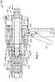
- FIGS. 2 and 3are a cross section of the rapid-connect coupler 100 in a first and second configuration respectively, in accordance with the embodiment of FIG. 1 which generally comprises a first architecture 110 and a second architecture 120 , which are operable to move relative to each other along a central axis X.
- the first architecture 110comprises a sleeve 205 , one or more drive pin 210 , and a probe assembly 215 , which includes a coupling end 220 .
- the one or more drive pin 210extends though a respective drive slot 140 defined by a portion of the second architecture 120 .
- the second architecture 120comprises a ball cage 225 , which defines a coupling orifice 230 and includes one or more ball 245 .
- a female poppet assembly 235which is biased by a poppet assembly spring 280
- the female poppet assembly 235further comprises a retainer 240 , and seal assembly 260 .
- the second architecture 120further comprises one or more guide pins 250 , and a housing barrel 255 .
- the one or more guide pins 250may be operable to provide a positive guide the second architecture 120 about the female poppet assembly 235 .
- the second architecture 120 or portions thereofmay be removable, and may be configured for easy and swift removal and replacement, which may be required due to damage or maintenance needs.
- the first and second handle 130 A, 130 Bare rotatably coupled to the housing barrel 255 , via a first and second barrel flange 270 A, 270 B respectively. Additionally, a first and second link assembly 275 A, 275 B are rotatably attached to the first and second handle 130 A, 130 B respectively. A first and second link assembly 275 A, 275 B are rotatably attached to the probe assembly 215 .
- the first and second handle 130 A, 130 Bare operable to rotate about the first and second barrel flange 270 A, 270 B respectively over a range of motion including configurations A, B, and C, which are depicted in FIG. 2 .
- FIG. 3depicts the rapid-connect coupler 100 in configuration B.
- these configurationsmay be a de-coupled configuration A, a coupled configuration B, and a semi-coupled configuration C.
- the first and second handle 130 A, 130 Brotate between the A and B configurations, for example, the first architecture 110 and a second architecture 120 move relative to each other along the central axis X.
- the probe assembly 215translates within the housing barrel 255 , and is biased by a probe spring 265 .
- the ball cage 225is operable to translate within the sleeve 205 .
- FIG. 2depicts the ball cage 225 extending substantially past the sleeve 205
- FIG. 3depicts the ball cage 225 extending only partially past the sleeve 205 .
- FIG. 2depicts the ball cage 225 extending substantially past the female poppet assembly 235
- FIG. 3depicts the ball cage 225 extending only partially past the female poppet assembly 235
- the volume of the coupling orifice 230is depicted as being greater in FIG. 2 compared to FIG. 3
- the ball cage 225 and sleeve 205may define a portion of the coupling head 101 .
- the sleeve 205may have a greater diameter than the probe assembly 215 and be coupled thereto via one or more driving pins 210 , which extend through slots 140 ( FIG. 1 ) in the housing barrel 120 .
- the probe assembly 215may be slidably disposed within the housing barrel 120 , and therefore the probe assembly 215 may have a smaller diameter than the housing barrel 120 and may have a smaller diameter than the sleeve 205 .
- the ball cage 225may have a greater diameter than the housing barrel 255 and be coupled thereto via guide pins 250 .
- Such a configurationmay be desirable because user exposure to moving parts and pinch-points may be reduced in addition to allowing for a reduced profile of the coupler 100 .
- the housing barrel 255may cover moving parts associated with the probe assembly.
- the rapid-connect coupler 100is operable to couple with a male fueling receptacle 500 .
- the rapid-connect coupler 100is placed on the male fueling receptacle 500 while in configuration A, and then transitioned into configuration B, to lock the rapid-connect coupler 100 on the male fueling receptacle 500 , and then returned to configuration A to release the rapid-connect coupler 100 from the male fueling receptacle 500 .
- gase.g. liquid natural gas
- ventingmay occur as the poppets 540 , 235 disengage.
- the rapid-connect coupler 100may be operable to generate a positive stop, which allows the rapid-connect coupler 100 to vent before it is fully disengaged from the male fueling receptacle 500 . Venting before fully disengaging may be desirable because force generated by venting fluid could cause the coupler 100 to recoil and harm an operator if the coupler 100 did not remain coupled to the receptacle 500 to absorb the force and prevent recoil of the coupler 100 .
- the rapid-connect coupler 100may be operable to generate a positive stop of the handles 130 A, 130 B at configuration C, which may allow the rapid-connect coupler 100 to vent while in configuration C before returning to configuration A, where the rapid-connect coupler 100 may be released from the male fueling receptacle 500 . Accordingly, in an embodiment, the rapid-connect coupler 100 may remain substantially coupled to the male fueling receptacle 500 while in configuration C, but allow the rapid-connect coupler 100 to vent.
- the rapid-connect coupler 100may be operable to generate a positive stop via a vent-stop 400 ( FIGS. 1 and 4 ).
- the vent-stop 400may comprise a stop housing 410 , in which holds a stop pin 415 .
- the stop pin 415may be operable to generate a positive stop at configuration C, and the rapid-connect coupler 100 may then be allowed to take configuration A by depressing stop lever 420 , which is biased by a stop spring 425 .
- the vent-stop 400may be operable to arrest translation of the probe assembly 215 within the housing barrel 255 at configuration C.
- FIG. 4also depicts a plurality of guide pins that extend through the housing barrel 255 that are configured to guide and stabilize the probe assembly 215 within the housing barrel 255 .
- guide pinsmay be desirable because they may provide for simple maintenance and alignment of the probe assembly 215 .
- the rapid-connect coupler 100may be operable to move from configuration A to configuration B, without a positive stop at configuration C, but be operable to have a positive stop at configuration C when moving from configuration B to configuration A.
- a positive stopmay occur when moving from configuration B to configuration A and vice versa.
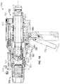
- FIG. 5is a cross section of a rapid-connect coupler 100 and a male fueling receptacle 500 in accordance with an embodiment, which are aligned at a central axis X.
- the male fueling receptacle 500comprises a male coupling body 510 , which includes a lip 520 , and a recess 525 behind the lip 520 .
- the male coupling body 510defines a male poppet orifice 530 .
- a male poppet assembly 540is disposed within the poppet orifice 530 .
- the rapid-connect coupler 100may be operable to couple with the male fueling receptacle 500 .
- the rapid-connect coupler 100may be placed on the male fueling receptacle 500 while in configuration A, put into configuration B to lock the rapid-connect coupler 100 on the male fueling receptacle 500 , and then returned to configuration A to release the rapid-connect coupler 100 from the male fueling receptacle 500 .
- the male coupling body 510is operable to be slidably received within the female coupling orifice 230
- the female poppet assembly 235is operable to be slidably received within the male poppet orifice 530 such that the female poppet assembly 235 bears against the male poppet assembly 540 .
- the lip 520is operable to push the one or more balls 245 outward, and thereby allow the lip 520 to pass past the balls 245 .
- the balls 245may then be able to fall into or be forced into the recess 525 behind the lip 520 .
- the rapid-connect coupler 100may then move to configuration B as shown in FIG. 3 , which causes the sleeve 205 to slide over the balls 245 , which pushes the balls 245 into the recess 525 behind the lip 520 and then locks the balls 245 in a position wherein the balls 245 extend into the female coupling orifice 230 in the recess 525 of the male coupling body 510 . Accordingly, the male coupling body 510 may locked within the female coupling orifice 230 .
- the male and female poppet 540 , 235may be operable to allow fluid (e.g., liquid natural gas) to pass from the rapid-connect coupler 100 into male coupling body 510 .
- the sealing assembly 260may be operable to provide a seal by bearing against the interior surface of the male coupling body 510 within the male poppet orifice 530 .
- the sealing assembly 260may be a two piece seal with an energizing spring.
- the coupled rapid-connect coupler 100 and male coupling body 510may be allowed to vent by moving the rapid-connect coupler 100 to configuration C ( FIG. 2 ), which may retract the sleeve 205 such that the balls 245 are able to partially retract and allow the male and female poppet 540 , 235 to disengage, and allow remaining gas from the connection to escape, while still locking the male coupling body 510 within the female coupling orifice 230 via the balls 245 partially residing within the recess 525 .
- a usermay actuate the vent stop 400 to allow the sleeve 205 to fully retract, and thereby allow the balls 245 to movably reside within the sleeve 205 such that the lip 520 of the male coupling body 510 is allowed to pass past the balls 245 , and thereby allows the male coupling body 510 to leave the female coupling orifice 230 .
- balls 245 within the sleeve 205may be desirable.
- the balls 245allow the male coupling body 510 to be guided and rolled into the female coupling orifice 230 ; the spherical shape of the balls 245 prevents catching of the male coupling body 510 as it passed the balls 245 ; and the balls 245 tend to release ice more efficiently, which forms when cold temperatures are present (e.g., when using a cooled gas such as liquid natural gas or in cold environmental conditions).
- tapered slots 610 A, 610 Bmay be concave toward the external and internal portions of the ball cage 225 .
- Tapered slots 610 A, 610 Bmay be desirable because the tapered slots 610 A, 610 B tend to release ice more efficiently, which may form within the tapered slots 610 A, 610 B when cold temperatures are present (e.g., when using a cooled gas such as liquid natural gas or in cold environmental conditions).
- the tapered walls 620 A, 620 Bmay be various configurations and types of tapers, including linear tapers or curved tapers, and the entirety of the tapered slots 610 A, 610 B may or may not include a taper.
- FIGS. 7 a and 7 bare a front and side view of a rapid-connect coupler 700 in accordance with another embodiment.
- FIG. 8is a cross section of the rapid-connect coupler 700 .
- FIGS. 9-11depict the rapid-connect coupler 700 coupling with a receptacle 500 in a first, second and third configuration respectively.
- the rapid-connect coupler 700generally comprises a first architecture 710 and a second architecture 720 , which are operable to move relative to each other along a central axis X.
- the first architecture 710comprises a sleeve 805 , one or more drive assembly 810 , and a probe assembly 815 , which includes a coupling end 820 .
- Portions of the first and second architecture 710 , 720define a coupling head 701 and a coupler body 702 .
- the second architecture 720comprises a cage 725 , which defines a coupling orifice 830 .
- a female poppet assembly 835resides within the coupling orifice 830 .
- the second architecture 120 or portions thereofmay be removable, and may be configured for easy and swift removal and replacement, which may be required due to damage or maintenance needs.
- the ball cage 725 and sleeve 825may define a portion of the coupling head 701 .
- One or more handle 740may be coupled to the second architecture 720 , which is configured to move the sleeve 825 and poppet assembly 815 via a trigger 730 , link assembly 885 , and link bar 890 .
- the coupler 700is configured to move over a range of motion including configurations, 2 B, 2 C and 2 A which are depicted in FIGS. 9, 10 and 11 respectively. In some embodiments, these configurations may be a de-coupled configuration 2 A, a coupled configuration 2 B, and a semi-coupled configuration 2 C.
- FIG. 9depicts the coupler 700 coupled to a receptacle 500 wherein complementary poppets 540 , 835 engage to allow fluid to flow or communicate between the receptacle 500 and the coupler 700 .
- the coupler 700couples with the receptacle 500 by a biased latch 845 hooking with a complementary lip 520 on the receptacle 500 .
- the latch 845is held in place by the sleeve 805 , which moves forward from a de-coupled position 2 A to the coupled position 2 B.
- FIG. 10depicts the coupler in a semi-coupled position 2 C, wherein the sleeve 805 partially retracts along with the poppet 835 and probe assembly 815 .
- the sleeve 805holds the latch 845 down such that the latch 545 remains hooked with the lip 520 and the coupler 700 remains coupled with the receptacle 500 .
- the disengaged poppets 540 , 835prevent fluid from flowing or communicating between or from the coupler 700 and receptacle 500 .
- the poppets 540 , 835disengage as the coupler 700 moves from coupled configuration 2 B to semi-coupled configuration 2 C, fluid may be released.
- the venting fluidmay generate a repulsive force between the coupler 700 and the receptacle 500 , which may be opposed by the connection between the coupler 700 and the receptacle 500 .
- Thismay be desirable in various embodiments because the coupler 700 is allowed to safely vent before de-coupling from the receptacle 500 , which may prevent injury to an operator as the coupler 700 recoils when the poppets 540 , 835 disengage.
- the coupler 700may the move from semi-coupled configuration 2 C to de-coupled configuration 2 A as depicted in FIG. 11 .
- the sleeve 805further retracts, which causes the latch 845 to rotate upward and away from the receptacle 500 .
- the latch 845thereby disengages from the lip 520 , which allows the coupler 700 to disengage and de-couple from the receptacle 500 .
- the coupler 700may then be coupled to the receptacle 500 by positioning the coupling orifice 830 over the receptacle 500 .
- the coupler 700may be configured by the trigger 730 and transitioned between the de-coupled, coupled and semi-coupled configurations 2 A, 2 B, 2 C.
- the trigger 730may be depressed so that the coupler 700 takes the de-coupled position 2 A as depicted in FIG. 11 .
- the coupler 700may then be positioned on the receptacle 500 and the trigger 730 may be released so that the sleeve 805 slides over the latch 845 , which rotates the latch 845 down to engage the lip 520 , which couples the coupler 700 and the receptacle 500 .
- the coupler 700is then in the coupled position 2 B. Positioning the coupler 700 over the receptacle 500 causes the poppets 540 , 835 to engage and allow fluid to flow between the coupler 700 and the receptacle 500 .
- the trigger 730may then be partially depressed so that the coupler 700 transitions to the semi-coupled configuration 2 C.
- a hard-stopis generated as the coupler 700 transitions from the coupled configuration 2 B to the semi-coupled configuration 2 C, which provides time for the coupler 700 to vent before the coupler 700 transitions to the de-coupled position 2 A.
- the hard-stopmay be generated by a stop-apparatus 400 or other apparatus.
- one or more of the trigger 730 , link assembly 885 , and link bar 890may be configured to provide a hard-stop. The hard-stop may be released and the coupler 700 may then be transitioned from the semi-coupled configuration 2 C to the de-coupled position 2 A.
- FIG. 12 ais a side view of a rapid-connect coupler 1200 in accordance with another embodiment
- FIG. 12 bis a rear view of the rapid-connect coupler 1200
- FIG. 13 ais a cross section of the rapid-connect coupler 1200 .
- the rapid-connect coupler 1200generally comprises a first architecture 1210 and a second architecture 1220 , which are operable to move relative to each other along a central axis X.
- the first architecture 1210comprises a sleeve 1205 , one or more drive pin 1310 , and a probe assembly 1315 , which includes a coupling end 1220 .
- Portions of the first and second architecture 1210 , 1220define a coupling head 1201 and a coupler body 1202 .
- the second architecture 1220comprises a ball cage 1225 , which defines a coupling orifice 1330 .
- a female poppet assembly 1335resides within the coupling orifice 1330 .
- the second architecture 1220 or portions thereofmay be removable, and may be configured for easy and swift removal and replacement, which may be required due to damage or maintenance needs.
- the ball cage 1225 and sleeve 1205may define a portion of the coupling head 1201 .
- a pneumatic actuating handle assembly 1230may be coupled to the second architecture 720 , which is configured to move the first architecture 1210 relative to the second architecture 1220 .
- the actuating handle assembly 1230may be connected to the probe assembly 1315 by actuating connections 1385 A, 1385 B, which allows the probe assembly 1230 and sleeve 1305 to be slidably configured relative to the ball cage 1325 and housing 1255 .
- the coupler 1200may therefore be configured to move over a range of motion including configurations which may be analogous to configurations A, B and C which are depicted in FIGS. 2 and 3 .
- the actuating grip 1275may be rotated between a first and second position, which causes the pneumatic actuating handle assembly 1230 to move the first and second architectures 1210 , 1220 toward or away from each other.
- coupler 1200may be in a de-coupled configuration as depicted in FIG. 13 a , (which may be analogous to configurations A, 2 A).
- the actuating grip 1275may be rotated to a second position and the sleeve 1305 may slide forward over balls 1345 disposed within the ball cage 1325 . This may lock the balls 1345 in a position which is operable to couple the coupler 1200 to a receptacle 500 as described herein.
- Complementary poppets 1335 , 540 in a receptacle 500 and the coupler 1200may engage and allow fluid to flow between the receptacle 500 and the coupler 1200 as described herein.
- the coupler 1200may then be in a coupled position, (which may be analogous to configurations B, 2 B).
- the actuating grip 1275may be rotated back toward or to the first position which causes the sleeve 1305 and poppet 1335 to move backward toward the rear of the coupler 1200 .
- a hard-stopmay be generated, which stops the translation of the probe assembly 1315 within the housing 1255 .
- a stop handle 1240may extend within the housing 1255 and be rotatably biased via a pin 1246 and a handle-spring 1248 .
- the stop handle 1240may further include a stop head 1242 which is configured to engage with a probe notch 1244 .
- the stop handle 1240may be configured to allow the coupler 1200 to move from the de-coupled position to the coupled position without obstruction; however, as the coupler 1200 moves from the coupled position back toward the de-coupled position, the stop head 1242 may engage the probe notch 1244 and thereby create a hard-stop in a semi-coupled position (which may be analogous to configurations C, 2 C).
- a semi-coupled configurationmay be a configuration, where the coupler 1200 is configured to remain coupled to a receptacle 500 as complementary poppets 1335 , 540 in the receptacle 500 and the coupler 1200 disengage. Recoil of the coupler 1200 caused by the discharge of fluid between the poppets 1335 , 540 , may be absorbed by the sustained coupling of the coupler 1200 and receptacle 500 .
- the hard-stopmay be disengaged by pulling on the stop handle 1240 to rotate the stop head 1242 out of the probe notch 1244 .
- the coupler 1200may then transition into the de-coupled position. Transitioning of the coupler 1200 into the de-coupled position may occur once the hard-stop is released or may be achieved by rotating the actuating grip 1275 .
- Various embodiments discussed hereininclude elements or structures which are configured to provide a hard-stop in coupler 100 , 700 , 1200 . Further embodiments, and the embodiments discussed herein may include various alternative structures or elements operable to provide a hard-stop.
- a hard-stopmay be achieved via one or more of a hook, hole, slot, shoulder, latch, brake, or the like.
- Such structures or elementsmay be internal or externally located and may generate a hard-stop which may be released in various ways.
- a hard-stopmay be released by a user actuating a handle, switch, button or the like.
- a hard-stopmay be released by a timer, which may be electronic or mechanical.
- a hard-stopmay be automatically released or prevented from being released until defined conditions are present. For example, a hard-stop may be maintained until fluid venting has ceased. Sensors, electronic or mechanical, may determine whether fluid venting has ceased.
- a couplingmay be achieved via one or more of a hook, hole, slot, shoulder, latch, brake, or the like.
- a coupler 100 , 700 , 1200are disclosed herein as being configured to couple with receptacle 500 , various embodiments may be adapted to coupled with a receptacle having other configurations. For example, various embodiments may relate to coupling with male and female receptacles and receptacles having holes, slots, lips, shoulders or threads both internally or externally.
Landscapes
- Engineering & Computer Science (AREA)
- General Engineering & Computer Science (AREA)
- Mechanical Engineering (AREA)
- Quick-Acting Or Multi-Walled Pipe Joints (AREA)
Abstract
Description
Claims (19)
Priority Applications (1)
| Application Number | Priority Date | Filing Date | Title |
|---|---|---|---|
| US15/849,188US10718456B2 (en) | 2011-03-21 | 2017-12-20 | Rapid-connect coupler with vent-stop |
Applications Claiming Priority (4)
| Application Number | Priority Date | Filing Date | Title |
|---|---|---|---|
| US201161454696P | 2011-03-21 | 2011-03-21 | |
| US13/426,377US9194524B2 (en) | 2011-03-21 | 2012-03-21 | Rapid-connect coupler with vent-stop |
| US14/928,456US9857010B2 (en) | 2011-03-21 | 2015-10-30 | Rapid-connect coupler with vent-stop |
| US15/849,188US10718456B2 (en) | 2011-03-21 | 2017-12-20 | Rapid-connect coupler with vent-stop |
Related Parent Applications (1)
| Application Number | Title | Priority Date | Filing Date |
|---|---|---|---|
| US14/928,456DivisionUS9857010B2 (en) | 2011-03-21 | 2015-10-30 | Rapid-connect coupler with vent-stop |
Publications (2)
| Publication Number | Publication Date |
|---|---|
| US20180156371A1 US20180156371A1 (en) | 2018-06-07 |
| US10718456B2true US10718456B2 (en) | 2020-07-21 |
Family
ID=46880021
Family Applications (3)
| Application Number | Title | Priority Date | Filing Date |
|---|---|---|---|
| US13/426,377Active2033-03-31US9194524B2 (en) | 2011-03-21 | 2012-03-21 | Rapid-connect coupler with vent-stop |
| US14/928,456ActiveUS9857010B2 (en) | 2011-03-21 | 2015-10-30 | Rapid-connect coupler with vent-stop |
| US15/849,188Active2032-05-30US10718456B2 (en) | 2011-03-21 | 2017-12-20 | Rapid-connect coupler with vent-stop |
Family Applications Before (2)
| Application Number | Title | Priority Date | Filing Date |
|---|---|---|---|
| US13/426,377Active2033-03-31US9194524B2 (en) | 2011-03-21 | 2012-03-21 | Rapid-connect coupler with vent-stop |
| US14/928,456ActiveUS9857010B2 (en) | 2011-03-21 | 2015-10-30 | Rapid-connect coupler with vent-stop |
Country Status (5)
| Country | Link |
|---|---|
| US (3) | US9194524B2 (en) |
| EP (3) | EP3511603B1 (en) |
| CN (2) | CN103547848B (en) |
| ES (3) | ES2719851T3 (en) |
| WO (1) | WO2012129340A2 (en) |
Cited By (1)
| Publication number | Priority date | Publication date | Assignee | Title |
|---|---|---|---|---|
| US20240084940A1 (en)* | 2021-05-28 | 2024-03-14 | Engineered Controls International, Llc | Low-emission nozzle and receptacle coupling for cryogenic fluid |
Families Citing this family (18)
| Publication number | Priority date | Publication date | Assignee | Title |
|---|---|---|---|---|
| US9194524B2 (en)* | 2011-03-21 | 2015-11-24 | Engineered Controls International, Llc | Rapid-connect coupler with vent-stop |
| US9114815B2 (en) | 2013-03-14 | 2015-08-25 | Brandt Road Rail Corporation | Assembly for extendable rail-supported vehicle coupler |
| WO2014153079A1 (en)* | 2013-03-14 | 2014-09-25 | Macro Technologies, Llc | Rapid-connect coupler with vent-holes |
| CN110594520B (en)* | 2015-04-27 | 2021-03-30 | 国际工程控制公司 | fluid coupler |
| CN105156816B (en)* | 2015-10-09 | 2017-05-03 | 河南城建学院 | Mechanical quick shut-off valve |
| EP4471321A3 (en) | 2015-12-03 | 2025-03-19 | Engineered Controls International, LLC | Leak resistant and serviceable receptacle |
| ES2965302T3 (en)* | 2015-12-03 | 2024-04-12 | Engineered Controls Int Llc | Low Emission Nozzles and Receptacles |
| US10876636B2 (en) | 2015-12-03 | 2020-12-29 | Engineered Controls International, Llc | Leak resistant and serviceable receptacle |
| GB2549287B (en)* | 2016-04-11 | 2019-07-24 | Self Energising Coupling Co Ltd | Fluid coupling with cam and follower controlled securing means |
| US11912213B2 (en)* | 2018-05-01 | 2024-02-27 | Thetford Bv | Discharge device for vehicle wastewater management system |
| ES2900356T3 (en) | 2018-05-22 | 2022-03-16 | Engineered Controls Int Llc | Replaceable, leak-resistant receptacle |
| US11460136B2 (en) | 2019-04-05 | 2022-10-04 | Engineered Controls International, Llc | Rapid-connect coupler and receptacle having anti-rotation feature |
| CN110500463B (en)* | 2019-07-17 | 2021-08-20 | 华为技术有限公司 | A joint, cooling system and computer device |
| EP4028686A1 (en)* | 2019-09-09 | 2022-07-20 | Engineered Controls International, LLC | Coupling nozzle for cryogenic fluid |
| US11193807B2 (en)* | 2020-02-10 | 2021-12-07 | Toyota Motor Engineering & Manufacturing North America, Inc. | Pneumatic probe |
| DE102020205694A1 (en)* | 2020-05-06 | 2021-11-11 | Robert Bosch Gesellschaft mit beschränkter Haftung | Quick coupler with side operating levers |
| US20230408036A1 (en)* | 2020-10-02 | 2023-12-21 | Linde Gmbh | Method for operating a cryogenic refueling arrangement |
| AU2021351105A1 (en)* | 2020-10-02 | 2023-06-08 | Butting Cryo Tech Gmbh | Cryogenic tank filling arrangement and method |
Citations (168)
| Publication number | Priority date | Publication date | Assignee | Title |
|---|---|---|---|---|
| US430721A (en) | 1890-06-24 | Hose-coupling | ||
| US2070013A (en) | 1935-04-29 | 1937-02-09 | Min A Max Co Inc | Lubricating apparatus |
| US2259137A (en) | 1939-08-14 | 1941-10-14 | Sr William C Iftiger | Coupling |
| US2323099A (en) | 1941-12-05 | 1943-06-29 | Patten Walter Evans | Tube fitting |
| US2327714A (en) | 1940-06-04 | 1943-08-24 | Sr William C Iftiger | Coupling |
| US2388179A (en) | 1943-02-06 | 1945-10-30 | Prowd William Thomas | Pipe coupling |
| US2434167A (en) | 1945-05-23 | 1948-01-06 | Ernest O Knoblauch | Valved coupling |
| US2512320A (en) | 1946-02-05 | 1950-06-20 | Frederick C Fischer | Valve |
| US2519358A (en) | 1947-06-12 | 1950-08-22 | Parker Appliance Co | Nozzle attachment for tanks |
| US2552543A (en) | 1950-04-03 | 1951-05-15 | Clarence E Earle | Coupling |
| US2675829A (en) | 1951-06-22 | 1954-04-20 | Bendix Aviat Corp | Quick-disconnect coupling with selectively operable valve |
| US2797110A (en) | 1956-04-04 | 1957-06-25 | Carl A Covington | Ball detent coupling |
| US2806741A (en) | 1954-05-26 | 1957-09-17 | Akron Brass Mfg Company Inc | Hose nozzle |
| US2858146A (en) | 1956-02-02 | 1958-10-28 | Jr Gustave A Bleyle | Coupling means for liquified-gas conduits |
| US2904351A (en) | 1956-01-31 | 1959-09-15 | Flight Refueling Inc | Pipe-coupling devices |
| US3069127A (en) | 1957-12-12 | 1962-12-18 | Flight Refueling Inc | Pipe couplings |
| US3217747A (en) | 1960-06-27 | 1965-11-16 | Cla Val Co | Hydrant valve |
| US3311128A (en) | 1964-02-25 | 1967-03-28 | Daniel Orifice Fitting Company | Butterfly valve |
| US3367366A (en) | 1965-10-11 | 1968-02-06 | Universal Oil Prod Co | Disconnect with minimum inclusion |
| US3472482A (en) | 1966-06-10 | 1969-10-14 | Parker Hannifin Corp | Fueling nozzle |
| US3474827A (en) | 1966-02-09 | 1969-10-28 | Emco Wheaton | Coupler and adapter and seal structure therefor |
| US3583667A (en) | 1969-07-16 | 1971-06-08 | William T Amneus Jr | Quick-disconnect coupling |
| US3589673A (en) | 1968-06-20 | 1971-06-29 | Foster Mfg Co Inc | Fluid line coupling |
| FR2063957A1 (en) | 1969-10-10 | 1971-07-16 | Marie Jean | |
| US3664634A (en) | 1968-09-19 | 1972-05-23 | Robert W Guertin | Valve seal for coupling device |
| US3674051A (en) | 1971-05-14 | 1972-07-04 | Safe Way Hydraulics | Hydraulic coupler |
| US3680591A (en) | 1970-05-07 | 1972-08-01 | Dempco | Unique hydraulic coupler |
| US3710823A (en) | 1971-01-25 | 1973-01-16 | Dempco | Hydraulic coupler with cam actuator |
| US3757836A (en) | 1971-02-03 | 1973-09-11 | Daido Kogyo K Ltd | Quick-connect valve for use in filling gas cylinders |
| US3809122A (en) | 1972-11-02 | 1974-05-07 | Allis Chalmers | Hydraulic coupling |
| US3897091A (en) | 1972-06-08 | 1975-07-29 | Dover Corp | Dry-break coupler |
| US3913844A (en) | 1974-03-13 | 1975-10-21 | Graco Inc | Safety spray gun trigger |
| US3924654A (en) | 1973-12-26 | 1975-12-09 | Hughes Aircraft Co | Quick disconnect tank coupler |
| US4124228A (en) | 1977-03-24 | 1978-11-07 | Kaiser Aerospace & Electronics Corporation | Pressure-balanced fluid coupling |
| US4181143A (en) | 1977-09-28 | 1980-01-01 | Draft Systems, Inc. | Valve assembly and coupler therefor |
| US4181150A (en) | 1977-09-12 | 1980-01-01 | Gould, Inc. | Lever-type quick disconnect coupling |
| WO1980001711A1 (en) | 1979-02-08 | 1980-08-21 | L Berg | Quick coupling device for pressurized fluid conduits |
| US4234161A (en) | 1978-12-06 | 1980-11-18 | Dover Corporation | Linkage assembly for a coupler |
| US4235258A (en) | 1978-01-03 | 1980-11-25 | Tomoe Technical Research Company | Driving device for opening and closing a valve |
| US4260130A (en) | 1979-07-30 | 1981-04-07 | B & G Equipment Company | Valve for corrosive fluids |
| EP0039977A1 (en) | 1980-05-09 | 1981-11-18 | Nederlandse Organisatie voor toegepast-natuurwetenschappelijk onderzoek TNO | Loading device, especially for LPG |
| US4303098A (en) | 1980-04-14 | 1981-12-01 | Deere & Company | Female coupler |
| US4347870A (en) | 1980-05-14 | 1982-09-07 | Gould Inc. | Lever-type quick disconnect coupling |
| US4366945A (en) | 1978-12-20 | 1983-01-04 | Abnox Ag | Hose coupling with double lock |
| US4398561A (en) | 1981-03-27 | 1983-08-16 | Imperial Clevite Inc. | Quick disconnect coupling with locked valving |
| US4437647A (en) | 1979-12-17 | 1984-03-20 | Foster Manufacturing Company | Quick connect-disconnect coupling for fluid lines |
| US4541457A (en) | 1982-03-17 | 1985-09-17 | Colder Products Company | Two-way uncoupling valve assembly |
| US4543995A (en) | 1982-12-23 | 1985-10-01 | Erwin Weh | Pipe coupling having line pressure actuated threaded segments |
| US4552333A (en) | 1984-01-27 | 1985-11-12 | Oy Pajakanta Ab | Bayonet catch for a line of pressurized medium |
| US4567924A (en) | 1983-02-25 | 1986-02-04 | Brown Albert W | Aircraft under-wing fueling nozzle system |
| US4664148A (en) | 1986-02-03 | 1987-05-12 | Clevite Industries Inc. | Quick disconnect coupling with a lockable valve actuator |
| US4676269A (en) | 1986-03-07 | 1987-06-30 | Tuthill Corporation | Connector assembly |
| US4716938A (en) | 1985-05-20 | 1988-01-05 | Erwin Weh | Pressure-tight plug coupling |
| US4726390A (en) | 1986-03-26 | 1988-02-23 | Waltec, Inc. | Hose bibb vacuum breaker |
| EP0296282A1 (en) | 1987-06-22 | 1988-12-28 | Harischandra Kesrinath Mhatre | A gas pressure regulator with inter-lockable latching means |
| US4799512A (en) | 1987-11-12 | 1989-01-24 | Tuthill Corporation | Coupling assembly |
| US4881573A (en) | 1989-01-31 | 1989-11-21 | Deere & Company | Female hydraulic coupler with push-connect and lever disconnect |
| US4884830A (en) | 1988-01-19 | 1989-12-05 | Fastest, Inc. | Quick connect coupling device |
| US4921282A (en) | 1984-02-16 | 1990-05-01 | Fastest Incorporated | Undermoderated nuclear reactor |
| US5002254A (en) | 1988-12-19 | 1991-03-26 | Legris S.A. | Automatic coupler for pressurized fluid circuit |
| US5046523A (en) | 1989-06-02 | 1991-09-10 | George Horhota | Lock core service valve |
| US5074332A (en) | 1990-08-16 | 1991-12-24 | Production Control Units, Inc. | Hose coupling unit for refrigerant system |
| US5080132A (en) | 1989-04-06 | 1992-01-14 | Kent-Moore Corporation | Refrigeration equipment service apparatus with quick-disconnect couplings |
| US5092364A (en) | 1991-06-20 | 1992-03-03 | Perfecting Services, Inc. | Quick-action fluid coupling |
| US5127428A (en) | 1985-12-24 | 1992-07-07 | Dover Corporation | Poppet valve assembly and method of making same |
| US5129621A (en) | 1990-11-28 | 1992-07-14 | Aeroquip Corporation | Dry break coupling |
| US5139049A (en) | 1990-11-15 | 1992-08-18 | Aeroquip Corporation | Refrigeration system service adapter |
| US5161568A (en) | 1991-08-14 | 1992-11-10 | Keen Manufacturing, Inc. | Safety lockout valve and coupling |
| US5205317A (en) | 1991-09-12 | 1993-04-27 | Delta Industrial Valves, Inc. | Valve assembly |
| US5211197A (en) | 1992-01-03 | 1993-05-18 | Aeroquip Corporation | Quick disconnect liquid line coupling with volumertric expansion couping element |
| US5255714A (en) | 1992-11-13 | 1993-10-26 | Perfecting Services, Inc. | Quick-action fluid coupling |
| US5265844A (en) | 1992-11-02 | 1993-11-30 | Westfall Randell W | Receptacle valve assembly and seal |
| WO1993025838A1 (en) | 1992-06-11 | 1993-12-23 | Parker-Hannifin Corporation | Coupling device |
| US5289850A (en) | 1992-06-08 | 1994-03-01 | Tuthill Corporation | Fluid coupling having vent valve assembly |
| US5290009A (en) | 1991-10-08 | 1994-03-01 | Rectus-Apparatebau, Walker Klein Gmbh | Self-venting, rapid connection-release coupling for compressed gas lines, for example compressed air lines |
| US5293902A (en) | 1993-06-07 | 1994-03-15 | Tif Instruments, Inc. | Quick-disconnect fluid coupling |
| US5301723A (en) | 1992-11-06 | 1994-04-12 | Hydra Rig, Inc. | Apparatus and method of preventing ice accumulation on coupling valves for cryogenic fluids |
| US5339862A (en) | 1993-07-29 | 1994-08-23 | Aeroquip Corporation | Refrigeration system service adapter |
| US5363879A (en) | 1994-02-15 | 1994-11-15 | Liquid Carbonic Corporation | Cryogenic coupling |
| US5413309A (en) | 1992-12-07 | 1995-05-09 | Parker-Hannifin Corporation | Push-to-connect coupler with interlocking three-way valve |
| US5429155A (en) | 1993-05-19 | 1995-07-04 | Moog Inc. | Cryogenic fluid coupling |
| US5439258A (en) | 1993-08-17 | 1995-08-08 | Production Control Units, Inc. | Tube coupling unit |
| US5445358A (en) | 1994-12-16 | 1995-08-29 | Parker-Hannifin Corporation | Exhaust type quick action coupler |
| US5507530A (en) | 1995-05-08 | 1996-04-16 | Soo Tractor Sweeprake Company | Plural male and female fluid coupler connecting mechanism and method |
| US5535985A (en) | 1994-04-21 | 1996-07-16 | Societe Y.T.O. | Quick coupling for pressure conduit with controlled disengagement |
| CA2166844A1 (en) | 1995-01-16 | 1996-07-17 | Jean-Jacques Lacroix | Improvements in quick connections |
| US5547166A (en) | 1992-10-16 | 1996-08-20 | Engdahl; Bj+E,Uml O+Ee Rn | Hose coupling for compressed air |
| US5564471A (en) | 1995-01-23 | 1996-10-15 | Dover Corporation | Fuel hose breakaway unit |
| US5575510A (en) | 1992-03-31 | 1996-11-19 | Weh Fmbh, Verbindungstechnik | Quick-connect fitting for gas cylinders |
| US5577706A (en) | 1995-10-25 | 1996-11-26 | King; Robert J. | Water faucet with automatic shut-off mechanism for water conservation |
| US5580099A (en) | 1995-04-03 | 1996-12-03 | Eaton; Edward M. | Quick connect/disconnect coupling |
| US5603353A (en) | 1995-11-17 | 1997-02-18 | Essman Screw Products, Inc. | Quick disconnect coupling |
| US5622201A (en) | 1996-02-28 | 1997-04-22 | Chang; King | Bucket valve with removable handle |
| US5649723A (en) | 1993-09-20 | 1997-07-22 | Aga Aktiebolag | Coupling device |
| US5671777A (en) | 1995-07-17 | 1997-09-30 | Dover Corporation | Couplings for joining fluid conduits |
| US5706967A (en) | 1994-06-20 | 1998-01-13 | Weh Gmbh, Verbindung Technik | Safety lock, especially for vehicle fuel tanks |
| US5709243A (en) | 1995-11-20 | 1998-01-20 | Aeroquip Corporation | Low spill female coupling |
| US5788443A (en) | 1997-03-13 | 1998-08-04 | Thread Technology, Inc. | Male coupling with movable threaded segments |
| US5806832A (en) | 1995-10-20 | 1998-09-15 | Societe Y.T.O. | Quick coupler that uncouples in two stages |
| CN2293698Y (en) | 1997-06-18 | 1998-10-07 | 吴金堂 | Fast joining device |
| US5884648A (en) | 1997-08-27 | 1999-03-23 | Scholle Corporation | Coupling valve apparatus and method |
| US5896889A (en) | 1997-10-24 | 1999-04-27 | Menard; Orville R. | Quick-set hydraulic coupler |
| US5927683A (en) | 1995-01-19 | 1999-07-27 | Weh Gmbh, Verbindungstechnik | Rapid connection coupling |
| US5937885A (en) | 1995-06-05 | 1999-08-17 | Value Plastics, Inc. | Fluid fitting coupling system |
| US5950679A (en) | 1998-02-10 | 1999-09-14 | Fastest, Inc. | High pressure plug coupling |
| US5967491A (en) | 1997-12-01 | 1999-10-19 | Parker-Hannifin Corporation | Anti-leak quick action coupler |
| US5984265A (en) | 1995-07-14 | 1999-11-16 | Engdahl; Bjoern | Hose coupling |
| US5988697A (en) | 1997-02-28 | 1999-11-23 | Omba S.R.L. | Mechanism for uniting valve parts |
| US6009901A (en)* | 1998-01-16 | 2000-01-04 | Emco Wheaton Dtm, Inc. | Dry disconnect coupling |
| US6035894A (en) | 1996-07-30 | 2000-03-14 | Weh Gmbh Verbindungstechnik | Coupling device for rapid connection |
| US6039303A (en) | 1997-11-25 | 2000-03-21 | Fastest, Inc. | High pressure fluidline connector |
| US6056010A (en) | 1998-07-23 | 2000-05-02 | Aeroquip Corporation | Anti-check low spill fluid coupling |
| US6073974A (en) | 1998-06-04 | 2000-06-13 | Fastest, Inc. | High pressure coupling |
| US6073971A (en) | 1996-02-29 | 2000-06-13 | Weh Gmbh Verbindungstechnik | Fitting arrangement |
| US6082399A (en) | 1996-04-03 | 2000-07-04 | Bo Erik Nyberg | Quick coupling for hoses or pipes for pressure media |
| US6142194A (en) | 1999-03-09 | 2000-11-07 | Cla-Val | Pressure fuel servicing nozzle |
| US6152496A (en) | 1997-11-14 | 2000-11-28 | Nitto Kohki Co., Ltd. | Socket for pipe coupling |
| US6155294A (en) | 1999-04-02 | 2000-12-05 | Emco Wheaton Fleet Fueling, Corp. | Dry disconnect coupling with improved poppet seal |
| US6161578A (en) | 1996-10-09 | 2000-12-19 | Colder Products Company | Low spill high flow quick coupling valve assembly |
| US6202692B1 (en) | 1999-03-30 | 2001-03-20 | Gustav Schumacher | Device for coupling hydraulic lines |
| US6279874B1 (en) | 1996-03-22 | 2001-08-28 | Bo Erik Nyberg | Coupling for hoses or the like |
| US6343630B1 (en) | 1998-05-22 | 2002-02-05 | Delaware Capital Formation, Inc. | High pressure filling nozzle |
| DE19882564C2 (en) | 1997-07-28 | 2002-02-28 | Nitto Kohki Co | pipe coupling |
| US6375152B1 (en) | 1997-05-22 | 2002-04-23 | Weh, Gmbh | Quick-connect coupling |
| EP1199507A2 (en) | 2000-10-20 | 2002-04-24 | Eaton Aeroquip, Inc. | Releasable coupling assembly |
| US6382251B1 (en) | 2000-03-29 | 2002-05-07 | Snap-Tite Technologies, Inc. | Coupling with male half having internal pressure relief |
| US6398268B1 (en) | 1999-03-04 | 2002-06-04 | Nitto Kohki Co., Ltd. | Pipe coupling for female screw |
| US6408880B1 (en) | 1999-03-13 | 2002-06-25 | Carl Kurt Walther Gmbh & Co. Kg | Plug-in coupling for connecting pipelines, hoses or similar |
| US6412828B1 (en) | 1998-12-03 | 2002-07-02 | Staubli Faverges | Quick safety connection for removably joining pipes |
| US6499719B1 (en) | 1999-07-09 | 2002-12-31 | Container Technology, Inc. | Fluid coupling system |
| US6511100B1 (en) | 1998-12-02 | 2003-01-28 | Legris Sa | Ball-bearing coupler |
| US20030085574A1 (en) | 2001-11-06 | 2003-05-08 | Jean-Paul Froment | Quick connection for the removable join of two pipes |
| US6637460B2 (en) | 2002-01-28 | 2003-10-28 | Eaton Corporation | Dual function service coupling |
| WO2003095883A1 (en) | 2002-05-07 | 2003-11-20 | J.C. Carter Japan K.K. | Cryogenic fluid coupling |
| US6705550B2 (en) | 2001-05-22 | 2004-03-16 | Scot P. Bell | Closed circuit fuel nozzle |
| US20040094956A1 (en) | 2002-11-19 | 2004-05-20 | Staubli Faverges | Quick coupler for removably joining two pipes |
| CN1502839A (en) | 2002-11-19 | 2004-06-09 | 施托布利法韦日公司 | Quick coupler for removable joining two pipes |
| US6776187B1 (en) | 2003-03-06 | 2004-08-17 | Parker-Hannifin Corporation | Quick coupling with pressure assist piston |
| US6830070B2 (en) | 2002-07-18 | 2004-12-14 | Nitto Kohki Co., Ltd. | Fluid coupler automatically uncouplable in an emergency |
| US6840276B2 (en) | 2003-01-29 | 2005-01-11 | Snap-Tite Technologies, Inc. | Ventable manifold |
| US6840548B2 (en) | 2002-02-04 | 2005-01-11 | Staubli Faverges | Quick connection for the removable join of pipes |
| CN1608910A (en) | 2003-10-22 | 2005-04-27 | 施托布利法韦日公司 | Liquid fuel filling device for vehicle |
| US6945477B2 (en) | 2002-09-04 | 2005-09-20 | Parker-Hannifin Corporation | Cryogenic coupling device |
| US7040358B2 (en) | 2002-03-19 | 2006-05-09 | Staubli Faverges | Nozzle with safe functioning and filling installation incorporating such a nozzle |
| US7073773B2 (en) | 2001-03-27 | 2006-07-11 | Invacare Corporation | Rapid connection coupling |
| US20070001143A1 (en) | 2005-04-18 | 2007-01-04 | Konishi M Howard | Pressurized fluid coupler with anti-recoil feature and methods |
| US20070235092A1 (en) | 2006-04-06 | 2007-10-11 | Fastest, Inc. | Latching connectors |
| US20080011369A1 (en) | 2004-10-29 | 2008-01-17 | Nitto Kohki Co., Ltd. | Pipe coupling and male coupling member |
| US20080128034A1 (en) | 2006-12-01 | 2008-06-05 | Dixon Valve And Coupling Company | Handle Lever Locking Mechanism for Dry Disconnect Coupler |
| US20080185837A1 (en) | 2007-02-06 | 2008-08-07 | Fastest, Inc. | Quick connect connector with tolerance accommodation |
| US20080265574A1 (en) | 2005-03-02 | 2008-10-30 | Stubi Faverges | Quick Coupling for Joining Together Two Pipes for Conveying a Gas Under Pressure |
| US7469718B2 (en) | 2004-07-27 | 2008-12-30 | Parker-Hannifin Corporation | Quick disconnect cryogenic coupler |
| US7497231B2 (en) | 2004-10-15 | 2009-03-03 | Nitto Kohki Co., Ltd. | Female coupling member of pipe coupling |
| EP2058576A2 (en) | 2007-10-15 | 2009-05-13 | Agramkow Fluid Systems A/S | An adaptor for CO2 systems as well as a method for the use thereof |
| US20090140519A1 (en) | 2007-11-30 | 2009-06-04 | Caterpillar Inc. | Quick connect tubular coupling |
| US20090165870A1 (en) | 2007-09-28 | 2009-07-02 | Macro Technologies, Inc. | Manifold assembly |
| US7568737B2 (en) | 2006-09-22 | 2009-08-04 | Eaton Corporation | Male coupling for connecting to female threaded coupling |
| US20090205722A1 (en) | 2008-02-14 | 2009-08-20 | Sledz Industries Inc. | Load line apparatus |
| US20100024904A1 (en) | 2008-08-01 | 2010-02-04 | Hoffman Alex L | Low emission fluid transfer device |
| US20100127198A1 (en) | 2007-05-23 | 2010-05-27 | Oscar Cozza | Quick-coupling valve, particularly for pressurized fluids |
| US20100148499A1 (en) | 2008-12-12 | 2010-06-17 | Philippe Le Quere | Coupling device fitted with instantaneous or quasi-instantaneous anchor means |
| US7753415B2 (en) | 2004-01-20 | 2010-07-13 | Staubli Faverges | Quick connection and method for uncoupling the male and female elements of such a connection |
| CN101946113A (en) | 2007-12-22 | 2011-01-12 | 欧文.韦 | Adapters especially for LNG |
| US20110186176A1 (en) | 2010-01-29 | 2011-08-04 | Aehle Achim | Hose fuel nozzle |
| WO2012129340A2 (en) | 2011-03-21 | 2012-09-27 | Howard Konishi | Rapid-connect coupler with vent-stop |
| WO2013059748A1 (en) | 2011-10-19 | 2013-04-25 | Robert Charles Cooley | Grease delivery receiver and nozzle having pressurization lockout and bleed-down capture |
| US20140261741A1 (en) | 2013-03-14 | 2014-09-18 | Macro Technologies, Llc | Rapid-connect coupler with vent-holes |
| US9115838B2 (en) | 2010-08-10 | 2015-08-25 | Engineered Controls International, Llc | Rapid-connect coupler |
Family Cites Families (1)
| Publication number | Priority date | Publication date | Assignee | Title |
|---|---|---|---|---|
| JP5318008B2 (en)* | 2010-03-19 | 2013-10-16 | 株式会社大内海洋コンサルタント | Sailing ship |
- 2012
- 2012-03-21USUS13/426,377patent/US9194524B2/enactiveActive
- 2012-03-21EPEP19160487.5Apatent/EP3511603B1/enactiveActive
- 2012-03-21CNCN201280024576.0Apatent/CN103547848B/enactiveActive
- 2012-03-21EPEP12759894.4Apatent/EP2689177B1/enactiveActive
- 2012-03-21ESES12759894Tpatent/ES2719851T3/enactiveActive
- 2012-03-21WOPCT/US2012/030002patent/WO2012129340A2/enactiveApplication Filing
- 2012-03-21ESES19160487Tpatent/ES2983067T3/enactiveActive
- 2012-03-21ESES19160482Tpatent/ES2961816T3/enactiveActive
- 2012-03-21EPEP19160482.6Apatent/EP3511601B1/enactiveActive
- 2012-03-21CNCN201710020065.6Apatent/CN107035930B/enactiveActive
- 2015
- 2015-10-30USUS14/928,456patent/US9857010B2/enactiveActive
- 2017
- 2017-12-20USUS15/849,188patent/US10718456B2/enactiveActive
Patent Citations (180)
| Publication number | Priority date | Publication date | Assignee | Title |
|---|---|---|---|---|
| US430721A (en) | 1890-06-24 | Hose-coupling | ||
| US2070013A (en) | 1935-04-29 | 1937-02-09 | Min A Max Co Inc | Lubricating apparatus |
| US2259137A (en) | 1939-08-14 | 1941-10-14 | Sr William C Iftiger | Coupling |
| US2327714A (en) | 1940-06-04 | 1943-08-24 | Sr William C Iftiger | Coupling |
| US2323099A (en) | 1941-12-05 | 1943-06-29 | Patten Walter Evans | Tube fitting |
| US2388179A (en) | 1943-02-06 | 1945-10-30 | Prowd William Thomas | Pipe coupling |
| US2434167A (en) | 1945-05-23 | 1948-01-06 | Ernest O Knoblauch | Valved coupling |
| US2512320A (en) | 1946-02-05 | 1950-06-20 | Frederick C Fischer | Valve |
| US2519358A (en) | 1947-06-12 | 1950-08-22 | Parker Appliance Co | Nozzle attachment for tanks |
| US2552543A (en) | 1950-04-03 | 1951-05-15 | Clarence E Earle | Coupling |
| US2675829A (en) | 1951-06-22 | 1954-04-20 | Bendix Aviat Corp | Quick-disconnect coupling with selectively operable valve |
| US2806741A (en) | 1954-05-26 | 1957-09-17 | Akron Brass Mfg Company Inc | Hose nozzle |
| US2904351A (en) | 1956-01-31 | 1959-09-15 | Flight Refueling Inc | Pipe-coupling devices |
| US2858146A (en) | 1956-02-02 | 1958-10-28 | Jr Gustave A Bleyle | Coupling means for liquified-gas conduits |
| US2797110A (en) | 1956-04-04 | 1957-06-25 | Carl A Covington | Ball detent coupling |
| US3069127A (en) | 1957-12-12 | 1962-12-18 | Flight Refueling Inc | Pipe couplings |
| US3217747A (en) | 1960-06-27 | 1965-11-16 | Cla Val Co | Hydrant valve |
| US3311128A (en) | 1964-02-25 | 1967-03-28 | Daniel Orifice Fitting Company | Butterfly valve |
| US3367366A (en) | 1965-10-11 | 1968-02-06 | Universal Oil Prod Co | Disconnect with minimum inclusion |
| US3474827A (en) | 1966-02-09 | 1969-10-28 | Emco Wheaton | Coupler and adapter and seal structure therefor |
| US3472482A (en) | 1966-06-10 | 1969-10-14 | Parker Hannifin Corp | Fueling nozzle |
| US3589673A (en) | 1968-06-20 | 1971-06-29 | Foster Mfg Co Inc | Fluid line coupling |
| US3664634A (en) | 1968-09-19 | 1972-05-23 | Robert W Guertin | Valve seal for coupling device |
| US3583667A (en) | 1969-07-16 | 1971-06-08 | William T Amneus Jr | Quick-disconnect coupling |
| FR2063957A1 (en) | 1969-10-10 | 1971-07-16 | Marie Jean | |
| US3680591A (en) | 1970-05-07 | 1972-08-01 | Dempco | Unique hydraulic coupler |
| US3710823A (en) | 1971-01-25 | 1973-01-16 | Dempco | Hydraulic coupler with cam actuator |
| US3757836A (en) | 1971-02-03 | 1973-09-11 | Daido Kogyo K Ltd | Quick-connect valve for use in filling gas cylinders |
| US3674051A (en) | 1971-05-14 | 1972-07-04 | Safe Way Hydraulics | Hydraulic coupler |
| US3897091A (en) | 1972-06-08 | 1975-07-29 | Dover Corp | Dry-break coupler |
| US3809122A (en) | 1972-11-02 | 1974-05-07 | Allis Chalmers | Hydraulic coupling |
| US3924654A (en) | 1973-12-26 | 1975-12-09 | Hughes Aircraft Co | Quick disconnect tank coupler |
| US3913844A (en) | 1974-03-13 | 1975-10-21 | Graco Inc | Safety spray gun trigger |
| US4124228A (en) | 1977-03-24 | 1978-11-07 | Kaiser Aerospace & Electronics Corporation | Pressure-balanced fluid coupling |
| US4181150A (en) | 1977-09-12 | 1980-01-01 | Gould, Inc. | Lever-type quick disconnect coupling |
| US4181143A (en) | 1977-09-28 | 1980-01-01 | Draft Systems, Inc. | Valve assembly and coupler therefor |
| US4235258A (en) | 1978-01-03 | 1980-11-25 | Tomoe Technical Research Company | Driving device for opening and closing a valve |
| US4234161A (en) | 1978-12-06 | 1980-11-18 | Dover Corporation | Linkage assembly for a coupler |
| US4366945A (en) | 1978-12-20 | 1983-01-04 | Abnox Ag | Hose coupling with double lock |
| WO1980001711A1 (en) | 1979-02-08 | 1980-08-21 | L Berg | Quick coupling device for pressurized fluid conduits |
| US4260130A (en) | 1979-07-30 | 1981-04-07 | B & G Equipment Company | Valve for corrosive fluids |
| US4437647A (en) | 1979-12-17 | 1984-03-20 | Foster Manufacturing Company | Quick connect-disconnect coupling for fluid lines |
| US4303098A (en) | 1980-04-14 | 1981-12-01 | Deere & Company | Female coupler |
| EP0039977A1 (en) | 1980-05-09 | 1981-11-18 | Nederlandse Organisatie voor toegepast-natuurwetenschappelijk onderzoek TNO | Loading device, especially for LPG |
| US4347870A (en) | 1980-05-14 | 1982-09-07 | Gould Inc. | Lever-type quick disconnect coupling |
| US4398561A (en) | 1981-03-27 | 1983-08-16 | Imperial Clevite Inc. | Quick disconnect coupling with locked valving |
| US4541457A (en) | 1982-03-17 | 1985-09-17 | Colder Products Company | Two-way uncoupling valve assembly |
| US4543995A (en) | 1982-12-23 | 1985-10-01 | Erwin Weh | Pipe coupling having line pressure actuated threaded segments |
| US4567924A (en) | 1983-02-25 | 1986-02-04 | Brown Albert W | Aircraft under-wing fueling nozzle system |
| US4552333A (en) | 1984-01-27 | 1985-11-12 | Oy Pajakanta Ab | Bayonet catch for a line of pressurized medium |
| US4921282A (en) | 1984-02-16 | 1990-05-01 | Fastest Incorporated | Undermoderated nuclear reactor |
| US4716938A (en) | 1985-05-20 | 1988-01-05 | Erwin Weh | Pressure-tight plug coupling |
| US5127428A (en) | 1985-12-24 | 1992-07-07 | Dover Corporation | Poppet valve assembly and method of making same |
| US4664148A (en) | 1986-02-03 | 1987-05-12 | Clevite Industries Inc. | Quick disconnect coupling with a lockable valve actuator |
| US4676269A (en) | 1986-03-07 | 1987-06-30 | Tuthill Corporation | Connector assembly |
| US4726390A (en) | 1986-03-26 | 1988-02-23 | Waltec, Inc. | Hose bibb vacuum breaker |
| EP0296282A1 (en) | 1987-06-22 | 1988-12-28 | Harischandra Kesrinath Mhatre | A gas pressure regulator with inter-lockable latching means |
| US4799512A (en) | 1987-11-12 | 1989-01-24 | Tuthill Corporation | Coupling assembly |
| US4884830A (en) | 1988-01-19 | 1989-12-05 | Fastest, Inc. | Quick connect coupling device |
| US5002254A (en) | 1988-12-19 | 1991-03-26 | Legris S.A. | Automatic coupler for pressurized fluid circuit |
| US4881573A (en) | 1989-01-31 | 1989-11-21 | Deere & Company | Female hydraulic coupler with push-connect and lever disconnect |
| US5080132A (en) | 1989-04-06 | 1992-01-14 | Kent-Moore Corporation | Refrigeration equipment service apparatus with quick-disconnect couplings |
| US5046523A (en) | 1989-06-02 | 1991-09-10 | George Horhota | Lock core service valve |
| US5074332A (en) | 1990-08-16 | 1991-12-24 | Production Control Units, Inc. | Hose coupling unit for refrigerant system |
| US5139049A (en) | 1990-11-15 | 1992-08-18 | Aeroquip Corporation | Refrigeration system service adapter |
| US5129621A (en) | 1990-11-28 | 1992-07-14 | Aeroquip Corporation | Dry break coupling |
| US5092364A (en) | 1991-06-20 | 1992-03-03 | Perfecting Services, Inc. | Quick-action fluid coupling |
| US5161568A (en) | 1991-08-14 | 1992-11-10 | Keen Manufacturing, Inc. | Safety lockout valve and coupling |
| US5205317A (en) | 1991-09-12 | 1993-04-27 | Delta Industrial Valves, Inc. | Valve assembly |
| US5290009A (en) | 1991-10-08 | 1994-03-01 | Rectus-Apparatebau, Walker Klein Gmbh | Self-venting, rapid connection-release coupling for compressed gas lines, for example compressed air lines |
| US5211197A (en) | 1992-01-03 | 1993-05-18 | Aeroquip Corporation | Quick disconnect liquid line coupling with volumertric expansion couping element |
| US5575510A (en) | 1992-03-31 | 1996-11-19 | Weh Fmbh, Verbindungstechnik | Quick-connect fitting for gas cylinders |
| US5289850A (en) | 1992-06-08 | 1994-03-01 | Tuthill Corporation | Fluid coupling having vent valve assembly |
| WO1993025838A1 (en) | 1992-06-11 | 1993-12-23 | Parker-Hannifin Corporation | Coupling device |
| US5547166A (en) | 1992-10-16 | 1996-08-20 | Engdahl; Bj+E,Uml O+Ee Rn | Hose coupling for compressed air |
| US5265844A (en) | 1992-11-02 | 1993-11-30 | Westfall Randell W | Receptacle valve assembly and seal |
| US5301723A (en) | 1992-11-06 | 1994-04-12 | Hydra Rig, Inc. | Apparatus and method of preventing ice accumulation on coupling valves for cryogenic fluids |
| US5255714A (en) | 1992-11-13 | 1993-10-26 | Perfecting Services, Inc. | Quick-action fluid coupling |
| US5413309A (en) | 1992-12-07 | 1995-05-09 | Parker-Hannifin Corporation | Push-to-connect coupler with interlocking three-way valve |
| US5429155A (en) | 1993-05-19 | 1995-07-04 | Moog Inc. | Cryogenic fluid coupling |
| US5293902A (en) | 1993-06-07 | 1994-03-15 | Tif Instruments, Inc. | Quick-disconnect fluid coupling |
| US5339862A (en) | 1993-07-29 | 1994-08-23 | Aeroquip Corporation | Refrigeration system service adapter |
| US5439258A (en) | 1993-08-17 | 1995-08-08 | Production Control Units, Inc. | Tube coupling unit |
| US5649723A (en) | 1993-09-20 | 1997-07-22 | Aga Aktiebolag | Coupling device |
| US5363879A (en) | 1994-02-15 | 1994-11-15 | Liquid Carbonic Corporation | Cryogenic coupling |
| US5535985A (en) | 1994-04-21 | 1996-07-16 | Societe Y.T.O. | Quick coupling for pressure conduit with controlled disengagement |
| US5706967A (en) | 1994-06-20 | 1998-01-13 | Weh Gmbh, Verbindung Technik | Safety lock, especially for vehicle fuel tanks |
| US5445358A (en) | 1994-12-16 | 1995-08-29 | Parker-Hannifin Corporation | Exhaust type quick action coupler |
| CA2166844A1 (en) | 1995-01-16 | 1996-07-17 | Jean-Jacques Lacroix | Improvements in quick connections |
| CN1135588A (en) | 1995-01-16 | 1996-11-13 | 法国史脱佰利公司 | Quick connection of connecting pipe capable of mounting and dismounting |
| US5630570A (en) | 1995-01-16 | 1997-05-20 | Staubli Faverges | Quick coupling connector |
| US5927683A (en) | 1995-01-19 | 1999-07-27 | Weh Gmbh, Verbindungstechnik | Rapid connection coupling |
| US5564471A (en) | 1995-01-23 | 1996-10-15 | Dover Corporation | Fuel hose breakaway unit |
| US5580099A (en) | 1995-04-03 | 1996-12-03 | Eaton; Edward M. | Quick connect/disconnect coupling |
| US5507530A (en) | 1995-05-08 | 1996-04-16 | Soo Tractor Sweeprake Company | Plural male and female fluid coupler connecting mechanism and method |
| US5937885A (en) | 1995-06-05 | 1999-08-17 | Value Plastics, Inc. | Fluid fitting coupling system |
| US5984265A (en) | 1995-07-14 | 1999-11-16 | Engdahl; Bjoern | Hose coupling |
| US5671777A (en) | 1995-07-17 | 1997-09-30 | Dover Corporation | Couplings for joining fluid conduits |
| US5806832A (en) | 1995-10-20 | 1998-09-15 | Societe Y.T.O. | Quick coupler that uncouples in two stages |
| US5577706A (en) | 1995-10-25 | 1996-11-26 | King; Robert J. | Water faucet with automatic shut-off mechanism for water conservation |
| US5603353A (en) | 1995-11-17 | 1997-02-18 | Essman Screw Products, Inc. | Quick disconnect coupling |
| US5709243A (en) | 1995-11-20 | 1998-01-20 | Aeroquip Corporation | Low spill female coupling |
| US5622201A (en) | 1996-02-28 | 1997-04-22 | Chang; King | Bucket valve with removable handle |
| US6073971A (en) | 1996-02-29 | 2000-06-13 | Weh Gmbh Verbindungstechnik | Fitting arrangement |
| US6279874B1 (en) | 1996-03-22 | 2001-08-28 | Bo Erik Nyberg | Coupling for hoses or the like |
| US6082399A (en) | 1996-04-03 | 2000-07-04 | Bo Erik Nyberg | Quick coupling for hoses or pipes for pressure media |
| US6035894A (en) | 1996-07-30 | 2000-03-14 | Weh Gmbh Verbindungstechnik | Coupling device for rapid connection |
| US6161578A (en) | 1996-10-09 | 2000-12-19 | Colder Products Company | Low spill high flow quick coupling valve assembly |
| US5988697A (en) | 1997-02-28 | 1999-11-23 | Omba S.R.L. | Mechanism for uniting valve parts |
| US5788443A (en) | 1997-03-13 | 1998-08-04 | Thread Technology, Inc. | Male coupling with movable threaded segments |
| US6375152B1 (en) | 1997-05-22 | 2002-04-23 | Weh, Gmbh | Quick-connect coupling |
| CN2293698Y (en) | 1997-06-18 | 1998-10-07 | 吴金堂 | Fast joining device |
| DE19882564C2 (en) | 1997-07-28 | 2002-02-28 | Nitto Kohki Co | pipe coupling |
| US5884648A (en) | 1997-08-27 | 1999-03-23 | Scholle Corporation | Coupling valve apparatus and method |
| US5896889A (en) | 1997-10-24 | 1999-04-27 | Menard; Orville R. | Quick-set hydraulic coupler |
| US6152496A (en) | 1997-11-14 | 2000-11-28 | Nitto Kohki Co., Ltd. | Socket for pipe coupling |
| US6039303A (en) | 1997-11-25 | 2000-03-21 | Fastest, Inc. | High pressure fluidline connector |
| US6257278B1 (en) | 1997-11-25 | 2001-07-10 | Fastest Inc. | High pressure fluidline connector |
| US5967491A (en) | 1997-12-01 | 1999-10-19 | Parker-Hannifin Corporation | Anti-leak quick action coupler |
| US6009901A (en)* | 1998-01-16 | 2000-01-04 | Emco Wheaton Dtm, Inc. | Dry disconnect coupling |
| US5950679A (en) | 1998-02-10 | 1999-09-14 | Fastest, Inc. | High pressure plug coupling |
| US6343630B1 (en) | 1998-05-22 | 2002-02-05 | Delaware Capital Formation, Inc. | High pressure filling nozzle |
| US6073974A (en) | 1998-06-04 | 2000-06-13 | Fastest, Inc. | High pressure coupling |
| US6056010A (en) | 1998-07-23 | 2000-05-02 | Aeroquip Corporation | Anti-check low spill fluid coupling |
| US6511100B1 (en) | 1998-12-02 | 2003-01-28 | Legris Sa | Ball-bearing coupler |
| US6412828B1 (en) | 1998-12-03 | 2002-07-02 | Staubli Faverges | Quick safety connection for removably joining pipes |
| US6398268B1 (en) | 1999-03-04 | 2002-06-04 | Nitto Kohki Co., Ltd. | Pipe coupling for female screw |
| US6142194A (en) | 1999-03-09 | 2000-11-07 | Cla-Val | Pressure fuel servicing nozzle |
| US6408880B1 (en) | 1999-03-13 | 2002-06-25 | Carl Kurt Walther Gmbh & Co. Kg | Plug-in coupling for connecting pipelines, hoses or similar |
| US6202692B1 (en) | 1999-03-30 | 2001-03-20 | Gustav Schumacher | Device for coupling hydraulic lines |
| US6155294A (en) | 1999-04-02 | 2000-12-05 | Emco Wheaton Fleet Fueling, Corp. | Dry disconnect coupling with improved poppet seal |
| US6499719B1 (en) | 1999-07-09 | 2002-12-31 | Container Technology, Inc. | Fluid coupling system |
| US6382251B1 (en) | 2000-03-29 | 2002-05-07 | Snap-Tite Technologies, Inc. | Coupling with male half having internal pressure relief |
| EP1199507A2 (en) | 2000-10-20 | 2002-04-24 | Eaton Aeroquip, Inc. | Releasable coupling assembly |
| US7073773B2 (en) | 2001-03-27 | 2006-07-11 | Invacare Corporation | Rapid connection coupling |
| US6705550B2 (en) | 2001-05-22 | 2004-03-16 | Scot P. Bell | Closed circuit fuel nozzle |
| US20030085574A1 (en) | 2001-11-06 | 2003-05-08 | Jean-Paul Froment | Quick connection for the removable join of two pipes |
| US6637460B2 (en) | 2002-01-28 | 2003-10-28 | Eaton Corporation | Dual function service coupling |
| US6840548B2 (en) | 2002-02-04 | 2005-01-11 | Staubli Faverges | Quick connection for the removable join of pipes |
| US7040358B2 (en) | 2002-03-19 | 2006-05-09 | Staubli Faverges | Nozzle with safe functioning and filling installation incorporating such a nozzle |
| WO2003095883A1 (en) | 2002-05-07 | 2003-11-20 | J.C. Carter Japan K.K. | Cryogenic fluid coupling |
| US6830070B2 (en) | 2002-07-18 | 2004-12-14 | Nitto Kohki Co., Ltd. | Fluid coupler automatically uncouplable in an emergency |
| US6945477B2 (en) | 2002-09-04 | 2005-09-20 | Parker-Hannifin Corporation | Cryogenic coupling device |
| CN1502839A (en) | 2002-11-19 | 2004-06-09 | 施托布利法韦日公司 | Quick coupler for removable joining two pipes |
| US20040094956A1 (en) | 2002-11-19 | 2004-05-20 | Staubli Faverges | Quick coupler for removably joining two pipes |
| US6840276B2 (en) | 2003-01-29 | 2005-01-11 | Snap-Tite Technologies, Inc. | Ventable manifold |
| US6776187B1 (en) | 2003-03-06 | 2004-08-17 | Parker-Hannifin Corporation | Quick coupling with pressure assist piston |
| CN1608910A (en) | 2003-10-22 | 2005-04-27 | 施托布利法韦日公司 | Liquid fuel filling device for vehicle |
| US7753415B2 (en) | 2004-01-20 | 2010-07-13 | Staubli Faverges | Quick connection and method for uncoupling the male and female elements of such a connection |
| US7469718B2 (en) | 2004-07-27 | 2008-12-30 | Parker-Hannifin Corporation | Quick disconnect cryogenic coupler |
| US7497231B2 (en) | 2004-10-15 | 2009-03-03 | Nitto Kohki Co., Ltd. | Female coupling member of pipe coupling |
| US20080011369A1 (en) | 2004-10-29 | 2008-01-17 | Nitto Kohki Co., Ltd. | Pipe coupling and male coupling member |
| US20080265574A1 (en) | 2005-03-02 | 2008-10-30 | Stubi Faverges | Quick Coupling for Joining Together Two Pipes for Conveying a Gas Under Pressure |
| US7841580B2 (en) | 2005-04-18 | 2010-11-30 | Macro Technologies, Inc. | Pressurized fluid coupler with anti-recoil feature and methods |
| US20070001143A1 (en) | 2005-04-18 | 2007-01-04 | Konishi M Howard | Pressurized fluid coupler with anti-recoil feature and methods |
| US8056581B2 (en) | 2006-04-06 | 2011-11-15 | Fastest, Inc. | Latching connectors |
| US20070235092A1 (en) | 2006-04-06 | 2007-10-11 | Fastest, Inc. | Latching connectors |
| US7568737B2 (en) | 2006-09-22 | 2009-08-04 | Eaton Corporation | Male coupling for connecting to female threaded coupling |
| US20080128034A1 (en) | 2006-12-01 | 2008-06-05 | Dixon Valve And Coupling Company | Handle Lever Locking Mechanism for Dry Disconnect Coupler |
| US20080185837A1 (en) | 2007-02-06 | 2008-08-07 | Fastest, Inc. | Quick connect connector with tolerance accommodation |
| US20100127198A1 (en) | 2007-05-23 | 2010-05-27 | Oscar Cozza | Quick-coupling valve, particularly for pressurized fluids |
| US20090165870A1 (en) | 2007-09-28 | 2009-07-02 | Macro Technologies, Inc. | Manifold assembly |
| EP2058576A2 (en) | 2007-10-15 | 2009-05-13 | Agramkow Fluid Systems A/S | An adaptor for CO2 systems as well as a method for the use thereof |
| US20090140519A1 (en) | 2007-11-30 | 2009-06-04 | Caterpillar Inc. | Quick connect tubular coupling |
| CN101946113A (en) | 2007-12-22 | 2011-01-12 | 欧文.韦 | Adapters especially for LNG |
| US20110005639A1 (en) | 2007-12-22 | 2011-01-13 | Erwin Weh | Coupling, particularly for lng |
| US20090205722A1 (en) | 2008-02-14 | 2009-08-20 | Sledz Industries Inc. | Load line apparatus |
| US20100024904A1 (en) | 2008-08-01 | 2010-02-04 | Hoffman Alex L | Low emission fluid transfer device |
| US20100148499A1 (en) | 2008-12-12 | 2010-06-17 | Philippe Le Quere | Coupling device fitted with instantaneous or quasi-instantaneous anchor means |
| US20110186176A1 (en) | 2010-01-29 | 2011-08-04 | Aehle Achim | Hose fuel nozzle |
| US9115838B2 (en) | 2010-08-10 | 2015-08-25 | Engineered Controls International, Llc | Rapid-connect coupler |
| US9732893B2 (en) | 2010-08-10 | 2017-08-15 | Engineered Controls International, Llc | Rapid-connect coupler |
| WO2012129340A2 (en) | 2011-03-21 | 2012-09-27 | Howard Konishi | Rapid-connect coupler with vent-stop |
| CN103547848A (en) | 2011-03-21 | 2014-01-29 | 霍华德·小西 | Quick connect coupling with vent stop |
| EP2689177A2 (en) | 2011-03-21 | 2014-01-29 | Howard M. Konishi | Rapid-connect coupler with vent-stop |
| US9194524B2 (en)* | 2011-03-21 | 2015-11-24 | Engineered Controls International, Llc | Rapid-connect coupler with vent-stop |
| US20120280493A1 (en) | 2011-03-21 | 2012-11-08 | Macro Technologies, Llc | Rapid-connect coupler with vent-stop |
| US9857010B2 (en)* | 2011-03-21 | 2018-01-02 | Engineered Controls International, Llc | Rapid-connect coupler with vent-stop |
| WO2013059748A1 (en) | 2011-10-19 | 2013-04-25 | Robert Charles Cooley | Grease delivery receiver and nozzle having pressurization lockout and bleed-down capture |
| US20140261741A1 (en) | 2013-03-14 | 2014-09-18 | Macro Technologies, Llc | Rapid-connect coupler with vent-holes |
Non-Patent Citations (8)
| Title |
|---|
| Extended European Search Report for European Patent Application No. 19160482.6 dated Apr. 8, 2019, 9 pages. |
| Extended European Search Report for European Patent Application No. 19160487.5 dated Apr. 8, 2019, 9 pp. |
| Extended European Search Report for European Patent No. 2689177 dated Aug. 5, 2014. |
| International Search Report and Written Opinion for PCT/US2012/030002 dated Mar. 21, 2012. |
| Office Action for Chinese Patent Application No. 201280024576.0 dated Dec. 31, 2014. |
| Office Action for Chinese Patent Application No. 201710020065.6 dated Apr. 15, 2019, 9 pp. |
| Office Action for Chinese Patent Applicaton No. 201710020065.6 dated Aug. 13, 2018. |
| Office Action issued in connection with European Patent Application 12759894.4 dated Nov. 16, 2016. |
Cited By (2)
| Publication number | Priority date | Publication date | Assignee | Title |
|---|---|---|---|---|
| US20240084940A1 (en)* | 2021-05-28 | 2024-03-14 | Engineered Controls International, Llc | Low-emission nozzle and receptacle coupling for cryogenic fluid |
| US12429153B2 (en)* | 2021-05-28 | 2025-09-30 | Engineered Controls International, Llc | Low-emission nozzle and receptacle coupling for cryogenic fluid |
Also Published As
| Publication number | Publication date |
|---|---|
| EP2689177A4 (en) | 2014-09-03 |
| US20120280493A1 (en) | 2012-11-08 |
| EP3511603A1 (en) | 2019-07-17 |
| CN107035930A (en) | 2017-08-11 |
| ES2719851T3 (en) | 2019-07-16 |
| ES2983067T3 (en) | 2024-10-21 |
| EP2689177A2 (en) | 2014-01-29 |
| WO2012129340A3 (en) | 2013-02-28 |
| US9194524B2 (en) | 2015-11-24 |
| ES2961816T3 (en) | 2024-03-14 |
| EP3511603B1 (en) | 2024-06-19 |
| US20180156371A1 (en) | 2018-06-07 |
| US9857010B2 (en) | 2018-01-02 |
| EP2689177B1 (en) | 2019-03-20 |
| EP3511601A1 (en) | 2019-07-17 |
| WO2012129340A2 (en) | 2012-09-27 |
| CN107035930B (en) | 2020-03-17 |
| US20160047505A1 (en) | 2016-02-18 |
| CN103547848B (en) | 2017-02-15 |
| EP3511601B1 (en) | 2023-10-11 |
| CN103547848A (en) | 2014-01-29 |
Similar Documents
| Publication | Publication Date | Title |
|---|---|---|
| US10718456B2 (en) | Rapid-connect coupler with vent-stop | |
| US20140261741A1 (en) | Rapid-connect coupler with vent-holes | |
| US10343891B2 (en) | LNG nozzle safety locking mechanism | |
| US10208877B2 (en) | Rapid-connect coupler with vent stop | |
| US9969605B2 (en) | Liquid natural gas gun-style nozzle | |
| US8720487B2 (en) | Grease delivery receiver and nozzle couplable without fluid pressure bleed-down and having pressurization lockout and flush face coupling | |
| US12331884B2 (en) | Cryogenic fluid coupling | |
| CA2461826C (en) | Pipe coupler | |
| US20070252101A1 (en) | Safety plug | |
| HK1191686A (en) | Rapid-connect coupler with vent-stop | |
| GB2435913A (en) | Air line safety coupling with venting position | |
| HK1191686B (en) | Rapid-connect coupler with vent-stop | |
| JP3698646B2 (en) | Different diameter coupling joint |
Legal Events
| Date | Code | Title | Description |
|---|---|---|---|
| AS | Assignment | Owner name:ENGINEERED CONTROLS INTERNATIONAL, LLC, NORTH CAROLINA Free format text:ASSIGNMENT OF ASSIGNORS INTEREST;ASSIGNOR:MACRO TECHNOLOGIES, LLC;REEL/FRAME:044453/0341 Effective date:20141031 Owner name:ENGINEERED CONTROLS INTERNATIONAL, LLC, NORTH CARO Free format text:ASSIGNMENT OF ASSIGNORS INTEREST;ASSIGNOR:MACRO TECHNOLOGIES, LLC;REEL/FRAME:044453/0341 Effective date:20141031 Owner name:MACRO TECHNOLOGIES, LLC, WASHINGTON Free format text:ASSIGNMENT OF ASSIGNORS INTEREST;ASSIGNOR:KONISHI, HOWARD;REEL/FRAME:044453/0294 Effective date:20140128 | |
| FEPP | Fee payment procedure | Free format text:ENTITY STATUS SET TO UNDISCOUNTED (ORIGINAL EVENT CODE: BIG.); ENTITY STATUS OF PATENT OWNER: LARGE ENTITY | |
| STPP | Information on status: patent application and granting procedure in general | Free format text:DOCKETED NEW CASE - READY FOR EXAMINATION | |
| STPP | Information on status: patent application and granting procedure in general | Free format text:NON FINAL ACTION MAILED | |
| STPP | Information on status: patent application and granting procedure in general | Free format text:RESPONSE TO NON-FINAL OFFICE ACTION ENTERED AND FORWARDED TO EXAMINER | |
| STPP | Information on status: patent application and granting procedure in general | Free format text:NON FINAL ACTION MAILED | |
| AS | Assignment | Owner name:BAIN CAPITAL CREDIT, LP, AS ADMINISTRATIVE AGENT, Free format text:SECURITY INTEREST;ASSIGNORS:ENGINEERED CONTROLS INTERNATIONAL, LLC;SUPERIOR PRODUCTS, LLC;REEL/FRAME:050915/0514 Effective date:20191105 Owner name:BAIN CAPITAL CREDIT, LP, AS ADMINISTRATIVE AGENT, MASSACHUSETTS Free format text:SECURITY INTEREST;ASSIGNORS:ENGINEERED CONTROLS INTERNATIONAL, LLC;SUPERIOR PRODUCTS, LLC;REEL/FRAME:050915/0514 Effective date:20191105 | |
| STPP | Information on status: patent application and granting procedure in general | Free format text:RESPONSE TO NON-FINAL OFFICE ACTION ENTERED AND FORWARDED TO EXAMINER | |
| STPP | Information on status: patent application and granting procedure in general | Free format text:NOTICE OF ALLOWANCE MAILED -- APPLICATION RECEIVED IN OFFICE OF PUBLICATIONS | |
| STCF | Information on status: patent grant | Free format text:PATENTED CASE | |
| MAFP | Maintenance fee payment | Free format text:PAYMENT OF MAINTENANCE FEE, 4TH YEAR, LARGE ENTITY (ORIGINAL EVENT CODE: M1551); ENTITY STATUS OF PATENT OWNER: LARGE ENTITY Year of fee payment:4 |