US10718397B2 - Cooler for a suspension damper - Google Patents
Cooler for a suspension damperDownload PDFInfo
- Publication number
- US10718397B2 US10718397B2US15/873,796US201815873796AUS10718397B2US 10718397 B2US10718397 B2US 10718397B2US 201815873796 AUS201815873796 AUS 201815873796AUS 10718397 B2US10718397 B2US 10718397B2
- Authority
- US
- United States
- Prior art keywords
- vehicle suspension
- fluid
- piston
- cylinder
- suspension damper
- Prior art date
- Legal status (The legal status is an assumption and is not a legal conclusion. Google has not performed a legal analysis and makes no representation as to the accuracy of the status listed.)
- Active
Links
- 239000000725suspensionSubstances0.000titleclaimsabstractdescription57
- 239000012530fluidSubstances0.000claimsabstractdescription185
- 238000001816coolingMethods0.000claimsabstractdescription89
- 230000006835compressionEffects0.000claimsdescription43
- 238000007906compressionMethods0.000claimsdescription43
- 230000037361pathwayEffects0.000claimsdescription10
- 238000007667floatingMethods0.000claimsdescription8
- 238000004891communicationMethods0.000claimsdescription5
- 230000007246mechanismEffects0.000claimsdescription5
- 238000012546transferMethods0.000claimsdescription5
- 238000012544monitoring processMethods0.000claims4
- 238000005259measurementMethods0.000claims2
- 238000013016dampingMethods0.000abstractdescription75
- 239000004020conductorSubstances0.000abstractdescription2
- 238000000034methodMethods0.000abstractdescription2
- 239000003921oilSubstances0.000description8
- 230000003213activating effectEffects0.000description6
- 239000000463materialSubstances0.000description6
- 230000035939shockEffects0.000description6
- 239000006096absorbing agentSubstances0.000description5
- 230000008901benefitEffects0.000description5
- 230000007423decreaseEffects0.000description5
- 230000001965increasing effectEffects0.000description5
- 229910052782aluminiumInorganic materials0.000description4
- XAGFODPZIPBFFR-UHFFFAOYSA-NaluminiumChemical compound[Al]XAGFODPZIPBFFR-UHFFFAOYSA-N0.000description4
- 230000008859changeEffects0.000description4
- 230000000694effectsEffects0.000description4
- 238000012545processingMethods0.000description4
- 238000005336crackingMethods0.000description3
- 230000003247decreasing effectEffects0.000description3
- 238000007789sealingMethods0.000description3
- RYGMFSIKBFXOCR-UHFFFAOYSA-NCopperChemical compound[Cu]RYGMFSIKBFXOCR-UHFFFAOYSA-N0.000description2
- 229910045601alloyInorganic materials0.000description2
- 239000000956alloySubstances0.000description2
- 229910052802copperInorganic materials0.000description2
- 239000010949copperSubstances0.000description2
- 230000006378damageEffects0.000description2
- 238000010586diagramMethods0.000description2
- 230000004044responseEffects0.000description2
- 229910000838Al alloyInorganic materials0.000description1
- JJLJMEJHUUYSSY-UHFFFAOYSA-LCopper hydroxideChemical compound[OH-].[OH-].[Cu+2]JJLJMEJHUUYSSY-UHFFFAOYSA-L0.000description1
- 230000015556catabolic processEffects0.000description1
- 238000006731degradation reactionMethods0.000description1
- 230000001419dependent effectEffects0.000description1
- 238000013461designMethods0.000description1
- 235000012489doughnutsNutrition0.000description1
- 230000001747exhibiting effectEffects0.000description1
- 239000010720hydraulic oilSubstances0.000description1
- 230000001939inductive effectEffects0.000description1
- 230000003993interactionEffects0.000description1
- 230000035699permeabilityEffects0.000description1
- 230000036316preloadEffects0.000description1
- 230000003252repetitive effectEffects0.000description1
- 239000010935stainless steelSubstances0.000description1
- 229910001220stainless steelInorganic materials0.000description1
- 238000011144upstream manufacturingMethods0.000description1
Images


Classifications
- F—MECHANICAL ENGINEERING; LIGHTING; HEATING; WEAPONS; BLASTING
- F16—ENGINEERING ELEMENTS AND UNITS; GENERAL MEASURES FOR PRODUCING AND MAINTAINING EFFECTIVE FUNCTIONING OF MACHINES OR INSTALLATIONS; THERMAL INSULATION IN GENERAL
- F16F—SPRINGS; SHOCK-ABSORBERS; MEANS FOR DAMPING VIBRATION
- F16F9/00—Springs, vibration-dampers, shock-absorbers, or similarly-constructed movement-dampers using a fluid or the equivalent as damping medium
- F16F9/32—Details
- F16F9/42—Cooling arrangements
- B—PERFORMING OPERATIONS; TRANSPORTING
- B60—VEHICLES IN GENERAL
- B60G—VEHICLE SUSPENSION ARRANGEMENTS
- B60G13/00—Resilient suspensions characterised by arrangement, location or type of vibration dampers
- B60G13/02—Resilient suspensions characterised by arrangement, location or type of vibration dampers having dampers dissipating energy, e.g. frictionally
- B60G13/06—Resilient suspensions characterised by arrangement, location or type of vibration dampers having dampers dissipating energy, e.g. frictionally of fluid type
- B60G13/08—Resilient suspensions characterised by arrangement, location or type of vibration dampers having dampers dissipating energy, e.g. frictionally of fluid type hydraulic
- B—PERFORMING OPERATIONS; TRANSPORTING
- B60—VEHICLES IN GENERAL
- B60G—VEHICLE SUSPENSION ARRANGEMENTS
- B60G17/00—Resilient suspensions having means for adjusting the spring or vibration-damper characteristics, for regulating the distance between a supporting surface and a sprung part of vehicle or for locking suspension during use to meet varying vehicular or surface conditions, e.g. due to speed or load
- B60G17/06—Characteristics of dampers, e.g. mechanical dampers
- B60G17/08—Characteristics of fluid dampers
- F—MECHANICAL ENGINEERING; LIGHTING; HEATING; WEAPONS; BLASTING
- F16—ENGINEERING ELEMENTS AND UNITS; GENERAL MEASURES FOR PRODUCING AND MAINTAINING EFFECTIVE FUNCTIONING OF MACHINES OR INSTALLATIONS; THERMAL INSULATION IN GENERAL
- F16F—SPRINGS; SHOCK-ABSORBERS; MEANS FOR DAMPING VIBRATION
- F16F9/00—Springs, vibration-dampers, shock-absorbers, or similarly-constructed movement-dampers using a fluid or the equivalent as damping medium
- F16F9/32—Details
- F16F9/44—Means on or in the damper for manual or non-automatic adjustment; such means combined with temperature correction
- F16F9/46—Means on or in the damper for manual or non-automatic adjustment; such means combined with temperature correction allowing control from a distance, i.e. location of means for control input being remote from site of valves, e.g. on damper external wall
- F16F9/464—Control of valve bias or pre-stress, e.g. electromagnetically
- B—PERFORMING OPERATIONS; TRANSPORTING
- B60—VEHICLES IN GENERAL
- B60G—VEHICLE SUSPENSION ARRANGEMENTS
- B60G2400/00—Indexing codes relating to detected, measured or calculated conditions or factors
- B60G2400/05—Attitude
- B—PERFORMING OPERATIONS; TRANSPORTING
- B60—VEHICLES IN GENERAL
- B60G—VEHICLE SUSPENSION ARRANGEMENTS
- B60G2400/00—Indexing codes relating to detected, measured or calculated conditions or factors
- B60G2400/10—Acceleration; Deceleration
- B60G2400/106—Acceleration; Deceleration longitudinal with regard to vehicle, e.g. braking
- B—PERFORMING OPERATIONS; TRANSPORTING
- B60—VEHICLES IN GENERAL
- B60G—VEHICLE SUSPENSION ARRANGEMENTS
- B60G2400/00—Indexing codes relating to detected, measured or calculated conditions or factors
- B60G2400/20—Speed
- B60G2400/204—Vehicle speed
- B—PERFORMING OPERATIONS; TRANSPORTING
- B60—VEHICLES IN GENERAL
- B60G—VEHICLE SUSPENSION ARRANGEMENTS
- B60G2400/00—Indexing codes relating to detected, measured or calculated conditions or factors
- B60G2400/50—Pressure
- B—PERFORMING OPERATIONS; TRANSPORTING
- B60—VEHICLES IN GENERAL
- B60G—VEHICLE SUSPENSION ARRANGEMENTS
- B60G2400/00—Indexing codes relating to detected, measured or calculated conditions or factors
- B60G2400/50—Pressure
- B60G2400/52—Pressure in tyre
- B—PERFORMING OPERATIONS; TRANSPORTING
- B60—VEHICLES IN GENERAL
- B60G—VEHICLE SUSPENSION ARRANGEMENTS
- B60G2500/00—Indexing codes relating to the regulated action or device
- B60G2500/10—Damping action or damper
- B—PERFORMING OPERATIONS; TRANSPORTING
- B60—VEHICLES IN GENERAL
- B60G—VEHICLE SUSPENSION ARRANGEMENTS
- B60G2600/00—Indexing codes relating to particular elements, systems or processes used on suspension systems or suspension control systems
- B60G2600/18—Automatic control means
- B—PERFORMING OPERATIONS; TRANSPORTING
- B60—VEHICLES IN GENERAL
- B60G—VEHICLE SUSPENSION ARRANGEMENTS
- B60G2800/00—Indexing codes relating to the type of movement or to the condition of the vehicle and to the end result to be achieved by the control action
- B60G2800/16—Running
- F—MECHANICAL ENGINEERING; LIGHTING; HEATING; WEAPONS; BLASTING
- F16—ENGINEERING ELEMENTS AND UNITS; GENERAL MEASURES FOR PRODUCING AND MAINTAINING EFFECTIVE FUNCTIONING OF MACHINES OR INSTALLATIONS; THERMAL INSULATION IN GENERAL
- F16F—SPRINGS; SHOCK-ABSORBERS; MEANS FOR DAMPING VIBRATION
- F16F2228/00—Functional characteristics, e.g. variability, frequency-dependence
- F16F2228/06—Stiffness
- F16F2228/066—Variable stiffness
- F—MECHANICAL ENGINEERING; LIGHTING; HEATING; WEAPONS; BLASTING
- F16—ENGINEERING ELEMENTS AND UNITS; GENERAL MEASURES FOR PRODUCING AND MAINTAINING EFFECTIVE FUNCTIONING OF MACHINES OR INSTALLATIONS; THERMAL INSULATION IN GENERAL
- F16F—SPRINGS; SHOCK-ABSORBERS; MEANS FOR DAMPING VIBRATION
- F16F2230/00—Purpose; Design features
- F16F2230/18—Control arrangements
Definitions
- the inventionrelates generally to vehicle suspensions and, more specifically, to a cooler assembly for a suspension damper.
- Vehicle suspension systemstypically include a spring component or components and a damping component or components.
- mechanical springslike helical springs, are used with some type of viscous fluid-based damping mechanism, the spring and damper being mounted functionally in parallel.
- features of the damper or springare user-adjustable, such as by adjusting the air pressure in a gas spring.
- a dampermay be constructed by placing a vented damping piston in a fluid-filled cylinder. As the damping piston is pushed into the cylinder, fluid is compressed and passes slowly through the vents in the piston, which are often covered by shim stacks to provide for different operational characteristics in compression or extension.
- One embodiment of the present disclosuresets forth a vehicle suspension damper that includes a cylinder containing a piston assembly comprising a piston and piston rod, a working fluid within the cylinder, a passageway through the piston allowing and limiting a flow rate of the working fluid through the piston in at least one direction, and a bypass channel comprising a fluid pathway between a first side of the piston and a second side of the piston.
- the bypass channelincludes a cooling chamber disposed within the fluid pathway.
- FIG. 2is a sectional side elevation view of a suspension damping unit that implements an integrated reserve fluid reservoir, according to another example embodiment
- Integrated damper/spring vehicle shock absorbersoften include a damper body surrounded by or used in conjunction with a mechanical spring or constructed in conjunction with an air spring or both.
- the damperoften consists of a piston and shaft telescopically mounted in a fluid filled cylinder.
- the damping or working fluidmay be, for example, hydraulic oil.
- a mechanical springmay be a helically wound spring that surrounds or is mounted in parallel with the damper body.
- apertures used by paths 110 and 112may, or may not, be subject to the shims 115 , 116 as shown (because for example, the shims 115 , 116 may be clover-shaped or have some other non-circular shape).
- the upper portion of the rod 107(opposite the piston 105 ) may be supplied with an eyelet 109 to be mounted to one part of the vehicle, while the lower part of the damping unit 100 is shown with an eyelet 108 that may be attached to another portion of the vehicle, such as the frame, that moves independently of the first part.
- a spring member(not shown) is often mounted to act between the same portions of the vehicle as the damper.
- the bypass entry aperture 160is located towards a lower end of the damper cylinder 102 (i.e., the end of the damper cylinder 102 proximate the piston 105 towards the end of the compression stroke).
- the bypass assembly 150will not operate after the piston 105 passes the bypass entry aperture 160 near the end of a compression stroke or located elsewhere in the stroke as desired.
- This “piston position sensitive” featureensures increased damping will be in effect near the end of the compression stoke to help prevent the piston from approaching a “bottomed out” position (e.g. impact) in the cylinder 102 .
- bypassesare used with a single damper and the entry pathways for each may be staggered axially along the length of the damper cylinder 102 in order to provide an ever-increasing amount of damping (and less fluid flow through the bypass assembly 150 ) as the piston 105 moves through its compression stroke and towards the top of the damping cylinder 102 .
- Certain bypass damper featuresare described and shown in U.S. Pat. Nos. 6,296,092 and 6,415,895, each of which is incorporated herein, in its entirety, by reference.
- the bypass assembly 150includes a fluid (e.g. hydraulic or pneumatic) fitting disposed at an end of the check valve 180 , described below in conjunction with FIGS. 4-6 .
- the fluid fittingis intended to carry a control signal in the form of fluid pressure to the valve 180 in order to adjust the needle valve opening pressure of the check valve 180 .
- the throttle/check valve 180may be adjusted by remote control from a simple operator-actuated switch located in the passenger compartment of the vehicle. As such, an operator may remotely control the throttle opening and hence bypass pressure, thereby controlling the stiffness of the damper.
- fluid pressure for controlling the check valve 180is provided by the vehicle's own source of pressurized hydraulic fluid created by, for example, the vehicle power steering system.
- pneumatic pressureis used to control the check valve 180 where the pneumatic pressure is generated by an on-board compressor and accumulator system and conducted to the check valve 180 via a fluid conduit.
- a linear electric motore.g. solenoid
- the solenoidis wired (e.g. via electrical conduit) into the vehicle electrical system and switched, for example, in the operator cockpit to adjust the check valve 180 .
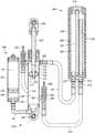
- damping unit 100also includes a second bypass path 256 operable in a rebound stroke of the piston 105 .
- the second bypasscould operate in the compression stroke, the rebound stroke, or both the compression and rebound strokes, depending on the configuration of the check valve 180 or omission thereof.
- the second bypass path 256comprises a cooling assembly 200 that comprises a cylinder body 202 , a lower seal 212 and an upper seal 214 connected by a connecting rod 206 .
- the lower seal 212may be threaded onto the connecting rod 206 and slid into the lower end of the cylinder body 202 .
- the upper seal 214may then be threaded onto the upper end of the connecting rod 206 to form a fluid reservoir 208 inside the cylinder body 202 .
- the lower seal 212includes a fluid inlet port 215 and a fluid outlet port 216 allowing damping fluid to pass from the rebound portion 103 of the cylinder 102 , through the cylinder body 202 of the cooling assembly 200 , and back to the compression portion 104 of the cylinder 102 .
- the lower seal 212 and upper seal 214may form a fluid-tight seal against the inner surface of the cylinder body 202 using one or more sealing elements such as a rubber O-ring.
- a plurality of radial cooling fins 204may be formed on the outer surface of the cylinder body 202 , which increases the external surface area of the cylinder body 202 , thereby increasing the heat transfer effectiveness of the cooling assembly 200 .
- the cooling fins 204may be made from a material having good thermal conductivity such as, for example, aluminum or copper, or alloys thereof.
- the cylinder body 202is made from a material having good impact resistance, strength, and fatigue life such as aluminum or aluminum alloys.
- the cylinder 202 and cooling fins 204may be constructed from a single piece of material or may be an assembly of multiple parts constructed from separate pieces and/or types of materials having the same or suitable desired properties such as thermal conductivity, strength, and toughness.
- the fluid inlet port 215is fluidly coupled with the rebound portion 103 of the cylinder 102 through a cooling entry aperture 260 in cylinder 102 .
- the fluid outlet port 216is fluidly coupled with the compression portion 104 of the cylinder 102 through a cooling exit aperture 265 in cylinder 102 .
- the cooling entry aperture 260 and the cooling exit aperture 265may be positioned axially near the top and bottom of cylinder 102 , respectively.
- the cooling assembly 200may be connected to the cylinder 102 via flexible hydraulic hoses 221 , 222 and hydraulic fittings.
- the cooling assembly 200may be connected to the cylinder 102 via hydraulic tubes made of rigid material such as stainless steel or aluminum.
- cooling assembly 200may be located remotely from the damping unit 100 , such as near a fan by an air intake for a vehicle.
- a needle-type throttle and check valve 280(hereinafter “check valve 280 ” or “throttle/check valve 280 ”, used interchangeably herein), allowing metered flow in one direction and checking flow in the opposite direction, is located proximate to cooling exit aperture 265 .
- the check valve 280is similar to check valve 180 in the bypass assembly 150 and sets flow resistance through the cooling assembly 200 during the rebound stroke and restricts fluid from entering the cooling assembly 200 during the compression stroke of the piston 105 .
- the check valve 280is spring loaded and biased closed. The initial compression force of the biasing spring 282 is adjusted via valve adjuster 283 thereby allowing a user to preset the needle valve opening pressure and hence the rebound damping fluid flow rate through the cooling assembly 200 . The biasing force of the needle valve spring 282 is overcome by fluid pressure in the hydraulic hose 222 causing the check valve 280 to open during a rebound stroke.
- the cooling assembly 200includes a fluid (e.g. hydraulic or pneumatic) fitting disposed at an end of the check valve 280 , as shown in FIGS. 4-6 .
- the fluid fittingis intended to carry a control signal in the form of fluid pressure to the valve adjuster 283 in order to adjust the needle valve opening pressure of the check valve 280 .
- the check valve 280may be adjusted by remote control from a simple operator-actuated switch located in the passenger compartment of the vehicle.
- the check valve 280may be controlled automatically by an electronic control module or a thermostat configured to monitor the temperature of the damping fluid and decrease the needle valve opening pressure via valve adjuster 283 when the temperature is above a threshold temperature to increase fluid flow through the cooling assembly 200 or increase the needle valve opening pressure via valve adjuster 283 when the temperature is below a threshold temperature to decrease fluid flow through the cooling assembly 200 .
- Operation of the check valve 280may be generally as described in relation to check valve 180 .
- the fluid outlet port 216is fluidly coupled to the fluid reservoir 208 formed in the cylinder body 202 by a tube 220 that forces fluid that flows through the fluid outlet port 216 to be drawn from the far end of the cylinder body 202 , opposite the end of the cylinder body 202 that includes both the fluid inlet port 215 and the fluid outlet port 216 .
- a tube 220that forces fluid that flows through the fluid outlet port 216 to be drawn from the far end of the cylinder body 202 , opposite the end of the cylinder body 202 that includes both the fluid inlet port 215 and the fluid outlet port 216 .
- damping unit 100may be compressed, where piston 105 is forced towards the lower end of the cylinder body 102 .
- the fluid pressure in the compression portion 104 of the cylinder body 102increases as piston 105 moves into the cylinder body 102 . Consequently, fluid is forced through the flow path 110 and past shims 116 into the rebound portion 103 of the cylinder body 102 . If the fluid pressure in the compression portion 104 of the cylinder body 102 is larger than the needle valve opening pressure of check valve 180 , then fluid may also flow into the rebound portion 103 of the cylinder body 102 via the bypass assembly 150 .
- check valve 280prevents fluid from flowing from the compression portion 104 of the cylinder body 102 through the cooling exit aperture 265 and into the cooling assembly 200 .
- the fluid pressure in the rebound portion 103 of the cylinder body 102increases as piston 105 moves up through the cylinder body 102 . Fluid is forced through flow path 112 and shims 115 into the compression portion 104 of the cylinder body 102 . If the fluid pressure in the rebound portion 103 of the cylinder body 102 is larger than the needle valve opening pressure of check valve 280 , then fluid may also flow from the rebound portion 103 of the cylinder body 102 into the cooling assembly 200 via hydraulic hose 221 and into the compression portion 104 of the cylinder body 102 via the hydraulic hose 222 . As the fluid passes through cylinder body 202 of the cooling assembly 200 , heat from the fluid is transferred to the air surrounding the cooling assembly 200 .
- the damper unit 100includes only one bypass circuit comprising a cooler assembly 200 as described herein, where the bypass circuit includes no check valve, and where the piston 105 further omits fluid paths 110 , 112 therein such that all damping fluid is forced to flow through the cooler assembly 200 during both the compression stroke and the rebound stroke.
- the check valves 180 and 280may not be included.
- the size of entry apertures 160 , 260 and exit apertures 165 , 265may be designed to restrict the amount of fluid flow through the bypass assembly 150 or the cooling assembly 200 .
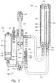
- FIG. 2is a sectional side elevation view of a suspension damping unit 100 that implements an integrated reserve fluid reservoir 300 , according to another example embodiment.
- the reserve fluid reservoir 300stores damping fluid in a reservoir portion 128 of a reservoir cylinder 125 that is in fluid communication with the compression portion 104 of the cylinder 102 .
- the reservoir 300receives and supplies reserve damping fluid as rod 107 moves in and out of the cylinder 102 , accounting for the small change in volume of the damping fluid caused by the intrusion of the rod 107 into the rebound portion 103 of the cylinder 102 .
- the reservoir 300includes a floating piston 130 moveably mounted within the cylinder 125 , with a volume of gas 55 on a backside (“blind end”) of the floating piston 130 , the gas being compressible as the reservoir portion 128 of the cylinder 125 fills with fluid due to movement of the rod 107 .
- a floating piston 130moveably mounted within the cylinder 125
- the reservoir portion 128 of the reservoir cylinder 125is fluidly coupled to the compression portion 104 of the cylinder 102 via a tube 50 connected to a fluid port near the lower end of cylinder 102 .
- an exterior surface of the reservoir 300may include cooling fins as described herein generally in relation to the cooling bypass circuit.
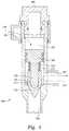
- FIG. 3is a sectional side elevation view of a suspension damping unit 400 , according to yet another example embodiment.
- damping unit 400is a position-sensitive shock absorber including a cylinder 404 having an interior 406 , first and second ends 408 , 410 and defining an axis 412 .
- a floating piston 414divides interior 406 into a damping fluid chamber 416 and a gas chamber 418 .
- Gas chamber 418can be pressurized through a pressurization port 420 .
- Gas chamber 418 and floating piston 414accommodate the volume of oil or other damping fluid within chamber 416 displaced by the movement of shaft 419 into the damping fluid chamber 416 .
- a vented piston 422is movably mounted within the cylinder 404 for moving between the first and second ends 408 , 410 of the cylinder 404 .
- a number of axially separated bypass openings 424 , 426 , 428 , 430 , 432are formed through the cylinder 404 .
- a bypass cylinder 436surrounds cylinder 404 and defines a cylindrical bypass channel 438 .
- Bypass openings 424 , 426 and 432are always open and fluidly couple the damping fluid chamber 416 and the bypass channel 438 to permit some damping fluid to bypass the vented damping piston 422 when the piston is positioned between these bypass openings thus reducing the damping during this portion of the stroke.
- bypass openings 428 , 430are covered by expandable bands 440 , 442 positioned within annular grooves formed in the outer surface of cylinder 404 .
- Bands 440 , 442act as check valve elements that permit fluid flow from the damping fluid chamber 416 to the annular bypass channel 438 but restrict, and typically prevent, fluid flow in the opposite direction.
- the shock absorberwill exhibit different damping characteristics along the same segment of the stroke depending upon whether the stroke is the compression stroke or the rebound stroke.
- cooling fins 450are formed on an outer surface of the bypass cylinder 436 .
- the cooling fins 450may be made from a material exhibiting good thermal conductivity such as copper or aluminum, as well as alloys thereof. Damping fluid passing through the bypass channel 438 is cooled as heat from the damping fluid is transferred to air flowing over the cooling fins 450 of the bypass cylinder 436 . The cooler damping fluid is then circulated back into the damping fluid chamber 416 through bypass openings 424 , 426 , and 432 .
- FIGS. 4, 5, and 6are enlarged views showing a remotely operable needle valve 500 in various positions, according to some example embodiments.
- valve 500may be used in place of check valve 180 or check valve 280 to provide a remote-operation capability to the bypass channels of damping unit 100 .
- the valve 500is in a damping-open position (fluid path shown by arrow 501 ) permitting the bypass channel to operate and let fluid flow through the bypass channel.
- the valve 500includes a valve body 504 housing a movable piston 505 which is sealed within the body. Three fluid communication points are provided in the body including an inlet 502 and outlet 503 for fluid passing through the valve 500 as well as an inlet 525 for control fluid as will be described herein.
- a shaft 510Extending from a first end of the piston 505 is a shaft 510 having a cone-shaped member 512 (other shapes such as spherical or flat, with corresponding seats, will also work suitably well) disposed on an end thereof.
- the cone-shaped member 512is telescopically mounted relative to, and movable on, the shaft 510 and is biased in an extended position ( FIG. 5 ) due to a spring 515 coaxially mounted on the shaft 510 between the member 512 and the piston 505 . Due to the spring biasing, the cone-shaped member 512 normally seats itself against a seat 517 formed in an interior of the body 504 .
- valve 500e.g. member 512
- the characteristics of the spring 515are typically chosen to permit the valve 500 (e.g. member 512 ) to open at a predetermined bypass pressure, with a predetermined amount of control pressure applied to inlet 525 .
- higher control pressure at inlet 525will result in higher bypass pressure required to open the valve 500 which decreases fluid flow through the bypass channel.
- the valve 500is open in both directions when the valve piston 505 is “topped out” against valve body 504 .
- valve piston 505when the valve piston 505 is abutted or “topped out” against valve body 504 the spring 515 and relative dimensions of the valve 500 still allow for the cone member to engage the valve seat thereby closing the valve.
- backflow through the bypass channelis always substantially closed and cracking pressure from fluid flow through the bypass channel is determined by the pre-compression in the spring 515 .
- additional fluid pressuremay be added to the inlet through port 525 to increase the cracking pressure of valve 500 and thereby decrease fluid flow through the bypass channel over that value provided when the spring 515 is “topped out.”
- some or all of the bypass channels (or channel) on a given suspension unitmay be configured to allow or restrict both compression damping and rebound damping bypass.
- FIG. 5shows the valve 500 in a closed position (which it assumes during a rebound stroke of the damper).
- the cone shaped member 512is seated against seat 517 due to the force of the spring 515 and absent an opposite force from fluid entering the valve along the bypass channel.
- a gap 520is formed between the end of the shaft 510 and an interior of member 512 .
- a vent 521is provided to relieve any pressure formed in the gap.
- Inlet 525is formed in the valve body 504 for operation of the valve.
- inlet 525may be pressurized to shift the valve 500 to a third or “locked-out” position.
- the valve 500is shown in the locked-out position, thereby preventing fluid flow through the bypass channel in either direction, regardless of whether the damping unit 100 is in a compression stroke or a rebound stroke.
- the control inlet 525provides a fluid path 530 to a piston surface 527 formed on an end of the piston 505 , opposite the cone-shaped member 512 . Specifically, activating pressure is introduced via inlet 525 to move the piston 505 and with it, member 512 toward seat 517 .
- Sufficient activating pressurefully compresses the spring 515 (substantial stack out) and/or closes the gap 520 thereby closing the cone 512 against the seat 517 , sealing the bypass channel to both compression flow in one direction and rebound flow in the other direction.
- the valve 500can be shifted to the third, locked-out position from either the first, open position or the second, closed position. Note that, when in the “locked out” position, the valve 500 as shown will open to fluid flow through the bypass channel when the fluid flow pressure acting over the surface area of the seated valve cone 512 exceeds the inlet 525 pressure acting over the surface area of the piston 505 .
- Such inlet 525 pressuremay be selected to correspond to a desired overpressure relief value or “blow off” value, thereby allowing fluid to flow through the bypass channel under “extreme” conditions even when the bypass is “locked out”.
- the valve 500is intended to be shifted to the locked-out position with control fluid acting upon piston 505 .
- the activating pressure via inlet 525is adjusted so that the valve 500 is closed to fluid flowing through the bypass channel in one direction (e.g., opposite bypass paths 156 , 256 ) but with the spring 515 not fully compressed or stacked out. In such a position, a high enough fluid force (e.g. fluid pressure in the bypass channel) will still open the valve 500 and allow fluid to pass through the valve 500 .
- the activating pressurecontrolled remotely, may be adjusted between levels where the lock-out is not energized and levels where the lock-out is fully energized. The activating pressure may also be adjusted at intermediate levels to create more or less fluid flow through the bypass channel.
- the activating pressuremay be created by hydraulic or pneumatic input or any other suitable pressure source.
- valve 500is moved to a locked-out position and the bypass feature (i.e., compression bypass or cooling bypass) of the damping unit 100 is disabled by remote control from a simple operator-actuated switch located in the passenger compartment of the vehicle.
- fluid pressure for controlling (e.g. locking-out) the valve 500is provided by the vehicle's on-board source of pressurized hydraulic fluid created by, for example, the vehicle power steering system.
- pneumatic pressureis used to control (e.g. close) the valve 500 where the pneumatic pressure is generated by an on-board compressor and accumulator system and conducted to the valve 500 via a fluid conduit.
- a linear electric motore.g.
- solenoidor other suitable electric actuator, is used, in lieu of the aforementioned inlet 525 pressure, to move the “piston” axially within valve body.
- a shaft of the electric actuator(not shown) may be fixed to the piston such that axial movement of the shaft causes axial movement of the piston which in turn causes movement of the cone 512 (and compression of the spring as appropriate).
- the electric actuatoris configured to “push” the piston towards a closed position and to “pull” the piston away from the closed position depending on the direction of the current switched through the actuator.
- FIG. 7is a schematic diagram illustrating a sample circuit 600 used to provide remote control of a bypass valve 500 using a vehicle's power steering fluid (although any suitable fluid pressure source may be substituted for reservoir 610 as could an electrical current source in the case of an electrically actuated valve), according to one example embodiment.
- a fluid pathway 605 having a control-operated valve 602 thereinruns from a fluid (or current) reservoir 610 that is kept pressurized by, in one embodiment, a power steering pump (not shown) to a check valve 500 that is operable, for example, by a user selectable dash board control 615 .
- the valve 502permits fluid to travel to the inlet 525 of the check valve 500 , thereby allowing a user or electronic controller to adjust the needle valve opening pressure of the valve 500 .
- the control 615is a three position switch that allows a user to remotely set the needle valve opening pressure of the valve 500 by increasing or decreasing the pressure of fluid in pathway 605 .
- the control 615is a rheostat that allows a user to set the pressure of fluid in pathway 605 via a linearly actuated pressure regulator 602 based on the position of the rheostat. While FIG.
- valve 502could be plumbed to simultaneously provide a signal to two or more check valves 500 operable with two or more vehicle damping units and/or with a single damping unit having multiple valves 500 . Additional switches could permit individual operation of separate damper check valves 500 , whether on separate dampers or on the same damper, depending upon an operator's needs.
- FIG. 7uses fluid power for operating the valve 500 , a variety of means are available for remotely controlling a valve. For instance, a source of electrical power from a 12 volt battery could be used to operate a solenoid member.
- the signalcan be either via a physical conductor or an RF signal (or other wireless such as Bluetooth, WiFi, ANT) from a transmitter operated by the controller 615 to a receiver operable on the valve 500 .
- bypass assembly 150 and cooling assembly 200 check valvescan be used in a variety of ways with many different driving and road variables.
- the bypass assembly 150is controlled based upon vehicle speed in conjunction with the angular location of the vehicle's steering wheel. In this manner, by sensing the steering wheel turn severity (angle of rotation), additional damping can be applied to one damper or one set of dampers on one side of the vehicle (suitable for example to mitigate cornering roll) in the event of a sharp turn at a relatively high speed.
- a transducersuch as an accelerometer measures other aspects of the vehicle's suspension system, like axle force and/or moments applied to various parts of the vehicle, like steering tie rods, and directs change to the bypass valve 180 positioning in response thereto.
- the bypass valve 180can be controlled at least in part by a pressure transducer measuring pressure in a vehicle tire and adding damping characteristics to some or all of the wheels in the event of, for example, an increased or decreased pressure reading.
- the damper bypass assembly 150 or bypass channelsare controlled in response to braking pressure (as measured for example by a brake pedal sensor or brake fluid pressure sensor or accelerometer).
- a parametermight include a gyroscopic mechanism that monitors vehicle trajectory and identifies a “spin-out” or other loss of control condition and adds/reduces damping to some or all of the vehicle's dampers in the event of a loss of control to help the operator of the vehicle to regain control.
- the fluid flow rate through the cooling assembly 200can be controlled, at least in part, based on the temperature of the damping fluid.
- FIG. 8illustrates, for example, a system including four variables: rod speed, rod position, vehicle speed, and fluid temperature, according to one example embodiment. Any or all of the variables shown may be considered by processor 702 in controlling the valve 500 . Any other suitable vehicle operation variable may be used in addition to or in lieu of the variables 705 , 710 , 715 , and 720 such as for example piston rod compression strain, eyelet strain, vehicle mounted accelerometer data or any other suitable vehicle or component performance data.
- a suitable proximity sensor or linear coil transducer or other electro-magnetic transduceris incorporated in the damping cylinder 102 to provide a sensor to monitor the position and/or speed of the piston 105 (and suitable magnetic tag) with respect to the cylinder 102 .
- the magnetic transducerincludes a waveguide and a magnet, such as a doughnut (toroidal) magnet that is joined to the cylinder and oriented such that the magnetic field generated by the magnet passes through the piston rod and the waveguide.
- Electric pulsesare applied to the waveguide from a pulse generator that provides a stream of electric pulses, each of which is also provided to a signal processing circuit for timing purposes.
- a pulse generatorthat provides a stream of electric pulses, each of which is also provided to a signal processing circuit for timing purposes.
- a magnetic fieldis formed surrounding the waveguide. Interaction of this field with the magnetic field from the magnet causes a torsional strain wave pulse to be launched in the waveguide in both directions away from the magnet.
- a coil assembly and sensing tapeis joined to the waveguide.
- the strain wavecauses a dynamic effect in the permeability of the sensing tape which is biased with a permanent magnetic field by the magnet.
- the dynamic effect in the magnetic field of the coil assembly due to the strain wave pulseresults in an output signal from the coil assembly that is provided to the signal processing circuit along signal lines.
- the signal processing circuitcan calculate a distance of the magnet from the coil assembly or the relative velocity between the waveguide and the magnet.
- the signal processing circuitprovides an output signal, either digital or analog, proportional to the calculated distance and/or velocity.
- a separate wheel speed transducer for sensing the rotational speed of a wheel about an axleincludes housing fixed to the axle and containing therein, for example, two permanent magnets.
- the magnetsare arranged such that an elongated pole piece commonly abuts first surfaces of each of the magnets, such surfaces being of like polarity.
- Two inductive coils having flux-conductive cores axially passing therethroughabut each of the magnets on second surfaces thereof, the second surfaces of the magnets again being of like polarity with respect to each other and of opposite polarity with respect to the first surfaces.
- Wheel speed transducersare described in U.S. Pat. No. 3,986,118, which is incorporated by reference herein in its entirety.
- a logic unit 702 with user-definable settingsreceives inputs from the rod speed 710 and location 705 transducers as well as the wheel speed transducer 715 .
- the logic unitis user-programmable and depending on the needs of the operator, the unit records the variables and then if certain criteria are met, the logic circuit sends its own signal to the bypass assembly 150 to either close or open (or optionally throttle) the check valve 180 . Thereafter, the condition of the bypass valve 180 is relayed back to the logic unit 702 .
- the logic unit 702 with user-definable settingsreceives inputs from the temperature sensor 720 , and adjusts the control signal to the cooling assembly 200 to either close or open (or optionally throttle) the check valve 280 . Thereafter, the condition of the check valve 280 is relayed back to the logic unit 702 .
- the logic shown in FIG. 8assumes a single damper but the logic circuit is usable with any number of dampers or groups of dampers. For instance, the dampers on one side of the vehicle can be acted upon while the vehicles other dampers remain unaffected.
Landscapes
- Engineering & Computer Science (AREA)
- General Engineering & Computer Science (AREA)
- Mechanical Engineering (AREA)
- Physics & Mathematics (AREA)
- Electromagnetism (AREA)
- Fluid-Damping Devices (AREA)
- Vehicle Body Suspensions (AREA)
Abstract
Description
Claims (29)
Priority Applications (2)
| Application Number | Priority Date | Filing Date | Title |
|---|---|---|---|
| US15/873,796US10718397B2 (en) | 2011-03-03 | 2018-01-17 | Cooler for a suspension damper |
| US16/932,501US12110944B2 (en) | 2011-03-03 | 2020-07-17 | Cooler for a suspension damper |
Applications Claiming Priority (5)
| Application Number | Priority Date | Filing Date | Title |
|---|---|---|---|
| US201161449045P | 2011-03-03 | 2011-03-03 | |
| US13/411,086US8763770B2 (en) | 2011-03-03 | 2012-03-02 | Cooler for a suspension damper |
| US14/293,805US9416841B2 (en) | 2010-01-07 | 2014-06-02 | Cooler for a suspension damper |
| US15/234,914US10975929B2 (en) | 2011-03-03 | 2016-08-11 | Cooler for a suspension damper |
| US15/873,796US10718397B2 (en) | 2011-03-03 | 2018-01-17 | Cooler for a suspension damper |
Related Parent Applications (1)
| Application Number | Title | Priority Date | Filing Date |
|---|---|---|---|
| US15/234,914ContinuationUS10975929B2 (en) | 2011-03-03 | 2016-08-11 | Cooler for a suspension damper |
Related Child Applications (1)
| Application Number | Title | Priority Date | Filing Date |
|---|---|---|---|
| US16/932,501ContinuationUS12110944B2 (en) | 2011-03-03 | 2020-07-17 | Cooler for a suspension damper |
Publications (2)
| Publication Number | Publication Date |
|---|---|
| US20180142755A1 US20180142755A1 (en) | 2018-05-24 |
| US10718397B2true US10718397B2 (en) | 2020-07-21 |
Family
ID=45811323
Family Applications (5)
| Application Number | Title | Priority Date | Filing Date |
|---|---|---|---|
| US13/411,086Active2032-06-25US8763770B2 (en) | 2010-01-07 | 2012-03-02 | Cooler for a suspension damper |
| US14/293,805ActiveUS9416841B2 (en) | 2010-01-07 | 2014-06-02 | Cooler for a suspension damper |
| US15/234,914ActiveUS10975929B2 (en) | 2011-03-03 | 2016-08-11 | Cooler for a suspension damper |
| US15/873,796ActiveUS10718397B2 (en) | 2011-03-03 | 2018-01-17 | Cooler for a suspension damper |
| US16/932,501ActiveUS12110944B2 (en) | 2011-03-03 | 2020-07-17 | Cooler for a suspension damper |
Family Applications Before (3)
| Application Number | Title | Priority Date | Filing Date |
|---|---|---|---|
| US13/411,086Active2032-06-25US8763770B2 (en) | 2010-01-07 | 2012-03-02 | Cooler for a suspension damper |
| US14/293,805ActiveUS9416841B2 (en) | 2010-01-07 | 2014-06-02 | Cooler for a suspension damper |
| US15/234,914ActiveUS10975929B2 (en) | 2011-03-03 | 2016-08-11 | Cooler for a suspension damper |
Family Applications After (1)
| Application Number | Title | Priority Date | Filing Date |
|---|---|---|---|
| US16/932,501ActiveUS12110944B2 (en) | 2011-03-03 | 2020-07-17 | Cooler for a suspension damper |
Country Status (2)
| Country | Link |
|---|---|
| US (5) | US8763770B2 (en) |
| EP (1) | EP2495472B1 (en) |
Cited By (24)
| Publication number | Priority date | Publication date | Assignee | Title |
|---|---|---|---|---|
| US10807433B2 (en) | 2009-01-07 | 2020-10-20 | Fox Factory, Inc. | Method and apparatus for an adjustable damper |
| US10821795B2 (en) | 2009-01-07 | 2020-11-03 | Fox Factory, Inc. | Method and apparatus for an adjustable damper |
| US10859133B2 (en) | 2012-05-10 | 2020-12-08 | Fox Factory, Inc. | Method and apparatus for an adjustable damper |
| US11162555B2 (en) | 2008-08-25 | 2021-11-02 | Fox Factory, Inc. | Methods and apparatus for suspension lock out and signal generation |
| US11168758B2 (en) | 2009-01-07 | 2021-11-09 | Fox Factory, Inc. | Method and apparatus for an adjustable damper |
| US11279198B2 (en) | 2009-10-13 | 2022-03-22 | Fox Factory, Inc. | Methods and apparatus for controlling a fluid damper |
| US11279199B2 (en) | 2012-01-25 | 2022-03-22 | Fox Factory, Inc. | Suspension damper with by-pass valves |
| US11299233B2 (en) | 2009-01-07 | 2022-04-12 | Fox Factory, Inc. | Method and apparatus for an adjustable damper |
| US11306798B2 (en) | 2008-05-09 | 2022-04-19 | Fox Factory, Inc. | Position sensitive suspension damping with an active valve |
| US11408482B2 (en) | 2009-01-07 | 2022-08-09 | Fox Factory, Inc. | Bypass for a suspension damper |
| US11472252B2 (en) | 2016-04-08 | 2022-10-18 | Fox Factory, Inc. | Electronic compression and rebound control |
| US11499601B2 (en)* | 2009-01-07 | 2022-11-15 | Fox Factory, Inc. | Remotely operated bypass for a suspension damper |
| US11505024B2 (en) | 2019-10-08 | 2022-11-22 | Off-Road Research LLC | Electronically controlled external damper reservoir |
| US11519477B2 (en) | 2009-01-07 | 2022-12-06 | Fox Factory, Inc. | Compression isolator for a suspension damper |
| US11549565B2 (en) | 2009-01-07 | 2023-01-10 | Fox Factory, Inc. | Method and apparatus for an adjustable damper |
| US11619278B2 (en) | 2009-03-19 | 2023-04-04 | Fox Factory, Inc. | Methods and apparatus for suspension adjustment |
| US11708878B2 (en) | 2010-01-20 | 2023-07-25 | Fox Factory, Inc. | Remotely operated bypass for a suspension damper |
| US11859690B2 (en) | 2009-10-13 | 2024-01-02 | Fox Factory, Inc. | Suspension system |
| US11897571B2 (en) | 2008-11-25 | 2024-02-13 | Fox Factory, Inc. | Seat post |
| US11946526B2 (en) | 2020-11-26 | 2024-04-02 | Bombardier Recreational Products Inc. | Shock absorber for a vehicle |
| US11958328B2 (en) | 2011-09-12 | 2024-04-16 | Fox Factory, Inc. | Methods and apparatus for suspension set up |
| US12103344B2 (en) | 2021-08-06 | 2024-10-01 | AllTech Motorsports Inc. | Control coil over internal bypass damper for automotive suspensions |
| US12103349B2 (en) | 2009-03-19 | 2024-10-01 | Fox Factory, Inc. | Methods and apparatus for selective spring pre-load adjustment |
| US12122205B2 (en) | 2009-01-07 | 2024-10-22 | Fox Factory, Inc. | Active valve for an internal bypass |
Families Citing this family (42)
| Publication number | Priority date | Publication date | Assignee | Title |
|---|---|---|---|---|
| US20120305350A1 (en) | 2011-05-31 | 2012-12-06 | Ericksen Everet O | Methods and apparatus for position sensitive suspension damping |
| US9033122B2 (en) | 2009-01-07 | 2015-05-19 | Fox Factory, Inc. | Method and apparatus for an adjustable damper |
| US8857580B2 (en) | 2009-01-07 | 2014-10-14 | Fox Factory, Inc. | Remotely operated bypass for a suspension damper |
| EP3666347B1 (en) | 2008-11-25 | 2021-10-20 | Fox Factory, Inc. | Computer usable storage medium for virtual competition |
| US9556925B2 (en)* | 2009-01-07 | 2017-01-31 | Fox Factory, Inc. | Suspension damper with by-pass valves |
| US8936139B2 (en) | 2009-03-19 | 2015-01-20 | Fox Factory, Inc. | Methods and apparatus for suspension adjustment |
| US9162573B2 (en) | 2010-06-03 | 2015-10-20 | Polaris Industries Inc. | Electronic throttle control |
| EP2402239B1 (en) | 2010-07-02 | 2020-09-02 | Fox Factory, Inc. | Adjustable seat post |
| EP2495472B1 (en) | 2011-03-03 | 2024-05-01 | Fox Factory, Inc. | Cooler for a suspension damper |
| US8910757B2 (en)* | 2012-07-25 | 2014-12-16 | Yuan-Hung WEN | Heat-dissipating device for hydraulic brake system |
| EP2917054B1 (en)* | 2012-11-07 | 2018-09-05 | Polaris Industries Inc. | Vehicle having suspension with continuous damping control |
| US9205717B2 (en) | 2012-11-07 | 2015-12-08 | Polaris Industries Inc. | Vehicle having suspension with continuous damping control |
| CN103851247A (en)* | 2012-11-29 | 2014-06-11 | 费希尔控制国际公司 | Wireless position transducer for a valve |
| US9428224B2 (en)* | 2013-06-28 | 2016-08-30 | GM Global Technology Operations LLC | Drainable section stabilizer sleeve |
| US10996236B2 (en)* | 2014-07-22 | 2021-05-04 | Fisher Controls International Llc | Control device position feedback with accelerometer |
| US10183539B2 (en)* | 2014-09-17 | 2019-01-22 | Fox Factory, Inc. | Shock absorber |
| CN107406094B (en) | 2014-10-31 | 2020-04-14 | 北极星工业有限公司 | System and method for controlling a vehicle |
| EP3488121B1 (en) | 2016-07-20 | 2022-03-02 | Elka Suspension Inc. | Position-relative damper assist system |
| EP3835615A1 (en)* | 2016-08-25 | 2021-06-16 | Fox Factory, Inc. | Remotely operated bypass for a suspension damper |
| CN110121438B (en) | 2016-11-18 | 2023-01-31 | 北极星工业有限公司 | vehicles with adjustable suspension |
| US20180216692A1 (en)* | 2017-01-30 | 2018-08-02 | Fox Factory, Inc. | Twin tube shock with adjustable pressure regulation |
| US20190154100A1 (en)* | 2017-01-30 | 2019-05-23 | Fox Factory, Inc. | Twin tube shock with adjustable pressure regulation |
| US10406884B2 (en) | 2017-06-09 | 2019-09-10 | Polaris Industries Inc. | Adjustable vehicle suspension system |
| CN108518444B (en)* | 2018-03-22 | 2020-02-28 | 杭州电子科技大学 | Permanent magnet and excitation coil hybrid magnetorheological damper and damping adjustment method |
| CN108730399B (en)* | 2018-06-20 | 2023-04-18 | 安徽工程大学 | Vibration damping system |
| US10987987B2 (en) | 2018-11-21 | 2021-04-27 | Polaris Industries Inc. | Vehicle having adjustable compression and rebound damping |
| DE102019118422B3 (en)* | 2019-07-08 | 2021-01-07 | Otto Bock Healthcare Products Gmbh | Actuator and heat storage for actuator |
| CN111188865B (en)* | 2020-02-17 | 2021-08-20 | 常州机电职业技术学院 | A hydraulic damper with stiffness adjustment device |
| CN111237376B (en)* | 2020-02-20 | 2021-07-27 | 唐山保靓汽车配件有限公司 | Heat dissipation device for shock absorber |
| GB202002732D0 (en)* | 2020-02-26 | 2020-04-08 | Carbon Air Ltd | Gas pressurised shock absorber |
| US11554864B2 (en)* | 2020-03-27 | 2023-01-17 | Textron Innoations Inc. | Techniques for increasing heat dissipation in lead-lag dampers |
| US11279194B2 (en)* | 2020-04-02 | 2022-03-22 | Thyssenkrupp Bilstein Of America Inc. | Damper with reservoir |
| US12397878B2 (en) | 2020-05-20 | 2025-08-26 | Polaris Industries Inc. | Systems and methods of adjustable suspensions for off-road recreational vehicles |
| US11927242B2 (en)* | 2020-06-05 | 2024-03-12 | Fox Factory, Inc. | Electronic external bypass |
| MX2022015902A (en) | 2020-07-17 | 2023-01-24 | Polaris Inc | Adjustable suspensions and vehicle operation for off-road recreational vehicles. |
| US12398776B2 (en)* | 2021-09-10 | 2025-08-26 | Fox Factory, Inc. | Race cooler with integrated base valve |
| DE102021212104A1 (en) | 2021-10-27 | 2023-04-27 | Zf Friedrichshafen Ag | Adjustable vibration damper with a hydraulic end stop |
| CN114877000B (en)* | 2022-04-13 | 2024-05-10 | 山东阿诺达汽车零件制造有限公司 | Shock absorber heat abstractor |
| DE102023115403A1 (en) | 2023-06-13 | 2024-12-19 | Dr. Ing. H.C. F. Porsche Aktiengesellschaft | Hydraulic system of an active chassis of a motor vehicle and motor vehicle |
| CN116877620B (en)* | 2023-08-15 | 2025-09-09 | 中国矿业大学 | Side force resistant bottom limiting and damping-variable self-adaptive cooling system for hydro-pneumatic suspension |
| CN118746040B (en)* | 2024-08-15 | 2025-09-23 | 浙江吉利控股集团有限公司 | Air spring vibration reduction system, vehicle, and air spring vibration reduction system control method |
| CN119196220B (en)* | 2024-11-27 | 2025-02-25 | 江苏鼎吉能源工程技术有限公司 | A magnetorheological damper |
Citations (159)
| Publication number | Priority date | Publication date | Assignee | Title |
|---|---|---|---|---|
| US1492731A (en) | 1922-12-14 | 1924-05-06 | Kerr Benjamin | Shock absorber |
| US1575973A (en) | 1926-03-09 | Shock absorber | ||
| US2018312A (en) | 1930-08-20 | 1935-10-22 | Rollin H Moulton | Shock absorber |
| US2492331A (en) | 1947-03-27 | 1949-12-27 | Spring Russell Mason | Shock absorber valve regulator |
| US2725076A (en) | 1953-07-03 | 1955-11-29 | Crane Co | Guided closure unit for check valves and the like |
| US2838140A (en) | 1955-11-03 | 1958-06-10 | Marlin B Rasmusson | Hydraulic dash-pot controller for an actuator |
| US2897613A (en) | 1956-04-25 | 1959-08-04 | Int Harvester Co | Hydraulic carrying-lock for earth-working scrapers |
| US2941629A (en) | 1954-12-06 | 1960-06-21 | Rohacs Etienne | Valves |
| US2991804A (en) | 1959-05-27 | 1961-07-11 | Gen Motors Corp | Air suspension and control apparatus therefor |
| US3202413A (en) | 1962-04-13 | 1965-08-24 | Hoesch Ag | Fluid-pressure devices for vehicle suspensions or the like |
| US3277985A (en) | 1964-11-06 | 1966-10-11 | Kelsey Hayes Co | Air cooled disk brakes |
| US3286797A (en) | 1964-06-29 | 1966-11-22 | Parker Hannifin Corp | Hydraulic control unit |
| US3420493A (en) | 1965-12-13 | 1969-01-07 | Wilbur P Kraft | Combination metering,check and shut-off valve |
| US3547465A (en) | 1967-10-09 | 1970-12-15 | Hoesch Ag | Hydropneumatic suspension unit for use in vehicles or the like |
| US3556137A (en) | 1969-05-15 | 1971-01-19 | Sloan Valve Co | Control valves |
| US3584331A (en) | 1969-06-13 | 1971-06-15 | Rixson Inc | Hydraulic door checking mechanism |
| US3605960A (en) | 1969-05-27 | 1971-09-20 | Jerome R Singer | Automatically adjustable shock absorbers |
| US3714953A (en) | 1971-10-20 | 1973-02-06 | Nat Water Blast Inc | Pressure relief valve |
| US3750856A (en) | 1971-12-09 | 1973-08-07 | G Kenworthy | Adjustable, pressure compensating shock absorber/buffer |
| US3791408A (en) | 1972-05-31 | 1974-02-12 | Yuken Kogyo Co Ltd | Electromagnetic pressure-telecontrolling valve |
| US3795291A (en) | 1971-09-17 | 1974-03-05 | Yamaha Motor Co Ltd | Hydraulic shock-absorbing device |
| US3986118A (en) | 1975-05-02 | 1976-10-12 | Goodyear Aerospace Corporation | Simplified wheel speed transducer |
| US4022113A (en) | 1975-12-10 | 1977-05-10 | Blatt Leland F | Flow control valve |
| US4061320A (en) | 1976-05-03 | 1977-12-06 | Joe Frank Warner | Two cylinder shock absorber system |
| US4072087A (en) | 1975-09-17 | 1978-02-07 | Caterpillar Tractor Co. | Digital positioner for remote actuation of a control valve |
| US4139186A (en) | 1976-11-26 | 1979-02-13 | Itt Industries, Inc. | Retractable shock absorber |
| US4174098A (en) | 1978-07-03 | 1979-11-13 | Ace Controls, Inc. | Shock absorber and mounting means therefor |
| US4183509A (en) | 1977-03-22 | 1980-01-15 | Honda Giken Kogyo Kabushiki Kaisha | Shock absorber for vehicle use |
| US4206935A (en) | 1977-10-21 | 1980-06-10 | General Motors Corporation | Motor vehicle roll control system |
| JPS5761246U (en) | 1980-09-22 | 1982-04-12 | ||
| US4333668A (en) | 1979-12-17 | 1982-06-08 | The Bendix Corporation | Electronic adaptive ride control system |
| US4334711A (en) | 1980-10-27 | 1982-06-15 | American Standard Inc. | System for automatically delaying application of a snow brake for a railway vehicle |
| US4337850A (en) | 1978-02-06 | 1982-07-06 | Tokico Ltd. | Hydraulic damper |
| JPS58137142U (en) | 1982-03-12 | 1983-09-14 | 株式会社昭和製作所 | Hydraulic shock absorber damping force variable device |
| US4491207A (en) | 1983-07-15 | 1985-01-01 | Lord Corporation | Fluid control means for vehicle suspension system |
| US4502673A (en) | 1982-02-11 | 1985-03-05 | Applied Power Inc. | Integral shock absorber and spring assembly |
| US4548233A (en) | 1983-04-27 | 1985-10-22 | Mannesmann Rexroth Gmbh | Electrically controlled pressure relief valve including a hydraulic bias |
| US4616810A (en)* | 1985-03-28 | 1986-10-14 | Richardson Wayne U | Liquid cooled shock absorber |
| US4620619A (en) | 1982-05-20 | 1986-11-04 | Atsugi Motor Parts Co., Ltd. | Variable-damping-force shock absorber |
| US4660689A (en) | 1985-03-22 | 1987-04-28 | Toyota Jidosha Kabushiki Kaisha | Hydraulic buffer |
| US4743000A (en) | 1985-04-12 | 1988-05-10 | Robert Bosch Gmbh | Method and apparatus for controlling spring stiffness, in particular in vehicles |
| US4750735A (en) | 1986-10-09 | 1988-06-14 | M & R Industries, Inc. | Adjustable hydraulic load-resisting mechanisms for exercise machines |
| DE3709447A1 (en) | 1987-03-23 | 1988-10-13 | Bilstein August Gmbh Co Kg | ADJUSTABLE SHOCK ABSORBER, ESPECIALLY FOR MOTOR VEHICLES |
| US4786034A (en) | 1986-04-02 | 1988-11-22 | Robert Bosch Gmbh | Apparatus for damping courses of movement |
| JPH0193637A (en) | 1987-10-05 | 1989-04-12 | Nhk Spring Co Ltd | Suspension for vehicle |
| JPH01106721A (en) | 1987-10-20 | 1989-04-24 | Tokico Ltd | Shock absorber |
| US4826207A (en) | 1987-01-16 | 1989-05-02 | Honda Giken Kogyo Kabushiki Kaisha | Compound suspension system |
| DE3738048A1 (en) | 1987-11-09 | 1989-05-18 | Rexroth Mannesmann Gmbh | Device for damping the self-movements of the masses of a linear two-mass oscillator |
| US4846317A (en) | 1987-08-25 | 1989-07-11 | Trw Inc. | Strut with controlled variable damping rate |
| US4919166A (en) | 1988-07-05 | 1990-04-24 | Sims Anthony M | Two-way flow valve |
| US4936424A (en) | 1989-05-09 | 1990-06-26 | Costa Vince F | Hydraulic shock absorber with pressure sensitive external valving |
| US4949989A (en) | 1988-04-19 | 1990-08-21 | Atsugi Motor Parts Co., Ltd. | Automotive suspension system with variable suspension characteristics and variable damping force shock absorber therefor |
| DE3924166C1 (en) | 1989-07-21 | 1991-02-28 | Boge Ag, 5208 Eitorf, De | Hydraulic vibration damper with valved piston - has changeover control rod with several surface recesses with different widths |
| US5062660A (en) | 1989-04-28 | 1991-11-05 | Nissan Motor Company, Limited | Pressure medium fluid circuit for active suspension system with variable fluid source discharge rate depending upon magnitude of stroke in relative displacement between vehicular body and suspension member |
| US5087072A (en) | 1989-07-31 | 1992-02-11 | Nissan Motor Company, Limited | Attitude change suppressive control system for active suspension system for automotive vehicle |
| EP0475660A2 (en) | 1990-09-11 | 1992-03-18 | Hyrad Corporation | Quick response adjustable shock absorber & system |
| DE4029090A1 (en) | 1990-09-13 | 1992-03-19 | Hilti Ag | Sound damping pipe-clip insert - has portion on protrusion towards pipe allowing slide movement |
| JPH04203540A (en) | 1990-11-29 | 1992-07-24 | Mazda Motor Corp | Damping force adjusting type hydraulic buffer |
| US5161653A (en) | 1989-04-18 | 1992-11-10 | Hare Sr Nicholas S | Electro-rheological shock absorber |
| US5163742A (en) | 1990-03-08 | 1992-11-17 | Mercedes-Benz Ag | Method of distributing brake pressure to the axles of a motor vehicle with an abs pressure-medium brake |
| US5178242A (en) | 1990-11-19 | 1993-01-12 | Atsugi Unisia Corporation | Hydraulic damper |
| US5203584A (en) | 1990-04-17 | 1993-04-20 | Mazada Motor Corporation | Suspension system for a vehicle |
| US5208749A (en) | 1989-08-11 | 1993-05-04 | Hitachi, Ltd. | Method for controlling active suspension system on the basis of rotational motion model |
| US5207774A (en) | 1991-11-27 | 1993-05-04 | Lord Corporation | Valving for a controllable shock absorber |
| JPH05149364A (en) | 1991-11-30 | 1993-06-15 | Tokico Ltd | Damping force adjustable hydraulic shock absorber |
| US5220983A (en)* | 1990-09-11 | 1993-06-22 | Hyrad Corporation | Shock absorber with heat exchanger and improved cylinder head assembly |
| US5222759A (en) | 1990-02-27 | 1993-06-29 | Robert Bosch Gmbh | Apparatus for active control of body motions in motor vehicles |
| US5230364A (en) | 1991-04-06 | 1993-07-27 | Vickers, Incorporated | Pressure relief valve |
| US5259487A (en) | 1992-07-14 | 1993-11-09 | The Lubrizol Corporation | Adjustable dampers using electrorheological fluids |
| US5277283A (en) | 1988-09-19 | 1994-01-11 | Atsugi Unisia Corporation | Variable damping-characteristics shock absorber with adjustable orifice construction variable of fluid flow restriction depending upon fluid pressure difference |
| US5293971A (en) | 1988-08-02 | 1994-03-15 | Atsugi Unisia Corporation | Shock absorber with damping valve structure having wide range variable damping characteristics |
| US5307907A (en) | 1991-06-11 | 1994-05-03 | Atsugi Unisia Corporation | Hydraulic damper |
| DE4406918A1 (en) | 1993-03-18 | 1994-09-22 | Fichtel & Sachs Ag | Damping valve device |
| US5588510A (en) | 1995-09-25 | 1996-12-31 | Husco International, Inc. | Variable damping force shock absorber |
| US5598337A (en) | 1992-09-30 | 1997-01-28 | Mazda Motor Corporation | Suspension apparatus with driving state feedback for vehicles |
| US5597180A (en) | 1994-08-15 | 1997-01-28 | Ganzel; Blaise J. | Vehicle roll control apparatus |
| US5657840A (en) | 1986-06-05 | 1997-08-19 | Lizell; Magnus B. | Method and apparatus for absorbing mechanical shock |
| US5699885A (en) | 1993-03-18 | 1997-12-23 | Fichtel & Sachs Ag | Vibration damper with adjustable damping force |
| US5810128A (en) | 1995-05-18 | 1998-09-22 | Yamaha Hatsudoki Kabushiki Kaisha | Shock absorber |
| US5813731A (en) | 1996-06-17 | 1998-09-29 | Hhb Limited, L.L.C. | Hydraulic parking brake system for railway vehicles |
| US5884921A (en) | 1996-08-29 | 1999-03-23 | Toyota Jidosha Kabushiki Kaisha | Electric control apparatus for damper device in suspension system of automotive vehicle |
| US5937975A (en) | 1996-06-21 | 1999-08-17 | Fichtel & Sachs Ag | Vibration damper for a motor vehicle and a vibration damper having a damping valve with adjustable damping force for a motor vehicle |
| US5952823A (en) | 1996-03-22 | 1999-09-14 | Mts Systems Corporation | Magnetostrictive linear displacement transducer for a shock absorber |
| US5992450A (en) | 1998-06-30 | 1999-11-30 | Eaton Corporation | Cartridge valve having solenoid bypass and integral relief valve |
| US5996746A (en) | 1997-07-03 | 1999-12-07 | Rockshox, Inc. | Adjustable twin tube shock absorber |
| US6035979A (en) | 1996-06-21 | 2000-03-14 | Fichtel & Sachs Ag | Vibration damper and a vibration damper with a damping valve having an adjustable damping force |
| US6058340A (en) | 1993-12-28 | 2000-05-02 | Tokico Ltd. | Suspension control apparatus |
| DE19849429A1 (en) | 1998-10-27 | 2000-05-11 | Knorr Bremse Systeme | High performance vibration damper |
| US6067490A (en) | 1997-03-18 | 2000-05-23 | Tokico, Ltd. | Suspension control apparatus utilizing a PWM type proportional solenoid valve |
| US6092011A (en) | 1997-04-08 | 2000-07-18 | Unisia Jecs Corporation | Apparatus and method for controlling damping force characteristic of vehicular shock absorber |
| US6142497A (en) | 1997-09-09 | 2000-11-07 | Baldomero; Ricardo R. | Temperature heat sink for damping cartridge |
| US6213263B1 (en) | 1996-07-24 | 2001-04-10 | Donerre Amortisseur | Oil damper system |
| US6217010B1 (en) | 1998-04-07 | 2001-04-17 | Mcneely P. Dennis | Suspension and a dynamic load-compensating fluid spring therefor |
| US6254067B1 (en) | 1999-08-02 | 2001-07-03 | Giant Manufacturing Co., Ltd. | Fluid regulating device for use with a hydraulic cylinder to obtain a variable shock absorbing effect |
| US20010017334A1 (en) | 2000-02-29 | 2001-08-30 | Vincent Alan Henry | Vibration damping apparatus |
| US6293530B1 (en) | 1995-01-10 | 2001-09-25 | Liquidspring Technologies, Inc. | Compressible liquid vibration control system |
| US6296092B1 (en) | 1998-10-28 | 2001-10-02 | Fox Factory, Inc. | Position-sensitive shock absorber |
| US6318525B1 (en) | 1999-05-07 | 2001-11-20 | Marzocchi, S.P.A. | Shock absorber with improved damping |
| US20020008339A1 (en) | 2000-05-22 | 2002-01-24 | Hideaki Ogura | Air spring |
| US6371262B1 (en) | 1999-04-28 | 2002-04-16 | Tokico Ltd. | Damping force control type hydraulic shock absorber |
| US6427812B2 (en) | 1997-07-08 | 2002-08-06 | Active Control Experts, Inc. | Damper and valve |
| US20020121416A1 (en) | 2001-02-19 | 2002-09-05 | Yohei Katayama | Hydraulic cylinder apparatus |
| EP1241087A1 (en) | 2001-03-13 | 2002-09-18 | Shimano Inc. | Bicycle suspension |
| US6474753B1 (en) | 1996-08-21 | 2002-11-05 | Continental Teves Ag & Co., Ohg | Automatically actuated braking system |
| US6592136B2 (en) | 2001-07-02 | 2003-07-15 | Fox Factory, Inc. | Bicycle fork cartridge assembly |
| US20030160369A1 (en) | 2002-01-11 | 2003-08-28 | Laplante John A. | Semi-active shock absorber control system |
| US6619615B1 (en) | 1999-02-06 | 2003-09-16 | Zf Friedrichshafen Ag | Propotional control pressure valve |
| US6648109B2 (en) | 2001-09-13 | 2003-11-18 | Meritor Heavy Vehicle Technology, Llc | Adjustable shock absorber |
| US20040099312A1 (en) | 2002-11-22 | 2004-05-27 | Victor Equipment Company | Gas pressure regulator |
| US20040222056A1 (en) | 2001-08-30 | 2004-11-11 | Fox Robert C. | Inertia valve shock absorber |
| US20050077131A1 (en) | 2003-10-08 | 2005-04-14 | Peter Russell | Shock absorber apparatus |
| US20050098401A1 (en) | 1998-11-11 | 2005-05-12 | Hamilton James M. | Enhanced computer optimized adaptive suspension system and method |
| US20050110229A1 (en) | 2003-10-16 | 2005-05-26 | Ryoji Kimura | Vehicle height adjusting apparatus |
| US6966412B2 (en) | 2003-02-24 | 2005-11-22 | Arctic Cat Inc. | Position-sensitive shock absorber |
| US6978871B2 (en) | 2003-09-17 | 2005-12-27 | Tenneco Automotive Operating Company Inc. | Adjustable damper with control valve, mounted in an external collar |
| US6991076B2 (en) | 1999-04-06 | 2006-01-31 | Specialized Bicycle Components, Inc. | Bicycle damping enhancement system |
| WO2006010207A1 (en) | 2004-07-29 | 2006-02-02 | Graeme Kershaw Robertson | Cooling of vehicle suspension systems |
| US20060065496A1 (en) | 2001-08-30 | 2006-03-30 | Fox Factory, Inc. | Inertia valve shock absorber |
| US20060081431A1 (en) | 2004-10-14 | 2006-04-20 | Tenneco Automotive Operating Company, Inc. | Amplitude controlled orifice valving |
| US20060113834A1 (en) | 2004-11-30 | 2006-06-01 | Nobumichi Hanawa | Damping valve and shock absorber using same |
| US20060124414A1 (en) | 2004-12-09 | 2006-06-15 | Nobumichi Hanawa | Front fork |
| US20060237272A1 (en) | 2004-06-04 | 2006-10-26 | Tan-Cheng Huang | Shock absorber |
| US20060289258A1 (en) | 2003-07-08 | 2006-12-28 | Fox Robert C | Damper with pressure-sensitive compression damping |
| US20070008096A1 (en) | 2005-05-14 | 2007-01-11 | Tracy Randy L | Reversibly mountable acceleration/de-acceleration warning light |
| US20070039790A1 (en) | 2005-08-22 | 2007-02-22 | Technology Investments Limited | Vehicle suspension spring system |
| US20070051573A1 (en) | 2004-11-08 | 2007-03-08 | Norgaard Bret M | Fluid flow regulation of a vehicle shock absorber/damper |
| US7234680B2 (en) | 2001-05-31 | 2007-06-26 | Wendell Hull | Combination valve and regulator with vented seat for use with pressurized gas cylinders, particularly oxygen cylinders |
| US7299112B2 (en) | 2004-11-03 | 2007-11-20 | Activeshock, Inc. | Electrically controlled pressure relief valve and system and method for controlling same |
| JP2007302211A (en) | 2006-05-15 | 2007-11-22 | Toyota Motor Corp | Suspension system |
| US20080006494A1 (en) | 2004-02-10 | 2008-01-10 | Bart Vandewal | Electronically controlled frequency dependent damping |
| US7325660B2 (en) | 2004-11-08 | 2008-02-05 | Thyssenkrupp Bilstein Of America, Inc. | Fluid flow regulation of a vehicle shock absorber/damper |
| WO2008018848A2 (en) | 2006-08-08 | 2008-02-14 | Yerkovych, Valentyn Antonovych | Self-levelling shock absorber with one-direction fluid flow and externally controlled strength |
| US20080059025A1 (en) | 2006-08-29 | 2008-03-06 | Honda Motor Co., Ltd. | Vehicle state estimation system |
| US20090001684A1 (en) | 2007-06-29 | 2009-01-01 | Specialized Bicycle Components, Inc. | Bicycle suspension assembly |
| US20090020382A1 (en) | 2007-07-19 | 2009-01-22 | Van Weelden Curtis L | Piston With An Integral Electrically Operated Adjustment Valve For A Hydraulic Vibration Damper |
| US20090277736A1 (en) | 2008-05-09 | 2009-11-12 | Specialized Bicycle Components, Inc. | Bicycle damper |
| US20090302558A1 (en) | 2008-06-06 | 2009-12-10 | Shimano Inc. | Bicycle suspension system |
| US20090314592A1 (en) | 2006-03-20 | 2009-12-24 | Ohlins Racing Ab | Damper device and manufacture of such a damper device |
| US20100010709A1 (en) | 2008-01-24 | 2010-01-14 | Cannondale Bicycle Corporation | Bicycle distributed computing arrangement and method of operation |
| US20100059964A1 (en) | 2008-09-05 | 2010-03-11 | Sram Corporation | Bicycle Suspension System |
| US20100170760A1 (en) | 2009-01-07 | 2010-07-08 | John Marking | Remotely Operated Bypass for a Suspension Damper |
| US20110174582A1 (en) | 2010-01-20 | 2011-07-21 | Wootten Dennis K | Methods and apparatus for variable damping adjuster |
| US20110214956A1 (en) | 2009-01-07 | 2011-09-08 | John Marking | Remotely operated bypass for a suspension damper |
| US20110284333A1 (en) | 2010-05-20 | 2011-11-24 | Suspa Gmbh | Damper |
| US20110315494A1 (en) | 2009-01-07 | 2011-12-29 | John Marking | Bypass for a suspension damper |
| US20120018264A1 (en) | 2010-07-21 | 2012-01-26 | King Shock Technology, Inc. | Adjustable internal bypass shock absorber featuring a fluid flow regulator |
| US20120018263A1 (en) | 2009-01-07 | 2012-01-26 | John Marking | Suspension damper with remotely-operable valve |
| US20120048665A1 (en) | 2009-01-07 | 2012-03-01 | John Marking | Compression isolator for a suspension damper |
| US8196721B2 (en)* | 2007-10-26 | 2012-06-12 | Stromsholmen Ab | Hydropneumatic spring and damper system |
| US8256587B2 (en) | 2007-07-18 | 2012-09-04 | Eab Engineering As | Shock absorber |
| US20120222927A1 (en) | 2011-03-03 | 2012-09-06 | John Marking | Cooler for a suspension damper |
| US20120253599A1 (en) | 2011-03-30 | 2012-10-04 | Shimano Inc. | Bicycle suspension control apparatus |
| US20120305350A1 (en) | 2011-05-31 | 2012-12-06 | Ericksen Everet O | Methods and apparatus for position sensitive suspension damping |
| US20130001030A1 (en) | 2009-11-23 | 2013-01-03 | Beijingwest Industries Co., Ltd | Bi-stable shock absorber assembly |
| US20130292218A1 (en) | 2009-01-07 | 2013-11-07 | Fox Factory, Inc. | Method and apparatus for an adjustable damper |
| US20140316652A1 (en) | 2009-01-07 | 2014-10-23 | Fox Factory, Inc. | Method and apparatus for an adjustable damper |
| EP2848582A1 (en) | 2013-09-12 | 2015-03-18 | Micro Matic A/S | A safety relief valve |
| US20150081171A1 (en) | 2009-01-07 | 2015-03-19 | Fox Factory, Inc. | Method and apparatus for an adjustable damper |
| US9033122B2 (en) | 2009-01-07 | 2015-05-19 | Fox Factory, Inc. | Method and apparatus for an adjustable damper |
Family Cites Families (10)
| Publication number | Priority date | Publication date | Assignee | Title |
|---|---|---|---|---|
| US2323352A (en)* | 1941-10-16 | 1943-07-06 | Joseph M Pitts | Control cable system with improved compensating means |
| US3471140A (en)* | 1967-07-27 | 1969-10-07 | Charles U Ballard | Hydraulic lock for adjustable seats |
| US4280600A (en)* | 1979-07-02 | 1981-07-28 | Otis Elevator Company | Self-refilling hydraulic actuator |
| JPH0694253B2 (en)* | 1986-03-17 | 1994-11-24 | トヨタ自動車株式会社 | Roll control device for vehicle |
| JP2798141B2 (en) | 1990-05-18 | 1998-09-17 | 富士通株式会社 | Cell error correction method in ATM network |
| US5682980A (en)* | 1996-02-06 | 1997-11-04 | Monroe Auto Equipment Company | Active suspension system |
| US6263556B1 (en)* | 1999-10-27 | 2001-07-24 | Ford Global Technologies, Inc. | Temperature compensating gas spring strut and method of making |
| US7401870B2 (en)* | 2004-03-18 | 2008-07-22 | Ford Global Technologies, Llc | Method and apparatus to enhance brake-steer of a vehicle using a controllable suspension component |
| US8672096B2 (en)* | 2008-09-04 | 2014-03-18 | Fox Factory, Incorporated | Methods and apparatus for lubricating suspension components |
| US9944145B2 (en)* | 2014-04-11 | 2018-04-17 | Oshkosh Defense, Llc | Suspension element |
- 2012
- 2012-03-02EPEP12157963.5Apatent/EP2495472B1/enactiveActive
- 2012-03-02USUS13/411,086patent/US8763770B2/enactiveActive
- 2014
- 2014-06-02USUS14/293,805patent/US9416841B2/enactiveActive
- 2016
- 2016-08-11USUS15/234,914patent/US10975929B2/enactiveActive
- 2018
- 2018-01-17USUS15/873,796patent/US10718397B2/enactiveActive
- 2020
- 2020-07-17USUS16/932,501patent/US12110944B2/enactiveActive
Patent Citations (176)
| Publication number | Priority date | Publication date | Assignee | Title |
|---|---|---|---|---|
| US1575973A (en) | 1926-03-09 | Shock absorber | ||
| US1492731A (en) | 1922-12-14 | 1924-05-06 | Kerr Benjamin | Shock absorber |
| US2018312A (en) | 1930-08-20 | 1935-10-22 | Rollin H Moulton | Shock absorber |
| US2492331A (en) | 1947-03-27 | 1949-12-27 | Spring Russell Mason | Shock absorber valve regulator |
| US2725076A (en) | 1953-07-03 | 1955-11-29 | Crane Co | Guided closure unit for check valves and the like |
| US2941629A (en) | 1954-12-06 | 1960-06-21 | Rohacs Etienne | Valves |
| US2838140A (en) | 1955-11-03 | 1958-06-10 | Marlin B Rasmusson | Hydraulic dash-pot controller for an actuator |
| US2897613A (en) | 1956-04-25 | 1959-08-04 | Int Harvester Co | Hydraulic carrying-lock for earth-working scrapers |
| US2991804A (en) | 1959-05-27 | 1961-07-11 | Gen Motors Corp | Air suspension and control apparatus therefor |
| US3202413A (en) | 1962-04-13 | 1965-08-24 | Hoesch Ag | Fluid-pressure devices for vehicle suspensions or the like |
| US3286797A (en) | 1964-06-29 | 1966-11-22 | Parker Hannifin Corp | Hydraulic control unit |
| US3277985A (en) | 1964-11-06 | 1966-10-11 | Kelsey Hayes Co | Air cooled disk brakes |
| US3420493A (en) | 1965-12-13 | 1969-01-07 | Wilbur P Kraft | Combination metering,check and shut-off valve |
| US3547465A (en) | 1967-10-09 | 1970-12-15 | Hoesch Ag | Hydropneumatic suspension unit for use in vehicles or the like |
| US3556137A (en) | 1969-05-15 | 1971-01-19 | Sloan Valve Co | Control valves |
| US3605960A (en) | 1969-05-27 | 1971-09-20 | Jerome R Singer | Automatically adjustable shock absorbers |
| US3584331A (en) | 1969-06-13 | 1971-06-15 | Rixson Inc | Hydraulic door checking mechanism |
| US3795291A (en) | 1971-09-17 | 1974-03-05 | Yamaha Motor Co Ltd | Hydraulic shock-absorbing device |
| US3714953A (en) | 1971-10-20 | 1973-02-06 | Nat Water Blast Inc | Pressure relief valve |
| US3750856A (en) | 1971-12-09 | 1973-08-07 | G Kenworthy | Adjustable, pressure compensating shock absorber/buffer |
| US3791408A (en) | 1972-05-31 | 1974-02-12 | Yuken Kogyo Co Ltd | Electromagnetic pressure-telecontrolling valve |
| US3986118A (en) | 1975-05-02 | 1976-10-12 | Goodyear Aerospace Corporation | Simplified wheel speed transducer |
| US4072087A (en) | 1975-09-17 | 1978-02-07 | Caterpillar Tractor Co. | Digital positioner for remote actuation of a control valve |
| US4022113A (en) | 1975-12-10 | 1977-05-10 | Blatt Leland F | Flow control valve |
| US4061320A (en) | 1976-05-03 | 1977-12-06 | Joe Frank Warner | Two cylinder shock absorber system |
| US4139186A (en) | 1976-11-26 | 1979-02-13 | Itt Industries, Inc. | Retractable shock absorber |
| US4183509A (en) | 1977-03-22 | 1980-01-15 | Honda Giken Kogyo Kabushiki Kaisha | Shock absorber for vehicle use |
| US4206935A (en) | 1977-10-21 | 1980-06-10 | General Motors Corporation | Motor vehicle roll control system |
| US4337850A (en) | 1978-02-06 | 1982-07-06 | Tokico Ltd. | Hydraulic damper |
| US4174098A (en) | 1978-07-03 | 1979-11-13 | Ace Controls, Inc. | Shock absorber and mounting means therefor |
| US4333668A (en) | 1979-12-17 | 1982-06-08 | The Bendix Corporation | Electronic adaptive ride control system |
| JPS5761246U (en) | 1980-09-22 | 1982-04-12 | ||
| US4334711A (en) | 1980-10-27 | 1982-06-15 | American Standard Inc. | System for automatically delaying application of a snow brake for a railway vehicle |
| US4502673A (en) | 1982-02-11 | 1985-03-05 | Applied Power Inc. | Integral shock absorber and spring assembly |
| JPS58137142U (en) | 1982-03-12 | 1983-09-14 | 株式会社昭和製作所 | Hydraulic shock absorber damping force variable device |
| US4620619A (en) | 1982-05-20 | 1986-11-04 | Atsugi Motor Parts Co., Ltd. | Variable-damping-force shock absorber |
| US4548233A (en) | 1983-04-27 | 1985-10-22 | Mannesmann Rexroth Gmbh | Electrically controlled pressure relief valve including a hydraulic bias |
| US4491207A (en) | 1983-07-15 | 1985-01-01 | Lord Corporation | Fluid control means for vehicle suspension system |
| US4660689A (en) | 1985-03-22 | 1987-04-28 | Toyota Jidosha Kabushiki Kaisha | Hydraulic buffer |
| US4616810A (en)* | 1985-03-28 | 1986-10-14 | Richardson Wayne U | Liquid cooled shock absorber |
| US4743000A (en) | 1985-04-12 | 1988-05-10 | Robert Bosch Gmbh | Method and apparatus for controlling spring stiffness, in particular in vehicles |
| US4786034A (en) | 1986-04-02 | 1988-11-22 | Robert Bosch Gmbh | Apparatus for damping courses of movement |
| US5657840A (en) | 1986-06-05 | 1997-08-19 | Lizell; Magnus B. | Method and apparatus for absorbing mechanical shock |
| US4750735A (en) | 1986-10-09 | 1988-06-14 | M & R Industries, Inc. | Adjustable hydraulic load-resisting mechanisms for exercise machines |
| US4826207A (en) | 1987-01-16 | 1989-05-02 | Honda Giken Kogyo Kabushiki Kaisha | Compound suspension system |
| DE3709447A1 (en) | 1987-03-23 | 1988-10-13 | Bilstein August Gmbh Co Kg | ADJUSTABLE SHOCK ABSORBER, ESPECIALLY FOR MOTOR VEHICLES |
| US4846317A (en) | 1987-08-25 | 1989-07-11 | Trw Inc. | Strut with controlled variable damping rate |
| JPH0193637A (en) | 1987-10-05 | 1989-04-12 | Nhk Spring Co Ltd | Suspension for vehicle |
| JPH01106721A (en) | 1987-10-20 | 1989-04-24 | Tokico Ltd | Shock absorber |
| DE3738048A1 (en) | 1987-11-09 | 1989-05-18 | Rexroth Mannesmann Gmbh | Device for damping the self-movements of the masses of a linear two-mass oscillator |
| US4949989A (en) | 1988-04-19 | 1990-08-21 | Atsugi Motor Parts Co., Ltd. | Automotive suspension system with variable suspension characteristics and variable damping force shock absorber therefor |
| US4919166A (en) | 1988-07-05 | 1990-04-24 | Sims Anthony M | Two-way flow valve |
| US5293971A (en) | 1988-08-02 | 1994-03-15 | Atsugi Unisia Corporation | Shock absorber with damping valve structure having wide range variable damping characteristics |
| US5277283A (en) | 1988-09-19 | 1994-01-11 | Atsugi Unisia Corporation | Variable damping-characteristics shock absorber with adjustable orifice construction variable of fluid flow restriction depending upon fluid pressure difference |
| US5161653A (en) | 1989-04-18 | 1992-11-10 | Hare Sr Nicholas S | Electro-rheological shock absorber |
| US5062660A (en) | 1989-04-28 | 1991-11-05 | Nissan Motor Company, Limited | Pressure medium fluid circuit for active suspension system with variable fluid source discharge rate depending upon magnitude of stroke in relative displacement between vehicular body and suspension member |
| US4936424A (en) | 1989-05-09 | 1990-06-26 | Costa Vince F | Hydraulic shock absorber with pressure sensitive external valving |
| DE3924166C1 (en) | 1989-07-21 | 1991-02-28 | Boge Ag, 5208 Eitorf, De | Hydraulic vibration damper with valved piston - has changeover control rod with several surface recesses with different widths |
| US5087072A (en) | 1989-07-31 | 1992-02-11 | Nissan Motor Company, Limited | Attitude change suppressive control system for active suspension system for automotive vehicle |
| US5208749A (en) | 1989-08-11 | 1993-05-04 | Hitachi, Ltd. | Method for controlling active suspension system on the basis of rotational motion model |
| US5222759A (en) | 1990-02-27 | 1993-06-29 | Robert Bosch Gmbh | Apparatus for active control of body motions in motor vehicles |
| US5163742A (en) | 1990-03-08 | 1992-11-17 | Mercedes-Benz Ag | Method of distributing brake pressure to the axles of a motor vehicle with an abs pressure-medium brake |
| US5203584A (en) | 1990-04-17 | 1993-04-20 | Mazada Motor Corporation | Suspension system for a vehicle |
| US5220983A (en)* | 1990-09-11 | 1993-06-22 | Hyrad Corporation | Shock absorber with heat exchanger and improved cylinder head assembly |
| EP0475660A2 (en) | 1990-09-11 | 1992-03-18 | Hyrad Corporation | Quick response adjustable shock absorber & system |
| DE4029090A1 (en) | 1990-09-13 | 1992-03-19 | Hilti Ag | Sound damping pipe-clip insert - has portion on protrusion towards pipe allowing slide movement |
| US5178242A (en) | 1990-11-19 | 1993-01-12 | Atsugi Unisia Corporation | Hydraulic damper |
| JPH04203540A (en) | 1990-11-29 | 1992-07-24 | Mazda Motor Corp | Damping force adjusting type hydraulic buffer |
| US5230364A (en) | 1991-04-06 | 1993-07-27 | Vickers, Incorporated | Pressure relief valve |
| US5307907A (en) | 1991-06-11 | 1994-05-03 | Atsugi Unisia Corporation | Hydraulic damper |
| US5207774A (en) | 1991-11-27 | 1993-05-04 | Lord Corporation | Valving for a controllable shock absorber |
| JPH05149364A (en) | 1991-11-30 | 1993-06-15 | Tokico Ltd | Damping force adjustable hydraulic shock absorber |
| US5259487A (en) | 1992-07-14 | 1993-11-09 | The Lubrizol Corporation | Adjustable dampers using electrorheological fluids |
| US5598337A (en) | 1992-09-30 | 1997-01-28 | Mazda Motor Corporation | Suspension apparatus with driving state feedback for vehicles |
| DE4406918A1 (en) | 1993-03-18 | 1994-09-22 | Fichtel & Sachs Ag | Damping valve device |
| US5699885A (en) | 1993-03-18 | 1997-12-23 | Fichtel & Sachs Ag | Vibration damper with adjustable damping force |
| US6058340A (en) | 1993-12-28 | 2000-05-02 | Tokico Ltd. | Suspension control apparatus |
| US5597180A (en) | 1994-08-15 | 1997-01-28 | Ganzel; Blaise J. | Vehicle roll control apparatus |
| US6293530B1 (en) | 1995-01-10 | 2001-09-25 | Liquidspring Technologies, Inc. | Compressible liquid vibration control system |
| US5810128A (en) | 1995-05-18 | 1998-09-22 | Yamaha Hatsudoki Kabushiki Kaisha | Shock absorber |
| US5588510A (en) | 1995-09-25 | 1996-12-31 | Husco International, Inc. | Variable damping force shock absorber |
| US5952823A (en) | 1996-03-22 | 1999-09-14 | Mts Systems Corporation | Magnetostrictive linear displacement transducer for a shock absorber |
| US5813731A (en) | 1996-06-17 | 1998-09-29 | Hhb Limited, L.L.C. | Hydraulic parking brake system for railway vehicles |
| US5937975A (en) | 1996-06-21 | 1999-08-17 | Fichtel & Sachs Ag | Vibration damper for a motor vehicle and a vibration damper having a damping valve with adjustable damping force for a motor vehicle |
| US6035979A (en) | 1996-06-21 | 2000-03-14 | Fichtel & Sachs Ag | Vibration damper and a vibration damper with a damping valve having an adjustable damping force |
| US6213263B1 (en) | 1996-07-24 | 2001-04-10 | Donerre Amortisseur | Oil damper system |
| US6474753B1 (en) | 1996-08-21 | 2002-11-05 | Continental Teves Ag & Co., Ohg | Automatically actuated braking system |
| US5884921A (en) | 1996-08-29 | 1999-03-23 | Toyota Jidosha Kabushiki Kaisha | Electric control apparatus for damper device in suspension system of automotive vehicle |
| US6067490A (en) | 1997-03-18 | 2000-05-23 | Tokico, Ltd. | Suspension control apparatus utilizing a PWM type proportional solenoid valve |
| US6092011A (en) | 1997-04-08 | 2000-07-18 | Unisia Jecs Corporation | Apparatus and method for controlling damping force characteristic of vehicular shock absorber |
| US5996746A (en) | 1997-07-03 | 1999-12-07 | Rockshox, Inc. | Adjustable twin tube shock absorber |
| US6427812B2 (en) | 1997-07-08 | 2002-08-06 | Active Control Experts, Inc. | Damper and valve |
| US6142497A (en) | 1997-09-09 | 2000-11-07 | Baldomero; Ricardo R. | Temperature heat sink for damping cartridge |
| US6217010B1 (en) | 1998-04-07 | 2001-04-17 | Mcneely P. Dennis | Suspension and a dynamic load-compensating fluid spring therefor |
| US5992450A (en) | 1998-06-30 | 1999-11-30 | Eaton Corporation | Cartridge valve having solenoid bypass and integral relief valve |
| DE19849429A1 (en) | 1998-10-27 | 2000-05-11 | Knorr Bremse Systeme | High performance vibration damper |
| US6415895B2 (en) | 1998-10-28 | 2002-07-09 | Fox Factory, Inc. | Position-sensitive shock absorber |
| US6296092B1 (en) | 1998-10-28 | 2001-10-02 | Fox Factory, Inc. | Position-sensitive shock absorber |
| US20050098401A1 (en) | 1998-11-11 | 2005-05-12 | Hamilton James M. | Enhanced computer optimized adaptive suspension system and method |
| US6619615B1 (en) | 1999-02-06 | 2003-09-16 | Zf Friedrichshafen Ag | Propotional control pressure valve |
| US7270221B2 (en) | 1999-04-06 | 2007-09-18 | Specialized Bicycle Components, Inc. | Bicycle damping enhancement system |
| US20080093820A1 (en) | 1999-04-06 | 2008-04-24 | Specialized Bicycle Components, Inc. | Bicycle damping enhancement system |
| US6991076B2 (en) | 1999-04-06 | 2006-01-31 | Specialized Bicycle Components, Inc. | Bicycle damping enhancement system |
| US6371262B1 (en) | 1999-04-28 | 2002-04-16 | Tokico Ltd. | Damping force control type hydraulic shock absorber |
| US6318525B1 (en) | 1999-05-07 | 2001-11-20 | Marzocchi, S.P.A. | Shock absorber with improved damping |
| US6254067B1 (en) | 1999-08-02 | 2001-07-03 | Giant Manufacturing Co., Ltd. | Fluid regulating device for use with a hydraulic cylinder to obtain a variable shock absorbing effect |
| US20010017334A1 (en) | 2000-02-29 | 2001-08-30 | Vincent Alan Henry | Vibration damping apparatus |
| US20020008339A1 (en) | 2000-05-22 | 2002-01-24 | Hideaki Ogura | Air spring |
| US20020121416A1 (en) | 2001-02-19 | 2002-09-05 | Yohei Katayama | Hydraulic cylinder apparatus |
| EP1241087A1 (en) | 2001-03-13 | 2002-09-18 | Shimano Inc. | Bicycle suspension |
| US7234680B2 (en) | 2001-05-31 | 2007-06-26 | Wendell Hull | Combination valve and regulator with vented seat for use with pressurized gas cylinders, particularly oxygen cylinders |
| US6592136B2 (en) | 2001-07-02 | 2003-07-15 | Fox Factory, Inc. | Bicycle fork cartridge assembly |
| US20040222056A1 (en) | 2001-08-30 | 2004-11-11 | Fox Robert C. | Inertia valve shock absorber |
| US7128192B2 (en) | 2001-08-30 | 2006-10-31 | Fox Factory, Inc. | Inertia valve shock absorber |
| US20060065496A1 (en) | 2001-08-30 | 2006-03-30 | Fox Factory, Inc. | Inertia valve shock absorber |
| US6648109B2 (en) | 2001-09-13 | 2003-11-18 | Meritor Heavy Vehicle Technology, Llc | Adjustable shock absorber |
| US20030160369A1 (en) | 2002-01-11 | 2003-08-28 | Laplante John A. | Semi-active shock absorber control system |
| US20040099312A1 (en) | 2002-11-22 | 2004-05-27 | Victor Equipment Company | Gas pressure regulator |
| US6966412B2 (en) | 2003-02-24 | 2005-11-22 | Arctic Cat Inc. | Position-sensitive shock absorber |
| US20060289258A1 (en) | 2003-07-08 | 2006-12-28 | Fox Robert C | Damper with pressure-sensitive compression damping |
| US7374028B2 (en) | 2003-07-08 | 2008-05-20 | Fox Factory, Inc. | Damper with pressure-sensitive compression damping |
| US6978871B2 (en) | 2003-09-17 | 2005-12-27 | Tenneco Automotive Operating Company Inc. | Adjustable damper with control valve, mounted in an external collar |
| US20050077131A1 (en) | 2003-10-08 | 2005-04-14 | Peter Russell | Shock absorber apparatus |
| US20050110229A1 (en) | 2003-10-16 | 2005-05-26 | Ryoji Kimura | Vehicle height adjusting apparatus |
| US8210330B2 (en) | 2004-02-10 | 2012-07-03 | Tenneco Automotive Operating Company Inc. | Electronically controlled frequency dependent damping |
| US20080006494A1 (en) | 2004-02-10 | 2008-01-10 | Bart Vandewal | Electronically controlled frequency dependent damping |
| US20060237272A1 (en) | 2004-06-04 | 2006-10-26 | Tan-Cheng Huang | Shock absorber |
| WO2006010207A1 (en) | 2004-07-29 | 2006-02-02 | Graeme Kershaw Robertson | Cooling of vehicle suspension systems |
| US20060081431A1 (en) | 2004-10-14 | 2006-04-20 | Tenneco Automotive Operating Company, Inc. | Amplitude controlled orifice valving |
| US7299112B2 (en) | 2004-11-03 | 2007-11-20 | Activeshock, Inc. | Electrically controlled pressure relief valve and system and method for controlling same |
| US7325660B2 (en) | 2004-11-08 | 2008-02-05 | Thyssenkrupp Bilstein Of America, Inc. | Fluid flow regulation of a vehicle shock absorber/damper |
| US20070051573A1 (en) | 2004-11-08 | 2007-03-08 | Norgaard Bret M | Fluid flow regulation of a vehicle shock absorber/damper |
| US7628259B2 (en) | 2004-11-08 | 2009-12-08 | Thyssenkrupp Bilstein Of America, Inc. | Fluid flow regulation of a vehicle shock absorber/damper |
| US20060113834A1 (en) | 2004-11-30 | 2006-06-01 | Nobumichi Hanawa | Damping valve and shock absorber using same |
| US7591352B2 (en) | 2004-11-30 | 2009-09-22 | Kayaba Industry Co., Ltd. | Damping valve and shock absorber using same |
| US20060124414A1 (en) | 2004-12-09 | 2006-06-15 | Nobumichi Hanawa | Front fork |
| US20070008096A1 (en) | 2005-05-14 | 2007-01-11 | Tracy Randy L | Reversibly mountable acceleration/de-acceleration warning light |
| US20070039790A1 (en) | 2005-08-22 | 2007-02-22 | Technology Investments Limited | Vehicle suspension spring system |
| US7779974B2 (en) | 2005-08-22 | 2010-08-24 | Technology Investments Limited | Vehicle suspension spring system |
| US20090314592A1 (en) | 2006-03-20 | 2009-12-24 | Ohlins Racing Ab | Damper device and manufacture of such a damper device |
| JP2007302211A (en) | 2006-05-15 | 2007-11-22 | Toyota Motor Corp | Suspension system |
| WO2008018848A2 (en) | 2006-08-08 | 2008-02-14 | Yerkovych, Valentyn Antonovych | Self-levelling shock absorber with one-direction fluid flow and externally controlled strength |
| US20080059025A1 (en) | 2006-08-29 | 2008-03-06 | Honda Motor Co., Ltd. | Vehicle state estimation system |
| US20090001684A1 (en) | 2007-06-29 | 2009-01-01 | Specialized Bicycle Components, Inc. | Bicycle suspension assembly |
| US8256587B2 (en) | 2007-07-18 | 2012-09-04 | Eab Engineering As | Shock absorber |
| US20090020382A1 (en) | 2007-07-19 | 2009-01-22 | Van Weelden Curtis L | Piston With An Integral Electrically Operated Adjustment Valve For A Hydraulic Vibration Damper |
| US8196721B2 (en)* | 2007-10-26 | 2012-06-12 | Stromsholmen Ab | Hydropneumatic spring and damper system |
| US20100010709A1 (en) | 2008-01-24 | 2010-01-14 | Cannondale Bicycle Corporation | Bicycle distributed computing arrangement and method of operation |
| US20090277736A1 (en) | 2008-05-09 | 2009-11-12 | Specialized Bicycle Components, Inc. | Bicycle damper |
| US7722069B2 (en) | 2008-06-06 | 2010-05-25 | Shimano Inc. | Bicycle suspension system |
| US20090302558A1 (en) | 2008-06-06 | 2009-12-10 | Shimano Inc. | Bicycle suspension system |
| US20100059964A1 (en) | 2008-09-05 | 2010-03-11 | Sram Corporation | Bicycle Suspension System |
| US20110315494A1 (en) | 2009-01-07 | 2011-12-29 | John Marking | Bypass for a suspension damper |
| US20100170760A1 (en) | 2009-01-07 | 2010-07-08 | John Marking | Remotely Operated Bypass for a Suspension Damper |
| US20140027219A1 (en) | 2009-01-07 | 2014-01-30 | Fox Factory, Inc. | Remotely operated bypass for a suspension damper |
| US20120018263A1 (en) | 2009-01-07 | 2012-01-26 | John Marking | Suspension damper with remotely-operable valve |
| US20120048665A1 (en) | 2009-01-07 | 2012-03-01 | John Marking | Compression isolator for a suspension damper |
| US20110214956A1 (en) | 2009-01-07 | 2011-09-08 | John Marking | Remotely operated bypass for a suspension damper |
| US9120362B2 (en) | 2009-01-07 | 2015-09-01 | Fox Factory, Inc. | Bypass for a suspension damper |
| US8857580B2 (en) | 2009-01-07 | 2014-10-14 | Fox Factory, Inc. | Remotely operated bypass for a suspension damper |
| US9033122B2 (en) | 2009-01-07 | 2015-05-19 | Fox Factory, Inc. | Method and apparatus for an adjustable damper |
| US20150081171A1 (en) | 2009-01-07 | 2015-03-19 | Fox Factory, Inc. | Method and apparatus for an adjustable damper |
| US20140316652A1 (en) | 2009-01-07 | 2014-10-23 | Fox Factory, Inc. | Method and apparatus for an adjustable damper |
| US8627932B2 (en) | 2009-01-07 | 2014-01-14 | Fox Factory, Inc. | Bypass for a suspension damper |
| US20130292218A1 (en) | 2009-01-07 | 2013-11-07 | Fox Factory, Inc. | Method and apparatus for an adjustable damper |
| US20140008160A1 (en) | 2009-01-07 | 2014-01-09 | Fox Factory, Inc. | Remotely operated bypass for a suspension damper |
| US20130001030A1 (en) | 2009-11-23 | 2013-01-03 | Beijingwest Industries Co., Ltd | Bi-stable shock absorber assembly |
| US9416841B2 (en) | 2010-01-07 | 2016-08-16 | Fox Factory, Inc. | Cooler for a suspension damper |
| US20110174582A1 (en) | 2010-01-20 | 2011-07-21 | Wootten Dennis K | Methods and apparatus for variable damping adjuster |
| US20110284333A1 (en) | 2010-05-20 | 2011-11-24 | Suspa Gmbh | Damper |
| US20120018264A1 (en) | 2010-07-21 | 2012-01-26 | King Shock Technology, Inc. | Adjustable internal bypass shock absorber featuring a fluid flow regulator |
| US8763770B2 (en) | 2011-03-03 | 2014-07-01 | Fox Factory, Inc. | Cooler for a suspension damper |
| US20120222927A1 (en) | 2011-03-03 | 2012-09-06 | John Marking | Cooler for a suspension damper |
| US20120253599A1 (en) | 2011-03-30 | 2012-10-04 | Shimano Inc. | Bicycle suspension control apparatus |
| US20120305350A1 (en) | 2011-05-31 | 2012-12-06 | Ericksen Everet O | Methods and apparatus for position sensitive suspension damping |
| EP2848582A1 (en) | 2013-09-12 | 2015-03-18 | Micro Matic A/S | A safety relief valve |
Non-Patent Citations (4)
| Title |
|---|
| "Communication Pursuant to Article 94(3) for EP Application No. 12157963.5, 8 pages, dated Feb. 11, 2019 (Nov. 2, 2019)". |
| "European Search Report for European Application No. 12157963, 2 pages, dated Aug. 3, 2017 (Mar. 8, 2017))". |
| Electronic Translation of DE3709447A1. |
| European Examination Report for European Application No. 12157963, 11 pages, dated Mar. 27, 2020 (Mar. 27, 2020)). |
Cited By (44)
| Publication number | Priority date | Publication date | Assignee | Title |
|---|---|---|---|---|
| US11306798B2 (en) | 2008-05-09 | 2022-04-19 | Fox Factory, Inc. | Position sensitive suspension damping with an active valve |
| US11162555B2 (en) | 2008-08-25 | 2021-11-02 | Fox Factory, Inc. | Methods and apparatus for suspension lock out and signal generation |
| US11897571B2 (en) | 2008-11-25 | 2024-02-13 | Fox Factory, Inc. | Seat post |
| US12134293B2 (en) | 2009-01-07 | 2024-11-05 | Fox Factory, Inc. | Method and apparatus for an adjustable damper |
| US12122205B2 (en) | 2009-01-07 | 2024-10-22 | Fox Factory, Inc. | Active valve for an internal bypass |
| US11168758B2 (en) | 2009-01-07 | 2021-11-09 | Fox Factory, Inc. | Method and apparatus for an adjustable damper |
| US11173765B2 (en) | 2009-01-07 | 2021-11-16 | Fox Factory, Inc. | Method and apparatus for an adjustable damper |
| US12091122B2 (en) | 2009-01-07 | 2024-09-17 | Fox Factory, Inc. | Method and apparatus for an adjustable damper |
| US12371122B2 (en) | 2009-01-07 | 2025-07-29 | Fox Factory, Inc. | Method and apparatus for an adjustable damper |
| US11299233B2 (en) | 2009-01-07 | 2022-04-12 | Fox Factory, Inc. | Method and apparatus for an adjustable damper |
| US10821795B2 (en) | 2009-01-07 | 2020-11-03 | Fox Factory, Inc. | Method and apparatus for an adjustable damper |
| US11408482B2 (en) | 2009-01-07 | 2022-08-09 | Fox Factory, Inc. | Bypass for a suspension damper |
| US12257871B2 (en) | 2009-01-07 | 2025-03-25 | Fox Factory, Inc. | Method and apparatus for an adjustable damper |
| US11499601B2 (en)* | 2009-01-07 | 2022-11-15 | Fox Factory, Inc. | Remotely operated bypass for a suspension damper |
| US11976706B2 (en) | 2009-01-07 | 2024-05-07 | Fox Factory, Inc. | Remotely operated bypass for a suspension damper |
| US11519477B2 (en) | 2009-01-07 | 2022-12-06 | Fox Factory, Inc. | Compression isolator for a suspension damper |
| US12044286B2 (en) | 2009-01-07 | 2024-07-23 | Fox Factory, Inc. | Compression isolator for a suspension damper |
| US12377699B2 (en) | 2009-01-07 | 2025-08-05 | Fox Factory, Inc. | Method and apparatus for an adjustable damper |
| US11549565B2 (en) | 2009-01-07 | 2023-01-10 | Fox Factory, Inc. | Method and apparatus for an adjustable damper |
| US10814689B2 (en) | 2009-01-07 | 2020-10-27 | Fox Factory, Inc. | Method and apparatus for an adjustable damper |
| US11660924B2 (en) | 2009-01-07 | 2023-05-30 | Fox Factory, Inc. | Method and apparatus for an adjustable damper |
| US11890908B2 (en) | 2009-01-07 | 2024-02-06 | Fox Factory, Inc. | Method and apparatus for an adjustable damper |
| US10807433B2 (en) | 2009-01-07 | 2020-10-20 | Fox Factory, Inc. | Method and apparatus for an adjustable damper |
| US11794543B2 (en) | 2009-01-07 | 2023-10-24 | Fox Factory, Inc. | Method and apparatus for an adjustable damper |
| US11866120B2 (en) | 2009-01-07 | 2024-01-09 | Fox Factory, Inc. | Method and apparatus for an adjustable damper |
| US11619278B2 (en) | 2009-03-19 | 2023-04-04 | Fox Factory, Inc. | Methods and apparatus for suspension adjustment |
| US11920655B2 (en) | 2009-03-19 | 2024-03-05 | Fox Factory, Inc. | Methods and apparatus for suspension adjustment |
| US12103349B2 (en) | 2009-03-19 | 2024-10-01 | Fox Factory, Inc. | Methods and apparatus for selective spring pre-load adjustment |
| US12163569B2 (en) | 2009-03-19 | 2024-12-10 | Fox Factory, Inc. | Methods and apparatus for suspension adjustment |
| US11859690B2 (en) | 2009-10-13 | 2024-01-02 | Fox Factory, Inc. | Suspension system |
| US12005755B2 (en) | 2009-10-13 | 2024-06-11 | Fox Factory, Inc. | Methods and apparatus for controlling a fluid damper |
| US11279198B2 (en) | 2009-10-13 | 2022-03-22 | Fox Factory, Inc. | Methods and apparatus for controlling a fluid damper |
| US11708878B2 (en) | 2010-01-20 | 2023-07-25 | Fox Factory, Inc. | Remotely operated bypass for a suspension damper |
| US11958328B2 (en) | 2011-09-12 | 2024-04-16 | Fox Factory, Inc. | Methods and apparatus for suspension set up |
| US11760150B2 (en) | 2012-01-25 | 2023-09-19 | Fox Factory, Inc. | Suspension damper with by-pass valves |
| US11279199B2 (en) | 2012-01-25 | 2022-03-22 | Fox Factory, Inc. | Suspension damper with by-pass valves |
| US12038062B2 (en) | 2012-05-10 | 2024-07-16 | Fox Factory, Inc. | Method and apparatus for an adjustable damper |
| US11629774B2 (en) | 2012-05-10 | 2023-04-18 | Fox Factory, Inc. | Method and apparatus for an adjustable damper |
| US10859133B2 (en) | 2012-05-10 | 2020-12-08 | Fox Factory, Inc. | Method and apparatus for an adjustable damper |
| US11472252B2 (en) | 2016-04-08 | 2022-10-18 | Fox Factory, Inc. | Electronic compression and rebound control |
| US11529835B2 (en) | 2019-10-08 | 2022-12-20 | Off-Road Research LLC | Electronically controlled external damper reservoir |
| US11505024B2 (en) | 2019-10-08 | 2022-11-22 | Off-Road Research LLC | Electronically controlled external damper reservoir |
| US11946526B2 (en) | 2020-11-26 | 2024-04-02 | Bombardier Recreational Products Inc. | Shock absorber for a vehicle |
| US12103344B2 (en) | 2021-08-06 | 2024-10-01 | AllTech Motorsports Inc. | Control coil over internal bypass damper for automotive suspensions |
Also Published As
| Publication number | Publication date |
|---|---|
| EP2495472A2 (en) | 2012-09-05 |
| US10975929B2 (en) | 2021-04-13 |
| US9416841B2 (en) | 2016-08-16 |
| US8763770B2 (en) | 2014-07-01 |
| EP2495472A3 (en) | 2017-09-06 |
| US20180142755A1 (en) | 2018-05-24 |
| EP2495472B1 (en) | 2024-05-01 |
| US12110944B2 (en) | 2024-10-08 |
| US20120222927A1 (en) | 2012-09-06 |
| US20140262646A1 (en) | 2014-09-18 |
| US20160348748A1 (en) | 2016-12-01 |
| US20200347905A1 (en) | 2020-11-05 |
Similar Documents
| Publication | Publication Date | Title |
|---|---|---|
| US12110944B2 (en) | Cooler for a suspension damper | |
| US11976706B2 (en) | Remotely operated bypass for a suspension damper | |
| US11408482B2 (en) | Bypass for a suspension damper | |
| US11708878B2 (en) | Remotely operated bypass for a suspension damper | |
| US20200018376A1 (en) | Remotely operated bypass for a suspension damper | |
| US20210108696A1 (en) | Modular active valve system having a reduced footprint for use in a smaller shock platform | |
| EP3290738B1 (en) | Remotely operated bypass for a suspension damper | |
| EP2402626B1 (en) | Bypass for a Suspension Damper |
Legal Events
| Date | Code | Title | Description |
|---|---|---|---|
| FEPP | Fee payment procedure | Free format text:ENTITY STATUS SET TO UNDISCOUNTED (ORIGINAL EVENT CODE: BIG.); ENTITY STATUS OF PATENT OWNER: LARGE ENTITY | |
| STPP | Information on status: patent application and granting procedure in general | Free format text:FINAL REJECTION MAILED | |
| STPP | Information on status: patent application and granting procedure in general | Free format text:DOCKETED NEW CASE - READY FOR EXAMINATION | |
| STPP | Information on status: patent application and granting procedure in general | Free format text:NON FINAL ACTION MAILED | |
| AS | Assignment | Owner name:BANK OF AMERICA, N.A., AS ADMINISTRATIVE AGENT, CA Free format text:PATENT SECURITY AGREEMENT;ASSIGNOR:FOX FACTORY, INC.;REEL/FRAME:049388/0585 Effective date:20190603 Owner name:BANK OF AMERICA, N.A., AS ADMINISTRATIVE AGENT, CALIFORNIA Free format text:PATENT SECURITY AGREEMENT;ASSIGNOR:FOX FACTORY, INC.;REEL/FRAME:049388/0585 Effective date:20190603 | |
| STPP | Information on status: patent application and granting procedure in general | Free format text:RESPONSE TO NON-FINAL OFFICE ACTION ENTERED AND FORWARDED TO EXAMINER | |
| STPP | Information on status: patent application and granting procedure in general | Free format text:FINAL REJECTION MAILED | |
| STPP | Information on status: patent application and granting procedure in general | Free format text:DOCKETED NEW CASE - READY FOR EXAMINATION | |
| STPP | Information on status: patent application and granting procedure in general | Free format text:PUBLICATIONS -- ISSUE FEE PAYMENT RECEIVED | |
| STCF | Information on status: patent grant | Free format text:PATENTED CASE | |
| AS | Assignment | Owner name:FOX FACTORY, INC., GEORGIA Free format text:ASSIGNMENT OF ASSIGNORS INTEREST;ASSIGNOR:MARKING, JOHN;REEL/FRAME:054354/0811 Effective date:20120327 | |
| AS | Assignment | Owner name:WELLS FARGO BANK, NATIONAL ASSOCIATION, NORTH CAROLINA Free format text:SECURITY INTEREST;ASSIGNOR:FOX FACTORY, INC.;REEL/FRAME:059616/0435 Effective date:20220405 | |
| AS | Assignment | Owner name:FOX FACTORY, INC., GEORGIA Free format text:RELEASE BY SECURED PARTY;ASSIGNOR:BANK OF AMERICA, N.A.;REEL/FRAME:059704/0224 Effective date:20220405 | |
| MAFP | Maintenance fee payment | Free format text:PAYMENT OF MAINTENANCE FEE, 4TH YEAR, LARGE ENTITY (ORIGINAL EVENT CODE: M1551); ENTITY STATUS OF PATENT OWNER: LARGE ENTITY Year of fee payment:4 |