US10717512B2 - Composite vehicle body - Google Patents
Composite vehicle bodyDownload PDFInfo
- Publication number
- US10717512B2 US10717512B2US15/682,826US201715682826AUS10717512B2US 10717512 B2US10717512 B2US 10717512B2US 201715682826 AUS201715682826 AUS 201715682826AUS 10717512 B2US10717512 B2US 10717512B2
- Authority
- US
- United States
- Prior art keywords
- skin
- vehicle body
- internal skeleton
- continuous fibers
- fibers
- Prior art date
- Legal status (The legal status is an assumption and is not a legal conclusion. Google has not performed a legal analysis and makes no representation as to the accuracy of the status listed.)
- Expired - Fee Related, expires
Links
- 239000002131composite materialSubstances0.000titledescription13
- 238000004519manufacturing processMethods0.000claimsabstractdescription40
- 239000000654additiveSubstances0.000claimsabstractdescription27
- 230000000996additive effectEffects0.000claimsabstractdescription27
- 238000011065in-situ storageMethods0.000claimsabstractdescription4
- 239000000835fiberSubstances0.000claimsdescription138
- 239000011159matrix materialSubstances0.000claimsdescription53
- 229920005989resinPolymers0.000claimsdescription19
- 239000011347resinSubstances0.000claimsdescription19
- 238000000034methodMethods0.000claimsdescription18
- 230000006870functionEffects0.000claimsdescription6
- 239000000446fuelSubstances0.000claimsdescription4
- 239000002828fuel tankSubstances0.000claimsdescription4
- 238000009413insulationMethods0.000claimsdescription2
- 239000000463materialSubstances0.000description11
- 238000007599dischargingMethods0.000description8
- 239000007788liquidSubstances0.000description7
- 230000008569processEffects0.000description7
- 238000001125extrusionMethods0.000description5
- 229920000049Carbon (fiber)Polymers0.000description4
- 239000004917carbon fiberSubstances0.000description4
- 239000003623enhancerSubstances0.000description4
- 239000013307optical fiberSubstances0.000description4
- 229920000647polyepoxidePolymers0.000description4
- 239000004593EpoxySubstances0.000description3
- 238000013461designMethods0.000description3
- 238000005470impregnationMethods0.000description3
- 235000013290Sagittaria latifoliaNutrition0.000description2
- 229920002522Wood fibrePolymers0.000description2
- 235000015246common arrowheadNutrition0.000description2
- 230000002708enhancing effectEffects0.000description2
- 239000011152fibreglassSubstances0.000description2
- 239000000945fillerSubstances0.000description2
- 239000003365glass fiberSubstances0.000description2
- 239000002557mineral fiberSubstances0.000description2
- 229920001169thermoplasticPolymers0.000description2
- 229920001187thermosetting polymerPolymers0.000description2
- 239000004416thermosoftening plasticSubstances0.000description2
- 235000013311vegetablesNutrition0.000description2
- 239000002025wood fiberSubstances0.000description2
- 229920002748Basalt fiberPolymers0.000description1
- 229920000271Kevlar®Polymers0.000description1
- 241001408665Timandra griseataSpecies0.000description1
- 150000001252acrylic acid derivativesChemical class0.000description1
- XAGFODPZIPBFFR-UHFFFAOYSA-NaluminiumChemical compound[Al]XAGFODPZIPBFFR-UHFFFAOYSA-N0.000description1
- 229910052782aluminiumInorganic materials0.000description1
- 238000013459approachMethods0.000description1
- 230000009286beneficial effectEffects0.000description1
- 230000008901benefitEffects0.000description1
- 230000015572biosynthetic processEffects0.000description1
- 239000003990capacitorSubstances0.000description1
- 239000000919ceramicSubstances0.000description1
- 239000011248coating agentSubstances0.000description1
- 238000000576coating methodMethods0.000description1
- 239000004020conductorSubstances0.000description1
- 230000006378damageEffects0.000description1
- 238000009826distributionMethods0.000description1
- 230000005611electricityEffects0.000description1
- 125000003700epoxy groupChemical group0.000description1
- 239000003822epoxy resinSubstances0.000description1
- 150000002148estersChemical class0.000description1
- 239000004744fabricSubstances0.000description1
- 239000002657fibrous materialSubstances0.000description1
- 239000006260foamSubstances0.000description1
- 230000005484gravityEffects0.000description1
- LNEPOXFFQSENCJ-UHFFFAOYSA-NhaloperidolChemical compoundC1CC(O)(C=2C=CC(Cl)=CC=2)CCN1CCCC(=O)C1=CC=C(F)C=C1LNEPOXFFQSENCJ-UHFFFAOYSA-N0.000description1
- 238000010438heat treatmentMethods0.000description1
- 239000012212insulatorSubstances0.000description1
- 239000004761kevlarSubstances0.000description1
- VNWKTOKETHGBQD-UHFFFAOYSA-NmethaneChemical compoundCVNWKTOKETHGBQD-UHFFFAOYSA-N0.000description1
- 238000012986modificationMethods0.000description1
- 230000004048modificationEffects0.000description1
- 230000003287optical effectEffects0.000description1
- -1photopolymersPolymers0.000description1
- 229920003192poly(bis maleimide)Polymers0.000description1
- 239000004645polyester resinSubstances0.000description1
- 229920001225polyester resinPolymers0.000description1
- 230000002028prematureEffects0.000description1
- 230000009467reductionEffects0.000description1
- 230000002787reinforcementEffects0.000description1
- 238000000926separation methodMethods0.000description1
- 229910001285shape-memory alloyInorganic materials0.000description1
- 229910052710siliconInorganic materials0.000description1
- 239000010703siliconSubstances0.000description1
- 239000007787solidSubstances0.000description1
- 239000010935stainless steelSubstances0.000description1
- 229910001220stainless steelInorganic materials0.000description1
- 239000004634thermosetting polymerSubstances0.000description1
- 238000001721transfer mouldingMethods0.000description1
- 150000003673urethanesChemical class0.000description1
- 238000009423ventilationMethods0.000description1
- 239000012855volatile organic compoundSubstances0.000description1
- 239000002023woodSubstances0.000description1
- 239000002759woven fabricSubstances0.000description1
Images


Classifications
- B—PERFORMING OPERATIONS; TRANSPORTING
- B29—WORKING OF PLASTICS; WORKING OF SUBSTANCES IN A PLASTIC STATE IN GENERAL
- B29C—SHAPING OR JOINING OF PLASTICS; SHAPING OF MATERIAL IN A PLASTIC STATE, NOT OTHERWISE PROVIDED FOR; AFTER-TREATMENT OF THE SHAPED PRODUCTS, e.g. REPAIRING
- B29C70/00—Shaping composites, i.e. plastics material comprising reinforcements, fillers or preformed parts, e.g. inserts
- B29C70/04—Shaping composites, i.e. plastics material comprising reinforcements, fillers or preformed parts, e.g. inserts comprising reinforcements only, e.g. self-reinforcing plastics
- B29C70/28—Shaping operations therefor
- B29C70/30—Shaping by lay-up, i.e. applying fibres, tape or broadsheet on a mould, former or core; Shaping by spray-up, i.e. spraying of fibres on a mould, former or core
- B29C70/38—Automated lay-up, e.g. using robots, laying filaments according to predetermined patterns
- B—PERFORMING OPERATIONS; TRANSPORTING
- B29—WORKING OF PLASTICS; WORKING OF SUBSTANCES IN A PLASTIC STATE IN GENERAL
- B29C—SHAPING OR JOINING OF PLASTICS; SHAPING OF MATERIAL IN A PLASTIC STATE, NOT OTHERWISE PROVIDED FOR; AFTER-TREATMENT OF THE SHAPED PRODUCTS, e.g. REPAIRING
- B29C64/00—Additive manufacturing, i.e. manufacturing of three-dimensional [3D] objects by additive deposition, additive agglomeration or additive layering, e.g. by 3D printing, stereolithography or selective laser sintering
- B29C64/10—Processes of additive manufacturing
- B29C64/106—Processes of additive manufacturing using only liquids or viscous materials, e.g. depositing a continuous bead of viscous material
- B29C64/118—Processes of additive manufacturing using only liquids or viscous materials, e.g. depositing a continuous bead of viscous material using filamentary material being melted, e.g. fused deposition modelling [FDM]
- B—PERFORMING OPERATIONS; TRANSPORTING
- B29—WORKING OF PLASTICS; WORKING OF SUBSTANCES IN A PLASTIC STATE IN GENERAL
- B29C—SHAPING OR JOINING OF PLASTICS; SHAPING OF MATERIAL IN A PLASTIC STATE, NOT OTHERWISE PROVIDED FOR; AFTER-TREATMENT OF THE SHAPED PRODUCTS, e.g. REPAIRING
- B29C64/00—Additive manufacturing, i.e. manufacturing of three-dimensional [3D] objects by additive deposition, additive agglomeration or additive layering, e.g. by 3D printing, stereolithography or selective laser sintering
- B29C64/10—Processes of additive manufacturing
- B29C64/165—Processes of additive manufacturing using a combination of solid and fluid materials, e.g. a powder selectively bound by a liquid binder, catalyst, inhibitor or energy absorber
- B—PERFORMING OPERATIONS; TRANSPORTING
- B29—WORKING OF PLASTICS; WORKING OF SUBSTANCES IN A PLASTIC STATE IN GENERAL
- B29C—SHAPING OR JOINING OF PLASTICS; SHAPING OF MATERIAL IN A PLASTIC STATE, NOT OTHERWISE PROVIDED FOR; AFTER-TREATMENT OF THE SHAPED PRODUCTS, e.g. REPAIRING
- B29C64/00—Additive manufacturing, i.e. manufacturing of three-dimensional [3D] objects by additive deposition, additive agglomeration or additive layering, e.g. by 3D printing, stereolithography or selective laser sintering
- B29C64/20—Apparatus for additive manufacturing; Details thereof or accessories therefor
- B29C64/205—Means for applying layers
- B29C64/209—Heads; Nozzles
- B—PERFORMING OPERATIONS; TRANSPORTING
- B29—WORKING OF PLASTICS; WORKING OF SUBSTANCES IN A PLASTIC STATE IN GENERAL
- B29C—SHAPING OR JOINING OF PLASTICS; SHAPING OF MATERIAL IN A PLASTIC STATE, NOT OTHERWISE PROVIDED FOR; AFTER-TREATMENT OF THE SHAPED PRODUCTS, e.g. REPAIRING
- B29C64/00—Additive manufacturing, i.e. manufacturing of three-dimensional [3D] objects by additive deposition, additive agglomeration or additive layering, e.g. by 3D printing, stereolithography or selective laser sintering
- B29C64/30—Auxiliary operations or equipment
- B29C64/307—Handling of material to be used in additive manufacturing
- B29C64/321—Feeding
- B29C64/336—Feeding of two or more materials
- B—PERFORMING OPERATIONS; TRANSPORTING
- B29—WORKING OF PLASTICS; WORKING OF SUBSTANCES IN A PLASTIC STATE IN GENERAL
- B29C—SHAPING OR JOINING OF PLASTICS; SHAPING OF MATERIAL IN A PLASTIC STATE, NOT OTHERWISE PROVIDED FOR; AFTER-TREATMENT OF THE SHAPED PRODUCTS, e.g. REPAIRING
- B29C70/00—Shaping composites, i.e. plastics material comprising reinforcements, fillers or preformed parts, e.g. inserts
- B29C70/003—Shaping composites, i.e. plastics material comprising reinforcements, fillers or preformed parts, e.g. inserts characterised by the matrix material, e.g. material composition or physical properties
- B29C70/0035—Shaping composites, i.e. plastics material comprising reinforcements, fillers or preformed parts, e.g. inserts characterised by the matrix material, e.g. material composition or physical properties comprising two or more matrix materials
- B—PERFORMING OPERATIONS; TRANSPORTING
- B29—WORKING OF PLASTICS; WORKING OF SUBSTANCES IN A PLASTIC STATE IN GENERAL
- B29C—SHAPING OR JOINING OF PLASTICS; SHAPING OF MATERIAL IN A PLASTIC STATE, NOT OTHERWISE PROVIDED FOR; AFTER-TREATMENT OF THE SHAPED PRODUCTS, e.g. REPAIRING
- B29C70/00—Shaping composites, i.e. plastics material comprising reinforcements, fillers or preformed parts, e.g. inserts
- B29C70/04—Shaping composites, i.e. plastics material comprising reinforcements, fillers or preformed parts, e.g. inserts comprising reinforcements only, e.g. self-reinforcing plastics
- B29C70/06—Fibrous reinforcements only
- B29C70/10—Fibrous reinforcements only characterised by the structure of fibrous reinforcements, e.g. hollow fibres
- B29C70/16—Fibrous reinforcements only characterised by the structure of fibrous reinforcements, e.g. hollow fibres using fibres of substantial or continuous length
- B—PERFORMING OPERATIONS; TRANSPORTING
- B29—WORKING OF PLASTICS; WORKING OF SUBSTANCES IN A PLASTIC STATE IN GENERAL
- B29C—SHAPING OR JOINING OF PLASTICS; SHAPING OF MATERIAL IN A PLASTIC STATE, NOT OTHERWISE PROVIDED FOR; AFTER-TREATMENT OF THE SHAPED PRODUCTS, e.g. REPAIRING
- B29C70/00—Shaping composites, i.e. plastics material comprising reinforcements, fillers or preformed parts, e.g. inserts
- B29C70/04—Shaping composites, i.e. plastics material comprising reinforcements, fillers or preformed parts, e.g. inserts comprising reinforcements only, e.g. self-reinforcing plastics
- B29C70/28—Shaping operations therefor
- B29C70/30—Shaping by lay-up, i.e. applying fibres, tape or broadsheet on a mould, former or core; Shaping by spray-up, i.e. spraying of fibres on a mould, former or core
- B29C70/38—Automated lay-up, e.g. using robots, laying filaments according to predetermined patterns
- B29C70/382—Automated fiber placement [AFP]
- B—PERFORMING OPERATIONS; TRANSPORTING
- B29—WORKING OF PLASTICS; WORKING OF SUBSTANCES IN A PLASTIC STATE IN GENERAL
- B29C—SHAPING OR JOINING OF PLASTICS; SHAPING OF MATERIAL IN A PLASTIC STATE, NOT OTHERWISE PROVIDED FOR; AFTER-TREATMENT OF THE SHAPED PRODUCTS, e.g. REPAIRING
- B29C70/00—Shaping composites, i.e. plastics material comprising reinforcements, fillers or preformed parts, e.g. inserts
- B29C70/04—Shaping composites, i.e. plastics material comprising reinforcements, fillers or preformed parts, e.g. inserts comprising reinforcements only, e.g. self-reinforcing plastics
- B29C70/28—Shaping operations therefor
- B29C70/54—Component parts, details or accessories; Auxiliary operations, e.g. feeding or storage of prepregs or SMC after impregnation or during ageing
- B29C70/56—Tensioning reinforcements before or during shaping
- B—PERFORMING OPERATIONS; TRANSPORTING
- B29—WORKING OF PLASTICS; WORKING OF SUBSTANCES IN A PLASTIC STATE IN GENERAL
- B29D—PRODUCING PARTICULAR ARTICLES FROM PLASTICS OR FROM SUBSTANCES IN A PLASTIC STATE
- B29D99/00—Subject matter not provided for in other groups of this subclass
- B29D99/001—Producing wall or panel-like structures, e.g. for hulls, fuselages, or buildings
- B—PERFORMING OPERATIONS; TRANSPORTING
- B32—LAYERED PRODUCTS
- B32B—LAYERED PRODUCTS, i.e. PRODUCTS BUILT-UP OF STRATA OF FLAT OR NON-FLAT, e.g. CELLULAR OR HONEYCOMB, FORM
- B32B15/00—Layered products comprising a layer of metal
- B32B15/04—Layered products comprising a layer of metal comprising metal as the main or only constituent of a layer, which is next to another layer of the same or of a different material
- B32B15/043—Layered products comprising a layer of metal comprising metal as the main or only constituent of a layer, which is next to another layer of the same or of a different material of metal
- B—PERFORMING OPERATIONS; TRANSPORTING
- B32—LAYERED PRODUCTS
- B32B—LAYERED PRODUCTS, i.e. PRODUCTS BUILT-UP OF STRATA OF FLAT OR NON-FLAT, e.g. CELLULAR OR HONEYCOMB, FORM
- B32B19/00—Layered products comprising a layer of natural mineral fibres or particles, e.g. asbestos, mica
- B32B19/06—Layered products comprising a layer of natural mineral fibres or particles, e.g. asbestos, mica next to a fibrous or filamentary layer
- B—PERFORMING OPERATIONS; TRANSPORTING
- B32—LAYERED PRODUCTS
- B32B—LAYERED PRODUCTS, i.e. PRODUCTS BUILT-UP OF STRATA OF FLAT OR NON-FLAT, e.g. CELLULAR OR HONEYCOMB, FORM
- B32B21/00—Layered products comprising a layer of wood, e.g. wood board, veneer, wood particle board
- B32B21/13—Layered products comprising a layer of wood, e.g. wood board, veneer, wood particle board all layers being exclusively wood
- B—PERFORMING OPERATIONS; TRANSPORTING
- B32—LAYERED PRODUCTS
- B32B—LAYERED PRODUCTS, i.e. PRODUCTS BUILT-UP OF STRATA OF FLAT OR NON-FLAT, e.g. CELLULAR OR HONEYCOMB, FORM
- B32B3/00—Layered products comprising a layer with external or internal discontinuities or unevennesses, or a layer of non-planar shape; Layered products comprising a layer having particular features of form
- B32B3/10—Layered products comprising a layer with external or internal discontinuities or unevennesses, or a layer of non-planar shape; Layered products comprising a layer having particular features of form characterised by a discontinuous layer, i.e. formed of separate pieces of material
- B32B3/12—Layered products comprising a layer with external or internal discontinuities or unevennesses, or a layer of non-planar shape; Layered products comprising a layer having particular features of form characterised by a discontinuous layer, i.e. formed of separate pieces of material characterised by a layer of regularly- arranged cells, e.g. a honeycomb structure
- B—PERFORMING OPERATIONS; TRANSPORTING
- B32—LAYERED PRODUCTS
- B32B—LAYERED PRODUCTS, i.e. PRODUCTS BUILT-UP OF STRATA OF FLAT OR NON-FLAT, e.g. CELLULAR OR HONEYCOMB, FORM
- B32B5/00—Layered products characterised by the non- homogeneity or physical structure, i.e. comprising a fibrous, filamentary, particulate or foam layer; Layered products characterised by having a layer differing constitutionally or physically in different parts
- B32B5/02—Layered products characterised by the non- homogeneity or physical structure, i.e. comprising a fibrous, filamentary, particulate or foam layer; Layered products characterised by having a layer differing constitutionally or physically in different parts characterised by structural features of a fibrous or filamentary layer
- B32B5/12—Layered products characterised by the non- homogeneity or physical structure, i.e. comprising a fibrous, filamentary, particulate or foam layer; Layered products characterised by having a layer differing constitutionally or physically in different parts characterised by structural features of a fibrous or filamentary layer characterised by the relative arrangement of fibres or filaments of different layers, e.g. the fibres or filaments being parallel or perpendicular to each other
- B—PERFORMING OPERATIONS; TRANSPORTING
- B32—LAYERED PRODUCTS
- B32B—LAYERED PRODUCTS, i.e. PRODUCTS BUILT-UP OF STRATA OF FLAT OR NON-FLAT, e.g. CELLULAR OR HONEYCOMB, FORM
- B32B5/00—Layered products characterised by the non- homogeneity or physical structure, i.e. comprising a fibrous, filamentary, particulate or foam layer; Layered products characterised by having a layer differing constitutionally or physically in different parts
- B32B5/22—Layered products characterised by the non- homogeneity or physical structure, i.e. comprising a fibrous, filamentary, particulate or foam layer; Layered products characterised by having a layer differing constitutionally or physically in different parts characterised by the presence of two or more layers which are next to each other and are fibrous, filamentary, formed of particles or foamed
- B32B5/24—Layered products characterised by the non- homogeneity or physical structure, i.e. comprising a fibrous, filamentary, particulate or foam layer; Layered products characterised by having a layer differing constitutionally or physically in different parts characterised by the presence of two or more layers which are next to each other and are fibrous, filamentary, formed of particles or foamed one layer being a fibrous or filamentary layer
- B32B5/26—Layered products characterised by the non- homogeneity or physical structure, i.e. comprising a fibrous, filamentary, particulate or foam layer; Layered products characterised by having a layer differing constitutionally or physically in different parts characterised by the presence of two or more layers which are next to each other and are fibrous, filamentary, formed of particles or foamed one layer being a fibrous or filamentary layer another layer next to it also being fibrous or filamentary
- B—PERFORMING OPERATIONS; TRANSPORTING
- B32—LAYERED PRODUCTS
- B32B—LAYERED PRODUCTS, i.e. PRODUCTS BUILT-UP OF STRATA OF FLAT OR NON-FLAT, e.g. CELLULAR OR HONEYCOMB, FORM
- B32B7/00—Layered products characterised by the relation between layers; Layered products characterised by the relative orientation of features between layers, or by the relative values of a measurable parameter between layers, i.e. products comprising layers having different physical, chemical or physicochemical properties; Layered products characterised by the interconnection of layers
- B32B7/04—Interconnection of layers
- B32B7/08—Interconnection of layers by mechanical means
- B—PERFORMING OPERATIONS; TRANSPORTING
- B33—ADDITIVE MANUFACTURING TECHNOLOGY
- B33Y—ADDITIVE MANUFACTURING, i.e. MANUFACTURING OF THREE-DIMENSIONAL [3-D] OBJECTS BY ADDITIVE DEPOSITION, ADDITIVE AGGLOMERATION OR ADDITIVE LAYERING, e.g. BY 3-D PRINTING, STEREOLITHOGRAPHY OR SELECTIVE LASER SINTERING
- B33Y10/00—Processes of additive manufacturing
- B—PERFORMING OPERATIONS; TRANSPORTING
- B33—ADDITIVE MANUFACTURING TECHNOLOGY
- B33Y—ADDITIVE MANUFACTURING, i.e. MANUFACTURING OF THREE-DIMENSIONAL [3-D] OBJECTS BY ADDITIVE DEPOSITION, ADDITIVE AGGLOMERATION OR ADDITIVE LAYERING, e.g. BY 3-D PRINTING, STEREOLITHOGRAPHY OR SELECTIVE LASER SINTERING
- B33Y30/00—Apparatus for additive manufacturing; Details thereof or accessories therefor
- B—PERFORMING OPERATIONS; TRANSPORTING
- B33—ADDITIVE MANUFACTURING TECHNOLOGY
- B33Y—ADDITIVE MANUFACTURING, i.e. MANUFACTURING OF THREE-DIMENSIONAL [3-D] OBJECTS BY ADDITIVE DEPOSITION, ADDITIVE AGGLOMERATION OR ADDITIVE LAYERING, e.g. BY 3-D PRINTING, STEREOLITHOGRAPHY OR SELECTIVE LASER SINTERING
- B33Y80/00—Products made by additive manufacturing
- B—PERFORMING OPERATIONS; TRANSPORTING
- B64—AIRCRAFT; AVIATION; COSMONAUTICS
- B64C—AEROPLANES; HELICOPTERS
- B64C1/00—Fuselages; Constructional features common to fuselages, wings, stabilising surfaces or the like
- B64C1/06—Frames; Stringers; Longerons ; Fuselage sections
- B—PERFORMING OPERATIONS; TRANSPORTING
- B64—AIRCRAFT; AVIATION; COSMONAUTICS
- B64C—AEROPLANES; HELICOPTERS
- B64C1/00—Fuselages; Constructional features common to fuselages, wings, stabilising surfaces or the like
- B64C1/06—Frames; Stringers; Longerons ; Fuselage sections
- B64C1/061—Frames
- B—PERFORMING OPERATIONS; TRANSPORTING
- B64—AIRCRAFT; AVIATION; COSMONAUTICS
- B64C—AEROPLANES; HELICOPTERS
- B64C1/00—Fuselages; Constructional features common to fuselages, wings, stabilising surfaces or the like
- B64C1/06—Frames; Stringers; Longerons ; Fuselage sections
- B64C1/08—Geodetic or other open-frame structures
- B—PERFORMING OPERATIONS; TRANSPORTING
- B64—AIRCRAFT; AVIATION; COSMONAUTICS
- B64C—AEROPLANES; HELICOPTERS
- B64C1/00—Fuselages; Constructional features common to fuselages, wings, stabilising surfaces or the like
- B64C1/06—Frames; Stringers; Longerons ; Fuselage sections
- B64C1/12—Construction or attachment of skin panels
- B—PERFORMING OPERATIONS; TRANSPORTING
- B64—AIRCRAFT; AVIATION; COSMONAUTICS
- B64C—AEROPLANES; HELICOPTERS
- B64C1/00—Fuselages; Constructional features common to fuselages, wings, stabilising surfaces or the like
- B64C1/26—Attaching the wing or tail units or stabilising surfaces
- B—PERFORMING OPERATIONS; TRANSPORTING
- B64—AIRCRAFT; AVIATION; COSMONAUTICS
- B64C—AEROPLANES; HELICOPTERS
- B64C3/00—Wings
- B64C3/18—Spars; Ribs; Stringers
- B—PERFORMING OPERATIONS; TRANSPORTING
- B64—AIRCRAFT; AVIATION; COSMONAUTICS
- B64C—AEROPLANES; HELICOPTERS
- B64C3/00—Wings
- B64C3/20—Integral or sandwich constructions
- B—PERFORMING OPERATIONS; TRANSPORTING
- B64—AIRCRAFT; AVIATION; COSMONAUTICS
- B64C—AEROPLANES; HELICOPTERS
- B64C3/00—Wings
- B64C3/26—Construction, shape, or attachment of separate skins, e.g. panels
- B—PERFORMING OPERATIONS; TRANSPORTING
- B64—AIRCRAFT; AVIATION; COSMONAUTICS
- B64C—AEROPLANES; HELICOPTERS
- B64C3/00—Wings
- B64C3/34—Tanks constructed integrally with wings, e.g. for fuel or water
- B—PERFORMING OPERATIONS; TRANSPORTING
- B64—AIRCRAFT; AVIATION; COSMONAUTICS
- B64F—GROUND OR AIRCRAFT-CARRIER-DECK INSTALLATIONS SPECIALLY ADAPTED FOR USE IN CONNECTION WITH AIRCRAFT; DESIGNING, MANUFACTURING, ASSEMBLING, CLEANING, MAINTAINING OR REPAIRING AIRCRAFT, NOT OTHERWISE PROVIDED FOR; HANDLING, TRANSPORTING, TESTING OR INSPECTING AIRCRAFT COMPONENTS, NOT OTHERWISE PROVIDED FOR
- B64F5/00—Designing, manufacturing, assembling, cleaning, maintaining or repairing aircraft, not otherwise provided for; Handling, transporting, testing or inspecting aircraft components, not otherwise provided for
- B64F5/10—Manufacturing or assembling aircraft, e.g. jigs therefor
- B—PERFORMING OPERATIONS; TRANSPORTING
- B29—WORKING OF PLASTICS; WORKING OF SUBSTANCES IN A PLASTIC STATE IN GENERAL
- B29C—SHAPING OR JOINING OF PLASTICS; SHAPING OF MATERIAL IN A PLASTIC STATE, NOT OTHERWISE PROVIDED FOR; AFTER-TREATMENT OF THE SHAPED PRODUCTS, e.g. REPAIRING
- B29C70/00—Shaping composites, i.e. plastics material comprising reinforcements, fillers or preformed parts, e.g. inserts
- B29C70/04—Shaping composites, i.e. plastics material comprising reinforcements, fillers or preformed parts, e.g. inserts comprising reinforcements only, e.g. self-reinforcing plastics
- B29C70/28—Shaping operations therefor
- B29C70/30—Shaping by lay-up, i.e. applying fibres, tape or broadsheet on a mould, former or core; Shaping by spray-up, i.e. spraying of fibres on a mould, former or core
- B29C70/302—Details of the edges of fibre composites, e.g. edge finishing or means to avoid delamination
- B—PERFORMING OPERATIONS; TRANSPORTING
- B29—WORKING OF PLASTICS; WORKING OF SUBSTANCES IN A PLASTIC STATE IN GENERAL
- B29K—INDEXING SCHEME ASSOCIATED WITH SUBCLASSES B29B, B29C OR B29D, RELATING TO MOULDING MATERIALS OR TO MATERIALS FOR MOULDS, REINFORCEMENTS, FILLERS OR PREFORMED PARTS, e.g. INSERTS
- B29K2101/00—Use of unspecified macromolecular compounds as moulding material
- B29K2101/10—Thermosetting resins
- B—PERFORMING OPERATIONS; TRANSPORTING
- B29—WORKING OF PLASTICS; WORKING OF SUBSTANCES IN A PLASTIC STATE IN GENERAL
- B29L—INDEXING SCHEME ASSOCIATED WITH SUBCLASS B29C, RELATING TO PARTICULAR ARTICLES
- B29L2031/00—Other particular articles
- B29L2031/30—Vehicles, e.g. ships or aircraft, or body parts thereof
- B29L2031/3076—Aircrafts
- B29L2031/3082—Fuselages
- B—PERFORMING OPERATIONS; TRANSPORTING
- B29—WORKING OF PLASTICS; WORKING OF SUBSTANCES IN A PLASTIC STATE IN GENERAL
- B29L—INDEXING SCHEME ASSOCIATED WITH SUBCLASS B29C, RELATING TO PARTICULAR ARTICLES
- B29L2031/00—Other particular articles
- B29L2031/30—Vehicles, e.g. ships or aircraft, or body parts thereof
- B29L2031/3076—Aircrafts
- B29L2031/3085—Wings
- B—PERFORMING OPERATIONS; TRANSPORTING
- B32—LAYERED PRODUCTS
- B32B—LAYERED PRODUCTS, i.e. PRODUCTS BUILT-UP OF STRATA OF FLAT OR NON-FLAT, e.g. CELLULAR OR HONEYCOMB, FORM
- B32B2255/00—Coating on the layer surface
- B32B2255/02—Coating on the layer surface on fibrous or filamentary layer
- B—PERFORMING OPERATIONS; TRANSPORTING
- B32—LAYERED PRODUCTS
- B32B—LAYERED PRODUCTS, i.e. PRODUCTS BUILT-UP OF STRATA OF FLAT OR NON-FLAT, e.g. CELLULAR OR HONEYCOMB, FORM
- B32B2260/00—Layered product comprising an impregnated, embedded, or bonded layer wherein the layer comprises an impregnation, embedding, or binder material
- B32B2260/02—Composition of the impregnated, bonded or embedded layer
- B32B2260/021—Fibrous or filamentary layer
- B—PERFORMING OPERATIONS; TRANSPORTING
- B32—LAYERED PRODUCTS
- B32B—LAYERED PRODUCTS, i.e. PRODUCTS BUILT-UP OF STRATA OF FLAT OR NON-FLAT, e.g. CELLULAR OR HONEYCOMB, FORM
- B32B2260/00—Layered product comprising an impregnated, embedded, or bonded layer wherein the layer comprises an impregnation, embedding, or binder material
- B32B2260/04—Impregnation, embedding, or binder material
- B—PERFORMING OPERATIONS; TRANSPORTING
- B32—LAYERED PRODUCTS
- B32B—LAYERED PRODUCTS, i.e. PRODUCTS BUILT-UP OF STRATA OF FLAT OR NON-FLAT, e.g. CELLULAR OR HONEYCOMB, FORM
- B32B2262/00—Composition or structural features of fibres which form a fibrous or filamentary layer or are present as additives
- B32B2262/02—Synthetic macromolecular fibres
- B32B2262/0261—Polyamide fibres
- B32B2262/0269—Aromatic polyamide fibres
- B—PERFORMING OPERATIONS; TRANSPORTING
- B32—LAYERED PRODUCTS
- B32B—LAYERED PRODUCTS, i.e. PRODUCTS BUILT-UP OF STRATA OF FLAT OR NON-FLAT, e.g. CELLULAR OR HONEYCOMB, FORM
- B32B2262/00—Composition or structural features of fibres which form a fibrous or filamentary layer or are present as additives
- B32B2262/06—Vegetal fibres
- B32B2262/062—Cellulose fibres, e.g. cotton
- B32B2262/067—Wood fibres
- B—PERFORMING OPERATIONS; TRANSPORTING
- B32—LAYERED PRODUCTS
- B32B—LAYERED PRODUCTS, i.e. PRODUCTS BUILT-UP OF STRATA OF FLAT OR NON-FLAT, e.g. CELLULAR OR HONEYCOMB, FORM
- B32B2262/00—Composition or structural features of fibres which form a fibrous or filamentary layer or are present as additives
- B32B2262/10—Inorganic fibres
- B32B2262/101—Glass fibres
- B—PERFORMING OPERATIONS; TRANSPORTING
- B32—LAYERED PRODUCTS
- B32B—LAYERED PRODUCTS, i.e. PRODUCTS BUILT-UP OF STRATA OF FLAT OR NON-FLAT, e.g. CELLULAR OR HONEYCOMB, FORM
- B32B2262/00—Composition or structural features of fibres which form a fibrous or filamentary layer or are present as additives
- B32B2262/10—Inorganic fibres
- B32B2262/103—Metal fibres
- B—PERFORMING OPERATIONS; TRANSPORTING
- B32—LAYERED PRODUCTS
- B32B—LAYERED PRODUCTS, i.e. PRODUCTS BUILT-UP OF STRATA OF FLAT OR NON-FLAT, e.g. CELLULAR OR HONEYCOMB, FORM
- B32B2262/00—Composition or structural features of fibres which form a fibrous or filamentary layer or are present as additives
- B32B2262/10—Inorganic fibres
- B32B2262/105—Ceramic fibres
- B—PERFORMING OPERATIONS; TRANSPORTING
- B32—LAYERED PRODUCTS
- B32B—LAYERED PRODUCTS, i.e. PRODUCTS BUILT-UP OF STRATA OF FLAT OR NON-FLAT, e.g. CELLULAR OR HONEYCOMB, FORM
- B32B2262/00—Composition or structural features of fibres which form a fibrous or filamentary layer or are present as additives
- B32B2262/10—Inorganic fibres
- B32B2262/106—Carbon fibres, e.g. graphite fibres
- B—PERFORMING OPERATIONS; TRANSPORTING
- B32—LAYERED PRODUCTS
- B32B—LAYERED PRODUCTS, i.e. PRODUCTS BUILT-UP OF STRATA OF FLAT OR NON-FLAT, e.g. CELLULAR OR HONEYCOMB, FORM
- B32B2262/00—Composition or structural features of fibres which form a fibrous or filamentary layer or are present as additives
- B32B2262/14—Mixture of at least two fibres made of different materials
- B—PERFORMING OPERATIONS; TRANSPORTING
- B32—LAYERED PRODUCTS
- B32B—LAYERED PRODUCTS, i.e. PRODUCTS BUILT-UP OF STRATA OF FLAT OR NON-FLAT, e.g. CELLULAR OR HONEYCOMB, FORM
- B32B2307/00—Properties of the layers or laminate
- B32B2307/20—Properties of the layers or laminate having particular electrical or magnetic properties, e.g. piezoelectric
- B32B2307/202—Conductive
- B—PERFORMING OPERATIONS; TRANSPORTING
- B32—LAYERED PRODUCTS
- B32B—LAYERED PRODUCTS, i.e. PRODUCTS BUILT-UP OF STRATA OF FLAT OR NON-FLAT, e.g. CELLULAR OR HONEYCOMB, FORM
- B32B2307/00—Properties of the layers or laminate
- B32B2307/50—Properties of the layers or laminate having particular mechanical properties
- B—PERFORMING OPERATIONS; TRANSPORTING
- B32—LAYERED PRODUCTS
- B32B—LAYERED PRODUCTS, i.e. PRODUCTS BUILT-UP OF STRATA OF FLAT OR NON-FLAT, e.g. CELLULAR OR HONEYCOMB, FORM
- B32B2605/00—Vehicles
- B32B2605/08—Cars
- B—PERFORMING OPERATIONS; TRANSPORTING
- B32—LAYERED PRODUCTS
- B32B—LAYERED PRODUCTS, i.e. PRODUCTS BUILT-UP OF STRATA OF FLAT OR NON-FLAT, e.g. CELLULAR OR HONEYCOMB, FORM
- B32B2605/00—Vehicles
- B32B2605/12—Ships
- B—PERFORMING OPERATIONS; TRANSPORTING
- B32—LAYERED PRODUCTS
- B32B—LAYERED PRODUCTS, i.e. PRODUCTS BUILT-UP OF STRATA OF FLAT OR NON-FLAT, e.g. CELLULAR OR HONEYCOMB, FORM
- B32B2605/00—Vehicles
- B32B2605/18—Aircraft
- B—PERFORMING OPERATIONS; TRANSPORTING
- B62—LAND VEHICLES FOR TRAVELLING OTHERWISE THAN ON RAILS
- B62D—MOTOR VEHICLES; TRAILERS
- B62D29/00—Superstructures, understructures, or sub-units thereof, characterised by the material thereof
- B62D29/04—Superstructures, understructures, or sub-units thereof, characterised by the material thereof predominantly of synthetic material
- B62D29/043—Superstructures
- B—PERFORMING OPERATIONS; TRANSPORTING
- B64—AIRCRAFT; AVIATION; COSMONAUTICS
- B64C—AEROPLANES; HELICOPTERS
- B64C1/00—Fuselages; Constructional features common to fuselages, wings, stabilising surfaces or the like
- B64C2001/0054—Fuselage structures substantially made from particular materials
- B—PERFORMING OPERATIONS; TRANSPORTING
- B64—AIRCRAFT; AVIATION; COSMONAUTICS
- B64C—AEROPLANES; HELICOPTERS
- B64C1/00—Fuselages; Constructional features common to fuselages, wings, stabilising surfaces or the like
- B64C2001/0054—Fuselage structures substantially made from particular materials
- B64C2001/0072—Fuselage structures substantially made from particular materials from composite materials
- B—PERFORMING OPERATIONS; TRANSPORTING
- B64—AIRCRAFT; AVIATION; COSMONAUTICS
- B64C—AEROPLANES; HELICOPTERS
- B64C3/00—Wings
- B64C3/18—Spars; Ribs; Stringers
- B64C3/182—Stringers, longerons
- B—PERFORMING OPERATIONS; TRANSPORTING
- B64—AIRCRAFT; AVIATION; COSMONAUTICS
- B64C—AEROPLANES; HELICOPTERS
- B64C3/00—Wings
- B64C3/18—Spars; Ribs; Stringers
- B64C3/185—Spars
- B—PERFORMING OPERATIONS; TRANSPORTING
- B64—AIRCRAFT; AVIATION; COSMONAUTICS
- B64C—AEROPLANES; HELICOPTERS
- B64C3/00—Wings
- B64C3/18—Spars; Ribs; Stringers
- B64C3/187—Ribs
Definitions
- the present disclosurerelates generally to a vehicle body and, more particularly, to a vehicle body made from a composite material.
- a vehicle body(e.g., an airplane body, a car body, or a boat body) generally includes an internal skeleton that gives shape to the vehicle, and a skin that overlays the skeleton and provides a smooth outer surface.
- Modern vehicle bodiesare fabricated from a combination of different materials, including composites.
- the skeletonis typically made of wood, aluminum, or stainless steel, while the skin is typically made of a fiber (e.g., a carbon fiber or fiberglass) embedded within a resin matrix.
- Pultrusionis a common way to manufacture straight skeletal parts of a vehicle body (e.g., beams, longerons, etc.).
- a vehicle bodye.g., beams, longerons, etc.
- individual fiber strands, braids of strands, and/or woven fabricsare pulled from corresponding spools through a resin bath and through a stationary die. The resin is then allowed to cure and harden. Due to the pulling of the fibers prior to curing, some of the fibers may retain a level of tensile stress after curing is complete. This tensile stress can increase a strength of the skeletal part in the direction in which the fibers were pulled.
- VARTMvacuum-assisted resin transfer molding
- pultrusion manufacturing and VARTMcan be an acceptable ways to produce vehicle body parts in some situations, they can also be problematic.
- the VARTM-produced skinis often attached to the pultruded skeletal parts and/or reinforced via metallic fasteners (e.g., screws, rivets, and clips).
- metallic fastenerse.g., screws, rivets, and clips.
- the use of metallic fastenerscan drive skeletal design and increase a weight and cost of the vehicle body.
- the various vehicle body partsmay need to be joined to each other via specially designed hardware, which can also be heavy and costly.
- electronicse.g., sensors, heaters, electrical leads, etc.
- conventional pultrusion and VARTM manufacturing processesmay provide little flexibility in the design and/or use of the vehicle body.
- the disclosed composite vehicle bodyis directed to overcoming one or more of the problems set forth above and/or other problems of the prior art.
- the present disclosureis directed to a vehicle body.
- the vehicle bodymay include an internal skeleton, and a skin fabricated in-situ over the internal skeleton.
- the internal skeletonmay be fabricated via a first additive manufacturing system.
- the skinmay be fabricated via a second additive manufacturing system that is different from the first additive manufacturing system.
- the present disclosureis directed to another vehicle body.
- This vehicle bodymay include an internal skeleton having a plurality of adjacent hollow tubes extending in a length direction of the wing and being formed from a plurality of continuous fibers coated with a matrix.
- the vehicle bodymay also include a skin having a plurality of continuous fibers coated with a matrix and laid over the internal skeleton.
- the plurality of continuous fibers of both the internal skeleton and the skinmay be in tension, and at least one of the plurality of adjacent hollow tubes may be coated to function as at least one of a fuel tank and a fuel passage.
- the present disclosureis directed to a method of fabricating a vehicle body.
- the methodmay include implementing a first additive manufacturing technique to fabricate an internal skeleton from continuous fibers coated with a matrix.
- the methodmay also include implementing a second additive manufacturing technique to fabricate a skin over the internal skeleton from continuous fibers coated with a matrix.
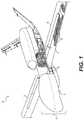
- FIG. 1is a diagrammatic illustration of an exemplary vehicle body
- FIG. 2-5are diagrammatic illustrations of exemplary portions of the vehicle body of FIG. 1 during manufacture
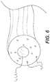
- FIG. 6is a cross-sectional illustration of an exemplary fiber that may be used to fabricate the vehicle body of FIG. 1 ;
- FIGS. 7 and 8are diagrammatic illustrations of additional exemplary portions of the vehicle body of FIG. 1 .
- FIG. 1illustrates an exemplary vehicle body (“body”) 10 .
- body 10is an aircraft body (e.g., an airplane body or a drone body). It is contemplated, however, that body 10 could be of another type (e.g., a car body, a boat body, etc.), if desired.
- Body 10regardless of its configuration and intended use, may include one or more components (e.g., a fuselage 12 , one or more wings 14 , etc.) made from an internal skeleton (e.g., spars, ribs, stringers, bulkheads, trusses, longerons, etc.) 16 covered by an external skin 18 .
- an internal skeletone.g., spars, ribs, stringers, bulkheads, trusses, longerons, etc.
- the components of body 10may be fabricated separately and subsequently joined together (e.g., via threaded fastening, riveting, etc.). In other embodiments, the body components may be fabricated together as an integral monolithic structure (e.g., a structure that cannot be disassembled without at least some destruction).
- skeleton 16may be fabricated from a first additive manufacturing process
- skin 18may be manufactured from a second and different additive manufacturing process. It is contemplated that both skeleton 16 and skin 18 could be manufactured from the same additive manufacturing process, if desired.
- the first additive manufacturing processmay be a pultrusion and/or extrusion process that creates hollow tubular structures 20 from a composite material (e.g., a material having a matrix M and at least one continuous fiber F).
- a composite materiale.g., a material having a matrix M and at least one continuous fiber F
- one or more heads 22may be coupled to a support 24 (e.g., to a robotic arm) that is capable of moving head(s) 22 in multiple directions during discharge of structures 20 , such that resulting longitudinal axes 26 of structures 20 are three-dimensional.
- a support 24e.g., to a robotic arm
- Such a headis disclosed, for example, in U.S. patent application Ser. Nos. 13/975,300 and 15/130,207 and in PCT Application Number 2016042909, all of which are incorporated herein in their entireties by reference.
- Head(s) 22may be configured to receive or otherwise contain the matrix material M.
- the matrix material Mmay include any type of liquid resin (e.g., a zero volatile organic compound resin) that is curable.
- Exemplary resinsinclude epoxy resins, polyester resins, cationic epoxies, acrylated epoxies, urethanes, esters, thermoplastics, photopolymers, polyepoxides, thermoset acrylates, thermosets, bismaleimides, silicon, and more.
- the pressure of the matrix material M inside of head(s) 22may be generated by an external device (e.g., an extruder or another type of pump) that is fluidly connected to head(s) 22 via corresponding conduits (not shown).
- the pressuremay be generated completely inside of head(s) 22 by a similar type of device and/or simply be the result of gravity acting on the matrix material M.
- the matrix material M inside head(s) 22may need to be kept cool and/or dark in order to inhibit premature curing; while in other instances, the matrix material M may need to be kept warm for the same reason.
- head(s) 22may be specially configured (e.g., insulated, chilled, and/or warmed) to provide for these needs.
- the matrix material M stored inside head(s) 22may be used to coat any number of continuous fibers F and, together with the fibers F, make up walls of composite structures 20 .
- the fibers Fmay include single strands, a tow or roving of several strands, or a weave of many strands.
- the strandsmay include, for example, carbon fibers, vegetable fibers, wood fibers, mineral fibers, glass fibers, metallic wires, SiC Ceramic fibers, basalt fibers, etc.
- the fibers Fmay be coated with the matrix material M while the fibers F are inside head(s) 22 , while the fibers F are being passed to head(s) 22 , and/or while the fibers F are discharging from head(s) 22 , as desired.
- a filler material(e.g., chopped fibers) may be mixed with the matrix material M before and/or after the matrix material M coats the fibers F.
- the matrix material, the dry fibers, fibers already coated with the matrix material M, and/or the fillermay be transported into head(s) 22 in any manner apparent to one skilled in the art.
- the matrix-coated fibers Fmay then pass over a centralized diverter (not shown) located at a mouth of head(s) 22 , where the resin is caused to cure (e.g., from the inside-out, from the outside-in, or both) by way of one or more cure enhancers (e.g., UV lights and/or ultrasonic emitters) 27 .
- cure enhancerse.g., UV lights and/or ultrasonic emitters
- structures 20extend in a length direction of wing 14 and makeup at least a portion of skeleton 16 .
- Each structure 20may be discharged adjacent another structure 20 and/or overlap a previously discharged structure 20 , and subsequently cured such that the liquid resin within neighboring structures 20 bonds together.
- Any number of structures 20may be grouped together and have any trajectory required to generate the desired skeletal shape of wing 14 .
- a fill materiale.g., an insulator, a conductor, an optic, a surface finish, etc.
- a fill materiale.g., an insulator, a conductor, an optic, a surface finish, etc.
- a hollow shaft(not shown) could extend through a center of and/or over any of the associated head(s) 22 .
- a supply of materiale.g., a liquid supply, a foam supply, a solid supply, a gas supply, etc.
- the materialforced through the hollow shaft and onto particular surfaces (i.e., interior and/or exterior surfaces) of structure 20 .
- cure enhancer(s) 27 used to cure structure 20could also be used to cure the fill material, if desired, or that additional dedicated cure enhancer(s) (not shown) could be used for this purpose.
- the fill materialscould allow one or more of structures 20 to function as fuel tanks, fuel passages, electrical conduits, ventilation ducts, etc.
- the second additive manufacturing process used to fabricate the exemplary wing 14 of FIG. 2may also be a pultrusion and/or extrusion process.
- the second additive manufacturing processmay be used to discharge tracks, ribbons, and/or sheets of composite material over tubular structures 20 (and/or over other features of skeleton 16 ) to thereby fabricate skin 18 .
- one or more heads 28may be coupled to a support 30 (e.g., to an overhead gantry) that is capable of moving head(s) 28 in multiple directions during fabrication of skin 18 , such that resulting contours of skin 18 are three-dimensional.
- Head 28may be similar to head 22 and configured to receive or otherwise contain a matrix material M (e.g., the same matrix material M contained within head 22 ).
- the matrix material M stored inside head(s) 28may be used to coat any number of separate fibers F, allowing the fibers F to make up centralized reinforcements of the discharging tracks, ribbons, and/or sheets.
- the fibers Fmay include single strands, a tow or roving of several strands, or a weave of multiple strands.
- the strandsmay include, for example, carbon fibers, vegetable fibers, wood fibers, mineral fibers, glass fibers, metallic wires, etc.
- the fibers Fmay be coated with the matrix material M while the fibers F are inside head(s) 28 , while the fibers F are being passed to head(s) 28 , and/or while the fibers F are discharging from head(s) 28 , as desired.
- the matrix material, the dry fibers, and/or fibers already coated with the matrix materialmay be transported into head(s) 28 in any manner apparent to one skilled in the art.
- the matrix-coated fibers Fmay then pass through one or more circular orifices, rectangular orifices, triangular orifices, or orifices of another curved or polygonal shape, where the fibers F are pressed together and the resin is caused to cure by way of one or more cure enhancers 27 .
- a single additive manufacturing processis being used to fabricate wing 14 .
- the second manufacturing process described aboveis being used to additively build up layers of skeleton 16 (e.g., of spars and/or stringers) with continuous fibers F and matrix material M and to cover skeleton 16 with additively built up layers of skin 18 of the same or different continuous fibers F and matrix material M.
- the fibers F making up skeleton 16may continue over an outer surface of skeleton 16 to become part of skin 18 , such that a continuous mechanical connection is formed between skeleton 16 and skin 18 by the continuous fibers F. In this way, the number of fasteners required to connect skin 18 to skeleton 16 may be reduced (if not eliminated).
- support 24 and/or support 30may be used to move any number of heads 28 during fabrication of wing 14 (or during fabrication of any other component of body 10 ).
- the first and second additive manufacturing processescan be extrusion or pultrusion processes.
- extrusionmay occur when the liquid resin matrix M and the associated continuous fibers F are pushed from head(s) 22 and/or head(s) 28 during the movement of supports 24 and/or 30 .
- Pultrusionmay occur after a length of resin-coated fibers is connected to an anchor (not shown) and cured, followed by movement of head(s) 22 and/or heads ( 28 ) away from the anchor. The movement of head(s) 22 and/or head(s) 28 away from the anchor causes the fibers F to be pulled from the respective head(s) along with the coating of the matrix material M.
- pultrusionmay be selectively implemented to generate tension in the fibers F that make up skeleton 16 and/or skin 18 and that remains after curing.
- the fibers Fmay be caused to stretch. This stretching can create tension within the fibers F. As long as the matrix M surrounding the fibers F cures and hardens while the fibers F are stretched, at least some of this tension remains in the fibers F and functions to increase a strength of the resulting composite structure.
- Structures fabricated via conventional pultrusion methodsmay have increased strength in only a single direction (e.g., in the one direction in which fibers were pulled through the corresponding die prior to manual resin impregnation and curing).
- the increased strength in the skeleton 16 and/or skin 18 of body 10e.g., within wing 14
- the tension-related strength increasemay be realized in multiple (e.g., innumerable) different directions.
- Structures fabricated via conventional pultrusion methodsmay have strength increased to only a single level (e.g., to a level proportionate to an amount in which the fibrous cloth was stretched by the pulling machine prior to manual resin impregnation and curing).
- the force pulling on the fiber Fmay be continuously varied along the length of the fiber F, such that different segments of the same fiber F are stretched by different amounts.
- the tensile stress induced within each of the different segments of each fiber Fmay also be different, resulting in a variable strength within the different segments of skeleton 16 and/or skin 18 of body 10 . This may be beneficial in variably loaded areas of body 10 (e.g., at the intersection of wing 14 and fuselage 12 , within a center of wing 14 , at the leading edge of wing 14 , etc.).
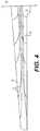
- FIG. 4illustrates an exemplary way in which the fibers F of skin 18 can be arranged to provide for desired characteristics of wing 14 .
- the fibers Fare arranged organically (e.g., in the way that a tree grows or in the way that blood veins are situated in the body).
- the fibers F placed over structure 16 of wing 14may be anchored at an intersection with fuselage 12 and in a general fore/aft center.
- the fibers Fmay then be pulled toward a distal tip of wing 14 , and away from the fore/aft center (e.g., toward a leading or trailing edge of wing 14 ), with different fibers F extending different distances toward the distal tip.
- the discharging matrix material Mmay cure immediately upon discharge from head 28 and bond to either structure 16 or previously discharged layers of skin 18 , movement of head 28 during discharge may be controlled to create trajectories of the fibers F that curve. It is contemplated that the fibers F may pass completely around wing 14 at its distal termination point, and then be pulled back toward fuselage 12 following a mirror image of its initial trajectory.
- This arrangement of organically arranged fibersmay be located at a top side of wing 14 , at a lower side, and/or around a cross-sectional perimeter of wing 14 at multiple locations. With this arrangement, a greater density of fibers F may exist near fuselage 12 than near the distal tip of wing 14 . Accordingly, wing 14 may be thicker near fuselage 12 and near the general fore/aft center, and taper toward the distal tip and the leading and trailing edges. Other arrangements and/or fiber distribution schemes may be employed, as desired.
- some of the fibers F within the composite material making up one or more portions of body 10have unique characteristics.
- a majority of wing 14may comprise a structural type fiber F s (e.g., carbon fibers, fiberglass, or Kevlar fibers)
- some portions of wing 14may include another type of fiber F (e.g., electrically conductive fibers F ec , optical fibers F o , shape memory fibers F sm , etc.).
- the other type of fibers Fmay be selectively interwoven with the structural type fibers F s at strategic locations.
- electrically conductive fibers F ecmay be located at leading edges and/or thinner portions of wing 14 and used as heating electrodes that can be connected to a power source and used to remove ice from wing 14 .
- electrically conductive fibers F ecmay be located at high-stress regions (e.g., at the intersection of wing 14 and fuselage 12 ) and used as strain gauges to detect loading of body 10 .
- optical fibers F omay be located at high-stress regions and an energy beam passed therethrough. As body 10 flexes, the optical fibers F o may be squeezed and/or closed, thereby generating an optical feedback signal indicative of the flexing.
- fibers F sm fabricated from a shape memory alloymay be interwoven with the structural type fibers F s and selectively energized (e.g., via electricity or heat) to cause flexing (e.g., controlled pulling and/or pushing) of body 10 that results in a desired aerodynamic performance (e.g., steering, orientation, elevation control, stability, drag, etc.).
- a desired aerodynamic performancee.g., steering, orientation, elevation control, stability, drag, etc.
- the electrically conductive fibers F ec , the optical fibers F o , and/or the shape memory fibers F smmay be coated with another material (e.g., insulation, a strength enhancing layer, etc.), if desired.
- Structures fabricated via conventional pultrusion and/or extrusion methodsmay be limited in the orientation of the associated fibers. That is, the fibers may be generally overlapping and lie in parallel layers. However, in the embodiment illustrated in FIG. 5 , because the matrix M surrounding each fiber F may be cured and harden immediately upon discharge, the fibers F may be caused to extend into free space without additional support. That is, the fibers F may not be required to lie in flat layers on top of each other. Accordingly, the fibers F making up skeleton 16 and/or skin 18 may be oriented in directions that are perpendicular to each other in three dimensions. For example, FIG. 5 illustrates fibers F n that extend in a direction normal to the surface of wing 14 . This may allow for interlocking of fiber layers and/or for the creation of unique (e.g., turbulence enhancing) surface textures.
- body 10may be fabricated as an integral monolithic structure, in some embodiments.
- wings 14may be fabricated together with (e.g., at the same time as and without separation from) fuselage 12 .
- head(s) 28may pass from one wing 14 , over or under fuselage 12 , and continue across the opposing wing 14 .
- the fibers F discharging from head(s) 28may be continuous over wings 14 and fuselage 12 . This process may be repeated any number of times, such that millions (if not hundreds of millions) of fibers F extend through the intersection between wings 14 and fuselage 12 , thereby creating a strong mechanical connection without requiring the use of specialized hardware and/or heavy fasteners.
- the matrix M within the composite material making up one or more portions of body 10has unique characteristics.
- a majority of wing 14may comprise a structural type matrix M s (e.g., a conventional UV curable liquid resin such as an acrylated epoxy)
- some portions of wing 14may include another type of matrix M (e.g., a pyrolized matrix M p , a matrix that remains somewhat flexible M f , etc.).
- the other type of matrix Mmay be selectively used to coat the fibers F at strategic locations.
- the pyrolized matrix M pmay be fed into head 28 as head 28 nears the leading edge of wing 14 and/or a nose of fuselage 12 , such that the resulting composite material may function as a heat shield in these areas.
- the flexible matrix M fmay be fed into head 28 as head 28 nears the trailing edge of wing 14 (e.g., where the shape memory fibers F sm are placed, such that the resulting composite material may be more flexible and selectively warped or twisted to provide for the desired aerodynamic properties described above.
- FIG. 7illustrates an exemplary part 32 of skeleton 16 that may be fabricated through the use of head 28 and support 30 .
- part 32could be another skeletal component of wing 14 and/or fuselage 12 .
- part 32includes opposing outer support surfaces 34 , opposing internal braces 36 , and a plurality of cross-pieces 38 that interconnect support surfaces 34 and/or braces 36 .
- outer support surfaces 34 and/or internal braces 36could have any desired shape, for example curved, flat, stepped, etc. It is also contemplated that outer support surfaces 34 and internal support surfaces 36 could form one or more continuous surfaces, if desired.
- one or more of support surfaces 34could be curved and generally tangential with one or more of braces 36 (e.g., at a leading and/or trailing end of the rib).
- cross-pieces 38are shown as generally straight and oriented at about 45° relative to support surfaces 34 and braces 36 , it is contemplated that cross-pieces 38 could also be curved and/or oriented at another angle. It should be noted that, although seven adjacent and nearly identical parts 32 are shown to make up the disclosed rib, any number of the same or different parts 32 (e.g., only one part 32 ) may be used for this purpose.
- Part 32may be created following a unique tool path that allows for use of continuous fibers and provides for high-strength in a low-weight configuration.
- part 32may be fabricated using a middle-out strategy.
- FIG. 8illustrates use of this strategy during fabrication using multiple different and overlapping layers.
- head 28may be controlled to start discharging and curing one or more continuous resin-coated fibers at a lower-left corner (e.g., adjacent an internal intersection of a lower support surface 34 and a left brace 36 ), and continue discharging and curing the same resin-coated fiber(s) during travel upward to an adjacent upper-left corner. Head 28 may then move diagonally inward toward a general center of part 32 , and then double back prior to reaching the center to move toward the upper-left corner following a generally parallel trajectory.
- a lower-left cornere.g., adjacent an internal intersection of a lower support surface 34 and a left brace 36
- head 28may be spaced apart a distance from its original trajectory (e.g., spaced more toward the right of part 32 ), such that an empty space will exist along a diagonal of part 32 and a box shape is formed at internal ends of the diagonal parallel tracks. Head 28 may then move rightward to an upper-right corner of part 32 , followed by about a 90° turn downward upon reaching an internal edge of part 32 . The same general pattern may be repeated at the lower-right corner of part 32 that was made at the upper-left corner, such that a mirror image across a virtual diagonal dividing line is created. Head 28 may then move leftward and stop short of its starting point, after which head 28 may turn through about 45° clockwise and travel diagonally completely across part 32 to the upper-right corner.
- Head 28may then double back toward the lower-left corner along a spaced-apart parallel track, such that head 28 is near its starting point (e.g., radially outward and slightly lower than the starting point).
- head 28may be spaced apart a distance from its original trajectory (e.g., spaced more toward the left of part 32 ), such that an empty space will exist along a diagonal of part 32 .
- head 28may deviate from its trajectory at a turn-around point and head into the corner, such that an arrow-head shape is formed at internal ends of the parallel tracks.
- the arrow-head shapemay bond to the hardened fibers laid down previously at this corner location.
- the diagonally laid fiber(s)may bond to the box shape previously laid down at the center of part 32 .
- the entire processmay be repeated any number of times to add a corresponding number of material tracks to the first layer and thereby increase a cross-sectional area of the first layer.
- part 32may grow outward and the empty spaces described above as being located between the parallel tracks may be filled in.
- the fibers discharging from head 28may not overlap other fibers such that all fibers are laid down within the same plane.
- the fiber(s)may be cut from head 28 , such that head 28 may be repositioned for start of a new layer.
- a second layermay be formed directly on top of the first layer, for example by rotating the pattern of the first layer through a desired angle (e.g., through about 90°). By rotating the pattern through about 90°, the fibers extending diagonally completely across part 32 in the second layer may overlap the fibers that doubled back at the center of part 32 in the first layer. This overlapping of different portions of the repeating pattern may help to increase a strength of part 32 . It is contemplated that any number of fibers may be deposited at any location and oriented generally normal to the overlapping layers (e.g., fibers F n like those shown in FIG. 5 ) to interlock the layers, if desired. Additionally or alternatively, discharged but uncured portions of a previous layer could be wrapped over subsequently formed layers and then cured to improve an interlock strength.
- a desired anglee.g., through about 90°
- any number of additional layersmay be formed on top of the first two layers in alternating orientations and/or in orientations of incremental rotating angles (e.g., when the angle is not a multiple of 90°). This may continue until a desired thickness of part 32 is achieved.
- an entire fuselage 12 and/or wing 14could be fabricated in this manner.
- skin 18could be simultaneously fabricated over part 32 when using the middle-out approach.
- an empty spacemay be created inside of fuselage 12 and/or wing 14 and between adjacent parts 32 , by only creating outer portions of supports 34 and/or braces 36 .
- skeleton 16 and skin 18may be used in connection with any type of vehicle body 10 .
- skeleton 16 and skin 18may be used in connection with an airplane body, a drone body, a car body, a boat body, or any other type of vehicle body where light-weight, low-cost, and high-performance are important.
- Vehicle body 10may be light-weight and low-cost due to the reduction in the number of fasteners required to secure skin 18 to skeleton 16 and/or to secure components of vehicle body 10 to each other.
- vehicle body 10may be light-weight do to the use of composite materials used to make both of skeleton 16 and skin 18 .
- the high-performancemay be provided in the unique ways that particular fibers and resins are used and laid out within skeleton 16 and skin 18 .
Landscapes
- Engineering & Computer Science (AREA)
- Mechanical Engineering (AREA)
- Chemical & Material Sciences (AREA)
- Aviation & Aerospace Engineering (AREA)
- Materials Engineering (AREA)
- Manufacturing & Machinery (AREA)
- Physics & Mathematics (AREA)
- Optics & Photonics (AREA)
- Composite Materials (AREA)
- Transportation (AREA)
- Robotics (AREA)
- Architecture (AREA)
- Structural Engineering (AREA)
- Civil Engineering (AREA)
- Mathematical Physics (AREA)
- Life Sciences & Earth Sciences (AREA)
- Wood Science & Technology (AREA)
- Textile Engineering (AREA)
- Moulding By Coating Moulds (AREA)
- Laminated Bodies (AREA)
- Diaphragms For Electromechanical Transducers (AREA)
Abstract
Description
Claims (15)
Priority Applications (11)
| Application Number | Priority Date | Filing Date | Title |
|---|---|---|---|
| US15/682,826US10717512B2 (en) | 2016-11-03 | 2017-08-22 | Composite vehicle body |
| AU2017353865AAU2017353865B2 (en) | 2016-11-03 | 2017-11-02 | Composite vehicle body |
| CA3039799ACA3039799A1 (en) | 2016-11-03 | 2017-11-02 | Composite vehicle body |
| RU2019116894ARU2019116894A (en) | 2016-11-03 | 2017-11-02 | VEHICLE BODY MADE OF COMPOSITE MATERIAL |
| PCT/US2017/059778WO2018085579A1 (en) | 2016-11-03 | 2017-11-02 | Composite vehicle body |
| EP21152367.5AEP3827974A1 (en) | 2016-11-03 | 2017-11-02 | Composite vehicle body |
| EP17867395.0AEP3535113A4 (en) | 2016-11-03 | 2017-11-02 | Composite vehicle body |
| KR1020197012814AKR102211611B1 (en) | 2016-11-03 | 2017-11-02 | Composite vehicle body |
| JP2019520356AJP6829311B2 (en) | 2016-11-03 | 2017-11-02 | Composite vehicle body |
| CN201780067648.2ACN109922945B (en) | 2016-11-03 | 2017-11-02 | composite vehicle body |
| AU2022231803AAU2022231803A1 (en) | 2016-11-03 | 2022-09-19 | Composite vehicle body |
Applications Claiming Priority (2)
| Application Number | Priority Date | Filing Date | Title |
|---|---|---|---|
| US201662417056P | 2016-11-03 | 2016-11-03 | |
| US15/682,826US10717512B2 (en) | 2016-11-03 | 2017-08-22 | Composite vehicle body |
Publications (2)
| Publication Number | Publication Date |
|---|---|
| US20180118324A1 US20180118324A1 (en) | 2018-05-03 |
| US10717512B2true US10717512B2 (en) | 2020-07-21 |
Family
ID=62020221
Family Applications (6)
| Application Number | Title | Priority Date | Filing Date |
|---|---|---|---|
| US15/682,835Expired - Fee RelatedUS10766594B2 (en) | 2016-11-03 | 2017-08-22 | Composite vehicle body |
| US15/682,818Expired - Fee RelatedUS10773783B2 (en) | 2016-11-03 | 2017-08-22 | Composite vehicle body |
| US15/682,844Expired - Fee RelatedUS10766595B2 (en) | 2016-11-03 | 2017-08-22 | Composite vehicle body |
| US15/682,826Expired - Fee RelatedUS10717512B2 (en) | 2016-11-03 | 2017-08-22 | Composite vehicle body |
| US15/697,483Expired - Fee RelatedUS10787240B2 (en) | 2016-11-03 | 2017-09-07 | Composite vehicle body |
| US16/947,661ActiveUS11383819B2 (en) | 2016-11-03 | 2020-08-11 | Composite vehicle body |
Family Applications Before (3)
| Application Number | Title | Priority Date | Filing Date |
|---|---|---|---|
| US15/682,835Expired - Fee RelatedUS10766594B2 (en) | 2016-11-03 | 2017-08-22 | Composite vehicle body |
| US15/682,818Expired - Fee RelatedUS10773783B2 (en) | 2016-11-03 | 2017-08-22 | Composite vehicle body |
| US15/682,844Expired - Fee RelatedUS10766595B2 (en) | 2016-11-03 | 2017-08-22 | Composite vehicle body |
Family Applications After (2)
| Application Number | Title | Priority Date | Filing Date |
|---|---|---|---|
| US15/697,483Expired - Fee RelatedUS10787240B2 (en) | 2016-11-03 | 2017-09-07 | Composite vehicle body |
| US16/947,661ActiveUS11383819B2 (en) | 2016-11-03 | 2020-08-11 | Composite vehicle body |
Country Status (9)
| Country | Link |
|---|---|
| US (6) | US10766594B2 (en) |
| EP (2) | EP3535113A4 (en) |
| JP (1) | JP6829311B2 (en) |
| KR (1) | KR102211611B1 (en) |
| CN (1) | CN109922945B (en) |
| AU (2) | AU2017353865B2 (en) |
| CA (1) | CA3039799A1 (en) |
| RU (1) | RU2019116894A (en) |
| WO (1) | WO2018085579A1 (en) |
Cited By (1)
| Publication number | Priority date | Publication date | Assignee | Title |
|---|---|---|---|---|
| US20230046113A1 (en)* | 2020-01-23 | 2023-02-16 | Bae Systems Plc | Airframe and method for assembling an airframe |
Families Citing this family (37)
| Publication number | Priority date | Publication date | Assignee | Title |
|---|---|---|---|---|
| US10766594B2 (en)* | 2016-11-03 | 2020-09-08 | Continuous Composites Inc. | Composite vehicle body |
| US10987871B2 (en)* | 2017-03-08 | 2021-04-27 | General Atomics Aeronautical Systems, Inc. | Systems and methods for tool-less manufacturing of thermoplastic parts |
| WO2019029979A1 (en)* | 2017-08-11 | 2019-02-14 | Philips Lighting Holding B.V. | Method for manufacturing a 3d item having an electrically conductive coil |
| DE102017130884B4 (en)* | 2017-12-21 | 2019-08-14 | Airbus Defence and Space GmbH | Aircraft and method of manufacturing an aircraft |
| US10745104B2 (en)* | 2018-03-02 | 2020-08-18 | The Boeing Company | Stringer transition through a common base charge |
| US10647407B2 (en)* | 2018-03-30 | 2020-05-12 | The Boeing Company | Wing flap with torque member and method for forming thereof |
| US10597141B2 (en)* | 2018-03-30 | 2020-03-24 | The Boeing Company | Wing flap with torque member and method for forming thereof |
| DE102018215356B4 (en)* | 2018-09-10 | 2024-02-15 | Airbus Operations Gmbh | Method for producing a fuselage component for an aircraft |
| CN109572003B (en)* | 2018-11-27 | 2020-12-29 | 航天特种材料及工艺技术研究所 | A molding die and method for in-situ molding of insulating material components on cabin sections |
| FR3094664B1 (en)* | 2019-04-05 | 2022-03-11 | Faurecia Interieur Ind | Process for manufacturing a skin of variable property |
| DE102019003450A1 (en)* | 2019-05-16 | 2020-05-14 | Diehl Aviation Laupheim Gmbh | Commiedied yarn on a plastic component |
| US12365134B2 (en)* | 2019-06-10 | 2025-07-22 | Peridot Print Llc | Three-dimensional printing |
| US11814324B2 (en) | 2019-07-18 | 2023-11-14 | Northrop Grumman Systems Corporation | Additive manufacturing methods for forming high-temperature composite structures and related structures |
| US11046420B2 (en)* | 2019-10-23 | 2021-06-29 | The Boeing Company | Trailing edge flap having a waffle grid interior structure |
| US11851178B2 (en)* | 2020-02-14 | 2023-12-26 | The Aerospace Corporation | Long range endurance aero platform system |
| DE102020108836B4 (en) | 2020-03-31 | 2024-08-22 | Technische Universität Dresden, Körperschaft des öffentlichen Rechts | ACTUATOR ARRANGEMENT, WIPER DEVICE FOR WIPE A VEHICLE WINDOW AND WIPER DEVICE FOR USE ON A VEHICLE |
| FR3109369B1 (en) | 2020-04-20 | 2024-04-12 | Bruno Trapletti | Process for manufacturing an aircraft and aircraft obtained by its implementation |
| US11572152B2 (en) | 2020-05-21 | 2023-02-07 | The Boeing Company | Structural composite airfoils with a single spar, and related methods |
| US11554848B2 (en)* | 2020-05-21 | 2023-01-17 | The Boeing Company | Structural composite airfoils with a single spar, and related methods |
| US11453476B2 (en) | 2020-05-21 | 2022-09-27 | The Boeing Company | Structural composite airfoils with an improved leading edge, and related methods |
| US11401026B2 (en) | 2020-05-21 | 2022-08-02 | The Boeing Company | Structural composite airfoils with a single spar, and related methods |
| KR102380247B1 (en)* | 2020-05-28 | 2022-03-30 | 조남석 | Unmanned aerial vehicle |
| FR3111590B1 (en)* | 2020-06-23 | 2022-08-19 | Dassault Aviat | GAS TANK INTENDED TO SERVE AS A STRUCTURAL ELEMENT OF THE FUSELAGE, TAIL PAGE OR WING OF AN AIRCRAFT |
| CN111792020B (en)* | 2020-07-17 | 2022-07-08 | 哈尔滨工业大学(威海) | A SMA-driven folding umbrella-wing UAV |
| WO2022070121A1 (en)* | 2020-10-02 | 2022-04-07 | Yam Tech S.R.L. | A method for producing a shell-like or plate like supporting structure |
| US20220126508A1 (en)* | 2020-10-23 | 2022-04-28 | Continuous Composites Inc. | Print head for additive manufacturing system |
| CN112158323B (en)* | 2020-10-24 | 2024-06-21 | 西安航空学院 | Unmanned aerial vehicle fuselage-heat dissipation intake duct 3D additive integrated skin structure |
| CN112173163B (en)* | 2020-10-24 | 2025-04-25 | 西安航空学院 | A manufacturing process for 3D additive matrix composite skin of unmanned aerial vehicle |
| CN114771802A (en) | 2021-01-22 | 2022-07-22 | 波音公司 | Aerodynamic structure and method of forming an aerodynamic structure |
| US11597490B1 (en)* | 2021-12-22 | 2023-03-07 | Rapidflight Holdings, Llc | Additive manufactured airframe structure having a plurality of reinforcement elements |
| US12151812B2 (en)* | 2022-02-02 | 2024-11-26 | Rohr, Inc. | Resin pressure molded aerostructure with integrated metal coupling |
| DE102022116949A1 (en) | 2022-07-07 | 2024-01-18 | Airbus Operations Gmbh | Wing for an aircraft |
| DE102022119683B4 (en) | 2022-08-05 | 2025-03-20 | Dr. Ing. H.C. F. Porsche Aktiengesellschaft | Vehicle device and vehicle |
| PL443923A1 (en)* | 2023-02-28 | 2024-09-02 | Air-Concept Spółka Z Ograniczoną Odpowiedzialnością | Method for producing an aircraft fuselage |
| CN116280331A (en)* | 2023-03-28 | 2023-06-23 | 西安交通大学 | A continuous fiber reinforced composite UAV wing and 3D printing manufacturing method |
| GB2629401B (en)* | 2023-04-27 | 2025-06-11 | Silverstone Performance Tech Limited | A method for forming a structual element for a vehicle |
| CN118597403B (en)* | 2024-07-31 | 2024-12-06 | 江苏亨睿航空工业有限公司 | Wing structure and preparation method thereof |
Citations (181)
| Publication number | Priority date | Publication date | Assignee | Title |
|---|---|---|---|---|
| US3286305A (en) | 1964-09-03 | 1966-11-22 | Rexall Drug Chemical | Apparatus for continuous manufacture of hollow articles |
| US3809514A (en) | 1971-11-13 | 1974-05-07 | Castro Nunez Elem Huecos | Machine for the continuous manufacture of hollow elements |
| US3984271A (en) | 1973-06-25 | 1976-10-05 | Owens-Corning Fiberglas Corporation | Method of manufacturing large diameter tubular structures |
| US3993726A (en) | 1974-01-16 | 1976-11-23 | Hercules Incorporated | Methods of making continuous length reinforced plastic articles |
| US4079903A (en)* | 1971-04-19 | 1978-03-21 | Fiber Science, Inc. | Lightweight contoured load carrying structure |
| US4538780A (en)* | 1983-09-26 | 1985-09-03 | The Boeing Company | Ultralight composite wing structure |
| US4643940A (en) | 1984-08-06 | 1987-02-17 | The Dow Chemical Company | Low density fiber-reinforced plastic composites |
| US4671761A (en) | 1984-06-30 | 1987-06-09 | Fried. Krupp Gesellschaft Mit Beschrankter Haftung | Apparatus for producing reinforced elongate bodies |
| US4822548A (en) | 1986-06-13 | 1989-04-18 | Firma Carl Freudenberg | Method and apparatus for manufacturing a thread-reinforced rubber hose |
| US4851065A (en) | 1986-01-17 | 1989-07-25 | Tyee Aircraft, Inc. | Construction of hollow, continuously wound filament load-bearing structure |
| US5002712A (en) | 1988-10-19 | 1991-03-26 | Bayer Aktiengesellschaft | Manufacturing composite materials |
| US5037691A (en) | 1986-09-15 | 1991-08-06 | Compositech, Ltd. | Reinforced plastic laminates for use in the production of printed circuit boards and process for making such laminates and resulting products |
| DE4102257A1 (en) | 1991-01-23 | 1992-07-30 | Artos Med Produkte | Appts. for mfg. reinforced components in laser-cured polymer - has laser-curable polymer in bath, laser directed at polymer surface where fibres pass through polymer and are guided relative to laser beam angle |
| US5296335A (en) | 1993-02-22 | 1994-03-22 | E-Systems, Inc. | Method for manufacturing fiber-reinforced parts utilizing stereolithography tooling |
| US5340433A (en) | 1989-10-30 | 1994-08-23 | Stratasys, Inc. | Modeling apparatus for three-dimensional objects |
| US5440193A (en) | 1990-02-27 | 1995-08-08 | University Of Maryland | Method and apparatus for structural, actuation and sensing in a desired direction |
| US5746967A (en) | 1995-06-26 | 1998-05-05 | Fox Lite, Inc. | Method of curing thermoset resin with visible light |
| US5866058A (en) | 1997-05-29 | 1999-02-02 | Stratasys Inc. | Method for rapid prototyping of solid models |
| US5936861A (en) | 1997-08-15 | 1999-08-10 | Nanotek Instruments, Inc. | Apparatus and process for producing fiber reinforced composite objects |
| US6153034A (en) | 1997-08-03 | 2000-11-28 | Micromod R.P. Ltd | Rapid prototyping |
| US20020009935A1 (en) | 1999-03-23 | 2002-01-24 | Hexcel Corporation | Core-crush resistant fabric and prepreg for fiber reinforced composite sandwich structures |
| US20020062909A1 (en) | 2000-11-29 | 2002-05-30 | Jang Bor Z. | Layer-additive method and apparatus for freeform fabrication of 3-D objects |
| US20020113331A1 (en) | 2000-12-20 | 2002-08-22 | Tan Zhang | Freeform fabrication method using extrusion of non-cross-linking reactive prepolymers |
| US6459069B1 (en) | 1996-11-22 | 2002-10-01 | Joshua E. Rabinovich | Rapid manufacturing system for metal, metal matrix composite materials and ceramics |
| US20020165304A1 (en) | 2000-12-04 | 2002-11-07 | Mulligan Anthony C. | Methods and appratus for preparation of three-dimensional bodies |
| US6501554B1 (en) | 2000-06-20 | 2002-12-31 | Ppt Vision, Inc. | 3D scanner and method for measuring heights and angles of manufactured parts |
| US20030044539A1 (en) | 2001-02-06 | 2003-03-06 | Oswald Robert S. | Process for producing photovoltaic devices |
| US20030056870A1 (en) | 2001-09-21 | 2003-03-27 | Stratasys, Inc. | High-precision modeling filament |
| US20030146346A1 (en)* | 2002-12-09 | 2003-08-07 | Chapman Jr W. Cullen | Tubular members integrated to form a structure |
| US20030160970A1 (en) | 2002-01-30 | 2003-08-28 | Anup Basu | Method and apparatus for high resolution 3D scanning |
| US20030186042A1 (en) | 2002-05-07 | 2003-10-02 | Dunlap Earl N. | Process for tempering rapid prototype parts |
| US20030236588A1 (en) | 2002-03-14 | 2003-12-25 | Jang Bor Z. | Nanotube fiber reinforced composite materials and method of producing fiber reinforced composites |
| US6799081B1 (en) | 2000-11-15 | 2004-09-28 | Mcdonnell Douglas Corporation | Fiber placement and fiber steering systems and corresponding software for composite structures |
| US6803003B2 (en) | 2000-12-04 | 2004-10-12 | Advanced Ceramics Research, Inc. | Compositions and methods for preparing multiple-component composite materials |
| US20050006803A1 (en) | 2001-05-17 | 2005-01-13 | Owens Charles R. | Preform for manufacturing a material having a plurality of voids and method of making the same |
| US20050061422A1 (en) | 2003-09-22 | 2005-03-24 | Martin James P. | Multiple tape laying apparatus and method |
| US20050104257A1 (en) | 2003-09-04 | 2005-05-19 | Peihua Gu | Multisource and multimaterial freeform fabrication |
| US20050109451A1 (en) | 2003-11-20 | 2005-05-26 | Hauber David E. | Composite tape laying apparatus and method |
| US20050230029A1 (en) | 2001-01-02 | 2005-10-20 | Advanced Ceramics Research, Inc. | Continuous fiber reinforced composites and methods, apparatuses, and compositions for making the same |
| US7039485B2 (en) | 2004-03-12 | 2006-05-02 | The Boeing Company | Systems and methods enabling automated return to and/or repair of defects with a material placement machine |
| US20070003650A1 (en) | 2001-03-01 | 2007-01-04 | Schroeder Ernest C | Apparatus for fabricating fiber reinforced plastic parts |
| US20070228592A1 (en) | 2006-04-03 | 2007-10-04 | Stratasys, Inc. | Auto tip calibration in an extrusion apparatus |
| WO2008147754A1 (en) | 2007-05-23 | 2008-12-04 | The Boeing Company | Hybrid composite material having damping generating metallic fibers and method for making the same |
| US20090095410A1 (en) | 2007-10-16 | 2009-04-16 | Ingersoll Machine Tools, Inc. | Fiber Placement Machine Platform System Having Interchangeable Head and Creel Assemblies |
| US7555404B2 (en) | 2007-08-09 | 2009-06-30 | The Boeing Company | Methods and systems for automated ply boundary and orientation inspection |
| US7681835B2 (en)* | 1999-11-18 | 2010-03-23 | Rocky Mountain Composites, Inc. | Single piece co-cure composite wing |
| US7795349B2 (en) | 1999-11-05 | 2010-09-14 | Z Corporation | Material systems and methods of three-dimensional printing |
| KR100995983B1 (en) | 2008-07-04 | 2010-11-23 | 재단법인서울대학교산학협력재단 | Cross-printing method and apparatus of circuit board |
| US20100319838A1 (en) | 2005-02-04 | 2010-12-23 | Booher Benjamin V | Method of manufacture of pultruded non-metallic damage-tolerant hard ballistic laminate |
| US20110032301A1 (en) | 2004-09-21 | 2011-02-10 | Z Corporation | Apparatus and methods for servicing 3d printers |
| US20110143108A1 (en) | 2008-05-09 | 2011-06-16 | Fit Fruth Innovative Technologien Gmbh | Fibers and methods for use in solid freeform fabrication |
| US20120060468A1 (en) | 2010-09-13 | 2012-03-15 | Experimental Propulsion Lab, Llc | Additive manufactured propulsion system |
| US20120164907A1 (en) | 2010-12-28 | 2012-06-28 | Cytec Technology Corp. | Multilayer and composition gradient structures with improved damping properties |
| US20120159785A1 (en) | 2009-09-04 | 2012-06-28 | BayerMaerialScience LLC | Automated processes for the production of polyurethane wind turbine blades |
| US8221669B2 (en) | 2009-09-30 | 2012-07-17 | Stratasys, Inc. | Method for building three-dimensional models in extrusion-based digital manufacturing systems using ribbon filaments |
| KR101172859B1 (en) | 2010-10-04 | 2012-08-09 | 서울대학교산학협력단 | Ultra precision machining apparatus using nano-scale three dimensional printing and method using the same |
| US20120231225A1 (en) | 2010-09-17 | 2012-09-13 | Stratasys, Inc. | Core-shell consumable materials for use in extrusion-based additive manufacturing systems |
| US20120247655A1 (en) | 2009-11-13 | 2012-10-04 | Karlsruher Institut Fuer Technologie | Method for producing a component from a fiber-reinforced material |
| WO2013017284A2 (en) | 2011-08-04 | 2013-02-07 | Arburg Gmbh + Co. Kg | Method and device for producing a three-dimensional object comprising a fiber feed |
| US20130149521A1 (en) | 2010-06-22 | 2013-06-13 | Ticona Llc | Method for Forming Reinfoced Pultruded Profiles |
| US20130164498A1 (en) | 2011-12-21 | 2013-06-27 | Adc Acquisition Company | Thermoplastic composite prepreg for automated fiber placement |
| US20130209600A1 (en) | 2012-02-10 | 2013-08-15 | Adam Perry Tow | Multi-axis, multi-purpose robotics automation and quality adaptive additive manufacturing |
| US20130233471A1 (en) | 2012-03-08 | 2013-09-12 | Randall A. Kappesser | Small flat composite placement system |
| US20130292039A1 (en) | 2012-04-04 | 2013-11-07 | Massachusetts Institute Of Technology | Methods and Apparatus for Actuated Fabricator |
| US20130337265A1 (en) | 2012-06-19 | 2013-12-19 | EADS UK Limited British | Thermoplastic polymer powder |
| US20130337256A1 (en) | 2012-06-19 | 2013-12-19 | Eads Uk Limited | Extrusion-based additive manufacturing system |
| US20140034214A1 (en) | 2012-07-31 | 2014-02-06 | Makerbot Industries, Llc | Build material switching |
| US20140061974A1 (en) | 2012-08-29 | 2014-03-06 | Kenneth Tyler | Method and apparatus for continuous composite three-dimensional printing |
| US20140159284A1 (en) | 2012-12-07 | 2014-06-12 | Stratasys, Inc. | Liquefier assembly for use in additive manufacturing system |
| US20140232035A1 (en) | 2013-02-19 | 2014-08-21 | Hemant Bheda | Reinforced fused-deposition modeling |
| US20140268604A1 (en) | 2013-03-14 | 2014-09-18 | Board Of Regents, The University Of Texas System | Methods and Systems For Embedding Filaments in 3D Structures, Structural Components, and Structural Electronic, Electromagnetic and Electromechanical Components/Devices |
| US20140291886A1 (en) | 2013-03-22 | 2014-10-02 | Gregory Thomas Mark | Three dimensional printing |
| US8962717B2 (en) | 2012-08-20 | 2015-02-24 | Basf Se | Long-fiber-reinforced flame-retardant polyesters |
| US20150136455A1 (en) | 2013-11-15 | 2015-05-21 | Robert J. Fleming | Shape forming process and application thereof for creating structural elements and designed objects |
| US9126365B1 (en) | 2013-03-22 | 2015-09-08 | Markforged, Inc. | Methods for composite filament fabrication in three dimensional printing |
| US9126367B1 (en) | 2013-03-22 | 2015-09-08 | Markforged, Inc. | Three dimensional printer for fiber reinforced composite filament fabrication |
| US9149988B2 (en) | 2013-03-22 | 2015-10-06 | Markforged, Inc. | Three dimensional printing |
| US9156205B2 (en) | 2013-03-22 | 2015-10-13 | Markforged, Inc. | Three dimensional printer with composite filament fabrication |
| US9186848B2 (en) | 2013-03-22 | 2015-11-17 | Markforged, Inc. | Three dimensional printing of composite reinforced structures |
| US9186846B1 (en) | 2013-03-22 | 2015-11-17 | Markforged, Inc. | Methods for composite filament threading in three dimensional printing |
| US20160012935A1 (en) | 2014-07-11 | 2016-01-14 | Empire Technology Development Llc | Feedstocks for additive manufacturing and methods for their preparation and use |
| EP2589481B1 (en) | 2011-11-04 | 2016-01-20 | Ralph Peter Hegler | Device for continuously manufacturing a composite pipe with connection sleeve |
| US20160031155A1 (en) | 2014-07-29 | 2016-02-04 | Cc3D Llc | Method and Apparatus for Additive Mechanical Growth of Tubular Structures |
| US20160046082A1 (en) | 2014-08-12 | 2016-02-18 | Airbus Operations Gmbh | Apparatus and method for manufacturing components from a fiber-reinforced composite material |
| US20160052208A1 (en) | 2014-08-21 | 2016-02-25 | Mosaic Manufacturing Ltd. | Series enabled multi-material extrusion technology |
| US20160082641A1 (en) | 2014-09-18 | 2016-03-24 | The Boeing Company | Extruded Deposition of Fiber Reinforced Polymers |
| US20160082659A1 (en) | 2014-09-18 | 2016-03-24 | The Boeing Company | Extruded Deposition of Polymers Having Continuous Carbon Nanotube Reinforcements |
| US20160107379A1 (en) | 2013-03-22 | 2016-04-21 | Markforged, Inc. | Composite filament 3d printing using complementary reinforcement formations |
| US20160114532A1 (en) | 2013-05-31 | 2016-04-28 | United Technologies Corporation | Continuous fiber-reinforced component fabrication |
| US20160136885A1 (en) | 2014-11-14 | 2016-05-19 | Cole Nielsen-Cole | Additive manufacturing techniques and systems to form composite materials |
| WO2016088042A1 (en) | 2014-12-01 | 2016-06-09 | Sabic Global Technologies B.V. | Additive manufacturing process automation systems and methods |
| WO2016088048A1 (en) | 2014-12-01 | 2016-06-09 | Sabic Global Technologies B.V. | Rapid nozzle cooling for additive manufacturing |
| US9370896B2 (en) | 2013-06-05 | 2016-06-21 | Markforged, Inc. | Methods for fiber reinforced additive manufacturing |
| US9381702B2 (en) | 2013-03-15 | 2016-07-05 | Seriforge Inc. | Composite preforms including three-dimensional interconnections |
| US20160192741A1 (en) | 2015-01-05 | 2016-07-07 | Markforged, Inc. | Footwear fabrication by composite filament 3d printing |
| WO2016110444A1 (en) | 2015-01-09 | 2016-07-14 | Daher Aerospace | Method for producing a complex composite part, in particular having a thermoplastic matrix, and part obtained by such a method |
| US20160243762A1 (en) | 2013-11-15 | 2016-08-25 | Fleming Robert J | Automated design, simulation, and shape forming process for creating structural elements and designed objects |
| US20160263823A1 (en) | 2015-03-09 | 2016-09-15 | Frederick Matthew Espiau | 3d printed radio frequency absorber |
| US20160263822A1 (en) | 2013-10-30 | 2016-09-15 | R. Platt Boyd, IV | Additive manufacturing of building and other structures |
| US20160263806A1 (en) | 2013-10-30 | 2016-09-15 | Laing O'rourke Australia Pty Limited | Method for fabricating an object |
| US20160271876A1 (en) | 2015-03-22 | 2016-09-22 | Robert Bruce Lower | Apparatus and method of embedding cable in 3D printed objects |
| US9457521B2 (en) | 2011-09-01 | 2016-10-04 | The Boeing Company | Method, apparatus and material mixture for direct digital manufacturing of fiber reinforced parts |
| US9458955B2 (en) | 2012-07-20 | 2016-10-04 | Mag Aerospace Industries, Llc | Composite waste and water transport elements and methods of manufacture for use on aircraft |
| WO2016159259A1 (en) | 2015-03-31 | 2016-10-06 | キョーラク株式会社 | Filament resin molding, three-dimensional object fabrication method, and filament resin molding manufacturing method |
| US20160297104A1 (en) | 2013-11-19 | 2016-10-13 | Guill Tool & Engineering | Coextruded, multilayer and multicomponent 3d printing inputs field |
| US20160311165A1 (en) | 2013-03-22 | 2016-10-27 | Markforged, Inc. | Multiaxis fiber reinforcement for 3d printing |
| US20160325491A1 (en) | 2013-12-26 | 2016-11-10 | Texas Tech University System | Microwave-induced localized heating of cnt filled polymer composites for enhanced inter-bead diffusive bonding of fused filament fabricated parts |
| US20160332369A1 (en) | 2014-02-04 | 2016-11-17 | Samir Shah | Device and method of manufacturing customizable three-dimensional objects |
| US20160339633A1 (en) | 2014-01-17 | 2016-11-24 | Graphene 3D Lab Inc. | Fused filament fabrication using multi-segment filament |
| WO2016196382A1 (en) | 2015-06-01 | 2016-12-08 | Velo3D, Inc. | Three-dimensional printing and three-dimensional objects formed using the same |
| US20160361869A1 (en) | 2013-03-22 | 2016-12-15 | Markforged, Inc. | Three dimensional printer for fiber reinforced composite filament fabrication |
| US20160368255A1 (en) | 2015-06-19 | 2016-12-22 | Airbus Operations Gmbh | Method of manufacturing components, in particular elongated profile sections from band-shaped pre-impregnated fibers (prepreg) |
| US9539762B2 (en) | 2013-03-22 | 2017-01-10 | Markforged, Inc. | 3D printing with kinematic coupling |
| US20170007361A1 (en) | 2015-07-07 | 2017-01-12 | Align Technology, Inc. | Multi-material aligners |
| US20170007386A1 (en) | 2015-07-07 | 2017-01-12 | Align Technology, Inc. | Systems, apparatuses and methods for substance delivery from dental appliance |
| US20170007365A1 (en) | 2015-07-07 | 2017-01-12 | Align Technology, Inc. | Direct fabrication of aligners with interproximal force coupling |
| US20170007363A1 (en) | 2015-07-07 | 2017-01-12 | Align Technology, Inc. | Direct fabrication of power arms |
| US20170007362A1 (en) | 2015-07-07 | 2017-01-12 | Align Technology, Inc. | Dental materials using thermoset polymers |
| US20170007367A1 (en) | 2015-07-07 | 2017-01-12 | Align Technology, Inc. | Direct fabrication of aligners for palate expansion and other applications |
| WO2017006178A1 (en) | 2015-07-07 | 2017-01-12 | Align Technology, Inc. | Systems, apparatuses and methods for substance delivery from dental appliances and for ornamental designs on dental appliances |
| WO2017006324A1 (en) | 2015-07-09 | 2017-01-12 | Something3D Ltd. | Method and apparatus for three dimensional printing |
| US20170015059A1 (en) | 2015-07-17 | 2017-01-19 | Lawrence Livermore National Securty, Llc | High performance, rapid thermal/uv curing epoxy resin for additive manufacturing of short and continuous carbon fiber epoxy composites |
| US20170015060A1 (en) | 2015-07-17 | 2017-01-19 | Lawrence Livermore National Security, Llc | Additive manufacturing continuous filament carbon fiber epoxy composites |
| US20170021565A1 (en) | 2014-04-30 | 2017-01-26 | Magna International Inc. | Apparatus and process for forming three-dimensional objects |
| US20170028625A1 (en) | 2015-07-31 | 2017-02-02 | The Boeing Company | Systems and methods for additively manufacturing composite parts |
| US20170030207A1 (en) | 2015-07-28 | 2017-02-02 | General Electric Company | Ply, method for manufacturing ply, and method for manufacturing article with ply |
| US20170028644A1 (en) | 2015-07-31 | 2017-02-02 | The Boeing Company | Systems and methods for additively manufacturing composite parts |
| US20170028623A1 (en) | 2015-07-31 | 2017-02-02 | The Boeing Company | Systems and methods for additively manufacturing composite parts |
| US20170028628A1 (en) | 2015-07-31 | 2017-02-02 | The Boeing Company | Systems and methods for additively manufacturing composite parts |
| US20170028638A1 (en) | 2015-07-31 | 2017-02-02 | The Boeing Company | Systems and methods for additively manufacturing composite parts |
| US20170028635A1 (en) | 2015-07-31 | 2017-02-02 | Boeing Co | Systems and methods for additively manufacturing composite parts |
| US20170028633A1 (en) | 2015-07-31 | 2017-02-02 | The Boeing Company | Systems and methods for additively manufacturing composite parts |
| US20170036403A1 (en) | 2014-03-28 | 2017-02-09 | Ez Print, Llc | 3D Print Bed Having Permanent Coating |
| US9579851B2 (en) | 2013-03-22 | 2017-02-28 | Markforged, Inc. | Apparatus for fiber reinforced additive manufacturing |
| US20170057164A1 (en) | 2015-08-31 | 2017-03-02 | Colorado School Of Mines | Hybrid additive manufacturing method and apparatus made therefrom |
| US20170057165A1 (en) | 2015-08-25 | 2017-03-02 | The Boeing Company | Composite feedstock strips for additive manufacturing and methods of forming thereof |
| US20170064840A1 (en) | 2015-08-24 | 2017-03-02 | Board Of Regents, The University Of Texas System | Method and apparatus for wire handling and embedding on and within 3d printed parts |
| US20170057167A1 (en) | 2015-08-25 | 2017-03-02 | University Of South Carolina | Integrated robotic 3d printing system for printing of fiber reinforced parts |
| US20170057181A1 (en) | 2015-08-25 | 2017-03-02 | The Boeing Company | Composite feedstock strips for additive manufacturing and methods of forming thereof |
| WO2017051202A1 (en) | 2015-09-24 | 2017-03-30 | Victrex Manufacturing Limited | Polymeric materials |
| US20170106565A1 (en) | 2015-10-14 | 2017-04-20 | Northrop Grumman Systems Corporation | Continuous fiber filament for fused deposition modeling (fdm) additive manufactured (am) structures |
| US20170120519A1 (en) | 2013-03-22 | 2017-05-04 | Markforged, Inc. | Embedding 3d printed fiber reinforcement in molded articles |
| US20170129170A1 (en) | 2015-11-06 | 2017-05-11 | U.S.A. As Represented By The Administrator Of The National Aeronautics And Space Administration | Method for the free form fabrication of articles out of electrically conductive filaments using localized heating |
| US20170129186A1 (en) | 2015-11-06 | 2017-05-11 | U.S.A. As Represented By The Administrator Of The National Aeronautics And Space Administration | Adhesion test station in an extrusion apparatus and methods for using the same |
| US20170129182A1 (en) | 2015-11-05 | 2017-05-11 | U.S.A. As Represented By The Administrator Of The National Aeronautics And Space Administration | Cutting mechanism for carbon nanotube yarns, tapes, sheets and polymer composites thereof |
| US20170129171A1 (en) | 2015-11-09 | 2017-05-11 | U.S.A. As Represented By The Administrator Of The National Aeronautics And Space Administration | Devices and Methods for Additive Manufacturing Using Flexible Filaments |
| US20170129176A1 (en) | 2015-11-09 | 2017-05-11 | Nike, Inc. | Tack and Drag Printing |
| WO2017081253A1 (en) | 2015-11-12 | 2017-05-18 | Fraunhofer-Gesellschaft zur Förderung der angewandten Forschung e.V. | Device for additively manufacturing a component |
| US20170144375A1 (en) | 2015-11-20 | 2017-05-25 | The Boeing Company | System and method for cutting material in continuous fiber reinforced additive manufacturing |
| WO2017085649A1 (en) | 2015-11-17 | 2017-05-26 | Politecnico Di Milano | Apparatus and method for three-dimensional printing of continuous fibre composite materials |
| WO2017087663A1 (en) | 2015-11-17 | 2017-05-26 | Zephyros, Inc. | Additive manufacturing materials system |
| US20170151728A1 (en) | 2015-11-30 | 2017-06-01 | Ut-Battelle, Llc | Machine and a Method for Additive Manufacturing with Continuous Fiber Reinforcements |
| US20170157844A1 (en) | 2015-12-08 | 2017-06-08 | Xerox Corporation | Extrusion printheads for three-dimensional object printers |
| US20170157831A1 (en) | 2015-12-08 | 2017-06-08 | Xerox Corporation | System and method for operation of multi-nozzle extrusion printheads in three-dimensional object printers |
| US20170157828A1 (en) | 2015-12-08 | 2017-06-08 | Xerox Corporation | Three-dimensional object printer with multi-nozzle extruders and dispensers for multi-nozzle extruders and printheads |
| US20170157851A1 (en) | 2015-12-08 | 2017-06-08 | Northrop Grumman Systems Corporation | Device and method for 3d printing with long-fiber reinforcement |
| US20170165908A1 (en) | 2015-12-11 | 2017-06-15 | Massachusetts Institute Of Technology | Systems, devices, and methods for deposition-based three-dimensional printing |
| US20170173868A1 (en) | 2013-03-22 | 2017-06-22 | Markforged, Inc. | Continuous and random reinforcement in a 3d printed part |
| US9688028B2 (en) | 2013-03-22 | 2017-06-27 | Markforged, Inc. | Multilayer fiber reinforcement design for 3D printing |
| WO2017108758A1 (en) | 2015-12-22 | 2017-06-29 | Arburg Gmbh + Co Kg | Device and method for producing a three-dimensional object with a fibre feeding device |
| US20170182712A1 (en) | 2015-12-28 | 2017-06-29 | Southwest Research Institute | Reinforcement System for Additive Manufacturing, Devices and Methods Using the Same |
| US9694544B2 (en) | 2013-03-22 | 2017-07-04 | Markforged, Inc. | Methods for fiber reinforced additive manufacturing |
| WO2017124085A1 (en) | 2016-01-15 | 2017-07-20 | Markforged, Inc. | Continuous and random reinforcement in a 3d printed part |
| WO2017122943A1 (en) | 2016-01-14 | 2017-07-20 | 주식회사 키스타 | Material supply apparatus for supplying material comprising shapeable plastic material and 3d object manufacturing robot comprising same |
| WO2017122941A1 (en) | 2016-01-14 | 2017-07-20 | 주식회사 키스타 | Transformer for controlling movement of head unit and tension and temperature of shapeable plastic material |
| WO2017122942A1 (en) | 2016-01-14 | 2017-07-20 | 주식회사 키스타 | Head supply unit and head unit for controlling discharge of material comprising shapeable plastic material |
| WO2017123726A1 (en) | 2016-01-12 | 2017-07-20 | Markforged, Inc. | Embedding 3d printed fiber reinforcement in molded articles |
| US20170210074A1 (en) | 2014-05-27 | 2017-07-27 | Nihon University | Three-dimensional printing system, three-dimensional printing method, molding device, fiber-containing object, and production method thereof |
| WO2017126476A1 (en) | 2016-01-22 | 2017-07-27 | 三菱瓦斯化学株式会社 | Method for producing three-dimensional structures, and filament for 3d printers |
| WO2017126477A1 (en) | 2016-01-22 | 2017-07-27 | 三菱瓦斯化学株式会社 | Method for producing three-dimensional structures |
| US20170217088A1 (en) | 2013-10-30 | 2017-08-03 | Branch Technology, Inc. | Cellular Fabrication and Apparatus for Additive Manufacturing |
| US20170232674A1 (en) | 2013-03-22 | 2017-08-17 | Markforged, Inc. | Wear resistance in 3d printing of composites |
| WO2017137851A2 (en) | 2016-02-11 | 2017-08-17 | Martin Kuster | Movable printing devices for three-dimensional printers |
| WO2017142867A1 (en) | 2016-02-15 | 2017-08-24 | Georgia-Pacific Chemicals Llc | Extrusion additive manufacturing of pellets or filaments of thermosetting resins |
| WO2017150186A1 (en) | 2016-02-29 | 2017-09-08 | 学校法人日本大学 | Three-dimensional printing apparatus and three-dimensional printing method |
| US20170259502A1 (en) | 2016-03-10 | 2017-09-14 | Mantis Composites Inc. | Additive manufacturing of composite materials |
| EP3219474A1 (en) | 2016-03-16 | 2017-09-20 | Airbus Operations GmbH | Method and device for 3d-printing a fiber reinforced composite component by tape-laying |
| US20170266876A1 (en) | 2014-12-01 | 2017-09-21 | Sabic Global Technologies B.V. | Nozzle tool changing for material extrusion additive manufacturing |
| US20170274585A1 (en) | 2016-03-28 | 2017-09-28 | Arevo, Inc. | Method and Apparatus for Additive Manufacturing Using Filament Shaping |
| US20170284876A1 (en) | 2016-04-04 | 2017-10-05 | Xerox Corporation | 3d printed conductive compositions anticipating or indicating structural compromise |
| US9782926B2 (en) | 2012-04-13 | 2017-10-10 | Compositence Gmbh | Laying head and apparatus and method for manufacturing a three-dimensional pre-form for a structural component from a fiber composite material |
Family Cites Families (48)
| Publication number | Priority date | Publication date | Assignee | Title |
|---|---|---|---|---|
| US2791386A (en)* | 1953-10-19 | 1957-05-07 | Lockheed Aircraft Corp | Truss core |
| US2934317A (en)* | 1954-05-05 | 1960-04-26 | Studebaker Packard Corp | Prestressed compressor blade |
| US2995777A (en)* | 1956-06-04 | 1961-08-15 | Studebaker Packard Corp | Machine for prestressing and molding reinforced plastic members |
| US3028292A (en)* | 1957-05-27 | 1962-04-03 | Parsons Corp | Method of manufacturing plastic rotor blades |
| US4223053A (en)* | 1978-08-07 | 1980-09-16 | The Boeing Company | Truss core panels |
| US4565595A (en)* | 1981-09-30 | 1986-01-21 | The Boeing Company | Method of making composite aircraft wing |
| US4612241A (en)* | 1985-06-12 | 1986-09-16 | E. I. Du Pont De Nemours And Company | Impact resistant composites with elastomeric fibers |
| US4845357A (en)* | 1988-02-11 | 1989-07-04 | Simmonds Precision Products, Inc. | Method of actuation and flight control |
| US4838346A (en)* | 1988-08-29 | 1989-06-13 | The United States Of America As Represented By The Administrator Of The National Aeronautics And Space Administration | Reusable high-temperature heat pipes and heat pipe panels |
| US5048441A (en)* | 1989-06-15 | 1991-09-17 | Fiberspar, Inc. | Composite sail mast with high bending strength |
| US5200251A (en)* | 1991-06-20 | 1993-04-06 | General Dynamics Corporation, Space Systems Division | Filament wound composite structure, its tooling and method of manufacture |
| US5407727A (en)* | 1992-10-05 | 1995-04-18 | Rockwell International Corporation | Porous load bearing materials |
| US6314630B1 (en)* | 1996-03-22 | 2001-11-13 | The Boeing Company | Determinant wing assembly |
| US6513757B1 (en)* | 1999-07-19 | 2003-02-04 | Fuji Jukogyo Kabushiki Kaisha | Wing of composite material and method of fabricating the same |
| US6889937B2 (en)* | 1999-11-18 | 2005-05-10 | Rocky Mountain Composites, Inc. | Single piece co-cure composite wing |
| US6655633B1 (en)* | 2000-01-21 | 2003-12-02 | W. Cullen Chapman, Jr. | Tubular members integrated to form a structure |
| US6743504B1 (en)* | 2001-03-01 | 2004-06-01 | Rohr, Inc. | Co-cured composite structures and method of making them |
| US7093638B2 (en)* | 2003-04-21 | 2006-08-22 | Lignum Vitae Limited | Apparatus and method for manufacture and use of composite fiber components |
| DE102005008252B4 (en)* | 2005-02-21 | 2014-03-20 | Airbus Operations Gmbh | Method for producing a fiber composite component |
| US20070175583A1 (en)* | 2006-01-31 | 2007-08-02 | Mosallam Ayman S | Technique for prestressing composite members and related apparatuses |
| US20090001219A1 (en)* | 2006-12-07 | 2009-01-01 | Honeywell International, Inc. | Fiber polymer matrix composites having silicon-containing inorganic-organic matrices and methods of making the same |
| US7954763B2 (en)* | 2007-04-05 | 2011-06-07 | The Boeing Company | Methods and systems for composite structural truss |
| DE102007019692B4 (en)* | 2007-04-26 | 2011-06-01 | Airbus Operations Gmbh | Wing-hull section of an airplane |
| US7828246B2 (en)* | 2007-09-14 | 2010-11-09 | Spectrum Aeronautical, Llc | Wing with sectioned tubular members |
| US7887734B2 (en)* | 2009-03-14 | 2011-02-15 | Raytheon Company | Method of manufacture of one-piece composite parts with a polymer form that transitions between its glassy and elastomeric states |
| US10556670B2 (en)* | 2010-08-15 | 2020-02-11 | The Boeing Company | Laminar flow panel |
| US9289949B2 (en)* | 2012-06-08 | 2016-03-22 | The Boeing Company | Optimized cross-ply orientation in composite laminates |
| WO2014039482A1 (en)* | 2012-09-07 | 2014-03-13 | General Plastics & Composites, L.P. | Method and apparatus for resin film infusion |
| US9527575B2 (en)* | 2012-11-26 | 2016-12-27 | The Boeing Company | Multi-box wing spar and skin |
| US10953609B1 (en)* | 2013-03-22 | 2021-03-23 | Markforged, Inc. | Scanning print bed and part height in 3D printing |
| US9108366B2 (en)* | 2013-04-05 | 2015-08-18 | Andrey Pulnikov | Method of manufacturing and structure of prestressed composite reinforcements |
| US9249530B2 (en)* | 2013-05-30 | 2016-02-02 | General Electric Company | Fiber preform architecture for composite articles and method of fabrication |
| EP2875938A1 (en)* | 2013-11-21 | 2015-05-27 | Airbus Operations GmbH | Manufacturing method and manufacturing tool for reinforced structural elements |
| US9981421B2 (en)* | 2014-07-16 | 2018-05-29 | The Boeing Company | Adaptive composite structure using shape memory alloys |
| WO2016042909A1 (en) | 2014-09-17 | 2016-03-24 | 株式会社村田製作所 | Cooling device |
| US10040537B2 (en)* | 2015-01-15 | 2018-08-07 | The Boeing Company | Laminate composite wing structures |
| WO2016130784A1 (en)* | 2015-02-12 | 2016-08-18 | Integrated Composite Products, Inc. | Pre-stressed fiber reinforcing member and method for its manufacture |
| US9463864B1 (en)* | 2015-07-28 | 2016-10-11 | The Boeing Company | Radius filler containing vertical ply stacks and thin plies |
| US10107257B2 (en)* | 2015-09-23 | 2018-10-23 | General Electric Company | Wind turbine rotor blade components formed from pultruded hybrid-resin fiber-reinforced composites |
| US10155373B2 (en)* | 2015-10-16 | 2018-12-18 | Quest Integrated, Llc | Printed multifunctional skin for aerodynamic structures, and associated systems and methods |
| US10232551B2 (en)* | 2016-04-15 | 2019-03-19 | Cc3D Llc | Head and system for continuously manufacturing composite hollow structure |
| US10766594B2 (en)* | 2016-11-03 | 2020-09-08 | Continuous Composites Inc. | Composite vehicle body |
| US10857726B2 (en)* | 2017-01-24 | 2020-12-08 | Continuous Composites Inc. | Additive manufacturing system implementing anchor curing |
| US10798783B2 (en)* | 2017-02-15 | 2020-10-06 | Continuous Composites Inc. | Additively manufactured composite heater |
| US11167495B2 (en)* | 2017-12-29 | 2021-11-09 | Continuous Composites Inc. | System and method for additively manufacturing functional elements into existing components |
| US10857729B2 (en)* | 2017-12-29 | 2020-12-08 | Continuous Composites Inc. | System and method for additively manufacturing functional elements into existing components |
| US20190202130A1 (en)* | 2017-12-29 | 2019-07-04 | Cc3D Llc | System and method for additively manufacturing functional elements into existing components |
| US10919222B2 (en)* | 2017-12-29 | 2021-02-16 | Continuous Composites Inc. | System and method for additively manufacturing functional elements into existing components |
- 2017
- 2017-08-22USUS15/682,835patent/US10766594B2/ennot_activeExpired - Fee Related
- 2017-08-22USUS15/682,818patent/US10773783B2/ennot_activeExpired - Fee Related
- 2017-08-22USUS15/682,844patent/US10766595B2/ennot_activeExpired - Fee Related
- 2017-08-22USUS15/682,826patent/US10717512B2/ennot_activeExpired - Fee Related
- 2017-09-07USUS15/697,483patent/US10787240B2/ennot_activeExpired - Fee Related
- 2017-11-02WOPCT/US2017/059778patent/WO2018085579A1/ennot_activeCeased
- 2017-11-02CACA3039799Apatent/CA3039799A1/ennot_activeAbandoned
- 2017-11-02KRKR1020197012814Apatent/KR102211611B1/ennot_activeExpired - Fee Related
- 2017-11-02EPEP17867395.0Apatent/EP3535113A4/ennot_activeWithdrawn
- 2017-11-02RURU2019116894Apatent/RU2019116894A/ennot_activeApplication Discontinuation
- 2017-11-02CNCN201780067648.2Apatent/CN109922945B/ennot_activeExpired - Fee Related
- 2017-11-02JPJP2019520356Apatent/JP6829311B2/ennot_activeExpired - Fee Related
- 2017-11-02AUAU2017353865Apatent/AU2017353865B2/ennot_activeCeased
- 2017-11-02EPEP21152367.5Apatent/EP3827974A1/ennot_activeWithdrawn
- 2020
- 2020-08-11USUS16/947,661patent/US11383819B2/enactiveActive
- 2022
- 2022-09-19AUAU2022231803Apatent/AU2022231803A1/ennot_activeAbandoned
Patent Citations (215)
| Publication number | Priority date | Publication date | Assignee | Title |
|---|---|---|---|---|
| US3286305A (en) | 1964-09-03 | 1966-11-22 | Rexall Drug Chemical | Apparatus for continuous manufacture of hollow articles |
| US4079903A (en)* | 1971-04-19 | 1978-03-21 | Fiber Science, Inc. | Lightweight contoured load carrying structure |
| US3809514A (en) | 1971-11-13 | 1974-05-07 | Castro Nunez Elem Huecos | Machine for the continuous manufacture of hollow elements |
| US3984271A (en) | 1973-06-25 | 1976-10-05 | Owens-Corning Fiberglas Corporation | Method of manufacturing large diameter tubular structures |
| US3993726A (en) | 1974-01-16 | 1976-11-23 | Hercules Incorporated | Methods of making continuous length reinforced plastic articles |
| US4538780A (en)* | 1983-09-26 | 1985-09-03 | The Boeing Company | Ultralight composite wing structure |
| US4671761A (en) | 1984-06-30 | 1987-06-09 | Fried. Krupp Gesellschaft Mit Beschrankter Haftung | Apparatus for producing reinforced elongate bodies |
| US4643940A (en) | 1984-08-06 | 1987-02-17 | The Dow Chemical Company | Low density fiber-reinforced plastic composites |
| US4851065A (en) | 1986-01-17 | 1989-07-25 | Tyee Aircraft, Inc. | Construction of hollow, continuously wound filament load-bearing structure |
| US4822548A (en) | 1986-06-13 | 1989-04-18 | Firma Carl Freudenberg | Method and apparatus for manufacturing a thread-reinforced rubber hose |
| US5037691A (en) | 1986-09-15 | 1991-08-06 | Compositech, Ltd. | Reinforced plastic laminates for use in the production of printed circuit boards and process for making such laminates and resulting products |
| US5002712A (en) | 1988-10-19 | 1991-03-26 | Bayer Aktiengesellschaft | Manufacturing composite materials |
| US5340433A (en) | 1989-10-30 | 1994-08-23 | Stratasys, Inc. | Modeling apparatus for three-dimensional objects |
| US5440193A (en) | 1990-02-27 | 1995-08-08 | University Of Maryland | Method and apparatus for structural, actuation and sensing in a desired direction |
| DE4102257A1 (en) | 1991-01-23 | 1992-07-30 | Artos Med Produkte | Appts. for mfg. reinforced components in laser-cured polymer - has laser-curable polymer in bath, laser directed at polymer surface where fibres pass through polymer and are guided relative to laser beam angle |
| US5296335A (en) | 1993-02-22 | 1994-03-22 | E-Systems, Inc. | Method for manufacturing fiber-reinforced parts utilizing stereolithography tooling |
| US5746967A (en) | 1995-06-26 | 1998-05-05 | Fox Lite, Inc. | Method of curing thermoset resin with visible light |
| US6459069B1 (en) | 1996-11-22 | 2002-10-01 | Joshua E. Rabinovich | Rapid manufacturing system for metal, metal matrix composite materials and ceramics |
| US5866058A (en) | 1997-05-29 | 1999-02-02 | Stratasys Inc. | Method for rapid prototyping of solid models |
| US6153034A (en) | 1997-08-03 | 2000-11-28 | Micromod R.P. Ltd | Rapid prototyping |
| US5936861A (en) | 1997-08-15 | 1999-08-10 | Nanotek Instruments, Inc. | Apparatus and process for producing fiber reinforced composite objects |
| US20020009935A1 (en) | 1999-03-23 | 2002-01-24 | Hexcel Corporation | Core-crush resistant fabric and prepreg for fiber reinforced composite sandwich structures |
| US7795349B2 (en) | 1999-11-05 | 2010-09-14 | Z Corporation | Material systems and methods of three-dimensional printing |
| US7681835B2 (en)* | 1999-11-18 | 2010-03-23 | Rocky Mountain Composites, Inc. | Single piece co-cure composite wing |
| US6501554B1 (en) | 2000-06-20 | 2002-12-31 | Ppt Vision, Inc. | 3D scanner and method for measuring heights and angles of manufactured parts |
| US6799081B1 (en) | 2000-11-15 | 2004-09-28 | Mcdonnell Douglas Corporation | Fiber placement and fiber steering systems and corresponding software for composite structures |
| US20020062909A1 (en) | 2000-11-29 | 2002-05-30 | Jang Bor Z. | Layer-additive method and apparatus for freeform fabrication of 3-D objects |
| US20020165304A1 (en) | 2000-12-04 | 2002-11-07 | Mulligan Anthony C. | Methods and appratus for preparation of three-dimensional bodies |
| US6803003B2 (en) | 2000-12-04 | 2004-10-12 | Advanced Ceramics Research, Inc. | Compositions and methods for preparing multiple-component composite materials |
| US20020113331A1 (en) | 2000-12-20 | 2002-08-22 | Tan Zhang | Freeform fabrication method using extrusion of non-cross-linking reactive prepolymers |
| US20050230029A1 (en) | 2001-01-02 | 2005-10-20 | Advanced Ceramics Research, Inc. | Continuous fiber reinforced composites and methods, apparatuses, and compositions for making the same |
| US20030044539A1 (en) | 2001-02-06 | 2003-03-06 | Oswald Robert S. | Process for producing photovoltaic devices |
| US20070003650A1 (en) | 2001-03-01 | 2007-01-04 | Schroeder Ernest C | Apparatus for fabricating fiber reinforced plastic parts |
| US20080176092A1 (en) | 2001-05-17 | 2008-07-24 | Hexas Llc | Methods and systems for manufacturing a structure having organized areas |
| US20050006803A1 (en) | 2001-05-17 | 2005-01-13 | Owens Charles R. | Preform for manufacturing a material having a plurality of voids and method of making the same |
| US20030056870A1 (en) | 2001-09-21 | 2003-03-27 | Stratasys, Inc. | High-precision modeling filament |
| US20030160970A1 (en) | 2002-01-30 | 2003-08-28 | Anup Basu | Method and apparatus for high resolution 3D scanning |
| US20030236588A1 (en) | 2002-03-14 | 2003-12-25 | Jang Bor Z. | Nanotube fiber reinforced composite materials and method of producing fiber reinforced composites |
| US6934600B2 (en) | 2002-03-14 | 2005-08-23 | Auburn University | Nanotube fiber reinforced composite materials and method of producing fiber reinforced composites |
| US20030186042A1 (en) | 2002-05-07 | 2003-10-02 | Dunlap Earl N. | Process for tempering rapid prototype parts |
| US20030146346A1 (en)* | 2002-12-09 | 2003-08-07 | Chapman Jr W. Cullen | Tubular members integrated to form a structure |
| US20050104257A1 (en) | 2003-09-04 | 2005-05-19 | Peihua Gu | Multisource and multimaterial freeform fabrication |
| US20050061422A1 (en) | 2003-09-22 | 2005-03-24 | Martin James P. | Multiple tape laying apparatus and method |
| US20050109451A1 (en) | 2003-11-20 | 2005-05-26 | Hauber David E. | Composite tape laying apparatus and method |
| US7039485B2 (en) | 2004-03-12 | 2006-05-02 | The Boeing Company | Systems and methods enabling automated return to and/or repair of defects with a material placement machine |
| US20110032301A1 (en) | 2004-09-21 | 2011-02-10 | Z Corporation | Apparatus and methods for servicing 3d printers |
| US20100319838A1 (en) | 2005-02-04 | 2010-12-23 | Booher Benjamin V | Method of manufacture of pultruded non-metallic damage-tolerant hard ballistic laminate |
| US20070228592A1 (en) | 2006-04-03 | 2007-10-04 | Stratasys, Inc. | Auto tip calibration in an extrusion apparatus |
| WO2008147754A1 (en) | 2007-05-23 | 2008-12-04 | The Boeing Company | Hybrid composite material having damping generating metallic fibers and method for making the same |
| US7555404B2 (en) | 2007-08-09 | 2009-06-30 | The Boeing Company | Methods and systems for automated ply boundary and orientation inspection |
| US20090095410A1 (en) | 2007-10-16 | 2009-04-16 | Ingersoll Machine Tools, Inc. | Fiber Placement Machine Platform System Having Interchangeable Head and Creel Assemblies |
| US20110143108A1 (en) | 2008-05-09 | 2011-06-16 | Fit Fruth Innovative Technologien Gmbh | Fibers and methods for use in solid freeform fabrication |
| KR100995983B1 (en) | 2008-07-04 | 2010-11-23 | 재단법인서울대학교산학협력재단 | Cross-printing method and apparatus of circuit board |
| US20120159785A1 (en) | 2009-09-04 | 2012-06-28 | BayerMaerialScience LLC | Automated processes for the production of polyurethane wind turbine blades |
| US8221669B2 (en) | 2009-09-30 | 2012-07-17 | Stratasys, Inc. | Method for building three-dimensional models in extrusion-based digital manufacturing systems using ribbon filaments |
| US20120247655A1 (en) | 2009-11-13 | 2012-10-04 | Karlsruher Institut Fuer Technologie | Method for producing a component from a fiber-reinforced material |
| US20130149521A1 (en) | 2010-06-22 | 2013-06-13 | Ticona Llc | Method for Forming Reinfoced Pultruded Profiles |
| US20120060468A1 (en) | 2010-09-13 | 2012-03-15 | Experimental Propulsion Lab, Llc | Additive manufactured propulsion system |
| US20120231225A1 (en) | 2010-09-17 | 2012-09-13 | Stratasys, Inc. | Core-shell consumable materials for use in extrusion-based additive manufacturing systems |
| KR101172859B1 (en) | 2010-10-04 | 2012-08-09 | 서울대학교산학협력단 | Ultra precision machining apparatus using nano-scale three dimensional printing and method using the same |
| US20120164907A1 (en) | 2010-12-28 | 2012-06-28 | Cytec Technology Corp. | Multilayer and composition gradient structures with improved damping properties |
| WO2013017284A2 (en) | 2011-08-04 | 2013-02-07 | Arburg Gmbh + Co. Kg | Method and device for producing a three-dimensional object comprising a fiber feed |
| US9457521B2 (en) | 2011-09-01 | 2016-10-04 | The Boeing Company | Method, apparatus and material mixture for direct digital manufacturing of fiber reinforced parts |
| EP2589481B1 (en) | 2011-11-04 | 2016-01-20 | Ralph Peter Hegler | Device for continuously manufacturing a composite pipe with connection sleeve |
| US20130164498A1 (en) | 2011-12-21 | 2013-06-27 | Adc Acquisition Company | Thermoplastic composite prepreg for automated fiber placement |
| US20130209600A1 (en) | 2012-02-10 | 2013-08-15 | Adam Perry Tow | Multi-axis, multi-purpose robotics automation and quality adaptive additive manufacturing |
| US20130233471A1 (en) | 2012-03-08 | 2013-09-12 | Randall A. Kappesser | Small flat composite placement system |
| US9764378B2 (en) | 2012-04-04 | 2017-09-19 | Massachusetts Institute Of Technology | Methods and apparatus for actuated fabricator |
| US20130292039A1 (en) | 2012-04-04 | 2013-11-07 | Massachusetts Institute Of Technology | Methods and Apparatus for Actuated Fabricator |
| US9782926B2 (en) | 2012-04-13 | 2017-10-10 | Compositence Gmbh | Laying head and apparatus and method for manufacturing a three-dimensional pre-form for a structural component from a fiber composite material |
| US20130337256A1 (en) | 2012-06-19 | 2013-12-19 | Eads Uk Limited | Extrusion-based additive manufacturing system |
| US20130337265A1 (en) | 2012-06-19 | 2013-12-19 | EADS UK Limited British | Thermoplastic polymer powder |
| US9770876B2 (en) | 2012-06-19 | 2017-09-26 | Airbus Group Limited | Method of manufacturing an object |
| US9458955B2 (en) | 2012-07-20 | 2016-10-04 | Mag Aerospace Industries, Llc | Composite waste and water transport elements and methods of manufacture for use on aircraft |
| US20140034214A1 (en) | 2012-07-31 | 2014-02-06 | Makerbot Industries, Llc | Build material switching |
| US8962717B2 (en) | 2012-08-20 | 2015-02-24 | Basf Se | Long-fiber-reinforced flame-retardant polyesters |
| US20140061974A1 (en) | 2012-08-29 | 2014-03-06 | Kenneth Tyler | Method and apparatus for continuous composite three-dimensional printing |
| US20140159284A1 (en) | 2012-12-07 | 2014-06-12 | Stratasys, Inc. | Liquefier assembly for use in additive manufacturing system |
| US20140232035A1 (en) | 2013-02-19 | 2014-08-21 | Hemant Bheda | Reinforced fused-deposition modeling |
| US20170087768A1 (en) | 2013-02-19 | 2017-03-30 | Arevo, Inc. | Reinforced fused-deposition modeling |
| US20140268604A1 (en) | 2013-03-14 | 2014-09-18 | Board Of Regents, The University Of Texas System | Methods and Systems For Embedding Filaments in 3D Structures, Structural Components, and Structural Electronic, Electromagnetic and Electromechanical Components/Devices |
| US9527248B2 (en) | 2013-03-15 | 2016-12-27 | Seriforge Inc. | Systems for three-dimensional weaving of composite preforms and products with varying cross-sectional topology |
| US20170050340A1 (en) | 2013-03-15 | 2017-02-23 | Seriforge Inc. | Systems for three-dimensional weaving of composite preforms and products with varying cross-sectional topology |
| US9381702B2 (en) | 2013-03-15 | 2016-07-05 | Seriforge Inc. | Composite preforms including three-dimensional interconnections |
| US20170173868A1 (en) | 2013-03-22 | 2017-06-22 | Markforged, Inc. | Continuous and random reinforcement in a 3d printed part |
| US10076876B2 (en)* | 2013-03-22 | 2018-09-18 | Markforged, Inc. | Three dimensional printing |
| US20170232674A1 (en) | 2013-03-22 | 2017-08-17 | Markforged, Inc. | Wear resistance in 3d printing of composites |
| US9694544B2 (en) | 2013-03-22 | 2017-07-04 | Markforged, Inc. | Methods for fiber reinforced additive manufacturing |
| US9688028B2 (en) | 2013-03-22 | 2017-06-27 | Markforged, Inc. | Multilayer fiber reinforcement design for 3D printing |
| US20160107379A1 (en) | 2013-03-22 | 2016-04-21 | Markforged, Inc. | Composite filament 3d printing using complementary reinforcement formations |
| US20160346998A1 (en) | 2013-03-22 | 2016-12-01 | Markforged, Inc. | Methods for composite filament fabrication in three dimensional printing |
| US9327453B2 (en) | 2013-03-22 | 2016-05-03 | Markforged, Inc. | Three dimensional printer for fiber reinforced composite filament fabrication |
| US9327452B2 (en) | 2013-03-22 | 2016-05-03 | Markforged, Inc. | Methods for composite filament fabrication in three dimensional printing |
| US9126367B1 (en) | 2013-03-22 | 2015-09-08 | Markforged, Inc. | Three dimensional printer for fiber reinforced composite filament fabrication |
| US20160144565A1 (en) | 2013-03-22 | 2016-05-26 | Markforged, Inc. | Methods for composite filament threading in three dimensional printing |
| US20160144566A1 (en) | 2013-03-22 | 2016-05-26 | Markforged, Inc. | Three dimensional printing of composite reinforced structures |
| US20170120519A1 (en) | 2013-03-22 | 2017-05-04 | Markforged, Inc. | Embedding 3d printed fiber reinforcement in molded articles |
| US20140291886A1 (en) | 2013-03-22 | 2014-10-02 | Gregory Thomas Mark | Three dimensional printing |
| US20160361869A1 (en) | 2013-03-22 | 2016-12-15 | Markforged, Inc. | Three dimensional printer for fiber reinforced composite filament fabrication |
| US9126365B1 (en) | 2013-03-22 | 2015-09-08 | Markforged, Inc. | Methods for composite filament fabrication in three dimensional printing |
| US20170066187A1 (en) | 2013-03-22 | 2017-03-09 | Markforged, Inc. | Three dimensional printing |
| US20160200047A1 (en) | 2013-03-22 | 2016-07-14 | Markforged, Inc. | Three dimensional printer with composite filament fabrication |
| US9579851B2 (en) | 2013-03-22 | 2017-02-28 | Markforged, Inc. | Apparatus for fiber reinforced additive manufacturing |
| US9186846B1 (en) | 2013-03-22 | 2015-11-17 | Markforged, Inc. | Methods for composite filament threading in three dimensional printing |
| US9539762B2 (en) | 2013-03-22 | 2017-01-10 | Markforged, Inc. | 3D printing with kinematic coupling |
| US9186848B2 (en) | 2013-03-22 | 2015-11-17 | Markforged, Inc. | Three dimensional printing of composite reinforced structures |
| US9156205B2 (en) | 2013-03-22 | 2015-10-13 | Markforged, Inc. | Three dimensional printer with composite filament fabrication |
| US20160368213A1 (en) | 2013-03-22 | 2016-12-22 | Markforged, Inc. | Methods for fiber reinforced additive manufacturing |
| US9149988B2 (en) | 2013-03-22 | 2015-10-06 | Markforged, Inc. | Three dimensional printing |
| US20160311165A1 (en) | 2013-03-22 | 2016-10-27 | Markforged, Inc. | Multiaxis fiber reinforcement for 3d printing |
| US20160114532A1 (en) | 2013-05-31 | 2016-04-28 | United Technologies Corporation | Continuous fiber-reinforced component fabrication |
| US9370896B2 (en) | 2013-06-05 | 2016-06-21 | Markforged, Inc. | Methods for fiber reinforced additive manufacturing |
| US20160263806A1 (en) | 2013-10-30 | 2016-09-15 | Laing O'rourke Australia Pty Limited | Method for fabricating an object |
| US20170217088A1 (en) | 2013-10-30 | 2017-08-03 | Branch Technology, Inc. | Cellular Fabrication and Apparatus for Additive Manufacturing |
| US20160263822A1 (en) | 2013-10-30 | 2016-09-15 | R. Platt Boyd, IV | Additive manufacturing of building and other structures |
| US20150136455A1 (en) | 2013-11-15 | 2015-05-21 | Robert J. Fleming | Shape forming process and application thereof for creating structural elements and designed objects |
| US20160243762A1 (en) | 2013-11-15 | 2016-08-25 | Fleming Robert J | Automated design, simulation, and shape forming process for creating structural elements and designed objects |
| US20160297104A1 (en) | 2013-11-19 | 2016-10-13 | Guill Tool & Engineering | Coextruded, multilayer and multicomponent 3d printing inputs field |
| US20160325491A1 (en) | 2013-12-26 | 2016-11-10 | Texas Tech University System | Microwave-induced localized heating of cnt filled polymer composites for enhanced inter-bead diffusive bonding of fused filament fabricated parts |
| US20160339633A1 (en) | 2014-01-17 | 2016-11-24 | Graphene 3D Lab Inc. | Fused filament fabrication using multi-segment filament |
| US20160332369A1 (en) | 2014-02-04 | 2016-11-17 | Samir Shah | Device and method of manufacturing customizable three-dimensional objects |
| US20170036403A1 (en) | 2014-03-28 | 2017-02-09 | Ez Print, Llc | 3D Print Bed Having Permanent Coating |
| US20170021565A1 (en) | 2014-04-30 | 2017-01-26 | Magna International Inc. | Apparatus and process for forming three-dimensional objects |
| US20170210074A1 (en) | 2014-05-27 | 2017-07-27 | Nihon University | Three-dimensional printing system, three-dimensional printing method, molding device, fiber-containing object, and production method thereof |
| US20160012935A1 (en) | 2014-07-11 | 2016-01-14 | Empire Technology Development Llc | Feedstocks for additive manufacturing and methods for their preparation and use |
| US20160031155A1 (en) | 2014-07-29 | 2016-02-04 | Cc3D Llc | Method and Apparatus for Additive Mechanical Growth of Tubular Structures |
| US20160046082A1 (en) | 2014-08-12 | 2016-02-18 | Airbus Operations Gmbh | Apparatus and method for manufacturing components from a fiber-reinforced composite material |
| US20160052208A1 (en) | 2014-08-21 | 2016-02-25 | Mosaic Manufacturing Ltd. | Series enabled multi-material extrusion technology |
| US20160082641A1 (en) | 2014-09-18 | 2016-03-24 | The Boeing Company | Extruded Deposition of Fiber Reinforced Polymers |
| US20160082659A1 (en) | 2014-09-18 | 2016-03-24 | The Boeing Company | Extruded Deposition of Polymers Having Continuous Carbon Nanotube Reinforcements |
| US20160136885A1 (en) | 2014-11-14 | 2016-05-19 | Cole Nielsen-Cole | Additive manufacturing techniques and systems to form composite materials |
| WO2016088048A1 (en) | 2014-12-01 | 2016-06-09 | Sabic Global Technologies B.V. | Rapid nozzle cooling for additive manufacturing |
| WO2016088042A1 (en) | 2014-12-01 | 2016-06-09 | Sabic Global Technologies B.V. | Additive manufacturing process automation systems and methods |
| US20170259507A1 (en) | 2014-12-01 | 2017-09-14 | Sabic Global Technologies B.V. | Additive manufacturing process automation systems and methods |
| US20170266876A1 (en) | 2014-12-01 | 2017-09-21 | Sabic Global Technologies B.V. | Nozzle tool changing for material extrusion additive manufacturing |
| US20160192741A1 (en) | 2015-01-05 | 2016-07-07 | Markforged, Inc. | Footwear fabrication by composite filament 3d printing |
| WO2016110444A1 (en) | 2015-01-09 | 2016-07-14 | Daher Aerospace | Method for producing a complex composite part, in particular having a thermoplastic matrix, and part obtained by such a method |
| US20160263823A1 (en) | 2015-03-09 | 2016-09-15 | Frederick Matthew Espiau | 3d printed radio frequency absorber |
| US20160271876A1 (en) | 2015-03-22 | 2016-09-22 | Robert Bruce Lower | Apparatus and method of embedding cable in 3D printed objects |
| WO2016159259A1 (en) | 2015-03-31 | 2016-10-06 | キョーラク株式会社 | Filament resin molding, three-dimensional object fabrication method, and filament resin molding manufacturing method |
| WO2016196382A1 (en) | 2015-06-01 | 2016-12-08 | Velo3D, Inc. | Three-dimensional printing and three-dimensional objects formed using the same |
| US20160368255A1 (en) | 2015-06-19 | 2016-12-22 | Airbus Operations Gmbh | Method of manufacturing components, in particular elongated profile sections from band-shaped pre-impregnated fibers (prepreg) |
| US20170007361A1 (en) | 2015-07-07 | 2017-01-12 | Align Technology, Inc. | Multi-material aligners |
| US20170007359A1 (en) | 2015-07-07 | 2017-01-12 | Align Technology, Inc. | Direct fabrication of orthodontic appliances with variable properties |
| US20170008333A1 (en) | 2015-07-07 | 2017-01-12 | Align Technology, Inc. | Dental appliance having ornamental design |
| US20170007368A1 (en) | 2015-07-07 | 2017-01-12 | Align Technology, Inc. | Direct fabrication of attachment templates with adhesive |
| US20170007366A1 (en) | 2015-07-07 | 2017-01-12 | Align Technology, Inc. | Direct fabrication of aligners for arch expansion |
| WO2017006178A1 (en) | 2015-07-07 | 2017-01-12 | Align Technology, Inc. | Systems, apparatuses and methods for substance delivery from dental appliances and for ornamental designs on dental appliances |
| US20170007360A1 (en) | 2015-07-07 | 2017-01-12 | Align Technology, Inc. | Systems, apparatuses and methods for dental appliances with integrally formed features |
| US20170007367A1 (en) | 2015-07-07 | 2017-01-12 | Align Technology, Inc. | Direct fabrication of aligners for palate expansion and other applications |
| US20170007362A1 (en) | 2015-07-07 | 2017-01-12 | Align Technology, Inc. | Dental materials using thermoset polymers |
| US20170007363A1 (en) | 2015-07-07 | 2017-01-12 | Align Technology, Inc. | Direct fabrication of power arms |
| US20170007365A1 (en) | 2015-07-07 | 2017-01-12 | Align Technology, Inc. | Direct fabrication of aligners with interproximal force coupling |
| US20170007386A1 (en) | 2015-07-07 | 2017-01-12 | Align Technology, Inc. | Systems, apparatuses and methods for substance delivery from dental appliance |
| WO2017006324A1 (en) | 2015-07-09 | 2017-01-12 | Something3D Ltd. | Method and apparatus for three dimensional printing |
| US20170015060A1 (en) | 2015-07-17 | 2017-01-19 | Lawrence Livermore National Security, Llc | Additive manufacturing continuous filament carbon fiber epoxy composites |
| US20170015059A1 (en) | 2015-07-17 | 2017-01-19 | Lawrence Livermore National Securty, Llc | High performance, rapid thermal/uv curing epoxy resin for additive manufacturing of short and continuous carbon fiber epoxy composites |
| US20170030207A1 (en) | 2015-07-28 | 2017-02-02 | General Electric Company | Ply, method for manufacturing ply, and method for manufacturing article with ply |
| US20170028434A1 (en) | 2015-07-31 | 2017-02-02 | The Boeing Company | Systems and methods for additively manufacturing composite parts |
| US20170028627A1 (en) | 2015-07-31 | 2017-02-02 | The Boeing Company | Systems and methods for additively manufacturing composite parts |
| US20170028638A1 (en) | 2015-07-31 | 2017-02-02 | The Boeing Company | Systems and methods for additively manufacturing composite parts |
| US20170028628A1 (en) | 2015-07-31 | 2017-02-02 | The Boeing Company | Systems and methods for additively manufacturing composite parts |
| US20170028617A1 (en) | 2015-07-31 | 2017-02-02 | The Boeing Company | Systems and methods for additively manufacturing composite parts |
| US20170028634A1 (en) | 2015-07-31 | 2017-02-02 | The Boeing Company | Systems and methods for additively manufacturing composite parts |
| US20170028625A1 (en) | 2015-07-31 | 2017-02-02 | The Boeing Company | Systems and methods for additively manufacturing composite parts |
| US20170028644A1 (en) | 2015-07-31 | 2017-02-02 | The Boeing Company | Systems and methods for additively manufacturing composite parts |
| US20170028633A1 (en) | 2015-07-31 | 2017-02-02 | The Boeing Company | Systems and methods for additively manufacturing composite parts |
| US20170028637A1 (en) | 2015-07-31 | 2017-02-02 | The Boeing Company | Systems and methods for additively manufacturing composite parts |
| US20170028619A1 (en) | 2015-07-31 | 2017-02-02 | The Boeing Company | Systems and methods for additively manufacturing composite parts |
| US20170028624A1 (en) | 2015-07-31 | 2017-02-02 | The Boeing Company | Systems and methods for additively manufacturing composite parts |
| US20170028588A1 (en) | 2015-07-31 | 2017-02-02 | The Boeing Company | Systems and methods for additively manufacturing composite parts |
| US20170028639A1 (en) | 2015-07-31 | 2017-02-02 | The Boeing Company | Systems and methods for additively manufacturing composite parts |
| US20170028621A1 (en) | 2015-07-31 | 2017-02-02 | The Boeing Company | Systems and methods for additively manufacturing composite parts |
| US20170028623A1 (en) | 2015-07-31 | 2017-02-02 | The Boeing Company | Systems and methods for additively manufacturing composite parts |
| US20170028620A1 (en) | 2015-07-31 | 2017-02-02 | The Boeing Company | Systems and methods for additively manufacturing composite parts |
| US20170028636A1 (en) | 2015-07-31 | 2017-02-02 | The Boeing Company | Systems and methods for additively manufacturing composite parts |
| US20170028635A1 (en) | 2015-07-31 | 2017-02-02 | Boeing Co | Systems and methods for additively manufacturing composite parts |
| US20170064840A1 (en) | 2015-08-24 | 2017-03-02 | Board Of Regents, The University Of Texas System | Method and apparatus for wire handling and embedding on and within 3d printed parts |
| US20170057167A1 (en) | 2015-08-25 | 2017-03-02 | University Of South Carolina | Integrated robotic 3d printing system for printing of fiber reinforced parts |
| US20170057165A1 (en) | 2015-08-25 | 2017-03-02 | The Boeing Company | Composite feedstock strips for additive manufacturing and methods of forming thereof |
| US20170057181A1 (en) | 2015-08-25 | 2017-03-02 | The Boeing Company | Composite feedstock strips for additive manufacturing and methods of forming thereof |
| US20170057164A1 (en) | 2015-08-31 | 2017-03-02 | Colorado School Of Mines | Hybrid additive manufacturing method and apparatus made therefrom |
| WO2017051202A1 (en) | 2015-09-24 | 2017-03-30 | Victrex Manufacturing Limited | Polymeric materials |
| US20170106565A1 (en) | 2015-10-14 | 2017-04-20 | Northrop Grumman Systems Corporation | Continuous fiber filament for fused deposition modeling (fdm) additive manufactured (am) structures |
| US20170129182A1 (en) | 2015-11-05 | 2017-05-11 | U.S.A. As Represented By The Administrator Of The National Aeronautics And Space Administration | Cutting mechanism for carbon nanotube yarns, tapes, sheets and polymer composites thereof |
| US20170129186A1 (en) | 2015-11-06 | 2017-05-11 | U.S.A. As Represented By The Administrator Of The National Aeronautics And Space Administration | Adhesion test station in an extrusion apparatus and methods for using the same |
| US20170129170A1 (en) | 2015-11-06 | 2017-05-11 | U.S.A. As Represented By The Administrator Of The National Aeronautics And Space Administration | Method for the free form fabrication of articles out of electrically conductive filaments using localized heating |
| US20170129171A1 (en) | 2015-11-09 | 2017-05-11 | U.S.A. As Represented By The Administrator Of The National Aeronautics And Space Administration | Devices and Methods for Additive Manufacturing Using Flexible Filaments |
| US20170129176A1 (en) | 2015-11-09 | 2017-05-11 | Nike, Inc. | Tack and Drag Printing |
| WO2017081253A1 (en) | 2015-11-12 | 2017-05-18 | Fraunhofer-Gesellschaft zur Förderung der angewandten Forschung e.V. | Device for additively manufacturing a component |
| WO2017085649A1 (en) | 2015-11-17 | 2017-05-26 | Politecnico Di Milano | Apparatus and method for three-dimensional printing of continuous fibre composite materials |
| WO2017087663A1 (en) | 2015-11-17 | 2017-05-26 | Zephyros, Inc. | Additive manufacturing materials system |
| US20170144375A1 (en) | 2015-11-20 | 2017-05-25 | The Boeing Company | System and method for cutting material in continuous fiber reinforced additive manufacturing |
| US20170151728A1 (en) | 2015-11-30 | 2017-06-01 | Ut-Battelle, Llc | Machine and a Method for Additive Manufacturing with Continuous Fiber Reinforcements |
| US20170157828A1 (en) | 2015-12-08 | 2017-06-08 | Xerox Corporation | Three-dimensional object printer with multi-nozzle extruders and dispensers for multi-nozzle extruders and printheads |
| US20170157844A1 (en) | 2015-12-08 | 2017-06-08 | Xerox Corporation | Extrusion printheads for three-dimensional object printers |
| US20170157831A1 (en) | 2015-12-08 | 2017-06-08 | Xerox Corporation | System and method for operation of multi-nozzle extrusion printheads in three-dimensional object printers |
| US20170157851A1 (en) | 2015-12-08 | 2017-06-08 | Northrop Grumman Systems Corporation | Device and method for 3d printing with long-fiber reinforcement |
| US20170165908A1 (en) | 2015-12-11 | 2017-06-15 | Massachusetts Institute Of Technology | Systems, devices, and methods for deposition-based three-dimensional printing |
| WO2017108758A1 (en) | 2015-12-22 | 2017-06-29 | Arburg Gmbh + Co Kg | Device and method for producing a three-dimensional object with a fibre feeding device |
| US20170182712A1 (en) | 2015-12-28 | 2017-06-29 | Southwest Research Institute | Reinforcement System for Additive Manufacturing, Devices and Methods Using the Same |
| WO2017123726A1 (en) | 2016-01-12 | 2017-07-20 | Markforged, Inc. | Embedding 3d printed fiber reinforcement in molded articles |
| WO2017122943A1 (en) | 2016-01-14 | 2017-07-20 | 주식회사 키스타 | Material supply apparatus for supplying material comprising shapeable plastic material and 3d object manufacturing robot comprising same |
| WO2017122941A1 (en) | 2016-01-14 | 2017-07-20 | 주식회사 키스타 | Transformer for controlling movement of head unit and tension and temperature of shapeable plastic material |
| WO2017122942A1 (en) | 2016-01-14 | 2017-07-20 | 주식회사 키스타 | Head supply unit and head unit for controlling discharge of material comprising shapeable plastic material |
| WO2017124085A1 (en) | 2016-01-15 | 2017-07-20 | Markforged, Inc. | Continuous and random reinforcement in a 3d printed part |
| WO2017126476A1 (en) | 2016-01-22 | 2017-07-27 | 三菱瓦斯化学株式会社 | Method for producing three-dimensional structures, and filament for 3d printers |
| WO2017126477A1 (en) | 2016-01-22 | 2017-07-27 | 三菱瓦斯化学株式会社 | Method for producing three-dimensional structures |
| WO2017137851A2 (en) | 2016-02-11 | 2017-08-17 | Martin Kuster | Movable printing devices for three-dimensional printers |
| WO2017142867A1 (en) | 2016-02-15 | 2017-08-24 | Georgia-Pacific Chemicals Llc | Extrusion additive manufacturing of pellets or filaments of thermosetting resins |
| WO2017150186A1 (en) | 2016-02-29 | 2017-09-08 | 学校法人日本大学 | Three-dimensional printing apparatus and three-dimensional printing method |
| US20170259502A1 (en) | 2016-03-10 | 2017-09-14 | Mantis Composites Inc. | Additive manufacturing of composite materials |
| EP3219474A1 (en) | 2016-03-16 | 2017-09-20 | Airbus Operations GmbH | Method and device for 3d-printing a fiber reinforced composite component by tape-laying |
| US20170274585A1 (en) | 2016-03-28 | 2017-09-28 | Arevo, Inc. | Method and Apparatus for Additive Manufacturing Using Filament Shaping |
| US20170284876A1 (en) | 2016-04-04 | 2017-10-05 | Xerox Corporation | 3d printed conductive compositions anticipating or indicating structural compromise |
Non-Patent Citations (13)
| Title |
|---|
| A. Di. Pietro & Paul Compston, Resin Hardness and Interlaminar Shear Strength of a Glass-Fibre/Vinylester Composite Cured with High Intensity Ultraviolet (UV) Light, Journal of Materials Science, vol. 44, pp. 4188-4190 (Apr. 2009). |
| A. Endruweit, M. S. Johnson, & A. C. Long, Curing of Composite Components by Ultraviolet Radiation: A Review, Polymer Composites, pp. 119-128 (Apr. 2006). |
| C. Fragassa, & G. Minak, Standard Characterization for Mechanical Properties of Photopolymer Resins for Rapid Prototyping, 1st Symposium on Multidisciplinary Studies of Design in Mechanical Engineering, Bertinoro, Italy (Jun. 25-28, 2008). |
| Hyouk Ryeol Choi and Se-gon Roh, In-pipe Robot with Active Steering Capability for Moving Inside of Pipelines, Bioinspiration and Robotics: Walking and Climbing Robots, Sep. 2007, p. 544, I-Tech, Vienna, Austria. |
| International Search Report dated Mar. 26, 2018 for PCT/US2017/059778 to CC3D LLC Filed Feb. 11, 2017. |
| Kenneth C. Kennedy II & Robert P. Kusy, UV-Cured Pultrusion Processing of Glass-Reinforced Polymer Composites, Journal of Vinyl and Additive Technology, vol. 1, Issue 3, pp. 182-186 (Sep. 1995). |
| M. Martin-Gallego et al., Epoxy-Graphene UV-Cured Nanocomposites, Polymer, vol. 52, Issue 21, pp. 4664-4669 (Sep. 2011). |
| P. Compston, J. Schiemer, & A. Cvetanovska, Mechanical Properties and Styrene Emission Levels of a UV-Cured Glass-Fibre/Vinylester Composite, Composite Structures, vol. 86, pp. 22-26 (Mar. 2008). |
| S Kumar & J.-P. Kruth, Composites by Rapid Prototyping Technology, Materials and Design, (Feb. 2009). |
| S. L. Fan, F. Y. C. Boey, & M. J. M. Abadie, UV Curing of a Liquid Based Bismaleimide-Containing Polymer System, eXPRESS Polymer Letters, vol. 1, No. 6, pp. 397-405 (2007). |
| T. M. Llewelly-Jones, Bruce W. Drinkwater, and Richard S. Trask; 3D Printed Components With Ultrasonically Arranged Microscale Structure, Smart Materials and Structures, 2016, pp. 1-6, vol. 25, IOP Publishing Ltd., UK. |
| Vincent J. Lopata et al., Electron-Beam-Curable Epoxy Resins for the Manufacture of High-Performance Composites, Radiation Physics and Chemistry, vol. 56, pp. 405-415 (1999). |
| Yugang Duan et al., Effects of Compaction and UV Exposure on Performance of Acrylate/Glass-Fiber Composites Cured Layer by Layer, Journal of Applied Polymer Science, vol. 123, Issue 6, pp. 3799-805 (May 15, 2012). |
Cited By (2)
| Publication number | Priority date | Publication date | Assignee | Title |
|---|---|---|---|---|
| US20230046113A1 (en)* | 2020-01-23 | 2023-02-16 | Bae Systems Plc | Airframe and method for assembling an airframe |
| US11738850B2 (en)* | 2020-01-23 | 2023-08-29 | Bae Systems Plc | Airframe and method for assembling an airframe |
Also Published As
| Publication number | Publication date |
|---|---|
| AU2022231803A1 (en) | 2022-10-13 |
| US10787240B2 (en) | 2020-09-29 |
| JP6829311B2 (en) | 2021-02-10 |
| CA3039799A1 (en) | 2018-05-11 |
| EP3535113A1 (en) | 2019-09-11 |
| US20180127080A1 (en) | 2018-05-10 |
| US20180118326A1 (en) | 2018-05-03 |
| US20180117862A1 (en) | 2018-05-03 |
| US20180118324A1 (en) | 2018-05-03 |
| JP2020501957A (en) | 2020-01-23 |
| US11383819B2 (en) | 2022-07-12 |
| US10766594B2 (en) | 2020-09-08 |
| KR102211611B1 (en) | 2021-02-03 |
| KR20190082774A (en) | 2019-07-10 |
| WO2018085579A1 (en) | 2018-05-11 |
| AU2017353865B2 (en) | 2022-10-06 |
| RU2019116894A (en) | 2020-12-03 |
| US20200369360A1 (en) | 2020-11-26 |
| CN109922945A (en) | 2019-06-21 |
| US10766595B2 (en) | 2020-09-08 |
| EP3827974A1 (en) | 2021-06-02 |
| AU2017353865A1 (en) | 2019-05-02 |
| EP3535113A4 (en) | 2020-07-22 |
| US20180117841A1 (en) | 2018-05-03 |
| CN109922945B (en) | 2021-07-06 |
| US10773783B2 (en) | 2020-09-15 |
Similar Documents
| Publication | Publication Date | Title |
|---|---|---|
| US11383819B2 (en) | Composite vehicle body | |
| US20180229430A1 (en) | Multi-stage additive manufacturing system | |
| US11007726B2 (en) | Forming composite features using steered discontinuous fiber pre-preg | |
| US9359060B2 (en) | Laminated composite radius filler with geometric shaped filler element and method of forming the same | |
| US9463880B2 (en) | Method and system of making composite structures having gap fillers with chopped fiber material | |
| US9463864B1 (en) | Radius filler containing vertical ply stacks and thin plies | |
| CN114206722A (en) | Integrated pultruded composite profiles and method for manufacturing the same | |
| EP2909008B1 (en) | Integral attachment of fiber reinforced plastic rib to fiber reinforced plastic skin for aircraft airfoils |
Legal Events
| Date | Code | Title | Description |
|---|---|---|---|
| AS | Assignment | Owner name:CC3D LLC, IDAHO Free format text:ASSIGNMENT OF ASSIGNORS INTEREST;ASSIGNORS:TYLER, KENNETH LYLE;STOCKETT, RYAN C, STOC;REEL/FRAME:043354/0003 Effective date:20170821 | |
| STPP | Information on status: patent application and granting procedure in general | Free format text:DOCKETED NEW CASE - READY FOR EXAMINATION | |
| AS | Assignment | Owner name:CONTINUOUS COMPOSITES INC., IDAHO Free format text:CHANGE OF NAME;ASSIGNOR:CC3D LLC;REEL/FRAME:049772/0013 Effective date:20190611 | |
| STPP | Information on status: patent application and granting procedure in general | Free format text:NOTICE OF ALLOWANCE MAILED -- APPLICATION RECEIVED IN OFFICE OF PUBLICATIONS | |
| STPP | Information on status: patent application and granting procedure in general | Free format text:PUBLICATIONS -- ISSUE FEE PAYMENT VERIFIED | |
| STCF | Information on status: patent grant | Free format text:PATENTED CASE | |
| FEPP | Fee payment procedure | Free format text:MAINTENANCE FEE REMINDER MAILED (ORIGINAL EVENT CODE: REM.); ENTITY STATUS OF PATENT OWNER: LARGE ENTITY | |
| LAPS | Lapse for failure to pay maintenance fees | Free format text:PATENT EXPIRED FOR FAILURE TO PAY MAINTENANCE FEES (ORIGINAL EVENT CODE: EXP.); ENTITY STATUS OF PATENT OWNER: LARGE ENTITY | |
| STCH | Information on status: patent discontinuation | Free format text:PATENT EXPIRED DUE TO NONPAYMENT OF MAINTENANCE FEES UNDER 37 CFR 1.362 | |
| FP | Lapsed due to failure to pay maintenance fee | Effective date:20240721 |