US10717196B2 - Machine learning device, robot system, and machine learning method for learning workpiece picking operation - Google Patents
Machine learning device, robot system, and machine learning method for learning workpiece picking operationDownload PDFInfo
- Publication number
- US10717196B2 US10717196B2US15/223,141US201615223141AUS10717196B2US 10717196 B2US10717196 B2US 10717196B2US 201615223141 AUS201615223141 AUS 201615223141AUS 10717196 B2US10717196 B2US 10717196B2
- Authority
- US
- United States
- Prior art keywords
- picking
- robot
- workpiece
- machine learning
- workpieces
- Prior art date
- Legal status (The legal status is an assumption and is not a legal conclusion. Google has not performed a legal analysis and makes no representation as to the accuracy of the status listed.)
- Active
Links
- 238000010801machine learningMethods0.000titleclaimsabstractdescription98
- 230000006870functionEffects0.000claimsdescription44
- 238000000034methodMethods0.000claimsdescription37
- 238000013528artificial neural networkMethods0.000claimsdescription18
- 238000005259measurementMethods0.000claimsdescription17
- 230000008569processEffects0.000claimsdescription5
- 238000004891communicationMethods0.000claimsdescription4
- 230000009471actionEffects0.000description42
- 238000007781pre-processingMethods0.000description19
- 210000002569neuronAnatomy0.000description16
- 238000012545processingMethods0.000description11
- 238000010586diagramMethods0.000description10
- 230000002787reinforcementEffects0.000description9
- 239000013598vectorSubstances0.000description9
- 238000011156evaluationMethods0.000description8
- 230000002159abnormal effectEffects0.000description6
- 230000008859changeEffects0.000description6
- 230000004048modificationEffects0.000description4
- 238000012986modificationMethods0.000description4
- 238000004088simulationMethods0.000description4
- 230000032258transportEffects0.000description4
- 238000001514detection methodMethods0.000description3
- 230000007613environmental effectEffects0.000description3
- 230000006399behaviorEffects0.000description2
- 239000003795chemical substances by applicationSubstances0.000description2
- 238000013135deep learningMethods0.000description2
- 238000001914filtrationMethods0.000description2
- 230000004044responseEffects0.000description2
- 230000004913activationEffects0.000description1
- 230000004075alterationEffects0.000description1
- 238000013459approachMethods0.000description1
- 230000000694effectsEffects0.000description1
- 230000001747exhibiting effectEffects0.000description1
- 239000000284extractSubstances0.000description1
- 238000000605extractionMethods0.000description1
- 238000011478gradient descent methodMethods0.000description1
- 238000005286illuminationMethods0.000description1
- 230000003993interactionEffects0.000description1
- 239000002184metalSubstances0.000description1
- 230000003287optical effectEffects0.000description1
- 230000008520organizationEffects0.000description1
- 238000006467substitution reactionMethods0.000description1
- 238000002366time-of-flight methodMethods0.000description1
Images


Classifications
- B—PERFORMING OPERATIONS; TRANSPORTING
- B25—HAND TOOLS; PORTABLE POWER-DRIVEN TOOLS; MANIPULATORS
- B25J—MANIPULATORS; CHAMBERS PROVIDED WITH MANIPULATION DEVICES
- B25J9/00—Programme-controlled manipulators
- B25J9/16—Programme controls
- B25J9/1694—Programme controls characterised by use of sensors other than normal servo-feedback from position, speed or acceleration sensors, perception control, multi-sensor controlled systems, sensor fusion
- B25J9/1697—Vision controlled systems
- B—PERFORMING OPERATIONS; TRANSPORTING
- B25—HAND TOOLS; PORTABLE POWER-DRIVEN TOOLS; MANIPULATORS
- B25J—MANIPULATORS; CHAMBERS PROVIDED WITH MANIPULATION DEVICES
- B25J9/00—Programme-controlled manipulators
- B25J9/16—Programme controls
- B25J9/1612—Programme controls characterised by the hand, wrist, grip control
- B—PERFORMING OPERATIONS; TRANSPORTING
- B25—HAND TOOLS; PORTABLE POWER-DRIVEN TOOLS; MANIPULATORS
- B25J—MANIPULATORS; CHAMBERS PROVIDED WITH MANIPULATION DEVICES
- B25J9/00—Programme-controlled manipulators
- B25J9/16—Programme controls
- B25J9/1628—Programme controls characterised by the control loop
- B25J9/163—Programme controls characterised by the control loop learning, adaptive, model based, rule based expert control
- G—PHYSICS
- G05—CONTROLLING; REGULATING
- G05B—CONTROL OR REGULATING SYSTEMS IN GENERAL; FUNCTIONAL ELEMENTS OF SUCH SYSTEMS; MONITORING OR TESTING ARRANGEMENTS FOR SUCH SYSTEMS OR ELEMENTS
- G05B2219/00—Program-control systems
- G05B2219/30—Nc systems
- G05B2219/33—Director till display
- G05B2219/33056—Reinforcement learning, agent acts, receives reward, emotion, action selective
- G—PHYSICS
- G05—CONTROLLING; REGULATING
- G05B—CONTROL OR REGULATING SYSTEMS IN GENERAL; FUNCTIONAL ELEMENTS OF SUCH SYSTEMS; MONITORING OR TESTING ARRANGEMENTS FOR SUCH SYSTEMS OR ELEMENTS
- G05B2219/00—Program-control systems
- G05B2219/30—Nc systems
- G05B2219/37—Measurements
- G05B2219/37567—3-D vision, stereo vision, with two cameras
- G—PHYSICS
- G05—CONTROLLING; REGULATING
- G05B—CONTROL OR REGULATING SYSTEMS IN GENERAL; FUNCTIONAL ELEMENTS OF SUCH SYSTEMS; MONITORING OR TESTING ARRANGEMENTS FOR SUCH SYSTEMS OR ELEMENTS
- G05B2219/00—Program-control systems
- G05B2219/30—Nc systems
- G05B2219/39—Robotics, robotics to robotics hand
- G05B2219/39476—Orient hand relative to object
- G—PHYSICS
- G05—CONTROLLING; REGULATING
- G05B—CONTROL OR REGULATING SYSTEMS IN GENERAL; FUNCTIONAL ELEMENTS OF SUCH SYSTEMS; MONITORING OR TESTING ARRANGEMENTS FOR SUCH SYSTEMS OR ELEMENTS
- G05B2219/00—Program-control systems
- G05B2219/30—Nc systems
- G05B2219/40—Robotics, robotics mapping to robotics vision
- G05B2219/40053—Pick 3-D object from pile of objects
Definitions
- the present inventionrelates to a machine learning device, a robot system, and a machine learning method for learning an operation for picking up workpieces placed in a random fashion, including a bulk-loaded state.
- One conventionally-known robot systemgrips and transports workpieces packed in bulk in a basket-shaped box, using the hand unit of a robot, as disclosed in, e.g., Japanese Patent Nos. 5642738 and 5670397.
- a robot systemobtains the position information of a plurality of workpieces using a three-dimensional measuring device located above a basket-shaped box and picks up the workpieces one by one, based on the obtained position information, using the hand unit of a robot.
- the above-mentioned conventional robot systemmay preferably involve, e.g., presetting how to extract a workpiece to be picked up, from distance images of a plurality of workpieces measured by a three-dimensional measuring device, and the position at which a workpiece to be picked up is located. It may further be preferable to program, in advance, how to operate the hand unit of a robot when a workpiece is picked up.
- a humanmay preferably teach the robot to perform a picking operation of a workpiece, using a teaching pendant.
- the workpiece detection setting and the operation program for a robotmay be preferably refined while searching for an optimal operation of the robot through trial and error by a human.
- a machine learning devicethat learns an operation of a robot for picking up, by a hand unit, any of a plurality of workpieces placed in a random fashion, including a bulk-loaded state, the device including a state variable observation unit that observes a state variable representing a state of the robot, including data output from a three-dimensional measuring device that obtains a three-dimensional map for each workpiece; an operation result obtaining unit that obtains a result of a picking operation of the robot for picking up the workpiece by the hand unit; and a learning unit that learns a manipulated variable including command data for commanding the robot to perform the picking operation of the workpiece, in association with the state variable of the robot and the result of the picking operation, upon receiving output from the state variable observation unit and output from the operation result obtaining unit.
- the machine learning devicemay further include a decision unit that decides the command data for commanding the robot by referring to the manipulated variable learned by the learning unit.
- a machine learning devicethat learns an operation of a robot for picking up, by a hand unit, any of a plurality of workpieces placed in a random fashion, including a bulk-loaded state, the device including a state variable observation unit that observes a state variable representing a state of the robot, including data output from a three-dimensional measuring device that measures a three-dimensional map for each workpiece; an operation result obtaining unit that obtains a result of a picking operation of the robot for picking up the workpiece by the hand unit; and a learning unit that learns a manipulated variable including a measurement parameter of the three-dimensional measuring device, in association with the state variable of the robot and the result of the picking operation, upon receiving output from the state variable observation unit and output from the operation result obtaining unit.
- the machine learning devicemay further include a decision unit that decides the measurement parameter of the three-dimensional measuring device by referring to the manipulated variable learned by the learning unit.
- the state variable observation unitmay further observe a state variable of the robot, including data output from a coordinate computation unit that computes a three-dimensional position for each workpiece, based on the output of the three-dimensional measuring device.
- the coordinate computation unitmay further compute an orientation for each workpiece and outputs data of the three-dimensional position and the orientation computed for each workpiece.
- the operation result obtaining unitmay utilize the data output from the three-dimensional measuring device.
- the machine learning devicemay further include a preprocessing unit that processes the data output from the three-dimensional measuring device, before the data is input to the state variable observation unit, wherein the state variable observation unit may receive data output from the preprocessing unit as a state variable of the robot.
- the preprocessing unitmay uniform each workpiece in direction and height in the data output from the three-dimensional measuring device.
- the operation result obtaining unitmay obtain at least one of information indicating one of success and failure of picking of the workpiece, a state of damage of the workpiece, and an achievement level in transferring the picked workpiece to a post-process.
- the learning unitmay include a reward computation unit that computes a reward, based on output of the operation result obtaining unit; and a value function update unit that includes a value function describing a value of the picking operation of the workpiece and updates the value function in accordance with the reward.
- the learning unitmay include a learning model for learning the picking operation of the workpiece, and the learning unit may further include an error computation unit that computes an error, based on output of the operation result obtaining unit and output of the learning model; and a learning model update unit that updates the learning model in accordance with the error.
- the machine learning devicemay include a neural network.
- a robot systemincluding a machine learning device that learns an operation of a robot for picking up, by a hand unit, any of a plurality of workpieces placed in a random fashion, including a bulk-loaded state, the device including a state variable observation unit that observes a state variable representing a state of the robot, including data output from a three-dimensional measuring device that obtains a three-dimensional map for each workpiece; an operation result obtaining unit that obtains a result of a picking operation of the robot for picking up the workpiece by the hand unit; and a learning unit that learns a manipulated variable including command data for commanding the robot to perform the picking operation of the workpiece, in association with the state variable of the robot and the result of the picking operation, upon receiving output from the state variable observation unit and output from the operation result obtaining unit, wherein the system further includes the robot; the three-dimensional measuring device; and a controller that independently controls the robot and the three-dimensional measuring device.
- a robot systemincluding a machine learning device that learns an operation of a robot for picking up, by a hand unit, any of a plurality of workpieces placed in a random fashion, including a bulk-loaded state, the device including a state variable observation unit that observes a state variable representing a state of the robot, including data output from a three-dimensional measuring device that measures a three-dimensional map for each workpiece; an operation result obtaining unit that obtains a result of a picking operation of the robot for picking up the workpiece by the hand unit; and a learning unit that learns a manipulated variable including a measurement parameter of the three-dimensional measuring device, in association with the state variable of the robot and the result of the picking operation, upon receiving output from the state variable observation unit and output from the operation result obtaining unit, wherein the system further includes the robot; the three-dimensional measuring device; and a controller that independently controls the robot and the three-dimensional measuring device.
- the robot systemmay include a plurality of robots, the machine learning device is provided to each robot, and the plurality of machine learning devices provided to the plurality of robots are configured to share or exchange data with each other via a communication medium.
- the machine learning devicemay be located on a cloud server.
- a machine learning methodfor learning an operation of a robot for picking up, by a hand unit, any of a plurality of workpieces placed in a random fashion, including a bulk-loaded state, the method including observing a state variable representing a state of the robot, including data output from a three-dimensional measuring device that measures a three-dimensional position for each workpiece; obtaining a result of a picking operation of the robot for picking up the workpiece by the hand unit; and learning a manipulated variable including command data for commanding the robot to perform the picking operation of the workpiece, in association with the observed state variable of the robot and the obtained result of the picking operation of the robot, upon receiving the state variable and the result of the picking operation of the robot.
- FIG. 1is a block diagram illustrating the conceptual configuration of a robot system in an embodiment of the present invention
- FIG. 2is a diagram schematically representing a model for a neuron
- FIG. 4is a flowchart illustrating an exemplary operation of the machine learning device illustrated as FIG. 1 ;
- FIG. 5is a block diagram illustrating the conceptual configuration of a robot system in another embodiment of the present invention.
- FIG. 6illustrates views (a)-(d) for explaining exemplary processing of a preprocessing unit in the robot system illustrated as FIG. 5 ;
- FIG. 7is a block diagram illustrating a modification of the robot system illustrated as FIG. 1 .
- FIG. 1is a block diagram illustrating the conceptual configuration of a robot system in an embodiment of the present invention.
- a robot system 10 in this embodimentincludes a robot 14 , a three-dimensional measuring device 15 , a controller 16 , a coordinate computation unit 19 , and a machine learning device 20 .
- the robot 14is equipped with a hand unit 13 which grips workpieces 12 packed in bulk in a basket-shaped box 11 .
- the three-dimensional measuring device 15measures a three-dimensional map of the surfaces of the workpieces 12 .
- the controller 16independently controls the robot 14 and the three-dimensional measuring device 15 .
- the machine learning device 20includes a state variable (state quantity) observation unit 21 , an operation result obtaining unit 26 , a learning unit 22 , and a decision unit 25 .
- the machine learning device 20learns and outputs manipulated variables such as command data for commanding the robot 14 to perform a picking operation of the workpiece 12 or measurement parameters of the three-dimensional measuring device 15 , as will be described later.
- the robot 14is implemented in, e.g., a six-axis multi-articulated robot.
- the respective drive shafts of the robot 14 and the hand unit 13are controlled by the controller 16 .
- the robot 14is used to pick up the workpieces 12 one by one from the box 11 placed at a predetermined position to sequentially move them to a designated position such as a conveyor or a worktable (not illustrated).
- the hand unit 13 or the workpieces 12may collide or come into contact with the wall of the box 11 . In other cases, the hand unit 13 or one workpiece 12 may get caught on another workpiece 12 . In such a case, the function of detecting force acting on the hand unit 13 may be preferably used to immediately avoid imposing too much load on the robot 14 . For this reason, a six-axis force sensor 17 is interposed between the hand unit 13 and the tip of the arm unit of the robot 14 .
- the robot system 10 in this embodimentalso includes the function of estimating a force acting on the hand unit 13 , based on the current value of a motor (not illustrated) which drives the drive shaft of each joint unit of the robot 14 .
- the force sensor 17can detect a force acting on the hand unit 13 , it can also be determined whether the hand unit 13 actually grips the workpiece 12 . In other words, when the hand unit 13 grips the workpiece 12 , the weight of the workpiece 12 acts on the hand unit 13 , and it can thus be determined that the hand unit 13 grips the workpiece 12 when the value detected by the force sensor 17 is larger than a predetermined threshold after the workpiece 12 is picked up. It may also be determined whether the hand unit 13 grips the workpiece 12 , based on, e.g., data captured by a camera used for the three-dimensional measuring device 15 or the output of a photoelectric sensor (not illustrated) or the like attached to the hand unit 13 . This determination may be performed based on data obtained by a pressure gauge for a suction hand (to be described later).
- the hand unit 13may take various forms as long as it can hold the workpiece 12 .
- the hand unit 13may take a form in which it grips the workpiece 12 by opening and closing of two or more gripper portions, or include an electromagnet or a negative pressure generator which generates a suction force to act on the workpiece 12 .
- the hand unit 13grips the workpiece with its two gripper portions in FIG. 1 , the hand unit 13 is not limited to this, as a matter of course.
- the three-dimensional measuring device 15is placed at a predetermined position above a plurality of workpieces 12 by a support unit 18 to measure the plurality of workpieces 12 .
- the three-dimensional measuring device 15may include a three-dimensional vision sensor which obtains three-dimensional position information by image processing of image data of the workpieces 12 captured by two cameras (not illustrated). More specifically, a three-dimensional map (the surface positions of a plurality of workpieces 12 loaded in bulk) is measured using, e.g., the triangulation method, the optical cutting method, the time-of-flight method, the depth from defocus method, or a combination thereof.
- the coordinate computation unit 19computes (measures) the surface positions of a plurality of workpieces 12 loaded in bulk, using the three-dimensional map obtained by the three-dimensional measuring device 15 as input.
- three-dimensional position data (x, y, z) or three-dimensional position data (x, y, z) and orientation data (w, p, r)can be obtained for each workpiece 12 , using the output of the three-dimensional measuring device 15 .
- the state variable observation unit 21receives both the three-dimensional map from the three-dimensional measuring device 15 and the position data (orientation data) from the coordinate computation unit 19 and observes the state variable (state quantity) representing a state of the robot 14 , it may also receive, e.g., only the three-dimensional map from the three-dimensional measuring device 15 and observe the state variable of the robot 14 .
- a preprocessing unit 50may be added and used to process (preprocess) the three-dimensional map from the three-dimensional measuring device 15 before the three-dimensional map is input to the state variable observation unit 21 , and then input the processed three-dimensional map to the state variable observation unit 21 , as will be described later with reference to FIG. 5 .
- the relative position between the robot 14 and the three-dimensional measuring device 15is determined by calibration in advance.
- the three-dimensional measuring device 15 according to the present inventionmay be a laser distance meter, in place of a three-dimensional vision sensor.
- the distance from the position of the three-dimensional measuring device 15 to the surface of each workpiece 12may be measured by laser scanning, or various sensors such as a monocular camera or a touch sensor may be used to obtain three-dimensional position and orientation data (x, y, z, w, p, r) of a plurality of workpieces 12 loaded in bulk.
- a three-dimensional measuring device 15which uses any type of three-dimensional measuring method is applicable as long as, for example, data (x, y, z, w, p, r) can be obtained for each workpiece 12 .
- the mode in which a three-dimensional measuring device 15 is locatedis not particularly limited, and the three-dimensional measuring device 15 may be fixed to a floor, a wall, or the like, or attached to the arm unit of the robot 14 or the like.
- the three-dimensional measuring device 15obtains a three-dimensional map of a plurality of workpieces 12 packed in bulk in the box 11 in response to a command from the controller 16 .
- the coordinate computation unit 19obtains (computes) data of the three-dimensional positions (orientations) of the plurality of workpieces 12 , based on the three-dimensional map, and outputs the data to the controller 16 , and the state variable observation unit 21 and the operation result obtaining unit 26 of the machine learning device 20 (to be described later).
- the coordinate computation unit 19estimates the boundary between one workpiece 12 and another workpiece 12 or between the workpieces 12 and the box 11 , based on image data generated by capturing the plurality of workpieces 12 , to obtain three-dimensional position data for each workpiece 12 .
- the three-dimensional position data for each workpiece 12refers to, e.g., data obtained by estimating the position at which each of a plurality of workpieces 12 loaded in bulk is located or can be held, from the positions of a plurality of points on the surfaces of the workpieces 12 .
- the three-dimensional position data for each workpiece 12may include data of the orientations of the workpieces 12 , as a matter of course.
- Obtaining three-dimensional position and orientation data for each workpiece 12 by the coordinate computation unit 19includes the use of the machine learning technique.
- the controller 16controls an operation of the hand unit 13 for picking up one workpiece 12 from the box 11 .
- motors(not illustrated) for the axes of the hand unit 13 and the robot 14 are driven based on command values (manipulated variables) corresponding to an optimal position, orientation, and picking direction of the hand unit 13 obtained by the machine learning device 20 (to be described later).
- the machine learning device 20may also learn variables for the image capturing conditions of a camera used for the three-dimensional measuring device 15 (measurement parameters of the three-dimensional measuring device 15 : e.g., the exposure time adjusted in image capturing using an exposure meter, and the illuminance of an illumination system which illuminates an object to be captured), and control the three-dimensional measuring device 15 based on the learned measurement parameter manipulated variables via the controller 16 .
- Variables for the position and orientation estimation conditions used to estimate the position and orientation at which each workpiece 12 is located or can be held, from the positions of the plurality of workpieces 12 measured by the three-dimensional measuring device 15may be included in the data output from the above-mentioned three-dimensional measuring device 15 .
- data output from the three-dimensional measuring device 15may be preprocessed by, e.g., the preprocessing unit 50 (to be described in detail later with reference to FIG. 5 ), and the processed data (image data) may be fed to the state variable observation unit 21 , as described earlier.
- the preprocessing unit 50to be described in detail later with reference to FIG. 5
- the processed dataimage data
- the state variable observation unit 21as described earlier.
- the operation result obtaining unit 26can, for example, obtain a result of picking up the workpiece 12 by the hand unit 13 of the robot 14 from data output from the three-dimensional measuring device 15 (data output from the coordinate computation unit 19 ), but can even obtain the achievement level in transferring the picked workpiece 12 to a post-process, and an operation result indicating whether the picked workpiece 12 suffers from changes such as breakage, via other means (e.g., a camera or a sensor set in the post-process), as a matter of course.
- the state variable observation unit 21 and the operation result obtaining unit 26serve as functional blocks and can also be regarded as achieving both functions by a single block.
- the machine learning device 20 illustrated as FIG. 1will be described in detail below.
- the machine learning device 20has the function of extracting, e.g., a useful rule, a knowledge representation, and a determination criterion based on analysis of a set of data input to the device, outputting the determination results, and learning knowledge (machine learning).
- machine learningA variety of machine learning techniques are available, which are roughly classified into, e.g., “supervised learning,” “unsupervised learning,” and “reinforcement learning.” To implement these techniques, another technique called “deep learning” in which extraction of feature amounts themselves is learned is available.
- machine learning device 20may use a general-purpose computer or processor, the use of, e.g., GPGPU (General-Purpose computing on Graphics Processing Units) or large-scale PC clusters allows higher-speed processing.
- GPGPUGeneral-Purpose computing on Graphics Processing Units
- large-scale PC clustersallows higher-speed processing.
- supervised learninga large number of sets of data of certain inputs and results (labels) are fed into the machine learning device 20 , which learns features observed in these data sets and inductively acquires a model for estimating the result from the input, i.e., their relationship.
- the supervised learningis applicable to this embodiment for use in, e.g., a portion where a workpiece position is estimated from sensor input or a portion where a probability of success of obtaining a workpiece candidate is estimated.
- Supervised learningcan be implemented using an algorithm such as a neural network (to be described later).
- unsupervised learningonly input data is fed into a learning device in large amounts, which learns the distribution of the input data and, in turn, performs learning with a device which, e.g., compresses, classifies, and shapes the input data without corresponding teacher output data being fed into the learning device.
- a devicewhich, e.g., compresses, classifies, and shapes the input data without corresponding teacher output data being fed into the learning device.
- Thisallows, e.g., clustering of features seen in these data sets into similar features.
- the obtained resultcan be used to define certain criteria and allocate outputs in an optimizing manner according to the criteria, thus predicting an output.
- semi-supervised learningIntermediate problem setting between unsupervised learning and supervised learning, called semi-supervised learning, is also available. This applies when, for example, only some data serve as data sets of inputs and outputs and the remaining data include only inputs.
- learningcan be efficiently performed by applying data (e.g., image data or simulation data) which can be obtained even without actual movement of the robot to unsupervised learning.
- an actionis learned to acquire a method for learning an appropriate action in consideration of interactions exerted on the environment by the action, i.e., learning to maximize the reward to be obtained in the future.
- a value Q(s, a) of selection of an action ais learned in a particular environmental state s.
- an action a having the highest value Q(s, a) in the particular state smay be preferably selected as an optimal action.
- a correct value Q(s, a)is totally unknown for a pair of a state s and an action a.
- the agent(the subject of an action) selects various actions a in the particular state s and rewards are offered for the actions a. With this operation, the agent learns to select a better action, i.e., a correct value Q(s, a).
- the expected value in this expressionis taken in response to a change in state that follows an optimal action and is an unknown value, which is learned by a search.
- An update expression of such a value Q(s, a)is given by, e.g.:
- the term attached with maxis the product of the Q-value multiplied by ⁇ when an action a having the highest Q-value known in the state s t+1 is selected.
- ⁇is a parameter called the discount rate, satisfying 0 ⁇ 1.
- ⁇is a learning factor satisfying 0 ⁇ 1.
- Expression (1)represents a method for updating the evaluation value Q(s t , a t ) of the action a t in the state s t , based on the reward r t+1 returned as a result of the trial a t . More specifically, when the sum of the reward r t+1 and the evaluation value Q(s t+1 , max a t+1 ) of the best action max a in the state subsequent to the state s upon the action a is greater than the evaluation value Q(s t , a t ) of the action a in the state s, Q(s t , a t ) is increased; otherwise, Q(s t , a t ) is reduced. In other words, the value of a particular action in a particular state is brought close to the reward immediately returned as a result, and the value of the best action in the subsequent state upon the particular action.
- Methods for representing Q (s, a) on the computerinclude a method for holding the numerical values of all state-action pairs (s, a) in the form of a table and a method for providing a function that approximates Q(s, a).
- above-mentioned expression (1)can be implemented by adjusting the parameter of an approximation function using a technique such as the stochastic gradient descent method.
- a neural network(to be described later) can be used as the approximation function.
- FIG. 2is a diagram schematically representing a model for a neuron
- FIG. 3is a diagram schematically representing a three-layer neural network formed by combining neurons as illustrated as FIG. 2 together. More specifically, the neural network is implemented by, e.g., an arithmetic device and a memory imitating a model for a neuron as illustrated as, e.g., FIG. 2 .
- the neuronsserve to output an output (result) y for a plurality of inputs x
- FIG. 2illustrates inputs x 1 to x 3 as an example.
- Each input x (x 1 , x 2 , x 3 )is multiplied by a weight w (w 1 , w 2 , w 3 ) corresponding to the input x.
- a three-layer neural network formed by combining neurons as illustrated as FIG. 2 togetherwill be described below with reference to FIG. 3 .
- a plurality of inputs x(inputs x1 to x3 are taken as an example herein) are input from the left of the neural network and results y (results y 1 to y 3 are taken as an example herein) are output from the right of this network, as illustrated as FIG. 3 .
- the inputs x 1 , x 2 , and x 3are multiplied by a weight corresponding to each of three neurons N 11 to N 13 and are then input to the neurons.
- the weights used to multiply these inputsare collectively referred to as W 1 herein.
- the neurons N 11 to N 13output z 11 to z 13 , respectively.
- z 11 to z 13are collectively referred to as feature vectors Z 1 and may be regarded as vectors obtained by extracting the feature amounts of input vectors.
- the feature vectors Z 1are defined between the weights W 1 and W 2 .
- Z 11 to z 13are multiplied by a weight corresponding to each of two neurons N 21 and N 22 and are then input to the neurons.
- the weights used to multiply these feature vectorsare collectively referred to as W 2 herein.
- the neurons N 21 and N 22output z 21 and z 22 , respectively.
- z 21 and z 22are collectively referred to as feature vectors Z 2 .
- the feature vectors Z 2are defined between the weights W 2 and W 3 .
- z 21 and z 22are multiplied by a weight corresponding to each of three neurons N 31 to N 33 and input.
- the weights used to multiply these feature vectorsare collectively referred to as W 3 herein.
- the operation of the neural networkincludes a learning mode and a value prediction mode.
- the weight Wis learned using a learning data set in the learning mode, and a robot action is determined in the prediction mode using the parameter.
- predictionhas been referred to above for the sake of convenience, a variety of tasks such as detection, classification, and inference are possible, as a matter of course.
- Data obtained by actually operating the robot in the prediction modecan be immediately learned and reflected on the subsequent action (online learning), or a group of data collected in advance can be used to perform collective learning and to subsequently execute the detection mode is executed using the same parameters (batch learning).
- the learning modecan be interposed every time a certain amount of data is accumulated.
- the weights W 1 to W 3can be learned by the error backpropagation method.
- the information of errorsenters from the right and flows to the left.
- the error backpropagation methodis used to adjust (learn) each weight to reduce the difference between the true output y (teacher) and the output y when the input x is input.
- Such a neural networkcan have more than three layers (called deep learning). It is possible to automatically acquire from only teacher data an arithmetic device which extracts features of the input stepwise and returns a result.
- the machine learning device 20includes, e.g., a state variable observation unit 21 , an operation result obtaining unit 26 , a learning unit 22 , and a decision unit 25 , as illustrated as FIG. 1 , to execute the above-described Q-learning.
- the machine learning method applied to the present inventionis not limited to Q-learning, as mentioned earlier.
- various techniquessuch as “supervised learning,” “unsupervised learning,” “semi-supervised learning,” and “reinforcement learning” that can be used by the machine learning device are applicable.
- these types of machine learningmay use a general-purpose computer or processor, the use of, e.g., GPGPU or large-scale PC clusters allows higher-speed processing.
- a machine learning devicewhich learns an operation of a robot 14 for picking up, by a hand unit 13 , any of a plurality of workpieces 12 placed in a random fashion, including a bulk-loaded state, includes a state variable observation unit 21 , an operation result obtaining unit 26 , and a learning unit 22 .
- the state variable observation unit 21observes the state variable of the robot 14 , including data output from a three-dimensional measuring device 15 which measures a three-dimensional position (x, y, z) or a three-dimensional position and orientation (x, y, z, w, p, r) for each workpiece 12 .
- the operation result obtaining unit 26obtains a result of a picking operation of the robot 14 for picking up the workpiece 12 by the hand unit 13 .
- the learning unit 22learns manipulated variables including command data for commanding the robot 14 to perform a picking operation of the workpiece 12 , in association with the state variable of the robot 14 and the result of the picking operation, upon receiving output from the state variable observation unit 21 and output from the operation result obtaining unit 26 .
- Examples of the state variable observed by the state variable observation unit 21may include state variables for setting the position, orientation, and picking direction of the hand unit 13 in picking up one workpiece 12 from the box 11 .
- Examples of the manipulated variables to be learnedmay include command values for, e.g., the torque, the velocity, and the rotation position sent from the controller 16 to the respective drive shafts of the robot 14 and the hand unit 13 in picking up the workpiece 12 from the box 11 .
- the learning unit 22learns the above-mentioned state variables in association with the result of the picking operation of the workpiece 12 (the output of the operation result obtaining unit 26 ).
- the controller 16randomly sets data output from the three-dimensional measuring device 15 (coordinate computation unit 19 ) and command data for the hand unit 13 or non-randomly sets them on the basis of a predetermined rule, and performs a picking operation of the workpiece 12 by the hand unit 13 .
- Examples of the aforementioned predetermined rulemay include picking up a plurality of workpieces 12 loaded in bulk, in descending order of height (Z).
- the data output from the three-dimensional measuring device 15 and the command data for the hand unit 13thus correspond to an action of picking up one workpiece. Since success and failure of picking up the workpiece 12 occur, the learning unit 22 evaluates state variables including data output from the three-dimensional measuring device 15 and command data for the hand unit 13 , every time such success and failure occur.
- the learning unit 22stores data output from the three-dimensional measuring device 15 and command data for the hand unit 13 in picking up the workpiece 12 , and evaluation for the result of the picking operation of the workpiece 12 , in association with each other. Examples of failure may include herein the case where the hand unit 13 may not grip the workpiece 12 or the workpiece 12 collides or comes into contact with the wall of the box 11 even when the hand unit 13 can grip the workpiece 12 . Such success or failure of picking up the workpiece 12 is determined based on the value detected by the force sensor 17 or data captured by a three-dimensional measuring device.
- the machine learning device 20can also perform learning using, e.g., part of command data for the hand unit 13 output from the controller 16 .
- the learning unit 22 in this embodimentpreferably includes a reward computation unit 23 and a value function update unit 24 .
- the reward computation unit 23computes a reward, such as a score, based on success or failure of picking up the workpiece 12 related to the above-mentioned state variables.
- the rewardis set high for success of picking up the workpiece 12 , and low for failure of picking up the workpiece 12 .
- a rewardmay be computed based on the number of times picking of the workpiece 12 results in success in a predetermined time. Such a reward may further be computed in accordance with each stage of picking up the workpiece 12 , such as success of gripping by the hand unit 13 , success of transportation by the hand unit 13 , or success of placing the workpiece 12 .
- the value function update unit 24includes a value function describing the value of a picking operation of the workpiece 12 and updates the value function in accordance with the above-mentioned reward.
- the value functionis updated using an update expression of a value Q(s, a), as described above.
- an action value tableis preferably generated.
- the action value tablemeans herein a record of associated information between data output from the three-dimensional measuring device 15 and command data for the hand unit 13 in picking up the workpiece 12 , and a value function (i.e., an evaluation value) updated in accordance with the picking result of the workpiece 12 in the picking operation.
- a function approximated using the above-mentioned neural networkmay also be used as such an action value table, and this is effective especially when the state s involves vast amounts of information as in, e.g., image data.
- the above-mentioned value functionis not limited to one particular type. Examples of the value function may include a value function for evaluating success or failure of gripping the workpiece 12 by the hand unit 13 , and that for evaluating the time (cycle time) taken for the hand unit 13 to grip and transport the workpiece 12 .
- a value function for evaluating interference between the box 11 and the hand unit 13 or the workpieces 12 in workpiece pickingmay be used.
- the state variable observation unit 21preferably observes a force acting on the hand unit 13 , such as a value detected by the force sensor 17 .
- the reward obtained in this caseis preferably set to take, e.g., a negative value so that the value defined by the value function is low.
- measurement parameters of the three-dimensional measuring device 15may also be learned as manipulated variables.
- a machine learning devicewhich learns an operation of a robot 14 for picking up, by a hand unit 13 , any of a plurality of workpieces 12 placed in a random fashion, including a bulk-loaded state, includes a state variable observation unit 21 , an operation result obtaining unit 26 , and a learning unit 22 .
- the state variable observation unit 21observes the state variable of the robot 14 , including data output from a three-dimensional measuring device 15 which measures a three-dimensional position (x, y, z) or a three-dimensional position and orientation (x, y, z, w, p, r) for each workpiece 12 .
- the operation result obtaining unit 26obtains a result of a picking operation of the robot 14 for picking up the workpiece 12 by the hand unit 13 .
- the learning unit 22learns manipulated variables including measurement parameters of the three-dimensional measuring device 15 , in association with the state variable of the robot 14 and the result of the picking operation, upon receiving output from the state variable observation unit 21 and output from the operation result obtaining unit 26 .
- the robot system 10 in this embodimentmay further include an automatic hand replacement device (not illustrated) which replaces the hand unit 13 attached to the robot 14 with hand unit 13 having another form.
- the value function update unit 24may preferably include the above-mentioned value function for each form-specific hand unit 13 , and update the value function for the replaced hand unit 13 in accordance with the reward. This makes it possible to learn an optimal operation of the hand unit 13 for each form-specific hand unit 13 and, in turn, to allow the automatic hand replacement device to select a hand unit 13 exhibiting a higher value function.
- the decision unit 25for example, preferably selects data output from the three-dimensional measuring device 15 and command data for the hand unit 13 , which correspond to the highest evaluation value, by looking up the action value table generated as described above. The decision unit 25 then outputs optimal data for the selected hand unit 13 and three-dimensional measuring device 15 to the controller 16 .
- the controller 16uses optimal data for the hand unit 13 and the three-dimensional measuring device 15 output from the learning unit 22 to independently control the three-dimensional measuring device 15 and the robot 14 to pick up the workpiece 12 .
- the controller 16preferably operates the respective drive shafts of the hand unit 13 and the robot 14 , based on state variables for respectively setting an an optimal position, orientation, and picking direction of the hand unit 13 obtained by the machine learning device 20 .
- the robot system 10 in the above-described embodimentincludes one machine learning device 20 for one robot 14 , as depicted as FIG. 1 .
- the numbers of robots 14 and machine learning devices 20are not limited to one.
- the robot system 10may include a plurality of robots 14 such that at least one machine learning device 20 is disposed in correspondence with each robot 14 .
- the robot system 10preferably share or exchange optimal state variables for the three-dimensional measuring device 15 and the hand unit 13 , obtained by the machine learning devices 20 of respective robots 14 , with each other via a communication medium such as a network.
- an optimal operation result obtained by the machine learning device 20 of the different robot 14can be used for the operation of the given robot 14 .
- the time taken for learningcan even be shortened by sharing learning models among a plurality of robots, or sharing manipulated variables including measurement parameters of the three-dimensional measuring device 15 and the state variable and picking operation result of each robot 14 .
- the machine learning device 20may be located within or outside the robot 14 . Alternatively, the machine learning device 20 may be located within the controller 16 or on a cloud server (not illustrated).
- the robot system 10includes a plurality of robots 14
- one robot 14can pick up a workpiece 12 with a hand unit 13 of the robot 14 while another robot 14 transports a workpiece 12 gripped by a hand unit 13 of the latter robot 14 .
- the value function update unit 24can further update the value function using the time during which such robots 14 that pick up the workpieces 12 are switched from one to another.
- the machine learning device 20can even include state variables for a plurality of hand models, perform picking simulation based on the plurality of hand models during the picking operation of the workpiece 12 , and learn the state variables for the plurality of hand models in association with the result of the picking operation of the workpiece 12 , in accordance with the result of the picking simulation.
- the machine learning device 20data output from the three-dimensional measuring device 15 , upon obtaining data of a three-dimensional map for each workpiece 12 is sent from the three-dimensional measuring device 15 to the state variable observation unit 21 . Since such sent data does not always include abnormal data, the machine learning device 20 may have the function of filtering abnormal data, i.e., that of selecting whether the data from the three-dimensional measuring device 15 is to be input to the state variable observation unit 21 . With this arrangement, the learning unit 22 of the machine learning device 20 can efficiently learn an optimal operation of the hand unit 13 by the three-dimensional measuring device 15 and the robot 14 .
- the controller 16receives data output from the learning unit 22 . Since the data output from the learning unit 22 does not always include abnormal data either, a function of filtering abnormal data may be provided, i.e., that of selecting whether the data from the learning unit 22 is to be output to the controller 16 . With this arrangement, the controller 16 can allow the robot 14 to more safely execute an optimal operation of the hand unit 13 .
- the above-mentioned abnormal datacan be detected in accordance with the following procedure: a probability distribution for input data is estimated, the probability distribution is used to derive the probability of occurrence for new input, and abnormal data considerably deviating typical behaviors is regarded as being found when the probability of occurrence falls below a predetermined threshold.
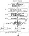
- FIG. 4is a flowchart illustrating an exemplary operation of the machine learning device illustrated as FIG. 1 .
- a learning operationlearning processing
- three-dimensional measurementis performed by the three-dimensional measuring device 15 and the measurement result is output (step S 11 in FIG. 4 ).
- step S 11for example, a three-dimensional map (data output from the three-dimensional measuring device 15 ) for each workpiece 12 placed in a random fashion, including a bulk-loaded state, is obtained and output to the state variable observation unit 21 , and the coordinate computation unit 19 receives the three-dimensional map for each workpiece 12 , and computes and outputs a three-dimensional position (x, y, z) for each workpiece 12 to the state variable observation unit 21 , the operation result obtaining unit 26 , and the controller 16 .
- the coordinate computation unit 19may compute and output an orientation (w, p, r) for each workpiece 12 , based on the output of the three-dimensional measuring device 15 .
- the output (three-dimensional map) of the three-dimensional measuring device 15may be input to the state variable observation unit 21 via a preprocessing unit 50 which processes the output (the three-dimensional map) before inputting it to the state variable observation unit 21 , as will be described later with reference to FIG. 5 .
- Only the output of the three-dimensional measuring device 15may be input to the state variable observation unit 21 and may even be input to the state variable observation unit 21 via the preprocessing unit 50 , as will be described later with reference to FIG. 7 .
- execution and output of three-dimensional measurement in step S 11may include various forms.
- the state variable observation unit 21observes a three-dimensional map for each workpiece 12 from the three-dimensional measuring device 15 , and a state variable (data output from the three-dimensional measuring device 15 ), such as the three-dimensional position (x, y, z) and orientation (w, p, r), for each workpiece 12 from the coordinate computation unit 19 .
- the operation result obtaining unit 26obtains a result of a picking operation of the robot 14 for picking up the workpiece 12 by the hand unit 13 , based on the data output from the three-dimensional measuring device 15 (the data output from the coordinate computation unit 19 ).
- the operation result obtaining unit 26can obtain not only the data from the three-dimensional measuring device but also the result of the picking operation, such as the achievement level in transferring the picked workpiece 12 to a post-process and breakage of the picked workpiece 12 .
- the machine learning device 20decides an optimal operation, based on the data output from the three-dimensional measuring device 15 (step S 12 in FIG. 4 ), and the controller 16 outputs command data (manipulated variables) for the hand unit 13 (robot 14 ) and performs a picking operation of the workpiece 12 (step S 13 in FIG. 4 ).
- the workpiece picking resultis obtained by the above-mentioned operation result obtaining unit 26 (step S 14 in FIG. 4 ).
- step S 15 in FIG. 4It is then determined based on the output from the operation result obtaining unit 26 whether picking of the workpiece 12 has resulted in success or failure (step S 15 in FIG. 4 ).
- a positive rewardis set (step S 16 in FIG. 4 ).
- a negative rewardis set (step S 17 in FIG. 4 ).
- the action value table (value function)is then updated (step S 18 in FIG. 4 ).
- Determination as to whether picking of the workpiece 12 has resulted in success or failureis not limited to evaluation as to whether picking of the workpiece 12 has resulted in success or failure, and may include evaluation of, e.g., the achievement level in transferring the picked workpiece 12 to a post-process, the occurrence or non-occurrence of a change in state, such as breakage, of the picked workpiece 12 , or the time (cycle time) or energy (amount of power) taken for the hand unit 13 to grip and transport the workpiece 12 .
- a reward valueis computed by the reward computation unit 23 based on determination as to whether picking of the workpiece 12 has resulted in success or failure, and the action value table is updated by the value function update unit 24 .
- the learning unit 22sets a positive reward in the above-mentioned update expression of a value Q(s, a) (step S 16 ); otherwise, the learning unit 22 sets a negative reward in the above-mentioned update expression (step S 17 ).
- the learning unit 22updates the above-mentioned action value table every time the workpiece 12 is picked up (step S 18 ).
- the learning unit 22continues (learns) to update the action value table by repeating above-mentioned steps S 11 through S 18 .
- data input to the state variable observation unit 21is not limited to data output from the three-dimensional measuring device 15 , but may include data such as the output of other sensors, and part of command data from the controller 16 may even be used.
- the controller 16causes the robot 14 to perform a picking operation of the workpiece 12 , using command data (manipulated variables) output from the machine learning device 20 .
- Learning by the machine learning device 20is not limited to the picking operation of the workpiece 12 , and measurement parameters of the three-dimensional measuring device 15 , for example, may be learned, as described earlier.
- the robot system 10 including the machine learning device 20 in this embodimentcan learn an operation of the robot 14 for picking up any of a plurality of workpieces 12 placed in a random fashion, including a bulk-loaded state, by the hand unit 13 .
- the robot system 10can learn selection of an optimal operation of the robot 14 , for picking the workpieces 12 loaded in bulk, without human intervention.
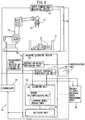
- FIG. 5is a block diagram illustrating the conceptual configuration of a robot system in another embodiment of the present invention, and represents a robot system that uses supervised learning.
- a robot system 10 ′ that uses supervised learning illustrated as FIG. 5is provided by adding a result (label)-bearing data recording unit 40 to the robot system 10 that uses Q-learning (reinforcement learning) illustrated as FIG. 1 .
- the robot system 10 ′ illustrated as FIG. 5further includes a preprocessing unit 50 which preprocesses data output from a three-dimensional measuring device 15 .
- the preprocessing unit 50may be provided to, e.g., the robot system 10 illustrated as FIG. 1 , as a matter of course.
- a machine learning device 30 in the robot system 10 ′ that uses supervised learningincludes a state variable observation unit 31 , an operation result obtaining unit 36 , a learning unit 32 , and a decision unit 35 , as depicted as FIG. 5 .
- the learning unit 32includes an error computation unit 33 and a learning model update unit 34 .
- the machine learning device 30learns and outputs manipulated variables such as command data for commanding a robot 14 to perform a picking operation of a workpiece 12 or measurement parameters of the three-dimensional measuring device 15 .
- the error computation unit 33 and the learning model update unit 34correspond to the reward computation unit 23 and the value function update unit 24 , respectively, in the robot system 10 that uses Q-learning illustrated as FIG. 1 .
- Other configurationssuch as those of the three-dimensional measuring device 15 , a controller 16 , and the robot 14 are the same as in FIG. 1 described earlier, and a description thereof will not be given.
- the error computation unit 33computes the error between the result (label) output from the operation result obtaining unit 36 and the output of a learning model mounted in the learning unit.
- the result (label)-bearing data recording unit 40can, for example, hold result (label)-bearing data obtained by the day before a predetermined day on which the robot 14 performs a task when the shapes of the workpieces 12 and the processes by the robot 14 remain unchanged, and provide the result (label)-bearing data held in the result (label)-bearing data recording unit 40 to the error computation unit 33 on the predetermined day.
- data obtained through, e.g., simulation performed outside the robot system 10 ′ or result (label)-bearing data obtained by another robot systemmay be provided to the error computation unit 33 of the robot system 10 ′ via a memory card or a communication line.
- the result (label)-bearing data recording unit 40may even be implemented in a non-volatile memory such as a flash memory and built into the learning unit 32 so that the result (label)-bearing data held in the result (label)-bearing data recording unit 40 can be directly used in the learning unit 32 .
- FIG. 6illustrates views for explaining exemplary processing of a preprocessing unit in the robot system illustrated as FIG. 5 .
- FIG. 6illustrates in (a), an example of data of the three-dimensional positions (orientations) of a plurality of workpieces 12 packed in bulk in a box 11 , i.e., data output from the three-dimensional measuring device 15 , and in (b) to (d), exemplary image data after preprocessing of workpieces 121 to 123 illustrated in (a) of FIG. 6 .
- Cylindrical metal partsare assumed as the workpieces 12 ( 121 to 123 ), and a suction pad which, for example, draws the longitudinal central portions of the cylindrical workpieces 12 using a negative pressure, instead of gripping them with two gripper portions, is assumed as the hand ( 13 ).
- the workpieces 12can be picked up by moving the suction pad ( 13 ) to these positions and drawing the workpieces 12 by suction.
- Numerical values used in (a) to (d) of FIG. 6represent the X-, Y-, and Z-directions in units of [mm].
- the Z-directioncorresponds to the direction of height (depth) of image data obtained by capturing the box 11 , accommodating a plurality of workpieces 12 loaded in bulk, using the three-dimensional measuring device 15 (e.g., including two cameras) located above the box 11 .
- the workpieces 12 of intereste.g., the three workpieces 121 to 123
- the workpieces 12 of interestare rotated and processed to adjust their center heights to “0,” based on data (three-dimensional image) output from the three-dimensional measuring device 15 .
- data output from the three-dimensional measuring device 15includes, e.g., information indicating the three-dimensional position (x, y, z) and orientation (w, p, r) of the longitudinal central portion of each workpiece 12 .
- the three workpieces 121 , 122 , and 123 of interestare rotated by ⁇ r and subtracted by z to uniform all their conditions, as illustrated as (b), (c), and (d) of FIG. 6 .
- the load of the machine learning device 30can be reduced by such preprocessing.
- the three-dimensional image depicted as (a) of FIG. 6is not data itself output from the three-dimensional measuring device 15 but, e.g., that obtained by lowering the threshold for selection from an image obtained by a program defining the order of picking of the workpieces 12 , implemented conventionally.
- This processingitself may even be performed by the preprocessing unit 50 .
- Such processing by the preprocessing unit 50may diversely vary depending on a variety of conditions, including, e.g., the shapes of the workpieces 12 and the type of hand 13 , as a matter of course.
- the preprocessing unit 50inputs to the state variable observation unit 31 , data (a three-dimensional map for each workpiece 12 ) output from the three-dimensional measuring device 15 processed before being input to the state variable observation unit 31 .
- the error computation unit 33that receives a result (label) output from the operation result obtaining unit 36 determines that an error ⁇ log(y) exists when the actual picking operation of the workpiece 12 has resulted in success and that an error ⁇ log(1 ⁇ y) exists when this operation has resulted in failure, and performs processing aiming at minimizing the error.
- image data of the workpieces 121 to 123 of interest after preprocessingas depicted as (b) to (d) of FIG. 6 , and data of the three-dimensional position and orientation (x, y, z, w, p, r) for each of the workpieces 121 to 123 are provided.
- FIG. 7is a block diagram illustrating a modification of the robot system illustrated as FIG. 1 .
- the coordinate computation unit 19is omitted, and the state variable observation unit 21 observes the state variable of the robot 14 upon receiving only a three-dimensional map from the three-dimensional measuring device 15 .
- the controller 16may naturally be equipped with a configuration equivalent to the coordinate computation unit 19 .
- the configuration illustrated as FIG. 7is also applicable to, e.g., the robot system 10 ′ that uses supervised learning described earlier with reference to FIG. 5 . In other words, in the robot system 10 ′ illustrated as FIG.
- the preprocessing unit 50can be omitted, and the state variable observation unit 31 can observe the state variable of the robot 14 upon receiving only a three-dimensional map from the three-dimensional measuring device 15 .
- machine learning deviceAs described in detail above, according to this embodiment, it is possible to provide a machine learning device, a robot system, and a machine learning method which can learn an optimal operation of a robot in picking up workpieces placed in a random fashion, including a bulk-loaded state, without human intervention.
- the machine learning devices 20 and 30 in the present inventionare not limited to those that use reinforcement learning (e.g., Q-learning) or supervised learning, and various machine learning algorithms are applicable.
- the machine learning device, the robot system, and the machine learning method according to the present inventionhave an advantageous effect of learning an optimal operation of a robot in picking up workpieces placed in a random fashion, including a bulk-loaded state, without human intervention.
Landscapes
- Engineering & Computer Science (AREA)
- Robotics (AREA)
- Mechanical Engineering (AREA)
- Health & Medical Sciences (AREA)
- General Health & Medical Sciences (AREA)
- Orthopedic Medicine & Surgery (AREA)
- Manipulator (AREA)
Abstract
Description
- The robot observes the environmental state to decide its action;
- The environment may change according to a certain rule and a human may change the environment by his or her own action;
- A reward signal is returned every time action is taken;
- The sum of (discount) rewards in the future is to be maximized;
- Learning starts in a state in which a result to be brought about by the action is totally unknown or known only incompletely. In other words, the robot can obtain the result of an action as data only after it actually takes action. This means that an optimal action may be preferably searched for by trial and error; and
- Learning can be started at a good starting point by starting from the state in which learning has been performed in advance to imitate human behaviors (a technique such as the above-mentioned supervised learning or reverse reinforcement learning).
where stis the environmental state at time t and atis the action at time t. Upon the action at, the state changes to st+1. rt+1is the reward received upon a change in state. The term attached with max is the product of the Q-value multiplied by γ when an action a having the highest Q-value known in the state st+1is selected. γ is a parameter called the discount rate, satisfying 0<γ<1. α is a learning factor satisfying 0<α≤1.
y=fk(Σi=1nxiwi−θ) (2)
where θ is the bias and fkis the activation function. Note that all of the input x, the result y, and the weight w are vectors.
Claims (21)
Priority Applications (2)
| Application Number | Priority Date | Filing Date | Title |
|---|---|---|---|
| US16/860,071US11780095B2 (en) | 2015-07-31 | 2020-04-28 | Machine learning device, robot system, and machine learning method for learning object picking operation |
| US18/209,477US20230321837A1 (en) | 2015-07-31 | 2023-06-14 | Machine learning device, robot system, and machine learning method for learning object picking operation |
Applications Claiming Priority (4)
| Application Number | Priority Date | Filing Date | Title |
|---|---|---|---|
| JP2015-152067 | 2015-07-31 | ||
| JP2015152067 | 2015-07-31 | ||
| JP2015233857AJP6522488B2 (en) | 2015-07-31 | 2015-11-30 | Machine learning apparatus, robot system and machine learning method for learning work taking-out operation |
| JP2015-233857 | 2015-11-30 |
Related Child Applications (1)
| Application Number | Title | Priority Date | Filing Date |
|---|---|---|---|
| US16/860,071ContinuationUS11780095B2 (en) | 2015-07-31 | 2020-04-28 | Machine learning device, robot system, and machine learning method for learning object picking operation |
Publications (2)
| Publication Number | Publication Date |
|---|---|
| US20170028562A1 US20170028562A1 (en) | 2017-02-02 |
| US10717196B2true US10717196B2 (en) | 2020-07-21 |
Family
ID=57795973
Family Applications (3)
| Application Number | Title | Priority Date | Filing Date |
|---|---|---|---|
| US15/223,141ActiveUS10717196B2 (en) | 2015-07-31 | 2016-07-29 | Machine learning device, robot system, and machine learning method for learning workpiece picking operation |
| US16/860,071ActiveUS11780095B2 (en) | 2015-07-31 | 2020-04-28 | Machine learning device, robot system, and machine learning method for learning object picking operation |
| US18/209,477PendingUS20230321837A1 (en) | 2015-07-31 | 2023-06-14 | Machine learning device, robot system, and machine learning method for learning object picking operation |
Family Applications After (2)
| Application Number | Title | Priority Date | Filing Date |
|---|---|---|---|
| US16/860,071ActiveUS11780095B2 (en) | 2015-07-31 | 2020-04-28 | Machine learning device, robot system, and machine learning method for learning object picking operation |
| US18/209,477PendingUS20230321837A1 (en) | 2015-07-31 | 2023-06-14 | Machine learning device, robot system, and machine learning method for learning object picking operation |
Country Status (2)
| Country | Link |
|---|---|
| US (3) | US10717196B2 (en) |
| DE (2) | DE102016009030B4 (en) |
Cited By (9)
| Publication number | Priority date | Publication date | Assignee | Title |
|---|---|---|---|---|
| US10930037B2 (en)* | 2016-02-25 | 2021-02-23 | Fanuc Corporation | Image processing device for displaying object detected from input picture image |
| US20210122053A1 (en)* | 2019-10-25 | 2021-04-29 | Kindred Systems Inc. | Systems and methods for active perception and coordination between robotic vision systems and manipulators |
| US11034018B2 (en)* | 2017-05-31 | 2021-06-15 | Preferred Networks, Inc. | Learning device, learning method, learning model, detection device and grasping system |
| US20210229275A1 (en)* | 2018-06-14 | 2021-07-29 | Yamaha Hatsudoki Kabushiki Kaisha | Machine learning device and robot system provided with same |
| US11185979B2 (en)* | 2016-11-22 | 2021-11-30 | Panasonic Intellectual Property Management Co., Ltd. | Picking system and method for controlling same |
| US11780095B2 (en)* | 2015-07-31 | 2023-10-10 | Fanuc Corporation | Machine learning device, robot system, and machine learning method for learning object picking operation |
| US11904469B2 (en) | 2015-07-31 | 2024-02-20 | Fanuc Corporation | Machine learning device, robot controller, robot system, and machine learning method for learning action pattern of human |
| US12162150B2 (en) | 2018-07-04 | 2024-12-10 | Preferred Networks, Inc. | Learning method, learning apparatus, and learning system |
| US12290917B2 (en) | 2021-05-14 | 2025-05-06 | Industrial Technology Research Institute | Object pose estimation system, execution method thereof and graphic user interface |
Families Citing this family (96)
| Publication number | Priority date | Publication date | Assignee | Title |
|---|---|---|---|---|
| US20140005640A1 (en) | 2012-06-28 | 2014-01-02 | Ethicon Endo-Surgery, Inc. | Surgical end effector jaw and electrode configurations |
| DE102016120775B4 (en) | 2015-11-02 | 2025-02-20 | Cognex Corporation | System and method for detecting lines in an image with a vision system |
| US10937168B2 (en) | 2015-11-02 | 2021-03-02 | Cognex Corporation | System and method for finding and classifying lines in an image with a vision system |
| EP3485370A4 (en) | 2016-07-18 | 2020-03-25 | Lael Odhner | Assessing robotic grasping |
| JP6706173B2 (en)* | 2016-08-09 | 2020-06-03 | 株式会社日立製作所 | Control device, control method, and control program |
| US10416629B1 (en)* | 2016-11-21 | 2019-09-17 | X Development Llc | Acoustic contact sensors |
| US10846326B2 (en)* | 2016-11-30 | 2020-11-24 | Optim Corporation | System and method for controlling camera and program |
| JP2018126796A (en)* | 2017-02-06 | 2018-08-16 | セイコーエプソン株式会社 | Control device, robot, and robot system |
| JP2018126798A (en)* | 2017-02-06 | 2018-08-16 | セイコーエプソン株式会社 | Control device, robot, and robot system |
| JP2018126797A (en)* | 2017-02-06 | 2018-08-16 | セイコーエプソン株式会社 | Control device, robot, and robot system |
| JP2018126799A (en)* | 2017-02-06 | 2018-08-16 | セイコーエプソン株式会社 | Control device, robot and robot system |
| JP6453922B2 (en)* | 2017-02-06 | 2019-01-16 | ファナック株式会社 | Work picking apparatus and work picking method for improving work picking operation |
| JP6490124B2 (en)* | 2017-03-07 | 2019-03-27 | ファナック株式会社 | Laser processing apparatus and machine learning apparatus |
| JP6542824B2 (en) | 2017-03-13 | 2019-07-10 | ファナック株式会社 | Image processing apparatus and image processing method for calculating likelihood of image of object detected from input image |
| JP6603257B2 (en)* | 2017-03-31 | 2019-11-06 | ファナック株式会社 | Behavior information learning device, management device, robot control system, and behavior information learning method |
| JP6490132B2 (en) | 2017-03-31 | 2019-03-27 | ファナック株式会社 | Robot control device, machine learning device, and machine learning method |
| WO2018185857A1 (en) | 2017-04-04 | 2018-10-11 | 株式会社Mujin | Information processing device, picking system, logistics system, program, and information processing method |
| DE112017007397B4 (en)* | 2017-04-04 | 2021-09-30 | Mujin, Inc. | Control device, gripping system, distribution system, program, control method and manufacturing method |
| WO2018185861A1 (en)* | 2017-04-04 | 2018-10-11 | 株式会社Mujin | Control device, picking system, distribution system, program, and control method |
| CN110494258B (en)* | 2017-04-04 | 2022-08-09 | 牧今科技 | Control device, pickup system, logistics system, program, control method, and production method |
| JP6258557B1 (en)* | 2017-04-04 | 2018-01-10 | 株式会社Mujin | Control device, picking system, distribution system, program, control method, and production method |
| JP6514260B2 (en) | 2017-04-13 | 2019-05-15 | ファナック株式会社 | Control device and machine learning device |
| JP6526100B2 (en)* | 2017-04-28 | 2019-06-05 | ファナック株式会社 | Material pick-up system |
| JP6542839B2 (en)* | 2017-06-07 | 2019-07-10 | ファナック株式会社 | Control device and machine learning device |
| JP6886869B2 (en)* | 2017-06-09 | 2021-06-16 | 川崎重工業株式会社 | Motion prediction system and motion prediction method |
| JP6577527B2 (en) | 2017-06-15 | 2019-09-18 | ファナック株式会社 | Learning device, control device and control system |
| JP6564426B2 (en)* | 2017-07-07 | 2019-08-21 | ファナック株式会社 | Parts supply device and machine learning device |
| WO2019028075A1 (en)* | 2017-08-01 | 2019-02-07 | Enova Technology, Inc. | Intelligent robots |
| JP6691077B2 (en) | 2017-08-18 | 2020-04-28 | ファナック株式会社 | Control device and machine learning device |
| JP6680732B2 (en) | 2017-08-23 | 2020-04-15 | ファナック株式会社 | Goods stacking device and machine learning device |
| CA3073516A1 (en)* | 2017-09-01 | 2019-03-07 | The Regents Of The University Of California | Robotic systems and methods for robustly grasping and targeting objects |
| EP3456485B1 (en)* | 2017-09-15 | 2021-02-17 | Siemens Aktiengesellschaft | Optimisation of an automated process for selecting and gripping an object by a robot |
| JP6695843B2 (en) | 2017-09-25 | 2020-05-20 | ファナック株式会社 | Device and robot system |
| JP6626057B2 (en)* | 2017-09-27 | 2019-12-25 | ファナック株式会社 | Inspection device and inspection system |
| JP6579498B2 (en)* | 2017-10-20 | 2019-09-25 | 株式会社安川電機 | Automation device and position detection device |
| DE102017010678B4 (en)* | 2017-11-17 | 2021-07-01 | Kuka Deutschland Gmbh | Method and system for specifying an application pattern command lexicon for inputting at least one robot command |
| DE102017010676A1 (en)* | 2017-11-17 | 2019-05-23 | Kuka Deutschland Gmbh | Quality assurance of a process |
| JP6676030B2 (en) | 2017-11-20 | 2020-04-08 | 株式会社安川電機 | Grasping system, learning device, gripping method, and model manufacturing method |
| JP6680750B2 (en)* | 2017-11-22 | 2020-04-15 | ファナック株式会社 | Control device and machine learning device |
| US10828778B2 (en)* | 2017-11-30 | 2020-11-10 | Abb Schweiz Ag | Method for operating a robot |
| JP6892400B2 (en)* | 2018-01-30 | 2021-06-23 | ファナック株式会社 | Machine learning device that learns the failure occurrence mechanism of laser devices |
| JP6703020B2 (en) | 2018-02-09 | 2020-06-03 | ファナック株式会社 | Control device and machine learning device |
| JP6874712B2 (en)* | 2018-02-19 | 2021-05-19 | オムロン株式会社 | Simulation equipment, simulation method and simulation program |
| JP6879238B2 (en)* | 2018-03-13 | 2021-06-02 | オムロン株式会社 | Work picking device and work picking method |
| US20190291270A1 (en)* | 2018-03-20 | 2019-09-26 | Fanuc Corporation | Controller, machine learning device, and system |
| SE544090C2 (en) | 2018-04-22 | 2021-12-21 | Zenrobotics Oy | Waste Sorting Gantry Robot |
| SE543130C2 (en) | 2018-04-22 | 2020-10-13 | Zenrobotics Oy | A waste sorting robot gripper |
| US11014231B2 (en)* | 2018-05-03 | 2021-05-25 | Fujitsu Limited | Robotic device task learning |
| SE544741C2 (en) | 2018-05-11 | 2022-11-01 | Genie Ind Bv | Waste Sorting Gantry Robot and associated method |
| US11858140B2 (en)* | 2018-05-25 | 2024-01-02 | Kawasaki Jukogyo Kabushiki Kaisha | Robot system and supplemental learning method |
| DE112018007727B4 (en)* | 2018-06-14 | 2022-10-06 | Yamaha Hatsudoki Kabushiki Kaisha | robotic system |
| JP7102241B2 (en)* | 2018-06-14 | 2022-07-19 | ヤマハ発動機株式会社 | Machine learning device and robot system equipped with it |
| DE102018211044A1 (en)* | 2018-07-04 | 2020-01-09 | Kuka Deutschland Gmbh | Method and system for analyzing and / or configuring an industrial plant |
| JP6505341B1 (en)* | 2018-07-06 | 2019-04-24 | 三菱電機株式会社 | Machine learning apparatus, numerical control apparatus, machine tool and machine learning method |
| JP7031540B2 (en) | 2018-09-07 | 2022-03-08 | オムロン株式会社 | Object recognition devices, manipulators, and mobile robots |
| JP6904327B2 (en)* | 2018-11-30 | 2021-07-14 | オムロン株式会社 | Control device, control method, and control program |
| JP7128736B2 (en) | 2018-12-27 | 2022-08-31 | 川崎重工業株式会社 | ROBOT CONTROL DEVICE, ROBOT SYSTEM AND ROBOT CONTROL METHOD |
| JP7000359B2 (en) | 2019-01-16 | 2022-01-19 | ファナック株式会社 | Judgment device |
| JP2020166371A (en)* | 2019-03-28 | 2020-10-08 | セイコーエプソン株式会社 | Information processing method, information processing device, object detection device and robot system |
| US11185980B2 (en)* | 2019-04-16 | 2021-11-30 | Abb Schweiz Ag | Machine learning-based systems and methods for controlling robotic object picking and placement in training and run time environments |
| US11547468B2 (en) | 2019-06-27 | 2023-01-10 | Cilag Gmbh International | Robotic surgical system with safety and cooperative sensing control |
| US11413102B2 (en) | 2019-06-27 | 2022-08-16 | Cilag Gmbh International | Multi-access port for surgical robotic systems |
| US11376082B2 (en) | 2019-06-27 | 2022-07-05 | Cilag Gmbh International | Robotic surgical system with local sensing of functional parameters based on measurements of multiple physical inputs |
| US11399906B2 (en) | 2019-06-27 | 2022-08-02 | Cilag Gmbh International | Robotic surgical system for controlling close operation of end-effectors |
| US11723729B2 (en) | 2019-06-27 | 2023-08-15 | Cilag Gmbh International | Robotic surgical assembly coupling safety mechanisms |
| US11607278B2 (en) | 2019-06-27 | 2023-03-21 | Cilag Gmbh International | Cooperative robotic surgical systems |
| US11612445B2 (en) | 2019-06-27 | 2023-03-28 | Cilag Gmbh International | Cooperative operation of robotic arms |
| US11648674B2 (en)* | 2019-07-23 | 2023-05-16 | Teradyne, Inc. | System and method for robotic bin picking using advanced scanning techniques |
| JP7415356B2 (en)* | 2019-07-29 | 2024-01-17 | セイコーエプソン株式会社 | Program transfer system and robot system |
| DE102019121889B3 (en)* | 2019-08-14 | 2020-11-19 | Robominds GmbH | Automation system and process for handling products |
| JP7295421B2 (en)* | 2019-08-22 | 2023-06-21 | オムロン株式会社 | Control device and control method |
| GB2600843B (en) | 2019-08-28 | 2022-11-09 | Daily Color Inc | Robot control device |
| JP7021158B2 (en)* | 2019-09-04 | 2022-02-16 | 株式会社東芝 | Robot system and drive method |
| CN110497415B (en)* | 2019-09-05 | 2021-05-28 | 首都师范大学 | A Consistent Control Method for Multi-Manipulator System Based on Disturbance Observer |
| US12399567B2 (en) | 2019-09-20 | 2025-08-26 | Nvidia Corporation | Vision-based teleoperation of dexterous robotic system |
| JP7458741B2 (en)* | 2019-10-21 | 2024-04-01 | キヤノン株式会社 | Robot control device and its control method and program |
| DE102020127508B4 (en) | 2019-10-24 | 2022-09-08 | Nvidia Corporation | Pose tracking of objects in hand |
| US12109686B2 (en) | 2020-01-16 | 2024-10-08 | Omron Corporation | Control apparatus, control method, and computer-readable storage medium storing a control program |
| EP4114622A1 (en)* | 2020-03-06 | 2023-01-11 | Embodied Intelligence Inc. | Imaging process for detecting failure modes |
| DE102020113277B4 (en) | 2020-05-15 | 2024-07-11 | Gerhard Schubert Gesellschaft mit beschränkter Haftung | Method for generating a training data set for training an industrial robot, method for controlling the operation of an industrial robot and industrial robot |
| DE102020113278B4 (en) | 2020-05-15 | 2024-07-25 | Gerhard Schubert Gesellschaft mit beschränkter Haftung | Method for controlling the operation of an industrial robot, industrial robot and arrangement for moving objects |
| SE544165C2 (en) | 2020-06-24 | 2022-02-15 | Zenrobotics Oy | Waste Sorting Robot |
| DE102020212658A1 (en) | 2020-10-07 | 2022-04-07 | Robert Bosch Gesellschaft mit beschränkter Haftung | Apparatus and method for controlling a robotic device |
| SE544103C2 (en) | 2020-10-28 | 2021-12-21 | Zenrobotics Oy | Waste Sorting Robot with gripper that releases waste object at a throw position |
| WO2022091269A1 (en) | 2020-10-28 | 2022-05-05 | ヤマハ発動機株式会社 | Device for seeking workpiece holding form for robot hand and method therefor |
| JP7492440B2 (en)* | 2020-11-10 | 2024-05-29 | 株式会社日立製作所 | ROBOT CONTROL SYSTEM, ROBOT CONTROL METHOD, AND PROGRAM |
| KR20230119159A (en)* | 2020-12-02 | 2023-08-16 | 오카도 이노베이션 리미티드 | Pixel-by-pixel prediction for phage generation |
| US20240001544A1 (en)* | 2020-12-08 | 2024-01-04 | Sony Group Corporation | Learning device, learning system, and learning method |
| US11814248B2 (en) | 2021-02-23 | 2023-11-14 | Intelligrated Headquarters, Llc | Methods, apparatuses, and systems for automatically detecting objects within a conveyor zone |
| JP7662938B2 (en)* | 2021-04-06 | 2025-04-16 | 株式会社デンソーウェーブ | Machine learning device, machine learning method, and robot control device |
| CN117377559A (en)* | 2021-05-25 | 2024-01-09 | 西门子股份公司 | Automatic generation of path constraints for grasp stability |
| US12358136B2 (en) | 2021-06-30 | 2025-07-15 | Cilag Gmbh International | Grasping work determination and indications thereof |
| US11931026B2 (en) | 2021-06-30 | 2024-03-19 | Cilag Gmbh International | Staple cartridge replacement |
| US11974829B2 (en) | 2021-06-30 | 2024-05-07 | Cilag Gmbh International | Link-driven articulation device for a surgical device |
| CN114125416B (en)* | 2021-10-13 | 2024-03-19 | 厦门微图软件科技有限公司 | Three-dimensional detection platform software and device based on machine learning and deep learning |
| CN116312147B (en)* | 2023-05-11 | 2023-07-21 | 深圳市亚博智能科技有限公司 | Programming teaching method and system based on teaching robot |
Citations (32)
| Publication number | Priority date | Publication date | Assignee | Title |
|---|---|---|---|---|
| US5172253A (en) | 1990-06-21 | 1992-12-15 | Inernational Business Machines Corporation | Neural network model for reaching a goal state |
| JPH0588721A (en) | 1991-09-30 | 1993-04-09 | Fujitsu Ltd | Articulated robot controller |
| JPH06203166A (en) | 1993-01-06 | 1994-07-22 | Fujitsu Ltd | Multi-dimensional position measurement, control device, and learning method |
| JPH11175132A (en) | 1997-12-15 | 1999-07-02 | Omron Corp | Robot, robot system, learning method for robot, learning method for robot system, and recording medium |
| JPH11272845A (en) | 1998-03-23 | 1999-10-08 | Denso Corp | Image recognition device |
| JP2000094374A (en) | 1998-09-25 | 2000-04-04 | Matsushita Electric Works Ltd | Picking device |
| US6394731B1 (en) | 1998-09-17 | 2002-05-28 | Toyota Jidosha Kabushiki Kaisha | Work assist device |
| US20020158599A1 (en) | 2000-03-31 | 2002-10-31 | Masahiro Fujita | Robot device, robot device action control method, external force detecting device and external force detecting method |
| US20050071048A1 (en)* | 2003-09-29 | 2005-03-31 | Fanuc Ltd. | Robot system |
| JP2005199383A (en) | 2004-01-15 | 2005-07-28 | Sony Corp | Dynamic control device and biped walking mobile body using dynamic control device |
| JP2006320997A (en) | 2005-05-18 | 2006-11-30 | Nippon Telegr & Teleph Corp <Ntt> | Robot action selection device and robot action selection method |
| CN101051215A (en) | 2006-04-06 | 2007-10-10 | 索尼株式会社 | Learning apparatus, learning method, and program |
| US20070274812A1 (en) | 2006-05-29 | 2007-11-29 | Fanuc Ltd | Workpiece picking device and method |
| US20070282485A1 (en)* | 2006-06-06 | 2007-12-06 | Fanuc Ltd | Robot simulation apparatus |
| US20090105881A1 (en) | 2002-07-25 | 2009-04-23 | Intouch Technologies, Inc. | Medical Tele-Robotic System |
| JP2009262279A (en) | 2008-04-25 | 2009-11-12 | Nec Corp | Robot, robot program sharing system, robot program sharing method, and program |
| US20100087955A1 (en) | 2007-06-27 | 2010-04-08 | Yuko Tsusaka | Apparatus and method for controlling robot arm, and robot and program |
| US20100092032A1 (en)* | 2008-10-10 | 2010-04-15 | Remus Boca | Methods and apparatus to facilitate operations in image based systems |
| US20100114807A1 (en) | 2008-11-04 | 2010-05-06 | Honda Motor Co., Ltd. | Reinforcement learning system |
| US20100262286A1 (en) | 2009-04-03 | 2010-10-14 | Robert Eidenberger | Decision making mechanism, method, module, and robot configured to decide on at least one prospective action of the robot |
| US20110015785A1 (en) | 2009-01-09 | 2011-01-20 | Yuko Tsusaka | Control apparatus and control method for robot arm, robot, control program for robot arm, and integrated electronic circuit |
| US20120158180A1 (en) | 2010-12-15 | 2012-06-21 | Canon Kabushiki Kaisha | Object gripping apparatus, method of controlling the same and storage medium |
| US20120253514A1 (en) | 2011-03-30 | 2012-10-04 | Norikazu Sugimoto | Reinforcement learning apparatus, control apparatus, and reinforcement learning method |
| JP2013052490A (en) | 2011-09-06 | 2013-03-21 | Mitsubishi Electric Corp | Workpiece takeout device |
| US20130345873A1 (en) | 2012-06-21 | 2013-12-26 | Rethink Robotics, Inc. | Training and operating industrial robots |
| US20140031985A1 (en) | 2012-07-26 | 2014-01-30 | Fanuc Corporation | Apparatus and method of taking out bulk stored articles by robot |
| US20140067127A1 (en) | 2012-08-29 | 2014-03-06 | Fanuc Corporation | Apparatus and method of taking out bulk stored articles by robot |
| US20140114888A1 (en) | 2012-10-18 | 2014-04-24 | Sony Corporation | Information processing apparatus, information processing method, and program |
| CN103753557A (en) | 2014-02-14 | 2014-04-30 | 上海创绘机器人科技有限公司 | Self-balance control method of movable type inverted pendulum system and self-balance vehicle intelligent control system |
| JP2014206795A (en) | 2013-04-11 | 2014-10-30 | 日本電信電話株式会社 | Reinforcement learning method, apparatus and program based on linear model |
| US20150039129A1 (en) | 2013-07-31 | 2015-02-05 | Kabushiki Kaisha Yaskawa Denki | Robot system and product manufacturing method |
| US20150100530A1 (en) | 2013-10-08 | 2015-04-09 | Google Inc. | Methods and apparatus for reinforcement learning |
Family Cites Families (32)
| Publication number | Priority date | Publication date | Assignee | Title |
|---|---|---|---|---|
| US3940110A (en) | 1974-04-12 | 1976-02-24 | Kenro Motoda | Lifting apparatus |
| US5243702A (en)* | 1990-10-05 | 1993-09-07 | Bull Hn Information Systems Inc. | Minimum contention processor and system bus system |
| US5333210A (en)* | 1992-07-02 | 1994-07-26 | The United States Of America As Represented By The Administrator Of The National Aeronautics And Space Administration | Method and system for pattern analysis using a coarse-coded neural network |
| JPH06106490A (en) | 1992-09-29 | 1994-04-19 | Fujitsu Ltd | Control device |
| US5865426A (en) | 1996-03-27 | 1999-02-02 | Kazerooni; Homayoon | Human power amplifier for vertical maneuvers |
| US6216056B1 (en) | 1996-12-16 | 2001-04-10 | Kabushiki Kaisha Sanyo Seiki Seisakusho | Method of controlling force assisting device and control apparatus using the same |
| US6353814B1 (en) | 1997-10-08 | 2002-03-05 | Michigan State University | Developmental learning machine and method |
| US6272396B1 (en) | 1998-02-20 | 2001-08-07 | Tairob Industrial Technology Ltd. | Method for applying knowledge from a skilled worker via a master expert machine to a slave expert machine for repetitive tasks |
| WO2004103651A1 (en) | 1999-06-01 | 2004-12-02 | Hirohiko Arai | Control method for cooperative object-carrying robot and device therefor |
| US6204619B1 (en) | 1999-10-04 | 2001-03-20 | Daimlerchrysler Corporation | Dynamic control algorithm and program for power-assisted lift device |
| JP3188953B2 (en) | 1999-10-13 | 2001-07-16 | 経済産業省産業技術総合研究所長 | Power assist device and control method thereof |
| EP1484716A1 (en) | 2003-06-06 | 2004-12-08 | Sony France S.A. | An architecture for self-developing devices |
| JP2005118959A (en) | 2003-10-17 | 2005-05-12 | Toyoda Mach Works Ltd | Work support device, work support method, positioning work support device and power assist work support device |
| US20060293617A1 (en) | 2004-02-05 | 2006-12-28 | Reability Inc. | Methods and apparatuses for rehabilitation and training |
| JP2005238422A (en) | 2004-02-27 | 2005-09-08 | Sony Corp | Robot device, its state transition model construction method and behavior control method |
| JP3930490B2 (en) | 2004-04-23 | 2007-06-13 | ファナック株式会社 | Article take-out device |
| JP5052013B2 (en) | 2005-03-17 | 2012-10-17 | ソニー株式会社 | Robot apparatus and control method thereof |
| JP4153528B2 (en)* | 2006-03-10 | 2008-09-24 | ファナック株式会社 | Apparatus, program, recording medium and method for robot simulation |
| JP4361132B2 (en) | 2007-07-05 | 2009-11-11 | パナソニック株式会社 | ROBOT ARM CONTROL DEVICE AND CONTROL METHOD, ROBOT, AND CONTROL PROGRAM |
| US7957583B2 (en)* | 2007-08-02 | 2011-06-07 | Roboticvisiontech Llc | System and method of three-dimensional pose estimation |
| JP5152780B2 (en) | 2007-09-06 | 2013-02-27 | 国立大学法人 筑波大学 | Function approximation device, reinforcement learning system, function approximation system, and function approximation program |
| JP4565023B2 (en)* | 2008-07-04 | 2010-10-20 | ファナック株式会社 | Article take-out device |
| JP2010086405A (en) | 2008-10-01 | 2010-04-15 | Fuji Heavy Ind Ltd | System for adapting control parameter |
| JP5528214B2 (en) | 2010-05-28 | 2014-06-25 | 本田技研工業株式会社 | Learning control system and learning control method |
| FI20105732A0 (en)* | 2010-06-24 | 2010-06-24 | Zenrobotics Oy | Procedure for selecting physical objects in a robotic system |
| JP2012135820A (en) | 2010-12-24 | 2012-07-19 | Ihi Corp | Automatic picking device and automatic picking method |
| US20150127154A1 (en) | 2011-06-02 | 2015-05-07 | Brain Corporation | Reduced degree of freedom robotic controller apparatus and methods |
| JP2013180369A (en) | 2012-03-01 | 2013-09-12 | Ihi Corp | Adaptive machine |
| US9308645B2 (en) | 2012-03-21 | 2016-04-12 | GM Global Technology Operations LLC | Method of inferring intentions of an operator to move a robotic system |
| JPWO2015037165A1 (en) | 2013-09-12 | 2017-03-02 | 日本電気株式会社 | Information processing apparatus, predictive control method, and program |
| JP5902664B2 (en) | 2013-12-25 | 2016-04-13 | ファナック株式会社 | Human cooperative industrial robot with protective member |
| DE102016009030B4 (en)* | 2015-07-31 | 2019-05-09 | Fanuc Corporation | Machine learning device, robot system and machine learning system for learning a workpiece receiving operation |
- 2016
- 2016-07-26DEDE102016009030.8Apatent/DE102016009030B4/enactiveActive
- 2016-07-26DEDE102016015936.7Apatent/DE102016015936B8/enactiveActive
- 2016-07-29USUS15/223,141patent/US10717196B2/enactiveActive
- 2020
- 2020-04-28USUS16/860,071patent/US11780095B2/enactiveActive
- 2023
- 2023-06-14USUS18/209,477patent/US20230321837A1/enactivePending
Patent Citations (44)
| Publication number | Priority date | Publication date | Assignee | Title |
|---|---|---|---|---|
| US5172253A (en) | 1990-06-21 | 1992-12-15 | Inernational Business Machines Corporation | Neural network model for reaching a goal state |
| JPH0588721A (en) | 1991-09-30 | 1993-04-09 | Fujitsu Ltd | Articulated robot controller |
| JPH06203166A (en) | 1993-01-06 | 1994-07-22 | Fujitsu Ltd | Multi-dimensional position measurement, control device, and learning method |
| JPH11175132A (en) | 1997-12-15 | 1999-07-02 | Omron Corp | Robot, robot system, learning method for robot, learning method for robot system, and recording medium |
| JPH11272845A (en) | 1998-03-23 | 1999-10-08 | Denso Corp | Image recognition device |
| US6394731B1 (en) | 1998-09-17 | 2002-05-28 | Toyota Jidosha Kabushiki Kaisha | Work assist device |
| JP2000094374A (en) | 1998-09-25 | 2000-04-04 | Matsushita Electric Works Ltd | Picking device |
| US20020158599A1 (en) | 2000-03-31 | 2002-10-31 | Masahiro Fujita | Robot device, robot device action control method, external force detecting device and external force detecting method |
| CN1380846A (en) | 2000-03-31 | 2002-11-20 | 索尼公司 | Robotic device, method for controlling motion of robotic device, and external force detection device and method |
| US20090105881A1 (en) | 2002-07-25 | 2009-04-23 | Intouch Technologies, Inc. | Medical Tele-Robotic System |
| JP2005103681A (en) | 2003-09-29 | 2005-04-21 | Fanuc Ltd | Robot system |
| US20050071048A1 (en)* | 2003-09-29 | 2005-03-31 | Fanuc Ltd. | Robot system |
| JP2005199383A (en) | 2004-01-15 | 2005-07-28 | Sony Corp | Dynamic control device and biped walking mobile body using dynamic control device |
| JP2006320997A (en) | 2005-05-18 | 2006-11-30 | Nippon Telegr & Teleph Corp <Ntt> | Robot action selection device and robot action selection method |
| CN101051215A (en) | 2006-04-06 | 2007-10-10 | 索尼株式会社 | Learning apparatus, learning method, and program |
| US20070239644A1 (en) | 2006-04-06 | 2007-10-11 | Katsuki Minamino | Learning apparatus, learning method, and program |
| US20070274812A1 (en) | 2006-05-29 | 2007-11-29 | Fanuc Ltd | Workpiece picking device and method |
| JP2007313624A (en) | 2006-05-29 | 2007-12-06 | Fanuc Ltd | Work picking apparatus and method |
| EP1862270B1 (en) | 2006-05-29 | 2012-04-25 | Fanuc Corporation | Workpiece picking device and method |
| US20070282485A1 (en)* | 2006-06-06 | 2007-12-06 | Fanuc Ltd | Robot simulation apparatus |
| JP2007326160A (en) | 2006-06-06 | 2007-12-20 | Fanuc Ltd | Robot simulation device |
| US20100087955A1 (en) | 2007-06-27 | 2010-04-08 | Yuko Tsusaka | Apparatus and method for controlling robot arm, and robot and program |
| JP2009262279A (en) | 2008-04-25 | 2009-11-12 | Nec Corp | Robot, robot program sharing system, robot program sharing method, and program |
| US20100092032A1 (en)* | 2008-10-10 | 2010-04-15 | Remus Boca | Methods and apparatus to facilitate operations in image based systems |
| JP2010134907A (en) | 2008-11-04 | 2010-06-17 | Honda Motor Co Ltd | Reinforcement learning system |
| US20100114807A1 (en) | 2008-11-04 | 2010-05-06 | Honda Motor Co., Ltd. | Reinforcement learning system |
| US20110015785A1 (en) | 2009-01-09 | 2011-01-20 | Yuko Tsusaka | Control apparatus and control method for robot arm, robot, control program for robot arm, and integrated electronic circuit |
| US20100262286A1 (en) | 2009-04-03 | 2010-10-14 | Robert Eidenberger | Decision making mechanism, method, module, and robot configured to decide on at least one prospective action of the robot |
| JP2010244549A (en) | 2009-04-03 | 2010-10-28 | Siemens Ag | A decision mechanism, method, module and robot configured to determine at least one future activity of the robot |
| US20120158180A1 (en) | 2010-12-15 | 2012-06-21 | Canon Kabushiki Kaisha | Object gripping apparatus, method of controlling the same and storage medium |
| US20120253514A1 (en) | 2011-03-30 | 2012-10-04 | Norikazu Sugimoto | Reinforcement learning apparatus, control apparatus, and reinforcement learning method |
| JP2012208789A (en) | 2011-03-30 | 2012-10-25 | Advanced Telecommunication Research Institute International | Reinforcement learning device, control device, and reinforcement learning method |
| JP2013052490A (en) | 2011-09-06 | 2013-03-21 | Mitsubishi Electric Corp | Workpiece takeout device |
| US20130345873A1 (en) | 2012-06-21 | 2013-12-26 | Rethink Robotics, Inc. | Training and operating industrial robots |
| US20140031985A1 (en) | 2012-07-26 | 2014-01-30 | Fanuc Corporation | Apparatus and method of taking out bulk stored articles by robot |
| JP5642738B2 (en) | 2012-07-26 | 2014-12-17 | ファナック株式会社 | Apparatus and method for picking up loosely stacked articles by robot |
| US20140067127A1 (en) | 2012-08-29 | 2014-03-06 | Fanuc Corporation | Apparatus and method of taking out bulk stored articles by robot |
| JP5670397B2 (en) | 2012-08-29 | 2015-02-18 | ファナック株式会社 | Apparatus and method for picking up loosely stacked articles by robot |
| US20140114888A1 (en) | 2012-10-18 | 2014-04-24 | Sony Corporation | Information processing apparatus, information processing method, and program |
| JP2014081863A (en) | 2012-10-18 | 2014-05-08 | Sony Corp | Information processing device, information processing method and program |
| JP2014206795A (en) | 2013-04-11 | 2014-10-30 | 日本電信電話株式会社 | Reinforcement learning method, apparatus and program based on linear model |
| US20150039129A1 (en) | 2013-07-31 | 2015-02-05 | Kabushiki Kaisha Yaskawa Denki | Robot system and product manufacturing method |
| US20150100530A1 (en) | 2013-10-08 | 2015-04-09 | Google Inc. | Methods and apparatus for reinforcement learning |
| CN103753557A (en) | 2014-02-14 | 2014-04-30 | 上海创绘机器人科技有限公司 | Self-balance control method of movable type inverted pendulum system and self-balance vehicle intelligent control system |
Non-Patent Citations (15)
| Title |
|---|
| Final Office Action issued in U.S. Appl. No. 15/222,947, dated May 24, 2018, 18 pages. |
| Final Office Action issued in U.S. Appl. No. 16/371,809, dated Feb. 13, 2020, 17 pages. |
| J. Mahler, et al., "Dex-Net 1.0: A Cloud-Based Network of 3D Objects for Robust Grasp Planning Using a Multi-Armed Bandit Model with Correlated Reward", http://berkeleyautomation.github.io/dex-net/, May 21, 2016. 8pp. |
| Kroemer; "Combining active learning and reactive control for robot grasping"; Robotics and Autonomous Systems; vol. 58; pp. 1105-1116; 2010 (Year: 2010).* |
| Lerrel Pinto and Abhinav Gupta, "Supersizing Self-supervision: Learning to Grasp from 50K Tries and 700 Robot Hours", The Robotics Institute, Carnegie Mellon University, Sep. 23, 2015. 8pp. |
| Lin et al., "Dual Reinforcement Learning Based on Bias Learning", Journal of Computer Research and Development, 2008, 45(9): 1455-1462, Sep. 15, 2008, 8pp. |
| Mnih et al., "Human-level control through deep reinforcement learning," Nature, Feb. 26, 2015, pp. 529-533 (13 pages), vol. 518, Macmillan Publishers Limited. |
| Noboru Sugino, "Grasping Control of a Robot Hand by Reinforcement Learning", vol. 121-C No. 4, Apr. 1, 2001, pp. 710-717, The Institute of Electrical Engineers of Japan (IEEJ), Tokyo, Japan. |
| Non-Final Office Action issued in U.S. Appl. No. 15/222,947, dated Jan. 10, 2018, 26 pages. |
| Office Action in U.S. Appl. No. 15/222,947, dated Dec. 31, 2018, 18pp. |
| Office Action in U.S. Appl. No. 16/371,809, dated Oct. 7, 2019, 26 pgs. |
| Shibata et al., "Direct-Vision-Based Reinforcement Learning Using a Layered Neural Network-For the Whole Process from Sensors to Motors-," Transactions of the Society of Instrument and Control Engineers, Feb. 2001, pp.168-177, vol. 37, No. 2. |
| Shibata et al., "Learning of Action Generation from Raw Camera Images in a Real-World-like Environment by Simple Coupling of Reinforcement Learning and a Neural Network," Advances in Neuro-Information Processing (Proc. of ICONIP'08), 2009, pp. 754-761, vol. 5506, Lecture Notes in Computer Science, Oita, Japan. |
| Shibata et al., "Direct-Vision-Based Reinforcement Learning Using a Layered Neural Network—For the Whole Process from Sensors to Motors-," Transactions of the Society of Instrument and Control Engineers, Feb. 2001, pp.168-177, vol. 37, No. 2. |
| Wunsch; "Real-time pose estimation of 3-D objects from camera images using neural networks"; Proceedings of the 1997 IEEE International Conference on Robotics and Automation; vol. 4; pp. 3232-3237; 1997) (Year: 1997).* |
Cited By (13)
| Publication number | Priority date | Publication date | Assignee | Title |
|---|---|---|---|---|
| US11904469B2 (en) | 2015-07-31 | 2024-02-20 | Fanuc Corporation | Machine learning device, robot controller, robot system, and machine learning method for learning action pattern of human |
| US11780095B2 (en)* | 2015-07-31 | 2023-10-10 | Fanuc Corporation | Machine learning device, robot system, and machine learning method for learning object picking operation |
| US10930037B2 (en)* | 2016-02-25 | 2021-02-23 | Fanuc Corporation | Image processing device for displaying object detected from input picture image |
| US11185979B2 (en)* | 2016-11-22 | 2021-11-30 | Panasonic Intellectual Property Management Co., Ltd. | Picking system and method for controlling same |
| US11565407B2 (en)* | 2017-05-31 | 2023-01-31 | Preferred Networks, Inc. | Learning device, learning method, learning model, detection device and grasping system |
| US20210276182A1 (en)* | 2017-05-31 | 2021-09-09 | Preferred Networks, Inc. | Learning device, learning method, learning model, detection device and grasping system |
| US11034018B2 (en)* | 2017-05-31 | 2021-06-15 | Preferred Networks, Inc. | Learning device, learning method, learning model, detection device and grasping system |
| US20210229275A1 (en)* | 2018-06-14 | 2021-07-29 | Yamaha Hatsudoki Kabushiki Kaisha | Machine learning device and robot system provided with same |
| US11945115B2 (en)* | 2018-06-14 | 2024-04-02 | Yamaha Hatsudoki Kabushiki Kaisha | Machine learning device and robot system provided with same |
| US12162150B2 (en) | 2018-07-04 | 2024-12-10 | Preferred Networks, Inc. | Learning method, learning apparatus, and learning system |
| US11839986B2 (en)* | 2019-10-25 | 2023-12-12 | Ocado Innovation Limited | Systems and methods for active perception and coordination between robotic vision systems and manipulators |
| US20210122053A1 (en)* | 2019-10-25 | 2021-04-29 | Kindred Systems Inc. | Systems and methods for active perception and coordination between robotic vision systems and manipulators |
| US12290917B2 (en) | 2021-05-14 | 2025-05-06 | Industrial Technology Research Institute | Object pose estimation system, execution method thereof and graphic user interface |
Also Published As
| Publication number | Publication date |
|---|---|
| DE102016015936B4 (en) | 2024-08-29 |
| US20200254622A1 (en) | 2020-08-13 |
| DE102016015936B8 (en) | 2024-10-24 |
| US20170028562A1 (en) | 2017-02-02 |
| DE102016009030A1 (en) | 2017-02-02 |
| DE102016009030B4 (en) | 2019-05-09 |
| US20230321837A1 (en) | 2023-10-12 |
| US11780095B2 (en) | 2023-10-10 |
Similar Documents
| Publication | Publication Date | Title |
|---|---|---|
| US20230321837A1 (en) | Machine learning device, robot system, and machine learning method for learning object picking operation | |
| JP7491971B2 (en) | OBJECT GRASPING METHOD, OBJECT GRASPING PROGRAM, OBJECT GRASPING DEVICE, LEARNING METHOD, LEARNING PROGRAM, AND LEARNING DEVICE | |
| US11904469B2 (en) | Machine learning device, robot controller, robot system, and machine learning method for learning action pattern of human | |
| US10692018B2 (en) | Machine learning device and machine learning method for learning optimal object grasp route | |
| JP6810087B2 (en) | Machine learning device, robot control device and robot vision system using machine learning device, and machine learning method | |
| US10500721B2 (en) | Machine learning device, laminated core manufacturing apparatus, laminated core manufacturing system, and machine learning method for learning operation for stacking core sheets | |
| US11511420B2 (en) | Machine learning device, robot system, and machine learning method for learning operation program of robot | |
| US10502253B2 (en) | Machine learning device for learning assembly operation and component assembly system | |
| US10603790B2 (en) | Workpiece picking device and workpiece picking method for improving picking operation of workpieces | |
| JP6490132B2 (en) | Robot control device, machine learning device, and machine learning method | |
| Kamon et al. | Learning visually guided grasping: a test case in sensorimotor learning | |
| Bingol et al. | Hybrid learning-based visual path following for an industrial robot |
Legal Events
| Date | Code | Title | Description |
|---|---|---|---|
| AS | Assignment | Owner name:FANUC CORPORATION, JAPAN Free format text:ASSIGNMENT OF ASSIGNORS INTEREST;ASSIGNORS:YAMAZAKI, TAKASHI;OYAMA, TAKUMI;SUYAMA, SHUN;AND OTHERS;REEL/FRAME:039288/0343 Effective date:20160712 Owner name:PREFERRED NETWORKS, INC., JAPAN Free format text:ASSIGNMENT OF ASSIGNORS INTEREST;ASSIGNORS:YAMAZAKI, TAKASHI;OYAMA, TAKUMI;SUYAMA, SHUN;AND OTHERS;REEL/FRAME:039288/0343 Effective date:20160712 | |
| STPP | Information on status: patent application and granting procedure in general | Free format text:NON FINAL ACTION MAILED | |
| STPP | Information on status: patent application and granting procedure in general | Free format text:RESPONSE TO NON-FINAL OFFICE ACTION ENTERED AND FORWARDED TO EXAMINER | |
| STPP | Information on status: patent application and granting procedure in general | Free format text:FINAL REJECTION MAILED | |
| STCV | Information on status: appeal procedure | Free format text:NOTICE OF APPEAL FILED | |
| STPP | Information on status: patent application and granting procedure in general | Free format text:RESPONSE TO NON-FINAL OFFICE ACTION ENTERED AND FORWARDED TO EXAMINER | |
| STPP | Information on status: patent application and granting procedure in general | Free format text:NOTICE OF ALLOWANCE MAILED -- APPLICATION RECEIVED IN OFFICE OF PUBLICATIONS | |
| STPP | Information on status: patent application and granting procedure in general | Free format text:DOCKETED NEW CASE - READY FOR EXAMINATION | |
| STPP | Information on status: patent application and granting procedure in general | Free format text:NOTICE OF ALLOWANCE MAILED -- APPLICATION RECEIVED IN OFFICE OF PUBLICATIONS | |
| STPP | Information on status: patent application and granting procedure in general | Free format text:WITHDRAW FROM ISSUE AWAITING ACTION | |
| STPP | Information on status: patent application and granting procedure in general | Free format text:WITHDRAW FROM ISSUE AWAITING ACTION | |
| STCF | Information on status: patent grant | Free format text:PATENTED CASE | |
| MAFP | Maintenance fee payment | Free format text:PAYMENT OF MAINTENANCE FEE, 4TH YEAR, LARGE ENTITY (ORIGINAL EVENT CODE: M1551); ENTITY STATUS OF PATENT OWNER: LARGE ENTITY Year of fee payment:4 |