US10716672B2 - System and method for intraprocedural assessment of geometry and compliance of valve annulus for trans-catheter valve implantation - Google Patents
System and method for intraprocedural assessment of geometry and compliance of valve annulus for trans-catheter valve implantationDownload PDFInfo
- Publication number
- US10716672B2 US10716672B2US15/088,224US201615088224AUS10716672B2US 10716672 B2US10716672 B2US 10716672B2US 201615088224 AUS201615088224 AUS 201615088224AUS 10716672 B2US10716672 B2US 10716672B2
- Authority
- US
- United States
- Prior art keywords
- splines
- sensing
- valve annulus
- native valve
- sensing coils
- Prior art date
- Legal status (The legal status is an assumption and is not a legal conclusion. Google has not performed a legal analysis and makes no representation as to the accuracy of the status listed.)
- Active, expires
Links
Images


Classifications
- A—HUMAN NECESSITIES
- A61—MEDICAL OR VETERINARY SCIENCE; HYGIENE
- A61F—FILTERS IMPLANTABLE INTO BLOOD VESSELS; PROSTHESES; DEVICES PROVIDING PATENCY TO, OR PREVENTING COLLAPSING OF, TUBULAR STRUCTURES OF THE BODY, e.g. STENTS; ORTHOPAEDIC, NURSING OR CONTRACEPTIVE DEVICES; FOMENTATION; TREATMENT OR PROTECTION OF EYES OR EARS; BANDAGES, DRESSINGS OR ABSORBENT PADS; FIRST-AID KITS
- A61F2/00—Filters implantable into blood vessels; Prostheses, i.e. artificial substitutes or replacements for parts of the body; Appliances for connecting them with the body; Devices providing patency to, or preventing collapsing of, tubular structures of the body, e.g. stents
- A61F2/02—Prostheses implantable into the body
- A61F2/24—Heart valves ; Vascular valves, e.g. venous valves; Heart implants, e.g. passive devices for improving the function of the native valve or the heart muscle; Transmyocardial revascularisation [TMR] devices; Valves implantable in the body
- A61F2/2496—Devices for determining the dimensions of the prosthetic valve to be implanted, e.g. templates, sizers
- A—HUMAN NECESSITIES
- A61—MEDICAL OR VETERINARY SCIENCE; HYGIENE
- A61B—DIAGNOSIS; SURGERY; IDENTIFICATION
- A61B5/00—Measuring for diagnostic purposes; Identification of persons
- A61B5/103—Measuring devices for testing the shape, pattern, colour, size or movement of the body or parts thereof, for diagnostic purposes
- A61B5/107—Measuring physical dimensions, e.g. size of the entire body or parts thereof
- A61B5/1076—Measuring physical dimensions, e.g. size of the entire body or parts thereof for measuring dimensions inside body cavities, e.g. using catheters
- A—HUMAN NECESSITIES
- A61—MEDICAL OR VETERINARY SCIENCE; HYGIENE
- A61B—DIAGNOSIS; SURGERY; IDENTIFICATION
- A61B17/00—Surgical instruments, devices or methods
- A61B17/00234—Surgical instruments, devices or methods for minimally invasive surgery
- A61B2017/00238—Type of minimally invasive operation
- A61B2017/00243—Type of minimally invasive operation cardiac
- A—HUMAN NECESSITIES
- A61—MEDICAL OR VETERINARY SCIENCE; HYGIENE
- A61B—DIAGNOSIS; SURGERY; IDENTIFICATION
- A61B18/00—Surgical instruments, devices or methods for transferring non-mechanical forms of energy to or from the body
- A61B2018/00053—Mechanical features of the instrument of device
- A61B2018/00214—Expandable means emitting energy, e.g. by elements carried thereon
- A61B2018/0022—Balloons
- A—HUMAN NECESSITIES
- A61—MEDICAL OR VETERINARY SCIENCE; HYGIENE
- A61B—DIAGNOSIS; SURGERY; IDENTIFICATION
- A61B5/00—Measuring for diagnostic purposes; Identification of persons
- A61B5/68—Arrangements of detecting, measuring or recording means, e.g. sensors, in relation to patient
- A61B5/6846—Arrangements of detecting, measuring or recording means, e.g. sensors, in relation to patient specially adapted to be brought in contact with an internal body part, i.e. invasive
- A61B5/6847—Arrangements of detecting, measuring or recording means, e.g. sensors, in relation to patient specially adapted to be brought in contact with an internal body part, i.e. invasive mounted on an invasive device
- A61B5/6852—Catheters
- A61B5/6853—Catheters with a balloon
- A—HUMAN NECESSITIES
- A61—MEDICAL OR VETERINARY SCIENCE; HYGIENE
- A61F—FILTERS IMPLANTABLE INTO BLOOD VESSELS; PROSTHESES; DEVICES PROVIDING PATENCY TO, OR PREVENTING COLLAPSING OF, TUBULAR STRUCTURES OF THE BODY, e.g. STENTS; ORTHOPAEDIC, NURSING OR CONTRACEPTIVE DEVICES; FOMENTATION; TREATMENT OR PROTECTION OF EYES OR EARS; BANDAGES, DRESSINGS OR ABSORBENT PADS; FIRST-AID KITS
- A61F2250/00—Special features of prostheses classified in groups A61F2/00 - A61F2/26 or A61F2/82 or A61F9/00 or A61F11/00 or subgroups thereof
- A61F2250/0014—Special features of prostheses classified in groups A61F2/00 - A61F2/26 or A61F2/82 or A61F9/00 or A61F11/00 or subgroups thereof having different values of a given property or geometrical feature, e.g. mechanical property or material property, at different locations within the same prosthesis
- A61F2250/0043—Special features of prostheses classified in groups A61F2/00 - A61F2/26 or A61F2/82 or A61F9/00 or A61F11/00 or subgroups thereof having different values of a given property or geometrical feature, e.g. mechanical property or material property, at different locations within the same prosthesis differing in electric properties, e.g. in electrical conductivity, in galvanic properties
- A61F2250/0045—Special features of prostheses classified in groups A61F2/00 - A61F2/26 or A61F2/82 or A61F9/00 or A61F11/00 or subgroups thereof having different values of a given property or geometrical feature, e.g. mechanical property or material property, at different locations within the same prosthesis differing in electric properties, e.g. in electrical conductivity, in galvanic properties differing in electromagnetical properties
Definitions
- Trans-catheter aortic valve replacementhas been shown to improve the survival rate in high risk patients for whom surgical heart valve replacement is not an option.
- TAVItrans-catheter aortic valve implantation
- malapposition of the stent frame of a prosthetic valve to the native valve annulusis a major contributing factor for PV AR.
- apposition of the stentmay be affected by the degree of calcification of the valve leaflets.
- highly calcified regionshave typically low compliance compared to the non-calcified regions of the native valve annulus.
- selecting a proper valve size and assessing the compliance, or lack thereof, of a native valve annulusare important in reducing the risks associated with these procedures.
- determining the proper valve size during a TAVI procedureis difficult due to an inability to easily access the native valve annulus, the presence of calcification and other irregularities, and the eccentricity/elliptical nature of the native valve annulus.
- CTcomputed tomographic
- the disclosed systems and methodsenable a physician to assess geometry and compliance of a native valve annulus and thus address the foregoing problems.
- the present disclosuredescribes a system for determining the dimensions of a native valve annulus.
- the systemmay include a sensing catheter that has a shaft that extends in a longitudinal direction, a plurality of splines attached to the shaft that have an expanded condition spaced radially outward from the shaft, and a sensing coil located on each of the splines.
- the systemmay also include a transmitter to generate a magnetic field to induce a potential in each of the sensing coils and a computing device to provide the positions of the sensing coils based on the induced potentials.
- the present disclosuredescribes a method for determining the dimensions of a native valve annulus.
- the methodbegins with delivering a sensing catheter to a native valve annulus.
- the sensing cathetermay include a plurality of splines, with each spline having a sensing coil.
- the plurality of splinesmay also have a contracted condition and a radially expanded condition.
- the plurality of splinesare deployed from the contracted condition to the radially expanded condition.
- a magnetic fieldmay be generated that induces a potential in each of the sensing coils of the sensing catheter.
- determining a first position of each of the sensing coilsmay be determined based on the induced potentials. Based on the locations of each of the sensing coils, a dimension of the native valve annulus may be determined.
- Another embodiment of the present disclosuredescribes an apparatus that includes a shaft extending in a longitudinal direction.
- a plurality of splinesmay be attached to the shaft and at least one sensing coil may be located on each of the splines.
- the splinesmay have an expanded condition spaced radially outward from the shaft.
- the apparatusmay have an expandable balloon positioned between the shaft and the plurality of splines.
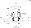
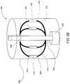
- FIG. 1is a perspective view of an exemplary balloon catheter according to aspects of the disclosure
- FIG. 2is a diagrammatic view illustrating the elliptical dimensions of a native valve annulus that may be determined according to aspects of the disclosure.
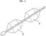
- FIGS. 3A and 3Bare schematic perspective views of a portion of a catheter in which sensing coils are placed on splines extending from the shaft of the catheter according to one aspect of the disclosure.
- FIG. 4is a block diagram illustrating an exemplary system for determining the dimensions of a native valve annulus according to aspects of the disclosure.
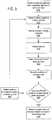
- FIG. 5is a flow chart depicting a method for determining the locations of sensing coils to determine the geometry of a native valve annulus according to one aspect of the disclosure.
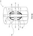
- FIGS. 6A and 6Bare schematic perspective views of a portion of a catheter in which sensing coils are placed on splines extending from the shaft of the catheter according to another aspect of the disclosure.
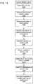
- FIG. 7is a flow chart depicting a method for determining the locations of sensing coils to determine the geometry of a native valve annulus according to another aspect of the disclosure.
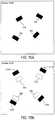
- FIGS. 8A-8Care diagrammatic views illustrating a display of the sensing coils according to one aspect of the disclosure.
- FIG. 9is a diagrammatic view illustrating an example of determining the three-dimensional geometry of a native valve annulus according to aspects of the disclosure.
- FIG. 10is a flow chart depicting a method for determining the three-dimensional geometry of a native valve annulus according to aspects of the disclosure.
- FIGS. 11A and 11Bare schematic perspective views of a portion of a balloon catheter in which sensing coils are placed on splines extending from the shaft of the catheter according to one aspect of the disclosure.
- FIG. 12is a flow chart depicting a method for determining the compliance of the valve annulus according to one aspect of the disclosure.
- FIGS. 13A and 13Bare schematic perspective views of a portion of a balloon catheter in which sensing coils are placed on splines extending from the shaft of the catheter according to another aspect of the disclosure.
- FIG. 14is a flow chart depicting a method for determining the compliance of the valve annulus according to another aspect of the disclosure.
- FIGS. 15A and 15Bare diagrammatic views illustrating a display of the sensing coils according to one embodiment of the disclosure.
- the words “substantially,” “approximately,” “generally,” and “about”are intended to mean that slight variations from absolute are included within the scope of the structure or process recited. Additionally, the terms “proximal,” “distal,” “leading,” and “trailing” are to be taken as relative to a user using the disclosed catheter. “Proximal” or “trailing end” are to be understood as relatively close to the user and “distal” or “leading end” are to be understood as relatively farther away from the user.
- the native valve annulusmay be a valve annulus in which a trans-catheter aortic valve is to be implanted.
- the native valve annulusmay also be that in which another type of trans-catheter cardiac valve is to be implanted, such as a mitral valve, a tricuspid valve, or a pulmonary valve.
- the native valve annulusmay refer to a prosthetic valve previously implanted in a patient which has subsequently become diseased, requiring further intervention using a new trans-catheter valve implantation procedure (“valve-in-valve” implantation).
- the disclosed system and methoduse sensing coils to detect generated magnetic fields to determine the dimensions and compliance of the native valve annulus.
- the systems and methods described hereincan be used to determine dimensions and compliance of the valve annulus post valvuloplasty and prior to prosthetic valve implantation.
- a balloon catheter positioned in the native valve annulusis inflated with saline, flattening the native valve leaflets, which are typically diseased and/or calcified.
- a non-compliant balloonis typically used for this purpose.
- the disclosed system and methodmay add another balloon, typically a compliant balloon, either proximal or distal to the valvuloplasty balloon.
- FIG. 1illustrates one example of a non-compliant balloon 102 having a compliant balloon 104 placed adjacent to it.
- the operatormay inflate and deflate the non-compliant balloon 102 to perform a balloon valvuloplasty procedure, then either advance or retract the catheter and inflate the compliant (i.e., sizing) balloon 104 to measure the dimensions of the native valve annulus.
- the compliant ballooni.e., sizing
- the compliant balloon 104may share a fluid lumen with the non-compliant balloon 102 .
- the fluid lumensmay be separate.
- the compliant balloon 104When inflated, the compliant balloon 104 may conform to the native valve annulus such that the walls of the balloon 104 contact substantially the entire circumference of the native valve annulus or as much of the circumference of the native valve annulus as is physically possible (e.g., there may be slight gaps between the balloon wall and the circumference of the native valve annulus).
- a device incorporating only a compliant balloonmay be used for sizing the native valve annulus.
- FIG. 2illustrates an example of the dimensions of the native valve annulus that may be measured by the systems and methods described herein.
- sizing of the native valve annulus with a sizing balloonmay be performed by determining the positions, such as location and orientation, of sensing coils positioned within the native valve annulus.
- the positions of the sensing coilsmay be stored in a memory or displayed (or both).
- the sensing coilsmay then be repositioned and redeployed in the native valve annulus. Again, the positions of the sensing coils may be determined and stored.
- the systemmay connect the various data points via line segments or smooth curves to form an ellipse around the data points. With this procedure, the dimensions of the native valve annulus may be determined.
- the dimensionsmay include the major axis length 202 , a minor axis length 204 , perimeter 206 , area, area and perimeter averaged length of the annulus. According to some embodiments, the major axis length 202 and the minor axis length 204 may be approximated or estimated and within a degree of confidence. From these dimensions, other aspects of the native valve annulus may also be determined, such as its eccentricity.
- FIGS. 3A and 3Bare schematic perspective views of a sensing catheter 302 according to one aspect of the disclosure.
- the sensing cathetermay include a shaft 306 having a leading end and a trailing end.
- shaft 306may have a lumen for a guide wire.
- a plurality of splines 308 , 310 , 312 , and 314may be attached in an array near the leading end of shaft 306 . More particularly, the end of each spline closest to the leading end of shaft 306 may be fixedly attached to the shaft. The other end of each spline may be attached to a ring 328 that is free to slide on shaft 306 .
- splines 308 , 310 , 312 , and 314are shown as fixedly attached to the leading end of shaft 306 and the ring 328 , one of ordinary skill in the art would recognize that other orientations may be employed.
- splines 308 , 310 , 312 , and 314may be fixedly attached to a trailing portion of shaft 306 and to ring 328 , which may be slidably mounted toward the leading end of shaft 306 .
- splines 308 , 310 , 312 and 314are deployed by retracting a spline sheath 326 (as described in greater detail below), they will bow radially outwardly from shaft 306 to an expanded condition. This outward bowing will cause ring 328 to slide in a distal direction toward the leading end of shaft 306 . Conversely, during re-sheathing the sliding ring 328 will move proximally and the splines 308 , 310 , 312 , and 314 will move from the expanded condition radially inward to a contracted condition closer to shaft 306 .
- the ease with which splines 308 , 310 , 312 and 314 may be moved between the contracted and expanded conditionsenables their easy deployment and re-sheathing without causing significantly large residual stresses.
- splines 308 , 310 , 312 , and 314may be struts formed from a shape-memory material, such as Nitinol, and heat set in an expanded condition so that the spline array self-expands to the expanded condition upon deployment.
- the spline arrayWhen unconstrained, the spline array may expand radially outward to a diameter that is larger than the largest cardiac valve annulus diameter (typically around 30 mm for the aortic valve in humans).
- the diameter of the expanded spline arraymay be between about 1 FR and about 3 FR.
- the diameter of the expanded spline arraymay be about 2 FR.
- sensing catheter 302may have any number of splines spaced around shaft 306 . According to preferred embodiments, the splines may be equally-spaced around shaft 306 .
- Each splinemay have at least one sensing coil mounted thereon. As shown in FIGS. 3A and 3B , a first sensing coil 316 may be mounted on spline 308 , a second sensing coil 318 may be mounted on spline 310 , a third sensing coil 320 may be mounted on spline 312 , and a fourth sensing coil 322 may be mounted on spline 314 .
- the sensing coilsmay be any sensing coils suitable for medical purposes and capable of measuring induced voltage due to variations in magnetic flux. In some embodiments, sensing coils 316 , 318 , 320 , and 322 may be mounted along the waist or expansion center (i.e., equator) of each spline.
- the sensing coilsmay be located in different planes perpendicular to the shaft 306 to provide three-dimensional information of the native valve annulus. In a further embodiment, multiple sensing coils may be positioned on each spline to obtain three-dimensional information relevant to the valve annulus.
- the sensing coilsmay be between about 0.5 mm and about 4.5 mm long. In preferred embodiments, the sensing coils may be about 1 mm long.
- sensing catheter 302may include a spline sheath 326 that is allowed to slide relative to shaft 306 and to splines 308 , 310 , 312 and 314 .
- the spline sheathmay keep the splines in the contracted condition, shown in FIG. 3A , as the sensing catheter is delivered to a native valve annulus.
- spline sheath 326may be retracted using any known technique to deploy the splines to the expanded condition shown in FIG. 3B .
- the sensing cathetermay include a non-compliant or semi-compliant balloon 304 formed of a suitable material positioned inside of splines 308 , 310 , 312 and 314 .
- the ends of balloon 304may be bonded to shaft 306 .
- a fluid lumen and aperture (not shown) in shaft 306may supply a pressurized homogeneous medium (e.g., saline) for inflating balloon 304 .
- a pressurized homogeneous mediume.g., saline
- a small incremental additional pressuremay be applied to the balloon 304 , resulting in a small and measureable displacement of the sensing coils on the splines.
- sensing catheter 302may determine the dimensions of the native valve annulus, whereas using a non-compliant or semi-compliant balloon allows the sensing catheter 302 to determine both the dimensions and the compliance of the native valve annulus.
- FIG. 4illustrates an exemplary system 4000 for detecting the positions of the sensing coils deployed via the sensing catheter and for determining from those positions the dimensions, eccentricity, and compliance of a native valve annulus.
- the system 4000may include a magnetic tracking system 4002 , a transmitter 4030 , and the sensing catheter 302 .
- the magnetic tracking system 4002may include a processor 4004 , a display 4006 , and a non-transitory, computer-readable memory 4008 .
- the magnetic tracking system 4002may be a personal computer, intended for use by a user, having all the components normally found in a personal computer, such as a central processing unit (CPU), display device, CD-ROM, hard drive, user inputs, speakers, modem and/or network interface device, and all of the components used for connecting these elements to one another.
- the magnetic tracking system 4002may be any computing device, such as a server, tablet, mobile device, smart phone, phablet, etc.
- the magnetic tracking system 4002may be specialized computing equipment, such as a Mediguide® system (available from Mediguide Ltd. of Haifa, Israel).
- the magnetic tracking system 4002may be in communication with transmitter 4030 and sensing catheter 302 .
- the processor 4004may be any conventional processor, such as a commercially available CPU. Alternatively, the processor 4004 may be a dedicated device, such as an Application Specific Integrated Circuit (ASIC), a Field Programmable Gate Array (FPGA), or other programmable, hardware-based processor. Additionally, the processor 4004 may include multiple processors, multi-core processors, or a combination thereof. Accordingly, references to a processor will be understood to include references to a collection of processors or dedicated logic that may or may not operate in parallel.
- ASICApplication Specific Integrated Circuit
- FPGAField Programmable Gate Array
- the display 4006may include any display capable of rendering data visually.
- the display 4006may include a monitor, such as an LED or plasma display.
- display 4006may represent the positions of the sensing coils dynamically in real time at 10-30 frames per second. While display 4006 is shown as a component integrated into magnetic tracking system 4002 , one of ordinary skill in the art would recognize that display 4006 may be a stand-alone device. Further, display 4006 may be located remotely from the magnetic tracking system 4002 . For example, the data gathered by magnetic tracking system 4002 may be transmitted over a network to display 4006 to be viewed remotely.
- the memory 4008may be any memory capable of storing information accessible by the processor 4004 , including data 4010 and instructions 4020 that may be executed or otherwise used by the processor.
- the memory 4008may be of any type capable of storing information accessible by the processor, including a non-transitory, computer-readable medium, or other medium that stores data that may be read with the aid of an electronic device, such as a hard-drive, memory card, flash drive, ROM, RAM, DRAM, DVD or other optical disks, as well as other write-capable and read-only memories.
- the memorymay include short term or temporary storage as well as long term or persistent storage.
- the memory 4008may include a storage area network (SAN) capable of being accessed by magnetic tracking system 4002 .
- Storage systems and methodsmay include different combinations of the foregoing, whereby different portions of the instructions and data may be stored on different types of media.
- the data 4010may include annulus dimensions and compliance information 4012 and received coil output 4014 from the sensing catheter 302 .
- the data 4010may be retrieved, stored, or modified by processor 4004 in accordance with instructions 4020 . Additionally, the data 4010 may be outputted to display 4006 in accordance with instructions 4020 .
- the datamay be formatted in any computer-readable format, and may comprise any information sufficient to identify the relevant information, such as numbers, descriptive text, proprietary codes, references to data stored in other areas of the same memory or different memories (including other network locations) or information that is used to calculate the relevant data.
- the instructions 4020may be any set of instructions to be executed by the processor 4004 .
- the instructionsmay be stored as computer code on the non-transitory, computer-readable medium.
- the terms “instructions,” “modules,” and “programs”may be used interchangeably herein.
- the instructionsmay include instructions 4022 for driving the transmitter, instructions 4024 for determining and displaying the positions of the sensing coils and instructions 4026 for determining the dimensions, eccentricity and compliance of an annulus from the measured potentials. Functions, methods and routines of the instructions are explained in more detail below.
- the transmitter 4030may be any transmitting device capable of generating a number of distinct magnetic fields 4032 .
- the transmitter 4030may include an array of drive coils at fixed and previously established locations proximate to the navigation region of interest.
- the transmitter 4030may be located beneath a patient's bed, mounted to the side of a patient's bed, or located on another instrument, such as a fluoroscopy head.
- the transmittermay generate magnetic fields, typically in a range of 1 to 20 kilohertz. Accordingly, each drive coil may induce potentials in the sensing coils of the sensing catheter 302 by virtue of slightly different drive frequencies for each drive coil.
- the location and orientation of any sensing coil in a catheter or other instrumentmay be determined in real time.
- the magnetic tracking systemmay determine the location and/or orientation of each of the sensing coils in catheter 302 described above. Sub-millimeter accuracy of the location and orientation of the coils has been established using the Mediguide® system. While the transmitter 4030 is illustrated as a separate component from the magnetic tracking system 4002 , one of ordinary skill in the art would recognize that the magnetic tracking system 4002 and the transmitter 4030 may be located in the same housing.
- FIG. 5illustrates a method for assessing the cross-sectional dimensions and compliance of a native valve annulus which may be performed using system 4000 or any other capable system.
- sensing catheter 302with balloon 304 deflated and splines 308 , 310 , 312 and 314 in a collapsed state, may be advanced to the native valve annulus over a guide wire.
- spline sheath 326may be retracted in block 520 to deploy the splines.
- the splinesexpand radially outward as they are deployed until sensing coils 316 , 318 , 320 and 322 contact the periphery of the native valve annulus.
- balloon 304may be inflated in block 540 using saline or other fluid. As balloon 304 inflates, it may conform to the shape of the native valve annulus. In doing so, balloon 304 may push one or more of splines 308 , 310 , 312 and 314 outwardly to ensure that each of sensing coils 316 , 318 , 320 and 322 is in contact with the native valve annulus.
- system 4000may be employed to determine the positions of the sensing coils and, from that information, the size and shape of the native valve annulus. More particularly, in block 550 , magnetic tracking system 4002 may be used to determine the three-dimensional positions of sensing coils 316 , 318 , 320 and 322 . Magnetic tracking system 4002 may send instructions to transmitter 4030 to begin generating magnetic fields 4032 . Each drive coil in transmitter 4030 may use a slightly different drive frequency to generate a number of distinct magnetic fields at fixed and previously established locations proximate to the navigation region of interest. Each distinct magnetic field may generate a potential at each of the sensing coils.
- the potentials induced in the sensing coilsmay be transmitted to the magnetic tracking system 4002 as sensing coil output 4034 .
- the magnetic tracking system 4002may amplify the sensing coil output 4034 and convert it to a real time digital amplitude representation.
- the position (e.g., location, orientation, etc.) of any sensing coil in a catheter or other instrumentmay be determined in real time.
- the magnetic tracking system 4002may determine the location and/or orientation of each of the sensing coils and output the location and/or orientation of each of the sensing coils via display 4006 .
- determining the position of each sensing coilmay include representing the position of each sensing coil graphically on a display or another computing device, such as a computer, tablet, etc.
- the positions of the sensing coilsmay be represented dynamically in real time at 10-30 frames per second. Displaying the sensing coils in real time may provide an indication of the degree of calcification of the native valve annulus. For example, the sensing coils that are less dynamic or that traverse a shorter distance during a cardiac cycle may indicate a greater degree of calcification in that region of the valve annulus.
- the positions of the sensing coilsmay be recorded either by storing them in memory or plotting them graphically, for example, on a Cartesian plane.
- a determinationis made with respect to whether enough data points have been collected. For example, the system may need a predetermined number of sensing coil locations to provide an accurate measurement of the native valve annulus. If an insufficient number of data points have been collected, in block 580 , balloon 304 may be deflated and sheath 326 advanced to move the splines 308 , 310 , 312 and 314 to the collapsed condition.
- the cathetermay then be rotated and the process of deploying the splines and acquiring the positions of the sensing coils in the same plane of the native valve annulus as the first data set is repeated. If the system determines in block 570 that the predetermined number of data points have been collected, in block 590 the system determines the geometry of the annulus based on the determined locations of the sensing coils.
- FIGS. 6A and 6Bare schematic perspective views of a sensing catheter 602 according to another aspect of the disclosure.
- Sensing catheter 602is similar to sensing catheter 302 described above with respect to FIGS. 3A and 3B .
- sensing catheter 602differs from sensing catheter 302 in that the sensing coils are located within balloon 604 .
- balloon 604may be a compliant balloon.
- sensing catheter 602may hold the leaflets of the native valve annulus back and prevent the leaflets from prolapsing.
- the compliant balloonwill conform to the shape of the native valve annulus.
- sensing catheter 602is shown with balloon 604 in a deflated state and the splines maintained in a contracted condition by spline sheath 326 .
- a fluid lumen and aperture in shaft 306may supply a pressurized homogeneous medium (e.g., saline) for inflating balloon 604 .
- spline sheath 326may be retracted using any known technique, thereby allowing splines 308 , 310 , 312 , and 314 to expand radially outward as shown in FIG. 6B .
- Splines 308 , 310 , 312 , and 314may expand outwardly such that sensing coils 316 , 318 , 320 , and 322 contact the inner wall of balloon 604 . Accordingly, sensing coils 316 , 318 , 320 , and 322 may be used to determine the dimensions of the native valve annulus.
- FIG. 7illustrates a method for assessing the cross-sectional dimensions of a native valve annulus using the sensing catheter depicted in FIGS. 6A and 6B , which may be performed using system 4000 or any other capable system.
- the sensing catheterwith the balloon deflated and the splines in a collapsed state, may be advanced to the native valve annulus over a guide wire.
- balloon 604may be inflated such that it conforms to the shape of the native valve annulus.
- spline sheath 326may be retracted in block 730 to deploy the splines.
- the splinesexpand radially outward as they are deployed until the sensing coils contact the inner wall of balloon 604 .
- system 4000may be employed to determine the positions of the sensing coils and, from that information, the size and shape of the native valve annulus.
- magnetic tracking system 4002may be used to determine the three-dimensional positions of sensing coils 316 , 318 , 320 , and 322 by representing the position of each sensing coil graphically on a display.
- the positions of the sensing coilsmay be recorded in memory or plotted graphically in block 760 , and sheath 326 may be advanced to move splines 308 , 310 , 312 , and 314 to the collapsed state.
- FIGS. 8A-8Cillustrate an example of determining the geometry of the native valve annulus in accordance with the methods described above.
- FIG. 8Ashows the positions of the sensing coils on the display 4006 .
- the first location of the first sensing coil 316may be indicated by the data point 316 ′
- the first location of the second sensing coil 318may be indicated by the data point 318 ′
- the first location of the third sensing coil 320may be indicated by the data point 320 ′
- the first location of the fourth sensing coil 322may be indicated by the data point 322 ′.
- the position of the sensing cathetermay be adjusted to acquire another set of data points in the same plane.
- FIG. 8Ashows the positions of the sensing coils on the display 4006 .
- the first location of the first sensing coil 316may be indicated by the data point 316 ′
- the first location of the second sensing coil 318may be indicated by the data point 318 ′
- FIG. 8Bshows the second location of the first sensing coil 316 as indicated by the data point 316 ′′, the second location of the second sensing coil 318 as indicated by the data point 318 ′′, the second location of the third sensing coil 320 as indicated by the data point 320 ′′, and the second location of the fourth sensing coil 322 as indicated by the data point 322 ′′.
- the systemmay connect adjacent data points with line segments or a smooth curve to create a visual image of the valve annulus cross-section.
- a smooth curveis fitted to the set of points collected.
- an ellipsecan be fitted to the set of data points.
- FIG. 8Cshows an example of the geometry of a native valve annulus as determined by the foregoing procedure. In particular, FIG. 8C illustrates a smooth curve 806 fitted to the set of data points.
- Smooth curve 806may represent the perimeter of the native valve annulus. Further, the major axis length 202 and the minor axis length 204 may be determined from the set of data points collected. Accordingly, the information displayed in FIG. 8C may be used to determine additional information for the native valve annulus, such as the area and area and perimeter averaged length of the annulus.
- the sensing catheters described hereinmay be used to obtain three-dimensional information about the native valve annulus.
- FIG. 9a cross-section of a native aortic valve is shown.
- Three-dimensional information for the valvemay be constructed by determining the valve geometry, as described above, at different planes of the native valve annulus (e.g., at planes 910 , 920 , 930 , 940 , 950 , and 960 ).
- the method depicted in either FIG. 5 or 7may be performed at a first plane 910 .
- the cathetermay then be translated so that the sensing coils are at about plane 920 , and the method may be repeated.
- the cathetermay again be translated and the method repeated at each of the remaining planes (e.g., 930 , 940 , 950 , and 960 ).
- the information gathered at each planemay be collated to develop three-dimensional information for the native valve annulus.
- the three-dimensional informationmay be used to decide the best landing spot for the deployment of a prosthetic valve, thereby minimizing paravalvular leakage when an appropriately-sized transcatheter valve is used.
- the three-dimensional informationmay be depicted graphically or numerically, depending on the needs of the user.
- the sensing cathetermay obtain the dimensions of the native valve annulus at a first plane.
- the steps to obtain those dimensionsmay be those depicted in the flow chart of either FIG. 5 or 7 .
- a determinationis made as to whether the dimensions of the native valve annulus may be obtained at a different plane. If it is determined that the dimensions at an additional plane may be obtained, the method proceeds to block 1030 at which the dimensions at another plane are obtained.
- the inquiry performed in block 1020may be performed repeatedly until there are no additional planes at which to obtain dimensions of the native valve annulus.
- the methodproceeds to block 1040 at which a 3-D model of the native valve annulus is constructed from the dimensions obtained at the various planes.
- the 3-D model of the native valve annulusmay be constructed after the geometry at a predetermined number of planes has been obtained.
- FIGS. 11A and 11Bare schematic perspective views showing the use of sensing balloon catheter 302 described above (i.e., with balloon 304 positioned inside of splines 308 , 310 , 312 and 314 ) to determine the compliance of the native valve annulus.
- FIG. 11Ashows the sensing balloon catheter 302 after spline sheath 326 has been retracted and non- or semi-compliant balloon 304 has been inflated to a first inflated condition.
- baseline locations of sensing coils 316 , 318 , 320 , and 322may be determined using the methods described above.
- FIG. 11Billustrates the sensing balloon catheter 302 in a second inflated condition in which balloon 304 is at a greater pressure.
- balloon 304may exert a uniform pressure on the native valve annulus similar to the radial force that a stent frame would exert on the native valve annulus.
- the pressure exerted by the balloonmay force the annulus radially outward, whereas noncompliant calcified portions of the annulus will not deform or will deform to a much lesser extent.
- the balloonwill also expand radially, enabling selected ones of the splines to further expand outwardly.
- sensing coils 316 , 318 , 320 , and 322may be displaced.
- sensing coil 1116shows the displacement of sensing coil 316 after balloon 304 has been further inflated.
- sensing coil 1118shows the displacement of sensing coil 318 ;
- sensing coil 1120shows the displacement of sensing coil 320 ;
- sensing coil 1122shows the displacement of sensing coil 322 .
- FIG. 12is a flowchart depicting a method for determining the compliance, or lack thereof, of a native valve annulus using the sensing catheter depicted in FIGS. 11A and 11B .
- the methodbegins in block 1210 with the step of advancing the sensing balloon catheter over a guide wire to a native valve annulus.
- the catheteris advanced with the non- or semi-compliant balloon in the deflated state and the splines in the collapsed state.
- the spline sheathmay be retracted in a known manner to deploy and expand the splines.
- the balloonmay be inflated to a first inflated condition with a homogeneous medium (e.g., saline) until the balloon contacts the splines and, in block 1240 , forces the sensing coils against the native valve annulus.
- a homogeneous mediume.g., saline
- the balloonmay expand until it contacts and conforms to the native valve annulus.
- the positions of the sensing coilsare determined.
- a magnetic tracking systemsuch as the Mediguide® system or the magnetic tracking system 4002 described above, may be used to determine the three-dimensional location of each of the sensing coils.
- the position of each of the sensing coilsmay be recorded. Recording the position of each sensing coil may include storing the position in memory, representing the position of each sensing coil graphically on a computing device, or a combination of both.
- the balloonmay be further inflated to a second inflated condition.
- the balloonmay exert a radial force on the valve annulus similar to the radial force exerted by the stent frame of a prosthetic heart valve.
- the balloonmay increase in diameter, compressing the native valve annulus in some locations more than in others.
- the splineswill be forced further outward until the sensing coils again contact the native valve annulus.
- the displacement of the sensing coilsmay be determined with sub-millimeter accuracy.
- the compliance of the annulus based on the displacement of the sensing coilsis determined, which may be displayed graphically as discussed in greater detail above.
- the native valve annuluswill have a relatively greater compliance where the displacement of the sensing coils is the greatest and a lesser compliance where the displacement of the sensing coils is less, thereby reflecting calcification.
- the methodmay detect varying degrees of calcification of the annulus based on the displacement of the sensing coils, which may be measured with sub-millimeter accuracy. Non-uniform calcification may lead to malapposition of a stent frame, which could cause paravalvular leakage.
- FIGS. 13A and 13Bare schematic perspective views showing the use of sensing balloon catheter 602 described above (i.e., with splines 308 , 310 , 312 and 314 positioned within balloon 604 ) to determine the compliance of the native valve annulus.
- FIG. 13Ashows the sensing balloon catheter 602 after non- or semi-compliant balloon 604 has been inflated to a first inflated condition and spline sheath 326 has been retracted.
- baseline locations of sensing coils 316 , 318 , 320 , and 322may be determined using the methods described above.
- balloon catheter 602is shown with balloon 604 at a greater pressure in a second inflated condition.
- balloon 604may exert a uniform pressure on the native valve annulus similar to the radial force that a stent frame would exert on the native valve annulus.
- one or more (or none) of sensing coils 316 , 318 , 320 , and 322may be displaced.
- sensing coil 1316shows the displacement of sensing coil 316 after balloon 604 has been further inflated.
- sensing coil 1318shows the displacement of sensing coil 318 ;
- sensing coil 1320shows the displacement of sensing coil 320 ; and
- sensing coil 1322shows the displacement of sensing coil 322 .
- FIG. 14illustrates a flow chart depicting a method for determining the compliance of a native valve annulus using the sensing catheter depicted in FIGS. 13A and 13B .
- the methodbegins in block 1410 by advancing the sensing balloon catheter over a guide wire to a native valve annulus.
- the non- or semi-compliant balloonmay be inflated to a first inflated condition with a homogeneous medium.
- the spline sheathmay be retracted in a known manner to deploy and expand the splines.
- the splinesmay expand outwardly until the sensing coils contact the inner wall of the inflated balloon.
- the positions of the sensing coilsmay be determined, and the position of each of the sensing coils may be recorded in block 1460 .
- the balloonmay be further inflated to a second inflated condition.
- the displacement of the sensing coilsmay be determined with sub-millimeter accuracy.
- the compliance of the annulus based on the displacement of the sensing coilsis determined in block 1490 .
- FIGS. 15A and 15Bshow an example in which the displacement of the coils is displayed.
- FIG. 15Ashows the baseline locations of sensing coils 316 , 318 , 320 , and 322 on display 4006 after the initial deployment of the splines.
- FIG. 15Bshows the displacement of the sensing coils after the non- or semi-compliant balloon has been further inflated to the second inflation condition.
- Display 4006may display the locations of the sensing coils shown in FIG. 15A in addition to the locations of the sensing coils following inflation of the balloon to the second inflated condition, as indicated by reference numerals 1316 , 1318 , 1320 , and 1322 .
- the sensing coils that travel a lesser distancemay indicate a greater degree of calcification in that region of the native valve annulus since the native valve annulus would not deform as much in the second inflated condition in areas with greater degrees of calcification.
- a system for determining the dimensions of a native valve annulusmay include a sensing catheter having a shaft extending in a longitudinal direction; a plurality of splines attached to the shaft, the splines having an expanded condition spaced radially outward from the shaft; and at least one sensing coil located on each of the splines; a transmitter configured to generate a magnetic field to induce a potential in each of the sensing coils; and a computing device configured to identify positions of the sensing coils based on the induced potentials; and/or
- the sensing cathetermay include an expandable balloon positioned between the shaft and the splines;
- the transmittermay be an array of drive coils; and/or
- the systemmay include a display configured to output the position of each of the sensing coils;
- the sensing cathetermay include a ring slidably mounted on the shaft, each of the splines having one end attached to the shaft and another end attached to the ring; and/or
- the sensing cathetermay include a spline sheath slidable relative to the shaft between a first position overlying the splines and a second position exposing the splines for movement to the expanded condition.
- a method for determining the dimensions of a native valve annulusmay include delivering a sensing catheter to a native valve annulus, the sensing catheter including a plurality of splines having a contracted condition and a radially expanded condition, each of the splines including a sensing coil; deploying the plurality of splines from the contracted condition to the radially expanded condition; generating at least one magnetic field that induces a potential in each of the sensing coils; determining a first position of each of the sensing coils based on the induced potentials; and determining a dimension of the native valve annulus based on the first positions of the sensing coils; and/or
- the deploying stepmay include deploying the plurality of splines so that the sensing coils are at a first plane relative to the native valve annulus;
- the methodmay further include moving the plurality of splines from the radially expanded condition to the collapsed condition; rotating the sensing catheter to change the positions of the sensing coils; redeploying the plurality of splines from the contracted condition to the radially expanded condition so that the sensing coils are at the first plane relative to the native valve annulus; generating at least one magnetic field that induces a second potential in each of the sensing coils; determining a second position of each of the sensing coils based on the second induced potentials; and determining the dimension of the native valve annulus based on the first and second positions of the sensing coils; and/or
- the methodmay further include creating an image of the first plane of the native valve annulus by displaying first data points representing the first positions of the sensing coils and connecting each first data point with an adjacent first data point; and/or
- the creating stepmay include connecting each first data point with the adjacent first data point using a straight line or fitting a smooth curve to connect all of the first data points;
- the methodmay further include moving the plurality of splines from the radially expanded condition to the collapsed condition; translating the sensing catheter so that the sensing coils are at a second plane different from the first plane relative to the native valve annulus; redeploying the plurality of splines from the contracted condition to the radially expanded condition so that the sensing coils are at the second plane relative to the native valve annulus; generating at least one magnetic field that induces a second potential in each of the sensing coils; determining a second position of each of the sensing coils based on the second induced potentials; and determining a second dimension of the native valve annulus based on the second positions of the sensing coils; and/or
- the methodmay further include creating an image of the second plane of the native valve annulus by displaying second data points representing the second positions of the sensing coils and connecting each second data point with an adjacent second data point; and/or
- the methodmay further include constructing a three-dimensional model of the native valve annulus based on the image of the first plane of the native valve annulus and the image of the second plane of the native valve annulus; and/or
- the sensing cathetermay include a shaft and a balloon positioned between the splines and the shaft, and the deploying step may include inflating the balloon to a first inflated condition between the deploying step and the generating step;
- the methodmay further include inflating the balloon to a second inflated condition after the determining step;
- the methodmay further include, after the step of inflating the balloon to the second inflated catheter, generating at least one magnetic field that induces a second potential in each of the sensing coils; determining a second position of each of the sensing coils based on the second induced potentials; determining a displacement of each of the sensing coils based on the first and second positions; and determining a degree of compliance of the native valve annulus based on the displacement of each of the sensing coils; and/or
- the displacement of each of the sensing coilsmay be the difference between the second position of the sensing coil and the first position of the sensing coil;
- the methodmay further include determining a degree of calcification of the native valve annulus based on the degree of compliance.
- An apparatusmay include a shaft extending in a longitudinal direction; a plurality of splines attached to the shaft, the splines having an expanded condition spaced radially outward from the shaft; at least one sensing coil located on each of the splines; and an expandable balloon positioned between the shaft and the splines.
Landscapes
- Health & Medical Sciences (AREA)
- Life Sciences & Earth Sciences (AREA)
- Cardiology (AREA)
- General Health & Medical Sciences (AREA)
- Public Health (AREA)
- Biomedical Technology (AREA)
- Heart & Thoracic Surgery (AREA)
- Veterinary Medicine (AREA)
- Engineering & Computer Science (AREA)
- Animal Behavior & Ethology (AREA)
- Oral & Maxillofacial Surgery (AREA)
- Transplantation (AREA)
- Vascular Medicine (AREA)
- Dentistry (AREA)
- Physics & Mathematics (AREA)
- Biophysics (AREA)
- Pathology (AREA)
- Medical Informatics (AREA)
- Molecular Biology (AREA)
- Surgery (AREA)
- Prostheses (AREA)
- Media Introduction/Drainage Providing Device (AREA)
Abstract
Description
Claims (14)
Priority Applications (1)
| Application Number | Priority Date | Filing Date | Title |
|---|---|---|---|
| US15/088,224US10716672B2 (en) | 2015-04-07 | 2016-04-01 | System and method for intraprocedural assessment of geometry and compliance of valve annulus for trans-catheter valve implantation |
Applications Claiming Priority (2)
| Application Number | Priority Date | Filing Date | Title |
|---|---|---|---|
| US201562143968P | 2015-04-07 | 2015-04-07 | |
| US15/088,224US10716672B2 (en) | 2015-04-07 | 2016-04-01 | System and method for intraprocedural assessment of geometry and compliance of valve annulus for trans-catheter valve implantation |
Publications (2)
| Publication Number | Publication Date |
|---|---|
| US20160296333A1 US20160296333A1 (en) | 2016-10-13 |
| US10716672B2true US10716672B2 (en) | 2020-07-21 |
Family
ID=55755738
Family Applications (1)
| Application Number | Title | Priority Date | Filing Date |
|---|---|---|---|
| US15/088,224Active2037-02-04US10716672B2 (en) | 2015-04-07 | 2016-04-01 | System and method for intraprocedural assessment of geometry and compliance of valve annulus for trans-catheter valve implantation |
Country Status (3)
| Country | Link |
|---|---|
| US (1) | US10716672B2 (en) |
| EP (1) | EP3280359A1 (en) |
| WO (1) | WO2016164257A1 (en) |
Families Citing this family (22)
| Publication number | Priority date | Publication date | Assignee | Title |
|---|---|---|---|---|
| US20170035358A1 (en)* | 2015-08-07 | 2017-02-09 | Boston Scientific Scimed Inc. | Force sensing catheters having super-elastic structural strain sensors |
| AU2017212715B2 (en) | 2016-01-29 | 2019-08-08 | Boston Scientific Scimed, Inc. | Force sensing catheter with impedance-guided orientation |
| US11369431B2 (en) | 2016-06-11 | 2022-06-28 | Boston Scientific Scimed Inc. | Inductive double flat coil displacement sensor |
| US10653523B2 (en) | 2017-01-19 | 2020-05-19 | 4C Medical Technologies, Inc. | Systems, methods and devices for delivery systems, methods and devices for implanting prosthetic heart valves |
| US10561495B2 (en) | 2017-01-24 | 2020-02-18 | 4C Medical Technologies, Inc. | Systems, methods and devices for two-step delivery and implantation of prosthetic heart valve |
| US12029647B2 (en) | 2017-03-07 | 2024-07-09 | 4C Medical Technologies, Inc. | Systems, methods and devices for prosthetic heart valve with single valve leaflet |
| CN110505841B (en)* | 2017-04-05 | 2022-09-23 | 美敦力瓦斯科尔勒公司 | Sizing catheters, methods of sizing complex anatomical structures, and methods of selecting prostheses for implantation |
| US12036113B2 (en) | 2017-06-14 | 2024-07-16 | 4C Medical Technologies, Inc. | Delivery of heart chamber prosthetic valve implant |
| KR102101067B1 (en)* | 2017-10-24 | 2020-04-14 | 한양대학교 산학협력단 | Device and method for plasma treatment |
| CN108891269B (en)* | 2018-05-22 | 2021-10-22 | 广西电网有限责任公司电力科学研究院 | A wireless power receiving device and wireless charging car |
| US12161551B2 (en)* | 2018-08-30 | 2024-12-10 | Edwards Lifesciences Corporation | Systems and methods for sizing and implanting prosthetic heart valves |
| US11857441B2 (en) | 2018-09-04 | 2024-01-02 | 4C Medical Technologies, Inc. | Stent loading device |
| US11452628B2 (en) | 2019-04-15 | 2022-09-27 | 4C Medical Technologies, Inc. | Loading systems for collapsible prosthetic heart valve devices and methods thereof |
| US11931253B2 (en) | 2020-01-31 | 2024-03-19 | 4C Medical Technologies, Inc. | Prosthetic heart valve delivery system: ball-slide attachment |
| US12133797B2 (en) | 2020-01-31 | 2024-11-05 | 4C Medical Technologies, Inc. | Prosthetic heart valve delivery system: paddle attachment feature |
| CN115605127A (en)* | 2020-02-04 | 2023-01-13 | Dp控股(英国)有限公司(Gb) | Devices and methods for selecting stents |
| US12053375B2 (en) | 2020-03-05 | 2024-08-06 | 4C Medical Technologies, Inc. | Prosthetic mitral valve with improved atrial and/or annular apposition and paravalvular leakage mitigation |
| US11992403B2 (en) | 2020-03-06 | 2024-05-28 | 4C Medical Technologies, Inc. | Devices, systems and methods for improving recapture of prosthetic heart valve device with stent frame having valve support with inwardly stent cells |
| CN111568426B (en)* | 2020-05-25 | 2023-03-24 | 易荔 | Airway stenosis section diameter and length measuring device |
| CN112842324A (en)* | 2021-01-07 | 2021-05-28 | 复旦大学 | Balloon type heart valve in-vivo measuring device |
| CN113244504B (en)* | 2021-05-12 | 2022-08-26 | 张智 | Non-permanent coronary artery internal supporting device in saccule dilatation interventional therapy process |
| CN117204981A (en)* | 2022-06-02 | 2023-12-12 | 杭州启明医疗器械股份有限公司 | A multi-plane based heart valve determination method, device and electronic equipment |
Citations (202)
| Publication number | Priority date | Publication date | Assignee | Title |
|---|---|---|---|---|
| US3657744A (en) | 1970-05-08 | 1972-04-25 | Univ Minnesota | Method for fixing prosthetic implants in a living body |
| US4275469A (en) | 1979-12-13 | 1981-06-30 | Shelhigh Inc. | Prosthetic heart valve |
| US4491986A (en) | 1976-05-12 | 1985-01-08 | Shlomo Gabbay | Heart valve |
| US4759758A (en) | 1984-12-07 | 1988-07-26 | Shlomo Gabbay | Prosthetic heart valve |
| US4878906A (en) | 1986-03-25 | 1989-11-07 | Servetus Partnership | Endoprosthesis for repairing a damaged vessel |
| US4922905A (en) | 1985-11-30 | 1990-05-08 | Strecker Ernst P | Dilatation catheter |
| US4994077A (en) | 1989-04-21 | 1991-02-19 | Dobben Richard L | Artificial heart valve for implantation in a blood vessel |
| WO1991017720A1 (en) | 1990-05-18 | 1991-11-28 | Henning Rud Andersen | A valve prosthesis for implantation in the body and a catheter for implantating such valve prosthesis |
| US5411552A (en) | 1990-05-18 | 1995-05-02 | Andersen; Henning R. | Valve prothesis for implantation in the body and a catheter for implanting such valve prothesis |
| US5480423A (en) | 1993-05-20 | 1996-01-02 | Boston Scientific Corporation | Prosthesis delivery |
| US5553611A (en) | 1994-01-06 | 1996-09-10 | Endocardial Solutions, Inc. | Endocardial measurement method |
| WO1997016133A1 (en) | 1995-11-01 | 1997-05-09 | Biocompatibles Limited | Braided stent |
| US5662108A (en) | 1992-09-23 | 1997-09-02 | Endocardial Solutions, Inc. | Electrophysiology mapping system |
| EP0850607A1 (en) | 1996-12-31 | 1998-07-01 | Cordis Corporation | Valve prosthesis for implantation in body channels |
| WO1998032412A2 (en) | 1997-01-24 | 1998-07-30 | Scimed Life Systems Inc | Bistable spring construction for a stent and other medical apparatus |
| US5843167A (en) | 1993-04-22 | 1998-12-01 | C. R. Bard, Inc. | Method and apparatus for recapture of hooked endoprosthesis |
| US5855601A (en) | 1996-06-21 | 1999-01-05 | The Trustees Of Columbia University In The City Of New York | Artificial heart valve and method and device for implanting the same |
| US5865801A (en)* | 1995-07-18 | 1999-02-02 | Houser; Russell A. | Multiple compartmented balloon catheter with external pressure sensing |
| WO1999013801A1 (en) | 1997-09-16 | 1999-03-25 | Zadno Azizi Gholam Reza | Body fluid flow control device |
| US5908448A (en)* | 1993-09-30 | 1999-06-01 | Boston Scientific Corporation | Controlled deployment of a medical device |
| US5935163A (en) | 1998-03-31 | 1999-08-10 | Shelhigh, Inc. | Natural tissue heart valve prosthesis |
| US5961513A (en) | 1996-01-19 | 1999-10-05 | Ep Technologies, Inc. | Tissue heating and ablation systems and methods using porous electrode structures |
| US5961549A (en) | 1997-04-03 | 1999-10-05 | Baxter International Inc. | Multi-leaflet bioprosthetic heart valve |
| EP1000590A1 (en) | 1998-11-09 | 2000-05-17 | Cordis Corporation | An improved stent which is easly recaptured and repositioned within the body |
| US6077297A (en) | 1993-11-04 | 2000-06-20 | C. R. Bard, Inc. | Non-migrating vascular prosthesis and minimally invasive placement system therefor |
| DE19857887A1 (en) | 1998-12-15 | 2000-07-06 | Fraunhofer Ges Forschung | Anchoring support for a heart valve prosthesis comprises a single-piece component which is formed of rod shaped elements made of a memory metal, and has at least in part a lattice structure |
| US6090140A (en) | 1999-02-17 | 2000-07-18 | Shelhigh, Inc. | Extra-anatomic heart valve apparatus |
| WO2001028459A1 (en) | 1999-10-21 | 2001-04-26 | Scimed Life Systems, Inc. | Implantable prosthetic valve |
| WO2001049213A2 (en) | 1999-12-31 | 2001-07-12 | Advanced Bio Prosthetic Surfaces, Ltd. | Endoluminal cardiac and venous valve prostheses and methods of manufacture and delivery thereof |
| US6264691B1 (en) | 1999-04-23 | 2001-07-24 | Shlomo Gabbay | Apparatus and method for supporting a heart valve |
| WO2001054625A1 (en) | 2000-01-31 | 2001-08-02 | Cook Biotech Incorporated | Stent valves and uses of same |
| WO2001056500A2 (en) | 2000-02-03 | 2001-08-09 | Cook Incorporated | Implantable vascular device |
| WO2001076510A2 (en) | 2000-04-06 | 2001-10-18 | Edwards Lifesciences Corporation | Minimally-invasive heart valves and methods of use |
| US20020036220A1 (en) | 2000-09-26 | 2002-03-28 | Shlomo Gabbay | Curved implantable sheath and method of making same |
| US6368348B1 (en) | 2000-05-15 | 2002-04-09 | Shlomo Gabbay | Annuloplasty prosthesis for supporting an annulus of a heart valve |
| WO2002036048A1 (en) | 2000-10-31 | 2002-05-10 | Jacques Seguin | Tubular support for setting, by percutaneous route, a substitution cusp |
| WO2002047575A2 (en) | 2000-12-15 | 2002-06-20 | Angiomed Gmbh & Co. Medizintechnik Kg | Stent with valve |
| US20020087208A1 (en)* | 1997-12-03 | 2002-07-04 | Scimed Life Systems, Inc. | Devices and methods for creating lesions in endocardial and surrounding tissue to isolate focal arrhythmia substrates |
| US6419695B1 (en) | 2000-05-22 | 2002-07-16 | Shlomo Gabbay | Cardiac prosthesis for helping improve operation of a heart valve |
| US6468660B2 (en) | 2000-12-29 | 2002-10-22 | St. Jude Medical, Inc. | Biocompatible adhesives |
| DE10121210A1 (en) | 2001-04-30 | 2002-11-14 | Universitaetsklinikum Freiburg | Replacement heart valve, comprises an anchoring element, and has a starting volume which is opened up to the normal volume using a catheter |
| US6498944B1 (en)* | 1996-02-01 | 2002-12-24 | Biosense, Inc. | Intrabody measurement |
| US20030023303A1 (en) | 1999-11-19 | 2003-01-30 | Palmaz Julio C. | Valvular prostheses having metal or pseudometallic construction and methods of manufacture |
| US6517576B2 (en) | 2000-12-11 | 2003-02-11 | Shlomo Gabbay | Implantable patch prosthesis having one or more cusps for improved competency |
| US20030050694A1 (en) | 2001-09-13 | 2003-03-13 | Jibin Yang | Methods and apparatuses for deploying minimally-invasive heart valves |
| US6533810B2 (en) | 1995-11-27 | 2003-03-18 | Schneider (Europe) Ag | Conical stent |
| WO2003047468A1 (en) | 2001-10-11 | 2003-06-12 | Percutaneous Valve Technologies | Implantable prosthetic valve |
| US6582464B2 (en) | 2000-05-03 | 2003-06-24 | Shlomo Gabbay | Biomechanical heart valve prosthesis and method for making same |
| US20030120318A1 (en) | 1998-06-30 | 2003-06-26 | Hauck John A. | Congestive heart failure pacing optimization method and device |
| US20030130726A1 (en) | 1999-09-10 | 2003-07-10 | Thorpe Patricia E. | Combination valve and stent for treating vascular reflux |
| US6623518B2 (en) | 2001-02-26 | 2003-09-23 | Ev3 Peripheral, Inc. | Implant delivery system with interlock |
| EP1360942A1 (en) | 2002-05-11 | 2003-11-12 | Willy Rüsch GmbH | Stent |
| US6685625B2 (en) | 2000-09-26 | 2004-02-03 | Shlomo Gabbay | Curved implantable sheath and method of making same |
| US6690963B2 (en)* | 1995-01-24 | 2004-02-10 | Biosense, Inc. | System for determining the location and orientation of an invasive medical instrument |
| US6719789B2 (en) | 1993-11-01 | 2004-04-13 | 3F Therapeutics, Inc. | Replacement heart valve |
| FR2850008A1 (en) | 2003-01-17 | 2004-07-23 | Daniel Roux | Vascular prosthesis has tube and collar for adapting to blood vessel ends of different diameters |
| US6783556B1 (en) | 2000-09-26 | 2004-08-31 | Shlomo Gabbay | System and method for making a calotte-shaped implantable sheath |
| US20040210304A1 (en) | 1999-11-17 | 2004-10-21 | Corevalve, S.A. | Prosthetic valve for transluminal delivery |
| US6814746B2 (en) | 2002-11-01 | 2004-11-09 | Ev3 Peripheral, Inc. | Implant delivery system with marker interlock |
| US20040249267A1 (en)* | 2002-04-17 | 2004-12-09 | Pinhas Gilboa | Endoscope structures and techniques for navigating to a target in branched structure |
| US6830584B1 (en) | 1999-11-17 | 2004-12-14 | Jacques Seguin | Device for replacing a cardiac valve by percutaneous route |
| US6869444B2 (en) | 2000-05-22 | 2005-03-22 | Shlomo Gabbay | Low invasive implantable cardiac prosthesis and method for helping improve operation of a heart valve |
| US20050096726A1 (en) | 2000-05-30 | 2005-05-05 | Jacques Sequin | Noncylindrical stent deployment system for treating vascular bifurcations |
| US20050137695A1 (en) | 2003-12-23 | 2005-06-23 | Sadra Medical | Replacement valve and anchor |
| US20050137697A1 (en) | 2003-12-23 | 2005-06-23 | Amr Salahieh | Leaflet engagement elements and methods for use thereof |
| US6939309B1 (en) | 1993-09-23 | 2005-09-06 | Endocardial Solutions, Inc. | Electrophysiology mapping system |
| EP1584306A1 (en) | 1999-02-02 | 2005-10-12 | Bard Peripheral Vascular, Inc. | Partial encapsulation of stents using bands |
| FR2847800B1 (en) | 2002-11-28 | 2005-10-14 | Perouse Laboratoires | INTERCHANGEABLE PROTHETIC VALVE |
| US20050251032A1 (en)* | 2004-05-06 | 2005-11-10 | Scimed Life Systems, Inc. | Intravascular antenna |
| US20050256566A1 (en) | 2004-05-03 | 2005-11-17 | Shlomo Gabbay | Apparatus and method for improving ventricular function |
| EP1598031A2 (en) | 1998-03-04 | 2005-11-23 | Boston Scientific Limited | Stent having variable properties |
| US20060008497A1 (en) | 2004-07-09 | 2006-01-12 | Shlomo Gabbay | Implantable apparatus having improved biocompatibility and process of making the same |
| US7018406B2 (en) | 1999-11-17 | 2006-03-28 | Corevalve Sa | Prosthetic valve for transluminal delivery |
| US20060074484A1 (en) | 2004-10-02 | 2006-04-06 | Huber Christoph H | Methods and devices for repair or replacement of heart valves or adjacent tissue without the need for full cardiopulmonary support |
| US7025780B2 (en) | 2000-09-12 | 2006-04-11 | Shlomo Gabbay | Valvular prosthesis |
| US20060122692A1 (en) | 2004-05-10 | 2006-06-08 | Ran Gilad | Stent valve and method of using same |
| US20060149360A1 (en) | 2003-07-08 | 2006-07-06 | Ventor Technologies Ltd. | Fluid flow prosthetic device |
| WO2006073626A2 (en) | 2005-01-05 | 2006-07-13 | The Cleveland Clinic Foundation | Method for fixing tissue |
| US20060173300A1 (en)* | 2005-01-11 | 2006-08-03 | Aga Medical Corp. | Open structure sizing device |
| US20060173532A1 (en) | 2004-12-20 | 2006-08-03 | Jacob Flagle | Intraluminal support frame and medical devices including the support frame |
| US20060178740A1 (en) | 2005-02-10 | 2006-08-10 | Sorin Biomedica Cardio S.R.L. | Cardiac-valve prosthesis |
| WO2006090351A1 (en) | 2005-02-21 | 2006-08-31 | Diagles Ltd | Method and apparatus for mechanical measurement of sphincters and narrowing regions in hollow biological organs |
| US20060206202A1 (en) | 2004-11-19 | 2006-09-14 | Philippe Bonhoeffer | Apparatus for treatment of cardiac valves and method of its manufacture |
| US20060241744A1 (en) | 2003-03-20 | 2006-10-26 | Aortech International Plc | Valve |
| US20060241745A1 (en) | 2005-04-21 | 2006-10-26 | Solem Jan O | Blood flow controlling apparatus |
| US20060259137A1 (en) | 2003-10-06 | 2006-11-16 | Jason Artof | Minimally invasive valve replacement system |
| US20060259120A1 (en) | 2005-05-12 | 2006-11-16 | Ev3, Inc. | Implant delivery system with interlocked RX port orientation |
| US7137184B2 (en) | 2002-09-20 | 2006-11-21 | Edwards Lifesciences Corporation | Continuous heart valve support frame and method of manufacture |
| US20060265056A1 (en) | 2005-05-13 | 2006-11-23 | Corevalve, Inc. | Heart valve prosthesis and methods of manufacture and use |
| US20060276813A1 (en) | 2005-05-20 | 2006-12-07 | The Cleveland Clinic Foundation | Apparatus and methods for repairing the function of a diseased valve and method for making same |
| US7160322B2 (en) | 2003-08-13 | 2007-01-09 | Shlomo Gabbay | Implantable cardiac prosthesis for mitigating prolapse of a heart valve |
| US20070010876A1 (en) | 2003-12-23 | 2007-01-11 | Amr Salahieh | Externally Expandable Heart Valve Anchor and Method |
| US20070027534A1 (en) | 2005-07-27 | 2007-02-01 | Bjarne Bergheim | Methods and systems for cardiac valve delivery |
| US20070043435A1 (en) | 1999-11-17 | 2007-02-22 | Jacques Seguin | Non-cylindrical prosthetic valve system for transluminal delivery |
| US20070055358A1 (en) | 2005-08-22 | 2007-03-08 | Krolik Jeffrey A | Axially compressible flared stents and apparatus and methods for delivering them |
| US20070067029A1 (en) | 2005-09-16 | 2007-03-22 | Shlomo Gabbay | Support apparatus to facilitate implantation of cardiac prosthesis |
| US7195612B2 (en)* | 2005-03-31 | 2007-03-27 | Gordis Corporation | Esophageal balloon catheter with visual marker |
| US20070093890A1 (en) | 2005-10-26 | 2007-04-26 | Eliasen Kenneth A | Heart valve implant |
| US20070100435A1 (en) | 2003-04-24 | 2007-05-03 | Cook Incorporated | Artificial prostheses with preferred geometries |
| US20070118210A1 (en) | 2005-11-18 | 2007-05-24 | Leonard Pinchuk | Trileaflet Heart Valve |
| WO2007071436A2 (en) | 2005-12-22 | 2007-06-28 | Symetis Sa | Stent-valves for valve replacement and associated methods and systems for surgery |
| US20070156068A1 (en)* | 2005-12-29 | 2007-07-05 | Intrapartum Ventures, Llc; | Cervimetry control apparatus |
| US7247167B2 (en) | 2004-02-19 | 2007-07-24 | Shlomo Gabbay | Low profile heart valve prosthesis |
| US7263397B2 (en) | 1998-06-30 | 2007-08-28 | St. Jude Medical, Atrial Fibrillation Division, Inc. | Method and apparatus for catheter navigation and location and mapping in the heart |
| US20070213813A1 (en) | 2005-12-22 | 2007-09-13 | Symetis Sa | Stent-valves for valve replacement and associated methods and systems for surgery |
| US20070233228A1 (en) | 2006-03-28 | 2007-10-04 | Medtronic, Inc. | Prosthetic cardiac valve formed from pericardium material and methods of making same |
| US20070244545A1 (en) | 2006-04-14 | 2007-10-18 | Medtronic Vascular, Inc. | Prosthetic Conduit With Radiopaque Symmetry Indicators |
| US20070244552A1 (en) | 2003-12-23 | 2007-10-18 | Amr Salahieh | Assessing the location and performance of replacement heart valves |
| US20070288087A1 (en) | 2006-05-30 | 2007-12-13 | Cook Incorporated | Artificial valve prosthesis |
| US7311730B2 (en) | 2004-02-13 | 2007-12-25 | Shlomo Gabbay | Support apparatus and heart valve prosthesis for sutureless implantation |
| US20080021552A1 (en) | 2001-10-09 | 2008-01-24 | Shlomo Gabbay | Apparatus To Facilitate Implantation |
| US20080039934A1 (en) | 2004-09-07 | 2008-02-14 | Laboratoires Perouse | Interchangeable Prosthetic Valve |
| US20080071369A1 (en) | 2006-09-19 | 2008-03-20 | Yosi Tuval | Valve fixation member having engagement arms |
| US20080082164A1 (en) | 2006-10-02 | 2008-04-03 | Friedman Robert S | Sutureless heart valve attachment |
| US20080097595A1 (en) | 2006-08-22 | 2008-04-24 | Shlomo Gabbay | Intraventricular cardiac prosthesis |
| US20080114452A1 (en) | 2007-11-14 | 2008-05-15 | Shlomo Gabbay | Prosthesis exhibiting post-implantation size change |
| US7374573B2 (en) | 2004-05-03 | 2008-05-20 | Shlomo Gabbay | System and method for improving ventricular function |
| EP1926455A2 (en) | 2005-09-20 | 2008-06-04 | Sadra Medical, Inc. | Methods and apparatus for endovascular heart valve replacement comprising tissue grasping elements |
| US7386339B2 (en)* | 1999-05-18 | 2008-06-10 | Mediguide Ltd. | Medical imaging and navigation system |
| WO2008070797A2 (en) | 2006-12-06 | 2008-06-12 | Medtronic Corevalve, Inc. | System and method for transapical delivery of an annulus anchored self-expanding valve |
| US20080147183A1 (en) | 2006-12-14 | 2008-06-19 | Mikolaj Styrc | Endovalve |
| US20080154355A1 (en) | 2006-12-22 | 2008-06-26 | Netanel Benichou | Implantable prosthetic valve assembly and method of making the same |
| US20080221643A1 (en) | 2007-03-09 | 2008-09-11 | Olson Eric S | System and method for correction of inhomogeneous fields |
| US20080243245A1 (en) | 2004-03-11 | 2008-10-02 | Percutaneous Cardiovascular Solutions Pty Limited | Percutaneous Heart Valve Prosthesis |
| US20080255662A1 (en) | 2004-03-03 | 2008-10-16 | Sorin Biomedica Cardio S.R.L. | Minimally-invasive cardiac-valve prosthesis |
| US20080262602A1 (en) | 1998-09-10 | 2008-10-23 | Jenavalve Technology, Inc. | Methods and conduits for flowing blood from a heart chamber to a blood vessel |
| US20080269879A1 (en) | 2005-07-27 | 2008-10-30 | Rahul Dilip Sathe | Implantable Prosthetic Vascular Valve |
| US7452371B2 (en) | 1999-06-02 | 2008-11-18 | Cook Incorporated | Implantable vascular device |
| DE202008009610U1 (en) | 2008-07-17 | 2008-12-11 | Nvt Ag | Prosthetic heart valve system |
| WO2009001325A1 (en) | 2007-06-27 | 2008-12-31 | Flip Technologies Limited | A device and a system for use in a procedure for improving a sealing function of a sphincter and a method for improving the sealing function of a sphincter |
| WO2009001327A2 (en) | 2007-06-27 | 2008-12-31 | Flip Technologies Limited | A catheter and a method for producing a catheter |
| WO2009001326A1 (en) | 2007-06-27 | 2008-12-31 | Flip Technologies Limited | 'an ablation system and a device and a method for ablating matter in a lumen or a cavity' |
| WO2009001328A2 (en) | 2007-06-27 | 2008-12-31 | Flip Technologies Limited | A system, device and a method for dilating a stricture in a lumen and for determining the transverse cross-sectional area of a lumen or cavity |
| US20090005674A1 (en) | 2007-04-25 | 2009-01-01 | Nidus Medical, Llc | Shape-sensing expandable member |
| US7510572B2 (en) | 2000-09-12 | 2009-03-31 | Shlomo Gabbay | Implantation system for delivery of a heart valve prosthesis |
| US7524331B2 (en) | 2006-04-06 | 2009-04-28 | Medtronic Vascular, Inc. | Catheter delivered valve having a barrier to provide an enhanced seal |
| US20090112309A1 (en) | 2005-07-21 | 2009-04-30 | The Florida International University Board Of Trustees | Collapsible Heart Valve with Polymer Leaflets |
| US20090138079A1 (en) | 2007-10-10 | 2009-05-28 | Vector Technologies Ltd. | Prosthetic heart valve for transfemoral delivery |
| WO2009081387A1 (en) | 2007-12-20 | 2009-07-02 | Flip Technologies Limited | A method and apparatus for determining volume of a vessel |
| WO2009125380A1 (en) | 2008-04-09 | 2009-10-15 | Flip Technologies Limited | A system and a method for inflating an inflatable element with a liquid inflating medium and a balloon catheter inflated by the system and method |
| US7604605B2 (en)* | 2003-01-16 | 2009-10-20 | Galil Medical Ltd. | Device, system, and method for detecting and localizing obstruction within a blood vessel |
| US20100004740A1 (en) | 1999-11-17 | 2010-01-07 | Jacques Seguin | Prosthetic Valve for Transluminal Delivery |
| WO2010008549A1 (en) | 2008-07-15 | 2010-01-21 | St. Jude Medical, Inc. | Axially anchoring collapsible and re-expandable prosthetic heart valves for various disease states |
| WO2010008548A2 (en) | 2008-07-15 | 2010-01-21 | St. Jude Medical, Inc. | Collapsible and re-expandable prosthetic heart valve cuff designs and complementary technological applications |
| US20100036484A1 (en) | 2008-06-06 | 2010-02-11 | Edwards Lifesciences Corporation | Low profile transcatheter heart valve |
| US20100049306A1 (en) | 2008-02-25 | 2010-02-25 | Medtronic Vascular, Inc. | Infundibular Reducer Devices |
| US7682390B2 (en) | 2001-07-31 | 2010-03-23 | Medtronic, Inc. | Assembly for setting a valve prosthesis in a corporeal duct |
| US20100087907A1 (en) | 2007-02-16 | 2010-04-08 | Emory University | Apparatus And Methods For Treating The Aorta |
| US20100131055A1 (en) | 2003-04-24 | 2010-05-27 | Cook Incorporated | Artificial valve prosthesis with improved flow dynamics |
| US20100168778A1 (en) | 2007-06-08 | 2010-07-01 | Braido Peter N | Devices for transcatheter prosthetic heart valve implantation and access closure |
| US20100168839A1 (en) | 2007-06-04 | 2010-07-01 | Braido Peter N | Prosthetic heart valves |
| US20100185277A1 (en) | 2007-09-26 | 2010-07-22 | St. Jude Medical, Inc. | Collapsible prosthetic heart valves |
| US20100191326A1 (en) | 2007-06-26 | 2010-07-29 | Alkhatib Yousef F | Apparatus and method for implanting collapsible/expandable prosthetic heart valves |
| US20100204781A1 (en) | 2007-08-24 | 2010-08-12 | Alkhatib Yousef F | Prosthetic aortic heart valves |
| US20100204785A1 (en) | 2007-09-28 | 2010-08-12 | Alkhatib Yousef F | Two-stage collapsible/expandable prosthetic heart valves and anchoring systems |
| US20100210939A1 (en)* | 1999-10-28 | 2010-08-19 | Medtronic Navigation, Inc. | Method and Apparatus for Surgical Navigation |
| WO2010096176A1 (en) | 2009-02-20 | 2010-08-26 | St. Jude Medical, Inc. | Devices and methods for collapsing prosthetic heart valves |
| US20100217382A1 (en) | 2009-02-25 | 2010-08-26 | Edwards Lifesciences | Mitral valve replacement with atrial anchoring |
| WO2010098857A1 (en) | 2009-02-27 | 2010-09-02 | St. Jude Medical, Inc. | Stent features for collapsible prosthetic heart valves |
| WO2010103502A2 (en) | 2009-03-09 | 2010-09-16 | Flip Technologies Limited | A catheter, a balloon catheter and a method and apparatus for monitoring the transverse cross-section of a stoma |
| WO2010103501A1 (en) | 2009-03-09 | 2010-09-16 | Flip Technologies Limited | A device for protecting a catheter |
| US20100249911A1 (en) | 2007-11-05 | 2010-09-30 | St Jude Medical Inc. | Collapsible/expandable prosthetic heart valves with non-expanding stent posts and retrieval features |
| US20100249923A1 (en) | 2007-09-28 | 2010-09-30 | St Jude Medical Inc. | Collapsible/expandable prosthetic heart valves with native calcified leaflet retention features |
| US20100286768A1 (en) | 2008-01-16 | 2010-11-11 | Alkhatib Yousef F | Delivery and retrieval systems for collapsible/expandable prosthetic heart valves |
| US20100298931A1 (en) | 2009-04-15 | 2010-11-25 | Arshad Quadri | Vascular implant and delivery system |
| US7856730B2 (en)* | 2008-01-15 | 2010-12-28 | Olympus Medical Systems Corp. | Internal diameter measurement device |
| US20110029072A1 (en) | 2009-08-03 | 2011-02-03 | Shlomo Gabbay | Heart valve prosthesis and method of implantation thereof |
| WO2011042893A1 (en) | 2009-10-09 | 2011-04-14 | Flip Technologies Limited | A device and a method for facilitating monitoring the cross-section of a gastric sleeve during formation thereof |
| US7951111B2 (en)* | 2008-10-10 | 2011-05-31 | Intervalve, Inc. | Valvuloplasty catheter and methods |
| US7963929B2 (en)* | 2007-09-21 | 2011-06-21 | Dtherapeutics, Llc | Devices and systems for sizing of a gastric pouch |
| US8012149B2 (en)* | 1999-11-16 | 2011-09-06 | Barrx Medical, Inc. | Methods and systems for determining physiologic characteristics for treatment of the esophagus |
| WO2011117852A1 (en) | 2010-03-26 | 2011-09-29 | Flip Technologies Limited | A catheter and a method for manufacturing a catheter |
| USD648854S1 (en) | 2010-09-20 | 2011-11-15 | St. Jude Medical, Inc. | Commissure points |
| US8057396B2 (en)* | 2006-05-24 | 2011-11-15 | Phoenix Biomedical, Inc. | Device for assessing a cardiac valve |
| USD652927S1 (en) | 2010-09-20 | 2012-01-24 | St. Jude Medical, Inc. | Surgical stent |
| USD652926S1 (en) | 2010-09-20 | 2012-01-24 | St. Jude Medical, Inc. | Forked end |
| USD653341S1 (en) | 2010-09-20 | 2012-01-31 | St. Jude Medical, Inc. | Surgical stent |
| USD653342S1 (en) | 2010-09-20 | 2012-01-31 | St. Jude Medical, Inc. | Stent connections |
| USD653343S1 (en) | 2010-09-20 | 2012-01-31 | St. Jude Medical, Inc. | Surgical cuff |
| USD654170S1 (en) | 2010-09-20 | 2012-02-14 | St. Jude Medical, Inc. | Stent connections |
| USD654169S1 (en) | 2010-09-20 | 2012-02-14 | St. Jude Medical Inc. | Forked ends |
| WO2012064623A1 (en) | 2010-11-08 | 2012-05-18 | Phoenix Biomedical, Inc. | Multiple inflation of an expandable member as a precursor to an implant procedure |
| USD660432S1 (en) | 2010-09-20 | 2012-05-22 | St. Jude Medical, Inc. | Commissure point |
| USD660433S1 (en) | 2010-09-20 | 2012-05-22 | St. Jude Medical, Inc. | Surgical stent assembly |
| USD660967S1 (en) | 2010-09-20 | 2012-05-29 | St. Jude Medical, Inc. | Surgical stent |
| US20120149968A1 (en)* | 2000-02-23 | 2012-06-14 | Brighton Carl T | Regulation of stem cell gene production with specific and selective electric and electromagnetic fields |
| WO2012092016A1 (en) | 2010-12-30 | 2012-07-05 | St. Jude Medical, Atrial Fibrillation Division, Inc. | System and method for diagnosing arrhythmias and directing catheter therapies |
| US8298161B2 (en)* | 2002-09-12 | 2012-10-30 | Intuitive Surgical Operations, Inc. | Shape-transferring cannula system and method of use |
| US20130123694A1 (en) | 2010-09-17 | 2013-05-16 | Angiometrix Corporation | Diagnostic kit and method for measuring balloon dimension in vivo |
| US8637132B2 (en)* | 2003-09-22 | 2014-01-28 | Advanced Cardiovascular Systems, Inc. | Polymeric marker with high radiopacity for use in medical devices |
| US8728012B2 (en)* | 2008-12-19 | 2014-05-20 | St. Jude Medical, Inc. | Apparatus and method for measuring blood vessels |
| US8784338B2 (en)* | 2007-06-22 | 2014-07-22 | Covidien Lp | Electrical means to normalize ablational energy transmission to a luminal tissue surface of varying size |
| US8827929B2 (en)* | 2009-05-28 | 2014-09-09 | Flip Technologies Limited | Method and apparatus for determining the distensibility of a vessel, lumen or a sphincter |
| US8840558B2 (en)* | 2008-06-05 | 2014-09-23 | Starkey Laboratories, Inc. | Method and apparatus for mathematically characterizing ear canal geometry |
| US20140330133A1 (en)* | 2013-05-02 | 2014-11-06 | VS Medtech, Inc. | Systems and methods for measuring and characterizing interior surfaces of luminal structures |
| US8998827B2 (en)* | 2012-02-13 | 2015-04-07 | Intervalve, Inc. | Ellipticity measuring device |
| US20150223729A1 (en)* | 2014-02-07 | 2015-08-13 | St. Jude Medical, Cardiology Division, Inc. | System and method for assessing dimensions and eccentricity of valve annulus for trans-catheter valve implantation |
| US9107749B2 (en)* | 2010-02-03 | 2015-08-18 | Edwards Lifesciences Corporation | Methods for treating a heart |
| US9119564B2 (en)* | 2012-09-13 | 2015-09-01 | Cook Medical Technologies Llc | Method of sizing internal body structure, and mechanism and system for same |
| US9492113B2 (en)* | 2011-07-15 | 2016-11-15 | Boston Scientific Scimed, Inc. | Systems and methods for monitoring organ activity |
| US9603545B2 (en)* | 2003-02-21 | 2017-03-28 | 3Dt Holdings, Llc | Devices, systems, and methods for removing targeted lesions from vessels |
| US9808179B2 (en)* | 2011-08-03 | 2017-11-07 | Flip Technologies Limited | Catheter and a system and a method for locating a catheter in a vessel |
- 2016
- 2016-04-01USUS15/088,224patent/US10716672B2/enactiveActive
- 2016-04-01WOPCT/US2016/025469patent/WO2016164257A1/ennot_activeCeased
- 2016-04-01EPEP16717028.1Apatent/EP3280359A1/ennot_activeWithdrawn
Patent Citations (236)
| Publication number | Priority date | Publication date | Assignee | Title |
|---|---|---|---|---|
| US3657744A (en) | 1970-05-08 | 1972-04-25 | Univ Minnesota | Method for fixing prosthetic implants in a living body |
| US4491986A (en) | 1976-05-12 | 1985-01-08 | Shlomo Gabbay | Heart valve |
| US4275469A (en) | 1979-12-13 | 1981-06-30 | Shelhigh Inc. | Prosthetic heart valve |
| US4759758A (en) | 1984-12-07 | 1988-07-26 | Shlomo Gabbay | Prosthetic heart valve |
| US4922905A (en) | 1985-11-30 | 1990-05-08 | Strecker Ernst P | Dilatation catheter |
| US4878906A (en) | 1986-03-25 | 1989-11-07 | Servetus Partnership | Endoprosthesis for repairing a damaged vessel |
| US4994077A (en) | 1989-04-21 | 1991-02-19 | Dobben Richard L | Artificial heart valve for implantation in a blood vessel |
| WO1991017720A1 (en) | 1990-05-18 | 1991-11-28 | Henning Rud Andersen | A valve prosthesis for implantation in the body and a catheter for implantating such valve prosthesis |
| US5411552A (en) | 1990-05-18 | 1995-05-02 | Andersen; Henning R. | Valve prothesis for implantation in the body and a catheter for implanting such valve prothesis |
| US5662108A (en) | 1992-09-23 | 1997-09-02 | Endocardial Solutions, Inc. | Electrophysiology mapping system |
| US5843167A (en) | 1993-04-22 | 1998-12-01 | C. R. Bard, Inc. | Method and apparatus for recapture of hooked endoprosthesis |
| US5480423A (en) | 1993-05-20 | 1996-01-02 | Boston Scientific Corporation | Prosthesis delivery |
| US6939309B1 (en) | 1993-09-23 | 2005-09-06 | Endocardial Solutions, Inc. | Electrophysiology mapping system |
| US5908448A (en)* | 1993-09-30 | 1999-06-01 | Boston Scientific Corporation | Controlled deployment of a medical device |
| US6719789B2 (en) | 1993-11-01 | 2004-04-13 | 3F Therapeutics, Inc. | Replacement heart valve |
| US6077297A (en) | 1993-11-04 | 2000-06-20 | C. R. Bard, Inc. | Non-migrating vascular prosthesis and minimally invasive placement system therefor |
| US5553611A (en) | 1994-01-06 | 1996-09-10 | Endocardial Solutions, Inc. | Endocardial measurement method |
| US6690963B2 (en)* | 1995-01-24 | 2004-02-10 | Biosense, Inc. | System for determining the location and orientation of an invasive medical instrument |
| US5865801A (en)* | 1995-07-18 | 1999-02-02 | Houser; Russell A. | Multiple compartmented balloon catheter with external pressure sensing |
| USRE40816E1 (en) | 1995-11-01 | 2009-06-30 | Biocompatibles Uk Limited | Biocompatible crosslinked coating and crosslinkable coating polymer composition for forming such a coating |
| WO1997016133A1 (en) | 1995-11-01 | 1997-05-09 | Biocompatibles Limited | Braided stent |
| US6083257A (en) | 1995-11-01 | 2000-07-04 | Biocompatibles Limited | Braided stent |
| US6533810B2 (en) | 1995-11-27 | 2003-03-18 | Schneider (Europe) Ag | Conical stent |
| US5961513A (en) | 1996-01-19 | 1999-10-05 | Ep Technologies, Inc. | Tissue heating and ablation systems and methods using porous electrode structures |
| US6498944B1 (en)* | 1996-02-01 | 2002-12-24 | Biosense, Inc. | Intrabody measurement |
| US5855601A (en) | 1996-06-21 | 1999-01-05 | The Trustees Of Columbia University In The City Of New York | Artificial heart valve and method and device for implanting the same |
| US7846203B2 (en) | 1996-12-31 | 2010-12-07 | Edwards Lifesciences Pvt, Inc. | Implanting a stent valve prosthesis at the native aortic valve |
| US7585321B2 (en) | 1996-12-31 | 2009-09-08 | Edwards Lifesciences Pvt, Inc. | Methods of implanting a prosthetic heart valve within a native heart valve |
| US7846204B2 (en) | 1996-12-31 | 2010-12-07 | Edwards Lifesciences Pvt, Inc. | Aortic valve prosthesis having natural tissue and an internal cover |
| US6908481B2 (en) | 1996-12-31 | 2005-06-21 | Edwards Lifesciences Pvt, Inc. | Value prosthesis for implantation in body channels |
| EP0850607A1 (en) | 1996-12-31 | 1998-07-01 | Cordis Corporation | Valve prosthesis for implantation in body channels |
| US6488702B1 (en) | 1997-01-24 | 2002-12-03 | Jomed Gmbh | Bistable spring construction for a stent and other medical apparatus |
| WO1998032412A2 (en) | 1997-01-24 | 1998-07-30 | Scimed Life Systems Inc | Bistable spring construction for a stent and other medical apparatus |
| US5961549A (en) | 1997-04-03 | 1999-10-05 | Baxter International Inc. | Multi-leaflet bioprosthetic heart valve |
| WO1999013801A1 (en) | 1997-09-16 | 1999-03-25 | Zadno Azizi Gholam Reza | Body fluid flow control device |
| US20020087208A1 (en)* | 1997-12-03 | 2002-07-04 | Scimed Life Systems, Inc. | Devices and methods for creating lesions in endocardial and surrounding tissue to isolate focal arrhythmia substrates |
| EP1598031A2 (en) | 1998-03-04 | 2005-11-23 | Boston Scientific Limited | Stent having variable properties |
| US5935163A (en) | 1998-03-31 | 1999-08-10 | Shelhigh, Inc. | Natural tissue heart valve prosthesis |
| US7263397B2 (en) | 1998-06-30 | 2007-08-28 | St. Jude Medical, Atrial Fibrillation Division, Inc. | Method and apparatus for catheter navigation and location and mapping in the heart |
| US20030120318A1 (en) | 1998-06-30 | 2003-06-26 | Hauck John A. | Congestive heart failure pacing optimization method and device |
| US20080262602A1 (en) | 1998-09-10 | 2008-10-23 | Jenavalve Technology, Inc. | Methods and conduits for flowing blood from a heart chamber to a blood vessel |
| US6214036B1 (en) | 1998-11-09 | 2001-04-10 | Cordis Corporation | Stent which is easily recaptured and repositioned within the body |
| EP1000590A1 (en) | 1998-11-09 | 2000-05-17 | Cordis Corporation | An improved stent which is easly recaptured and repositioned within the body |
| US6267783B1 (en) | 1998-11-09 | 2001-07-31 | Cordis Corporation | Stent which is easily recaptured and repositioned within the body |
| DE19857887A1 (en) | 1998-12-15 | 2000-07-06 | Fraunhofer Ges Forschung | Anchoring support for a heart valve prosthesis comprises a single-piece component which is formed of rod shaped elements made of a memory metal, and has at least in part a lattice structure |
| EP1584306A1 (en) | 1999-02-02 | 2005-10-12 | Bard Peripheral Vascular, Inc. | Partial encapsulation of stents using bands |
| US6090140A (en) | 1999-02-17 | 2000-07-18 | Shelhigh, Inc. | Extra-anatomic heart valve apparatus |
| US6264691B1 (en) | 1999-04-23 | 2001-07-24 | Shlomo Gabbay | Apparatus and method for supporting a heart valve |
| US7386339B2 (en)* | 1999-05-18 | 2008-06-10 | Mediguide Ltd. | Medical imaging and navigation system |
| US7452371B2 (en) | 1999-06-02 | 2008-11-18 | Cook Incorporated | Implantable vascular device |
| US20030130726A1 (en) | 1999-09-10 | 2003-07-10 | Thorpe Patricia E. | Combination valve and stent for treating vascular reflux |
| WO2001028459A1 (en) | 1999-10-21 | 2001-04-26 | Scimed Life Systems, Inc. | Implantable prosthetic valve |
| US7267686B2 (en) | 1999-10-21 | 2007-09-11 | Boston Scientific Scimed, Inc | Implantable prosthetic valve |
| US20100210939A1 (en)* | 1999-10-28 | 2010-08-19 | Medtronic Navigation, Inc. | Method and Apparatus for Surgical Navigation |
| US8012149B2 (en)* | 1999-11-16 | 2011-09-06 | Barrx Medical, Inc. | Methods and systems for determining physiologic characteristics for treatment of the esophagus |
| US6830584B1 (en) | 1999-11-17 | 2004-12-14 | Jacques Seguin | Device for replacing a cardiac valve by percutaneous route |
| US7018406B2 (en) | 1999-11-17 | 2006-03-28 | Corevalve Sa | Prosthetic valve for transluminal delivery |
| US20040210304A1 (en) | 1999-11-17 | 2004-10-21 | Corevalve, S.A. | Prosthetic valve for transluminal delivery |
| US20070043435A1 (en) | 1999-11-17 | 2007-02-22 | Jacques Seguin | Non-cylindrical prosthetic valve system for transluminal delivery |
| US20100004740A1 (en) | 1999-11-17 | 2010-01-07 | Jacques Seguin | Prosthetic Valve for Transluminal Delivery |
| US20030023303A1 (en) | 1999-11-19 | 2003-01-30 | Palmaz Julio C. | Valvular prostheses having metal or pseudometallic construction and methods of manufacture |
| US20080125853A1 (en) | 1999-12-31 | 2008-05-29 | Abps Venture One, Ltd. | Endoluminal cardiac and venous valve prostheses and methods of manufacture and delivery thereof |
| WO2001049213A2 (en) | 1999-12-31 | 2001-07-12 | Advanced Bio Prosthetic Surfaces, Ltd. | Endoluminal cardiac and venous valve prostheses and methods of manufacture and delivery thereof |
| US20040049262A1 (en) | 2000-01-31 | 2004-03-11 | Obermiller Joseph F. | Stent valves and uses of same |
| WO2001054625A1 (en) | 2000-01-31 | 2001-08-02 | Cook Biotech Incorporated | Stent valves and uses of same |
| US20080154356A1 (en) | 2000-01-31 | 2008-06-26 | Obermiller Joseph F | Percutaneous heart valve devices |
| WO2001056500A2 (en) | 2000-02-03 | 2001-08-09 | Cook Incorporated | Implantable vascular device |
| US20120149968A1 (en)* | 2000-02-23 | 2012-06-14 | Brighton Carl T | Regulation of stem cell gene production with specific and selective electric and electromagnetic fields |
| US7381218B2 (en) | 2000-04-06 | 2008-06-03 | Edwards Lifesciences Corporation | System and method for implanting a two-part prosthetic heart valve |
| WO2001076510A2 (en) | 2000-04-06 | 2001-10-18 | Edwards Lifesciences Corporation | Minimally-invasive heart valves and methods of use |
| US6610088B1 (en) | 2000-05-03 | 2003-08-26 | Shlomo Gabbay | Biologically covered heart valve prosthesis |
| US6582464B2 (en) | 2000-05-03 | 2003-06-24 | Shlomo Gabbay | Biomechanical heart valve prosthesis and method for making same |
| US6368348B1 (en) | 2000-05-15 | 2002-04-09 | Shlomo Gabbay | Annuloplasty prosthesis for supporting an annulus of a heart valve |
| US6869444B2 (en) | 2000-05-22 | 2005-03-22 | Shlomo Gabbay | Low invasive implantable cardiac prosthesis and method for helping improve operation of a heart valve |
| US6419695B1 (en) | 2000-05-22 | 2002-07-16 | Shlomo Gabbay | Cardiac prosthesis for helping improve operation of a heart valve |
| US20050096726A1 (en) | 2000-05-30 | 2005-05-05 | Jacques Sequin | Noncylindrical stent deployment system for treating vascular bifurcations |
| US7510572B2 (en) | 2000-09-12 | 2009-03-31 | Shlomo Gabbay | Implantation system for delivery of a heart valve prosthesis |
| US7803185B2 (en) | 2000-09-12 | 2010-09-28 | Shlomo Gabbay | Method of implantation of a heart valve prosthesis through a tubular catheter |
| US7025780B2 (en) | 2000-09-12 | 2006-04-11 | Shlomo Gabbay | Valvular prosthesis |
| US20020036220A1 (en) | 2000-09-26 | 2002-03-28 | Shlomo Gabbay | Curved implantable sheath and method of making same |
| US6685625B2 (en) | 2000-09-26 | 2004-02-03 | Shlomo Gabbay | Curved implantable sheath and method of making same |
| US6783556B1 (en) | 2000-09-26 | 2004-08-31 | Shlomo Gabbay | System and method for making a calotte-shaped implantable sheath |
| WO2002036048A1 (en) | 2000-10-31 | 2002-05-10 | Jacques Seguin | Tubular support for setting, by percutaneous route, a substitution cusp |
| US6517576B2 (en) | 2000-12-11 | 2003-02-11 | Shlomo Gabbay | Implantable patch prosthesis having one or more cusps for improved competency |
| WO2002047575A2 (en) | 2000-12-15 | 2002-06-20 | Angiomed Gmbh & Co. Medizintechnik Kg | Stent with valve |
| US20040093075A1 (en) | 2000-12-15 | 2004-05-13 | Titus Kuehne | Stent with valve and method of use thereof |
| US6468660B2 (en) | 2000-12-29 | 2002-10-22 | St. Jude Medical, Inc. | Biocompatible adhesives |
| US6623518B2 (en) | 2001-02-26 | 2003-09-23 | Ev3 Peripheral, Inc. | Implant delivery system with interlock |
| US6790230B2 (en) | 2001-04-30 | 2004-09-14 | Universitatsklinikum Freiburg | Vascular implant |
| DE10121210A1 (en) | 2001-04-30 | 2002-11-14 | Universitaetsklinikum Freiburg | Replacement heart valve, comprises an anchoring element, and has a starting volume which is opened up to the normal volume using a catheter |
| US7682390B2 (en) | 2001-07-31 | 2010-03-23 | Medtronic, Inc. | Assembly for setting a valve prosthesis in a corporeal duct |
| US20030050694A1 (en) | 2001-09-13 | 2003-03-13 | Jibin Yang | Methods and apparatuses for deploying minimally-invasive heart valves |
| US20080021552A1 (en) | 2001-10-09 | 2008-01-24 | Shlomo Gabbay | Apparatus To Facilitate Implantation |
| WO2003047468A1 (en) | 2001-10-11 | 2003-06-12 | Percutaneous Valve Technologies | Implantable prosthetic valve |
| US6893460B2 (en) | 2001-10-11 | 2005-05-17 | Percutaneous Valve Technologies Inc. | Implantable prosthetic valve |
| US6730118B2 (en) | 2001-10-11 | 2004-05-04 | Percutaneous Valve Technologies, Inc. | Implantable prosthetic valve |
| US20040249267A1 (en)* | 2002-04-17 | 2004-12-09 | Pinhas Gilboa | Endoscope structures and techniques for navigating to a target in branched structure |
| US7731742B2 (en) | 2002-05-11 | 2010-06-08 | Boston Scientific Scimed, Inc. | Stent |
| EP1360942A1 (en) | 2002-05-11 | 2003-11-12 | Willy Rüsch GmbH | Stent |
| US8298161B2 (en)* | 2002-09-12 | 2012-10-30 | Intuitive Surgical Operations, Inc. | Shape-transferring cannula system and method of use |
| US7137184B2 (en) | 2002-09-20 | 2006-11-21 | Edwards Lifesciences Corporation | Continuous heart valve support frame and method of manufacture |
| US6814746B2 (en) | 2002-11-01 | 2004-11-09 | Ev3 Peripheral, Inc. | Implant delivery system with marker interlock |
| FR2847800B1 (en) | 2002-11-28 | 2005-10-14 | Perouse Laboratoires | INTERCHANGEABLE PROTHETIC VALVE |
| US7604605B2 (en)* | 2003-01-16 | 2009-10-20 | Galil Medical Ltd. | Device, system, and method for detecting and localizing obstruction within a blood vessel |
| FR2850008A1 (en) | 2003-01-17 | 2004-07-23 | Daniel Roux | Vascular prosthesis has tube and collar for adapting to blood vessel ends of different diameters |
| US9603545B2 (en)* | 2003-02-21 | 2017-03-28 | 3Dt Holdings, Llc | Devices, systems, and methods for removing targeted lesions from vessels |
| US20060241744A1 (en) | 2003-03-20 | 2006-10-26 | Aortech International Plc | Valve |
| US20100131055A1 (en) | 2003-04-24 | 2010-05-27 | Cook Incorporated | Artificial valve prosthesis with improved flow dynamics |
| US20070100435A1 (en) | 2003-04-24 | 2007-05-03 | Cook Incorporated | Artificial prostheses with preferred geometries |
| US20060149360A1 (en) | 2003-07-08 | 2006-07-06 | Ventor Technologies Ltd. | Fluid flow prosthetic device |
| US7160322B2 (en) | 2003-08-13 | 2007-01-09 | Shlomo Gabbay | Implantable cardiac prosthesis for mitigating prolapse of a heart valve |
| US8637132B2 (en)* | 2003-09-22 | 2014-01-28 | Advanced Cardiovascular Systems, Inc. | Polymeric marker with high radiopacity for use in medical devices |
| US20060259137A1 (en) | 2003-10-06 | 2006-11-16 | Jason Artof | Minimally invasive valve replacement system |
| US20050137695A1 (en) | 2003-12-23 | 2005-06-23 | Sadra Medical | Replacement valve and anchor |
| US20050137697A1 (en) | 2003-12-23 | 2005-06-23 | Amr Salahieh | Leaflet engagement elements and methods for use thereof |
| US20070010876A1 (en) | 2003-12-23 | 2007-01-11 | Amr Salahieh | Externally Expandable Heart Valve Anchor and Method |
| US20070244552A1 (en) | 2003-12-23 | 2007-10-18 | Amr Salahieh | Assessing the location and performance of replacement heart valves |
| US7311730B2 (en) | 2004-02-13 | 2007-12-25 | Shlomo Gabbay | Support apparatus and heart valve prosthesis for sutureless implantation |
| US7247167B2 (en) | 2004-02-19 | 2007-07-24 | Shlomo Gabbay | Low profile heart valve prosthesis |
| US20080255662A1 (en) | 2004-03-03 | 2008-10-16 | Sorin Biomedica Cardio S.R.L. | Minimally-invasive cardiac-valve prosthesis |
| US20080243245A1 (en) | 2004-03-11 | 2008-10-02 | Percutaneous Cardiovascular Solutions Pty Limited | Percutaneous Heart Valve Prosthesis |
| US7374573B2 (en) | 2004-05-03 | 2008-05-20 | Shlomo Gabbay | System and method for improving ventricular function |
| US20050256566A1 (en) | 2004-05-03 | 2005-11-17 | Shlomo Gabbay | Apparatus and method for improving ventricular function |
| US20050251032A1 (en)* | 2004-05-06 | 2005-11-10 | Scimed Life Systems, Inc. | Intravascular antenna |
| WO2005107841A2 (en) | 2004-05-06 | 2005-11-17 | Boston Scientific Scimed, Inc. | Intravascular device with inflatable member carrying a mri antenna |
| US20060122692A1 (en) | 2004-05-10 | 2006-06-08 | Ran Gilad | Stent valve and method of using same |
| US20060008497A1 (en) | 2004-07-09 | 2006-01-12 | Shlomo Gabbay | Implantable apparatus having improved biocompatibility and process of making the same |
| US20080039934A1 (en) | 2004-09-07 | 2008-02-14 | Laboratoires Perouse | Interchangeable Prosthetic Valve |
| US20060074484A1 (en) | 2004-10-02 | 2006-04-06 | Huber Christoph H | Methods and devices for repair or replacement of heart valves or adjacent tissue without the need for full cardiopulmonary support |
| US20060206202A1 (en) | 2004-11-19 | 2006-09-14 | Philippe Bonhoeffer | Apparatus for treatment of cardiac valves and method of its manufacture |
| US20060173532A1 (en) | 2004-12-20 | 2006-08-03 | Jacob Flagle | Intraluminal support frame and medical devices including the support frame |
| WO2006073626A2 (en) | 2005-01-05 | 2006-07-13 | The Cleveland Clinic Foundation | Method for fixing tissue |
| US20060173300A1 (en)* | 2005-01-11 | 2006-08-03 | Aga Medical Corp. | Open structure sizing device |
| US20060178740A1 (en) | 2005-02-10 | 2006-08-10 | Sorin Biomedica Cardio S.R.L. | Cardiac-valve prosthesis |
| WO2006090351A1 (en) | 2005-02-21 | 2006-08-31 | Diagles Ltd | Method and apparatus for mechanical measurement of sphincters and narrowing regions in hollow biological organs |
| US7195612B2 (en)* | 2005-03-31 | 2007-03-27 | Gordis Corporation | Esophageal balloon catheter with visual marker |
| US20060241745A1 (en) | 2005-04-21 | 2006-10-26 | Solem Jan O | Blood flow controlling apparatus |
| US20060259120A1 (en) | 2005-05-12 | 2006-11-16 | Ev3, Inc. | Implant delivery system with interlocked RX port orientation |
| US20060265056A1 (en) | 2005-05-13 | 2006-11-23 | Corevalve, Inc. | Heart valve prosthesis and methods of manufacture and use |
| US7914569B2 (en) | 2005-05-13 | 2011-03-29 | Medtronics Corevalve Llc | Heart valve prosthesis and methods of manufacture and use |
| US20060276813A1 (en) | 2005-05-20 | 2006-12-07 | The Cleveland Clinic Foundation | Apparatus and methods for repairing the function of a diseased valve and method for making same |
| US20090112309A1 (en) | 2005-07-21 | 2009-04-30 | The Florida International University Board Of Trustees | Collapsible Heart Valve with Polymer Leaflets |
| US20070027534A1 (en) | 2005-07-27 | 2007-02-01 | Bjarne Bergheim | Methods and systems for cardiac valve delivery |
| US20080269879A1 (en) | 2005-07-27 | 2008-10-30 | Rahul Dilip Sathe | Implantable Prosthetic Vascular Valve |
| US20070055358A1 (en) | 2005-08-22 | 2007-03-08 | Krolik Jeffrey A | Axially compressible flared stents and apparatus and methods for delivering them |
| US20070067029A1 (en) | 2005-09-16 | 2007-03-22 | Shlomo Gabbay | Support apparatus to facilitate implantation of cardiac prosthesis |
| EP1926455A2 (en) | 2005-09-20 | 2008-06-04 | Sadra Medical, Inc. | Methods and apparatus for endovascular heart valve replacement comprising tissue grasping elements |
| US20070093890A1 (en) | 2005-10-26 | 2007-04-26 | Eliasen Kenneth A | Heart valve implant |
| US20070118210A1 (en) | 2005-11-18 | 2007-05-24 | Leonard Pinchuk | Trileaflet Heart Valve |
| WO2007071436A2 (en) | 2005-12-22 | 2007-06-28 | Symetis Sa | Stent-valves for valve replacement and associated methods and systems for surgery |
| US20070213813A1 (en) | 2005-12-22 | 2007-09-13 | Symetis Sa | Stent-valves for valve replacement and associated methods and systems for surgery |
| US20070156068A1 (en)* | 2005-12-29 | 2007-07-05 | Intrapartum Ventures, Llc; | Cervimetry control apparatus |
| US20070233228A1 (en) | 2006-03-28 | 2007-10-04 | Medtronic, Inc. | Prosthetic cardiac valve formed from pericardium material and methods of making same |
| US7524331B2 (en) | 2006-04-06 | 2009-04-28 | Medtronic Vascular, Inc. | Catheter delivered valve having a barrier to provide an enhanced seal |
| US20070244545A1 (en) | 2006-04-14 | 2007-10-18 | Medtronic Vascular, Inc. | Prosthetic Conduit With Radiopaque Symmetry Indicators |
| US8057396B2 (en)* | 2006-05-24 | 2011-11-15 | Phoenix Biomedical, Inc. | Device for assessing a cardiac valve |
| US20070288087A1 (en) | 2006-05-30 | 2007-12-13 | Cook Incorporated | Artificial valve prosthesis |
| US20080097595A1 (en) | 2006-08-22 | 2008-04-24 | Shlomo Gabbay | Intraventricular cardiac prosthesis |
| US20080071369A1 (en) | 2006-09-19 | 2008-03-20 | Yosi Tuval | Valve fixation member having engagement arms |
| US20080082164A1 (en) | 2006-10-02 | 2008-04-03 | Friedman Robert S | Sutureless heart valve attachment |
| US20080140189A1 (en) | 2006-12-06 | 2008-06-12 | Corevalve, Inc. | System and method for transapical delivery of an annulus anchored self-expanding valve |
| WO2008070797A2 (en) | 2006-12-06 | 2008-06-12 | Medtronic Corevalve, Inc. | System and method for transapical delivery of an annulus anchored self-expanding valve |
| US20080147183A1 (en) | 2006-12-14 | 2008-06-19 | Mikolaj Styrc | Endovalve |
| US20080154355A1 (en) | 2006-12-22 | 2008-06-26 | Netanel Benichou | Implantable prosthetic valve assembly and method of making the same |
| US20100087907A1 (en) | 2007-02-16 | 2010-04-08 | Emory University | Apparatus And Methods For Treating The Aorta |
| US20080221643A1 (en) | 2007-03-09 | 2008-09-11 | Olson Eric S | System and method for correction of inhomogeneous fields |
| US20090005674A1 (en) | 2007-04-25 | 2009-01-01 | Nidus Medical, Llc | Shape-sensing expandable member |
| US20100168839A1 (en) | 2007-06-04 | 2010-07-01 | Braido Peter N | Prosthetic heart valves |
| US20100168778A1 (en) | 2007-06-08 | 2010-07-01 | Braido Peter N | Devices for transcatheter prosthetic heart valve implantation and access closure |
| US8784338B2 (en)* | 2007-06-22 | 2014-07-22 | Covidien Lp | Electrical means to normalize ablational energy transmission to a luminal tissue surface of varying size |
| US20100191326A1 (en) | 2007-06-26 | 2010-07-29 | Alkhatib Yousef F | Apparatus and method for implanting collapsible/expandable prosthetic heart valves |
| WO2009001327A2 (en) | 2007-06-27 | 2008-12-31 | Flip Technologies Limited | A catheter and a method for producing a catheter |
| US20100094328A1 (en) | 2007-06-27 | 2010-04-15 | Flip Technologies Limited | System, device and a method for dilating a stricture in a lumen and for determining the transverse cross-sectional area of a lumen or cavity |
| WO2009001328A2 (en) | 2007-06-27 | 2008-12-31 | Flip Technologies Limited | A system, device and a method for dilating a stricture in a lumen and for determining the transverse cross-sectional area of a lumen or cavity |
| WO2009001326A1 (en) | 2007-06-27 | 2008-12-31 | Flip Technologies Limited | 'an ablation system and a device and a method for ablating matter in a lumen or a cavity' |
| EP2476453A1 (en) | 2007-06-27 | 2012-07-18 | Flip Technologies Limited | A catheter and a method for producing a catheter |
| US20100228192A1 (en) | 2007-06-27 | 2010-09-09 | Flip Technologies Limited | device and a system for use in a procedure for improving a sealing function of a sphincter and a method for improving the sealing function of a sphincter |
| WO2009001325A1 (en) | 2007-06-27 | 2008-12-31 | Flip Technologies Limited | A device and a system for use in a procedure for improving a sealing function of a sphincter and a method for improving the sealing function of a sphincter |
| US20100228202A1 (en) | 2007-06-27 | 2010-09-09 | Flip Technologies Limited | Catheter and a method for producing a catheter |
| US20100204781A1 (en) | 2007-08-24 | 2010-08-12 | Alkhatib Yousef F | Prosthetic aortic heart valves |
| US7963929B2 (en)* | 2007-09-21 | 2011-06-21 | Dtherapeutics, Llc | Devices and systems for sizing of a gastric pouch |
| US20100185277A1 (en) | 2007-09-26 | 2010-07-22 | St. Jude Medical, Inc. | Collapsible prosthetic heart valves |
| US20100204785A1 (en) | 2007-09-28 | 2010-08-12 | Alkhatib Yousef F | Two-stage collapsible/expandable prosthetic heart valves and anchoring systems |
| US20100249923A1 (en) | 2007-09-28 | 2010-09-30 | St Jude Medical Inc. | Collapsible/expandable prosthetic heart valves with native calcified leaflet retention features |
| US20090138079A1 (en) | 2007-10-10 | 2009-05-28 | Vector Technologies Ltd. | Prosthetic heart valve for transfemoral delivery |
| US20100249911A1 (en) | 2007-11-05 | 2010-09-30 | St Jude Medical Inc. | Collapsible/expandable prosthetic heart valves with non-expanding stent posts and retrieval features |
| US20080114452A1 (en) | 2007-11-14 | 2008-05-15 | Shlomo Gabbay | Prosthesis exhibiting post-implantation size change |
| WO2009081387A1 (en) | 2007-12-20 | 2009-07-02 | Flip Technologies Limited | A method and apparatus for determining volume of a vessel |
| US20100312181A1 (en) | 2007-12-20 | 2010-12-09 | Flip Technologies Limited | Method and apparatus for determining volume of a vessel |
| US7856730B2 (en)* | 2008-01-15 | 2010-12-28 | Olympus Medical Systems Corp. | Internal diameter measurement device |
| US20100286768A1 (en) | 2008-01-16 | 2010-11-11 | Alkhatib Yousef F | Delivery and retrieval systems for collapsible/expandable prosthetic heart valves |
| US20100049306A1 (en) | 2008-02-25 | 2010-02-25 | Medtronic Vascular, Inc. | Infundibular Reducer Devices |
| US20110054395A1 (en) | 2008-04-09 | 2011-03-03 | Flip Technologies Limited | system and a method for inflating an inflatable element with a liquid inflating medium and a balloon catheter inflated by the system and method |
| WO2009125380A1 (en) | 2008-04-09 | 2009-10-15 | Flip Technologies Limited | A system and a method for inflating an inflatable element with a liquid inflating medium and a balloon catheter inflated by the system and method |
| US8840558B2 (en)* | 2008-06-05 | 2014-09-23 | Starkey Laboratories, Inc. | Method and apparatus for mathematically characterizing ear canal geometry |
| US20100036484A1 (en) | 2008-06-06 | 2010-02-11 | Edwards Lifesciences Corporation | Low profile transcatheter heart valve |
| WO2010008548A2 (en) | 2008-07-15 | 2010-01-21 | St. Jude Medical, Inc. | Collapsible and re-expandable prosthetic heart valve cuff designs and complementary technological applications |
| WO2010008549A1 (en) | 2008-07-15 | 2010-01-21 | St. Jude Medical, Inc. | Axially anchoring collapsible and re-expandable prosthetic heart valves for various disease states |
| DE202008009610U1 (en) | 2008-07-17 | 2008-12-11 | Nvt Ag | Prosthetic heart valve system |
| US7951111B2 (en)* | 2008-10-10 | 2011-05-31 | Intervalve, Inc. | Valvuloplasty catheter and methods |
| US8728012B2 (en)* | 2008-12-19 | 2014-05-20 | St. Jude Medical, Inc. | Apparatus and method for measuring blood vessels |
| WO2010096176A1 (en) | 2009-02-20 | 2010-08-26 | St. Jude Medical, Inc. | Devices and methods for collapsing prosthetic heart valves |
| US20100217382A1 (en) | 2009-02-25 | 2010-08-26 | Edwards Lifesciences | Mitral valve replacement with atrial anchoring |
| WO2010098857A1 (en) | 2009-02-27 | 2010-09-02 | St. Jude Medical, Inc. | Stent features for collapsible prosthetic heart valves |
| US20120035642A1 (en) | 2009-03-09 | 2012-02-09 | Flip Technologies Limited | Catheter, a balloon catheter and a method and apparatus for monitoring the transverse cross-section of a stoma |
| WO2010103502A2 (en) | 2009-03-09 | 2010-09-16 | Flip Technologies Limited | A catheter, a balloon catheter and a method and apparatus for monitoring the transverse cross-section of a stoma |
| US20120065585A1 (en) | 2009-03-09 | 2012-03-15 | Flip Technologies Limited | Method and a device for protecting a catheter, and a method for locating a catheter in a remote location in a human or animal body |
| WO2010103501A1 (en) | 2009-03-09 | 2010-09-16 | Flip Technologies Limited | A device for protecting a catheter |
| US20100298931A1 (en) | 2009-04-15 | 2010-11-25 | Arshad Quadri | Vascular implant and delivery system |
| US8827929B2 (en)* | 2009-05-28 | 2014-09-09 | Flip Technologies Limited | Method and apparatus for determining the distensibility of a vessel, lumen or a sphincter |
| US20110029072A1 (en) | 2009-08-03 | 2011-02-03 | Shlomo Gabbay | Heart valve prosthesis and method of implantation thereof |
| WO2011042893A1 (en) | 2009-10-09 | 2011-04-14 | Flip Technologies Limited | A device and a method for facilitating monitoring the cross-section of a gastric sleeve during formation thereof |
| US20120277525A1 (en) | 2009-10-09 | 2012-11-01 | Flip Technologies Limited | Device and a method for facilitating monitoring the cross-section of a gastric sleeve during formation thereof |
| US9107749B2 (en)* | 2010-02-03 | 2015-08-18 | Edwards Lifesciences Corporation | Methods for treating a heart |
| WO2011117852A1 (en) | 2010-03-26 | 2011-09-29 | Flip Technologies Limited | A catheter and a method for manufacturing a catheter |
| US20130123694A1 (en) | 2010-09-17 | 2013-05-16 | Angiometrix Corporation | Diagnostic kit and method for measuring balloon dimension in vivo |
| USD652927S1 (en) | 2010-09-20 | 2012-01-24 | St. Jude Medical, Inc. | Surgical stent |
| USD652926S1 (en) | 2010-09-20 | 2012-01-24 | St. Jude Medical, Inc. | Forked end |
| USD660967S1 (en) | 2010-09-20 | 2012-05-29 | St. Jude Medical, Inc. | Surgical stent |
| USD660433S1 (en) | 2010-09-20 | 2012-05-22 | St. Jude Medical, Inc. | Surgical stent assembly |
| USD660432S1 (en) | 2010-09-20 | 2012-05-22 | St. Jude Medical, Inc. | Commissure point |
| USD648854S1 (en) | 2010-09-20 | 2011-11-15 | St. Jude Medical, Inc. | Commissure points |
| USD654169S1 (en) | 2010-09-20 | 2012-02-14 | St. Jude Medical Inc. | Forked ends |
| USD654170S1 (en) | 2010-09-20 | 2012-02-14 | St. Jude Medical, Inc. | Stent connections |
| USD653343S1 (en) | 2010-09-20 | 2012-01-31 | St. Jude Medical, Inc. | Surgical cuff |
| USD653342S1 (en) | 2010-09-20 | 2012-01-31 | St. Jude Medical, Inc. | Stent connections |
| USD653341S1 (en) | 2010-09-20 | 2012-01-31 | St. Jude Medical, Inc. | Surgical stent |
| WO2012064623A1 (en) | 2010-11-08 | 2012-05-18 | Phoenix Biomedical, Inc. | Multiple inflation of an expandable member as a precursor to an implant procedure |
| WO2012092016A1 (en) | 2010-12-30 | 2012-07-05 | St. Jude Medical, Atrial Fibrillation Division, Inc. | System and method for diagnosing arrhythmias and directing catheter therapies |
| US9492113B2 (en)* | 2011-07-15 | 2016-11-15 | Boston Scientific Scimed, Inc. | Systems and methods for monitoring organ activity |
| US9808179B2 (en)* | 2011-08-03 | 2017-11-07 | Flip Technologies Limited | Catheter and a system and a method for locating a catheter in a vessel |
| US8998827B2 (en)* | 2012-02-13 | 2015-04-07 | Intervalve, Inc. | Ellipticity measuring device |
| US9119564B2 (en)* | 2012-09-13 | 2015-09-01 | Cook Medical Technologies Llc | Method of sizing internal body structure, and mechanism and system for same |
| US20140330133A1 (en)* | 2013-05-02 | 2014-11-06 | VS Medtech, Inc. | Systems and methods for measuring and characterizing interior surfaces of luminal structures |
| US20150223729A1 (en)* | 2014-02-07 | 2015-08-13 | St. Jude Medical, Cardiology Division, Inc. | System and method for assessing dimensions and eccentricity of valve annulus for trans-catheter valve implantation |
| US9867556B2 (en)* | 2014-02-07 | 2018-01-16 | St. Jude Medical, Cardiology Division, Inc. | System and method for assessing dimensions and eccentricity of valve annulus for trans-catheter valve implantation |
Non-Patent Citations (11)
| Title |
|---|
| Andersen, H. R. et al, Transluminal implantation of artificial heart valves, European Heart Journal (1992) 13, 704-708. |
| Andersen, Henning Rud, Transluminal Catheter Implanted Prosthetic Heart Valves, International Journal of Angiology 7:102-106 (1998). |
| Extended European Search Report for Application No. 15154142.2 dated Jun. 8, 2015. |
| International Search Report and Written Opinion for Application No. PCT/US2016/025469 dated Jun. 16, 2016. |
| Knudsen, L.L. et al., Catheter-implanted prosthetic heart valves, The International Journal of Artificial Organs, vol. 16, No. 5 1993, pp. 253-262. |
| Quaden, René et al., "Percutaneous aortic valve replacement: resection before implantation," 836-840, European J. of Cardio-thoracic Surgery 27 (2005). |
| Ruiz, Carlos, "Overview of PRE-CE Mark Transcatheter Aortic Valve Technologies", Euro PCR, May 25, 2010. |
| Transluminal Aortic Valve Placement, Moazami, Nader, et al., ASAIO Journal, 1996; 42:M381-M385. |
| U.S. Appl. No. 29/375,243, filed Sep. 20, 2010. |
| U.S. Appl. No. 29/375,260, filed Sep. 20, 2010. |
| Zegdi, Rachid, MD, PhD et al., "Is It Reasonable to Treat All Calcified Stenotic Aortic Valves With a Valved Stent?" 579-584, J. of the American College of Cardiology, vol. 51, No. 5, Feb. 5, 2008. |
Also Published As
| Publication number | Publication date |
|---|---|
| EP3280359A1 (en) | 2018-02-14 |
| US20160296333A1 (en) | 2016-10-13 |
| WO2016164257A1 (en) | 2016-10-13 |
Similar Documents
| Publication | Publication Date | Title |
|---|---|---|
| US10716672B2 (en) | System and method for intraprocedural assessment of geometry and compliance of valve annulus for trans-catheter valve implantation | |
| US10582882B2 (en) | System and method for assessing dimensions and eccentricity of valve annulus for trans-catheter valve implantation | |
| US8585594B2 (en) | Methods of assessing inner surfaces of body lumens or organs | |
| JP7752194B2 (en) | System and method for displaying stent strut coverage in a vessel | |
| US10368852B2 (en) | Orientation device for use in mitral valve repair | |
| US8625865B2 (en) | Method and apparatus for navigating a therapeutic device to a location | |
| US20200129159A1 (en) | Intraluminal ultrasound directional guidance and associated devices, systems, and methods | |
| CN105358056A (en) | Systems and methods for measuring and characterizing interior surfaces of luminal structures | |
| EP3128909B1 (en) | Implant delivery system | |
| US20120172910A1 (en) | Smart expandable member for medical applications | |
| Smith et al. | Monitoring of procedures: peri-interventional echo assessment for transcatheter aortic valve implantation | |
| US11730593B2 (en) | Percutaneous heart valve delivery and implantation system enabling fracture of a previously present valve | |
| Patel et al. | Transcatheter aortic valve replacement—part 3: the central role of perioperative transesophageal echocardiography | |
| JP2024517753A (en) | Prosthetic heart valve delivery assembly with multiple position pressure sensing - Patents.com | |
| US20110251492A1 (en) | Ultrasound assessment of lumens to facilitate repair or replacement | |
| US20230017801A1 (en) | Systems and methods for deploying an implantable medical device | |
| US11589943B2 (en) | Torsional deployment detection of a vascular therapy | |
| EP4447816A1 (en) | Systems, devices, and methods for coregistration of intravascular data to enhanced stent deployment x-ray images | |
| JP2019181213A (en) | Image processing apparatus, x-ray diagnostic apparatus, and program | |
| JP2019084152A (en) | Medical image display method and medical image display apparatus | |
| WO2024229310A1 (en) | Prosthetic valves and delivery assemblies with positioning and stabilization members | |
| Cheruvu et al. | Imaging the Aortic Annulus with Multi-Detector Computed Tomography and 3-Dimensional Transesophageal Echocardiography. | |
| Kapetanakis | Three-dimensional echocardiography | |
| Lobán et al. | Guiding Structural Interventions with 3D-Echo | |
| González-Gómez et al. | IMAGING DURING TRANSCATHETER INTERVENTIONS FOR VALVULAR HEART DISEASE |
Legal Events
| Date | Code | Title | Description |
|---|---|---|---|
| AS | Assignment | Owner name:ST. JUDE MEDICAL, CARDIOLOGY DIVISION, INC., MINNESOTA Free format text:ASSIGNMENT OF ASSIGNORS INTEREST;ASSIGNORS:BALACHANDRAN, RAM KUMAR;SAIKRISHNAN, NEELAKANTAN;HAUCK, JOHN;AND OTHERS;SIGNING DATES FROM 20160414 TO 20180803;REEL/FRAME:046562/0631 Owner name:ST. JUDE MEDICAL, CARDIOLOGY DIVISION, INC., MINNE Free format text:ASSIGNMENT OF ASSIGNORS INTEREST;ASSIGNORS:BALACHANDRAN, RAM KUMAR;SAIKRISHNAN, NEELAKANTAN;HAUCK, JOHN;AND OTHERS;SIGNING DATES FROM 20160414 TO 20180803;REEL/FRAME:046562/0631 | |
| STPP | Information on status: patent application and granting procedure in general | Free format text:DOCKETED NEW CASE - READY FOR EXAMINATION | |
| STPP | Information on status: patent application and granting procedure in general | Free format text:NON FINAL ACTION MAILED | |
| STPP | Information on status: patent application and granting procedure in general | Free format text:RESPONSE TO NON-FINAL OFFICE ACTION ENTERED AND FORWARDED TO EXAMINER | |
| STPP | Information on status: patent application and granting procedure in general | Free format text:FINAL REJECTION MAILED | |
| STPP | Information on status: patent application and granting procedure in general | Free format text:RESPONSE AFTER FINAL ACTION FORWARDED TO EXAMINER | |
| STPP | Information on status: patent application and granting procedure in general | Free format text:DOCKETED NEW CASE - READY FOR EXAMINATION | |
| STPP | Information on status: patent application and granting procedure in general | Free format text:PUBLICATIONS -- ISSUE FEE PAYMENT VERIFIED | |
| STCF | Information on status: patent grant | Free format text:PATENTED CASE | |
| MAFP | Maintenance fee payment | Free format text:PAYMENT OF MAINTENANCE FEE, 4TH YEAR, LARGE ENTITY (ORIGINAL EVENT CODE: M1551); ENTITY STATUS OF PATENT OWNER: LARGE ENTITY Year of fee payment:4 |