US10716618B2 - Systems and methods for tissue ablation - Google Patents
Systems and methods for tissue ablationDownload PDFInfo
- Publication number
- US10716618B2 US10716618B2US15/092,945US201615092945AUS10716618B2US 10716618 B2US10716618 B2US 10716618B2US 201615092945 AUS201615092945 AUS 201615092945AUS 10716618 B2US10716618 B2US 10716618B2
- Authority
- US
- United States
- Prior art keywords
- filaments
- radiofrequency
- hub
- lumen
- tip
- Prior art date
- Legal status (The legal status is an assumption and is not a legal conclusion. Google has not performed a legal analysis and makes no representation as to the accuracy of the status listed.)
- Active, expires
Links
Images


Classifications
- A—HUMAN NECESSITIES
- A61—MEDICAL OR VETERINARY SCIENCE; HYGIENE
- A61B—DIAGNOSIS; SURGERY; IDENTIFICATION
- A61B18/00—Surgical instruments, devices or methods for transferring non-mechanical forms of energy to or from the body
- A61B18/04—Surgical instruments, devices or methods for transferring non-mechanical forms of energy to or from the body by heating
- A61B18/12—Surgical instruments, devices or methods for transferring non-mechanical forms of energy to or from the body by heating by passing a current through the tissue to be heated, e.g. high-frequency current
- A61B18/14—Probes or electrodes therefor
- A61B18/1477—Needle-like probes
- A—HUMAN NECESSITIES
- A61—MEDICAL OR VETERINARY SCIENCE; HYGIENE
- A61B—DIAGNOSIS; SURGERY; IDENTIFICATION
- A61B18/00—Surgical instruments, devices or methods for transferring non-mechanical forms of energy to or from the body
- A61B18/04—Surgical instruments, devices or methods for transferring non-mechanical forms of energy to or from the body by heating
- A61B18/12—Surgical instruments, devices or methods for transferring non-mechanical forms of energy to or from the body by heating by passing a current through the tissue to be heated, e.g. high-frequency current
- A61B18/1206—Generators therefor
- A—HUMAN NECESSITIES
- A61—MEDICAL OR VETERINARY SCIENCE; HYGIENE
- A61B—DIAGNOSIS; SURGERY; IDENTIFICATION
- A61B18/00—Surgical instruments, devices or methods for transferring non-mechanical forms of energy to or from the body
- A61B2018/00315—Surgical instruments, devices or methods for transferring non-mechanical forms of energy to or from the body for treatment of particular body parts
- A61B2018/00434—Neural system
- A61B2018/0044—Spinal cord
- A—HUMAN NECESSITIES
- A61—MEDICAL OR VETERINARY SCIENCE; HYGIENE
- A61B—DIAGNOSIS; SURGERY; IDENTIFICATION
- A61B18/00—Surgical instruments, devices or methods for transferring non-mechanical forms of energy to or from the body
- A61B2018/00571—Surgical instruments, devices or methods for transferring non-mechanical forms of energy to or from the body for achieving a particular surgical effect
- A61B2018/00577—Ablation
- A—HUMAN NECESSITIES
- A61—MEDICAL OR VETERINARY SCIENCE; HYGIENE
- A61B—DIAGNOSIS; SURGERY; IDENTIFICATION
- A61B18/00—Surgical instruments, devices or methods for transferring non-mechanical forms of energy to or from the body
- A61B18/04—Surgical instruments, devices or methods for transferring non-mechanical forms of energy to or from the body by heating
- A61B18/12—Surgical instruments, devices or methods for transferring non-mechanical forms of energy to or from the body by heating by passing a current through the tissue to be heated, e.g. high-frequency current
- A61B18/1206—Generators therefor
- A61B2018/1246—Generators therefor characterised by the output polarity
- A61B2018/1253—Generators therefor characterised by the output polarity monopolar
- A—HUMAN NECESSITIES
- A61—MEDICAL OR VETERINARY SCIENCE; HYGIENE
- A61B—DIAGNOSIS; SURGERY; IDENTIFICATION
- A61B18/00—Surgical instruments, devices or methods for transferring non-mechanical forms of energy to or from the body
- A61B18/04—Surgical instruments, devices or methods for transferring non-mechanical forms of energy to or from the body by heating
- A61B18/12—Surgical instruments, devices or methods for transferring non-mechanical forms of energy to or from the body by heating by passing a current through the tissue to be heated, e.g. high-frequency current
- A61B18/14—Probes or electrodes therefor
- A61B2018/1405—Electrodes having a specific shape
- A61B2018/1425—Needle
- A61B2018/1427—Needle with a beveled end
- A—HUMAN NECESSITIES
- A61—MEDICAL OR VETERINARY SCIENCE; HYGIENE
- A61B—DIAGNOSIS; SURGERY; IDENTIFICATION
- A61B18/00—Surgical instruments, devices or methods for transferring non-mechanical forms of energy to or from the body
- A61B18/04—Surgical instruments, devices or methods for transferring non-mechanical forms of energy to or from the body by heating
- A61B18/12—Surgical instruments, devices or methods for transferring non-mechanical forms of energy to or from the body by heating by passing a current through the tissue to be heated, e.g. high-frequency current
- A61B18/14—Probes or electrodes therefor
- A61B2018/1405—Electrodes having a specific shape
- A61B2018/1425—Needle
- A61B2018/143—Needle multiple needles
- A—HUMAN NECESSITIES
- A61—MEDICAL OR VETERINARY SCIENCE; HYGIENE
- A61B—DIAGNOSIS; SURGERY; IDENTIFICATION
- A61B18/00—Surgical instruments, devices or methods for transferring non-mechanical forms of energy to or from the body
- A61B18/04—Surgical instruments, devices or methods for transferring non-mechanical forms of energy to or from the body by heating
- A61B18/12—Surgical instruments, devices or methods for transferring non-mechanical forms of energy to or from the body by heating by passing a current through the tissue to be heated, e.g. high-frequency current
- A61B18/14—Probes or electrodes therefor
- A61B2018/1475—Electrodes retractable in or deployable from a housing
Definitions
- the present applicationgenerally relates to thermal ablation systems and methods, and more particularly to systems and methods for radio frequency (RF) neurotomy, such as spinal RF neurotomy.
- RFradio frequency
- Thermal ablationinvolves the creation of temperature changes sufficient to produce necrosis in a specific volume of tissue within a patient.
- the target volumemay be, for example, a nerve or a tumor.
- a significant challenge in ablation therapyis to provide adequate treatment to the targeted tissue while sparing the surrounding structures from injury.
- RF ablationuses electrical energy transmitted into a target volume through an electrode to generate heat in the area of the electrode tip.
- the radio wavesemanate from a non-insulated distal portion of the electrode tip.
- the introduced radiofrequency energycauses molecular strain, or ionic agitation, in the area surrounding the electrode as the current flows from the electrode tip to ground.
- the resulting straincauses the temperature in the area surrounding the electrode tip to rise.
- RF neurotomyuses RF energy to cauterize a target nerve to disrupt the ability of the nerve to transmit pain signals to the brain.
- This applicationdescribes example embodiments of devices and methods for tissue ablation, such as spinal radio frequency neurotomy.
- Systemsinclude needles with deployable filaments capable of producing asymmetrical offset lesions at target volumes, which may include a target nerve. Ablation of at least a portion of the target nerve may inhibit the ability of the nerve to transmit signals, such as pain signals, to the central nervous system.
- the offset lesionmay facilitate procedures by directing energy towards the target nerve and away from collateral structures.
- Example anatomical structuresinclude lumbar, thoracic, and cervical medial branch nerves and rami and the sacroiliac joint.
- a needlecomprises an elongate member having a distal end, a tip coupled to the distal end of the elongate member, and a plurality of filaments.
- the tipcomprises a bevel to a point.
- the plurality of filamentsis movable between a first position at least partially in the elongate member and a second position at least partially out of the elongate member.
- the plurality of filaments and the tipare configured to transmit radio frequency energy from a probe to operate as a monopolar electrode.
- a needlecomprises an elongate member having a distal end, a tip coupled to the distal end of the elongate member, and a plurality of filaments.
- the tipcomprises a bevel portion comprising a point on a side of the elongate member.
- the plurality of filamentsis movable between a first position at least partially in the elongate member and a second position at least partially out of and proximate to the side of the elongate member.
- the plurality of filaments and the tipare configured to transmit radio frequency energy from a probe to operate as a monopolar electrode.
- a needlecomprises an elongate member having a proximal end and a distal end, a tip coupled to the distal end of the elongate member, a plurality of filaments, and a filament deployment mechanism coupled to the proximal end of the elongate member.
- the tipcomprises a bevel portion comprising a point.
- the plurality of filamentsis movable between a first position at least partially in the elongate member and a second position at least partially out of the elongate member.
- the plurality of filaments and the tipare configured to transmit radio frequency energy from a probe to operate as a monopolar electrode.
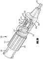
- the filament deployment mechanismcomprises an advancing hub, a spin collar, and a main hub.
- the advancing hubincludes a stem coupled to the plurality of filaments.
- the spin collarincludes a helical track.
- the stem of the advancing hubis at least partially inside the spin collar.
- the main hubcomprises a stem comprising a helical thread configured to cooperate with the helical track.
- the stem of the main hubis at least partially inside the spin collar.
- the stem of the advancing hubis at least partially inside the main hub.
- a needlecomprises an elongate member having a distal end, a tip coupled to the distal end of the elongate member, and a plurality of filaments.
- the tipcomprises a point.
- the plurality of filamentsis movable between a first position at least partially in the elongate member and a second position at least partially out of the elongate member.
- the plurality of filaments and the tipare configured to transmit radio frequency energy from a probe to operate as a monopolar electrode.
- a single wirecomprises the plurality of filaments.
- a needlecomprises an elongate member having a distal end, a tip coupled to the distal end of the elongate member, and a plurality of filaments.
- the tipcomprises a bevel to a point.
- the plurality of filamentsis movable between a first position at least partially in the elongate member and a second position at least partially out of the elongate member.
- the plurality of filaments and the tipare configured to transmit radio frequency energy from a probe to operate as a monopolar electrode.
- the tipcomprises a stem at least partially in the elongate member.
- the stemincludes a first filament lumen, a second filament lumen, and a third lumen.
- the bevel portioncomprises a fluid port in fluid communication with the third lumen.
- a needlecomprises an elongate member having a proximal end and a distal end, a tip coupled to the distal end of the elongate member, a plurality of filaments, and a rotational deployment mechanism coupled to the proximal end of the elongate member.
- the tipcomprises a bevel to a point.
- the plurality of filamentsis movable between a plurality of positions between at least partially in the elongate member and at least partially out of the elongate member.
- the deployment mechanismcomprises indicia of fractional deployment of the plurality of filaments relative to the tip.
- the plurality of filaments and the tipare configured to transmit radio frequency energy from a probe to operate as a monopolar electrode.
- a needlecomprises an elongate member having a distal end, a tip, and a plurality of filaments.
- the tipcomprises a first body portion and a second body portion.
- the first body portionincludes a tapered portion and a point.
- the tapered portionincludes a plurality of filament ports.
- the second body portionis coupled to the distal end of the tip.
- the second body portionis at an angle with respect to the first body portion.
- the plurality of filamentsis movable between a first position at least partially in at least one of the tip and the elongate member and a second position at least partially out of the filament ports.
- the plurality of filaments and the tipare configured to transmit radio frequency energy from a probe to operate as a monopolar electrode.
- a method of heating a vertebral disccomprises: positioning a distal end of a needle in a posterior annulus; deploying a filament out of the needle; traversing the posterior annulus from lateral to medial; applying radio frequency energy to the tip and to the filament; and ablating pain fibers in the posterior annulus.
- a needle for insertion into a patient during an RF ablation procedurecomprises a hub, an elongate member fixed to the hub, a tip fixed to the elongate member at a distal end of the needle, a plurality of filaments in at least a portion of the elongate member, an actuator interconnected to the plurality of filaments, and a lumen in the elongate member.
- the tipis shaped to pierce tissue of the patient. Movement of the actuator relative to the hub moves the plurality of filaments relative to the tip.
- the lumen and the tipare configured to accept an RF probe such that an electrode of an inserted RF probe, the tip, and the first and second filaments are operable to form a single monopolar RF electrode.
- a needle for insertion into a patient during an RF ablation procedurecomprises a hub, an elongate member fixed to the hub, a tip fixed to the elongate member at a distal end of the needle, a plurality of filaments in at least a portion of the elongate member in a retracted position, and an actuator interconnected to the plurality of filaments.
- the actuatoris operable to move the plurality of filaments relative to the hub, the elongate member, and the tip between the retracted position and a fully deployed position. In the fully deployed position, the plurality of filaments extends outwardly and away from the tip.
- Each filamentcomprises a distal end that defines a point in the fully deployed position. Each point is distal to the distal end of the needle. The average of all the points is offset from a central longitudinal axis of the elongate member.
- a needle for insertion into a patient during an RF ablation procedurecomprises a hub, an elongate member fixed to the hub, a tip fixed to the elongate member at a distal end of the needle, a plurality of filaments in at least a portion of the elongate member in a retracted position, and an actuator interconnected to the plurality of filaments.
- the actuatoris operable to move the plurality of filaments relative to the hub, the elongate member, and the tip between the retracted position and a deployed position. In the deployed position, the plurality of filaments extends outwardly and away from the tip.
- Each filamentcomprises a distal end that defines a point in the deployed position. Each point is distal to the distal end of the needle. Each point is on a common side of a plane that contains a central longitudinal axis of the elongate member.
- a needle for insertion into a patient during an RF ablation procedurecomprises a hub, an elongate member fixed to the hub, a tip fixed to the elongate member at a distal end of the needle, a plurality of filaments in at least a portion of the elongate member in a retracted position, and an actuator interconnected to the plurality of filaments.
- the plurality of filamentsconsists of a first filament and a second filament, and the needle contains no filaments other than the first and second filaments.
- the actuatoris operable to move the plurality of filaments relative to the hub, the elongate member, and the tip between the retracted position and a deployed position.
- the plurality of filamentsextends outwardly and away from the tip.
- Each filamentcomprises a distal end that defines a point in the deployed position. Each point is distal to the distal end of the needle.
- a midpoint between the distal end of the first filament and the distal end of the second filamentis offset from a central longitudinal axis of the needle.
- a needle for insertion into a patient during an RF ablation procedurecomprises a hub, an elongate member fixed to the hub, a tip fixed to the elongate member at a distal end of the needle, a plurality of filaments in at least a portion of the elongate member in a retracted position, and an actuator interconnected to the plurality of filaments.
- the plurality of filamentsconsists of a first filament and a second filament, and the needle contains no filaments other than the first and second filaments.
- the actuatoris operable to move the plurality of filaments relative to the hub, the elongate member, and the tip between the retracted position and a deployed position.
- each filamentIn the deployed position, the plurality of filaments extends outwardly and away from the tip.
- Each filamentcomprises a distal end that defines a point in the deployed position.
- Each pointis distal to the distal end of the needle.
- each distal enddefines a vertex of a polygon.
- a centroid of the polygonis offset from a central longitudinal axis of the needle.
- a needle for insertion into a patient during an RF ablation procedurecomprises a hub, an elongate member fixed to the hub, a tip fixed to the elongate member at a distal end of the needle, a plurality of filaments in at least a portion of the elongate member in a retracted position, and an actuator interconnected to the plurality of filaments.
- the plurality of filamentsconsists of a first filament and a second filament, and the needle contains no filaments other than the first and second filaments.
- the actuatoris operable to move the plurality of filaments relative to the hub, the elongate member, and the tip between the retracted position and a deployed position.
- each filamentIn the deployed position, the plurality of filaments extends outwardly and away from the tip. Each filament comprises a distal end that defines a point in the deployed position. Each point is distal to the distal end of the needle. In their respective deployed positions, each of the plurality of filaments points in an at least partially distal direction.
- a needle for insertion into a patient during an RF ablation procedurecomprises a hub, an elongate member fixed to the hub, a tip fixed to the elongate member at a distal end of the needle, a plurality of filaments in at least a portion of the elongate member in a retracted position, and an actuator interconnected to the plurality of filaments.
- the plurality of filamentsconsists of a first filament and a second filament, and the needle contains no filaments other than the first and second filaments.
- the actuatoris operable to move the plurality of filaments relative to the hub, the elongate member, and the tip between the retracted position and a deployed position.
- the plurality of filamentsIn the deployed position, the plurality of filaments extends outwardly and away from the tip. Each filament comprises a distal end that defines a point in the deployed position. Each point is distal to the distal end of the needle. When the plurality of filaments are in the deployed position, portions of each filament extend outwardly away from the tip. Each portion of each filament extending outwardly away from the tip is straight.
- a needle for insertion into a patient during an RF ablation procedurecomprises a hub, an elongate member fixed to the hub, a tip fixed to the elongate member at a distal end of the needle, a plurality of filaments in at least a portion of the elongate member in a retracted position, and an actuator interconnected to the plurality of filaments.
- the plurality of filamentsconsists of a first filament and a second filament, and the needle contains no filaments other than the first and second filaments.
- the actuatoris operable to move the plurality of filaments relative to the hub, the elongate member, and the tip between the retracted position and a deployed position.
- the plurality of filamentsIn the deployed position, the plurality of filaments extends outwardly and away from the tip. Each filament comprises a distal end that defines a point in the deployed position. Each point is distal to the distal end of the needle.
- the tipWhen the plurality of filaments is in the deployed position, the tip comprises an angle of at least 200° about the central longitudinal axis of the elongate member that is free of filaments.
- a method of performing spinal RF neurotomy in a patientcomprises moving a tip of a needle to a first position proximate to a target nerve along the spine of the patient, after achieving the first position, advancing a plurality of filaments relative to the tip to a deployed position, and after the advancing step, applying RF energy to the tip and plurality of filaments, wherein said applying generates heat that ablates a portion of the target nerve.
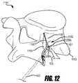
- a method of performing lumbar RF neurotomy on a medial branch nerve in a patientcomprises: moving a tip of a needle to a first position between the transverse and superior articular processes of a lumbar vertebra such that an end point of the tip is proximate to a surface of the vertebra; after achieving the first position, advancing a plurality of filaments relative to the tip to a deployed position; and after advancing the plurality of filaments, applying RF energy to the tip and the plurality of filaments. Said applying generates heat that ablates a portion of the medial branch nerve.
- a method of performing sacroiliac joint RF neurotomy in a patientcomprises: a. moving a tip of a needle to a first position proximate to a sacrum of the patient; b. advancing a plurality of filaments relative to the tip to a first deployed position; c. applying RF energy to the tip and plurality of filaments, wherein the applying generates heat that ablates a first volume; d. retracting the plurality of filaments; e. with the tip in the first position, rotating the needle about a central longitudinal axis of the needle to re-orient the plurality of filaments; f. re-advancing the plurality of filaments relative to the tip; and g.
- re-applying RF energy to the tip and plurality of filamentswherein the re-applying comprises ablating a second volume proximate to the tip, wherein a center of the first volume is offset from a center of the second volume.
- a method of performing thoracic RF neurotomy on a medial branch nerve in a patientcomprises: moving a tip of a needle to a first position proximate a superior surface of a transverse process of a thoracic vertebra such that an end point of the tip is proximate to the superior surface; after achieving the first position, advancing a plurality of filaments relative to the tip toward a vertebra immediately superior to the thoracic vertebra to a deployed position; and after advancing the plurality of filaments, applying RF energy to the tip and the plurality of filaments, wherein said applying generates heat that ablates a portion of the medial branch nerve between the thoracic vertebra and the vertebra immediately superior to the thoracic vertebra.
- a method of performing cervical medial branch RF neurotomy on a third occipital nerve of a patientcomprises: a. positioning the patient in a prone position; b. targeting a side of the C2/3 Z-joint; c. rotating the head of the patient away from the targeted side; d. locating the lateral aspect of the C2/3 Z-joint; e. moving, after steps a, b, c and d, a tip of a needle over the most lateral aspect of bone of the articular pillar at the juncture of the C2/3 z-joint to a first position contacting bone proximate to the most posterior and lateral aspect of the z-joint complex; f.
- step eretracting, after step e, the tip of the needle a predetermined distance from the first position; g. extending, after step f, a plurality of filaments outwardly from the tip and towards the lateral aspect of the C2/3 z-joint such that the plurality of filaments are positioned straddling the lateral joint lucency and posterior to the C2/3 neural foramen; h. verifying, after step g, the position of the tip and filaments by imaging the tip and a surrounding volume; and i. applying, after step h, RF energy to the tip and the plurality of filaments, wherein the applying generates heat that ablates a portion of the third occipital nerve.
- FIG. 1is a schematic diagram of an RF neurotomy system being used to perform RF neurotomy on a patient.
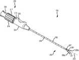
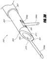
- FIG. 2Ais a perspective view of an example embodiment of a needle that may be used in an RF neurotomy procedure.
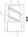
- FIG. 2Bis a cut away perspective view of a portion of the needle of FIG. 2A .
- FIG. 2Cis a partial cut away and partial cross-sectional view of a portion of another example embodiment of a needle that may be used in an RF neurotomy procedure.
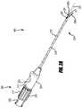
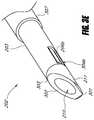
- FIG. 2Dis a perspective view of another example embodiment of a needle that may be used in an RF neurotomy procedure.
- FIG. 2Eis a perspective view of an example embodiment of filaments formed from a single wire.
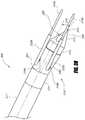
- FIG. 3Ais a detailed view of an example embodiment of a needle tip with filaments in a fully deployed position.
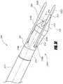
- FIG. 3Bis a detailed view of the needle tip of FIG. 3A with filaments in a retracted position.
- FIG. 3Cis a detailed view of another example embodiment of a needle tip with filaments in a deployed position.
- FIG. 3Dis a detailed view of another example embodiment of a needle tip with filaments in a fully deployed position.
- FIG. 3Eis a detailed view of the needle tip of FIG. 3D with filaments in a retracted position.
- FIG. 3Fis a cross-sectional view of the needle tip of FIG. 3D with filaments in a retracted position.
- FIG. 3Gis a detailed view of yet another example embodiment of a needle tip with filaments in a deployed position.
- FIGS. 3H and 3Iare detailed views of still other example embodiments of a needle tip with filaments in a deployed position.
- FIG. 4is a schematic diagram of an example embodiment of an RF probe assembly.
- FIG. 5is a proximal-facing end view of an example embodiment of a needle tip.
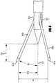
- FIG. 6is a side view of an example embodiment of a needle tip.
- FIG. 7is a proximal-facing end view of another example embodiment of a needle tip.
- FIG. 8is a proximal-facing end view of yet another example embodiment of a needle tip.
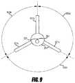
- FIG. 9is a proximal-facing end view of still another example embodiment of a needle tip.
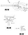
- FIG. 10is a side view of another example embodiment of a needle tip.
- FIG. 11Ais an illustration of an example set of isotherms that may be created with the needle of FIG. 2A .
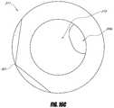
- FIG. 11Bis an illustration of an example lesion that may be created with the needle of FIG. 2A .
- FIG. 11Cis an illustration of an example lesion that may be created with a single-filament needle.
- FIG. 12is a perspective view of the needle of FIG. 2A positioned relative to a lumbar vertebra for performing RF neurotomy.
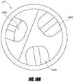
- FIG. 13is an illustration of a sacrum including target lesion volumes for performing Sacroiliac Joint (SIJ) RF neurotomy.
- SIJSacroiliac Joint
- FIG. 14is a perspective view of the needle of FIG. 2A positioned relative to a thoracic vertebra for performing RF neurotomy.
- FIG. 15is a perspective view of the needle of FIG. 2A positioned relative to the C2/3 cervical zygapophyseal joint (z-joint) for performing cervical medial branch RF neurotomy on the third occipital nerve.
- FIG. 16Ais a perspective view of an example embodiment of a needle tip.
- FIG. 16Bis a back elevational view of the needle tip of FIG. 16A .
- FIG. 16Cis a front elevational view of the needle tip of FIG. 16A .
- FIG. 16Dis a perspective view of an example embodiment of an elongate member.
- FIG. 16Eis a perspective view of the needle tip of FIG. 16A and the elongate member of FIG. 16D .
- FIG. 16Fis a cross-sectional view of the needle tip and elongate member of FIG. 16E along the line 16 F- 16 F of FIG. 16E and example embodiments of a filament and an RF probe.
- FIG. 16Gis a cross-sectional view of another example embodiment of a needle tip and elongate member and example embodiments of a filament and an RF probe.
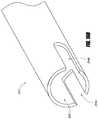
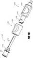
- FIG. 17Ais an exploded view of components of the deployment mechanism of FIG. 2D .
- FIG. 17Bis a cross-sectional view of components of the deployment mechanism of FIG. 2D .
- FIG. 17Cis a perspective view of an example embodiment of an advancing hub and the wire of FIG. 2E .
- FIG. 17Dis a cross-sectional view of an example embodiment of a spin collar.
- FIG. 17Eis a cross-sectional view of an example embodiment of a main hub, taken along the line 17 E- 17 E of FIG. 17B , in exploded view with an example embodiment of an elongate member.
- FIG. 18Ais an axial view of posterior oblique needle entry.
- FIG. 18Bis a sagittal view of posterior oblique needle entry.
- the inventionis set forth in the context of apparatuses and methods for performing RF ablation. More particularly, the systems and methods may be used to perform RF neurotomy to ablate portions of target nerves. Even more particularly, the systems and methods may be used to perform spinal RF neurotomy to ablate portions of target nerves along the spine of a patient to relieve pain.
- embodiments of methods and apparatuses described hereinrelate to lumbar RF neurotomy to denervate a facet joint between the L4 and L5 lumbar vertebrae.
- Denervationmay be achieved by application of RF energy to a portion of a medial branch nerve to ablate or cauterize a portion of the nerve, thus interrupting the ability of the nerve to transmit signals to the central nervous system.
- embodiments described hereinrelate to sacroiliac joint RF neurotomy.
- FIG. 1illustrates an example embodiment of a system 100 for performing RF neurotomy on a patient 101 .
- the patient 101may be positioned face down on a table or surface 109 to allow access along the spine of the patient 101 .
- Other patient orientationsare also possible depending on the procedure.
- the table 109may comprise radiolucent materials substantially transparent to x-rays, such as carbon fiber.
- the system 100may include an RF generator 102 capable of generating an RF energy signal sufficient to ablate target tissue (e.g.: cause lesions in targeted volumes; cauterize targeted portions of target nerves).
- the RF generator 102may, for example, be capable of delivering RF energy between about 1 W and about 200 W and between about 460,000 Hz and about 500,000 Hz.
- a needle 103 capable of conducting (e.g., transmitting or directing) RF energymay be interconnected to the RF generator 102 and may be used to deliver an RF energy signal to a specific site within the patient 101 .
- a return electrode pad 104may be attached to the patient 101 to complete a circuit from the RF generator 102 , through the needle 103 , through a portion of the patient 101 , through the return electrode pad 104 , and back to the RF generator 102 .
- the needle 103may comprise at least one supply electrode and at least one return electrode to define the circuit.
- the RF generator 102may be operable to control the RF energy emanating from the needle 103 in a closed-loop fashion.
- the needle 103 and/or an RF probe in the needle 103may include a temperature measurement device, such as a thermocouple, configured to measure temperature at the target tissue.
- Datamay also be available from the RF generator 102 , such as power level and/or impedance, which may also be used for closed-loop control of the needle 103 .
- a parametere.g., frequency, wattage, application duration
- FIG. 4illustrates an example RF probe assembly 400 compatible with the needle 103 .
- the RF probe assembly 400includes an RF probe 401 that may be inserted into a patient (e.g., through the needle 103 ) and may direct RF energy to the target tissue.
- the RF probe 401may be in electrical communication with the needle 103 to direct RF energy to the target tissue, but is not inserted into the patient.
- the RF probe 401may include a thermocouple operable to measure temperature at a distal end 402 of the RF probe 401 .
- the RF probe assembly 400may include a connector 403 and a cable 404 configured to connect the RF probe 401 to an RF generator (e.g., the RF generator 102 ).
- the system 100optionally includes an imaging system 105 capable of producing internal images of the patient 101 and the needle 103 , for example to facilitate navigation of the needle 103 during a procedure.
- the system 100may further include a display device for displaying the generated images to a user performing the procedure.
- the imaging system 105comprises a fluoroscope capable of generating real-time two dimensional images of the needle 103 and internal structures of the patient 101 .
- the imaging systemincludes an X-ray source 106 , an X-ray detector 107 , and a controller 108 in electrical communication with the X-ray source 106 and/or the X-ray detector 107 .
- the X-ray source 106 and X-ray detector 107may be mounted on a movable structure (e.g., a C-arm), to facilitate capturing a variety of images of the patient 101 (e.g., at various angles or projection views).
- a movable structuree.g., a C-arm
- Other imaging systems 105are also possible (e.g., a computed tomography (CT) scanner).
- CTcomputed tomography
- FIG. 2Aillustrates an example embodiment of a needle 103 that may be used in the system 100 for performing RF neurotomy.
- the needle 103includes a tip 201 that tapers to a point 301 capable of piercing the skin of a patient.
- the tip pointtapers to a point substantially at the center of the tip 201 (e.g., a “pencil-point” tip).
- the tip pointtapers to a point substantially at one side of the tip 201 (e.g., a “cutting” or “beveled” or “lancet” or “Quincke” tip).
- the needle 103further includes an elongate member 203 connected to the tip 201 at a distal end 202 of the needle 103 and connected to a hub 204 at a proximal end 205 of the needle 103 .
- the needle 103includes a longitudinal axis 223 along the center of the elongate member 203 .
- FIG. 2Dillustrates another example embodiment of a needle 103 that may be used in the system 100 for performing RF neurotomy.
- the needle 103includes a tip 211 that tapers to a point 301 capable of piercing the skin of a patient.
- the tip pointtapers to a point substantially at the center of the tip 211 (e.g., a “pencil-point” tip).
- the tip pointtapers to a point substantially at one side of the tip 211 (e.g., a “cutting” or “beveled” or “lancet” or “Quincke” tip).
- the needle 103further includes an elongate member 203 connected to the tip 211 at a distal end 202 of the needle 103 and connected to a hub 204 at a proximal end 205 of the needle 103 .
- the needle 103includes a longitudinal axis 223 along the center of the elongate member 203 .
- the needle 103may include a self-contained mechanical mechanism, in the form of deployable filaments 206 a , 206 b , operable to expand the volume of effective RF energy delivery as compared to known single-electrode RF probes.
- the filaments 206 a , 206 bmay be at least partially in the elongate member 203 and may be operable to emerge through one or more apertures of the needle 103 proximate to the distal end 202 of the needle 103 .
- the needle 103includes a single filament or three or more filaments.
- the filaments 206 a , 206 ballow contraction/expansion, offsetting, and/or contouring of the effective RF energy delivery over a selected area of anatomy to adjust lesion geometry produced using the needle 103 to match a desired target volume (e.g., spherical, hemispherical, planar, spheroid, kidney-shaped, catcher's mitt-shaped, oblong, snowman-shaped, etc.).
- the filaments 206 a , 206 bmay be deployable and/or retractable by moving (e.g., rotating) an actuator 216 relative to the hub 204 .
- the needle 103may further include a tube 207 that includes a lumen 222 therethrough.
- the lumen 222may be used to transport fluids to and/or from the target volume.
- the lumen 222may also accept the RF probe 401 for delivery of RF energy to the target volume.
- the lumen 222may also accept a dummy or temporary probe, for example to occlude the fluid port 210 during insertion.
- the RF probe 401is integrated with the needle 103 .
- the tube 207need not be present for RF energy delivery, although it may be included to facilitate fluid delivery.
- the filaments 206 a , 206 binclude lumens therethrough for the transportation of fluid to and/or from the target volume. In some embodiments, the filaments 206 a , 206 b do not include lumens therethrough (e.g., being solid). The filaments 206 a , 206 b may function as thermocouples.
- a needle 103 with deployable filaments 206 a , 206 bcan overcome this obstacle and expand the effective area of RF energy delivery by providing multiple locations (e.g., the tip 201 , 211 the filament 206 a , and/or the filament 206 b ) from which the RF energy emanates.
- the use of multiple filaments 206 a , 206 bprovides additional conduits for RF energy, creating a multiple electrode RF field effect.
- the size, shape, and location of a lesion created with the needle 103may be at least partially determined by, for example, the quantity, angle, length, location, and/or orientation of the filaments and RF energy parameters such as wattage, frequency, and/or application duration, one or all of which may be beneficially modified to suit a specific anatomical application by changing various aspects of the filaments as discussed below.
- the lesionmay be offset in a desired direction from the central longitudinal axis 223 by rotationally orienting the needle 103 .
- the needle 103may be used to create a lesion offset from the central longitudinal axis 223 in a first direction.
- the filaments 206 a , 206 bmay be retracted (e.g., after creating a first lesion), the needle 103 rotated, and the filaments 206 a , 206 b re-deployed to create a lesion offset from the central longitudinal axis 223 in a second direction (e.g., to create a second lesion).
- FIGS. 3A and 3Bare detailed views of an example embodiment of a distal end 202 of a needle 103 that includes a tip 201 .
- the tip 201may include a sharpened point 301 (e.g., tapering to a point substantially at the center of the tip 201 , a pencil-point tip) for piercing the skin of a patient and facilitating advancement through tissue.
- the tip 201may include a tapered portion 302 that transitions the tip 201 from the point 301 to a body portion 303 .
- the body portion 303is the portion of the tip 201 that is proximal to the tapered portion 302 .
- the body portion 303may be cylindrical as illustrated, or may be other appropriate shapes.
- the body portion 303may have a cross-section that coincides with (e.g., is coaxial with) the cross section of the elongate member 203 .
- FIGS. 3D and 3Eare detailed views of another example embodiment of a distal end 202 of a needle 103 that includes a tip 211 .
- the tip 211may include a sharpened point 301 (e.g., tapering to a point substantially at one side of the tip 201 , a cutting or beveled or lancet or Quincke tip) for piercing the skin of a patient and facilitating advancement through tissue.
- the tip 211may include a tapered portion 302 that transitions the tip 211 from the point 301 to a body portion 303 .
- the body portion 303is the portion of the tip 201 that is proximal to the tapered portion 302 .
- the body portion 303may be cylindrical as illustrated, or may be other appropriate shapes (e.g., as illustrated in FIG. 16A ).
- the body portion 303may have a cross-section that coincides with (e.g., is coaxial with) the cross section of the elongate member 203 .
- the tip 211has a bevel angle between about 10° and about 45°, between about 15° and about 35°, between about 20° and about 30° (e.g., about 25°), combinations thereof, and the like. Other bevel angles are also possible.
- the point 301has an angle between about 40° and about 120°, between about 70° and about 90°, between about 75° and about 85° (e.g., about 79°), combinations thereof, and the like. Other angles are also possible.
- the tip 201 , 211may act as an RF energy delivery element.
- the tip 201 , 211may comprise (e.g., be made from) a conductive material such as, for example, stainless steel (e.g., 300 Series Stainless Steel).
- the tip 201 , 211may be at least partially coated (e.g., with an insulator).
- the material of the tip 201 , 211 and the material of the optional coatingmay be selected, for example, to act as an insulator, improve radiopacity, improve and/or alter RF energy conduction, improve lubricity, and/or reduce tissue adhesion.
- the tip 201 , 211includes a first filament port or slot 304 a (not visible in the views of FIGS. 3A, 3B, 3D, and 3E ) and a second filament port or slot 304 b .
- the geometry of the filament slots 304 a , 304 bmay be selected to allow filaments 206 a , 206 b to be adequately retracted (e.g., such that the filaments 206 a , 206 b are in a cross-sectional envelope of the body portion 303 of the tip 201 , 211 , as shown in FIG. 3F ) while the needle 103 is inserted into the body, so that the filaments 206 a , 206 b do not cause any unintended damage to the patient.
- Such positioning of the filament slots 304 a , 304 bavoids having filament exit features on the tapered portion 302 and thus avoids potential coring that could be caused by such positioning.
- the internal geometry of the filament slots 304 a , 304 bmay be designed such that the filaments 206 a , 206 b may be easily retracted and advanced.
- the internal geometry of the filament slots 304 a , 304 bmay include a transition region 305 that meets the outer surface of the body portion 303 at an angle of about 30°.
- the transition region 305may, for example, be curved and/or planar.
- Advancement of filaments 206 a , 206 b without a pre-set bias (e.g., substantially straight) relative to the filament slots 304 a , 304 bcan causes the filaments 206 a , 206 b to be deflected outwardly as the filaments 206 a , 206 b move distally along the transition region 305 .
- a pre-set biase.g., substantially straight
- the filaments 206 a , 206 bare confined to only longitudinal movement where they enter into the elongate member 203 ) and on the mechanical properties of the filaments 206 a , 206 b , various deployment angles of the filaments 206 a , 206 b relative to the central longitudinal axis 223 may be achieved.
- the portions of the filaments 206 a , 206 b that extend outwardly away from the filament slots 304 a , 304 bmay be unrestrained and thus may take any appropriate form.
- the portions of the filaments that extend outwardly away from the filament slots 304 a , 304 bmay be substantially straight, such as shown in FIGS. 2A, 3A, 3C, 3D, 6, 11A-11C , and 14 .
- the portions of the filaments that extend outwardly away from the filament slotsmay take any appropriate shape, such as, for example, curved as shown in FIG. 10 .
- the radial orientation of the filament slots 304 a , 304 bmay be selected such that a center point between the filament slots 304 a , 304 b does not coincide (e.g., is not coaxial with) with the central longitudinal axis 223 .
- the filament slots 304 a , 304 bmay be positioned such that they are about 120° apart about the circumference of the tip 201 , 211 .
- Other filament slot configurationsmay be configured to achieve the filament placements discussed below.
- the filament slots 304 a , 304 bmay be between about 45° and about 180° apart about the circumference of the tip 201 , 211 , between about 90° and about 180° apart about the circumference of the tip 201 , 211 , between about 90° and about 150° apart about the circumference of the tip 201 , 211 , combinations thereof, and the like. Other angles are also possible. These configurations may be achieved by varying, for example, the quantity of filament slots, the placement of filament slots about the circumference of the tip 201 , 211 , and/or the placement of filament slots along the center longitudinal axis 223 to achieve the filament placements discussed below.
- the needle 103may comprise a tube 207 that includes a lumen 222 therethrough.
- the lumen 222may be employed to accept the RF probe 401 for delivery of RF energy, for the transport of fluids, and/or for occluding a fluid port 210 .
- the tip 201 , 211may include a fluid port 210 that may be in fluid communication with the lumen 222 via a channel through the tip 201 , 211 .
- the lumen 222is a dual-purpose lumen that can allow injection of fluids and that can receive the distal end 402 of the RF probe 401 to deliver RF energy to the tip 201 , 211 , the filament 206 a , and/or the filament 206 b .
- the fluid port 210is longitudinally spaced from the tip 301 (e.g., by between about 1 mm and about 3 mm).
- the fluid port 210may be centrally located (e.g., as illustrated in FIG. 3D ) or it may be located offset from the center longitudinal axis 223 (e.g., as shown in FIGS. 2A and 3A ).
- the fluid port 210may be used to transfer fluid between the region of the tip 201 , 211 and the proximal end 205 of the needle 103 .
- an anesthetic and/or an image enhancing dyemay be introduced into the region of tissue around the tip 201 , 211 through the fluid port 210 .
- the fluid port 210is located along the tapered portion 302 of the tip 201 , 211 (e.g., as illustrated in FIGS. 3A and 3D ).
- the fluid port 210is located along the body portion 303 of the tip 201 , 211 .
- FIG. 16Ais a perspective view of an example embodiment of the needle tip 211 .
- the needle 103does not comprise a tube 207 , but the elongate member 203 comprises a lumen 308 therethrough and the tip 211 comprises a lumen 306 c therethrough.
- the lumen 308 and the lumen 306 cmay be employed to accept the RF probe 401 for delivery of RF energy, for the transport of fluids, and or for occluding the fluid port 210 .
- the lumen 308 and the lumen 306 care dual-purpose lumens that can allow injection of fluids and that can receive the distal end 402 of the RF probe 401 to deliver RF energy to the tip 211 , the filament 206 a , and/or the filament 206 b .
- the filament lumens 306 a , 306 bmay also allow liquid transfer from a proximal end of the needle to the filament ports 304 a , 304 b.
- the filament lumens 306 a , 306 bare sized to inhibit buckling and/or bending of the filaments in the tip 211 .
- the elongate member 203may also include filament lumens (e.g., comprising tubes in the elongate member 203 ).
- filament lumens in the elongate member 203may be formed by an inner member (not shown) extending at least part of the length of the elongate member 203 .
- a transverse cross-section of the inner membermay have the same cross-section as the portion of the tip 211 illustrated in FIG. 3F , including channels in which the filaments may lie and a lumen for passing fluid, an RF probe 401 , and/or a dummy probe.
- FIG. 16Bis a back elevational view of the needle tip 211 of FIG. 16A .
- FIG. 16Cis a front elevational view of the needle tip 211 of FIG. 16A .
- the needle tip 211comprises a filament lumen 306 a in fluid communication with and terminating at the filament slot 304 a , a filament lumen 306 b in fluid communication with and terminating at the filament slot 304 b , and the lumen 306 c .
- the lumens 306 a , 306 bare spaced by about 120° along the circumference of the tip 211 . Other angles are also possible.
- the lumen 306 cis spaced from each of the lumens 306 a , 306 b by about 120° along the circumference of the tip 211 . Other angles are also possible.
- the filament 206 amay be in the filament lumen 306 a and the filament 206 b may be in the filament lumen 306 b .
- the lumen 306 cis in fluid communication with the fluid port 210 .
- the proximal end of the tip 211includes a tapered surface, as shown in FIG. 16A .
- the tapered surfacemay help to guide insertion of an RF probe 401 into the lumen 306 c .
- the tapered surfacehas an angle normal to the tip 211 between about 15° and about 75°, between about 30° and about 60°, between about 40° and about 50° (e.g., about 45°), combinations thereof, and the like. Other angles are also possible.
- FIG. 16Dis a perspective view of an example embodiment of an elongate member 203 .
- the elongate member 203includes the lumen 308 , the filament slot 304 a , and the filament slot 304 b .
- the filament slots 304 a , 304 bare spaced by about 120° along the circumference of the elongate member 203 .
- FIG. 16Eis a perspective view of the needle tip 211 of FIG. 16A and the elongate member 203 of FIG. 16D .
- the elongate member 203may be coupled to the tip 211 by adhering with conductive epoxy, welding, soldering, combinations thereof, and the like.
- a proximal portion of the tip 211can be inserted into the lumen 308 of the elongate member 203 .
- the filament slot 304 b of the elongate member 203is substantially aligned with the lumen 306 b of the tip 211 , allowing the filament 206 b to be deployed out of the lumen 306 b .
- the filament slot 304 a of the elongate member 203is substantially aligned with the lumen 306 a of the tip 211 , allowing the filament 206 a to be deployed out of the lumen 306 a .
- each of the filament slots 304 a , 304 bhas a length between about 0.025 inches and about 0.2 inches (approx.
- each of the filament slots 304 a , 304 bhas a width between about 0.01 inches and about 0.4 inches (approx. between about 0.25 mm and about 10 mm), between about 0.02 inches and about 0.03 inches (approx.
- the each of the transition regions 305has a length between about 0.02 inches and about 0.2 inches (approx. between about 0.5 mm and about 5 mm), between about 0.05 inches and about 0.15 inches (approx. between about 1.3 mm and about 3.8 mm), between about 0.075 inches and about 0.125 inches (approx. between about 1.9 mm and about 3.2 mm) (e.g., about 0.104 inches (approx.
- the each of the transition regions 305has a radius of curvature between about 0.01 inches and about 0.4 inches (approx. between about 0.25 mm and about 10 mm), between about 0.15 inches and about 0.35 inches (approx. between about 3.8 mm and about 8.9 mm), between about 0.2 inches and about 0.3 inches (approx. between about 5 mm and about 7.6 mm) (e.g., about 0.25 inches (approx. about 6.4 mm)), combinations thereof, and the like. Other radii of curvature are also possible. Certain combinations of dimensions of the transition regions 305 and filaments slots 304 a , 304 b described herein may cause deployment of the filaments 206 a , 206 b at desired angles (e.g., about 30°).
- the lumen 308is not visible in FIG. 16E because the elongate member 203 covers the lumen 308 . Covering the lumen 308 causes fluid inserted into the lumen 308 to exit the fluid port 210 , and possibly the filament slots 304 a , 304 b .
- the elongate member 203may also include a slot proximate to the tube 207 .
- the tube 207may extend distal to the slot and substantially all fluid inserted into the lumen 222 exits the fluid port 210 .
- the body portion 303 of the tip 211 and the elongate member 203excluding the sleeve 307 , have substantially equal diameters, for example to provide a smooth transition between the tip 211 and the elongate member 203 .
- the elongate member 203has an inner diameter between about 0.01 inches and about 0.04 inches (approx. between about 0.25 mm and about 1 mm), between about 0.015 inches and about 0.035 inches (approx. between about 0.38 mm and about 0.89 mm), between about 0.02 inches and about 0.03 inches (approx. between about 0.5 mm and about 0.76 mm) (e.g., about 0.025 inches (approx.
- the elongate member 203has an outer diameter between about 0.01 inches and about 0.05 inches (approx. between about 0.25 mm and about 1.3 mm), between about 0.02 inches and about 0.04 inches (approx. between about 0.5 mm and about 1 mm), between about 0.025 inches and about 0.035 inches (approx. between about 0.64 mm and about 0.89 mm) (e.g., about 0.029 inches (approx. about 0.74 mm)), combinations thereof, and the like. Other diameters are also possible.
- the proximal portion of the tiphas an outer diameter between about 0.01 inches and about 0.04 inches (approx.
- the tip 211has an outer diameter between about 0.01 inches and about 0.05 inches (approx. between about 0.25 mm and about 1.3 mm), between about 0.02 inches and about 0.04 inches (approx. between about 0.5 mm and about 1 mm), between about 0.025 inches and about 0.035 inches (approx. between about 0.64 mm and about 0.89 mm) (e.g., about 0.029 inches (approx. about 0.74 mm)), combinations thereof, and the like. Other diameters are also possible.
- FIG. 16Fis a cross-sectional view of the needle tip 211 and the elongate member 203 along the line 16 F- 16 F of FIG. 16E .
- FIG. 16Falso illustrates an example embodiment of a filament 206 a in the lumen 308 and the lumen 306 a , then exiting via the filament slot 304 a , and an RF probe 401 in the lumen 308 .
- the elongate member 203 and the tip each 211comprise (e.g., are each made from) a conductive material (e.g., 300 Series Stainless Steel), and can conduct electrical signals from the RF probe 401 to the tip 211 and the filaments 206 a , 206 b (e.g., due to physical contact of conductive components) to form a monopolar electrode.
- the RF probe 401 , the filaments 206 a , 206 b , the tip 211 , and/or the elongate member 203may include features configured to increase physical contact between the components.
- the cross-sectional viewshows the lumen 308 in fluid communication with the lumen 306 c and the fluid port 210 .
- FIG. 16Gis another cross-sectional view of an example embodiment of a needle tip 211 and the elongate member 203 along a line similar to the line 16 F- 16 F in FIG. 16E .
- the tip 211 in FIG. 16Gdoes not include a fluid port 210 , but fluid can permeate out of the filament slots 304 a , 304 b because the filament slots are in fluid communication with the lumen 308 .
- the tip 211includes a lumen 306 c , for example to assure placement of or contact with the probe 401 (e.g., as illustrated in FIG. 16G ).
- the tip 211does not include a lumen 306 c , for example to reduce manufacturing costs if the lumen 306 c is cut from a solid tip stem.
- the channel through the tip 201 , 211may be sized to accommodate a tip of the RF probe 401 that may be inserted into the needle 103 .
- the channelmay be sized such that RF energy from the inserted RF probe 401 is satisfactorily communicated from the RF probe 401 to the tip 201 , 211 , the filament 206 a , and/or the filament 206 b.
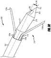
- FIGS. 3C and 3Gare each a detailed view of the distal end 310 of a needle 309 that is an alternate embodiment of the needle 103 .
- the distal end 310includes a tip 311 , 321 that may include a sharpened point 312 for piercing the skin of a patient and facilitating advancement through tissue.
- the tip 311 , 321may include a tapered portion 313 that transitions the tip 311 , 321 from the point 312 to a first body portion 314 .
- the first body portion 314may be connected to a second body portion 315 at an angle 316 . In some embodiments, the angle 316 is about 15°. Other angles 316 are also possible.
- the angle 316may be between about 5° and about 90°, between about 10° and about 60°, between about 10° and about 45°, between about 10° and about 20°, combinations thereof, and the like. Other angles are also possible.
- the second body portion 315may be aligned with an elongate member 317 .
- the elongate member 317may be similarly configured as the elongate member 203 of FIGS. 3A, 3B, 3C, and 3D .
- the angle 316 between the first body portion 314 and the second body portion 315may aid the user in navigating the needle 309 to a desired position. For example, by rotating the needle 309 such that the first body portion 314 is pointing in a desired direction, subsequent advancement of the needle 309 may result in the needle 309 following a non-straight path biased toward the desired direction.
- the first and second body portions 314 , 315may be cylindrical as illustrated, or they may be of any other appropriate shape.
- the first and second body portions 314 , 315may have cross-sections that coincide with (e.g., is coaxial with) the cross section of the elongate member 317 .
- the tip 311 , 321may act as an RF energy delivery element.
- the tip 311 , 321may comprise (e.g., be made from) a conductive material such as, for example, stainless steel (e.g., 300 Series Stainless Steel).
- the tip 311 , 321may be coated (e.g., with an insulator).
- the material of the tip 311 , 321 and the material of the optional coatingmay be selected, for example, to act as an insulator, improve radiopacity, improve and/or alter RF energy conduction, improve lubricity, and/or reduce tissue adhesion.
- the filaments 319 a , 319 bmay also act as RF energy delivery elements.
- the filaments 319 a , 319 bmay be constructed in a manner similar to as described with respect to the filaments 206 a , 206 b.
- the tip 311 of FIG. 3Cincludes a filament slot 318 a and a filament slot 318 b .
- the geometry of the filament slots 318 a , 318 bmay be selected to allow filaments 319 a , 319 b to be adequately retracted (e.g., such that they are in a cross-sectional envelope of the second body portion 315 ) while the needle 309 is inserted into the body, so that the filaments 319 a , 319 b do not cause any unintended damage to the patient (e.g., by being along the second body portion 315 ).
- Such positioning of the filament slots 318 a , 318 bmay avoid having filament exit features on the tapered portion 313 and on the first body portion 314 , which may avoid potential coring.
- the internal geometry of the filament slots 318 a , 318 bmay include a transition region that meets the outer surface of the second body portion 315 at an angle, and advancement of filaments 319 a , 319 b without a pre-set bias (e.g., substantially straight) relative to the filament slots 318 a , 318 b can causes the filaments 319 a , 319 b to be deflected outwardly as the filaments 319 a , 319 b move distally along the transition region.
- a pre-set biase.g., substantially straight
- the configuration and orientation of the filament slots 318 a , 318 bmay be selected such that deployed filaments 319 a , 319 b may achieve the positioning illustrated in FIG. 3C .
- the filaments 319 a , 319 bare generally positioned in a plane that is perpendicular to a plane that includes the angle 316 between the first and second body portions 314 , 315 .
- the filaments 319 a , 319 bmay be positioned such that they extend at an angle (e.g., about 15°, between about 10° and about 90°, between about 10° and about 60°, between about 10° and about 45°, between about 10° and about 20°, combinations thereof, and the like) relative to the plane that includes the angle 316 .
- an anglee.g., about 15°, between about 10° and about 90°, between about 10° and about 60°, between about 10° and about 45°, between about 10° and about 20°, combinations thereof, and the like
- Other anglesare also possible.
- Other filament slot 318 a , 318 b configurationsmay be configured to achieve other desired filament 319 a , 319 b placements.
- These configurationsmay be achieved, for example, by varying the quantity of filament slots and filaments, the placement of filament slots about the circumference of the tip 311 , the angle at which the filaments extend away from the first and second body portions 314 , 315 , and/or the placement of filament slots along the first and second body portions 314 , 315 .
- FIG. 3Gillustrates an example embodiment of a tip 321 that includes a filament slot 318 a and a filament slot 318 b along the first body portion 314 .
- the geometry of the filament slots 318 a , 318 bmay be selected to allow filaments 319 a , 319 b to be adequately retracted (e.g., such that they are in a cross-sectional envelope of the second body portion 315 ) while the needle 309 is inserted into the body, so that the filaments 319 a , 319 b do not cause any unintended damage to the patient.
- Positioning of the filament slots 318 a , 318 b along the first body portion 314may potentially cause coring, so the filaments 319 a , 319 b may be configured to substantially occlude the filament slots 318 a , 318 b , which may avoid potential coring.
- the internal geometry of the filament slots 318 a , 319 bmay lack a transition region and, due to being positioned on the first body portion 314 , advancement of the filaments 319 a , 319 b without a pre-set bias (e.g., substantially straight) can cause the filaments 319 a , 319 b to continue to advance substantially straight (e.g., along the longitudinal axis of the elongate member 317 and/or the second body portion 315 ) as the filaments move distally out of the filament slots 318 a , 318 b .
- a pre-set biase.g., substantially straight
- filament slotsalong the tapered portion 313 is also possible (e.g., the filaments continuing to advance along the longitudinal axis of the first body portion 314 ).
- the embodiments depicted in FIGS. 3A and 3Dmay be adapted so the filaments 206 a , 206 b exit along the tapered portion 302 .
- the needle 309may comprise a tube that includes a lumen therethrough, for example as described herein with respect to FIGS. 3A, 3B, 3D, and 3E .
- the lumenmay be employed to accept an RF probe for delivery of RF energy and/or for the transport of fluids.
- the tip 311may further include a fluid port 320 that may be in fluid communication via a channel through the tip 311 with the lumen.
- the fluid port 320may be used to transfer fluid between the region of the tip 311 and a proximal end of the needle 309 .
- the distal ends of the filaments 319 a , 319 bare disposed away from the point 312 .
- the distal ends of the filaments 319 a , 319 bare disposed away from the point 312 .
- the distal ends of the filaments 319 a , 319 bare entirely within an outer perimeter (e.g., circumference where the second body portion 315 of the tip 311 , 321 is round) of the tip 311 , 321 .
- the filaments 319 a , 319 bact as broadcast antennae for an RF probe inserted into the needle 309 .
- the tip 311 or 321 , the filament 319 a , and/or the filament 319 bmay form a monopolar electrode for application of RF energy to the target volume.
- the filaments 319 a , 319 bmay allow the RF energy from the RF probe to be dispersed over a larger volume than would be possible with the tip 311 , 321 alone.
- any or all of the herein variablesmay be incorporated into a particular embodiment of a needle to yield a needle capable of producing a lesion with a particular size, position and shape relative to the tip of the needle.
- Such custom sizes, positions and shapesmay be designed for specific procedures.
- a particular lesion size, position and shapemay be selected to enable a user to navigate the needle to a particular landmark (e.g., proximate to or touching a bone visible using fluoroscopy) and then orient the needle such that deployed filaments will be operable to produce a lesion at a particular location relative to the landmark.
- the lesion shapes achievable through selection of the herein variablesmay include, for example, generally spherical, oblong, conical, and pyramidal shapes.
- the orientation relative to, and the amount of offset from, the tip of such shapesmay be selectable.
- the tips of the deployed filamentsmay be positioned distally relative to the point of the tip to provide for a facile positioning of the lesion relative to the tip. Such capability may allow for the needle to be inserted directly toward a target volume.
- the tips of the deployed filamentsmay be positioned at the same axial position along the central longitudinal axis as the point of the tip or the tips of the deployed filaments may be positioned proximally relative to the point of the tip.
- some filament endpointsmay be located distal to the point of the tip while others are proximal to the point of the tip.
- the elongate member 203may be in the form of a hollow tube (e.g., sheath, cannula) interconnecting the tip 201 , 211 with the hub 204 .
- the elongate member 203may be configured with adequate strength to allow the needle 103 to pierce a patient's skin and advance to a target area through various tissue types, including, for example, fat and muscle tissue.
- the elongate member 203may also be capable of resisting kinking as it is advanced.
- the elongate member 203comprises a rod with a plurality of lumens along its length to accommodate the filaments 206 a , 206 b , the RF probe 401 , and/or a fluid passage.
- the elongate member 203houses portions of the filaments 206 a , 206 b and the tube 207 , and allows for relative movement of the filaments 206 a , 206 b .
- the elongate member 203may be of any appropriate size and internal configuration to allow insertion into a patient and to house componentry therein.
- the elongate member 203is a 16 gauge round tube or smaller.
- the elongate member 203may be 18 gauge or 20 gauge.
- the elongate member 203has a maximum cross-sectional dimension of about 1.7 mm.
- the elongate member 203has a maximum cross-sectional dimension of about 1 mm.
- the elongate member 203may have a length selected for performing a specific spinal RF neurotomy procedure on a particular patient. In some embodiments, the elongate member 203 has a length of about 10 cm.
- the elongate member 203comprises (e.g., is constructed from) an insulative material to reduce (e.g., eliminate) the amount of RF energy emitted along the length of the elongate member 203 when the RF probe 401 is disposed therein.
- the elongate member 203may comprise (e.g., be constructed from) polymeric, ceramic, and/or other insulative material.
- the elongate member 203includes an insulating coating or sleeve 307 ( FIGS. 2D and 16D ).
- the elongate memberis insulated (e.g., constructed from insulative material and/or having an insulating coating 307 ) except for a distal part having a length between about 5 mm and about 10 mm.
- FIG. 3Hillustrates an example embodiment of a needle 309 comprising an insulating coating 330 covering a proximal portion of the tip 321 and coatings 332 a , 332 b covering a proximal portion of the filaments 319 a , 319 b .
- the coating 330insulates, inter alia, the bent area between the first body portion 314 and the second body portion 315 of the tip 321 .
- the elongate memberis insulated (e.g., constructed from insulative material and/or having an insulating coating) except for a proximal part.
- FIG. 3Iillustrates an example embodiment of a needle 309 comprising an insulating coating 330 covering a distal portion of the tip 321 and coatings 332 a , 332 b covering a distal portion of the filaments 319 a , 319 b .
- the needle 309may create a kidney or catcher's mitt shaped lesion, which may be useful, for example, for ablating tissue where the active tip is pressed against the wall of a structure with the device staying in the lumen of a structure.
- insulating the distal portion of the tip 321which stays in the chamber, can make the biophysics of the lesion (e.g., impedance, power, heat) more precise because the insulated distal portion of the tip 321 that is surrounded by blood in the chamber will not be part of the field.
- FIGS. 3H and 3Iillustrate example embodiments of insulation of parts of the tip 321 and the filaments 319 a , 319 b illustrated in FIG. 3G .
- Parts of components of the distal ends of other needle tips described hereinmay also be insulated (e.g., those illustrated in FIGS. 3A, 3C, and 3D ).
- only parts of the tip 321 , and not parts of the filaments 319 a , 319 bare insulated.
- only parts of the filaments 319 a , 319 b , and not parts of the tip 321are insulated.
- a distal portion of the tip 321is insulated (e.g., as illustrated in FIG.
- proximal portions of the filaments 319 a , 319 bare insulated (e.g., as illustrated in FIG. 3H ).
- a distal portion of the filaments 319 a , 319 bare insulated (e.g., as illustrated in FIG. 3I ) and a proximal portion of the tip 321 is insulated (e.g., as illustrated in FIG. 3H ).
- the insulative coating or sleeve 330 , 332 a , 332 bmay be adjustable.
- one or all of the sleeves 330 , 332 a , 332 bmay be advanced or retracted relative to the tip 321 , the filament 319 a , and the filament 319 b , respectively, to increase or decrease the amount of exposed conductive area.
- the elongate member 203may include a coating that may improve radiopacity to aid in visualization of the position of the needle 103 using fluoroscopy.
- the elongate member 203may include a lubricious coating to improve its ability to be inserted and positioned in the patient and/or to reduce tissue adhesion.
- the elongate member 203may include markers 224 along its length to assist in determining the depth to which the needle 103 has entered into the anatomy.
- the markers 224may be radiopaque so that they may be viewed under fluoroscopy.
- a collar(not shown) may be disposed about the elongate member 203 to assist in placement of the tip 201 , 211 of the needle 103 .
- the tip 201 , 211may be positioned in a first position, the collar may then be placed against the patient's skin, and then the needle 103 may be advanced and/or withdrawn a certain distance. Such a distance may be indicated, for example, by the distance between the collar and a patient's skin or other anatomy.
- the elongate member 203may be fixedly interconnected to the tip 201 , 211 and the hub 204 in any appropriate manner.
- the tip 201 , 211may be press fit into the elongate member 203 and the elongate member 203 may be press fit into the hub 204 .
- Other example methods of attachmentinclude adhesive bonding and welding.
- the elongate member 203 and the tip 201 , 211are a single unitary structure.
- the elongate member 203may be steerable and incorporate controlling mechanisms allowing the elongate member 203 to be deflected or steered after insertion into the anatomy.
- the tube 207 containing the lumen 222may comprise (e.g., be constructed from) any appropriate material.
- the tube 207comprise a conductive material, such as stainless steel (e.g., 300 Series Stainless Steel), such that when the RF probe 401 is inserted in the tube 207 , the RF energy emitted by the RF probe 401 may be conducted through the tube 207 and into and through the tip 201 , 211 , the filament 206 a , and/or the filament 206 b .
- the tube 207may be interconnected to the tip 201 , 211 such that the lumen 222 is in sealed, fluid communication with the channel through the tip 201 , 211 . This may be accomplished by a press fit, weld, or any other appropriate method.
- the lumen 222may be in fluid communication with the tip 201 , 211 at the distal end 202 .
- a proximal end of the lumen 222may be disposed at the proximal end 205 of the needle 103 .
- the lumen 222may extend from the distal end 202 to the proximal end 205 , with the only access being at the distal and proximal ends 202 , 205 .
- the lumen 222is the only lumen of the needle 103 disposed along the elongate member 203 .
- the RF probe 401 inserted into the lumen 222may be positioned such that an end of the RF probe 401 is proximate to the tip 201 , 211 .
- the RF probe 401may be positioned such that the distal end 402 of the RF probe 401 is in the lumen 222 near the tip 201 , 211 or in the channel through the tip 201 , 211 .
- RF energy transmitted through the RF probe 401may then be conducted by the tip 201 , 211 , the filament 206 a , and/or the filament 206 b .
- the size of the lumen 222may be selected to accommodate a particular size of RF probe 401 .
- the lumen 222may be configured to accommodate at least a 22 gauge RF probe 401 , at least a 21 gauge RF probe 401 , or a larger or smaller RF probe 401 .
- the lumen 222may have a maximum cross-sectional dimension of less than about 0.85 mm.
- the proximal end of the tube 207may be operable to receive the RF probe 401 .
- the proximal end of the tube 207 and the actuator 216may be configured to accept a connector, such as a Luer fitting, such that a fluid source may be connected to the tube 207 (e.g., to deliver fluid through the lumen 222 and out the fluid port 210 ).
- the needle 103includes two filaments 206 a , 206 b in and along elongate member 203 . Distal ends of the filaments 206 a , 206 b are proximate to the tip 201 , 211 , and proximal ends of the filaments 206 a , 206 b are fixed to a filament hub 221 discussed below.
- the filaments 206 a , 206 bare movable along the central longitudinal axis 223 between a fully deployed position as illustrated in FIGS. 3A, 3C, 3D, and 3F and a retracted position illustrated in FIGS. 3B and 3E .
- the filaments 206 a , 206 bmay be deployed in intermediate positions between the fully deployed positions and the retracted positions.
- a mechanism for advancement and/or retraction of the filaments 206 a , 206 bmay include detents indicating partial deployment and/or retraction and a stop indicating full deployment and/or retraction.
- the distal ends of the filaments 206 a , 206 b , 319 a , 319 bare disposed away from the tip 201 , 211 , 311 , 321 .
- the distal ends of the filaments 206 a , 206 b , 319 a , 319 bare entirely within an outer perimeter (e.g., circumference where the body portion 303 of the tip 201 , 211 , 311 , 321 is round) of the tip 201 , 211 , 311 , 321 .
- the filaments 206 a , 206 b , 319 a , 319 bcan act as broadcast antennae for the RF probe 401 (e.g., RF energy passes from the RF probe 401 to the tip 201 , 211 , 311 , 321 and to the filaments 206 a , 206 b , 319 a , 319 b , and into a target volume within a patient).
- RF energypasses from the RF probe 401 to the tip 201 , 211 , 311 , 321 and to the filaments 206 a , 206 b , 319 a , 319 b , and into a target volume within a patient.
- the RF probe 401 inserted into the lumen 222 , the tip 201 , 211 , 311 , 321 , and the filaments 206 a , 206 b , 319 a , 319 bmay form a monopolar electrode for application of RF energy to the target volume.
- the filaments 206 a , 206 b , 319 a , 319 ballow the RF energy from the RF probe 401 to be dispersed over a larger volume than would be possible with the tip 201 , 211 , 311 , 321 alone.
- the filaments 206 a , 206 b , 319 a , 319 bmay be constructed from a material operable to conduct RF energy, e.g., a metal such as stainless steel (e.g., 303 Stainless Steel), Nitinol, or shape memory alloy.
- the filaments 206 a , 206 bmay be coated, for example to enhance and/or inhibit their ability to conduct RF energy.
- the filaments 206 a , 206 bmay include a lubricious coating to aid in insertion and/or reduce tissue adhesion.
- FIG. 2Eillustrates an embodiment in which the filaments 206 a , 206 b are formed from a single wire 206 that is bent at the proximal end.
- the distal ends of the filaments 206 a , 206 bare shown as bent, which can be the result of deflection upon exit from a tip 201 , 211 , shape memory, combinations thereof, and the like.
- Forming the filaments 206 a , 206 b from a single wire 206may provide advantages such as, for example, coherent activation of the filaments 206 a , 206 b , simultaneous deployment of the filaments 206 a , 206 b , and/or simultaneous retraction of the filaments 206 a , 206 b .
- the wire 206may be a single wire or a plurality of wire segments joined together (e.g., via adhering with conductive epoxy, welding, soldering, combinations thereof, and the like).
- Other filaments described hereinmay also be coupled or bent at the proximal end.
- the filaments 206 a , 206 b illustrated in FIG. 2Eare substantially parallel, and taper outwards before being bent at the proximal end. In some embodiments, the filaments 206 a , 206 b are substantially parallel and do not taper out before being bent at the proximal end.
- the proximal end of the wire 206is a semi-circle, for example having a radius between about 0.03 inches and about 0.07 inches (approx. between about 0.76 mm and about 1.8 mm), between about 0.04 inches and about 0.06 inches (approx. between about 1 mm and about 1.5 mm), between about 0.05 inches and about 0.055 inches (approx. between about 1.3 mm and about 1.4 mm) (e.g., about 0.052 inches (approx. about 1.32 mm)), combinations thereof, and the like.
- the filaments 206 a , 206 bare parallel and spaced by a distance between about 0.025 inches and about 0.125 inches (approx.
- the filaments 206 a , 206 b in the elongate member 203may be braided, wrapped, or twisted together. Such embodiments may increase column strength, providing resistance to buckling and/or bending in the elongate member 203 .
- the wire 206has a diameter between about 0.0025 inches and about 0.04 inches (approx.
- the filaments 206 a , 206 beach have a diameter between about 0.0025 inches and about 0.04 inches (approx. between about 0.06 mm and about 1 mm), between about 0.005 inches and about 0.025 inches (approx.
- the filaments 206 a , 206have different diameters (e.g., by being formed from different wires, by being formed from portions of wires with different diameters that are coupled to form the wire 206 , etc.).
- the distal ends of the filamentsmay be shaped (e.g., pointed) to improve their ability to move through tissue.
- the tips of the filaments 206 a , 206 b in FIG. 3Ahave an outward-facing bevel.
- the bevelis at an angle between about 15° and about 45°, between about 20° and about 40°, between about 25° and about 35° (e.g., about 30°), combinations thereof, and the like.
- the length of the bevelis about 0.024 inches (approx. about 0.61 mm).
- the tips of the filaments 206 a , 206 bmay have the same shape (e.g., beveled) or different shapes.
- the tips of the filaments 206 a , 206 b in FIG. 3Dhave an inward-facing bevel.
- bevelse.g., inward-facing bevels
- the tips of the filaments 319 a , 319 b in FIG. 3Ghave a pencil-point.
- a pencil-point tipcan help to reduce splay between the tips of the filaments 206 a , 206 b by substantially straight tracking deployment, which can improve placement of the filaments 206 a , 206 b .
- the filaments 206 a , 206 bcomprise materials with different tensile strength and/or rigidity, and the filaments 206 a , 206 b , which can affect their ability to flex due to contact with tissue and thus the amount of splay, if any.
- the deflection to an unconfined statemay work with or against the shapes of the tips.
- certain filament tipsmay help to occlude filaments slots, improve interaction with a transition region, etc.
- the various shapes of the filament tips described herein and otherwisemay be selected for any of these embodiments (e.g., the filaments 206 a , 206 b of FIG. 3A may have inwardly-facing bevels or pencil-point tips, the filaments 206 a , 206 b of FIG.
- the filaments 319 a , 319 b of FIG. 3Cmay have inwardly-facing bevels or pencil-point tips
- the filaments 319 a , 319 b of FIG. 3Gmay have inwardly-facing bevels or outwardly-facing bevels, etc.).
- FIG. 5is an end view of the tip 201 and deployed filaments 206 a , 206 b of the embodiment illustrated in FIGS. 2A and 3A .
- the filaments 206 a , 206 bare positioned at a filament angle 503 of about 120° apart from each other about the central longitudinal axis 223 . This coincides with the positions of the filament slots 304 a , 304 b discussed herein since the filaments 206 a , 206 b emerge from the filament slots 304 a , 304 b .
- Other filament angles 503are also possible.
- the filament angle 503may be between about 90° and about 180°, between about 90° and about 150°, between about 100° and about 140°, between about 110° and about 130°, combinations thereof, and the like.
- a filament-free angle 504 of about 240°is defined as the largest angle about the circumference of the tip 201 , 211 that is free of filaments.
- the filament angle 503may be less than 180° and the filament-free angle 504 may be correspondingly greater than 180° (e.g., greater than 200° or greater than 240°).
- the central longitudinal axis 223is perpendicular to the plane of the illustration.
- a midpoint 502is defined between distal ends 501 a , 501 b of the filaments 206 a , 206 b , respectively.
- the midpoint 502is offset from the central longitudinal axis 223 .
- the midpoint 502is offset from the central longitudinal axis 223 by about 2 mm.
- Other offset valuesare also possible.
- the offsetmay be between about 0.5 mm and about 5 mm, between about 1 mm and about 4 mm, between about 1 mm and about 3 mm, greater than about 0.5 mm, less than about 5 mm, combinations thereof, and the like.
- the RF energyWhen RF energy is transmitted from the tip 201 and both of the filaments 206 a , 206 b , the RF energy will be transmitted asymmetrically with respect to the central longitudinal axis 223 the cause the RF energy will be emitted from the tip 201 and the filaments 206 a , 206 b . As oriented in FIG. 5 , the energy will be biased in an upward direction in the direction from the point 301 toward the midpoint 502 . Thus, when RF energy is transmitted during an RF neurotomy procedure, a lesion will be created that is correspondingly offset from the central longitudinal axis 223 in the direction from the point 301 toward the midpoint 502 .
- the lesionmay be substantially a three-dimensional polygon (e.g., with rounded edges) of known dimensions and volume that is offset from the central cannula in a known and predictable way.
- Different embodimentsmay have different three-dimensional polygonal structures adapted to the intended ablation target.
- needles without deployable filamentsmay be used to create asymmetric planar lesions by varying needle insertion during the ablation procedure, and may require substantial ablation volume overlap.
- FIG. 6is a side view of the tip 201 and the filaments 206 a , 206 b , oriented such that the deployed filament 206 b is entirely within the plane of the figure.
- the filaments 206 a , 206 bextend from the tip 201 at a common distance, or location, along the central longitudinal axis 223 . In some embodiments, the filaments 206 a , 206 b may extend different distances.
- the filament 206 bis deflected radially outwardly from the central longitudinal axis 223 .
- the filament 206 bemerges from the tip 201 at an angle 601 of about 30° from the central longitudinal axis 223 , which is parallel to the longitudinal axis of the elongate member 203 .
- the angle 601may vary, for example, based at least partially on positioning of a transition region 305 , mechanical properties of the filament 206 b (e.g., shape-memory properties or lack thereof), and the like.
- the angle 601is between about 5° and about 85°, between about 10° and about 60°, between about 20° and about 40°, greater than about 5°, less than about 85°, combinations thereof, and the like.
- the angle 601is related to the angle 503 .
- the angle 601may be a fraction of the angle 503 , such as about 1 ⁇ 4. In some embodiments, the angle 601 is unrelated to the angle 503 , for example both being independently chosen to produce a certain lesion size or shape.
- the distal tips 501 a , 501 bare positioned distally beyond the point 301 by a distance 602 , are disposed at a distance 603 from the central longitudinal axis 223 , and/or are disposed at a distance 604 from each other.
- the distance 602is about 3.5 mm
- the distance 603is about 3 mm
- the distance 604is about 4.5 mm. Other distances are also possible.
- the distance 602is between about 0.5 mm and about 6 mm, between about 1 mm and about 5 mm, between about 3 mm and about 4 mm, combinations thereof, and the like. Other distances are also possible.
- the distance 603is between about 0.5 mm and about 6 mm, between about 1 mm and about 5 mm, between about 2 mm and about 4 mm, combinations thereof, and the like. Other distances are also possible.
- the distance 604is between about 2 mm and about 7 mm, between about 3 mm and about 6 mm, between about 4 mm and about 5 mm, combinations thereof, and the like. Other distances are also possible.
- angles described hereinmay be measured with respect to a needle 103 in a deployed state outside of a patient's body, and that the angles may when the needle is inside a patient's body, for example based at least in part on splay of filaments due to beveling.
- the tip 211 and deployed filaments 206 a , 206 b of the embodiment illustrated in FIG. 3Dmay also have a filament angle 503 , a filament-free angle 504 , a midpoint 502 , an angle 601 , distances 602 , 603 , 604 , and other features described herein, for example with respect to FIGS. 5 and 6 .
- the portion of the lesion based at least partially on RF energy emitted by the tip 211and thus the shape of the lesion, may vary based on the position of the point 301 (e.g., in FIG. 3 d , the point 301 is on the side of the tip 211 that comprises the filaments 206 a , 206 b ).
- the configuration of the filaments 206 a , 206 b illustrated in FIGS. 2A, 3A, 3D, 5, and 6may be operable to produce lesions that are radially offset from the central longitudinal axis 223 and distally offset from the point 301 as compared to a lesion created by the tip 201 , 211 without the filaments or a lesion created with the needle 103 with the filaments 206 a , 206 b in the retracted position.
- Variations in the relative shapes, positions, and sizes of lesions created with the needlemay be achieved by repositioning the filaments.
- the lesion produced by the needlewill be in different positions depending on whether the filaments are in the deployed or retracted positions.
- Lesions having intermediate shapes, positions, and/or sizesmay be achieved by positioning the filaments in intermediate positions between the fully deployed (e.g., as illustrated in FIGS. 3A, 3C, 3D, and 3G ) and fully retracted positions (e.g., as illustrated in FIGS. 3B and 3E ).
- the needle with deployed filamentsis operable to produce larger lesion volumes than the needle with retracted filaments.
- the needle with fully deployed filamentsmay be operable to produce lesion volumes of about 500 mm 3 .
- Other lesion volumesare also possible.
- the needle with fully deployed filamentsmay be operable to produce lesion volumes between about 100 mm 3 and about 2,000 mm 3 , between about 200 mm 3 and about 1,000 mm 3 , between about 250 mm 3 and about 750 mm 3 , between about 400 mm 3 and about 600 mm 3 , combinations thereof, and the like.
- the shape, position, and/or size of lesions created by needles with deployable filamentsmay be achieved by different configurations of filaments. Variations may include, for example, variations in materials, the number of filaments, the radial positioning of the filaments, the axial positioning of the filaments, the length of the filaments, the angle at which the filaments exit the tip, the shape of the filaments, etc.
- the needlemay be configured to produce lesions of various sizes and shapes that are positioned at various locations relative to the tip.
- Such variationsmay be specifically tailored to be used in specific procedures, such as RF neurotomy procedures of particular nerves adjacent to particular vertebrae.
- the materials used for the tip and/or the filamentsmay be selected to achieve particular lesion sizes, positions, and/or shapes.
- the tipmay comprise (e.g., be made form) a material that does not conduct RF energy, in which case RF energy from the RF probe 401 may be conducted by substantially only the deployed filaments.
- emitting RF energy from the filamentsmay provide for a lesion with a larger offset from the central longitudinal axis 223 than would be produced if the tip conducts RF energy and acts as an electrode along with the filaments.
- Another material-related variation that may affect lesion shape, size, and/or positionis the addition and placement of insulation over the tip and/or over the filaments. For example, by placing a layer of insulation over a proximal part of the portions of the filaments that extend from the tip when in the deployed position, the shape of the lesion may be altered since RF energy may primarily emanate from the distal, non-insulated part of the filaments. For another example, by placing a layer of insulation over a proximal part of the tip, the shape of the lesion may be altered since RF energy may primarily emanate from the distal, non-insulated part of the tip.
- filaments and/or tipmay also be covered by an insulating material, for example a distal part of the filaments and/or tip, an intermediate part of the filaments and/or tip, combinations thereof, and the like, for example as described with respect to FIGS. 3H and 3I .
- the materials used in making the filaments and tipmay be selected based on RF conductivity. For example, by using a material for the tip that is less conductive of RF energy, the proportion of RF energy emanating from the tip as compared to that emanating from the filaments may be altered resulting in a corresponding change in lesion size, position and/or shape.
- the RF needles and RF probes discussed hereinmay be constructed from materials that are Magnetic Resonance Imaging (MRI) compatible (e.g., titanium, aluminum, copper, platinum, non-magnetic 300 Series Stainless Steel, etc.).
- MRIMagnetic Resonance Imaging
- MRI equipmentmay be used to verify the positioning of the needles and/or portions thereof and/or monitor the progress of an ablation procedure (e.g., RF neurotomy).
- Variations of the number of filaments used for needlemay be selected to achieve particular lesion sizes, positions and/or shapes.
- a third filament 701may extend from the tip 201 ′ (or other tips described herein such as the tip 211 ) in a position between filaments 206 a , 206 b .
- the tips 501 a , 501 b of the filaments 206 a , 206 b and a tip 702 of filament 701may form a polygon 703 that has a centroid 704 .
- the centroid 704is offset from the central longitudinal axis 223 .
- Such an arrangementmay produce a lesion that is offset from the central longitudinal axis 223 to a different degree than, and shaped differently than, a lesion created by the needle of FIG. 5 .
- a centroid of a polygon formed by the tips of filamentsor, in the case where there are two filaments, the midpoint between them
- a lesion created by such a configurationwill be correspondingly offset from the central longitudinal axis 223 .
- the filaments 206 a , 206 b , 702are positioned at the same filament angle 503 of about 120° as in the embodiment of FIG. 5 .
- Other filament angles 503in either FIG. 5 or FIG. 7 , are also possible.
- the embodiment illustrated in FIG. 7has a filament-free angle 504 of about 240°, also the same as in the embodiment of FIG. 5 .
- Other filament-free angles 504in either FIG. 5 or FIG. 7 , are also possible.
- the filament-free angleis correspondingly greater than about 180° (e.g., greater than about 200° or greater than about 240°).
- filaments 801 a - 801 dare positioned about a tip 201 ′′ (or other tips described herein such as the tip 211 ).
- the tips of the filaments 801 a - 801 dmay form a polygon 802 that has a centroid 803 .
- the centroid 803is offset from the central longitudinal axis 223 .
- Such an arrangementmay produce a lesion that is offset from the central longitudinal axis 223 in the direction of the centroid 803 .
- the filaments 801 a - 801 dare positioned at a filament angle 804 of about 200°. Other filament angles 804 are also possible.
- FIG. 8illustrates an embodiment in which the filament-free angle 805 is less than about 180°, but which is capable of producing a lesion offset from the central longitudinal axis 223 .
- a midpoint 502 between the filamentswas discussed.
- a centroid of a polygon formed by the distal ends of the filamentswas discussed. Both the midpoints and the centroids may be considered to be “average” points of the filaments for their particular configurations.
- the midpoint between filaments in two-filament embodiments and the centroid of the polygon in embodiments with more than two filamentsmay be offset from the central longitudinal axis of the elongate member.
- the midpoint or centroidmay be offset from the central longitudinal axis by 1 mm or more.
- the polygonmay lie in a plane perpendicular to the central longitudinal axis.
- the distal ends of the filaments when fully deployedmay be in a common plane.
- the common planeis perpendicular or transverse to the central longitudinal axis.
- the common planeis distal to the point 301 , 312 .
- the filaments of the needlemay all be deployed on a common side of a central plane of the needle (where the central longitudinal axis is entirely within the central plane).
- the distal ends of the filamentsare all on a common side of the central plane.
- Such a configurationmay enable the needle to be used to create a lesion that is offset from the tip of the needle to the same side of the central plane as the deployed filament ends.
- the filaments when fully deployedmay point in an at least partially distal direction.
- a vector extending longitudinally from the distal end of a filament and coinciding with a central axis of the portion of the filament out of the tip 211has at least some distal component.
- the fully deployed filaments in the embodiments illustrated in FIGS. 2A, 2D, 3A, 3C, 3D, 3G-3I, and 10all point in an at least partially distal direction.
- FIG. 9illustrates an embodiment in which the filaments are uniformly distributed about the circumference of the tip 201 ′′′′.
- the needle of FIG. 9includes three filaments 901 a , 901 b , 901 c distributed substantially equally about the circumference of the tip 201 ′′′′, the angles 902 a , 902 b , 902 c between the filaments 901 a , 901 b , 901 c each being about 120°.
- Such a needlemay be operable to produce a lesion that is generally centered along the central longitudinal axis 223 . However, the position of the produced lesion longitudinally along the central longitudinal axis 223 may be determined by the configuration (e.g., length, deployment angle, etc.) of the filaments.
- relatively longer filamentsmay be operable to produce lesions that are positioned distal to lesions produced by configurations with relatively shorter filaments.
- the needlemay be operable to create a lesion that is offset from the tip of the needle towards the filament 901 b .
- the needlemay be operable to create a lesion that is offset from the tip of the needle towards the filaments 901 a , 901 b.
- the resultant lesionmay be longer along the central longitudinal axis 223 than lesions resulting from an embodiment in which the filaments 206 a , 206 b , 701 are each positioned along substantially the same plane perpendicular or transverse to the central longitudinal axis 223 .
- two or more filamentsmay be at the same radial position and at different axial positions. Such embodiments may include multiple rows of filaments.
- the needlemay be capable of producing lesions that are more distally positioned than lesions created by the embodiment as shown in FIGS. 5 and 6 .
- the effects of lengthening or shortening the deployed length of the filamentsmay be similar to those discussed herein with respect to partially deploying filaments.
- the needleincludes filaments having deployed portions with different lengths.
- variations in filament lengthsmay be achieved by varying the overall length of the filaments. For example, the distal end of a shorter filament may be retracted further into the tip or elongate member than the distal end of a longer filament.
- the effects of lengthening or shortening the length of the deployed portions of the filamentsmay be similar to those discussed herein with respect to variations in the axial positioning of filaments emergence from the tip of the needle and/or with respect to partially deploying filaments.
- the angle at which a filament exits a tipmay be varied to achieve particular lesion sizes, positions, and/or shapes.
- the needlemay be operable to produce a lesion that has a larger maximum cross-sectional dimension in a plane perpendicular to the central longitudinal axis 223 than if the angle 601 was about 30°, for example because the filaments can emanate RF energy at a distance further away from the central longitudinal axis.
- the filamentscan be deployed at different angles 601 relative to the central longitudinal axis 223 .
- the deployed portions of the filaments 1001 a , 1001 bmay be curved.
- the term “curved”may mean a continuous curve, a curve in combination with a straight section, a plurality of curves in different directions, combinations thereof, and the like.
- Such curvaturesmay be achieved, for example, by filaments 1001 a , 1001 b comprising shape memory material (e.g., Nitinol) or spring material.
- shape memory materiale.g., Nitinol
- the shape of the tip 201 and/or the elongate member 203may cause the filaments 1001 a , 1001 b to be in constrained straightened configurations.
- the deployed shape of the filaments 1001 a , 1001 bmay be predetermined, or the filaments 1001 a , 1001 b may comprise (e.g., be made from) a material that may be shaped by a user prior to insertion.
- the filaments of other embodiments described hereine.g., FIGS. 3A, 3C, 3D, and 3G-3I ) may also be curved. In some embodiments, one filament is curved and one filament is straight.
- the curved filaments 1001 a , 1001 b of FIG. 10are positioned in planes that include the central longitudinal axis 223 .
- the filaments 1001 a , 1001 bmay be curved in other directions, such as in a corkscrew arrangement. This may be beneficial to assist the filaments in remaining anchored to the tissue during delivery of RF energy.
- the curved filaments 1001 a , 1001 b of FIG. 10may be operable to produce a lesion that is flatter in a plane perpendicular to the central longitudinal axis 223 than, for example, the straight filaments 206 a , 206 b of FIG. 6 .
- the filaments 206 a , 206 bare illustrated as running the entire length of the elongate member 203 from the filament hub 221 to the tip 201 .
- a single membermay run along at least part of the elongate member 203 and the filaments 206 a , 206 b may be interconnected to the single member at a point proximal to the tip 201 .
- the illustrated embodimentsshow all of the filaments of a given embodiment as commonly deployed or retracted.
- one or more filamentsmay be individually deployed and/or retracted.
- a plurality of filamentsmay exit from the tip at a common location and form a fan-like arrangement as they are deployed.
- the filamentsmay be deployed by pulling the tip back relative to the filaments (e.g., movement of the tip relative to stationary filaments). Movement of the tip rather than the filaments may be advantageous, for example, in embodiments in which the needle is initially advanced until in contact with bone to ensure proper positioning relative to target tissue, and then the tip may be retracted, leaving the filaments (e.g., curved shape memory filaments) in a precise, known position. In some embodiments, the filaments may be deployed by advancing the filaments and retracting the tip.
- the hub 204may be fixedly attached to the elongate member 203 .
- the hub 204may be the primary portion of the needle 103 gripped by the user during insertion and manipulation of the needle 103 .
- the hub 204may include an asymmetric feature, such as an indicator 225 , that is in a known orientation relative to the asymmetry of the tip 201 .
- the indicator 225may be used to communicate to the user the orientation of the tip 201 within a patient.
- the indicator 225is fixed at an orientation circumferentially opposite to the filament slots 304 a , 304 b .
- the hub 204may include a cavity 213 sized to house a longitudinal protrusion 218 of the actuator 216 .
- the hub 204may include a hole through which a projection 215 may project into the interior of the cavity 213 to control the motion of the actuator 216 relative to the hub 204 and to secure the actuator 216 to the hub 204 .
- the hub 204may comprise (e.g., be made from) any appropriate material (e.g., a thermoset plastic, Makrolon® 2548, available from Bayer).
- the actuator 216may be used to control the motion to deploy and/or retract the filaments 206 a , 206 b .
- the actuator 216is operable to move relative to the hub 204 , the elongate member 203 , and the tip 201 (e.g., parallel to the central longitudinal axis 223 ).
- the actuator 216includes the longitudinal protrusion 218 extending into the cavity 213 of the hub 204 .
- the outer surface of the longitudinal protrusion 218includes a helical track 219 sized to accommodate the projection 215 .
- the helical track 219 and the projection 215combine to cause the actuator 216 to move longitudinally (e.g., parallel to the central longitudinal axis 223 ).
- the actuator 216comprises an interface portion 217 that may be gripped by a user when rotating the actuator 216 .
- the interface portion 217may be knurled or otherwise textured to enhance the user's ability to rotate the actuator 216 .
- the hub 204may also include a textured or shaped feature (e.g., the indicator 225 ) configured to enhance the user's ability to rotate the actuator 216 relative to the hub 204 .
- the longitudinal protrusion 218 of the actuator 216may include an inner cavity 226 sized to accept a filament hub 221 and to allow the filament hub 221 to rotate freely relative to the actuator 216 .
- the linear motion of the actuator 216may be transmitted to the filament hub 221 while the rotational motion of the actuator 216 may not be transmitted to the filament hub 221 .
- the actuator 216may include a Luer fitting 220 or any other appropriate fitting type on a proximal end thereof.
- the Luer fitting 220may be in fluid communication with the lumen 222 and provide a connection such that fluid may be delivered into the lumen 222 and to the fluid port 210 of the tip 201 , 211 .
- the Luer fitting 220may also be configured to allow for the insertion of the RF probe 401 into the lumen 222 .
- the actuator 216may comprise any appropriate material (e.g., Pro-fax 6523 polypropylene homopolymer, available from LyondellBasell Industries).
- the filaments 206 a , 206 bmay be fixedly interconnected to the filament hub 221 .
- the longitudinal movement of the filament hub 221 due to the actuator 216may be communicated to the filaments 206 a , 206 b to deploy and retract the filaments 206 a , 206 b upon rotation of the actuator 216 .
- the filament hub 221may comprise any appropriate material (e.g., Pro-fax 6523 polypropylene homopolymer, available from LyondellBasell Industries).
- the usercan deploy or retract the filaments 206 a , 206 b by twisting or rotating the actuator 216 .
- a counterclockwise (as seen from the viewpoint of FIG. 5 ) rotation of the actuator 216 relative to the hub 204will result in the deployment (extension) of the filaments 206 a , 206 b
- a clockwise rotation of the actuator 216 relative to the hub 204will result in the retraction of the filaments 206 a , 206 b.
- the filaments 206 a , 206 bmay be partially deployed or retracted by partially rotating the actuator 216 relative to the hub 204 .
- the actuator 216 and/or the hub 204may include markings to indicate the position of the filaments 206 a , 206 b (e.g., the depth or extent of deployment).
- the actuator 216 and/or the hub 204may include detents to provide audible and/or tactile feedback of the position of the filaments 206 a , 206 b.
- the filamentsmay be deployed at the user's discretion to a deployed position proximal to, at, or distal to a plane perpendicular or transverse to the central longitudinal axis 223 at the point 301 , 312 .
- full (e.g., 3 / 3 ) rotation of the actuator 216may deploy the filaments in a fully deployed position that is distal to a plane perpendicular or transverse to the central longitudinal axis 223 at the point 301 , 312
- partial (e.g., 2 ⁇ 3) rotation of the actuator 216may deploy the filaments in a partially deployed position that is at a plane perpendicular or transverse to the central longitudinal axis 223 at the point 301 , 312
- partial (e.g., 1 ⁇ 3) rotation of the actuator 216may deploy the filaments in a partially deployed position that is proximal to a plane perpendicular or transverse to the central longitudinal axis 223 at the point 301 , 312 .
- the actuator 216 and/or the hub 204may include features such as stops or detents to provide audible and/or tactile feedback regarding the extent of deployment (e.g., at 0/3, 1 ⁇ 3, 2 ⁇ 3, and 3/3) and/or the position of the filaments 206 a , 206 b (e.g., fully retracted, 1 ⁇ 3 deployed, 2 ⁇ 3 deployed, and fully deployed). Other fractions are also possible, including fractions at uneven intervals (e.g., a combination of 1 ⁇ 3, 1 ⁇ 2, and 4 ⁇ 5). In certain embodiments, selectable controlled partial deployment allows for controlled adaptation of the lesion to any particular shape and/or conformance of the filaments to a specific anatomy (e.g., boney anatomy).
- a specific anatomye.g., boney anatomy
- FIGS. 17A-17Eillustrate components of the mechanism at the proximal end 205 of the needle 103 of FIG. 2D .
- the mechanismmay also be used, for example, with the needle 103 of FIG. 2A and other needles described herein.
- the components described with respect to FIGS. 17A-17Emay include features described herein with respect to FIGS. 2B and 2C , and the components described herein, for example with respect to FIGS. 2B and 2C may include features described herein with respect to FIGS. 17A-17E . Combinations of components are also possible.
- FIG. 17Ais an exploded view of components of the deployment mechanism of FIG. 2D .
- the mechanismcomprises an advancing hub or slide member 1710 , a spin collar or actuator 1720 , and a main hub 1730 .
- FIG. 17Bis a cross-sectional view of the advancing hub 1710 , the spin collar 1720 , and the main hub 1730 assembled together, as well as half of the wire 206 illustrated in FIG. 2E .
- the advancing hub 1710includes a stem or longitudinal protrusion 1712 .
- the spin collar 1720includes a lumen 1721 extending from the proximal end to the distal end.
- the main hub 1730includes a lumen 1731 extending from the proximal end to the distal end.
- the stem 1712 of the advancing hub 1710When assembled, the stem 1712 of the advancing hub 1710 is in the lumen 1721 of the spin collar 1720 and in the lumen 1731 of the main hub 1730 .
- the advancing hub 1710may include an annular protrusion 1714 that may interact with an annular protrusion of the spin collar 1720 (e.g., the annular protrusion 1714 having a larger diameter than the annular protrusion 1724 ) to inhibit the stem 1712 from exiting the proximal end of the lumen 1721 .
- the annular protrusions 1714 , 1724include tapered surfaces that may interact to allow insertion of the stem 1712 and the annular protrusion 1714 into the lumen 1721 and perpendicular surfaces to inhibit the annular protrusion 1714 and the stem 1712 from exiting the proximal end of the lumen 1721 .
- the main hub 1730includes a stem or longitudinal protrusion 1734 . When assembled, the stem 1734 of the main hub 1730 is in the lumen 1721 of the spin collar 1720 . Other interactions between the advancing hub 1710 , the spin collar 1720 , and the main hub 1730 are described herein, for example with respect to FIGS. 17C-17E .
- FIG. 17Cis a perspective view of an example embodiment of the advancing hub 1710 and the wire 206 of FIG. 2E .
- the stem 1712 of the advancing hub 1710comprises a U-shaped recess 1713 configured to interact with the bent proximal portion of the wire 206 .
- Other shapes of the recess 1713are also possible (e.g., V-shaped).
- the recess 1713may complement the shape of the proximal end of the wire 206 .
- the width of the recess 1713is slightly smaller (e.g., about 0.001 inches (approx. about 0.025 mm) smaller) than the diameter of the wire 206 such that after being press-fit, the wire 206 is fixedly interconnected to the advancing hub 1710 .
- the stem 1712is shaped as illustrated in FIG. 17C , including a perpendicular or transverse cross-section that includes flat surfaces (e.g., the surface comprising the top of the recess 1713 ) and arcuate surfaces, for example an ellipse with squared ends.
- the lumen 1731 of the main hub 1730may comprise complementary surfaces, for example in a wider proximal portion, such that when the stem 1712 is in the lumen 1731 , the advancing hub 1710 is in a fixed rotational position relative to the main hub 1710 .
- Other shapes and rotational fixation configurationsare also possible.
- the proximal end of the advancing hub 1710comprises a fitting 220 (e.g., a Luer fitting or any other appropriate fitting). When assembled, the fitting 220 is proximal to the spin collar 1720 .
- the advancing hub 1710comprises a lumen 1711 extending from the proximal end to the distal end.
- a fluid delivery devicesuch as a syringe may be attached to the fitting 220 to deliver fluid through the lumen 1711 and then through the lumen 1731 of the main hub, the lumen 308 of the elongate member 203 , the lumen 306 c of the tip 211 , and out the fluid port 210 of the tip 211 .
- the RF probe 401may be inserted into the lumen 1711 , then into the lumen 1731 of the main hub, then into the lumen 308 of the elongate member 203 , then into the lumen 306 c of the tip 211 .
- the RF probe 401may include a fitting configured to interact with the fitting 220 .
- the lumen 1711may include a wide diameter portion in the area of the fitting 220 and a narrow diameter portion in the area of the stem 1712 , and a tapered surface 1715 transitioning from the wide diameter portion to the narrow diameter portion.
- the tapered surface 1715may help direct fluid and/or an RF probe 401 into the narrow diameter portion.
- the narrow diameter portion of the lumen 1711has a diameter between about 0.005 inches and about 0.05 inches (approx. between about 0.13 mm and about 1.3 mm), between about 0.01 inches and about 0.03 inches (approx. between about 0.25 mm and about 0.76 mm), between about 0.015 inches and about 0.025 inches (approx. between about 0.38 mm and about 0.64 mm) (e.g., about 0.02 inches (approx. about 0.5 mm)), combinations thereof, and the like.
- the narrow diameter portion of the lumen 1711has a diameter that is no larger than the diameter of any other lumen of the needle 103 such that fluid pressure will default to the distal end of the needle 103 .
- the narrow diameter portion of the lumen 1711may have a diameter of about 0.02 inches (approx. about 0.5 mm)
- the narrow diameter portion of the lumen 1731may have a diameter of about 0.05 inches (approx. about 1.3 mm)
- the lumen 308 of the elongate member 203may have a diameter of about 0.05 inches (approx. about 1.3 mm)
- the lumen 306 cmay have a width of about 0.02 inches (approx. about 0.5 mm).
- the lumen 306 cmay be slightly smaller than the narrow diameter portion of the lumen 1711 and have the same effect, for example due to small losses of fluid through the lumens 306 a , 306 b and out the filament ports 304 a , 304 b , which may be acceptable because anesthesia and dye, for example, may permeate through fluid and proximate to the filament ports 304 a , 304 b even if substantially only dispensed from the fluid port 210 .
- the advancing hub 1710comprises a polymer (e.g., Pro-fax 6523 polypropylene homopolymer, available from LyondellBasell Industries).
- FIG. 17Dis a cross-sectional view of an example embodiment of a spin collar 1720 .
- the cross-sectionis along the same line as in FIG. 17B , but further features are visible because not blocked by the advancing hub 1710 or the main hub 1730 .
- the lumen 1721is configured to at least partially contain the stem 1712 and the stem 1734 , and not to contact fluid or an RF probe 401 .
- the lumen 1721comprises a helical track 1722 sized to interact with a corresponding helical thread 1735 ( FIG. 17A ) on the stem 1734 of the main hub 1730 .
- the spin collar 1720is rotated relative to the main hub 1730 (e.g., by a user stabilizing the needle and gripping the main hub 1730 with the non-dominant hand and manipulating the spin collar 1720 with the dominant hand), for example, to deploy the filaments 206 a , 206 b , the helical track 1722 and the helical thread 1735 interact to cause the spin collar 1720 and the advancing hub 1710 to move longitudinally parallel to the central longitudinal axis 223 .
- a linear motion of the advancing hub 1710 relative to the main hub 1730may be created while the rotational motion of the spin collar 1720 may not be transmitted to the advancing hub 1710 and the main hub 1730 .
- between about 1.25 turns and about 1.5 turns of the spin collar 1720fully deploys the filaments 206 a , 206 b . In some embodiments, between about 0.75 turns and about 1.25 turns (e.g., one 360° rotation) of the spin collar 1720 fully deploys the filaments 206 a , 206 b .
- the configuration of the helical track 1722 and the helical thread 1735may be adjusted to provide varying levels of filament deployment with varying levels of rotation of the spin collar 1720 .
- An outer surface of the spin collar 1720may be textured or include features 1723 to assist the user in gripping and twisting or rotating the spin collar 1720 relative to the main hub 1730 .
- the spin collarcomprises the helical thread 1735 and the main hub 1730 comprises the helical track 1722 .
- the spin collar 1720comprises a polymer (e.g., Pro-fax 6523 polypropylene homopolymer, available from LyondellBasell Industries).
- FIG. 17Eis a cross-sectional view of an example embodiment of the main hub 1730 , taken along the line 17 E- 17 E of FIG. 17B , in exploded view with an example embodiment of an elongate member 203 .
- the proximal end of the elongate member 203to the right in FIG. 17E , includes a partial circumferential portion 1736 .
- the distal end lumen 1731 of the main hub 1730includes a complementary partial circumferential portion 1737 .
- the partial circumferential portions 1736 , 1737can cause the elongate member 203 to be in a fixed and known rotational orientation with the main hub 1730 , for example after assembly because the relative position of the indicator 1733 and the partial circumferential portion 1737 is known.
- the distal end of the elongate member 203includes the filament ports 304 a , 304 b on the same side as the partial circumferential portion 1736 .
- Other partial circumferential portions and other complementary shapesare also possible.
- the partial circumferential portionsmay comprise interlocking teeth.
- the thickness of the partial circumferential portion 1737is substantially the same as the thickness of the walls of the elongate member 1736 to provide a smooth transition between the lumen 1731 and the lumen 308 .
- the main hub 1730comprises clear polycarbonate (e.g., thermoset plastic such as Makrolon® 2548, available from Bayer).
- the elongate membercomprises a hypotube (e.g., comprising 300 Series Stainless Steel) with features such as the filament ports 304 a , 304 b and the partial circumferential portion 1736 cut out (e.g., by laser, mechanical, chemical, or other cutting methods).
- a hypotubee.g., comprising 300 Series Stainless Steel
- featuressuch as the filament ports 304 a , 304 b and the partial circumferential portion 1736 cut out (e.g., by laser, mechanical, chemical, or other cutting methods).
- the mechanismincludes a spring configured to bias the filaments 206 a , 206 b toward a predetermined position (e.g., fully deployed, fully retracted), analogous to a spring loaded mechanism used in retractable ballpoint pens.
- the mechanismmay include a roller wheel, for example incorporated into the hub 204 , that would advance or retract the filaments 206 a , 206 b upon rotation, for example with a user's thumb.
- the hub 204 and the actuator 216may interact via complimentary threaded features.
- the filaments 206 a , 206 bwould advance, and as the actuator 216 is threaded out of the hub 204 , the filaments 206 a , 206 b would retract.
- a Touhy-Borst type mechanismcould be incorporated to control the deployment and retraction of the filaments 206 a , 206 b .
- Any other appropriate mechanism for controlling linear motion of the filaments 206 a , 206 bmay be incorporated into the needle 103 .
- Any of the mechanisms described hereinmay be used for controlling deployment and retraction of the filaments of any of the embodiments described herein.
- the mechanisms illustrated in FIGS. 2A-2D and 17A-17Emay be used to deploy and retract the filaments in FIGS. 3A, 3C, 3D, 3G-3I, and 5-10 .
- FIG. 2Cis a partial cut away and partial cross-sectional view of a portion of an alternate embodiment of a mechanism 230 comprising a hub 231 and actuator 232 that may be part of a needle 103 used in an RF neurotomy procedure.
- the hub 231may be fixedly attached to the elongate member 203 .
- the hub 231may be the primary portion of the needle 103 gripped by the user during insertion and manipulation of the needle 103 .
- the hub 231may include an asymmetric feature, such as an indicator 233 , that is in an known orientation relative to the asymmetry of the tip 201 .
- the indicator 233may be used to communicate to the user the orientation of the tip 201 within a patient.
- the hub 231may include a cavity 234 sized to house a longitudinal protrusion 235 of a slide member 236 .
- the longitudinal protrusion 235may include a keyway or key slot 237 that may run along a longitudinal direction of the longitudinal protrusion 235 .
- the internal surface of the hub 231 through which the longitudinal protrusion 235 movesmay include a mating key (not shown) configured to fit and slide in the key slot 237 . Together, the key slot 237 and mating key of the hub 231 may limit the slide member 236 to a linear motion parallel to the central longitudinal axis 223 .
- the filaments 206 a , 206 bmay be fixedly connected to the longitudinal protrusion 235 of the slide member 236 for longitudinal movement therewith.
- distal movemente.g., movement to the right as shown in FIG. 2C
- distal movement of the longitudinal protrusion 235 relative to the hub 231may cause extension of the filaments 206 a , 206 b relative to the hub 231 , the elongate member 203 , and the tip 201 .
- distal movement of the longitudinal protrusion 235may move the filaments 206 a , 206 b from a retracted position to a deployed position.
- proximal movemente.g., movement to the left as shown in FIG. 2C
- proximal movement of the longitudinal protrusion 235 relative to the hub 231may result in retraction of the filaments 206 a , 206 b relative to the hub 231 , the elongate member 203 , and the tip 201 .
- the hub 231may be made from any appropriate material (e.g., a thermoset plastic, Makrolon® 2548, available from Bayer).
- the hub 231may be at least partially transparent such that the position of the longitudinal protrusion 235 and/or other components of the hub 231 may be observable by a user.
- the hub 231may further include demarcations (e.g., molded or printed marks) such that the amount of extension of the filaments 206 a , 206 b may be determined from the position of the longitudinal protrusion 235 and/or other components relative to the demarcations.
- An actuator 232may be used to control the motion to deploy and/or retract the filaments 206 a , 206 b fixedly connected to the longitudinal protrusion 235 .
- the actuator 232may be generally tubular such that it fits around a longitudinal hub projection 238 projecting from the proximal end of the hub 231 . At least a portion of the cavity 234 may be in the longitudinal hub projection 238 .
- the actuator 232may also include an annular feature 239 configured to fit in an annular slot 240 in the slide member 236 .
- the annular feature 239may be sized relative to the annular slot 240 such that the actuator 232 may rotate relative to the slide member 236 about the central longitudinal axis 223 or an axis parallel thereto while the position of the actuator 232 relative to the slide member 236 along the central longitudinal axis 223 remains fixed.
- the actuator 232 and the slide member 236may be configured to move in tandem relation along the central longitudinal axis 223 .
- the annular feature 239 and annular slot 240may be configured such that, during assembly, the actuator 232 may be pressed onto the slide member 236 and the annular feature 239 may snap into the annular slot 240 .
- the inner surface of the actuator 232may include a helical track 241 sized to accommodate a corresponding mating helical thread 242 on the longitudinal hub projection 238 .
- the helical track 241 and the helical thread 242interact to cause the actuator 232 and the slide member 236 to move longitudinally along the central longitudinal axis 223 .
- a linear motion of the slide member 236 relative to the hub 231may be created while the rotational motion of the actuator 232 may not be transmitted to the slide member 236 and the hub 231 .
- An outer surface of the actuator 232may be textured or include features to assist the user in gripping and twisting or rotating the actuator 232 relative to the hub 231 .
- the longitudinal hub projection 238comprises the helical track 241 and the inner surface of the actuator 232 comprises the helical thread 242 .
- the proximal end of the slide member 236may include a Luer fitting 243 or any other appropriate fitting type.
- the Luer fitting 243may be in fluid communication with a lumen passing through the slide member 236 and may provide a connection such that fluid may be delivered through the Luer fitting 243 and into the lumen of the slide member 236 .
- the lumen of the slide member 236may be in fluid communication with the cavity 234 of the hub 231 , which may in turn be in fluid communication with a lumen in the elongate member 223 (e.g., the lumen 222 ).
- the lumen in the elongate member 223may be in fluid communication with the tip 201 (e.g., the fluid port 210 ).
- fluidmay flow into the Luer fitting 243 , into and through the lumen in the slide member 236 , into and through the cavity 234 of the hub 231 , into and through the elongate member 223 , and out from fluid portion 210 of the tip 201 .
- the Luer fitting 243 , the lumen in the slide member 236 , the cavity 234 of the hub 231 , and the lumen of the elongate member 223may all also be configured to allow for the insertion of the RF probe 401 therethrough.
- the protrusion 235 and the cavity 234 of the longitudinal hub projection 238may be sized and/or configured to form a fluid seal therebetween, allowing fluid delivered under pressure through the Luer fitting 220 to flow through the cavity 238 and into the elongate member 203 substantially without leaking past the interface between the protrusion 235 and the cavity 234 of the longitudinal hub projection 238 .
- the filaments 206 a , 206 bmay be fixedly interconnected to the slide member 236 . Axial movement of the slide member 236 due to the actuator 232 may be thereby communicated to the filaments 206 a , 206 b to deploy and retract the filaments 206 a , 206 b upon rotation of the actuator 232 .
- the slide member 236may be made from any appropriate material (e.g., Pro-fax 6523 polypropylene homopolymer, available from LyondellBasell Industries).
- the actuator 232may be made from any appropriate material (e.g., Pro-fax 6523 polypropylene homopolymer, available from LyondellBasell Industries).
- the usercan deploy or retract the filaments 206 a , 206 b by twisting or rotating the actuator 232 .
- the filaments 206 a , 206 bmay be partially deployed or retracted.
- the actuator 232 and/or hub 231may include detents to provide audible and/or tactile feedback of the position of the filaments 206 a , 206 b .
- the detentsmay be configured such that audible and/or tactile feedback associated with engagement of a detent coincides with a predetermined amount of deployment or retraction of the filaments 206 a , 206 b , as described herein. In this regard, such audible and/or tactile feedback may be used in determining filament position.
- the needle 103is a multipolar (e.g., bipolar) device in contrast to the monopolar devices described herein.
- the filamentsare isolated from each other and/or from the tip to enable bipolar operation (e.g., the filaments having one polarity and the tip having a second polarity, one filament having one polarity and one filament and the tip having a second polarity, one filament having one polarity and one filament having a second polarity, etc.).
- the needle 103comprises more than two filaments, elements may be included to allow for selection of the polarity of the certain filaments to aid in lesion shape, size, and/or position control.
- the needle 103may be used in either a monopolar mode or in a bipolar mode as selected by the user.
- RF probes 401may include shapes, insulating features, etc. configured to produce monopolarity or bipolarity.
- the herein-described embodiments of needlesmay be used in spinal RF neurotomy procedures, which will now be described.
- the patientmay lie face down on a table so that the spine of the patient is accessible to the user.
- the usermay use imaging equipment, such a fluoroscope, to visualize the patient's anatomy and/or to visualize the positioning of equipment (e.g., the needle relative to a target volume).
- the patientmay be administered sedatives and/or intravenous fluids as appropriate.
- the skin of the patient surrounding the procedure locationmay be prepared and maintained using an appropriate sterile technique.
- a return electrode pad 104may be attached to the patient.
- a local anestheticmay be injected subcutaneously where the needle will be inserted or along the approximate path of the needle, for example through the needle itself or through a different needle.
- the needleWith the filaments in the retracted position, the needle may be introduced into the patient and moved to a target position relative to a target portion of a target nerve or to a target position relative to a target volume in which the target nerve is likely situated (all of which are generally referred to herein as the target nerve or portion of the target nerve).
- the target nervemay be an afferent nociceptive nerve such as, for example, a medial branch nerve proximate a lumbar facet joint.
- Introduction of the needle into the patientmay include percutaneously using the tip of the needle to pierce the skin of the patient.
- the moving of the needlemay include navigating toward the target position using fluoroscopic guidance.
- the moving of the needlemay include advancing the needle to an intermediate position and then repositioning the needle to the target position.
- the needlemay be advanced until it contacts a bone or other structure to achieve the intermediate position. This may be followed by retracting the needle a predetermined distance to achieve the target position. Such a procedure may be facilitated by the markers 224 or collar discussed herein.
- the needlemay be used to inject an anesthetic and/or a dye proximate to the target nerve.
- the dyemay increase contrast in fluoroscopic images to assist in visualizing the patient's anatomy, which may aid the user in guiding and/or verifying the position of the needle.
- the needlemay be rotated about the central longitudinal axis of the elongate member of the needle to achieve a desired orientation relative to the target nerve.
- the needlemay be rotated such that a lesion created with the needle with the filaments deployed will be offset from the central longitudinal axis toward the target nerve.
- Such rotation of the needlemay be performed prior to insertion of the needle into the patient and/or after insertion into the patient.
- the usermay rotate the needle prior to insertion such that the needle is generally in the desired rotational orientation.
- the usermay fine tune the rotational orientation of the needle by rotating the needle to a more precise orientation.
- the hub or another portion of the needle outside the patient's bodymay indicate the rotational orientation of the needle.
- the next stepmay be to advance one or more filaments of the needle relative to the tip of the needle.
- the particular needle used for a proceduremay have been selected to enable the creation of a particular sized and shaped lesion at a particular position relative to the needle.
- the particular needle usedmay be of any appropriate configuration discussed herein (e.g., any appropriate number of filaments, any appropriate filament positioning, monopolar or bipolar, any appropriate deployment and retraction mechanism, etc.).
- the advancement of filamentsmay include advancing the filaments such that when the filaments are in their respective deployed positions, a midpoint between a distal end of the first filament and a distal end of the second filament is offset from the central longitudinal axis of the needle, and the filament endpoints are distal to the tip of the needle.
- Such deploymentmay enable the needle to be used to create a lesion that is offset from the tip of the needle toward the midpoint between the deployed filament ends.
- the lesion createdmay also be positioned at least partially distal to the tip of the needle.
- FIG. 11Ais an illustration of an example set of isotherms 1010 a - 1010 c that may be created with the needle 103 of FIG. 2A .
- RF energy emanating from the tip 201 and from the filaments 206 a , 206 bmay produce a region of elevated temperature about the tip 201 and the filaments 206 a , 206 b .
- the isotherms 1010 a - 1010 cmay be offset from the central longitudinal axis 223 such that a centroid of the isotherms as viewed in FIG.
- the centroid of the isotherms 1010 a - 1010 c as viewed in FIG. 11Amay also be distal relative to the tip 201 and between the tip 201 and the distal ends of the deployed filaments 206 a , 206 b .
- the isotherms 1010 a - 1010 cmay also be shaped such that, as viewed in FIG. 11A , the isotherms 1010 a - 1010 c have a maximum cross-sectional dimension along the central longitudinal axis 223 that is greater than a maximum cross dimension in the plane of FIG.
- the isotherms 1010 a - 1010 cmay have a maximum cross-sectional dimension along the central longitudinal axis 223 that is greater than a maximum cross-sectional dimension perpendicular to the plane of FIG. 11A and perpendicular to the central longitudinal axis 223 .
- the offset of the centroid of the isotherms 1010 a - 1010 c from the central longitudinal axis 223may result in greater lesion width in a plane perpendicular to the central longitudinal axis 223 , as compared to a similarly-sized straight needle with no filaments.
- the offset of the centroid of the isotherms 1010 a - 1010 cmay also allow for projection of the centroid of a corresponding lesion volume in a direction away from the central longitudinal axis 223 .
- offsetsmay advantageously enable the execution of the example procedures described herein.
- Such offsetsmay advantageously enable the creation of lesion volumes distal (relative to the needle 103 ) to potentially interfering structures (e.g., an ossified process). Such offsets may advantageously enable the needle 103 to be inserted into a patient at a more desirable angle (e.g., closer to perpendicular to the surface of the patient such as within 30° of perpendicular to the surface of the patient), at a more desirable piercing location, and/or through more desirable tissue than may be attempted using a needle without offset lesion capabilities.
- FIG. 11Bis an illustration of an example lesion 1011 that may be created with the needle 103 of FIG. 2A .
- the needle 103has been placed perpendicular to a surface 1012 .
- the surface 1012may, for example, be the surface of a bone, such as a lumbar vertebra.
- the filaments 206 a , 206 bare deployed such they are proximate to the surface 1012 .
- contact with the surface 1012might undesirably deform the filaments 206 a , 206 b , but such contact may be avoided, for example by the needle advancement and retraction procedures described herein.
- the lesion 1011has a width along the surface 1012 that is wider than would be created by the needle 103 if the filaments 206 a , 206 b were not deployed.
- Such capabilitiesmay, for example, be advantageous where a target structure (e.g., a nerve) is known to be positioned along the surface 1012 , but its exact position is unknown.
- the needle 103may be positioned generally perpendicular to the surface 1012 to achieve the illustrated lesion width along the surface 1012 , whereas achieve the same lesion width along the surface 1012 using a the needle 103 without the filaments 206 a , 206 b deployed would require either multiple repositioning steps or placement of the needle 103 generally parallel to the surface 1012 .
- FIG. 11Cis an illustration of an example lesion 1022 that may be created with a single-filament needle 1020 .
- the single-filament needle 1020may be similar to the needle 103 , although the single-filament needle 1020 includes only a single filament 1021 .
- the filament 1021may be configured similarly to the filaments 206 a , 206 b .
- the single-filament needle 1020 with the filament 1021 deployedmay be operable to produce a lesion 1022 that is a flattened version (e.g., thinner in a direction perpendicular to the central longitudinal axis 223 , which is the left to right direction as illustrated in FIG.
- a lesionthat may be produced by the needle 103 with two filaments 206 a , 206 b deployed.
- the capability to produce such a lesion shapemay be beneficial when it is desirable to have a relatively large lesion in a particular direction (e.g., to compensate for the variability of location of a target nerve) and a relatively small lesion width in another direction (e.g., to avoid a structure such as viscera or a patient's skin).
- certain embodiments of the needle 103may allow differential or selective deployment and/or activation of the filaments 206 a , 206 b such that the needle 103 may imitate the single-filament needle 1020 .
- the advancement of filamentsmay include advancing the filaments such that when the filaments are in their respective deployed positions, the distal ends of all of the filaments are on a common side of the central plane.
- Such deploymentmay enable the needle to be used to create a lesion that is offset from the tip of the needle to the same side of the central plane as the deployed filament ends.
- the lesion createdmay also be positioned at least partially distal to the tip of the needle.
- the advancement of filamentsmay include advancing the filaments such that when the filaments are in their respective deployed positions, each filament distal end defines a vertex of a polygon whose centroid is offset from a central longitudinal axis of the needle.
- Such deploymentmay enable the needle to be used to create a lesion that is offset from the tip of the needle toward the centroid.
- the lesion createdmay also be positioned at least partially distal to the tip of the needle.
- the advancement of the filamentsmay be achieved using any of the mechanisms discussed herein. For example, in the embodiment of FIG. 2A , rotating the actuator 216 relative to the hub 204 may cause the filaments to advance to the deployed position. The advancement of the filaments may be performed such that each of the plurality of filaments passes through a surface of the needle that is parallel to the central longitudinal axis of the needle. In some embodiments, the filaments of the needle may be advanced to a position that is an intermediate position between the retracted position and the fully deployed position. The degree of deployment may be based on the desired lesion size and/or the accuracy of the placement of needle.
- the same needlemay be used in two different procedures where the variability of the location of a target nerve is greater in the first procedure than it is in the second procedure.
- the greater deployment of the filamentsmay be used in the first procedure, whereas in the second procedure, a smaller degree of deployment may be used since a smaller lesion may suffice to ensure that the target nerve has been ablated.
- the position of the needlemay be determined to be slightly offset from a target position.
- the filamentsmay be deployed to a greater degree than would have been required if the needle were placed exactly on target.
- the greater degree of deploymentmay be used to compensate for the needle positioning inaccuracy. In such a case, needle repositioning and possible associated trauma may be avoided.
- an imaging systeme.g., using a fluoroscope
- Proper filament positioningmay also be verified by using the needle to stimulate the target nerve.
- an electrical signale.g., up to about 2 volts applied at about 2 Hz
- an electrical signalmay be applied to the needle and the user may observe any related patient movement (e.g., muscle fasciculation in the territory supplied by the nerve).
- an electrical signale.g., up to about 1 volt applied at about 50 Hz
- the patientmay indicate if they feel any associated sensations and their locations to assist in verifying correct needle positioning.
- Such stimulationmay be used to stimulate a targeted nerve to determine if the deployed position is adequate to achieve denervation of the targeted nerve. In this regard, it is desirable for the stimulation to affect the targeted nerve.
- increased energymay be applied to ablate a volume comprising the target nerve.
- Such stimulationmay also be used to attempt to stimulate a nerve that is not targeted for denervation (e.g., a nerve where no denervation is desired) to determine the position of the needle relative to such a non-targeted nerve.
- a nerve that is not targeted for denervatione.g., a nerve where no denervation is desired
- the stimulation signaldoes not stimulate the non-targeted nerve
- the usermay determine that the position of the needle relative to the non-targeted nerve is such that the application of ablation energy to the needle will not result in significant damage to (e.g., ablation of) the non-targeted nerve.
- the stimulationstimulates the non-targeted nerve (e.g., as determined by user observation and/or patient reporting)
- the needlemay be repositioned to avoid damaging the non-targeted nerve. In this regard, it is desirable for the stimulation not to affect the non-targeted nerve.
- an anestheticmay be injected through the needle, for example out of at least one of the fluid port 210 , 320 , the filament ports 304 a , 304 b , 318 a , 318 b , the lumen 306 c , etc.
- the next stepmay be to apply RF energy to the needle using the interconnected RF generator.
- the RF probemay be inserted into a lumen of the needle prior to application of the RF energy.
- the application of RF energymay include applying RF energy to the RF probe and conducting the RF energy away from the probe by the tip and/or filaments.
- the resultant RF energy emanating from the tip and/or the filamentsmay generate heat that ablates the target nerve.
- ablationmay be achieved by creating a lesion volume that includes the target nerve. It is desired that the target nerve be completely ablated to prevent incomplete neurotomy which may result in dysesthesia and/or patient discomfort.
- a lesion with a maximum cross-sectional dimension between about 8 mm and about 10 mmmay be created. Larger or smaller lesions may be created by varying filament characteristics (e.g., filament advancement distance) and/or RF energy levels.
- the created lesionmay be offset from the central longitudinal axis of the needle. The center of the lesion may be distal to the tip of the needle.
- a particularly sized lesionmay be created with a lower peak temperature (the maximum temperature experienced in the patient) than would be possible if a needle without filaments or without deployed filaments were to be used to create the same-sized lesion.
- a particular lesionmay be achieved with the needle with deployed filaments where the peak temperature is between about 55° C. and about 60° C. or less than about 70° C.
- creation of the same lesion using a needle without filaments or without deployed filamentscould require a peak temperature of about 80° C.
- Such lower temperature lesions achievable by a needle with deployed filamentsmay result in greater patient safety and/or procedure tolerance.
- a temperature sensore.g., thermocouple
- a temperature sensorat or near the tip of the needle may be used to monitor the temperature at or near the tip.
- Such readingsmay be used as control signals (e.g., a feedback loop) to control the application of RF energy to the needle.
- control signals and/or temperature datamay be used for closed-loop control of the needle 103 by automatic adjustment of a parameter (e.g., frequency, wattage, and/or application duration of the RF energy, and/or filament deployment length, needle position, etc.) upon detection of a temperature.
- Feedback loops involving the userare also possible.
- the spinal RF neurotomy proceduremay continue.
- the distal end 402 of the RF probe 401is a dual-purpose wire that can deliver RF energy to the tip and/or the filaments and that can act as a thermocouple (e.g., having thermosensing properties).
- the proceduremay continue as follows. First, after the initial RF energy application, the filaments may be retracted into the needle. Once retracted, the needle may be rotated, and the filaments redeployed. The redeployment may have the same characteristics (e.g., length of the deployed portions of the filaments) as the original deployment or different characteristics. Next, the reoriented needle may be used to at least partially ablate the additional target nerve or target volume.
- Such retargeting of ablation volumes without repositioningmay result in reduced patient trauma as compared to known spinal RF neurotomy procedures, which may require removal and reinsertion of a needle to achieve lesioning of the second target volume.
- retargeting of ablation volumes without repositioninge.g., with only rotation of the needle, without additional tissue piercing
- Such retargeting of ablation volumes without repositioningmay result in the ability to create uniquely shaped lesions from a single insertion position.
- Such shaped lesionsmay include, for example, lesions that are in the shape of two or more intersecting spheres or oblong spheroids.
- the steps of retracting the filaments, rotating the needle, redeploying the filaments, and applying RF energymay be repeated a plurality of times.
- an second ablation volumemay be defined without rotating the needle, but by different deployment characteristics (e.g., lengths, RF energy parameters, etc.) of the filaments.
- the needlemay be repositioned. Such repositioning may include partially or fully removing the needle from the patient and then repositioning the needle and repeating the herein-described steps.
- the second ablationis performed using a different needle (e.g., a needle with different properties (e.g., longer filaments)) than the original needle.
- the filaments of the needlemay be retracted, and the needle may be removed from the patient. After removal of the needle, a sterile bandage may be placed over the needle insertion site or sites. The patient may then be held for observation and recovery from the effects of any sedative that may have been administered.
- spinal RF neurotomy proceduresExamples of specific spinal RF neurotomy procedures will now be described. Generally, steps unique to each procedure will be discussed while steps common to any spinal RF neurotomy procedure (e.g., site preparation such as infiltrating the skin and subcutaneous tissues with 1.5% lidocaine to achieve skin anesthesia, nicking the skin to facilitate needle insertion, insertion monitoring with fluoroscopy, stimulation, etc., filament deployment mechanics, needle removal, and the like) will not be further discussed.
- Each of the proceduresis described as being performed with a needle comprising two filaments offset from the central longitudinal axis, for example as described herein. It will be appreciated that the variations in needle configuration discussed herein may be used in these procedures.
- curved filamentse.g., as illustrated in FIG. 10
- partially insulated filamentse.g., as illustrated in FIGS. 3H and 3I
- curved filamentse.g., as illustrated in FIG. 10
- partially insulated filamentse.g., as illustrated in FIGS. 3H and 3I
- FIGS. 3H and 3Imay be used to create a lesion different properties (e.g., greater offset from the central longitudinal axis).
- Lumbar RF Neurotomy of a Medial Branch Nerve Proximate a Lumbar Facet Joint1.
- This processmay include using a needle that enables the creation of lesions that are offset from the central longitudinal axis.
- the procedurewill be described as being performed on the L5 vertebra 1101 of FIG. 12 and the needle 103 of FIG. 2A . It should be understood that other embodiments of needles described herein and/or other lumbar vertebra may be used in the described procedure or variations thereof.
- the lumbar RF neurotomy processmay include positioning the tip 201 of the needle 103 (e.g., using fluoroscopic navigation) such that the tip 201 is in contact with, or proximate to, the groove 1102 between the transverse process 1103 and the superior articular process 1104 of the targeted lumbar vertebra 1101 . Such positioning is shown in FIG. 12 . By contacting the lumbar vertebra 1101 , a positive determination of the position of the needle 103 may be made.
- such positioningmay be performed such that the needle 103 is within 30° of being perpendicular to the lumber vertebra 1101 at the point of contact with the lumbar vertebra 1101 , or at the point of the lumbar vertebra 1101 closest to the tip 201 of the needle 103 .
- the needle 103may be retracted a predetermined amount (e.g., between about 3 mm and about 5 mm), for example as measured by markers 224 on the needle 103 , as determined using the collar about the elongated member 203 discussed herein, and/or by fluoroscopic navigation.
- the processmay include rotating the needle 103 such that the midpoint 502 is oriented toward the superior articular process 1104 and a medial branch nerve 1105 that is positioned along a lateral face 1106 of the superior articular process 1104 .
- the filaments 206 a , 206 bmay be advanced to the deployed position, as shown in FIG. 12 .
- the positions of the needle 103 and the deployed filaments 206 a , 206 bmay be verified using fluoroscopy and/or patient stimulation (e.g., motor and/or sensory).
- the RF probe 401may then be inserted into the lumen 222 such that RF energy emanating from the probe 103 will be conducted by the tip 201 and filaments 206 a , 206 b to the target medial branch nerve 1105 and away from the intermediate branch of the posterior primary ramus.
- RF energymay be applied to the RF probe 401 .
- the RF energy emanating from the needle 103may be preferentially biased toward the target medial branch nerve 1105 .
- the lesion created by such a proceduremay, for example, have a maximum cross-sectional dimension of between about 8 mm and about 10 mm, and may ablate a corresponding portion of the medial branch nerve 1105 , thus denervating the facet joint.
- the needlemay be operable to create a generally symmetric lesion relative to its central longitudinal axis (e.g., as illustrated in FIG. 9 ).
- the sequence of stepsmay include insert needle, deploy filaments, and apply RF energy.
- the needlemay be inserted to be along the length of a portion of the nerve (as illustrated by needle 103 ′ outlined by broken lines). Such positioning may be similar to known methods of RF neurotomy performed using needles without filaments. After positioning the needle, the filaments may be deployed and a lesion may be created. As noted herein, a needle with deployable filaments that is capable of producing a lesion equivalent to that of a needle without deployable filaments may be smaller in diameter than the needle without deployable filaments. Although positioning of the needle 103 ′ may be similar to known processes, the process utilizing the needle 103 ′ with deployable filaments may cause less trauma and be safer than procedures using a needle without deployable filaments due to the smaller size of the needle with deployable filaments.
- the peak temperatures capable of producing the desired lesion volumemay be less when using the needle 103 ′ with deployable filaments as compared to a needle without deployable filaments, further contributing to patient safety.
- the filaments of the needle 103 ′may be partially or fully deployed to achieve a desired lesion location, shape, and/or size.
- needle 103 with the filaments 206 a , 206 b deployedmay be used to create a lesion that approximates a lesion that would be created with the needle without filaments that is placed in the position of needle 103 ′ (e.g., parallel to the target nerve 1105 ).
- the placement of needle 103 generally perpendicular to the surface of the L5 vertebra 1101may be less difficult to achieve than the parallel placement of the needle 103 ′.
- SIJSacroiliac Joint
- This processmay include using a needle that enables the creation of lesions which are offset from the central longitudinal axis.
- the procedurewill be described as being performed on the posterior rami 1201 of the SIJ of FIG. 12 and using the needle 103 of FIG. 2A . It should be understood that other embodiments of needles described herein and/or other portions of the SIJ may be used in the described procedure or variations thereof.
- a series of lesions in a series of lesion target volumes 1203 a - 1203 hmay be desirable to create a series of lesions in a series of lesion target volumes 1203 a - 1203 h lateral to the sacral foramina 1211 , 1212 , 1213 of a side of the sacrum 1200 to ablate posterior rami 1201 that are responsible for relaying nociceptive signals from the SIJ. Since the exact positions of the rami 1201 may not be known, ablating such a series of target volumes 1203 a - 1203 h may accommodate the variations in rami 1201 positions.
- the series of target volumes 1203 a - 1203 hmay be in the form of one or more interconnected individual target volumes, such as the target volumes 1203 a , 1203 b .
- the processfurther comprises forming a lesion 1208 between the L5 vertebra 1209 and the sacrum 1200 to ablate the L5 dorsal ramus.
- the SIJ RF neurotomy processmay include positioning the tip 201 of the needle 103 (e.g., using fluoroscopic navigation) such that it is in contact with, or proximate to, and in lateral relation to the S1 posterior sacral foraminal aperture (PSFA) 1211 at a first point 1204 that is at the intersection of the two target volumes 1203 a , 1203 b .
- PSFAposterior sacral foraminal aperture
- Such positioningmay be performed such that the needle 103 is oriented within 30° of being perpendicular to the sacrum 1200 at the point of contact (or at the point of the sacrum 1200 closest to the tip 201 of the needle 103 ).
- a positive determination of the position of the needle 103may be made.
- the needle 103may be retracted a predetermined amount (e.g., between about 3 mm and about 5 mm) as measured, for example, by markers 224 on the needle 103 , as determined using the collar about the elongated member 203 discussed herein, and/or by fluoroscopic navigation.
- a contralateral posterior oblique viewmay be obtained to ascertain that the tip 201 has not entered the spinal canal.
- a fluoroscopic viewmay be obtained looking down the length of the needle 103 to verify that the needle 103 is properly offset from the S1 PSFA 1211 and/or a fluoroscopic view may be obtained looking perpendicular to the central longitudinal axis 223 to verify that the needle 103 is not below the surface of the sacrum (e.g., in the S1 PSFA 1211 ).
- An electrical signalmay be applied to the needle 103 to stimulate nerves proximate to the tip 201 to verify correct needle 103 placement.
- the SIJ RF neurotomy processmay include rotating the needle 103 such that the midpoint 502 is oriented toward the first target volume 1203 a in the direction of arrow 1205 a .
- the filaments 206 a , 206 bmay be advanced to the deployed position.
- the position of the needle 103 and the deployed filaments 206 a , 206 bmay be verified using fluoroscopy and/or stimulation (e.g., motor and/or sensory).
- the RF probe 401may be inserted into the lumen 222 before, during, and/or after filament deployment such that RF energy emanating from the needle 103 will be conducted by the tip 201 and the filaments 206 a , 206 b to the first target volume 1203 a .
- RF energymay be applied to the RF probe 401 .
- the RF energy emanating from the needle 103may be preferentially biased toward the first target volume 1203 a .
- the lesion created by such an application of RF energymay, for example, have a maximum cross-sectional dimension of between about 8 mm and about 10 mm, and may ablate a corresponding portion of the rami 1201 .
- the filaments 206 a , 206 bmay be retracted and the needle 103 may be rotated approximately 180° such that the midpoint 502 is oriented toward the second target volume 1203 b in the direction of arrow 1205 b .
- some lateral repositioning of the needlemay be performed (e.g., without any needle pull back or with a small amount of needle pull back and reinsertion).
- the filaments 206 a , 206 bmay be advanced to the deployed position.
- the position of the needle 103 and the deployed filaments 206 a , 206 bmay be verified using fluoroscopy and/or stimulation (e.g., motor and/or sensory).
- the RF probe 401may remain in the lumen 222 during the repositioning, or may be removed and then reinserted. Next, RF energy may be applied to the RF probe 401 to create a lesion corresponding to the second target volume 1203 b.
- two interconnected lesions(which may also be considered to be a single oblong lesion) may be created.
- the number of probe repositioning stepsmay be greatly reduced, reducing patient trauma and procedure duration.
- a continuous region of lesioningmay be achieved about the S1 PSFA 1211 such that the lesion occupies a volume surrounding the S1 PSFA 1211 from about the 2:30 clock position to about the 5:30 clock position (as viewed in FIG. 13 ).
- Such lesioningmay help to achieve denervation of the posterior rami proximate to the S1 PSFA 1211 .
- the herein proceduremay be repeated as appropriate to create lesions corresponding to the entire series of target volumes 1203 a - 1203 h , thus denervating the SIJ.
- a first insertionmay ablate the volumes 1203 a , 1203 b
- a second insertionmay ablate the volumes 1203 c , 1203 d
- a third insertionmay ablate the volumes 1203 e , 1203 f
- a fourth insertionmay ablate the volumes 1203 g , 1203 h .
- a similar continuous region of lesioningmay be achieved about the S2 PSFA 1212 and a region of lesioning from about the 12:00 clock position to about the 3:00 clock position (as viewed in FIG.
- a lesion 1208may also be created at the base of the superior articular process of the L5 1209 dorsal ramus in the grove between the superior articular process and the body of the sacrum.
- the needle 103may be inserted generally perpendicular to the plane of FIG. 13 to produce the lesion 1208 .
- three or more lesionsmay be created with a needle in a single position.
- a needle positioned at a point 1206 proximate to three target volumes 1203 c , 1203 d , 1203 emay be operable to create lesions at each of the three target volumes 1203 c , 1203 d , 1203 e , thus further reducing the number of needle repositionings.
- each individual lesion corresponding to the series of target volumes 1203may be created using a needle with deployable filaments in which the needle is repositioned prior to each application of RF energy.
- the sequence of stepsmay be insert needle, deploy filaments, apply RF energy, retract filaments, reposition needle, and repeat as appropriate to create each desired lesion.
- Such a proceduremay be conducted, for example, using a needle capable of producing a lesion symmetric to a central longitudinal axis of the needle (e.g., the needle of FIG. 9 ).
- This processmay include using a needle that enables the creation of lesions which are offset from the central longitudinal axis of the needle.
- Successful treatment of thoracic z-joint pain using radiofrequency ablation of relevant medial branch nervescan be challenging owing to the inconsistent medial branch location in the intertransverse space, especially levels T5-T8.
- a needle without filamentsis generally positioned at multiple locations in the intertransverse space to achieve sufficient tissue ablation for successful medial branch neurotomy. The procedure will be described as being performed on an intertransverse space between adjacent vertebrae 1301 , 1302 of the T5 to T8 thoracic vertebrae using FIG. 14 and the needle 103 of FIG. 2A . It should be understood that other embodiments of needles described herein and/or other vertebrae may be used in the described procedure or variations thereof.
- the processmay include obtaining a segmental anteroposterior image at target level defined by counting from T1 and T12. This may be followed by obtaining an image that is ipsalateral oblique about 8° to about 15° off-sagittal plane of the spine to visualize costotransverse joint lucency clearly. This can allow improved visualization of the superior-lateral transverse process, especially in osteopenic patients.
- the anglecan aid in directing the probe to a thoracic anatomic safe zone medial to the lung, reducing risk of pneumothorax.
- the skin entry site for the needle 103may be over the most inferior aspect of transverse process slightly medial to costotransverse joint. Inserting the needle 103 may include navigating the device over the transverse process over the bone to touch the superior transverse process slightly medial to the costotransverse joint.
- the processmay include checking anteroposterior imaging to demonstrate that the tip 201 of the needle 103 is at the superolateral corner of the transverse process.
- the processmay also include checking a contralateral oblique image view (e.g., at ⁇ 15°) to demonstrate, for example in “Pinnochio” view, the target transverse process in an elongate fashion.
- the processmay include retracting the tip 201 slightly (e.g., about 1 mm to about 3 mm). In some embodiments, retracting the tip 201 positions the ports at the superior edge of the process (e.g., visible with a radiopaque marker).
- medial to lateral placementmay be performed entering the skin beneath the segmental spinous process, and navigating the needle 103 over the transverse process to contact a point just proximal to the superolateral corner of the transverse process.
- the tip 201may then be advanced to approximate the exit port 304 a , 304 b of the filaments 206 a , 206 b with the superior margin of the transverse process, and the filaments 206 a , 206 b are deployed.
- the processmay include rotating the needle 103 such that the midpoint 502 is oriented toward the intertransverse space between the vertebrae 1301 , 1302 and the medial branch nerve 1303 that is positioned therein.
- the filaments 206 a , 206 bmay be advanced ventral into the intertransverse space between the vertebrae 1301 , 1302 to the deployed position.
- the position of the needle 103 and deployed filaments 206 a , 206 bmay be verified using fluoroscopy (e.g., using lateral imaging) and/or stimulation (e.g., motor and/or sensory), for example to rule out proximity to ventral ramus.
- the filaments 206 a , 206 bare deployed in a ventral direction in the intratransverse space, which may be confirmed by obtaining lateral.
- the RF probe 401may be inserted into the lumen 222 such that RF energy emanating from the probe 103 will be conducted by the tip 201 and the filaments 206 a , 206 b to the target medial branch nerve 1303 .
- RF energymay be applied to the RF probe 401 .
- the RF energy emanating from the needle 103may be preferentially biased toward the volume between the vertebrae 1301 , 1302 .
- the lesion created by such a proceduremay, for example, have a maximum cross-sectional dimension of between about 8 mm and about 10 mm, and may ablate a corresponding portion of the medial branch nerve 1303 .
- This methodcan treat the medial branch as it curves out of the intratransverse space emerging into the posterior compartment of the back.
- the directional bias of the lesionmay advantageously heat towards the target and away from the skin.
- thoracic RF neurotomy performed on other thoracic vertebraemay call for different sizes of lesions.
- thoracic RF neurotomy performed on the T3-T4 vertebraemay require a smaller lesion volume than the herein-described procedure
- thoracic RF neurotomy performed on the T1-T2 vertebraemay require a still smaller lesion volume.
- the deployment of the filaments of the needle 103may be varied to achieve such desired target lesion volumes, or different needles may be used (e.g., having shorter filaments in the fully deployed position).
- Embodiments of needles described hereinare capable of creating a volume of tissue ablation necessary for complete denervation of the cervical zygapophyseal joints, including the C2/3 cervical zygapophyseal joint (z-joint).
- Tissue ablation for cervical z-joint using embodiments of needles described hereinmay be accomplished using a single placement and single heating cycle. Such single placement and single heating cycle may avoid unnecessary tissue damage from multiple placements of a filament-free needle, and unintended injury to collateral tissue caused by excessive lesioning.
- the zone of ablationcan be designed to provide sufficient and necessary tissue coagulation for a successful procedure, and thus may be expected to improve the outcomes of patients undergoing spinal radiofrequency neurotomy.
- a cervical medial branch RF neurotomy procedurewill be described as being performed on the third occipital nerve at the C2/3 z-joint using the needle 103 as shown in FIG. 15 .
- the needle 103is positioned between the C2 vertebra 1401 and the C3 vertebra 1402 .
- the patientmay be placed in a prone position on a radiolucent table suited to performing fluoroscopically guided spinal procedures. Sedation may be administered. The patient's head may be rotated away from the targeted side. Sterile skin prep and draping may be performed using standard well-described surgical techniques.
- the lateral aspect of the C2/3 Z-jointis located under either parasagittal or, alternatively, ipsilateral oblique rotation of less than or equal to about 30° (e.g., between about 20° and about 30°) of obliquity relative to the true sagittal plane of the cervical spine.
- the skin entry pointmay be infiltrated with local anesthetic.
- the tip 201 of the needle 103is moved over the most lateral aspect of bone of the articular pillar at the juncture of the C2/3 z-joint to a first position contacting bone proximate to the most posterior and lateral aspect of the z-joint complex, for example using a “gun-barrel” technique to touch the most lateral and posterior aspect of the articular pillar at the point of maximal concavity for level below C2/3 or at the point of maximal convexity at the C2/3 level when targeting the TON.
- the needle 103may be retracted a predetermined distance (e.g., between about 1 mm and about 3 mm) and the filaments are deployed towards the lateral aspect of the C2/3 z-joint.
- the filamentswill spread to encompass anticipated rostrocaudal variation in the target nerve location.
- the angle of the filaments with respect to the tipmay effectively cover the ventral aspect of the articular pillar up to the border of the superior articular process, thus incorporating benefits of a 30° oblique pass.
- the needle 103may be rotated about a central longitudinal axis prior to filament deployment to ensure that deployment will occur in the desired direction.
- Multiplanar fluoroscopic imagingmay then be employed to verify that the tip and the filaments are positioned as desired. For example, it may be verified that the filaments are positioned straddling the lateral joint lucency, and posterior to the C2/3 neural foramen.
- Useful imaging anglesinclude anterior-posterior (AP), lateral, and contralateral oblique (Sluijter) views.
- motor stimulationmay be performed by delivering a voltage (e.g., up to about 2 volts) at about 2 Hz to the tip 201 and filaments and/or sensory stimulation may be performed at appropriate voltage (e.g., between about 0.4 volts and about 1 volt) and frequency (e.g., about 50 Hz).
- RF energymay be applied to the tip and the plurality of filaments to generate heat that ablates a portion of the third occipital nerve.
- the cross-sectional dimensions of the lesione.g., between about 8 mm and about 10 mm
- the directional nature of the lesion, offset towards the filaments,provides a beneficial measure of safety regarding undesired thermal damage to the skin and to collateral structures. Safety concerns may be further satisfied by fluoroscopic observation of the filaments dorsal to the intervertebral foramen and/or lack of ventral ramus activation during stimulation (e.g., with 2 Hz and 2 volts).
- the deviceAfter lesioning, the device may be removed.
- the proceduremay be similar than as described herein with respect to the third occipital nerve, with the exception that the initial boney contact target is at the waist of inflection point of the articular pillar.
- Other spinal RF proceduresmay also benefit from the asymmetrical application of RF energy from embodiments of the needles described herein.
- Such asymmetrymay, for example, be used to project RF energy in a desired direction and/or limit the projection of RF energy in undesired directions.
- the configuration of the filamentsmay be selected for a particular application to produce a desired size, shape, and/or location (relative to the needle tip) of a lesion within the patient.
- the location of the lesionmay be offset distally and/or laterally from the tip of the needle as desired for a particular application.
- embodiments of the needles described hereinmay be adapted (e.g., modified or scaled) for use in other medical procedures.
- embodiments of needles described hereincould be used to deliver RF energy as a means to cauterize “feeder vessels,” such as in bleeding ulcers and/or in orthopedic applications.
- embodiments of the needles described hereincould be adapted for use in procedures such as cardiac ablation, in which cardiac tissue is destroyed in an effort to restore a normal electrical rhythm in the heart.
- Certain such usescould further benefit from the ability of embodiments of needles described herein to deliver fluid through a lumen since, for example, emerging procedures in cardiac therapy may require the ability to deliver stem cells, vascular endothelial growth factor (VEGF), or other growth factors to cardiac tissue.
- VEGFvascular endothelial growth factor
- the ability to steer embodiments of the needle described hereinmay provide significant benefit in the field of cardiovascular drug delivery.
- a needlemay be adapted for use in vertebral disc heating.
- a primary longer needlee.g., having a length of about 15 cm and a tip with an uninsulated active portion having a length of about 2 mm, although other dimensions are also possible
- a primary longer needleis placed into the post posterolateral margin of a painful intervertebral disc, for example as described elsewhere for provocation discography and/or therapeutic disc access procedures such as Dekompressor® discectomy and disc biacuplasty.
- a single filamentis deployed to traverse the posterior annulus in a lateral to medial fashion in the lamella of the annulus fibrosis, for example as illustrated in FIG.
- FIG. 18Awhich is an axial view of posterior oblique needle entry with the main axial tip in the posterior annulus and deployed a filament moving lateral to medial in the lamella of the posterior annulus
- FIG. 18Bwhich is a sagittal view with a filament moving across the posterior annulus from lateral to medial.
- the filamentmay act as a thermocouple (e.g., comprising a material having thermosensing properties as described herein) to allow precise measurement of actual temperatures of the annulus.
- the filamentincludes a lumen configured to allow injection of therapeutic substances (e.g., methylene-blue) upon withdrawal for substantially simultaneous chemo-thermo-neurolysis and/or to allow injection of contrast agent for confirmation of intraannular placement that is definite, for example as opposed to potentially dangerous placement in the spinal canal or futile placement in the nucleus pulposus.
- the filamenthas an exit angle greater than about 30°.
- the filamentincludes a beveled Quincke tip oriented to bias away from the spinal canal upon advancement, as needles in tissue track away from bevel angles.
- the deployed filamenthas a length between about 10 mm and about 12 mm.
- the needledoes not include a lumen for injection of liquid.
- the area not occupied by a lumenmay be used for the filament, which may be more complicated due to use as a thermocouple and/or including a lumen.
- the needleincludes a plurality of deployable filaments, and gap between the filaments (e.g., the distance 604 in FIG. 6 ) is between about 2 mm and about 10 mm, between about 4 mm and about 8 mm, between about 5 mm and about 7 mm (e.g., about 6 mm), combinations thereof, and the like.
- Sections of raw muscle tissuewere allowed to equilibrate to 37° C. in a distilled water bath.
- a needle with tines deployedwas positioned to contact the tissue surface in 10 trials and was inserted into tissue in 10 trials.
- a Radionics RFG 3C RF generator energy sourcewas set at 75° C. for 80 seconds.
- Propagation of tissue coagulationwas documented with video and a calibrated Flir T-400 thermal camera.
- Tissue sampleswere sectioned and coagulation zones measured. Infrared observation demonstrated symmetric and homogenous lesion progression without hot spots or focal over-impeding. Calculated volume averaged 467 ⁇ 71 mm 3 /lesion.
- Topographywas elongate spheroid offset from the central axis toward the filaments. Thus, the needle reliably produced lesions that are potentially useful in spinal applications.
- the patientwas placed in a prone position on the fluoroscopy table and standard monitors were applied. No sedation was administered.
- the lumbar regionwas extensively prepped with chlorhexidine-alcohol and draped in routine sterile surgical fashion.
- the C-armwas adjusted to visualize a true AP of the L4/5 intervertebral disc space with vertebral end plates squared-off, and spinous process positioned between the pedicle shadows.
- the C-armwas rotated 30°-40° ipsilateral to the target joint until the base of the SAP of the L4 and L5 were clearly visualized.
- a target pointwas identified at the midpoint of the base of the SAP, and the overlying skin and subcutaneous tissues were infiltrated with 1.5% lidocaine.
- a small skin nickwas made with an 18-gauge needle to facilitate placement of an embodiment of the needles described herein.
- the needlewith filaments in the retracted position, was advanced using a gun-barrel approach until boney contact was made with the base of the SAP.
- the needlewas then retracted off the bone slightly, and using the indentation on the hub for orientation, the actuator was rotated 360° to fully deploy the filaments. Filaments were felt to touch bone at the base of the SAP.
- AP, oblique, and lateral imageswere obtained to document the placement and to confirm that the filaments were directed toward the SAP. In this position, the lesion was biased to cover any variant medial branch situated higher up the SAP.
- filamentswere not directed in an ideal fashion, they were retracted, the device was rotated as necessary, and the filaments were redeployed.
- Motor stimulation at a frequency of 2 Hz up to 2 voltswas incrementally administered with brisk activation of the multifidus, but with no activation of any ventral root inenervated musculature.
- Sensory stimulation at 50 Hz at 0.6 voltselicited a concordant aching in the distribution of the patient's pain.
- a 22-gauge, 10 cm, 10 mm active tip RFK connected to an independently grounded second RF generatorwas placed sequentially at the following targets for in vivo thermometry: (1) Most inferior and dorsal location in the supra-segmental neural foramen evaluating the potential for thermal injury of spinal nerve; (2) At a point lateral on the transverse process approximating the location of intermediate/lateral branches of the posterior primary rami; (3) At or near the central axis of the needle during stable heating; (4) On the SAP at the base and successively higher on mamilliary process to evaluate heating on the region of potential MB variation (up the SAP). The process was then repeated for denervation of the L5.
- the heating protocolwas initiated based on previous branch testing in egg white and chicken meat.
- the protocolincluded: 45° C. for 15-30 seconds, await rapid temperature increase signaling primary consolidation of heating and biophysical changes around core axis; 50° C. for 15 seconds; 60° C. for 15 seconds; 70° C. for 10 seconds to record foraminal temperatures only.
- Generator parameters during ablationwere appropriate and within the tolerance range for a generically programmed RF generator.
- the lower starting impedance, relative to a monopolar needle,may be explained by greatly increased conductive surface of the needle. Brief temperature fluctuation was noted as the lesion propagated to encompass the central axis housing the thermocouple. It is anticipated that changes in the generator software may be useful to support various embodiments of the described device.
- Impedance readingswere 75 ohms to 250 ohms. Power ranges were 2 watts to 11 watts, typically 3 watts to 4 watts after 10 seconds into the procedure.
- the thermal mapping resultswere as follows: (1) Perineural temperatures (neurogram obtained via TC2) at the supra-adjacent spinal nerve did not increase from a 38° C. baseline; (2) Temperature readings from the TC2 placed near the central axis of the needle reflected delivered temperature from the generator; (3) Temperature readings from the base of the SAP to relatively dorsal position on the SAP exceed the neuroablative threshold of 45° C.
- the needlewas safely and effectively used to accomplish lumbar medial branch neurotomy.
- Thermal mappingdemonstrated a safe and effective isotherm consistent with bench predictions, and EMG of the lumbar paraspinals demonstrated objective evidence of medial branch coagulation.
- the needleappears to extend beneficially on existing techniques and technology. For a first example, facilitated placement for lumbar medial branch neurotomy using “down-the-beam” technique akin to diagnostic medial branch block.
- This approachcan be applied to other spinal targets such as cervical z-joint neurotomy, thoracic z-joint neurotomy, sacroiliac joint denervation, central innercation of the lateral C1-2 joint, RF neurotomy thoracic sympathetic chain, RF neurotomy sphlancnic chain at T10, 11, 12, RF neurotomy lumbar sympathetic pain, and RF neurotomy superior hypogastric plexus.
- lab testing and in vivo thermal datademonstrates a large volume suited for efficiently dealing with common variations in afferent sensory pathways.
- the lesioncan be directed relative to the central longitudinal axis of the needle toward targets and away from sensitive collateral structures.
- the needlecan deliver meaningful motor and/or sensory stimulation for documentation of safe placement.
- lesion topographyis driven by needle design, and does not require high temperatures (e.g., greater than 80° C.) for extended times. It is believed that 60° C. for 60 seconds is adequate for most targets. Reduced procedural time and/or lower temperatures should translate to fewer complications, expedited recovery, and/or diminished incidence of postoperative pain syndromes/dysesthesias.
- the needleis of a uncomplicated and robust design, does not require additional support equipment, and is economical to manufacture.
Landscapes
- Health & Medical Sciences (AREA)
- Surgery (AREA)
- Engineering & Computer Science (AREA)
- Life Sciences & Earth Sciences (AREA)
- Biomedical Technology (AREA)
- Otolaryngology (AREA)
- Nuclear Medicine, Radiotherapy & Molecular Imaging (AREA)
- Plasma & Fusion (AREA)
- Physics & Mathematics (AREA)
- Heart & Thoracic Surgery (AREA)
- Medical Informatics (AREA)
- Molecular Biology (AREA)
- Animal Behavior & Ethology (AREA)
- General Health & Medical Sciences (AREA)
- Public Health (AREA)
- Veterinary Medicine (AREA)
- Surgical Instruments (AREA)
Abstract
Description
| TABLE 1 |
| Paraspinal EMG |
| Side | Muscle | Nerve | Root | Ins Act | Fibs | Psw |
| Left | L3 Parasp | Rami | L3 | Nml | Nml | Nml |
| Left | L4 Parasp | Rami | L4 | Nml | Nml | Nml |
| Left | L5 Parasp | Rami | L5 | Nml | Nml | Nml |
| Right | L3 Parasp | Rami | L3 | Nml | Nml | Nml |
| Right | L4 Parasp | Rami | L4 | *Incr | *1+ | *1+ |
| Right | L5 Parasp | Rami | L5 | *Incr | *1+ | *1+ |
| *Needle evaluation of the right L4 paraspinal and the right L5 paraspinal muscles showed increased insertional activity and slightly increased spontaneous activity. | ||||||
| *All remaining muscles showed no evidence of electrical instability. | ||||||
There was electrodiagnostic evidence of active and acute denervation of the right lumbar paraspinals at the L4 and L5 levels. The contralateral left-sided paraspinals appeared normal. These findings are consistent with the clinical history of recent right lumbar radiofrequency rhizotomy.
Claims (72)
Priority Applications (3)
| Application Number | Priority Date | Filing Date | Title |
|---|---|---|---|
| US15/092,945US10716618B2 (en) | 2010-05-21 | 2016-04-07 | Systems and methods for tissue ablation |
| US16/933,811US10966782B2 (en) | 2010-05-21 | 2020-07-20 | Needles and systems for radiofrequency neurotomy |
| US17/190,224US20210177502A1 (en) | 2010-05-21 | 2021-03-02 | Devices and methods for radiofrequency neurotomy |
Applications Claiming Priority (5)
| Application Number | Priority Date | Filing Date | Title |
|---|---|---|---|
| US34735110P | 2010-05-21 | 2010-05-21 | |
| US35788610P | 2010-06-23 | 2010-06-23 | |
| US35789410P | 2010-06-23 | 2010-06-23 | |
| US13/101,009US20110288540A1 (en) | 2010-05-21 | 2011-05-04 | Systems and methods for tissue ablation |
| US15/092,945US10716618B2 (en) | 2010-05-21 | 2016-04-07 | Systems and methods for tissue ablation |
Related Parent Applications (1)
| Application Number | Title | Priority Date | Filing Date |
|---|---|---|---|
| US13/101,009ContinuationUS20110288540A1 (en) | 2010-05-21 | 2011-05-04 | Systems and methods for tissue ablation |
Related Child Applications (1)
| Application Number | Title | Priority Date | Filing Date |
|---|---|---|---|
| US16/933,811ContinuationUS10966782B2 (en) | 2010-05-21 | 2020-07-20 | Needles and systems for radiofrequency neurotomy |
Publications (2)
| Publication Number | Publication Date |
|---|---|
| US20170065334A1 US20170065334A1 (en) | 2017-03-09 |
| US10716618B2true US10716618B2 (en) | 2020-07-21 |
Family
ID=44973084
Family Applications (4)
| Application Number | Title | Priority Date | Filing Date |
|---|---|---|---|
| US13/101,009AbandonedUS20110288540A1 (en) | 2010-05-21 | 2011-05-04 | Systems and methods for tissue ablation |
| US15/092,945Active2031-12-08US10716618B2 (en) | 2010-05-21 | 2016-04-07 | Systems and methods for tissue ablation |
| US16/933,811ActiveUS10966782B2 (en) | 2010-05-21 | 2020-07-20 | Needles and systems for radiofrequency neurotomy |
| US17/190,224PendingUS20210177502A1 (en) | 2010-05-21 | 2021-03-02 | Devices and methods for radiofrequency neurotomy |
Family Applications Before (1)
| Application Number | Title | Priority Date | Filing Date |
|---|---|---|---|
| US13/101,009AbandonedUS20110288540A1 (en) | 2010-05-21 | 2011-05-04 | Systems and methods for tissue ablation |
Family Applications After (2)
| Application Number | Title | Priority Date | Filing Date |
|---|---|---|---|
| US16/933,811ActiveUS10966782B2 (en) | 2010-05-21 | 2020-07-20 | Needles and systems for radiofrequency neurotomy |
| US17/190,224PendingUS20210177502A1 (en) | 2010-05-21 | 2021-03-02 | Devices and methods for radiofrequency neurotomy |
Country Status (12)
| Country | Link |
|---|---|
| US (4) | US20110288540A1 (en) |
| EP (2) | EP2571439B1 (en) |
| JP (2) | JP2013526940A (en) |
| KR (2) | KR101632429B1 (en) |
| CN (1) | CN103025260B (en) |
| AU (1) | AU2011256709B2 (en) |
| BR (1) | BR112012029263B8 (en) |
| CA (1) | CA2799505C (en) |
| ES (1) | ES2973642T3 (en) |
| IL (2) | IL222965A (en) |
| MX (1) | MX2012013280A (en) |
| WO (1) | WO2011146243A1 (en) |
Cited By (4)
| Publication number | Priority date | Publication date | Assignee | Title |
|---|---|---|---|---|
| US20200316376A1 (en)* | 2018-05-02 | 2020-10-08 | Oncosec Medical Incorporated | Electroporation systems, methods, and apparatus |
| US10925664B2 (en) | 2009-11-05 | 2021-02-23 | Stratus Medical, LLC | Methods for radio frequency neurotomy |
| US10966782B2 (en) | 2010-05-21 | 2021-04-06 | Stratus Medical, LLC | Needles and systems for radiofrequency neurotomy |
| US11672595B1 (en) | 2022-06-15 | 2023-06-13 | Corveus Medical, Inc. | Systems and methods for interrupting nerve activity to treat a medical condition |
Families Citing this family (68)
| Publication number | Priority date | Publication date | Assignee | Title |
|---|---|---|---|---|
| US8361067B2 (en) | 2002-09-30 | 2013-01-29 | Relievant Medsystems, Inc. | Methods of therapeutically heating a vertebral body to treat back pain |
| US10028753B2 (en) | 2008-09-26 | 2018-07-24 | Relievant Medsystems, Inc. | Spine treatment kits |
| CA2737374C (en) | 2008-09-26 | 2017-03-28 | Relievant Medsystems, Inc. | Systems and methods for navigating an instrument through bone |
| US8663190B2 (en) | 2011-04-22 | 2014-03-04 | Ablative Solutions, Inc. | Expandable catheter system for peri-ostial injection and muscle and nerve fiber ablation |
| US9237925B2 (en) | 2011-04-22 | 2016-01-19 | Ablative Solutions, Inc. | Expandable catheter system for peri-ostial injection and muscle and nerve fiber ablation |
| US20130053792A1 (en) | 2011-08-24 | 2013-02-28 | Ablative Solutions, Inc. | Expandable catheter system for vessel wall injection and muscle and nerve fiber ablation |
| AU2012362524B2 (en)* | 2011-12-30 | 2018-12-13 | Relievant Medsystems, Inc. | Systems and methods for treating back pain |
| KR101449965B1 (en)* | 2012-02-10 | 2014-10-15 | (주)알에프메디컬 | Electrode tip for radiofrequency tissue ablation and electrode having the same |
| US8992427B2 (en) | 2012-09-07 | 2015-03-31 | Gynesonics, Inc. | Methods and systems for controlled deployment of needle structures in tissue |
| US10588691B2 (en) | 2012-09-12 | 2020-03-17 | Relievant Medsystems, Inc. | Radiofrequency ablation of tissue within a vertebral body |
| US9301795B2 (en) | 2012-10-29 | 2016-04-05 | Ablative Solutions, Inc. | Transvascular catheter for extravascular delivery |
| US9526827B2 (en) | 2012-10-29 | 2016-12-27 | Ablative Solutions, Inc. | Peri-vascular tissue ablation catheter with support structures |
| US10881458B2 (en) | 2012-10-29 | 2021-01-05 | Ablative Solutions, Inc. | Peri-vascular tissue ablation catheters |
| US10736656B2 (en) | 2012-10-29 | 2020-08-11 | Ablative Solutions | Method for painless renal denervation using a peri-vascular tissue ablation catheter with support structures |
| US10945787B2 (en) | 2012-10-29 | 2021-03-16 | Ablative Solutions, Inc. | Peri-vascular tissue ablation catheters |
| WO2014071161A1 (en) | 2012-11-05 | 2014-05-08 | Relievant Medsystems, Inc. | System and methods for creating curved paths through bone and modulating nerves within the bone |
| CN103054635A (en)* | 2012-12-13 | 2013-04-24 | 陈为坚 | Cruciate ligament locator |
| US20150342668A1 (en) | 2013-02-21 | 2015-12-03 | Stryker Corporation | Tissue ablation cannula and elecgtrode assembly that can be selectively operated with one or more active tips |
| ES2681970T3 (en)* | 2013-02-21 | 2018-09-17 | Stryker Corporation | Cannula and tissue removal electrode assembly that can be selectively operated with one or more active tips |
| EP2967746B1 (en) | 2013-03-15 | 2019-05-08 | Baylis Medical Company Inc. | Electrosurgical device having a distal aperture |
| CA3220441A1 (en) | 2013-03-15 | 2015-09-17 | Boston Scientific Medical Device Limited | Electrosurgical device having a distal aperture |
| CN104287827B (en)* | 2013-07-19 | 2018-03-02 | 卡尔迪雅(天津)医疗器械有限公司 | One kind removes renal sympathetic nerve radio-frequency ablation electrode and radio frequency ablation system |
| US9724151B2 (en) | 2013-08-08 | 2017-08-08 | Relievant Medsystems, Inc. | Modulating nerves within bone using bone fasteners |
| WO2015058096A1 (en) | 2013-10-18 | 2015-04-23 | Ziva Medical, Inc. | Methods and systems for the treatment of polycystic ovary syndrome |
| CN106061420B (en)* | 2013-10-25 | 2021-12-07 | 消融系统有限公司 | Intravascular catheter with perivascular nerve activity sensor |
| US9949652B2 (en) | 2013-10-25 | 2018-04-24 | Ablative Solutions, Inc. | Apparatus for effective ablation and nerve sensing associated with denervation |
| US10517666B2 (en) | 2013-10-25 | 2019-12-31 | Ablative Solutions, Inc. | Apparatus for effective ablation and nerve sensing associated with denervation |
| US9931046B2 (en) | 2013-10-25 | 2018-04-03 | Ablative Solutions, Inc. | Intravascular catheter with peri-vascular nerve activity sensors |
| WO2015120325A1 (en)* | 2014-02-06 | 2015-08-13 | Acublate, Inc. | Apparatus and method for self-guided ablation |
| CN104274241A (en)* | 2014-09-29 | 2015-01-14 | 余建军 | Medical thermosensitive detecting method and device |
| CN104546081B (en)* | 2015-01-29 | 2017-04-19 | 广州医科大学附属第一医院 | Multi-needle guide system for spinal radio-frequency ablation puncture |
| CN104586502B (en)* | 2015-01-29 | 2017-06-16 | 广州医科大学附属第一医院 | A kind of thecal puncture guide pin |
| ES2964948T3 (en) | 2015-03-31 | 2024-04-10 | May Health Us Inc | Methods and systems for the manipulation of ovarian tissues |
| US11723718B2 (en)* | 2015-06-02 | 2023-08-15 | Heartlander Surgical, Inc. | Therapy delivery system that operates on the surface of an anatomical entity |
| CN106821339B (en)* | 2015-12-07 | 2020-02-14 | 财团法人金属工业研究发展中心 | Thermal physical parameter measuring device and needle body |
| WO2017203638A1 (en)* | 2016-05-25 | 2017-11-30 | オリンパス株式会社 | Tube, tube unit, and sucking/liquid-feeding unit |
| CN106308927A (en)* | 2016-08-22 | 2017-01-11 | 北京市肿瘤防治研究所 | Multi-tip extension type radiofrequency ablation electrode needle |
| CN115715689B (en) | 2016-11-11 | 2025-01-17 | 杰尼索尼克斯公司 | Tissue controlled treatment and dynamic interaction and comparison with tissue and/or treatment data |
| US11957320B2 (en)* | 2016-12-16 | 2024-04-16 | Beth Israel Deaconess Medical Center, Inc. | Image guided spinal decompression with contralateral oblique view |
| CN107875483A (en)* | 2017-11-21 | 2018-04-06 | 谷梨花 | A kind of bone marrow in-cavity injection apparatus |
| TWI734958B (en) | 2018-03-19 | 2021-08-01 | 日商泰爾茂股份有限公司 | Puncture needle and catheter assembly |
| KR102078871B1 (en)* | 2018-05-04 | 2020-02-19 | 정연문 | Electrode devices for spinal surgery |
| US12232801B2 (en) | 2018-05-30 | 2025-02-25 | Avent, Inc. | System and method for mitigating rising impedance via a pump assembly during use of cooled radiofrequency probes |
| MX2020012624A (en) | 2018-05-30 | 2021-01-29 | Avent Inc | Varying the length of a temperature sensing element of a radiofrequency probe based on desired lesion size. |
| EP3801339B1 (en) | 2018-05-30 | 2025-10-01 | Avent, Inc. | System for generating lesions of a certain size by controlling energy delivered and pump flow rate |
| US10849685B2 (en) | 2018-07-18 | 2020-12-01 | Ablative Solutions, Inc. | Peri-vascular tissue access catheter with locking handle |
| US11564736B2 (en) | 2019-01-25 | 2023-01-31 | May Health Sas | Systems and methods for applying energy to ovarian tissue |
| US20200289015A1 (en)* | 2019-03-17 | 2020-09-17 | Ryan Bowers | Multi-Retractable Electromyography Needle |
| WO2020202514A1 (en)* | 2019-04-03 | 2020-10-08 | オリンパス株式会社 | Treatment tool |
| AU2020346827A1 (en) | 2019-09-12 | 2022-03-31 | Relievant Medsystems, Inc. | Systems and methods for tissue modulation |
| JP7335439B2 (en)* | 2019-10-28 | 2023-08-29 | ボストン サイエンティフィック ニューロモデュレイション コーポレイション | RF electrode cannula |
| US12295643B2 (en) | 2019-12-04 | 2025-05-13 | Biosense Webster (Israel) Ltd. | Intravascular needle with flex circuit |
| WO2022141769A1 (en)* | 2020-12-31 | 2022-07-07 | 杭州堃博生物科技有限公司 | Radio-frequency ablation catheter and radio-frequency ablation system |
| CN110960314B (en)* | 2019-12-31 | 2021-06-15 | 杭州堃博生物科技有限公司 | Detection mechanism, radiofrequency ablation catheter and radiofrequency ablation system |
| US12016612B2 (en) | 2020-08-19 | 2024-06-25 | Acclarent, Inc. | ENT ablation instrument with electrode loop |
| US12414684B2 (en) | 2020-08-19 | 2025-09-16 | Acclarent, Inc. | ENT instrument with deformable guide having translatable imaging feature |
| US12082876B1 (en) | 2020-09-28 | 2024-09-10 | Relievant Medsystems, Inc. | Introducer drill |
| US20220175446A1 (en)* | 2020-12-09 | 2022-06-09 | Covidien Lp | Devices, systems, and methods for targeted ablation |
| EP4268150A4 (en) | 2020-12-22 | 2024-12-18 | Relievant Medsystems, Inc. | PREDICTION OF CANDIDATES FOR SPINAL NEUROMODULATION |
| US12329445B2 (en) | 2020-12-28 | 2025-06-17 | Boston Scientific Neuromodulation Corporation | RF ablation systems and methods using an integrated cannula and electrode |
| CN112741681B (en)* | 2020-12-31 | 2022-07-12 | 杭州堃博生物科技有限公司 | Electronic device, radio frequency operation prompting system and storage medium |
| CN113171171B (en)* | 2021-04-29 | 2022-09-02 | 南京诺源医疗器械有限公司 | Multi-head microwave ablation needle and ablation simulation system establishment method |
| CN113907868A (en)* | 2021-10-08 | 2022-01-11 | 杭州维纳安可医疗科技有限责任公司 | Electrode needle assembly and ablation apparatus |
| US12433668B1 (en) | 2021-11-08 | 2025-10-07 | Relievant Medsystems, Inc. | Impedance stoppage mitigation during radiofrequency tissue ablation procedures |
| EP4436502A1 (en) | 2021-12-14 | 2024-10-02 | Metrum Cryoflex SP. Z.O.O., SP.K. | A surgical cryoprobe for treating cryolesions in the sacroiliac joint area |
| CN115444551B (en)* | 2022-11-11 | 2023-03-17 | 海杰亚(北京)医疗器械有限公司 | Radio frequency ablation electrode needle |
| US12433646B2 (en) | 2023-02-21 | 2025-10-07 | Boston Scientific Neuromodulation Corporation | Interspinous spacer with actuator locking arrangements and methods and systems |
| WO2025171068A1 (en)* | 2024-02-05 | 2025-08-14 | Neurovasis, Inc. | Intraosseous nerve ablation devices, systems, and methods |
Citations (392)
| Publication number | Priority date | Publication date | Assignee | Title |
|---|---|---|---|---|
| DE2124684A1 (en) | 1971-05-18 | 1972-11-30 | Stadelmann W | Puncture electrode |
| US4011872A (en) | 1974-04-01 | 1977-03-15 | Olympus Optical Co., Ltd. | Electrical apparatus for treating affected part in a coeloma |
| US4206761A (en) | 1976-06-21 | 1980-06-10 | Cosman Eric R | Pressure-balanced telemetric pressure sensing method |
| US4206762A (en) | 1976-06-21 | 1980-06-10 | Cosman Eric R | Telemetric differential pressure sensing method |
| US4281667A (en) | 1976-06-21 | 1981-08-04 | Cosman Eric R | Single diaphragm telemetric differential pressure sensing system |
| US4353371A (en) | 1980-09-24 | 1982-10-12 | Cosman Eric R | Longitudinally, side-biting, bipolar coagulating, surgical instrument |
| US4375220A (en) | 1980-05-09 | 1983-03-01 | Matvias Fredrick M | Microwave applicator with cooling mechanism for intracavitary treatment of cancer |
| US4378809A (en) | 1978-04-13 | 1983-04-05 | Cosman Eric R | Audio-telemetric pressure sensing systems and methods |
| US4385636A (en) | 1978-05-23 | 1983-05-31 | Cosman Eric R | Telemetric differential pressure sensor with the improvement of a conductive shorted loop tuning element and a resonant circuit |
| US4411266A (en) | 1980-09-24 | 1983-10-25 | Cosman Eric R | Thermocouple radio frequency lesion electrode |
| US4565200A (en) | 1980-09-24 | 1986-01-21 | Cosman Eric R | Universal lesion and recording electrode system |
| US4573980A (en) | 1983-09-16 | 1986-03-04 | Baxter Travenol Laboratories, Inc. | Port protector |
| US4583538A (en) | 1984-05-04 | 1986-04-22 | Onik Gary M | Method and apparatus for stereotaxic placement of probes in the body utilizing CT scanner localization |
| US4593703A (en) | 1976-06-21 | 1986-06-10 | Cosman Eric R | Telemetric differential pressure sensor with the improvement of a conductive shorted loop tuning element and a resonant circuit |
| US4618978A (en) | 1983-10-21 | 1986-10-21 | Cosman Eric R | Means for localizing target coordinates in a body relative to a guidance system reference frame in any arbitrary plane as viewed by a tomographic image through the body |
| US4646752A (en) | 1983-04-25 | 1987-03-03 | Swann Karl W | Adjustable intracranial pressure measuring screw |
| US4653508A (en) | 1976-06-21 | 1987-03-31 | Cosman Eric R | Pressure-balanced telemetric pressure sensing system and method therefore |
| US4660568A (en) | 1976-06-21 | 1987-04-28 | Cosman Eric R | Telemetric differential pressure sensing system and method therefore |
| US4676255A (en) | 1985-07-03 | 1987-06-30 | Cosman Eric R | Telemetric in-vivo calibration method and apparatus using a negative pressure applicator |
| US4698207A (en) | 1986-07-14 | 1987-10-06 | Baxter Travenol Laboratories, Inc. | Integrated membrane oxygenator, heat exchanger and reservoir |
| US4787886A (en) | 1987-02-05 | 1988-11-29 | Cosman Eric R | Pressure sensor controlled valve |
| US4796615A (en) | 1986-10-16 | 1989-01-10 | Baxter Travenol Laboratories, Inc. | Connector for esophageal probe |
| US4827927A (en) | 1984-12-26 | 1989-05-09 | Valleylab, Inc. | Apparatus for changing the output power level of an electrosurgical generator while remaining in the sterile field of a surgical procedure |
| US4838265A (en) | 1985-05-24 | 1989-06-13 | Cosman Eric R | Localization device for probe placement under CT scanner imaging |
| US4886506A (en) | 1986-12-23 | 1989-12-12 | Baxter Travenol Laboratories, Inc. | Soft tip catheter |
| US4907589A (en) | 1988-04-29 | 1990-03-13 | Cosman Eric R | Automatic over-temperature control apparatus for a therapeutic heating device |
| US4966597A (en) | 1988-11-04 | 1990-10-30 | Cosman Eric R | Thermometric cardiac tissue ablation electrode with ultra-sensitive temperature detection |
| US5010897A (en) | 1989-04-26 | 1991-04-30 | Leveen Harry H | Apparatus for deep heating of cancer |
| US5160337A (en) | 1990-09-24 | 1992-11-03 | Cosman Eric R | Curved-shaped floor stand for use with a linear accelerator in radiosurgery |
| US5217457A (en) | 1990-03-15 | 1993-06-08 | Valleylab Inc. | Enhanced electrosurgical apparatus |
| US5230623A (en) | 1991-12-10 | 1993-07-27 | Radionics, Inc. | Operating pointer with interactive computergraphics |
| US5233515A (en) | 1990-06-08 | 1993-08-03 | Cosman Eric R | Real-time graphic display of heat lesioning parameters in a clinical lesion generator system |
| US5244462A (en) | 1990-03-15 | 1993-09-14 | Valleylab Inc. | Electrosurgical apparatus |
| US5257630A (en) | 1992-05-15 | 1993-11-02 | Thermometrics, Inc. | Pressure sensing probe with calibration capability |
| US5291896A (en) | 1991-08-21 | 1994-03-08 | Baxter International Inc. | Cardiac output probe assembly |
| US5304115A (en) | 1991-01-11 | 1994-04-19 | Baxter International Inc. | Ultrasonic angioplasty device incorporating improved transmission member and ablation probe |
| US5304114A (en) | 1991-05-15 | 1994-04-19 | Cosman Eric R | Shunt valve system |
| US5312391A (en) | 1992-07-29 | 1994-05-17 | Wilk Peter J | Laparoscopic instrument assembly |
| US5312329A (en) | 1993-04-07 | 1994-05-17 | Valleylab Inc. | Piezo ultrasonic and electrosurgical handpiece |
| US5318013A (en) | 1992-11-06 | 1994-06-07 | Wilk Peter J | Surgical clamping assembly and associated method |
| US5324255A (en) | 1991-01-11 | 1994-06-28 | Baxter International Inc. | Angioplasty and ablative devices having onboard ultrasound components and devices and methods for utilizing ultrasound to treat or prevent vasopasm |
| US5334183A (en) | 1985-08-28 | 1994-08-02 | Valleylab, Inc. | Endoscopic electrosurgical apparatus |
| US5342292A (en) | 1991-11-04 | 1994-08-30 | Baxter International Inc. | Ultrasonic ablation device adapted for guidewire passage |
| US5370675A (en) | 1992-08-12 | 1994-12-06 | Vidamed, Inc. | Medical probe device and method |
| US5370645A (en) | 1993-04-19 | 1994-12-06 | Valleylab Inc. | Electrosurgical processor and method of use |
| US5372596A (en) | 1993-07-27 | 1994-12-13 | Valleylab Inc. | Apparatus for leakage control and method for its use |
| US5377685A (en) | 1993-12-17 | 1995-01-03 | Baylis Medical Company, Inc. | Ultrasound catheter with mechanically steerable beam |
| US5383917A (en) | 1991-07-05 | 1995-01-24 | Jawahar M. Desai | Device and method for multi-phase radio-frequency ablation |
| US5401272A (en) | 1992-09-25 | 1995-03-28 | Envision Surgical Systems, Inc. | Multimodality probe with extendable bipolar electrodes |
| US5422567A (en) | 1993-12-27 | 1995-06-06 | Valleylab Inc. | High frequency power measurement |
| US5421923A (en) | 1993-12-03 | 1995-06-06 | Baxter International, Inc. | Ultrasonic welding horn with sonics dampening insert |
| US5423809A (en) | 1992-01-21 | 1995-06-13 | Valleylab Inc. | Electrosurgical control for a trocar |
| US5433739A (en) | 1993-11-02 | 1995-07-18 | Sluijter; Menno E. | Method and apparatus for heating an intervertebral disc for relief of back pain |
| US5447417A (en) | 1993-08-31 | 1995-09-05 | Valleylab Inc. | Self-adjusting pump head and safety manifold cartridge for a peristaltic pump |
| US5458597A (en) | 1993-11-08 | 1995-10-17 | Zomed International | Device for treating cancer and non-malignant tumors and methods |
| US5472442A (en) | 1994-03-23 | 1995-12-05 | Valleylab Inc. | Moveable switchable electrosurgical handpiece |
| US5472441A (en) | 1993-11-08 | 1995-12-05 | Zomed International | Device for treating cancer and non-malignant tumors and methods |
| US5474057A (en) | 1993-02-22 | 1995-12-12 | Valleylab Inc. | Laparoscopic dissection tension retractor device and method |
| US5484398A (en) | 1994-03-17 | 1996-01-16 | Valleylab Inc. | Methods of making and using ultrasonic handpiece |
| US5486161A (en) | 1993-02-02 | 1996-01-23 | Zomed International | Medical probe device and method |
| WO1996004860A1 (en) | 1994-08-12 | 1996-02-22 | Rita Medical Systems, Inc. | Multiple electrode ablation apparatus |
| US5496312A (en) | 1993-10-07 | 1996-03-05 | Valleylab Inc. | Impedance and temperature generator control |
| US5507802A (en) | 1993-06-02 | 1996-04-16 | Cardiac Pathways Corporation | Method of mapping and/or ablation using a catheter having a tip with fixation means |
| US5507743A (en) | 1993-11-08 | 1996-04-16 | Zomed International | Coiled RF electrode treatment apparatus |
| US5511564A (en) | 1992-07-29 | 1996-04-30 | Valleylab Inc. | Laparoscopic stretching instrument and associated method |
| US5514129A (en) | 1993-12-03 | 1996-05-07 | Valleylab Inc. | Automatic bipolar control for an electrosurgical generator |
| WO1996016606A1 (en) | 1994-12-01 | 1996-06-06 | Vidamed, Inc. | Transurethral needle delivery device with cystoscope and method for treatment of urinary incontinence |
| USD372086S (en) | 1995-02-03 | 1996-07-23 | Valleylab Inc. | Aspirator attachment for a surgical device |
| US5541376A (en) | 1994-03-28 | 1996-07-30 | Valleylab Inc | Switch and connector |
| US5560358A (en) | 1994-09-08 | 1996-10-01 | Radionics, Inc. | Connector design for multi-contact medical electrode |
| WO1996029946A1 (en) | 1995-03-24 | 1996-10-03 | Board Of Regents Of The University Of Nebraska | Apparatus for ablation of tissue masses |
| US5562703A (en) | 1994-06-14 | 1996-10-08 | Desai; Ashvin H. | Endoscopic surgical instrument |
| US5571147A (en) | 1993-11-02 | 1996-11-05 | Sluijter; Menno E. | Thermal denervation of an intervertebral disc for relief of back pain |
| US5580665A (en) | 1992-11-09 | 1996-12-03 | Nhk Spring Co., Ltd. | Article made of TI-AL intermetallic compound, and method for fabricating the same |
| US5599346A (en) | 1993-11-08 | 1997-02-04 | Zomed International, Inc. | RF treatment system |
| WO1997006740A2 (en) | 1995-08-15 | 1997-02-27 | Rita Medical Systems, Inc. | Apparatus for ablation of a selected mass |
| US5611709A (en) | 1995-08-10 | 1997-03-18 | Valleylab Inc | Method and assembly of member and terminal |
| US5613966A (en) | 1994-12-21 | 1997-03-25 | Valleylab Inc | System and method for accessory rate control |
| US5628743A (en) | 1994-12-21 | 1997-05-13 | Valleylab Inc. | Dual mode ultrasonic surgical apparatus |
| WO1997029702A1 (en) | 1996-02-14 | 1997-08-21 | Rita Medical Systems, Inc. | Multiple antenna ablation apparatus and method |
| US5662620A (en) | 1991-11-08 | 1997-09-02 | Baxter International, Inc. | Transport catheter |
| US5662111A (en) | 1991-01-28 | 1997-09-02 | Cosman; Eric R. | Process of stereotactic optical navigation |
| US5662680A (en) | 1991-10-18 | 1997-09-02 | Desai; Ashvin H. | Endoscopic surgical instrument |
| US5667486A (en) | 1993-04-27 | 1997-09-16 | Ams Medinvent, S.A. | Prostatic stent |
| US5669904A (en) | 1995-03-07 | 1997-09-23 | Valleylab Inc. | Surgical gas plasma ignition apparatus and method |
| US5672173A (en) | 1995-08-15 | 1997-09-30 | Rita Medical Systems, Inc. | Multiple antenna ablation apparatus and method |
| US5672174A (en) | 1995-08-15 | 1997-09-30 | Rita Medical Systems, Inc. | Multiple antenna ablation apparatus and method |
| US5720744A (en) | 1995-06-06 | 1998-02-24 | Valleylab Inc | Control system for neurosurgery |
| US5735847A (en) | 1995-08-15 | 1998-04-07 | Zomed International, Inc. | Multiple antenna ablation apparatus and method with cooling element |
| US5738648A (en) | 1996-01-23 | 1998-04-14 | Valleylab Inc | Method and apparatus for a valve and irrigator |
| US5748703A (en) | 1994-03-22 | 1998-05-05 | Cosman; Eric R. | Dynamic collimator for a linear accelerator |
| US5749846A (en) | 1992-08-12 | 1998-05-12 | Vidamed, Inc. | Medical probe device with optical viewing capability |
| US5749689A (en) | 1994-03-23 | 1998-05-12 | Ejot Verbindung Stechnik Gmbh & Co. Kg | Drill, particulary drilling screw |
| US5755754A (en) | 1992-03-06 | 1998-05-26 | Urologix, Inc. | Device and method for asymmetrical thermal therapy with helical dipole microwave antenna |
| US5768679A (en) | 1992-11-09 | 1998-06-16 | Nhk Spring R & D Center Inc. | Article made of a Ti-Al intermetallic compound |
| US5772659A (en) | 1995-09-26 | 1998-06-30 | Valleylab Inc. | Electrosurgical generator power control circuit and method |
| US5778043A (en) | 1996-09-20 | 1998-07-07 | Cosman; Eric R. | Radiation beam control system |
| US5782827A (en) | 1995-08-15 | 1998-07-21 | Rita Medical Systems, Inc. | Multiple antenna ablation apparatus and method with multiple sensor feedback |
| US5792146A (en) | 1990-10-09 | 1998-08-11 | Cosman; Eric R. | Rectilinear linac phantom pointer system |
| US5797906A (en) | 1993-11-24 | 1998-08-25 | Valleylab Inc | Retrograde tissue splitter and method |
| US5800484A (en) | 1995-08-15 | 1998-09-01 | Rita Medical Systems, Inc. | Multiple antenna ablation apparatus with expanded electrodes |
| US5807309A (en) | 1992-08-12 | 1998-09-15 | Vidamed, Inc. | Transurethral needle ablation device and method for the treatment of the prostate |
| US5810804A (en) | 1995-08-15 | 1998-09-22 | Rita Medical Systems | Multiple antenna ablation apparatus and method with cooling element |
| US5827271A (en) | 1995-09-19 | 1998-10-27 | Valleylab | Energy delivery system for vessel sealing |
| US5863290A (en) | 1995-08-15 | 1999-01-26 | Rita Medical Systems | Multiple antenna ablation apparatus and method |
| US5893847A (en) | 1993-03-16 | 1999-04-13 | Ep Technologies, Inc. | Multiple electrode support structures with slotted hub and hoop spline elements |
| WO1999025260A1 (en) | 1997-11-17 | 1999-05-27 | Rita Medical Systems, Inc. | Multiple electrode ablation apparatus and method |
| US5911739A (en) | 1994-03-04 | 1999-06-15 | Ep Technologies, Inc. | Structures for supporting diagnostic or therapeutic elements in internal body regions |
| US5913855A (en) | 1995-08-15 | 1999-06-22 | Rita Medical Systems, Inc. | Multiple antenna ablation apparatus and method |
| US5921992A (en) | 1997-04-11 | 1999-07-13 | Radionics, Inc. | Method and system for frameless tool calibration |
| US5925042A (en) | 1995-08-15 | 1999-07-20 | Rita Medical Systems, Inc. | Multiple antenna ablation apparatus and method |
| US5928229A (en) | 1993-11-08 | 1999-07-27 | Rita Medical Systems, Inc. | Tumor ablation apparatus |
| US5951547A (en) | 1995-08-15 | 1999-09-14 | Rita Medical Systems, Inc. | Multiple antenna ablation apparatus and method |
| US5968040A (en) | 1994-03-04 | 1999-10-19 | Ep Technologies, Inc. | Systems and methods using asymmetric multiple electrode arrays |
| US5983141A (en) | 1996-06-27 | 1999-11-09 | Radionics, Inc. | Method and apparatus for altering neural tissue function |
| US5980517A (en) | 1995-08-15 | 1999-11-09 | Rita Medical Systems, Inc. | Cell necrosis apparatus |
| US6006126A (en) | 1991-01-28 | 1999-12-21 | Cosman; Eric R. | System and method for stereotactic registration of image scan data |
| US6014590A (en) | 1974-03-04 | 2000-01-11 | Ep Technologies, Inc. | Systems and methods employing structures having asymmetric mechanical properties to support diagnostic or therapeutic elements in contact with tissue in interior body regions |
| US6013076A (en) | 1996-01-09 | 2000-01-11 | Gyrus Medical Limited | Electrosurgical instrument |
| US6016452A (en) | 1996-03-19 | 2000-01-18 | Kasevich; Raymond S. | Dynamic heating method and radio frequency thermal treatment |
| US6015406A (en) | 1996-01-09 | 2000-01-18 | Gyrus Medical Limited | Electrosurgical instrument |
| WO2000006046A1 (en) | 1998-07-28 | 2000-02-10 | Radiotherapeutics Corporation | Apparatus and method for treating tumors near the surface of an organ |
| US6041260A (en) | 1992-05-01 | 2000-03-21 | Vesta Medical, Inc. | Method and apparatus for endometrial ablation |
| US6039733A (en) | 1995-09-19 | 2000-03-21 | Valleylab, Inc. | Method of vascular tissue sealing pressure control |
| US6044846A (en) | 1994-06-24 | 2000-04-04 | Edwards; Stuart D. | Method to treat esophageal sphincters |
| US6045532A (en) | 1998-02-20 | 2000-04-04 | Arthrocare Corporation | Systems and methods for electrosurgical treatment of tissue in the brain and spinal cord |
| US6050992A (en) | 1997-05-19 | 2000-04-18 | Radiotherapeutics Corporation | Apparatus and method for treating tissue with multiple electrodes |
| US6053937A (en) | 1995-08-15 | 2000-04-25 | Rita Medical Systems, Inc. | Multiple electrode ablation apparatus and method with cooling element |
| US6059780A (en) | 1995-08-15 | 2000-05-09 | Rita Medical Systems, Inc. | Multiple antenna ablation apparatus and method with cooling element |
| US6068627A (en) | 1997-12-10 | 2000-05-30 | Valleylab, Inc. | Smart recognition apparatus and method |
| US6071280A (en) | 1993-11-08 | 2000-06-06 | Rita Medical Systems, Inc. | Multiple electrode ablation apparatus |
| US6080150A (en) | 1995-08-15 | 2000-06-27 | Rita Medical Systems, Inc. | Cell necrosis apparatus |
| US6105581A (en) | 1992-01-07 | 2000-08-22 | Arthocare Corporation | Electrosurgical systems and methods for treating the spine |
| US6106521A (en) | 1996-08-16 | 2000-08-22 | United States Surgical Corporation | Apparatus for thermal treatment of tissue |
| US6117134A (en) | 1996-02-14 | 2000-09-12 | Cunningham; James Steven | Instrument for suction electrosurgery |
| US6122341A (en) | 1992-06-12 | 2000-09-19 | Butler; William E. | System for determining target positions in the body observed in CT image data |
| US6132425A (en) | 1995-08-15 | 2000-10-17 | Gough; Edward J. | Cell necrosis apparatus |
| US6139519A (en) | 1997-02-03 | 2000-10-31 | Sherwood Services Ag | Method and apparatus for detecting tube occlusion |
| US6139547A (en) | 1994-12-30 | 2000-10-31 | Sherwood Services Ag | Partially coated electrodes, manufacture and use |
| US6143003A (en) | 1995-01-31 | 2000-11-07 | Cosman; Eric R. | Repositioner for head, neck, and body |
| US6146380A (en) | 1998-01-09 | 2000-11-14 | Radionics, Inc. | Bent tip electrical surgical probe |
| US6161048A (en) | 1997-06-26 | 2000-12-12 | Radionics, Inc. | Method and system for neural tissue modification |
| US6167295A (en) | 1991-01-28 | 2000-12-26 | Radionics, Inc. | Optical and computer graphic stereotactic localizer |
| US6165169A (en) | 1994-03-04 | 2000-12-26 | Ep Technologies, Inc. | Systems and methods for identifying the physical, mechanical, and functional attributes of multiple electrode arrays |
| CN2418844Y (en) | 2000-05-11 | 2001-02-14 | 中国科学院低温技术实验中心 | Steam probe thermatological instrument for tumors |
| US6210403B1 (en) | 1993-10-07 | 2001-04-03 | Sherwood Services Ag | Automatic control for energy from an electrosurgical generator |
| US6210406B1 (en) | 1998-12-03 | 2001-04-03 | Cordis Webster, Inc. | Split tip electrode catheter and signal processing RF ablation system |
| US6216043B1 (en) | 1994-03-04 | 2001-04-10 | Ep Technologies, Inc. | Asymmetric multiple electrode support structures |
| US6213999B1 (en) | 1995-03-07 | 2001-04-10 | Sherwood Services Ag | Surgical gas plasma ignition apparatus and method |
| US6217554B1 (en) | 1999-02-12 | 2001-04-17 | Pharmaspec Corporation | Methods and apparatus for delivering substances into extravascular tissue |
| US6221071B1 (en) | 1999-06-04 | 2001-04-24 | Scimed Life Systems, Inc. | Rapid electrode deployment |
| WO2001028446A1 (en) | 1999-10-15 | 2001-04-26 | Neothermia Corporation | Cauterization of tissue with deployable electrodes |
| US6228083B1 (en) | 1997-11-14 | 2001-05-08 | Sherwood Services Ag | Laparoscopic bipolar electrosurgical instrument |
| US6228080B1 (en) | 1997-04-09 | 2001-05-08 | Sherwood Services Ag | Electrosurgical generator with adaptive power control |
| US6231570B1 (en) | 1997-05-15 | 2001-05-15 | Hosheng Tu | Electrode catheter system for tissue ablation |
| US6235023B1 (en) | 1995-08-15 | 2001-05-22 | Rita Medical Systems, Inc. | Cell necrosis apparatus |
| US6241725B1 (en) | 1993-12-15 | 2001-06-05 | Sherwood Services Ag | High frequency thermal ablation of cancerous tumors and functional targets with image data assistance |
| US6241726B1 (en) | 1997-05-21 | 2001-06-05 | Irvine Biomedical, Inc. | Catheter system having a tip section with fixation means |
| US6246912B1 (en) | 1996-06-27 | 2001-06-12 | Sherwood Services Ag | Modulated high frequency tissue modification |
| US6268200B1 (en) | 1999-01-15 | 2001-07-31 | Lambda Technologies, Inc. | Biotherapeutic virus attenuation using variable frequency microwave energy |
| US20010012956A1 (en) | 1998-07-28 | 2001-08-09 | Behl Robert S. | Apparatus and method for treating tumors near the surface of an organ |
| WO2001057655A2 (en) | 2000-02-03 | 2001-08-09 | Baylor College Of Medicine | Methods and devices for intraosseous nerve ablation |
| US6277117B1 (en) | 1998-10-23 | 2001-08-21 | Sherwood Services Ag | Open vessel sealing forceps with disposable electrodes |
| US6280441B1 (en) | 1997-12-15 | 2001-08-28 | Sherwood Services Ag | Apparatus and method for RF lesioning |
| US6312426B1 (en) | 1997-05-30 | 2001-11-06 | Sherwood Services Ag | Method and system for performing plate type radiofrequency ablation |
| US6330478B1 (en) | 1995-08-15 | 2001-12-11 | Rita Medical Systems, Inc. | Cell necrosis apparatus |
| US6331180B1 (en) | 1988-05-03 | 2001-12-18 | Sherwood Services Ag | Target-centered stereotaxtic surgical arc system with reorientatable arc axis |
| US6334861B1 (en) | 1997-09-10 | 2002-01-01 | Sherwood Services Ag | Biopolar instrument for vessel sealing |
| US20020022864A1 (en) | 2000-06-07 | 2002-02-21 | Mahvi David M. | Multipolar electrode system for radiofrequency ablation |
| US6352536B1 (en) | 2000-02-11 | 2002-03-05 | Sherwood Services Ag | Bipolar electrosurgical instrument for sealing vessels |
| CN1338909A (en) | 1999-02-02 | 2002-03-06 | 外科器械股份有限公司 | Intrabody HIFU applicator |
| US20020029037A1 (en) | 2000-09-06 | 2002-03-07 | Kim Young D. | Method and apparatus for percutaneous trans-endocardial reperfusion |
| WO2002022032A1 (en) | 2000-09-15 | 2002-03-21 | Radiotherapeutics Corporation | Methods and systems for focused bipolar tissue ablation |
| US6405072B1 (en) | 1991-01-28 | 2002-06-11 | Sherwood Services Ag | Apparatus and method for determining a location of an anatomical target with reference to a medical apparatus |
| US6402747B1 (en) | 1997-07-21 | 2002-06-11 | Sherwood Services Ag | Handswitch cord and circuit |
| US6416520B1 (en) | 1999-04-23 | 2002-07-09 | Sherwood Services Ag | Microdrive for probes |
| US6419798B1 (en) | 2000-12-15 | 2002-07-16 | Kimberly-Clark Worldwide, Inc. | Methods of making disposable products having materials having shape-memory |
| US6419680B1 (en) | 1993-06-10 | 2002-07-16 | Sherwood Services Ag | CT and MRI visible index markers for stereotactic localization |
| WO2002054941A2 (en) | 2001-01-11 | 2002-07-18 | Rita Medical Systems Inc | Bone-treatment instrument and method |
| US6425887B1 (en) | 1998-12-09 | 2002-07-30 | Cook Incorporated | Multi-directional needle medical device |
| US6440127B2 (en) | 1998-02-11 | 2002-08-27 | Cosman Company, Inc. | Method for performing intraurethral radio-frequency urethral enlargement |
| US6447477B2 (en) | 1996-02-09 | 2002-09-10 | Emx, Inc. | Surgical and pharmaceutical site access guide and methods |
| US6447505B2 (en) | 1998-02-11 | 2002-09-10 | Cosman Company, Inc. | Balloon catheter method for intra-urethral radio-frequency urethral enlargement |
| US6458130B1 (en) | 1998-10-23 | 2002-10-01 | Sherwood Services Ag | Endoscopic bipolar electrosurgical forceps |
| US6459769B1 (en) | 1999-05-03 | 2002-10-01 | Sherwood Services Ag | Movable miniature multi-leaf collimator |
| US20020143302A1 (en) | 2001-02-28 | 2002-10-03 | Rex Medical | Apparatus for delivering ablation fluid to treat lesions |
| US6464704B2 (en) | 1997-11-12 | 2002-10-15 | Sherwood Services Ag | Bipolar electrosurgical instrument with replaceable electrodes |
| US6471695B1 (en) | 2000-09-06 | 2002-10-29 | Radiotherapeutics, Inc. | Apparatus and method for shielding tissue during tumor ablation |
| US6478793B1 (en) | 1999-06-11 | 2002-11-12 | Sherwood Services Ag | Ablation treatment of bone metastases |
| US20020188275A1 (en) | 1998-12-09 | 2002-12-12 | Mcguckin James F. | Multi Directional infusion needle |
| US6506189B1 (en) | 1995-05-04 | 2003-01-14 | Sherwood Services Ag | Cool-tip electrode thermosurgery system |
| US20030018332A1 (en) | 2001-06-20 | 2003-01-23 | Schmaltz Dale Francis | Bipolar electrosurgical instrument with replaceable electrodes |
| US6517534B1 (en) | 1998-02-11 | 2003-02-11 | Cosman Company, Inc. | Peri-urethral ablation |
| US6530922B2 (en) | 1993-12-15 | 2003-03-11 | Sherwood Services Ag | Cluster ablation electrode system |
| US6533987B2 (en) | 2000-12-15 | 2003-03-18 | Kimberly-Clark Worldwide, Inc. | Methods of making materials having shape-memory |
| US20030078595A1 (en) | 1994-06-20 | 2003-04-24 | Eric R. Cosman | Stereotactic localizer system with dental impression |
| US6562033B2 (en) | 2001-04-09 | 2003-05-13 | Baylis Medical Co. | Intradiscal lesioning apparatus |
| US6565562B1 (en) | 1997-06-27 | 2003-05-20 | Baylis Medical Company Inc. | Method for the radio frequency perforation and the enlargement of a body tissue |
| US6569159B1 (en) | 1993-11-08 | 2003-05-27 | Rita Medical Systems, Inc. | Cell necrosis apparatus |
| US6575967B1 (en) | 1995-03-24 | 2003-06-10 | The Board Of Regents Of The University Of Nebraska | Method and systems for volumetric tissue ablation |
| US6575969B1 (en) | 1995-05-04 | 2003-06-10 | Sherwood Services Ag | Cool-tip radiofrequency thermosurgery electrode system for tumor ablation |
| US6585735B1 (en) | 1998-10-23 | 2003-07-01 | Sherwood Services Ag | Endoscopic bipolar electrosurgical forceps |
| US6602249B1 (en) | 1996-03-21 | 2003-08-05 | Sherwood Services Ag | Electrosurgical gas attachment |
| US6623481B1 (en) | 1999-07-21 | 2003-09-23 | Thermo-Med 2000 Kft | Electrosurgical probe for tumor treatment by radiofrequency |
| US6632221B1 (en) | 1993-11-08 | 2003-10-14 | Rita Medical Systems, Inc. | Method of creating a lesion in tissue with infusion |
| US20030199862A1 (en) | 2002-04-22 | 2003-10-23 | Simpson John A. | RF ablation apparatus and method using multi-frequency energy delivery |
| US6638275B1 (en) | 2000-10-05 | 2003-10-28 | Medironic, Inc. | Bipolar ablation apparatus and method |
| US6641580B1 (en) | 1993-11-08 | 2003-11-04 | Rita Medical Systems, Inc. | Infusion array ablation apparatus |
| US6645201B1 (en) | 1998-02-19 | 2003-11-11 | Curon Medical, Inc. | Systems and methods for treating dysfunctions in the intestines and rectum |
| US6652515B1 (en) | 1997-07-08 | 2003-11-25 | Atrionix, Inc. | Tissue ablation device assembly and method for electrically isolating a pulmonary vein ostium from an atrial wall |
| US6660362B1 (en) | 2000-11-03 | 2003-12-09 | Kimberly-Clark Worldwide, Inc. | Deflection members for tissue production |
| US6669693B2 (en) | 2001-11-13 | 2003-12-30 | Mayo Foundation For Medical Education And Research | Tissue ablation device and methods of using |
| US20040006336A1 (en) | 2002-07-02 | 2004-01-08 | Scimed Life Systems, Inc. | Apparatus and method for RF ablation into conductive fluid-infused tissue |
| US20040015218A1 (en) | 1999-12-21 | 2004-01-22 | Finch Philip P.M. | Apparatus for thermal treatment of an intervertebral disc |
| US20040015176A1 (en) | 1994-06-20 | 2004-01-22 | Cosman Eric R. | Stereotactic localizer system with dental impression |
| US6682526B1 (en) | 1997-09-11 | 2004-01-27 | Vnus Medical Technologies, Inc. | Expandable catheter having two sets of electrodes, and method of use |
| US6689127B1 (en) | 1995-08-15 | 2004-02-10 | Rita Medical Systems | Multiple antenna ablation apparatus and method with multiple sensor feedback |
| US6690210B2 (en) | 1999-12-02 | 2004-02-10 | Infineon Technologies Ag | Transmitting device |
| US6692490B1 (en) | 1999-05-18 | 2004-02-17 | Novasys Medical, Inc. | Treatment of urinary incontinence and other disorders by application of energy and drugs |
| US6706152B2 (en) | 2001-11-02 | 2004-03-16 | Kimberly-Clark Worldwide, Inc. | Fabric for use in the manufacture of tissue products having visually discernable background texture regions bordered by curvilinear decorative elements |
| US20040064137A1 (en) | 2002-09-30 | 2004-04-01 | Richard Pellegrino | Method of straddling an intraosseous nerve |
| US6723092B2 (en) | 2000-12-15 | 2004-04-20 | Tony R. Brown | Atrial fibrillation RF treatment device and method |
| US6740080B2 (en) | 2001-08-31 | 2004-05-25 | Cardiac Pacemakers, Inc. | Ablation system with selectable current path means |
| US20040100376A1 (en) | 2002-11-26 | 2004-05-27 | Kimberly-Clark Worldwide, Inc. | Healthcare monitoring system |
| US6743226B2 (en) | 2001-02-09 | 2004-06-01 | Cosman Company, Inc. | Adjustable trans-urethral radio-frequency ablation |
| US6746570B2 (en) | 2001-11-02 | 2004-06-08 | Kimberly-Clark Worldwide, Inc. | Absorbent tissue products having visually discernable background texture |
| US6749719B2 (en) | 2001-11-02 | 2004-06-15 | Kimberly-Clark Worldwide, Inc. | Method of manufacture tissue products having visually discernable background texture regions bordered by curvilinear decorative elements |
| US6752804B2 (en) | 2000-12-28 | 2004-06-22 | Cardiac Pacemakers, Inc. | Ablation system and method having multiple-sensor electrodes to assist in assessment of electrode and sensor position and adjustment of energy levels |
| US20040122482A1 (en) | 2002-12-20 | 2004-06-24 | James Tung | Nerve proximity method and device |
| US20040143262A1 (en) | 2003-01-21 | 2004-07-22 | Baylis Medical Company Inc. | Surgical perforation device and method with pressure monitoring and staining abilities |
| US6770070B1 (en) | 2000-03-17 | 2004-08-03 | Rita Medical Systems, Inc. | Lung treatment apparatus and method |
| US6780180B1 (en) | 1995-06-23 | 2004-08-24 | Gyrus Medical Limited | Electrosurgical instrument |
| US20040176759A1 (en) | 2003-03-07 | 2004-09-09 | Subashini Krishnamurthy | Radiopaque electrical needle |
| US20040199179A1 (en) | 2003-04-02 | 2004-10-07 | Elliott Christopher J. | Steerable ablation probe |
| US6803549B2 (en) | 2002-05-30 | 2004-10-12 | Xerox Corporation | Flexible imaging member seam treatment apparatus |
| US20040230187A1 (en) | 2000-06-07 | 2004-11-18 | Lee Fred T. | Multipolar electrode system for volumetric radiofrequency ablation |
| US6837956B2 (en) | 2001-11-30 | 2005-01-04 | Kimberly-Clark Worldwide, Inc. | System for aperturing and coaperturing webs and web assemblies |
| US6846448B2 (en) | 2001-12-20 | 2005-01-25 | Kimberly-Clark Worldwide, Inc. | Method and apparatus for making on-line stabilized absorbent materials |
| US6847848B2 (en) | 2003-01-07 | 2005-01-25 | Mmtc, Inc | Inflatable balloon catheter structural designs and methods for treating diseased tissue of a patient |
| US6866663B2 (en) | 1998-02-27 | 2005-03-15 | Curon Medical, Inc. | Method for treating a sphincter |
| US20050059964A1 (en) | 2003-09-12 | 2005-03-17 | Fitz William R. | Enhancing the effectiveness of medial branch nerve root RF neurotomy |
| US20050085804A1 (en) | 2002-07-22 | 2005-04-21 | Medtronic Vidamed, Inc. | Method for treating tissue with a wet electrode and apparatus for using same |
| US20050101950A1 (en) | 1995-08-15 | 2005-05-12 | Rita Medical Systems, Inc. | Multiple antenna ablation apparatus and method |
| US20050101944A1 (en) | 1983-06-27 | 2005-05-12 | Williams Jason R. | Laser radiofrequency hybrid ablation needle |
| US6896675B2 (en) | 2002-03-05 | 2005-05-24 | Baylis Medical Company Inc. | Intradiscal lesioning device |
| US20050165391A1 (en) | 1997-07-08 | 2005-07-28 | Maguire Mark A. | Tissue ablation device assembly and method for electrically isolating a pulmonary vein ostium from an atrial wall |
| US20050171522A1 (en) | 2004-01-30 | 2005-08-04 | Christopherson Mark A. | Transurethral needle ablation system with needle position indicator |
| US20050177211A1 (en) | 2002-03-05 | 2005-08-11 | Baylis Medical Company Inc. | Electrosurgical device for treatment of tissue |
| US20050177209A1 (en) | 2002-03-05 | 2005-08-11 | Baylis Medical Company Inc. | Bipolar tissue treatment system |
| US6932810B2 (en) | 1997-09-09 | 2005-08-23 | Sherwood Services Ag | Apparatus and method for sealing and cutting tissue |
| US20050234445A1 (en) | 2002-03-05 | 2005-10-20 | Baylis Medical Company Inc. | Method of treating biological tissue |
| US6958064B2 (en) | 2003-11-14 | 2005-10-25 | Boston Scientific Scimed, Inc. | Systems and methods for performing simultaneous ablation |
| US6958062B1 (en) | 1993-11-08 | 2005-10-25 | Rita Medical Systems, Inc. | Multiple antenna ablation apparatus and method |
| US20050240174A1 (en) | 2004-04-23 | 2005-10-27 | Scimed Life Systems, Inc. | Invasive ablation probe with non-coring distal tip |
| US6961602B2 (en) | 2001-12-31 | 2005-11-01 | Biosense Webster, Inc. | Catheter having multiple spines each having electrical mapping and location sensing capabilities |
| US6962587B2 (en) | 2000-07-25 | 2005-11-08 | Rita Medical Systems, Inc. | Method for detecting and treating tumors using localized impedance measurement |
| US6966908B2 (en) | 1997-07-08 | 2005-11-22 | Atrionix, Inc. | Tissue ablation device assembly and method for electrically isolating a pulmonary vein ostium from an atrial wall |
| US20050267552A1 (en) | 2004-05-26 | 2005-12-01 | Baylis Medical Company Inc. | Electrosurgical device |
| US6974455B2 (en) | 2002-04-10 | 2005-12-13 | Boston Scientific Scimed, Inc. | Auto advancing radio frequency array |
| US20050277918A1 (en) | 2003-03-07 | 2005-12-15 | Baylis Medical Company Inc. | Electrosurgical cannula |
| US20060015161A1 (en) | 2002-10-22 | 2006-01-19 | Ignio Longo | Interstitial microwave antenna with lateral effect for tissue hyperthermia in minimal invasive surgery |
| US7025767B2 (en) | 2000-07-06 | 2006-04-11 | Boston Scientific Scimed, Inc. | Tumor ablation needle with independently activated and independently traversing tines |
| US20060084965A1 (en) | 2004-10-14 | 2006-04-20 | Scimed Life Systems, Inc. | Ablation probe with distal inverted electrode array |
| US20060089635A1 (en) | 2004-10-22 | 2006-04-27 | Scimed Life Systems, Inc. | Methods and apparatus for focused bipolar tissue ablation using an insulated shaft |
| US20060095115A1 (en) | 2004-05-10 | 2006-05-04 | Youssef Bladillah | Stent and method of manufacturing same |
| US20060095029A1 (en)* | 2004-10-28 | 2006-05-04 | Scimed Life Systems, Inc. | Ablation probe with flared electrodes |
| US7048733B2 (en) | 2003-09-19 | 2006-05-23 | Baylis Medical Company Inc. | Surgical perforation device with curve |
| US20060111702A1 (en) | 2004-11-24 | 2006-05-25 | Ablation Frontiers, Inc. | Atrial ablation catheter adapted for treatment of septal wall arrhythmogenic foci and method of use |
| US20060122692A1 (en) | 2004-05-10 | 2006-06-08 | Ran Gilad | Stent valve and method of using same |
| US20060122686A1 (en) | 2004-05-10 | 2006-06-08 | Ran Gilad | Stent and method of manufacturing same |
| US20060142756A1 (en) | 2003-01-21 | 2006-06-29 | Baylis Medical Company Inc. | Method of surgical perforation via the delivery of energy |
| US7076399B2 (en) | 2004-07-19 | 2006-07-11 | Baylis Medical Company Inc. | Medical generator with hierarchical error logic |
| US7074484B2 (en) | 2000-12-15 | 2006-07-11 | Kimberly-Clark Worldwide, Inc. | Materials having shape-memory |
| US20060173359A1 (en) | 2002-09-30 | 2006-08-03 | Lin Wei C | Optical apparatus for guided liver tumor treatment and methods |
| US7087051B2 (en) | 2003-01-15 | 2006-08-08 | Boston Scientific Scimed, Inc. | Articulating radio frequency probe handle |
| GB2423024A (en) | 2005-02-04 | 2006-08-16 | Instrumedical Ltd | Electro surgical needle electrode for ablation and electroosmosis treatment of tumours |
| US20060189972A1 (en) | 2005-02-02 | 2006-08-24 | Gynesonics, Inc. | Method and device for uterine fibroid treatment |
| US20060200121A1 (en) | 2005-03-03 | 2006-09-07 | Mowery Thomas M | Navigable, multi-positional and variable tissue ablation apparatus and methods |
| US20060206111A1 (en) | 2005-03-10 | 2006-09-14 | Boston Scientific Scimed, Inc. | Medical needles and electrodes with improved bending stiffness |
| US7112197B2 (en) | 2003-01-21 | 2006-09-26 | Baylis Medical Company Inc. | Surgical device with pressure monitoring ability |
| US20060217705A1 (en) | 2005-02-17 | 2006-09-28 | Baylis Medical Company Inc. | Electrosurgical device with discontinuous flow density |
| US7115124B1 (en) | 2003-11-12 | 2006-10-03 | Jia Hua Xiao | Device and method for tissue ablation using bipolar radio-frequency current |
| WO2006104682A1 (en) | 2005-03-25 | 2006-10-05 | Boston Scientific Scimed, Inc. | Ablation probe having a plurality of arrays of electrodes |
| US20060229645A1 (en) | 2005-04-07 | 2006-10-12 | Possis Medical, Inc. | Cross stream thrombectomy catheter with flexible and expandable cage |
| US20060259026A1 (en) | 2005-05-05 | 2006-11-16 | Baylis Medical Company Inc. | Electrosurgical treatment method and device |
| US20060259027A1 (en) | 2005-03-25 | 2006-11-16 | Harry Kwan | Cavity ablation apparatus and method |
| US7138088B2 (en) | 2002-04-10 | 2006-11-21 | Baxter International Inc. | Access disconnection system and methods |
| US20060271036A1 (en) | 2003-04-30 | 2006-11-30 | Boston Scientific Scimed, Inc. (Formerly Known As Scimed Life Systems, Inc.) | Radio frequency ablation cooling shield |
| US7150743B2 (en) | 2000-10-24 | 2006-12-19 | Galil Medical Ltd. | Multiple cryoprobe apparatus and method |
| US20070006215A1 (en) | 2005-07-01 | 2007-01-04 | Gordon Epstein | Anchored RF ablation device for the destruction of tissue masses |
| US7160296B2 (en) | 2001-05-10 | 2007-01-09 | Rita Medical Systems, Inc. | Tissue ablation apparatus and method |
| US20070010809A1 (en) | 2000-09-28 | 2007-01-11 | Arthrocare Corporation | Methods and apparatus for treating back pain |
| US7163536B2 (en) | 2004-06-10 | 2007-01-16 | Baylis Medical Company Inc. | Determining connections of multiple energy sources and energy delivery devices |
| US20070016183A1 (en) | 2005-07-01 | 2007-01-18 | Bruce Lee | Radio frequency ablation device for the destruction of tissue masses |
| US20070027449A1 (en) | 2002-03-05 | 2007-02-01 | Baylis Medical Company Inc. | Electrosurgical device and methods |
| US7179256B2 (en) | 2003-10-24 | 2007-02-20 | Biosense Webster, Inc. | Catheter with ablation needle and mapping assembly |
| US20070060921A1 (en) | 2004-06-17 | 2007-03-15 | Jnj Technology Holdings Llc | Ablation apparatus and system to limit nerve conduction |
| US20070112340A1 (en) | 2000-10-02 | 2007-05-17 | Novasys Medical, Inc. | Apparatus and methods for treating female urinary incontinence |
| US20070118191A1 (en) | 2004-06-10 | 2007-05-24 | Baylis Medical Company Inc. | System and method for controlling energy delivery |
| US20070123964A1 (en) | 2003-01-21 | 2007-05-31 | Baylis Medical Company | Magnetically guidable energy delivery apparatus and method of using same |
| US20070156136A1 (en) | 2002-03-05 | 2007-07-05 | Neil Godara | Methods of treating the sacroiliac region of a patient's body |
| US20070161905A1 (en) | 2006-01-12 | 2007-07-12 | Gynesonics, Inc. | Intrauterine ultrasound and method for use |
| US20070179380A1 (en) | 2006-01-12 | 2007-08-02 | Gynesonics, Inc. | Interventional deployment and imaging system |
| US20070179491A1 (en) | 2006-01-31 | 2007-08-02 | Medtronic, Inc. | Sensing needle for ablation therapy |
| US20070185522A1 (en) | 2003-01-21 | 2007-08-09 | Gareth Davies | Dilator |
| US7258688B1 (en) | 2002-04-16 | 2007-08-21 | Baylis Medical Company Inc. | Computerized electrical signal generator |
| US20070203402A1 (en) | 2002-03-05 | 2007-08-30 | Baylis Medical | Elongate member providing a variation in radiopacity |
| US7266414B2 (en) | 2003-10-24 | 2007-09-04 | Syntach, Ag | Methods and devices for creating electrical block at specific sites in cardiac tissue with targeted tissue ablation |
| US20070213703A1 (en) | 2006-03-13 | 2007-09-13 | Jang Hyun Naam | Electrode for radio frequency tissue ablation |
| US7270661B2 (en) | 1995-11-22 | 2007-09-18 | Arthocare Corporation | Electrosurgical apparatus and methods for treatment and removal of tissue |
| US7270662B2 (en) | 2004-01-21 | 2007-09-18 | Naheed Visram | Surgical perforation device with electrocardiogram (ECG) monitoring ability and method of using ECG to position a surgical perforation device |
| US7276064B2 (en) | 2004-05-27 | 2007-10-02 | St. Jude Medical, Atrial Fibrillation Division, Inc. | Side-port sheath for catheter placement and translation |
| US7281666B2 (en) | 2004-03-05 | 2007-10-16 | Joseph C Smith | Automobile identification device |
| US20070260234A1 (en) | 2006-05-03 | 2007-11-08 | Mccullagh Orla | Diamond-like carbon electrode coating |
| US7294127B2 (en) | 2002-03-05 | 2007-11-13 | Baylis Medical Company Inc. | Electrosurgical tissue treatment method |
| US7306596B2 (en) | 2004-05-26 | 2007-12-11 | Baylis Medical Company Inc. | Multifunctional electrosurgical apparatus |
| US20070287996A1 (en) | 2006-06-09 | 2007-12-13 | Boston Scientific Scimed, Inc. | Co-access foam/electrode introducer |
| US7311702B2 (en) | 2002-01-18 | 2007-12-25 | Std Manufacturing, Inc. | Ablation technology for catheter based delivery systems |
| US7318822B2 (en) | 2004-09-03 | 2008-01-15 | Diros Technology Inc. | Hybrid cannula/electrode medical device and method |
| US20080015569A1 (en) | 2005-02-02 | 2008-01-17 | Voyage Medical, Inc. | Methods and apparatus for treatment of atrial fibrillation |
| US20080033493A1 (en) | 2006-08-01 | 2008-02-07 | Gynesonics, Inc. | Peri-capsular fibroid treatment |
| US20080045939A1 (en) | 2000-08-09 | 2008-02-21 | Halt Medical, Inc. | Gynecological ablation system with insufflation assisted imaging |
| US20080048786A1 (en) | 2006-08-14 | 2008-02-28 | Kimberly-Clark Worldwide, Inc. | Resonant coil for measuring specimen condition |
| US20080065062A1 (en) | 2002-03-05 | 2008-03-13 | Baylis Medical Company Inc. | Electrosurgical tissue treatment method |
| US7344533B2 (en) | 2001-09-28 | 2008-03-18 | Angiodynamics, Inc. | Impedance controlled tissue ablation apparatus and method |
| US7357798B2 (en) | 1996-07-16 | 2008-04-15 | Arthrocare Corporation | Systems and methods for electrosurgical prevention of disc herniations |
| US7371234B2 (en) | 2005-05-18 | 2008-05-13 | Boston Scienitific Scimed, Inc. | Low profile radiofrequency electrode array |
| US7393351B2 (en) | 1995-06-07 | 2008-07-01 | Arthrocare Corporation | Apparatus and methods for treating cervical inter-vertebral discs |
| US20080161804A1 (en) | 2006-12-27 | 2008-07-03 | Boston Scientific Scimed, Inc. | Rf ablation probe array advancing device |
| US20080167646A1 (en) | 2004-05-26 | 2008-07-10 | Baylis Medical Company Inc. | Electrosurgical apparatus having a temperature sensor |
| US20080167649A1 (en) | 1994-08-12 | 2008-07-10 | Angiodynamics, Inc. | Ablation apparatus and method |
| US7399299B2 (en) | 2003-07-11 | 2008-07-15 | S.D.M.H. Pty. Ltd. | Thermal ablation of biological tissue |
| US7416549B2 (en) | 2003-10-10 | 2008-08-26 | Boston Scientific Scimed, Inc. | Multi-zone bipolar ablation probe assembly |
| US20080208121A1 (en) | 2006-09-29 | 2008-08-28 | Biadillah Youssef | Method for creating a channel through a foreign material |
| US20080228181A1 (en) | 2007-02-25 | 2008-09-18 | Baylis Medical Company | Electrosurgical method |
| US20080228180A1 (en) | 2007-03-13 | 2008-09-18 | Halt Medical, Inc | Ablation system and heat preventing electrodes therefor |
| US20080249523A1 (en) | 2007-04-03 | 2008-10-09 | Tyco Healthcare Group Lp | Controller for flexible tissue ablation procedures |
| US20080269558A1 (en) | 2007-04-27 | 2008-10-30 | Naohisa Yahagi | Endoscopic instrument |
| US7458971B2 (en) | 2004-09-24 | 2008-12-02 | Boston Scientific Scimed, Inc. | RF ablation probe with unibody electrode element |
| US20090024124A1 (en) | 2005-07-14 | 2009-01-22 | Lefler Amy | Methods for treating the thoracic region of a patient's body |
| US20090054962A1 (en) | 2002-03-05 | 2009-02-26 | Baylis Medical Company Inc. | Methods for treating the thoracic region of a patient's body |
| US7517346B2 (en) | 2005-02-08 | 2009-04-14 | Boston Scientific Scimed, Inc. | Radio frequency ablation system with integrated ultrasound imaging |
| US20090099544A1 (en) | 2007-10-12 | 2009-04-16 | Gynesonics, Inc. | Methods and systems for controlled deployment of needles in tissue |
| US20090131790A1 (en) | 2007-05-15 | 2009-05-21 | Gynesonics, Inc. | Systems and methods for deploying echogenic components in ultrasonic imaging fields |
| US20090138011A1 (en) | 2007-03-13 | 2009-05-28 | Gordon Epstein | Intermittent ablation rf driving for moderating return electrode temperature |
| JP4290894B2 (en) | 1999-05-21 | 2009-07-08 | アースロケア コーポレイション | System and method for electrosurgical treatment of an intervertebral disc |
| US20090187177A1 (en) | 2008-01-28 | 2009-07-23 | Gordon Epstein | Impedance responsive ablation rf driving for moderating return electrode temperature |
| US20090187182A1 (en) | 2007-11-14 | 2009-07-23 | Gordon Epstein | Rf ablation device with jam-preventing electrical coupling member |
| US20090187183A1 (en) | 2007-03-13 | 2009-07-23 | Gordon Epstein | Temperature responsive ablation rf driving for moderating return electrode temperature |
| US20090221998A1 (en) | 2007-11-14 | 2009-09-03 | Gordon Epstein | Anchored rf ablation device for the destruction of tissue masses |
| US20090228001A1 (en) | 2005-03-10 | 2009-09-10 | Emcision Limited | Device and method for the treatment of diseased tissue such as tumors |
| US7596469B2 (en) | 2004-07-19 | 2009-09-29 | Baylis Medical Company Inc. | Method and apparatus for prioritizing errors in a medical treatment system |
| US7615050B2 (en) | 2005-06-27 | 2009-11-10 | Boston Scientific Scimed, Inc. | Systems and methods for creating a lesion using transjugular approach |
| US20090287081A1 (en) | 2008-04-29 | 2009-11-19 | Gynesonics , Inc | Submucosal fibroid ablation for the treatment of menorrhagia |
| US20090292259A1 (en) | 2007-11-21 | 2009-11-26 | Becton, Dickinson And Company | Stylet Handle Attachment Device |
| US20090299358A1 (en) | 2003-04-10 | 2009-12-03 | Lafontaine Daniel M | Cryotreatment Device and Method of Forming Conduction Blocks |
| US20090306604A1 (en) | 2008-06-06 | 2009-12-10 | Darmos George P | Hybrid cannula/electrode medical device having protected wire passage |
| US20100004651A1 (en) | 2008-06-13 | 2010-01-07 | The University Of Toledo | Transpedicular access to the intervertebral disc space for discectomy, end plate preparation, and interbody fusion |
| US20100049192A1 (en) | 2008-08-20 | 2010-02-25 | Ionix Medical, Inc. | Catheter for Treating Tissue with Non-Thermal Ablation |
| US7670336B2 (en) | 2005-03-25 | 2010-03-02 | Boston Scientific Scimed, Inc. | Ablation probe with heat sink |
| US20100056926A1 (en) | 2008-08-26 | 2010-03-04 | Gynesonics, Inc. | Ablation device with articulated imaging transducer |
| US7678106B2 (en) | 2000-08-09 | 2010-03-16 | Halt Medical, Inc. | Gynecological ablation procedure and system |
| US20100076303A1 (en) | 2008-09-22 | 2010-03-25 | Superdimension, Ltd. | Lateral Deployment Catheter |
| US20100076340A1 (en)* | 2008-09-25 | 2010-03-25 | Gerald Eckstein | Device and method to extract material of a material reservoir |
| US20100099980A1 (en) | 2007-01-22 | 2010-04-22 | Baylis Medical Company Inc. | Positioning tool |
| US7704248B2 (en) | 2005-12-21 | 2010-04-27 | Boston Scientific Scimed, Inc. | Ablation device with compression balloon |
| US20100185082A1 (en) | 2003-03-07 | 2010-07-22 | Baylis Medical Company Inc. | Device and method for electrosurgery |
| US7771420B2 (en) | 2004-03-05 | 2010-08-10 | Medelec-Minimeca S.A. | Saline-enhanced catheter for radiofrequency tumor ablation |
| EP1645235B1 (en) | 2004-10-08 | 2010-08-11 | Covidien AG | Electrosurgical system employing multiple electrodes |
| US20100222677A1 (en) | 2009-02-27 | 2010-09-02 | Gynesonics, Inc. | Needle and tine deployment mechanism |
| US7797049B2 (en) | 2003-04-25 | 2010-09-14 | Medtronic, Inc. | Neurostimulation delivery during transurethral prostate treatment |
| US7794459B2 (en) | 2004-06-23 | 2010-09-14 | Trod Medical | Flexible endoscope for endo luminal access radial frequency tumor ablation |
| US7794458B2 (en) | 2005-07-22 | 2010-09-14 | Boston Scientific Scimed, Inc. | Bipolar radio frequency ablation device with retractable insulator |
| US7799021B2 (en) | 2004-08-04 | 2010-09-21 | Kimberly-Clark Inc. | Electrosurgical treatment in conjunction with monitoring |
| US7815571B2 (en) | 2006-04-20 | 2010-10-19 | Gynesonics, Inc. | Rigid delivery systems having inclined ultrasound and needle |
| US7828796B2 (en) | 2003-01-21 | 2010-11-09 | Baylis Medical Company Inc. | Method for creating a channel through an occlusion and apparatus therefor |
| US7846157B2 (en) | 2002-03-15 | 2010-12-07 | C.R. Bard, Inc. | Method and apparatus for control of ablation energy and electrogram acquisition through multiple common electrodes in an electrophysiology catheter |
| US7874986B2 (en) | 2006-04-20 | 2011-01-25 | Gynesonics, Inc. | Methods and devices for visualization and ablation of tissue |
| US7892231B2 (en) | 2003-05-06 | 2011-02-22 | Boston Scientific Scimed, Inc. | Systems and methods for ablation of tissue |
| US7896871B2 (en) | 2007-02-22 | 2011-03-01 | Medtronic, Inc. | Impedance computation for ablation therapy |
| US7896874B2 (en) | 2005-12-29 | 2011-03-01 | Boston Scientific Scimed, Inc. | RF ablation probes with tine valves |
| US7918852B2 (en)* | 2005-04-29 | 2011-04-05 | Stryker Corporation | Bipolar cannula for use with an electrode assembly having a separate supply electrode |
| WO2011057157A1 (en) | 2009-11-05 | 2011-05-12 | Wright Robert E | Methods and systems for spinal radio frequency neurotomy |
| US20110184403A1 (en) | 2010-01-25 | 2011-07-28 | Vivant Medical, Inc. | System and Method for Monitoring Ablation Size |
| WO2011113943A1 (en) | 2010-03-19 | 2011-09-22 | Vesalius Medical Technologies Bvba | Device and method for radio frequency ablation (rfa) |
| WO2011146243A1 (en) | 2010-05-21 | 2011-11-24 | Nimbus Concepts, Llc | Systems and methods for tissue ablation |
| US20130096549A1 (en) | 2011-10-15 | 2013-04-18 | Diros Technology Inc. | Method and apparatus for precisely controlling the size and shape of radiofrequency ablations |
| US8512330B2 (en) | 2005-07-01 | 2013-08-20 | Halt Medical Inc. | Ablation method |
| US8518037B2 (en) | 2007-10-30 | 2013-08-27 | Boston Scientific Scimed, Inc. | Radiofrequency ablation device |
| US8753335B2 (en) | 2009-01-23 | 2014-06-17 | Angiodynamics, Inc. | Therapeutic energy delivery device with rotational mechanism |
| US9402560B2 (en) | 2010-07-21 | 2016-08-02 | Diros Technology Inc. | Advanced multi-purpose catheter probes for diagnostic and therapeutic procedures |
| US9675406B2 (en) | 2010-02-16 | 2017-06-13 | Angiodynamics, Inc. | Ablation device with guide sleeves |
Family Cites Families (2)
| Publication number | Priority date | Publication date | Assignee | Title |
|---|---|---|---|---|
| US5667488A (en) | 1992-08-12 | 1997-09-16 | Vidamed, Inc. | Transurethral needle ablation device and method for the treatment of the prostate |
| ES2257539T3 (en)* | 2001-02-28 | 2006-08-01 | Rex Medical, L.P. | APPLIANCE TO SUPPLY ABLATIVE FLUID FOR THE TREATMENT OF INJURIES. |
- 2011
- 2011-05-04KRKR1020127033363Apatent/KR101632429B1/enactiveActive
- 2011-05-04USUS13/101,009patent/US20110288540A1/ennot_activeAbandoned
- 2011-05-04CACA2799505Apatent/CA2799505C/enactiveActive
- 2011-05-04ESES20181799Tpatent/ES2973642T3/enactiveActive
- 2011-05-04JPJP2013511205Apatent/JP2013526940A/enactivePending
- 2011-05-04MXMX2012013280Apatent/MX2012013280A/ennot_activeApplication Discontinuation
- 2011-05-04KRKR1020157004378Apatent/KR20150031339A/ennot_activeCeased
- 2011-05-04BRBR112012029263Apatent/BR112012029263B8/enactiveIP Right Grant
- 2011-05-04EPEP11783944.9Apatent/EP2571439B1/enactiveActive
- 2011-05-04CNCN201180035655.7Apatent/CN103025260B/enactiveActive
- 2011-05-04AUAU2011256709Apatent/AU2011256709B2/enactiveActive
- 2011-05-04EPEP20181799.6Apatent/EP3750501B1/enactiveActive
- 2011-05-04WOPCT/US2011/035253patent/WO2011146243A1/enactiveApplication Filing
- 2012
- 2012-11-11ILIL222965Apatent/IL222965A/enactiveIP Right Grant
- 2015
- 2015-12-09JPJP2015240011Apatent/JP2016064152A/enactivePending
- 2016
- 2016-04-07USUS15/092,945patent/US10716618B2/enactiveActive
- 2016-08-22ILIL247424Apatent/IL247424A0/enunknown
- 2020
- 2020-07-20USUS16/933,811patent/US10966782B2/enactiveActive
- 2021
- 2021-03-02USUS17/190,224patent/US20210177502A1/enactivePending
Patent Citations (519)
| Publication number | Priority date | Publication date | Assignee | Title |
|---|---|---|---|---|
| DE2124684A1 (en) | 1971-05-18 | 1972-11-30 | Stadelmann W | Puncture electrode |
| US6014590A (en) | 1974-03-04 | 2000-01-11 | Ep Technologies, Inc. | Systems and methods employing structures having asymmetric mechanical properties to support diagnostic or therapeutic elements in contact with tissue in interior body regions |
| US4011872A (en) | 1974-04-01 | 1977-03-15 | Olympus Optical Co., Ltd. | Electrical apparatus for treating affected part in a coeloma |
| US4593703A (en) | 1976-06-21 | 1986-06-10 | Cosman Eric R | Telemetric differential pressure sensor with the improvement of a conductive shorted loop tuning element and a resonant circuit |
| US4206761A (en) | 1976-06-21 | 1980-06-10 | Cosman Eric R | Pressure-balanced telemetric pressure sensing method |
| US4206762A (en) | 1976-06-21 | 1980-06-10 | Cosman Eric R | Telemetric differential pressure sensing method |
| US4281667A (en) | 1976-06-21 | 1981-08-04 | Cosman Eric R | Single diaphragm telemetric differential pressure sensing system |
| US4660568A (en) | 1976-06-21 | 1987-04-28 | Cosman Eric R | Telemetric differential pressure sensing system and method therefore |
| US4653508A (en) | 1976-06-21 | 1987-03-31 | Cosman Eric R | Pressure-balanced telemetric pressure sensing system and method therefore |
| US4378809A (en) | 1978-04-13 | 1983-04-05 | Cosman Eric R | Audio-telemetric pressure sensing systems and methods |
| US4385636A (en) | 1978-05-23 | 1983-05-31 | Cosman Eric R | Telemetric differential pressure sensor with the improvement of a conductive shorted loop tuning element and a resonant circuit |
| US4375220A (en) | 1980-05-09 | 1983-03-01 | Matvias Fredrick M | Microwave applicator with cooling mechanism for intracavitary treatment of cancer |
| US4565200A (en) | 1980-09-24 | 1986-01-21 | Cosman Eric R | Universal lesion and recording electrode system |
| US4411266A (en) | 1980-09-24 | 1983-10-25 | Cosman Eric R | Thermocouple radio frequency lesion electrode |
| US4353371A (en) | 1980-09-24 | 1982-10-12 | Cosman Eric R | Longitudinally, side-biting, bipolar coagulating, surgical instrument |
| US4646752A (en) | 1983-04-25 | 1987-03-03 | Swann Karl W | Adjustable intracranial pressure measuring screw |
| US20050101944A1 (en) | 1983-06-27 | 2005-05-12 | Williams Jason R. | Laser radiofrequency hybrid ablation needle |
| US4573980A (en) | 1983-09-16 | 1986-03-04 | Baxter Travenol Laboratories, Inc. | Port protector |
| US4618978A (en) | 1983-10-21 | 1986-10-21 | Cosman Eric R | Means for localizing target coordinates in a body relative to a guidance system reference frame in any arbitrary plane as viewed by a tomographic image through the body |
| US4583538A (en) | 1984-05-04 | 1986-04-22 | Onik Gary M | Method and apparatus for stereotaxic placement of probes in the body utilizing CT scanner localization |
| US4827927A (en) | 1984-12-26 | 1989-05-09 | Valleylab, Inc. | Apparatus for changing the output power level of an electrosurgical generator while remaining in the sterile field of a surgical procedure |
| US4838265A (en) | 1985-05-24 | 1989-06-13 | Cosman Eric R | Localization device for probe placement under CT scanner imaging |
| US4676255A (en) | 1985-07-03 | 1987-06-30 | Cosman Eric R | Telemetric in-vivo calibration method and apparatus using a negative pressure applicator |
| US5334183A (en) | 1985-08-28 | 1994-08-02 | Valleylab, Inc. | Endoscopic electrosurgical apparatus |
| US4698207A (en) | 1986-07-14 | 1987-10-06 | Baxter Travenol Laboratories, Inc. | Integrated membrane oxygenator, heat exchanger and reservoir |
| US4796615A (en) | 1986-10-16 | 1989-01-10 | Baxter Travenol Laboratories, Inc. | Connector for esophageal probe |
| US4886506A (en) | 1986-12-23 | 1989-12-12 | Baxter Travenol Laboratories, Inc. | Soft tip catheter |
| US4787886A (en) | 1987-02-05 | 1988-11-29 | Cosman Eric R | Pressure sensor controlled valve |
| US4907589A (en) | 1988-04-29 | 1990-03-13 | Cosman Eric R | Automatic over-temperature control apparatus for a therapeutic heating device |
| US6331180B1 (en) | 1988-05-03 | 2001-12-18 | Sherwood Services Ag | Target-centered stereotaxtic surgical arc system with reorientatable arc axis |
| US4966597A (en) | 1988-11-04 | 1990-10-30 | Cosman Eric R | Thermometric cardiac tissue ablation electrode with ultra-sensitive temperature detection |
| US5010897A (en) | 1989-04-26 | 1991-04-30 | Leveen Harry H | Apparatus for deep heating of cancer |
| US5217457A (en) | 1990-03-15 | 1993-06-08 | Valleylab Inc. | Enhanced electrosurgical apparatus |
| US5244462A (en) | 1990-03-15 | 1993-09-14 | Valleylab Inc. | Electrosurgical apparatus |
| US5233515A (en) | 1990-06-08 | 1993-08-03 | Cosman Eric R | Real-time graphic display of heat lesioning parameters in a clinical lesion generator system |
| US5160337A (en) | 1990-09-24 | 1992-11-03 | Cosman Eric R | Curved-shaped floor stand for use with a linear accelerator in radiosurgery |
| US5792146A (en) | 1990-10-09 | 1998-08-11 | Cosman; Eric R. | Rectilinear linac phantom pointer system |
| US5304115A (en) | 1991-01-11 | 1994-04-19 | Baxter International Inc. | Ultrasonic angioplasty device incorporating improved transmission member and ablation probe |
| US5397301A (en) | 1991-01-11 | 1995-03-14 | Baxter International Inc. | Ultrasonic angioplasty device incorporating an ultrasound transmission member made at least partially from a superelastic metal alloy |
| US5324255A (en) | 1991-01-11 | 1994-06-28 | Baxter International Inc. | Angioplasty and ablative devices having onboard ultrasound components and devices and methods for utilizing ultrasound to treat or prevent vasopasm |
| US6405072B1 (en) | 1991-01-28 | 2002-06-11 | Sherwood Services Ag | Apparatus and method for determining a location of an anatomical target with reference to a medical apparatus |
| US5662111A (en) | 1991-01-28 | 1997-09-02 | Cosman; Eric R. | Process of stereotactic optical navigation |
| US6006126A (en) | 1991-01-28 | 1999-12-21 | Cosman; Eric R. | System and method for stereotactic registration of image scan data |
| US6275725B1 (en) | 1991-01-28 | 2001-08-14 | Radionics, Inc. | Stereotactic optical navigation |
| US6167295A (en) | 1991-01-28 | 2000-12-26 | Radionics, Inc. | Optical and computer graphic stereotactic localizer |
| US5848967A (en) | 1991-01-28 | 1998-12-15 | Cosman; Eric R. | Optically coupled frameless stereotactic system and method |
| US5304114A (en) | 1991-05-15 | 1994-04-19 | Cosman Eric R | Shunt valve system |
| US5383917A (en) | 1991-07-05 | 1995-01-24 | Jawahar M. Desai | Device and method for multi-phase radio-frequency ablation |
| US5291896A (en) | 1991-08-21 | 1994-03-08 | Baxter International Inc. | Cardiac output probe assembly |
| US5662680A (en) | 1991-10-18 | 1997-09-02 | Desai; Ashvin H. | Endoscopic surgical instrument |
| US5342292A (en) | 1991-11-04 | 1994-08-30 | Baxter International Inc. | Ultrasonic ablation device adapted for guidewire passage |
| US5662620A (en) | 1991-11-08 | 1997-09-02 | Baxter International, Inc. | Transport catheter |
| US5230623A (en) | 1991-12-10 | 1993-07-27 | Radionics, Inc. | Operating pointer with interactive computergraphics |
| US6105581A (en) | 1992-01-07 | 2000-08-22 | Arthocare Corporation | Electrosurgical systems and methods for treating the spine |
| US5423809A (en) | 1992-01-21 | 1995-06-13 | Valleylab Inc. | Electrosurgical control for a trocar |
| US5755754A (en) | 1992-03-06 | 1998-05-26 | Urologix, Inc. | Device and method for asymmetrical thermal therapy with helical dipole microwave antenna |
| US6041260A (en) | 1992-05-01 | 2000-03-21 | Vesta Medical, Inc. | Method and apparatus for endometrial ablation |
| US5257630A (en) | 1992-05-15 | 1993-11-02 | Thermometrics, Inc. | Pressure sensing probe with calibration capability |
| US6122341A (en) | 1992-06-12 | 2000-09-19 | Butler; William E. | System for determining target positions in the body observed in CT image data |
| US5511564A (en) | 1992-07-29 | 1996-04-30 | Valleylab Inc. | Laparoscopic stretching instrument and associated method |
| US5312391A (en) | 1992-07-29 | 1994-05-17 | Wilk Peter J | Laparoscopic instrument assembly |
| US5807309A (en) | 1992-08-12 | 1998-09-15 | Vidamed, Inc. | Transurethral needle ablation device and method for the treatment of the prostate |
| US5749846A (en) | 1992-08-12 | 1998-05-12 | Vidamed, Inc. | Medical probe device with optical viewing capability |
| US5370675A (en) | 1992-08-12 | 1994-12-06 | Vidamed, Inc. | Medical probe device and method |
| US6610054B1 (en) | 1992-08-12 | 2003-08-26 | Vidamed, Inc. | Medical probe device and method |
| US6129726A (en) | 1992-08-12 | 2000-10-10 | Vidamed, Inc. | Medical probe device and method |
| US6814712B1 (en) | 1992-08-12 | 2004-11-09 | Vidamed, Inc. | Medical probe device and method |
| US6852091B2 (en) | 1992-08-12 | 2005-02-08 | Medtronic Vidamed, Inc. | Medical probe device and method |
| US7387626B2 (en) | 1992-08-12 | 2008-06-17 | Medtronic Vidamed, Inc. | Medical probe device and method |
| US6419653B2 (en) | 1992-08-12 | 2002-07-16 | Vidamed, Inc. | Medical probe device and method |
| US5401272A (en) | 1992-09-25 | 1995-03-28 | Envision Surgical Systems, Inc. | Multimodality probe with extendable bipolar electrodes |
| US5318013A (en) | 1992-11-06 | 1994-06-07 | Wilk Peter J | Surgical clamping assembly and associated method |
| US5580665A (en) | 1992-11-09 | 1996-12-03 | Nhk Spring Co., Ltd. | Article made of TI-AL intermetallic compound, and method for fabricating the same |
| US5701575A (en) | 1992-11-09 | 1997-12-23 | Nhk Spring Co., Ltd. | Article made of a Ti-Al intermetallic compound, and method for fabrication of same |
| US5768679A (en) | 1992-11-09 | 1998-06-16 | Nhk Spring R & D Center Inc. | Article made of a Ti-Al intermetallic compound |
| US5486161A (en) | 1993-02-02 | 1996-01-23 | Zomed International | Medical probe device and method |
| US5683349A (en) | 1993-02-22 | 1997-11-04 | Valleylab Inc | Laparoscopic dissection tension retractor device and method |
| US5474057A (en) | 1993-02-22 | 1995-12-12 | Valleylab Inc. | Laparoscopic dissection tension retractor device and method |
| US5893847A (en) | 1993-03-16 | 1999-04-13 | Ep Technologies, Inc. | Multiple electrode support structures with slotted hub and hoop spline elements |
| US5312329A (en) | 1993-04-07 | 1994-05-17 | Valleylab Inc. | Piezo ultrasonic and electrosurgical handpiece |
| US5370645A (en) | 1993-04-19 | 1994-12-06 | Valleylab Inc. | Electrosurgical processor and method of use |
| US5667486A (en) | 1993-04-27 | 1997-09-16 | Ams Medinvent, S.A. | Prostatic stent |
| US5507802A (en) | 1993-06-02 | 1996-04-16 | Cardiac Pathways Corporation | Method of mapping and/or ablation using a catheter having a tip with fixation means |
| US6419680B1 (en) | 1993-06-10 | 2002-07-16 | Sherwood Services Ag | CT and MRI visible index markers for stereotactic localization |
| US5372596A (en) | 1993-07-27 | 1994-12-13 | Valleylab Inc. | Apparatus for leakage control and method for its use |
| US5447417A (en) | 1993-08-31 | 1995-09-05 | Valleylab Inc. | Self-adjusting pump head and safety manifold cartridge for a peristaltic pump |
| US6210403B1 (en) | 1993-10-07 | 2001-04-03 | Sherwood Services Ag | Automatic control for energy from an electrosurgical generator |
| US5496312A (en) | 1993-10-07 | 1996-03-05 | Valleylab Inc. | Impedance and temperature generator control |
| US5571147A (en) | 1993-11-02 | 1996-11-05 | Sluijter; Menno E. | Thermal denervation of an intervertebral disc for relief of back pain |
| US5433739A (en) | 1993-11-02 | 1995-07-18 | Sluijter; Menno E. | Method and apparatus for heating an intervertebral disc for relief of back pain |
| US6605085B1 (en) | 1993-11-08 | 2003-08-12 | Rita Medical Systems, Inc. | RF treatment apparatus |
| US6632221B1 (en) | 1993-11-08 | 2003-10-14 | Rita Medical Systems, Inc. | Method of creating a lesion in tissue with infusion |
| US6660002B1 (en) | 1993-11-08 | 2003-12-09 | Rita Medical Systems, Inc. | RF treatment apparatus |
| US5928229A (en) | 1993-11-08 | 1999-07-27 | Rita Medical Systems, Inc. | Tumor ablation apparatus |
| US5683384A (en) | 1993-11-08 | 1997-11-04 | Zomed | Multiple antenna ablation apparatus |
| US5935123A (en) | 1993-11-08 | 1999-08-10 | Rita Medical Systems, Inc. | RF treatment apparatus |
| US20060247616A1 (en) | 1993-11-08 | 2006-11-02 | Rita Medical Systems, Inc. | Ablation treatment apparatus |
| US6641580B1 (en) | 1993-11-08 | 2003-11-04 | Rita Medical Systems, Inc. | Infusion array ablation apparatus |
| US7150744B2 (en) | 1993-11-08 | 2006-12-19 | Rita Medical Systems, Inc. | Infusion array ablation apparatus |
| US6632222B1 (en) | 1993-11-08 | 2003-10-14 | Rita Medical Systems, Inc. | Tissue ablation apparatus |
| US5507743A (en) | 1993-11-08 | 1996-04-16 | Zomed International | Coiled RF electrode treatment apparatus |
| US5458597A (en) | 1993-11-08 | 1995-10-17 | Zomed International | Device for treating cancer and non-malignant tumors and methods |
| US5472441A (en) | 1993-11-08 | 1995-12-05 | Zomed International | Device for treating cancer and non-malignant tumors and methods |
| US5599346A (en) | 1993-11-08 | 1997-02-04 | Zomed International, Inc. | RF treatment system |
| US6958062B1 (en) | 1993-11-08 | 2005-10-25 | Rita Medical Systems, Inc. | Multiple antenna ablation apparatus and method |
| US5536267A (en) | 1993-11-08 | 1996-07-16 | Zomed International | Multiple electrode ablation apparatus |
| US20050203503A1 (en) | 1993-11-08 | 2005-09-15 | Rita Medical Systems, Inc. | Infusion array ablation apparatus |
| US6071280A (en) | 1993-11-08 | 2000-06-06 | Rita Medical Systems, Inc. | Multiple electrode ablation apparatus |
| US20050033279A1 (en) | 1993-11-08 | 2005-02-10 | Rita Medical Systems, Inc. | RF treatment apparatus |
| US6471698B1 (en) | 1993-11-08 | 2002-10-29 | Rita Medical Systems, Inc. | Multiple electrode ablation apparatus |
| US6569159B1 (en) | 1993-11-08 | 2003-05-27 | Rita Medical Systems, Inc. | Cell necrosis apparatus |
| US5599345A (en) | 1993-11-08 | 1997-02-04 | Zomed International, Inc. | RF treatment apparatus |
| US6663624B2 (en) | 1993-11-08 | 2003-12-16 | Rita Medical Systems, Inc. | RF treatment apparatus |
| US5797906A (en) | 1993-11-24 | 1998-08-25 | Valleylab Inc | Retrograde tissue splitter and method |
| US5421923A (en) | 1993-12-03 | 1995-06-06 | Baxter International, Inc. | Ultrasonic welding horn with sonics dampening insert |
| US5514129A (en) | 1993-12-03 | 1996-05-07 | Valleylab Inc. | Automatic bipolar control for an electrosurgical generator |
| US6530922B2 (en) | 1993-12-15 | 2003-03-11 | Sherwood Services Ag | Cluster ablation electrode system |
| US6241725B1 (en) | 1993-12-15 | 2001-06-05 | Sherwood Services Ag | High frequency thermal ablation of cancerous tumors and functional targets with image data assistance |
| US5377685A (en) | 1993-12-17 | 1995-01-03 | Baylis Medical Company, Inc. | Ultrasound catheter with mechanically steerable beam |
| US5422567A (en) | 1993-12-27 | 1995-06-06 | Valleylab Inc. | High frequency power measurement |
| US5968040A (en) | 1994-03-04 | 1999-10-19 | Ep Technologies, Inc. | Systems and methods using asymmetric multiple electrode arrays |
| US6165169A (en) | 1994-03-04 | 2000-12-26 | Ep Technologies, Inc. | Systems and methods for identifying the physical, mechanical, and functional attributes of multiple electrode arrays |
| US5911739A (en) | 1994-03-04 | 1999-06-15 | Ep Technologies, Inc. | Structures for supporting diagnostic or therapeutic elements in internal body regions |
| US6216043B1 (en) | 1994-03-04 | 2001-04-10 | Ep Technologies, Inc. | Asymmetric multiple electrode support structures |
| US5484398A (en) | 1994-03-17 | 1996-01-16 | Valleylab Inc. | Methods of making and using ultrasonic handpiece |
| US5748703A (en) | 1994-03-22 | 1998-05-05 | Cosman; Eric R. | Dynamic collimator for a linear accelerator |
| US5472442A (en) | 1994-03-23 | 1995-12-05 | Valleylab Inc. | Moveable switchable electrosurgical handpiece |
| US5749689A (en) | 1994-03-23 | 1998-05-12 | Ejot Verbindung Stechnik Gmbh & Co. Kg | Drill, particulary drilling screw |
| US5541376A (en) | 1994-03-28 | 1996-07-30 | Valleylab Inc | Switch and connector |
| US5562703A (en) | 1994-06-14 | 1996-10-08 | Desai; Ashvin H. | Endoscopic surgical instrument |
| US20030078595A1 (en) | 1994-06-20 | 2003-04-24 | Eric R. Cosman | Stereotactic localizer system with dental impression |
| US20040015176A1 (en) | 1994-06-20 | 2004-01-22 | Cosman Eric R. | Stereotactic localizer system with dental impression |
| US6044846A (en) | 1994-06-24 | 2000-04-04 | Edwards; Stuart D. | Method to treat esophageal sphincters |
| WO1996004860A1 (en) | 1994-08-12 | 1996-02-22 | Rita Medical Systems, Inc. | Multiple electrode ablation apparatus |
| US20080167649A1 (en) | 1994-08-12 | 2008-07-10 | Angiodynamics, Inc. | Ablation apparatus and method |
| US5560358A (en) | 1994-09-08 | 1996-10-01 | Radionics, Inc. | Connector design for multi-contact medical electrode |
| WO1996016606A1 (en) | 1994-12-01 | 1996-06-06 | Vidamed, Inc. | Transurethral needle delivery device with cystoscope and method for treatment of urinary incontinence |
| JP2001527428A (en) | 1994-12-01 | 2001-12-25 | ヴィーダメッド インコーポレイテッド | Transurethral needle delivery device with cystoscope and method of treating urinary incontinence |
| US5613966A (en) | 1994-12-21 | 1997-03-25 | Valleylab Inc | System and method for accessory rate control |
| US5628743A (en) | 1994-12-21 | 1997-05-13 | Valleylab Inc. | Dual mode ultrasonic surgical apparatus |
| US6139547A (en) | 1994-12-30 | 2000-10-31 | Sherwood Services Ag | Partially coated electrodes, manufacture and use |
| US6143003A (en) | 1995-01-31 | 2000-11-07 | Cosman; Eric R. | Repositioner for head, neck, and body |
| USD372086S (en) | 1995-02-03 | 1996-07-23 | Valleylab Inc. | Aspirator attachment for a surgical device |
| US6213999B1 (en) | 1995-03-07 | 2001-04-10 | Sherwood Services Ag | Surgical gas plasma ignition apparatus and method |
| US5669904A (en) | 1995-03-07 | 1997-09-23 | Valleylab Inc. | Surgical gas plasma ignition apparatus and method |
| US6454765B1 (en) | 1995-03-24 | 2002-09-24 | The Board Of Regents Of The University Of Nebraska | Methods for volumetric tissue ablation |
| WO1996029946A1 (en) | 1995-03-24 | 1996-10-03 | Board Of Regents Of The University Of Nebraska | Apparatus for ablation of tissue masses |
| US6575967B1 (en) | 1995-03-24 | 2003-06-10 | The Board Of Regents Of The University Of Nebraska | Method and systems for volumetric tissue ablation |
| US5827276A (en) | 1995-03-24 | 1998-10-27 | Board Of Regents Of Univ Of Nebraksa | Apparatus for volumetric tissue ablation |
| US6468273B1 (en) | 1995-03-24 | 2002-10-22 | The Board Of Regents Of The University Of Nebraska | Methods for volumetric tissue ablation |
| US5855576A (en) | 1995-03-24 | 1999-01-05 | Board Of Regents Of University Of Nebraska | Method for volumetric tissue ablation |
| US5868740A (en) | 1995-03-24 | 1999-02-09 | Board Of Regents-Univ Of Nebraska | Method for volumetric tissue ablation |
| US6575969B1 (en) | 1995-05-04 | 2003-06-10 | Sherwood Services Ag | Cool-tip radiofrequency thermosurgery electrode system for tumor ablation |
| US6506189B1 (en) | 1995-05-04 | 2003-01-14 | Sherwood Services Ag | Cool-tip electrode thermosurgery system |
| US5720744A (en) | 1995-06-06 | 1998-02-24 | Valleylab Inc | Control system for neurosurgery |
| US7393351B2 (en) | 1995-06-07 | 2008-07-01 | Arthrocare Corporation | Apparatus and methods for treating cervical inter-vertebral discs |
| US6780180B1 (en) | 1995-06-23 | 2004-08-24 | Gyrus Medical Limited | Electrosurgical instrument |
| US5611709A (en) | 1995-08-10 | 1997-03-18 | Valleylab Inc | Method and assembly of member and terminal |
| US5728143A (en) | 1995-08-15 | 1998-03-17 | Rita Medical Systems, Inc. | Multiple antenna ablation apparatus and method |
| US6059780A (en) | 1995-08-15 | 2000-05-09 | Rita Medical Systems, Inc. | Multiple antenna ablation apparatus and method with cooling element |
| US20040260282A1 (en) | 1995-08-15 | 2004-12-23 | Rita Medical Systems, Inc. | Multiple antenna ablation apparatus and method with multiple sensor feedback |
| US6080150A (en) | 1995-08-15 | 2000-06-27 | Rita Medical Systems, Inc. | Cell necrosis apparatus |
| WO1997006740A2 (en) | 1995-08-15 | 1997-02-27 | Rita Medical Systems, Inc. | Apparatus for ablation of a selected mass |
| US20050101950A1 (en) | 1995-08-15 | 2005-05-12 | Rita Medical Systems, Inc. | Multiple antenna ablation apparatus and method |
| WO1997006855A2 (en) | 1995-08-15 | 1997-02-27 | Rita Medical Systems, Inc. | Apparatus for ablation of a selected mass |
| WO1997006857A2 (en) | 1995-08-15 | 1997-02-27 | Rita Medical Systems, Inc. | Apparatus for ablation of a selected mass |
| WO1997006739A2 (en) | 1995-08-15 | 1997-02-27 | Rita Medical Systems, Inc. | Apparatus for ablation of a selected mass |
| US6689127B1 (en) | 1995-08-15 | 2004-02-10 | Rita Medical Systems | Multiple antenna ablation apparatus and method with multiple sensor feedback |
| US5980517A (en) | 1995-08-15 | 1999-11-09 | Rita Medical Systems, Inc. | Cell necrosis apparatus |
| US6090105A (en) | 1995-08-15 | 2000-07-18 | Rita Medical Systems, Inc. | Multiple electrode ablation apparatus and method |
| US5672173A (en) | 1995-08-15 | 1997-09-30 | Rita Medical Systems, Inc. | Multiple antenna ablation apparatus and method |
| US5672174A (en) | 1995-08-15 | 1997-09-30 | Rita Medical Systems, Inc. | Multiple antenna ablation apparatus and method |
| US6132425A (en) | 1995-08-15 | 2000-10-17 | Gough; Edward J. | Cell necrosis apparatus |
| US6652516B1 (en) | 1995-08-15 | 2003-11-25 | Rita Medical Systems, Inc. | Cell necrosis apparatus |
| US5735847A (en) | 1995-08-15 | 1998-04-07 | Zomed International, Inc. | Multiple antenna ablation apparatus and method with cooling element |
| US6235023B1 (en) | 1995-08-15 | 2001-05-22 | Rita Medical Systems, Inc. | Cell necrosis apparatus |
| US5782827A (en) | 1995-08-15 | 1998-07-21 | Rita Medical Systems, Inc. | Multiple antenna ablation apparatus and method with multiple sensor feedback |
| US5800484A (en) | 1995-08-15 | 1998-09-01 | Rita Medical Systems, Inc. | Multiple antenna ablation apparatus with expanded electrodes |
| US5810804A (en) | 1995-08-15 | 1998-09-22 | Rita Medical Systems | Multiple antenna ablation apparatus and method with cooling element |
| US6551311B2 (en) | 1995-08-15 | 2003-04-22 | Rita Medical Systems, Inc. | Cell necrosis apparatus and method |
| US6053937A (en) | 1995-08-15 | 2000-04-25 | Rita Medical Systems, Inc. | Multiple electrode ablation apparatus and method with cooling element |
| US6500175B1 (en) | 1995-08-15 | 2002-12-31 | Rita Medical Systems, Inc. | Multiple antenna ablation apparatus and method with cooling element |
| US5863290A (en) | 1995-08-15 | 1999-01-26 | Rita Medical Systems | Multiple antenna ablation apparatus and method |
| US20080154259A1 (en) | 1995-08-15 | 2008-06-26 | Angiodynamics, Inc. | Ablation apparatus and method |
| US5913855A (en) | 1995-08-15 | 1999-06-22 | Rita Medical Systems, Inc. | Multiple antenna ablation apparatus and method |
| US5951547A (en) | 1995-08-15 | 1999-09-14 | Rita Medical Systems, Inc. | Multiple antenna ablation apparatus and method |
| US20020026185A1 (en) | 1995-08-15 | 2002-02-28 | Edward J. Gough | Cell necrosis apparatus |
| US5925042A (en) | 1995-08-15 | 1999-07-20 | Rita Medical Systems, Inc. | Multiple antenna ablation apparatus and method |
| US6330478B1 (en) | 1995-08-15 | 2001-12-11 | Rita Medical Systems, Inc. | Cell necrosis apparatus |
| US6179834B1 (en) | 1995-09-19 | 2001-01-30 | Sherwood Services Ag | Vascular tissue sealing pressure control and method |
| US6039733A (en) | 1995-09-19 | 2000-03-21 | Valleylab, Inc. | Method of vascular tissue sealing pressure control |
| US5827271A (en) | 1995-09-19 | 1998-10-27 | Valleylab | Energy delivery system for vessel sealing |
| US5772659A (en) | 1995-09-26 | 1998-06-30 | Valleylab Inc. | Electrosurgical generator power control circuit and method |
| US6251106B1 (en) | 1995-09-26 | 2001-06-26 | Sherwood Services Ag | Electrosurgical generator power control circuit and method |
| US7270661B2 (en) | 1995-11-22 | 2007-09-18 | Arthocare Corporation | Electrosurgical apparatus and methods for treatment and removal of tissue |
| US6015406A (en) | 1996-01-09 | 2000-01-18 | Gyrus Medical Limited | Electrosurgical instrument |
| US6234178B1 (en) | 1996-01-09 | 2001-05-22 | Gyrus Medical Limited | Electrosurgical instrument |
| US6013076A (en) | 1996-01-09 | 2000-01-11 | Gyrus Medical Limited | Electrosurgical instrument |
| US5738648A (en) | 1996-01-23 | 1998-04-14 | Valleylab Inc | Method and apparatus for a valve and irrigator |
| US6447477B2 (en) | 1996-02-09 | 2002-09-10 | Emx, Inc. | Surgical and pharmaceutical site access guide and methods |
| JP2000507844A (en) | 1996-02-14 | 2000-06-27 | リタ メディカル システムズ インコーポレイテッド | Apparatus and method for removing multiple antennas |
| CN1211171A (en) | 1996-02-14 | 1999-03-17 | 丽他医学体系股份有限公司 | Multiple antenna ablation apparatus and method |
| US6117134A (en) | 1996-02-14 | 2000-09-12 | Cunningham; James Steven | Instrument for suction electrosurgery |
| WO1997029702A1 (en) | 1996-02-14 | 1997-08-21 | Rita Medical Systems, Inc. | Multiple antenna ablation apparatus and method |
| US6016452A (en) | 1996-03-19 | 2000-01-18 | Kasevich; Raymond S. | Dynamic heating method and radio frequency thermal treatment |
| US7033353B2 (en) | 1996-03-21 | 2006-04-25 | Sherwood Services Ag | Electrosurgical gas attachment |
| US6602249B1 (en) | 1996-03-21 | 2003-08-05 | Sherwood Services Ag | Electrosurgical gas attachment |
| US6259952B1 (en) | 1996-06-27 | 2001-07-10 | Radionics, Inc. | Method and apparatus for altering neural tissue function |
| US5983141A (en) | 1996-06-27 | 1999-11-09 | Radionics, Inc. | Method and apparatus for altering neural tissue function |
| US6246912B1 (en) | 1996-06-27 | 2001-06-12 | Sherwood Services Ag | Modulated high frequency tissue modification |
| US7357798B2 (en) | 1996-07-16 | 2008-04-15 | Arthrocare Corporation | Systems and methods for electrosurgical prevention of disc herniations |
| US6106521A (en) | 1996-08-16 | 2000-08-22 | United States Surgical Corporation | Apparatus for thermal treatment of tissue |
| US5778043A (en) | 1996-09-20 | 1998-07-07 | Cosman; Eric R. | Radiation beam control system |
| US6139519A (en) | 1997-02-03 | 2000-10-31 | Sherwood Services Ag | Method and apparatus for detecting tube occlusion |
| USRE40388E1 (en) | 1997-04-09 | 2008-06-17 | Covidien Ag | Electrosurgical generator with adaptive power control |
| US6228080B1 (en) | 1997-04-09 | 2001-05-08 | Sherwood Services Ag | Electrosurgical generator with adaptive power control |
| US5921992A (en) | 1997-04-11 | 1999-07-13 | Radionics, Inc. | Method and system for frameless tool calibration |
| US6231570B1 (en) | 1997-05-15 | 2001-05-15 | Hosheng Tu | Electrode catheter system for tissue ablation |
| US6050992A (en) | 1997-05-19 | 2000-04-18 | Radiotherapeutics Corporation | Apparatus and method for treating tissue with multiple electrodes |
| US6241726B1 (en) | 1997-05-21 | 2001-06-05 | Irvine Biomedical, Inc. | Catheter system having a tip section with fixation means |
| US6312426B1 (en) | 1997-05-30 | 2001-11-06 | Sherwood Services Ag | Method and system for performing plate type radiofrequency ablation |
| USRE40279E1 (en) | 1997-06-26 | 2008-04-29 | Sherwood Services Ag | Method and system for neural tissue modification |
| US6161048A (en) | 1997-06-26 | 2000-12-12 | Radionics, Inc. | Method and system for neural tissue modification |
| US6565562B1 (en) | 1997-06-27 | 2003-05-20 | Baylis Medical Company Inc. | Method for the radio frequency perforation and the enlargement of a body tissue |
| US6964660B2 (en) | 1997-07-08 | 2005-11-15 | Atrionix, Inc. | Tissue ablation device assembly and method of electrically isolating a pulmonary vein ostium from an atrial wall |
| US6997925B2 (en) | 1997-07-08 | 2006-02-14 | Atrionx, Inc. | Tissue ablation device assembly and method for electrically isolating a pulmonary vein ostium from an atrial wall |
| US6966908B2 (en) | 1997-07-08 | 2005-11-22 | Atrionix, Inc. | Tissue ablation device assembly and method for electrically isolating a pulmonary vein ostium from an atrial wall |
| US7340307B2 (en) | 1997-07-08 | 2008-03-04 | Atrionix, Inc. | Tissue ablation device assembly and method for electrically isolating a pulmonary vein ostium from an atrial wall |
| US20050165391A1 (en) | 1997-07-08 | 2005-07-28 | Maguire Mark A. | Tissue ablation device assembly and method for electrically isolating a pulmonary vein ostium from an atrial wall |
| US6652515B1 (en) | 1997-07-08 | 2003-11-25 | Atrionix, Inc. | Tissue ablation device assembly and method for electrically isolating a pulmonary vein ostium from an atrial wall |
| US6402747B1 (en) | 1997-07-21 | 2002-06-11 | Sherwood Services Ag | Handswitch cord and circuit |
| US6932810B2 (en) | 1997-09-09 | 2005-08-23 | Sherwood Services Ag | Apparatus and method for sealing and cutting tissue |
| US7270660B2 (en) | 1997-09-09 | 2007-09-18 | Sherwood Services Ag | Apparatus and method for sealing and cutting tissue |
| US6334861B1 (en) | 1997-09-10 | 2002-01-01 | Sherwood Services Ag | Biopolar instrument for vessel sealing |
| US6682526B1 (en) | 1997-09-11 | 2004-01-27 | Vnus Medical Technologies, Inc. | Expandable catheter having two sets of electrodes, and method of use |
| US7179258B2 (en) | 1997-11-12 | 2007-02-20 | Sherwood Services Ag | Bipolar electrosurgical instrument for sealing vessels |
| US6743229B2 (en) | 1997-11-12 | 2004-06-01 | Sherwood Services Ag | Bipolar electrosurgical instrument for sealing vessels |
| US6464704B2 (en) | 1997-11-12 | 2002-10-15 | Sherwood Services Ag | Bipolar electrosurgical instrument with replaceable electrodes |
| US6451018B1 (en) | 1997-11-14 | 2002-09-17 | Sherwood Services Ag | Laparoscopic bipolar electrosurgical instrument |
| US6228083B1 (en) | 1997-11-14 | 2001-05-08 | Sherwood Services Ag | Laparoscopic bipolar electrosurgical instrument |
| US7207990B2 (en) | 1997-11-14 | 2007-04-24 | Sherwood Services Ag | Laparoscopic bipolar electrosurgical instrument |
| WO1999025260A1 (en) | 1997-11-17 | 1999-05-27 | Rita Medical Systems, Inc. | Multiple electrode ablation apparatus and method |
| US6402743B1 (en) | 1997-12-10 | 2002-06-11 | Sherwood Services Ag | Smart recognition apparatus and method |
| US6685701B2 (en) | 1997-12-10 | 2004-02-03 | Sherwood Services Ag | Smart recognition apparatus and method |
| US7044949B2 (en) | 1997-12-10 | 2006-05-16 | Sherwood Services Ag | Smart recognition apparatus and method |
| US6068627A (en) | 1997-12-10 | 2000-05-30 | Valleylab, Inc. | Smart recognition apparatus and method |
| US6280441B1 (en) | 1997-12-15 | 2001-08-28 | Sherwood Services Ag | Apparatus and method for RF lesioning |
| US6146380A (en) | 1998-01-09 | 2000-11-14 | Radionics, Inc. | Bent tip electrical surgical probe |
| US6440127B2 (en) | 1998-02-11 | 2002-08-27 | Cosman Company, Inc. | Method for performing intraurethral radio-frequency urethral enlargement |
| US6447505B2 (en) | 1998-02-11 | 2002-09-10 | Cosman Company, Inc. | Balloon catheter method for intra-urethral radio-frequency urethral enlargement |
| US6517534B1 (en) | 1998-02-11 | 2003-02-11 | Cosman Company, Inc. | Peri-urethral ablation |
| US6645201B1 (en) | 1998-02-19 | 2003-11-11 | Curon Medical, Inc. | Systems and methods for treating dysfunctions in the intestines and rectum |
| US6045532A (en) | 1998-02-20 | 2000-04-04 | Arthrocare Corporation | Systems and methods for electrosurgical treatment of tissue in the brain and spinal cord |
| US6866663B2 (en) | 1998-02-27 | 2005-03-15 | Curon Medical, Inc. | Method for treating a sphincter |
| US7449020B2 (en) | 1998-02-27 | 2008-11-11 | Curon Medical, Inc. | Method for treating a sphincter |
| WO2000006046A1 (en) | 1998-07-28 | 2000-02-10 | Radiotherapeutics Corporation | Apparatus and method for treating tumors near the surface of an organ |
| US6889089B2 (en) | 1998-07-28 | 2005-05-03 | Scimed Life Systems, Inc. | Apparatus and method for treating tumors near the surface of an organ |
| US20010012956A1 (en) | 1998-07-28 | 2001-08-09 | Behl Robert S. | Apparatus and method for treating tumors near the surface of an organ |
| US6277117B1 (en) | 1998-10-23 | 2001-08-21 | Sherwood Services Ag | Open vessel sealing forceps with disposable electrodes |
| US6682528B2 (en) | 1998-10-23 | 2004-01-27 | Sherwood Services Ag | Endoscopic bipolar electrosurgical forceps |
| US6585735B1 (en) | 1998-10-23 | 2003-07-01 | Sherwood Services Ag | Endoscopic bipolar electrosurgical forceps |
| US6458130B1 (en) | 1998-10-23 | 2002-10-01 | Sherwood Services Ag | Endoscopic bipolar electrosurgical forceps |
| US6210406B1 (en) | 1998-12-03 | 2001-04-03 | Cordis Webster, Inc. | Split tip electrode catheter and signal processing RF ablation system |
| US20020188275A1 (en) | 1998-12-09 | 2002-12-12 | Mcguckin James F. | Multi Directional infusion needle |
| US6425887B1 (en) | 1998-12-09 | 2002-07-30 | Cook Incorporated | Multi-directional needle medical device |
| US6268200B1 (en) | 1999-01-15 | 2001-07-31 | Lambda Technologies, Inc. | Biotherapeutic virus attenuation using variable frequency microwave energy |
| US6461314B1 (en) | 1999-02-02 | 2002-10-08 | Transurgical, Inc. | Intrabody hifu applicator |
| CN1338909A (en) | 1999-02-02 | 2002-03-06 | 外科器械股份有限公司 | Intrabody HIFU applicator |
| US6217554B1 (en) | 1999-02-12 | 2001-04-17 | Pharmaspec Corporation | Methods and apparatus for delivering substances into extravascular tissue |
| US6416520B1 (en) | 1999-04-23 | 2002-07-09 | Sherwood Services Ag | Microdrive for probes |
| US6459769B1 (en) | 1999-05-03 | 2002-10-01 | Sherwood Services Ag | Movable miniature multi-leaf collimator |
| US6692490B1 (en) | 1999-05-18 | 2004-02-17 | Novasys Medical, Inc. | Treatment of urinary incontinence and other disorders by application of energy and drugs |
| JP4290894B2 (en) | 1999-05-21 | 2009-07-08 | アースロケア コーポレイション | System and method for electrosurgical treatment of an intervertebral disc |
| US6221071B1 (en) | 1999-06-04 | 2001-04-24 | Scimed Life Systems, Inc. | Rapid electrode deployment |
| US7480533B2 (en) | 1999-06-11 | 2009-01-20 | Covidien Ag | Ablation treatment of bone metastases |
| US6881214B2 (en) | 1999-06-11 | 2005-04-19 | Sherwood Services Ag | Ablation treatment of bone metastases |
| EP1059067B1 (en) | 1999-06-11 | 2005-04-06 | Sherwood Services AG | Ablation treatment of bone metastases |
| US6478793B1 (en) | 1999-06-11 | 2002-11-12 | Sherwood Services Ag | Ablation treatment of bone metastases |
| US7699844B2 (en) | 1999-07-14 | 2010-04-20 | Mederi Therapeutics, Inc. | Method for treating fecal incontinence |
| US7056320B2 (en) | 1999-07-14 | 2006-06-06 | Curon Medical, Inc. | Systems and methods for treating dysfunctions in the intestines and rectum |
| US6623481B1 (en) | 1999-07-21 | 2003-09-23 | Thermo-Med 2000 Kft | Electrosurgical probe for tumor treatment by radiofrequency |
| WO2001028446A1 (en) | 1999-10-15 | 2001-04-26 | Neothermia Corporation | Cauterization of tissue with deployable electrodes |
| JP2003527888A (en) | 1999-10-15 | 2003-09-24 | ネオサーミア・コーポレイション | Tissue ablation method using protruding electrosurgical electrodes |
| US6287304B1 (en) | 1999-10-15 | 2001-09-11 | Neothermia Corporation | Interstitial cauterization of tissue volumes with electrosurgically deployed electrodes |
| US6690210B2 (en) | 1999-12-02 | 2004-02-10 | Infineon Technologies Ag | Transmitting device |
| US20040015218A1 (en) | 1999-12-21 | 2004-01-22 | Finch Philip P.M. | Apparatus for thermal treatment of an intervertebral disc |
| US6699242B2 (en) | 2000-02-03 | 2004-03-02 | Baylor College Of Medicine | Methods and devices for intraosseous nerve ablation |
| WO2001057655A2 (en) | 2000-02-03 | 2001-08-09 | Baylor College Of Medicine | Methods and devices for intraosseous nerve ablation |
| US6352536B1 (en) | 2000-02-11 | 2002-03-05 | Sherwood Services Ag | Bipolar electrosurgical instrument for sealing vessels |
| US6770070B1 (en) | 2000-03-17 | 2004-08-03 | Rita Medical Systems, Inc. | Lung treatment apparatus and method |
| CN2418844Y (en) | 2000-05-11 | 2001-02-14 | 中国科学院低温技术实验中心 | Steam probe thermatological instrument for tumors |
| US20020022864A1 (en) | 2000-06-07 | 2002-02-21 | Mahvi David M. | Multipolar electrode system for radiofrequency ablation |
| US20040230187A1 (en) | 2000-06-07 | 2004-11-18 | Lee Fred T. | Multipolar electrode system for volumetric radiofrequency ablation |
| US7025767B2 (en) | 2000-07-06 | 2006-04-11 | Boston Scientific Scimed, Inc. | Tumor ablation needle with independently activated and independently traversing tines |
| US6962587B2 (en) | 2000-07-25 | 2005-11-08 | Rita Medical Systems, Inc. | Method for detecting and treating tumors using localized impedance measurement |
| US7419487B2 (en) | 2000-07-25 | 2008-09-02 | Angiodynamics, Inc. | Apparatus for detecting and treating tumors using localized impedance measurement |
| US20080045939A1 (en) | 2000-08-09 | 2008-02-21 | Halt Medical, Inc. | Gynecological ablation system with insufflation assisted imaging |
| US20080045940A1 (en) | 2000-08-09 | 2008-02-21 | Halt Medical, Inc. | Gynecological ablation system with laparoscopic and ultrasound imaging |
| US7678106B2 (en) | 2000-08-09 | 2010-03-16 | Halt Medical, Inc. | Gynecological ablation procedure and system |
| US20020029037A1 (en) | 2000-09-06 | 2002-03-07 | Kim Young D. | Method and apparatus for percutaneous trans-endocardial reperfusion |
| US6471695B1 (en) | 2000-09-06 | 2002-10-29 | Radiotherapeutics, Inc. | Apparatus and method for shielding tissue during tumor ablation |
| US20040158239A1 (en) | 2000-09-15 | 2004-08-12 | Behl Robert S. | Methods and systems for focused bipolar tissue ablation |
| WO2002022032A1 (en) | 2000-09-15 | 2002-03-21 | Radiotherapeutics Corporation | Methods and systems for focused bipolar tissue ablation |
| US20070010809A1 (en) | 2000-09-28 | 2007-01-11 | Arthrocare Corporation | Methods and apparatus for treating back pain |
| US20070112340A1 (en) | 2000-10-02 | 2007-05-17 | Novasys Medical, Inc. | Apparatus and methods for treating female urinary incontinence |
| US6638275B1 (en) | 2000-10-05 | 2003-10-28 | Medironic, Inc. | Bipolar ablation apparatus and method |
| US7150743B2 (en) | 2000-10-24 | 2006-12-19 | Galil Medical Ltd. | Multiple cryoprobe apparatus and method |
| US6660362B1 (en) | 2000-11-03 | 2003-12-09 | Kimberly-Clark Worldwide, Inc. | Deflection members for tissue production |
| US6533987B2 (en) | 2000-12-15 | 2003-03-18 | Kimberly-Clark Worldwide, Inc. | Methods of making materials having shape-memory |
| US7074484B2 (en) | 2000-12-15 | 2006-07-11 | Kimberly-Clark Worldwide, Inc. | Materials having shape-memory |
| US6723092B2 (en) | 2000-12-15 | 2004-04-20 | Tony R. Brown | Atrial fibrillation RF treatment device and method |
| US6419798B1 (en) | 2000-12-15 | 2002-07-16 | Kimberly-Clark Worldwide, Inc. | Methods of making disposable products having materials having shape-memory |
| US6752804B2 (en) | 2000-12-28 | 2004-06-22 | Cardiac Pacemakers, Inc. | Ablation system and method having multiple-sensor electrodes to assist in assessment of electrode and sensor position and adjustment of energy levels |
| WO2002054941A2 (en) | 2001-01-11 | 2002-07-18 | Rita Medical Systems Inc | Bone-treatment instrument and method |
| US7108696B2 (en)* | 2001-01-11 | 2006-09-19 | Rita Medical Systems, Inc. | Bone-treatment instrument and method |
| US20040059328A1 (en) | 2001-01-11 | 2004-03-25 | Rita Medical Systems, Inc. | Bone-treatment instrument and method |
| US6622731B2 (en) | 2001-01-11 | 2003-09-23 | Rita Medical Systems, Inc. | Bone-treatment instrument and method |
| US20020133148A1 (en) | 2001-01-11 | 2002-09-19 | Daniel Steven A. | Bone-treatment instrument and method |
| US6743226B2 (en) | 2001-02-09 | 2004-06-01 | Cosman Company, Inc. | Adjustable trans-urethral radio-frequency ablation |
| US6989004B2 (en) | 2001-02-28 | 2006-01-24 | Rex Medical, L.P. | Apparatus for delivering ablation fluid to treat lesions |
| US20020143302A1 (en) | 2001-02-28 | 2002-10-03 | Rex Medical | Apparatus for delivering ablation fluid to treat lesions |
| US6562033B2 (en) | 2001-04-09 | 2003-05-13 | Baylis Medical Co. | Intradiscal lesioning apparatus |
| US7160296B2 (en) | 2001-05-10 | 2007-01-09 | Rita Medical Systems, Inc. | Tissue ablation apparatus and method |
| US20070112342A1 (en) | 2001-05-10 | 2007-05-17 | Rita Medical Systems, Inc. | Tissue ablation apparatus and method |
| US20030018332A1 (en) | 2001-06-20 | 2003-01-23 | Schmaltz Dale Francis | Bipolar electrosurgical instrument with replaceable electrodes |
| US6740080B2 (en) | 2001-08-31 | 2004-05-25 | Cardiac Pacemakers, Inc. | Ablation system with selectable current path means |
| US7344533B2 (en) | 2001-09-28 | 2008-03-18 | Angiodynamics, Inc. | Impedance controlled tissue ablation apparatus and method |
| US6706152B2 (en) | 2001-11-02 | 2004-03-16 | Kimberly-Clark Worldwide, Inc. | Fabric for use in the manufacture of tissue products having visually discernable background texture regions bordered by curvilinear decorative elements |
| US6749719B2 (en) | 2001-11-02 | 2004-06-15 | Kimberly-Clark Worldwide, Inc. | Method of manufacture tissue products having visually discernable background texture regions bordered by curvilinear decorative elements |
| US6746570B2 (en) | 2001-11-02 | 2004-06-08 | Kimberly-Clark Worldwide, Inc. | Absorbent tissue products having visually discernable background texture |
| US6669693B2 (en) | 2001-11-13 | 2003-12-30 | Mayo Foundation For Medical Education And Research | Tissue ablation device and methods of using |
| US6837956B2 (en) | 2001-11-30 | 2005-01-04 | Kimberly-Clark Worldwide, Inc. | System for aperturing and coaperturing webs and web assemblies |
| US6846448B2 (en) | 2001-12-20 | 2005-01-25 | Kimberly-Clark Worldwide, Inc. | Method and apparatus for making on-line stabilized absorbent materials |
| US7099712B2 (en) | 2001-12-31 | 2006-08-29 | Biosense Webster, Inc. | Catheter having multiple spines each having electrical mapping and location sensing capabilities |
| US7561907B2 (en) | 2001-12-31 | 2009-07-14 | Biosense Webster, Inc. | Catheter having multiple spines each having electrical mapping and location sensing capabilities |
| US6961602B2 (en) | 2001-12-31 | 2005-11-01 | Biosense Webster, Inc. | Catheter having multiple spines each having electrical mapping and location sensing capabilities |
| US7311702B2 (en) | 2002-01-18 | 2007-12-25 | Std Manufacturing, Inc. | Ablation technology for catheter based delivery systems |
| US20050234445A1 (en) | 2002-03-05 | 2005-10-20 | Baylis Medical Company Inc. | Method of treating biological tissue |
| US20050177211A1 (en) | 2002-03-05 | 2005-08-11 | Baylis Medical Company Inc. | Electrosurgical device for treatment of tissue |
| US20070156136A1 (en) | 2002-03-05 | 2007-07-05 | Neil Godara | Methods of treating the sacroiliac region of a patient's body |
| US20050177209A1 (en) | 2002-03-05 | 2005-08-11 | Baylis Medical Company Inc. | Bipolar tissue treatment system |
| US6896675B2 (en) | 2002-03-05 | 2005-05-24 | Baylis Medical Company Inc. | Intradiscal lesioning device |
| US20080065062A1 (en) | 2002-03-05 | 2008-03-13 | Baylis Medical Company Inc. | Electrosurgical tissue treatment method |
| US7294127B2 (en) | 2002-03-05 | 2007-11-13 | Baylis Medical Company Inc. | Electrosurgical tissue treatment method |
| US20070027449A1 (en) | 2002-03-05 | 2007-02-01 | Baylis Medical Company Inc. | Electrosurgical device and methods |
| US20070203402A1 (en) | 2002-03-05 | 2007-08-30 | Baylis Medical | Elongate member providing a variation in radiopacity |
| US20090054962A1 (en) | 2002-03-05 | 2009-02-26 | Baylis Medical Company Inc. | Methods for treating the thoracic region of a patient's body |
| US7846157B2 (en) | 2002-03-15 | 2010-12-07 | C.R. Bard, Inc. | Method and apparatus for control of ablation energy and electrogram acquisition through multiple common electrodes in an electrophysiology catheter |
| US7138088B2 (en) | 2002-04-10 | 2006-11-21 | Baxter International Inc. | Access disconnection system and methods |
| US6974455B2 (en) | 2002-04-10 | 2005-12-13 | Boston Scientific Scimed, Inc. | Auto advancing radio frequency array |
| US7258688B1 (en) | 2002-04-16 | 2007-08-21 | Baylis Medical Company Inc. | Computerized electrical signal generator |
| US20070282321A1 (en) | 2002-04-16 | 2007-12-06 | Baylis Medical Company Inc. | Computerized electrical signal generator |
| US20030199862A1 (en) | 2002-04-22 | 2003-10-23 | Simpson John A. | RF ablation apparatus and method using multi-frequency energy delivery |
| US6803549B2 (en) | 2002-05-30 | 2004-10-12 | Xerox Corporation | Flexible imaging member seam treatment apparatus |
| US20040006336A1 (en) | 2002-07-02 | 2004-01-08 | Scimed Life Systems, Inc. | Apparatus and method for RF ablation into conductive fluid-infused tissue |
| US20050085804A1 (en) | 2002-07-22 | 2005-04-21 | Medtronic Vidamed, Inc. | Method for treating tissue with a wet electrode and apparatus for using same |
| US20040064137A1 (en) | 2002-09-30 | 2004-04-01 | Richard Pellegrino | Method of straddling an intraosseous nerve |
| US20060173359A1 (en) | 2002-09-30 | 2006-08-03 | Lin Wei C | Optical apparatus for guided liver tumor treatment and methods |
| JP2004267759A (en) | 2002-09-30 | 2004-09-30 | Depuy Acromed Inc | Method to cure bone containing intraosseous nerve ion, method to cure corpus vertebra containing nerve bvn of corpus vertebra, device to denervate intraosseous nerve, method to cure healthy corpus vertebra, system to denervate intraosseous nerve, and method to cure corpus vertebra and its bvn |
| US20060015161A1 (en) | 2002-10-22 | 2006-01-19 | Ignio Longo | Interstitial microwave antenna with lateral effect for tissue hyperthermia in minimal invasive surgery |
| US20040100376A1 (en) | 2002-11-26 | 2004-05-27 | Kimberly-Clark Worldwide, Inc. | Healthcare monitoring system |
| US20040122482A1 (en) | 2002-12-20 | 2004-06-24 | James Tung | Nerve proximity method and device |
| US6847848B2 (en) | 2003-01-07 | 2005-01-25 | Mmtc, Inc | Inflatable balloon catheter structural designs and methods for treating diseased tissue of a patient |
| US7087051B2 (en) | 2003-01-15 | 2006-08-08 | Boston Scientific Scimed, Inc. | Articulating radio frequency probe handle |
| US20070185522A1 (en) | 2003-01-21 | 2007-08-09 | Gareth Davies | Dilator |
| US20040143262A1 (en) | 2003-01-21 | 2004-07-22 | Baylis Medical Company Inc. | Surgical perforation device and method with pressure monitoring and staining abilities |
| US7112197B2 (en) | 2003-01-21 | 2006-09-26 | Baylis Medical Company Inc. | Surgical device with pressure monitoring ability |
| US20060142756A1 (en) | 2003-01-21 | 2006-06-29 | Baylis Medical Company Inc. | Method of surgical perforation via the delivery of energy |
| US7828796B2 (en) | 2003-01-21 | 2010-11-09 | Baylis Medical Company Inc. | Method for creating a channel through an occlusion and apparatus therefor |
| US20070123964A1 (en) | 2003-01-21 | 2007-05-31 | Baylis Medical Company | Magnetically guidable energy delivery apparatus and method of using same |
| US20050277918A1 (en) | 2003-03-07 | 2005-12-15 | Baylis Medical Company Inc. | Electrosurgical cannula |
| US20040176759A1 (en) | 2003-03-07 | 2004-09-09 | Subashini Krishnamurthy | Radiopaque electrical needle |
| US7593778B2 (en) | 2003-03-07 | 2009-09-22 | Baylis Medical Company Inc. | Electrosurgical device with improved visibility |
| US20100185082A1 (en) | 2003-03-07 | 2010-07-22 | Baylis Medical Company Inc. | Device and method for electrosurgery |
| US20040199179A1 (en) | 2003-04-02 | 2004-10-07 | Elliott Christopher J. | Steerable ablation probe |
| US20090299358A1 (en) | 2003-04-10 | 2009-12-03 | Lafontaine Daniel M | Cryotreatment Device and Method of Forming Conduction Blocks |
| US7797049B2 (en) | 2003-04-25 | 2010-09-14 | Medtronic, Inc. | Neurostimulation delivery during transurethral prostate treatment |
| US20060271036A1 (en) | 2003-04-30 | 2006-11-30 | Boston Scientific Scimed, Inc. (Formerly Known As Scimed Life Systems, Inc.) | Radio frequency ablation cooling shield |
| US7892231B2 (en) | 2003-05-06 | 2011-02-22 | Boston Scientific Scimed, Inc. | Systems and methods for ablation of tissue |
| US7399299B2 (en) | 2003-07-11 | 2008-07-15 | S.D.M.H. Pty. Ltd. | Thermal ablation of biological tissue |
| US20050059964A1 (en) | 2003-09-12 | 2005-03-17 | Fitz William R. | Enhancing the effectiveness of medial branch nerve root RF neurotomy |
| US7048733B2 (en) | 2003-09-19 | 2006-05-23 | Baylis Medical Company Inc. | Surgical perforation device with curve |
| US20080269739A1 (en) | 2003-10-10 | 2008-10-30 | Boston Scientific Scimed, Inc. | Multi-zone bipolar ablation probe assembly |
| US7416549B2 (en) | 2003-10-10 | 2008-08-26 | Boston Scientific Scimed, Inc. | Multi-zone bipolar ablation probe assembly |
| US7266414B2 (en) | 2003-10-24 | 2007-09-04 | Syntach, Ag | Methods and devices for creating electrical block at specific sites in cardiac tissue with targeted tissue ablation |
| US7387630B2 (en) | 2003-10-24 | 2008-06-17 | Biosense Webster, Inc. | Catheter with ablation needle and mapping assembly |
| US7179256B2 (en) | 2003-10-24 | 2007-02-20 | Biosense Webster, Inc. | Catheter with ablation needle and mapping assembly |
| US20080249392A1 (en) | 2003-10-24 | 2008-10-09 | Biosense Webster, Inc. | Catheter with ablation needle and mapping assembly |
| US7115124B1 (en) | 2003-11-12 | 2006-10-03 | Jia Hua Xiao | Device and method for tissue ablation using bipolar radio-frequency current |
| US7354436B2 (en) | 2003-11-14 | 2008-04-08 | Boston Scientific Scimed, Inc. | Systems and methods for performing simultaneous ablation |
| US7549986B2 (en) | 2003-11-14 | 2009-06-23 | Boston Scientific Scimed, Inc. | Systems and methods for performing simultaneous ablation |
| US6958064B2 (en) | 2003-11-14 | 2005-10-25 | Boston Scientific Scimed, Inc. | Systems and methods for performing simultaneous ablation |
| US7270662B2 (en) | 2004-01-21 | 2007-09-18 | Naheed Visram | Surgical perforation device with electrocardiogram (ECG) monitoring ability and method of using ECG to position a surgical perforation device |
| US20050171522A1 (en) | 2004-01-30 | 2005-08-04 | Christopherson Mark A. | Transurethral needle ablation system with needle position indicator |
| US7281666B2 (en) | 2004-03-05 | 2007-10-16 | Joseph C Smith | Automobile identification device |
| US7771420B2 (en) | 2004-03-05 | 2010-08-10 | Medelec-Minimeca S.A. | Saline-enhanced catheter for radiofrequency tumor ablation |
| US20050240174A1 (en) | 2004-04-23 | 2005-10-27 | Scimed Life Systems, Inc. | Invasive ablation probe with non-coring distal tip |
| US20060122692A1 (en) | 2004-05-10 | 2006-06-08 | Ran Gilad | Stent valve and method of using same |
| US20060095115A1 (en) | 2004-05-10 | 2006-05-04 | Youssef Bladillah | Stent and method of manufacturing same |
| US20060122686A1 (en) | 2004-05-10 | 2006-06-08 | Ran Gilad | Stent and method of manufacturing same |
| US7306596B2 (en) | 2004-05-26 | 2007-12-11 | Baylis Medical Company Inc. | Multifunctional electrosurgical apparatus |
| US20080167646A1 (en) | 2004-05-26 | 2008-07-10 | Baylis Medical Company Inc. | Electrosurgical apparatus having a temperature sensor |
| US20050267552A1 (en) | 2004-05-26 | 2005-12-01 | Baylis Medical Company Inc. | Electrosurgical device |
| US7276064B2 (en) | 2004-05-27 | 2007-10-02 | St. Jude Medical, Atrial Fibrillation Division, Inc. | Side-port sheath for catheter placement and translation |
| US7819871B2 (en) | 2004-05-27 | 2010-10-26 | St. Jude Medical, Atrial Fibrillation Division, Inc. | Side-port sheath for catheter placement and translation |
| US7163536B2 (en) | 2004-06-10 | 2007-01-16 | Baylis Medical Company Inc. | Determining connections of multiple energy sources and energy delivery devices |
| US20070118191A1 (en) | 2004-06-10 | 2007-05-24 | Baylis Medical Company Inc. | System and method for controlling energy delivery |
| US20070060921A1 (en) | 2004-06-17 | 2007-03-15 | Jnj Technology Holdings Llc | Ablation apparatus and system to limit nerve conduction |
| US20100114095A1 (en) | 2004-06-17 | 2010-05-06 | Bioform Medical, Inc. | Ablation Apparatus and System to Limit Nerve Conduction |
| US20070167943A1 (en) | 2004-06-17 | 2007-07-19 | Jnj Technology Holdings Llc | Ablation apparatus and system to limit nerve conduction |
| US7794459B2 (en) | 2004-06-23 | 2010-09-14 | Trod Medical | Flexible endoscope for endo luminal access radial frequency tumor ablation |
| US7596469B2 (en) | 2004-07-19 | 2009-09-29 | Baylis Medical Company Inc. | Method and apparatus for prioritizing errors in a medical treatment system |
| US7533002B2 (en) | 2004-07-19 | 2009-05-12 | Baylis Medical Company Inc. | Medical generator with error logic |
| US7076399B2 (en) | 2004-07-19 | 2006-07-11 | Baylis Medical Company Inc. | Medical generator with hierarchical error logic |
| US7799021B2 (en) | 2004-08-04 | 2010-09-21 | Kimberly-Clark Inc. | Electrosurgical treatment in conjunction with monitoring |
| US7318822B2 (en) | 2004-09-03 | 2008-01-15 | Diros Technology Inc. | Hybrid cannula/electrode medical device and method |
| US7458971B2 (en) | 2004-09-24 | 2008-12-02 | Boston Scientific Scimed, Inc. | RF ablation probe with unibody electrode element |
| EP1645235B1 (en) | 2004-10-08 | 2010-08-11 | Covidien AG | Electrosurgical system employing multiple electrodes |
| JP2008516667A (en) | 2004-10-14 | 2008-05-22 | ボストン サイエンティフィック リミテッド | Ablation probe with electrode array deflecting distally |
| US20070203486A1 (en)* | 2004-10-14 | 2007-08-30 | Boston Scientific Scimed, Inc. | Ablation probe with distal inverted electrode array |
| WO2006044105A1 (en) | 2004-10-14 | 2006-04-27 | Boston Scientific Limited | Ablation probe with distal inverted electrode array |
| US20060084965A1 (en) | 2004-10-14 | 2006-04-20 | Scimed Life Systems, Inc. | Ablation probe with distal inverted electrode array |
| US7229438B2 (en) | 2004-10-14 | 2007-06-12 | Boston Scientific Scimed, Inc. | Ablation probe with distal inverted electrode array |
| US20060089635A1 (en) | 2004-10-22 | 2006-04-27 | Scimed Life Systems, Inc. | Methods and apparatus for focused bipolar tissue ablation using an insulated shaft |
| US7524318B2 (en) | 2004-10-28 | 2009-04-28 | Boston Scientific Scimed, Inc. | Ablation probe with flared electrodes |
| US20060095029A1 (en)* | 2004-10-28 | 2006-05-04 | Scimed Life Systems, Inc. | Ablation probe with flared electrodes |
| US20090198232A1 (en) | 2004-10-28 | 2009-08-06 | Boston Scientific Scimed, Inc. | Ablation probe with flared electrodes |
| US7819869B2 (en) | 2004-11-15 | 2010-10-26 | Kimberly-Clark Inc. | Methods of treating the sacroilac region of a patient's body |
| US7824404B2 (en) | 2004-11-15 | 2010-11-02 | Kimberly-Clark, Inc. | Methods of treating the sacroiliac region of a patient's body |
| US20080275443A1 (en) | 2004-11-24 | 2008-11-06 | Hakan Oral | Atrial ablation catheter adapted for treatment of septal wall arrhythmogenic foci and method of use |
| US20060111702A1 (en) | 2004-11-24 | 2006-05-25 | Ablation Frontiers, Inc. | Atrial ablation catheter adapted for treatment of septal wall arrhythmogenic foci and method of use |
| US7468062B2 (en) | 2004-11-24 | 2008-12-23 | Ablation Frontiers, Inc. | Atrial ablation catheter adapted for treatment of septal wall arrhythmogenic foci and method of use |
| US20060189972A1 (en) | 2005-02-02 | 2006-08-24 | Gynesonics, Inc. | Method and device for uterine fibroid treatment |
| US20080015569A1 (en) | 2005-02-02 | 2008-01-17 | Voyage Medical, Inc. | Methods and apparatus for treatment of atrial fibrillation |
| GB2423024A (en) | 2005-02-04 | 2006-08-16 | Instrumedical Ltd | Electro surgical needle electrode for ablation and electroosmosis treatment of tumours |
| US7875025B2 (en) | 2005-02-04 | 2011-01-25 | Instrumedical Ltd. | Electro-surgical needle apparatus |
| US7517346B2 (en) | 2005-02-08 | 2009-04-14 | Boston Scientific Scimed, Inc. | Radio frequency ablation system with integrated ultrasound imaging |
| US20060217705A1 (en) | 2005-02-17 | 2006-09-28 | Baylis Medical Company Inc. | Electrosurgical device with discontinuous flow density |
| US20060200121A1 (en) | 2005-03-03 | 2006-09-07 | Mowery Thomas M | Navigable, multi-positional and variable tissue ablation apparatus and methods |
| US7678107B2 (en) | 2005-03-10 | 2010-03-16 | Boston Scientific Scimed, Inc. | Medical needles and electrodes with improved bending stiffness |
| US20090228001A1 (en) | 2005-03-10 | 2009-09-10 | Emcision Limited | Device and method for the treatment of diseased tissue such as tumors |
| US20060206111A1 (en) | 2005-03-10 | 2006-09-14 | Boston Scientific Scimed, Inc. | Medical needles and electrodes with improved bending stiffness |
| US20060206132A1 (en) | 2005-03-11 | 2006-09-14 | Baylis Medical Company Inc. | Method for removing material from a patient's body |
| US20060206128A1 (en) | 2005-03-11 | 2006-09-14 | Baylis Medical Company Inc. | Tissue removal apparatus |
| US20060206133A1 (en) | 2005-03-11 | 2006-09-14 | Baylis Medical Company Inc. | Method for removing material from a patient's body |
| US20060206134A1 (en) | 2005-03-11 | 2006-09-14 | Baylis Medical Company Inc. | Method for removing material from a patient's body |
| US20060206129A1 (en) | 2005-03-11 | 2006-09-14 | Baylis Medical Company Inc. | Tissue removal apparatus |
| US20060206131A1 (en) | 2005-03-11 | 2006-09-14 | Baylis Medical Company Inc. | Method for introducing materials into a body |
| US20060206127A1 (en) | 2005-03-11 | 2006-09-14 | Baylis Medical Company Inc. | Method for removing material from a patient's body |
| US20060206130A1 (en) | 2005-03-11 | 2006-09-14 | Baylis Medical Company Inc. | Tissue removal apparatus |
| US20100130974A1 (en) | 2005-03-25 | 2010-05-27 | Boston Scientific Scimed, Inc. | Ablation probe with heat sink |
| WO2006104682A1 (en) | 2005-03-25 | 2006-10-05 | Boston Scientific Scimed, Inc. | Ablation probe having a plurality of arrays of electrodes |
| US7670336B2 (en) | 2005-03-25 | 2010-03-02 | Boston Scientific Scimed, Inc. | Ablation probe with heat sink |
| US7670337B2 (en) | 2005-03-25 | 2010-03-02 | Boston Scientific Scimed, Inc. | Ablation probe having a plurality of arrays of electrodes |
| US20060259027A1 (en) | 2005-03-25 | 2006-11-16 | Harry Kwan | Cavity ablation apparatus and method |
| US20060229645A1 (en) | 2005-04-07 | 2006-10-12 | Possis Medical, Inc. | Cross stream thrombectomy catheter with flexible and expandable cage |
| US7918852B2 (en)* | 2005-04-29 | 2011-04-05 | Stryker Corporation | Bipolar cannula for use with an electrode assembly having a separate supply electrode |
| US20060259026A1 (en) | 2005-05-05 | 2006-11-16 | Baylis Medical Company Inc. | Electrosurgical treatment method and device |
| US7371234B2 (en) | 2005-05-18 | 2008-05-13 | Boston Scienitific Scimed, Inc. | Low profile radiofrequency electrode array |
| US20100042098A1 (en) | 2005-06-27 | 2010-02-18 | Boston Scientific Scimed, Inc. | Systems and methods for creating a lesion using transjugular approach |
| US7615050B2 (en) | 2005-06-27 | 2009-11-10 | Boston Scientific Scimed, Inc. | Systems and methods for creating a lesion using transjugular approach |
| US20070016183A1 (en) | 2005-07-01 | 2007-01-18 | Bruce Lee | Radio frequency ablation device for the destruction of tissue masses |
| US8512330B2 (en) | 2005-07-01 | 2013-08-20 | Halt Medical Inc. | Ablation method |
| WO2007005830A2 (en) | 2005-07-01 | 2007-01-11 | Halt Medical, Inc. | Anchored rf ablation device for the destruction of tissue masses |
| US20070006215A1 (en) | 2005-07-01 | 2007-01-04 | Gordon Epstein | Anchored RF ablation device for the destruction of tissue masses |
| JP2009504201A (en) | 2005-07-01 | 2009-02-05 | ホールト・メディカル・インコーポレーテッド | Anchored radio frequency ablation device for destroying tissue swelling |
| US20090024124A1 (en) | 2005-07-14 | 2009-01-22 | Lefler Amy | Methods for treating the thoracic region of a patient's body |
| US7794458B2 (en) | 2005-07-22 | 2010-09-14 | Boston Scientific Scimed, Inc. | Bipolar radio frequency ablation device with retractable insulator |
| US7704248B2 (en) | 2005-12-21 | 2010-04-27 | Boston Scientific Scimed, Inc. | Ablation device with compression balloon |
| US7896874B2 (en) | 2005-12-29 | 2011-03-01 | Boston Scientific Scimed, Inc. | RF ablation probes with tine valves |
| US20070179380A1 (en) | 2006-01-12 | 2007-08-02 | Gynesonics, Inc. | Interventional deployment and imaging system |
| US20070161905A1 (en) | 2006-01-12 | 2007-07-12 | Gynesonics, Inc. | Intrauterine ultrasound and method for use |
| US20070179491A1 (en) | 2006-01-31 | 2007-08-02 | Medtronic, Inc. | Sensing needle for ablation therapy |
| US20070213703A1 (en) | 2006-03-13 | 2007-09-13 | Jang Hyun Naam | Electrode for radio frequency tissue ablation |
| US7874986B2 (en) | 2006-04-20 | 2011-01-25 | Gynesonics, Inc. | Methods and devices for visualization and ablation of tissue |
| US7815571B2 (en) | 2006-04-20 | 2010-10-19 | Gynesonics, Inc. | Rigid delivery systems having inclined ultrasound and needle |
| US20070260234A1 (en) | 2006-05-03 | 2007-11-08 | Mccullagh Orla | Diamond-like carbon electrode coating |
| US20070287996A1 (en) | 2006-06-09 | 2007-12-13 | Boston Scientific Scimed, Inc. | Co-access foam/electrode introducer |
| US20080033493A1 (en) | 2006-08-01 | 2008-02-07 | Gynesonics, Inc. | Peri-capsular fibroid treatment |
| US20080048786A1 (en) | 2006-08-14 | 2008-02-28 | Kimberly-Clark Worldwide, Inc. | Resonant coil for measuring specimen condition |
| US20080208121A1 (en) | 2006-09-29 | 2008-08-28 | Biadillah Youssef | Method for creating a channel through a foreign material |
| US20080161804A1 (en) | 2006-12-27 | 2008-07-03 | Boston Scientific Scimed, Inc. | Rf ablation probe array advancing device |
| WO2008083044A1 (en) | 2006-12-27 | 2008-07-10 | Boston Scientific Limited | Rf ablation probe array advancing device |
| US20100099980A1 (en) | 2007-01-22 | 2010-04-22 | Baylis Medical Company Inc. | Positioning tool |
| US7896871B2 (en) | 2007-02-22 | 2011-03-01 | Medtronic, Inc. | Impedance computation for ablation therapy |
| US20080228181A1 (en) | 2007-02-25 | 2008-09-18 | Baylis Medical Company | Electrosurgical method |
| US20080228180A1 (en) | 2007-03-13 | 2008-09-18 | Halt Medical, Inc | Ablation system and heat preventing electrodes therefor |
| US20090138011A1 (en) | 2007-03-13 | 2009-05-28 | Gordon Epstein | Intermittent ablation rf driving for moderating return electrode temperature |
| US20090187183A1 (en) | 2007-03-13 | 2009-07-23 | Gordon Epstein | Temperature responsive ablation rf driving for moderating return electrode temperature |
| US20080249523A1 (en) | 2007-04-03 | 2008-10-09 | Tyco Healthcare Group Lp | Controller for flexible tissue ablation procedures |
| US20080269558A1 (en) | 2007-04-27 | 2008-10-30 | Naohisa Yahagi | Endoscopic instrument |
| US20090131790A1 (en) | 2007-05-15 | 2009-05-21 | Gynesonics, Inc. | Systems and methods for deploying echogenic components in ultrasonic imaging fields |
| US20090099544A1 (en) | 2007-10-12 | 2009-04-16 | Gynesonics, Inc. | Methods and systems for controlled deployment of needles in tissue |
| US8518037B2 (en) | 2007-10-30 | 2013-08-27 | Boston Scientific Scimed, Inc. | Radiofrequency ablation device |
| US20090221998A1 (en) | 2007-11-14 | 2009-09-03 | Gordon Epstein | Anchored rf ablation device for the destruction of tissue masses |
| US20090187182A1 (en) | 2007-11-14 | 2009-07-23 | Gordon Epstein | Rf ablation device with jam-preventing electrical coupling member |
| US20090292259A1 (en) | 2007-11-21 | 2009-11-26 | Becton, Dickinson And Company | Stylet Handle Attachment Device |
| US20090187177A1 (en) | 2008-01-28 | 2009-07-23 | Gordon Epstein | Impedance responsive ablation rf driving for moderating return electrode temperature |
| US20090287081A1 (en) | 2008-04-29 | 2009-11-19 | Gynesonics , Inc | Submucosal fibroid ablation for the treatment of menorrhagia |
| US20090306604A1 (en) | 2008-06-06 | 2009-12-10 | Darmos George P | Hybrid cannula/electrode medical device having protected wire passage |
| US20100004651A1 (en) | 2008-06-13 | 2010-01-07 | The University Of Toledo | Transpedicular access to the intervertebral disc space for discectomy, end plate preparation, and interbody fusion |
| US20100049192A1 (en) | 2008-08-20 | 2010-02-25 | Ionix Medical, Inc. | Catheter for Treating Tissue with Non-Thermal Ablation |
| US20100056926A1 (en) | 2008-08-26 | 2010-03-04 | Gynesonics, Inc. | Ablation device with articulated imaging transducer |
| US20100076303A1 (en) | 2008-09-22 | 2010-03-25 | Superdimension, Ltd. | Lateral Deployment Catheter |
| US20100076340A1 (en)* | 2008-09-25 | 2010-03-25 | Gerald Eckstein | Device and method to extract material of a material reservoir |
| US8753335B2 (en) | 2009-01-23 | 2014-06-17 | Angiodynamics, Inc. | Therapeutic energy delivery device with rotational mechanism |
| US8262574B2 (en) | 2009-02-27 | 2012-09-11 | Gynesonics, Inc. | Needle and tine deployment mechanism |
| US20100222677A1 (en) | 2009-02-27 | 2010-09-02 | Gynesonics, Inc. | Needle and tine deployment mechanism |
| US20170065335A1 (en) | 2009-11-05 | 2017-03-09 | Nimbus Concepts, Llc | Methods and systems for spinal radio frequency neurotomy |
| US20110213356A1 (en) | 2009-11-05 | 2011-09-01 | Wright Robert E | Methods and systems for spinal radio frequency neurotomy |
| JP2013509966A (en) | 2009-11-05 | 2013-03-21 | ニンバス・コンセプツ・エルエルシー | Method and system for spinal radiofrequency nerve cutting |
| WO2011057157A1 (en) | 2009-11-05 | 2011-05-12 | Wright Robert E | Methods and systems for spinal radio frequency neurotomy |
| US20110184403A1 (en) | 2010-01-25 | 2011-07-28 | Vivant Medical, Inc. | System and Method for Monitoring Ablation Size |
| US9675406B2 (en) | 2010-02-16 | 2017-06-13 | Angiodynamics, Inc. | Ablation device with guide sleeves |
| WO2011113943A1 (en) | 2010-03-19 | 2011-09-22 | Vesalius Medical Technologies Bvba | Device and method for radio frequency ablation (rfa) |
| WO2011146243A1 (en) | 2010-05-21 | 2011-11-24 | Nimbus Concepts, Llc | Systems and methods for tissue ablation |
| US9402560B2 (en) | 2010-07-21 | 2016-08-02 | Diros Technology Inc. | Advanced multi-purpose catheter probes for diagnostic and therapeutic procedures |
| US20130096549A1 (en) | 2011-10-15 | 2013-04-18 | Diros Technology Inc. | Method and apparatus for precisely controlling the size and shape of radiofrequency ablations |
| AU2017203754A1 (en) | 2011-10-15 | 2017-06-22 | Diros Technology Inc. | Method and apparatus for precisely controlling the size and shape of radiofrequency ablations |
Non-Patent Citations (113)
| Title |
|---|
| Ahmed et al., Principles of and Advances in Percutaneous Ablation, Radiology, Feb. 2011, pp. 351-369, vol. 258, No. 2. |
| AngioDynamics® Incorporated, RITA® StarBurst® Model 75; StarBurst® SOE Electrosurgical Device, StarBurst® XL Electrosurgical Device, MRI Compatible StarBurst® XL Device, MRI Compatible StarBurst® Semi-Flex Electrosurgical Device; Instructions for Use, (no date) in 5 pages. |
| AngioDynamics®, StarBurst® XL RFA Device: StarBurst® Semi-Flex RFA Device, http://www.angiodynamics.com/products/starburst-semiflex, 2011, in 2 pages. |
| Barauskas et al., Investigation of radiofrequency ablation process in liver tissue by finite element modeling and experiment, Medicina (Kaunas), vol. 43(4), pp. 310-325, 2007. |
| Baylis Medical Company, Inc., for Thoracic Medial Branch Neurotomy; ThoraCool™ Pain Management System, 2009, in 3 pages. |
| Baylis Medical Company, Inc., Pain Management; RF Generator V3 Platform, May 2008, in 6 pages. |
| Baylis Medical Company, Inc., Pain Management; Sinergy™ System, Apr. 2008, in 6 pages. |
| Berjano, Theoretical modeling for radiofrequency ablation: state-of-the-art and challenges for the future, BioMedical Engineering OnLine, vol. 5(24), 17 pages, Apr. 18, 2006. |
| Biomerics LLC, Statement of Claim, Biomerics LLC v Diros Technology Inc & M Medical Pty Ltd, NSD438/2019, Federal Court of Australia, Mar. 22, 2019, 10 pages. |
| Boston Scientific, LeVeen® CoAccess™ Electrode System; Coaxial Radiofrequency Ablation Device, 2006, in 2 pages. |
| Boston Scientific, LeVeen® Needle Electrodes; The Choice for Open, Laparoscopic or Percutaneous Radiofrequency Ablation, 2006, in 2 pages. |
| Brazilian National Institute of Industrial Property, Search Report, Brazilian Patent Application No. BR112012010199-4, dated Jul. 23, 2019, 6 pages. |
| Burdio et al., Bipolar Saline-enhanced Electrode for Radiofrequency Ablation: Results of Experimental Study of in Vivo Porcine Liver, Radiology, vol. 229(2), pp. 447-456, Nov. 2003. |
| Canadian Intellectual Property Office, Notification of Requisition by the Examiner, Canadian Patent Application No. 2,778,997, dated Jun. 9, 2017, 7 pages. |
| Canadian Intellectual Property Office, Notification of Requisition by the Examiner, Canadian Patent Application No. 2,778,997, dated May 23, 2019, 5 pages. |
| Canadian Intellectual Property Office, Office Action for Canadian Patent Application No. 2,778,997, dated May 15, 2020, 3 pages. |
| Canadian Intellectual Property Office, Office Action for Canadian Patent Application No. 2,799,505, dated Apr. 8, 2020, 4 pages. |
| Canadian Intellectual Proprety Office, Notification of Requisition by the Examiner, Canadian Patent Application No. 2,799,505, dated Apr. 15, 2019, 10 pages. |
| Canadian Intellectual Proprety Office, Notification of Requisition by the Examiner, Canadian Patent Application No. 2,799,505, dated Mar. 17, 2017, 5 pages. |
| Chen et al., Optimizing Electrode Placement Using Finite-Element Models in Radiofrequency Ablation Treatment Planning, IEEE Transactions on Biomedical Engineering, Feb. 2009, pp. 237-245, vol. 56, No. 2. |
| Choi et al., Overlapping Ablation Using a Coaxial Radiofrequency Electrode and Multiple Cannulae System: Experimental Study in ex-Vivo Bovine Liver, Korean Journal of Radiology, vol. 4(2), pp. 117-123, Jun. 2003. |
| Chua, Clinical Anatomy of the Thoracic Dorsal Rami, Thesis at the University of Newcastle, New South Wales, Australia, 220 pages, 1994. |
| CNIPA, National Intellectual Property Administration, PRC, Office Action, Chinese Patent Application No. 201510148998.4, dated Mar. 2, 2017, 10 pages. |
| CNIPA, National Intellectual Property Administration, PRC, Office Action, Chinese Patent Application No. 201510151627.1, dated Feb. 22, 2017, 8 pages. |
| Daniel Christopher Higgs, Affidavit Submitted in Federal Court of Australia Case No. NSD 438 of 2019, dated Apr. 6, 2020, 26 pages. |
| David Lawson Morris, Affidavit Submitted in Federal Court of Australia Case No. NSD 438 of 2019, dated Apr. 17, 2020, 29 pages. |
| Derby et al., The Efficacy of a Two Needle Electrode Technique in Percutaneous Radiofrequency Rhizotomy: An Investigational Laboratory Study in an Animal Model, Pain Physician, vol. 9, pp. 207-214, 2006. |
| Diros Technology Inc, Statement of Cross Claim, Biomerics LLC v Diros Technology Inc & M Medical Pty Ltd, NSD438/2019, Federal Court of Australia, May 13, 2019, 5 pages. |
| Diros Technology Inc., OWL Pain Management Sets, http://www.dirostech.com/22.php, (no date), in 3 pages. |
| Diros Technology Inc., OWL Re-Usable RF Probes, http://www.dirostech.com/productdetail.php?a=17&b=3, 2007, in 1 page. |
| Diros Technology Inc., OWL Sterile Single Use (Disposable) RF Probes, http://www.dirostech.com/productdetail.php?a=16&b+3, 2007, in 1 page. |
| Diros Technology Inc., RF Trident Cannulae, Last Accessed Aug. 20, 2019, available at https://dirostech.com/product-details/rf-tridenttrident-hybrid-cannulae/, 7 pages. |
| Diros Technology Inc., RF Trident Hybrid Cannulae, Last Accessed Aug. 20, 2019, available at https://dirostech.com/product-details/rf-trident-hybrid-cannulae/, 10 pages. |
| European Patent Office, Communication Pursuant to Article 94(3) EPC, European Patent Application No. 11 783 944.9-1124, dated Feb. 28, 2018, 4 pages. |
| European Patent Office, Communication Under Rule 71(3) EPC for European Patent Application No. EP 11783944.9, dated Dec. 18, 2019, 125 pages. |
| European Patent Office, Decision to Grant a European Patent Pursuant to Article 97(1) EPC for European Patent Application No. 11783944.9, dated May 28, 2020, 2 pages. |
| European Patent Office, European Search Report and EPO Form 1703 01.91 TRI for European Patent Application No. EP 18215729.7, dated Sep. 6, 2019, 5 pages. |
| FDA, Design Control Guidance for Medical Device Manufacturers, Mar. 11, 1997, in 53 pages. |
| Food and Drug Administration, 510(k) Summary for Diros OWL Sterile Single Use Trident R.F. Insulated Cannulae Models DTR and DTRH, Jul. 30, 2015, 11 pages. |
| Govind et al., Radiofrequency neurotomy for the treatment of third occipital headache, Journal of Neurology, Neurosurgery & Psychiatry, vol. 74(1), pp. 88-93, Jan. 2003. |
| Haemmerich et al., Hepatic Bipolar Radio-Frequency Ablation Between Separated Multiprong Electrodes, IEEE Transactions on Biomedical Engineering, Oct. 2001, pp. 1145-1152, vol. 48, No. 10. |
| Haemmerich et al., Large-Volume Radiofrequency Ablation of ex Vivo Bovine Liver with Multiple Cooled Cluster Electrodes, Radiology, Feb. 2005, pp. 563-568, vol. 234, No. 2. |
| Instituto Nacional Da Propriedade Industrial, Search Report for Brazilian Patent Application No. BR112012029263-3, dated Dec. 6, 2019, 8 pages. |
| Intellectual Property India, Examination Report, Indian Patent Application No. 3638/DELNP/2012, dated Mar. 13, 2019, 5 pages. |
| Intellectual Property India, Examination Report, Indian Patent Application No. 9943/DELNP/2012, dated Jul. 30, 2019, 6 pages. |
| International Preliminary Report on Patentability issued in PCT/US2011/035253, dated Nov. 27, 2012. |
| International Search Report and Written Opinion of the International Searching Authority for International Application No. PCT/US2010/055744, dated Mar. 1, 2011, in 34 pages. |
| International Search Report and Written Opinion of the International Searching Authority for International Application No. PCT/US2011/035253 dated Aug. 18, 2011. |
| IP Australia, Examination Report No. 1 for Standard Patent Application for Australian Patent Application No. 2019200358, dated Apr. 20, 2020, 3 pages. |
| IP Australia, Examination Report No. 1 for standard patent application, Australian Patent Application No. 2015261694, dated Sep. 27, 2017, 3 pages. |
| IP Australia, Patent Examination Report No. 1, Australian Patent Application No. 2014200126, dated May 27, 2016, 6 pages. |
| IP Australia, Patent Examination Report No. 2, Australian Patent Application No. 2014200132, dated Apr. 8, 2015, 3 pages. |
| Israel Patent Office, Office Action, Israeli Patent Application No. 222965, dated May 14, 2015, 3 pages. |
| Japan Patent Office, Appeal No. 2015-21839, Notice of Reasons for Rejection, Japanese Patent Application No. 2013-511205, dated Oct. 3, 2016, 8 pages. |
| Japan Patent Office, Decision of Rejection, Japanese Patent Application No. 2013-511205, dated Aug. 10, 2015, 4 pages. |
| Japan Patent Office, Notice of Reasons for Rejection, Japanese Patent Application No. 2012-538056, dated Feb. 2, 2015, 7 pages. |
| Japan Patent Office, Notice of Reasons for Rejection, Japanese Patent Application No. 2013-511205, dated Feb. 9, 2015, 5 pages. |
| Japan Patent Office, Notice of Reasons for Rejection, Japanese Patent Application No. 2015-215570, dated Oct. 24, 2016, 15 pages. |
| Japan Patent Office, Notice of Reasons for Rejection, Japanese Patent Application No. 2015-240011, dated Jan. 4, 2017, 12 pages. |
| Korean Intellectual Property Office, Notice to Submit Response, Korean Patent Application No. 10-2012-7033363, dated May 4, 2015, 14 pages. |
| Korean Intellectual Property Office, Notice to Submit Response, Korean Patent Application No. 10-2015-7004378, dated Sep. 25, 2017, 13 pages. |
| Laeseke et al., Multiple-Electrode RF Ablation Creates Confluent Areas of Necrosis: Results in in vivo Porcine Liver, Radiology, Oct. 2006, pp. 116-124. |
| Leibinger®, Accessories for RF-Electrosurgery; Bipolar and Monoplar Electrodes; Active and Inactive Cannulas; User Manual, Feb. 2000, in 24 pages. |
| Leibinger®, Electrodes for Neurosurgical Applications, pp. 4-10, 12 (no date). |
| Liu et al., Abstract, Computer modeling of factors that affect the minimum safety distance required for radiofrequency ablation near adjacent nontarget structures, Journal of Vascular and Interventional Radiology, vol. 19(7), pp. 1079-1086, Jul. 2008, Epub. May 27, 2008. |
| Lord et al., Percutaneous Radio-Frequency Neurotomy for Chronic Cervical Zygapophyseal-Joint Pain, New England Journal of Medicine, vol. 335(23), pp. 1721-1726, Dec. 5, 2006. |
| Mexican Institute of Industrial Property, Requirement 1, Mexican Patent Application No. MX/a/2012/013280, dated Feb. 17, 2015, 4 pages. |
| Mexican Institute of Industrial Property, Requirement 2, Mexican Patent Application No. MX/a/2012/013280, dated May 27, 2015, 8 pages. |
| Mulier et al., Electrodes and mutliple electrode systems for radiofrequency ablation: a proposal for updated terminology, European Radiology, vol. 15, pp. 798-808, 2005, Epub Feb. 12, 2005. |
| NeuroTherm®, http://www.neurotherm.com/interventional_pain_prod_electrodes.htm, 2007, in 2 pages. |
| NeuroTherm®, One System, Multiple Applications, Mar. 2007, in 2 pages. |
| NeuroTherm®, RF for Pain Management; Disposable RF Electrode, (no date) in 2 pages. |
| NeuroTherm®, RF for Pain Management; Simplicity, (no date) in 2 pages. |
| Notice of Acceptance issued in Australian Application No. 2010314930, dated Oct. 14, 2013. |
| Notice of Acceptance issued in Australian Application No. 2011256709, dated Oct. 10, 2013. |
| Office Action issued in Chinese Application No. 201180035655.7, dated Aug. 25, 2014. |
| Office Action issued in Japanese Application No. 2012-538056, dated Feb. 2, 2015. |
| Office Action issued in Japanese Application No. 2012-538056, dated May 19, 2014. |
| Office Action issued in Japanese Application No. 2013-511205, dated Aug. 4, 2014. |
| Office Action issued in Korean Application No. 10-2012-7033363, dated Dec. 23, 2014. |
| Office Action issued in U.S. Appl. No. 12/940,974, dated Feb. 28, 2014. |
| Office Action issued in U.S. Appl. No. 12/940,974, dated Jul. 7, 2014. |
| Office Action issued in U.S. Appl. No. 12/940,974, dated Nov. 13, 2014. |
| O'Rourke et al., Current status of liver tumor ablation devices, Expert Rev. Med. Devices, vol. 4(4), pp. 523-537, 2007. |
| Patent Examination Report issued in Australian Application No. 2010314930, dated Jul. 26, 2013. |
| Patent Examination Report issued in Australian Application No. 2011256709, dated Mar. 22, 2013. |
| Patent Examination Report issued in Australian Application No. 2014200132, dated Dec. 1, 2014. |
| Peter Darmos, Affidavit Submitted in Federal Court of Australia Case No. NSD 438 of 2019, dated Apr. 21, 2020, 116 pages. |
| Quaranta et al., FEM Analysis of RF Breast Ablation: Multiprobe versus Cool-tip Electrode, Anticancer Research, 2007, pp. 775-784. |
| Rex Medical: Quadra-Fuse; Multi-pronged Injection Needle, http://www.rexmedical.com/quadra-fuse.html, 2010, in 2 pages. |
| Scharf et al., Ablation of Persistent Atrial Fibrillation Using Multielectrode Catheters and Duty-Cycled Radiofrequency Energy, Journal of the American College of Cardiology, Oct. 6, 2009, pp. 1450-1456, vol. 54, No. 15. |
| Shirato et al., Small Hepatocellular Carcinoma: Therapeutic Effectiveness of Percutaneous Radio Frequency Ablation Therapy With a LeVeen Needle Electrode, American Institute of Ultrasound in Medicine, 2002, pp. 67-76. |
| Smith & Nephew Endoscopy, Electrothermal 20S Spine System, http://endo.smith-nephew.com/fr/node.asp?NodeId=3592, (no date) in 2 pages. |
| Stryker Instruments, "MultiGen™ One Machine; Four Lesions; Multiple Options," Jul. 2008, in 8 pages. |
| Supplemental European Search Report and Search Opinion issued in EP Application No. 10829203.8, dated May 9, 2014. |
| Supplemental European Search Report and Search Opinion issued in EP Application No. 11783944, dated Jun. 23, 2014. |
| Susanne Monica Hantos, Affidavit Submitted in Federal Court of Australia Case No. NSD 438 of 2019, dated Apr. 21, 2020, 765 pages. |
| U.S. Appl. No. 12/940,974, filed Nov. 5, 2010, Methods and Systems for Spinal Radio Frequency Neurotomy. |
| U.S. Appl. No. 13/101,009 (the Parent Application), filed May 4, 2011, Systems and Methods for Tissue Ablation. |
| U.S. Appl. No. 15/092,945 (the Present Application), filed Apr. 7, 2016, Systems and Methods for Tissue Ablation. |
| U.S. Appl. No. 15/092,945, filed Apr. 7, 2016, Systems and Methods for Tissue Ablation. |
| U.S. Appl. No. 15/098,673, filed Apr. 14, 2016, Methods and Systems for Spinal Radio Frequency Neurotomy. |
| United States Patent and Trademark Office, Applicant-Initiated Interview Summary for U.S. Appl. No. 15/098,673, dated Feb. 14, 2020, 3 pages. |
| United States Patent and Trademark Office, Applicant-Initiated Interview Summary, U.S. Appl. No. 15/098,673, dated Jul. 16, 2019, 4 pages. |
| United States Patent and Trademark Office, Applicant-Initiated Interview Summary, U.S. Appl. No. 15/098,673, dated Sep. 18, 2019, 4 pages. |
| United States Patent and Trademark Office, Form PTO/AIA/25, Terminal Disclaimer to Obviate a Provisional Double Patenting Rejection over a Pending "Reference" U.S. Appl. No. 15/098,673, filed Feb. 20, 2020, 2 pages. |
| United States Patent and Trademark Office, Notice of Allowance for U.S. Appl. No. 15/098,673, dated Apr. 9, 2020, 95 pages. |
| United States Patent and Trademark Office, Office Action in U.S. Appl. No. 15/098,673, dated Mar. 19, 2020, 37 pages. |
| United States Patent and Trademark Office, Office Action, U.S. Appl. No. 12/940,974, dated Mar. 16, 2015, 32 pages. |
| United States Patent and Trademark Office, Office Action, U.S. Appl. No. 15/098,673, dated Jun. 18, 2019, 15 pages. |
| United States Patent and Trademark Office, Office Action, U.S. Appl. No. 15/098,673, dated Sep. 11, 2018, 6 pages. |
| United States Patent and Trademark Office, Office Action, U.S. Appl. No. 15/098,673, dated Sep. 3, 2019, 17 pages. |
| William Samual Hunter, Affidavit Submitted in Federal Court of Australia Case No. NSD 438 of 2019, dated Apr. 6, 2020, 158 pages. |
Cited By (5)
| Publication number | Priority date | Publication date | Assignee | Title |
|---|---|---|---|---|
| US10925664B2 (en) | 2009-11-05 | 2021-02-23 | Stratus Medical, LLC | Methods for radio frequency neurotomy |
| US11806070B2 (en) | 2009-11-05 | 2023-11-07 | Stratus Medical, LLC | Methods and systems for spinal radio frequency neurotomy |
| US10966782B2 (en) | 2010-05-21 | 2021-04-06 | Stratus Medical, LLC | Needles and systems for radiofrequency neurotomy |
| US20200316376A1 (en)* | 2018-05-02 | 2020-10-08 | Oncosec Medical Incorporated | Electroporation systems, methods, and apparatus |
| US11672595B1 (en) | 2022-06-15 | 2023-06-13 | Corveus Medical, Inc. | Systems and methods for interrupting nerve activity to treat a medical condition |
Also Published As
| Publication number | Publication date |
|---|---|
| CN103025260A (en) | 2013-04-03 |
| IL222965A (en) | 2016-09-29 |
| CA2799505C (en) | 2022-04-12 |
| US10966782B2 (en) | 2021-04-06 |
| CN103025260B (en) | 2015-05-20 |
| CA2799505A1 (en) | 2011-11-24 |
| EP3750501A1 (en) | 2020-12-16 |
| US20170065334A1 (en) | 2017-03-09 |
| MX2012013280A (en) | 2013-03-05 |
| EP2571439A4 (en) | 2014-07-23 |
| WO2011146243A1 (en) | 2011-11-24 |
| US20210177502A1 (en) | 2021-06-17 |
| JP2013526940A (en) | 2013-06-27 |
| KR20130094729A (en) | 2013-08-26 |
| AU2011256709B2 (en) | 2013-10-24 |
| BR112012029263B1 (en) | 2022-02-22 |
| EP2571439A1 (en) | 2013-03-27 |
| US20200345411A1 (en) | 2020-11-05 |
| BR112012029263A2 (en) | 2016-07-26 |
| EP2571439B1 (en) | 2020-06-24 |
| IL247424A0 (en) | 2016-11-30 |
| EP3750501B1 (en) | 2024-03-06 |
| AU2011256709A1 (en) | 2013-01-10 |
| ES2973642T3 (en) | 2024-06-21 |
| US20110288540A1 (en) | 2011-11-24 |
| JP2016064152A (en) | 2016-04-28 |
| EP3750501C0 (en) | 2024-03-06 |
| BR112012029263B8 (en) | 2022-08-02 |
| KR101632429B1 (en) | 2016-06-21 |
| HK1183783A1 (en) | 2014-01-10 |
| IL222965A0 (en) | 2013-02-03 |
| KR20150031339A (en) | 2015-03-23 |
Similar Documents
| Publication | Publication Date | Title |
|---|---|---|
| US10966782B2 (en) | Needles and systems for radiofrequency neurotomy | |
| US11806070B2 (en) | Methods and systems for spinal radio frequency neurotomy | |
| HK40042605A (en) | Systems for tissue ablation | |
| HK40042605B (en) | Systems for tissue ablation | |
| AU2021202406B2 (en) | Methods and systems for radiofrequency neurotomy | |
| AU2017203519A1 (en) | Systems and methods for tissue ablation | |
| AU2023229551A1 (en) | Methods and systems for radiofrequency neurotomy | |
| HK40016316B (en) | Systems for spinal radio frequency neurotomy | |
| HK40016316A (en) | Systems for spinal radio frequency neurotomy | |
| HK1183783B (en) | Systems and methods for tissue ablation | |
| HK1175388B (en) | Systems for spinal radio-frequency neurotomy | |
| HK1175388A (en) | Systems for spinal radio-frequency neurotomy |
Legal Events
| Date | Code | Title | Description |
|---|---|---|---|
| AS | Assignment | Owner name:NIMBUS CONCEPTS, LLC, COLORADO Free format text:ASSIGNMENT OF ASSIGNORS INTEREST;ASSIGNORS:WRIGHT, ROBERT E;BRANDT, SCOTT A.;REEL/FRAME:039717/0093 Effective date:20111122 | |
| AS | Assignment | Owner name:KNOBBE, MARTENS, OLSON & BEAR, LLP, CALIFORNIA Free format text:SECURITY INTEREST;ASSIGNOR:NIMBUS CONCEPTS, LLC;REEL/FRAME:040419/0089 Effective date:20160913 | |
| STPP | Information on status: patent application and granting procedure in general | Free format text:FINAL REJECTION MAILED | |
| STPP | Information on status: patent application and granting procedure in general | Free format text:DOCKETED NEW CASE - READY FOR EXAMINATION | |
| AS | Assignment | Owner name:NIMBUS CONCEPTS, LLC, COLORADO Free format text:RELEASE BY SECURED PARTY;ASSIGNOR:KNOBBE, MARTENS, OLSON & BEAR, LLP;REEL/FRAME:050694/0916 Effective date:20190923 | |
| AS | Assignment | Owner name:STRATUS MEDICAL, LLC, UTAH Free format text:ASSIGNMENT OF ASSIGNORS INTEREST;ASSIGNOR:BIOMERICS, LLC;REEL/FRAME:051814/0258 Effective date:20191223 Owner name:BIOMERICS, LLC, UTAH Free format text:ASSIGNMENT OF ASSIGNORS INTEREST;ASSIGNOR:NIMBUS CONCEPTS, LLC;REEL/FRAME:051813/0965 Effective date:20180823 | |
| AS | Assignment | Owner name:STRATUS MEDICAL, LLC, UTAH Free format text:CORRECTIVE ASSIGNMENT TO CORRECT THE ADDRESS OF THE ASSIGNEE PREVIOUSLY RECORDED ON REEL 051814 FRAME 0258. ASSIGNOR(S) HEREBY CONFIRMS THE ASSIGNMENT TO STRATUS OF THE PATENTS AND PATENT APPLICATIONS SET FORTH ON SCHEDULE 1 (US 15/092,945 AND US 15/098,673);ASSIGNOR:BIOMERICS, LLC;REEL/FRAME:052040/0943 Effective date:20191223 | |
| STPP | Information on status: patent application and granting procedure in general | Free format text:NOTICE OF ALLOWANCE MAILED -- APPLICATION RECEIVED IN OFFICE OF PUBLICATIONS | |
| STPP | Information on status: patent application and granting procedure in general | Free format text:NOTICE OF ALLOWANCE MAILED -- APPLICATION RECEIVED IN OFFICE OF PUBLICATIONS | |
| AS | Assignment | Owner name:STRATUS MEDICAL, LLC, UTAH Free format text:CORRECTIVE ASSIGNMENT TO CORRECT THE ADDRESS OF THE ASSIGNEE PREVIOUSLY RECORDED ON REEL 052040 FRAME 0943. ASSIGNOR(S) HEREBY CONFIRMS THE ASSIGNMENT TO STRATUS OF THE PATENTS AND PATENT APPLICATIONS SET FORTH ON SCHEDULE 1 (US 15/092,945 AND US 15/098,673);ASSIGNOR:BIOMERICS, LLC;REEL/FRAME:052837/0846 Effective date:20191223 | |
| STPP | Information on status: patent application and granting procedure in general | Free format text:AWAITING TC RESP, ISSUE FEE PAYMENT VERIFIED | |
| STCF | Information on status: patent grant | Free format text:PATENTED CASE | |
| MAFP | Maintenance fee payment | Free format text:PAYMENT OF MAINTENANCE FEE, 4TH YR, SMALL ENTITY (ORIGINAL EVENT CODE: M2551); ENTITY STATUS OF PATENT OWNER: SMALL ENTITY Year of fee payment:4 |