US10716461B2 - Exchangeable working channel - Google Patents
Exchangeable working channelDownload PDFInfo
- Publication number
- US10716461B2 US10716461B2US15/975,653US201815975653AUS10716461B2US 10716461 B2US10716461 B2US 10716461B2US 201815975653 AUS201815975653 AUS 201815975653AUS 10716461 B2US10716461 B2US 10716461B2
- Authority
- US
- United States
- Prior art keywords
- working channel
- surgical instrument
- removable working
- removable
- channel
- Prior art date
- Legal status (The legal status is an assumption and is not a legal conclusion. Google has not performed a legal analysis and makes no representation as to the accuracy of the status listed.)
- Active
Links
- 230000008878couplingEffects0.000claimsdescription78
- 238000010168coupling processMethods0.000claimsdescription78
- 238000005859coupling reactionMethods0.000claimsdescription78
- 229920001903high density polyethylenePolymers0.000claimsdescription14
- 239000004700high-density polyethyleneSubstances0.000claimsdescription14
- 229920001684low density polyethylenePolymers0.000claimsdescription14
- 239000004702low-density polyethyleneSubstances0.000claimsdescription14
- 229940099514low-density polyethyleneDrugs0.000claimsdescription14
- 229920001343polytetrafluoroethylenePolymers0.000claimsdescription14
- 239000004810polytetrafluoroethyleneSubstances0.000claimsdescription14
- 239000000463materialSubstances0.000claimsdescription12
- -1polytetrafluoroethylenePolymers0.000claimsdescription12
- 239000004696Poly ether ether ketoneSubstances0.000claimsdescription10
- 229920002530polyetherether ketonePolymers0.000claimsdescription10
- 229910001220stainless steelInorganic materials0.000claimsdescription9
- 239000010935stainless steelSubstances0.000claimsdescription9
- 239000004677NylonSubstances0.000claimsdescription8
- 229920001778nylonPolymers0.000claimsdescription8
- 239000003000extruded plasticSubstances0.000claimsdescription7
- 230000002787reinforcementEffects0.000claimsdescription7
- 229910052751metalInorganic materials0.000claimsdescription5
- 239000002184metalSubstances0.000claimsdescription5
- 150000002739metalsChemical class0.000claimsdescription5
- OKTJSMMVPCPJKN-UHFFFAOYSA-NCarbonChemical compound[C]OKTJSMMVPCPJKN-UHFFFAOYSA-N0.000claimsdescription4
- RYGMFSIKBFXOCR-UHFFFAOYSA-NCopperChemical compound[Cu]RYGMFSIKBFXOCR-UHFFFAOYSA-N0.000claimsdescription4
- 229920010126Linear Low Density Polyethylene (LLDPE)Polymers0.000claimsdescription4
- 229910045601alloyInorganic materials0.000claimsdescription4
- 239000000956alloySubstances0.000claimsdescription4
- 229910052802copperInorganic materials0.000claimsdescription4
- 239000010949copperSubstances0.000claimsdescription4
- 229910002804graphiteInorganic materials0.000claimsdescription4
- 239000010439graphiteSubstances0.000claimsdescription4
- 229910001000nickel titaniumInorganic materials0.000claimsdescription4
- HLXZNVUGXRDIFK-UHFFFAOYSA-Nnickel titaniumChemical compound[Ti].[Ti].[Ti].[Ti].[Ti].[Ti].[Ti].[Ti].[Ti].[Ti].[Ti].[Ni].[Ni].[Ni].[Ni].[Ni].[Ni].[Ni].[Ni].[Ni].[Ni].[Ni].[Ni].[Ni].[Ni]HLXZNVUGXRDIFK-UHFFFAOYSA-N0.000claimsdescription4
- 229920010741Ultra High Molecular Weight Polyethylene (UHMWPE)Polymers0.000claimsdescription3
- JUPQTSLXMOCDHR-UHFFFAOYSA-Nbenzene-1,4-diol;bis(4-fluorophenyl)methanoneChemical compoundOC1=CC=C(O)C=C1.C1=CC(F)=CC=C1C(=O)C1=CC=C(F)C=C1JUPQTSLXMOCDHR-UHFFFAOYSA-N0.000claims1
- 238000000034methodMethods0.000abstractdescription27
- 229920001577copolymerPolymers0.000description8
- 229920000840ethylene tetrafluoroethylene copolymerPolymers0.000description7
- 239000004812Fluorinated ethylene propyleneSubstances0.000description6
- 239000002033PVDF binderSubstances0.000description6
- 229920001774PerfluoroetherPolymers0.000description6
- 229920002614Polyether block amidePolymers0.000description6
- 239000004721Polyphenylene oxideSubstances0.000description6
- 239000004743PolypropyleneSubstances0.000description6
- 230000001010compromised effectEffects0.000description6
- 229920000092linear low density polyethylenePolymers0.000description6
- 239000004707linear low-density polyethyleneSubstances0.000description6
- 229920009441perflouroethylene propylenePolymers0.000description6
- 229920003023plasticPolymers0.000description6
- 239000004033plasticSubstances0.000description6
- 229920006380polyphenylene oxidePolymers0.000description6
- 229920001155polypropylenePolymers0.000description6
- 229920002981polyvinylidene fluoridePolymers0.000description6
- 230000008569processEffects0.000description6
- 229920002725thermoplastic elastomerPolymers0.000description6
- 230000009471actionEffects0.000description5
- 239000004793PolystyreneSubstances0.000description4
- DHKHKXVYLBGOIT-UHFFFAOYSA-Nacetaldehyde Diethyl AcetalNatural productsCCOC(C)OCCDHKHKXVYLBGOIT-UHFFFAOYSA-N0.000description4
- 239000004676acrylonitrile butadiene styreneSubstances0.000description4
- 230000008901benefitEffects0.000description4
- 238000004140cleaningMethods0.000description4
- 238000001125extrusionMethods0.000description4
- 229920002492poly(sulfone)Polymers0.000description4
- 229920002223polystyrenePolymers0.000description4
- 239000004800polyvinyl chlorideSubstances0.000description4
- 238000011012sanitizationMethods0.000description4
- 239000004697PolyetherimideSubstances0.000description3
- 238000004891communicationMethods0.000description3
- 230000000295complement effectEffects0.000description3
- 239000000835fiberSubstances0.000description3
- 238000003780insertionMethods0.000description3
- 230000037431insertionEffects0.000description3
- 230000007246mechanismEffects0.000description3
- 229920001601polyetherimidePolymers0.000description3
- 230000004044responseEffects0.000description3
- 238000003860storageMethods0.000description3
- BQCIDUSAKPWEOX-UHFFFAOYSA-N1,1-DifluoroetheneChemical compoundFC(F)=CBQCIDUSAKPWEOX-UHFFFAOYSA-N0.000description2
- 229920001780ECTFEPolymers0.000description2
- 229920007925Ethylene chlorotrifluoroethylene (ECTFE)Polymers0.000description2
- 229920000271Kevlar®Polymers0.000description2
- 229910000589SAE 304 stainless steelInorganic materials0.000description2
- XECAHXYUAAWDEL-UHFFFAOYSA-Nacrylonitrile butadiene styreneChemical compoundC=CC=C.C=CC#N.C=CC1=CC=CC=C1XECAHXYUAAWDEL-UHFFFAOYSA-N0.000description2
- 229920000122acrylonitrile butadiene styrenePolymers0.000description2
- 238000001574biopsyMethods0.000description2
- 238000001839endoscopyMethods0.000description2
- QHSJIZLJUFMIFP-UHFFFAOYSA-Nethene;1,1,2,2-tetrafluoroetheneChemical groupC=C.FC(F)=C(F)FQHSJIZLJUFMIFP-UHFFFAOYSA-N0.000description2
- HQQADJVZYDDRJT-UHFFFAOYSA-Nethene;prop-1-eneChemical groupC=C.CC=CHQQADJVZYDDRJT-UHFFFAOYSA-N0.000description2
- HCDGVLDPFQMKDK-UHFFFAOYSA-NhexafluoropropyleneChemical groupFC(F)=C(F)C(F)(F)FHCDGVLDPFQMKDK-UHFFFAOYSA-N0.000description2
- 239000004761kevlarSubstances0.000description2
- 230000033001locomotionEffects0.000description2
- 238000005259measurementMethods0.000description2
- 238000002324minimally invasive surgeryMethods0.000description2
- 238000012014optical coherence tomographyMethods0.000description2
- 229920000642polymerPolymers0.000description2
- 229920000915polyvinyl chloridePolymers0.000description2
- 238000001228spectrumMethods0.000description2
- 239000000126substanceSubstances0.000description2
- BFKJFAAPBSQJPD-UHFFFAOYSA-NtetrafluoroetheneChemical groupFC(F)=C(F)FBFKJFAAPBSQJPD-UHFFFAOYSA-N0.000description2
- 238000002604ultrasonographyMethods0.000description2
- 241001631457CannulaSpecies0.000description1
- 239000004699Ultra-high molecular weight polyethyleneSubstances0.000description1
- 210000003484anatomyAnatomy0.000description1
- 239000011248coating agentSubstances0.000description1
- 238000000576coating methodMethods0.000description1
- 230000005611electricityEffects0.000description1
- 230000006870functionEffects0.000description1
- 238000005286illuminationMethods0.000description1
- 238000003384imaging methodMethods0.000description1
- 238000009434installationMethods0.000description1
- 230000003993interactionEffects0.000description1
- 230000002262irrigationEffects0.000description1
- 238000003973irrigationMethods0.000description1
- 239000000314lubricantSubstances0.000description1
- 238000004519manufacturing processMethods0.000description1
- 238000012986modificationMethods0.000description1
- 230000004048modificationEffects0.000description1
- 230000003287optical effectEffects0.000description1
- 210000000056organAnatomy0.000description1
- 230000037361pathwayEffects0.000description1
- 238000012545processingMethods0.000description1
- 239000004065semiconductorSubstances0.000description1
- 239000003381stabilizerSubstances0.000description1
- 239000004575stoneSubstances0.000description1
- 238000001356surgical procedureMethods0.000description1
- 230000001225therapeutic effectEffects0.000description1
- WFKWXMTUELFFGS-UHFFFAOYSA-NtungstenChemical compound[W]WFKWXMTUELFFGS-UHFFFAOYSA-N0.000description1
- 229910052721tungstenInorganic materials0.000description1
- 239000010937tungstenSubstances0.000description1
- 229920000785ultra high molecular weight polyethylenePolymers0.000description1
Images


Classifications
- A—HUMAN NECESSITIES
- A61—MEDICAL OR VETERINARY SCIENCE; HYGIENE
- A61B—DIAGNOSIS; SURGERY; IDENTIFICATION
- A61B1/00—Instruments for performing medical examinations of the interior of cavities or tubes of the body by visual or photographical inspection, e.g. endoscopes; Illuminating arrangements therefor
- A61B1/012—Instruments for performing medical examinations of the interior of cavities or tubes of the body by visual or photographical inspection, e.g. endoscopes; Illuminating arrangements therefor characterised by internal passages or accessories therefor
- A61B1/018—Instruments for performing medical examinations of the interior of cavities or tubes of the body by visual or photographical inspection, e.g. endoscopes; Illuminating arrangements therefor characterised by internal passages or accessories therefor for receiving instruments
- A—HUMAN NECESSITIES
- A61—MEDICAL OR VETERINARY SCIENCE; HYGIENE
- A61B—DIAGNOSIS; SURGERY; IDENTIFICATION
- A61B1/00—Instruments for performing medical examinations of the interior of cavities or tubes of the body by visual or photographical inspection, e.g. endoscopes; Illuminating arrangements therefor
- A61B1/00002—Operational features of endoscopes
- A61B1/00059—Operational features of endoscopes provided with identification means for the endoscope
- A—HUMAN NECESSITIES
- A61—MEDICAL OR VETERINARY SCIENCE; HYGIENE
- A61B—DIAGNOSIS; SURGERY; IDENTIFICATION
- A61B1/00—Instruments for performing medical examinations of the interior of cavities or tubes of the body by visual or photographical inspection, e.g. endoscopes; Illuminating arrangements therefor
- A61B1/00064—Constructional details of the endoscope body
- A61B1/00105—Constructional details of the endoscope body characterised by modular construction
- A—HUMAN NECESSITIES
- A61—MEDICAL OR VETERINARY SCIENCE; HYGIENE
- A61B—DIAGNOSIS; SURGERY; IDENTIFICATION
- A61B1/00—Instruments for performing medical examinations of the interior of cavities or tubes of the body by visual or photographical inspection, e.g. endoscopes; Illuminating arrangements therefor
- A61B1/00112—Connection or coupling means
- A61B1/00121—Connectors, fasteners and adapters, e.g. on the endoscope handle
- A61B1/00128—Connectors, fasteners and adapters, e.g. on the endoscope handle mechanical, e.g. for tubes or pipes
- A—HUMAN NECESSITIES
- A61—MEDICAL OR VETERINARY SCIENCE; HYGIENE
- A61B—DIAGNOSIS; SURGERY; IDENTIFICATION
- A61B1/00—Instruments for performing medical examinations of the interior of cavities or tubes of the body by visual or photographical inspection, e.g. endoscopes; Illuminating arrangements therefor
- A61B1/12—Instruments for performing medical examinations of the interior of cavities or tubes of the body by visual or photographical inspection, e.g. endoscopes; Illuminating arrangements therefor with cooling or rinsing arrangements
- A61B1/121—Instruments for performing medical examinations of the interior of cavities or tubes of the body by visual or photographical inspection, e.g. endoscopes; Illuminating arrangements therefor with cooling or rinsing arrangements provided with means for cleaning post-use
- A—HUMAN NECESSITIES
- A61—MEDICAL OR VETERINARY SCIENCE; HYGIENE
- A61B—DIAGNOSIS; SURGERY; IDENTIFICATION
- A61B17/00—Surgical instruments, devices or methods
- A61B17/34—Trocars; Puncturing needles
- A61B17/3417—Details of tips or shafts, e.g. grooves, expandable, bendable; Multiple coaxial sliding cannulas, e.g. for dilating
- A61B17/3421—Cannulas
- A—HUMAN NECESSITIES
- A61—MEDICAL OR VETERINARY SCIENCE; HYGIENE
- A61L—METHODS OR APPARATUS FOR STERILISING MATERIALS OR OBJECTS IN GENERAL; DISINFECTION, STERILISATION OR DEODORISATION OF AIR; CHEMICAL ASPECTS OF BANDAGES, DRESSINGS, ABSORBENT PADS OR SURGICAL ARTICLES; MATERIALS FOR BANDAGES, DRESSINGS, ABSORBENT PADS OR SURGICAL ARTICLES
- A61L29/00—Materials for catheters, medical tubing, cannulae, or endoscopes or for coating catheters
- A61L29/04—Macromolecular materials
- G—PHYSICS
- G02—OPTICS
- G02B—OPTICAL ELEMENTS, SYSTEMS OR APPARATUS
- G02B23/00—Telescopes, e.g. binoculars; Periscopes; Instruments for viewing the inside of hollow bodies; Viewfinders; Optical aiming or sighting devices
- G02B23/24—Instruments or systems for viewing the inside of hollow bodies, e.g. fibrescopes
- G02B23/2476—Non-optical details, e.g. housings, mountings, supports
- A—HUMAN NECESSITIES
- A61—MEDICAL OR VETERINARY SCIENCE; HYGIENE
- A61B—DIAGNOSIS; SURGERY; IDENTIFICATION
- A61B17/00—Surgical instruments, devices or methods
- A61B17/34—Trocars; Puncturing needles
- A61B17/3417—Details of tips or shafts, e.g. grooves, expandable, bendable; Multiple coaxial sliding cannulas, e.g. for dilating
- A61B17/3421—Cannulas
- A61B2017/3445—Cannulas used as instrument channel for multiple instruments
Definitions
- the present disclosurerelates generally to medical devices, and more particularly to an exchangeable working channel for a surgical and/or medical instrument.
- Medical proceduresmay involve manipulation of a tool positioned remotely from the operator.
- the toolmay be advanced through a working channel of a surgical instrument (e.g., catheters, endoscopes, etc.) through which the tool is inserted into the body of a patient.
- a surgical instrumente.g., catheters, endoscopes, etc.
- the surgical instrumentmay be used in the context of minimally invasive surgery, during which medical tools may be inserted into a patient's body through an incision or orifice to access and/or treat tissue.
- the surgical instrumentmay be used in procedures such as biopsies and endoscopy.
- the surgical instrumentmay comprise an interior lumen (e.g., a working channel) providing a pathway to the tissue site.
- Catheters and various toolscan be inserted through the working channel of the surgical instrument to access the tissue site.
- One aspectrelates to a removable working channel of a surgical instrument, the surgical instrument having a proximal portion, a distal portion, and a working channel sheath configured to receive the removable working channel, the removable working channel comprising: a shaft, comprising: a proximal region and a distal region; an inner surface defining a lumen extending through the shaft; and an outer surface configured to interface with the working channel sheath of the surgical instrument; and a first locking member at the proximal region of the shaft, the first locking member configured to releasably couple to the proximal portion of the surgical instrument.
- the surgical instrumentmay comprise an endoscope.
- the first locking membercomprises at least one of a clamp, a friction fit component, a latch, a snap fit component, a screw lock, a luer fit, a threaded fit component, a slip fit component, a bayonet, a ball spring or pogo latch, a detent, a magnet, and an O-ring component.
- Some implementationsfurther comprise a second locking member at the distal region of the shaft, the second locking member configured to releasably couple to the distal portion of the surgical instrument.
- the second locking membercomprises an annular ring or a spring clamp at the distal region of the shaft.
- the second locking membercomprises at least one of a clamp, a friction fit component, a latch, a snap fit component, a screw lock, a luer fit, a threaded fit component, a slip fit component, a bayonet, a ball spring or pogo latch, a detent, a magnet, and an O-ring component.
- the removable working channeldoes not comprise a locking member at the distal region of the shaft.
- the first locking membercomprises a locking component configured to engage with a tool; and the first locking member is configured to be releasable from the proximal portion of the surgical instrument when, in use, the tool engages and actuates the locking component of the first locking member.
- Some implementationsfurther comprise at least one identification member configured to store data comprising information regarding a source of the removable working channel.
- the at least one identification membercomprises a radio-frequency identification (RFID) tag.
- RFIDradio-frequency identification
- the shaftis made of extruded plastic.
- the shaftis made of at least one of polyether block amide (PEBA), Nylon, polytetrafluoroethylene (PTFE), high-density polyethylene (HDPE), low-density polyethylene (LDPE), linear low density poly ethylene (LLDPE), polyvinyl chloride (PVC), polystyrene, acrylonitrile butadiene styrene (ABS), polypropylene (PP), thermoplastic elastomers (TPE), fluorinated ethylene propylene (FEP), acetal copolymer, polysulfone, polyetheretherketone (PEEK), polyetherimide, polyphenylene oxide (PPO), perfluoroalkoxy (PFA) plastic, polyvinylidene fluoride (PVDF), ethylene tetrafluoroethylene (ETFE), ethylene chlorotrifluoroethylene (ECTFE), and tetrafluoroethylene
- PEBApolyether block
- the shaftcomprises a reinforcement member disposed at least partially between the inner surface and the outer surface.
- the reinforcement membercomprises at least one of (i) one or more coils, (ii) one or more braids, and (iii) one cable tube.
- an outer diameter of the shaftis greater than or equal to about 1.2 mm and less than or equal to about 6 mm. In some implementations, an outer diameter of the shaft is about 3.2 mm.
- an surgical instrumentconfigured to receive a removable working channel
- the surgical instrumentcomprising: a proximal portion and a distal portion; an instrument channel extending through the proximal and distal portions, the instrument channel comprising: a proximal region and a distal region; and an inner surface defining a lumen extending through the instrument channel; a working channel sheath attached to the inner surface of the instrument channel and configured to interface with the removable working channel; and a first coupling member at the proximal portion of the surgical instrument, the first coupling member configured to releasably couple to a proximal region of the removable working channel.
- the working channel sheathis made of extruded plastic.
- the working channel sheathis made of PEBA, Nylon, PTFE, HDPE, LDPE, LLDPE, PVC, polystyrene, ABS, PP, TPE, FEP, acetal copolymer, polysulfone, PEEK, PPO, PFA plastic, PVDF, ETFE, ECTFE, and THV copolymer.
- the working channel sheathcomprises an inner liner made of PTFE, HDPE, LDPE, or LLDPE.
- the working channel sheathcomprises at least one of (i) one or more coils, (ii) one or more braids, and (iii) one cable tube.
- the coils, the braids, or the cable tubesare at least partially made of stainless steel, copper, other metals, Nitinol alloy, graphite, polyparaphenylene terephthalamide, Ultra-high-molecular-weight polyethylene (UHMWPE), PEEK, or nylon.
- Some implementationsfurther comprises at least one detector configured to read data from at least one identification member of the removable working channel, the data comprising information regarding a source of the removable working channel.
- Yet another aspectrelates to a tool configured to adjust an attachment between a removable working channel and a surgical instrument, the removable working channel having proximal and distal regions, the surgical instrument having proximal and distal portions, the tool comprising: an actuator configured to engage and actuate at least one of (i) one or more locking members at the proximal region of the removable working channel and (ii) one or more coupling members at the proximal portion of the surgical instrument, wherein, in use, the engagement and actuation of the at least one of (i) one or more locking members and (ii) one or more coupling members by the actuator facilitates at least one of locking and unlocking the attachment between the removable working channel and the surgical instrument.
- Still another aspectrelates to a method for sanitizing one or more removable working channels of a surgical instrument, the method comprising: removing a first removable working channel from the surgical instrument; analyzing an integrity of the first removable working channel; cleaning and reinstalling the first removable working channel in an instrument channel of the surgical instrument in response to the integrity of the first removable working channel being uncompromised; and replacing the first removable working channel with a second removable working channel in the instrument channel in response to the integrity of the first removable working channel being compromised.
- the one or more removable working channelsfurther comprise at least one identification member configured to store data comprising information regarding a source of the one or more removable working channels.
- the at least one identification membercomprises a radio-frequency identification (RFID) tag.
- RFIDradio-frequency identification
- Some implementationsfurther comprise updating the identification member with data regarding whether the first removable working channel or the second removable working channel is installed in the instrument channel of the surgical instrument.
- the one or more removable working channelsare made of extruded plastic.
- removing the first removable working channel from the surgical instrumentcomprises removing the first removable working channel through a proximal end of the instrument.
- replacing the first removable working channel with the second removable working channelcomprises inserting a distal end of the second removable working channel through a proximal end of the instrument channel until the distal end of the second removable working channel reaches near a distal end of the instrument channel.
- the surgical instrumentcomprises: a proximal portion and a distal portion; an instrument channel extending through the proximal and distal portions; a working channel sheath attached to an inner surface of the instrument channel; and one or more coupling members at the proximal portion or the distal portion of the surgical instrument.
- the one or more coupling memberscomprise at least one of a clamp, a friction fit component, a latch, a snap fit component, a screw lock, a luer fit, a threaded fit component, a slip fit component, a bayonet, a ball spring or pogo latch, a detent, a magnet, and an O-ring component.
- the surgical instrumentcomprises an endoscope.
- the one or more removable working channelsfurther comprise one or more locking members configured to releasably couple to the one or more coupling members of the surgical instrument.
- removing the first removable working channel from the surgical instrumentcomprises: engaging a tool to at least one of (i) the one or more coupling members of the surgical instrument and (ii) the one or more locking members of the first removable working channel; actuating the tool to release the one or more coupling members of the surgical instrument from the one or more locking members of the first removable working channel; and removing the first removable working channel from the surgical instrument.
- replacing the first removable working channel with a second removable working channelcomprises inserting a distal end of the second removable working channel through a proximal end of the instrument channel until at least one of the one or more coupling members of the surgical instrument engage with at least one of the one or more locking members of the second removable working channel.
- FIGS. 1A-1Eillustrate an embodiment of a surgical instrument including a removable working channel in accordance with one or more aspects as described herein.
- FIGS. 2A-2Billustrate another embodiment of a surgical instrument including a removable working channel in accordance with one or more aspects as described herein.
- FIGS. 3A-3Billustrate another embodiment of a surgical instrument including a removable working channel in accordance with one or more aspects as described herein.
- FIG. 4illustrates another embodiment of a removable working channel in accordance with one or more aspects as described herein.
- FIG. 5illustrates a flowchart of an example methodology of replacing and/or cleaning a removable working channel of a surgical instrument.
- a surgical instrumente.g., a catheter, endoscope, laparoscope, etc.
- a surgical instrumente.g., a catheter, endoscope, laparoscope, etc.
- medical toolssuch as, for example, cannulas, graspers, forceps, scissors, retractors, and/or stabilizers may be inserted through the instrument channel of the surgical instrument to reach a target organ or tissue.
- Components of these medical toolsmay be made of, for example, stainless steel, tungsten, other metals, or other rigid materials.
- the service life of the surgical instrumentmay be limited by the service life of the instrument channel of the surgical instrument.
- the present disclosurerelates to removable working channel(s) that may be installed or removed from the instrument channel of the surgical instrument.
- the removable working channelmay be configured to be installed inside the instrument channel of the surgical instrument and to at least partially cover the inner surface of the instrument channel.
- the removable working channelis worn enough to warrant replacement, the worn working channel can be exchanged with a new working channel.
- the disclosed removable working channelcan provide an improved service life of the surgical instrument.
- the disclosed systems and apparatusescan provide advantages for medical procedures and applications, including but not limited to surgeries that involve the use of endoscopic, laparoscopic, and/or catheter-delivered tools.
- endoscopic, laparoscopic, and/or catheter-delivered toolsinclude endoscopic, laparoscopic, and/or catheter-delivered tools.
- removable working channelsare described in portions of the present disclosure below within the context of endoscopy, it should be understood that such removable working channels can also be used with other surgical instruments and in other types of procedures in order to provide the disclosed benefits.
- a removable working channel as described hereincan be used in other types of instruments including but not limited to a bronchoscope, a sinuscope (e.g., as used in sinusplasty), a nasopharyngoscope, a laryngoscope, a laparoscope, a gastroscope, a colonoscope, a hysteroscope, a cystoscope, a uroscope, a urethroscope, a cardioscope (e.g., as used in heart catheterization), and an arthroscope, and more generally in procedures that involve delivering tools through flexible and/or curved scopes, catheters, or tubes (collectively referred to as endoscopes, for simplicity of describing the various embodiments discussed herein).
- a sinuscopee.g., as used in sinusplasty
- a nasopharyngoscopee.g., as used in sinusplasty
- a laryngoscopee.g., as used in sinusplasty
- distalrefers to a relative position or location a scope, instrument, or tool that is positioned closer to the patient during use
- proximalrefers to a relative position or location of the scope, instrument, or tool positioned closer to the operator (e.g., a physician or robotic control system).
- the relative positions of components of the scope, instrument, tool, and/or the robotic systemare described herein from the vantage point of the operator, going from a proximal location to a distal location.
- the terms “about” or “approximately”refer to a range of measurements of a length, thickness, a quantity, time period, or other measurable values. Such range of measurements encompasses variations of +/ ⁇ 10% or less, preferably +/ ⁇ 5% or less, more preferably +/ ⁇ 1% or less, and still more preferably +/ ⁇ 0.1% or less, of and from the specified value, in so far as such variations are appropriate in order to function in the disclosed devices, systems, and techniques.
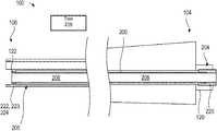
- FIGS. 1A-1Eillustrate an embodiment of a surgical instrument 100 including a removable working channel 200 .
- FIG. 1Aillustrates a side view of the surgical instrument 100 .
- FIG. 1Billustrates a cross-sectional view of the removable working channel 200 .
- FIG. 1Cillustrates a cross-sectional view of a proximal portion 104 and a distal portion 106 of the surgical instrument 100 , with the removable working channel 200 positioned within the surgical instrument 100 .
- FIG. 1Dillustrates a cross-sectional view of the proximal portion 104 and the distal portion 106 of the surgical instrument 100 , with the removable working channel 200 removed from the surgical instrument 100 .
- FIG. 1Eillustrates a perspective view of a distal portion 106 of the surgical instrument 100 .
- FIGS. 1A-1Eare discussed together in portions of the description below due to the overlap of depicted features.
- an example surgical instrument 100that includes a proximal portion 104 and a distal portion 106 and may include at least one instrument channel 102 extending therethrough.
- the surgical instrument 100may further comprise one or more coupling members (not shown here but described in greater detail below) at or near the proximal portion 104 and/or the distal portion 106 of the surgical instrument 100 .
- the surgical instrument 100 disclosed in FIG. 1Ais described within the context of endoscopic procedures, it will be appreciated that the surgical instrument 100 may include other types of instruments suitable for types of medical procedures.
- examples of the surgical instrument 100include but are not limited to an endoscope, a bronchoscope, a sinuscope, a nasopharyngoscope, a laryngoscope, a laparoscope, a gastroscope, a colonoscope, a hysteroscope, a cystoscope, a uroscope, a urethroscope, a cardioscope, an arthroscope, etc.
- the instrument channel 102may have a diameter ranging from about 1.2 mm to about 6 mm. More specifically, the instrument channel 102 may have a diameter about 2.8 mm, about 3.7 mm, about 4.2 mm, and about 6 mm. In some embodiments, the instrument channel 102 may be substantially straight along its longitudinal axis, as illustrated in FIG. 1A . In other embodiments, at least a portion of the instrument channel 102 may be curved. It is to be appreciated that the shape of the instrument channel 102 may depend on how the surgical instrument 100 is actuated or flexed.
- the instrument channel 102 of the surgical instrument 100is configured to receive a removable working channel 200 (drawn with dotted lines to indicate that the removable working channel 200 is inside the surgical instrument 100 ) such that the removable working channel 200 can be inserted into and/or removed from the instrument channel 102 .
- the removable working channel 200may be installed within the instrument channel 102 such that an outer surface of the removable working channel 200 interfaces the inner surface of the instrument channel 102 .
- the removable working channel 200when installed within the instrument channel 102 , protects the inner surface of the instrument channel 102 from wear and tear caused by medical tools when passed through the surgical instrument 100 .
- the removable working channel 200includes a proximal region 205 , a distal region 207 , and an inner surface 212 defining a lumen 208 .
- the lumen 208 of the removable working channel 200may be a working area usable for the passage of intraoperative instruments, generally referred to herein as medical tools.
- one or more additional channelsmay be incorporated to provide further capabilities, such as, for example, flush/irrigation, aspiration, illumination, laser energy, etc.
- the lumen 208 of the removable working channel 200may also be configured to deliver a variety of therapeutic substances along with a tool configured to pass through the removable working channel 200 . These substances may be delivered precisely to a target site using the insertion, articulation, and/or other capabilities of the surgical instrument 100 of the present disclosure.
- the removable working channel 200comprises a shaft 202 and may further comprise one or more locking members 220 and 222 at or near a proximal region 204 and at or near a distal region 206 of the removable working channel 200 , respectively.
- the phrase “locking member”may refer to a mechanism for securing the removable working channel to the surgical instrument.
- the shaft 202includes the proximal region 205 , the distal region 207 , and the lumen 208 extending therethrough.
- the shaft 202includes a wall 210 comprising the inner surface 212 and an outer surface 214 .
- the inner surface 212 of the shaft 202defines the lumen 208 extending along the longitudinal length of the shaft 202 .
- the outer diameter of the shaft 202may be substantially similar to, equal to, or less than the inner diameter of the instrument channel 102 of the surgical instrument 100 .
- One example of the removable working channel 200can define a shaft having an outer diameter that is greater than or equal to about 1.2 mm, or less than or equal to about 6 mm.
- the removable working channel 200may have a shaft having an outer diameter of about 3.2 mm.
- the thickness of the shaft wall 210may be greater than or equal to about 0.1 mm or less than or equal to about 0.3 mm.
- the shaft 202 of the removable working channel 200may be made of plastic materials or extruded plastic.
- the shaft 202may be made of at least one of polyether block amide (PEBA), Nylon, and polytetrafluoroethylene (PTFE), high-density polyethylene (HDPE), low-density polyethylene (LDPE), linear low density poly ethylene (LLDPE), polyvinyl chloride (PVC), polystyrene, acrylonitrile butadiene styrene (ABS), polypropylene (PP), thermoplastic elastomers (TPE), fluorinated ethylene propylene (FEP), acetal copolymer, polysulfone, polyetheretherketone (PEEK), polyetherimide, polyphenylene oxide (PPO), perfluoroalkoxy (PFA) plastic, polyvinylidene fluoride (PVDF), ethylene tetrafluoroethylene (ETFE), ethylene chlorotrifluoro
- PEBApoly
- the shaft 202 of the removable working channel 200may further comprise an inner liner (not shown) attached to the inner surface 212 of the shaft 202 .
- the inner linermay be made of at least one of PTFE, HDPE, LDPE, or LLDPE, or other similar medical grade extrusions.
- the inner linermay reduce friction and facilitate the passing of medical instruments through the lumen 208 of the removable working channel 200 .
- a lubricantmay be added to the surface of the inner liner or the inner surface 212 of the removable working channel 200 to further reduce friction between the surface of the inner liner or the inner surface 212 and the medical instruments.
- the shaft 202may further comprise a reinforcement member disposed at least partially between the inner surface 212 and the outer surface 214 of the shaft 202 .
- the reinforcement membermay be disposed inside the inner surface 212 of the shaft 202 or outside the outer surface 214 of the shaft 202 . Examples of the reinforcement member include one or more coils, one or more braids, or one or more cable tubes.
- the coils, the braids, and/or the cable tubesmay be at least partially made of stainless steel (e.g., stainless steel 304 or stainless steel 316 ), copper, other metals, Nitinol alloy, graphite, or polymers such as polyparaphenylene terephthalamide (e.g., tradename Kevlar), Ultra-high-molecular-weight polyethylene (UHMWPE) (e.g., tradename Spectra), PEEK, or nylon.
- stainless steele.g., stainless steel 304 or stainless steel 316
- copperother metals
- Nitinol alloye.g., Nitinol alloy
- graphitee.g., graphite
- polymerssuch as polyparaphenylene terephthalamide (e.g., tradename Kevlar), Ultra-high-molecular-weight polyethylene (UHMWPE) (e.g., tradename Spectra), PEEK, or nylon.
- UHMWPEUltra-high
- the removable working channel 200may further comprise the one or more locking members 220 at or near the proximal region 204 of the removable working channel 200 .
- the one or more locking members 220may be configured to releasably couple with the surgical instrument (not shown; see e.g., the surgical instrument 100 in FIG. 1A ).
- the one or more locking members 220may be at the proximal end of the removable working channel 200 .
- the one or more locking members 220may be placed anywhere in the proximal region 204 of the removable working channel 200 .
- the removable working channel 200may further comprise the one or more locking members 222 at or near the distal region 206 of the removable working channel 200 .
- the one or more locking members 222may be configured to releasably couple with the surgical instrument (not shown). As shown in FIG. 1B , the one or more locking members 222 may be at the distal end of the removable working channel 200 . In other examples, the one or more locking members 222 may be placed anywhere in the distal region 206 of the removable working channel 200 .
- FIG. 1Cthere is shown a cross-sectional view of the surgical instrument 100 and the removable working channel 200 inside the surgical instrument 100 .
- the removable working channel 200is configured to be installed within the surgical instrument 100 .
- the one or more locking members 220 at the proximal end of the removable working channel 200may be configured to releasably couple with the one or more coupling members 120 of the surgical instrument 100 .
- the surgical instrument 100does not comprise one or more coupling members 120 at or near the proximal portion 104 (not shown)
- the one or more locking members 220may be configured to releasably couple to the proximal portion 104 of the surgical instrument 100 .
- the one or more locking members 222 at the distal end of the removable working channel 200may be configured to releasably couple with the one or more coupling members 122 of the surgical instrument 100 .
- the one or more locking members 220may be configured to releasably couple to the distal portion 106 of the surgical instrument 100 .
- the locking members 220 and 222 of the removable working channel 200 on the proximal region 204 and the distal region 206may comprise a removable luer fit component 223 , a clamp, a friction fit component (also known as interference fit), a latch, a threaded fit component 224 , a slip fit component, a bayonet, a ball spring or pogo latch, a detent, a magnet, a screw lock, a snap fit component, or an O-ring component.
- the locking members 220 and/or 222may comprise a removable luer fit component configured to fit into a complementary removable luer fit component of the surgical instrument 100 .
- the locking members 220 and/or 222may comprise a clamp configured to removably hold at least a portion of the surgical instrument 100 (e.g., proximal portion 104 or distal portion 106 ).
- the locking members 220 and/or 222may comprise a friction fit component configured to slip into the instrument channel 102 of the surgical instrument 100 and lock by friction with the inner surface of the instrument channel 102 .
- the locking members 220 and/or 222may comprise a latch configured to join or fasten to a latch component of the surgical instrument 100 or directly to a portion of the surgical instrument 100 .
- the latchmay comprise (1) a ball with a spring or (2) a pogo latch.
- the locking members 220 and/or 222may comprise a threaded fit component configured to rotatably fit and lock into the instrument channel 102 of the surgical instrument 100 via an interlocking between threads of the threaded fit component and those on the inner surface of the instrument channel 102 .
- the locking members 220 and/or 222may comprise a slip fit component configured to fit and lock into the instrument channel 102 of the surgical instrument 100 .
- the locking members 220 and/or 222may comprise a bayonet component.
- the bayonet componentmay comprise a catch, a detent, or a pin configured to removably couple to a receptor (e.g., a hole, a groove, or an L-shaped groove) on the inner surface of the instrument channel 102 of the surgical instrument 100 .
- the bayonet component of the removable working channel 200may be a receptor (e.g., a hole, a groove, or an L-shaped groove) configured to receive a catch, a detent, or a pin on the inner surface of the instrument channel 102 of the surgical instrument 100 .
- the locking members 220 and/or 222may comprise a magnet configured to interact with a magnet at or near the instrument channel 102 of the surgical instrument 100 .
- the locking members 220 and/or 222may comprise a screw lock configured to rotatably lock the removable working channel 200 to the surgical instrument 100 via an interlocking between threads of the screw lock and those on the surgical instrument 100 .
- the locking members 220 and/or 222may comprise an O-ring component configured to be placed inside and seal against the instrument channel 102 of the surgical instrument 100 .
- the locking members 220 and/or 222 of the removable working channel 200may comprise one or more locking components configured to engage with a tool 216 .
- the locking members 220 and/or 222may be releasable from the surgical instrument 100 when, in use, the tool 216 engages and actuates the locking components.
- the tool 216may be configured to selectively actuate and release certain type or types of the locking components.
- the tool 216may be a key that is configured to engage and unlock only one type of the locking components. The key may be configured such that the key is not able to engage or unlock other types of the locking components.
- the tool 216may be configured to wirelessly communicate with the locking components to actuate them.
- the surgical instrument 100is configured to receive the removable working channel 200 .
- the surgical instrument 100may further comprise one or more coupling members 122 at or near the distal portion 106 of the surgical instrument 100 .
- the one or more coupling members 122 of the surgical instrument 100may be configured to releasably couple with the one or more locking members 222 of the removable working channel 200 .
- the one or more coupling members 122may be configured to releasably couple to the distal region 206 of the removable working channel 200 . Examples of the coupling members 122 of the surgical instrument 100 are explained below.
- the one or more coupling members 122may be at the distal end of the surgical instrument 100 . In other embodiments, the one or more coupling members 122 may be placed anywhere in the distal portion 106 of the surgical instrument 100 .
- the surgical instrument 100may further comprise one or more coupling members 120 at or near the proximal portion 104 of the surgical instrument 100 .
- the one or more coupling members 120 of the surgical instrument 100may be configured to releasably couple with the one or more locking members 220 of the removable working channel 200 .
- the removable working channel 200does not comprise one or more locking members at or near the proximal region 204 of the removable working channel 200 (not shown)
- the one or more coupling members 120may be configured to releasably couple to the proximal region 204 of the removable working channel 200 .
- the one or more coupling members 120may comprise a clamp mechanism configured to couple to or pinch at the proximal region 204 of the removable working channel 200 .
- the one or more coupling members 120may be at the proximal end of the surgical instrument 100 . In other embodiments, the one or more coupling members 120 may be placed anywhere in the proximal portion 104 of the surgical instrument 100 .
- the coupling members 120 and 122 on the proximal portion 104 and the distal portion 106 , respectively, of the surgical instrument 100may comprise a removable luer fit component, a clamp, a friction fit component (also known as an interference fit component), a latch, a threaded fit component, a slip fit component, a bayonet, a ball spring or pogo latch, a detent, a magnet, a screw lock, a snap fit component, or an O-ring component.
- the coupling members 120 and/or 122 of the surgical instrument 100may comprise a removable luer fit component configured to fit into a complementary removable luer fit component of the removable working channel 200 .
- the coupling members 120 and/or 122may comprise a clamp configured to removably hold at least a portion of the removable working channel 200 .
- the coupling members 120 and/or 122may comprise a friction fit component configured to lock by friction with the outer surface of the removable working channel 200 .
- the coupling members 120 and/or 122may comprise a latch configured to join or fasten to a latch component of the removable working channel 200 or directly to a portion of the removable working channel 200 .
- the latchmay comprise (1) a ball with a spring and/or (2) a pogo latch.
- the coupling members 120 and/or 122may comprise a threaded fit component configured to rotatably fit and lock with the removable working channel 200 via an interlocking between threads of the threaded fit component and those on the outer surface of the removable working channel 200 .
- the coupling members 120 and/or 122may comprise a slip fit component configured to fit and lock with the removable working channel 200 .
- the coupling members 120 and/or 122may comprise a bayonet component.
- the bayonet componentmay comprise a catch, a detent, or a pin configured to removably couple to a receptor (e.g., a hole, a groove, or an L-shaped groove) on the outer surface of the removable working channel 200 .
- the bayonet component of the surgical instrument 100may be a receptor (e.g., a hole, a groove, or an L-shaped groove) configured to receive a catch, a detent, or a pin on the outer surface of the removable working channel 200 .
- the coupling members 120 and/or 122may comprise a magnet configured to interact with a magnet placed on the removable working channel 200 .
- the coupling members 120 and/or 122may comprise a screw lock configured to rotatably lock at least a portion of the surgical instrument 100 to at least a portion of the removable working channel 200 via an interlocking between threads of the screw lock and those on the removable working channel 200 .
- the coupling members 120 and/or 122may comprise an O-ring component configured to be seal against the removable working channel 200 .
- the coupling members 120 and/or 122 of the surgical instrument 100may comprise one or more locking components configured to engage with a tool 216 .
- the coupling members 120 and/or 122 of the surgical instrument 100may be configured to be released from the removable working channel 200 when the tool 216 engages and actuates the locking components of the coupling members 120 and/or 122 .
- the tool 216may be configured to selectively actuate and release certain type or types of the locking components.
- the tool 216may be a key that is configured to engage and unlock only one type of the locking components. The key may be configured such that the key is not able to engage or unlock other types of the locking components.
- the tool 216may wirelessly communicate with the locking components to actuate them.
- the surgical instrument 100may comprise a sensor and/or a detector configured to communicate with a processor (e.g., of a surgical robotic system or a computing device in communication with the surgical robotic system) configured to process or verify the information received from the at least one identification member of the removable working channel 200 .
- the user of the surgical instrument 100e.g., an operator, a physician, or a robotic surgical system
- the processormay set requirements as to which removable working channel 200 may be installed to the surgical instrument 100 .
- the processormay determine whether the removable working channel 200 satisfies the requirements set by the user.
- the surgical instrument 100may be configured to only receive a removable working channel 200 whose information is verified by the processor.
- the surgical instrument 100may be configured to receive only removable working channels 200 whose information satisfies a certain set of requirements set by the user.
- the surgical instrument 100may be configured to receive removable working channels 200 produced by verifiable manufacturers only or by a certain set of one or more manufacturers only.
- the surgical instrument 100may be configured to receive only removable working channels 200 that have not been used before.
- the processormay be configured to transmit a message or otherwise warn a user that one or more requirements of the removable working channel 200 have not been met (e.g., if the source or the manufacturer of the removable working channel 200 is not verifiable).
- FIG. 1Dthere is shown a cross-sectional view of the proximal portion 104 and the distal portion 106 of the surgical instrument 100 , with the removable working channel 200 removed from the surgical instrument 100 .
- the inner surface 109 of the instrument channel 102may be covered by a working channel sheath 110 .
- the working channel sheath 110may be configured to receive the removable working channel 200 as described herein.
- the removable working channel 200may be positioned inside the surgical instrument 100 such that the outer surface of the removable working channel 200 interfaces the inner surface 111 of the working channel sheath 110 .
- the working channel sheath 110may reduce friction between the inner surface 109 of the instrument channel 102 and the removable working channel 200 , facilitating the installation and/or removal processes for the removable working channel 200 .
- the inner surface 109 of the instrument channel 102may not be covered with the working channel sheath 110 .
- the working channel sheath 110may be made of plastic or extruded plastic.
- the working channel sheath 110may be made of at least one of PEBA, Nylon, PTFE, HDPE, LDPE, LLDPE, PVC, polystyrene, ABS, PP, TPE, FEP, acetal copolymer, polysulfone, PEEK, polyetherimide, PPO, PFA plastic, PVDF, ETFE, ECTFE, and THV copolymer, or other similar medical grade extrusions.
- the working channel sheath 110may further comprise an inner liner attached to the inner surface 111 of the working channel sheath 110 .
- the inner linermay be made of at least one of PTFE, HDPE, LDPE, LLDPE, or other similar medical grade extrusions, or hydrophilic materials.
- the hydrophilic inner liner coatingmay be useful for some applications such as tissue/stone removal or easing the passage of medical tools.
- the working channel sheath 110may further comprise one or more coils, one or more braids, or one or more cable tubes.
- the coils, the braids, and/or the cable tubesmay be at least partially inside the working channel sheath 110 .
- the coils, the braids, and/or the cable tubesmay be disposed inside the inner surface 111 of the working channel sheath 110 or outside the outer surface of the working channel sheath 110 .
- the coils, the braids, and/or the cable tubesmay be at least partially made of stainless steel (e.g., stainless steel 304 or stainless steel 316 ), copper, other metals, Nitinol alloy, graphite, or polymers such as polyparaphenylene terephthalamide (e.g., tradename Kevlar), UHMWPE (e.g., tradename Spectra), PEEK, or nylon. It is to be appreciated that other materials may be used depending on the application and the materials just described are not provided in a limiting manner.
- the distal portion 106 of the surgical instrument 100may comprise the distal region 107 of the instrument channel 102 , light sources 150 (e.g., light emitting diode (LED), optic fiber, etc.), and a camera 155 (e.g., charge-coupled device (CCD) or complementary metal-oxide-semiconductor (CMOS) camera, terminal end of imaging fiber bundle etc.).
- light sources 150e.g., light emitting diode (LED), optic fiber, etc.
- a camera 155e.g., charge-coupled device (CCD) or complementary metal-oxide-semiconductor (CMOS) camera, terminal end of imaging fiber bundle etc.
- the camera 155may be used, for example, to capture real-time video to assist with navigation within anatomical structures.
- Other channels or operating electronicsmay be provided along the surgical instrument 100 to provide various known capabilities at the distal portion 106 , such as wiring to the camera 155 , insufflation, suction, electricity, fiber optics, ultrasound transducer, electromagnetic (EM) sensing, and optical coherence tomography (OCT) sensing.
- EMelectromagnetic
- OCToptical coherence tomography
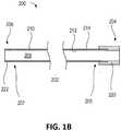
- FIGS. 2A-2Billustrate aspects of another embodiment of a surgical instrument 300 including a removable working channel 400 as described herein, wherein the surgical instrument 300 comprises an endoscope and includes (1) a removable luer adapter 320 at the proximal portion 304 of the surgical instrument 300 and (2) a snap fit component 322 at the distal portion 306 of the surgical instrument 300 ; and the removable working channel 400 comprises (1) a removable luer component 420 at the proximal region 404 of the removable working channel 400 and (2) a snap fit component 422 at the distal region 406 of the removable working channel 400 .
- FIG. 2Aillustrates a cross-sectional view of a distal portion 306 of the surgical instrument 300 .
- FIG. 2Billustrates a cross-sectional view of a proximal portion 304 of the surgical instrument 300 .
- FIGS. 2A-2Bare discussed together in portions of the description below due to the overlap of depicted features.
- components that can be similar to components described above with reference the embodiment of FIGS. 1A-1E and the description aboveare identified by similar numbers wherein the reference number used is preceded by the numbers “3” and “4” instead of “1” and “2”, respectively.
- components 302 , 304 and 306can be similar to components 102 , 104 and 106
- components 402 , 404 and 406can be similar to components 202 , 204 and 206 . Reference can be made to the description above for additional descriptions and embodiments of these components which can be used with the embodiment of FIGS. 2A-2B .
- the surgical instrument 300may include at least one instrument channel 302 extending along its longitudinal length.
- an embodiment of the surgical instrument 300comprising an endoscope.
- the instrument channel 302 of the surgical instrument 300is configured to receive a removable working channel 400 such that the removable working channel 400 can be inserted into, positioned within, attached to, and/or removed from the instrument channel 302 .
- At least a portion of the inner surface of the instrument channel 302 of the surgical instrument 300may be covered with a working channel sheath 310 .
- An outer surface of the working channel sheath 310interfaces with the inner surface of the instrument channel 302
- an inner surface of the working channel sheath 310interfaces with the instrument channel 302 .
- the working channel sheath 310is configured to receive the removable working channel 400 as described herein.
- the surgical instrument 300includes a snap fit component 322 near the distal end of the surgical instrument 300 .
- the snap fit component 322may be placed anywhere in the distal portion 306 of the surgical instrument 300 .
- the snap fit component 322comprises a step portion configured to abut a distal region 406 of the removable working channel 400 .
- the diameter of the instrument channel 302increases such that the distal portion of the instrument channel 302 can receive the distal region 406 of the removable working channel 400 .
- the removable working channel 400comprises a snap fit component 422 near the distal end of the removable working channel 400 .
- the snap fit component 422may be placed anywhere in the distal region 406 of the removable working channel 400 .
- the snap fit component 422is configured to annularly surround the outer surface of the distal region 406 of the removable working channel 400 . That way, the outer diameter of the removable working channel 400 at its distal region 406 is greater than that at other regions of the removable working channel 400 .
- the snap fit component 422may be integrally formed to the distal region 406 of the removable working channel 400 . It is to be appreciated that an interference fit component and/or a slip fit component may be used in the distal portion 306 of the surgical instrument 300 instead of or in addition to the snap fit component 322 for simplicity.
- the snap fit component 422 of the removable working channel 400is configured to releasably couple to the snap fit component 322 of the surgical instrument 300 .
- the outer diameter of the distal region 406 of the removable working channel 400is greater than the diameter of the instrument channel 302 at or near its proximal end.
- the distal region 406 of the removable working channel 400is folded toward the radially inward direction in order for the removable working channel 400 to be able to pass through the instrument channel 302 .
- the removable working channel 400may be at least partially made of one or more compressible materials.
- the userwhen inserting the removable working channel 400 into a proximal end of the instrument channel 302 , the user may use a tool (e.g., a mandrel with a handle) to move the removable working channel 400 into the instrument channel 302 .
- a toole.g., a mandrel with a handle
- the diameter of the instrument channel 302becomes greater to be substantially similar to the outer diameter of the distal region 406 of the removable working channel 400 .
- the distal region 406 of the removable working channel 400radially expands from its folded state to conform to the shape of the instrument channel 302 at the distal portion 306 .
- the distal region 406 of the removable working channel 400abuts the step portion of the snap fit component 322 of the surgical instrument 300 , which prevents a further distal movement of the removable working channel 400 .
- the snap fit component 322 of the surgical instrument 300may comprise an annular recess on an inner surface at or near the distal end of the instrument channel 302
- the snap fit component 422 of the removable working channel 400may comprise an annular ring on its outer surface.
- the annular ring of the removable working channel 400may be configured to snap into and removably couple with the annular recess of the instrument channel 302 .
- the snap fit component 422 of the removable working channel 400may comprise a spring clamp on its outer surface.
- the spring clamp of the removable working channel 400may be configured to snap into and removably couple with the annular recess of the instrument channel 302 .
- the snap fit component 322 of the surgical instrument 300may comprise a wire spring clamp embedded at or near the distal end of the instrument channel 302 (e.g., on the inner surface at or near the distal end of the instrument channel 302 ).
- the wire spring clampmay be configured to removably hold the distal region 406 of the removable working channel 400 .
- the releasable coupling between the two snap fit components 322 and 422is at least partially achieved by friction between the inner surface of the instrument channel 302 at or near the distal portion 306 and the snap fit component 422 of the removable working channel 400 .
- the snap fit component 422 of the removable working channel 400slides in a proximal direction, so the diameter of the instrument channel 302 contacting the snap fit component 422 becomes smaller.
- the snap fit component 422 of the removable working channel 400is forced into the portion of the instrument channel 302 outside the distal region 406 whose diameter is smaller than the outer diameter of the distal region 406 of the removable working channel 400 .
- the snap fit component 422 of the removable working channel 400is pushed against the inner surface of the instrument channel 302 , causing frictions resisting the uncoupling between the two snap fit components 322 and 422 .
- the coupling between the two snap fit components 322 and 422is not permanent and may be released by enough pulling force and/or manipulation of the distal region 406 of the removable working channel 400 (e.g., pulling the distal region 406 toward the radially inward direction) that overcomes the forces of the snap fit.
- one or more toolsmay be used to remove the removable working channel 400 from the instrument channel 302 .
- the removable working channel 400comprises a removable luer component 420 at the proximal region 404 of the removable working channel 400 .
- the surgical instrument 300includes a removable luer adapter 320 at the proximal portion 304 of the surgical instrument 300 .
- the removable luer component 420 of the removable working channel 400is configured to releasably couple to the removable luer adapter 320 of the surgical instrument 300 .
- the removable luer component 420 of the removable working channel 400may be configured to slip and fit into the removable luer adapter 320 of the surgical instrument 300 .
- the removable luer component 420 of the removable working channel 400may be configured to rotatably fit and lock into the removable luer adapter 320 of the surgical instrument 300 .
- FIGS. 3A-3Billustrate yet another embodiment of a surgical instrument 500 including a removable working channel 600 as described herein, wherein the surgical instrument does not comprise one or more coupling members at or near the distal portion 506 of the surgical instrument 500 .
- FIG. 3Aillustrates a cross-sectional view of the surgical instrument 500 as described herein.
- FIG. 3Billustrates a cross-sectional view of the removable working channel 600 as described herein.
- FIGS. 3A-3Bare discussed together in portions of the description below due to the overlap of depicted features.
- components that can be similar to components described above with reference the embodiment of FIGS. 1A-1E and the description aboveare identified by similar numbers wherein the reference number used is preceded by the numbers “5” and “6” instead of “1” and “2”, respectively.
- components 502 , 504 and 506can be similar to components 102 , 104 and 106
- components 602 , 604 and 606can be similar to components 202 , 204 and 206 .
- the surgical instrument 500may include at least one instrument channel 502 extending along its longitudinal length. Similar to the surgical instrument 100 of FIGS. 1A-1E , the instrument channel 502 of the surgical instrument 500 is configured to receive the removable working channel 600 such that the removable working channel 600 can be inserted into and/or removed from the instrument channel 502 .
- a portion of the inner surface of the instrument channel 502 of the surgical instrument 500is covered with a working channel sheath 510 .
- a working channel sheath 510As shown in FIG. 3A , an outer surface of the working channel sheath 510 interfaces with the inner surface of the instrument channel 502 , and an inner surface of the working channel sheath 510 interfaces with the instrument channel 502 .
- the working channel sheath 510is configured to receive the removable working channel 600 as described herein.
- the surgical instrument 500does not comprise one or more coupling members at or near the distal portion 506 of the surgical instrument 500 .
- the distal portion 506 of the surgical instrument 500is not configured to lock or couple to the removable working channel 600 .
- the surgical instrument 500comprises one or more coupling members 520 at the proximal portion 504 of the surgical instrument 500 .
- the coupling members 520 of the surgical instrument 500may comprise a removable luer fit component, a clamp, a friction fit component (also known as an interference fit component), a latch, a threaded fit component, a slip fit component, a bayonet, a ball spring or pogo latch, a detent, a magnet, a screw lock, a snap fit component, or an O-ring component.
- FIG. 3Billustrates a cross-sectional view of the removable working channel 600 .
- the removable working channel 600comprises a shaft 602 .
- the shaft 602includes a proximal end 605 , a distal end 607 , and a lumen 608 extending therethrough.
- the shaft 602includes a wall 610 comprising an inner surface 612 and an outer surface 614 .
- the inner surface 612 of the shaft 602defines the lumen 608 extending along the longitudinal length of the shaft 602 .
- the outer surface 614 of the shaft 602when installed, interfaces with the instrument channel 502 of the surgical instrument (not shown).
- the removable working channel 600further comprises one or more locking members 620 at the proximal region 604 of the removable working channel 600 .
- the locking members 620 of the removable working channel 600are configured to releasably couple to the coupling members 520 of the surgical instrument 500 .
- the locking members 620 of the removable working channel 600are configured to releasably couple to the proximal portion 504 of the surgical instrument 500 .
- the locking members 620 of the removable working channel 600may comprise a removable luer fit component, a clamp, a friction fit component (also known as an interference fit component), a latch, a threaded fit component, a slip fit component, a bayonet, a ball spring or pogo latch, a detent, a magnet, a screw lock, a snap fit component, or an O-ring component.
- the removable working channel 600does not comprise one or more locking members at or near the distal region 606 of the removable working channel 600 such that the distal region 606 of the removable working channel 600 is not configured to lock or couple to the distal portion 506 of the surgical instrument 500 .
- FIG. 4illustrates another embodiment of a removable working channel 700 as described herein, wherein the removable working channel 700 further comprises an identification member 730 .
- components that can be similar to components described above with reference the embodiment of FIG. 1B and the description aboveare identified by similar numbers wherein the reference number used is preceded by the numbers “7” instead of “2”, respectively.
- components 702 , 704 and 706can be similar to components 202 , 204 and 206 , respectively. Reference can be made to the description above for additional descriptions and embodiments of these components which can be used with the embodiment of FIG. 4 .
- the removable working channel 700comprises a shaft 702 including a proximal end 705 , a distal end 707 , and a lumen 708 extending therethrough.
- the shaft 702includes a wall 710 comprising an inner surface 712 and an outer surface 714 .
- the inner surface 712 of the shaft 702defines the lumen 708 extending along the longitudinal length of the shaft 702 .
- the outer surface 714 of the shaft 702when installed, interfaces with the instrument channel of the surgical instrument (not shown).
- the removable working channel 700may further comprise one or more locking members 720 at the proximal region 704 of the removable working channel 700 and/or one or more locking members 722 at the distal region 706 of the removable working channel 700 .
- the locking members 720 and/or 722 of the removable working channel 700are configured to releasably couple to the surgical instrument (not shown) as described above.
- the locking members 720 and/or 722 of the removable working channel 700may comprise a removable luer fit component, a clamp, a friction fit component (also known as an interference fit component), a latch, a threaded fit component, a slip fit component, a bayonet, a ball spring or pogo latch, a detent, a magnet, a screw lock, a snap fit component, or an O-ring component.
- the removable working channel 700further comprises one or more identification members 730 configured to store data comprising information regarding the surgical instrument (e.g., one similar to the surgical instrument 100 ), the removable working channel 700 , or both.
- the identification member 730may be attached to the shaft 702 (e.g., on the inner surface 712 or the outer surface 714 ), or to the locking members 720 and/or 722 .
- Examples of the identification members 730may include, but not be limited to, a radio-frequency identification (RFID) tag, a near field communication (NFC) tag, a bar code, a Quick Response (QR) code, a Bluetooth low energy (BLE) tag, an ultrasound identification tag, an infrared identification tag, or a video identification tag.
- RFIDradio-frequency identification
- NFCnear field communication
- QRQuick Response
- BLEBluetooth low energy
- the data saved in the identification members 730may include a source, type, material, dimension, manufacture date, expiration date, and/or identification number of the surgical instrument or the removable working channel 700 .
- one or more identification members 730may be installed on the surgical instrument, the removable working channel 700 , or both.
- the surgical instrument, the removable working channel 700 , or bothmay further comprise at least one sensor or detector configured to read data from the identification members 730 .
- a toolmay be configured to couple and/or uncouple between a removable working channel (e.g., removable working channel 200 , 400 , or 600 as described above) and a surgical instrument (e.g., surgical instrument 100 , 300 , or 500 as described above).
- the removable working channel and/or the surgical instrumentmay be configured to couple and/or uncouple to each other only through the use of a specific type of the tool. This way, only people with the specific type of the tool may install and/or remove the removable working channel onto/from the surgical instrument.
- the toolmay be configured to adjust an attachment between the removable working channel and the surgical instrument.
- the toolmay comprise an actuator configured to engage and actuate at least one of (i) one or more locking members (e.g., locking members 220 , 420 , and/or 620 as described above) at the proximal region of the removable working channel and (ii) one or more coupling members (e.g., coupling members 120 , 320 , and/or 520 as described above) at the proximal portion of the surgical instrument.
- locking memberse.g., locking members 220 , 420 , and/or 620 as described above
- coupling memberse.g., coupling members 120 , 320 , and/or 520 as described above
- the actuatormay be configured to engage and actuate at least one of (i) one or more locking members (e.g., locking members 222 and/or 422 as described above) at the distal region of the removable working channel and (ii) one or more coupling members (e.g., coupling members 122 and/or 322 as described above) at the distal portion of the surgical instrument.
- one or more locking memberse.g., locking members 222 and/or 422 as described above
- coupling memberse.g., coupling members 122 and/or 322 as described above
- the engagement and actuation of the at least one of (i) one or more locking members and (ii) one or more coupling members by the actuatorfacilitates locking and/or unlocking an attachment between the removable working channel and the surgical instrument.
- the toolmay be configured to wirelessly communicate with the one or more locking members of the removable working channel to engage or actuate the one or more locking members.
- the toolmay be configured to wirelessly communicate with the one or more coupling members of the surgical instrument to engage or actuate the one or more coupling members. Examples of the tool include, and are not limited to, a key, a driver, a pipe, a needle, and a transmitter.
- the actuator of the toolmay be configured to be able to engage only with a certain type or types of the locking members and/or the coupling members. Such an exclusive engagement may be enabled by (1) physical features of the actuator, the locking members, and/or the coupling members or (2) electronic or wireless communications between the tool and the locking members or the coupling members.
- the actuator of the toolmay have a physical shape that can engage with only a certain type or types of the locking members and/or the coupling members.
- the toolmay be configured to wirelessly communicate with the locking members and/or the coupling members to allow engagement with only a certain type or types of the locking members and/or the coupling members.
- a usermay sanitize or replace the surgical instrument by removing a removable working channel installed in an instrument channel of the surgical instrument, checking the integrity of the removable working channel, and then either (1) cleaning and reinstalling the removable working channel or (2) replacing the removable working channel with a new removable working channel in the surgical instrument, depending on the integrity of the first removable working channel.
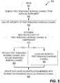
- FIG. 5depicts a flowchart illustrating an embodiment of a process 800 of sanitizing or replacing one or more removable working channels (e.g., removable working channels 200 , 400 , 600 , and 700 as described above) of a surgical instrument described herein (e.g., surgical instruments 100 , 300 , and 500 as described above), wherein the process 800 may be conducted by a user.
- the usermay include, but not be limited to, hospitals, physicians, healthcare practitioners, third-party cleaning service companies, medical device companies, and/or autonomous systems.
- the process 800may also be implemented, entirely or in part, by an automated system (e.g., robotic system). It will be appreciated that although components described in the process 800 may be identified by the reference numbers used for the embodiment of FIGS. 1A-1E , these components are not limited to the embodiment of FIGS. 1A-1E .
- the usermay remove a first removable working channel from a surgical instrument.
- removing the first removable working channelmay comprise removing the removable working channel 200 out of the proximal end of the instrument channel 102 .
- block 805may involve (1) engaging a tool to at least one of (i) the one or more coupling members 120 and/or 122 of the surgical instrument 100 and (ii) the one or more locking members 220 and/or 222 of the first removable working channel 200 ; (2) actuating the tool to release the one or more coupling members 120 and/or 122 of the surgical instrument 100 from the one or more locking members 220 and/or 222 of the first removable working channel 200 ; and (3) removing the first removable working channel 200 from the surgical instrument 100 .
- the usermay analyze the integrity of the first removable working channel.
- the usermay check the duration of usage of the first removable working channel 200 .
- the usermay check the duration of usage of the first removable working channel 200 by accessing data from one or more identification members attached to the first removable working channel 200 (e.g., identification members 730 or one or more RFID tags).
- the usermay determine whether the integrity of the first removable working channel is compromised.
- the standard(s) or factor(s) for deciding whether the removable working channel 200 is compromisedmay be pre-determined by the user. Additionally or alternatively, the determination of whether the integrity of the first removable working channel is compromised may be determined based on detecting cases of wear and tear, such as areas that include scrapes, holes, or any other signs of wear and tear.
- replacing the first removable working channel with the second removable working channelmay involve inserting the distal region 206 of the second removable working channel 200 through the proximal end of the instrument channel 102 of the surgical instrument 100 until the distal region 206 of the second removable working channel 200 reaches near the distal end of the instrument channel 102 .
- block 820may involve inserting the distal region 206 of the second removable working channel 200 through the proximal end of the instrument channel 102 of the surgical instrument 100 until at least one of the one or more coupling members 120 and/or 122 of the surgical instrument 100 engages with at least one of the one or more locking members 220 and/or 222 of the second removable working channel 200 .
- the usermay clean and reinstall the first removable working channel in the instrument channel of the surgical instrument.
- reinstalling the first removable working channel 200 in the instrument channel 102 of the surgical instrument 100may involve inserting the distal region 206 of the first removable working channel 200 through the proximal end of the instrument channel 102 of the surgical instrument 100 until the distal region 206 of the first removable working channel 200 reaches or is near the distal end of the instrument channel 102 .
- reinstalling the first removable working channel 200 in the instrument channel 102 of the surgical instrument 100may involve inserting the distal region 206 of the first removable working channel 200 through the proximal end of the instrument channel 102 of the surgical instrument 100 until at least one of the one or more coupling members 120 and/or 122 of the surgical instrument 100 engages with at least one of the one or more locking members 220 and/or 222 of the first removable working channel 200 .
- the usermay optionally update data saved in the identification members with information regarding the installed working channel.
- the information regarding the installed working channelmay include information as to whether the first removable working channel is reinstalled in the surgical instrument (e.g., surgical instrument 100 ) or the second removable working channel is installed in the surgical instrument.
- the usermay use an RFID writer to update a data structure in the RFID tag that specifies whether the removable working channel has been replaced, a date that the removable working channel has been replaced, a count associated with a number of times the working channel has been sanitized but not replaced, or any other suitable data associated with the use or replacement of a removable working channel with respect to a surgical instrument.
- Implementations disclosed hereinprovide systems, methods and apparatus for increasing a service life of a surgical instrument. More specifically, implementations of the present disclosure relate to a removable working channel for a surgical instrument and to a surgical instrument configured to receive and interfere with the removable working channel.
- Couplemay indicate either an indirect connection or a direct connection.
- first componentmay be either indirectly connected to the second component via another component or directly connected to the second component.
- the methods described hereinmay be stored as one or more instructions on a processor-readable or computer-readable medium.
- computer-readable mediumrefers to any available medium that can be accessed by a computer or processor.
- a mediummay comprise RAM, ROM, EEPROM, flash memory, CD-ROM or other optical disk storage, magnetic disk storage or other magnetic storage devices, or any other medium that can be used to store desired program code in the form of instructions or data structures and that can be accessed by a computer.
- a computer-readable mediummay be tangible and non-transitory.
- codemay refer to software, instructions, code or data that is/are executable by a computing device or processor.
- the methods disclosed hereincomprise one or more steps or actions for achieving the described method.
- the method steps and/or actionsmay be interchanged with one another without departing from the scope of the claims.
- the order and/or use of specific steps and/or actionsmay be modified without departing from the scope of the claims.
- the term “plurality”denotes two or more. For example, a plurality of components indicates two or more components.
- the term “determining”encompasses a wide variety of actions and, therefore, “determining” can include calculating, computing, processing, deriving, investigating, looking up (e.g., looking up in a table, a database or another data structure), ascertaining and the like. Also, “determining” can include receiving (e.g., receiving information), accessing (e.g., accessing data in a memory) and the like. Also, “determining” can include resolving, selecting, choosing, establishing and the like.
Landscapes
- Health & Medical Sciences (AREA)
- Life Sciences & Earth Sciences (AREA)
- Surgery (AREA)
- Engineering & Computer Science (AREA)
- Physics & Mathematics (AREA)
- Veterinary Medicine (AREA)
- Public Health (AREA)
- General Health & Medical Sciences (AREA)
- Animal Behavior & Ethology (AREA)
- Biomedical Technology (AREA)
- Molecular Biology (AREA)
- Heart & Thoracic Surgery (AREA)
- Optics & Photonics (AREA)
- Nuclear Medicine, Radiotherapy & Molecular Imaging (AREA)
- Pathology (AREA)
- Medical Informatics (AREA)
- Radiology & Medical Imaging (AREA)
- Biophysics (AREA)
- Mechanical Engineering (AREA)
- Astronomy & Astrophysics (AREA)
- General Physics & Mathematics (AREA)
- Epidemiology (AREA)
- Surgical Instruments (AREA)
- Endoscopes (AREA)
Abstract
Description
Claims (21)
Priority Applications (2)
| Application Number | Priority Date | Filing Date | Title |
|---|---|---|---|
| US15/975,653US10716461B2 (en) | 2017-05-17 | 2018-05-09 | Exchangeable working channel |
| US16/931,240US11730351B2 (en) | 2017-05-17 | 2020-07-16 | Exchangeable working channel |
Applications Claiming Priority (2)
| Application Number | Priority Date | Filing Date | Title |
|---|---|---|---|
| US201762507709P | 2017-05-17 | 2017-05-17 | |
| US15/975,653US10716461B2 (en) | 2017-05-17 | 2018-05-09 | Exchangeable working channel |
Related Child Applications (1)
| Application Number | Title | Priority Date | Filing Date |
|---|---|---|---|
| US16/931,240ContinuationUS11730351B2 (en) | 2017-05-17 | 2020-07-16 | Exchangeable working channel |
Publications (2)
| Publication Number | Publication Date |
|---|---|
| US20180333044A1 US20180333044A1 (en) | 2018-11-22 |
| US10716461B2true US10716461B2 (en) | 2020-07-21 |
Family
ID=64269723
Family Applications (2)
| Application Number | Title | Priority Date | Filing Date |
|---|---|---|---|
| US15/975,653ActiveUS10716461B2 (en) | 2017-05-17 | 2018-05-09 | Exchangeable working channel |
| US16/931,240Active2039-04-12US11730351B2 (en) | 2017-05-17 | 2020-07-16 | Exchangeable working channel |
Family Applications After (1)
| Application Number | Title | Priority Date | Filing Date |
|---|---|---|---|
| US16/931,240Active2039-04-12US11730351B2 (en) | 2017-05-17 | 2020-07-16 | Exchangeable working channel |
Country Status (7)
| Country | Link |
|---|---|
| US (2) | US10716461B2 (en) |
| EP (1) | EP3624668A4 (en) |
| JP (1) | JP7301750B2 (en) |
| KR (1) | KR102576296B1 (en) |
| CN (1) | CN110769736B (en) |
| AU (1) | AU2018270785B2 (en) |
| WO (1) | WO2018213078A1 (en) |
Cited By (68)
| Publication number | Priority date | Publication date | Assignee | Title |
|---|---|---|---|---|
| US20190200846A1 (en)* | 2013-03-29 | 2019-07-04 | Fujifilm Corporation | Endoscopic surgery device |
| US10945904B2 (en) | 2019-03-08 | 2021-03-16 | Auris Health, Inc. | Tilt mechanisms for medical systems and applications |
| US20210076909A1 (en)* | 2018-07-19 | 2021-03-18 | Fujifilm Corporation | Endoscope aid and endoscope |
| US10959792B1 (en) | 2019-09-26 | 2021-03-30 | Auris Health, Inc. | Systems and methods for collision detection and avoidance |
| US11026758B2 (en) | 2017-06-28 | 2021-06-08 | Auris Health, Inc. | Medical robotics systems implementing axis constraints during actuation of one or more motorized joints |
| US11109928B2 (en) | 2019-06-28 | 2021-09-07 | Auris Health, Inc. | Medical instruments including wrists with hybrid redirect surfaces |
| US11135398B2 (en) | 2018-07-19 | 2021-10-05 | Neptune Medical Inc. | Dynamically rigidizing composite medical structures |
| US11147633B2 (en) | 2019-08-30 | 2021-10-19 | Auris Health, Inc. | Instrument image reliability systems and methods |
| US11206974B2 (en)* | 2016-02-09 | 2021-12-28 | Olympus Winter & Ibe Gmbh | Surgical instrument and method for producing a surgical instrument |
| US11207141B2 (en) | 2019-08-30 | 2021-12-28 | Auris Health, Inc. | Systems and methods for weight-based registration of location sensors |
| US11234780B2 (en) | 2019-09-10 | 2022-02-01 | Auris Health, Inc. | Systems and methods for kinematic optimization with shared robotic degrees-of-freedom |
| US11278703B2 (en) | 2014-04-21 | 2022-03-22 | Auris Health, Inc. | Devices, systems, and methods for controlling active drive systems |
| US11357586B2 (en) | 2020-06-30 | 2022-06-14 | Auris Health, Inc. | Systems and methods for saturated robotic movement |
| US11369386B2 (en) | 2019-06-27 | 2022-06-28 | Auris Health, Inc. | Systems and methods for a medical clip applier |
| US11382650B2 (en) | 2015-10-30 | 2022-07-12 | Auris Health, Inc. | Object capture with a basket |
| US11403759B2 (en) | 2015-09-18 | 2022-08-02 | Auris Health, Inc. | Navigation of tubular networks |
| US11439419B2 (en) | 2019-12-31 | 2022-09-13 | Auris Health, Inc. | Advanced basket drive mode |
| US11452844B2 (en) | 2013-03-14 | 2022-09-27 | Auris Health, Inc. | Torque-based catheter articulation |
| US11464591B2 (en) | 2015-11-30 | 2022-10-11 | Auris Health, Inc. | Robot-assisted driving systems and methods |
| US11497568B2 (en) | 2018-09-28 | 2022-11-15 | Auris Health, Inc. | Systems and methods for docking medical instruments |
| US11511079B2 (en) | 2014-07-01 | 2022-11-29 | Auris Health, Inc. | Apparatuses and methods for monitoring tendons of steerable catheters |
| US11534249B2 (en) | 2015-10-30 | 2022-12-27 | Auris Health, Inc. | Process for percutaneous operations |
| US11534248B2 (en) | 2019-03-25 | 2022-12-27 | Auris Health, Inc. | Systems and methods for medical stapling |
| US11564759B2 (en) | 2016-08-31 | 2023-01-31 | Auris Health, Inc. | Length conservative surgical instrument |
| US11571229B2 (en) | 2015-10-30 | 2023-02-07 | Auris Health, Inc. | Basket apparatus |
| US11660153B2 (en) | 2013-03-15 | 2023-05-30 | Auris Health, Inc. | Active drive mechanism with finite range of motion |
| US11712154B2 (en) | 2016-09-30 | 2023-08-01 | Auris Health, Inc. | Automated calibration of surgical instruments with pull wires |
| US11712173B2 (en) | 2018-03-28 | 2023-08-01 | Auris Health, Inc. | Systems and methods for displaying estimated location of instrument |
| US11717147B2 (en) | 2019-08-15 | 2023-08-08 | Auris Health, Inc. | Medical device having multiple bending sections |
| US11730351B2 (en) | 2017-05-17 | 2023-08-22 | Auris Health, Inc. | Exchangeable working channel |
| US11737845B2 (en) | 2019-09-30 | 2023-08-29 | Auris Inc. | Medical instrument with a capstan |
| US11737835B2 (en) | 2019-10-29 | 2023-08-29 | Auris Health, Inc. | Braid-reinforced insulation sheath |
| US11744670B2 (en) | 2018-01-17 | 2023-09-05 | Auris Health, Inc. | Surgical platform with adjustable arm supports |
| US11759090B2 (en) | 2018-05-31 | 2023-09-19 | Auris Health, Inc. | Image-based airway analysis and mapping |
| US11759605B2 (en) | 2014-07-01 | 2023-09-19 | Auris Health, Inc. | Tool and method for using surgical endoscope with spiral lumens |
| US11771521B2 (en) | 2015-09-09 | 2023-10-03 | Auris Health, Inc. | Instrument device manipulator with roll mechanism |
| US11779400B2 (en) | 2018-08-07 | 2023-10-10 | Auris Health, Inc. | Combining strain-based shape sensing with catheter control |
| US11779414B2 (en) | 2013-03-14 | 2023-10-10 | Auris Health, Inc. | Active drive for robotic catheter manipulators |
| USD1004782S1 (en) | 2018-01-17 | 2023-11-14 | Auris Health, Inc. | Instrument handle |
| US11819636B2 (en) | 2015-03-30 | 2023-11-21 | Auris Health, Inc. | Endoscope pull wire electrical circuit |
| US11826117B2 (en) | 2018-06-07 | 2023-11-28 | Auris Health, Inc. | Robotic medical systems with high force instruments |
| US11839969B2 (en) | 2020-06-29 | 2023-12-12 | Auris Health, Inc. | Systems and methods for detecting contact between a link and an external object |
| US11839439B2 (en) | 2017-12-11 | 2023-12-12 | Auris Health, Inc. | Systems and methods for instrument based insertion architectures |
| US11864842B2 (en) | 2018-09-28 | 2024-01-09 | Auris Health, Inc. | Devices, systems, and methods for manually and robotically driving medical instruments |
| US11872007B2 (en) | 2019-06-28 | 2024-01-16 | Auris Health, Inc. | Console overlay and methods of using same |
| US11883121B2 (en) | 2004-03-05 | 2024-01-30 | Auris Health, Inc. | Robotic catheter system |
| US11896335B2 (en) | 2018-08-15 | 2024-02-13 | Auris Health, Inc. | Medical instruments for tissue cauterization |
| US11896330B2 (en) | 2019-08-15 | 2024-02-13 | Auris Health, Inc. | Robotic medical system having multiple medical instruments |
| US11931901B2 (en) | 2020-06-30 | 2024-03-19 | Auris Health, Inc. | Robotic medical system with collision proximity indicators |
| USD1021103S1 (en) | 2018-01-17 | 2024-04-02 | Auris Health, Inc. | Controller |
| US11950863B2 (en) | 2018-12-20 | 2024-04-09 | Auris Health, Inc | Shielding for wristed instruments |
| US11950872B2 (en) | 2019-12-31 | 2024-04-09 | Auris Health, Inc. | Dynamic pulley system |
| US11957446B2 (en) | 2017-12-08 | 2024-04-16 | Auris Health, Inc. | System and method for medical instrument navigation and targeting |
| US11974948B2 (en) | 2013-06-11 | 2024-05-07 | Auris Health, Inc. | Method, apparatus, and a system for robotic assisted surgery |
| US11992183B2 (en) | 2017-03-28 | 2024-05-28 | Auris Health, Inc. | Shaft actuating handle |
| US11992626B2 (en) | 2013-03-13 | 2024-05-28 | Auris Health, Inc. | Integrated catheter and guide wire controller |
| US12023119B2 (en) | 2019-06-26 | 2024-07-02 | Auris Health, Inc. | Systems and methods for robotic arm alignment and docking |
| US12029390B2 (en) | 2018-02-13 | 2024-07-09 | Auris Health, Inc. | System and method for driving medical instrument |
| US12089912B2 (en) | 2013-03-15 | 2024-09-17 | Auris Health, Inc. | User input devices for controlling manipulation of guidewires and catheters |
| US12114838B2 (en) | 2018-08-24 | 2024-10-15 | Auris Health, Inc. | Manually and robotically controllable medical instruments |
| US12138003B2 (en) | 2019-06-25 | 2024-11-12 | Auris Health, Inc. | Medical instruments including wrists with hybrid redirect surfaces |
| US12157238B2 (en) | 2018-12-20 | 2024-12-03 | Auris Health, Inc. | Systems and methods for robotic arm alignment and docking |
| US12193769B2 (en) | 2015-04-09 | 2025-01-14 | Auris Health, Inc. | Surgical system with configurable rail-mounted mechanical arms |
| US12295672B2 (en) | 2017-06-23 | 2025-05-13 | Auris Health, Inc. | Robotic systems for determining a roll of a medical device in luminal networks |
| US12324645B2 (en) | 2019-09-26 | 2025-06-10 | Auris Health, Inc. | Systems and methods for collision avoidance using object models |
| US12357409B2 (en) | 2019-11-21 | 2025-07-15 | Auris Health, Inc. | Systems and methods for draping a surgical system |
| US12364557B2 (en) | 2018-06-27 | 2025-07-22 | Auris Health, Inc. | Alignment and attachment systems for medical instruments |
| US12370002B2 (en) | 2020-03-30 | 2025-07-29 | Auris Health, Inc. | Workspace optimization for robotic surgery |
Families Citing this family (109)
| Publication number | Priority date | Publication date | Assignee | Title |
|---|---|---|---|---|
| US8414505B1 (en) | 2001-02-15 | 2013-04-09 | Hansen Medical, Inc. | Catheter driver system |
| JP2009500086A (en) | 2005-07-01 | 2009-01-08 | ハンセン メディカル,インク. | Robotic guide catheter system |
| US9232959B2 (en) | 2007-01-02 | 2016-01-12 | Aquabeam, Llc | Multi fluid tissue resection methods and devices |
| US12290277B2 (en) | 2007-01-02 | 2025-05-06 | Aquabeam, Llc | Tissue resection with pressure sensing |
| ES2769535T3 (en) | 2008-03-06 | 2020-06-26 | Aquabeam Llc | Tissue ablation and cauterization with optical energy carried in a fluid stream |
| US9254123B2 (en) | 2009-04-29 | 2016-02-09 | Hansen Medical, Inc. | Flexible and steerable elongate instruments with shape control and support elements |
| US8672837B2 (en) | 2010-06-24 | 2014-03-18 | Hansen Medical, Inc. | Methods and devices for controlling a shapeable medical device |
| US20120071752A1 (en) | 2010-09-17 | 2012-03-22 | Sewell Christopher M | User interface and method for operating a robotic medical system |
| US20120191079A1 (en) | 2011-01-20 | 2012-07-26 | Hansen Medical, Inc. | System and method for endoluminal and translumenal therapy |
| US20130030363A1 (en) | 2011-07-29 | 2013-01-31 | Hansen Medical, Inc. | Systems and methods utilizing shape sensing fibers |
| EP3351196A1 (en) | 2012-02-29 | 2018-07-25 | Procept Biorobotics Corporation | Automated image-guided tissue resection and treatment |
| US10383765B2 (en) | 2012-04-24 | 2019-08-20 | Auris Health, Inc. | Apparatus and method for a global coordinate system for use in robotic surgery |
| US20130317519A1 (en) | 2012-05-25 | 2013-11-28 | Hansen Medical, Inc. | Low friction instrument driver interface for robotic systems |
| US20140148673A1 (en) | 2012-11-28 | 2014-05-29 | Hansen Medical, Inc. | Method of anchoring pullwire directly articulatable region in catheter |
| US10231867B2 (en) | 2013-01-18 | 2019-03-19 | Auris Health, Inc. | Method, apparatus and system for a water jet |
| US9668814B2 (en) | 2013-03-07 | 2017-06-06 | Hansen Medical, Inc. | Infinitely rotatable tool with finite rotating drive shafts |
| US10149720B2 (en) | 2013-03-08 | 2018-12-11 | Auris Health, Inc. | Method, apparatus, and a system for facilitating bending of an instrument in a surgical or medical robotic environment |
| US9057600B2 (en) | 2013-03-13 | 2015-06-16 | Hansen Medical, Inc. | Reducing incremental measurement sensor error |
| US20140277334A1 (en) | 2013-03-14 | 2014-09-18 | Hansen Medical, Inc. | Active drives for robotic catheter manipulators |
| US11213363B2 (en) | 2013-03-14 | 2022-01-04 | Auris Health, Inc. | Catheter tension sensing |
| US9283046B2 (en) | 2013-03-15 | 2016-03-15 | Hansen Medical, Inc. | User interface for active drive apparatus with finite range of motion |
| US9271663B2 (en) | 2013-03-15 | 2016-03-01 | Hansen Medical, Inc. | Flexible instrument localization from both remote and elongation sensors |
| US9452018B2 (en) | 2013-03-15 | 2016-09-27 | Hansen Medical, Inc. | Rotational support for an elongate member |
| US9629595B2 (en) | 2013-03-15 | 2017-04-25 | Hansen Medical, Inc. | Systems and methods for localizing, tracking and/or controlling medical instruments |
| US10376672B2 (en) | 2013-03-15 | 2019-08-13 | Auris Health, Inc. | Catheter insertion system and method of fabrication |
| US9014851B2 (en) | 2013-03-15 | 2015-04-21 | Hansen Medical, Inc. | Systems and methods for tracking robotically controlled medical instruments |
| US20140276936A1 (en) | 2013-03-15 | 2014-09-18 | Hansen Medical, Inc. | Active drive mechanism for simultaneous rotation and translation |
| US20140276647A1 (en) | 2013-03-15 | 2014-09-18 | Hansen Medical, Inc. | Vascular remote catheter manipulator |
| US11020016B2 (en) | 2013-05-30 | 2021-06-01 | Auris Health, Inc. | System and method for displaying anatomy and devices on a movable display |
| US10426661B2 (en) | 2013-08-13 | 2019-10-01 | Auris Health, Inc. | Method and apparatus for laser assisted cataract surgery |
| EP3060157B1 (en) | 2013-10-24 | 2019-12-11 | Auris Health, Inc. | System for robotic-assisted endolumenal surgery |
| EP3243476B1 (en) | 2014-03-24 | 2019-11-06 | Auris Health, Inc. | Systems and devices for catheter driving instinctiveness |
| US10569052B2 (en) | 2014-05-15 | 2020-02-25 | Auris Health, Inc. | Anti-buckling mechanisms for catheters |
| US9561083B2 (en) | 2014-07-01 | 2017-02-07 | Auris Surgical Robotics, Inc. | Articulating flexible endoscopic tool with roll capabilities |
| EP3200718A4 (en) | 2014-09-30 | 2018-04-25 | Auris Surgical Robotics, Inc | Configurable robotic surgical system with virtual rail and flexible endoscope |
| US10499999B2 (en) | 2014-10-09 | 2019-12-10 | Auris Health, Inc. | Systems and methods for aligning an elongate member with an access site |
| US10314463B2 (en) | 2014-10-24 | 2019-06-11 | Auris Health, Inc. | Automated endoscope calibration |
| US20160287279A1 (en) | 2015-04-01 | 2016-10-06 | Auris Surgical Robotics, Inc. | Microsurgical tool for robotic applications |
| US9622827B2 (en) | 2015-05-15 | 2017-04-18 | Auris Surgical Robotics, Inc. | Surgical robotics system |
| US10932861B2 (en) | 2016-01-14 | 2021-03-02 | Auris Health, Inc. | Electromagnetic tracking surgical system and method of controlling the same |
| US10932691B2 (en) | 2016-01-26 | 2021-03-02 | Auris Health, Inc. | Surgical tools having electromagnetic tracking components |
| US11324554B2 (en) | 2016-04-08 | 2022-05-10 | Auris Health, Inc. | Floating electromagnetic field generator system and method of controlling the same |
| US10454347B2 (en) | 2016-04-29 | 2019-10-22 | Auris Health, Inc. | Compact height torque sensing articulation axis assembly |
| DE102016110114A1 (en)* | 2016-06-01 | 2017-12-07 | Karl Storz Gmbh & Co. Kg | Endoscope and method for producing an endoscope and locking element |
| US11037464B2 (en) | 2016-07-21 | 2021-06-15 | Auris Health, Inc. | System with emulator movement tracking for controlling medical devices |
| US10463439B2 (en) | 2016-08-26 | 2019-11-05 | Auris Health, Inc. | Steerable catheter with shaft load distributions |
| US11241559B2 (en) | 2016-08-29 | 2022-02-08 | Auris Health, Inc. | Active drive for guidewire manipulation |
| US10543048B2 (en) | 2016-12-28 | 2020-01-28 | Auris Health, Inc. | Flexible instrument insertion using an adaptive insertion force threshold |
| US10244926B2 (en) | 2016-12-28 | 2019-04-02 | Auris Health, Inc. | Detecting endolumenal buckling of flexible instruments |
| US10136959B2 (en) | 2016-12-28 | 2018-11-27 | Auris Health, Inc. | Endolumenal object sizing |
| WO2018183727A1 (en) | 2017-03-31 | 2018-10-04 | Auris Health, Inc. | Robotic systems for navigation of luminal networks that compensate for physiological noise |
| US10285574B2 (en) | 2017-04-07 | 2019-05-14 | Auris Health, Inc. | Superelastic medical instrument |
| EP3606400B1 (en) | 2017-04-07 | 2022-03-09 | Auris Health, Inc. | Patient introducer alignment |
| KR102643758B1 (en) | 2017-05-12 | 2024-03-08 | 아우리스 헬스, 인코포레이티드 | Biopsy devices and systems |
| US10299870B2 (en) | 2017-06-28 | 2019-05-28 | Auris Health, Inc. | Instrument insertion compensation |
| CN116725667A (en) | 2017-06-28 | 2023-09-12 | 奥瑞斯健康公司 | System for providing positioning information and method for positioning an instrument within an anatomical structure |
| WO2019005696A1 (en) | 2017-06-28 | 2019-01-03 | Auris Health, Inc. | Electromagnetic distortion detection |
| US10426559B2 (en) | 2017-06-30 | 2019-10-01 | Auris Health, Inc. | Systems and methods for medical instrument compression compensation |
| DE102017008148A1 (en)* | 2017-08-29 | 2019-02-28 | Joimax Gmbh | Sensor unit, intraoperative navigation system and method for detecting a surgical instrument |
| US10464209B2 (en) | 2017-10-05 | 2019-11-05 | Auris Health, Inc. | Robotic system with indication of boundary for robotic arm |
| US10145747B1 (en) | 2017-10-10 | 2018-12-04 | Auris Health, Inc. | Detection of undesirable forces on a surgical robotic arm |
| US10016900B1 (en) | 2017-10-10 | 2018-07-10 | Auris Health, Inc. | Surgical robotic arm admittance control |
| US10555778B2 (en) | 2017-10-13 | 2020-02-11 | Auris Health, Inc. | Image-based branch detection and mapping for navigation |
| US11058493B2 (en) | 2017-10-13 | 2021-07-13 | Auris Health, Inc. | Robotic system configured for navigation path tracing |
| EP3684282B1 (en) | 2017-12-06 | 2024-02-21 | Auris Health, Inc. | Systems to correct for uncommanded instrument roll |
| JP7208237B2 (en) | 2017-12-08 | 2023-01-18 | オーリス ヘルス インコーポレイテッド | Systems and medical devices for performing medical procedures |
| US11510736B2 (en) | 2017-12-14 | 2022-11-29 | Auris Health, Inc. | System and method for estimating instrument location |
| WO2019125964A1 (en) | 2017-12-18 | 2019-06-27 | Auris Health, Inc. | Methods and systems for instrument tracking and navigation within luminal networks |
| USD932628S1 (en) | 2018-01-17 | 2021-10-05 | Auris Health, Inc. | Instrument cart |
| EP3740150A4 (en) | 2018-01-17 | 2021-11-03 | Auris Health, Inc. | SURGICAL ROBOTIC SYSTEMS WITH IMPROVED ROBOTIC ARMS |
| USD873878S1 (en) | 2018-01-17 | 2020-01-28 | Auris Health, Inc. | Robotic arm |
| USD924410S1 (en) | 2018-01-17 | 2021-07-06 | Auris Health, Inc. | Instrument tower |
| WO2019191144A1 (en) | 2018-03-28 | 2019-10-03 | Auris Health, Inc. | Systems and methods for registration of location sensors |
| CN117017505A (en) | 2018-03-28 | 2023-11-10 | 奥瑞斯健康公司 | Composite instrument and robotic system |
| US11179213B2 (en) | 2018-05-18 | 2021-11-23 | Auris Health, Inc. | Controllers for robotically-enabled teleoperated systems |
| US10905499B2 (en) | 2018-05-30 | 2021-02-02 | Auris Health, Inc. | Systems and methods for location sensor-based branch prediction |
| KR102567087B1 (en) | 2018-05-31 | 2023-08-17 | 아우리스 헬스, 인코포레이티드 | Robotic systems and methods for navigation of luminal networks detecting physiological noise |
| JP7371026B2 (en) | 2018-05-31 | 2023-10-30 | オーリス ヘルス インコーポレイテッド | Path-based navigation of tubular networks |
| WO2020005370A1 (en) | 2018-06-27 | 2020-01-02 | Auris Health, Inc. | Systems and techniques for providing multiple perspectives during medical procedures |
| JP7391886B2 (en) | 2018-06-28 | 2023-12-05 | オーリス ヘルス インコーポレイテッド | Medical system incorporating pulley sharing |
| WO2020036686A1 (en) | 2018-08-17 | 2020-02-20 | Auris Health, Inc. | Bipolar medical instrument |
| JP7427654B2 (en) | 2018-09-17 | 2024-02-05 | オーリス ヘルス インコーポレイテッド | Systems and methods for performing associated medical procedures |
| CN112804933B (en) | 2018-09-26 | 2024-10-18 | 奥瑞斯健康公司 | Articulating medical device |
| CN112770689B (en) | 2018-09-26 | 2024-07-19 | 奥瑞斯健康公司 | Systems and instruments for suction and irrigation |
| CN112804959B (en) | 2018-09-28 | 2025-01-28 | 奥瑞斯健康公司 | Robotic systems and methods for accompanying endoscopic and percutaneous medical procedures |
| US11576738B2 (en) | 2018-10-08 | 2023-02-14 | Auris Health, Inc. | Systems and instruments for tissue sealing |
| WO2020139973A1 (en) | 2018-12-28 | 2020-07-02 | Auris Health, Inc. | Medical instrument with articulable segment |
| CN113226202B (en) | 2018-12-28 | 2024-12-03 | 奥瑞斯健康公司 | Percutaneous sheath and method for robotic medical system |
| EP3883492B1 (en) | 2019-01-25 | 2025-05-21 | Auris Health, Inc. | Vessel sealer with heating capabilities |
| US11857277B2 (en) | 2019-02-08 | 2024-01-02 | Auris Health, Inc. | Robotically controlled clot manipulation and removal |
| CN113453642B (en) | 2019-02-22 | 2025-06-03 | 奥瑞斯健康公司 | Surgical platform with motorized arm for adjustable arm support |
| WO2020197671A1 (en) | 2019-03-22 | 2020-10-01 | Auris Health, Inc. | Systems and methods for aligning inputs on medical instruments |
| US11617627B2 (en) | 2019-03-29 | 2023-04-04 | Auris Health, Inc. | Systems and methods for optical strain sensing in medical instruments |
| EP3952779A4 (en) | 2019-04-08 | 2023-01-18 | Auris Health, Inc. | SYSTEMS, PROCESSES AND WORKFLOW FOR CONCURRENT PROCEEDINGS |
| USD978348S1 (en) | 2019-08-15 | 2023-02-14 | Auris Health, Inc. | Drive device for a medical instrument |
| USD975275S1 (en) | 2019-08-15 | 2023-01-10 | Auris Health, Inc. | Handle for a medical instrument |
| EP4025921A4 (en) | 2019-09-03 | 2023-09-06 | Auris Health, Inc. | DETECTION AND COMPENSATION OF ELECTROMAGNETIC DISTORTION |
| EP3827731B1 (en)* | 2019-11-26 | 2025-03-26 | Karl Storz SE & Co. KG | Endoscope device for flexible endoscope and method of manufacture thereof |
| EP4084721B1 (en) | 2019-12-31 | 2025-10-01 | Auris Health, Inc. | Anatomical feature identification and targeting |
| WO2021137109A1 (en) | 2019-12-31 | 2021-07-08 | Auris Health, Inc. | Alignment techniques for percutaneous access |
| WO2021137108A1 (en) | 2019-12-31 | 2021-07-08 | Auris Health, Inc. | Alignment interfaces for percutaneous access |
| US11737663B2 (en) | 2020-03-30 | 2023-08-29 | Auris Health, Inc. | Target anatomical feature localization |
| CN115397300A (en)* | 2020-04-10 | 2022-11-25 | 波士顿科学国际有限公司 | Distal tip for medical device |
| US12022996B2 (en)* | 2020-10-15 | 2024-07-02 | American Endoscopic Innovations, LLC | Endoscopic system with attached instruments |
| EP4014830A1 (en)* | 2020-12-18 | 2022-06-22 | Ambu A/S | An endoscope and methods of manufacture |
| KR20240028447A (en) | 2021-06-30 | 2024-03-05 | 보스톤 싸이엔티픽 싸이메드 인코포레이티드 | Endoscopic accessory controls and methods of use |
| KR102651160B1 (en) | 2021-11-15 | 2024-03-28 | 주식회사 로엔서지컬 | Endoscopic apparatus |
| CN116407070A (en)* | 2021-12-31 | 2023-07-11 | 北京大学 | Endoscope working channel assembly and endoscope |
| CN120093193B (en)* | 2025-05-08 | 2025-08-05 | 湖南省华芯医疗器械有限公司 | Device switching mechanisms and medical devices |
Citations (293)
| Publication number | Priority date | Publication date | Assignee | Title |
|---|---|---|---|---|
| US3572325A (en) | 1968-10-25 | 1971-03-23 | Us Health Education & Welfare | Flexible endoscope having fluid conduits and control |
| US3913565A (en)* | 1973-05-18 | 1975-10-21 | Olympus Optical Co | Guide tube for a treating instrument to be inserted into body cavity |
| US4294234A (en)* | 1979-06-22 | 1981-10-13 | Olympus Optical Co., Ltd. | Endoscope |
| US4392485A (en)* | 1981-02-17 | 1983-07-12 | Richard Wolf Gmbh | Endoscope |
| US4607619A (en)* | 1984-02-28 | 1986-08-26 | Snow Brand Milk Products, Co., Ltd. | Locking mechanism for an endoscope |
| US4690175A (en) | 1981-11-17 | 1987-09-01 | Kabushiki Kaisha Medos Kenkyusho | Flexible tube for endoscope |
| US4706656A (en)* | 1985-05-15 | 1987-11-17 | Olympus Optical Co., Ltd. | Endoscope device with tool channel |
| US4741326A (en)* | 1986-10-01 | 1988-05-03 | Fujinon, Inc. | Endoscope disposable sheath |
| US4745908A (en) | 1987-05-08 | 1988-05-24 | Circon Corporation | Inspection instrument fexible shaft having deflection compensation means |
| US4748969A (en) | 1987-05-07 | 1988-06-07 | Circon Corporation | Multi-lumen core deflecting endoscope |
| US4750475A (en)* | 1985-08-14 | 1988-06-14 | Kabushiki Kaisha Machida Seisakusho | Operating instrument guide mechanism for endoscope apparatus |
| US4771766A (en)* | 1986-07-08 | 1988-09-20 | Kabushiki Kaisha Machida Seisakusho | Guide tube assembly of endoscope |
| US4846791A (en)* | 1988-09-02 | 1989-07-11 | Advanced Medical Technology & Development Corp. | Multi-lumen catheter |
| US4869238A (en) | 1988-04-22 | 1989-09-26 | Opielab, Inc. | Endoscope for use with a disposable sheath |
| US4906496A (en)* | 1986-10-15 | 1990-03-06 | Sms Corporation | Double-walled tube assembly |
| US4907168A (en) | 1988-01-11 | 1990-03-06 | Adolph Coors Company | Torque monitoring apparatus |
| US4967732A (en)* | 1989-05-01 | 1990-11-06 | Kabushiki Kaisha Machida Seisakusho | Endoscope |
| US5050585A (en)* | 1988-03-28 | 1991-09-24 | Asahi Kogaku Kogyo Kabushiki Kaisha | Sheathed endoscope |
| US5083549A (en) | 1989-02-06 | 1992-01-28 | Candela Laser Corporation | Endoscope with tapered shaft |
| US5106387A (en) | 1985-03-22 | 1992-04-21 | Massachusetts Institute Of Technology | Method for spectroscopic diagnosis of tissue |
| US5108800A (en)* | 1990-05-17 | 1992-04-28 | United Chinese Plastics Products Co., Ltd. | Artificial flower |
| US5125909A (en)* | 1989-06-14 | 1992-06-30 | Richard Wolf Gmbh | Flexible tubular channel with external supporting ridges |
| US5168864A (en) | 1991-09-26 | 1992-12-08 | Clarus Medical Systems, Inc. | Deflectable endoscope |
| EP0543539A1 (en) | 1991-11-18 | 1993-05-26 | Intelliwire, Inc. | Steerable flexible elongate device and method for use therewith |
| US5217002A (en) | 1990-05-14 | 1993-06-08 | Asahi Kogaku Kogyo Kabushiki Kaisha | Flexible tube of endoscope and method of producing the same |
| US5251611A (en) | 1991-05-07 | 1993-10-12 | Zehel Wendell E | Method and apparatus for conducting exploratory procedures |
| US5257617A (en)* | 1989-12-25 | 1993-11-02 | Asahi Kogaku Kogyo Kabushiki Kaisha | Sheathed endoscope and sheath therefor |
| US5261391A (en)* | 1991-08-23 | 1993-11-16 | Kabushiki Kaisha Machida Seisakusho | Threaded flexible guide tube for endoscope |
| US5287861A (en) | 1992-10-30 | 1994-02-22 | Wilk Peter J | Coronary artery by-pass method and associated catheter |
| US5313934A (en) | 1992-09-10 | 1994-05-24 | Deumed Group Inc. | Lens cleaning means for invasive viewing medical instruments |
| WO1994014494A2 (en) | 1992-12-23 | 1994-07-07 | Angeion Corp. | Steerable catheter |
| US5386818A (en)* | 1993-05-10 | 1995-02-07 | Schneebaum; Cary W. | Laparoscopic and endoscopic instrument guiding method and apparatus |
| US5448988A (en) | 1992-12-02 | 1995-09-12 | Kabushiki Kaisha Toshiba | Endoscope |
| US5478330A (en) | 1992-12-01 | 1995-12-26 | Cardiac Pathways Corporation | Steerable catheter with adjustable bend location and/or radius and method |
| US5482029A (en) | 1992-06-26 | 1996-01-09 | Kabushiki Kaisha Toshiba | Variable flexibility endoscope system |
| US5489270A (en) | 1993-06-11 | 1996-02-06 | Cordis Corporation | Controlled flexible catheter |
| US5533985A (en) | 1994-04-20 | 1996-07-09 | Wang; James C. | Tubing |
| US5580200A (en) | 1993-04-16 | 1996-12-03 | Fullerton; Robert L. | Method and apparatus for rapidly engaging and disengaging threaded coupling members |
| EP0776739A2 (en) | 1992-01-21 | 1997-06-04 | Sri International | Surgical System |
| US5681296A (en)* | 1994-07-11 | 1997-10-28 | Terumo Kabushiki Kaisha | Catheter tube and a method of processing the inner surface of a tube |
| US5704534A (en) | 1994-12-19 | 1998-01-06 | Ethicon Endo-Surgery, Inc. | Articulation assembly for surgical instruments |
| US5720775A (en) | 1996-07-31 | 1998-02-24 | Cordis Corporation | Percutaneous atrial line ablation catheter |
| US5741429A (en) | 1991-09-05 | 1998-04-21 | Cardia Catheter Company | Flexible tubular device for use in medical applications |
| US5749889A (en)* | 1996-02-13 | 1998-05-12 | Imagyn Medical, Inc. | Method and apparatus for performing biopsy |
| US5873817A (en) | 1997-05-12 | 1999-02-23 | Circon Corporation | Endoscope with resilient deflectable section |
| US5876325A (en) | 1993-11-02 | 1999-03-02 | Olympus Optical Co., Ltd. | Surgical manipulation system |
| US5879287A (en)* | 1995-11-17 | 1999-03-09 | Machida Endoscope Co., Ltd. | Endoscope for medical use |
| US5882347A (en)* | 1996-09-09 | 1999-03-16 | Cordis Europa, N.V. | Catheter with internal stiffening ridges |
| US5888191A (en)* | 1997-02-14 | 1999-03-30 | Fuji Photo Optical Co., Ltd. | Conduit-separated endoscope system |
| EP0904796A2 (en) | 1997-09-05 | 1999-03-31 | Cordis Webster, Inc. | Omni-directional steerable catheter |
| US5910129A (en) | 1996-12-19 | 1999-06-08 | Ep Technologies, Inc. | Catheter distal assembly with pull wires |
| US5938586A (en)* | 1996-05-16 | 1999-08-17 | Wilk & Nakao Medical Technology, Incorporated | Endoscope biopsy channel liner and associated method |
| US6012494A (en) | 1995-03-16 | 2000-01-11 | Deutsche Forschungsanstalt Fur Luft- Und Raumfahrt E.V. | Flexible structure |
| US6143013A (en) | 1995-04-28 | 2000-11-07 | Target Therapeutics, Inc. | High performance braided catheter |
| WO2000067640A2 (en) | 1999-05-10 | 2000-11-16 | Brock Rogers Surgical Inc. | Surgical instrument |
| US6157853A (en) | 1997-11-12 | 2000-12-05 | Stereotaxis, Inc. | Method and apparatus using shaped field of repositionable magnet to guide implant |
| US6198974B1 (en) | 1998-08-14 | 2001-03-06 | Cordis Webster, Inc. | Bi-directional steerable catheter |
| US6197015B1 (en) | 1998-12-09 | 2001-03-06 | Medi-Dyne Inc. | Angiography catheter with sections having different mechanical properties |
| US20010004676A1 (en)* | 1999-12-14 | 2001-06-21 | Asahi Kogaku Kogyo Kabushiki Kaisha | Manipulating section for an endoscopic treatment instrument |
| US6315715B1 (en) | 1996-04-25 | 2001-11-13 | Modified Polymer Components, Inc. | Flexible inner liner for the working channel of an endoscope |
| US6404497B1 (en) | 1999-01-25 | 2002-06-11 | Massachusetts Institute Of Technology | Polarized light scattering spectroscopy of tissue |
| US6436107B1 (en) | 1996-02-20 | 2002-08-20 | Computer Motion, Inc. | Method and apparatus for performing minimally invasive surgical procedures |
| WO2002074178A2 (en) | 2001-02-15 | 2002-09-26 | Endovia Medical, Inc. | Flexible surgical instrument |
| US6464632B1 (en)* | 1999-02-13 | 2002-10-15 | James M. Taylor | Flexible inner liner for the working channel of an endoscope |
| US6485411B1 (en) | 2000-04-12 | 2002-11-26 | Circon Corporation | Endoscope shaft with superelastic alloy spiral frame and braid |
| US6491626B1 (en) | 1999-04-16 | 2002-12-10 | Nuvasive | Articulation systems for positioning minimally invasive surgical tools |
| US20030036748A1 (en) | 2001-06-29 | 2003-02-20 | Intuitive Surgical, Inc. | Surgical tool having positively positionable tendon-actuated multi-disk wrist joint |
| US6537205B1 (en)* | 1999-10-14 | 2003-03-25 | Scimed Life Systems, Inc. | Endoscopic instrument system having reduced backlash control wire action |
| US6554793B1 (en) | 1998-04-07 | 2003-04-29 | Stm Medizintechnik Starnberg Gmbh | Flexible trocar with an upturning tube system |
| US20030130564A1 (en)* | 2002-01-04 | 2003-07-10 | Stephen Martone | Endoscope assemblies having working channels with reduced bending and stretching resistance |
| US20030158545A1 (en) | 2000-09-28 | 2003-08-21 | Arthrocare Corporation | Methods and apparatus for treating back pain |
| US20030163199A1 (en) | 2000-03-31 | 2003-08-28 | Heinrich Boehm | Variable height vertebral implant |
| US20030195664A1 (en) | 1999-04-07 | 2003-10-16 | Intuitive Surgical, Inc. | Grip strength with tactile feedback for robotic surgery |
| US20040015122A1 (en) | 1998-06-29 | 2004-01-22 | John Zhang | Sheath for use with an ultrasound element |
| US20040054322A1 (en) | 2002-09-12 | 2004-03-18 | Vargas Jaime Salvador | Shape-transferring cannula system and method of use |
| US6716178B1 (en) | 2001-05-31 | 2004-04-06 | Advanced Cardiovascular Systems, Inc. | Apparatus and method for performing thermal and laser doppler velocimetry measurements |
| WO2004039273A2 (en) | 2002-10-31 | 2004-05-13 | C.R. Bard, Inc. | Electrophysiology catheter with biased tip |
| US6746422B1 (en) | 2000-08-23 | 2004-06-08 | Norborn Medical, Inc. | Steerable support system with external ribs/slots that taper |
| US6749560B1 (en) | 1999-10-26 | 2004-06-15 | Circon Corporation | Endoscope shaft with slotted tube |
| US20040138525A1 (en) | 2003-01-15 | 2004-07-15 | Usgi Medical Corp. | Endoluminal tool deployment system |
| EP1442720A1 (en) | 2003-01-31 | 2004-08-04 | Tre Esse Progettazione Biomedica S.r.l | Apparatus for the maneuvering of flexible catheters in the human cardiovascular system |
| US6790173B2 (en) | 2002-06-13 | 2004-09-14 | Usgi Medical, Inc. | Shape lockable apparatus and method for advancing an instrument through unsupported anatomy |
| US20040193013A1 (en) | 2000-05-08 | 2004-09-30 | Pentax Corporation | Flexible tube for an endoscope |
| US6827710B1 (en)* | 1996-11-26 | 2004-12-07 | Edwards Lifesciences Corporation | Multiple lumen access device |
| US6827712B2 (en) | 1997-06-18 | 2004-12-07 | United States Surgical Corporation | Robotic arm DLUs for performing surgical tasks |
| WO2004105849A1 (en) | 2003-05-29 | 2004-12-09 | Japan Science And Technology Agency | Bendable tube and method of manufacturing the same |
| US20040249246A1 (en) | 2003-04-22 | 2004-12-09 | Campos Jorge A. | System, apparatus, and method for viewing a visually obscured portion of a cavity |
| US6837846B2 (en) | 2000-04-03 | 2005-01-04 | Neo Guide Systems, Inc. | Endoscope having a guide tube |
| US20050004515A1 (en) | 2002-11-15 | 2005-01-06 | Hart Charles C. | Steerable kink resistant sheath |
| WO2005032637A2 (en) | 2003-09-30 | 2005-04-14 | Advanced Cardiovascular Systems, Inc. | Deflectable catheter assembly and method of making same |
| US20050125005A1 (en) | 2003-12-08 | 2005-06-09 | Tetsuya Fujikura | Balloon attaching jig of endoscope |
| US6908428B2 (en)* | 2003-09-04 | 2005-06-21 | Sightline Technologies Ltd. | Sleeve for endoscopic tools |
| US20050154262A1 (en) | 2003-04-01 | 2005-07-14 | Banik Michael S. | Imaging system for video endoscope |
| US20050159646A1 (en) | 1997-01-13 | 2005-07-21 | Medispectra, Inc. | Optical probe accessory device for use in in vivo diagnostic procedures |
| US6921362B2 (en)* | 2002-10-10 | 2005-07-26 | Pentax Corporation | Outer sheathed endoscope |
| WO2005081202A1 (en) | 2004-02-17 | 2005-09-01 | Acumen Medical, Inc. | Variable steerable catheters and methods for using them |
| US20050222581A1 (en)* | 2004-03-30 | 2005-10-06 | Vance Products Incorporated, D/B/A | Multiple lumen access sheath |
| US6958035B2 (en)* | 2002-10-15 | 2005-10-25 | Dusa Pharmaceuticals, Inc | Medical device sheath apparatus and method of making and using same |
| US20050273085A1 (en) | 2004-06-07 | 2005-12-08 | Novare Surgical Systems, Inc. | Articulating mechanism with flex-hinged links |
| US20050272975A1 (en) | 2004-03-23 | 2005-12-08 | Mcweeney John O | In-vivo visualization system |
| US20050288549A1 (en) | 2004-06-14 | 2005-12-29 | Pneumrx, Inc. | Guided access to lung tissues |
| US20060041188A1 (en) | 2003-03-25 | 2006-02-23 | Dirusso Carlo A | Flexible endoscope |
| US7008401B2 (en) | 1990-02-02 | 2006-03-07 | Boston Scientific Scimed, Inc. | Assemblies for creating compound curves in distal catheter regions |
| US20060111692A1 (en) | 2004-07-19 | 2006-05-25 | Hlavka Edwin J | Robotically controlled intravascular tissue injection system |
| US20060241368A1 (en) | 2002-04-22 | 2006-10-26 | Gabor Fichtinger | Apparatus for insertion of a medical device during a medical imaging process |
| US7130700B2 (en) | 2002-11-19 | 2006-10-31 | Medtronic, Inc. | Multilumen body for an implantable medical device |
| JP2006525087A (en) | 2003-04-25 | 2006-11-09 | アプライド メディカル リソーシーズ コーポレイション | Steerable torsion-proof sheath member |
| US20060264708A1 (en) | 2005-05-20 | 2006-11-23 | Karl Storz Endovision | Liner for endoscope working channel |
| US20060276827A1 (en) | 2005-06-02 | 2006-12-07 | Vladimir Mitelberg | Stretch resistant embolic coil delivery system with mechanical release mechanism |
| US20070060879A1 (en) | 2001-02-15 | 2007-03-15 | Hansen Medical, Inc. | Coaxial catheter system |
| JP2007511247A (en) | 2003-05-19 | 2007-05-10 | ユーエスジーアイ メディカル, インコーポレイテッド | Lumen tool deployment system |
| US20070112355A1 (en) | 2005-11-14 | 2007-05-17 | Amr Salahieh | Medical implant deployment tool |
| US20070135763A1 (en) | 2005-12-12 | 2007-06-14 | Musbach Frank A | Micromachined medical devices |
| US20070135733A1 (en) | 2005-12-09 | 2007-06-14 | Soukup Thomas M | Handle and articulator system and method |
| US20070135803A1 (en) | 2005-09-14 | 2007-06-14 | Amir Belson | Methods and apparatus for performing transluminal and other procedures |
| US20070156019A1 (en) | 2005-12-30 | 2007-07-05 | Larkin David Q | Robotic surgery system including position sensors using fiber bragg gratings |
| US20070270679A1 (en) | 2006-05-17 | 2007-11-22 | Duy Nguyen | Deflectable variable radius catheters |
| US20070270645A1 (en) | 2006-05-17 | 2007-11-22 | Fujinon Corporation | Endoscope |
| US20070282167A1 (en) | 2006-05-19 | 2007-12-06 | Michael Barenboym | Control mechanism for steerable medical device |
| US20070287886A1 (en) | 2005-02-02 | 2007-12-13 | Voyage Medical Inc. | Tissue visualization and manipulation systems |
| WO2007146987A2 (en) | 2006-06-13 | 2007-12-21 | Intuitive Surgical, Inc. | Minimally invasive surgical system |
| US20080039255A1 (en) | 2006-08-08 | 2008-02-14 | Terumo Kabushiki Kaisha | Working mechanism and manipulator |
| US20080051629A1 (en) | 2003-07-29 | 2008-02-28 | Akira Sugiyama | Internal Treatment Apparatus for a Patient and an Internal Treatment System for a Patient |
| US20080097293A1 (en) | 2006-09-11 | 2008-04-24 | Boston Scientific Scimed, Inc. | Steerable catheter with rapid exchange lumen |
| US20080108869A1 (en) | 2006-10-20 | 2008-05-08 | Femsuite Llc | Optical surgical device and methods of use |
| US20080139887A1 (en) | 2006-12-07 | 2008-06-12 | International Polymer Engineering, Inc. | Endoscopic working channel and method of making same |
| US20080146874A1 (en) | 2006-12-13 | 2008-06-19 | Chieh-Hsiao Chen | Guiding stylet apparatus |
| US20080177285A1 (en) | 1998-02-24 | 2008-07-24 | Hansen Medical, Inc. | Surgical instrument |
| WO2008097540A2 (en) | 2007-02-02 | 2008-08-14 | Hansen Medical, Inc. | Robotic surgical instrument and methods using bragg fiber sensors |
| US20080208001A1 (en) | 2007-02-26 | 2008-08-28 | Ron Hadani | Conforming endoscope |
| US20080212082A1 (en) | 2004-07-16 | 2008-09-04 | Luna Innovations Incorporated | Fiber optic position and/or shape sensing based on rayleigh scatter |
| US20090099420A1 (en) | 2007-10-11 | 2009-04-16 | Neoguide Systems, Inc. | System for managing bowden cables in articulating instruments |
| US20090163851A1 (en) | 2007-12-19 | 2009-06-25 | Holloway Kenneth A | Occlusive material removal device having selectively variable stiffness |
| WO2009092059A2 (en) | 2008-01-16 | 2009-07-23 | Catheter Robotics, Inc. | Remotely controlled catheter insertion system |
| WO2009097461A1 (en) | 2008-01-29 | 2009-08-06 | Neoguide Systems Inc. | Apparatus and methods for automatically controlling an endoscope |
| US7594903B2 (en) | 2002-09-25 | 2009-09-29 | Abbott Cardiovascular Systems Inc. | Controlling shaft bending moment and whipping in a tendon deflection or other tendon system |
| US20090247880A1 (en) | 2008-03-28 | 2009-10-01 | Mutsumi Naruse | Ultrasonic diagnosis system and pump apparatus |
| US20090254083A1 (en) | 2008-03-10 | 2009-10-08 | Hansen Medical, Inc. | Robotic ablation catheter |
| US20090262109A1 (en) | 2008-04-18 | 2009-10-22 | Markowitz H Toby | Illustrating a three-dimensional nature of a data set on a two-dimensional display |
| US20090299344A1 (en) | 2005-07-20 | 2009-12-03 | Woojin Lee | Surgical instrument guide device |
| US20090306587A1 (en) | 2005-06-20 | 2009-12-10 | Zoran Milijasevic | Sleeve Steering and Reinforcement |
| US7645230B2 (en)* | 2003-02-11 | 2010-01-12 | Olympus Corporation | Over-tube, method of manufacturing over-tube, method of disposing over-tube, and method of treatment in abdominal cavity |
| US7645231B2 (en)* | 2003-03-28 | 2010-01-12 | Fujinon Corporation | Endoscopic fluid supply conduit system |
| US20100030023A1 (en) | 2008-08-04 | 2010-02-04 | Olympus Medical Systems Corp. | Active drive type medical apparatus and drive control method |
| JP2010046384A (en) | 2008-08-25 | 2010-03-04 | Terumo Corp | Medical manipulator and experimental device |
| US20100073150A1 (en) | 2008-09-24 | 2010-03-25 | Olson Eric S | Robotic catheter system including haptic feedback |
| US20100114115A1 (en) | 2006-03-22 | 2010-05-06 | Hansen Medical, Inc. | Fiber optic instrument sensing system |
| US20100130823A1 (en) | 2008-11-25 | 2010-05-27 | Fujifilm Corporation | Endoscope |
| WO2010081187A1 (en) | 2009-01-15 | 2010-07-22 | Cathrx Ltd | Steerable stylet |
| WO2010088187A1 (en) | 2009-01-27 | 2010-08-05 | Proteogenix, Inc. | Biomarkers for detection of neonatal sepsis in biological fluid |
| US20100217184A1 (en) | 2009-02-20 | 2010-08-26 | Boston Scientific Scimed, Inc. | Steerable catheter having intermediate stiffness transition zone |
| US7789827B2 (en) | 2006-08-21 | 2010-09-07 | Karl Storz Endovision, Inc. | Variable shaft flexibility in endoscope |
| US20100249506A1 (en) | 2009-03-26 | 2010-09-30 | Intuitive Surgical, Inc. | Method and system for assisting an operator in endoscopic navigation |
| US20100249497A1 (en) | 2009-03-30 | 2010-09-30 | Peine William J | Surgical instrument |
| WO2011005335A1 (en) | 2009-07-10 | 2011-01-13 | Tyco Healthcare Group Lp | Shaft constructions for medical devices with an articulating tip |
| JP2011015992A (en) | 2002-11-25 | 2011-01-27 | Edwards Lifesciences Ag | Method and device for remodeling extravascular tissue structure |
| US20110077681A1 (en) | 2008-05-29 | 2011-03-31 | Yoshitaka Nagano | Insertion device and insertion method of coil |
| US20110098533A1 (en) | 2008-10-28 | 2011-04-28 | Olympus Medical Systems Corp. | Medical instrument |
| US20110130718A1 (en) | 2009-05-25 | 2011-06-02 | Kidd Brian L | Remote Manipulator Device |
| US20110148442A1 (en) | 2009-12-21 | 2011-06-23 | Oliver Berner | Monitoring a suspension and traction means of an elevator system |
| US20110152880A1 (en) | 2009-12-23 | 2011-06-23 | Hansen Medical, Inc. | Flexible and steerable elongate instruments with torsion control |
| US20110261183A1 (en) | 2010-03-16 | 2011-10-27 | Tyco Healthcare Group Lp | Wireless laparoscopic camera |
| US8052636B2 (en) | 2004-03-05 | 2011-11-08 | Hansen Medical, Inc. | Robotic catheter system and methods |
| US20110306836A1 (en) | 2000-04-03 | 2011-12-15 | Intuitive Surgical Operations, Inc. | Tendon-driven endoscope and methods of use |
| US20120071895A1 (en) | 2010-09-17 | 2012-03-22 | Stahler Gregory J | Anti-buckling mechanisms and methods |
| US20120123327A1 (en) | 2010-11-03 | 2012-05-17 | Biocardia, Inc. | Steerable endoluminal devices and methods |
| US20120136419A1 (en) | 2010-11-29 | 2012-05-31 | Zarembo Paul E | Implantable medical leads with spiral lumens |
| US20120143226A1 (en) | 2009-03-14 | 2012-06-07 | Vasostitch, Inc. | Vessel access and closure device |
| JP2012105793A (en) | 2010-11-17 | 2012-06-07 | Hoya Corp | Treatment tool with one direction bending function for endoscope |
| US20120190976A1 (en) | 2009-07-28 | 2012-07-26 | Clement Kleinstreuer | Methods and devices for targeted injection of microspheres |
| US8246536B2 (en)* | 2006-04-26 | 2012-08-21 | Hoya Corporation | Treatment tool insertion channel of endoscope |
| CN102665590A (en) | 2009-11-16 | 2012-09-12 | 皇家飞利浦电子股份有限公司 | Human-robot shared control for endoscopic assistant robot |
| US20120239012A1 (en) | 2009-12-24 | 2012-09-20 | Ethicon Endo-Surgery, Inc. | Motor-driven surgical cutting instrument with electric actuator directional control assembly |
| US20120259244A1 (en) | 2011-04-08 | 2012-10-11 | Salient Surgical Technologies, Inc. | Catheter Systems and Methods of Use |
| US20130018400A1 (en) | 2011-07-11 | 2013-01-17 | Sven Milton | Status control for electrically powered surgical tool systems |
| US20130030519A1 (en) | 2011-07-27 | 2013-01-31 | Edwards Lifesciences Corporation | Delivery systems for prosthetic heart valve |
| US20130035537A1 (en) | 2011-08-05 | 2013-02-07 | Wallace Daniel T | Robotic systems and methods for treating tissue |
| US20130090552A1 (en) | 2007-08-14 | 2013-04-11 | Koninklijke Philips Electronics N.V. | System and method for sensing shape of elongated instrument |
| US20130109957A1 (en) | 2010-01-14 | 2013-05-02 | Koninklijke Philips Electronics N.V. | Flexible instrument channel insert for scope with real-time position tracking |
| US8444637B2 (en) | 2006-12-29 | 2013-05-21 | St. Jude Medical, Atrial Filbrillation Division, Inc. | Steerable ablation device |
| US20130165854A1 (en) | 2011-12-22 | 2013-06-27 | Kulbir Sandhu | Multi-user touch-based control of a remote catheter guidance system (rcgs) |
| US20130165908A1 (en) | 2011-12-02 | 2013-06-27 | Barosense, Inc. | Positioning device and articulation assembly for remote positioning of a tool |
| WO2013107468A1 (en) | 2012-01-18 | 2013-07-25 | Wavelight Gmbh | Adjusting laser energy in accordace with optical density |
| US8498691B2 (en) | 2005-12-09 | 2013-07-30 | Hansen Medical, Inc. | Robotic catheter system and methods |
| US8515215B2 (en) | 2007-04-20 | 2013-08-20 | Koninklijke Philips Electronics N.V. | Optical fiber shape sensing systems |
| US20130304091A1 (en) | 2012-05-11 | 2013-11-14 | Ethicon, Inc. | Applicator instruments having distal end caps for facilitating the accurate placement of surgical fasteners during open repair procedures |
| US20130317276A1 (en) | 2012-05-23 | 2013-11-28 | Mark A. D'Andrea | Brachytherapy tandem and ovoid implantation devices and methods |
| US20130317519A1 (en) | 2012-05-25 | 2013-11-28 | Hansen Medical, Inc. | Low friction instrument driver interface for robotic systems |
| US20130345519A1 (en) | 2012-06-22 | 2013-12-26 | Gregory Piskun | Floating, multi-lumen-catheter retractor system for a minimally-invasive, operative gastrointestinal treatment |
| US20140046313A1 (en) | 2012-01-30 | 2014-02-13 | Vytronus, Inc. | Tissue necrosis methods and apparatus |
| US8652030B2 (en) | 2010-05-21 | 2014-02-18 | Olympus Medical Systems Corp. | Two-part bending endoscope |
| US20140142591A1 (en) | 2012-04-24 | 2014-05-22 | Auris Surgical Robotics, Inc. | Method, apparatus and a system for robotic assisted surgery |
| US8758231B2 (en) | 2009-05-14 | 2014-06-24 | Cook Medical Technologies Llc | Access sheath with active deflection |
| US20140200402A1 (en)* | 2013-01-16 | 2014-07-17 | Phillip Jack Snoke | Medical Device Introduction Systems and Methods |
| US8827947B2 (en) | 2010-07-27 | 2014-09-09 | Koninklijke Philips N.V. | Breast pump |
| US20140276391A1 (en) | 2013-03-15 | 2014-09-18 | Hansen Medical, Inc. | Catheter insertion system and method of fabrication |
| US20140276594A1 (en) | 2013-03-14 | 2014-09-18 | Hansen Medical, Inc. | Catheter tension sensing |
| US20140309649A1 (en) | 2013-01-18 | 2014-10-16 | Auris Surgical Robotics, Inc. | Method, apparatus and system for a water jet |
| US20140316397A1 (en) | 2013-03-15 | 2014-10-23 | Joe Denton Brown | Protective Sheath for Surgical Laser Fiber |
| US20140357984A1 (en) | 2013-05-30 | 2014-12-04 | Translucent Medical, Inc. | System and method for displaying anatomy and devices on a movable display |
| US20140364870A1 (en) | 2013-06-11 | 2014-12-11 | Auris Surgical Robotics, Inc. | Method, apparatus, and a system for robotic assisted cataract surgery |
| US20140379000A1 (en) | 2013-03-08 | 2014-12-25 | Auris Surgical Robotics, Inc. | Method, apparatus, and a system forfacilitating bending of an instrument in asurgical or medical robotic environment |
| US20150031950A1 (en)* | 2009-09-23 | 2015-01-29 | Entellus Medical, Inc. | Endoscope system for treatment of sinusitis |
| US20150051592A1 (en) | 2013-08-13 | 2015-02-19 | Auris Surgical Robotics, Inc. | Method and apparatus for laser assisted cataract surgery |
| US20150101442A1 (en) | 2013-03-08 | 2015-04-16 | Auris Surgical Robotics, Inc. | Method, apparatus, and a system for facilitating bending of an instrument in a surgical or medical robotic environment |
| US20150119638A1 (en) | 2013-10-24 | 2015-04-30 | Auris Surgical Robotics, Inc. | Instrument device manipulator with tension sensing apparatus |
| WO2015093602A1 (en) | 2013-12-20 | 2015-06-25 | オリンパス株式会社 | Guide member for flexible manipulator, and flexible manipulator |
| US20150335480A1 (en) | 2012-04-24 | 2015-11-26 | Auris Surgical Robotics, Inc. | Apparatus and method for a global coordinate system for use in robotic surgery |
| US20160001038A1 (en) | 2014-07-01 | 2016-01-07 | Auris Surgical Robotics, Inc. | Tool and method for using surgical endoscope with spiral lumens |
| WO2016003052A1 (en) | 2014-06-30 | 2016-01-07 | 최대명 | System and method for managing endoscopic scope |
| US20160007881A1 (en) | 2011-07-29 | 2016-01-14 | Hansen Medical, Inc. | Apparatus and methods for fiber integration and registration |
| US20160067450A1 (en) | 2014-09-10 | 2016-03-10 | Intuitive Surgical Operations, Inc. | Flexible instrument with nested conduits |
| US20160151122A1 (en) | 2009-04-29 | 2016-06-02 | Hansen Medical, Inc. | Flexible and steerable elongate instruments with shape control and support elements |
| US20160227982A1 (en) | 2015-02-05 | 2016-08-11 | Fujifilm Corporation | Endoscope system |
| US9427551B2 (en) | 2013-03-16 | 2016-08-30 | Clph, Llc | Steerable catheters and methods for making them |
| US20160270865A1 (en) | 2014-07-01 | 2016-09-22 | Auris Surgical Robotics, Inc. | Reusable catheter with disposable balloon attachment and tapered tip |
| US20160287279A1 (en) | 2015-04-01 | 2016-10-06 | Auris Surgical Robotics, Inc. | Microsurgical tool for robotic applications |
| US20160296294A1 (en) | 2014-07-01 | 2016-10-13 | Auris Surgical Robotics, Inc. | Surgical system with configurable rail-mounted mechanical arms |
| US9504604B2 (en) | 2011-12-16 | 2016-11-29 | Auris Surgical Robotics, Inc. | Lithotripsy eye treatment |
| US20160346049A1 (en) | 2014-02-07 | 2016-12-01 | Covidien Lp | Input device assemblies for robotic surgical systems |
| US20160374541A1 (en) | 2014-10-24 | 2016-12-29 | Auris Surgical Robotics, Inc. | Automated endoscope calibration |
| US20170007337A1 (en) | 2014-07-01 | 2017-01-12 | Auris Surgical Robotics, Inc. | Driver-mounted torque sensing mechanism |
| US9561083B2 (en) | 2014-07-01 | 2017-02-07 | Auris Surgical Robotics, Inc. | Articulating flexible endoscopic tool with roll capabilities |
| US20170065365A1 (en) | 2013-10-24 | 2017-03-09 | Auris Surgical Robotics, Inc. | Instrument Device Manipulator with Surgical Tool De-Articulation |
| US9591990B2 (en) | 2007-03-09 | 2017-03-14 | St. Jude Medical, Atrial Fibrillation Division, Inc. | Automated catalog and system for correction of inhomogeneous fields |
| US9622827B2 (en) | 2015-05-15 | 2017-04-18 | Auris Surgical Robotics, Inc. | Surgical robotics system |
| US20170119481A1 (en) | 2015-10-30 | 2017-05-04 | Auris Surgical Robotics, Inc. | Process for percutaneous operations |
| US20170202627A1 (en) | 2016-01-14 | 2017-07-20 | Auris Surgical Robotics, Inc. | Electromagnetic tracking surgical system and method of controlling the same |
| US20170209073A1 (en) | 2016-01-26 | 2017-07-27 | Auris Surgical Robotics, Inc. | Surgical tools having electromagnetic tracking components |
| US9727963B2 (en) | 2015-09-18 | 2017-08-08 | Auris Surgical Robotics, Inc. | Navigation of tubular networks |
| US9737371B2 (en) | 2014-09-30 | 2017-08-22 | Auris Surgical Robotics, Inc. | Configurable robotic surgical system with virtual rail and flexible endoscope |
| US9744335B2 (en) | 2014-07-01 | 2017-08-29 | Auris Surgical Robotics, Inc. | Apparatuses and methods for monitoring tendons of steerable catheters |
| US20170281218A1 (en) | 2016-04-04 | 2017-10-05 | Ethicon Endo-Surgery, Llc | Surgical instrument with motorized articulation drive in shaft rotation knob |
| US20170290631A1 (en) | 2016-04-08 | 2017-10-12 | Auris Surgical Robotics, Inc. | Floating electromagnetic field generator system and method of controlling the same |
| US9788910B2 (en) | 2014-07-01 | 2017-10-17 | Auris Surgical Robotics, Inc. | Instrument-mounted tension sensing mechanism for robotically-driven medical instruments |
| US9818681B2 (en) | 2014-12-25 | 2017-11-14 | Shinko Electric Industries Co., Ltd. | Wiring substrate |
| US9844353B2 (en) | 2013-03-13 | 2017-12-19 | Hansen Medical, Inc. | Reducing incremental measurement sensor error |
| US20170367782A1 (en) | 2015-09-09 | 2017-12-28 | Auris Surgical Robotics, Inc. | Instrument device manipulator with back-mounted tool attachment mechanism |
| US9867635B2 (en) | 2013-03-08 | 2018-01-16 | Auris Surgical Robotics, Inc. | Method, apparatus and system for a water jet |
| US20180025666A1 (en) | 2016-07-21 | 2018-01-25 | Auris Surgical Robotics, Inc. | System with emulator movement tracking for controlling medical devices |
| US20180055589A1 (en) | 2016-08-26 | 2018-03-01 | Hansen Medical, Inc. | Steerable catheter with shaft load distributions |
| US9918681B2 (en) | 2011-09-16 | 2018-03-20 | Auris Surgical Robotics, Inc. | System and method for virtually tracking a surgical tool on a movable display |
| US9931025B1 (en) | 2016-09-30 | 2018-04-03 | Auris Surgical Robotics, Inc. | Automated calibration of endoscopes with pull wires |
| US9949749B2 (en) | 2015-10-30 | 2018-04-24 | Auris Surgical Robotics, Inc. | Object capture with a basket |
| US9955986B2 (en) | 2015-10-30 | 2018-05-01 | Auris Surgical Robotics, Inc. | Basket apparatus |
| US9962228B2 (en) | 2016-08-31 | 2018-05-08 | Auris Surgical Robotics, Inc. | Length conservative surgical instrument |
| US20180177556A1 (en) | 2016-12-28 | 2018-06-28 | Auris Surgical Robotics, Inc. | Flexible instrument insertion using an adaptive insertion force threshold |
| US20180177561A1 (en) | 2016-12-28 | 2018-06-28 | Auris Surgical Robotics, Inc. | Endolumenal object sizing |
| US20180177383A1 (en) | 2016-12-28 | 2018-06-28 | Auris Surgical Robotics, Inc. | Detecting endolumenal buckling of flexible instruments |
| US10016900B1 (en) | 2017-10-10 | 2018-07-10 | Auris Health, Inc. | Surgical robotic arm admittance control |
| US10022192B1 (en) | 2017-06-23 | 2018-07-17 | Auris Health, Inc. | Automatically-initialized robotic systems for navigation of luminal networks |
| US20180280660A1 (en) | 2017-03-28 | 2018-10-04 | Auris Health, Inc. | Shaft actuating handle |
| US20180279852A1 (en) | 2017-03-31 | 2018-10-04 | Auris Health, Inc. | Robotic systems for navigation of luminal networks that compensate for physiological noise |
| US20180289243A1 (en) | 2017-04-07 | 2018-10-11 | Auris Health, Inc. | Superelastic medical instrument |
| US20180289431A1 (en) | 2017-04-07 | 2018-10-11 | Auris Health, Inc. | Patient introducer alignment |
| US20180325499A1 (en) | 2017-05-12 | 2018-11-15 | Auris Health, Inc. | Biopsy apparatus and system |
| US20180333044A1 (en) | 2017-05-17 | 2018-11-22 | Auris Health, Inc. | Exchangeable working channel |
| US10145747B1 (en) | 2017-10-10 | 2018-12-04 | Auris Health, Inc. | Detection of undesirable forces on a surgical robotic arm |
| US20190000559A1 (en) | 2017-06-28 | 2019-01-03 | Auris Health, Inc. | Electromagnetic field generator alignment |
| US20190000568A1 (en) | 2017-06-28 | 2019-01-03 | Auris Health, Inc. | Instrument insertion compensation |
| US20190000576A1 (en) | 2017-06-28 | 2019-01-03 | Auris Health, Inc. | Medical robotics systems implementing axis constraints during actuation of one or more motorized joints |
| US20190000560A1 (en) | 2017-06-28 | 2019-01-03 | Auris Health, Inc. | Electromagnetic distortion detection |
| US20190000566A1 (en) | 2017-06-30 | 2019-01-03 | Auris Health, Inc. | Systems and methods for medical instrument compression compensation |
| US20190083183A1 (en) | 2015-04-09 | 2019-03-21 | Auris Health, Inc. | Surgical system with configurable rail-mounted mechanical arms |
| US20190105776A1 (en) | 2017-10-05 | 2019-04-11 | Auris Health, Inc. | Robotic system with indication of boundary for robotic arm |
| US20190110839A1 (en) | 2017-10-13 | 2019-04-18 | Auris Health, Inc. | Robotic system configured for navigation path tracing |
| US20190110843A1 (en) | 2017-10-13 | 2019-04-18 | Auris Health, Inc. | Image-based branch detection and mapping for navigation |
| US20190167366A1 (en) | 2017-12-06 | 2019-06-06 | Auris Health, Inc. | Systems and methods to correct for uncommanded instrument roll |
| US20190175062A1 (en) | 2017-12-08 | 2019-06-13 | Auris Health, Inc. | System and method for medical instrument navigation and targeting |
| US20190175799A1 (en) | 2017-12-08 | 2019-06-13 | Auris Health, Inc. | Directed fluidics |
| US20190175287A1 (en) | 2017-12-11 | 2019-06-13 | Auris Health, Inc. | Systems and methods for instrument based insertion architectures |
| US20190183587A1 (en) | 2017-12-18 | 2019-06-20 | Auris Health, Inc. | Methods and systems for instrument tracking and navigation within luminal networks |
| US20190183585A1 (en) | 2017-12-14 | 2019-06-20 | Auris Health, Inc. | System and method for estimating instrument location |
| US20190216576A1 (en) | 2018-01-17 | 2019-07-18 | Auris Health, Inc. | Surgical platform with adjustable arm supports |
| US20190216550A1 (en) | 2018-01-17 | 2019-07-18 | Auris Health, Inc. | Surgical robotics systems with improved robotic arms |
| US20190246882A1 (en) | 2018-02-13 | 2019-08-15 | Auris Health, Inc. | System and method for driving medical instrument |
| US20190269468A1 (en) | 2018-03-01 | 2019-09-05 | Auris Health, Inc. | Methods and systems for mapping and navigation |
| US20190298460A1 (en) | 2018-03-28 | 2019-10-03 | Auris Health, Inc. | Medical instruments with variable bending stiffness profiles |
| US20190298160A1 (en) | 2018-03-28 | 2019-10-03 | Auris Health, Inc. | Systems and methods for displaying estimated location of instrument |
| US20190298458A1 (en) | 2018-03-28 | 2019-10-03 | Auris Health, Inc. | Systems and methods for registration of location sensors |
| US20190298465A1 (en) | 2018-03-29 | 2019-10-03 | Auris Health, Inc. | Robotically-enabled medical systems with multifunction end effectors having rotational offsets |
| US20190365479A1 (en) | 2018-05-30 | 2019-12-05 | Auris Health, Inc. | Systems and methods for location sensor-based branch prediction |
| US20190365209A1 (en) | 2018-05-31 | 2019-12-05 | Auris Health, Inc. | Robotic systems and methods for navigation of luminal network that detect physiological noise |
| US20190365486A1 (en) | 2018-05-31 | 2019-12-05 | Auris Health, Inc. | Path-based navigation of tubular networks |
| US20190374297A1 (en) | 2018-06-07 | 2019-12-12 | Auris Health, Inc. | Robotic medical systems with high force instruments |
| US20190375383A1 (en) | 2018-06-06 | 2019-12-12 | Sensata Technologies, Inc. | Electromechanical braking connector |
| US20190380787A1 (en) | 2018-05-31 | 2019-12-19 | Auris Health, Inc. | Image-based airway analysis and mapping |
| US20200000530A1 (en) | 2018-06-27 | 2020-01-02 | Auris Health, Inc. | Systems and techniques for providing multiple perspectives during medical procedures |
| US20200000533A1 (en) | 2018-06-28 | 2020-01-02 | Auris Health, Inc. | Medical systems incorporating pulley sharing |
| US20200046434A1 (en) | 2018-08-07 | 2020-02-13 | Auris Health, Inc. | Combining strain-based shape sensing with catheter control |
| US20200054408A1 (en) | 2018-08-15 | 2020-02-20 | Auris Health, Inc. | Medical instruments for tissue cauterization |
| US20200054405A1 (en) | 2018-08-17 | 2020-02-20 | Auris Health, Inc. | Bipolar medical instrument |
| US20200060516A1 (en) | 2018-08-24 | 2020-02-27 | Auris Health, Inc. | Manually and robotically controllable medical instruments |
Family Cites Families (55)
| Publication number | Priority date | Publication date | Assignee | Title |
|---|---|---|---|---|
| US5938584A (en) | 1997-11-14 | 1999-08-17 | Cybernetic Medical Systems Corporation | Cavernous nerve stimulation device |
| US6174280B1 (en) | 1998-11-19 | 2001-01-16 | Vision Sciences, Inc. | Sheath for protecting and altering the bending characteristics of a flexible endoscope |
| US6234958B1 (en) | 1998-11-30 | 2001-05-22 | Medical Access Systems, Llc | Medical device introduction system including medical introducer having a plurality of access ports and methods of performing medical procedures with same |
| JP2001231746A (en)* | 2000-02-22 | 2001-08-28 | Asahi Optical Co Ltd | Endoscope treatment tool insertion channel protector |
| US7041083B2 (en)* | 2002-02-26 | 2006-05-09 | Scimed Life Systems, Inc. | Medical catheter assembly including a removable inner sleeve and method of using the same |
| KR100449765B1 (en) | 2002-10-12 | 2004-09-22 | 삼성에스디아이 주식회사 | Lithium metal anode for lithium battery |
| US20050256452A1 (en) | 2002-11-15 | 2005-11-17 | Demarchi Thomas | Steerable vascular sheath |
| US20050165366A1 (en) | 2004-01-28 | 2005-07-28 | Brustad John R. | Medical tubing having variable characteristics and method of making same |
| US7591783B2 (en) | 2003-04-01 | 2009-09-22 | Boston Scientific Scimed, Inc. | Articulation joint for video endoscope |
| JP2007523757A (en) | 2003-06-20 | 2007-08-23 | ファナック ロボティクス アメリカ,インコーポレイティド | Tracking and mirroring of multiple robot arms |
| US7154378B1 (en)* | 2003-09-11 | 2006-12-26 | Stryker Corporation | Apparatus and method for using RFID to track use of a component within a device |
| EP2113189B1 (en)* | 2003-09-15 | 2013-09-04 | Covidien LP | System of accessories for use with bronchoscopes |
| US8046049B2 (en) | 2004-02-23 | 2011-10-25 | Biosense Webster, Inc. | Robotically guided catheter |
| JP2006204476A (en) | 2005-01-27 | 2006-08-10 | Olympus Corp | Endoscopic treatment tool |
| US7860609B2 (en) | 2005-05-06 | 2010-12-28 | Fanuc Robotics America, Inc. | Robot multi-arm control system |
| US8672922B2 (en) | 2005-12-20 | 2014-03-18 | Intuitive Surgical Operations, Inc. | Wireless communication in a robotic surgical system |
| US9456877B2 (en)* | 2006-12-01 | 2016-10-04 | Boston Scientific Scimed, Inc. | Direct drive instruments and methods of use |
| US9314953B2 (en) | 2007-11-16 | 2016-04-19 | Nomacorc, Llc | Multi-component synthetic closure and method of manufacture |
| US8374723B2 (en) | 2008-12-31 | 2013-02-12 | Intuitive Surgical Operations, Inc. | Obtaining force information in a minimally invasive surgical procedure |
| KR100961661B1 (en) | 2009-02-12 | 2010-06-09 | 주식회사 래보 | Apparatus and method of operating a medical navigation system |
| ES2388029B1 (en) | 2009-05-22 | 2013-08-13 | Universitat Politècnica De Catalunya | ROBOTIC SYSTEM FOR LAPAROSCOPIC SURGERY. |
| US9492927B2 (en) | 2009-08-15 | 2016-11-15 | Intuitive Surgical Operations, Inc. | Application of force feedback on an input device to urge its operator to command an articulated instrument to a preferred pose |
| EP2498668A4 (en)* | 2009-11-13 | 2013-08-07 | Hologic Inc | Access system with removable outflow channel |
| CN102711586B (en) | 2010-02-11 | 2015-06-17 | 直观外科手术操作公司 | Method and system for automatically maintaining an operator selected roll orientation at a distal tip of a robotic endoscope |
| JP5571432B2 (en) | 2010-03-30 | 2014-08-13 | カール シュトルツ ゲゼルシャフト ミット ベシュレンクテル ハフツング ウント コンパニー コマンディートゲゼルシャフト | Medical robot system |
| US8460236B2 (en) | 2010-06-24 | 2013-06-11 | Hansen Medical, Inc. | Fiber optic instrument sensing system |
| US11147934B2 (en)* | 2010-09-20 | 2021-10-19 | Conmed Corporation | System and method for launching usage mode in a multimodal surgical gas delivery system |
| US20120073614A1 (en)* | 2010-09-29 | 2012-03-29 | Fujifilm Corporation | Endoscope cleaning system and endoscope cleaning method |
| EP2438845A1 (en)* | 2010-10-06 | 2012-04-11 | Sociedade Beneficente De Senhoras Hospital Sírio E Libanês | Surgical endoscope and process for exchanging surgical tools in a surgical endoscope |
| US8900131B2 (en) | 2011-05-13 | 2014-12-02 | Intuitive Surgical Operations, Inc. | Medical system providing dynamic registration of a model of an anatomical structure for image-guided surgery |
| CN102973317A (en) | 2011-09-05 | 2013-03-20 | 周宁新 | Arrangement structure for mechanical arm of minimally invasive surgery robot |
| JP6290099B2 (en) | 2012-02-03 | 2018-03-07 | インテュイティブ サージカル オペレーションズ, インコーポレイテッド | Steerable flexible needle with implantable shape sensing function |
| JP6034573B2 (en) | 2012-02-28 | 2016-11-30 | テルモ株式会社 | Flexible tube for medical device and medical device |
| US10039473B2 (en) | 2012-05-14 | 2018-08-07 | Intuitive Surgical Operations, Inc. | Systems and methods for navigation based on ordered sensor records |
| JP6000702B2 (en)* | 2012-07-12 | 2016-10-05 | オリンパス株式会社 | Medical system |
| US8894610B2 (en) | 2012-11-28 | 2014-11-25 | Hansen Medical, Inc. | Catheter having unirail pullwire architecture |
| US11172809B2 (en) | 2013-02-15 | 2021-11-16 | Intuitive Surgical Operations, Inc. | Vision probe with access port |
| WO2014129672A1 (en)* | 2013-02-25 | 2014-08-28 | Olympus Corporation | Surgical tool holding device, endoscope, and medical system |
| CN105050525B (en) | 2013-03-15 | 2018-07-31 | 直观外科手术操作公司 | Shape sensor system for tracking interventional instruments and method of use |
| WO2014144307A2 (en)* | 2013-03-15 | 2014-09-18 | Gebhart Steven C | Probe assembly and disposable cover particularly for use in endoscope applications of low coherence interferometry |
| US9592095B2 (en) | 2013-05-16 | 2017-03-14 | Intuitive Surgical Operations, Inc. | Systems and methods for robotic medical system integration with external imaging |
| CN105451802B (en) | 2013-08-15 | 2019-04-19 | 直观外科手术操作公司 | Graphical user interface for catheter positioning and insertion |
| CN103767659B (en) | 2014-01-02 | 2015-06-03 | 中国人民解放军总医院 | Digestion endoscope robot |
| KR20150103938A (en) | 2014-03-04 | 2015-09-14 | 현대자동차주식회사 | A separation membrane for lithium sulfur batteries |
| US20160000414A1 (en) | 2014-07-02 | 2016-01-07 | Covidien Lp | Methods for marking biopsy location |
| US10347904B2 (en) | 2015-06-19 | 2019-07-09 | Solidenergy Systems, Llc | Multi-layer polymer coated Li anode for high density Li metal battery |
| US11064865B2 (en)* | 2017-03-18 | 2021-07-20 | Reed Cam, Inc. | Endoscope apparatus with forced disposability |
| CN112804933B (en) | 2018-09-26 | 2024-10-18 | 奥瑞斯健康公司 | Articulating medical device |
| CN112770689B (en) | 2018-09-26 | 2024-07-19 | 奥瑞斯健康公司 | Systems and instruments for suction and irrigation |
| WO2020069080A1 (en) | 2018-09-28 | 2020-04-02 | Auris Health, Inc. | Devices, systems, and methods for manually and robotically driving medical instruments |
| CN112804959B (en) | 2018-09-28 | 2025-01-28 | 奥瑞斯健康公司 | Robotic systems and methods for accompanying endoscopic and percutaneous medical procedures |
| KR102852843B1 (en) | 2018-09-28 | 2025-09-03 | 아우리스 헬스, 인코포레이티드 | System and method for docking medical devices |
| US11576738B2 (en) | 2018-10-08 | 2023-02-14 | Auris Health, Inc. | Systems and instruments for tissue sealing |
| CN112312819B (en)* | 2018-11-30 | 2024-03-12 | Hoya株式会社 | Information processing method, information processing device and information processing system |
| CN113226202B (en) | 2018-12-28 | 2024-12-03 | 奥瑞斯健康公司 | Percutaneous sheath and method for robotic medical system |
- 2018
- 2018-05-09KRKR1020197037161Apatent/KR102576296B1/enactiveActive
- 2018-05-09AUAU2018270785Apatent/AU2018270785B2/enactiveActive
- 2018-05-09JPJP2019563418Apatent/JP7301750B2/enactiveActive
- 2018-05-09CNCN201880040328.2Apatent/CN110769736B/enactiveActive
- 2018-05-09EPEP18802114.1Apatent/EP3624668A4/ennot_activeWithdrawn
- 2018-05-09USUS15/975,653patent/US10716461B2/enactiveActive
- 2018-05-09WOPCT/US2018/031850patent/WO2018213078A1/ennot_activeCeased
- 2020
- 2020-07-16USUS16/931,240patent/US11730351B2/enactiveActive
Patent Citations (350)
| Publication number | Priority date | Publication date | Assignee | Title |
|---|---|---|---|---|
| US3572325A (en) | 1968-10-25 | 1971-03-23 | Us Health Education & Welfare | Flexible endoscope having fluid conduits and control |
| US3913565A (en)* | 1973-05-18 | 1975-10-21 | Olympus Optical Co | Guide tube for a treating instrument to be inserted into body cavity |
| US4294234A (en)* | 1979-06-22 | 1981-10-13 | Olympus Optical Co., Ltd. | Endoscope |
| US4392485A (en)* | 1981-02-17 | 1983-07-12 | Richard Wolf Gmbh | Endoscope |
| US4690175A (en) | 1981-11-17 | 1987-09-01 | Kabushiki Kaisha Medos Kenkyusho | Flexible tube for endoscope |
| US4607619A (en)* | 1984-02-28 | 1986-08-26 | Snow Brand Milk Products, Co., Ltd. | Locking mechanism for an endoscope |
| US5106387A (en) | 1985-03-22 | 1992-04-21 | Massachusetts Institute Of Technology | Method for spectroscopic diagnosis of tissue |
| US4706656A (en)* | 1985-05-15 | 1987-11-17 | Olympus Optical Co., Ltd. | Endoscope device with tool channel |
| US4750475A (en)* | 1985-08-14 | 1988-06-14 | Kabushiki Kaisha Machida Seisakusho | Operating instrument guide mechanism for endoscope apparatus |
| US4771766A (en)* | 1986-07-08 | 1988-09-20 | Kabushiki Kaisha Machida Seisakusho | Guide tube assembly of endoscope |
| US4741326A (en)* | 1986-10-01 | 1988-05-03 | Fujinon, Inc. | Endoscope disposable sheath |
| US4906496A (en)* | 1986-10-15 | 1990-03-06 | Sms Corporation | Double-walled tube assembly |
| US4748969A (en) | 1987-05-07 | 1988-06-07 | Circon Corporation | Multi-lumen core deflecting endoscope |
| US4745908A (en) | 1987-05-08 | 1988-05-24 | Circon Corporation | Inspection instrument fexible shaft having deflection compensation means |
| US4907168A (en) | 1988-01-11 | 1990-03-06 | Adolph Coors Company | Torque monitoring apparatus |
| US5050585A (en)* | 1988-03-28 | 1991-09-24 | Asahi Kogaku Kogyo Kabushiki Kaisha | Sheathed endoscope |
| US4869238A (en) | 1988-04-22 | 1989-09-26 | Opielab, Inc. | Endoscope for use with a disposable sheath |
| US4846791A (en)* | 1988-09-02 | 1989-07-11 | Advanced Medical Technology & Development Corp. | Multi-lumen catheter |
| US5083549A (en) | 1989-02-06 | 1992-01-28 | Candela Laser Corporation | Endoscope with tapered shaft |
| US4967732A (en)* | 1989-05-01 | 1990-11-06 | Kabushiki Kaisha Machida Seisakusho | Endoscope |
| US5125909A (en)* | 1989-06-14 | 1992-06-30 | Richard Wolf Gmbh | Flexible tubular channel with external supporting ridges |
| US5257617A (en)* | 1989-12-25 | 1993-11-02 | Asahi Kogaku Kogyo Kabushiki Kaisha | Sheathed endoscope and sheath therefor |
| US7008401B2 (en) | 1990-02-02 | 2006-03-07 | Boston Scientific Scimed, Inc. | Assemblies for creating compound curves in distal catheter regions |
| US5217002A (en) | 1990-05-14 | 1993-06-08 | Asahi Kogaku Kogyo Kabushiki Kaisha | Flexible tube of endoscope and method of producing the same |
| US5108800A (en)* | 1990-05-17 | 1992-04-28 | United Chinese Plastics Products Co., Ltd. | Artificial flower |
| US5251611A (en) | 1991-05-07 | 1993-10-12 | Zehel Wendell E | Method and apparatus for conducting exploratory procedures |
| US5261391A (en)* | 1991-08-23 | 1993-11-16 | Kabushiki Kaisha Machida Seisakusho | Threaded flexible guide tube for endoscope |
| US5741429A (en) | 1991-09-05 | 1998-04-21 | Cardia Catheter Company | Flexible tubular device for use in medical applications |
| US5168864A (en) | 1991-09-26 | 1992-12-08 | Clarus Medical Systems, Inc. | Deflectable endoscope |
| EP0543539A1 (en) | 1991-11-18 | 1993-05-26 | Intelliwire, Inc. | Steerable flexible elongate device and method for use therewith |
| EP0776739A2 (en) | 1992-01-21 | 1997-06-04 | Sri International | Surgical System |
| US5482029A (en) | 1992-06-26 | 1996-01-09 | Kabushiki Kaisha Toshiba | Variable flexibility endoscope system |
| US5313934A (en) | 1992-09-10 | 1994-05-24 | Deumed Group Inc. | Lens cleaning means for invasive viewing medical instruments |
| US5287861A (en) | 1992-10-30 | 1994-02-22 | Wilk Peter J | Coronary artery by-pass method and associated catheter |
| US5478330A (en) | 1992-12-01 | 1995-12-26 | Cardiac Pathways Corporation | Steerable catheter with adjustable bend location and/or radius and method |
| US5448988A (en) | 1992-12-02 | 1995-09-12 | Kabushiki Kaisha Toshiba | Endoscope |
| US5507725A (en) | 1992-12-23 | 1996-04-16 | Angeion Corporation | Steerable catheter |
| WO1994014494A2 (en) | 1992-12-23 | 1994-07-07 | Angeion Corp. | Steerable catheter |
| US5580200A (en) | 1993-04-16 | 1996-12-03 | Fullerton; Robert L. | Method and apparatus for rapidly engaging and disengaging threaded coupling members |
| US5386818A (en)* | 1993-05-10 | 1995-02-07 | Schneebaum; Cary W. | Laparoscopic and endoscopic instrument guiding method and apparatus |
| US5489270A (en) | 1993-06-11 | 1996-02-06 | Cordis Corporation | Controlled flexible catheter |
| US5876325A (en) | 1993-11-02 | 1999-03-02 | Olympus Optical Co., Ltd. | Surgical manipulation system |
| US5533985A (en) | 1994-04-20 | 1996-07-09 | Wang; James C. | Tubing |
| US5681296A (en)* | 1994-07-11 | 1997-10-28 | Terumo Kabushiki Kaisha | Catheter tube and a method of processing the inner surface of a tube |
| US5704534A (en) | 1994-12-19 | 1998-01-06 | Ethicon Endo-Surgery, Inc. | Articulation assembly for surgical instruments |
| US6012494A (en) | 1995-03-16 | 2000-01-11 | Deutsche Forschungsanstalt Fur Luft- Und Raumfahrt E.V. | Flexible structure |
| US6143013A (en) | 1995-04-28 | 2000-11-07 | Target Therapeutics, Inc. | High performance braided catheter |
| US5879287A (en)* | 1995-11-17 | 1999-03-09 | Machida Endoscope Co., Ltd. | Endoscope for medical use |
| US5749889A (en)* | 1996-02-13 | 1998-05-12 | Imagyn Medical, Inc. | Method and apparatus for performing biopsy |
| US6436107B1 (en) | 1996-02-20 | 2002-08-20 | Computer Motion, Inc. | Method and apparatus for performing minimally invasive surgical procedures |
| US6315715B1 (en) | 1996-04-25 | 2001-11-13 | Modified Polymer Components, Inc. | Flexible inner liner for the working channel of an endoscope |
| US5938586A (en)* | 1996-05-16 | 1999-08-17 | Wilk & Nakao Medical Technology, Incorporated | Endoscope biopsy channel liner and associated method |
| US5720775A (en) | 1996-07-31 | 1998-02-24 | Cordis Corporation | Percutaneous atrial line ablation catheter |
| US5882347A (en)* | 1996-09-09 | 1999-03-16 | Cordis Europa, N.V. | Catheter with internal stiffening ridges |
| US6827710B1 (en)* | 1996-11-26 | 2004-12-07 | Edwards Lifesciences Corporation | Multiple lumen access device |
| US5910129A (en) | 1996-12-19 | 1999-06-08 | Ep Technologies, Inc. | Catheter distal assembly with pull wires |
| US20050159646A1 (en) | 1997-01-13 | 2005-07-21 | Medispectra, Inc. | Optical probe accessory device for use in in vivo diagnostic procedures |
| US5888191A (en)* | 1997-02-14 | 1999-03-30 | Fuji Photo Optical Co., Ltd. | Conduit-separated endoscope system |
| US5873817A (en) | 1997-05-12 | 1999-02-23 | Circon Corporation | Endoscope with resilient deflectable section |
| US6827712B2 (en) | 1997-06-18 | 2004-12-07 | United States Surgical Corporation | Robotic arm DLUs for performing surgical tasks |
| EP0904796A2 (en) | 1997-09-05 | 1999-03-31 | Cordis Webster, Inc. | Omni-directional steerable catheter |
| US6157853A (en) | 1997-11-12 | 2000-12-05 | Stereotaxis, Inc. | Method and apparatus using shaped field of repositionable magnet to guide implant |
| US20080177285A1 (en) | 1998-02-24 | 2008-07-24 | Hansen Medical, Inc. | Surgical instrument |
| US6554793B1 (en) | 1998-04-07 | 2003-04-29 | Stm Medizintechnik Starnberg Gmbh | Flexible trocar with an upturning tube system |
| US20040015122A1 (en) | 1998-06-29 | 2004-01-22 | John Zhang | Sheath for use with an ultrasound element |
| US6198974B1 (en) | 1998-08-14 | 2001-03-06 | Cordis Webster, Inc. | Bi-directional steerable catheter |
| US6197015B1 (en) | 1998-12-09 | 2001-03-06 | Medi-Dyne Inc. | Angiography catheter with sections having different mechanical properties |
| US6404497B1 (en) | 1999-01-25 | 2002-06-11 | Massachusetts Institute Of Technology | Polarized light scattering spectroscopy of tissue |
| US6464632B1 (en)* | 1999-02-13 | 2002-10-15 | James M. Taylor | Flexible inner liner for the working channel of an endoscope |
| US20030195664A1 (en) | 1999-04-07 | 2003-10-16 | Intuitive Surgical, Inc. | Grip strength with tactile feedback for robotic surgery |
| US6491626B1 (en) | 1999-04-16 | 2002-12-10 | Nuvasive | Articulation systems for positioning minimally invasive surgical tools |
| WO2000067640A2 (en) | 1999-05-10 | 2000-11-16 | Brock Rogers Surgical Inc. | Surgical instrument |
| US6537205B1 (en)* | 1999-10-14 | 2003-03-25 | Scimed Life Systems, Inc. | Endoscopic instrument system having reduced backlash control wire action |
| US6749560B1 (en) | 1999-10-26 | 2004-06-15 | Circon Corporation | Endoscope shaft with slotted tube |
| US20010004676A1 (en)* | 1999-12-14 | 2001-06-21 | Asahi Kogaku Kogyo Kabushiki Kaisha | Manipulating section for an endoscopic treatment instrument |
| US20030163199A1 (en) | 2000-03-31 | 2003-08-28 | Heinrich Boehm | Variable height vertebral implant |
| US6837846B2 (en) | 2000-04-03 | 2005-01-04 | Neo Guide Systems, Inc. | Endoscope having a guide tube |
| US20110306836A1 (en) | 2000-04-03 | 2011-12-15 | Intuitive Surgical Operations, Inc. | Tendon-driven endoscope and methods of use |
| US6485411B1 (en) | 2000-04-12 | 2002-11-26 | Circon Corporation | Endoscope shaft with superelastic alloy spiral frame and braid |
| US20040193013A1 (en) | 2000-05-08 | 2004-09-30 | Pentax Corporation | Flexible tube for an endoscope |
| US6746422B1 (en) | 2000-08-23 | 2004-06-08 | Norborn Medical, Inc. | Steerable support system with external ribs/slots that taper |
| US20030158545A1 (en) | 2000-09-28 | 2003-08-21 | Arthrocare Corporation | Methods and apparatus for treating back pain |
| WO2002074178A2 (en) | 2001-02-15 | 2002-09-26 | Endovia Medical, Inc. | Flexible surgical instrument |
| US20070060879A1 (en) | 2001-02-15 | 2007-03-15 | Hansen Medical, Inc. | Coaxial catheter system |
| US6716178B1 (en) | 2001-05-31 | 2004-04-06 | Advanced Cardiovascular Systems, Inc. | Apparatus and method for performing thermal and laser doppler velocimetry measurements |
| US20030036748A1 (en) | 2001-06-29 | 2003-02-20 | Intuitive Surgical, Inc. | Surgical tool having positively positionable tendon-actuated multi-disk wrist joint |
| US20030130564A1 (en)* | 2002-01-04 | 2003-07-10 | Stephen Martone | Endoscope assemblies having working channels with reduced bending and stretching resistance |
| US20060241368A1 (en) | 2002-04-22 | 2006-10-26 | Gabor Fichtinger | Apparatus for insertion of a medical device during a medical imaging process |
| US6790173B2 (en) | 2002-06-13 | 2004-09-14 | Usgi Medical, Inc. | Shape lockable apparatus and method for advancing an instrument through unsupported anatomy |
| US20040054322A1 (en) | 2002-09-12 | 2004-03-18 | Vargas Jaime Salvador | Shape-transferring cannula system and method of use |
| US7594903B2 (en) | 2002-09-25 | 2009-09-29 | Abbott Cardiovascular Systems Inc. | Controlling shaft bending moment and whipping in a tendon deflection or other tendon system |
| US6921362B2 (en)* | 2002-10-10 | 2005-07-26 | Pentax Corporation | Outer sheathed endoscope |
| US6958035B2 (en)* | 2002-10-15 | 2005-10-25 | Dusa Pharmaceuticals, Inc | Medical device sheath apparatus and method of making and using same |
| WO2004039273A2 (en) | 2002-10-31 | 2004-05-13 | C.R. Bard, Inc. | Electrophysiology catheter with biased tip |
| US20050004515A1 (en) | 2002-11-15 | 2005-01-06 | Hart Charles C. | Steerable kink resistant sheath |
| US7130700B2 (en) | 2002-11-19 | 2006-10-31 | Medtronic, Inc. | Multilumen body for an implantable medical device |
| JP2011015992A (en) | 2002-11-25 | 2011-01-27 | Edwards Lifesciences Ag | Method and device for remodeling extravascular tissue structure |
| US20040138525A1 (en) | 2003-01-15 | 2004-07-15 | Usgi Medical Corp. | Endoluminal tool deployment system |
| US20110046441A1 (en) | 2003-01-15 | 2011-02-24 | Usgi Medical, Inc. | Endoluminal tool deployment system |
| EP1442720A1 (en) | 2003-01-31 | 2004-08-04 | Tre Esse Progettazione Biomedica S.r.l | Apparatus for the maneuvering of flexible catheters in the human cardiovascular system |
| US7645230B2 (en)* | 2003-02-11 | 2010-01-12 | Olympus Corporation | Over-tube, method of manufacturing over-tube, method of disposing over-tube, and method of treatment in abdominal cavity |
| US20060041188A1 (en) | 2003-03-25 | 2006-02-23 | Dirusso Carlo A | Flexible endoscope |
| US7645231B2 (en)* | 2003-03-28 | 2010-01-12 | Fujinon Corporation | Endoscopic fluid supply conduit system |
| US20050154262A1 (en) | 2003-04-01 | 2005-07-14 | Banik Michael S. | Imaging system for video endoscope |
| US20040249246A1 (en) | 2003-04-22 | 2004-12-09 | Campos Jorge A. | System, apparatus, and method for viewing a visually obscured portion of a cavity |
| JP2006525087A (en) | 2003-04-25 | 2006-11-09 | アプライド メディカル リソーシーズ コーポレイション | Steerable torsion-proof sheath member |
| JP2007511247A (en) | 2003-05-19 | 2007-05-10 | ユーエスジーアイ メディカル, インコーポレイテッド | Lumen tool deployment system |
| WO2004105849A1 (en) | 2003-05-29 | 2004-12-09 | Japan Science And Technology Agency | Bendable tube and method of manufacturing the same |
| US20080051629A1 (en) | 2003-07-29 | 2008-02-28 | Akira Sugiyama | Internal Treatment Apparatus for a Patient and an Internal Treatment System for a Patient |
| US6908428B2 (en)* | 2003-09-04 | 2005-06-21 | Sightline Technologies Ltd. | Sleeve for endoscopic tools |
| WO2005032637A2 (en) | 2003-09-30 | 2005-04-14 | Advanced Cardiovascular Systems, Inc. | Deflectable catheter assembly and method of making same |
| US20050125005A1 (en) | 2003-12-08 | 2005-06-09 | Tetsuya Fujikura | Balloon attaching jig of endoscope |
| WO2005081202A1 (en) | 2004-02-17 | 2005-09-01 | Acumen Medical, Inc. | Variable steerable catheters and methods for using them |
| US8052636B2 (en) | 2004-03-05 | 2011-11-08 | Hansen Medical, Inc. | Robotic catheter system and methods |
| US20050272975A1 (en) | 2004-03-23 | 2005-12-08 | Mcweeney John O | In-vivo visualization system |
| US20050222581A1 (en)* | 2004-03-30 | 2005-10-06 | Vance Products Incorporated, D/B/A | Multiple lumen access sheath |
| US20050273085A1 (en) | 2004-06-07 | 2005-12-08 | Novare Surgical Systems, Inc. | Articulating mechanism with flex-hinged links |
| US20050288549A1 (en) | 2004-06-14 | 2005-12-29 | Pneumrx, Inc. | Guided access to lung tissues |
| US20080212082A1 (en) | 2004-07-16 | 2008-09-04 | Luna Innovations Incorporated | Fiber optic position and/or shape sensing based on rayleigh scatter |
| US20060111692A1 (en) | 2004-07-19 | 2006-05-25 | Hlavka Edwin J | Robotically controlled intravascular tissue injection system |
| US20070287886A1 (en) | 2005-02-02 | 2007-12-13 | Voyage Medical Inc. | Tissue visualization and manipulation systems |
| US20060264708A1 (en) | 2005-05-20 | 2006-11-23 | Karl Storz Endovision | Liner for endoscope working channel |
| US20060276827A1 (en) | 2005-06-02 | 2006-12-07 | Vladimir Mitelberg | Stretch resistant embolic coil delivery system with mechanical release mechanism |
| US20090306587A1 (en) | 2005-06-20 | 2009-12-10 | Zoran Milijasevic | Sleeve Steering and Reinforcement |
| US20090299344A1 (en) | 2005-07-20 | 2009-12-03 | Woojin Lee | Surgical instrument guide device |
| US20070135803A1 (en) | 2005-09-14 | 2007-06-14 | Amir Belson | Methods and apparatus for performing transluminal and other procedures |
| US20070112355A1 (en) | 2005-11-14 | 2007-05-17 | Amr Salahieh | Medical implant deployment tool |
| US8498691B2 (en) | 2005-12-09 | 2013-07-30 | Hansen Medical, Inc. | Robotic catheter system and methods |
| US20070135733A1 (en) | 2005-12-09 | 2007-06-14 | Soukup Thomas M | Handle and articulator system and method |
| US20070135763A1 (en) | 2005-12-12 | 2007-06-14 | Musbach Frank A | Micromachined medical devices |
| US7930065B2 (en) | 2005-12-30 | 2011-04-19 | Intuitive Surgical Operations, Inc. | Robotic surgery system including position sensors using fiber bragg gratings |
| US20070156019A1 (en) | 2005-12-30 | 2007-07-05 | Larkin David Q | Robotic surgery system including position sensors using fiber bragg gratings |
| US20100114115A1 (en) | 2006-03-22 | 2010-05-06 | Hansen Medical, Inc. | Fiber optic instrument sensing system |
| US8246536B2 (en)* | 2006-04-26 | 2012-08-21 | Hoya Corporation | Treatment tool insertion channel of endoscope |
| US20070270645A1 (en) | 2006-05-17 | 2007-11-22 | Fujinon Corporation | Endoscope |
| US20070270679A1 (en) | 2006-05-17 | 2007-11-22 | Duy Nguyen | Deflectable variable radius catheters |
| US20070282167A1 (en) | 2006-05-19 | 2007-12-06 | Michael Barenboym | Control mechanism for steerable medical device |
| US20130144116A1 (en) | 2006-06-13 | 2013-06-06 | Intuitive Surgical Operations, Inc. | Surgical instrument control and actuation |
| CN101500470A (en) | 2006-06-13 | 2009-08-05 | 直观外科手术公司 | Minimally invasive surgery system |
| WO2007146987A2 (en) | 2006-06-13 | 2007-12-21 | Intuitive Surgical, Inc. | Minimally invasive surgical system |
| US20080065103A1 (en) | 2006-06-13 | 2008-03-13 | Intuitive Surgical, Inc. | Surgical instrument control and actuation |
| US20080039255A1 (en) | 2006-08-08 | 2008-02-14 | Terumo Kabushiki Kaisha | Working mechanism and manipulator |
| US7789827B2 (en) | 2006-08-21 | 2010-09-07 | Karl Storz Endovision, Inc. | Variable shaft flexibility in endoscope |
| US20080097293A1 (en) | 2006-09-11 | 2008-04-24 | Boston Scientific Scimed, Inc. | Steerable catheter with rapid exchange lumen |
| US20080108869A1 (en) | 2006-10-20 | 2008-05-08 | Femsuite Llc | Optical surgical device and methods of use |
| US20080139887A1 (en) | 2006-12-07 | 2008-06-12 | International Polymer Engineering, Inc. | Endoscopic working channel and method of making same |
| US20080146874A1 (en) | 2006-12-13 | 2008-06-19 | Chieh-Hsiao Chen | Guiding stylet apparatus |
| US8444637B2 (en) | 2006-12-29 | 2013-05-21 | St. Jude Medical, Atrial Filbrillation Division, Inc. | Steerable ablation device |
| WO2008097540A2 (en) | 2007-02-02 | 2008-08-14 | Hansen Medical, Inc. | Robotic surgical instrument and methods using bragg fiber sensors |
| US20080218770A1 (en) | 2007-02-02 | 2008-09-11 | Hansen Medical, Inc. | Robotic surgical instrument and methods using bragg fiber sensors |
| US20080208001A1 (en) | 2007-02-26 | 2008-08-28 | Ron Hadani | Conforming endoscope |
| US9591990B2 (en) | 2007-03-09 | 2017-03-14 | St. Jude Medical, Atrial Fibrillation Division, Inc. | Automated catalog and system for correction of inhomogeneous fields |
| US8515215B2 (en) | 2007-04-20 | 2013-08-20 | Koninklijke Philips Electronics N.V. | Optical fiber shape sensing systems |
| US9186046B2 (en) | 2007-08-14 | 2015-11-17 | Koninklijke Philips Electronics N.V. | Robotic instrument systems and methods utilizing optical fiber sensor |
| US20130090552A1 (en) | 2007-08-14 | 2013-04-11 | Koninklijke Philips Electronics N.V. | System and method for sensing shape of elongated instrument |
| US20090099420A1 (en) | 2007-10-11 | 2009-04-16 | Neoguide Systems, Inc. | System for managing bowden cables in articulating instruments |
| US20090163851A1 (en) | 2007-12-19 | 2009-06-25 | Holloway Kenneth A | Occlusive material removal device having selectively variable stiffness |
| WO2009092059A2 (en) | 2008-01-16 | 2009-07-23 | Catheter Robotics, Inc. | Remotely controlled catheter insertion system |
| WO2009097461A1 (en) | 2008-01-29 | 2009-08-06 | Neoguide Systems Inc. | Apparatus and methods for automatically controlling an endoscope |
| US20090254083A1 (en) | 2008-03-10 | 2009-10-08 | Hansen Medical, Inc. | Robotic ablation catheter |
| US20090247880A1 (en) | 2008-03-28 | 2009-10-01 | Mutsumi Naruse | Ultrasonic diagnosis system and pump apparatus |
| US20090262109A1 (en) | 2008-04-18 | 2009-10-22 | Markowitz H Toby | Illustrating a three-dimensional nature of a data set on a two-dimensional display |
| US20110077681A1 (en) | 2008-05-29 | 2011-03-31 | Yoshitaka Nagano | Insertion device and insertion method of coil |
| US20100030023A1 (en) | 2008-08-04 | 2010-02-04 | Olympus Medical Systems Corp. | Active drive type medical apparatus and drive control method |
| JP2010046384A (en) | 2008-08-25 | 2010-03-04 | Terumo Corp | Medical manipulator and experimental device |
| US20100073150A1 (en) | 2008-09-24 | 2010-03-25 | Olson Eric S | Robotic catheter system including haptic feedback |
| US20110098533A1 (en) | 2008-10-28 | 2011-04-28 | Olympus Medical Systems Corp. | Medical instrument |
| US20100130823A1 (en) | 2008-11-25 | 2010-05-27 | Fujifilm Corporation | Endoscope |
| WO2010081187A1 (en) | 2009-01-15 | 2010-07-22 | Cathrx Ltd | Steerable stylet |
| WO2010088187A1 (en) | 2009-01-27 | 2010-08-05 | Proteogenix, Inc. | Biomarkers for detection of neonatal sepsis in biological fluid |
| US20100217184A1 (en) | 2009-02-20 | 2010-08-26 | Boston Scientific Scimed, Inc. | Steerable catheter having intermediate stiffness transition zone |
| US20120143226A1 (en) | 2009-03-14 | 2012-06-07 | Vasostitch, Inc. | Vessel access and closure device |
| US20100249506A1 (en) | 2009-03-26 | 2010-09-30 | Intuitive Surgical, Inc. | Method and system for assisting an operator in endoscopic navigation |
| US20100249497A1 (en) | 2009-03-30 | 2010-09-30 | Peine William J | Surgical instrument |
| US20200046942A1 (en) | 2009-04-29 | 2020-02-13 | Auris Health, Inc. | Flexible and steerable elongate instruments with shape control and support elements |
| US20160151122A1 (en) | 2009-04-29 | 2016-06-02 | Hansen Medical, Inc. | Flexible and steerable elongate instruments with shape control and support elements |
| US8758231B2 (en) | 2009-05-14 | 2014-06-24 | Cook Medical Technologies Llc | Access sheath with active deflection |
| US20110130718A1 (en) | 2009-05-25 | 2011-06-02 | Kidd Brian L | Remote Manipulator Device |
| US20110009863A1 (en) | 2009-07-10 | 2011-01-13 | Tyco Healthcare Group Lp | Shaft Constructions for Medical Devices with an Articulating Tip |
| WO2011005335A1 (en) | 2009-07-10 | 2011-01-13 | Tyco Healthcare Group Lp | Shaft constructions for medical devices with an articulating tip |
| US20120190976A1 (en) | 2009-07-28 | 2012-07-26 | Clement Kleinstreuer | Methods and devices for targeted injection of microspheres |
| US20150031950A1 (en)* | 2009-09-23 | 2015-01-29 | Entellus Medical, Inc. | Endoscope system for treatment of sinusitis |
| CN102665590A (en) | 2009-11-16 | 2012-09-12 | 皇家飞利浦电子股份有限公司 | Human-robot shared control for endoscopic assistant robot |
| US20120283747A1 (en) | 2009-11-16 | 2012-11-08 | Koninklijke Philips Electronics N.V. | Human-robot shared control for endoscopic assistant robot |
| US20110148442A1 (en) | 2009-12-21 | 2011-06-23 | Oliver Berner | Monitoring a suspension and traction means of an elevator system |
| US20110152880A1 (en) | 2009-12-23 | 2011-06-23 | Hansen Medical, Inc. | Flexible and steerable elongate instruments with torsion control |
| US20120239012A1 (en) | 2009-12-24 | 2012-09-20 | Ethicon Endo-Surgery, Inc. | Motor-driven surgical cutting instrument with electric actuator directional control assembly |
| US20130109957A1 (en) | 2010-01-14 | 2013-05-02 | Koninklijke Philips Electronics N.V. | Flexible instrument channel insert for scope with real-time position tracking |
| US20110261183A1 (en) | 2010-03-16 | 2011-10-27 | Tyco Healthcare Group Lp | Wireless laparoscopic camera |
| US8652030B2 (en) | 2010-05-21 | 2014-02-18 | Olympus Medical Systems Corp. | Two-part bending endoscope |
| US8827947B2 (en) | 2010-07-27 | 2014-09-09 | Koninklijke Philips N.V. | Breast pump |
| US10130427B2 (en) | 2010-09-17 | 2018-11-20 | Auris Health, Inc. | Systems and methods for positioning an elongate member inside a body |
| US20120071895A1 (en) | 2010-09-17 | 2012-03-22 | Stahler Gregory J | Anti-buckling mechanisms and methods |
| US20120191107A1 (en) | 2010-09-17 | 2012-07-26 | Tanner Neal A | Systems and methods for positioning an elongate member inside a body |
| US20190105110A1 (en) | 2010-09-17 | 2019-04-11 | Auris Health, Inc. | Systems and methods for positioning an elongate member inside a body |
| US20120071894A1 (en) | 2010-09-17 | 2012-03-22 | Tanner Neal A | Robotic medical systems and methods |
| US20120123327A1 (en) | 2010-11-03 | 2012-05-17 | Biocardia, Inc. | Steerable endoluminal devices and methods |
| JP2012105793A (en) | 2010-11-17 | 2012-06-07 | Hoya Corp | Treatment tool with one direction bending function for endoscope |
| US20120136419A1 (en) | 2010-11-29 | 2012-05-31 | Zarembo Paul E | Implantable medical leads with spiral lumens |
| US20120259244A1 (en) | 2011-04-08 | 2012-10-11 | Salient Surgical Technologies, Inc. | Catheter Systems and Methods of Use |
| US20130018400A1 (en) | 2011-07-11 | 2013-01-17 | Sven Milton | Status control for electrically powered surgical tool systems |
| US20130030519A1 (en) | 2011-07-27 | 2013-01-31 | Edwards Lifesciences Corporation | Delivery systems for prosthetic heart valve |
| US20160374590A1 (en) | 2011-07-29 | 2016-12-29 | Hansen Medical, Inc. | Apparatus and methods for fiber integration and registration |
| US20160007881A1 (en) | 2011-07-29 | 2016-01-14 | Hansen Medical, Inc. | Apparatus and methods for fiber integration and registration |
| US20130035537A1 (en) | 2011-08-05 | 2013-02-07 | Wallace Daniel T | Robotic systems and methods for treating tissue |
| US9918681B2 (en) | 2011-09-16 | 2018-03-20 | Auris Surgical Robotics, Inc. | System and method for virtually tracking a surgical tool on a movable display |
| US20130165908A1 (en) | 2011-12-02 | 2013-06-27 | Barosense, Inc. | Positioning device and articulation assembly for remote positioning of a tool |
| US9504604B2 (en) | 2011-12-16 | 2016-11-29 | Auris Surgical Robotics, Inc. | Lithotripsy eye treatment |
| US20130165854A1 (en) | 2011-12-22 | 2013-06-27 | Kulbir Sandhu | Multi-user touch-based control of a remote catheter guidance system (rcgs) |
| WO2013107468A1 (en) | 2012-01-18 | 2013-07-25 | Wavelight Gmbh | Adjusting laser energy in accordace with optical density |
| US20140046313A1 (en) | 2012-01-30 | 2014-02-13 | Vytronus, Inc. | Tissue necrosis methods and apparatus |
| US20140142591A1 (en) | 2012-04-24 | 2014-05-22 | Auris Surgical Robotics, Inc. | Method, apparatus and a system for robotic assisted surgery |
| US20150335480A1 (en) | 2012-04-24 | 2015-11-26 | Auris Surgical Robotics, Inc. | Apparatus and method for a global coordinate system for use in robotic surgery |
| US20130304091A1 (en) | 2012-05-11 | 2013-11-14 | Ethicon, Inc. | Applicator instruments having distal end caps for facilitating the accurate placement of surgical fasteners during open repair procedures |
| US20130317276A1 (en) | 2012-05-23 | 2013-11-28 | Mark A. D'Andrea | Brachytherapy tandem and ovoid implantation devices and methods |
| US20130317519A1 (en) | 2012-05-25 | 2013-11-28 | Hansen Medical, Inc. | Low friction instrument driver interface for robotic systems |
| US20130345519A1 (en) | 2012-06-22 | 2013-12-26 | Gregory Piskun | Floating, multi-lumen-catheter retractor system for a minimally-invasive, operative gastrointestinal treatment |
| US20140200402A1 (en)* | 2013-01-16 | 2014-07-17 | Phillip Jack Snoke | Medical Device Introduction Systems and Methods |
| US20190151148A1 (en) | 2013-01-18 | 2019-05-23 | Auris Health, Inc. | Method, apparatus and system for a water jet |
| US20140309649A1 (en) | 2013-01-18 | 2014-10-16 | Auris Surgical Robotics, Inc. | Method, apparatus and system for a water jet |
| US9867635B2 (en) | 2013-03-08 | 2018-01-16 | Auris Surgical Robotics, Inc. | Method, apparatus and system for a water jet |
| US20150101442A1 (en) | 2013-03-08 | 2015-04-16 | Auris Surgical Robotics, Inc. | Method, apparatus, and a system for facilitating bending of an instrument in a surgical or medical robotic environment |
| US20180360435A1 (en) | 2013-03-08 | 2018-12-20 | Auris Health, Inc. | Method, apparatus, and system for facilitating bending of an instrument in a surgical or medical robotic environment |
| US20140379000A1 (en) | 2013-03-08 | 2014-12-25 | Auris Surgical Robotics, Inc. | Method, apparatus, and a system forfacilitating bending of an instrument in asurgical or medical robotic environment |
| US9844353B2 (en) | 2013-03-13 | 2017-12-19 | Hansen Medical, Inc. | Reducing incremental measurement sensor error |
| US20140276594A1 (en) | 2013-03-14 | 2014-09-18 | Hansen Medical, Inc. | Catheter tension sensing |
| US20140276391A1 (en) | 2013-03-15 | 2014-09-18 | Hansen Medical, Inc. | Catheter insertion system and method of fabrication |
| US20190307987A1 (en) | 2013-03-15 | 2019-10-10 | Auris Health, Inc. | Catheter insertion system and method of fabrication |
| US20140316397A1 (en) | 2013-03-15 | 2014-10-23 | Joe Denton Brown | Protective Sheath for Surgical Laser Fiber |
| US9427551B2 (en) | 2013-03-16 | 2016-08-30 | Clph, Llc | Steerable catheters and methods for making them |
| US20140357984A1 (en) | 2013-05-30 | 2014-12-04 | Translucent Medical, Inc. | System and method for displaying anatomy and devices on a movable display |
| US20140364870A1 (en) | 2013-06-11 | 2014-12-11 | Auris Surgical Robotics, Inc. | Method, apparatus, and a system for robotic assisted cataract surgery |
| US20150051592A1 (en) | 2013-08-13 | 2015-02-19 | Auris Surgical Robotics, Inc. | Method and apparatus for laser assisted cataract surgery |
| US9844412B2 (en) | 2013-10-24 | 2017-12-19 | Auris Surgical Robotics, Inc. | Methods and apparatus for constructing endoscopic device with helical lumen design |
| US20170065364A1 (en) | 2013-10-24 | 2017-03-09 | Auris Surgical Robotics, Inc. | Instrument device manipulator with roll mechanism |
| US20190223974A1 (en) | 2013-10-24 | 2019-07-25 | Auris Health, Inc. | Endoscopic device with helical lumen design |
| US20150164594A1 (en) | 2013-10-24 | 2015-06-18 | Auris Surgical Robotics, Inc. | Endoscopic device with helical lumen design |
| US20150164596A1 (en) | 2013-10-24 | 2015-06-18 | Auris Surgical Robotics, Inc. | Endoscopic device with double-helical lumen design |
| US20150119638A1 (en) | 2013-10-24 | 2015-04-30 | Auris Surgical Robotics, Inc. | Instrument device manipulator with tension sensing apparatus |
| US20170065365A1 (en) | 2013-10-24 | 2017-03-09 | Auris Surgical Robotics, Inc. | Instrument Device Manipulator with Surgical Tool De-Articulation |
| US9713509B2 (en) | 2013-10-24 | 2017-07-25 | Auris Surgical Robotics, Inc. | Instrument device manipulator with back-mounted tool attachment mechanism |
| US20190336238A1 (en) | 2013-10-24 | 2019-11-07 | Auris Health, Inc. | Instrument device manipulator with tension sensing apparatus |
| US9737373B2 (en) | 2013-10-24 | 2017-08-22 | Auris Surgical Robotics, Inc. | Instrument device manipulator and surgical drape |
| US9763741B2 (en) | 2013-10-24 | 2017-09-19 | Auris Surgical Robotics, Inc. | System for robotic-assisted endolumenal surgery and related methods |
| WO2015093602A1 (en) | 2013-12-20 | 2015-06-25 | オリンパス株式会社 | Guide member for flexible manipulator, and flexible manipulator |
| US20160287346A1 (en) | 2013-12-20 | 2016-10-06 | Olympus Corporation | Flexible-manipulator guide member and flexible manipulator |
| US20160346049A1 (en) | 2014-02-07 | 2016-12-01 | Covidien Lp | Input device assemblies for robotic surgical systems |
| WO2016003052A1 (en) | 2014-06-30 | 2016-01-07 | 최대명 | System and method for managing endoscopic scope |
| US20170007337A1 (en) | 2014-07-01 | 2017-01-12 | Auris Surgical Robotics, Inc. | Driver-mounted torque sensing mechanism |
| US20160296294A1 (en) | 2014-07-01 | 2016-10-13 | Auris Surgical Robotics, Inc. | Surgical system with configurable rail-mounted mechanical arms |
| US20160001038A1 (en) | 2014-07-01 | 2016-01-07 | Auris Surgical Robotics, Inc. | Tool and method for using surgical endoscope with spiral lumens |
| US20190380797A1 (en) | 2014-07-01 | 2019-12-19 | Auris Health, Inc. | Medical instrument having translatable spool |
| US20160270865A1 (en) | 2014-07-01 | 2016-09-22 | Auris Surgical Robotics, Inc. | Reusable catheter with disposable balloon attachment and tapered tip |
| US9561083B2 (en) | 2014-07-01 | 2017-02-07 | Auris Surgical Robotics, Inc. | Articulating flexible endoscopic tool with roll capabilities |
| US20170100199A1 (en) | 2014-07-01 | 2017-04-13 | Auris Surgical Robotics, Inc. | Articulating flexible endoscopic tool with roll capabilities |
| US9744335B2 (en) | 2014-07-01 | 2017-08-29 | Auris Surgical Robotics, Inc. | Apparatuses and methods for monitoring tendons of steerable catheters |
| US20170333679A1 (en) | 2014-07-01 | 2017-11-23 | Auris Surgical Robotics, Inc. | Apparatuses and methods for monitoring tendons of steerable catheters |
| US9788910B2 (en) | 2014-07-01 | 2017-10-17 | Auris Surgical Robotics, Inc. | Instrument-mounted tension sensing mechanism for robotically-driven medical instruments |
| US20160067450A1 (en) | 2014-09-10 | 2016-03-10 | Intuitive Surgical Operations, Inc. | Flexible instrument with nested conduits |
| US20170340396A1 (en) | 2014-09-30 | 2017-11-30 | Auris Surgical Robotics, Inc. | Configurable robotic surgical system with virtual rail and flexible endoscope |
| US9737371B2 (en) | 2014-09-30 | 2017-08-22 | Auris Surgical Robotics, Inc. | Configurable robotic surgical system with virtual rail and flexible endoscope |
| US20160374541A1 (en) | 2014-10-24 | 2016-12-29 | Auris Surgical Robotics, Inc. | Automated endoscope calibration |
| US9818681B2 (en) | 2014-12-25 | 2017-11-14 | Shinko Electric Industries Co., Ltd. | Wiring substrate |
| US20160227982A1 (en) | 2015-02-05 | 2016-08-11 | Fujifilm Corporation | Endoscope system |
| US20170165011A1 (en) | 2015-04-01 | 2017-06-15 | Auris Surgical Robotics, Inc. | Microsurgical tool for robotic applications |
| US20160287279A1 (en) | 2015-04-01 | 2016-10-06 | Auris Surgical Robotics, Inc. | Microsurgical tool for robotic applications |
| US20190083183A1 (en) | 2015-04-09 | 2019-03-21 | Auris Health, Inc. | Surgical system with configurable rail-mounted mechanical arms |
| US20170172673A1 (en) | 2015-05-15 | 2017-06-22 | Auris Surgical Robotics, Inc. | Surgical robotics system |
| US9636184B2 (en) | 2015-05-15 | 2017-05-02 | Auris Surgical Robotics, Inc. | Swivel bed for a surgical robotics system |
| US9622827B2 (en) | 2015-05-15 | 2017-04-18 | Auris Surgical Robotics, Inc. | Surgical robotics system |
| US20190290109A1 (en) | 2015-06-26 | 2019-09-26 | Auris Health, Inc. | Automated endoscope calibration |
| US20180271616A1 (en) | 2015-09-09 | 2018-09-27 | Auris Health, Inc. | Instrument device manipulator with roll mechanism |
| US20170367782A1 (en) | 2015-09-09 | 2017-12-28 | Auris Surgical Robotics, Inc. | Instrument device manipulator with back-mounted tool attachment mechanism |
| US20190228528A1 (en) | 2015-09-18 | 2019-07-25 | Auris Health, Inc. | Navigation of tubular networks |
| US20190228525A1 (en) | 2015-09-18 | 2019-07-25 | Auris Health, Inc. | Navigation of tubular networks |
| US9727963B2 (en) | 2015-09-18 | 2017-08-08 | Auris Surgical Robotics, Inc. | Navigation of tubular networks |
| US20170365055A1 (en) | 2015-09-18 | 2017-12-21 | Auris Surgical Robotics, Inc. | Navigation of tubular networks |
| US9955986B2 (en) | 2015-10-30 | 2018-05-01 | Auris Surgical Robotics, Inc. | Basket apparatus |
| US20170119481A1 (en) | 2015-10-30 | 2017-05-04 | Auris Surgical Robotics, Inc. | Process for percutaneous operations |
| US9949749B2 (en) | 2015-10-30 | 2018-04-24 | Auris Surgical Robotics, Inc. | Object capture with a basket |
| US20190274764A1 (en) | 2015-10-30 | 2019-09-12 | Auris Health, Inc. | Object removal through a percutaneous suction tube |
| US20180221038A1 (en) | 2015-10-30 | 2018-08-09 | Auris Health, Inc. | Object capture with a basket |
| US20180221039A1 (en) | 2015-10-30 | 2018-08-09 | Auris Health, Inc. | Basket apparatus |
| US20170119413A1 (en) | 2015-10-30 | 2017-05-04 | Auris Surgical Robotics, Inc. | Object removal through a percutaneous suction tube |
| US20170202627A1 (en) | 2016-01-14 | 2017-07-20 | Auris Surgical Robotics, Inc. | Electromagnetic tracking surgical system and method of controlling the same |
| US20170209073A1 (en) | 2016-01-26 | 2017-07-27 | Auris Surgical Robotics, Inc. | Surgical tools having electromagnetic tracking components |
| US20170281218A1 (en) | 2016-04-04 | 2017-10-05 | Ethicon Endo-Surgery, Llc | Surgical instrument with motorized articulation drive in shaft rotation knob |
| US20170290631A1 (en) | 2016-04-08 | 2017-10-12 | Auris Surgical Robotics, Inc. | Floating electromagnetic field generator system and method of controlling the same |
| US20180025666A1 (en) | 2016-07-21 | 2018-01-25 | Auris Surgical Robotics, Inc. | System with emulator movement tracking for controlling medical devices |
| US20200038128A1 (en) | 2016-08-26 | 2020-02-06 | Auris Health, Inc. | Steerable catheter with shaft load distributions |
| US20180055589A1 (en) | 2016-08-26 | 2018-03-01 | Hansen Medical, Inc. | Steerable catheter with shaft load distributions |
| US9962228B2 (en) | 2016-08-31 | 2018-05-08 | Auris Surgical Robotics, Inc. | Length conservative surgical instrument |
| US20180250083A1 (en) | 2016-08-31 | 2018-09-06 | Auris Health, Inc. | Length conservative surgical instrument |
| US9931025B1 (en) | 2016-09-30 | 2018-04-03 | Auris Surgical Robotics, Inc. | Automated calibration of endoscopes with pull wires |
| US20180214011A1 (en) | 2016-09-30 | 2018-08-02 | Auris Health, Inc. | Automated calibration of surgical instruments with pull wires |
| US20180177383A1 (en) | 2016-12-28 | 2018-06-28 | Auris Surgical Robotics, Inc. | Detecting endolumenal buckling of flexible instruments |
| US20190175009A1 (en) | 2016-12-28 | 2019-06-13 | Auris Health, Inc. | Endolumenal object sizing |
| US20180177556A1 (en) | 2016-12-28 | 2018-06-28 | Auris Surgical Robotics, Inc. | Flexible instrument insertion using an adaptive insertion force threshold |
| US20180177561A1 (en) | 2016-12-28 | 2018-06-28 | Auris Surgical Robotics, Inc. | Endolumenal object sizing |
| US20180280660A1 (en) | 2017-03-28 | 2018-10-04 | Auris Health, Inc. | Shaft actuating handle |
| US20180279852A1 (en) | 2017-03-31 | 2018-10-04 | Auris Health, Inc. | Robotic systems for navigation of luminal networks that compensate for physiological noise |
| US20180289243A1 (en) | 2017-04-07 | 2018-10-11 | Auris Health, Inc. | Superelastic medical instrument |
| US20190328213A1 (en) | 2017-04-07 | 2019-10-31 | Auris Health, Inc. | Superelastic medical instrument |
| US20180289431A1 (en) | 2017-04-07 | 2018-10-11 | Auris Health, Inc. | Patient introducer alignment |
| US20180325499A1 (en) | 2017-05-12 | 2018-11-15 | Auris Health, Inc. | Biopsy apparatus and system |
| US20180333044A1 (en) | 2017-05-17 | 2018-11-22 | Auris Health, Inc. | Exchangeable working channel |
| US10022192B1 (en) | 2017-06-23 | 2018-07-17 | Auris Health, Inc. | Automatically-initialized robotic systems for navigation of luminal networks |
| US10159532B1 (en) | 2017-06-23 | 2018-12-25 | Auris Health, Inc. | Robotic systems for determining a roll of a medical device in luminal networks |
| US20190216548A1 (en) | 2017-06-23 | 2019-07-18 | Auris Health, Inc. | Robotic systems for determining a roll of a medical device in luminal networks |
| US20190000568A1 (en) | 2017-06-28 | 2019-01-03 | Auris Health, Inc. | Instrument insertion compensation |
| US20190262086A1 (en) | 2017-06-28 | 2019-08-29 | Auris Health, Inc. | Instrument insertion compensation |
| US20190000559A1 (en) | 2017-06-28 | 2019-01-03 | Auris Health, Inc. | Electromagnetic field generator alignment |
| US20190000576A1 (en) | 2017-06-28 | 2019-01-03 | Auris Health, Inc. | Medical robotics systems implementing axis constraints during actuation of one or more motorized joints |
| US20190000560A1 (en) | 2017-06-28 | 2019-01-03 | Auris Health, Inc. | Electromagnetic distortion detection |
| US20190000566A1 (en) | 2017-06-30 | 2019-01-03 | Auris Health, Inc. | Systems and methods for medical instrument compression compensation |
| US20190105776A1 (en) | 2017-10-05 | 2019-04-11 | Auris Health, Inc. | Robotic system with indication of boundary for robotic arm |
| US20190105785A1 (en) | 2017-10-10 | 2019-04-11 | Auris Health, Inc. | Surgical robotic arm admittance control |
| US10016900B1 (en) | 2017-10-10 | 2018-07-10 | Auris Health, Inc. | Surgical robotic arm admittance control |
| US20200039086A1 (en) | 2017-10-10 | 2020-02-06 | Auris Health, Inc. | Surgical robotic arm admittance control |
| US10145747B1 (en) | 2017-10-10 | 2018-12-04 | Auris Health, Inc. | Detection of undesirable forces on a surgical robotic arm |
| US20190107454A1 (en) | 2017-10-10 | 2019-04-11 | Auris Health, Inc. | Detection of misalignment of robotic arms |
| US20190110843A1 (en) | 2017-10-13 | 2019-04-18 | Auris Health, Inc. | Image-based branch detection and mapping for navigation |
| US20190110839A1 (en) | 2017-10-13 | 2019-04-18 | Auris Health, Inc. | Robotic system configured for navigation path tracing |
| US20190167366A1 (en) | 2017-12-06 | 2019-06-06 | Auris Health, Inc. | Systems and methods to correct for uncommanded instrument roll |
| US20190175062A1 (en) | 2017-12-08 | 2019-06-13 | Auris Health, Inc. | System and method for medical instrument navigation and targeting |
| US20190175799A1 (en) | 2017-12-08 | 2019-06-13 | Auris Health, Inc. | Directed fluidics |
| US20190175287A1 (en) | 2017-12-11 | 2019-06-13 | Auris Health, Inc. | Systems and methods for instrument based insertion architectures |
| US20200022767A1 (en) | 2017-12-11 | 2020-01-23 | Auris Health, Inc. | Systems and methods for instrument based insertion architectures |
| US20190183585A1 (en) | 2017-12-14 | 2019-06-20 | Auris Health, Inc. | System and method for estimating instrument location |
| US20190183587A1 (en) | 2017-12-18 | 2019-06-20 | Auris Health, Inc. | Methods and systems for instrument tracking and navigation within luminal networks |
| US20190216550A1 (en) | 2018-01-17 | 2019-07-18 | Auris Health, Inc. | Surgical robotics systems with improved robotic arms |
| US20190216576A1 (en) | 2018-01-17 | 2019-07-18 | Auris Health, Inc. | Surgical platform with adjustable arm supports |
| US20190246882A1 (en) | 2018-02-13 | 2019-08-15 | Auris Health, Inc. | System and method for driving medical instrument |
| US20190269468A1 (en) | 2018-03-01 | 2019-09-05 | Auris Health, Inc. | Methods and systems for mapping and navigation |
| US20190298160A1 (en) | 2018-03-28 | 2019-10-03 | Auris Health, Inc. | Systems and methods for displaying estimated location of instrument |
| US20190298458A1 (en) | 2018-03-28 | 2019-10-03 | Auris Health, Inc. | Systems and methods for registration of location sensors |
| US20190298460A1 (en) | 2018-03-28 | 2019-10-03 | Auris Health, Inc. | Medical instruments with variable bending stiffness profiles |
| US20190298465A1 (en) | 2018-03-29 | 2019-10-03 | Auris Health, Inc. | Robotically-enabled medical systems with multifunction end effectors having rotational offsets |
| US20190365479A1 (en) | 2018-05-30 | 2019-12-05 | Auris Health, Inc. | Systems and methods for location sensor-based branch prediction |
| US20190380787A1 (en) | 2018-05-31 | 2019-12-19 | Auris Health, Inc. | Image-based airway analysis and mapping |
| US20190365486A1 (en) | 2018-05-31 | 2019-12-05 | Auris Health, Inc. | Path-based navigation of tubular networks |
| US20190365209A1 (en) | 2018-05-31 | 2019-12-05 | Auris Health, Inc. | Robotic systems and methods for navigation of luminal network that detect physiological noise |
| US20190375383A1 (en) | 2018-06-06 | 2019-12-12 | Sensata Technologies, Inc. | Electromechanical braking connector |
| US20190374297A1 (en) | 2018-06-07 | 2019-12-12 | Auris Health, Inc. | Robotic medical systems with high force instruments |
| US20200000530A1 (en) | 2018-06-27 | 2020-01-02 | Auris Health, Inc. | Systems and techniques for providing multiple perspectives during medical procedures |
| US20200000533A1 (en) | 2018-06-28 | 2020-01-02 | Auris Health, Inc. | Medical systems incorporating pulley sharing |
| US20200046434A1 (en) | 2018-08-07 | 2020-02-13 | Auris Health, Inc. | Combining strain-based shape sensing with catheter control |
| US20200054408A1 (en) | 2018-08-15 | 2020-02-20 | Auris Health, Inc. | Medical instruments for tissue cauterization |
| US20200054405A1 (en) | 2018-08-17 | 2020-02-20 | Auris Health, Inc. | Bipolar medical instrument |
| US20200060516A1 (en) | 2018-08-24 | 2020-02-27 | Auris Health, Inc. | Manually and robotically controllable medical instruments |
Non-Patent Citations (1)
| Title |
|---|
| International Search Report and Written Opinion dated Aug. 8, 2018 in application No. PCT/US18/31850. |
Cited By (93)
| Publication number | Priority date | Publication date | Assignee | Title |
|---|---|---|---|---|
| US11883121B2 (en) | 2004-03-05 | 2024-01-30 | Auris Health, Inc. | Robotic catheter system |
| US11992626B2 (en) | 2013-03-13 | 2024-05-28 | Auris Health, Inc. | Integrated catheter and guide wire controller |
| US12420063B2 (en) | 2013-03-14 | 2025-09-23 | Auris Health, Inc. | Torque-based catheter articulation |
| US11779414B2 (en) | 2013-03-14 | 2023-10-10 | Auris Health, Inc. | Active drive for robotic catheter manipulators |
| US11452844B2 (en) | 2013-03-14 | 2022-09-27 | Auris Health, Inc. | Torque-based catheter articulation |
| US12089912B2 (en) | 2013-03-15 | 2024-09-17 | Auris Health, Inc. | User input devices for controlling manipulation of guidewires and catheters |
| US11660153B2 (en) | 2013-03-15 | 2023-05-30 | Auris Health, Inc. | Active drive mechanism with finite range of motion |
| US20190200846A1 (en)* | 2013-03-29 | 2019-07-04 | Fujifilm Corporation | Endoscopic surgery device |
| US11547284B2 (en)* | 2013-03-29 | 2023-01-10 | Fujifilm Corporation | Endoscopic surgery device |
| US11974948B2 (en) | 2013-06-11 | 2024-05-07 | Auris Health, Inc. | Method, apparatus, and a system for robotic assisted surgery |
| US11278703B2 (en) | 2014-04-21 | 2022-03-22 | Auris Health, Inc. | Devices, systems, and methods for controlling active drive systems |
| US11511079B2 (en) | 2014-07-01 | 2022-11-29 | Auris Health, Inc. | Apparatuses and methods for monitoring tendons of steerable catheters |
| US11759605B2 (en) | 2014-07-01 | 2023-09-19 | Auris Health, Inc. | Tool and method for using surgical endoscope with spiral lumens |
| US11819636B2 (en) | 2015-03-30 | 2023-11-21 | Auris Health, Inc. | Endoscope pull wire electrical circuit |
| US12193769B2 (en) | 2015-04-09 | 2025-01-14 | Auris Health, Inc. | Surgical system with configurable rail-mounted mechanical arms |
| US11771521B2 (en) | 2015-09-09 | 2023-10-03 | Auris Health, Inc. | Instrument device manipulator with roll mechanism |
| US11403759B2 (en) | 2015-09-18 | 2022-08-02 | Auris Health, Inc. | Navigation of tubular networks |
| US12089804B2 (en) | 2015-09-18 | 2024-09-17 | Auris Health, Inc. | Navigation of tubular networks |
| US11534249B2 (en) | 2015-10-30 | 2022-12-27 | Auris Health, Inc. | Process for percutaneous operations |
| US11382650B2 (en) | 2015-10-30 | 2022-07-12 | Auris Health, Inc. | Object capture with a basket |
| US12433696B2 (en) | 2015-10-30 | 2025-10-07 | Auris Health, Inc. | Tool positioning for medical instruments with working channels |
| US11571229B2 (en) | 2015-10-30 | 2023-02-07 | Auris Health, Inc. | Basket apparatus |
| US11559360B2 (en) | 2015-10-30 | 2023-01-24 | Auris Health, Inc. | Object removal through a percutaneous suction tube |
| US11464591B2 (en) | 2015-11-30 | 2022-10-11 | Auris Health, Inc. | Robot-assisted driving systems and methods |
| US11206974B2 (en)* | 2016-02-09 | 2021-12-28 | Olympus Winter & Ibe Gmbh | Surgical instrument and method for producing a surgical instrument |
| US11564759B2 (en) | 2016-08-31 | 2023-01-31 | Auris Health, Inc. | Length conservative surgical instrument |
| US11712154B2 (en) | 2016-09-30 | 2023-08-01 | Auris Health, Inc. | Automated calibration of surgical instruments with pull wires |
| US12290239B2 (en) | 2016-09-30 | 2025-05-06 | Auris Health, Inc. | Automated calibration of surgical instruments with pull wires |
| US11992183B2 (en) | 2017-03-28 | 2024-05-28 | Auris Health, Inc. | Shaft actuating handle |
| US11730351B2 (en) | 2017-05-17 | 2023-08-22 | Auris Health, Inc. | Exchangeable working channel |
| US12295672B2 (en) | 2017-06-23 | 2025-05-13 | Auris Health, Inc. | Robotic systems for determining a roll of a medical device in luminal networks |
| US11026758B2 (en) | 2017-06-28 | 2021-06-08 | Auris Health, Inc. | Medical robotics systems implementing axis constraints during actuation of one or more motorized joints |
| US11832907B2 (en) | 2017-06-28 | 2023-12-05 | Auris Health, Inc. | Medical robotics systems implementing axis constraints during actuation of one or more motorized joints |
| US11957446B2 (en) | 2017-12-08 | 2024-04-16 | Auris Health, Inc. | System and method for medical instrument navigation and targeting |
| US11839439B2 (en) | 2017-12-11 | 2023-12-12 | Auris Health, Inc. | Systems and methods for instrument based insertion architectures |
| USD1021103S1 (en) | 2018-01-17 | 2024-04-02 | Auris Health, Inc. | Controller |
| US11744670B2 (en) | 2018-01-17 | 2023-09-05 | Auris Health, Inc. | Surgical platform with adjustable arm supports |
| US12310804B2 (en) | 2018-01-17 | 2025-05-27 | Auris Health Inc. | Surgical platform with adjustable arm supports |
| USD1015541S1 (en) | 2018-01-17 | 2024-02-20 | Auris Health, Inc. | Instrument handle |
| USD1095845S1 (en) | 2018-01-17 | 2025-09-30 | Auris Health, Inc. | Instrument handle |
| USD1004782S1 (en) | 2018-01-17 | 2023-11-14 | Auris Health, Inc. | Instrument handle |
| US12029390B2 (en) | 2018-02-13 | 2024-07-09 | Auris Health, Inc. | System and method for driving medical instrument |
| US11712173B2 (en) | 2018-03-28 | 2023-08-01 | Auris Health, Inc. | Systems and methods for displaying estimated location of instrument |
| US11950898B2 (en) | 2018-03-28 | 2024-04-09 | Auris Health, Inc. | Systems and methods for displaying estimated location of instrument |
| US11759090B2 (en) | 2018-05-31 | 2023-09-19 | Auris Health, Inc. | Image-based airway analysis and mapping |
| US11826117B2 (en) | 2018-06-07 | 2023-11-28 | Auris Health, Inc. | Robotic medical systems with high force instruments |
| US12364557B2 (en) | 2018-06-27 | 2025-07-22 | Auris Health, Inc. | Alignment and attachment systems for medical instruments |
| US12121213B2 (en)* | 2018-07-19 | 2024-10-22 | Fujifilm Corporation | Endoscope aid and endoscope |
| US20210076909A1 (en)* | 2018-07-19 | 2021-03-18 | Fujifilm Corporation | Endoscope aid and endoscope |
| US11135398B2 (en) | 2018-07-19 | 2021-10-05 | Neptune Medical Inc. | Dynamically rigidizing composite medical structures |
| US11779400B2 (en) | 2018-08-07 | 2023-10-10 | Auris Health, Inc. | Combining strain-based shape sensing with catheter control |
| US12390286B2 (en) | 2018-08-07 | 2025-08-19 | Auris Health, Inc. | Instrument shape determination |
| US11896335B2 (en) | 2018-08-15 | 2024-02-13 | Auris Health, Inc. | Medical instruments for tissue cauterization |
| US12114838B2 (en) | 2018-08-24 | 2024-10-15 | Auris Health, Inc. | Manually and robotically controllable medical instruments |
| US11864842B2 (en) | 2018-09-28 | 2024-01-09 | Auris Health, Inc. | Devices, systems, and methods for manually and robotically driving medical instruments |
| US12226175B2 (en) | 2018-09-28 | 2025-02-18 | Auris Health, Inc. | Systems and methods for docking medical instruments |
| US11497568B2 (en) | 2018-09-28 | 2022-11-15 | Auris Health, Inc. | Systems and methods for docking medical instruments |
| US12157238B2 (en) | 2018-12-20 | 2024-12-03 | Auris Health, Inc. | Systems and methods for robotic arm alignment and docking |
| US11950863B2 (en) | 2018-12-20 | 2024-04-09 | Auris Health, Inc | Shielding for wristed instruments |
| US11432981B2 (en) | 2019-03-08 | 2022-09-06 | Auris Health, Inc. | Tilt mechanisms for medical systems and applications |
| US10945904B2 (en) | 2019-03-08 | 2021-03-16 | Auris Health, Inc. | Tilt mechanisms for medical systems and applications |
| US11534248B2 (en) | 2019-03-25 | 2022-12-27 | Auris Health, Inc. | Systems and methods for medical stapling |
| US12138003B2 (en) | 2019-06-25 | 2024-11-12 | Auris Health, Inc. | Medical instruments including wrists with hybrid redirect surfaces |
| US12023119B2 (en) | 2019-06-26 | 2024-07-02 | Auris Health, Inc. | Systems and methods for robotic arm alignment and docking |
| US11369386B2 (en) | 2019-06-27 | 2022-06-28 | Auris Health, Inc. | Systems and methods for a medical clip applier |
| US11877754B2 (en) | 2019-06-27 | 2024-01-23 | Auris Health, Inc. | Systems and methods for a medical clip applier |
| US11957428B2 (en) | 2019-06-28 | 2024-04-16 | Auris Health, Inc. | Medical instruments including wrists with hybrid redirect surfaces |
| US11109928B2 (en) | 2019-06-28 | 2021-09-07 | Auris Health, Inc. | Medical instruments including wrists with hybrid redirect surfaces |
| US11872007B2 (en) | 2019-06-28 | 2024-01-16 | Auris Health, Inc. | Console overlay and methods of using same |
| US12329485B2 (en) | 2019-06-28 | 2025-06-17 | Auris Health, Inc. | Console overlay and methods of using same |
| US11896330B2 (en) | 2019-08-15 | 2024-02-13 | Auris Health, Inc. | Robotic medical system having multiple medical instruments |
| US11717147B2 (en) | 2019-08-15 | 2023-08-08 | Auris Health, Inc. | Medical device having multiple bending sections |
| US11147633B2 (en) | 2019-08-30 | 2021-10-19 | Auris Health, Inc. | Instrument image reliability systems and methods |
| US11207141B2 (en) | 2019-08-30 | 2021-12-28 | Auris Health, Inc. | Systems and methods for weight-based registration of location sensors |
| US11944422B2 (en) | 2019-08-30 | 2024-04-02 | Auris Health, Inc. | Image reliability determination for instrument localization |
| US11771510B2 (en) | 2019-09-10 | 2023-10-03 | Auris Health, Inc. | Systems and methods for kinematic optimization with shared robotic degrees-of-freedom |
| US11234780B2 (en) | 2019-09-10 | 2022-02-01 | Auris Health, Inc. | Systems and methods for kinematic optimization with shared robotic degrees-of-freedom |
| US12357405B2 (en) | 2019-09-10 | 2025-07-15 | Auris Health, Inc. | Systems and methods for kinematic optimization with shared robotic degrees-of-freedom |
| US11701187B2 (en) | 2019-09-26 | 2023-07-18 | Auris Health, Inc. | Systems and methods for collision detection and avoidance |
| US10959792B1 (en) | 2019-09-26 | 2021-03-30 | Auris Health, Inc. | Systems and methods for collision detection and avoidance |
| US12324645B2 (en) | 2019-09-26 | 2025-06-10 | Auris Health, Inc. | Systems and methods for collision avoidance using object models |
| US11737845B2 (en) | 2019-09-30 | 2023-08-29 | Auris Inc. | Medical instrument with a capstan |
| US11737835B2 (en) | 2019-10-29 | 2023-08-29 | Auris Health, Inc. | Braid-reinforced insulation sheath |
| US12357409B2 (en) | 2019-11-21 | 2025-07-15 | Auris Health, Inc. | Systems and methods for draping a surgical system |
| US12318102B2 (en) | 2019-12-31 | 2025-06-03 | Auris Health, Inc. | Advanced basket drive mode |
| US11950872B2 (en) | 2019-12-31 | 2024-04-09 | Auris Health, Inc. | Dynamic pulley system |
| US11439419B2 (en) | 2019-12-31 | 2022-09-13 | Auris Health, Inc. | Advanced basket drive mode |
| US12370002B2 (en) | 2020-03-30 | 2025-07-29 | Auris Health, Inc. | Workspace optimization for robotic surgery |
| US12311530B2 (en) | 2020-06-29 | 2025-05-27 | Auris Health, Inc. | Systems and methods for detecting contact between a link and an external object |
| US11839969B2 (en) | 2020-06-29 | 2023-12-12 | Auris Health, Inc. | Systems and methods for detecting contact between a link and an external object |
| US11357586B2 (en) | 2020-06-30 | 2022-06-14 | Auris Health, Inc. | Systems and methods for saturated robotic movement |
| US12268460B2 (en) | 2020-06-30 | 2025-04-08 | Auris Health, Inc. | Systems and methods for saturated robotic movement |
| US11931901B2 (en) | 2020-06-30 | 2024-03-19 | Auris Health, Inc. | Robotic medical system with collision proximity indicators |
Also Published As
| Publication number | Publication date |
|---|---|
| AU2018270785A1 (en) | 2019-12-12 |
| AU2018270785B2 (en) | 2023-11-23 |
| US20200345216A1 (en) | 2020-11-05 |
| CN110769736B (en) | 2023-01-13 |
| US11730351B2 (en) | 2023-08-22 |
| KR20200010339A (en) | 2020-01-30 |
| CN110769736A (en) | 2020-02-07 |
| US20180333044A1 (en) | 2018-11-22 |
| WO2018213078A1 (en) | 2018-11-22 |
| EP3624668A1 (en) | 2020-03-25 |
| JP7301750B2 (en) | 2023-07-03 |
| KR102576296B1 (en) | 2023-09-08 |
| JP2020520698A (en) | 2020-07-16 |
| EP3624668A4 (en) | 2021-05-26 |
Similar Documents
| Publication | Publication Date | Title |
|---|---|---|
| US11730351B2 (en) | Exchangeable working channel | |
| US11229350B2 (en) | Endoscope with bendable insertion unit | |
| US12124022B2 (en) | Endoscope and method of use | |
| US9795283B2 (en) | Endoscopic treatment device | |
| JP6329240B2 (en) | Valve loader method, system, and apparatus | |
| CN112888472A (en) | Coupling assembly for a variable diameter surgical instrument | |
| US20160367231A1 (en) | Biopsy system | |
| CN114025822B (en) | Sheath device and endoscope assembly | |
| CN111989024A (en) | Endoscope with a detachable handle | |
| EP3200673B1 (en) | Ureteroscope and attachment device therefor | |
| US11998172B2 (en) | Endoscope and method of use | |
| KR20180029263A (en) | Endoscope with Variable Profile Tip | |
| JP2017080467A5 (en) | ||
| US10729315B2 (en) | Medical retrieval devices and related methods of use | |
| CN108926320A (en) | Surgery sheath and surgical device including the surgery sheath | |
| KR20210114928A (en) | Orientation controller and disposable endoscope | |
| CN114159165A (en) | System for coupling and storing imaging instruments | |
| US20230225725A1 (en) | Devices and methods for suturing tissue | |
| TWI777809B (en) | Method of endoscopic intervention using a dilator-less and obturator-less introducer, and medical device | |
| JP2010029556A (en) | Outer skin fixing method | |
| WO2025085314A1 (en) | Instrument abnormality detection for medical device |
Legal Events
| Date | Code | Title | Description |
|---|---|---|---|
| FEPP | Fee payment procedure | Free format text:ENTITY STATUS SET TO UNDISCOUNTED (ORIGINAL EVENT CODE: BIG.); ENTITY STATUS OF PATENT OWNER: LARGE ENTITY | |
| FEPP | Fee payment procedure | Free format text:ENTITY STATUS SET TO SMALL (ORIGINAL EVENT CODE: SMAL); ENTITY STATUS OF PATENT OWNER: LARGE ENTITY | |
| AS | Assignment | Owner name:AURIS HEALTH, INC., CALIFORNIA Free format text:ASSIGNMENT OF ASSIGNORS INTEREST;ASSIGNOR:JENKINS, THOMAS R.;REEL/FRAME:046434/0376 Effective date:20180718 | |
| FEPP | Fee payment procedure | Free format text:PETITION RELATED TO MAINTENANCE FEES GRANTED (ORIGINAL EVENT CODE: PTGR); ENTITY STATUS OF PATENT OWNER: LARGE ENTITY | |
| STPP | Information on status: patent application and granting procedure in general | Free format text:FINAL REJECTION MAILED | |
| STPP | Information on status: patent application and granting procedure in general | Free format text:NON FINAL ACTION MAILED | |
| STPP | Information on status: patent application and granting procedure in general | Free format text:RESPONSE TO NON-FINAL OFFICE ACTION ENTERED AND FORWARDED TO EXAMINER | |
| STPP | Information on status: patent application and granting procedure in general | Free format text:FINAL REJECTION MAILED | |
| STPP | Information on status: patent application and granting procedure in general | Free format text:ADVISORY ACTION MAILED | |
| STPP | Information on status: patent application and granting procedure in general | Free format text:NON FINAL ACTION MAILED | |
| FEPP | Fee payment procedure | Free format text:ENTITY STATUS SET TO UNDISCOUNTED (ORIGINAL EVENT CODE: BIG.); ENTITY STATUS OF PATENT OWNER: LARGE ENTITY | |
| STPP | Information on status: patent application and granting procedure in general | Free format text:PUBLICATIONS -- ISSUE FEE PAYMENT VERIFIED | |
| STCF | Information on status: patent grant | Free format text:PATENTED CASE | |
| MAFP | Maintenance fee payment | Free format text:PAYMENT OF MAINTENANCE FEE, 4TH YEAR, LARGE ENTITY (ORIGINAL EVENT CODE: M1551); ENTITY STATUS OF PATENT OWNER: LARGE ENTITY Year of fee payment:4 |