US10716389B2 - Affixable and removable clip - Google Patents
Affixable and removable clipDownload PDFInfo
- Publication number
- US10716389B2 US10716389B2US15/939,874US201815939874AUS10716389B2US 10716389 B2US10716389 B2US 10716389B2US 201815939874 AUS201815939874 AUS 201815939874AUS 10716389 B2US10716389 B2US 10716389B2
- Authority
- US
- United States
- Prior art keywords
- base
- anchor
- clip
- base portion
- width
- Prior art date
- Legal status (The legal status is an assumption and is not a legal conclusion. Google has not performed a legal analysis and makes no representation as to the accuracy of the status listed.)
- Active
Links
Images


Classifications
- A—HUMAN NECESSITIES
- A45—HAND OR TRAVELLING ARTICLES
- A45F—TRAVELLING OR CAMP EQUIPMENT: SACKS OR PACKS CARRIED ON THE BODY
- A45F5/00—Holders or carriers for hand articles; Holders or carriers for use while travelling or camping
- A—HUMAN NECESSITIES
- A45—HAND OR TRAVELLING ARTICLES
- A45F—TRAVELLING OR CAMP EQUIPMENT: SACKS OR PACKS CARRIED ON THE BODY
- A45F5/00—Holders or carriers for hand articles; Holders or carriers for use while travelling or camping
- A45F5/02—Fastening articles to the garment
- A45F5/021—Fastening articles to the garment to the belt
- A—HUMAN NECESSITIES
- A45—HAND OR TRAVELLING ARTICLES
- A45F—TRAVELLING OR CAMP EQUIPMENT: SACKS OR PACKS CARRIED ON THE BODY
- A45F5/00—Holders or carriers for hand articles; Holders or carriers for use while travelling or camping
- A45F2005/006—Holders or carriers for hand articles; Holders or carriers for use while travelling or camping comprising a suspension strap or lanyard
- A45F2200/0575—
- A—HUMAN NECESSITIES
- A45—HAND OR TRAVELLING ARTICLES
- A45F—TRAVELLING OR CAMP EQUIPMENT: SACKS OR PACKS CARRIED ON THE BODY
- A45F5/00—Holders or carriers for hand articles; Holders or carriers for use while travelling or camping
- A45F5/1575—Holders or carriers for portable tools
Definitions
- the present inventionrelates generally to tools and accessories. Particularly, the present invention relates to lanyards and lanyard connectors.
- Hand toolsare widely used in construction, maintenance, and industrial facilities operations. Some tasks require work to be performed at elevated heights; for such tasks, dropping a tool can result in injury to individuals, equipment, objects, and the tool itself. Tools may be secured to relatively stationary objects such as structures, people, or articles of clothing to prevent the unintentional falling of a tool. Previous methods for securing tools include holding tools in a receptacle while not in use, tethering tools to the user, and attaching tools to a nearby structure via a lanyard.
- the Evans publicationdiscloses a clip for securing articles to a belt.
- the Evans cliphas a semi-flexible central tear-drop shaped bend opposite spaced apart ends. The spaced apart ends are connected to a first leg and a second leg which extend in a generally parallel relationship.
- the Evans clipfurther includes a locking collar member which connects to the spaced apart ends.
- U.S. Pat. No. 9,360,276 to Meekfor a reversible holster holder.
- the holster holdercan be reversibly configured to mount a belt-attaching holster to a vertical surface in either a left-handed or right-handed arrangement.
- This belt-attaching holsterpotentially includes a belt loop and/or a belt clip.
- U.S. Pat. No. 4,667,374 to Bianchifor a holster clip.
- the holster cliphas a recess on one leg such that a portion of the wearer's belt is deflected into the recess by the opposite clip leg. This mechanism anchors the clip, its associated holster, and the tool within the holster to the belt to protect against inadvertent dislodgement.
- Holsterscan be used to store and carry a variety of tools. Different types of holsters store different types of tools and are often molded to the type of tool they are intended to store and carry. For example, a holster may store and carry a hammer, a screwdriver, a power screwdriver, or a firearm, and each of these holsters may be molded into a different shape to better fit the particular tool it holds. Holsters are often attached to relatively stationary objects. Relatively stationary objects may include structures, people, and articles of clothing.
- Some tool holstersare attached to tool belts. Attaching a tool holster to a tool belt allows a user to store and carry specific tools which may not otherwise be accommodated by the tool belt.
- the tool beltmay be supported on a user.
- the tool in the holsteris untethered.
- a workermay attach a tool tether to the tool in the holster and then connect the other end of the tool tether to the worker's belt or to an anchoring point on the separate tool belt.
- Tool beltstypically have multiple tools attached including, for example, retractable tool tethers.
- the real estate on tool beltsis at a premium.
- a major disadvantage to tethering directly to a tool beltis the use of this premium real estate as this space may otherwise be used for other tools, reducing the need for additional trips away from the work site to trade out tools.
- One way to solve this problemis to use additional locations for attaching a tether.
- One such additional locationis a tool holster.
- Using a tool holster for an anchoring pointhas multiple advantages such as leaving additional space available on the tool belt for other tool holsters.
- Previous methodscan be improved upon by further providing an affixable and removable clip fixedly attached to a holster, which affixable and removable clip may act as an anchoring point for a tool lanyard.
- the present inventionachieves these and other objectives by providing an affixable and removable clip to secure a tool lanyard between a hand tool and a tool holster.
- the affixable and removable cliphas a base portion, an anchor portion parallel and opposite the base portion and spaced from the base portion, and a connector portion that connects one end of the base portion to a corresponding end of the anchor portion.
- the base portionhas a first base portion, a second base portion, and a third base portion.
- the second base portionconnects the first base portion to the third base portion.
- the base portionhas a first base aperture through the third base portion, a base terminal end adjacent the third base portion and a base connected end adjacent the first base portion such that the base terminal end is opposite the base connected end.
- the connector portionis attached to the first base portion at the base connected end.
- the anchor portionhas a first anchor portion, a second anchor portion, and a third anchor portion.
- the second anchor portionconnects the first anchor portion to the third anchor portion.
- the anchor portionhas an anchor terminal end adjacent to the third anchor portion and an anchor connected end adjacent to the first anchor portion.
- the anchor terminal endis opposite the anchor connected end, and the anchor connected end is connected to the connector portion.
- the clipfurther includes a fastener having at least a rod attached to the third anchor portion adjacent the anchor terminal end and a rod attaching component where the at least a rod extends transversely from the anchor portion toward and through the first base aperture of the base portion and the rod attaching component removably attaches to the at least a rod.
- the clip base portion and the clip anchor portionare made of a rigid material and the at least a rod of the fastener is countersunk to the anchor portion.
- the at least a rodis a threaded rod and the fastener further includes a nut removably attached to the threaded rod, and a washer on the threaded rod between the nut and the base portion.
- the base portionhas a base length, a base width, and a base thickness.
- the anchor portionhas an anchor length, an anchor width, and an anchor thickness, and the anchor portion faces the base portion and is substantially parallel to and spaced from the base portion.
- the base length to the base widthdefines a base ratio in the range of approximately 1.5:1 to approximately 3:1.
- the anchor length to the anchor widthdefines an anchor ratio in the range of approximately 1.5:1 and approximately 3:1.
- the base portionhas one or more base apertures
- the anchor portionhas one or more anchor apertures
- at least one of the one or more anchor aperturesis aligned with and concentric to at least one of the one or more base apertures.
- the base portionforms an approximately hexagonal shape with approximate corners, and at least one of the one or more base apertures are near at least one of the one or more approximate corners.
- the anchor portionforms an approximately quadrilateral shape.
- the connector portionis a bend portion connecting the base portion to the anchor portion.
- the apparatushas a base portion with a first base portion, a second base portion, and a third base portion with a first base aperture such that the second base portion connects the first base portion to the third base portion.
- the apparatusincludes an anchor portion with a first anchor portion, a second anchor portion, and a third anchor portion such that the second anchor portion connects the first anchor portion to the third anchor portion.
- the anchor portionfaces the base portion and is parallel and opposed to but spaced from the base portion.
- the apparatusalso includes a connector portion which connects the first base portion to the first anchor portion.
- the apparatusincludes an intervening structure disposed at least partially between the base portion and the anchor portion.
- the apparatusalso includes a fastener removably attaching the third base portion and the third anchor portion to the intervening structure.
- the intervening structureis either a belt, a tool belt, a tool holder, a holster, a tool holster, or a tool belt attachment.
- the affixable and removable clipis a unitary clip body with an approximate 180° bend in the clip body forming a base portion and an anchor portion with the bend forming the connector portion where the base portion and the anchor portion are parallel to and spaced from each other.
- the base portionhas a base terminal end opposite the bend and a base connected end adjacent the bend.
- the anchor portionhas an anchor terminal end opposite the bend and an anchor connected end adjacent to the bend.
- the clipfurther includes a fastener having at least a rod attached adjacent to the anchor terminal end and a rod attaching component where the at least a rod extends transversely from the anchor portion toward and through a first base aperture adjacent to the base terminal end of the base portion and the rod attaching component removably attaches to the at least a rod.
- One embodiment of the present inventionis a combination of a tool holster and a clip.
- This embodimentincludes a tool holster having at least one sidewall which is formed into a pouch having a pouch wall. It also includes a clip attached to the tool holster.
- the clipincludes a base portion having a first base aperture through the base portion and disposed adjacent a base terminal end, an anchor portion having a fastener with at least a rod extending transversely from the anchor portion adjacent to an anchor terminal end and a rod attaching component where the at least a rod extends through the first base aperture of the base portion, and a connector portion.
- the connector portionconnects the base portion at a base connected end to the anchor portion at an anchor connected end where the base portion and the anchor portion are facing each other in an opposed parallel orientation and spaced from each.
- a portion of the pouch wallis disposed between the base portion and the anchor portion with the at least a rod penetrating through the pouch wall and through the first base aperture of the base portion to thereby secure the clip to the pouch wall of the tool holster.
- the at least a rod of the fasteneris a threaded rod and wherein the fastener further includes a nut threadably disposed on the threaded rod to thereby secure the clip to the pouch wall.
- the base portionis outside of the pouch and further includes a D-ring secured to the base portion.
- the base portionis outside of the pouch and further includes a retractable lanyard secured to the base portion.
- the base portionis outside of the pouch and further includes a quick-release structure for connecting a hands-free-lanyard assembly between a user and the tool holster.
- FIG. 1is a perspective view of one embodiment of the present invention showing an affixable and removable clip.
- FIG. 2is an exploded, perspective view of the clip of FIG. 1 showing a securing nut and threaded post.
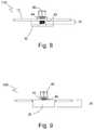
- FIG. 3is a top view of the clip shown in FIG. 1 .
- FIG. 4is a bottom view of the clip shown in FIG. 1 .
- FIG. 5is a top view of the clip of FIG. 1 showing the securing nut removed from the threaded post.
- FIG. 6is a right side plan view of the clip shown in FIG. 1 .
- FIG. 7is a cross-sectional, right side view of the clip shown in FIG. 4 .
- FIG. 8is a rear plan view of the clip shown in FIG. 1 .
- FIG. 9is a front plan view of the clip shown in FIG. 1 .
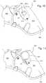
- FIG. 10is a perspective view of one embodiment of the present invention showing the removable clip attached to one embodiment of a holster where the removable clip has a D-ring.
- FIG. 11is a perspective view of one embodiment of the present invention showing the removable clip attached to the holster shown in FIG. 10 where the removable clip has a retractable lanyard.
- FIG. 12is a perspective view of one embodiment of the present invention showing the removable clip attached to another embodiment of a holster where the removable clip has a D-ring.
- FIG. 13is a perspective view of one embodiment of the present invention showing the removable clip attached to the holster shown in FIG. 12 where the removable clip has a retractable lanyard.
- FIG. 1shows one embodiment of the affixable and removable clip 100 of the present invention having a base portion 10 , a connector portion 20 , an anchor portion 30 , and a fastener 40 .
- Connector portion 20is between base portion 10 and anchor portion 30 forming a connecting bridge between base portion 10 and anchor portion 30 .
- Base portion 10is directly connected to connector portion 20 at a base connected end 11 .
- Anchor portion 30is directly connected to connector portion 20 at an anchor connected end 31 (not shown).
- Base portion 10also includes a first base aperture 50 .
- affixable and removable clip 100has a unitary clip body 5 having an approximate 180° bend in the clip body 5 where the clip body 5 forms the base portion 10 and the anchor portion 30 and where the bend forms the connector portion 20 .
- FIG. 2shows an exploded view of clip 100 showing fastener 40 having three distinct components 42 , 44 , 46 .
- fastener 40includes a rod 42 extending from anchor portion 30 through first base aperture 50 .
- the at least a rod 42is a threaded rod.
- a nut 46has internal threads that mate with the external threads of threaded rod 42 .
- a washer 44is disposed between nut 46 and base portion 10 .
- Base portion 10has a top base surface 10 a and base portion 10 further includes a first base portion 12 , a second base portion 14 , and a third base portion 16 .
- First base portion 12is an area of base portion 10 that includes base connected end 11 .
- Second base portion 14includes a majority of a middle area of base portion 10 .
- Third base portion 16is an area of base portion 10 that includes first base aperture 50 and a base terminal end 13 .
- second base portion 14includes a second base aperture 52 positioned near first base portion 12 .
- the size, shape, and location of second base aperture 52may vary to accommodate various tools, tasks, needs, and situations.
- One or more base apertures 53are optionally included as additional fixing locations.
- a third base aperture 53 ashown adjacent to and proximate to a corner 93 .
- the base portion 10is shown as having an approximately hexagonal shape with a plurality of corners 90 , 93 , 95 , 97 , and 99 .
- Anchor portion 30includes a first anchor portion 32 , a second anchor portion 34 , and a third anchor portion 36 that coincides with first base portion 12 , second base portion 14 , and third base portion 16 of base portion 10 .
- First anchor portion 32includes an anchor connected end 31 .
- Third anchor portion 36includes an anchor terminal end 33 .
- anchor portion 30has a first anchor aperture 60 and a second anchor aperture 62 .
- This embodimentshows first anchor aperture 60 positioned in third anchor portion 36 .
- Second anchor aperture 62is shown in second anchor portion 34 , and second anchor aperture 62 is shown aligned and co-axial with second base aperture 52 . It is contemplated that first anchor aperture 60 into which is pressed threaded rod 42 is not necessary if threaded rod 42 is attached in position to anchor portion 30 such as, for example, by welding or other bonding techniques including, but not limited to, adhesives and the like.
- each of the plurality of anchor apertures 60 and 62are circular. As with all of the apertures, the shape, size, and location may vary to accommodate various tools, tasks, needs, and situations. If a first anchor aperture 60 is included, then the diameter is typically between 0.0625 inch and 0.25 inch with a typical diameter of about 0.125 inch. The diameter of the second anchor aperture 62 is typically between 0.0625 inch and 0.75 inch with a typical diameter of about 0.375 inch. As with the plurality of apertures in base portion 30 , the apertures in anchor portion 30 also extend through the entirety of anchor portion 30 .
- anchor portion 30is shown as having an approximately quadrilateral shape.
- the present embodimentshows anchor 30 as having a generally rectangular shape.
- the length and width of base portion 10has a base length 72 and a base width 74 while anchor portion 30 has an anchor length 82 and an anchor width 84 .
- Base length 72can be compared to base width 74 to achieve a base ratio.
- a preferred base ratiois between approximately 1.5 and approximately 3.0 such that base length 72 is slightly longer than base width 74 up to approximately three times longer than base width 74 .
- base length 72is between 2 inches and 5 inches long with a typical length being approximately 3.75 inches.
- base width 74is between 1 inch and 3 inches long with a typical length being approximately 2 inches plus or minus 0.03125 inch.
- the anchor length 82can be compared to anchor width 84 to achieve an anchor ratio.
- a preferred anchor ratiois between approximately 2.0 and approximately 6.0 such that anchor length 82 is between approximately two times anchor width 84 and approximately six times anchor width 84 .
- anchor length 82is between 2 inches and 5 inches with a typical length of approximately 3.75 inches.
- anchor width 84is between 0.5 inch and 2 inches with a typical acceptable width of approximately 0.75 inch.
- Base length 72can be compared to anchor length 82 to achieve a base-anchor length ratio.
- a preferred base-anchor length ratiois between approximately 0.5 and approximately 2.0 such that the base length 72 is between approximately half anchor length 82 and approximately twice anchor length 82 .
- Base width 74can be compared to anchor width 84 to achieve a base-anchor width ratio.
- a preferred base-anchor width ratiois between approximately 1.5 and approximately 3.0 such that base width 74 is between approximately slightly larger than anchor width 84 and approximately three times anchor width 84 .
- FIG. 5is a right side plan view of clip 100 .
- threaded rod 42 of fastener 40is countersunk to the anchor portion 30 and nut 46 on threaded rod 42 prevents base portion 10 from moving away from anchor portion 30 such that threaded rod 42 is no longer disposed through first base aperture 50 .
- Washer 44is disposed between nut 46 and base portion 10 .
- FIG. 5also shows base portion 10 connected to anchor portion 30 via connector portion 20 . Additionally, this view shows base portion 10 being substantially parallel to anchor portion 30 .
- base portion 10has first base portion 12 , second base portion 14 , and third base portion 16 .
- Base portion 10has base connected end 11 and a base terminal end 17 opposite base connected end 11 .
- Base connected end 11is adjacent to first base portion 12 and base terminal end 17 is adjacent to third base portion 16 .
- anchor portion 30has first anchor portion 32 , second anchor portion 34 , and third anchor portion 36 .
- Anchor portion 30has anchor connected end 31 and an anchor terminal end 37 opposite anchor connected end 31 .
- Anchor connected end 31is adjacent anchor first portion 32
- anchor terminal end 37is adjacent anchor third portion 36 .
- FIG. 6is a bottom, plan view of removable clip 100 showing base portion 10 with first base aperture 50 , second base aperture 52 and a plurality of third base apertures 53 a , 53 b , 53 c , and 53 d extending through the base portion 10 .
- the plurality of third base apertures 53 a , 53 b , 53 c , and 53 dare proximate to corners 93 , 95 , 97 , and 99 , respectively.
- the fastener 40is shown as a bolt 42 .
- the clip 100 in FIG. 6is different from the clip 100 in FIG. 3 in that it shows fastener 40 with neither washer 44 nor nut 46 and only threaded rod 42 .
- base portion 10 around threaded rod 42 , first base aperture 50 through which threaded rod 42 protrudes, and anchor portion 30are all visible.
- first base aperture 50shows the first base aperture 50 as having an elongated shape.
- first base aperture 50has a length between 0.0625 inch and 0.75 inch with a typical length of about 0.375 inch.
- First base aperture 50has a width between 0.0625 inch and 0.75 inch with a typical width of about 0.25 inch.
- second base aperture 52is depicted as circular, it may have any shape desired. As shown in FIG. 6 , the circular diameter of second base aperture 52 is typically between 0.0625 inch and 0.25 inch with a typical length of about 0.125 inch.
- FIG. 7is a cross-sectional, right side view of the clip 100 .
- the at least a rod 42 of fastener 40extends transversely from anchor portion 30 and through first base aperture 50 in base portion 10 .
- Base portion 10 and anchor portion 30may have the same thickness or different thicknesses.
- clip 100is made from the same piece of sheet material, which material may be metal, plastic, wood, composites, and the like.
- the thicknessis typically in a range of about 0.03125 inch or greater; more typically in a range of about 0.03125 inch to about 0.125 inch but could be thicker if so desired. In any event, the thickness in not limiting.
- Connector portion 20determines the spacing between base portion 10 and anchor portion 30 . If connector portion 20 is a separate component, then its thickness determines the spacing between base portion 10 and anchor portion 30 . If connector portion 20 is part of the same sheet of material used to make base portion 10 and anchor portion 30 and if the material is bendable, then it is the size (i.e. radius) of the bend that determines the spacing between base portion 20 and anchor portion 30 . For example, a 0.125 radius bend will provide a small space between base portion 20 and anchor portion 30 than a 0.1875 radius. The space between the base portion 10 and the anchor portion 30 of clip 100 is configured to receive an intervening unit such as a belt, tool belt, tool holder, holster, or tool holster. The thickness and/or radius bend of connector portion 20 may be sized to accommodate any of these intervening units. Thus, in one embodiment of the present invention, the connector thickness (or radius bend) may be between 0.125 inch and 0.5 inch.
- FIG. 8is a front end view of clip 100 .
- FIG. 8shows the spacing 25 between base portion 10 and anchor portion 30 as well as threaded rod 42 , washer 44 and nut 46 . It is contemplated that, when clip 100 is attached to a tool holster, a hole is formed in the holster just large enough to permit threaded rod 42 to pass through the tool holster wall then through first base aperture 50 with final fixing to the holster wall by nut 46 being threaded onto threaded rod 42 .
- FIG. 9is a back end view of clip 100 showing connector portion 20 .
- Connector portion 20is shown here having a connector thickness 26 if connector portion 20 is the result of a radius bend of the material. If connector portion 20 is a separate piece, then thickness 26 would be equal to the spacing between base portion 10 and anchor portion 30 .
- Fastener 40is shown here as having threaded rod 42 , washer 44 , and nut 46 .
- FIG. 10is a perspective of clip 100 attached to one embodiment of a tool holster 400 .
- Holster 400has a tool pouch 402 formed by a pouch wall 404 being fixedly attached to a holster rear wall 406 .
- Pouch wall 404may be a separate piece from holster rear wall 406 or it may be a portion of rear wall 406 that is folded over and secured to holster rear wall 406 to form tool pouch 404 .
- Pouch wall 404is also considered an intervening structure 404 .
- clip 100is attached to tool holster 400 to form a combination 600 .
- This perspectiveshows the base portion 10 disposed on an outside surface 404 a of pouch wall 404 .
- Anchor portion 30is not visible as it is disposed on an inside surface 404 b (not shown) of pouch wall 404 .
- Connector portion 20is positioned adjacent a pouch top edge 404 c.
- fastener 40extends from anchor portion 30 through pouch wall 404 of tool holster 400 via an aperture formed in pouch wall 404 , securing to the base portion 10 .
- a D-ring 410is shown attached to the base portion 10 via a D-ring securing mechanism 408 that optionally permits the D-ring to pivot within the D-ring securing mechanism 408 .
- FIG. 11is a perspective view of another embodiment of the present invention.
- clip 100is attached to tool holster 400 in a similar way as described for FIG. 10 previously.
- the D-ringis replaced with a retractable lanyard 412 with a carabiner attachment 414 .
- FIGS. 12 and 13there is illustrated another embodiment of a tool holster 500 .
- Clip 100 of the present inventionis attached in a similar way to a tool pouch 504 .
- FIG. 12has a D-ring 410 attached to base portion 10 .
- FIG. 13has a retractable lanyard 412 with carabiner 414 attached to base portion 10 .
- the present inventionmay be constructed using many different types of material.
- the clip 100is made of a resilient and rigid or semi-rigid material, such as steel, iron, or other similar material.
- holster 400 , 500is made of a resilient and flexible or semi-flexible material such as ballistic nylon, polyester ballistic, leather, or other similar material.
- the clip 100may also be referred to as a clip body.
- the base portion 10may also be referred to as a first portion.
- the connector portion 20may also be referred to as a second portion, a bend portion, or a bend.
- the anchor portion 30may also be referred to as a third portion.
- the fastener 40may also be referred to as a fastening member.
- the tool holster 402may also be referred to as a holster, intervening unit, tool pouch, tool holder, or tool receptacle.
Landscapes
- Clamps And Clips (AREA)
Abstract
Description
Claims (19)
Priority Applications (2)
| Application Number | Priority Date | Filing Date | Title |
|---|---|---|---|
| US15/939,874US10716389B2 (en) | 2018-03-29 | 2018-03-29 | Affixable and removable clip |
| PCT/US2019/024592WO2019191434A1 (en) | 2018-03-29 | 2019-03-28 | Affixable and removable clip |
Applications Claiming Priority (1)
| Application Number | Priority Date | Filing Date | Title |
|---|---|---|---|
| US15/939,874US10716389B2 (en) | 2018-03-29 | 2018-03-29 | Affixable and removable clip |
Publications (2)
| Publication Number | Publication Date |
|---|---|
| US20190298042A1 US20190298042A1 (en) | 2019-10-03 |
| US10716389B2true US10716389B2 (en) | 2020-07-21 |
Family
ID=66102819
Family Applications (1)
| Application Number | Title | Priority Date | Filing Date |
|---|---|---|---|
| US15/939,874ActiveUS10716389B2 (en) | 2018-03-29 | 2018-03-29 | Affixable and removable clip |
Country Status (2)
| Country | Link |
|---|---|
| US (1) | US10716389B2 (en) |
| WO (1) | WO2019191434A1 (en) |
Citations (50)
| Publication number | Priority date | Publication date | Assignee | Title |
|---|---|---|---|---|
| US1977096A (en) | 1934-05-18 | 1934-10-16 | Gen Fireproofing Co | Tab construction for guide cards |
| US2420021A (en) | 1944-09-30 | 1947-05-06 | Gen Fireproofing Co | Tab for guide cards |
| US3934368A (en) | 1972-01-10 | 1976-01-27 | Donald David Fearing | Marking tag |
| USD268848S (en) | 1980-08-15 | 1983-05-03 | Laurel-Plastic Kurt Lorber | Tab for index cards |
| US4419794A (en) | 1981-10-05 | 1983-12-13 | Repco Incorporated | Portable fastening device |
| US4667374A (en) | 1981-12-04 | 1987-05-26 | Bianchi International | Holster clip |
| US4690315A (en) | 1984-09-26 | 1987-09-01 | Bianchi John E | Universal clip |
| US4828153A (en) | 1983-12-07 | 1989-05-09 | Motorola, Inc. | Detachable belt clip assembly |
| US4903745A (en) | 1987-09-22 | 1990-02-27 | Roman D Garry | Wallet with removable clip |
| USD314012S (en) | 1987-09-28 | 1991-01-22 | W. T. Rogers Company | Paper fastener |
| US5018653A (en)* | 1989-06-05 | 1991-05-28 | Shoemaker Randy R | Front draw handgun holster |
| US5341975A (en)* | 1993-05-24 | 1994-08-30 | Ilie Marinescu | Combination tool pouch and clip assembly |
| US5369846A (en) | 1993-05-04 | 1994-12-06 | Motorola, Inc. | Molded-in locking pin for belt clip and lanyard |
| USD353221S (en) | 1992-07-06 | 1994-12-06 | Scott Donald L | Flashlight clip for helmet |
| US5528770A (en) | 1994-06-06 | 1996-06-18 | Motorola Inc. | Self-locking belt clip for selective call receivers and method therefor |
| USD385417S (en) | 1996-08-30 | 1997-10-28 | Fossil, Inc. | Front pocket wallet |
| US5743451A (en)* | 1996-04-29 | 1998-04-28 | Kahn; Peter P. | Tool belt tool tote |
| USD412343S (en) | 1997-10-16 | 1999-07-27 | Laser Works, Inc. | Clip |
| USD429068S (en) | 1999-04-14 | 2000-08-08 | Mark John Kleinsmith | Combination card case with money clip and fabric insert |
| USD433715S (en) | 2000-02-14 | 2000-11-14 | Bartz Paul R | Clip card |
| US6189756B1 (en) | 1998-12-15 | 2001-02-20 | Mil-Tech, Inc. | Holster attachment device |
| USD465525S1 (en) | 2002-01-28 | 2002-11-12 | Micro Plastics, Inc. | Resilient grasping paper clip |
| US20020174521A1 (en)* | 2001-05-23 | 2002-11-28 | Vidal Michael A. | Hand tool lanyard system |
| US20030047575A1 (en) | 2001-09-07 | 2003-03-13 | Enkerlin E. Michael | Belt clip apparatus for portable electronic device |
| US20030141330A1 (en) | 2002-01-25 | 2003-07-31 | Mcdonald Kenneth J. | Defensive spray container holster |
| US6752299B2 (en) | 2001-12-07 | 2004-06-22 | Medtronic Minimed, Inc. | Rotational holster for an electronic device |
| US20050279787A1 (en)* | 2005-09-16 | 2005-12-22 | Dallco Marketing Services, Inc. | Holster and belt clip assembly for a box cutter |
| US6994238B2 (en) | 2003-01-17 | 2006-02-07 | Estabaya Romeo B | Screw gun holster |
| US20060175365A1 (en)* | 2005-02-08 | 2006-08-10 | Sandler Jeffrey L | Wearable tray system |
| USD541346S1 (en) | 2006-07-20 | 2007-04-24 | Lau Janet K | Integrated tabbed note and clip |
| USD559714S1 (en) | 2006-01-31 | 2008-01-15 | Taiwan Woei Shing Co., Ltd. | Belt clip for a tape measure |
| US7320420B2 (en) | 2004-02-12 | 2008-01-22 | Blackhawk Industries Product Group Unlimited Llc | Holster holder device |
| USD580981S1 (en) | 2007-01-18 | 2008-11-18 | Lau Janet K | Integrated tabbed note and clip |
| USD608093S1 (en) | 2009-04-24 | 2010-01-19 | Aaron W Moore | Card holder with clip |
| US7665684B2 (en) | 2001-08-10 | 2010-02-23 | Hammerhead Industries, Inc | Retracting tether for cell phones, pagers and PDA's |
| US20100243690A1 (en)* | 2007-10-30 | 2010-09-30 | Das Land Nordrhein-Westfalen, Innenministerium NRW Landesamt fur zentrale polizeiliche Dienste | Weapon Holster with Adjustable Draw Angle, in Particular for Hand Firearms and Latching Joint Unit, in Particular for Weapon Holsters |
| USD677193S1 (en) | 2011-11-16 | 2013-03-05 | Sumner MacDonald | Money clip |
| US8794560B2 (en) | 2001-08-10 | 2014-08-05 | Hammerhead Industries, Inc. | Retracting tether for cell phones, pagers, and PDAs |
| US9072364B2 (en)* | 2009-02-27 | 2015-07-07 | Wagic, Inc. | Item holder |
| US20150192388A1 (en)* | 2014-01-03 | 2015-07-09 | Tom Blach | Adapter for wearable carrying case |
| US20150238002A1 (en)* | 2014-02-21 | 2015-08-27 | L.F. Centennial Ltd. | Drill holster pouch |
| US9232850B2 (en)* | 2012-05-10 | 2016-01-12 | Darrell A. Moreau | Combination tool carrier and carrier securing lanyard |
| US9360276B1 (en) | 2013-05-13 | 2016-06-07 | Robert Michael Meek | Holster holder |
| US20160324301A1 (en) | 2015-05-07 | 2016-11-10 | Brian Babb | Belt-Mounted Can Holder |
| US20170005686A1 (en)* | 2015-07-01 | 2017-01-05 | iHIDE LLC | Holster system |
| WO2017065663A1 (en) | 2015-10-16 | 2017-04-20 | Luna Verktyg & Maskin Ab | Belt clip and belt clip arrangement |
| US20170290410A1 (en) | 2016-04-08 | 2017-10-12 | Scott Evans | Releasable retaining clip apparatus and method of use |
| US20170304605A1 (en) | 2014-10-10 | 2017-10-26 | Nxstage Medical, Inc. | Pinch Clamp Devices, Methods, and Systems |
| USD806529S1 (en) | 2013-03-15 | 2018-01-02 | Hubbell Incorporated | Clip-on bonding washer |
| US20190126018A1 (en) | 2010-03-19 | 2019-05-02 | University Of Washington | Body fluid drainage system |
- 2018
- 2018-03-29USUS15/939,874patent/US10716389B2/enactiveActive
- 2019
- 2019-03-28WOPCT/US2019/024592patent/WO2019191434A1/ennot_activeCeased
Patent Citations (51)
| Publication number | Priority date | Publication date | Assignee | Title |
|---|---|---|---|---|
| US1977096A (en) | 1934-05-18 | 1934-10-16 | Gen Fireproofing Co | Tab construction for guide cards |
| US2420021A (en) | 1944-09-30 | 1947-05-06 | Gen Fireproofing Co | Tab for guide cards |
| US3934368A (en) | 1972-01-10 | 1976-01-27 | Donald David Fearing | Marking tag |
| USD268848S (en) | 1980-08-15 | 1983-05-03 | Laurel-Plastic Kurt Lorber | Tab for index cards |
| US4419794A (en) | 1981-10-05 | 1983-12-13 | Repco Incorporated | Portable fastening device |
| US4667374A (en) | 1981-12-04 | 1987-05-26 | Bianchi International | Holster clip |
| US4828153A (en) | 1983-12-07 | 1989-05-09 | Motorola, Inc. | Detachable belt clip assembly |
| US4690315A (en) | 1984-09-26 | 1987-09-01 | Bianchi John E | Universal clip |
| US4903745A (en) | 1987-09-22 | 1990-02-27 | Roman D Garry | Wallet with removable clip |
| USD314012S (en) | 1987-09-28 | 1991-01-22 | W. T. Rogers Company | Paper fastener |
| US5018653A (en)* | 1989-06-05 | 1991-05-28 | Shoemaker Randy R | Front draw handgun holster |
| USD353221S (en) | 1992-07-06 | 1994-12-06 | Scott Donald L | Flashlight clip for helmet |
| US5369846A (en) | 1993-05-04 | 1994-12-06 | Motorola, Inc. | Molded-in locking pin for belt clip and lanyard |
| US5341975A (en)* | 1993-05-24 | 1994-08-30 | Ilie Marinescu | Combination tool pouch and clip assembly |
| US5528770A (en) | 1994-06-06 | 1996-06-18 | Motorola Inc. | Self-locking belt clip for selective call receivers and method therefor |
| US5743451A (en)* | 1996-04-29 | 1998-04-28 | Kahn; Peter P. | Tool belt tool tote |
| USD385417S (en) | 1996-08-30 | 1997-10-28 | Fossil, Inc. | Front pocket wallet |
| USD412343S (en) | 1997-10-16 | 1999-07-27 | Laser Works, Inc. | Clip |
| US6189756B1 (en) | 1998-12-15 | 2001-02-20 | Mil-Tech, Inc. | Holster attachment device |
| USD429068S (en) | 1999-04-14 | 2000-08-08 | Mark John Kleinsmith | Combination card case with money clip and fabric insert |
| USD433715S (en) | 2000-02-14 | 2000-11-14 | Bartz Paul R | Clip card |
| US20020174521A1 (en)* | 2001-05-23 | 2002-11-28 | Vidal Michael A. | Hand tool lanyard system |
| US8794560B2 (en) | 2001-08-10 | 2014-08-05 | Hammerhead Industries, Inc. | Retracting tether for cell phones, pagers, and PDAs |
| US7665684B2 (en) | 2001-08-10 | 2010-02-23 | Hammerhead Industries, Inc | Retracting tether for cell phones, pagers and PDA's |
| US20030047575A1 (en) | 2001-09-07 | 2003-03-13 | Enkerlin E. Michael | Belt clip apparatus for portable electronic device |
| US6752299B2 (en) | 2001-12-07 | 2004-06-22 | Medtronic Minimed, Inc. | Rotational holster for an electronic device |
| US20030141330A1 (en) | 2002-01-25 | 2003-07-31 | Mcdonald Kenneth J. | Defensive spray container holster |
| USD465525S1 (en) | 2002-01-28 | 2002-11-12 | Micro Plastics, Inc. | Resilient grasping paper clip |
| US6994238B2 (en) | 2003-01-17 | 2006-02-07 | Estabaya Romeo B | Screw gun holster |
| US7320420B2 (en) | 2004-02-12 | 2008-01-22 | Blackhawk Industries Product Group Unlimited Llc | Holster holder device |
| US20060175365A1 (en)* | 2005-02-08 | 2006-08-10 | Sandler Jeffrey L | Wearable tray system |
| US8322586B2 (en) | 2005-09-16 | 2012-12-04 | Adco Industries-Technologies, L.P. | Holster and belt clip assembly for a box cutter |
| US20050279787A1 (en)* | 2005-09-16 | 2005-12-22 | Dallco Marketing Services, Inc. | Holster and belt clip assembly for a box cutter |
| USD559714S1 (en) | 2006-01-31 | 2008-01-15 | Taiwan Woei Shing Co., Ltd. | Belt clip for a tape measure |
| USD541346S1 (en) | 2006-07-20 | 2007-04-24 | Lau Janet K | Integrated tabbed note and clip |
| USD580981S1 (en) | 2007-01-18 | 2008-11-18 | Lau Janet K | Integrated tabbed note and clip |
| US20100243690A1 (en)* | 2007-10-30 | 2010-09-30 | Das Land Nordrhein-Westfalen, Innenministerium NRW Landesamt fur zentrale polizeiliche Dienste | Weapon Holster with Adjustable Draw Angle, in Particular for Hand Firearms and Latching Joint Unit, in Particular for Weapon Holsters |
| US9072364B2 (en)* | 2009-02-27 | 2015-07-07 | Wagic, Inc. | Item holder |
| USD608093S1 (en) | 2009-04-24 | 2010-01-19 | Aaron W Moore | Card holder with clip |
| US20190126018A1 (en) | 2010-03-19 | 2019-05-02 | University Of Washington | Body fluid drainage system |
| USD677193S1 (en) | 2011-11-16 | 2013-03-05 | Sumner MacDonald | Money clip |
| US9232850B2 (en)* | 2012-05-10 | 2016-01-12 | Darrell A. Moreau | Combination tool carrier and carrier securing lanyard |
| USD806529S1 (en) | 2013-03-15 | 2018-01-02 | Hubbell Incorporated | Clip-on bonding washer |
| US9360276B1 (en) | 2013-05-13 | 2016-06-07 | Robert Michael Meek | Holster holder |
| US20150192388A1 (en)* | 2014-01-03 | 2015-07-09 | Tom Blach | Adapter for wearable carrying case |
| US20150238002A1 (en)* | 2014-02-21 | 2015-08-27 | L.F. Centennial Ltd. | Drill holster pouch |
| US20170304605A1 (en) | 2014-10-10 | 2017-10-26 | Nxstage Medical, Inc. | Pinch Clamp Devices, Methods, and Systems |
| US20160324301A1 (en) | 2015-05-07 | 2016-11-10 | Brian Babb | Belt-Mounted Can Holder |
| US20170005686A1 (en)* | 2015-07-01 | 2017-01-05 | iHIDE LLC | Holster system |
| WO2017065663A1 (en) | 2015-10-16 | 2017-04-20 | Luna Verktyg & Maskin Ab | Belt clip and belt clip arrangement |
| US20170290410A1 (en) | 2016-04-08 | 2017-10-12 | Scott Evans | Releasable retaining clip apparatus and method of use |
Non-Patent Citations (4)
| Title |
|---|
| 2019 EDC Gear Multi Function Sheath Scabbard Belt Clip, DHGate website, screen grab from May 13, 2019. |
| AA-10 Backpack Mountclip, Nikon website 2019, screen grab from May 13, 2019. |
| International Search Report from PCT/US2019/024592; 4 pages; Carols Nicolas; Jul. 12, 2019. |
| Milwaukee Adjustable Electricians Work Belt—48-22-8110, The Home Depot website 2019, screen grab from May 13, 2019. |
Also Published As
| Publication number | Publication date |
|---|---|
| US20190298042A1 (en) | 2019-10-03 |
| WO2019191434A1 (en) | 2019-10-03 |
Similar Documents
| Publication | Publication Date | Title |
|---|---|---|
| US8919629B2 (en) | Tool belt mountable device for retractable tool lanyards | |
| US6443342B1 (en) | Tool belt double tool tote | |
| US6015073A (en) | Safety utility belt | |
| US20100044405A1 (en) | Belt mountable holster for holding a power tool | |
| US6267277B1 (en) | Magnetic tool and equipment holder | |
| US20140097217A1 (en) | Tool Holding Device | |
| US5743451A (en) | Tool belt tool tote | |
| US8403132B2 (en) | Retractable tooling apparatus and tool pouch | |
| US7698970B1 (en) | Carabiner multi-tool | |
| US8650794B2 (en) | Firearm fastener | |
| US20040065709A1 (en) | Tool belt with spaced receiver blocks selectively receiving both complimentary tool holders and tools | |
| US7146651B1 (en) | Magnetic work apparel | |
| US20180070713A1 (en) | Drop prevention apparatus and system for hand tools | |
| US8016173B2 (en) | Bag for carrying concrete finishing tools | |
| US20120168472A1 (en) | Drop Prevention Tool Holsters | |
| US20020003155A1 (en) | Ambidextrous drill holster | |
| US20130299544A1 (en) | Combination tool carrier and carrier securing lanyard | |
| US20040050888A1 (en) | Universal tool support apparatus and methods | |
| US20060237498A1 (en) | Adaptable tool hook | |
| US12201208B1 (en) | Shield sling apparatus for shield support | |
| US10513027B2 (en) | Tool bag carrying handle with auxiliary loop | |
| US10716389B2 (en) | Affixable and removable clip | |
| US9662779B1 (en) | Ergonomic counter-balanced handled tool | |
| US20150192388A1 (en) | Adapter for wearable carrying case | |
| US20240191520A1 (en) | Tool organizer |
Legal Events
| Date | Code | Title | Description |
|---|---|---|---|
| AS | Assignment | Owner name:TY-FLOT, INC., NEW HAMPSHIRE Free format text:ASSIGNMENT OF ASSIGNORS INTEREST;ASSIGNORS:MOREAU, DARRELL A.;MOREAU, ANDRE M.;REEL/FRAME:045386/0548 Effective date:20180329 | |
| FEPP | Fee payment procedure | Free format text:ENTITY STATUS SET TO UNDISCOUNTED (ORIGINAL EVENT CODE: BIG.); ENTITY STATUS OF PATENT OWNER: SMALL ENTITY | |
| FEPP | Fee payment procedure | Free format text:ENTITY STATUS SET TO SMALL (ORIGINAL EVENT CODE: SMAL); ENTITY STATUS OF PATENT OWNER: SMALL ENTITY | |
| STPP | Information on status: patent application and granting procedure in general | Free format text:RESPONSE AFTER FINAL ACTION FORWARDED TO EXAMINER | |
| STPP | Information on status: patent application and granting procedure in general | Free format text:ADVISORY ACTION MAILED | |
| STPP | Information on status: patent application and granting procedure in general | Free format text:DOCKETED NEW CASE - READY FOR EXAMINATION | |
| AS | Assignment | Owner name:PURE SAFETY GROUP, INC., TEXAS Free format text:MERGER;ASSIGNOR:TY-FLOT, INC;REEL/FRAME:051041/0421 Effective date:20191001 | |
| STPP | Information on status: patent application and granting procedure in general | Free format text:NON FINAL ACTION MAILED | |
| STPP | Information on status: patent application and granting procedure in general | Free format text:RESPONSE TO NON-FINAL OFFICE ACTION ENTERED AND FORWARDED TO EXAMINER | |
| STPP | Information on status: patent application and granting procedure in general | Free format text:NOTICE OF ALLOWANCE MAILED -- APPLICATION RECEIVED IN OFFICE OF PUBLICATIONS | |
| STPP | Information on status: patent application and granting procedure in general | Free format text:PUBLICATIONS -- ISSUE FEE PAYMENT RECEIVED | |
| STCF | Information on status: patent grant | Free format text:PATENTED CASE | |
| AS | Assignment | Owner name:KEYBANK NATIONAL ASSOCIATION, OHIO Free format text:SECURITY INTEREST;ASSIGNOR:PURE SAFETY GROUP, INC.;REEL/FRAME:054899/0409 Effective date:20201223 | |
| AS | Assignment | Owner name:PURE SAFETY GROUP, INC., TEXAS Free format text:RELEASE BY SECURED PARTY;ASSIGNOR:KEYBANK NATIONAL ASSOCIATION;REEL/FRAME:056527/0428 Effective date:20210607 | |
| AS | Assignment | Owner name:JPMORGAN CHASE BANK, N.A., AS ADMINISTRATIVE AGENT, ILLINOIS Free format text:SECURITY INTEREST;ASSIGNOR:PURE SAFETY GROUP, INC.;REEL/FRAME:056684/0090 Effective date:20210607 | |
| MAFP | Maintenance fee payment | Free format text:PAYMENT OF MAINTENANCE FEE, 4TH YR, SMALL ENTITY (ORIGINAL EVENT CODE: M2551); ENTITY STATUS OF PATENT OWNER: SMALL ENTITY Year of fee payment:4 | |
| AS | Assignment | Owner name:PURE SAFETY GROUP, INC., TEXAS Free format text:RELEASE BY SECURED PARTY;ASSIGNOR:JPMORGAN CHASE BANK, N.A., AS ADMINISTRATIVE AGENT;REEL/FRAME:069873/0853 Effective date:20250103 | |
| AS | Assignment | Owner name:SIENA LENDING GROUP LLC, CONNECTICUT Free format text:SECURITY INTEREST;ASSIGNOR:PURE SAFETY GROUP, INC.;REEL/FRAME:070205/0813 Effective date:20250103 |