US10716199B2 - Devices for gas cooling plasma arc torches and related systems and methods - Google Patents
Devices for gas cooling plasma arc torches and related systems and methodsDownload PDFInfo
- Publication number
- US10716199B2 US10716199B2US14/091,016US201314091016AUS10716199B2US 10716199 B2US10716199 B2US 10716199B2US 201314091016 AUS201314091016 AUS 201314091016AUS 10716199 B2US10716199 B2US 10716199B2
- Authority
- US
- United States
- Prior art keywords
- shield
- flow
- nozzle
- gas
- flange
- Prior art date
- Legal status (The legal status is an assumption and is not a legal conclusion. Google has not performed a legal analysis and makes no representation as to the accuracy of the status listed.)
- Active, expires
Links
Images


Classifications
- H—ELECTRICITY
- H05—ELECTRIC TECHNIQUES NOT OTHERWISE PROVIDED FOR
- H05H—PLASMA TECHNIQUE; PRODUCTION OF ACCELERATED ELECTRICALLY-CHARGED PARTICLES OR OF NEUTRONS; PRODUCTION OR ACCELERATION OF NEUTRAL MOLECULAR OR ATOMIC BEAMS
- H05H1/00—Generating plasma; Handling plasma
- H05H1/24—Generating plasma
- H05H1/26—Plasma torches
- H05H1/28—Cooling arrangements
- B—PERFORMING OPERATIONS; TRANSPORTING
- B23—MACHINE TOOLS; METAL-WORKING NOT OTHERWISE PROVIDED FOR
- B23K—SOLDERING OR UNSOLDERING; WELDING; CLADDING OR PLATING BY SOLDERING OR WELDING; CUTTING BY APPLYING HEAT LOCALLY, e.g. FLAME CUTTING; WORKING BY LASER BEAM
- B23K9/00—Arc welding or cutting
- B23K9/24—Features related to electrodes
- B23K9/28—Supporting devices for electrodes
- B23K9/285—Cooled electrode holders
- H—ELECTRICITY
- H05—ELECTRIC TECHNIQUES NOT OTHERWISE PROVIDED FOR
- H05H—PLASMA TECHNIQUE; PRODUCTION OF ACCELERATED ELECTRICALLY-CHARGED PARTICLES OR OF NEUTRONS; PRODUCTION OR ACCELERATION OF NEUTRAL MOLECULAR OR ATOMIC BEAMS
- H05H1/00—Generating plasma; Handling plasma
- H05H1/24—Generating plasma
- H05H1/26—Plasma torches
- H05H1/32—Plasma torches using an arc
- H05H1/34—Details, e.g. electrodes, nozzles
- H05H1/3405—Arrangements for stabilising or constricting the arc, e.g. by an additional gas flow
- H—ELECTRICITY
- H05—ELECTRIC TECHNIQUES NOT OTHERWISE PROVIDED FOR
- H05H—PLASMA TECHNIQUE; PRODUCTION OF ACCELERATED ELECTRICALLY-CHARGED PARTICLES OR OF NEUTRONS; PRODUCTION OR ACCELERATION OF NEUTRAL MOLECULAR OR ATOMIC BEAMS
- H05H1/00—Generating plasma; Handling plasma
- H05H1/24—Generating plasma
- H05H1/26—Plasma torches
- H05H1/32—Plasma torches using an arc
- H05H1/34—Details, e.g. electrodes, nozzles
- H05H1/3457—Nozzle protection devices
- H05H2001/3457—
Definitions
- This disclosurerelates generally to thermal cutting torches (e.g., plasma arc torches), and more specifically to devices for gas cooling plasma arc torches and to related systems and methods.
- thermal cutting torchese.g., plasma arc torches
- Basic components of modern conventional plasma arc torchesinclude a torch body, an electrode (e.g., cathode) mounted within the body, a nozzle (e.g., anode) with a central orifice that can produce a pilot arc to the electrode to initiate a plasma arc in a flow of a suitable gas (e.g. air, nitrogen or oxygen) and associated electrical connections and passages for cooling, and arc control fluids.
- a suitable gase.g. air, nitrogen or oxygen
- Generation of the pilot arcmay be by means of a high frequency, high voltage signal coupled to a DC power supply and the plasma arc torch, or any of a variety of contact starting methods.
- a shieldis mounted to the torch body to prevent metal that is spattered from the workpiece (sometimes referred to as slag) during processing from accumulating on torch parts (e.g., the nozzle or the electrode).
- the shieldincludes a shield exit portion (also called a shield orifice) that permits the plasma jet to pass therethrough.
- the shieldcan be mounted co-axially with respect to the nozzle such that the plasma exit portion is aligned with the shield exit portion.
- Cooling capacityhas been a limitation of previous designs relating to plasma arc torches.
- previous designshave required the use of cooling mediums other than or in addition to a gas (e.g., cooling water or liquid) for torches that operate at high (e.g., 100 or 200 Amps, or more) current levels.
- Most of these cooling methodscan require cooling systems external to the torch (e.g., which can include water supplies, reservoirs, heat exchange equipment, supply pumps, etc.).
- External cooling systemscan increase the associated equipment expense, can require more maintenance, be vulnerable to spills, and in some cases, can require disposal of the cooling medium.
- the issue of cooling the plasma arc torchis more acute for higher current systems, as higher current systems can generate more heat and have larger cooling demands.
- commercially available plasma arc torch cutting systems operating at more than about 100 amperestypically utilize cooling systems using a liquid coolant (e.g., water or glycol).
- a liquid coolante.g., water or glycol
- a nozzle for a gas-cooled plasma arc torchcan include a hollow generally cylindrical body having a first end and a second end that define a longitudinal axis, the second end of the body defining a nozzle exit orifice; a gas channel formed in the first end between an interior wall and an exterior wall of the cylindrical body, the gas channel directing a gas flow circumferentially about at least a portion of the body; an inlet passage formed substantially through a radial surface of the exterior wall and fluidly connected to the gas channel; and an outlet passage at least substantially aligned with the longitudinal axis and fluidly connected to the gas channel.
- Embodimentscan include one or more of the following features.
- the inlet passagecan include an inlet port formed through a radial surface of the body.
- the outlet passagecan include an outlet port formed through a second exterior radial surface of the body between the second end of the nozzle and the inlet port.
- the nozzleincludes a plurality of (e.g., multiple) inlet passages. In some cases, a radial angle between respective inlet passages is about 120 degrees. In some embodiments, the nozzle includes a plurality of outlet passages. In some cases, a radial angle between respective outlet passages is about 120 degrees. In some embodiments, the nozzle includes a plurality of inlet passages and a plurality of outlet passages. In some cases, the inlet passages are radially offset from the outlet passages.
- the circumferential gas flow along the gas channelextends about an entire circumference of the nozzle.
- a portion of the nozzle wallsare configured to mate with an exterior surface of a swirl ring.
- the swirl ringforms a portion of the gas channel.
- a nozzle for a gas-cooled plasma arc torchcan include a hollow generally cylindrical body having a first end and a second end that define a longitudinal axis, the second end of the body defining a nozzle exit orifice; a plenum region defined within the body and directing a plasma gas; a cooling gas channel formed in the first end between an interior wall and an exterior wall of the cylindrical body, the cooling gas channel isolating a cooling gas from the plasma gas; a substantially radially oriented inlet passage fluidly connected to the gas channel; and a substantially longitudinally oriented outlet passage fluidly connected to the gas channel.
- Embodimentscan include one or more of the following features.
- the radially oriented inlet passagealso includes an inlet port formed through a radial surface of the body.
- the longitudinally oriented outlet passagesalso include an outlet port formed through a radial surface of the body between the second end of the nozzle and the inlet port.
- the nozzleincludes a plurality of radially oriented inlet passages. In some cases, a radial angle between respective inlet passages is about 120 degrees. In some embodiments, the nozzle also includes a plurality of outlet passages. In some cases, a radial angle between respective outlet passages is about 120 degrees. In some embodiments, the nozzle includes a plurality of inlet passages and a plurality of outlet passages. In some cases, the inlet passages are radially offset from the outlet passages.
- the circumferential gas flow along the gas channelextends about an entire circumference of the nozzle.
- a portion of the nozzle wallsare configured to mate with an exterior surface of a swirl ring.
- the swirl ringcan form a portion of the gas channel.
- the plasma gas and the cooling gascombine at the exit orifice of the nozzle.
- a method for cooling a nozzle for a plasma arc torchcan include providing the nozzle having a hollow body with a first end and a second end, the second end of the body defining a nozzle exit orifice, a gas channel formed in the first end of the body, a substantially radially oriented inlet passage fluidly connected to the gas channel, and a substantially longitudinally oriented outlet passage fluidly connected to the gas channel; flowing the cooling gas through the inlet passage into the gas channel; directing the cooling gas along the gas channel; and discharging the cooling gas from the gas channel to the outlet passage.
- a nozzle for a gas-cooled plasma arc torchcan include a body having a first end and a second end that define a longitudinal axis; a plenum region substantially formed within the body, the plenum region extending from the first end of the body and configured to receive a plasma gas flow; an exit orifice located at the second end of the body and oriented substantially coaxially with the longitudinal axis, the exit orifice fluidly connected to the plenum region; and a feature on an outer surface of the body configured to increase cooling by receiving a cooling gas flow flowing at high velocity generally in a direction of the longitudinal axis along a length of the body, an impingement surface of the feature configured to receive the cooling gas flow at a substantially perpendicular direction relative to the impingement surface and to redirect the cooling gas flow to promote cooling and uniform shield flow.
- Embodimentscan include one or more of the following features.
- the featureis disposed about a circumference of the outer surface of the nozzle body.
- the substantially perpendicular directioncan be between about 45 degrees and 90 degrees relative to the impingement surface.
- a cross section of the impingement surface of the featureincludes a substantially planar surface that is arranged substantially perpendicularly to the cooling gas flow. In some embodiments, the impingement surface of the feature includes a substantially conical surface. In some embodiments, the feature is positioned on the nozzle adjacent a corresponding feature of a shield component. In some cases, the corresponding feature is a mixing chamber.
- the high velocityis at least 300 meters per second.
- the featureincludes at least a portion of a chamber of sufficient size to increase a flow uniformity of the cooling gas by performing as a buffering chamber to reduce cooling gas flow transients.
- the chamberextends about a circumference of the outer surface of the nozzle.
- the nozzleincludes a sharp corner adjacent the impingement surface to generate turbulence in the cooling gas flow.
- a nozzle cooling system for a plasma arc torchcan include a nozzle having a body with a first end and a second end that define a longitudinal axis, a plenum region substantially formed within the body, the plenum region extending from the first end of the body and configured to receive a plasma gas flow, an exit orifice located at the second end of the body and oriented substantially coaxially with the longitudinal axis, the exit orifice fluidly connected to the plenum region, and a feature on an outer surface of the body configured to increase cooling by receiving a cooling gas flow flowing at high velocity generally in a direction of the longitudinal axis along a length of the body, an impingement surface of the feature configured to receive the cooling gas flow at a substantially perpendicular direction relative to the impingement surface and to redirect the cooling gas flow to promote cooling and uniform shield flow; and a nozzle retaining cap comprising a generally cylindrical body and a securing flange, the securing flange of the retaining cap including a
- Embodimentscan include one or more of the following features.
- the nozzle retaining capcan include about 10 shield gas supply ports.
- a nozzle-shield cooling systemcan include a nozzle having a body with a first end and a second end that define a longitudinal axis; a plenum region substantially formed within the body, the plenum region extending from the first end of the body and configured to receive a plasma gas flow; an exit orifice located at the second end of the body and oriented substantially coaxially with the longitudinal axis, the exit orifice fluidly connected to the plenum region; and a feature on an outer surface of the body configured to increase cooling by receiving a cooling gas flow flowing at high velocity generally in a direction of the longitudinal axis along a length of the body, an impingement surface of the feature configured to receive the cooling gas flow at a substantially perpendicular direction relative to the impingement surface and to redirect the cooling gas flow to promote cooling and uniform shield flow; and a shield for the plasma arc torch including a generally conical body and an end face having a shield exit orifice, an interior surface of the shield defining a mixing chamber at
- Embodimentscan include one or more of the following features.
- the mixing chamber and inlet edgeextend about a circumference of the interior surface of the shield. In some embodiments, a profile of the inlet edge is an acute angle. In some embodiments, the inlet edge extends toward the first end of the nozzle body. The inlet edge can also extend toward the second end of the nozzle body.
- the shieldhas at least two inlet edge features.
- the mixing chamberhas a bulbous cross section. In some embodiments, the mixing chamber is of sufficient volume to increase a flow uniformity of the cooling gas by performing as a buffering chamber to reduce cooling gas flow transients.
- a shield for an air-cooled plasma arc torchcan include a body having a proximal end configured to mate with a torch body of the plasma arc torch and a distal end; an exit orifice formed in the distal end of the body; and an interior of the shield defining a shield flow surface that forms a portion of a shield gas flow channel, the shield gas flow channel directing a flow of shield gas along the interior shield flow surface in a flow direction from the proximal end to the exit orifice at the distal end of the body, the interior of the shield also defining a flow feature disposed on the interior shield flow surface, the flow feature formed circumferentially about an interior of the body between the proximal end and the exit orifice, the flow feature configured to reverse the flow direction of the shield gas flow within the shield gas flow channel.
- Embodimentscan include one or more of the following features.
- the interior shield flow surfaceincludes a mixing chamber formed circumferentially about the body at a portion of the shield gas flow channel adjacent an impingement feature of a corresponding nozzle, the mixing chamber includes an inlet edge positioned to direct the shield gas into the mixing chamber.
- the flow featurealso defines a recombination region, the recombination region between the exit orifice and the mixing chamber.
- the flow featuredefines a recombination region, the recombination region between a set of shield vent ports and the exit orifice.
- the flow featurecan include a protuberance and a recess that cooperate to reverse the flow direction.
- the protuberanceis adjacent the recess.
- the flow featureincludes a protuberance, such that the protuberance is a ridge that extends around a circumference of the interior shield flow surface.
- the flow featureincludes a recess, such that the recess is a groove that extends around a circumference of the interior shield flow surface.
- the flow featureincludes a protuberance, such that the protuberance is between the recess and the exit orifice. The flow feature can be disposed on a conical portion of the shield body.
- the flow featurecan be disposed on an end face of the distal end of the shield body.
- the flow featurecan include a protuberance, such that the protuberance is disposed at a location on the interior shield flow surface that corresponds to a complementary feature of an adjacent torch nozzle when the shield is attached to the plasma arc torch.
- the complementary feature of the nozzlecan be a ridge.
- a cross section of the protuberance and the complementary feature of the nozzlewhen assembled, can both be parallel to a longitudinal axis of a torch body of the plasma arc torch.
- the protuberance and the complementary feature of the nozzleform a tortured flow path.
- a nozzle for an air-cooled plasma arc torchcan include a body having a proximal end configured to mate with a torch body of the plasma arc torch and a distal end; an orifice formed in the distal end of the body; and an exterior of the nozzle comprising a nozzle flow surface that forms a portion of a shield gas flow channel, the shield gas flow channel directing a flow of shield gas along the exterior nozzle flow surface in a flow direction from the proximal end to the orifice at the distal end of the body, the exterior of the nozzle also having a flow feature disposed on the exterior nozzle flow surface, the flow feature formed circumferentially about an exterior of the body between the proximal end and the orifice, the flow feature configured to reverse the flow direction of the shield gas flow within the shield gas flow channel.
- Embodimentscan include one or more of the following features.
- the nozzleincludes a feature on the exterior nozzle flow surface of the nozzle body configured to increase cooling of the body by receiving at least a portion of the shield gas flow flowing at high velocity generally in a direction of a longitudinal axis of the nozzle body and along a length of the body, an impingement surface of the feature configured to receive the at least a portion of the cooling gas flow at a substantially perpendicular direction relative to the impingement surface and to redirect the cooling gas flow to promote cooling and uniform shield flow.
- the exterior nozzle flow surfaceincludes a mixing chamber formed circumferentially about the body at a portion of the shield gas flow channel that is adjacent the impingement feature.
- the flow featurecan include a protuberance and a recess that cooperate to reverse the flow direction.
- the protuberanceis adjacent the recess.
- the flow featureincludes a protuberance, such that the protuberance is a ridge that extends around a circumference of the exterior nozzle flow surface.
- the flow featurecan include a recess, such that the recess is a groove that extends around a circumference of the exterior nozzle flow surface.
- the flow featurecan include a protuberance, such that the protuberance is between the recess and the orifice.
- the flow featurecan be disposed on a conical portion of the nozzle body.
- the flow featurecan be disposed on an end face of the distal end of the nozzle body.
- the flow featurecan include a protuberance, such that the protuberance is disposed at a location on the exterior nozzle flow surface that corresponds to a complementary feature of an adjacent torch shield when the nozzle is attached to the plasma arc torch.
- the complementary feature of the shieldcan be a ridge.
- a consumable set for an air-cooled plasma arc torch systemcan include a shield including a shield body having a proximal end configured to mate with a torch body of the plasma arc torch and a distal end; an exit orifice formed in the distal end of the body; and an interior of the shield having a shield flow surface that forms a portion of a shield gas flow channel, the shield gas flow channel directing a flow of shield gas along the interior shield flow surface in a flow direction from the proximal end to the exit orifice at the distal end of the body, the interior of the shield also having a flow feature disposed on the interior shield flow surface, the flow feature formed circumferentially about an interior of the body between the proximal end and the exit orifice, the flow feature configured to reverse the flow direction of the shield gas flow within the shield gas flow channel; and a nozzle formed of an electrically conductive material including a nozzle body having a first end and a second end that define a longitudinal axis; a nozzle formed of
- Embodimentscan include one or more of the following features.
- the interior shield flow surfacefurther can include a mixing chamber formed circumferentially about the shield body at a portion of the shield gas flow channel adjacent the impingement feature.
- a method for cooling a nozzle of an air-cooled plasma arc torchcan include supplying a shield gas at a substantially perpendicular angle to an exterior feature of the nozzle; redirecting the shield gas from the exterior feature of the nozzle to a mixing chamber adjacent the feature; and flowing the shield gas from the mixing chamber along a shield gas flow channel to an exit orifice of the shield, the shield gas flow channel at least partially defined by an exterior surface of the nozzle.
- Embodimentscan include one or more of the following features.
- the methodcan also include flowing the shield gas from the mixing chamber through a recombination region disposed between the nozzle and the shield to produce a substantially uniform shield gas flow at the exit orifice, the recombination region comprising at least one flow-redirecting member.
- the recombination regioncan be downstream of the mixing chamber and include a baffle on an interior surface of the shield and a baffle on an exterior surface of the nozzle.
- the shield baffle and the nozzle baffleare adjacent each other when the shield and the nozzle are assembled to the torch.
- At least a portion of the mixing chambercan be disposed on the exterior surface of the nozzle. In some embodiments, at least a portion of the mixing chamber can be disposed on an interior surface of an adjacent shield. In some embodiments, at least a portion of the mixing chamber can be disposed on the exterior surface of the nozzle and at least a portion of the mixing chamber can be disposed on an interior surface of an adjacent shield.
- a method for providing a uniform shield gas flow for an air-cooled plasma arc torchcan include supplying a shield gas to a shield gas flow channel defined by an exterior surface of a nozzle and an interior surface of a shield; flowing the shield gas along the shield gas flow channel; reversing the flow of the shield gas along the shield gas flow channel using a recombination region, the recombination region comprising at least one flow reversing member; and flowing the shield gas from the mixing region to an exit orifice of the shield, thereby producing a substantially uniform shield gas flow at the exit orifice.
- a nozzle for a gas-cooled plasma arc torchcan include a nozzle body having a proximal end and a distal end that define a nozzle body length and a longitudinal axis, the body including; an exit orifice defined by the distal end of the nozzle body; a plenum within the nozzle body, the plenum extending from the proximal end of the nozzle body to a plenum floor, a distance from the plenum floor to the distal end defining a plenum floor thickness, and a distance from the plenum floor to the proximal end of the nozzle body defining a proximal end height; and a bore extending from the plenum floor to the exit orifice, the bore having a bore length and a bore width, wherein the nozzle body has a nozzle width in a direction transverse to the longitudinal axis, wherein the nozzle body length is greater than the nozzle width, and wherein a ratio of the proximal end
- Embodimentscan include one or more of the following features.
- the nozzlecan also include a body flange at the proximal end of the nozzle body, an overall length of the nozzle defined by a distance from a proximal end of the nozzle body flange to an end face at the distal end of the nozzle, such that the overall length of the nozzle is greater than the nozzle body length.
- the body flangeextends about 0.05 to about 0.5 inches above the nozzle plenum.
- the proximal end heightincludes the body flange.
- the length of the borecorresponds to the plenum floor thickness.
- the borecan include a chamfer or a counter bore.
- the width of the borecan vary along its length.
- the borecan have a chamfer or a counter bore at each end of its length.
- the exit orificecan be at an end face of the nozzle.
- a ratio of the length of the bore to the nozzle body lengthcan be greater than about 0.32.
- a side wall thickness of the plenumcan be between an inside diameter of the plenum and an outer diameter of the plenum, and the ratio of the plenum side wall thickness to the width of the nozzle body can be about 0.15 to about 0.19.
- a side wall of the plenumcan include one or more cooling gas passages.
- the nozzlecan be sized to operate in the plasma arc torch at a current flow of at least 100 amps. In some embodiments, the nozzle can operate at a current to nozzle body length ratio of greater than 170 amps per inch.
- the ratio of the proximal end height to the plenum floor thicknesscan be less than about 1.4.
- a nozzle for an air-cooled plasma arc torchconfigured to operate above 100 amps can include a nozzle body having a distal portion defining a conduit substantially aligned with a longitudinal axis of the nozzle body, the conduit having a conduit length and shaped to direct a plasma gas flow; and a proximal portion coupled to the distal portion and having a proximal portion length, the proximal portion defining a plenum fluidly connected to the conduit, wherein a ratio of a length of the proximal portion to the conduit length can be less than about 2.0, and wherein the nozzle can be configured to permit operation at a current to nozzle body length ratio of greater than about 170 amps/inch.
- Embodimentscan include one or more of the following features.
- the nozzlecan include a body flange at a proximal end of the proximal portion of the nozzle body, an overall length of the nozzle defined by a distance from a proximal end of the nozzle body flange to an end face at the distal end of the nozzle, such that the overall length of the nozzle is greater the nozzle body length.
- the body flange of the nozzlecan include a flow channel.
- the conduit lengthcan correspond to a plenum floor thickness.
- the conduitcan include a chamfer or a counter bore.
- a width of the conduitcan vary along the conduit length.
- the conduitcan have a chamfer or a counter bore at each end of its length.
- a side wall thickness of the plenumcan be between an inside diameter of the plenum and an outer diameter of the plenum, and the ratio of the plenum side wall thickness to the width of the nozzle body can be about 0.15 to about 0.19.
- a side wall of the plenumcan include one or more cooling gas passages.
- the cooling gas passagescan be sized to permit the nozzle to operate in the plasma arc torch at a current flow of at least 100 amps. In some embodiments, the cooling gas passages can be sized to permit operation of the nozzle at a current to nozzle body length ratio of greater than 170 amps per inch.
- the ratio of the length of the proximal portion to the conduit lengthcan be less than about 1.4.
- Embodiments described hereincan have one or more of the following advantages.
- consumable componentse.g., nozzles
- a gas cooling channel formed between an inner (e.g., interior) wall and an outer (e.g., exterior) wallcan have greater cooling capabilities than some other consumable components that do not have similar gas channels.
- the increased cooling capabilitiesresult in part because additional cooling gas contact surface area is created within the nozzle through which heat can transfer and be carried away by the cooling gas.
- Increased cooling capabilitiescan result in better cutting performance, for example, by helping to create more stable plasma arcs and longer usable consumable life. Longer usable consumable life can lead to fewer consumable replacements needed, which can result in reduced costs and system downtime.
- forming the gas cooling channel within an outer wall of the nozzlecan provide for better separation (e.g., isolation) of the gas cooling channel from the plasma gas flow path, which can result in increased cooling capabilities without substantially interfering with delivery and/or control of the plasma gas.
- gas cooling channelshaving one or more horizontal (i.e., substantially perpendicular to a longitudinal axis of the nozzle) inlets and one or more vertical (i.e., substantially longitudinally) outlets which may be circumferentially offset from the horizontal inlets, can help to provide impinging gas flows onto different surfaces of the nozzle.
- the impinging flowcan help to create turbulent flows for additional increased cooling.
- nozzles described herein having a feature arranged along its outer surface that defines an impingement surface to receive a cooling gas flowcan have increased nozzle cooling capabilities relative to some other conventional nozzles.
- the impingement surfacecan be angled relative to one or more other outer surfaces of the nozzle so that the cooling gas flow contacts (i.e., impinges) the impingement surface substantially perpendicularly relative to the impingement surface, which can result in increased cooling capabilities.
- the angled impingement surfaceis typically angled to be arranged substantially perpendicularly to an angled cooling gas flow channel defined within a nozzle retaining cap that provides a cooling gas flow.
- the arrangement of the angled impingement surface within a mixing channelcan help to generate high velocity gas flow mixing, for example, in part due to the substantially perpendicular impingement of the gas flow onto the impingement surface, which can increase cooling capabilities relative to some other conventional nozzles without such features.
- the feature and the impingement surfacehelp to create a turbulent flow within the mixing channel which further aids cooling.
- the mixing channelcan help to mix and distribute (e.g., evenly distribute) the flow of the cooling shield gas around the nozzle so that it can be delivered more evenly. More evenly delivered shield gas can create a more stable plasma arc, which can result in improved cut speed and consistency.
- features of the nozzlecan work in combination with corresponding features (e.g., grooves or flanges) formed on other consumable components, such as a shield, to alter (e.g., disturb, perturb, and/or partially block, redirect, or redistribute) the flow of shield gas flowing between the nozzle and the shield.
- some nozzlescan include a recess in which a flange of a shield can be partially disposed during use. The configuration of the flange disposed within a recess can cause the flowing shield gas to be temporarily redirected (e.g., directed away from and then back towards) the distal end of the torch.
- Such redirectioncan help to mix and distribute the shield gas flow annularly around the shield exit orifice so that the distribution of shield gas exiting the torch can be more evenly distributed than in some other conventional torch systems. More evenly distributed shield gas can be useful in helping to create a more stable plasma arc by reducing or limiting inconsistently varying gas flows around the plasma arc.
- other features described herein, such as the complementary mixing channel formed by features and surfaces of the nozzle and/or shieldcan also help to receive gas flow delivered from multiple discrete channels and distribute the gas flow circumferentially around the nozzle to help create a more evenly distributed gas flow and a more uniform plasma arc.
- nozzles as described hereinthat are designed, proportioned, and constructed to be shorter (i.e., longitudinally shorter proximal end height), wider (i.e., having a thicker nozzle tip (e.g., a wider or larger end face) and/or thicker plenum side walls), and/or have a longer bore (i.e., a thicker distal region) can produce greater cooling effects relative to some other conventional nozzles that lack such modified features.
- these proportionsresult in a nozzle having increased tip mass concentrated at the distal region (e.g., increased tip mass to volume ratios relative to the rest of the nozzle), which can result in increased cooling capacity.
- increased material mass and volume located at the distal tip of the nozzleespecially increased material positioned radially surrounding the exit orifice can provide greater heat transfer paths through which heat can travel outwardly within the nozzle and proximally away from the torch tip.
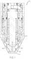
- FIG. 1is a cross sectional view of an example plasma arc torch defining various gas flow channels used to deliver shield or cooling gas to the torch tip.
- FIG. 2is a sectioned view of an example nozzle for a plasma arc torch that includes a gas channel defined between an interior wall and an exterior wall for directing gas flow circumferentially around the body of the nozzle.
- FIG. 3is a cross sectional view of a plasma arc torch having a nozzle cooling system and a flow distribution system defined by features and elements formed along its nozzle and shield.
- FIG. 4is an enlarged cross sectional view of the nozzle cooling system of FIG. 3 illustrating an example cooling gas flow within and around the nozzle.
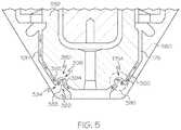
- FIG. 5is an enlarged cross sectional view of the flow distribution system of FIG. 3 illustrating features formed along the nozzle and shield to redirect and substantially uniformly distribute the shield gas flow annularly around the nozzle.
- FIG. 5Ais an enlarged cross sectional view of another example flow distribution system illustrating features formed along the nozzle and shield to redirect and substantially uniformly distribute the shield gas flow annularly around the nozzle.
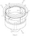
- FIG. 6is a cross sectional view of an example nozzle for a plasma arc torch having a wider end face and distal end region to distribute heat and increase nozzle cooling.
- FIG. 7is a simulated gas flow model depicting gas flow into and out of the gas channel of FIG. 2 .
- nozzles and/or shieldscan include corresponding features (e.g., grooves or flanges) to alter (e.g., redirect, or redistribute) the flow of shield gas flowing between the nozzle and the shield.
- corresponding featurese.g., grooves or flanges
- alteration of the shield gas flowcan help to distribute the shield gas flow around the nozzle to help produce a more stable and concentrated plasma arc.
- FIG. 1illustrates an example plasma torch 50 that can be used with the various aspects and embodiments of the plasma arc torch cooling systems, devices, and methods described herein.
- the plasma torch 50can include an electrode 60 , a nozzle 100 , and a shield 150 .
- the torch 50can be in electrical communication (e.g., using a current-carrying cable (not shown)) with a power supply (not shown) and receive electrical current from the power supply.
- the electrical current received from the power supplyis transferred, through a current path, to the electrode 60 toward the nozzle 100 .
- gase.g., plasma gas
- the plasma gascan be accelerated (e.g., the plasma gas can be heated, which reduces density of the gas as the plasma is formed, which increases its volume and velocity) within the plasma plenum 80 to generate a plasma stream via a plasma arc created between the electrode 60 and the nozzle 100 .
- nozzle temperature during the usecan have a significant impact on electrode life.
- electrode and nozzle lifecan be low relative to lower current air-cooled plasma arc cutting systems.
- increased coolingcan be a useful technique in extending or prolonging the usable life span of an electrode and/or an air-cooled nozzle. Cooling can be achieved by directing gas (e.g., air, nitrogen or oxygen) through the electrode and/or nozzle surfaces. The flow of gas through these elements (e.g., electrode or nozzle) can be directed along internal and/or external surfaces.
- the plasma arc torchcan be an air cooled torch that is cooled by directing one or more high speed cooling gas flows (e.g., air at about 20 standard cubic feet per hour (scfh) to about 250 scfh) through various channels defined within the torch tip.
- one or more high speed cooling gas flowse.g., air at about 20 standard cubic feet per hour (scfh) to about 250 scfh
- nozzle coolingcan be accomplished by utilizing shield flow and allowing the shield flow to directly flow towards one or more surfaces of the nozzle.
- the shield flowcan be directed such that it impinges (e.g., flows perpendicularly with respect to) a nozzle surface.
- certain consumable components used within the torchcan include one or more of various features or elements, such as cooling flow channels, to help increase the cooling capabilities, and therefore increase the performance and usable life, of the nozzle.
- a nozzle 200can be formed from a body 202 .
- the body 202is formed of a metal material, such as copper.
- the body 202can be in the form of a hollow substantially cylindrical body that has a first end 204 and a second end 206 that define a longitudinal axis 208 .
- the hollow bodydefines a hollow plenum region 201 configured to receive and accommodate an electrode and to direct a plasma gas between the electrode and the nozzle.
- the first end 204is typically formed and configured to mate with one or more features or components of the torch.
- the nozzlecan be configured to mate against a swirl ring or a retaining cap arranged within the torch.
- the cylindrical bodyalso includes a generally annularly formed cylindrical wall (e.g., a plenum side wall) 210 that extends upward from a base structure (e.g., a plenum floor) 212 defined at the second end 206 .
- the second end 206typically defines a generally cylindrical bore (e.g., a flow conduit) 214 formed generally axially through the plenum floor.
- plasma gaspasses through the bore 214 and out of the nozzle through an exit orifice 215 .
- the nozzle exit orifice 215is defined at the distal end of the bore 214 along a nozzle end face formed along the second end 206 .
- a gas channele.g., a cooling gas flow channel
- a gas channel 216can be formed at the first end 204 within a portion of the body, such as the plenum side wall, in particular, between an interior wall 218 and an exterior wall 220 to direct gas flow around the cylindrical body.
- the gas channel 216can be a substantially annular (e.g., circular) channel disposed in-between the interior wall 218 and exterior wall 220 to direct the gas flow circumferentially about at least a portion of the body.
- the interior wall 218 and/or the exterior wall 220can be configured to interface and mate with other components, such as a swirl ring, disposed within the torch to properly position and mount the nozzle or to direct gas flow to or within the flow channel. Therefore, in some cases, the swirl ring can be configured to form a portion (e.g., an upper portion) of the gas channel 216 along with the interior wall and exterior wall, essentially forming a flow conduit about the nozzle.
- a portione.g., an upper portion
- the configuration of the nozzle walls relative to the other components within the torchtypically helps to separate and seal the flow channel from some of the other gas channels within the torch.
- the nozzleis typically configured to isolate the shield/cooling gas flowing within the flow channel from plasma gas flowing within the plenum region.
- the plasma gas and the shield/cooling gasestypically combine when they exit the torch (i.e., at the exit orifice of the nozzle).
- the nozzle 200includes one or more inlet passages 222 and one or more outlet passages 224 fluidly connected to the gas channel 216 to provide gas to and from the gas channel.
- the inlet passages and the outlet passagescan be in the form of any of various structurally suitable features configured to contain and deliver gas to and from the gas channel.
- the passagescan be a hole, a channel, a tube, a conduit, a duct, or similar features arranged in or on the nozzle body.
- the passagescan also include one or more ports (e.g., openings) formed along different surfaces of the nozzle through which gas can enter and exit the nozzle body to be delivered to and from the gas channel.
- the inlet passagesare typically formed substantially perpendicularly relative to at least one surface of the gas flow channel so that the gas that is expelled from the inlet passage into the flow channel impinges the nozzle surfaces within the channel to generate turbulent flow within the flow channel. Such impinging and turbulent flows generated therein are expected to increase nozzle cooling performance.
- the inlet passages 222can be formed through the exterior wall 220 and, when installed in the torch, can be in fluid communication with the shield gas supply of the torch.
- the inlet passages 222can be arranged horizontally (i.e., horizontally relative to a torch that is positioned so that its longitudinal axis is vertical) so that gas entering the flow channel can strike an inner wall on an opposing surface of the flow channel (e.g., an outer surface of the interior wall 218 ).
- the term opposing surfacerefers to a region of the flow channel that is generally across from the inlet passage with respect to a central region of the flow channel.
- the inlet passages 222can be arranged radially in the nozzle (i.e., extending inwardly towards its central, longitudinal axis 208 ).
- the nozzlecan include multiple inlet passages 222 , for example, three inlet passages 222 in the embodiment illustrated in FIG. 2 .
- the inlet passages 222can be arranged substantially uniformly (e.g., evenly separated) around the gas channel 216 .
- three inlet passageswhen three inlet passages are included, they can be separated from one another by about 120 degrees.
- a more uniform distribution of inlet passages 222can create a more even cooling gas flow into the gas channel 216 .
- one or more inlet passagesinclude an inlet port defined along a radial surface of the body that exposes the inlet passage to the environment surrounding the nozzle.
- gase.g., shield gas or cooling gas
- an inlet port 223can be in the form of hole defined along an outer surface of the exterior wall 220 of the nozzle.
- the outlet passages 224are typically formed at least partially through the plenum side wall 210 to deliver gas flow away from the gas channel. In some cases, arranging the outlet passages 224 through the plenum side wall 210 can also help cool the nozzle by creating additional heat transfer surface area within the plenum side wall. As illustrated, the outlet passage 224 can be formed longitudinally (e.g., at least substantially aligned with (e.g., substantially parallel to) the longitudinal axis 208 ).
- outlet passagesare also typically formed substantially perpendicularly relative to at least one exterior surface of the nozzle (or another consumable component) so that the gas that is expelled from the outlet passage impinges against the exterior nozzle surfaces to further cool the nozzle.
- outlet passages 224can be formed within (e.g., longitudinally within) the plenum side wall 210 so that it is proximate to a recess or flange defined along the outer surface of the nozzle against which gas from the flow channel can contact (e.g., impinge) for better cooling.
- the outlet passages 224can be arranged vertically (e.g., substantially longitudinally) so that gas exiting the flow channel can strike an outer surface of the nozzle (e.g., a flow impingement surface) 252 . That is, in some embodiments, the outlet passages 224 can be arranged substantially parallel to the longitudinal axis (e.g., be longitudinally oriented).
- the nozzletypically includes multiple outlet passages 224 , for example, three outlet passages in the embodiment illustrated in FIG. 2 .
- the outlet passages 224can be arranged substantially uniformly around the gas channel 216 .
- the outlet passages 224can be separated from one another by about 120 degrees.
- a more uniform distribution of outlet passages 224can create a more even flow of gas from the gas channel 216 . This can be achieved by using additional outlet passages, e.g, four (or more) outlet passages oriented at 90 degrees from each other (not shown).
- the outlet passageincludes an outlet port formed through a radial and/or an axial surface of the body between the second end (e.g., distal end) 206 of the nozzle and the inlet port, where the inlet port connects the inlet channel to the environment surrounding the nozzle and the outlet port similarly connects the outlet channel to the environment surrounding the nozzle.
- gascan flow from the gas channel 216 , into the outlet passage 224 formed within the plenum side wall, and out of the plenum side wall through an outlet port 225 defined within an outer surface of the plenum side wall.
- the inlet passages 222 and the outlet passages 224are offset (e.g., radially offset) from one another around the flow channel.
- the inlet passages and the outlet passagescan be substantially evenly, circumferentially offset from one another. That is, in some cases, one or more of the outlet passages 224 can be arranged between (e.g., equidistantly between) two of the inlet passages 222 (e.g., at 60 degree intervals in embodiments having three inlet passages and three outlet passages).
- the flowcan be directed so that gas in the flow channel can flow circumferentially around the body. In some cases, the flow can be directed circumferentially all of the way around (e.g., at least 360 degrees around) the flow channel. Also illustrated in FIG.
- the flow velocities through the inlet passages 222 and the outlet passages 224are typically higher than the gas flow elsewhere around the gas channel 216 . Further, the increased flow velocities through the inlet passages 222 can help to create the turbulent gas flow and cooling as air exits the inlet passage 222 and impinges upon an inner surface of the gas channel 216 .
- the cooling gas passagewaysare sized and configured to permit the nozzle to operate in the plasma arc torch at a current flow of at least 75 amps (e.g., at least 100 amps). Additionally, in some embodiments, the cooling gas passageways are sized and configured to permit operation of the nozzle at a current to nozzle body length ratio of greater than 150 amps per inch (e.g., greater than 170 amps per inch).
- the torchcan cut half inch mild steel at a cutting speed that is greater than 100 inches per minute (ipm).
- a nozzlecan include just one inlet passage and one outlet passage to deliver gas to and from the flow channel.
- the inlet passage and/or the outlet passagecan be in the form of one or more substantially annular (e.g., partially or fully annular) openings formed around the nozzle body.
- Torch systemscan additionally or alternatively include other types of consumable cooling systems, such as nozzle cooling systems or nozzle and shield cooling systems, arranged at one or more regions within the torch.
- consumable cooling systemscan include features formed in or on one or more consumables (e.g., a nozzle, shield, and/or a retaining cap for the nozzle or the shield) to receive and direct gas flow (e.g., high speed cooling gas flow) to increase cooling of one or more of the consumables and cutting performance of the torch.
- a torch 300can include a nozzle cooling system 310 and/or a nozzle and shield cooling system 320 , which can each be implemented alone or in combination with one another to cool the components of the torch.
- the nozzle cooling system 310can include a torch retaining cap 330 having features configured to direct cooling gas flow towards gas receiving surfaces of a nozzle 350 .
- the retaining cap 330is typically formed of a generally cylindrical body 332 having a securing flange 334 to retain the nozzle 350 within the torch.
- the retaining cap 330typically includes a connection region (e.g., a threaded connection) 335 to secure the retaining cap 330 (and therefore also the nozzle 350 ) to the torch body.
- the securing flange 334defines one or more gas holes or openings (e.g., gas supply ports) 336 that permit gas to flow through the retaining cap and on to the nozzle 350 for cooling.
- the gas supply ports 336are typically arranged generally longitudinally with respect to the retaining cap and torch.
- the gas supply ports 336are positioned within the securing flange 334 generally substantially perpendicularly relative to a gas receiving surface (e.g., an impingement surface) 352 of the nozzle 350 .
- the gas supply ports 336are angled (e.g., arranged or directed inwardly towards the nozzle or longitudinal axis) relative to the longitudinal axis to direct cooling gas flow against the impingement surface 352 .
- the retaining captypically includes multiple supply ports 336 (e.g., ten in the example shown in FIG. 3 ) arranged around the securing flange 334 .
- the supply ports 336can be arranged substantially uniformly around the securing flange 334 to deliver gas substantially uniformly to the nozzle. For example, when ten supply ports are included, they can be separated from one another by about 36 degrees. In some cases, a more uniform distribution of supply ports 336 can create a more even flow of gas from the shield gas supply.
- the nozzle 350includes an exterior feature (e.g., a recess) 354 defined along its outer surface to receive and redirect a cooling gas flow (e.g., the high velocity gas flow received from the retaining cap 330 ) to increase cooling capabilities.
- the feature 354can define the cooling gas receiving surface (e.g., the impingement surface) 352 that is positioned substantially perpendicularly relative to the longitudinal axes of the various gas supply ports 336 .
- the substantially perpendicular positioning of the impingement surface 352 relative to the gas supply port(s) 336helps to increase cooling capabilities at least in part by generating turbulent gas flows.
- the gas flow through the supply ports 336 towards the impingement surface 352is delivered at about 200 scfh (e.g., at speed of about 66986 feet per minute).
- a nozzlecan define an impingement surface that extends from its outer surface (e.g., along a flange) rather than being formed within a recess along the nozzle body.
- the impingement surfacecan be an outer surface of the nozzle that has a substantially similar shape and profile as the rest of the outer surface of the nozzle. That is, in some cases, the nozzle may be configured to receive a cooling flow along its outer surface without having additional, substantially modified features (e.g., impingement surface 352 , feature 354 , etc.) to receive the cooling gas flow.
- nozzle 350While certain features or aspects of the nozzle 350 have been described with respect to the example in FIG. 3 , it is noted that some other features of the nozzle 350 that are not inconsistent with or affected by the cooling system described above can be substantially similar to those of the of the nozzle 200 described above.
- the torchcan also include a nozzle-shield cooling system 320 to help cool a shield 380 disposed at the tip of the torch 300 to protect the nozzle from molten material (e.g., spatter) ejected from a workpiece.
- the nozzle-shield cooling system 320includes a recess or profile (e.g., a mixing channel) 322 defined within the shield 360 and/or the nozzle 350 that is used to direct and circulate cooling gas flow between the shield 360 and the nozzle 350 .
- the mixing channel 322can be defined in close proximity to one or more components of the nozzle cooling system 310 (e.g., near the feature 354 or the impingement surface 352 ).
- the mixing channel 322is shaped having a substantially curved profile (e.g., a bulbous profile) to encourage a circulating flow therewithin.
- cooling gas flowcan be deflected away from the nozzle 350 , for example, in part as a result of the angular arrangement of the impingement surface 352 , and into the mixing channel 322 to be circulated.
- the turbulent mixing flow generated by gas being deflected from the impingement surface 352 (or other flow deflecting surfaces of the nozzle of shield) into the mixing channelcan increase the cooling capabilities of the nozzle-shield cooling system 320 and/or the nozzle cooling system 310 .
- the mixing channel 322is typically partially formed by an edge (e.g., an inlet edge (e.g., a sharp inlet edge)) 324 defined along a surface of the shield 360 to capture a cooling gas flow and redirect the flow, for example from the impingement surface 352 , into the mixing channel 322 for circulation and cooling.
- the edge 324is typically formed to capture and re-direct the cooling gas flow flowing towards the torch tip into the mixing channel 322 .
- the edge 324can include a sharp edge (e.g., defined by two surfaces positioned at an acute angle relative to one another) that is pointed away from the torch tip to intercept the cooling gas flow.
- the mixing channel 322can be partially formed by an edge (e.g., an inlet edge (e.g., a sharp inlet edge)) 324 A defined along a surface of the nozzle 350 (i.e., an edge between the impingement surface 352 and the vertical (longitudinal) surface extending from the impingement surface 352 ) to capture a cooling gas flow from the supply ports 336 and redirect the flow outwardly towards the mixing channel 322 .
- an edgee.g., an inlet edge (e.g., a sharp inlet edge)
- the mixing channel 322typically extend at least partially around nozzle.
- the mixing channel 322 and edge 324are defined within an interior surface of the shield and extend fully around an interior surface of the shield 360 .
- the mixing edge 324 Ais defined within an external surface of the nozzle 350 and extends fully around an external surface of the nozzle 350 .
- the shieldcan include additional features (e.g., edges) to direct flow.
- the shieldcan include multiple edges to direct flow within the mixing channel. These edges can be oriented upwardly (e.g., 324 ) or downwardly (not shown). Additionally or alternatively, the shield can include additional edges to direct flow into additional flow channels (e.g., additional cooling or flow-directing channels) formed within the shield.
- the cooling systemse.g., the nozzle cooling system 310 and the nozzle-shield cooling system 320
- the features defined on the shield and/or the nozzlecan increase gas flow properties so that a more uniform and evenly distributed flow of shield gas can be delivered to the torch tip. That is, in some cases, the features (e.g., the mixing channel or the impingement surface) can act as one or more flow distribution (e.g., flow buffering) chambers to smooth the flow transients. As discussed above, such evenly distributed flow can increase material processing performance by helping to create a more stable plasma arc.
- the mixing channel 322being defined along an interior surface of the shield 360
- the mixing channelcan be formed within an exterior surface of the nozzle.
- the mixing channelcan be formed partially in both the nozzle and the shield, whereby the partial mixing channels direct flow between the two partial mixing channels to achieve the desired cooling and flow distribution properties.
- a torchcan include a nozzle defining the gas channel 216 as discussed above with respect to FIG. 2 , as well as the nozzle cooling system 310 and/or the nozzle-shield cooling system 320 discussed above with respect to FIG. 3 .
- the shield gas provided by the torch bodycan be distributed and directed to one or more of the various channels and passages arranged to cool the shield and the nozzle.
- a gas flowe.g., a cooling/shield gas flow
- a gas flow 101can first be delivered near the retaining cap securing flange.
- the gas flow 101can instead be directed only into one of the subsequent flow passages based on the various components present in the torch (e.g., directed only to the gas port 336 or only to the inlet passage 222 ).
- the gas flowcan be circulated within the gas channel 216 for mixing and cooling the nozzle and then subsequently to the one or more outlet passages 224 (shown in phantom) for distribution and cooling of the nozzle 350 .
- the flow 101 Acan be expelled from the outlet passage 224 , for example at the outlet port 225 , so that it can continue between the nozzle 350 and the shield 360 to be expelled as shield gas between the shield and nozzle, and surrounding the plasma arc.
- a second flow portion 101 Bwhich flows into the one or more gas ports 336 , can be directed (e.g., at high speed) towards the nozzle to cool the nozzle.
- the gas flowcan be directed to the impingement surface 352 along the outer surface of the nozzle.
- the second flow portion 101 Bcan strike the impingement surface 352 at a substantially perpendicular angle to create a turbulent flow behavior and increase cooling.
- the first flow portion 101 A expelled from the outlet port 225can also impinge upon the impingement surface 352 for cooling and to help generate turbulent flow.
- gas flow(e.g., the first flow portion 101 A and/or the second flow portion 101 B) can flow outwardly and into the mixing channel 322 to circulate and help cool the shield and to be mixed and distributed circumferentially within the mixing channel 322 .
- the edge 324can help to intercept gas flow and direct it into the mixing channel 322 .
- gasis directed into the annular passage (e.g., the shield gas flow passage) 175 arranged between the nozzle 350 and the shield 360 to be expelled from the torch tip.
- the arrows illustrated to denote gas flows within the passagesare merely used to show simplified example flow patterns. It is noted that the actual gas flow pattern within the flow passages, in particular within the mixing channel, typically has turbulent flow and is highly erratic. Therefore, the actual flow within the passages may be different from the example arrows illustrated.
- FIG. 4illustrates a torch having multiple consumable component cooling features and systems together in combination, other configurations are possible.
- a torchmay include the gas channel 216 disposed within the nozzle along with related passages and flow directing features that work in combination with the gas channel 216 to cool the nozzle.
- the torchmay omit one or more of the other component cooling systems described herein (e.g., the nozzle cooling system 310 and/or the nozzle-shield cooling system 320 ).
- a torchmay include one or more of the component cooling systems described herein that utilize features and flow paths defined in the shield, nozzle, and or retaining cap (e.g., the nozzle cooling system 310 and/or the nozzle-shield cooling system 320 ), but the torch may include a nozzle that does not have the gas channel 216 and related flow passages.
- torches described hereincan include consumable components that include features or elements that can be implemented to provide a more uniform flow of shield gas emitted from the torch tip. Since the presence of vent holes in the shield (e.g., vent holes 362 illustrated in FIGS. 3 and 5 ) can cause shield gas flow non-uniformities, locating features for enhancing flow uniformity between the shield vent holes and the shield exit orifice can result in increases in gas flow uniformity about the plasma exiting the shield, thereby producing improved cutting performance and resulting in reduced wear of torch consumables.
- vent holes in the shielde.g., vent holes 362 illustrated in FIGS. 3 and 5
- locating features for enhancing flow uniformity between the shield vent holes and the shield exit orificecan result in increases in gas flow uniformity about the plasma exiting the shield, thereby producing improved cutting performance and resulting in reduced wear of torch consumables.
- the torch 300can also include a shield gas flow distribution system 380 , which can include one or more features of the nozzle 350 and the shield 360 that work in combination with one another to distribute flow about the substantially circumferential shield gas flow channel 175 .
- the flow distribution system 380can define an alternating flow channel that directs or disrupts the flow of the shield gas in an alternating (e.g., zig-zag, S-shaped, or tortured flow path) manner to create a turbulent flow and distribute flow circumferentially around the nozzle. As discussed above, a more evenly distributed flow of the shield gas can be helpful to generate a more stable plasma arc for better cutting performance.
- the flow distribution system 380can be formed by a flow directing feature 382 extending from the shield (e.g., from the interior surface of the shield) to alter (e.g., disturb, re-direct, or reverse) the flow of shield gas passing through the shield gas passage 175 .
- the flow directing feature 382can be configured to work in combination with a complementary flow receiving feature 390 defined within the outer surface of the nozzle to form an altered, reversed shield gas flow path 175 A within a mixing region (e.g., a recombination region) 396 defined within the flow distribution system 380 .
- Flow reversal of at least a portion of the shield gas passing through the shield gas flow distribution system 380is desirable.
- the flow directing feature 382can include any of various physical elements that are structurally suitable to partially obstruct (e.g., direct, re-direct, reverse, or otherwise alter) the flow of the shield gas flowing through the shield gas channel 175 .
- the flow directing feature 382can be in the form of a protuberance (e.g., a flange, a baffle, a projection, a sharp bump, a protrusion, or another suitable physical element) 383 extending away from the interior surface of the shield 360 .
- the flow directing feature 382can form a tortured flow path.
- the flow directing feature 382extends from the shield 360 in a direction that is inconsistent (e.g., opposing) the general flow of the shield gas flow channel 175 towards the torch tip.
- the protuberance 383can extend towards a proximal end of the torch (e.g., away from the torch tip). That is, the protuberance 383 can be directed in the opposite direction that the shield gas and plasma gas generally travel during use.
- the flow directing featurecan be positioned so that as gas flows through the shield gas flow channel and strikes the flow directing feature 382 , the gas typically makes contact with an impingement surface 384 formed where the flow directing member (e.g., the protuberance) extends outwardly away from the interior surface of the shield.
- the flow directing feature 382e.g., the protuberance 383
- the various elements of the flow directing feature 382can each be formed continuously or in one or more segments substantially circumferentially around the shield 360 .
- the flow directing feature 382may have a substantially uniform height about the shield.
- the flow receiving feature 390typically includes one or more elements that fit complementary with the elements of the flow directing feature 382 (e.g., the protuberance 383 and/or the impingement surface 384 ) to direct the flow of shield gas to the nozzle and shield and to evenly distribute shield gas evenly around the bore 314 .
- the flow receiving feature 390includes a portion (e.g., a flow feature, such as a ridge, a flange, a baffle, a projection, a sharp bump, a protrusion, or another suitable physical element) 392 that extends outwardly away from the exterior surface of the nozzle to direct shield gas flow.
- the ridge 392can direct shield gas flow outwardly towards the shield.
- the ridge 392can be complementarily positioned to direct shield gas flow into the impingement surface 384 of the shield. While certain configurations have been described and illustrated, other configurations are possible. For example, as depicted in FIG. 5A , some or all of the features described as being disposed along the nozzle (e.g., the flow receiving feature 390 ) may be alternatively disposed along a surface of the shield and some or all of the features described as being disposed along the shield (e.g., the flow directing feature 382 ) can alternatively be disposed along a surface of the nozzle.
- the nozzle 350can also include a nozzle flow receiving feature (e.g., a recess or groove) 394 to receive and re-direct a flow of gas that is directed proximally away from the torch tip by the shield impingement surface 384 and the protuberance 383 .
- a nozzle flow receiving featuree.g., a recess or groove
- the recess 394can be formed within the outer surface of the nozzle and define a nozzle impingement surface 398 to receive and re-direct the flow of shield gas.
- the various elements of the flow receiving feature 390can each be formed continuously or in one or more segments substantially circumferentially around the nozzle 350 .
- shield gas flow 101is typically directed towards the torch tip in the shield gas flow channel 175 formed annularly between the nozzle 350 and the shield 360 .
- the shield gas flow 101flows inconsistently circumferentially around the annular shield gas flow channel 175 , for example, as a result of the flow being provided through one or more discrete flow channels (e.g., the ports 336 ) formed around the nozzle 350 .
- flow 101can be directed into the shield impingement surface 384 and the protuberance 383 , which deflect and re-direct the flow upward (i.e., away from the shield bore 314 ) and into the nozzle recess 394 and the nozzle impingement surface 398 .
- the nozzle protuberance 392helps to capture some or all of the flow that impinges the shield impingement surface 384 to help limit the shield gas flow 101 from inadvertently traveling upstream within the shield gas flow channel 175 . Rather, the nozzle protuberance 392 can help to direct flow to continue downstream (e.g., into the nozzle recess 394 ) and towards the shield bore 314 .
- Directing the shield gas flow 101 upward into the recess 394can have one or more effects on the flow.
- the features along the nozzle and the shield that define the mixing region 396can also help to distribute the shield gas more evenly within the shield gas flow channel 175 circumferentially around the bore 314 .
- the flow 101can impinge the shield impingement surface 384 and protuberance 383 and be directed upwardly, the flow 101 can fill the nozzle recess 394 and be distributed annularly (e.g., can flow circumferentially) therewithin.
- the more evenly distributed flowcan then be directed by the nozzle impingement surface 398 downstream and out of the shield gas flow channel 175 through the shield bore 314 to surround a plasma arc.
- the shield gas flow exiting the mixing channelis substantially uniformly distributed annularly around the nozzle.
- the flow distribution system 380is typically arranged near the distal end (e.g., the tip of the torch) close to the shield's bore (e.g., exit orifice) 314 to distribute the gas flow around the shield to help create a more uniform flow of shield gas leaving the shield bore 314 .
- the flow distribution system 380is typically arranged closer to the shield bore 314 than most (e.g., all) of the other flow altering features.
- the flow distribution system 380(i.e., and therefore the related features on the shield and the nozzle associated with the flow distribution system 380 ) is typically arranged between the shield bore 314 and shield vent ports (e.g., metering holes) 362 to limit inconsistent flow that could be caused by gas escaping the shield gas flow channel 175 through the vent ports 362 .
- the mixing region 396is typically arranged between the shield's bore (e.g., exit orifice) 314 and the mixing channel 322 .
- gas flow into the recess feature on the outer surface of the nozzlecan cool the nozzle, at least in part as result of circulating, turbulent flow generated within the recess feature.
- nozzles used within torchescan be sized, proportioned, and configured to have increased cooling capabilities either alone or in combination with any of the cooling systems or techniques discussed herein.
- nozzlescan be designed, proportioned, and constructed to have an increased tip mass to volume ratio relative to the rest of the nozzle. That is, the nozzle can have a higher concentration of mass located at its distal tip (e.g., surrounding or near the bore), which can help promote conductive cooling of the nozzle for air-cooled torch embodiments.
- increased material mass at the distal tip or the nozzle, especially increased material extending radially away from the longitudinal axiscan provide greater heat transfer paths through which heat can travel outwardly within the nozzle and away from the torch tip.
- the additional heat conduction flow areais required to prevent premature failure of air-cooled torches for high current (e.g., greater than 100 Amp) torches, increase consumable or cutting life and to maintain high cut quality at high speed, which can be enabled based on the better cooling characteristics.
- high currente.g., greater than 100 Amp
- a nozzlecan have a longitudinally shorter proximal end height, a wider nozzle tip (e.g., a larger end face), thicker plenum side walls, and/or have a longer bore (i.e., a thicker plenum floor) that can produce greater cooling effects by providing increased mass through which heat can travel for cooling.
- a nozzle 500 for a gas-cooled plasma arc torchtypically includes a body (e.g., a generally hollow cylindrical body) 502 .
- the body 502is formed of a metal material, such as copper.
- the body 502has a first, proximal end 504 and a second, distal end 506 , and a longitudinal axis 508 that extends substantially centrally through the cylindrical body 502 .
- the body 502is typically formed of a generally annular cylindrical wall (e.g., a plenum side wall) 510 that extends upwardly from a base structure 512 defined at the second end 506 .
- the plenum side wall 510defines an opening to accommodate an electrode when assembled into a torch.
- the width (e.g., the radial width) of the plenum side wallis referred to herein as the plenum side wall thickness 511 .
- the base structure 512typically defines a bore (e.g., a cylindrical hole or a conduit) 509 centrally formed between a plenum floor 516 and a nozzle end face 518 disposed along the distal end 506 .
- the plenum floor 516is located along a surface or feature proximate where an electrode contacts the nozzle to start a plasma arc (e.g., a contact start region).
- the bore 509typically has a width (e.g., diameter) 509 A and a length (e.g., a conduit length) 509 B, and extends through the end face 518 via an opening (e.g., a central nozzle exit orifice) 514 .
- the bore 509can include a surface modification along one or more of its corners including a counterbore, a chamfer, a frusto-conical region and/or a fillet at each end of its length (e.g., at its proximal and/or distal end).
- the bore 509has a chamfer or a counter bore at each end.
- the width of the bore 509can vary along its length or even have a non-uniform shape along its length.
- the distance between the plenum floor 516 and the end face 518is referred to herein as the plenum floor thickness (e.g., a distal portion length) 517 .
- the bore length 509 Btypically corresponds (e.g., can be equal) to the plenum floor thickness 517 .
- surface modifications, such as counterbores, angled features, chamfers, or filletscan be included in the plenum floor thickness 517 .
- the distance between the plenum floor 516 and the proximal end 504is referred to herein as a proximal end length 515 .
- plasma gascan flow through the bore and be expelled from the nozzle at the exit orifice 514 .
- the proximal end 504is typically formed and configured to mate with one or more features or components of the torch.
- the nozzle proximal end 504can be configured to mate against a swirl ring arranged within the torch.
- the nozzlehas a nozzle body length 520 that is defined by its nozzle portion (i.e., exclusive of a flange portion that may be included as illustrated in FIG. 6 ) and a nozzle width 522 in a direction that is perpendicular (e.g., transverse) to the longitudinal axis and length. That is, the nozzle length 520 can include the proximal end length 515 and the distal portion length 517 , but not the length associate with additional flanges that may be arranged for mounting the nozzle (e.g., a nozzle body flange 530 discussed below).
- the nozzlecan also include the body flange 530 at the proximal end, which can be used for positioning the nozzle or for implementing various cooling features and techniques.
- the proximal end length 515 Aincludes the distance between the plenum floor 516 and the end of the nozzle including the flange 530 .
- an overall nozzle body length 524can be defined by a distance from a proximal end of the nozzle body flange 530 to the end face 518 .
- the nozzlecan be designed such that the overall nozzle body length 524 of the nozzle is greater than the nozzle body length 520 .
- the body flange(e.g., flange 530 ) can extend above the nozzle plenum. In some embodiment, the body flange (e.g., flange 530 ) can extend a small percentage (e.g., about 5 percent to about 40 percent) above the nozzle plenum. In some embodiments, the body flange (e.g., flange 530 ) can extend about 0.05 to about 0.5 inches above the nozzle plenum.
- the nozzlecan have certain dimensions and proportions that are designed and expected to produce increased cooling capabilities.
- the nozzle bodytypically has a nozzle body length 520 that is greater than its nozzle body width 522 and where a ratio of the proximal end length 515 A to the plenum floor thickness 517 is less than about 2 (e.g., less than about 1.4).
- a ratio of a length of the second, proximal portion 504 (e.g., at least partially defined by the proximal end length 515 A) to the conduit length 509 Bis less than about 2 (e.g., less than about 1.4).
- Such proportionsare expected to permit greater amounts of heat to transfer through nozzle, for example, outwardly (e.g., away from the bore 509 ) and upwardly (e.g., away from its end face 518 ).
- nozzles previously manufactured by Hypertherm of Hanover, N.H.have been sized and proportioned such that their ratios of proximal end length to plenum floor thickness (or bore length) were greater than 2.
- one such nozzlei.e., a 40 Amp nozzle identified by part number 2-014
- another nozzlei.e., a 0.059 nozzle identified by part number 3-007
- a ratio of the length of the bore 509 B to the nozzle body length 524is greater than about 0.25 (e.g., greater than 0.30, greater than 0.32, or greater than 0.35).
- Nozzles having such proportions in which the length of the bore (e.g., 509 B), and therefore in some cases the thickness of the distal portion length, is relatively large when compared to the nozzle body length (e.g., nozzle body length 520 or the nozzle body length 524 )can have increased mass concentrated at the distal end, which can help to increase cooling. That is, the increased amount of material arranged at the distal end is expected to provide greater thermal conductivity through which heat can transfer away from the tip for cooling.
- a nozzle for which a ratio of the conduit length (e.g., bore length) 509 B to nozzle body length 524 is greater than about 0.25can also be configured to permit operation at a current to nozzle body length 524 ratio of greater than about 170 amps per inch.
- nozzles previously manufactured by Hypertherm of Hanover, N.H.have been sized and proportioned such that their ratios of conduit (or bore) length to nozzle body length were at the lower end of the range.
- one such nozzlei.e., the 40 Amp nozzle identified by part number 2-014, referenced above
- conduit (or bore) length to nozzle body length ratiothat is about 0.25.
- another nozzlei.e., the 0.059 nozzle identified by part number 3-007, referenced above
- conduit (or bore) length to nozzle body length ratiothat is about 0.29.
- the nozzle(e.g., the nozzle 500 ) can include one or more of the features or elements discussed above with respect to FIGS. 2-5 that can be implemented to further increase cooling capabilities of the nozzle.
- the flange 530can include a cooling flow channel (e.g., substantially similar to the gas channel 216 described above).
- the nozzlee.g., the flange 530 and/or the plenum side wall 510
- the inlet and outlet passagesthat to provide gas flow to and from the flow channel as described with respect to FIG. 2 .
- a side wall thickness of the plenum(e.g., the plenum side wall thickness 511 ) is between an inside diameter of the plenum and an outer diameter of the plenum, and the ratio of the plenum side wall thickness to the width of the nozzle body (e.g., the nozzle body width 522 ) is about 0.15 to about 0.19.
- nozzle 500has been illustrated and described as having a certain design and features, other configurations are possible. That is, the nozzle can include one or more of the flow features and elements as described above with respect to FIGS. 2-5 without departing from basic dimensions and proportions described herein with respect to FIG. 6 as providing increased cooling properties
- a torch systemmay include the gas channel 216 (and related passages and surfaces), the nozzle cooling system 310 , the nozzle-shield cooling system 320 , the flow distribution system 380 , and/or a nozzle having the proportioned dimensions of FIG. 6 .
Landscapes
- Engineering & Computer Science (AREA)
- Physics & Mathematics (AREA)
- Plasma & Fusion (AREA)
- Spectroscopy & Molecular Physics (AREA)
- Mechanical Engineering (AREA)
- Plasma Technology (AREA)
Abstract
Description
Claims (21)
Priority Applications (7)
| Application Number | Priority Date | Filing Date | Title |
|---|---|---|---|
| US14/091,016US10716199B2 (en) | 2013-07-25 | 2013-11-26 | Devices for gas cooling plasma arc torches and related systems and methods |
| EP14829145.3AEP2901818B1 (en) | 2013-07-25 | 2014-06-16 | Nozzles for gas cooling plasma arc torches and related systems |
| BR112015011042-8ABR112015011042B1 (en) | 2013-07-25 | 2014-06-16 | NOZZLE FOR A GAS-COOLED PLASMA ARC TORCH AND PLASMA ARC TORCH |
| PCT/US2014/042475WO2015012973A1 (en) | 2013-07-25 | 2014-06-16 | Devices for gas cooling plasma arc torches and related systems and methods |
| EP20203741.2AEP3793335B1 (en) | 2013-07-25 | 2014-06-16 | Devices for gas cooling plasma arc torches and related systems and methods |
| RU2016106108ARU2649860C2 (en) | 2013-07-25 | 2014-06-16 | Devices for gas cooling plasma arc torches and related systems and methods |
| CN201480003993.6ACN104919902B (en) | 2013-07-25 | 2014-06-16 | Device and related system and method for gas cooling plasma welding torch |
Applications Claiming Priority (2)
| Application Number | Priority Date | Filing Date | Title |
|---|---|---|---|
| US201361858235P | 2013-07-25 | 2013-07-25 | |
| US14/091,016US10716199B2 (en) | 2013-07-25 | 2013-11-26 | Devices for gas cooling plasma arc torches and related systems and methods |
Publications (2)
| Publication Number | Publication Date |
|---|---|
| US20150028002A1 US20150028002A1 (en) | 2015-01-29 |
| US10716199B2true US10716199B2 (en) | 2020-07-14 |
Family
ID=50441411
Family Applications (4)
| Application Number | Title | Priority Date | Filing Date |
|---|---|---|---|
| US14/091,016Active2036-03-01US10716199B2 (en) | 2013-07-25 | 2013-11-26 | Devices for gas cooling plasma arc torches and related systems and methods |
| US14/090,392Active2034-05-01US9144148B2 (en) | 2013-07-25 | 2013-11-26 | Devices for gas cooling plasma arc torches and related systems and methods |
| US14/090,577Active2034-04-01US9326367B2 (en) | 2013-07-25 | 2013-11-26 | Devices for gas cooling plasma arc torches and related systems and methods |
| US14/091,116ActiveUS8698036B1 (en) | 2013-07-25 | 2013-11-26 | Devices for gas cooling plasma arc torches and related systems and methods |
Family Applications After (3)
| Application Number | Title | Priority Date | Filing Date |
|---|---|---|---|
| US14/090,392Active2034-05-01US9144148B2 (en) | 2013-07-25 | 2013-11-26 | Devices for gas cooling plasma arc torches and related systems and methods |
| US14/090,577Active2034-04-01US9326367B2 (en) | 2013-07-25 | 2013-11-26 | Devices for gas cooling plasma arc torches and related systems and methods |
| US14/091,116ActiveUS8698036B1 (en) | 2013-07-25 | 2013-11-26 | Devices for gas cooling plasma arc torches and related systems and methods |
Country Status (6)
| Country | Link |
|---|---|
| US (4) | US10716199B2 (en) |
| EP (2) | EP2901818B1 (en) |
| CN (2) | CN104919902B (en) |
| BR (1) | BR112015011042B1 (en) |
| RU (1) | RU2649860C2 (en) |
| WO (1) | WO2015012973A1 (en) |
Cited By (1)
| Publication number | Priority date | Publication date | Assignee | Title |
|---|---|---|---|---|
| US11622440B2 (en)* | 2014-05-30 | 2023-04-04 | Hypertherm, Inc. | Cooling plasma cutting system consumables and related systems and methods |
Families Citing this family (49)
| Publication number | Priority date | Publication date | Assignee | Title |
|---|---|---|---|---|
| US11783138B2 (en) | 2012-04-04 | 2023-10-10 | Hypertherm, Inc. | Configuring signal devices in thermal processing systems |
| US9949356B2 (en) | 2012-07-11 | 2018-04-17 | Lincoln Global, Inc. | Electrode for a plasma arc cutting torch |
| US9480139B2 (en) | 2013-07-18 | 2016-10-25 | Hypertherm, Inc. | Plasma ARC torch electrode with symmetrical plasma gas flow |
| US10716199B2 (en)* | 2013-07-25 | 2020-07-14 | Hypertherm, Inc. | Devices for gas cooling plasma arc torches and related systems and methods |
| US9386679B2 (en) | 2013-07-31 | 2016-07-05 | Lincoln Global, Inc. | Apparatus and method of aligning and securing components of a liquid cooled plasma arc torch using a multi-thread connection |
| US9313871B2 (en) | 2013-07-31 | 2016-04-12 | Lincoln Global, Inc. | Apparatus and method of aligning and securing components of a liquid cooled plasma arc torch and improved torch design |
| US9338872B2 (en) | 2013-07-31 | 2016-05-10 | Lincoln Global, Inc. | Apparatus and method of aligning and securing components of a liquid cooled plasma arc torch |
| US10456855B2 (en) | 2013-11-13 | 2019-10-29 | Hypertherm, Inc. | Consumable cartridge for a plasma arc cutting system |
| US12275082B2 (en) | 2013-11-13 | 2025-04-15 | Hypertherm, Inc. | Consumable cartridge for a plasma arc cutting system |
| US9981335B2 (en) | 2013-11-13 | 2018-05-29 | Hypertherm, Inc. | Consumable cartridge for a plasma arc cutting system |
| US11278983B2 (en) | 2013-11-13 | 2022-03-22 | Hypertherm, Inc. | Consumable cartridge for a plasma arc cutting system |
| WO2015172140A1 (en)* | 2014-05-09 | 2015-11-12 | Hypertherm, Inc. | Consumable cartridge for a plasma arc cutting system |
| US11432393B2 (en) | 2013-11-13 | 2022-08-30 | Hypertherm, Inc. | Cost effective cartridge for a plasma arc torch |
| US11684995B2 (en) | 2013-11-13 | 2023-06-27 | Hypertherm, Inc. | Cost effective cartridge for a plasma arc torch |
| US9779915B2 (en)* | 2013-12-11 | 2017-10-03 | Applied Plasma Inc Co., Ltd. | Plasma generating device comprising a rotating body |
| US9560733B2 (en) | 2014-02-24 | 2017-01-31 | Lincoln Global, Inc. | Nozzle throat for thermal processing and torch equipment |
| US9572243B2 (en) | 2014-05-19 | 2017-02-14 | Lincoln Global, Inc. | Air cooled plasma torch and components thereof |
| US9572242B2 (en) | 2014-05-19 | 2017-02-14 | Lincoln Global, Inc. | Air cooled plasma torch and components thereof |
| US9398679B2 (en) | 2014-05-19 | 2016-07-19 | Lincoln Global, Inc. | Air cooled plasma torch and components thereof |
| AU2015301727B2 (en)* | 2014-08-12 | 2020-05-14 | Hypertherm, Inc. | Cost effective cartridge for a plasma arc torch |
| US9730307B2 (en) | 2014-08-21 | 2017-08-08 | Lincoln Global, Inc. | Multi-component electrode for a plasma cutting torch and torch including the same |
| US9681528B2 (en) | 2014-08-21 | 2017-06-13 | Lincoln Global, Inc. | Rotatable plasma cutting torch assembly with short connections |
| US9736917B2 (en) | 2014-08-21 | 2017-08-15 | Lincoln Global, Inc. | Rotatable plasma cutting torch assembly with short connections |
| US9833859B2 (en)* | 2014-09-15 | 2017-12-05 | Lincoln Global, Inc. | Electric arc torch with cooling conduit |
| US9686848B2 (en) | 2014-09-25 | 2017-06-20 | Lincoln Global, Inc. | Plasma cutting torch, nozzle and shield cap |
| US9457419B2 (en) | 2014-09-25 | 2016-10-04 | Lincoln Global, Inc. | Plasma cutting torch, nozzle and shield cap |
| WO2016200953A1 (en)* | 2015-06-08 | 2016-12-15 | Hypertherm, Inc. | Cooling plasma torch nozzles and related systems and methods |
| BR112018002280B1 (en) | 2015-08-04 | 2022-09-13 | Hypertherm, Inc | LIQUID-COOLED PLASMA ARC TORCH CARTRIDGE |
| US10687411B2 (en) | 2015-08-12 | 2020-06-16 | Thermacut, K.S. | Plasma arc torch nozzle with variably-curved orifice inlet profile |
| US10863610B2 (en) | 2015-08-28 | 2020-12-08 | Lincoln Global, Inc. | Plasma torch and components thereof |
| DE102016010341B4 (en) | 2015-08-28 | 2024-08-01 | Lincoln Global, Inc. | PLASMA TORCH AND PLASMA TORCH COMPONENTS |
| KR101910642B1 (en)* | 2016-01-28 | 2018-12-28 | 엘지전자 주식회사 | Solar cell and manufacturing method thereof |
| EP3437439B1 (en)* | 2016-03-29 | 2022-10-05 | Hypertherm, Inc. | Systems for plasma gas venting in a plasma arc torch |
| CN206650910U (en)* | 2016-04-11 | 2017-11-17 | 海别得公司 | Interior cap for liquid-cooling type plasma arc welding gun |
| US9820371B1 (en)* | 2016-05-12 | 2017-11-14 | Hypertherm, Inc. | Systems and methods for stabilizing plasma gas flow in a plasma arc torch |
| DE102016219350A1 (en)* | 2016-10-06 | 2018-04-12 | Kjellberg-Stiftung | Nozzle cap, arc plasma torch with this nozzle cap and use of the arc plasma torch |
| EP3560300B1 (en)* | 2016-12-23 | 2020-11-18 | Hypertherm, Inc | Swirl ring for a plasma arc torch |
| JP7221204B2 (en) | 2017-02-09 | 2023-02-13 | ハイパーサーム インコーポレイテッド | Cartridge frames and consumable cartridges for plasma arc torches |
| US10639748B2 (en) | 2017-02-24 | 2020-05-05 | Lincoln Global, Inc. | Brazed electrode for plasma cutting torch |
| USD861758S1 (en) | 2017-07-10 | 2019-10-01 | Lincoln Global, Inc. | Vented plasma cutting electrode |
| US10589373B2 (en) | 2017-07-10 | 2020-03-17 | Lincoln Global, Inc. | Vented plasma cutting electrode and torch using the same |
| PL232435B1 (en)* | 2017-07-18 | 2019-06-28 | Krzysztoforski Michal | Method for welding large-sized constructions from aluminum alloys |
| US11492701B2 (en)* | 2019-03-19 | 2022-11-08 | Asm Ip Holding B.V. | Reactor manifolds |
| EP4050973A4 (en)* | 2019-10-22 | 2022-11-09 | Fuji Corporation | Plasma generation device and plasma processing method |
| US20210129258A1 (en)* | 2019-10-30 | 2021-05-06 | The Esab Group Inc. | Cutting and welding torches |
| CN115956400A (en)* | 2020-07-08 | 2023-04-11 | 海别得公司 | Jacket for a liquid cooled plasma arc torch cartridge |
| EP4015131A1 (en)* | 2020-12-17 | 2022-06-22 | Hilti Aktiengesellschaft | Device for welding a stud with gas partition |
| JP7297002B2 (en)* | 2021-03-09 | 2023-06-23 | 本田技研工業株式会社 | Welding method and welding equipment |
| CN113993264B (en)* | 2021-11-05 | 2023-11-14 | 北京环境特性研究所 | Plasma torch and cooling method thereof |
Citations (127)
| Publication number | Priority date | Publication date | Assignee | Title |
|---|---|---|---|---|
| US2922869A (en)* | 1958-07-07 | 1960-01-26 | Plasmadyne Corp | Plasma stream apparatus and methods |
| US3097292A (en)* | 1959-11-14 | 1963-07-09 | Kralovopolska Slrojirna Zd Y C | Method and apparatus for the maintenance of the arc column in the core of a liquid vortex |
| US3146371A (en)* | 1961-07-20 | 1964-08-25 | Gen Electric | Arc plasma generator |
| US3343027A (en)* | 1963-08-10 | 1967-09-19 | Siemens Ag | Arc plasma device having gas cooled electrodes containing low work function material |
| US3534388A (en)* | 1968-03-13 | 1970-10-13 | Hitachi Ltd | Plasma jet cutting process |
| US3858072A (en)* | 1972-02-09 | 1974-12-31 | Vysoka Skola Banska Ostrava | Plasma torch with axial supply of the stabilizing gas |
| US3947653A (en)* | 1973-10-24 | 1976-03-30 | Sirius Corporation | Method of spray coating using laser-energy beam |
| US3950629A (en)* | 1973-09-18 | 1976-04-13 | La Soudure Autogene Francaise | Electrical arc-welding torches |
| US4016397A (en)* | 1973-10-31 | 1977-04-05 | U.S. Philips Corporation | Method of and apparatus for arc welding |
| US4055741A (en)* | 1975-12-08 | 1977-10-25 | David Grigorievich Bykhovsky | Plasma arc torch |
| US4059743A (en) | 1974-10-28 | 1977-11-22 | Eduard Migranovich Esibian | Plasma arc cutting torch |
| US4080550A (en)* | 1976-12-30 | 1978-03-21 | Sheer-Korman Associates, Inc. | Method and apparatus for projecting solids-containing gaseous media into an arc discharge |
| US4421970A (en)* | 1981-01-30 | 1983-12-20 | Hypertherm, Incorporated | Height sensing system for a plasma arc cutting tool |
| US4423304A (en)* | 1981-02-20 | 1983-12-27 | Bass Harold E | Plasma welding torch |
| US4464560A (en)* | 1982-02-16 | 1984-08-07 | T.I.M.E. Welding Gas Corporation | Arc welding gun with gas diffuser and external cooling conduit |
| US4490122A (en)* | 1980-05-30 | 1984-12-25 | Espada Anstalt | Process for manufacturing an ignition device for an internal combustion engine, and ignition device obtained thereby |
| US4590354A (en) | 1984-04-04 | 1986-05-20 | L'air Liquide, Societe Anonyme Pour L'etude Et L'exploitation Des Procedes Georges Claude | Plasma welding or cutting torch |
| US4594496A (en)* | 1982-11-10 | 1986-06-10 | Fried. Krupp Gesellschaft Mit Beschrankter Haftung | Apparatus for introducing ionizable gas into a plasma of an arc burner |
| US4615225A (en)* | 1985-03-13 | 1986-10-07 | Allied Corporation | In-situ analysis of a liquid conductive material |
| US4621183A (en)* | 1983-10-26 | 1986-11-04 | Daido Tokushuko Kabushiki Kaisha | Powder surface welding method |
| US4626648A (en)* | 1985-07-03 | 1986-12-02 | Browning James A | Hybrid non-transferred-arc plasma torch system and method of operating same |
| US4659899A (en)* | 1984-10-24 | 1987-04-21 | The Perkin-Elmer Corporation | Vacuum-compatible air-cooled plasma device |
| US4691094A (en)* | 1986-05-20 | 1987-09-01 | Thermal Dynamics Corporation | Plasma-arc torch with sliding gas valve interlock |
| US4701590A (en)* | 1986-04-17 | 1987-10-20 | Thermal Dynamics Corporation | Spring loaded electrode exposure interlock device |
| US4762977A (en)* | 1987-04-15 | 1988-08-09 | Browning James A | Double arc prevention for a transferred-arc flame spray system |
| US4777343A (en) | 1985-04-03 | 1988-10-11 | D. E. Goodwin Engineering Developments Limited | Plasma arc apparatus |
| US4791268A (en)* | 1987-01-30 | 1988-12-13 | Hypertherm, Inc. | Arc plasma torch and method using contact starting |
| US4812040A (en)* | 1985-04-19 | 1989-03-14 | The University Of Virginia Alumni Patents Foundation | Hollow cathode plasma plume |
| US4839492A (en)* | 1987-02-19 | 1989-06-13 | Guy Bouchier | Plasma scalpel |
| US4902871A (en)* | 1987-01-30 | 1990-02-20 | Hypertherm, Inc. | Apparatus and process for cooling a plasma arc electrode |
| US4954683A (en)* | 1989-05-26 | 1990-09-04 | Thermal Dynamics Corporation | Plasma arc gouger |
| US4958057A (en)* | 1988-04-26 | 1990-09-18 | Nippon Steel Corporation | Transfer-type plasma torch with ring-shaped cathode and with processing gas passage provide interiorly of the cathode |
| US4981525A (en)* | 1988-02-19 | 1991-01-01 | Sanyo Electric Co., Ltd. | Photovoltaic device |
| US5004888A (en)* | 1989-12-21 | 1991-04-02 | Westinghouse Electric Corp. | Plasma torch with extended life electrodes |
| US5020070A (en)* | 1989-12-14 | 1991-05-28 | I. L. Med., Inc. | Gas laser |
| US5105123A (en)* | 1988-10-27 | 1992-04-14 | Battelle Memorial Institute | Hollow electrode plasma excitation source |
| US5132512A (en)* | 1988-06-07 | 1992-07-21 | Hypertherm, Inc. | Arc torch nozzle shield for plasma |
| US5194715A (en)* | 1991-11-27 | 1993-03-16 | Esab Welding Products, Inc. | Plasma arc torch used in underwater cutting |
| US5206481A (en)* | 1990-07-11 | 1993-04-27 | Fried. Krupp Gesellschaft Mit Beschrankter Haftung | Plasma burner for transferred electric arc |
| US5208448A (en)* | 1992-04-03 | 1993-05-04 | Esab Welding Products, Inc. | Plasma torch nozzle with improved cooling gas flow |
| US5208442A (en)* | 1991-02-25 | 1993-05-04 | Rotaweld Oy | Plasma arc torch having adjustable electrode |
| US5211142A (en)* | 1990-03-30 | 1993-05-18 | Board Of Regents, The University Of Texas System | Miniature railgun engine ignitor |
| US5216221A (en)* | 1992-01-17 | 1993-06-01 | Esab Welding Products, Inc. | Plasma arc torch power disabling mechanism |
| US5247152A (en)* | 1991-02-25 | 1993-09-21 | Blankenship George D | Plasma torch with improved cooling |
| US5296672A (en)* | 1988-05-17 | 1994-03-22 | Commonwealth Scientific And Industrial Research Organisation | Electric arc reactor having upstream and downstream electrodes |
| US5302804A (en)* | 1993-06-25 | 1994-04-12 | The United States Of America As Represented By The Administrator Of The National Aeronautics And Space Administration | Gas arc constriction for plasma arc welding |
| US5304770A (en)* | 1993-05-14 | 1994-04-19 | Kabushiki Kaisha Komatsu Seisakusho | Nozzle structure for plasma torch |
| US5308949A (en)* | 1992-10-27 | 1994-05-03 | Centricut, Inc. | Nozzle assembly for plasma arc cutting torch |
| US5317126A (en)* | 1992-01-14 | 1994-05-31 | Hypertherm, Inc. | Nozzle and method of operation for a plasma arc torch |
| US5340961A (en)* | 1990-07-11 | 1994-08-23 | Mannesmann Ag | Plasma torch for transmitted arcs |
| US5367871A (en)* | 1992-07-27 | 1994-11-29 | General Electric Company | Aircraft engine ignition system |
| US5371436A (en)* | 1989-09-28 | 1994-12-06 | Hensley Plasma Plug Partnership | Combustion ignitor |
| US5378341A (en)* | 1993-10-13 | 1995-01-03 | The United States Of America As Represented By The Secretary Of The Air Force | Conical magnetron sputter source |
| US5380976A (en)* | 1992-12-11 | 1995-01-10 | Hypertherm, Inc. | Process for high quality plasma arc and laser cutting of stainless steel and aluminum |
| US5383984A (en)* | 1992-06-17 | 1995-01-24 | Tokyo Electron Limited | Plasma processing apparatus etching tunnel-type |
| US5393952A (en)* | 1991-02-28 | 1995-02-28 | Kabushiki Kaisha Komatsu Seisakusho | Plasma torch for cutting use with nozzle protection cap having annular secondary GPS passage and insulator disposed in the secondary gas passage |
| US5396043A (en)* | 1988-06-07 | 1995-03-07 | Hypertherm, Inc. | Plasma arc cutting process and apparatus using an oxygen-rich gas shield |
| US5399829A (en)* | 1992-06-25 | 1995-03-21 | Carter & Ogilvie Research Pty. Ltd. | Material treatment method and apparatus |
| US5424507A (en)* | 1991-03-20 | 1995-06-13 | Kabushiki Kaisha Komatsu Seisakusho | Controlling working gas flow rate and arc current level in plasma arc cutting machine |
| US5440094A (en)* | 1994-04-07 | 1995-08-08 | Douglas G. Carroll | Plasma arc torch with removable anode ring |
| US5451739A (en)* | 1994-08-19 | 1995-09-19 | Esab Group, Inc. | Electrode for plasma arc torch having channels to extend service life |
| US5455401A (en)* | 1994-10-12 | 1995-10-03 | Aerojet General Corporation | Plasma torch electrode |
| US5478429A (en)* | 1993-01-20 | 1995-12-26 | Tokyo Electron Limited | Plasma process apparatus |
| US5481080A (en)* | 1991-12-12 | 1996-01-02 | Kvaerner Engineering A.S. | Plasma torch with a lead-in tube |
| US5487875A (en)* | 1991-11-05 | 1996-01-30 | Canon Kabushiki Kaisha | Microwave introducing device provided with an endless circular waveguide and plasma treating apparatus provided with said device |
| US5495107A (en)* | 1994-04-06 | 1996-02-27 | Thermo Jarrell Ash Corporation | Analysis |
| US5506384A (en)* | 1994-04-21 | 1996-04-09 | Kabushiki Kaisha Komatsu Seisakusho | Plasma arc cutting machine with variable constant current source and variable resistor |
| CN1131598A (en) | 1994-12-12 | 1996-09-25 | Lg产电株式会社 | Plasma arc cutting torch |
| US5660743A (en)* | 1995-06-05 | 1997-08-26 | The Esab Group, Inc. | Plasma arc torch having water injection nozzle assembly |
| US5695662A (en)* | 1988-06-07 | 1997-12-09 | Hypertherm, Inc. | Plasma arc cutting process and apparatus using an oxygen-rich gas shield |
| US5726415A (en) | 1996-04-16 | 1998-03-10 | The Lincoln Electric Company | Gas cooled plasma torch |
| US5738281A (en)* | 1995-01-04 | 1998-04-14 | Air Products And Chemicals, Inc. | Process and apparatus for shrouding a turbulent gas jet |
| WO1998016091A1 (en) | 1996-10-08 | 1998-04-16 | Hypertherm, Inc. | Integral spring consumables for plasma arc torch using contact starting system |
| US5837958A (en)* | 1995-09-01 | 1998-11-17 | Agrodyn Hochspannungstechnik Gmbh | Methods and apparatus for treating the surface of a workpiece by plasma discharge |
| US5841095A (en)* | 1996-10-28 | 1998-11-24 | Hypertherm, Inc. | Apparatus and method for improved assembly concentricity in a plasma arc torch |
| US5856647A (en)* | 1997-03-14 | 1999-01-05 | The Lincoln Electric Company | Drag cup for plasma arc torch |
| US5880426A (en) | 1996-08-28 | 1999-03-09 | Doryokuro Kakunenryo Kaihatsu Jigyodan | Indirectly-cooled plasma jet torch |
| US5886315A (en)* | 1997-08-01 | 1999-03-23 | Hypertherm, Inc. | Blow forward contact start plasma arc torch with distributed nozzle support |
| US5893985A (en)* | 1997-03-14 | 1999-04-13 | The Lincoln Electric Company | Plasma arc torch |
| US5977510A (en) | 1998-04-27 | 1999-11-02 | Hypertherm, Inc. | Nozzle for a plasma arc torch with an exit orifice having an inlet radius and an extended length to diameter ratio |
| US5994663A (en)* | 1996-10-08 | 1999-11-30 | Hypertherm, Inc. | Plasma arc torch and method using blow forward contact starting system |
| US6020572A (en) | 1998-08-12 | 2000-02-01 | The Esab Group, Inc. | Electrode for plasma arc torch and method of making same |
| US6084199A (en)* | 1997-08-01 | 2000-07-04 | Hypertherm, Inc. | Plasma arc torch with vented flow nozzle retainer |
| US6163008A (en)* | 1999-12-09 | 2000-12-19 | Thermal Dynamics Corporation | Plasma arc torch |
| US6191380B1 (en)* | 1999-06-16 | 2001-02-20 | Hughen Gerrard Thomas | Plasma arc torch head |
| US6207923B1 (en)* | 1998-11-05 | 2001-03-27 | Hypertherm, Inc. | Plasma arc torch tip providing a substantially columnar shield flow |
| US6268583B1 (en) | 1999-05-21 | 2001-07-31 | Komatsu Ltd. | Plasma torch of high cooling performance and components therefor |
| US20010025833A1 (en)* | 2000-02-08 | 2001-10-04 | Kelkar Milind G. | Plasma arc torch and method for cutting a workpiece |
| US6403915B1 (en)* | 2000-08-31 | 2002-06-11 | Hypertherm, Inc. | Electrode for a plasma arc torch having an enhanced cooling configuration |
| US6424082B1 (en) | 2000-08-03 | 2002-07-23 | Hypertherm, Inc. | Apparatus and method of improved consumable alignment in material processing apparatus |
| US20020117483A1 (en)* | 2001-02-27 | 2002-08-29 | Jones Joseph P. | Contact start plasma torch |
| US6498316B1 (en)* | 1999-10-25 | 2002-12-24 | Thermal Dynamics Corporation | Plasma torch and method for underwater cutting |
| WO2003073800A2 (en) | 2002-02-26 | 2003-09-04 | Thermal Dynamics Corporation | Tip gas distributor |
| US20030173339A1 (en)* | 2000-06-21 | 2003-09-18 | Fryer Paul Chalfont | High temperature tooling |
| US20030213782A1 (en)* | 2002-04-19 | 2003-11-20 | Mackenzie Darrin H. | Plasma arc torch |
| US6700329B2 (en)* | 2001-04-10 | 2004-03-02 | California Institute Of Technology | Method and apparatus for providing flow-stabilized microdischarges in metal capillaries |
| US20040169018A1 (en)* | 2003-02-27 | 2004-09-02 | Jonathan Brasseur | Vented shield system for a plasma arc torch |
| US20040182517A1 (en)* | 2001-04-20 | 2004-09-23 | Applied Materials, Inc. | Multi-core transformer plasma source |
| US6841754B2 (en)* | 2001-03-09 | 2005-01-11 | Hypertherm, Inc. | Composite electrode for a plasma arc torch |
| US20050103752A1 (en) | 2003-11-14 | 2005-05-19 | Jiri Zapletal | Plasma arc cutting torch nozzle |
| US20050109738A1 (en)* | 2003-11-21 | 2005-05-26 | Hewett Roger W. | Color coding of plasma arc torch parts and part sets |
| US6987238B2 (en)* | 2000-03-31 | 2006-01-17 | Thermal Dynamics Corporation | Plasma arc torch and method for improved life of plasma arc torch consumable parts |
| US7071443B2 (en)* | 2003-04-07 | 2006-07-04 | Thermal Dynamics Corporation | Plasma arc torch |
| US7109433B2 (en)* | 2003-05-27 | 2006-09-19 | Illinois Tool Works, Inc. | Method and apparatus for initiating welding arc using chemical spray |
| US7126080B1 (en)* | 2005-07-07 | 2006-10-24 | Thermal Dynamics Corporation | Plasma gas distributor with integral metering and flow passageways |
| US20060289398A1 (en)* | 2005-05-11 | 2006-12-28 | Hypertherm, Inc. | Generating discrete gas jets in plasma arc torch applications |
| US20070007256A1 (en)* | 2005-04-19 | 2007-01-11 | Zheng Duan | Plasma arc torch providing angular shield flow injection |
| US20070235417A1 (en)* | 2006-04-03 | 2007-10-11 | Yueh-Yu Kuo | Plasma Jet Electrode Device and System thereof |
| US20080173622A1 (en)* | 2007-01-23 | 2008-07-24 | Lindsay Jon W | Consumable component parts for a plasma torch |
| US20080217305A1 (en)* | 2007-02-16 | 2008-09-11 | Hypertherm, Inc. | Gas-Cooled Plasma Arc Cutting Torch |
| US20090188898A1 (en)* | 2008-01-28 | 2009-07-30 | Battelle Energy Alliance, Llc | Electrode Assemblies, Plasma Apparatuses and Systems Including Electrode Assemblies, and Methods for Generating Plasma |
| US7572998B2 (en)* | 2004-05-28 | 2009-08-11 | Mohamed Abdel-Aleam H | Method and device for creating a micro plasma jet |
| US20090206060A1 (en)* | 2004-08-24 | 2009-08-20 | Saipem S.P.A. | Arc Welding Torch And Method Of Using Same |
| US20090206063A1 (en)* | 2006-05-18 | 2009-08-20 | Valerian Pershin | Highly Ordered Structure Pyrolitic Graphite or Carbon-Carbon Composite Cathodes for Plasma Generation in Carbon Containing Gases |
| US20090230095A1 (en)* | 2008-03-12 | 2009-09-17 | Hypertherm, Inc. | Apparatus and Method for a Liquid Cooled Shield for Improved Piercing Performance |
| US20100155373A1 (en) | 2007-07-12 | 2010-06-24 | Komatsu Industries Corporation | Plasma torch, plasma torch nozzle, and plasma-working machine |
| US20100276396A1 (en)* | 2006-03-21 | 2010-11-04 | Paul Cooper | Apparatus and method for welding |
| US20110272383A1 (en)* | 2008-10-21 | 2011-11-10 | Brian Laurence Jarvis | Welding Tool |
| CN202068657U (en) | 2008-04-10 | 2011-12-07 | 海别得公司 | Welding gun nozzle, welding gun tip, air-cooling plasma arc welding gun and shield |
| US20120012560A1 (en)* | 2010-07-16 | 2012-01-19 | Hypertherm , Inc. | Torch Flow Regulation Using Nozzle Features |
| US20120055906A1 (en)* | 2006-09-13 | 2012-03-08 | Hypertherm, Inc. | Forward Flow, High Access Consumables for a Plasma Arc Cutting Torch |
| WO2012118834A1 (en) | 2011-02-28 | 2012-09-07 | Thermal Dynamics Corporation | Plasma cutting tip with advanced cooling passageways |
| US20120241418A1 (en) | 2011-03-25 | 2012-09-27 | Illinois Tool Works Inc. | Plasma torch systems having improved plasma nozzles |
| US8338740B2 (en)* | 2008-09-30 | 2012-12-25 | Hypertherm, Inc. | Nozzle with exposed vent passage |
| US8525069B1 (en)* | 2012-05-18 | 2013-09-03 | Hypertherm, Inc. | Method and apparatus for improved cutting life of a plasma arc torch |
| US8546719B2 (en)* | 2010-12-13 | 2013-10-01 | The Esab Group, Inc. | Method and plasma arc torch system for marking and cutting workpieces with the same set of consumables |
| US8698036B1 (en)* | 2013-07-25 | 2014-04-15 | Hypertherm, Inc. | Devices for gas cooling plasma arc torches and related systems and methods |
Family Cites Families (3)
| Publication number | Priority date | Publication date | Assignee | Title |
|---|---|---|---|---|
| DE102004049445C5 (en)* | 2004-10-08 | 2016-04-07 | Kjellberg Finsterwalde Plasma Und Maschinen Gmbh | plasma torch |
| CN2777902Y (en)* | 2005-01-25 | 2006-05-03 | 张伯勤 | Cutting nozzle with concave table |
| JP6029584B2 (en) | 2010-07-29 | 2016-11-24 | ビーエーエスエフ ソシエタス・ヨーロピアBasf Se | Biologically disintegratable composite film |
- 2013
- 2013-11-26USUS14/091,016patent/US10716199B2/enactiveActive
- 2013-11-26USUS14/090,392patent/US9144148B2/enactiveActive
- 2013-11-26USUS14/090,577patent/US9326367B2/enactiveActive
- 2013-11-26USUS14/091,116patent/US8698036B1/enactiveActive
- 2014
- 2014-06-16EPEP14829145.3Apatent/EP2901818B1/enactiveActive
- 2014-06-16BRBR112015011042-8Apatent/BR112015011042B1/enactiveIP Right Grant
- 2014-06-16RURU2016106108Apatent/RU2649860C2/enactive
- 2014-06-16CNCN201480003993.6Apatent/CN104919902B/enactiveActive
- 2014-06-16EPEP20203741.2Apatent/EP3793335B1/enactiveActive
- 2014-06-16WOPCT/US2014/042475patent/WO2015012973A1/enactiveApplication Filing
- 2014-07-25CNCN201410359594.5Apatent/CN104339073B/enactiveActive
Patent Citations (144)
| Publication number | Priority date | Publication date | Assignee | Title |
|---|---|---|---|---|
| US2922869A (en)* | 1958-07-07 | 1960-01-26 | Plasmadyne Corp | Plasma stream apparatus and methods |
| US3097292A (en)* | 1959-11-14 | 1963-07-09 | Kralovopolska Slrojirna Zd Y C | Method and apparatus for the maintenance of the arc column in the core of a liquid vortex |
| US3146371A (en)* | 1961-07-20 | 1964-08-25 | Gen Electric | Arc plasma generator |
| US3343027A (en)* | 1963-08-10 | 1967-09-19 | Siemens Ag | Arc plasma device having gas cooled electrodes containing low work function material |
| US3534388A (en)* | 1968-03-13 | 1970-10-13 | Hitachi Ltd | Plasma jet cutting process |
| US3858072A (en)* | 1972-02-09 | 1974-12-31 | Vysoka Skola Banska Ostrava | Plasma torch with axial supply of the stabilizing gas |
| US3950629A (en)* | 1973-09-18 | 1976-04-13 | La Soudure Autogene Francaise | Electrical arc-welding torches |
| US3947653A (en)* | 1973-10-24 | 1976-03-30 | Sirius Corporation | Method of spray coating using laser-energy beam |
| US4016397A (en)* | 1973-10-31 | 1977-04-05 | U.S. Philips Corporation | Method of and apparatus for arc welding |
| US4059743A (en) | 1974-10-28 | 1977-11-22 | Eduard Migranovich Esibian | Plasma arc cutting torch |
| US4055741A (en)* | 1975-12-08 | 1977-10-25 | David Grigorievich Bykhovsky | Plasma arc torch |
| US4080550A (en)* | 1976-12-30 | 1978-03-21 | Sheer-Korman Associates, Inc. | Method and apparatus for projecting solids-containing gaseous media into an arc discharge |
| US4490122A (en)* | 1980-05-30 | 1984-12-25 | Espada Anstalt | Process for manufacturing an ignition device for an internal combustion engine, and ignition device obtained thereby |
| US4421970A (en)* | 1981-01-30 | 1983-12-20 | Hypertherm, Incorporated | Height sensing system for a plasma arc cutting tool |
| US4423304A (en)* | 1981-02-20 | 1983-12-27 | Bass Harold E | Plasma welding torch |
| US4464560A (en)* | 1982-02-16 | 1984-08-07 | T.I.M.E. Welding Gas Corporation | Arc welding gun with gas diffuser and external cooling conduit |
| US4594496A (en)* | 1982-11-10 | 1986-06-10 | Fried. Krupp Gesellschaft Mit Beschrankter Haftung | Apparatus for introducing ionizable gas into a plasma of an arc burner |
| US4621183A (en)* | 1983-10-26 | 1986-11-04 | Daido Tokushuko Kabushiki Kaisha | Powder surface welding method |
| US4590354A (en) | 1984-04-04 | 1986-05-20 | L'air Liquide, Societe Anonyme Pour L'etude Et L'exploitation Des Procedes Georges Claude | Plasma welding or cutting torch |
| US4659899A (en)* | 1984-10-24 | 1987-04-21 | The Perkin-Elmer Corporation | Vacuum-compatible air-cooled plasma device |
| US4615225A (en)* | 1985-03-13 | 1986-10-07 | Allied Corporation | In-situ analysis of a liquid conductive material |
| US4777343A (en) | 1985-04-03 | 1988-10-11 | D. E. Goodwin Engineering Developments Limited | Plasma arc apparatus |
| US4812040A (en)* | 1985-04-19 | 1989-03-14 | The University Of Virginia Alumni Patents Foundation | Hollow cathode plasma plume |
| US4626648A (en)* | 1985-07-03 | 1986-12-02 | Browning James A | Hybrid non-transferred-arc plasma torch system and method of operating same |
| US4701590A (en)* | 1986-04-17 | 1987-10-20 | Thermal Dynamics Corporation | Spring loaded electrode exposure interlock device |
| US4691094A (en)* | 1986-05-20 | 1987-09-01 | Thermal Dynamics Corporation | Plasma-arc torch with sliding gas valve interlock |
| US4902871A (en)* | 1987-01-30 | 1990-02-20 | Hypertherm, Inc. | Apparatus and process for cooling a plasma arc electrode |
| US4791268A (en)* | 1987-01-30 | 1988-12-13 | Hypertherm, Inc. | Arc plasma torch and method using contact starting |
| US4839492A (en)* | 1987-02-19 | 1989-06-13 | Guy Bouchier | Plasma scalpel |
| US4762977A (en)* | 1987-04-15 | 1988-08-09 | Browning James A | Double arc prevention for a transferred-arc flame spray system |
| US4981525A (en)* | 1988-02-19 | 1991-01-01 | Sanyo Electric Co., Ltd. | Photovoltaic device |
| US4958057A (en)* | 1988-04-26 | 1990-09-18 | Nippon Steel Corporation | Transfer-type plasma torch with ring-shaped cathode and with processing gas passage provide interiorly of the cathode |
| US5296672A (en)* | 1988-05-17 | 1994-03-22 | Commonwealth Scientific And Industrial Research Organisation | Electric arc reactor having upstream and downstream electrodes |
| US5695662A (en)* | 1988-06-07 | 1997-12-09 | Hypertherm, Inc. | Plasma arc cutting process and apparatus using an oxygen-rich gas shield |
| US5591357A (en)* | 1988-06-07 | 1997-01-07 | Hypertherm, Inc. | Plasma arc cutting process and apparatus using an oxygen-rich gas shield |
| US5396043A (en)* | 1988-06-07 | 1995-03-07 | Hypertherm, Inc. | Plasma arc cutting process and apparatus using an oxygen-rich gas shield |
| US5132512A (en)* | 1988-06-07 | 1992-07-21 | Hypertherm, Inc. | Arc torch nozzle shield for plasma |
| US5105123A (en)* | 1988-10-27 | 1992-04-14 | Battelle Memorial Institute | Hollow electrode plasma excitation source |
| US4954683A (en)* | 1989-05-26 | 1990-09-04 | Thermal Dynamics Corporation | Plasma arc gouger |
| US5371436A (en)* | 1989-09-28 | 1994-12-06 | Hensley Plasma Plug Partnership | Combustion ignitor |
| US5020070A (en)* | 1989-12-14 | 1991-05-28 | I. L. Med., Inc. | Gas laser |
| US5004888A (en)* | 1989-12-21 | 1991-04-02 | Westinghouse Electric Corp. | Plasma torch with extended life electrodes |
| US5211142A (en)* | 1990-03-30 | 1993-05-18 | Board Of Regents, The University Of Texas System | Miniature railgun engine ignitor |
| US5206481A (en)* | 1990-07-11 | 1993-04-27 | Fried. Krupp Gesellschaft Mit Beschrankter Haftung | Plasma burner for transferred electric arc |
| US5340961A (en)* | 1990-07-11 | 1994-08-23 | Mannesmann Ag | Plasma torch for transmitted arcs |
| US5208442A (en)* | 1991-02-25 | 1993-05-04 | Rotaweld Oy | Plasma arc torch having adjustable electrode |
| US5247152A (en)* | 1991-02-25 | 1993-09-21 | Blankenship George D | Plasma torch with improved cooling |
| US5393952A (en)* | 1991-02-28 | 1995-02-28 | Kabushiki Kaisha Komatsu Seisakusho | Plasma torch for cutting use with nozzle protection cap having annular secondary GPS passage and insulator disposed in the secondary gas passage |
| US5424507A (en)* | 1991-03-20 | 1995-06-13 | Kabushiki Kaisha Komatsu Seisakusho | Controlling working gas flow rate and arc current level in plasma arc cutting machine |
| US5487875A (en)* | 1991-11-05 | 1996-01-30 | Canon Kabushiki Kaisha | Microwave introducing device provided with an endless circular waveguide and plasma treating apparatus provided with said device |
| US5194715A (en)* | 1991-11-27 | 1993-03-16 | Esab Welding Products, Inc. | Plasma arc torch used in underwater cutting |
| US5481080A (en)* | 1991-12-12 | 1996-01-02 | Kvaerner Engineering A.S. | Plasma torch with a lead-in tube |
| US5317126A (en)* | 1992-01-14 | 1994-05-31 | Hypertherm, Inc. | Nozzle and method of operation for a plasma arc torch |
| US5216221A (en)* | 1992-01-17 | 1993-06-01 | Esab Welding Products, Inc. | Plasma arc torch power disabling mechanism |
| US5208448A (en)* | 1992-04-03 | 1993-05-04 | Esab Welding Products, Inc. | Plasma torch nozzle with improved cooling gas flow |
| US5383984A (en)* | 1992-06-17 | 1995-01-24 | Tokyo Electron Limited | Plasma processing apparatus etching tunnel-type |
| US5399829A (en)* | 1992-06-25 | 1995-03-21 | Carter & Ogilvie Research Pty. Ltd. | Material treatment method and apparatus |
| US5367871A (en)* | 1992-07-27 | 1994-11-29 | General Electric Company | Aircraft engine ignition system |
| US5308949A (en)* | 1992-10-27 | 1994-05-03 | Centricut, Inc. | Nozzle assembly for plasma arc cutting torch |
| US5653896A (en)* | 1992-12-11 | 1997-08-05 | Hypertherm, Inc. | Process for high quality plasma arc and laser cutting of stainless steel and aluminum |
| US5380976A (en)* | 1992-12-11 | 1995-01-10 | Hypertherm, Inc. | Process for high quality plasma arc and laser cutting of stainless steel and aluminum |
| US5558786A (en)* | 1992-12-11 | 1996-09-24 | Hypertherm, Inc. | Process for high quality plasma arc and laser cutting of stainless steel and aluminum |
| US5478429A (en)* | 1993-01-20 | 1995-12-26 | Tokyo Electron Limited | Plasma process apparatus |
| US5304770A (en)* | 1993-05-14 | 1994-04-19 | Kabushiki Kaisha Komatsu Seisakusho | Nozzle structure for plasma torch |
| US5302804A (en)* | 1993-06-25 | 1994-04-12 | The United States Of America As Represented By The Administrator Of The National Aeronautics And Space Administration | Gas arc constriction for plasma arc welding |
| US5378341A (en)* | 1993-10-13 | 1995-01-03 | The United States Of America As Represented By The Secretary Of The Air Force | Conical magnetron sputter source |
| US5495107A (en)* | 1994-04-06 | 1996-02-27 | Thermo Jarrell Ash Corporation | Analysis |
| US5440094A (en)* | 1994-04-07 | 1995-08-08 | Douglas G. Carroll | Plasma arc torch with removable anode ring |
| US5506384A (en)* | 1994-04-21 | 1996-04-09 | Kabushiki Kaisha Komatsu Seisakusho | Plasma arc cutting machine with variable constant current source and variable resistor |
| US5451739A (en)* | 1994-08-19 | 1995-09-19 | Esab Group, Inc. | Electrode for plasma arc torch having channels to extend service life |
| US5455401A (en)* | 1994-10-12 | 1995-10-03 | Aerojet General Corporation | Plasma torch electrode |
| CN1131598A (en) | 1994-12-12 | 1996-09-25 | Lg产电株式会社 | Plasma arc cutting torch |
| US5738281A (en)* | 1995-01-04 | 1998-04-14 | Air Products And Chemicals, Inc. | Process and apparatus for shrouding a turbulent gas jet |
| US5660743A (en)* | 1995-06-05 | 1997-08-26 | The Esab Group, Inc. | Plasma arc torch having water injection nozzle assembly |
| US5837958A (en)* | 1995-09-01 | 1998-11-17 | Agrodyn Hochspannungstechnik Gmbh | Methods and apparatus for treating the surface of a workpiece by plasma discharge |
| US5726415A (en) | 1996-04-16 | 1998-03-10 | The Lincoln Electric Company | Gas cooled plasma torch |
| US5880426A (en) | 1996-08-28 | 1999-03-09 | Doryokuro Kakunenryo Kaihatsu Jigyodan | Indirectly-cooled plasma jet torch |
| US5994663A (en)* | 1996-10-08 | 1999-11-30 | Hypertherm, Inc. | Plasma arc torch and method using blow forward contact starting system |
| WO1998016091A1 (en) | 1996-10-08 | 1998-04-16 | Hypertherm, Inc. | Integral spring consumables for plasma arc torch using contact starting system |
| US5841095A (en)* | 1996-10-28 | 1998-11-24 | Hypertherm, Inc. | Apparatus and method for improved assembly concentricity in a plasma arc torch |
| US5856647A (en)* | 1997-03-14 | 1999-01-05 | The Lincoln Electric Company | Drag cup for plasma arc torch |
| RU2177677C2 (en) | 1997-03-14 | 2001-12-27 | Линкольн Глобал, Инк. | Plasma burner nozzle (design versions) |
| US5893985A (en)* | 1997-03-14 | 1999-04-13 | The Lincoln Electric Company | Plasma arc torch |
| US5965040A (en)* | 1997-03-14 | 1999-10-12 | Lincoln Global, Inc. | Plasma arc torch |
| US5886315A (en)* | 1997-08-01 | 1999-03-23 | Hypertherm, Inc. | Blow forward contact start plasma arc torch with distributed nozzle support |
| US6084199A (en)* | 1997-08-01 | 2000-07-04 | Hypertherm, Inc. | Plasma arc torch with vented flow nozzle retainer |
| US5977510A (en) | 1998-04-27 | 1999-11-02 | Hypertherm, Inc. | Nozzle for a plasma arc torch with an exit orifice having an inlet radius and an extended length to diameter ratio |
| US6020572A (en) | 1998-08-12 | 2000-02-01 | The Esab Group, Inc. | Electrode for plasma arc torch and method of making same |
| US6207923B1 (en)* | 1998-11-05 | 2001-03-27 | Hypertherm, Inc. | Plasma arc torch tip providing a substantially columnar shield flow |
| US6268583B1 (en) | 1999-05-21 | 2001-07-31 | Komatsu Ltd. | Plasma torch of high cooling performance and components therefor |
| US6191380B1 (en)* | 1999-06-16 | 2001-02-20 | Hughen Gerrard Thomas | Plasma arc torch head |
| US6498316B1 (en)* | 1999-10-25 | 2002-12-24 | Thermal Dynamics Corporation | Plasma torch and method for underwater cutting |
| US6163008A (en)* | 1999-12-09 | 2000-12-19 | Thermal Dynamics Corporation | Plasma arc torch |
| US20010025833A1 (en)* | 2000-02-08 | 2001-10-04 | Kelkar Milind G. | Plasma arc torch and method for cutting a workpiece |
| US6337460B2 (en)* | 2000-02-08 | 2002-01-08 | Thermal Dynamics Corporation | Plasma arc torch and method for cutting a workpiece |
| US20060237399A1 (en)* | 2000-03-31 | 2006-10-26 | Horner-Richardson Kevin D | Plasma arc torch and method for improved life of plasma arc torch consumable parts |
| US6987238B2 (en)* | 2000-03-31 | 2006-01-17 | Thermal Dynamics Corporation | Plasma arc torch and method for improved life of plasma arc torch consumable parts |
| US20030173339A1 (en)* | 2000-06-21 | 2003-09-18 | Fryer Paul Chalfont | High temperature tooling |
| US6424082B1 (en) | 2000-08-03 | 2002-07-23 | Hypertherm, Inc. | Apparatus and method of improved consumable alignment in material processing apparatus |
| US6403915B1 (en)* | 2000-08-31 | 2002-06-11 | Hypertherm, Inc. | Electrode for a plasma arc torch having an enhanced cooling configuration |
| US6703581B2 (en)* | 2001-02-27 | 2004-03-09 | Thermal Dynamics Corporation | Contact start plasma torch |
| US20020117483A1 (en)* | 2001-02-27 | 2002-08-29 | Jones Joseph P. | Contact start plasma torch |
| US6841754B2 (en)* | 2001-03-09 | 2005-01-11 | Hypertherm, Inc. | Composite electrode for a plasma arc torch |
| US6700329B2 (en)* | 2001-04-10 | 2004-03-02 | California Institute Of Technology | Method and apparatus for providing flow-stabilized microdischarges in metal capillaries |
| US20040182517A1 (en)* | 2001-04-20 | 2004-09-23 | Applied Materials, Inc. | Multi-core transformer plasma source |
| WO2003073800A2 (en) | 2002-02-26 | 2003-09-04 | Thermal Dynamics Corporation | Tip gas distributor |
| US7019254B2 (en)* | 2002-04-19 | 2006-03-28 | Thermal Dynamics Corporation | Plasma arc torch |
| US20030213782A1 (en)* | 2002-04-19 | 2003-11-20 | Mackenzie Darrin H. | Plasma arc torch |
| US20040169018A1 (en)* | 2003-02-27 | 2004-09-02 | Jonathan Brasseur | Vented shield system for a plasma arc torch |
| US7071443B2 (en)* | 2003-04-07 | 2006-07-04 | Thermal Dynamics Corporation | Plasma arc torch |
| US7109433B2 (en)* | 2003-05-27 | 2006-09-19 | Illinois Tool Works, Inc. | Method and apparatus for initiating welding arc using chemical spray |
| US20050103752A1 (en) | 2003-11-14 | 2005-05-19 | Jiri Zapletal | Plasma arc cutting torch nozzle |
| US20050109738A1 (en)* | 2003-11-21 | 2005-05-26 | Hewett Roger W. | Color coding of plasma arc torch parts and part sets |
| US7572998B2 (en)* | 2004-05-28 | 2009-08-11 | Mohamed Abdel-Aleam H | Method and device for creating a micro plasma jet |
| US20090206060A1 (en)* | 2004-08-24 | 2009-08-20 | Saipem S.P.A. | Arc Welding Torch And Method Of Using Same |
| US20070007256A1 (en)* | 2005-04-19 | 2007-01-11 | Zheng Duan | Plasma arc torch providing angular shield flow injection |
| US20110062124A1 (en)* | 2005-04-19 | 2011-03-17 | Hypertherm, Inc. | Plasma arc torch providing angular shield flow injection |
| US7829816B2 (en)* | 2005-04-19 | 2010-11-09 | Hypertherm, Inc. | Plasma arc torch providing angular shield flow injection |
| US20060289398A1 (en)* | 2005-05-11 | 2006-12-28 | Hypertherm, Inc. | Generating discrete gas jets in plasma arc torch applications |
| US7598473B2 (en)* | 2005-05-11 | 2009-10-06 | Hypertherm, Inc. | Generating discrete gas jets in plasma arc torch applications |
| US7126080B1 (en)* | 2005-07-07 | 2006-10-24 | Thermal Dynamics Corporation | Plasma gas distributor with integral metering and flow passageways |
| US20100276396A1 (en)* | 2006-03-21 | 2010-11-04 | Paul Cooper | Apparatus and method for welding |
| US20070235417A1 (en)* | 2006-04-03 | 2007-10-11 | Yueh-Yu Kuo | Plasma Jet Electrode Device and System thereof |
| US7335850B2 (en)* | 2006-04-03 | 2008-02-26 | Yueh-Yun Kuo | Plasma jet electrode device and system thereof |
| US20090206063A1 (en)* | 2006-05-18 | 2009-08-20 | Valerian Pershin | Highly Ordered Structure Pyrolitic Graphite or Carbon-Carbon Composite Cathodes for Plasma Generation in Carbon Containing Gases |
| US20120055906A1 (en)* | 2006-09-13 | 2012-03-08 | Hypertherm, Inc. | Forward Flow, High Access Consumables for a Plasma Arc Cutting Torch |
| US20080173622A1 (en)* | 2007-01-23 | 2008-07-24 | Lindsay Jon W | Consumable component parts for a plasma torch |
| US8089025B2 (en)* | 2007-02-16 | 2012-01-03 | Hypertherm, Inc. | Gas-cooled plasma arc cutting torch |
| CN101632328A (en) | 2007-02-16 | 2010-01-20 | 海别得公司 | Gas-cooled plasma arc cutting torch |
| US20080217305A1 (en)* | 2007-02-16 | 2008-09-11 | Hypertherm, Inc. | Gas-Cooled Plasma Arc Cutting Torch |
| US20100155373A1 (en) | 2007-07-12 | 2010-06-24 | Komatsu Industries Corporation | Plasma torch, plasma torch nozzle, and plasma-working machine |
| US20090188898A1 (en)* | 2008-01-28 | 2009-07-30 | Battelle Energy Alliance, Llc | Electrode Assemblies, Plasma Apparatuses and Systems Including Electrode Assemblies, and Methods for Generating Plasma |
| US20090230095A1 (en)* | 2008-03-12 | 2009-09-17 | Hypertherm, Inc. | Apparatus and Method for a Liquid Cooled Shield for Improved Piercing Performance |
| US8389887B2 (en)* | 2008-03-12 | 2013-03-05 | Hypertherm, Inc. | Apparatus and method for a liquid cooled shield for improved piercing performance |
| CN202068657U (en) | 2008-04-10 | 2011-12-07 | 海别得公司 | Welding gun nozzle, welding gun tip, air-cooling plasma arc welding gun and shield |
| US8338740B2 (en)* | 2008-09-30 | 2012-12-25 | Hypertherm, Inc. | Nozzle with exposed vent passage |
| US20110272383A1 (en)* | 2008-10-21 | 2011-11-10 | Brian Laurence Jarvis | Welding Tool |
| US20120012560A1 (en)* | 2010-07-16 | 2012-01-19 | Hypertherm , Inc. | Torch Flow Regulation Using Nozzle Features |
| US8546719B2 (en)* | 2010-12-13 | 2013-10-01 | The Esab Group, Inc. | Method and plasma arc torch system for marking and cutting workpieces with the same set of consumables |
| WO2012118834A1 (en) | 2011-02-28 | 2012-09-07 | Thermal Dynamics Corporation | Plasma cutting tip with advanced cooling passageways |
| US20120241418A1 (en) | 2011-03-25 | 2012-09-27 | Illinois Tool Works Inc. | Plasma torch systems having improved plasma nozzles |
| WO2012135061A1 (en) | 2011-03-25 | 2012-10-04 | Illinois Tool Works Inc. | Plasma torch systems having improved plasma nozzles |
| US8525069B1 (en)* | 2012-05-18 | 2013-09-03 | Hypertherm, Inc. | Method and apparatus for improved cutting life of a plasma arc torch |
| US8698036B1 (en)* | 2013-07-25 | 2014-04-15 | Hypertherm, Inc. | Devices for gas cooling plasma arc torches and related systems and methods |
Non-Patent Citations (1)
| Title |
|---|
| Notification of Transmittal of the International Search Report and the Written Opinion of the International Searching Authority issued from the Korean Intellectual Property Office acting as the International Searching Authority for related International Application No. PCT/US2014/042475, dated Nov. 17, 2014. 15 pages. |
Cited By (1)
| Publication number | Priority date | Publication date | Assignee | Title |
|---|---|---|---|---|
| US11622440B2 (en)* | 2014-05-30 | 2023-04-04 | Hypertherm, Inc. | Cooling plasma cutting system consumables and related systems and methods |
Also Published As
| Publication number | Publication date |
|---|---|
| US9326367B2 (en) | 2016-04-26 |
| EP3793335A1 (en) | 2021-03-17 |
| CN104339073A (en) | 2015-02-11 |
| CN104339073B (en) | 2017-01-11 |
| EP2901818A1 (en) | 2015-08-05 |
| EP2901818B1 (en) | 2020-12-02 |
| RU2649860C2 (en) | 2018-04-05 |
| EP3793335B1 (en) | 2025-09-24 |
| US20150028000A1 (en) | 2015-01-29 |
| US20150028001A1 (en) | 2015-01-29 |
| CN104919902A (en) | 2015-09-16 |
| US20150028002A1 (en) | 2015-01-29 |
| RU2016106108A (en) | 2017-08-30 |
| EP2901818A4 (en) | 2017-01-11 |
| WO2015012973A1 (en) | 2015-01-29 |
| US9144148B2 (en) | 2015-09-22 |
| US8698036B1 (en) | 2014-04-15 |
| BR112015011042A2 (en) | 2019-12-17 |
| BR112015011042B1 (en) | 2022-01-04 |
| CN104919902B (en) | 2017-10-03 |
Similar Documents
| Publication | Publication Date | Title |
|---|---|---|
| US10716199B2 (en) | Devices for gas cooling plasma arc torches and related systems and methods | |
| EP2689640B1 (en) | Plasma torch | |
| CN107295737B (en) | Improved plasma arc cutting system and related method of operation | |
| CN101084701B (en) | Plasma arc welding torch with an electrode with internal channels | |
| CN113163567B (en) | Cooling plasma torch nozzles and related systems and methods | |
| CA3017358C (en) | Improved plasma arc cutting system, consumables and operational methods | |
| RU2677638C2 (en) | Improved plasma arc cutting systems, consumables and operational methods | |
| CN107124815B (en) | plasma generator | |
| US20210219412A1 (en) | Nozzles for liquid cooled plasma arc cutting torches with clocking-independent passages |
Legal Events
| Date | Code | Title | Description |
|---|---|---|---|
| AS | Assignment | Owner name:BANK OF AMERICA, N.A. AS COLLATERAL AGENT, MAINE Free format text:SECURITY AGREEMENT;ASSIGNOR:HYPERTHERM, INC.;REEL/FRAME:031896/0642 Effective date:20131219 | |
| AS | Assignment | Owner name:HYPERTHERM, INC., NEW HAMPSHIRE Free format text:ASSIGNMENT OF ASSIGNORS INTEREST;ASSIGNORS:ZHANG, YU;DUAN, ZHENG;GRAY, RICHARD;SIGNING DATES FROM 20131111 TO 20131119;REEL/FRAME:031995/0900 | |
| AS | Assignment | Owner name:BANK OF AMERICA, N.A., MASSACHUSETTS Free format text:SECURITY INTEREST;ASSIGNOR:HYPERTHERM, INC.;REEL/FRAME:044984/0079 Effective date:20171221 | |
| STCV | Information on status: appeal procedure | Free format text:REMAND TO EXAMINER FROM BOARD OF APPEALS | |
| STCV | Information on status: appeal procedure | Free format text:ON APPEAL -- AWAITING DECISION BY THE BOARD OF APPEALS | |
| STCV | Information on status: appeal procedure | Free format text:BOARD OF APPEALS DECISION RENDERED | |
| STPP | Information on status: patent application and granting procedure in general | Free format text:EX PARTE QUAYLE ACTION MAILED | |
| STPP | Information on status: patent application and granting procedure in general | Free format text:EX PARTE QUAYLE ACTION MAILED | |
| STPP | Information on status: patent application and granting procedure in general | Free format text:RESPONSE TO EX PARTE QUAYLE ACTION ENTERED AND FORWARDED TO EXAMINER | |
| STPP | Information on status: patent application and granting procedure in general | Free format text:PUBLICATIONS -- ISSUE FEE PAYMENT VERIFIED | |
| STCF | Information on status: patent grant | Free format text:PATENTED CASE | |
| AS | Assignment | Owner name:BANK OF AMERICA, N.A., NORTH CAROLINA Free format text:SECURITY INTEREST;ASSIGNOR:HYPERTHERM, INC.;REEL/FRAME:058982/0480 Effective date:20211230 Owner name:BANK OF AMERICA, N.A., NORTH CAROLINA Free format text:SECURITY INTEREST;ASSIGNOR:HYPERTHERM, INC.;REEL/FRAME:058982/0425 Effective date:20211230 Owner name:BANK OF AMERICA, N.A., NEW HAMPSHIRE Free format text:SECURITY INTEREST;ASSIGNOR:HYPERTHERM, INC.;REEL/FRAME:058573/0832 Effective date:20211230 | |
| AS | Assignment | Owner name:BANK OF AMERICA, N.A., NORTH CAROLINA Free format text:CORRECTIVE ASSIGNMENT TO CORRECT THE COLLATERAL AGENT/ASSIGNEE'S ADDRESS PREVIOUSLY RECORDED AT REEL: 058573 FRAME: 0832. ASSIGNOR(S) HEREBY CONFIRMS THE SECURITY INTEREST;ASSIGNOR:HYPERTHERM, INC.;REEL/FRAME:058983/0459 Effective date:20211230 | |
| MAFP | Maintenance fee payment | Free format text:PAYMENT OF MAINTENANCE FEE, 4TH YEAR, LARGE ENTITY (ORIGINAL EVENT CODE: M1551); ENTITY STATUS OF PATENT OWNER: LARGE ENTITY Year of fee payment:4 |