US10716111B2 - Backhaul radio with adaptive beamforming and sample alignment - Google Patents
Backhaul radio with adaptive beamforming and sample alignmentDownload PDFInfo
- Publication number
- US10716111B2 US10716111B2US15/825,032US201715825032AUS10716111B2US 10716111 B2US10716111 B2US 10716111B2US 201715825032 AUS201715825032 AUS 201715825032AUS 10716111 B2US10716111 B2US 10716111B2
- Authority
- US
- United States
- Prior art keywords
- ibr
- receive
- channel
- sto
- backhaul
- Prior art date
- Legal status (The legal status is an assumption and is not a legal conclusion. Google has not performed a legal analysis and makes no representation as to the accuracy of the status listed.)
- Expired - Fee Related, expires
Links
Images


Classifications
- H—ELECTRICITY
- H01—ELECTRIC ELEMENTS
- H01Q—ANTENNAS, i.e. RADIO AERIALS
- H01Q1/00—Details of, or arrangements associated with, antennas
- H01Q1/12—Supports; Mounting means
- H01Q1/22—Supports; Mounting means by structural association with other equipment or articles
- H01Q1/24—Supports; Mounting means by structural association with other equipment or articles with receiving set
- H01Q1/241—Supports; Mounting means by structural association with other equipment or articles with receiving set used in mobile communications, e.g. GSM
- H01Q1/246—Supports; Mounting means by structural association with other equipment or articles with receiving set used in mobile communications, e.g. GSM specially adapted for base stations
- H—ELECTRICITY
- H01—ELECTRIC ELEMENTS
- H01Q—ANTENNAS, i.e. RADIO AERIALS
- H01Q21/00—Antenna arrays or systems
- H01Q21/06—Arrays of individually energised antenna units similarly polarised and spaced apart
- H01Q21/061—Two dimensional planar arrays
- H—ELECTRICITY
- H01—ELECTRIC ELEMENTS
- H01Q—ANTENNAS, i.e. RADIO AERIALS
- H01Q21/00—Antenna arrays or systems
- H01Q21/06—Arrays of individually energised antenna units similarly polarised and spaced apart
- H01Q21/20—Arrays of individually energised antenna units similarly polarised and spaced apart the units being spaced along or adjacent to a curvilinear path
- H01Q21/205—Arrays of individually energised antenna units similarly polarised and spaced apart the units being spaced along or adjacent to a curvilinear path providing an omnidirectional coverage
- H—ELECTRICITY
- H01—ELECTRIC ELEMENTS
- H01Q—ANTENNAS, i.e. RADIO AERIALS
- H01Q21/00—Antenna arrays or systems
- H01Q21/24—Combinations of antenna units polarised in different directions for transmitting or receiving circularly and elliptically polarised waves or waves linearly polarised in any direction
- H—ELECTRICITY
- H01—ELECTRIC ELEMENTS
- H01Q—ANTENNAS, i.e. RADIO AERIALS
- H01Q21/00—Antenna arrays or systems
- H01Q21/29—Combinations of different interacting antenna units for giving a desired directional characteristic
- H—ELECTRICITY
- H01—ELECTRIC ELEMENTS
- H01Q—ANTENNAS, i.e. RADIO AERIALS
- H01Q25/00—Antennas or antenna systems providing at least two radiating patterns
- H—ELECTRICITY
- H01—ELECTRIC ELEMENTS
- H01Q—ANTENNAS, i.e. RADIO AERIALS
- H01Q25/00—Antennas or antenna systems providing at least two radiating patterns
- H01Q25/005—Antennas or antenna systems providing at least two radiating patterns providing two patterns of opposite direction; back to back antennas
- H—ELECTRICITY
- H01—ELECTRIC ELEMENTS
- H01Q—ANTENNAS, i.e. RADIO AERIALS
- H01Q3/00—Arrangements for changing or varying the orientation or the shape of the directional pattern of the waves radiated from an antenna or antenna system
- H01Q3/24—Arrangements for changing or varying the orientation or the shape of the directional pattern of the waves radiated from an antenna or antenna system varying the orientation by switching energy from one active radiating element to another, e.g. for beam switching
- H—ELECTRICITY
- H01—ELECTRIC ELEMENTS
- H01Q—ANTENNAS, i.e. RADIO AERIALS
- H01Q5/00—Arrangements for simultaneous operation of antennas on two or more different wavebands, e.g. dual-band or multi-band arrangements
- H01Q5/50—Feeding or matching arrangements for broad-band or multi-band operation
- H—ELECTRICITY
- H04—ELECTRIC COMMUNICATION TECHNIQUE
- H04B—TRANSMISSION
- H04B7/00—Radio transmission systems, i.e. using radiation field
- H04B7/02—Diversity systems; Multi-antenna system, i.e. transmission or reception using multiple antennas
- H04B7/04—Diversity systems; Multi-antenna system, i.e. transmission or reception using multiple antennas using two or more spaced independent antennas
- H04B7/06—Diversity systems; Multi-antenna system, i.e. transmission or reception using multiple antennas using two or more spaced independent antennas at the transmitting station
- H04B7/0613—Diversity systems; Multi-antenna system, i.e. transmission or reception using multiple antennas using two or more spaced independent antennas at the transmitting station using simultaneous transmission
- H04B7/0615—Diversity systems; Multi-antenna system, i.e. transmission or reception using multiple antennas using two or more spaced independent antennas at the transmitting station using simultaneous transmission of weighted versions of same signal
- H04B7/0617—Diversity systems; Multi-antenna system, i.e. transmission or reception using multiple antennas using two or more spaced independent antennas at the transmitting station using simultaneous transmission of weighted versions of same signal for beam forming
- H—ELECTRICITY
- H04—ELECTRIC COMMUNICATION TECHNIQUE
- H04B—TRANSMISSION
- H04B7/00—Radio transmission systems, i.e. using radiation field
- H04B7/02—Diversity systems; Multi-antenna system, i.e. transmission or reception using multiple antennas
- H04B7/04—Diversity systems; Multi-antenna system, i.e. transmission or reception using multiple antennas using two or more spaced independent antennas
- H04B7/06—Diversity systems; Multi-antenna system, i.e. transmission or reception using multiple antennas using two or more spaced independent antennas at the transmitting station
- H04B7/0613—Diversity systems; Multi-antenna system, i.e. transmission or reception using multiple antennas using two or more spaced independent antennas at the transmitting station using simultaneous transmission
- H04B7/0615—Diversity systems; Multi-antenna system, i.e. transmission or reception using multiple antennas using two or more spaced independent antennas at the transmitting station using simultaneous transmission of weighted versions of same signal
- H04B7/0619—Diversity systems; Multi-antenna system, i.e. transmission or reception using multiple antennas using two or more spaced independent antennas at the transmitting station using simultaneous transmission of weighted versions of same signal using feedback from receiving side
- H04B7/0621—Feedback content
- H04B7/063—Parameters other than those covered in groups H04B7/0623 - H04B7/0634, e.g. channel matrix rank or transmit mode selection
- H—ELECTRICITY
- H04—ELECTRIC COMMUNICATION TECHNIQUE
- H04L—TRANSMISSION OF DIGITAL INFORMATION, e.g. TELEGRAPHIC COMMUNICATION
- H04L1/00—Arrangements for detecting or preventing errors in the information received
- H—ELECTRICITY
- H04—ELECTRIC COMMUNICATION TECHNIQUE
- H04L—TRANSMISSION OF DIGITAL INFORMATION, e.g. TELEGRAPHIC COMMUNICATION
- H04L1/00—Arrangements for detecting or preventing errors in the information received
- H04L1/0001—Systems modifying transmission characteristics according to link quality, e.g. power backoff
- H04L1/0002—Systems modifying transmission characteristics according to link quality, e.g. power backoff by adapting the transmission rate
- H04L1/0003—Systems modifying transmission characteristics according to link quality, e.g. power backoff by adapting the transmission rate by switching between different modulation schemes
- H—ELECTRICITY
- H04—ELECTRIC COMMUNICATION TECHNIQUE
- H04L—TRANSMISSION OF DIGITAL INFORMATION, e.g. TELEGRAPHIC COMMUNICATION
- H04L25/00—Baseband systems
- H04L25/02—Details ; arrangements for supplying electrical power along data transmission lines
- H04L25/0202—Channel estimation
- H04L25/0204—Channel estimation of multiple channels
- H—ELECTRICITY
- H04—ELECTRIC COMMUNICATION TECHNIQUE
- H04L—TRANSMISSION OF DIGITAL INFORMATION, e.g. TELEGRAPHIC COMMUNICATION
- H04L25/00—Baseband systems
- H04L25/02—Details ; arrangements for supplying electrical power along data transmission lines
- H04L25/0202—Channel estimation
- H04L25/0224—Channel estimation using sounding signals
- H—ELECTRICITY
- H04—ELECTRIC COMMUNICATION TECHNIQUE
- H04L—TRANSMISSION OF DIGITAL INFORMATION, e.g. TELEGRAPHIC COMMUNICATION
- H04L25/00—Baseband systems
- H04L25/02—Details ; arrangements for supplying electrical power along data transmission lines
- H04L25/03—Shaping networks in transmitter or receiver, e.g. adaptive shaping networks
- H04L25/03006—Arrangements for removing intersymbol interference
- H04L25/03012—Arrangements for removing intersymbol interference operating in the time domain
- H04L25/03019—Arrangements for removing intersymbol interference operating in the time domain adaptive, i.e. capable of adjustment during data reception
- H—ELECTRICITY
- H04—ELECTRIC COMMUNICATION TECHNIQUE
- H04L—TRANSMISSION OF DIGITAL INFORMATION, e.g. TELEGRAPHIC COMMUNICATION
- H04L27/00—Modulated-carrier systems
- H04L27/01—Equalisers
- H—ELECTRICITY
- H04—ELECTRIC COMMUNICATION TECHNIQUE
- H04L—TRANSMISSION OF DIGITAL INFORMATION, e.g. TELEGRAPHIC COMMUNICATION
- H04L27/00—Modulated-carrier systems
- H04L27/26—Systems using multi-frequency codes
- H04L27/2601—Multicarrier modulation systems
- H04L27/2626—Arrangements specific to the transmitter only
- H04L27/2627—Modulators
- H04L27/2634—Inverse fast Fourier transform [IFFT] or inverse discrete Fourier transform [IDFT] modulators in combination with other circuits for modulation
- H04L27/2636—Inverse fast Fourier transform [IFFT] or inverse discrete Fourier transform [IDFT] modulators in combination with other circuits for modulation with FFT or DFT modulators, e.g. standard single-carrier frequency-division multiple access [SC-FDMA] transmitter or DFT spread orthogonal frequency division multiplexing [DFT-SOFDM]
- H—ELECTRICITY
- H04—ELECTRIC COMMUNICATION TECHNIQUE
- H04L—TRANSMISSION OF DIGITAL INFORMATION, e.g. TELEGRAPHIC COMMUNICATION
- H04L27/00—Modulated-carrier systems
- H04L27/26—Systems using multi-frequency codes
- H04L27/2601—Multicarrier modulation systems
- H04L27/2647—Arrangements specific to the receiver only
- H04L27/2655—Synchronisation arrangements
- H04L27/2668—Details of algorithms
- H04L27/2673—Details of algorithms characterised by synchronisation parameters
- H04L27/2676—Blind, i.e. without using known symbols
- H04L27/2678—Blind, i.e. without using known symbols using cyclostationarities, e.g. cyclic prefix or postfix
- H—ELECTRICITY
- H04—ELECTRIC COMMUNICATION TECHNIQUE
- H04L—TRANSMISSION OF DIGITAL INFORMATION, e.g. TELEGRAPHIC COMMUNICATION
- H04L5/00—Arrangements affording multiple use of the transmission path
- H04L5/0001—Arrangements for dividing the transmission path
- H04L5/0003—Two-dimensional division
- H04L5/0005—Time-frequency
- H04L5/0007—Time-frequency the frequencies being orthogonal, e.g. OFDM(A) or DMT
- H—ELECTRICITY
- H04—ELECTRIC COMMUNICATION TECHNIQUE
- H04L—TRANSMISSION OF DIGITAL INFORMATION, e.g. TELEGRAPHIC COMMUNICATION
- H04L5/00—Arrangements affording multiple use of the transmission path
- H04L5/0001—Arrangements for dividing the transmission path
- H04L5/0014—Three-dimensional division
- H04L5/0023—Time-frequency-space
- H—ELECTRICITY
- H04—ELECTRIC COMMUNICATION TECHNIQUE
- H04L—TRANSMISSION OF DIGITAL INFORMATION, e.g. TELEGRAPHIC COMMUNICATION
- H04L5/00—Arrangements affording multiple use of the transmission path
- H04L5/0001—Arrangements for dividing the transmission path
- H04L5/0028—Variable division
- H—ELECTRICITY
- H04—ELECTRIC COMMUNICATION TECHNIQUE
- H04L—TRANSMISSION OF DIGITAL INFORMATION, e.g. TELEGRAPHIC COMMUNICATION
- H04L5/00—Arrangements affording multiple use of the transmission path
- H04L5/003—Arrangements for allocating sub-channels of the transmission path
- H04L5/0048—Allocation of pilot signals, i.e. of signals known to the receiver
- H—ELECTRICITY
- H04—ELECTRIC COMMUNICATION TECHNIQUE
- H04L—TRANSMISSION OF DIGITAL INFORMATION, e.g. TELEGRAPHIC COMMUNICATION
- H04L5/00—Arrangements affording multiple use of the transmission path
- H04L5/003—Arrangements for allocating sub-channels of the transmission path
- H04L5/0058—Allocation criteria
- H04L5/006—Quality of the received signal, e.g. BER, SNR, water filling
- H—ELECTRICITY
- H04—ELECTRIC COMMUNICATION TECHNIQUE
- H04L—TRANSMISSION OF DIGITAL INFORMATION, e.g. TELEGRAPHIC COMMUNICATION
- H04L5/00—Arrangements affording multiple use of the transmission path
- H04L5/14—Two-way operation using the same type of signal, i.e. duplex
- H—ELECTRICITY
- H04—ELECTRIC COMMUNICATION TECHNIQUE
- H04L—TRANSMISSION OF DIGITAL INFORMATION, e.g. TELEGRAPHIC COMMUNICATION
- H04L5/00—Arrangements affording multiple use of the transmission path
- H04L5/14—Two-way operation using the same type of signal, i.e. duplex
- H04L5/143—Two-way operation using the same type of signal, i.e. duplex for modulated signals
- H—ELECTRICITY
- H04—ELECTRIC COMMUNICATION TECHNIQUE
- H04W—WIRELESS COMMUNICATION NETWORKS
- H04W24/00—Supervisory, monitoring or testing arrangements
- H04W24/02—Arrangements for optimising operational condition
- H—ELECTRICITY
- H04—ELECTRIC COMMUNICATION TECHNIQUE
- H04W—WIRELESS COMMUNICATION NETWORKS
- H04W52/00—Power management, e.g. Transmission Power Control [TPC] or power classes
- H04W52/04—Transmission power control [TPC]
- H04W52/52—Transmission power control [TPC] using AGC [Automatic Gain Control] circuits or amplifiers
- H—ELECTRICITY
- H04—ELECTRIC COMMUNICATION TECHNIQUE
- H04W—WIRELESS COMMUNICATION NETWORKS
- H04W72/00—Local resource management
- H04W72/04—Wireless resource allocation
- H—ELECTRICITY
- H04—ELECTRIC COMMUNICATION TECHNIQUE
- H04W—WIRELESS COMMUNICATION NETWORKS
- H04W72/00—Local resource management
- H04W72/04—Wireless resource allocation
- H04W72/044—Wireless resource allocation based on the type of the allocated resource
- H04W72/0453—Resources in frequency domain, e.g. a carrier in FDMA
- H—ELECTRICITY
- H04—ELECTRIC COMMUNICATION TECHNIQUE
- H04W—WIRELESS COMMUNICATION NETWORKS
- H04W84/00—Network topologies
- H04W84/02—Hierarchically pre-organised networks, e.g. paging networks, cellular networks, WLAN [Wireless Local Area Network] or WLL [Wireless Local Loop]
- H04W84/10—Small scale networks; Flat hierarchical networks
- H04W84/12—WLAN [Wireless Local Area Networks]
- H—ELECTRICITY
- H04—ELECTRIC COMMUNICATION TECHNIQUE
- H04B—TRANSMISSION
- H04B1/00—Details of transmission systems, not covered by a single one of groups H04B3/00 - H04B13/00; Details of transmission systems not characterised by the medium used for transmission
- H04B1/02—Transmitters
- H04B1/04—Circuits
- H04B2001/0408—Circuits with power amplifiers
- H—ELECTRICITY
- H04—ELECTRIC COMMUNICATION TECHNIQUE
- H04L—TRANSMISSION OF DIGITAL INFORMATION, e.g. TELEGRAPHIC COMMUNICATION
- H04L1/00—Arrangements for detecting or preventing errors in the information received
- H04L1/0001—Systems modifying transmission characteristics according to link quality, e.g. power backoff
- H04L1/0009—Systems modifying transmission characteristics according to link quality, e.g. power backoff by adapting the channel coding
- H—ELECTRICITY
- H04—ELECTRIC COMMUNICATION TECHNIQUE
- H04L—TRANSMISSION OF DIGITAL INFORMATION, e.g. TELEGRAPHIC COMMUNICATION
- H04L1/00—Arrangements for detecting or preventing errors in the information received
- H04L1/12—Arrangements for detecting or preventing errors in the information received by using return channel
- H04L1/16—Arrangements for detecting or preventing errors in the information received by using return channel in which the return channel carries supervisory signals, e.g. repetition request signals
- H04L1/1607—Details of the supervisory signal
- H04L1/1671—Details of the supervisory signal the supervisory signal being transmitted together with control information
- H—ELECTRICITY
- H04—ELECTRIC COMMUNICATION TECHNIQUE
- H04L—TRANSMISSION OF DIGITAL INFORMATION, e.g. TELEGRAPHIC COMMUNICATION
- H04L25/00—Baseband systems
- H04L25/02—Details ; arrangements for supplying electrical power along data transmission lines
- H04L25/03—Shaping networks in transmitter or receiver, e.g. adaptive shaping networks
- H04L25/03006—Arrangements for removing intersymbol interference
- H04L2025/0335—Arrangements for removing intersymbol interference characterised by the type of transmission
- H04L2025/03375—Passband transmission
- H04L2025/03414—Multicarrier
- H—ELECTRICITY
- H04—ELECTRIC COMMUNICATION TECHNIQUE
- H04L—TRANSMISSION OF DIGITAL INFORMATION, e.g. TELEGRAPHIC COMMUNICATION
- H04L27/00—Modulated-carrier systems
- H04L27/0008—Modulated-carrier systems arrangements for allowing a transmitter or receiver to use more than one type of modulation
- H—ELECTRICITY
- H04—ELECTRIC COMMUNICATION TECHNIQUE
- H04L—TRANSMISSION OF DIGITAL INFORMATION, e.g. TELEGRAPHIC COMMUNICATION
- H04L27/00—Modulated-carrier systems
- H04L27/26—Systems using multi-frequency codes
- H04L27/2601—Multicarrier modulation systems
- H04L27/2647—Arrangements specific to the receiver only
- H04L27/2649—Demodulators
- H04L27/265—Fourier transform demodulators, e.g. fast Fourier transform [FFT] or discrete Fourier transform [DFT] demodulators
- H—ELECTRICITY
- H04—ELECTRIC COMMUNICATION TECHNIQUE
- H04W—WIRELESS COMMUNICATION NETWORKS
- H04W76/00—Connection management
- H04W76/20—Manipulation of established connections
- H04W76/27—Transitions between radio resource control [RRC] states
Definitions
- the present disclosurerelates generally to data networking and in particular to a backhaul radio for connecting remote edge access networks to core networks in RF bands subject to uncoordinated interference.
- WLANwireless local area network
- cellular base stations or WLAN access pointsinevitably become very high data bandwidth demand points that require continuous connectivity to an optical fiber core network.
- microwave radios 132for backhaul have been mounted on high towers 112 (or high rooftops of multi-story buildings) as shown in FIG. 1 , such that each microwave radio 132 has an unobstructed line of sight (LOS) 136 to the other.
- LOSline of sight
- These microwave radios 132can have data rates of 100 Mb/s or higher at unobstructed LOS ranges of 300 m or longer with latencies of 5 ms or less (to minimize overall network latency).
- Traditional microwave backhaul radios 132operate in a Point to Point (PTP) configuration using a single “high gain” (typically >30 dBi or even >40 dBi) antenna at each end of the link 136 , such as, for example, antennas constructed using a parabolic dish.
- high gain antennasmitigate the effects of unwanted multipath self-interference or unwanted co-channel interference from other radio systems such that high data rates, long range and low latency can be achieved.
- These high gain antennashowever have narrow radiation patterns.
- microwave backhaul radios 132require very precise, and usually manual, physical alignment of their narrow radiation patterns in order to achieve such high performance results. Such alignment is almost impossible to maintain over extended periods of time unless the two radios have a clear unobstructed line of sight (LOS) between them over the entire range of separation. Furthermore, such precise alignment makes it impractical for any one such microwave backhaul radio to communicate effectively with multiple other radios simultaneously (i.e., a “point to multipoint” (PMP) configuration).
- PMPpoint to multipoint
- “street level” deployment of cellular base stations, WLAN access points or LAN gatewayssuffers from problems because there are significant obstructions for LOS in urban environments (e.g., tall buildings, or any environments where tall trees or uneven topography are present).
- FIG. 1illustrates edge access using conventional unobstructed LOS PTP microwave radios 132 .
- the scenario depicted in FIG. 1is common for many 2 nd Generation (2G) and 3 rd Generation (3G) cellular network deployments using “macrocells”.
- a Cellular Base Transceiver Station (BTS) 104is shown housed within a small building 108 adjacent to a large tower 112 .
- the cellular antennas 116 that communicate with various cellular subscriber devices 120are mounted on the towers 112 .
- the PTP microwave radios 132are mounted on the towers 112 and are connected to the BTSs 104 via an nT1 interface. As shown in FIG. 1 by line 136 , the radios 132 require unobstructed LOS.
- the BTS on the right 104 ahas either an nT1 copper interface or an optical fiber interface 124 to connect the BTS 104 a to the Base Station Controller (BSC) 128 .
- the BSC 128either is part of or communicates with the core network of the cellular network operator.
- the BTS on the left 104 bis identical to the BTS on the right 104 a in FIG. 1 except that the BTS on the left 104 b has no local wireline nT1 (or optical fiber equivalent) so the nT1 interface is instead connected to a conventional PTP microwave radio 132 with unobstructed LOS to the tower on the right 112 a .
- the nT1 interfaces for both BTSs 104 a , 104 bcan then be backhauled to the BSC 128 as shown in FIG. 1 .
- the antennais typically of very high gain such as can be achieved by a parabolic dish so that gains of typically >30 dBi (or even sometimes >40 dBi), can be realized.
- Such an antennausually has a narrow radiation pattern in both the elevation and azimuth directions.
- the use of such a highly directive antenna in a conventional PTP radio link with unobstructed LOS propagation conditionsensures that a modem within such radios has insignificant impairments at the receiver due to multipath self-interference and further substantially reduces the likelihood of unwanted co-channel interference due to other nearby radio links.
- the conventional PTP radio on a wholeis completely unsuitable for obstructed LOS or PMP operation.
- IBRsIndustrial, Scientific and Medical
- CBRSCitizens Broadband Radio Service
- U-NIIUnlicensed National Information Infrastructure
- Such uncoordinated interference sourcesmay include government radars, wireless local area networking devices compatible with the IEEE 802.11 family of standards (or “WiFi” devices), or cordless telephones.
- Backhaul radiossuch as IBRs can advantageously mitigate the effects of such interference by exploiting the frequency, time, spatial and cancellation domains.
- an IBRdetermines instantaneous frequency, time, spatial and cancellation domain interference mitigation techniques using a radio resource controller (or “RRC”) as also described in U.S. patent application Ser. No. 14/337,744 and the related applications and patents summarized above.
- RRCradio resource controller
- Transmit beamformingcan increase the antenna gain by combining signals from multiple transmit antenna elements.
- antenna steering weightsare applied at the transmitter in order to combine the signals in phase. The optimal weight depends on the channel characteristics between the transmitter and receiver.
- a closed-loop feedback from the receiver to the transmittercan be utilized to optimize the beamforming performance for a particular channel.
- U.S. Pat. No. 8,577,302discusses a method to apply closed-loop adaptive beamforming using sounding packets and receiver estimation.
- signals from distinct transmit antenna elementsmay also be offset in sample.
- both phase and sample alignment optimizationare performed at the receiver, and fed back to the transmitter through a closed-loop feedback mechanism.
- Some embodiments of the claimed inventionare directed to measuring interference and channel conditions in the current channel as well as alternate channels while supporting data transmission on the wireless link.
- Backhaul radios for measuring interference and channel conditions across a multitude of frequencies and antennas to cover all possible channelsare disclosed herein. Coordination between the transmitter and receiver of such radios uses a communication protocol sent with data to start operations on the same superframe boundary, including but not limited to frequency changes and blanking portions of data-carrying superframes periodically.
- embodiments of the claimed inventionare directed to simultaneously optimizing interference mitigation resources in a backhaul radio in multiple of the frequency, time, spatial and cancellation domains.
- a backhaul radioincludes a plurality of receive radio frequency (RF) chains, wherein each receive RF chain is capable of converting from one of a plurality of receive RF signals to a respective one of a plurality of receive chain output signals, and wherein each said receive RF signal is characterized by at least a channel center frequency and a channel bandwidth amongst either of a multitude of possible channel center frequencies or a multitude of possible channel bandwidths, respectively; a plurality of directive gain antenna elements; and one or more selectable RF connections for selectively coupling certain of the plurality of directive gain antenna elements to certain of the plurality of receive RF chains according to a set of selective coupling settings; wherein the backhaul radio is capable of determining a measure of interference associated with each of a plurality of combinations of channel center frequency, channel bandwidth, and set of selective coupling settings; wherein the backhaul radio is capable of determining or estimating one or more performance metrics associated with each combination of channel center frequency, channel bandwidth, and set of
- RFradio frequency
- the backhaul radiomay further include a radio resource controller, wherein the radio resource controller is capable of setting or causing to be set specific selective couplings between the certain of the plurality of directive gain antenna elements and the certain of the plurality of receive RF chains according to the set of selective coupling settings.
- the backhaul radiomay further include a backhaul management system agent that is capable of setting or causing to be set certain policies relevant to the radio resource controller, wherein the backhaul management system agent is capable of exchanging information with other backhaul management system agents within other backhaul radios or with one or more backhaul management system servers.
- the information that can be exchanged with said backhaul management system agentcan be used at least to set or cause to be set at least one of a channel center frequency, a specific selective coupling between at least one of the certain of the plurality of directive gain antenna elements and at least one of the certain of the plurality of receive RF chains, or a channel bandwidth.
- the backhaul radiomay further include one or more demodulator cores, wherein each demodulator core is capable of demodulating one or more of a plurality of receive symbol streams to produce one or more receive data interface streams; a frequency selective receive path channel multiplexer, interposed between the one or more demodulator cores and at least two of the plurality of receive RF chains, wherein the frequency selective receive path channel multiplexer is capable of generating the plurality of receive symbol streams from at least two of the plurality of receive chain output signals, and wherein frequency selective receive path channel multiplexer is capable of the determining the measure of interference associated with each of the plurality of combinations of channel center frequency, channel bandwidth, and set of selective coupling settings.
- Each one of the plurality of receive RF chainsmay include at least a vector demodulator and two analog to digital converters that are capable of producing the respective one of the plurality of receive chain output signals, each said respective one of the plurality of receive chain output signals comprised of digital baseband quadrature signals.
- At least one of the plurality of receive RF chains or at least one of the one or more selectable RF connectionsmay include at least one downconverter capable of producing an intermediate frequency (IF) signal.
- the frequency selective receive path channel multiplexermay include at least one of a Space Division Multiple Access (SDMA) combiner or equalizer, a maximal ratio combining (MRC) combiner or equalizer, a minimum mean squared error (MMSE) combiner or equalizer, an Eigen Beam Forming (EBF) combiner or equalizer, a receive beam forming (BF) combiner or equalizer, a Zero Forcing (ZF) combiner or equalizer, a channel estimator, a Maximal Likelihood (DL) detector, an Interference Canceller (IC), a VBLAST combiner or equalizer, a Discrete Fourier Transformer (DFT), a Fast Fourier Transformer (FFT), or an Inverse Fast Fourier Transformer (IFFT).
- SDMASpace Division Multiple Access
- MRCmaximal ratio combining
- MMSEminimum mean
- At least one of the one or more selectable RF connectionsmay include at least one RF switch, and wherein at least one mapping of ports in the RF switch can be changed according to the set of selective coupling settings.
- At least one of the one or more selectable RF connectionsmay include at least one RF or IF combiner or splitter with at least one adjustable path, and wherein at least one of a phase or amplitude for said at least one adjustable path can be changed according to the set of selective coupling settings.
- the certain of the plurality of directive gain antenna elements that can be selectively coupled to the certain of the plurality of receive RF chainsmay include at least a first subset with a first polarization and a second subset with a second polarization.
- Certain of the plurality of directive gain antenna elements that can be selectively coupled to the certain of the plurality of receive RF chainsmay be arranged on a plurality of facets with one or more directive gain antenna elements per facet, and wherein each facet is oriented at a different azimuthal angle relative to at least one other facet.
- the number of directive gain antenna elements that can be selectively coupled to receive RF chainsmay exceed the number of receive RF chains that can accept receive RF signals from the one or more selectable RF connections.
- the number of directive gain antenna elements that can be selectively coupled to receive RF chainsmay exceed the number of the plurality of receive symbol streams.
- the measure of interference associated with each of the plurality of combinations of channel center frequency, channel bandwidth, and set of selective coupling settingsmay include a determination of an energy in each of a plurality of frequency bins using a Discrete Fourier Transform or a Fast Fourier Transform.
- the determining the measure of interference associated with each of the plurality of combinations of channel center frequency, channel bandwidth, and set of selective coupling settingsmay be performed during a blanking interval.
- the blanking intervalmay include a number of transmit blocks during which one or more other backhaul radios presently in a communications link with the backhaul radio are expected to substantially inhibit transmissions.
- the backhaul radiomay further include an arbiter control entity, wherein the arbiter control entity is capable of sending and receiving one or more control signals or frames to and from the one or more other backhaul radios in order to mutually arrange the blanking interval.
- the one or more performance metrics associated with each combination of channel center frequency, channel bandwidthmay include at least one of or a weighted combination of a plurality of a signal to interference plus noise ratio (SINR), a link throughput, a latency, a jitter or a frame loss rate.
- SINRsignal to interference plus noise ratio
- the changing from the first combination to the second combinationinvolves changing at least one of the channel center frequency or the channel bandwidth
- said changingmay occur at a superframe boundary mutually agreed upon by the backhaul radio and one or more other backhaul radios present in a communications link with the backhaul radio.
- the backhaul radiomay be capable of determining a channel propagation characteristics assessment for a wireless link between at least one of one or more other backhaul radios, said channel propagation characteristics assessment associated with each of a plurality of combinations of channel center frequency, channel bandwidth, and set of selective coupling settings.
- the determining or estimating the one or more performance metrics associated with each combination of channel center frequency, channel bandwidth, and set of selective coupling settingsmay also be based at least upon the channel propagation characteristics assessment.
- the determining or estimating the one or more performance metrics associated with each combination of channel center frequency, channel bandwidth, and set of selective coupling settings for at least one such combinationmay be based upon the channel propagation characteristics assessment as determined for a different channel center frequency within an instant operating band.
- the one or more performance metrics associated with each combination of channel center frequency, channel bandwidthmay include at least one of a signal to interference plus noise ratio (SINR) or a link throughput, or a weighted combination of a signal to interference plus noise ratio (SINR) and a link throughput, or a weighted combination at least one of a signal to interference plus noise ratio (SINR) or a link throughput plus at least one of a latency, a jitter or a frame loss rate.
- SINRsignal to interference plus noise ratio
- SINRsignal to interference plus noise ratio
- the backhaul radiomay further include one or more adjunct antenna elements, wherein at least one of the one or more adjunct antenna elements has a larger azimuthal coverage pattern than any of the plurality of directive gain antenna elements that can be selectively coupled to at least one of the plurality of receive RF chains.
- the backhaul radiomay be capable of adaptive beamforming used to combine signals from a plurality of transmit antenna elements of the same transmit chain.
- the adaptive beamformingis performed in a closed-loop feedback mechanism and is coordinated between the transmitter and receiver.
- a backhaul radioincludes a plurality of receive radio frequency (RF) chains, wherein each receive RF chain is capable of converting from one of a plurality of receive RF signals to a respective one of a plurality of receive chain output signals; a plurality of directive gain antenna elements; and a processor at the receiver to compute and feedback the phase and STO for optimal beamforming.
- RFradio frequency
- a fixed wireless access pointincludes a plurality of receive radio frequency (RF) chains, wherein each receive RF chain is capable of converting from one of a plurality of receive RF signals to a respective one of a plurality of receive chain output signals; a plurality of directive gain antenna elements; and a processor at the receiver to compute and feedback the phase and STO for optimal beamforming.
- RFradio frequency
- FIG. 1is an illustration of conventional point to point (PTP) radios deployed for cellular base station backhaul with unobstructed line of sight (LOS).
- PTPpoint to point
- LOSline of sight
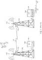
- FIG. 2is an illustration of intelligent backhaul radios (IBRs) deployed for cellular base station backhaul with obstructed LOS according to one embodiment of the invention.
- IBRsintelligent backhaul radios
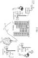
- FIG. 3is a block diagram of an IBR according to one embodiment of the invention.
- FIG. 4is a block diagram of an IBR antenna array according to one embodiment of the invention.
- FIG. 5is a block diagram illustrating the closed-loop feedback for beamforming optimization.
- FIG. 6is a block diagram illustrating steps in the beamforming optimization at the receiver.
- FIG. 2illustrates deployment of intelligent backhaul radios (IBRs) in accordance with an embodiment of the invention.
- the IBRs 200are deployable at street level with obstructions such as trees 204 , hills 208 , buildings 212 , etc. between them.
- the IBRs 200are also deployable in configurations that include point to multipoint (PMP), as shown in FIG. 2 , as well as point to point (PTP).
- PMPpoint to multipoint
- PTPpoint to point
- each IBR 200may communicate with more than one other IBR 200 .
- cellular network infrastructureis more commonly deployed using “microcells” or “picocells.”
- compact base stations (eNodeBs) 216are situated outdoors at street level. When such eNodeBs 216 are unable to connect locally to optical fiber or a copper wireline of sufficient data bandwidth, then a wireless connection to a fiber “point of presence” (POP) requires obstructed LOS capabilities, as described herein.
- POPpoint of presence
- the IBRs 200include an Aggregation End IBR (AE-IBR) and Remote End IBRs (RE-IBRs).
- the eNodeB 216 associated with the AE-IBRis typically connected locally to the core network via a fiber POP 220 .
- the RE-IBRs and their associated eNodeBs 216are typically not connected to the core network via a wireline connection; instead, the RE-IBRs are wirelessly connected to the core network via the AE-IBR.
- the wireless connections between the IBRsinclude obstructions (i.e., there may be an obstructed LOS connection between the RE-IBRs and the AE-IBR).
- FIG. 3illustrates an exemplary embodiment of the IBRs 200 shown in FIG. 2 .
- the IBRs 200include interfaces 304 , interface bridge 308 , MAC 312 , modem 324 , channel MUX 328 , RF 332 , which includes Tx1 . . . TxM 336 and Rx1 . . . RxN 340 , antenna array 348 (includes multiple antennas 352 ), a Radio Link Controller (RLC) 356 and a Radio Resource Controller (RRC) 360 .
- the IBRmay optionally include an Intelligent Backhaul Management System (IBMS) agent as shown in FIG. 7 of U.S. patent application Ser. No. 14/337,744.
- IBMSIntelligent Backhaul Management System
- the external interfaces of the IBRare a starting point for describing some fundamental differences between the numerous different embodiments of the IBR 200 and either conventional PTP radios or other commonly known radio systems, such as those built to existing standards including 802.11n (WiFi), 802.11ac (WiFi), 802.16e (WiMax) or 4G LTE.
- the IBR Interface Bridge 308physically interfaces to standards-based wired data networking interfaces 304 as Ethernet 1 through Ethernet P. “P” represents a number of separate Ethernet interfaces over twisted-pair, coax or optical fiber.
- the IBR Interface Bridge 308can multiplex and buffer the P Ethernet interfaces 304 with the IBR MAC 312 .
- the IBR Interface Bridge 308preserves “Quality of Service” (QoS) or “Class of Service” (CoS) prioritization as indicated, for example, in IEEE 802.1q 3-bit Priority Code Point (PCP) fields within the Ethernet frame headers, such that either the IBR MAC 312 schedules such frames for transmission according to policies configured within or communicated to the IBR 200 , or the IBR interface bridge 308 schedules the transfer of such frames to the IBR MAC 312 such that the same net effect occurs.
- QoSQuality of Service
- CoSClass of Service
- the IBR interface bridge 308also forwards and prioritizes the delivery of frames to or from another IBR over an instant radio link based on Multiprotocol Label Switching (MPLS) or Multiprotocol Label Switching Transport Profile (MPLS-TP).
- MPLSMultiprotocol Label Switching
- MPLS-TPMultiprotocol Label Switching Transport Profile
- U.S. patent application Ser. No. 14/337,744provides additional description of exemplary embodiments of the interfaces 304 and the interface bridge 308 of the IBR 200 .
- U.S. patent application Ser. No. 13/632,993provides additional description of exemplary embodiments of an IBMS that includes an IBMS Agent in communication with or IBMS components and the IBR Interface Bridge 308 as well as MAC 312 and/or RRC 360 .
- U.S. patent application Ser. No. 13/632,993also describes an IBR with an integrated Carrier Ethernet switch.
- FIG. 4illustrates an exemplary embodiment of an IBR Antenna Array 348 .
- FIG. 4illustrates an antenna array having Q directive gain antennas 352 (i.e., where the number of antennas is greater than 1).
- the IBR Antenna Array 348includes an IBR RF Switch Fabric 412 , RF interconnections 404 , a set of Front-ends 408 and the directive gain antennas 352 .
- the RF interconnections 404can be, for example, circuit board traces and/or coaxial cables.
- the RF interconnections 404connect the IBR RF Switch Fabric 412 and the set of Front-ends 408 .
- Each Front-end 408is associated with an individual directive gain antenna 352 , numbered consecutively from 1 to Q.
- U.S. patent application Ser. No. 14/337,744, U.S. patent application Ser. No. 14/336,958, and U.S. patent application Ser. No. 14/108,200provide additional description of the Front-end 408 and various embodiments thereof as applicable to different IBR duplexing schemes such as Time Division Duplexing (TDD), Frequency Division Duplexing (FDD) and Zero Division Duplexing (ZDD).
- TDDTime Division Duplexing
- FDDFrequency Division Duplexing
- ZDDZero Division Duplexing
- Front-end 408may include a transmit/receive switch, one or more RF low pass and/or bandpass filters, and either a low-noise amplifier (LNA) in the receive path or a power amplifier (PA) in the transmit path.
- Front-end 408may include a duplex filter, one or more additional RF low pass and/or bandpass filters, and either a low-noise amplifier (LNA) in the receive path or a power amplifier (PA) in the transmit path.
- Another common embodiment for FDDhas certain directive gain antenna elements 352 used only for transmit and then Front-end 408 for such transmit antenna elements would have a PA and one or more RF filters for a transmit FDD sub-band and has certain directive gain antenna elements 352 used only for receive and then Front-end 408 for such receive antenna elements would have an LNA and one or more RF filters for a receive FDD sub-band.
- certain directive gain antenna elements 352are used only for transmit and others only for receive with respective Front-ends as described for FDD except that the RF filters overlap in the frequency domain for both transmit and receive (i.e. no separate transmit and receive sub-bands).
- each antenna 352has a directivity gain Gq.
- each directive gain antenna 352may use only moderate directivity compared to antennas in conventional PTP systems at a comparable RF transmission frequency.
- typical values of Gqare on the order of 10 to 20 dBi for each antenna at RF transmission frequencies below 10 GHz.
- the total number of individual antenna elements 352 , Qis at least greater than or equal to the larger of the number of RF transmit chains 336 , M, and the number of RF receive chains 340 , N.
- some or all of the antennas 352may be split into pairs of polarization diverse antenna elements realized by either two separate feeds to a nominally single radiating element or by a pair of separate orthogonally oriented radiating elements.
- certain antenna elements 352may be configured with different antenna gain Gq and/or radiation patterns compared to others in the same IBR. Also, in many embodiments, such as for those employing FDD or ZDD, U.S. patent application Ser. No.
- the IBR RF Switch Fabric 412provides selectable RF connections between certain RF-Tx-m and/or certain RF-Rx-n to the various individual antenna elements 352 via various front-end 408 embodiments.
- the RF Switch Fabric 412is comprised of one or more RF switches where each RF switch has a selective set of one or mappings between the two or more RF ports on each switch.
- the individual antenna elements 352are coupled via a transmit-only front-end and/or the IBR RF Switch Fabric 412 to only a transmit chain output RF-Tx-m or coupled via a receive-only front-end and/or the IBR RF Switch Fabric 412 to only a receive chain output RF-Rx-n to advantageously enable separate optimization of the receive antenna array from that of the transmit antenna array.
- U.S. patent application Ser. No. 14/337,744, U.S. patent application Ser. No. 14/336,958, and U.S. patent application Ser. No. 14/108,200provide additional description of different embodiments of the IBR RF Switch Fabric 412 as applicable to TDD, FDD and ZDD in different product configurations.
- IBR embodimentsmay provide selectable RF connections between certain RF-Tx-m and/or certain RF-Rx-n to the various individual antenna elements 352 via various front-end 408 embodiments with structures different than the IBR RF Switch Fabric 412 , as also disclosed at least in U.S. patent application Ser. No. 14/337,744.
- certain IBR embodimentsmay utilize selective coupling structures between antenna elements and RF chains that comprise combiners or splitters where the phase and/or amplitude of a transmit or receive signal in certain paths of a combiner or splitter can be different from that of other paths.
- such selective coupling structuresmay include one or more upconverters or downconverters such that at least one splitter or combiner may include at least one path at an intermediate frequency (IF).
- IFintermediate frequency
- one or more switches in the implementation of the selectable RF connectionsmay also operate at IF.
- the actual instant selective coupling parameterssuch as a switch setting, or a path phase and/or an amplitude, or a splitting or combining path selection may be characterized by an appropriate set of selective coupling settings.
- the Radio Resource Control (RRC) 360may generate or cause to be generated such a set of selective coupling settings.
- the IBR RF 332also includes transmit RF and receive RF chains 336 , 340 .
- each element of transmit RF chain 336takes a transmit chain input signal such as digital baseband quadrature signals I Tm and Q Tm and then converts them to a transmit RF signal RF-Tx-m at an RF carrier frequency typically below 10 GHz.
- each element of receive RF chain 340converts a receive RF signal RF-Rx-n at an RF carrier frequency typically below 10 GHz to a receive chain output signal such as digital baseband quadrature signals IRn and QRn.
- each receive RF chaincomprises at least a vector demodulator and two analog to digital converters that are capable of producing such digital baseband quadrature signals IRn and QRn.
- each transmit RF chaincomprises at least a vector modulator and two digital to analog converters that are capable of operating from such digital baseband quadrature signals I Tm and Q Tm .
- the transmit RF and/or receive RF chainsmay operate at or operate with an intermediate frequency (or IF) that is also respectively upconverted or downconverted to the instant RF carrier frequency.
- Such upconverters or downconvertersmay be comprised within such transmit RF or receive RF chains. In some embodiments, such upconverters or downconverters may be comprised within the selectable RF connections as described above.
- IBR elementsinclude the IBR MAC 312 , the Radio Link Control (RLC) 356 , the Radio Resource Control (RRC) 360 and the optional IBMS Agent.
- RLCRadio Link Control
- RRCRadio Resource Control
- IBR embodimentsare possible wherein the MAC 312 , RLC 356 , RRC 360 and the optional IBMS Agent are distinct structural entities, more commonly IBRs are realized wherein the MAC 312 , RLC 356 , RRC 360 and the optional IBMS Agent as well as portions of the IBR Interface Bridge 308 are software modules executing on one or more microprocessors.
- SDRSoftware Defined Radio
- the one or more microprocessors used for elements of the PHY layerare physically separate from those used for the MAC 312 or other layers and are physically connected or connectable to certain hardware cores such as FFTs, Viterbi decoders, DFEs, etc.
- the RRC 360 and RLC 356may interact with the IBR MAC 312 and various elements of the IBR PHY at either the instant IBR or other IBRs in the instant link via “normal” frame transfers, direct local control signals via the conceptual IBR Control plane, or certain fields within a link control block that is transmitted periodically in certain superframes. Both the RRC 360 and the RLC 356 may execute concurrent control loops with the respective goals of optimizing radio resource allocations and optimizing radio link parameters for current resources in view of the dynamic propagation environment conditions (including uncoordinated interference if applicable), IBR loading, and possibly system-wide performance goals (via the optional IBMS Agent or other IBR to IBR control communications links).
- both the RRC 360 and the RLC 356are implemented as software modules executing on one or more processors.
- the primary responsibility of the RLC 356 in exemplary IBRsis to set or cause to be set the current transmit Modulation and Coding Scheme (MC S) and output power for each active link.
- the RLC 356causes the transmit power control (TPC) of the IBR to be maintained both in a relative sense amongst active links, particularly of interest for the AE-IBR in a PMP configuration, and also in an overall sense across all transmits chains and antennas.
- the RRCperforms some or all of the transmit power control (TPC) functionality.
- the RLC 356can determine its MCS and TPC selections across active links based on information from various sources within the IBR.
- the IBR MACcan deliver RLC control frames from other IBRs with information from such other IBRs (for example, RSSI, decoder metrics, FCS failure rates, etc.) that is useful in setting MCS and TPC at the transmitting IBR.
- RLC control frames from an associated IBRmay directly request or demand that the RLC in the instant IBR change its MCS and/or TPC values for transmit directly on either a relative or absolute basis.
- link control blockmay be used in place of or in addition to such control frames to carry such information.
- the primary responsibility of the RRC 360is to set or cause to be set at least the one or more active RF carrier frequencies (or alternatively, active RF channel center frequencies), the one or more active channel bandwidths, the choice of transmit and receive channel equalization and multiplexing strategies, the configuration and assignment of one or more modulated streams amongst one of more modulator cores, the number of active transmit and receive RF chains, and the selection of certain antenna elements and their mappings to the various RF chains (the set of selective coupling settings).
- the RRCmay also set or cause to be set the superframe timing, the cyclic prefix length, and/or the criteria by which blocks of Training Pilots are inserted.
- the RRC 360allocates portions of the IBR operational resources, including time multiplexing of currently selected resources, to the task of testing certain links between an AE-IBR and one or more RE-IBRs.
- the RRC 360evaluates such tests by monitoring at least the same link quality metrics as used by the RLC 656 . Additionally, in some embodiments, additional RRC-specific link testing metrics are also used.
- the RRC 360can also exchange control frames or control signaling using the link control block with a peer RRC at the other end of an instant link to, for example, provide certain link testing metrics or request or direct the peer RRC to obtain link specific testing metrics at the other end of the instant link for communication back to RRC 360 .
- the RRC 360causes changes to current resource assignments in response to tested alternatives based on policies that are configured in the IBR and/or set by the optional IBMS Agent.
- An exemplary policyincludes selecting resources based on link quality metrics predicted to allow the highest throughput MCS settings at lowest TPC value. Additional exemplary policies may factor in minimizing interference by the instant link to other AE-IBR to RE-IBR links (or other radio channel users such as conventional PTP radios) either detected at the instant IBRs or known to exist at certain physical locations nearby as set in configuration tables or communicated by the optional IBMS Agent or other IBR to IBR control communications links as described, for example, in co-pending U.S. patent application Ser. No. 14/098,456, the entirety of which is hereby incorporated by reference.
- U.S. patent application Ser. No. 14/098,456discloses exemplary systems and methods for control communications links in the form of inline or embedded signals that may be suitable for exchange of control information between IBRs that otherwise lack any IBR to IBR communication path. Such policies may also be weighted proportionately to reach a blended optimum choice amongst policy goals or ranked sequentially in importance.
- the selection of either the one or more active RF carrier frequencies used by the RF chains of the IBR RF, the one or more active channel bandwidths used by the IBR MAC, IBR Modem, IBR Channel MUX and IBR RF, the superframe timing, the cyclic prefix length, or the insertion policy for blocks of Training Pilotsis determined at the AE-IBR for any given link.
- the RE-IBR in such an arrangementcan request, for example, an RF carrier frequency or channel bandwidth change by the AE-IBR by sending an RRC control frame in response to current link conditions at the RE-IBR and its current RRC policies.
- an AE-IBRsends the affected RE-IBRs an RRC control frame specifying at least the parameters for the new RF frequency and/or channel bandwidth of the affected links as well as a proposed time, such as a certain superframe sequence index, at which the change-over will occur (or alternatively, denies the request).
- the AE-IBRthen makes the specified change after receiving confirmation RRC control frames from the affected RE-IBRs or sends a cancellation RRC control frame if such confirmations are not received before the scheduled change.
- RRCmay send such information on the link control block instead of or in addition to using control frames.
- An RE-IBRtypically attempts to utilize all available modulator and demodulator cores and streams as well as all available RF chains to maximize the robustness of its link to a particular AE-IBR.
- the primary local RRC decisionis then to set these various antenna selectivity options.
- the AE-IBR and RE-IBRoptimize their resource allocations independently such that there is little distinction between the RRC strategies at the AE-IBR versus the RE-IBR.
- U.S. patent application Ser. No. 14/337,744, U.S. patent application Ser. No. 14/336,958, and U.S. patent application Ser. No. 14/108,200provide additional description of different embodiments of the RRC 360 as applicable to TDD, FDD and ZDD in different product configurations.
- IBR Modem 324 and IBR Channel MUX 328depend somewhat on the specific modulation format(s) deployed by the IBR.
- the IBRrequires a modulation format suitable for a broadband channel subject to frequency-selective fading and multipath self-interference due to the desired PHY data rates and ranges in obstructed LOS propagation environments.
- Many known modulation formats for such broadband channelsare possible for the IBR.
- Two such modulation formats for the IBRare (1) Orthogonal Frequency Division Multiplexing (OFDM) and (2) Single-Carrier Frequency Domain Equalization (SC-FDE). Both modulation formats are well known, share common implementation elements, and have various advantages and disadvantages relative to each other.
- OFDMOrthogonal Frequency Division Multiplexing
- SC-FDESingle-Carrier Frequency Domain Equalization
- the IBRutilizes multiple antennas and transmit and/or receive chains, which can be utilized advantageously by several well-known baseband signal processing techniques that exploit multipath broadband channel propagation.
- Such techniquesinclude Multiple-Input, Multiple-Output (MIMO), MIMO Spatial Multiplexing (MIMO-SM), beamforming (BF), maximal ratio combining (MRC), and Space Division Multiple Access (SDMA).
- MIMOMultiple-Input, Multiple-Output
- MIMO-SMMIMO Spatial Multiplexing
- BFbeamforming
- MRCmaximal ratio combining
- SDMASpace Division Multiple Access
- the IBR Modem 324comprises one or modulator cores each of which comprises such functional elements as scramblers, encoders, interleavers, stream parsers, symbol groupers and symbol mappers.
- each modulator core within the IBR Modem 324typically transforms a data stream from the IBR MAC 312 into a symbol stream that can be passed to the IBR Channel MUX 328 .
- the IBR Modem 324also comprises one or demodulator cores each of which comprises such functional elements as descramblers, decoders, deinterleavers, stream multiplexers, and soft decision symbol demappers.
- each demodulator core within the IBR Modem 324typically transforms a stream of estimated receive symbols, such as represented by a Log-Likelihood Ratio (LLR), from the IBR Channel MUX 328 into a data stream that can be passed to the IBR MAC 312 .
- LLRLog-Likelihood Ratio
- U.S. patent application Ser. No. 14/337,744, U.S. patent application Ser. No. 14/336,958, and U.S. patent application Ser. No. 14/108,200provide additional description of different embodiments of the IBR Modem 324 as applicable to TDD, FDD and ZDD in different product configurations.
- the IBR Channel MUX 328comprises a transmit path channel multiplexer that may or may not be frequency selective and that in turn may comprise such functional elements as block assemblers, transmit channel equalizers, transmit multiplexers, cyclic prefix adders, block serializers, transmit digital front ends, preamble inserters, and pilot inserters.
- the transmit path of the IBR Channel MUX 328transforms one or more symbol streams from the IBR Modem 324 into inputs for the one or more transmit chains each comprised of baseband symbol samples.
- the IBR Channel MUX 328also comprises a frequency selective receive path channel multiplexer that in turn may comprise such functional elements as synchronizers, receive digital front ends, cyclic prefix removers, channel equalizer coefficients generators, receive channel equalizers, receive stream multiplexers and complex Discrete Fourier Transformers (DFT).
- a frequency selective receive path channel multiplexerthat in turn may comprise such functional elements as synchronizers, receive digital front ends, cyclic prefix removers, channel equalizer coefficients generators, receive channel equalizers, receive stream multiplexers and complex Discrete Fourier Transformers (DFT).
- DFTDiscrete Fourier Transformers
- Such exemplary frequency selective receive path channel multiplexersmay also comprise at least one of a Space Division Multiple Access (SDMA) combiner or equalizer, a maximal ratio combining (MRC) combiner or equalizer, a minimum mean squared error (MMSE) combiner or equalizer, an Eigen Beam Forming (EBF) combiner or equalizer, a receive beam forming (BF) combiner or equalizer, a Zero Forcing (ZF) combiner or equalizer, a channel estimator, a Maximal Likelihood (DL) detector, an Interference Canceller (IC), a VBLAST combiner or equalizer, a Discrete Fourier Transformer (DFT), a Fast Fourier Transformer (FFT), or an Inverse Fast Fourier Transformer (IFFT).
- SDMASpace Division Multiple Access
- MRCmaximal ratio combining
- MMSEminimum mean squared error
- EMFEigen Beam Forming
- BFreceive beam forming
- ZFZero Forcing
- DLMaximal Likelihood
- ICInterference Can
- the receive path of the IBR Channel MUX 328transforms the outputs of the one or more receive chains each comprised of baseband symbol samples into one or more streams of estimated receive symbols for input into the IBR Modem 324 .
- U.S. patent application Ser. No. 14/337,744, U.S. patent application Ser. No. 14/336,958, and U.S. patent application Ser. No. 14/108,200provide additional description of different embodiments of the IBR Channel MUX 328 as applicable to TDD, FDD and ZDD in different product configurations.
- the IBR MAC 312comprises such functional elements as a management entity, a Tx buffer and scheduler, a control entity, an Rx buffer, a frame check sum (FCS) generator, a header generator, a header analyzer and an FCS analyzer.
- FCSframe check sum
- U.S. patent application Ser. No. 14/337,744, U.S. patent application Ser. No. 14/336,958, and U.S. patent application Ser. No. 14/108,200provide additional description of different embodiments of the IBR MAC 312 as applicable to TDD, FDD and ZDD in different product configurations.
- the superframeis typically on the order of 200 to 2000 ⁇ s duration and composed of transmit blocks of typically 10 to 30 ⁇ s duration.
- each IBR superframecomprises multiple transmit blocks including at least one preamble block that may be used at least for synchronization and/or channel estimation (or for channel propagation characteristics assessment), at least one link control block that provides information such as the Modulation and Coding Scheme (or “MCS”) for the data blocks in the instant or subsequent superframe, and at least several data blocks that can comprise control, management and/or user information bits.
- MCSModulation and Coding Scheme
- IBRsmay advantageously optimize the superframe duration at either or both of startup or dynamically during operation to increase superframe duration at times of minimal interference when infrequent frequency agility in channel bandwidth and/or center frequency is required; thereby, minimizing the non-payload overhead associated with short duration superframes.
- IBRsmay advantageously optimize the superframe duration at either or both of startup or dynamically during operation to decrease superframe duration at times of significant interference that require continuous frequency agility in channel bandwidth and/or center frequency; thereby, minimizing the time required to make a channel bandwidth and channel center frequency change to correspond to minimally interfered frequency spectrum.
- IBRsmay change channel center frequency and channel bandwidth on a block by block basis by signaling such changes in an FDD or ZDD scheme with control flags appended to a transmit block to minimize processing latency in receiving such control flags and making the signaled change.
- IBRsmay use an immediate preamble block transmission to enable determination of updated channel estimation or may derive a temporary estimation for use until the next regularly scheduled preamble by interpolating, extrapolating and/or recalling from previously stored channel estimation.
- interference mitigation in the time domainis also enhanced by block level retransmission.
- Thisenables otherwise unmitigated interference that causes block errors at the receiver to be corrected at minimal latency to the affected data frame(s).
- an ACK or NACKis sent as a control flag with a block identifier to minimize latency in causing a transmitter to re-transmit a buffered block.
- control flags and identifiersare appended to transmit blocks after all bit processing operations to minimize the block processing latency associated with such function as encoding, interleaving, scrambling, encrypting, etc. and their inverse operations at the receiver.
- IBRsadvantageously use a multitude of diverse receive antennas.
- the number of receive RF chains, each of which can be coupled to at least one distinct receive antennaequals or exceeds the number of receive symbol streams and the number of distinct receive antennas that collectively provide diversity in the spatial domain exceeds the number of receive symbol streams.
- the spatial domain diversitymay be achieved by distinct receive antennas that are i) separated physically in space, by at least one half wavelength but preferably by multiple wavelengths, ii) separated in directional orientation, in either azimuth or elevation but preferably at least such that their respective azimuthal beam widths do not substantially overlap, or iii) separated in polarization such as vertical and horizontal or other known orthogonal polarizations.
- Many embodiments of the IBRuse a combination of at least two of the above spatial domain diversity alternatives and some embodiments of the IBR use a combination of spatial domain diversity based upon all three—physical separation, azimuthal orientation, and orthogonal polarization.
- multiple transmit antenna elementsmay be used to send the same transmit chain by adaptive beamforming.
- signals from multiple transmit antenna elementsmust be processed at the transmitter to combine constructively over the air.
- Signals radiating from different transmit antenna elementsexperience different paths to the receiver.
- theyIn order to combine the RF signals, they must be aligned in both phase and sample timing offset (STO).
- STOsample timing offset
- the IBRmay, at startup, apply open-loop beamforming in which an arbitrary phase is applied in order to increase the probability of the peer node discovery.
- open-loop beamformingin which an arbitrary phase is applied in order to increase the probability of the peer node discovery.
- the transmitter and receiverwill begin adaptive beamforming optimization through a closed-loop feedback mechanism.
- closed-loop beamformingthe optimal beamforming parameters are estimated at the receiver and fed back to the transmitter through the reverse link.
- the illustration of the closed-loop feedback relationshipis depicted in FIG. 5 .
- the transmitterperiodically sends a training sequence through the wireless channel.
- the receiverestimates the channel for each transmit and receive antenna element pair.
- the receiveruses the channel estimate to compute the optimal STO and phase estimates for the current channel conditions. Once the estimates are ready, the receiver sends the estimates through the reverse link.
- the transmitterapplies the STO correction and phase alignment according to the received feedback.
- the channelis estimated at the receiver through a sounding preamble, which is a training sequence periodically sent by the transmitter.
- the sounding preambleis transmitted from all transmit antenna elements in the middle of the superframe.
- the timing of the sounding preambleis predetermined and is known at both the transmitter and receiver.
- the sounding preamblewhich is a unique sequence for each transmit antenna element, is interleaved in frequency. For an embodiment with M transmit antenna elements, a tone is inserted every M subcarriers for each transmit antenna in the frequency domain. This allows each transmit antenna element to maintain orthogonality for the receiver to estimate the channel characteristic independently between each transmit and receive antenna elements across the operating bandwidth.
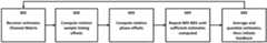
- FIG. 6shows a procedure 600 that is performed within a processor at the receiver to compute and feedback the phase and STO for optimal beamforming according to one embodiment of the invention.
- Procedure 600begins by a channel estimation using the received sounding preamble.
- the channel matrixis estimated at the receiver using the sounding preamble (block 601 ).
- the channel estimateis stored for each transmit and receive antenna pair and is used for the following steps for beamforming optimization.
- the receiverestimates the STO for each element in the channel (procedure 602 ).
- the STOcan be quantified by an absolute phase ramp across subcarriers in the frequency domain.
- the receiveruses the channel estimate to calculate the phase ramp across the subcarriers to find the STO for each transmit and receive antenna element pair. Specifically, the STO is estimated as
- the relative STO between the primary and alternate transmit antenna elementis computed to feed back to the transmitter. This represents the sample offsets between the two transmit antenna elements.
- the relative STOis computed between the primary transmit antenna element to and the alternate transmit antenna element ti.
- the receivercomputes the relative STO as
- the receiverthen computes the phase offsets across the transmit streams (block 603 ). In this stage, the receiver computes the phase offset between the primary and secondary transmit antenna elements, averaged over all receive antenna elements and frequency subcarriers. It is assumed that the phase does not vary over the operating bandwidth, and the estimate is averaged for all subcarriers. However, since the sounding preamble is placed in alternate subcarrier to maintain orthogonality, the computation must adjust for the subcarrier separation for the two transmit antennas. For example, if the sounding preamble offset was two subcarriers apart, the receiver computes the phase as
- the steps in block 601 through 603are repeated for multiple sounding preambles to obtain multiple samples of the beamforming estimates.
- the estimatesare continued until a predetermined number of estimates are obtained (block 604 ).
- the duration of the averaging periodmay vary depending on the state of the link. For example, a short averaging period may be ideal for an initial estimate after changing the center receive frequency.
- the estimatesare averaged and quantized after a sufficient number of estimates have been obtained (block 605 ).
- the relative STO estimatesare quantized into a half sample offset resolution in order to achieve a fine granularity.
- the phase estimatesare quantized around the unit circle, ranging from 0 to 360 degrees.
- the averaged estimatesare quantized into 8 bits each, and a feedback is initiated through the reverse link. Because the number of bits available for the feedback message is limited, the feedback is performed separately for the relative STO and phase estimate. In this invention, the relative STO and phase feedbacks are performed sequentially, in that order.
- the estimatesare applied starting at the next frame.
- the average channel estimate used for equalization filteringis reset to prevent transient effects due to variation in the channel after beamforming changes.
- the STOis applied by adding integer number of samples leaving the front end.
- the transmit filtersare adjusted to account for half sample offsets. Since the transmit filter is at twice the sampling frequency, adding a one tap delay is equivalent to removing half a sample from the transmitter. The two procedures are combined to apply the received STO feedback.
- phase feedbacksare applied by digitally multiplying samples leaving the front end by a unit magnitude phasor with the phase obtained according to the feedback.
- the phasoris multiplied to all samples except for the sounding preamble, which must be uniquely transmitted from each transmit antenna element.
- the same phasoris continuously applied at the transmitter until a new phase estimate feedback is obtained.
- the receivermay also dynamically determine whether or not to use the beamforming estimates. For example, the performance of the link is not sensitive to small changes in beamforming phase.
- the receivermay locally store the phase estimates from the previously feedback. To prevent unnecessary feedbacks, the receiver may discard the estimate if the absolute difference between the current and previously fed back phase estimate is less than a predetermined amount.
- the IBRmay use statistics of the estimates, such as the maximum, minimum, mean, or variance to determine whether a feedback is appropriate for a given averaging period. For instance, it may not be suitable to send a feedback if estimates within an averaging period are largely varying. If the absolute difference between the maximum and minimum estimate during the averaging period is greater than a predetermined threshold, the STO estimate may be discarded for that window.
- One or more of the methodologies or functions described hereinmay be embodied in a computer-readable medium on which is stored one or more sets of instructions (e.g., software).
- the softwaremay reside, completely or at least partially, within memory and/or within a processor during execution thereof.
- the softwaremay further be transmitted or received over a network.
- computer-readable mediumshould be taken to include a single medium or multiple media that store the one or more sets of instructions.
- computer-readable mediumshall also be taken to include any medium that is capable of storing, encoding or carrying a set of instructions for execution by a machine and that cause a machine to perform any one or more of the methodologies of the present invention.
- the term “computer-readable medium”shall accordingly be taken to include, but not be limited to, solid-state memories, and optical and magnetic media.
- Embodiments of the inventionhave been described through functional modules at times, which are defined by executable instructions recorded on computer readable media which cause a computer, microprocessors or chipsets to perform method steps when executed.
- the moduleshave been segregated by function for the sake of clarity. However, it should be understood that the modules need not correspond to discrete blocks of code and the described functions can be carried out by the execution of various code portions stored on various media and executed at various times.
Landscapes
- Engineering & Computer Science (AREA)
- Signal Processing (AREA)
- Computer Networks & Wireless Communication (AREA)
- Power Engineering (AREA)
- Quality & Reliability (AREA)
- Physics & Mathematics (AREA)
- Mathematical Physics (AREA)
- Discrete Mathematics (AREA)
- General Physics & Mathematics (AREA)
- Mobile Radio Communication Systems (AREA)
- Radio Transmission System (AREA)
Abstract
Description
Ĥrt[k]=Yrt[k]P*t[k],
where Yrt[k] is the received signal at receiver antenna rr from transmit antenna t for subcarrier k, and Pt[k] is the known sounding preamble. The channel estimate is stored for each transmit and receive antenna pair and is used for the following steps for beamforming optimization.
Claims (18)
Priority Applications (3)
| Application Number | Priority Date | Filing Date | Title |
|---|---|---|---|
| US15/825,032US10716111B2 (en) | 2011-08-17 | 2017-11-28 | Backhaul radio with adaptive beamforming and sample alignment |
| US16/901,976US11160078B2 (en) | 2011-08-17 | 2020-06-15 | Backhaul radio with adaptive beamforming and sample alignment |
| US17/501,556US20220070868A1 (en) | 2011-08-17 | 2021-10-14 | Backhaul radio with adaptive beamforming and sample alignment |
Applications Claiming Priority (14)
| Application Number | Priority Date | Filing Date | Title |
|---|---|---|---|
| US13/212,036US8238318B1 (en) | 2011-08-17 | 2011-08-17 | Intelligent backhaul radio |
| US13/371,366US8311023B1 (en) | 2011-08-17 | 2012-02-10 | Intelligent backhaul radio |
| US13/645,472US8811365B2 (en) | 2011-08-17 | 2012-10-04 | Intelligent backhaul radio |
| US201361910194P | 2013-11-29 | 2013-11-29 | |
| US14/337,744US9055463B2 (en) | 2011-08-17 | 2014-07-22 | Intelligent backhaul radio with receiver performance enhancement |
| US14/498,959US9049611B2 (en) | 2011-08-17 | 2014-09-26 | Backhaul radio with extreme interference protection |
| US14/688,550US9313674B2 (en) | 2011-08-17 | 2015-04-16 | Backhaul radio with extreme interference protection |
| US15/060,013US9474080B2 (en) | 2011-08-17 | 2016-03-03 | Full duplex backhaul radio with interference measurement during a blanking interval |
| US15/285,354US9655133B2 (en) | 2011-08-17 | 2016-10-04 | Radio with interference measurement during a blanking interval |
| US201662427055P | 2016-11-28 | 2016-11-28 | |
| US201662430229P | 2016-12-05 | 2016-12-05 | |
| US15/595,172US10051643B2 (en) | 2011-08-17 | 2017-05-15 | Radio with interference measurement during a blanking interval |
| US15/651,707US10548132B2 (en) | 2011-08-17 | 2017-07-17 | Radio with antenna array and multiple RF bands |
| US15/825,032US10716111B2 (en) | 2011-08-17 | 2017-11-28 | Backhaul radio with adaptive beamforming and sample alignment |
Related Parent Applications (2)
| Application Number | Title | Priority Date | Filing Date |
|---|---|---|---|
| US15/595,172Continuation-In-PartUS10051643B2 (en) | 2011-08-17 | 2017-05-15 | Radio with interference measurement during a blanking interval |
| US15/651,707Continuation-In-PartUS10548132B2 (en) | 2011-08-17 | 2017-07-17 | Radio with antenna array and multiple RF bands |
Related Child Applications (1)
| Application Number | Title | Priority Date | Filing Date |
|---|---|---|---|
| US16/901,976ContinuationUS11160078B2 (en) | 2011-08-17 | 2020-06-15 | Backhaul radio with adaptive beamforming and sample alignment |
Publications (2)
| Publication Number | Publication Date |
|---|---|
| US20180092099A1 US20180092099A1 (en) | 2018-03-29 |
| US10716111B2true US10716111B2 (en) | 2020-07-14 |
Family
ID=61686004
Family Applications (2)
| Application Number | Title | Priority Date | Filing Date |
|---|---|---|---|
| US15/825,032Expired - Fee RelatedUS10716111B2 (en) | 2011-08-17 | 2017-11-28 | Backhaul radio with adaptive beamforming and sample alignment |
| US16/901,976ActiveUS11160078B2 (en) | 2011-08-17 | 2020-06-15 | Backhaul radio with adaptive beamforming and sample alignment |
Family Applications After (1)
| Application Number | Title | Priority Date | Filing Date |
|---|---|---|---|
| US16/901,976ActiveUS11160078B2 (en) | 2011-08-17 | 2020-06-15 | Backhaul radio with adaptive beamforming and sample alignment |
Country Status (1)
| Country | Link |
|---|---|
| US (2) | US10716111B2 (en) |
Cited By (7)
| Publication number | Priority date | Publication date | Assignee | Title |
|---|---|---|---|---|
| US10932267B2 (en) | 2012-04-16 | 2021-02-23 | Skyline Partners Technology Llc | Hybrid band radio with multiple antenna arrays |
| US11160078B2 (en) | 2011-08-17 | 2021-10-26 | Skyline Partners Technology, Llc | Backhaul radio with adaptive beamforming and sample alignment |
| US11166280B2 (en) | 2011-08-17 | 2021-11-02 | Skyline Partners Technology, Llc | Backhaul radio with advanced error recovery |
| US11271613B2 (en) | 2011-08-17 | 2022-03-08 | Skyline Partners Technology Llc | Radio with spatially-offset directional antenna sub-arrays |
| US11283192B2 (en) | 2011-08-17 | 2022-03-22 | Skyline Partners Technology Llc | Aperture-fed, stacked-patch antenna assembly |
| US11303322B2 (en) | 2013-12-05 | 2022-04-12 | Skyline Partners Technology Llc | Advanced backhaul services |
| US11343684B2 (en) | 2011-08-17 | 2022-05-24 | Skyline Partners Technology Llc | Self organizing backhaul radio |
Families Citing this family (10)
| Publication number | Priority date | Publication date | Assignee | Title |
|---|---|---|---|---|
| US8761100B2 (en) | 2011-10-11 | 2014-06-24 | CBF Networks, Inc. | Intelligent backhaul system |
| US10548132B2 (en) | 2011-08-17 | 2020-01-28 | Skyline Partners Technology Llc | Radio with antenna array and multiple RF bands |
| US8502733B1 (en) | 2012-02-10 | 2013-08-06 | CBF Networks, Inc. | Transmit co-channel spectrum sharing |
| US10051643B2 (en) | 2011-08-17 | 2018-08-14 | Skyline Partners Technology Llc | Radio with interference measurement during a blanking interval |
| US10708918B2 (en) | 2011-08-17 | 2020-07-07 | Skyline Partners Technology Llc | Electronic alignment using signature emissions for backhaul radios |
| US11108442B1 (en)* | 2018-07-20 | 2021-08-31 | Qualcomm Incorporated | Calibration and implicit sounding using multi user multiple input multiple output transmissions |
| WO2020067940A1 (en)* | 2018-09-27 | 2020-04-02 | Telefonaktiebolaget Lm Ericsson (Publ) | Steering vector weighting for zf backhaul transmission |
| CN109167970A (en)* | 2018-10-11 | 2019-01-08 | 广州市九安智能技术股份有限公司 | A kind of anti-tampering Wireless video transmission method and system based on 2.4G wireless technology |
| US20220271907A1 (en)* | 2021-02-19 | 2022-08-25 | Meta Platforms, Inc. | Multiband fdd (frequency division duplex) radio configuration for reduction in transmit and receive path resources |
| US20230105730A1 (en)* | 2021-10-04 | 2023-04-06 | Skyworks Solutions, Inc. | Beamforming in radio frequency communication systems using frequency division duplexing |
Citations (199)
| Publication number | Priority date | Publication date | Assignee | Title |
|---|---|---|---|---|
| USD307274S (en) | 1988-04-27 | 1990-04-17 | Nec Corporation | Audio teleconference equipment with acoustic echo canceller |
| USD335128S (en) | 1990-02-09 | 1993-04-27 | Motorola, Inc. | Remote radio communications console |
| USD349897S (en) | 1992-07-08 | 1994-08-23 | Motorola, Inc. | Remote communications console |
| USD373771S (en) | 1993-07-22 | 1996-09-17 | Communications Technology Corporation | Pole mounted housing for telecommunication terminals |
| US5579367A (en) | 1995-03-13 | 1996-11-26 | Chaparral Communications, Inc. | Multi-medium closed-loop controlled satellite broadcast network for simple end-user operation |
| USD376367S (en) | 1995-05-09 | 1996-12-10 | Allen Telecom Group, Inc. | Antenna assembly with radome |
| USD376600S (en) | 1995-10-18 | 1996-12-17 | Datalogic Corporation | Telecommunications unit |
| US5604744A (en) | 1992-10-05 | 1997-02-18 | Telefonaktiebolaget Lm Ericsson | Digital control channels having logical channels for multiple access radiocommunication |
| US5809422A (en) | 1996-03-08 | 1998-09-15 | Watkins Johnson Company | Distributed microcellular communications system |
| USD401592S (en) | 1996-09-25 | 1998-11-24 | Japan Radio Co., Ltd. | Antenna radome |
| US5890055A (en) | 1995-07-28 | 1999-03-30 | Lucent Technologies Inc. | Method and system for connecting cells and microcells in a wireless communications network |
| USRE36591E (en) | 1994-02-16 | 2000-02-29 | Matsushita Electric Industrial Co., Ltd. | Transmission diversity for a CDMA/TDD mobile telecommunication system |
| US20010003443A1 (en) | 1996-10-10 | 2001-06-14 | Scott R. Velazquez | Communication system using geographic position data |
| US6253060B1 (en) | 1996-12-20 | 2001-06-26 | Airnet Communications Corporation | Method and apparatus employing wireless remote loopback capability for a wireless system repeater to provide end-to-end testing without a wireline connection |
| US20010030939A1 (en) | 1997-06-19 | 2001-10-18 | Qualcomm, Incorporated | Bit interleaving for orthogonal frequency division multiplexing in the transmission of digital signals |
| US20010033247A1 (en) | 1999-06-30 | 2001-10-25 | Andrew Singer | Remote tilt antenna system |
| US6310584B1 (en) | 2000-01-18 | 2001-10-30 | Xircom Wireless, Inc. | Low profile high polarization purity dual-polarized antennas |
| US20010038674A1 (en)* | 1997-07-31 | 2001-11-08 | Francois Trans | Means and method for a synchronous network communications system |
| US20010049295A1 (en) | 1999-12-27 | 2001-12-06 | Hidehiro Matsuoka | Radio communication apparatus using adaptive antenna |
| US20010050927A1 (en) | 1997-08-15 | 2001-12-13 | Bruce E. Johnson | Data storage communication channel and method of transmitting data |
| US20020008672A1 (en) | 1998-09-21 | 2002-01-24 | Tantivy Communications, Inc. | Adaptive antenna for use in wireless communication systems |
| USD455420S1 (en) | 1999-04-28 | 2002-04-09 | Detewe Ag & Co. | Telecommunications device |
| US6377217B1 (en) | 1999-09-14 | 2002-04-23 | Paratek Microwave, Inc. | Serially-fed phased array antennas with dielectric phase shifters |
| US20020060993A1 (en) | 1998-04-06 | 2002-05-23 | Dent Paul W. | Multi-signal transmit array with low intermodulation |
| US20020064141A1 (en) | 2000-11-24 | 2002-05-30 | Takashi Sakakura | Radio communication control station, radio communication terminal, home agent, and radio communication method |
| US20020077068A1 (en) | 1998-07-10 | 2002-06-20 | Dent Paul W. | Radio communication system with adaptive polarization |
| US20020111182A1 (en) | 2001-02-14 | 2002-08-15 | Telefonaktiebolaget L M Ericsson | Self-sacrificing cellular system |
| US20020136170A1 (en) | 2001-01-19 | 2002-09-26 | Raze Technologies, Inc. | Wireless access system using selectively adaptable beam forming in TDD frames and method of operation |
| US6462710B1 (en) | 2001-02-16 | 2002-10-08 | Ems Technologies, Inc. | Method and system for producing dual polarization states with controlled RF beamwidths |
| US6463303B1 (en) | 2000-01-11 | 2002-10-08 | Metawave Communications Corporation | Beam forming and switching architecture |
| US20020146029A1 (en)* | 2001-04-06 | 2002-10-10 | Samsung Electronics Co., Ltd. | Apparatus and method for allocating walsh codes to access terminals in an adaptive antenna array CDMA wireless network |
| US6486828B1 (en) | 2000-07-26 | 2002-11-26 | Western Multiplex | Adaptive array antenna nulling |
| US6529172B2 (en) | 2000-08-11 | 2003-03-04 | Andrew Corporation | Dual-polarized radiating element with high isolation between polarization channels |
| US20030064753A1 (en) | 2001-09-28 | 2003-04-03 | Kasapi Athanasios A. | System and related methods for beamforming in a multi-point communications environment |
| US20030073463A1 (en) | 1997-03-03 | 2003-04-17 | Joseph Shapira | Active antenna array configuration and control for cellular communication systems |
| US20030086366A1 (en) | 2001-03-06 | 2003-05-08 | Branlund Dale A. | Adaptive communications methods for multiple user packet radio wireless networks |
| US20030119501A1 (en) | 2001-12-04 | 2003-06-26 | Young-Hae Kim | Method and system for updating of home-zone list automatically in mobile telecommunication system |
| US20030123406A1 (en) | 2001-12-28 | 2003-07-03 | Nortel Networks Limited | Adaptive data rate control for mobile data transfer |
| US20030123384A1 (en) | 1997-02-24 | 2003-07-03 | Agee Brian G. | Stacked-carrier discrete multiple tone communication technology and combinations with code nulling, interference cancellation, retrodirective communication and adaptive antenna arrays |
| US20030153361A1 (en) | 2002-02-14 | 2003-08-14 | Ntt Docomo, Inc. | Antenna apparatus for base station and method of optimizing traffic capacity in CDMA communications system |
| US20030162566A1 (en) | 2000-05-05 | 2003-08-28 | Joseph Shapira | System and method for improving polarization matching on a cellular communication forward link |
| US20040006573A1 (en) | 2001-06-18 | 2004-01-08 | Nomura Takashi | Data transmission apparatus, data transmission method, and data transmission method program |
| US20040018843A1 (en) | 1999-02-22 | 2004-01-29 | Telefonaktiebolaget Lm Ericsson | Mobile radio system and a method for channel allocation in a mobile radio system |
| US6697642B1 (en) | 2000-07-19 | 2004-02-24 | Texas Instruments Incorporated | Wireless communications apparatus |
| US20040063406A1 (en) | 2002-09-30 | 2004-04-01 | Paul Petrus | Transmission link adaptation |
| US20040063450A1 (en) | 2002-09-30 | 2004-04-01 | Uhlik Christopher R. | Transmitting signals on a channel used for traffic and access in a communications system |
| US20040095907A1 (en) | 2000-06-13 | 2004-05-20 | Agee Brian G. | Method and apparatus for optimization of wireless multipoint electromagnetic communication networks |
| US20040132454A1 (en) | 2002-06-28 | 2004-07-08 | Trott Mitchell D. | Efficient broadcast channel structure and use for spatial diversity communications |
| US20040137924A1 (en) | 2003-01-10 | 2004-07-15 | Belair Networks, Inc. | Automatic antenna selection for mesh backhaul network nodes |
| US20040151238A1 (en) | 2000-01-18 | 2004-08-05 | Masenten Wesley K. | Method and apparatus for canceling a transmit signal spectrum in a receiver bandwidth |
| US20040157613A1 (en) | 2003-02-12 | 2004-08-12 | David Steer | Self-selection of radio frequency channels to reduce co-channel and adjacent channel interference in a wireless distributed network |
| US20040165650A1 (en) | 2003-02-18 | 2004-08-26 | Kddi Corporation | Transmitter and receiver |
| US20040198452A1 (en) | 2002-07-30 | 2004-10-07 | Roy Sebastien Joseph Armand | Array receiver with subarray selection |
| US20040259497A1 (en) | 2000-07-26 | 2004-12-23 | Dent Paul W. | Satellite communications system using multiple earth stations |
| US20040259565A1 (en) | 2003-06-20 | 2004-12-23 | Nortel Networks Limited | Method and device for selecting parameters for a cellular radio communication network based on occurrence frequencies |
| US20050026616A1 (en) | 2003-07-31 | 2005-02-03 | Siemens Mobile Communications S.P.A. | Common radio resource management method in a multi-RAT cellular telephone network |
| US20050068231A1 (en) | 1998-09-21 | 2005-03-31 | Ipr Licensing, Inc. | Method and apparatus for adapting antenna array using received perdetermined signal |
| US20050075078A1 (en) | 2001-10-12 | 2005-04-07 | Jarmo Makinen | Adaptive point-to-point microwave radio system |
| US6912195B2 (en) | 2001-12-28 | 2005-06-28 | Motorola, Inc. | Frequency-domain MIMO processing method and system |
| USD507263S1 (en) | 2003-11-05 | 2005-07-12 | Sony Corporation | Adapter |
| US20050164664A1 (en) | 2000-07-21 | 2005-07-28 | Difonzo Daniel F. | Dynamically reconfigurable wireless networks (DRWiN) and methods for operating such networks |
| US20050202828A1 (en) | 2004-03-12 | 2005-09-15 | Pecen Mark E. | System and method for determining availability of radio access technology associated with a wireless network |
| US20050219140A1 (en) | 2004-04-01 | 2005-10-06 | Stella Doradus Waterford Limited | Antenna construction |
| US6985123B2 (en) | 2001-10-11 | 2006-01-10 | Kathrein-Werke Kg | Dual-polarization antenna array |
| US6995712B2 (en) | 2001-12-19 | 2006-02-07 | Victor Boyanov | Antenna element |
| US20060056365A1 (en) | 2004-09-13 | 2006-03-16 | Suman Das | Wireless communications system employing a network active set formed from base stations operable as primary and secondary agents |
| US7027837B1 (en) | 2001-09-27 | 2006-04-11 | Arraycomm Llc. | Antenna array for point-to-point microwave radio system |
| US20060079290A1 (en) | 1999-09-13 | 2006-04-13 | Kabushiki Kaisha Toshiba | Radio communication system |
| US20060141929A1 (en) | 2004-12-28 | 2006-06-29 | Lockie Douglas G | Cellular communication system |
| US20060164271A1 (en) | 2003-03-12 | 2006-07-27 | Walter Hirt | Method and apparatus for converting optical signals to radio channels |
| US20060181456A1 (en) | 2003-04-01 | 2006-08-17 | Yanzhong Dai | Method and apparatus for beamforming based on broadband antenna |
| US20060209746A1 (en) | 2005-02-09 | 2006-09-21 | Ntt Docomo, Inc. | Controller and transmission and reception method for radio communications in a transceiver for radio communications |
| US7133672B2 (en) | 2002-01-08 | 2006-11-07 | Motorola, Inc. | Method and apparatus for registration of a mobile station in a packet data communication system |
| US20060253526A1 (en) | 2003-09-09 | 2006-11-09 | Welch John T | Wireless networking system and method |
| US20060273952A1 (en) | 2005-06-03 | 2006-12-07 | Krikorian Kapriel V | Technique for compensation of transmit leakage in radar receiver |
| US20070030116A1 (en) | 2005-08-03 | 2007-02-08 | Kamilo Feher | Multimode communication system |
| WO2007014685A1 (en) | 2005-08-02 | 2007-02-08 | Trafobau Schindler Gmbh | Method and device for increasing an electric motor efficiency |
| US20070097899A1 (en) | 2003-12-22 | 2007-05-03 | Peter Larsson | Method and system of radio communications of traffic with different characteristics |
| US7221722B2 (en) | 2003-02-27 | 2007-05-22 | Motorola, Inc. | Method and apparatus for reducing interference within a communication system |
| US20070140374A1 (en) | 1996-08-29 | 2007-06-21 | Raleigh Gregory G | Spatio-temporal processing for communication |
| US20070146225A1 (en) | 2005-12-28 | 2007-06-28 | Kathrein-Werke Kg | Dual polarized antenna |
| US20070155431A1 (en) | 2006-01-05 | 2007-07-05 | Alcatel Lucent | Method of semidynamic centralized interference coordination for cellular systems |
| US20070165552A1 (en) | 2001-12-28 | 2007-07-19 | Arraycomm Llc. | System and related methods for beamforming in a multi-point communications environment |
| US20070183439A1 (en) | 2006-01-05 | 2007-08-09 | Osann Robert Jr | Combined directional and mobile interleaved wireless mesh network |
| US20070189408A1 (en)* | 2006-02-10 | 2007-08-16 | Shai Waxman | Mobile station and method for channel sounding using a single radio frequency transmitter chain in a multiple-input multiple-output (MIMO) system |
| US7260141B2 (en) | 2001-02-28 | 2007-08-21 | Itt Manufacturing Enterprises, Inc. | Integrated beamformer/modem architecture |
| US20070195736A1 (en) | 2006-02-23 | 2007-08-23 | Masanori Taira | Wireless communication method, base station and, wireless communication system |
| US20070218910A1 (en) | 2006-03-15 | 2007-09-20 | Motorola, Inc. | Dynamic beam steering of backhaul traffic |
| US20070222697A1 (en) | 2004-10-15 | 2007-09-27 | Caimi Frank M | Methods and Apparatuses for Adaptively Controlling Antenna Parameters to Enhance Efficiency and Maintain Antenna Size Compactness |
| US7280082B2 (en) | 2003-10-10 | 2007-10-09 | Cisco Technology, Inc. | Antenna array with vane-supported elements |
| US20070243878A1 (en) | 2006-02-23 | 2007-10-18 | Masanori Taira | Wireless communication method |
| US7289478B1 (en) | 1999-07-30 | 2007-10-30 | At&T Corp. | Method and apparatus for a fixed wireless broadband access and wireless LAN integration |
| US7292663B1 (en) | 2001-09-26 | 2007-11-06 | L-3 Communications Corporation | Efficient space-time adaptive processing (STAP) filter for global positioning system (GPS) receivers |
| US20070264935A1 (en) | 2006-05-02 | 2007-11-15 | Nextivity, Inc. | FDD/TDD wireless link for UNII band |
| WO2008007375A2 (en) | 2006-07-13 | 2008-01-17 | Designart Networks Ltd | Wimax access point network with backhaul technology |
| US20080014948A1 (en) | 2006-07-14 | 2008-01-17 | Lgc Wireless, Inc. | System for and method of for providing dedicated capacity in a cellular network |
| US20080043882A1 (en) | 2006-08-21 | 2008-02-21 | Interdigital Technology Corporation | Wireless communication method and apparatus for performing hybrid timing and frequency offset for processing synchronization signals |
| USD565534S1 (en) | 2006-04-26 | 2008-04-01 | Independent Technologies Inc. | Transmitter antenna |
| US20080080364A1 (en) | 2006-07-13 | 2008-04-03 | Oz Barak | Point to point communication method |
| US20080090575A1 (en) | 2006-07-13 | 2008-04-17 | Oz Barak | WiMAX ACCESS POINT NETWORK WITH BACKHAUL TECHNOLOGY |
| US7394439B1 (en) | 2006-06-19 | 2008-07-01 | Sprintcommunications Company L.P. | Multi-link antenna array that conforms to cellular leasing agreements for only one attachment fee |
| US20080159212A1 (en) | 2006-12-29 | 2008-07-03 | Lucent Technologies Inc | Method and system of using a wireless link in the backhaul connection |
| US7403501B2 (en) | 2005-05-03 | 2008-07-22 | Cisco Technology, Inc. | System and method for implementing suppression in a communications environment |
| US20080181183A1 (en) | 2007-01-16 | 2008-07-31 | Simon Gale | Shared Radio Backhaul System |
| US20080181282A1 (en) | 2007-01-25 | 2008-07-31 | Adc Telecommunications, Inc. | Modular wireless communications platform |
| US20080242232A1 (en) | 2007-03-27 | 2008-10-02 | Adc Telecommunications, Inc. | Digitized reverse link monitor |
| US20080240307A1 (en) | 2007-03-30 | 2008-10-02 | Sony Deutschland Gmbh | Single carrier high rate wireless system |
| US20080274745A1 (en) | 2007-05-06 | 2008-11-06 | Designart Networks Ltd | Interference mitigation technique |
| US20090010238A1 (en) | 2007-07-05 | 2009-01-08 | Designart Networks Ltd | Method for channel estimation in a point-to-point communication network. |
| US20090029645A1 (en) | 2007-07-25 | 2009-01-29 | Teenay Wireless, Inc. | Multi-Tier Backhaul Network System with Traffic Differentiation and Advanced Processing Capabilities and Methods Therefor |
| US20090052411A1 (en) | 2007-08-21 | 2009-02-26 | Fimax Technology Limited | Adaptive interference control |
| US20090067526A1 (en) | 2001-05-08 | 2009-03-12 | Albert Ratermann | Method and device for transferring data in a multi-carrier system having parallel concatenated encoding and modulation |
| US20090111463A1 (en) | 2007-10-31 | 2009-04-30 | Motorola, Inc. | Incumbent spectrum hold device |
| US20090121963A1 (en) | 2007-11-14 | 2009-05-14 | Greene Matthew R | Tuning matching circuits for transmitter and receiver bands as a function of transmitter metrics |
| US20090143017A1 (en) | 2007-12-04 | 2009-06-04 | Designart Networks Ltd | Method and device for wireless communication using mimo techniques |
| USD595274S1 (en) | 2007-12-11 | 2009-06-30 | Smarteq Wireless Ab | Antenna |
| USD596627S1 (en) | 2007-05-28 | 2009-07-21 | Samsung Electronics Co., Ltd. | Subscriber in-house equipment for wireless broadband system |
| US7587177B1 (en) | 2005-12-12 | 2009-09-08 | Exalt, Inc. | Electronically configurable transmit and receive paths for FDD wireless communication devices |
| US20090231197A1 (en)* | 2008-03-13 | 2009-09-17 | Cubic Corporation | Digital beamforming antenna and datalink array |
| US7599290B2 (en) | 2006-08-11 | 2009-10-06 | Latitude Broadband, Inc. | Methods and systems for providing quality of service in packet-based core transport networks |
| US20090252250A1 (en) | 2008-04-02 | 2009-10-08 | Samsung Electronics Co. Ltd. | Apparatus and method for beamforming based on generalized eigen-analysis in multiple input multiple output wireless communication system |
| US20090252134A1 (en) | 2008-04-04 | 2009-10-08 | Ludger Schlicht | Methods and systems for a mobile, broadband, routable internet |
| US20090264087A1 (en) | 2008-04-17 | 2009-10-22 | Samsung Electronics Co., Ltd. | Apparatus and method for beamforming considering interference amount in broadband wireless communication system |
| US20090274130A1 (en) | 2006-09-27 | 2009-11-05 | Dragonwave, Inc. | Wireless network communication apparatus, methods, and integrated antenna structures |
| US20090286506A1 (en) | 2008-05-15 | 2009-11-19 | Level 3 Communications, Llc | Fixed Mobile Convergent Service in Enterprise Environments |
| USD604724S1 (en) | 2007-07-30 | 2009-11-24 | Aruba Networks, Inc. | Wireless local area network device |
| US20090304055A1 (en) | 2008-05-21 | 2009-12-10 | Robert Nino | Messenger strand mounted pico-cell radio |
| US20090312022A1 (en) | 2008-06-13 | 2009-12-17 | Fujitsu Microelectronics Limited | Self Organizing Network |
| US20090323621A1 (en) | 2008-06-30 | 2009-12-31 | Designart Networks Ltd | Wireless backhaul |
| US20100009694A1 (en) | 2008-07-10 | 2010-01-14 | Steve Fischer | Cell site power conservation |
| US20100033396A1 (en) | 2007-04-27 | 2010-02-11 | Nec Corporation | Sector antenna |
| US20100046462A1 (en) | 2005-03-22 | 2010-02-25 | Koki Uwano | Wireless communication system |
| US20100046439A1 (en) | 2008-08-21 | 2010-02-25 | Motorola, Inc. | Antenna-aware method for transmitting packets in a wireless communication network |
| US20100046421A1 (en) | 2007-12-31 | 2010-02-25 | David Adams | Multibeam Antenna System |
| US20100056205A1 (en) | 2006-06-14 | 2010-03-04 | Telefonaktiebolaget Lm Ericsson (Publ) | Base transceiver stations and method of operating thereof |
| US20100087158A1 (en) | 2008-10-08 | 2010-04-08 | Ali Corporation | Full frequency scanning method and channel parameter adjusting method for smart antenna |
| US20100104038A1 (en) | 2008-10-29 | 2010-04-29 | Cisco Technology, Inc. | Multidimensional channel estimation without sounding signals |
| US20100157970A1 (en) | 2008-12-18 | 2010-06-24 | Designart Networks Ltd | Multiple antenna wireless telecommunication method and system |
| US20100172422A1 (en) | 2006-03-29 | 2010-07-08 | Hidenori Maruyama | Transmitter-receiver and Operation Control Method of the Same |
| USD619571S1 (en) | 2009-09-11 | 2010-07-13 | Hon Hai Precision Industry Co., Ltd. | Modem |
| US20100202391A1 (en) | 2009-02-10 | 2010-08-12 | Qualcomm Incorporated | Access point resource negotiation and allocation over a wireless interface |
| USD622256S1 (en) | 2009-02-06 | 2010-08-24 | Oticon A/S | Wireless communication device |
| US20100261423A1 (en) | 2009-04-14 | 2010-10-14 | Peter Stanforth | System and method for managing spectrum allocation |
| US20100269143A1 (en) | 2009-04-21 | 2010-10-21 | Irving Rabowsky | System and Method for Satellite Enhanced Command, Control, and Surveillance Services Between Network Management Centers and Unmanned Land and Aerial Devices |
| US20100272006A1 (en) | 2009-01-06 | 2010-10-28 | Texas Instruments Incorporated | Design of In-Band Backhaul for Wireless Relays in Wireless Networks |
| US20100303015A1 (en) | 2009-06-01 | 2010-12-02 | Samsung Electronics Co., Ltd. | Apparatus and method for calibration for cooperative multiple input multiple output in a wireless communication system |
| US7848241B2 (en) | 2006-01-31 | 2010-12-07 | Motorola Mobility, Inc. | Method and apparatus for handoff control in mobile communications systems |
| US20100309048A1 (en) | 2009-06-05 | 2010-12-09 | Qualcomm Incorporated | Optimization for finding direction of arrival in smart antennas |
| US20110044279A1 (en) | 2008-04-30 | 2011-02-24 | Niklas Johansson | Self-Backhauling in LTE |
| WO2011030960A1 (en) | 2009-09-09 | 2011-03-17 | 엘지전자주식회사 | Method for sensing whitespace in a wireless lan system, and apparatus for performing same |
| US20110065448A1 (en) | 2008-05-09 | 2011-03-17 | Nortel Networks Limited | System and Method for Supporting Antenna Beamforming in a Cellular Network |
| US20110070855A1 (en) | 2008-05-23 | 2011-03-24 | Telefonaktiebolaget L M Ericsson (Publ) | System and method for mast vibration compensation |
| US20110085525A1 (en) | 2009-09-16 | 2011-04-14 | At&T Mobility Ii Llc | Leveraging a femtocell network for premises management or monitoring |
| US20110090885A1 (en) | 2009-10-15 | 2011-04-21 | Saeid Safavi | Methods and apparatus for centralized and coordinated interference mitigation in a wlan network |
| US20110103292A1 (en) | 2009-08-14 | 2011-05-05 | Pasad Kalpendu R | DL Backhaul Control Channel Design For Relays |
| US20110164186A1 (en) | 2010-01-05 | 2011-07-07 | Qualcomm Incorporated | Distinguishing and communicating between white space devices transmitting atsc-compatible signals |
| WO2011080299A2 (en) | 2010-01-04 | 2011-07-07 | Thrane & Thrane A/S | A terminal and a method for communicating simultaneously on two frequencies |
| US20110182174A1 (en) | 2010-01-28 | 2011-07-28 | Samsung Electronics Co. Ltd. | Techniques for millimeter wave mobile communication |
| USD643025S1 (en) | 2010-11-15 | 2011-08-09 | World Products, Llc | Antenna radome |
| US20110206155A1 (en) | 2008-10-30 | 2011-08-25 | Mitsubishi Electric Corporation | Communication apparatus and communication system |
| US20110235514A1 (en) | 2010-03-25 | 2011-09-29 | Qual Comm Incorporated | Data radio bearer mapping in a telecommunication network with relays |
| US8078109B1 (en) | 2007-04-13 | 2011-12-13 | Wireless Stategies, Inc. | Concurrently coordinated microwave paths in coordinated frequency bands |
| US20120058777A1 (en) | 2010-09-02 | 2012-03-08 | Public Wireless, Inc. | Systems and methods for controlling quality of service at picocells using agnostic platform |
| US20120063472A1 (en) | 2009-03-12 | 2012-03-15 | Michel Le Pallec | Method for processing distributed data having a chosen type for synchronizing communication nodes of a data packet network, and associated device |
| US20120108284A1 (en) | 2007-03-09 | 2012-05-03 | Bhaskar Patel | Method and apparatus for multiple radio receive chains in wireless communication systems |
| US8175535B2 (en) | 2008-02-27 | 2012-05-08 | Telefonaktiebolaget Lm Ericsson (Publ) | Active cancellation of transmitter leakage in a wireless transceiver |
| US20120122477A1 (en) | 2010-11-15 | 2012-05-17 | Qualcomm Incorporated | Geo-location aided sensing |
| US20120135724A1 (en) | 2008-08-07 | 2012-05-31 | Trex Enterprises Corp | Circuit switched millimeter wave communication network |
| US8238318B1 (en) | 2011-08-17 | 2012-08-07 | CBF Networks, Inc. | Intelligent backhaul radio |
| US8249527B2 (en) | 2006-02-09 | 2012-08-21 | Vixs Systems, Inc. | Multimedia client/server system, client module, multimedia server, radio receiver and methods for use therewith |
| US20120213086A1 (en) | 2010-12-02 | 2012-08-23 | Buffalo Inc. | Wireless lan device and controlling method thereof |
| US20120224574A1 (en) | 2011-01-10 | 2012-09-06 | Telefonaktiebolaget L M Ericsson (Publ) | Handling of Acknowledgement Messages in a Relay Network Node |
| US8300590B1 (en) | 2011-10-11 | 2012-10-30 | CBF Networks, Inc. | Intelligent backhaul system |
| US20130044028A1 (en) | 2011-08-17 | 2013-02-21 | CBF Networks, Inc. | Intelligent backhaul radio and antenna system |
| US8385305B1 (en) | 2012-04-16 | 2013-02-26 | CBF Networks, Inc | Hybrid band intelligent backhaul radio |
| US8422540B1 (en) | 2012-06-21 | 2013-04-16 | CBF Networks, Inc. | Intelligent backhaul radio with zero division duplexing |
| US20130137444A1 (en) | 2004-06-10 | 2013-05-30 | Interdigital Technology Corporation | Method and system of using smart antennas for backhauling |
| US8462709B2 (en) | 2004-10-20 | 2013-06-11 | Qualcomm Incorporated | Multiple frequency band operation in wireless networks |
| US8487813B2 (en) | 2009-06-01 | 2013-07-16 | Siklu Communication ltd. | Antenna alignment method and apparatus |
| US8502733B1 (en) | 2012-02-10 | 2013-08-06 | CBF Networks, Inc. | Transmit co-channel spectrum sharing |
| US20130288593A1 (en) | 2009-06-09 | 2013-10-31 | The Directv Group, Inc. | Rotation pointed antenna for fixed wireless wide area networks |
| US8649418B1 (en) | 2013-02-08 | 2014-02-11 | CBF Networks, Inc. | Enhancement of the channel propagation matrix order and rank for a wireless channel |
| US20140050126A1 (en) | 2006-10-26 | 2014-02-20 | Apple Inc. | Frame Structure for a Multi-Hop Wireless System |
| USD704174S1 (en) | 2012-08-14 | 2014-05-06 | CBF Networks, Inc. | Intelligent backhaul radio with symmetric wing radome |
| US20140184457A1 (en) | 2011-08-17 | 2014-07-03 | CBF Networks, Inc. | Backhaul radio with a substrate tab-fed antenna assembly |
| US20150016561A1 (en) | 2011-08-17 | 2015-01-15 | CBF Networks, Inc. | Advanced backhaul services |
| US20150049720A1 (en) | 2011-08-17 | 2015-02-19 | CBF Networks, Inc. | Backhaul radio with extreme interference protection |
| EP2843863A1 (en) | 2013-07-23 | 2015-03-04 | CBF Networks, Inc. | Intelligent backhaul radio with improved radar detection capability |
| US8982772B2 (en) | 2011-08-17 | 2015-03-17 | CBF Networks, Inc. | Radio transceiver with improved radar detection |
| US8989762B1 (en) | 2013-12-05 | 2015-03-24 | CBF Networks, Inc. | Advanced backhaul services |
| US20150230105A1 (en) | 2011-08-17 | 2015-08-13 | CBF Networks, Inc. | Self organizing backhaul radio |
| US20160004522A1 (en) | 2011-09-29 | 2016-01-07 | Michael Connelly | Multiple Virtual Machines in a Mobile Virtualization Platform |
| US20160192374A1 (en) | 2011-08-17 | 2016-06-30 | CBF Networks, Inc. | Full duplex backhaul radio with interference measurement during a blanking interval |
| US20160285611A1 (en) | 2011-08-17 | 2016-09-29 | CBF Networks, Inc. | Radio with oobe victim detection |
| US20170251484A1 (en) | 2011-08-17 | 2017-08-31 | CBF Networks, Inc. | Radio with interference measurement during a blanking interval |
| US20170311307A1 (en) | 2011-08-17 | 2017-10-26 | Skyline Partners Technology Llc | Electronic alignment using signature emissions for backhaul radios |
| US20170318589A1 (en) | 2011-08-17 | 2017-11-02 | Skyline Partners Technology Llc | Radio with antenna array and multiple rf bands |
| US20180084553A1 (en) | 2011-08-17 | 2018-03-22 | Skyline Partners Technology Llc | Backhaul radio with advanced error recovery |
| US20190045492A1 (en) | 2016-03-30 | 2019-02-07 | Kyocera Corporation | Base station and radio terminal |
Family Cites Families (14)
| Publication number | Priority date | Publication date | Assignee | Title |
|---|---|---|---|---|
| US5973613A (en) | 1990-06-15 | 1999-10-26 | Raytheon Company | Personal messaging system and method |
| US7076168B1 (en) | 1998-02-12 | 2006-07-11 | Aquity, Llc | Method and apparatus for using multicarrier interferometry to enhance optical fiber communications |
| US6539209B1 (en) | 2000-05-30 | 2003-03-25 | Lucent Technologies Inc. | Code-division, multiple-access base station having transmit diversity |
| US6359596B1 (en) | 2000-07-28 | 2002-03-19 | Lockheed Martin Corporation | Integrated circuit mm-wave antenna structure |
| JP4671478B2 (en) | 2000-08-08 | 2011-04-20 | 富士通株式会社 | Wavelength multiplexing optical communication system and wavelength multiplexing optical communication method |
| GB0020088D0 (en) | 2000-08-15 | 2000-10-04 | Fujitsu Ltd | Adaptive beam forming |
| JP4052835B2 (en) | 2001-12-28 | 2008-02-27 | 株式会社日立製作所 | Wireless transmission system for multipoint relay and wireless device used therefor |
| WO2007126931A2 (en) | 2006-03-31 | 2007-11-08 | Ev3 Inc. | Embolic protection devices having radiopaque markers |
| US8175532B2 (en) | 2006-06-06 | 2012-05-08 | Qualcomm Incorporated | Apparatus and method for wireless communication via at least one of directional and omni-direction antennas |
| WO2010121254A1 (en) | 2009-04-17 | 2010-10-21 | Raytheon Company | Distributed maximal ratio combining receiver architecture |
| AU2010307335B2 (en)* | 2009-10-16 | 2014-11-27 | Dynatest International A/S | Determination of subgrade modulus and stiffness of pavement layers for measurement bearing capacity under fast moving wheel load |
| US9887728B2 (en) | 2011-02-03 | 2018-02-06 | The Board Of Trustees Of The Leland Stanford Junior University | Single channel full duplex wireless communications |
| US20120262576A1 (en) | 2011-04-14 | 2012-10-18 | Andrew Blough Sechrist | Method And System For A Network Of Multiple Live Video Sources |
| US10716111B2 (en) | 2011-08-17 | 2020-07-14 | Skyline Partners Technology Llc | Backhaul radio with adaptive beamforming and sample alignment |
- 2017
- 2017-11-28USUS15/825,032patent/US10716111B2/ennot_activeExpired - Fee Related
- 2020
- 2020-06-15USUS16/901,976patent/US11160078B2/enactiveActive
Patent Citations (293)
| Publication number | Priority date | Publication date | Assignee | Title |
|---|---|---|---|---|
| USD307274S (en) | 1988-04-27 | 1990-04-17 | Nec Corporation | Audio teleconference equipment with acoustic echo canceller |
| USD335128S (en) | 1990-02-09 | 1993-04-27 | Motorola, Inc. | Remote radio communications console |
| USD349897S (en) | 1992-07-08 | 1994-08-23 | Motorola, Inc. | Remote communications console |
| US5604744A (en) | 1992-10-05 | 1997-02-18 | Telefonaktiebolaget Lm Ericsson | Digital control channels having logical channels for multiple access radiocommunication |
| USD373771S (en) | 1993-07-22 | 1996-09-17 | Communications Technology Corporation | Pole mounted housing for telecommunication terminals |
| USRE36591E (en) | 1994-02-16 | 2000-02-29 | Matsushita Electric Industrial Co., Ltd. | Transmission diversity for a CDMA/TDD mobile telecommunication system |
| US5579367A (en) | 1995-03-13 | 1996-11-26 | Chaparral Communications, Inc. | Multi-medium closed-loop controlled satellite broadcast network for simple end-user operation |
| USD376367S (en) | 1995-05-09 | 1996-12-10 | Allen Telecom Group, Inc. | Antenna assembly with radome |
| US5890055A (en) | 1995-07-28 | 1999-03-30 | Lucent Technologies Inc. | Method and system for connecting cells and microcells in a wireless communications network |
| USD376600S (en) | 1995-10-18 | 1996-12-17 | Datalogic Corporation | Telecommunications unit |
| US5809422A (en) | 1996-03-08 | 1998-09-15 | Watkins Johnson Company | Distributed microcellular communications system |
| US20070140374A1 (en) | 1996-08-29 | 2007-06-21 | Raleigh Gregory G | Spatio-temporal processing for communication |
| USD401592S (en) | 1996-09-25 | 1998-11-24 | Japan Radio Co., Ltd. | Antenna radome |
| US20010003443A1 (en) | 1996-10-10 | 2001-06-14 | Scott R. Velazquez | Communication system using geographic position data |
| US6253060B1 (en) | 1996-12-20 | 2001-06-26 | Airnet Communications Corporation | Method and apparatus employing wireless remote loopback capability for a wireless system repeater to provide end-to-end testing without a wireline connection |
| US20030123384A1 (en) | 1997-02-24 | 2003-07-03 | Agee Brian G. | Stacked-carrier discrete multiple tone communication technology and combinations with code nulling, interference cancellation, retrodirective communication and adaptive antenna arrays |
| US20030073463A1 (en) | 1997-03-03 | 2003-04-17 | Joseph Shapira | Active antenna array configuration and control for cellular communication systems |
| US20010030939A1 (en) | 1997-06-19 | 2001-10-18 | Qualcomm, Incorporated | Bit interleaving for orthogonal frequency division multiplexing in the transmission of digital signals |
| US20010038674A1 (en)* | 1997-07-31 | 2001-11-08 | Francois Trans | Means and method for a synchronous network communications system |
| US20010050927A1 (en) | 1997-08-15 | 2001-12-13 | Bruce E. Johnson | Data storage communication channel and method of transmitting data |
| US20020060993A1 (en) | 1998-04-06 | 2002-05-23 | Dent Paul W. | Multi-signal transmit array with low intermodulation |
| US20020077068A1 (en) | 1998-07-10 | 2002-06-20 | Dent Paul W. | Radio communication system with adaptive polarization |
| US20020008672A1 (en) | 1998-09-21 | 2002-01-24 | Tantivy Communications, Inc. | Adaptive antenna for use in wireless communication systems |
| US20050068231A1 (en) | 1998-09-21 | 2005-03-31 | Ipr Licensing, Inc. | Method and apparatus for adapting antenna array using received perdetermined signal |
| US20040018843A1 (en) | 1999-02-22 | 2004-01-29 | Telefonaktiebolaget Lm Ericsson | Mobile radio system and a method for channel allocation in a mobile radio system |
| USD455420S1 (en) | 1999-04-28 | 2002-04-09 | Detewe Ag & Co. | Telecommunications device |
| US20010033247A1 (en) | 1999-06-30 | 2001-10-25 | Andrew Singer | Remote tilt antenna system |
| US7289478B1 (en) | 1999-07-30 | 2007-10-30 | At&T Corp. | Method and apparatus for a fixed wireless broadband access and wireless LAN integration |
| US20060079290A1 (en) | 1999-09-13 | 2006-04-13 | Kabushiki Kaisha Toshiba | Radio communication system |
| US6377217B1 (en) | 1999-09-14 | 2002-04-23 | Paratek Microwave, Inc. | Serially-fed phased array antennas with dielectric phase shifters |
| US20010049295A1 (en) | 1999-12-27 | 2001-12-06 | Hidehiro Matsuoka | Radio communication apparatus using adaptive antenna |
| US6463303B1 (en) | 2000-01-11 | 2002-10-08 | Metawave Communications Corporation | Beam forming and switching architecture |
| US20010035844A1 (en) | 2000-01-18 | 2001-11-01 | Reece John K. | Low profile high polarization purity dual-polarized antennas |
| US20040151238A1 (en) | 2000-01-18 | 2004-08-05 | Masenten Wesley K. | Method and apparatus for canceling a transmit signal spectrum in a receiver bandwidth |
| US6310584B1 (en) | 2000-01-18 | 2001-10-30 | Xircom Wireless, Inc. | Low profile high polarization purity dual-polarized antennas |
| US20030162566A1 (en) | 2000-05-05 | 2003-08-28 | Joseph Shapira | System and method for improving polarization matching on a cellular communication forward link |
| US20040095907A1 (en) | 2000-06-13 | 2004-05-20 | Agee Brian G. | Method and apparatus for optimization of wireless multipoint electromagnetic communication networks |
| US6697642B1 (en) | 2000-07-19 | 2004-02-24 | Texas Instruments Incorporated | Wireless communications apparatus |
| US20050164664A1 (en) | 2000-07-21 | 2005-07-28 | Difonzo Daniel F. | Dynamically reconfigurable wireless networks (DRWiN) and methods for operating such networks |
| US6486828B1 (en) | 2000-07-26 | 2002-11-26 | Western Multiplex | Adaptive array antenna nulling |
| US20040259497A1 (en) | 2000-07-26 | 2004-12-23 | Dent Paul W. | Satellite communications system using multiple earth stations |
| US6529172B2 (en) | 2000-08-11 | 2003-03-04 | Andrew Corporation | Dual-polarized radiating element with high isolation between polarization channels |
| US20020064141A1 (en) | 2000-11-24 | 2002-05-30 | Takashi Sakakura | Radio communication control station, radio communication terminal, home agent, and radio communication method |
| US20020136170A1 (en) | 2001-01-19 | 2002-09-26 | Raze Technologies, Inc. | Wireless access system using selectively adaptable beam forming in TDD frames and method of operation |
| US20020111182A1 (en) | 2001-02-14 | 2002-08-15 | Telefonaktiebolaget L M Ericsson | Self-sacrificing cellular system |
| US6462710B1 (en) | 2001-02-16 | 2002-10-08 | Ems Technologies, Inc. | Method and system for producing dual polarization states with controlled RF beamwidths |
| US7260141B2 (en) | 2001-02-28 | 2007-08-21 | Itt Manufacturing Enterprises, Inc. | Integrated beamformer/modem architecture |
| US20030086366A1 (en) | 2001-03-06 | 2003-05-08 | Branlund Dale A. | Adaptive communications methods for multiple user packet radio wireless networks |
| US20020146029A1 (en)* | 2001-04-06 | 2002-10-10 | Samsung Electronics Co., Ltd. | Apparatus and method for allocating walsh codes to access terminals in an adaptive antenna array CDMA wireless network |
| US20090067526A1 (en) | 2001-05-08 | 2009-03-12 | Albert Ratermann | Method and device for transferring data in a multi-carrier system having parallel concatenated encoding and modulation |
| US20040006573A1 (en) | 2001-06-18 | 2004-01-08 | Nomura Takashi | Data transmission apparatus, data transmission method, and data transmission method program |
| US7292663B1 (en) | 2001-09-26 | 2007-11-06 | L-3 Communications Corporation | Efficient space-time adaptive processing (STAP) filter for global positioning system (GPS) receivers |
| US7027837B1 (en) | 2001-09-27 | 2006-04-11 | Arraycomm Llc. | Antenna array for point-to-point microwave radio system |
| US20030064753A1 (en) | 2001-09-28 | 2003-04-03 | Kasapi Athanasios A. | System and related methods for beamforming in a multi-point communications environment |
| US6985123B2 (en) | 2001-10-11 | 2006-01-10 | Kathrein-Werke Kg | Dual-polarization antenna array |
| US20050075078A1 (en) | 2001-10-12 | 2005-04-07 | Jarmo Makinen | Adaptive point-to-point microwave radio system |
| US20030119501A1 (en) | 2001-12-04 | 2003-06-26 | Young-Hae Kim | Method and system for updating of home-zone list automatically in mobile telecommunication system |
| US6995712B2 (en) | 2001-12-19 | 2006-02-07 | Victor Boyanov | Antenna element |
| US20070165552A1 (en) | 2001-12-28 | 2007-07-19 | Arraycomm Llc. | System and related methods for beamforming in a multi-point communications environment |
| US6912195B2 (en) | 2001-12-28 | 2005-06-28 | Motorola, Inc. | Frequency-domain MIMO processing method and system |
| US20030123406A1 (en) | 2001-12-28 | 2003-07-03 | Nortel Networks Limited | Adaptive data rate control for mobile data transfer |
| US7133672B2 (en) | 2002-01-08 | 2006-11-07 | Motorola, Inc. | Method and apparatus for registration of a mobile station in a packet data communication system |
| US20030153361A1 (en) | 2002-02-14 | 2003-08-14 | Ntt Docomo, Inc. | Antenna apparatus for base station and method of optimizing traffic capacity in CDMA communications system |
| US20040132454A1 (en) | 2002-06-28 | 2004-07-08 | Trott Mitchell D. | Efficient broadcast channel structure and use for spatial diversity communications |
| US20040198452A1 (en) | 2002-07-30 | 2004-10-07 | Roy Sebastien Joseph Armand | Array receiver with subarray selection |
| US20040063406A1 (en) | 2002-09-30 | 2004-04-01 | Paul Petrus | Transmission link adaptation |
| US20040063450A1 (en) | 2002-09-30 | 2004-04-01 | Uhlik Christopher R. | Transmitting signals on a channel used for traffic and access in a communications system |
| US7171223B2 (en) | 2003-01-10 | 2007-01-30 | Belair Networks, Inc. | Automatic antenna selection for mesh backhaul network nodes |
| US20040137924A1 (en) | 2003-01-10 | 2004-07-15 | Belair Networks, Inc. | Automatic antenna selection for mesh backhaul network nodes |
| US20040157613A1 (en) | 2003-02-12 | 2004-08-12 | David Steer | Self-selection of radio frequency channels to reduce co-channel and adjacent channel interference in a wireless distributed network |
| US20040165650A1 (en) | 2003-02-18 | 2004-08-26 | Kddi Corporation | Transmitter and receiver |
| US7221722B2 (en) | 2003-02-27 | 2007-05-22 | Motorola, Inc. | Method and apparatus for reducing interference within a communication system |
| US20060164271A1 (en) | 2003-03-12 | 2006-07-27 | Walter Hirt | Method and apparatus for converting optical signals to radio channels |
| US20060181456A1 (en) | 2003-04-01 | 2006-08-17 | Yanzhong Dai | Method and apparatus for beamforming based on broadband antenna |
| US20040259565A1 (en) | 2003-06-20 | 2004-12-23 | Nortel Networks Limited | Method and device for selecting parameters for a cellular radio communication network based on occurrence frequencies |
| US20050026616A1 (en) | 2003-07-31 | 2005-02-03 | Siemens Mobile Communications S.P.A. | Common radio resource management method in a multi-RAT cellular telephone network |
| US20060253526A1 (en) | 2003-09-09 | 2006-11-09 | Welch John T | Wireless networking system and method |
| US7280082B2 (en) | 2003-10-10 | 2007-10-09 | Cisco Technology, Inc. | Antenna array with vane-supported elements |
| USD507263S1 (en) | 2003-11-05 | 2005-07-12 | Sony Corporation | Adapter |
| US20070097899A1 (en) | 2003-12-22 | 2007-05-03 | Peter Larsson | Method and system of radio communications of traffic with different characteristics |
| US20050202828A1 (en) | 2004-03-12 | 2005-09-15 | Pecen Mark E. | System and method for determining availability of radio access technology associated with a wireless network |
| US20050219140A1 (en) | 2004-04-01 | 2005-10-06 | Stella Doradus Waterford Limited | Antenna construction |
| US20130137444A1 (en) | 2004-06-10 | 2013-05-30 | Interdigital Technology Corporation | Method and system of using smart antennas for backhauling |
| US20060056365A1 (en) | 2004-09-13 | 2006-03-16 | Suman Das | Wireless communications system employing a network active set formed from base stations operable as primary and secondary agents |
| US20070222697A1 (en) | 2004-10-15 | 2007-09-27 | Caimi Frank M | Methods and Apparatuses for Adaptively Controlling Antenna Parameters to Enhance Efficiency and Maintain Antenna Size Compactness |
| US8462709B2 (en) | 2004-10-20 | 2013-06-11 | Qualcomm Incorporated | Multiple frequency band operation in wireless networks |
| US20060141929A1 (en) | 2004-12-28 | 2006-06-29 | Lockie Douglas G | Cellular communication system |
| US20060209746A1 (en) | 2005-02-09 | 2006-09-21 | Ntt Docomo, Inc. | Controller and transmission and reception method for radio communications in a transceiver for radio communications |
| US7616554B2 (en) | 2005-02-09 | 2009-11-10 | Ntt Docomo, Inc. | Controller and transmission and reception method for radio communications in a transceiver for radio communications |
| US20100046462A1 (en) | 2005-03-22 | 2010-02-25 | Koki Uwano | Wireless communication system |
| US7403501B2 (en) | 2005-05-03 | 2008-07-22 | Cisco Technology, Inc. | System and method for implementing suppression in a communications environment |
| US20060273952A1 (en) | 2005-06-03 | 2006-12-07 | Krikorian Kapriel V | Technique for compensation of transmit leakage in radar receiver |
| WO2007014685A1 (en) | 2005-08-02 | 2007-02-08 | Trafobau Schindler Gmbh | Method and device for increasing an electric motor efficiency |
| US20070030116A1 (en) | 2005-08-03 | 2007-02-08 | Kamilo Feher | Multimode communication system |
| US7587177B1 (en) | 2005-12-12 | 2009-09-08 | Exalt, Inc. | Electronically configurable transmit and receive paths for FDD wireless communication devices |
| US20070146225A1 (en) | 2005-12-28 | 2007-06-28 | Kathrein-Werke Kg | Dual polarized antenna |
| US20070183439A1 (en) | 2006-01-05 | 2007-08-09 | Osann Robert Jr | Combined directional and mobile interleaved wireless mesh network |
| US20070155431A1 (en) | 2006-01-05 | 2007-07-05 | Alcatel Lucent | Method of semidynamic centralized interference coordination for cellular systems |
| US7848241B2 (en) | 2006-01-31 | 2010-12-07 | Motorola Mobility, Inc. | Method and apparatus for handoff control in mobile communications systems |
| US8249527B2 (en) | 2006-02-09 | 2012-08-21 | Vixs Systems, Inc. | Multimedia client/server system, client module, multimedia server, radio receiver and methods for use therewith |
| US20070189408A1 (en)* | 2006-02-10 | 2007-08-16 | Shai Waxman | Mobile station and method for channel sounding using a single radio frequency transmitter chain in a multiple-input multiple-output (MIMO) system |
| US20070243878A1 (en) | 2006-02-23 | 2007-10-18 | Masanori Taira | Wireless communication method |
| US20070195736A1 (en) | 2006-02-23 | 2007-08-23 | Masanori Taira | Wireless communication method, base station and, wireless communication system |
| US20070218910A1 (en) | 2006-03-15 | 2007-09-20 | Motorola, Inc. | Dynamic beam steering of backhaul traffic |
| US20100172422A1 (en) | 2006-03-29 | 2010-07-08 | Hidenori Maruyama | Transmitter-receiver and Operation Control Method of the Same |
| USD565534S1 (en) | 2006-04-26 | 2008-04-01 | Independent Technologies Inc. | Transmitter antenna |
| US20070264935A1 (en) | 2006-05-02 | 2007-11-15 | Nextivity, Inc. | FDD/TDD wireless link for UNII band |
| US20100056205A1 (en) | 2006-06-14 | 2010-03-04 | Telefonaktiebolaget Lm Ericsson (Publ) | Base transceiver stations and method of operating thereof |
| US7394439B1 (en) | 2006-06-19 | 2008-07-01 | Sprintcommunications Company L.P. | Multi-link antenna array that conforms to cellular leasing agreements for only one attachment fee |
| US20100128630A1 (en) | 2006-07-13 | 2010-05-27 | Designart Networks Ltd | Access point planning mechanism |
| US20080080364A1 (en) | 2006-07-13 | 2008-04-03 | Oz Barak | Point to point communication method |
| US7620370B2 (en) | 2006-07-13 | 2009-11-17 | Designart Networks Ltd | Mobile broadband wireless access point network with wireless backhaul |
| WO2008007375A2 (en) | 2006-07-13 | 2008-01-17 | Designart Networks Ltd | Wimax access point network with backhaul technology |
| US7593729B2 (en) | 2006-07-13 | 2009-09-22 | Designart Networks Ltd | Point to point link and communication method |
| US20080090575A1 (en) | 2006-07-13 | 2008-04-17 | Oz Barak | WiMAX ACCESS POINT NETWORK WITH BACKHAUL TECHNOLOGY |
| US20080014948A1 (en) | 2006-07-14 | 2008-01-17 | Lgc Wireless, Inc. | System for and method of for providing dedicated capacity in a cellular network |
| US7599290B2 (en) | 2006-08-11 | 2009-10-06 | Latitude Broadband, Inc. | Methods and systems for providing quality of service in packet-based core transport networks |
| US20080043882A1 (en) | 2006-08-21 | 2008-02-21 | Interdigital Technology Corporation | Wireless communication method and apparatus for performing hybrid timing and frequency offset for processing synchronization signals |
| US20090274130A1 (en) | 2006-09-27 | 2009-11-05 | Dragonwave, Inc. | Wireless network communication apparatus, methods, and integrated antenna structures |
| US20140050126A1 (en) | 2006-10-26 | 2014-02-20 | Apple Inc. | Frame Structure for a Multi-Hop Wireless System |
| US20080159212A1 (en) | 2006-12-29 | 2008-07-03 | Lucent Technologies Inc | Method and system of using a wireless link in the backhaul connection |
| US7948942B2 (en) | 2006-12-29 | 2011-05-24 | Alcatel-Lucent Usa Inc. | Method and system of using a wireless link in the backhaul connection |
| US20080181183A1 (en) | 2007-01-16 | 2008-07-31 | Simon Gale | Shared Radio Backhaul System |
| US20080181282A1 (en) | 2007-01-25 | 2008-07-31 | Adc Telecommunications, Inc. | Modular wireless communications platform |
| US20120108284A1 (en) | 2007-03-09 | 2012-05-03 | Bhaskar Patel | Method and apparatus for multiple radio receive chains in wireless communication systems |
| US20080242232A1 (en) | 2007-03-27 | 2008-10-02 | Adc Telecommunications, Inc. | Digitized reverse link monitor |
| US20080240307A1 (en) | 2007-03-30 | 2008-10-02 | Sony Deutschland Gmbh | Single carrier high rate wireless system |
| US8078109B1 (en) | 2007-04-13 | 2011-12-13 | Wireless Stategies, Inc. | Concurrently coordinated microwave paths in coordinated frequency bands |
| US7978144B2 (en) | 2007-04-27 | 2011-07-12 | Nec Corporation | Sector antenna |
| US20100033396A1 (en) | 2007-04-27 | 2010-02-11 | Nec Corporation | Sector antenna |
| US7756519B2 (en) | 2007-05-06 | 2010-07-13 | Designart Networks Ltd | Interference mitigation technique |
| US20080274745A1 (en) | 2007-05-06 | 2008-11-06 | Designart Networks Ltd | Interference mitigation technique |
| USD596627S1 (en) | 2007-05-28 | 2009-07-21 | Samsung Electronics Co., Ltd. | Subscriber in-house equipment for wireless broadband system |
| US20090010238A1 (en) | 2007-07-05 | 2009-01-08 | Designart Networks Ltd | Method for channel estimation in a point-to-point communication network. |
| US20090029645A1 (en) | 2007-07-25 | 2009-01-29 | Teenay Wireless, Inc. | Multi-Tier Backhaul Network System with Traffic Differentiation and Advanced Processing Capabilities and Methods Therefor |
| USD604724S1 (en) | 2007-07-30 | 2009-11-24 | Aruba Networks, Inc. | Wireless local area network device |
| US20090052411A1 (en) | 2007-08-21 | 2009-02-26 | Fimax Technology Limited | Adaptive interference control |
| US20090111463A1 (en) | 2007-10-31 | 2009-04-30 | Motorola, Inc. | Incumbent spectrum hold device |
| US20110250852A1 (en) | 2007-11-14 | 2011-10-13 | Paratek Microwave, Inc. | Tuning Matching Circuits for Transmitter and Receiver Bands as a Function of Transmitter Metrics |
| US20090121963A1 (en) | 2007-11-14 | 2009-05-14 | Greene Matthew R | Tuning matching circuits for transmitter and receiver bands as a function of transmitter metrics |
| US20130095765A1 (en) | 2007-11-14 | 2013-04-18 | Research In Motion Rf, Inc. | Tuning matching circuits for transmitter and receiver bands as a function of the transmitter metrics |
| US20090143017A1 (en) | 2007-12-04 | 2009-06-04 | Designart Networks Ltd | Method and device for wireless communication using mimo techniques |
| USD595274S1 (en) | 2007-12-11 | 2009-06-30 | Smarteq Wireless Ab | Antenna |
| US20100046421A1 (en) | 2007-12-31 | 2010-02-25 | David Adams | Multibeam Antenna System |
| US8175535B2 (en) | 2008-02-27 | 2012-05-08 | Telefonaktiebolaget Lm Ericsson (Publ) | Active cancellation of transmitter leakage in a wireless transceiver |
| US20090231197A1 (en)* | 2008-03-13 | 2009-09-17 | Cubic Corporation | Digital beamforming antenna and datalink array |
| US20090252250A1 (en) | 2008-04-02 | 2009-10-08 | Samsung Electronics Co. Ltd. | Apparatus and method for beamforming based on generalized eigen-analysis in multiple input multiple output wireless communication system |
| US20090252134A1 (en) | 2008-04-04 | 2009-10-08 | Ludger Schlicht | Methods and systems for a mobile, broadband, routable internet |
| US20090264087A1 (en) | 2008-04-17 | 2009-10-22 | Samsung Electronics Co., Ltd. | Apparatus and method for beamforming considering interference amount in broadband wireless communication system |
| US20110044279A1 (en) | 2008-04-30 | 2011-02-24 | Niklas Johansson | Self-Backhauling in LTE |
| US20110065448A1 (en) | 2008-05-09 | 2011-03-17 | Nortel Networks Limited | System and Method for Supporting Antenna Beamforming in a Cellular Network |
| US20090286506A1 (en) | 2008-05-15 | 2009-11-19 | Level 3 Communications, Llc | Fixed Mobile Convergent Service in Enterprise Environments |
| US20090304055A1 (en) | 2008-05-21 | 2009-12-10 | Robert Nino | Messenger strand mounted pico-cell radio |
| US20110070855A1 (en) | 2008-05-23 | 2011-03-24 | Telefonaktiebolaget L M Ericsson (Publ) | System and method for mast vibration compensation |
| US20090312022A1 (en) | 2008-06-13 | 2009-12-17 | Fujitsu Microelectronics Limited | Self Organizing Network |
| US20090323621A1 (en) | 2008-06-30 | 2009-12-31 | Designart Networks Ltd | Wireless backhaul |
| US20100009694A1 (en) | 2008-07-10 | 2010-01-14 | Steve Fischer | Cell site power conservation |
| US20120135724A1 (en) | 2008-08-07 | 2012-05-31 | Trex Enterprises Corp | Circuit switched millimeter wave communication network |
| US20100046439A1 (en) | 2008-08-21 | 2010-02-25 | Motorola, Inc. | Antenna-aware method for transmitting packets in a wireless communication network |
| US20100087158A1 (en) | 2008-10-08 | 2010-04-08 | Ali Corporation | Full frequency scanning method and channel parameter adjusting method for smart antenna |
| US20100104038A1 (en) | 2008-10-29 | 2010-04-29 | Cisco Technology, Inc. | Multidimensional channel estimation without sounding signals |
| US20110206155A1 (en) | 2008-10-30 | 2011-08-25 | Mitsubishi Electric Corporation | Communication apparatus and communication system |
| US20100157970A1 (en) | 2008-12-18 | 2010-06-24 | Designart Networks Ltd | Multiple antenna wireless telecommunication method and system |
| US20100272006A1 (en) | 2009-01-06 | 2010-10-28 | Texas Instruments Incorporated | Design of In-Band Backhaul for Wireless Relays in Wireless Networks |
| USD622256S1 (en) | 2009-02-06 | 2010-08-24 | Oticon A/S | Wireless communication device |
| US20100202391A1 (en) | 2009-02-10 | 2010-08-12 | Qualcomm Incorporated | Access point resource negotiation and allocation over a wireless interface |
| US20120063472A1 (en) | 2009-03-12 | 2012-03-15 | Michel Le Pallec | Method for processing distributed data having a chosen type for synchronizing communication nodes of a data packet network, and associated device |
| US20100261423A1 (en) | 2009-04-14 | 2010-10-14 | Peter Stanforth | System and method for managing spectrum allocation |
| US20100269143A1 (en) | 2009-04-21 | 2010-10-21 | Irving Rabowsky | System and Method for Satellite Enhanced Command, Control, and Surveillance Services Between Network Management Centers and Unmanned Land and Aerial Devices |
| US8487813B2 (en) | 2009-06-01 | 2013-07-16 | Siklu Communication ltd. | Antenna alignment method and apparatus |
| US20100303015A1 (en) | 2009-06-01 | 2010-12-02 | Samsung Electronics Co., Ltd. | Apparatus and method for calibration for cooperative multiple input multiple output in a wireless communication system |
| US20100309048A1 (en) | 2009-06-05 | 2010-12-09 | Qualcomm Incorporated | Optimization for finding direction of arrival in smart antennas |
| US20130288593A1 (en) | 2009-06-09 | 2013-10-31 | The Directv Group, Inc. | Rotation pointed antenna for fixed wireless wide area networks |
| US20110103292A1 (en) | 2009-08-14 | 2011-05-05 | Pasad Kalpendu R | DL Backhaul Control Channel Design For Relays |
| WO2011030960A1 (en) | 2009-09-09 | 2011-03-17 | 엘지전자주식회사 | Method for sensing whitespace in a wireless lan system, and apparatus for performing same |
| US20120184222A1 (en) | 2009-09-09 | 2012-07-19 | Yong Ho Seok | Method for Sensing Whitespace in a Wireless LAN System, and Apparatus for Performing Same |
| USD619571S1 (en) | 2009-09-11 | 2010-07-13 | Hon Hai Precision Industry Co., Ltd. | Modem |
| US20110085525A1 (en) | 2009-09-16 | 2011-04-14 | At&T Mobility Ii Llc | Leveraging a femtocell network for premises management or monitoring |
| US20110090885A1 (en) | 2009-10-15 | 2011-04-21 | Saeid Safavi | Methods and apparatus for centralized and coordinated interference mitigation in a wlan network |
| WO2011080299A2 (en) | 2010-01-04 | 2011-07-07 | Thrane & Thrane A/S | A terminal and a method for communicating simultaneously on two frequencies |
| WO2011080299A3 (en) | 2010-01-04 | 2011-08-25 | Thrane & Thrane A/S | A terminal and a method for communicating simultaneously on two frequencies |
| US20110164186A1 (en) | 2010-01-05 | 2011-07-07 | Qualcomm Incorporated | Distinguishing and communicating between white space devices transmitting atsc-compatible signals |
| US20110182174A1 (en) | 2010-01-28 | 2011-07-28 | Samsung Electronics Co. Ltd. | Techniques for millimeter wave mobile communication |
| US20110235514A1 (en) | 2010-03-25 | 2011-09-29 | Qual Comm Incorporated | Data radio bearer mapping in a telecommunication network with relays |
| US20120058777A1 (en) | 2010-09-02 | 2012-03-08 | Public Wireless, Inc. | Systems and methods for controlling quality of service at picocells using agnostic platform |
| US20120122477A1 (en) | 2010-11-15 | 2012-05-17 | Qualcomm Incorporated | Geo-location aided sensing |
| USD643025S1 (en) | 2010-11-15 | 2011-08-09 | World Products, Llc | Antenna radome |
| US20120213086A1 (en) | 2010-12-02 | 2012-08-23 | Buffalo Inc. | Wireless lan device and controlling method thereof |
| US20120224574A1 (en) | 2011-01-10 | 2012-09-06 | Telefonaktiebolaget L M Ericsson (Publ) | Handling of Acknowledgement Messages in a Relay Network Node |
| US20160278093A1 (en) | 2011-08-17 | 2016-09-22 | CBF Networks, Inc. | Hybrid band radio with adaptive antenna arrays |
| US20150223250A1 (en) | 2011-08-17 | 2015-08-06 | CBF Networks, Inc. | Intelligent backhaul radio |
| US20190159045A1 (en) | 2011-08-17 | 2019-05-23 | Skyline Partners Technology Llc | Self organizing backhaul radio |
| US20190044581A1 (en) | 2011-08-17 | 2019-02-07 | Skyline Partners Technology Llc | Radio with spatially-offset directional antenna sub-arrays |
| US20190007950A1 (en) | 2011-08-17 | 2019-01-03 | Skyline Partners Technology Llc | Radio with interference measurement during a blanking interval |
| US10051643B2 (en) | 2011-08-17 | 2018-08-14 | Skyline Partners Technology Llc | Radio with interference measurement during a blanking interval |
| US20180084553A1 (en) | 2011-08-17 | 2018-03-22 | Skyline Partners Technology Llc | Backhaul radio with advanced error recovery |
| US20130100897A1 (en) | 2011-08-17 | 2013-04-25 | CBF Networks, Inc. | Intelligent Backhaul Radio |
| US20170318482A1 (en) | 2011-08-17 | 2017-11-02 | Skyline Partners Technology Llc | Self organizing backhaul radio |
| WO2013025413A1 (en) | 2011-08-17 | 2013-02-21 | CBF Networks, Inc. | Intelligent backhaul radio |
| US8467363B2 (en) | 2011-08-17 | 2013-06-18 | CBF Networks, Inc. | Intelligent backhaul radio and antenna system |
| US20130044028A1 (en) | 2011-08-17 | 2013-02-21 | CBF Networks, Inc. | Intelligent backhaul radio and antenna system |
| US20170317725A1 (en) | 2011-08-17 | 2017-11-02 | Skyline Partners Technology Llc | Radio with spatially-offset directional antenna sub-arrays |
| US20170318589A1 (en) | 2011-08-17 | 2017-11-02 | Skyline Partners Technology Llc | Radio with antenna array and multiple rf bands |
| US20170311307A1 (en) | 2011-08-17 | 2017-10-26 | Skyline Partners Technology Llc | Electronic alignment using signature emissions for backhaul radios |
| US20130273974A1 (en) | 2011-08-17 | 2013-10-17 | CBF Networks, Inc. | Intelligent backhaul radio and antenna system |
| US20170251484A1 (en) | 2011-08-17 | 2017-08-31 | CBF Networks, Inc. | Radio with interference measurement during a blanking interval |
| US8311023B1 (en) | 2011-08-17 | 2012-11-13 | CBF Networks, Inc. | Intelligent backhaul radio |
| US9713155B2 (en) | 2011-08-17 | 2017-07-18 | CBF Networks, Inc. | Radio with antenna array and multiple RF bands |
| US9713019B2 (en) | 2011-08-17 | 2017-07-18 | CBF Networks, Inc. | Self organizing backhaul radio |
| US9713157B2 (en) | 2011-08-17 | 2017-07-18 | CBF Networks, Inc. | Method for installing a backhaul link with alignment signals |
| US9712216B2 (en) | 2011-08-17 | 2017-07-18 | CBF Networks, Inc. | Radio with spatially-offset directional antenna sub-arrays |
| US20170201025A1 (en) | 2011-08-17 | 2017-07-13 | CBF Networks, Inc. | Aperture-fed, stacked-patch antenna assembly |
| US9655133B2 (en) | 2011-08-17 | 2017-05-16 | CBF Networks, Inc. | Radio with interference measurement during a blanking interval |
| US20170127399A1 (en) | 2011-08-17 | 2017-05-04 | CBF Networks, Inc. | Method for installing a backhaul link with alignment signals |
| EP2745539A1 (en) | 2011-08-17 | 2014-06-25 | CBF Networks, Inc. | Intelligent backhaul radio |
| US20140184457A1 (en) | 2011-08-17 | 2014-07-03 | CBF Networks, Inc. | Backhaul radio with a substrate tab-fed antenna assembly |
| US20140184455A1 (en) | 2011-08-17 | 2014-07-03 | CBF Networks, Inc. | Backhaul radio with an aperture-fed antenna assembly |
| US8811365B2 (en) | 2011-08-17 | 2014-08-19 | CBF Networks, Inc. | Intelligent backhaul radio |
| US20170127421A1 (en) | 2011-08-17 | 2017-05-04 | CBF Networks, Inc. | Radio with antenna array and multiple rf bands |
| US8824442B2 (en) | 2011-08-17 | 2014-09-02 | CBF Networks, Inc. | Intelligent backhaul radio with adaptive channel bandwidth control |
| US20170126291A1 (en) | 2011-08-17 | 2017-05-04 | CBF Networks, Inc. | Radio with spatially-offset directional antenna sub-arrays |
| US8872715B2 (en) | 2011-08-17 | 2014-10-28 | CBF Networks, Inc. | Backhaul radio with a substrate tab-fed antenna assembly |
| US20140329562A1 (en) | 2011-08-17 | 2014-11-06 | CBF Networks, Inc. | Intelligent Backhaul Radio With Adaptive Channel Bandwidth Control |
| US8928542B2 (en) | 2011-08-17 | 2015-01-06 | CBF Networks, Inc. | Backhaul radio with an aperture-fed antenna assembly |
| US20150016561A1 (en) | 2011-08-17 | 2015-01-15 | CBF Networks, Inc. | Advanced backhaul services |
| US20150016362A1 (en) | 2011-08-17 | 2015-01-15 | CBF Networks, Inc. | Intelligent Backhaul Radio with receiver performance enhancement |
| US20170118760A1 (en) | 2011-08-17 | 2017-04-27 | CBF Networks, Inc. | Hybrid band radio with multiple antenna arrays |
| US9609530B2 (en) | 2011-08-17 | 2017-03-28 | CBF Networks, Inc. | Aperture-fed, stacked-patch antenna assembly |
| US20150049720A1 (en) | 2011-08-17 | 2015-02-19 | CBF Networks, Inc. | Backhaul radio with extreme interference protection |
| US9577700B2 (en) | 2011-08-17 | 2017-02-21 | CBF Networks, Inc. | Radio with asymmetrical directional antenna sub-arrays |
| US9577733B2 (en) | 2011-08-17 | 2017-02-21 | CBF Networks, Inc. | Method for installing a backhaul link with multiple antenna patterns |
| US8982772B2 (en) | 2011-08-17 | 2015-03-17 | CBF Networks, Inc. | Radio transceiver with improved radar detection |
| US9572163B2 (en) | 2011-08-17 | 2017-02-14 | CBF Networks, Inc. | Hybrid band radio with adaptive antenna arrays |
| US20150084826A1 (en) | 2011-08-17 | 2015-03-26 | David Andrew G. LEA | Aperture-fed, stacked-patch antenna assembly |
| US9001809B2 (en) | 2011-08-17 | 2015-04-07 | CBF Networks, Inc. | Intelligent backhaul radio with transmit and receive antenna arrays |
| US9049611B2 (en) | 2011-08-17 | 2015-06-02 | CBF Networks, Inc. | Backhaul radio with extreme interference protection |
| US20170026978A1 (en) | 2011-08-17 | 2017-01-26 | CBF Networks, Inc. | Radio with interference measurement during a blanking interval |
| US9055463B2 (en) | 2011-08-17 | 2015-06-09 | CBF Networks, Inc. | Intelligent backhaul radio with receiver performance enhancement |
| US20150194999A1 (en) | 2011-08-17 | 2015-07-09 | CBF Networks, Inc. | Backhaul radio with horizontally or vertically arranged receive antenna arrays |
| US20160316477A1 (en) | 2011-08-17 | 2016-10-27 | CBF Networks, Inc. | Backhaul radio with antenna array and multiple rf carrier frequencies |
| US20150223082A1 (en) | 2011-08-17 | 2015-08-06 | CBF Networks, Inc. | Backhaul radio with extreme interference protection |
| US20160285532A1 (en) | 2011-08-17 | 2016-09-29 | CBF Networks, Inc. | Method for installing a backhaul link with multiple antenna patterns |
| US20150230105A1 (en) | 2011-08-17 | 2015-08-13 | CBF Networks, Inc. | Self organizing backhaul radio |
| US20160285611A1 (en) | 2011-08-17 | 2016-09-29 | CBF Networks, Inc. | Radio with oobe victim detection |
| US9178558B2 (en) | 2011-08-17 | 2015-11-03 | CBF Networks, Inc. | Backhaul radio with horizontally or vertically arranged receive antenna arrays |
| US8238318B1 (en) | 2011-08-17 | 2012-08-07 | CBF Networks, Inc. | Intelligent backhaul radio |
| US20160248467A1 (en) | 2011-08-17 | 2016-08-25 | CBF Networks, Inc. | Radio with asymmetrical directional antenna sub-arrays |
| US20160192374A1 (en) | 2011-08-17 | 2016-06-30 | CBF Networks, Inc. | Full duplex backhaul radio with interference measurement during a blanking interval |
| US9350411B2 (en) | 2011-08-17 | 2016-05-24 | CBF Networks, Inc. | Full duplex backhaul radio with MIMO antenna array |
| US20160013831A1 (en) | 2011-08-17 | 2016-01-14 | CBF Networks, Inc. | Full duplex backhaul radio with mimo antenna array |
| US9282560B2 (en) | 2011-08-17 | 2016-03-08 | CBF Networks, Inc. | Full duplex backhaul radio with transmit beamforming and SC-FDE modulation |
| US20160135192A1 (en) | 2011-08-17 | 2016-05-12 | CBF Networks, Inc. | Full duplex backhaul radio with transmit beamforming |
| US20160004522A1 (en) | 2011-09-29 | 2016-01-07 | Michael Connelly | Multiple Virtual Machines in a Mobile Virtualization Platform |
| WO2013055947A1 (en) | 2011-10-11 | 2013-04-18 | CBF Networks, Inc. | Intelligent backhaul system |
| US20130089083A1 (en) | 2011-10-11 | 2013-04-11 | CBF Networks, Inc. | Intelligent Backhaul Controller |
| US20160095107A1 (en) | 2011-10-11 | 2016-03-31 | CBF Networks, Inc. | Method for deploying a backhaul radio with antenna array |
| US8300590B1 (en) | 2011-10-11 | 2012-10-30 | CBF Networks, Inc. | Intelligent backhaul system |
| US20130089041A1 (en) | 2011-10-11 | 2013-04-11 | CBF Networks, Inc. | Intelligent Backhaul Radio with Multi-Interface Switching |
| US9226315B2 (en) | 2011-10-11 | 2015-12-29 | CBF Networks, Inc. | Intelligent backhaul radio with multi-interface switching |
| US8761100B2 (en) | 2011-10-11 | 2014-06-24 | CBF Networks, Inc. | Intelligent backhaul system |
| EP2767102A1 (en) | 2011-10-11 | 2014-08-20 | CBF Networks, Inc. | Intelligent backhaul system |
| US20130089042A1 (en) | 2011-10-11 | 2013-04-11 | CBF Networks, Inc. | Intelligent Backhaul Management System |
| US20130089037A1 (en) | 2011-10-11 | 2013-04-11 | Kevin J. Negus | Intelligent backhaul system |
| US8830943B2 (en) | 2011-10-11 | 2014-09-09 | CBF Networks, Inc. | Intelligent backhaul management system |
| US20150372738A1 (en) | 2012-02-10 | 2015-12-24 | CBF Networks, Inc. | Transmit co-channel spectrum sharing |
| US9179240B2 (en) | 2012-02-10 | 2015-11-03 | CBF Networks, Inc. | Transmit co-channel spectrum sharing |
| US8502733B1 (en) | 2012-02-10 | 2013-08-06 | CBF Networks, Inc. | Transmit co-channel spectrum sharing |
| US20130207841A1 (en) | 2012-02-10 | 2013-08-15 | Kevin J. Negus | Transmit co-channel spectrum sharing |
| US20130293419A1 (en) | 2012-02-10 | 2013-11-07 | CBF Networks, Inc. | Transmit co-channel spectrum sharing |
| US20170318571A1 (en) | 2012-02-10 | 2017-11-02 | Skyline Partners Technology Llc | Method for installing a backhaul link with alignment signals |
| US20150156777A1 (en) | 2012-04-16 | 2015-06-04 | CBF Networks, Inc. | Hybrid band intelligent backhaul radio |
| US8385305B1 (en) | 2012-04-16 | 2013-02-26 | CBF Networks, Inc | Hybrid band intelligent backhaul radio |
| US20160095121A1 (en) | 2012-04-16 | 2016-03-31 | CBF Networks, Inc. | Method for installing a hybrid band radio |
| US9226295B2 (en) | 2012-04-16 | 2015-12-29 | CBF Networks, Inc. | Hybrid band radio with data direction determined by a link performance metric |
| US9374822B2 (en) | 2012-04-16 | 2016-06-21 | CBF Networks, Inc. | Method for installing a hybrid band radio |
| US8942216B2 (en) | 2012-04-16 | 2015-01-27 | CBF Networks, Inc. | Hybrid band intelligent backhaul radio |
| WO2013158237A2 (en) | 2012-04-16 | 2013-10-24 | CBF Networks, Inc. | Hybrid band intelligent backhaul radio |
| US20130272217A1 (en) | 2012-04-16 | 2013-10-17 | CBF Networks, Inc. | Hybrid band intelligent backhaul radio |
| EP2839693A2 (en) | 2012-04-16 | 2015-02-25 | CBF Networks, Inc. | Hybrid band intelligent backhaul radio |
| US8422540B1 (en) | 2012-06-21 | 2013-04-16 | CBF Networks, Inc. | Intelligent backhaul radio with zero division duplexing |
| US8638839B2 (en) | 2012-06-21 | 2014-01-28 | CBF Networks, Inc. | Intelligent backhaul radio with co-band zero division duplexing |
| US8948235B2 (en) | 2012-06-21 | 2015-02-03 | CBF Networks, Inc. | Intelligent backhaul radio with co-band zero division duplexing utilizing transmitter to receiver antenna isolation adaptation |
| USD704174S1 (en) | 2012-08-14 | 2014-05-06 | CBF Networks, Inc. | Intelligent backhaul radio with symmetric wing radome |
| WO2014040083A2 (en) | 2012-09-10 | 2014-03-13 | CBF Networks, Inc. | Intelligent backhaul radio with zero division duplexing |
| US8649418B1 (en) | 2013-02-08 | 2014-02-11 | CBF Networks, Inc. | Enhancement of the channel propagation matrix order and rank for a wireless channel |
| US20160135191A1 (en) | 2013-02-08 | 2016-05-12 | CBF Networks, Inc. | Embedded control signaling for self-organizing wireless backhaul radio and systems |
| EP2843863A1 (en) | 2013-07-23 | 2015-03-04 | CBF Networks, Inc. | Intelligent backhaul radio with improved radar detection capability |
| US9876530B2 (en) | 2013-12-05 | 2018-01-23 | Skyline Partners Technology, Llc | Advanced backhaul services |
| US20180145721A1 (en) | 2013-12-05 | 2018-05-24 | Skyline Partners Technology Llc | Advanced backhaul services |
| US8989762B1 (en) | 2013-12-05 | 2015-03-24 | CBF Networks, Inc. | Advanced backhaul services |
| US20150200709A1 (en) | 2013-12-05 | 2015-07-16 | CBF Networks, Inc. | Advanced backhaul services |
| US20190190565A1 (en) | 2013-12-05 | 2019-06-20 | Skyline Partners Technology Llc | Advanced backhaul services |
| US20190045492A1 (en) | 2016-03-30 | 2019-02-07 | Kyocera Corporation | Base station and radio terminal |
Non-Patent Citations (71)
| Title |
|---|
| "AccessGate—RAN Optimization for Mobile Backhaul Systems," Product Data Sheet, Memotec, 2009, Montreal, Quebec, Canada, 2 pages. |
| "Advances in Backhaul Synchronization—Maximizing ROI," Application Brief, Symmetricom Inc., 2008, 6 pages. |
| "Carrier Ethernet Services Overview," Presentation, MEF, Aug. 2008, 32 pages. |
| "Clock Distribution and Synchronization over Ethernet: IEEE 1588v2 and SyncE," Presentation, VITESSE, Sep. 2009, 9 pages. |
| "Clock Synchronization in Carrier Ethernet Networks—Synchronous Ethernet and 1588v2 on Juniper Networks MX Series 3D Universal Edge Routers," White Paper, Juniper Networks, Inc., 2010, 11 pages. |
| "DAN2400-PTP—Open SoC Platform for Sub-6GHz Wireless Point-to-Point Systems," DesignArt Networks, Jul. 2008, 2 pages. |
| "Doubling Capacity in Wireless Channels," Provigent Inc., 2008, 3 pages. |
| "Evolving Microwave Mobile Backhaul for Next-Generation -Networks," White Paper, NEC Corp., Feb. 2008, 4 pages. |
| "GainSpan GS1011M Low Power Wi-Fi® Module Family," Product Brief—Preliminary, GainSpan Corp., 2009, 2 pages. |
| "HMC536MS8G / 536MS8GE—GaAs MMIC Positive Control T/R Switch, DC—6 GHz," Data Sheet, Switches—SMT, Hittite Microwave Corp., 2008, pp. 10.295-10.299. |
| "IEEE 1588v2 (Precision Time Protocol) Testing," Application Note, IXIA, Dec. 2009. |
| "Information Technology—Open Systems Interconnection—Basic Reference Model: The Basic Model," International Standard, ISO/IEC 7498-1, Second Edition Nov. 15, 1994, Corrected and Reprinted Jun. 15, 1996, 68 pages. |
| "MGA-21108—Broadband Fully Integrated Matched Low-Noise Amplifier MMIC," Data Sheet, Avago Technologies, Aug. 2009, 21 pages. |
| "MGA-22003—2.3-2.7 GHz 3x3mm WiMAX/WiBro and WiFi Linear Amplifier Module," Data Sheet, Avago Technologies, Mar. 2010, 15 pages. |
| "MGA-23003—3.3-3.8 GHz 3x3mm WiMAX Power Amplifier," Data Sheet, Avago Technologies, Mar. 2010, 16 pages. |
| "MGA-25203—5.1-5.9GHz 3x3mm WiFi and WiMAX Power Amplifier," Data Sheet, Avago Technologies, Mar. 2010, 14 pages. |
| "MGA-43328—(2.5-2.7) GHz 29dBm High Linearity Wireless Data Power Amplifier," Data Sheet, Avago Technologies, Mar. 2010, 19 pages. |
| "MGA-43328—High Licearity Wireless Data Power Amplifier for 2.5 to 2.7 GHz Applications," Application Note, Avago Technologies, Apr. 2010, 10 pages. |
| "MGA-64516—Low Noise Amplifier with Bypass/Shutdown Mode in Low Profile Package," Data Sheet, Avago Technologies, Nov. 2009, 16 pages. |
| "MGA-655T6—Low Noise Amplifier with Bypass Mode in Low Profile Package," Data Sheet, Avago Technologies. Nov. 2009, 14 pages. |
| "MGA-675T6—Low Noise Amplifier with Shutdown Mode in Low Profile Package for 4.9-6 GHz Application," Data Sheet, Avago Technologies, Nov. 2009, 16 pages. |
| "Part 11: Wireless LAN Medium Access Control (MAC) and Physical Layer (PHY) Specifications," IEEE Standard for Information Technology—Telecommunications and Information Exchange Between Systems—Local and Metropolitan Area Networks—Specific requirements, IEEE Computer Society, IEEE Std 802.11, Jun. 2007, 1233 pages. |
| "Part 11: Wireless LAN Medium Access Control (MAC) and Physical Layer (PHY) Specifications—Amendment 5: Enhancements for Higher Throuahput," IEEE Standard for Information Technology—Telecommunications and Information Exchange Between Systems—Local and Metropolitan Area Networks—Specific Requirements, IEEE Computer Society, IEEE Std 802.11, Sep. 2009, 536 pages. |
| "Part 16: Air Interface for Fixed and Mobile Broadband Wireless Access Systems—Amendment 2: Physical and Medium Access Control Layers for Combined Fixed and Mobile Operation in Licensed Bands and Corrigendum 1," IEEE Standard for Local and Metropolitan Area Networks, IEEE Computer Society and the IEEE Microwave Theory and Techniques Society, IEEE Std 802.16e—2005 and IEEE Std 802.16-2004/Corl-2005, Feb. 2006, 864 pages. |
| "Part 16: Air Interface for Fixed Broadband Wireless Access Systems," IEEE Standard for Local and Metropolitan Area Networks, IEEE Std 802.16, IEEE Computer Society and the IEEE Microwave Theory and Techniques Society, Oct. 2004, 895 pages. |
| "PC203-PC203-10—Basestation PHY Processor," Wireless Communications Processors, Product Brief, picoChip Flexible Wireless, 2008, 4 pages. |
| "SC-FDMA—Single Carrier FDMA in LTE," Data Sheet, IXIA Corp., Nov. 2009, 16 pages. |
| "Spectrum Sharing: The Promise and the Reality", RYSAVY Research, LLC, White Paper, Jul. 2012, pp. 1-12, available at http://www.rysavy.com. |
| "Technical Report: Electromagenetic Compatibility and Radio Spectrum Matters (ERM); System Reference Document (SRdoc); Mobile Broadband Services in the 2 300 MHz-2 400 MHz frequency band under Licensed Shared Access Regime", ETSI TR 103 113 V1.1.1 (Jul. 2013), European Telecommunications Standards Institute, France, 2013, pp. 1-37. |
| "Understanding MPLS-TP and Its Benefits," White Paper, Cisco Systems Inc., 2009, 6 pages. |
| "Unified Mobile Backhaul," DesionArt Networks, Jan. 26, 2011, 8 pages. |
| "WiMAX RF MxFE Transceiver, AD9352-5," Data Sheet, Analog Devices, 2008. |
| "WiMAX RF MxFE Transceiver, AD9353," Data Sheet, Analog Devices, 2007. |
| "WiMAX/BWA/LTE RF MxFE 2x2 MIMO Transceiver, AD9357," Data Sheet, Analog Devices, 2010. |
| "Wimax/BWA/WiBRO/LTE RF MxFE 2x2 MIMO Transceiver, AD9356," Data Sheet, Analog Devices, 2010. |
| "WiMAX/WiBro RF MxFE MISO Transceiver, AD9354," Data Sheet, Analog Devices, 2008-2009. |
| "WiMAX/WiBro RF MxFE MISO Transceiver, AD9355," Data Sheet, Analog Devices, 2008-2009. |
| "WiMAX/WiBro RF MxFE Transceiver, AD9352," Data Sheet, Analog Devices, 2007. |
| Baum D.S. et al., "An Interim Channel Model for Beyond-3G Systems—Extending the 3GPP Spatial Channel Model (SCM)," IEEE, Vehicular Technology Conference, vol. 5, 2005, pp. 3132-3136. |
| Beller D. et al., "MPLS-TP—The New Technology for Packet Transport Networks," Alcatel-Lucent Deutschland AG, Stuttgart, 2009, 11 pages. |
| Chundury, R., "Mobile Broadband Backhaul: Addressing the Challenge," Planning Backhaul Networks, Ericsson Review, 2008, pp. 4-9. |
| Conrat, J-M. et al., "Typical MIMO Propagation Channels in Urban Macrocells at 2 CHz," EURASIP Journal on Wireless Communications and Networking, vol. 2007, Iss. 2, Jan. 2007, 9 pages. |
| Coon, J.P. et al., "Adaptive Frequency-Domain Equalization for Single-Carrier Multiple-Input Multiple-Output Wireless Transmissions," IEEE Transactions on Signal Processing, vol. 53, No. 8, Aug. 2005, pp. 3247-3256. |
| Coon, J.P. et al., "An Investigation of MIMO Single-Carrier Frequency-Domain MMSE Equalization," Centre for Communications Research, University of Bristol, Sep. 2002, 4 pages. |
| Durgin, G.D., "Wideband Measurements of Angle and Delay Dispersion for Outdoor and Indoor Peer-to-Peer Radio Channels at 1920 MHz," IEEE Transactions on Antennas and Propagation, vol. 51, No. 5, May 2003, pp. 936-944. |
| Extended European Search Report in European Patent Application No. 12824072.8, dated Jul. 15. 2015. |
| Extended European Search Report in European Patent Application No. 14177662.5, dated Feb. 3, 2015. |
| Falconer, D.D. et al., "Broadband Wireless Using Single Carrier and Frequency Domain Equalization," Invited Overview Paper for WPMC '02, Honolulu, Oct. 2002, 10 pages. |
| Falconer, D.D. et al., "Frequency Domain Equalization for Single-Carrier Broadband Wireless Systems," Wideband Wireless Access Technologies to Broadband Internet, IEEE Communications Magazine, Apr. 2002, pp. 58-66. |
| Frost, D. et al., "MPLS Transport Profile Data Plane Architecture," Internet Engineering Task Force, RFC 5960, Aug. 2010. 16 pages. |
| Gao, S.C. et al., "Dual-polarized slot coupled planar antenna with wide bandwidth," IEEE Trans. Antennas and Propagation, vol. 51, No. 3, pp. 441-448, 2003. |
| Garner, G.M., "IEEE 1588 Version 2," ISPCS Ann Arbor '08, Sep. 2008, 89 pages. |
| Hentschel, T. et al., "The Digital Front-End—Bridge Between RFand Baseband-Processing," Software Defined Radio: Enabling Technologies by Walter Tuttlebee, Chapter 6, Jun. 2002, 58 pages. |
| International Search Report and Written Opinion for PCT Application No. PCT/US2012/049948 dated Oct. 22, 2012. |
| International Search Report and Written Opinion for PCT Application No. PCT/US2012/059797 dated Jan. 2, 2013. |
| International Search Report and Written Opinion for PCT Application No. PCT/US2013/029731 dated May 13. 2013. |
| International Search Report and Written Opinion in PCT Application No. PCT/US013/48782, dated Jul. 29, 2013. |
| Lashkarian, N., "Reconfigurable Digital Front-end Architecture for Wireless Base-Station Transmitters: Analysis, Design and FPGA Implementation," Seminar Presentation, University of California, Berkeley, Apr. 2006, 86 pages. |
| Nathanzon, G. et al., "Cost-Effective Backhaul Alternatives for WiMAX Networks: Challenges & Solutions," Provigent Inc., Jun. 2008, 16 pages. |
| Padhi, S.K. et al., "A Dual Polarized Aperture Coupled Circular Patch Antenna Using a C-Shaped Coupling Slot," IEEE Transactions on Antennas and Propagation, vol. 51, No. 12, Dec. 2003, pp. 3295-3298. |
| Pancaldi, F. et al., "Single-Carrier Frequency Domain Equalization—A Focus on Wireless Applications," IEEE Signal Processing Magazine, Sep. 2008, 22 pages. |
| Part 1 of 2: "TV Whitespaces" reuse: A detailed description of the program is provided in FCC order FCC-10-174A1, and the rules for unlicensed devices that operate in the TV bands are set forth in 47 C.P.R. §§ 15.701-.717. See Title 47—Telecommunication; Chapter I--Federal Communications Commission; Subchapter A -General, Part 15-Radio Frequency Devices, Subpart H—Television Band Devices. |
| Part 2 of 2 (continued from above): (Available online at http://www.ecfr.gov/cgi-bin/text-idx?c=ecfr&SID=30f46f0753577b10de41d650c7adf941&rgn=div6&view=text&node=47:1.0.1.1.16.8&idno=47:1.0.1.1.16.8&idno=47, retrieved Feb. 25, 2015). |
| Partial European Search Report in European Patent Application No. 12839752.8, dated Jun. 16, 2015. |
| Pozar, D.M. et al., "Improved coupling for aperature-coupled microstrip antennas," Electron. Lett., vol. 27, No. 13, pp. 1129-1131, 1991. |
| Pozar, D.M., "A microstrip antenna aperature-coupled to a microstripline," Electron. Lett., vol. 21, No. 2, pp. 49-50, 1985. |
| Sharony, J., "Introduction to Wireless MIMO—Theory and Applications," CEWIT—Center of Excellence in Wireless and Informational Technology, Stony Brook University, IEEE LI, Nov. 15, 2006, 63 pages. |
| Soffer, R., "ProviBand—Next Generation Wireless Backhaul Technology," Technical White Paper, Provigent Inc., Jan. 2006, 13 pages. |
| Softer, R., "Microwave Wireless Backhaul for LTE Networks—Meeting the Rapidly-Increasing Demand for Mobile Data," Provigent Inc., Jan. 2010, 18 pages. |
| Stuber, G.L. et al., "Broadband MIMO-OFDM Wireless Communications," Invited Paper, Proceedings of the IEEE, vol. 92, No. 2, Feb. 2004, pp. 271-294. |
| Tubbax, J., "OFDM Versus Single Carrier with Cyclic Prefix: A System-based Comparison for Binary Modulation," IMEC, Belgium, Jan. 2011, 4 pages. |
Cited By (7)
| Publication number | Priority date | Publication date | Assignee | Title |
|---|---|---|---|---|
| US11160078B2 (en) | 2011-08-17 | 2021-10-26 | Skyline Partners Technology, Llc | Backhaul radio with adaptive beamforming and sample alignment |
| US11166280B2 (en) | 2011-08-17 | 2021-11-02 | Skyline Partners Technology, Llc | Backhaul radio with advanced error recovery |
| US11271613B2 (en) | 2011-08-17 | 2022-03-08 | Skyline Partners Technology Llc | Radio with spatially-offset directional antenna sub-arrays |
| US11283192B2 (en) | 2011-08-17 | 2022-03-22 | Skyline Partners Technology Llc | Aperture-fed, stacked-patch antenna assembly |
| US11343684B2 (en) | 2011-08-17 | 2022-05-24 | Skyline Partners Technology Llc | Self organizing backhaul radio |
| US10932267B2 (en) | 2012-04-16 | 2021-02-23 | Skyline Partners Technology Llc | Hybrid band radio with multiple antenna arrays |
| US11303322B2 (en) | 2013-12-05 | 2022-04-12 | Skyline Partners Technology Llc | Advanced backhaul services |
Also Published As
| Publication number | Publication date |
|---|---|
| US11160078B2 (en) | 2021-10-26 |
| US20180092099A1 (en) | 2018-03-29 |
| US20200314849A1 (en) | 2020-10-01 |
Similar Documents
| Publication | Publication Date | Title |
|---|---|---|
| US11160078B2 (en) | Backhaul radio with adaptive beamforming and sample alignment | |
| US10506611B2 (en) | Radio with interference measurement during a blanking interval | |
| US9655133B2 (en) | Radio with interference measurement during a blanking interval | |
| US9313674B2 (en) | Backhaul radio with extreme interference protection | |
| US9049611B2 (en) | Backhaul radio with extreme interference protection | |
| US11134491B2 (en) | Radio with antenna array and multiple RF bands | |
| US10932267B2 (en) | Hybrid band radio with multiple antenna arrays | |
| US9713155B2 (en) | Radio with antenna array and multiple RF bands | |
| US20220070868A1 (en) | Backhaul radio with adaptive beamforming and sample alignment |
Legal Events
| Date | Code | Title | Description |
|---|---|---|---|
| FEPP | Fee payment procedure | Free format text:ENTITY STATUS SET TO UNDISCOUNTED (ORIGINAL EVENT CODE: BIG.); ENTITY STATUS OF PATENT OWNER: SMALL ENTITY | |
| FEPP | Fee payment procedure | Free format text:ENTITY STATUS SET TO SMALL (ORIGINAL EVENT CODE: SMAL); ENTITY STATUS OF PATENT OWNER: SMALL ENTITY | |
| STPP | Information on status: patent application and granting procedure in general | Free format text:NON FINAL ACTION MAILED | |
| STPP | Information on status: patent application and granting procedure in general | Free format text:RESPONSE TO NON-FINAL OFFICE ACTION ENTERED AND FORWARDED TO EXAMINER | |
| AS | Assignment | Owner name:CBF NETWORKS, INC., CALIFORNIA Free format text:ASSIGNMENT OF ASSIGNORS INTEREST;ASSIGNORS:ISHIGURO, ARTHUR;RAJA, ADNAN;VARADARJAN, BADRI;AND OTHERS;SIGNING DATES FROM 20161205 TO 20161212;REEL/FRAME:052812/0248 Owner name:SKYLINE PARTNERS TECHNOLOGY LLC, COLORADO Free format text:ASSIGNMENT OF ASSIGNORS INTEREST;ASSIGNOR:CBF NETWORKS, INC.;REEL/FRAME:052812/0379 Effective date:20170428 | |
| STPP | Information on status: patent application and granting procedure in general | Free format text:PUBLICATIONS -- ISSUE FEE PAYMENT VERIFIED | |
| STCF | Information on status: patent grant | Free format text:PATENTED CASE | |
| AS | Assignment | Owner name:HELSON, AS MEMBERS' REP FBO THE FORMER MEMBERS OF SKYLINE PARTNERS TECHNOLOGY LLC, JOHN, COLORADO Free format text:MERGER;ASSIGNOR:COMSOVEREIGN HOLDING CORP.;REEL/FRAME:061263/0001 Effective date:20200824 | |
| AS | Assignment | Owner name:COMS IP HOLDINGS, LLC, ARIZONA Free format text:ASSIGNMENT OF ASSIGNORS INTEREST;ASSIGNOR:SKYLINE PARTNERS TECHNOLOGY LLC;REEL/FRAME:061070/0695 Effective date:20220714 | |
| FEPP | Fee payment procedure | Free format text:MAINTENANCE FEE REMINDER MAILED (ORIGINAL EVENT CODE: REM.); ENTITY STATUS OF PATENT OWNER: SMALL ENTITY | |
| LAPS | Lapse for failure to pay maintenance fees | Free format text:PATENT EXPIRED FOR FAILURE TO PAY MAINTENANCE FEES (ORIGINAL EVENT CODE: EXP.); ENTITY STATUS OF PATENT OWNER: SMALL ENTITY | |
| STCH | Information on status: patent discontinuation | Free format text:PATENT EXPIRED DUE TO NONPAYMENT OF MAINTENANCE FEES UNDER 37 CFR 1.362 | |
| FP | Lapsed due to failure to pay maintenance fee | Effective date:20240714 |