US10712718B2 - Building automation remote control device with in-application messaging - Google Patents
Building automation remote control device with in-application messagingDownload PDFInfo
- Publication number
- US10712718B2 US10712718B2US14/565,340US201414565340AUS10712718B2US 10712718 B2US10712718 B2US 10712718B2US 201414565340 AUS201414565340 AUS 201414565340AUS 10712718 B2US10712718 B2US 10712718B2
- Authority
- US
- United States
- Prior art keywords
- hvac
- user
- display
- mobile device
- application program
- Prior art date
- Legal status (The legal status is an assumption and is not a legal conclusion. Google has not performed a legal analysis and makes no representation as to the accuracy of the status listed.)
- Active, expires
Links
Images


Classifications
- H—ELECTRICITY
- H04—ELECTRIC COMMUNICATION TECHNIQUE
- H04W—WIRELESS COMMUNICATION NETWORKS
- H04W4/00—Services specially adapted for wireless communication networks; Facilities therefor
- H04W4/02—Services making use of location information
- H04W4/021—Services related to particular areas, e.g. point of interest [POI] services, venue services or geofences
- F—MECHANICAL ENGINEERING; LIGHTING; HEATING; WEAPONS; BLASTING
- F21—LIGHTING
- F21V—FUNCTIONAL FEATURES OR DETAILS OF LIGHTING DEVICES OR SYSTEMS THEREOF; STRUCTURAL COMBINATIONS OF LIGHTING DEVICES WITH OTHER ARTICLES, NOT OTHERWISE PROVIDED FOR
- F21V23/00—Arrangement of electric circuit elements in or on lighting devices
- F21V23/003—Arrangement of electric circuit elements in or on lighting devices the elements being electronics drivers or controllers for operating the light source, e.g. for a LED array
- F21V23/004—Arrangement of electric circuit elements in or on lighting devices the elements being electronics drivers or controllers for operating the light source, e.g. for a LED array arranged on a substrate, e.g. a printed circuit board
- F21V23/005—Arrangement of electric circuit elements in or on lighting devices the elements being electronics drivers or controllers for operating the light source, e.g. for a LED array arranged on a substrate, e.g. a printed circuit board the substrate is supporting also the light source
- F—MECHANICAL ENGINEERING; LIGHTING; HEATING; WEAPONS; BLASTING
- F24—HEATING; RANGES; VENTILATING
- F24F—AIR-CONDITIONING; AIR-HUMIDIFICATION; VENTILATION; USE OF AIR CURRENTS FOR SCREENING
- F24F11/00—Control or safety arrangements
- F24F11/30—Control or safety arrangements for purposes related to the operation of the system, e.g. for safety or monitoring
- F—MECHANICAL ENGINEERING; LIGHTING; HEATING; WEAPONS; BLASTING
- F24—HEATING; RANGES; VENTILATING
- F24F—AIR-CONDITIONING; AIR-HUMIDIFICATION; VENTILATION; USE OF AIR CURRENTS FOR SCREENING
- F24F11/00—Control or safety arrangements
- F24F11/50—Control or safety arrangements characterised by user interfaces or communication
- F24F11/52—Indication arrangements, e.g. displays
- F24F11/523—Indication arrangements, e.g. displays for displaying temperature data
- F—MECHANICAL ENGINEERING; LIGHTING; HEATING; WEAPONS; BLASTING
- F24—HEATING; RANGES; VENTILATING
- F24F—AIR-CONDITIONING; AIR-HUMIDIFICATION; VENTILATION; USE OF AIR CURRENTS FOR SCREENING
- F24F11/00—Control or safety arrangements
- F24F11/50—Control or safety arrangements characterised by user interfaces or communication
- F24F11/52—Indication arrangements, e.g. displays
- F24F11/526—Indication arrangements, e.g. displays giving audible indications
- F—MECHANICAL ENGINEERING; LIGHTING; HEATING; WEAPONS; BLASTING
- F24—HEATING; RANGES; VENTILATING
- F24F—AIR-CONDITIONING; AIR-HUMIDIFICATION; VENTILATION; USE OF AIR CURRENTS FOR SCREENING
- F24F11/00—Control or safety arrangements
- F24F11/50—Control or safety arrangements characterised by user interfaces or communication
- F24F11/56—Remote control
- F24F11/58—Remote control using Internet communication
- F—MECHANICAL ENGINEERING; LIGHTING; HEATING; WEAPONS; BLASTING
- F24—HEATING; RANGES; VENTILATING
- F24F—AIR-CONDITIONING; AIR-HUMIDIFICATION; VENTILATION; USE OF AIR CURRENTS FOR SCREENING
- F24F11/00—Control or safety arrangements
- F24F11/62—Control or safety arrangements characterised by the type of control or by internal processing, e.g. using fuzzy logic, adaptive control or estimation of values
- F24F11/63—Electronic processing
- F24F11/64—Electronic processing using pre-stored data
- F—MECHANICAL ENGINEERING; LIGHTING; HEATING; WEAPONS; BLASTING
- F24—HEATING; RANGES; VENTILATING
- F24F—AIR-CONDITIONING; AIR-HUMIDIFICATION; VENTILATION; USE OF AIR CURRENTS FOR SCREENING
- F24F11/00—Control or safety arrangements
- F24F11/62—Control or safety arrangements characterised by the type of control or by internal processing, e.g. using fuzzy logic, adaptive control or estimation of values
- F24F11/63—Electronic processing
- F24F11/65—Electronic processing for selecting an operating mode
- G—PHYSICS
- G02—OPTICS
- G02B—OPTICAL ELEMENTS, SYSTEMS OR APPARATUS
- G02B6/00—Light guides; Structural details of arrangements comprising light guides and other optical elements, e.g. couplings
- G02B6/0001—Light guides; Structural details of arrangements comprising light guides and other optical elements, e.g. couplings specially adapted for lighting devices or systems
- G02B6/0096—Light guides; Structural details of arrangements comprising light guides and other optical elements, e.g. couplings specially adapted for lighting devices or systems the lights guides being of the hollow type
- G—PHYSICS
- G05—CONTROLLING; REGULATING
- G05B—CONTROL OR REGULATING SYSTEMS IN GENERAL; FUNCTIONAL ELEMENTS OF SUCH SYSTEMS; MONITORING OR TESTING ARRANGEMENTS FOR SUCH SYSTEMS OR ELEMENTS
- G05B15/00—Systems controlled by a computer
- G05B15/02—Systems controlled by a computer electric
- G—PHYSICS
- G08—SIGNALLING
- G08B—SIGNALLING OR CALLING SYSTEMS; ORDER TELEGRAPHS; ALARM SYSTEMS
- G08B5/00—Visible signalling systems, e.g. personal calling systems, remote indication of seats occupied
- G08B5/22—Visible signalling systems, e.g. personal calling systems, remote indication of seats occupied using electric transmission; using electromagnetic transmission
- G08B5/36—Visible signalling systems, e.g. personal calling systems, remote indication of seats occupied using electric transmission; using electromagnetic transmission using visible light sources
- H—ELECTRICITY
- H04—ELECTRIC COMMUNICATION TECHNIQUE
- H04L—TRANSMISSION OF DIGITAL INFORMATION, e.g. TELEGRAPHIC COMMUNICATION
- H04L12/00—Data switching networks
- H04L12/28—Data switching networks characterised by path configuration, e.g. LAN [Local Area Networks] or WAN [Wide Area Networks]
- H04L12/2803—Home automation networks
- H04L12/2816—Controlling appliance services of a home automation network by calling their functionalities
- H04L12/2818—Controlling appliance services of a home automation network by calling their functionalities from a device located outside both the home and the home network
- H—ELECTRICITY
- H04—ELECTRIC COMMUNICATION TECHNIQUE
- H04L—TRANSMISSION OF DIGITAL INFORMATION, e.g. TELEGRAPHIC COMMUNICATION
- H04L67/00—Network arrangements or protocols for supporting network services or applications
- H04L67/01—Protocols
- H04L67/02—Protocols based on web technology, e.g. hypertext transfer protocol [HTTP]
- H04L67/025—Protocols based on web technology, e.g. hypertext transfer protocol [HTTP] for remote control or remote monitoring of applications
- H—ELECTRICITY
- H05—ELECTRIC TECHNIQUES NOT OTHERWISE PROVIDED FOR
- H05K—PRINTED CIRCUITS; CASINGS OR CONSTRUCTIONAL DETAILS OF ELECTRIC APPARATUS; MANUFACTURE OF ASSEMBLAGES OF ELECTRICAL COMPONENTS
- H05K7/00—Constructional details common to different types of electric apparatus
- H05K7/02—Arrangements of circuit components or wiring on supporting structure
- H05K7/12—Resilient or clamping means for holding component to structure
- F—MECHANICAL ENGINEERING; LIGHTING; HEATING; WEAPONS; BLASTING
- F21—LIGHTING
- F21Y—INDEXING SCHEME ASSOCIATED WITH SUBCLASSES F21K, F21L, F21S and F21V, RELATING TO THE FORM OR THE KIND OF THE LIGHT SOURCES OR OF THE COLOUR OF THE LIGHT EMITTED
- F21Y2113/00—Combination of light sources
- F21Y2113/10—Combination of light sources of different colours
- F21Y2113/13—Combination of light sources of different colours comprising an assembly of point-like light sources
- F—MECHANICAL ENGINEERING; LIGHTING; HEATING; WEAPONS; BLASTING
- F21—LIGHTING
- F21Y—INDEXING SCHEME ASSOCIATED WITH SUBCLASSES F21K, F21L, F21S and F21V, RELATING TO THE FORM OR THE KIND OF THE LIGHT SOURCES OR OF THE COLOUR OF THE LIGHT EMITTED
- F21Y2115/00—Light-generating elements of semiconductor light sources
- F21Y2115/10—Light-emitting diodes [LED]
- F—MECHANICAL ENGINEERING; LIGHTING; HEATING; WEAPONS; BLASTING
- F24—HEATING; RANGES; VENTILATING
- F24F—AIR-CONDITIONING; AIR-HUMIDIFICATION; VENTILATION; USE OF AIR CURRENTS FOR SCREENING
- F24F11/00—Control or safety arrangements
- F24F11/50—Control or safety arrangements characterised by user interfaces or communication
- F24F11/52—Indication arrangements, e.g. displays
- G—PHYSICS
- G05—CONTROLLING; REGULATING
- G05B—CONTROL OR REGULATING SYSTEMS IN GENERAL; FUNCTIONAL ELEMENTS OF SUCH SYSTEMS; MONITORING OR TESTING ARRANGEMENTS FOR SUCH SYSTEMS OR ELEMENTS
- G05B2219/00—Program-control systems
- G05B2219/20—Pc systems
- G05B2219/26—Pc applications
- G05B2219/2614—HVAC, heating, ventillation, climate control
- H—ELECTRICITY
- H02—GENERATION; CONVERSION OR DISTRIBUTION OF ELECTRIC POWER
- H02G—INSTALLATION OF ELECTRIC CABLES OR LINES, OR OF COMBINED OPTICAL AND ELECTRIC CABLES OR LINES
- H02G3/00—Installations of electric cables or lines or protective tubing therefor in or on buildings, equivalent structures or vehicles
- H02G3/02—Details
- H02G3/08—Distribution boxes; Connection or junction boxes
- H02G3/10—Distribution boxes; Connection or junction boxes for surface mounting on a wall
- H—ELECTRICITY
- H04—ELECTRIC COMMUNICATION TECHNIQUE
- H04L—TRANSMISSION OF DIGITAL INFORMATION, e.g. TELEGRAPHIC COMMUNICATION
- H04L67/00—Network arrangements or protocols for supporting network services or applications
- H04L67/01—Protocols
- H04L67/08—Protocols specially adapted for terminal emulation, e.g. Telnet
Definitions
- HVACHeating, ventilation, and/or air conditioning
- HVAC systemsare often used to control the comfort level within a building or other structure.
- HVAC systemstypically include an HVAC controller that controls various HVAC components of the HVAC system in order to affect and/or control one or more environmental conditions within the building. Improvements in the hardware, the user experience, and the functionality of such systems are desirable.
- an HVAC controllermay be programmed using a mobile device that includes a touch screen display configured to display information and to permit a user to enter information, a network connection configured to communicate with a remote server that is itself in operative communication with the HVAC controller, and a controller in operative communication with the touch screen display and the network connection.
- the controllermay be configured to receive one or more messages related to the operation of the HVAC system via the network connection, and to display the one or more messages on the touch screen display.
- FIG. 1is a schematic view of an illustrative HVAC system servicing a building or structure
- FIG. 2is a schematic view of an illustrative HVAC control system that may facilitate access and/or control of the HVAC system of FIG. 1 ;
- FIG. 3is a schematic block diagram of an illustrative HVAC controller
- FIG. 4is a front elevation view of an illustrative HVAC controller
- FIG. 5is an exploded view of the illustrative HVAC controller of FIG. 4 ;
- FIG. 6Ashows an illustrative display window mask of the HVAC controller of FIG. 4 ;
- FIG. 6Bis an exploded view of a portion of the illustrative HVAC controller of FIG. 4 ;
- FIG. 6Cis a cross-sectional view of the HVAC controller of FIG. 4 showing details of the assembly
- FIG. 6Dis an exploded view of the HVAC controller of FIG. 4 showing a window and its relationship to other components;
- FIG. 6Eshows an illustrative a touch sensitive element for use in the HVAC controller of FIG. 4 ;
- FIG. 6Fis an exploded view of the HVAC controller of FIG. 4 showing an alternate window and its relationship to other components;
- FIG. 7Ais a perspective view of light sources for illumination of a window mask stencil region of an HVAC controller
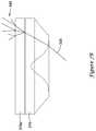
- FIG. 7Bis a cross-sectional view of an illustrative lens and diffuser for illumination of a window mask stencil region of an HVAC controller
- FIG. 7Cis a cross-sectional view of an illustrative lens for illumination of a window mask stencil region of an HVAC controller and the spatial relationship between the lens and a light source;
- FIG. 7Dis a perspective view of an outlet surface of a lens for illuminating a window mask stencil region of an HVAC controller
- FIG. 7Eis a perspective view of an inlet surface of a lens for receiving light from a light source to illuminate a window mask stencil region of an HVAC controller;
- FIGS. 7F-7Hshow various illustrative combinations of lens and diffusers for illuminating a window mask stencil region of an HVAC controller
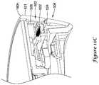
- FIG. 8Ais a perspective view of an illustrative thermistor mount of an HVAC controller
- FIG. 8Bis a perspective view of the position of the illustrative thermistor mount of FIG. 8A relative to a window support of an HVAC controller;
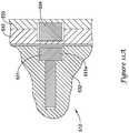
- FIG. 8Cis a cross-sectional view showing the position of the illustrative thermistor mount of FIG. 8A relative to additional components of an HVAC controller;
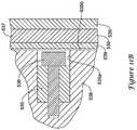
- FIG. 9Ais a cross-sectional view of an illustrative HVAC controller showing an illustrative rotational damping assembly
- FIG. 9Bis a perspective view of illustrative dampeners of the rotational damping assembly of FIG. 9A ;
- FIG. 9Cis an exploded views showing an illustrative method for joining a button light guide assembly to a window support of an HVAC controller
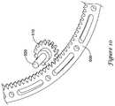
- FIG. 10is a perspective view of an illustrative assembly and method for encoding rotation of a turning ring
- FIG. 10Ais a perspective view of an illustrative code wheel or turning ring
- FIG. 10Bis a perspective view of another illustrative code wheel with a reflective code mounted to an inner extending flange;
- FIG. 10Cis a cross-sectional perspective view of the illustrative code wheel of FIG. 10B mounted in an HVAC controller, such as the HVAC controller of FIG. 4 ;
- FIG. 10Dis a perspective view of a user's finger turning an outer ring of an illustrative HVAC controller, such as the HVAC controller of FIG. 4 ;
- FIG. 11A-Dillustrate several magnetic mounting configurations for mounting a thermostat housing to a thermostat mounting plate
- FIG. 12Aillustrates a battery terminal of the prior art
- FIG. 12Billustrates an improved battery terminal
- FIG. 12Cis a perspective view of the illustrative battery terminal of FIG. 12B installed on a printed wiring board;
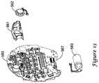
- FIG. 13is a perspective view of an illustrative mounting arrangement for certain components of a printed wiring board of an HVAC controller, such as the HVAC controller of FIG. 4 ;
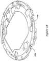
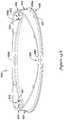
- FIG. 14Ais a perspective view of an illustrative light guide ring for an HVAC controller, such as the HVAC controller of FIG. 4 ;
- FIG. 14Bis a detailed view of a light input region of the light guide ring of FIG. 14A ;
- FIG. 14Cis another detailed view of the light input region of the light guide ring of FIG. 14A ;
- FIG. 14Dis a detailed view of the light extraction region of the light guide ring of FIG. 14A ;
- FIG. 14Eis an elevation view of the light guide ring of FIG. 14A mounted in relation to a printed circuit board;
- FIG. 14Fis a flow diagram showing an illustrative method for illuminating a light guide ring, such as the light guide ring of FIG. 14A ;
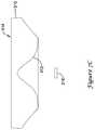
- FIG. 15is an elevation view of the wall side view of a mud ring
- FIG. 15Ais a perspective view of an illustrative wall plate, showing jumper switch actuators that may be used to selectively block access to wiring terminals;
- FIGS. 16A-16Bare a schematic diagram of an illustrative circuit for switching between single transformer and two transformer operation
- FIG. 16Cis a schematic diagram of another illustrative circuit for switching between single transformer and two transformer operation
- FIG. 16Dis a schematic diagram of another illustrative circuit for providing an optional utility terminal
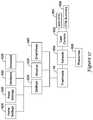
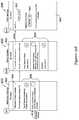
- FIG. 17is a block diagram of principal settings for an illustrative thermostat and its interactions with networked components
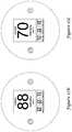
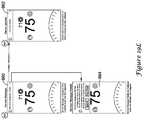
- FIG. 17Ais a front elevation view of the front face of an illustrative thermostat
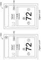
- FIGS. 17B-17Iare front elevation views of the front face of the illustrative thermostat of FIG. 17A under a variety of operating conditions;
- FIGS. 17J-17Lare front elevation views of the front face of the illustrative thermostat of FIG. 17A illustrating optional presentation modes for weather related information
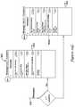
- FIG. 18Ais a block diagram of an illustrative building automation system that utilizes user-defined macros
- FIG. 18Bis a block diagram of a remote user device that can be utilized with the building automation system of FIG. 18A ;
- FIG. 18Cis a flow diagram showing a method that may be carried out using the building automation system of FIG. 18A and the remote user device of FIG. 18B ;
- FIGS. 18D-18Jare an illustrative flow diagram of programming one-touch actions (e.g. macros);
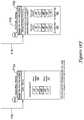
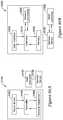
- FIG. 19Ais a block diagram of an illustrative mobile device that can be used to program an illustrative HVAC controller of a building automation system
- FIG. 19Bis a block diagram of another illustrative mobile device that can be used to program an illustrative HVAC controller of a building automation system;
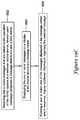
- FIG. 19Cis a flow diagram of an illustrative method that may be carried out using the mobile devices of FIGS. 19A and/or FIG. 19B ;
- FIG. 19D-19Lschematically illustrates the display of messages related to the operation of a thermostat on a mobile device
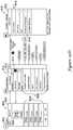
- FIG. 20Ais a block diagram of an illustrative building automation system
- FIG. 20Bis a block diagram of another illustrative building automation system
- FIG. 20Cis a flow diagram of an illustrative method that may be carried out using the illustrative building automation systems of FIGS. 20A and/or FIG. 20B ;
- FIGS. 20D-27show several illustrative screens that may be displayed to a user via the user interface of a mobile device in connection with downloading of an application program code for installing, setting up and configuring an HVAC controller;
- FIG. 28shows an illustrative screen that may be displayed upon successful launch of an application program code for setting up an HVAC controller
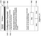
- FIGS. 29-41show illustrative screens that may be displayed on the user interface of a remote device (e.g. mobile device) by an application program code that may guide the user through removal of an existing HVAC controller;
- a remote devicee.g. mobile device
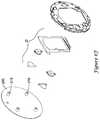
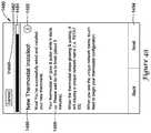
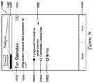
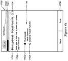
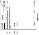
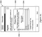
- FIGS. 42-49show illustrative screens that may be displayed on the user interface of a remote device (e.g. mobile device) by an application program code that may guide the user through installation of a new HVAC controller;
- a remote devicee.g. mobile device
- FIG. 50is a front elevation view an illustrative HVAC controller after a successful installation
- FIG. 51shows an illustrative screen that may be displayed on the user interface of a remote device (e.g. mobile device) when the remote device is attempting to connect to a wireless network hosted by an illustrative HVAC controller;
- a remote devicee.g. mobile device
- FIG. 52shows an illustrative screen that may be displayed on the user interface of an illustrative HVAC controller when a remote device (e.g. mobile device) is attempting to connect to a network hosted by the illustrative HVAC controller;
- a remote devicee.g. mobile device
- FIG. 53shows an illustrative screen that may be displayed on the user interface of an illustrative HVAC controller upon successful connection of a remote device to the wireless network hosted by the illustrative HVAC controller 18 ;
- FIG. 54is a schematic diagram of network architecture that may be utilized by an illustrative HVAC controller in communication with a remote device and an external web service;
- FIGS. 55-69show illustrative screens that may be displayed on the user interface of a remote device (e.g. mobile device) by an application program code that may guide the user through configuring an illustrative HVAC controller;
- a remote devicee.g. mobile device
- FIG. 70shows an illustrative screen that may be displayed on the user interface of a remote device by an application program code upon completion of the configuration phase of the setup process
- FIG. 71shows an illustrative screen that may be displayed on the display of the user interface of the HVAC controller that has been configured upon completion of the configuration phase of the setup process;
- FIGS. 72-78show illustrative screens that may be displayed on the user interface of a remote device by an application program code that may guide the user through connecting an HVAC controller to a wireless network and to a web service;
- FIGS. 79-84show illustrative screens that may be displayed on the user interface of a remote device by an application program code that may guide a user through personalizing an illustrative HVAC controller;
- FIG. 85shows an illustrative screen that may be displayed on the display of the user interface of the illustrative HVAC controller that is being setup after completion of the setup process;
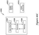
- FIG. 86Ais a schematic block diagram of an illustrative building automation system
- FIG. 86Bis a schematic block diagram of another illustrative building automation system.
- FIG. 86Cis a schematic block diagram of a server of an illustrative building automation system
- FIGS. 86D and 86Eshow illustrative screens that may be displayed on the user interface of a remote device (e.g. mobile device) by an application program code that may guide a user through utilizing certain functions of an HVAC controller;
- a remote devicee.g. mobile device
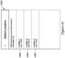
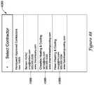
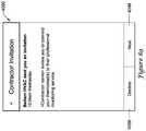
- FIGS. 87-91show illustrative screens that may be displayed on the user interface of a remote device (e.g. mobile device) by an application program code through which a user may identify and connect to an HVAC contractor;
- a remote devicee.g. mobile device
- FIG. 92shows another view of an options screen after a user has connected to an HVAC contractor
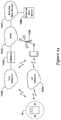
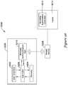
- FIG. 93is a schematic diagram of an illustrative method for utilizing geofencing in a building automation system
- FIG. 94is a schematic block diagram of an illustrative building automation system that may be used with geofencing
- FIG. 95is a schematic block diagram of another building automation system that may be use with geofencing
- FIG. 96is a schematic block diagram of another building automation system that may be use with geofencing
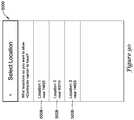
- FIG. 97shows an illustrative screen that may be displayed on the user interface of a remote device (e.g. mobile device) by an application program code through which a user may select between a small and a large proximity boundary setting for geofencing;
- a remote devicee.g. mobile device
- FIGS. 98-101show illustrative screens that may be displayed on the user interface of a remote device (e.g. mobile device) by an application program code that may guide a user through selecting an appropriate proximity boundary;
- a remote devicee.g. mobile device
- FIG. 102shows another illustrative setting screen that may be displayed on the user interface of a remote device (e.g. mobile device) by an application program code through which a user may select an appropriate geofence setting;
- a remote devicee.g. mobile device
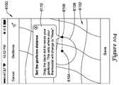
- FIG. 103shows an illustrative screen through which a user may customize a proximity boundary
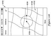
- FIGS. 104-106show illustrative screens through which a user may customize a proximity boundary
- FIG. 107is a schematic block diagram of an illustrative HVAC controller.
- references in the specification to “an embodiment”, “some embodiments”, “other embodiments”, etc.,indicate that the embodiment described may include a particular feature, structure, or characteristic, but every embodiment may not necessarily include the particular feature, structure, or characteristic. Moreover, such phrases are not necessarily referring to the same embodiment. Further, when a particular feature, structure, or characteristic is described in connection with an embodiment, it is contemplated that the feature, structure, or characteristic may be applied to other embodiments whether or not explicitly described unless clearly stated to the contrary.
- Building automation systemsare systems that control one or more operations of a building.
- Building automation systemscan include HVAC systems, security systems, fire suppression systems, energy management systems and other systems. While HVAC systems are used as an example below, it should be recognized that the concepts disclosed herein can be applied to building control systems more generally.
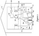
- FIG. 1is a schematic view of a building 2 having an illustrative heating, ventilation, and air conditioning (HVAC) system 4 . While FIG. 1 shows a typical forced air type HVAC system, other types of HVAC systems are contemplated including, but not limited to, boiler systems, radiant heating systems, electric heating systems, cooling systems, heat pump systems, and/or any other suitable type of HVAC system, as desired.
- the illustrative HVAC system 4 of FIG. 1includes one or more HVAC components 6 , a system of ductwork and air vents including a supply air duct 10 and a return air duct 14 , and one or more HVAC controllers 18 .
- the one or more HVAC components 6may include, but are not limited to, a furnace, a heat pump, an electric heat pump, a geothermal heat pump, an electric heating unit, an air conditioning unit, a humidifier, a dehumidifier, an air exchanger, an air cleaner, a damper, a valve, and/or the like.
- the HVAC controller(s) 18may be configured to control the comfort level in the building or structure by activating and deactivating the HVAC component(s) 6 in a controlled manner.
- the HVAC controller(s) 18may be configured to control the HVAC component(s) 6 via a wired or wireless communication link 20 .
- the HVAC controller(s) 18may be a thermostat, such as, for example, a wall mountable thermostat, but this is not required in all embodiments. Such a thermostat may include (e.g. within the thermostat housing) or have access to a temperature sensor for sensing an ambient temperature at or near the thermostat.
- the HVAC controller(s) 18may be a zone controller, or may include multiple zone controllers each monitoring and/or controlling the comfort level within a particular zone in the building or other structure.
- the HVAC component(s) 6may provide heated air (and/or cooled air) via the ductwork throughout the building 2 .
- the HVAC component(s) 6may be in fluid communication with every room and/or zone in the building 2 via the ductwork 10 and 14 , but this is not required.
- an HVAC component 6e.g. forced warm air furnace
- the heated airmay be forced through supply air duct 10 by a blower or fan 22 .
- the cooler air from each zonemay be returned to the HVAC component 6 (e.g. forced warm air furnace) for heating via return air ducts 14 .
- an HVAC component 6e.g. air conditioning unit
- the cooled airmay be forced through supply air duct 10 by the blower or fan 22 .
- the warmer air from each zonemay be returned to the HVAC component 6 (e.g. air conditioning unit) for cooling via return air ducts 14 .
- the HVAC system 4may include an internet gateway or other device 23 that may allow one or more of the HVAC components, as described herein, to communicate over a wide area network (WAN) such as, for example, the Internet.
- WANwide area network
- the system of vents or ductwork 10 and/or 14can include one or more dampers 24 to regulate the flow of air, but this is not required.
- one or more dampers 24may be coupled to one or more HVAC controller(s) 18 , and can be coordinated with the operation of one or more HVAC components 6 .
- the one or more HVAC controller(s) 18may actuate dampers 24 to an open position, a closed position, and/or a partially open position to modulate the flow of air from the one or more HVAC components to an appropriate room and/or zone in the building or other structure.
- the dampers 24may be particularly useful in zoned HVAC systems, and may be used to control which zone(s) receives conditioned air from the HVAC component(s) 6 .
- one or more air filters 30may be used to remove dust and other pollutants from the air inside the building 2 .
- the air filter(s) 30is installed in the return air duct 14 , and may filter the air prior to the air entering the HVAC component 6 , but it is contemplated that any other suitable location for the air filter(s) 30 may be used.
- the presence of the air filter(s) 30may not only improve the indoor air quality, but may also protect the HVAC components 6 from dust and other particulate matter that would otherwise be permitted to enter the HVAC component.
- the illustrative HVAC system 4may include an equipment interface module (EIM) 34 .
- the equipment interface module 34may, in addition to controlling the HVAC under the direction of the thermostat, be configured to measure or detect a change in a given parameter between the return air side and the discharge air side of the HVAC system 4 .
- the equipment interface module 34may measure a difference in temperature, flow rate, pressure, or a combination of any one of these parameters between the return air side and the discharge air side of the HVAC system 4 .
- the equipment interface module 34may be adapted to measure the difference or change in temperature (delta T) between a return air side and discharge air side of the HVAC system 4 for the heating and/or cooling mode.
- the equipment interface module 34may include a first temperature sensor 38 a located in the return (incoming) air duct 14 , and a second temperature sensor 38 b located in the discharge (outgoing or supply) air duct 10 .
- the equipment interface module 34may include a differential pressure sensor including a first pressure tap 39 a located in the return (incoming) air duct 14 , and a second pressure tap 39 b located downstream of the air filter 30 to measure a change in a parameter related to the amount of flow restriction through the air filter 30 .
- the equipment interface module 34when provided, may include at least one flow sensor that is capable of providing a measure that is related to the amount of air flow restriction through the air filter 30 .
- the equipment interface module 34may include an air filter monitor. These are just some examples.
- the equipment interface module 34may be configured to communicate with the HVAC controller 18 via, for example, a wired or wireless communication link 42 .
- the equipment interface module 34may be incorporated or combined with the HVAC controller 18 .
- the equipment interface module 34may communicate, relay or otherwise transmit data regarding the selected parameter (e.g. temperature, pressure, flow rate, etc.) to the HVAC controller 18 .
- the HVAC controller 18may use the data from the equipment interface module 34 to evaluate the system's operation and/or performance.
- the HVAC controller 18may compare data related to the difference in temperature (delta T) between the return air side and the discharge air side of the HVAC system 4 to a previously determined delta T limit stored in the HVAC controller 18 to determine a current operating performance of the HVAC system 4 .
- delta Tdifference in temperature
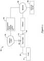
- FIG. 2is a schematic view of an HVAC control system 50 that facilitates remote access and/or control of the HVAC system 4 shown in FIG. 1 .
- the HVAC control system 50may be considered a building control system or part of a building control system.
- the illustrative HVAC control system 50includes an HVAC controller, as for example, HVAC controller 18 (see FIG. 1 ) that is configured to communicate with and control one or more HVAC components 6 of the HVAC system 4 .
- the HVAC controller 18may communicate with the one or more HVAC components 6 of the HVAC system 4 via a wired or wireless link.
- the HVAC controller 18may communicate over one or more wired or wireless networks that may accommodate remote access and/or control of the HVAC controller 18 via another device such as a smart phone, tablet, e-reader, laptop computer, personal computer, key fob, or the like.
- the HVAC controller 18may include a first communications port 52 for communicating over a first network 54 , and in some cases, a second communications port 56 for communicating over a second network 58 .
- the first network 54may be a wireless local area network (LAN), and the second network 58 (when provided) may be a wide area network or global network (WAN) including, for example, the Internet.
- LANwireless local area network
- WANglobal network
- the wireless local area network 54may provide a wireless access point and/or a network host device that is separate from the HVAC controller 18 . In other cases, the wireless local area network 54 may provide a wireless access point and/or a network host device that is part of the HVAC controller 18 . In some cases, the wireless local area network 54 may include a local domain name server (DNS), but this is not required for all embodiments. In some cases, the wireless local area network 54 may be an ad-hoc wireless network, but this is not required.
- DNSlocal domain name server
- the HVAC controller 18may be programmed to communicate over the second network 58 with an external web service hosted by one or more external web server 66 .
- an external web serviceis Honeywell's TOTAL CONNECTTM web service.
- the HVAC controller 18may be configured to upload selected data via the second network 58 to the external web service where it may be collected and stored on the external web server 66 . In some cases, the data may be indicative of the performance of the HVAC system 4 . Additionally, the HVAC controller 18 may be configured to receive and/or download selected data, settings and/or services sometimes including software updates from the external web service over the second network 58 .
- the data, settings and/or servicesmay be received automatically from the web service, downloaded periodically in accordance with a control algorithm, and/or downloaded in response to a user request.
- the HVAC controller 18may be configured to receive and/or download an HVAC operating schedule and operating parameter settings such as, for example, temperature set points, humidity set points, start times, end times, schedules, window frost protection settings, and/or the like from the web server 66 over the second network 58 .
- the HVAC controller 18may be configured to receive one or more user profiles having at least one operational parameter setting that is selected by and reflective of a user's preferences.
- the HVAC controller 18may be configured to receive and/or download firmware and/or hardware updates such as, for example, device drivers from the web server 66 over the second network 58 . Additionally, the HVAC controller 18 may be configured to receive local weather data, weather alerts and/or warnings, major stock index ticker data, and/or news headlines over the second network 58 . These are just some examples.
- remote access and/or control of the HVAC controller 18may be provided over the first network 54 and/or the second network 58 .
- a variety of remote wireless devices 62may be used to access and/or control the HVAC controller 18 from a remote location (e.g. remote from the HVAC Controller 18 ) over the first network 54 and/or second network 58 including, but not limited to, mobile phones including smart phones, tablet computers, laptop or personal computers, wireless network-enabled key fobs, e-readers, and/or the like.
- the remote wireless devices 62are configured to communicate wirelessly over the first network 54 and/or second network 58 with the HVAC controller 18 via one or more wireless communication protocols including, but not limited to, cellular communication, ZigBee, REDLINKTM, Bluetooth, WiFi, IrDA, dedicated short range communication (DSRC), EnOcean, and/or any other suitable common or proprietary wireless protocol, as desired.
- wireless communication protocolsincluding, but not limited to, cellular communication, ZigBee, REDLINKTM, Bluetooth, WiFi, IrDA, dedicated short range communication (DSRC), EnOcean, and/or any other suitable common or proprietary wireless protocol, as desired.
- an application program codestored in the memory of the remote device 62 may be used to remotely access and/or control the HVAC controller 18 .
- the application program code (app)may be provided for downloading from an external web service, such as the web service hosted by the external web server 66 (e.g. Honeywell's TOTAL CONNECTTM web service) or another external web service (e.g. ITUNES® or Google Play).
- the appmay provide a remote user interface for interacting with the HVAC controller 18 at the user's remote device 62 .
- a usermay be able to change the operating schedule and operating parameter settings such as, for example, temperature set points, humidity set points, start times, end times, schedules, window frost protection settings, accept software updates and/or the like.
- Communicationsmay be routed from the user's remote device 62 to the web server 66 and then, from the web server 66 to the HVAC controller 18 .
- communicationsmay flow in the opposite direction such as, for example, when a user interacts directly with the HVAC controller 18 to change an operating parameter setting such as, for example, a schedule change or a set point change.
- the change made at the HVAC controller 18may then be routed to the web server 66 and then from the web server 66 to the remote device 62 where it may reflected by the application program executed by the remote device 62 .
- a usermay be able to interact with the HVAC controller 18 via a user interface provided by one or more web pages served up by the web server 66 .
- the usermay interact with the one or more web pages using a variety of internet capable devices to effect a change at the HVAC controller 18 as well as view usage data and energy consumption date related to the usage of the HVAC system 4 .
- communicationmay occur between the user's remote device 62 and the HVAC controller 18 without being relayed through a server.
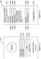
- FIG. 3is an illustrative schematic block diagram of the HVAC controller 18 of FIG. 2 .
- the HVAC controller 18may be accessed and/or controlled from a remote location over the first network 54 and/or the second network 58 using a remote wireless device 62 such as, for example, a smart phone, a tablet computer, a laptop or personal computer, a wireless network-enabled key fob, an e-reader, and/or the like.
- the HVAC controller 18may be a thermostat, but this is not required.
- the HVAC controller 18may include a communications block 60 having a first communications port 52 for communicating over a first network (e.g.
- the first communications port 52can be a wireless communications port including a wireless transceiver for wirelessly sending and/or receiving signals over a first wireless network 54 .
- the second communications port 56may be a wireless communications port including a wireless transceiver for sending and/or receiving signals over a second wireless network 58 .
- the second communications port 56may be in communication with a wired or wireless router or gateway for connecting to the second network, but this is not required.
- the router or gatewaymay be integral to the HVAC controller 18 or may be provided as a separate device.
- the illustrative HVAC controller 18may include a processor (e.g. microprocessor, microcontroller, etc.) 64 and a memory 72 .
- the HVAC controller 18may also include a user interface 108 , but this is not required.
- HVAC controller 18may include a timer (not shown). The timer may be integral to the processor 64 or may be provided as a separate component.
- the memory 72 of the illustrative HVAC controller 18may be in communication with the processor 64 .
- the memory 72may be used to store any desired information, such as the aforementioned control algorithm, set points, schedule times, diagnostic limits such as, for example, differential pressure limits, delta T limits, and the like.
- the memory 72may be any suitable type of storage device including, but not limited to, RAM, ROM, EPROM, flash memory, a hard drive, and/or the like.
- the processor 64may store information within the memory 72 , and may subsequently retrieve the stored information from the memory 72 .
- the HVAC controller 18may include an input/output block (I/O block) 78 having a number of wire terminals (e.g. 80 a - 80 c ) for receiving one or more signals from the HVAC system 4 and/or for providing one or more control signals to the HVAC system 4 .
- the I/O block 78may communicate with one or more HVAC components 6 of the HVAC system 4 .
- the HVAC controller 18may have any number of wire terminals for accepting a connection from one or more HVAC components 6 of the HVAC system 4 . However, how many wire terminals are utilized and which terminals are wired is dependent upon the particular configuration of the HVAC system 4 . Different HVAC systems 4 having different HVAC components and/or type of HVAC components 6 may have different wiring configurations.
- an I/O block having four wire terminalsis just one example and is not intended to be limiting.
- the I/O block 78may communicate with another controller, which is in communication with one or more HVAC components of the HVAC system 4 , such as a zone control panel in a zoned HVAC system, equipment interface module (EIM) (e.g. EIM 34 shown in FIG. 1 ) or any other suitable building control device.
- EIMequipment interface module
- a power-transformation block 82may be connected to one or more wires of the I/O block 78 , and may be configured to bleed or steal energy from the one or more wires of the I/O block 78 .
- the power bled off of the one or more wires of the I/O blockmay be stored in an energy storage device 86 that may be used to at least partially power the HVAC controller 18 .
- the energy storage device 86may be capacitor or a rechargeable battery.
- the HVAC controller 18may also include a back-up source of energy such as, for example, a battery that may be used to supplement power supplied to the HVAC controller 18 when the amount of available power stored by the energy storage device 86 is less than optimal or is insufficient to power certain applications. Certain applications or functions performed by the HVAC controller may require a greater amount of energy than others. If there is an insufficient amount of energy stored in the energy storage device 86 , then, in some cases, certain applications and/or functions may be prohibited by the processor 64 .
- the HVAC controller 18may also include one or more sensors such as for example, a temperature sensor, a humidity sensor, an occupancy sensor, a proximity sensor, and/or the like. In some cases, the HVAC controller 18 may include an internal temperature sensor 90 , as shown FIG. 3 , but this is not required. The HVAC controller 18 may also communicate with one or more remote temperature sensors, humidity sensors, and/or occupancy sensors located throughout the building or structure. Additionally, the HVAC controller may communicate with a temperature sensor and/or humidity sensor located outside of the building or structure for sensing an outdoor temperature and/or humidity if desired.
- sensorssuch as for example, a temperature sensor, a humidity sensor, an occupancy sensor, a proximity sensor, and/or the like. In some cases, the HVAC controller 18 may include an internal temperature sensor 90 , as shown FIG. 3 , but this is not required. The HVAC controller 18 may also communicate with one or more remote temperature sensors, humidity sensors, and/or occupancy sensors located throughout the building or structure. Additionally, the HVAC controller may communicate with a temperature sensor and/or humidity sensor located outside of the building
- the HVAC controller 18may include a sensor 92 that is configured determine if a user is in proximity to the building controller.
- the sensor 92may be a motion sensor or a proximity sensor such as, for example, a passive infrared (PIR) sensor.
- PIRpassive infrared
- the sensor 92may be located remotely from the HVAC controller 18 and may be in wireless communication with the HVAC controller 18 via one of the communication ports.
- the sensor 92may be configured to determine that the user is near or expected to be near the HVAC controller 18 based, at least in part, on the location data provided by a location based service application program executed by a user's remote device 62 that the user utilizes to interact with the HVAC controller 18 from a remote location.
- the location data generated by the location based services appmay be transmitted from the user's remote device 62 directly to the HVAC controller 18 or, in some cases, may be transmitted to the HVAC controller 18 via a server 66 (e.g. Honeywell's TOTAL CONNECTTM server) to which both the HVAC controller 18 and the user's remote device 62 may be connected.
- a server 66e.g. Honeywell's TOTAL CONNECTTM server
- the sensor 92may be configured to determine that the user or, more specifically, the user's remote device 62 has crossed at least one of two or more proximity boundaries relative to the location of the HVAC controller 18 based on location data provided by the user's remote device that the user utilizes to interact with the HVAC controller 18 .
- the user's remote device 62may determine that the user has crossed a proximity boundary by comparing the location data generated by sensor 92 of the user's remote device 62 to a predetermined fixed location or boundary.
- the proximity boundary(s)may be defined by a radius extending outward from a predetermined fixed location.
- the predetermined fixed locationmay be the location of the HVAC controller 18 or another selected location such as, for example, the user's workplace.
- the proximity boundary(s)may be customized by the user and may have any shape and or size that appropriately reflects the user's local and/or daily travel habits.
- at least one proximity boundarymay be configured by the user to have the same general size and/or shape of the city in which their home or workplace is located.
- the sensor 92may be configured to determine that the user is in proximity to or is expected to be in proximity to the HVAC controller 18 upon detecting that the user's remote device 62 is connected to the building's wireless network which, in some cases, may be the same network to which the HVAC controller 18 is also connected.
- Such functionalityis shown and described in U.S. Patent Publication No. 2014/0031989 entitled “HVAC CONTROLLER WITH WIRELESS NETWORK BASED OCCUPANCY DETECTION AND CONTROL”, the entirety of which is incorporated by reference herein for all purposes.
- the user's remote device 62may be configured to determine that a user is in proximity to the HVAC controller 18 upon sensing a user's interaction with the HVAC controller 18 via the user interface provided at the HVAC controller 18 .
- the sensor 92may be configured to sense when the screen of the user interface 108 is touched and/or when a button provided at the user interface 108 is pressed by a user.
- the sensor 92may be a touch sensitive region provided on the user interface 108 when the user interface 108 incorporates a touch screen display.
- the sensor 92may be associated with a hard button or soft key that is provided separate from a display of the user interface 108 .
- the sensor 92may deliver a signal to the processor 64 indicating that the user is in proximity to the HVAC controller 18 . In other cases, the upon detecting or determining that a user is in proximity to the HVAC controller 18 , the sensor 92 may be configured to transmit a signal to a remote server 66 over a second network 58 via the communications block 60 .
- the user interface 108when provided, may be any suitable user interface that permits the HVAC controller 18 to display and/or solicit information, as well as accept one or more user interactions with the HVAC controller 18 .
- the user interface 108may permit a user to locally enter data such as temperature set points, humidity set points, starting times, ending times, schedule times, diagnostic limits, responses to alerts, and the like.
- the user interface 108may be a physical user interface that is accessible at the HVAC controller 18 , and may include a display and/or a distinct keypad.
- the displaymay be any suitable display.
- a displaymay include or may be a liquid crystal display (LCD), and in some cases an e-ink display, fixed segment display, or a dot matrix LCD display.
- LCDliquid crystal display
- the user interface 108may be a touch screen LCD panel that functions as both display and keypad.
- the touch screen LCD panelmay be adapted to solicit values for a number of operating parameters and/or to receive such values, but this is not required.
- the user interface 108may be a dynamic graphical user interface.
- the user interface 108need not be physically accessible to a user at the HVAC controller 18 .
- the user interface 108may be a virtual user interface 108 that is accessible via the first network 54 and/or second network 58 using a mobile wireless device such as one of those remote devices 62 previously described herein.
- the virtual user interface 108may be provided by an app executed by a user's remote device for the purposes of remotely interacting with the HVAC controller 18 .
- the usermay change temperature set points, humidity set points, starting times, ending times, schedule times, diagnostic limits, respond to alerts, update their user profile, view energy usage data, and/or the like.
- changes made to the HVAC controller 18 via a user interface 108 provided by an app on the user's remote device 62may be first transmitted to an external web server 66 .
- the external web server 66may receive and accept the user inputs entered via the virtual user interface 108 provided by the app on the user's remote device 62 , and associate the user inputs with a user's account on the external web service.
- the external web server 66may update the control algorithm, as applicable, and transmit at least a portion of the updated control algorithm over the second network 58 to the HVAC controller 18 where it is received via the second port 56 and may be stored in the memory 72 for execution by the processor 64 . In some cases, the user may observe the effect of their inputs at the HVAC controller 18 .
- the communication rate between the processor 64 and the web server 66may affect the message latency from when the user interacts with the user interface 108 provided by their remote device 62 to effect a change at the HVAC controller 18 and when a message corresponding to the user's interaction with the user interface 108 provided at their remote device 62 is communicated to the HVAC controller 18 .
- the usermay experience lower message latencies when the HVAC controller 18 has a full amount of available power stored in the energy storage device.
- the message latencymay increase as less power is available to the HVAC controller 18 from the energy storage device 86 , but this is not required.
- the virtual user interface 108may include one or more web pages that are transmitted over the second network 58 (e.g. WAN or the Internet) by an external web server (e.g. web server 66 ).
- the one or more web pages forming the virtual user interface 108may be hosted by an external web service and associated with a user account having one or more user profiles.
- the external web server 66may receive and accept user inputs entered via the virtual user interface and associate the user inputs with a user's account on the external web service.
- the external web server 66may update the control algorithm, as applicable, and transmit at least a portion of the updated control algorithm over the second network 58 to the HVAC controller 18 where it is received via the second port 56 and may be stored in the memory 72 for execution by the processor 64 . In some cases, the user may observe the effect of their inputs at the HVAC controller 18 .
- a usermay use either the user interface 108 provided at the HVAC controller 18 and/or a virtual user interface 108 as described herein.
- the two types of user interfaces 108 that may be used to interact with the HVAC controller 18are not mutually exclusive of one another.
- a virtual user interface 108may provide more advanced capabilities to the user.
- FIG. 4is a front elevation view of an illustrative HVAC controller 18 that includes a user interface 108 .
- the user interface 108provided at the HVAC controller 18 , may be provided in addition to or in alternative to a virtual user interface that may be provided by an application program executed by a user's remote device 62 or that may be viewed as one or more web pages served up by a web server 66 , as discussed herein.
- the illustrative user interface 108may include a display 94 disposed within a housing 96 .
- the display 94may be a touch screen display, but this is not required.
- the user interface 108may include one or more touch sensitive regions 98 a - 98 c provided on the display 94 , each touch sensitive region defining a button through which the user may interact with the HVAC controller 18 . Additionally, or alternatively, the user interface 108 may include one or more buttons 102 a and 102 b that may be provided separate from the display 94 through which the user may interact with the HVAC controller 18 . In some cases, the buttons 102 a , 102 b may be touch sensitive capacitive buttons. In other cases, the buttons 102 a , 102 b may be hard, physical buttons or soft keys. It will be generally understood that the size and shape of the display as well as the number and location of the various buttons can vary.
- the housing 96may be fabricated from any suitable material. As shown in FIG. 4 , the housing 96 may have a generally circular foot print, but this is not required. In some cases, the housing 96 may be a two-part housing a may include a rotating ring 106 which may form part of the user interface 108 , and which may provide another mechanism for accepting input from a user. For example, the user may rotate the ring 106 to increase or decrease an operating parameter (e.g. set point) and/or to change information viewed on the display 94 by advancing from a first screen to a second screen displayed on the display 94 .
- an operating parametere.g. set point
- a more advanced or detailed user interface 108 for more fully interacting with the HVAC controller 18may be provided by an application program executed at a user's remote device 62 and/or by one or more web pages served up by a web server such as web server 66 , as described herein.
- the processor 64may operate in accordance with an algorithm that controls or at least partially controls one or more HVAC components of an HVAC system such as, for example, HVAC system 4 of FIG. 1 .
- the processor 64may operate in accordance with a control algorithm that provides temperature set point changes, humidity set point changes, schedule changes, start and end time changes, window frost protection setting changes, operating mode changes, and/or the like.
- At least a portion of the control algorithmmay be stored locally in the memory 72 of the HVAC controller 18 and, in some cases, may be received from an external web service over the second network 58 .
- the control algorithm (or portion thereof) stored locally in the memory 72 of the HVAC controller 18may be periodically updated in accordance with a predetermined schedule (e.g.
- control algorithme.g. set point change
- the updates to the control algorithm or portion of the control algorithm stored in the memory 72may be received from an external web service over the second network.
- the control algorithmmay include settings such as set points.
- the processor 64may operate according to a first operating mode having a first temperature set point, a second operating mode having a second temperature set point, a third operating mode having a third temperature set point, and/or the like.
- the first operating modemay correspond to an occupied mode
- the second operating modemay correspond to an unoccupied mode.
- the third operating modemay correspond to a holiday or vacation mode wherein the building or structure in which the HVAC system 4 is located may be unoccupied for an extended period of time.
- the third operating modemay correspond to a sleep mode wherein the building occupants are either asleep or inactive for a period of time. These are just some examples. It will be understood that the processor 64 may be capable of operating in additional operating modes as necessary or desired.
- the number of operating modes and the operating parameter settings associated with each of the operating modesmay be established locally through the user interface 108 , and/or through an external web service and delivered to the HVAC controller via the second network 58 where they may be stored in the memory 72 for reference by the processor 64 .
- the processor 64may operate according to one or more predetermined operating parameter settings associated with a user profile for an individual user.
- the user profilemay be stored in the memory 72 of the HVAC controller 18 and/or may be hosted by an external web service and stored on an external web server.
- the user profilemay include one or more user-selected settings for one or more operating modes that may be designated by the user.
- the processor 64may operate according to a first operating mode having a first temperature set point associated with a first user profile, a second operating mode having a second temperature set point associated with the first user profile, a third operating mode having a third temperature set point associated with the first user profile, and/or the like.
- the first operating modemay correspond to an occupied mode
- the second operating modemay correspond to an unoccupied mode
- the third operating modemay correspond to a vacation or extended away mode wherein the building or structure in which the HVAC system 4 is located may be unoccupied for an extended period of time.
- multiple user profilesmay be associated with the HVAC controller 18 .
- the processor 64may be programmed to include a set of rules for determining which individual's user profile takes precedence for controlling the HVAC system when both user profiles are active.
- the processor 64may be programmed to execute a guided set-up routine that may guide a user through configuring the HVAC controller 18 to control one or more HVAC components 6 of their particular HVAC system 4 .
- the usermay have limited knowledge about the particular HVAC system configuration.
- the guided set-up routinemay be configured to guide a user through set-up of the HVAC controller 18 without requiring detailed knowledge of the particular HVAC system and/or without requiring the user to consult a technical manual or guide.
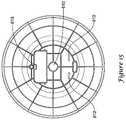
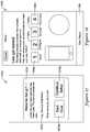
- FIG. 5serves to indicate the relative locations of components of one illustrative embodiment. It will be appreciated that certain of the components may be omitted, combined, rearranged, or otherwise modified in other embodiments.
- window display mask 200 of FIG. 6Amay allow selected display components to be seen through the window display mask 200 to effect a uniform display appearance as well as to alter the apparent shape(s) of the elements of the overall display without requiring custom display elements.
- the display windowitself may be fabricated from any convenient transparent material such glass, polycarbonate, acrylic, or the like.
- the window display mask 200is formed on the inner surface of the display window and is carefully registered with display elements of the thermostat.
- the window display mask 200may be formed by conventional techniques and the opaque regions of the window display mask may be colored black, white, or other colors.
- the window display maskmay be formed of a material which is largely transparent when backlit and which presents a mirror finish when not backlit.
- the portions of the window display mask which are formed of a material which is largely transparent when backlitmay be confined to those portions of the window display mask which are not opaque.
- the material which is largely transparent when backlitmay include a metallized layer which is substantially nonconductive to minimize interference with radio frequency communication between the thermostat and other components of the system.
- the material which is largely transparent when backlitmay be applied to the inner surface of the transparent material before the mask 200 is applied. This material may also be used as a component of an optical encoder associated with sensing motion and or position of a code wheel or turning ring (see 180 h of FIG. 5 ), but this is not required.
- Some portions and apertures 220 a - b of the window display mask 200may overlie a single display element, such as a rectangular color LED display of FIG. 5 e , so that the user experiences that portion of the color LED display which is seen through aperture 220 b as a circular screen element and experiences the arched aperture 220 a as a separate arched display element or elements.
- the areas displayed through apertures 220 a - b of the window display mask 200may be further divided into visually distinct display regions such as three user buttons in the area of arched aperture 220 a and/or lists in aperture 220 b .
- the visual information displayed within an aperturemay change from time-to-time depending upon the state of the thermostat.
- the information displayed through aperture 220 bmay alternate between the current time and the current temperature.
- the displaymay provide the current indoor temperature and the current set point through aperture 220 b , if those temperatures differ.
- the information displayedmay include a list of options from which the user may select using a touch screen capability of the device.
- the information displayed through the upper aperture 220 amay represent an array of choices such system mode a setting of Heat, Off, Cool, and optionally may change to a centered indication of the selected choice at a fifth time.
- the display through aperture 220 bmay indicate a portion of the pending changes to the list of set point options.
- circular aperture 220 b and the arched aperture 220 a configurationsare only illustrative and non-limiting and may be replaced by more or fewer mask apertures, said apertures having any desired shape(s).
- certain display elementsmay be implemented as stencils 102 a , 102 b overlying a light source which back illuminates the stencil when the associated function is available and/or active and which is dark or grayed when the function is unavailable and/or inactive. Additional information may be conveyed by selecting from among multiple colored light sources.
- stencil 102 amay overlie a touch-sensitive element such as capacitive touch-sensitive membrane to request local weather information and the information retrieved by the thermostat may be displayed with color coding of light displayed through the aperture or may be displayed in greater detail through the central aperture 220 b .
- one or both touch-sensitive elements associated, for example, with stencil areas 102 a and/or 102 bmay cause one or more options to be displayed and/or selected on the portion of the display visible through aperture 220 b.
- the window and display mask 200may be positioned relative to regions 222 a , 232 a - b (which are on the transparent touch-sensitive element 240 , see subassembly 180 c of FIG. 5 ), and are held in registry with the display (not shown in this figure for clarity) by an appropriate adhesive or other mounting fixture.
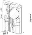
- an air gap 244may be introduced between the front surface of the display and the back surface of the touch sensitive element 240 associated therewith by a perimeter spacer 248 (See FIG. 6C ).
- the air gap 244is believed to enhance the performance of the touch sensitive element 240 and also to help reduce radio frequency noise introduced into the touch sensitive element 240 by the display.
- the air gap 244may be employed with or without a touch sensitive element 240 ground plane formed on the back surface of the touch sensitive element 240 and separated therefrom by a dielectric spacer 207 .
- touch-sensitive element 240may be adhesively attached to the display and button light guide assemblies which are also coupled to window support 250 (see, FIG. 5 , element 1800 ).
- Aperture 220 in the window support 250is aligned with touch sensitive button areas 222 a and an upper portion of the display.
- Aperture 220is also aligned with a touch sensitive region of the touch-sensitive element 240 and overlies a lower portion of the display.
- Stencil aperture 102 ais aligned with a touch-sensitive region 232 a and overlies an illumination source (not shown in this view).
- stencil aperture 102 bis aligned with a touch-sensitive region 232 b and overlies an illumination source (not shown in this view).
- Window support 250 and adhesivemay maintain the window and mask 200 in the desired relationship to other elements of the device and may include appropriate apertures for mounting the display and the illumination sources.
- a mask having generally the same apertures and visual features as described abovemay be formed on the outer surface of the window.
- the maskmay be applied by any of the standard techniques including, but not limited to lamination or in-mold application.
- other components of the thermostatmay be attached to the inner surface of the window without adversely affecting appearance.
- the molded window and associated mask 200may include bosses 215 such as are shown in FIG. 6B .
- the bosses 215like the window support 250 described above, may serve as an assembly framework which is configured to receive a stacked array of relatively stationary components of the thermostat.
- the bosses 215may be asymmetrically disposed and/or may differ in size or shape to help ensure that subsequently added components during assembly are assembled in the correct front side/backside orientation.
- one or more of the bossesmay be tapered and/or stepped to ensure that the order of added components is correct during assembly.
- the inner surface of the windowmay be relieved, for example, to provide a thin section through which an IR sensor may view the room for occupant presence and/or motion with minimal attenuation of the signal by the material of the window when delivered to an optical element 210 that is associated with the IR sensor.
- the window and maskmay include an aperture that is in registration with an optical element 210 that is associated with an IR sensor.
- the programmable thermostatmay be configured to become activated and powered when it senses the presence of a person in front of the programmable thermostat.
- This detectionmay be provided by a passive infrared sensor (PIR) and an associated optical element 210 .
- the sensormay detect thermal radiation of a human body (5-12 micrometers—infrared area [IR]).
- the sensormay include two separate detector pads. A signal may be generated based on a time-based change of thermal radiation received by the two separate detector pads.
- the IR wavelengths of interestare typically blocked by most common optic materials.
- One suitable material for an optical window and/or lensmay be polyethylene (PE). Glass substantially blocks the wavelengths of interest and so glass windows may need to have an aperture to accommodate a proximity sensor and its lens.
- a suitable lenseither positioned in the hole of a glass window or behind a thinned section of a window, may incorporate sloped front surfaces and a corresponding convex rear surface to impart a degree of directionality to the field(s) of view of the sensor.
- the use of Fresnel lens designsmay be desirable to increase the amount of IR energy which reaches the sensor.
- the light gathering surfacesmay desirably differ in size to compensate for transmission differences to equalize sensitivity in different directions. While IR sensors are disclosed here as one example, it is contemplated that any suitable sensor may be used, as desired.
- the capacitive touch elementmay be adhered to the masked window 200 as shown in FIG. 6F .
- a display element group “D”may be located between the window and the button light guide assembly/dampener 180 g which is positioned by the bosses 215 .
- the touch sensitive element(s) of the thermostatmay each be implemented as a separate element, or may be provided with two or more touch sensitive regions.
- the touch sensitive elementmay be formed from a piece of flexible printed circuit material, which is folded into a U-shape and adhered to opposite sides of a transparent dielectric spacer 207 as may be seen in enlarged detail A of FIG. 6E .
- a first half of the flexible printed circuit materialmay form a solid ground plane extending over substantially the entire surface of the dielectric layer 207 .
- the second half of the flexible printed circuit materialmay form the capacitive elements of the touch sensitive assembly, which may serve as the functional buttons, as well as a generalized touch sensitive region associated with the active portions of the display.
- the touch sensitive assemblymay be adhered to the window and spaced a short distance from the face of the display to improve sensitivity and reduce noise.
- Backlightssuch as LED backlights may be used to illuminate the stencil apertures in the window display mask for window 180 a of FIG. 5 .
- a three color LEDmay be mated with a custom lens and a diffuser to provide a relatively hot-spot free illumination from LED arrays mounted on a printed wiring board, 180 j of FIG. 5 .
- the area to be illuminatedis 14 mm in diameter and is located 6 mm from the printed wiring board.
- lens 310may be mounted to the window support 180 f of FIG. 5 at locations 311 and over the LED(s) 320 on the printed wiring board.
- the lens 310is combined with a diffuser 310 a .
- the LED array(or single LED) may produce light with a distribution cone angle of about 120 degrees which generally corresponds to the desired light output angle from the system.
- An illustrative ray 330has been traced through the lens and the diffuser 310 a with a resulting output cone 340 .
- Textured and non-textured diffusers formed from polyethylene terephthalate (PET), acrylics, or acetal, each with thicknesses between 0.17 millimeters (mm) and 1.7 mm,have been shown to be functional with good wide angle light output when the film is translucent and/or textured.
- the lens 310may be formed from a translucent or milky material thus combining the light capture/distribution functions with diffusive scattering.
- FIG. 7Cillustrates a lens 310 , shown in cross-section, which has an optionally surface-textured inlet surface 312 and an optionally surface-textured outlet surface 314 .
- the position of the light source, such as an LED,is indicated by reference numeral 316 .
- FIGS. 7D and 7Eprovide perspective views of an illustrative lens 310 output surface and input surface respectively, as well as the associated mounting structures 315 .
- FIGS. 7F-7Hillustrate various illustrative combinations of a lens 310 and a diffusion component 312 .
- FIG. 7Fshows a lens with a thick diffuser.
- FIG. 7Gshows a lens with a thin diffuser.
- FIG. 7Hshows a lens with an integral or combined diffuser.
- a thermostatFor a thermostat, it is often important to have an accurate indication of the ambient air temperature surrounding the thermostat.
- a thermostatthat includes active electronics in a housing that has a sealed appearance, it can be difficult to position a temperature sensor within the device where the influence of internally generated heat is minimized and where motion of housing components does not complicate connecting the sensor to an appropriate PWB or daughter board.
- the fixed windowis an attractive locale.
- a thermistormay be thermally bonded to the inside surface of the fixed window with a thermal grease to help overcome the variations in positioning which may result from the assembly process.
- a temperature sensorsuch as thermistor 403 a is mounted on a flexible circuit member 403 ( FIG. 8A ) extending from daughterboard 403 b , which is connected in turn to the printed wiring board 180 j of FIG. 5 by connector 405 as illustrated in FIG. 8B .
- the daughterboard 403 bmay be mounted to window support 401 (see, 180 f of FIG. 5 ) such that the circuit member 403 , extending from daughterboard 403 b , is inserted into an isolation pocket formed between window 404 , the window support 401 , and other internal structure(s) such as, for example dampener 402 as may be seen in FIG. 8C .
- window 404may be considered as providing an outer housing wall 406 such that a pocket 408 is formed behind the outer housing wall 406 .
- Daughterboard 403 bmay extend beyond dampener 402 into pocket 408 .
- thermistor 403 ais thermally connected to outer housing wall 406 and is thermally isolated from the rest of the interior of the thermostat. It will be appreciated that the thermostat includes a plurality of heat producing components, and the thermistor 403 a is positioned within pocket 408 such that thermistor 403 a is isolated from the plurality of heat producing components.
- contacts between the pocket forming structures and the flexible circuit member 403flex the flexible circuit member mounted thermistor 403 a against the window 404 , reducing or eliminating the need for manual positioning of a lead mounted thermistor 403 a and the need for thermal contact grease.
- flexible circuit member 403is configured to provide a bias force toward a non-flexed state when flexed. In some embodiments, the bias force of flexible circuit member 403 biases the thermistor 403 a against outer housing wall 406 .
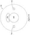
- a rotatable ringmay form part of the outer surface of the HVAC controller.
- an optical encodersuch as a reflective optical encoder, may be employed to detect rotation of the rotatable ring.
- a flange of the rotatable ringmay be captured between a fixed sliding ring (see, 180 i of FIG. 5 ) and a loading surface which includes 3 to 8 pressure applying paddles as components of the button light guide assembly (see, 180 g of FIG. 5 ).
- Grease dotsmay be applied between the fixed sliding ring and the rotatable ring to provide a desired degree of drag while keeping the grease on the opposite side of the assemblies from the optical ring rotation encoder, if present.
- FIG. 9AA flange 472 of a rotating ring 470 extends inward and rides against a fixed sliding ring 460 , sometimes with grease 450 at the interface.
- ridges and corresponding relief portions of the rings 460 , 470provide a labyrinth seal which helps confine the grease 450 to the desired sliding interface between the two rings.
- ccantilevered dampeners 480 aare positioned along the perimeter of button light guide assembly 480 and each dampener 480 a applies a light pressure to a raised surface 474 of the flange 472 of the rotating ring 470 .
- pressuremay be supplied by, or supplemented by, wire springs, wound springs, sheet metal springs, a wave washer, and the like (not shown).
- FIG. 9Bsix illustrative cantilevered dampeners 480 a are shown formed around the perimeter of the button light guide assembly 480 (see, 180 g of FIG. 5 ).
- the button light guide assembly 480is conveniently mounted to trap the rotating ring 470 (omitted for clarity) between button light guide assembly 480 and fixed sliding ring 460 .
- a surface of the rotating ringmay be patterned, for example by metalizing, to provide a reflective code ring to be sensed by an optical encoder capable of sensing rotational increments as pulses or the like and further capable of sensing direction of rotation.
- the rotating ringmay include a plurality of teeth distributed around an inner or outer perimeter thereof as in the form of a planetary, bevel, or ring gear adapted to mate with a complementary gear to drive an encoder which provides signals related to incremental rotation and direction. See FIG.
- FIG. 10Ais illustrative of a rotating ring adapted for use with the gear and encoder arrangement. Other encoding methods may be used.
- the metalized patternmay not form a continuous conductive ring around the rotating ring to help minimize interference with radio frequency communication between the thermostat and other components of the building automation system. Such a construction may help RF communications between an external device and an internal antenna of the thermostat.
- FIG. 10Billustrates an illustrative code wheel 180 h with a reflective code 522 mounted on an inward extending flange 524 of the code wheel 180 h .
- FIG. 10Cshows the illustrative code wheel 180 h installed in an HVAC controller, such as the HVAC controller shown in FIGS. 4-5 .
- the code wheel 180 his a rotatable ring, and is disposed between a first stationary housing component and a second stationary housing component.
- the first stationary housing componentmay include the button light guide assembly/dampener 180 g ( FIG. 5 ) and the second stationary housing component may include the sliding ring 180 i ( FIG. 5 ).
- first stationary housing component and/or the second stationary housing componentmay include one or more additional components in combination with the aforementioned button light guide assembly/dampener 180 g and the sliding ring 180 i .
- the code wheel 180 hhas an outer exposed surface that a user can use to rotate the code wheel 180 h.
- the rotatable ring or code wheel 180 hhas a first side 502 and an opposing second side 504 .
- the first side 502 of the code wheel 180 his configured to slide along a surface of the first stationary housing component and the second side 504 of the code wheel 180 h is configured to slide along a surface of the second stationary housing component when the code wheel 180 h is rotated.
- the first side 502 of the code wheel 180 hincludes an inward extending flange 524 that extends towards a rotation axis of the code wheel 180 h and may be considered as having an encoded surface including a reflective code 522 .
- the reflective code 522may be considered as facing towards a front of the thermostat, or away from a back of the thermostat.
- the inward extending flange 524may define an upward facing (in the illustrated orientation of FIG. 10C ) surface that the reflective code 522 may be mounted on. It is contemplated that the reflective code 522 may be deposited, printed, adhered, etched or otherwise secured or formed on the upward facing surface of the inward extending flange 524 . In some embodiments, the reflective code 522 may include a reflective repeating pattern that optionally varies with respect to rotational position on the encoded surface.
- An encoder 526is shown disposed over the inward extending flange 524 of the code wheel 180 h .
- the encoder 526may be considered as facing towards the back of the thermostat, or away from the front of the thermostat.
- the encoder 526is an optical encoder.
- the encoder 526is shown mounted above the upward facing surface of the inward extending flange 524 of the code wheel 180 h .
- the encoder 526may detect the reflective code 522 as the code wheel 180 h is rotated by the user, and may output a signal that is indicative of rotation of the code wheel 180 h that may be used as an input to the thermostat, such as to adjust a temperature setpoint or the like.
- the output signal of the stationary encoder 526indicates how far and in which direction the rotatable ring 180 h was rotated by the user. It will be appreciated that in some instances, a user may rotate the rotatable ring 180 h in order to instruct the thermostat to change a temperature setpoint. The user may rotate the rotatable ring 180 h in a first direction in order to increase a temperature setpoint, for example, and may rotate the rotatable ring 180 h in a second, opposite direction, in order to decrease a temperature setpoint.
- the encoding element providing the function associated with the rotating ring or code wheel 180 hmay be a capacitive or other touch-sensitive element. See FIG. 10D in which the movement of a user's finger 525 near or along an element of the perimeter of the thermostat is sensed to determine direction and degree of motion and encoded to acquire the input information.
- a capacitive or other touch-sensitive element 527 with which the user interactsmay, or may not, be configured to physically move while being manipulated.
- a capacitive or other touch sensitive element 527may be configured to remain stationary to simplify the mechanical design of the thermostat, and to possibly improve reliability of the user interface of the thermostat.
- a capacitive changemay be caused by an interaction (e.g. touch or near touch) between the capacitive or other touch sensitive element 527 and a user's finger 525 .
- This capacitive changemay be correlated to a direction and degree of motion of the user's finger 525 along the capacitive or other touch-sensitive element 527 , and thus correlated to a desired input of the user.
- the relative and/or absolute position of the user's finger 525may be detected by heterodyning the frequency of a fixed frequency oscillator with a variable frequency oscillator whose frequency is altered by changes in capacitance caused by changes in position of the user's finger along the capacitive or other touch-sensitive element 527 .
- a turning ring or the likemay be provided, and may present a desired mechanical feel such as a damped turning ring feel as discussed above with reference to FIG. 9 .
- a rotating ringmay be positioned adjacent to a capacitive or other touch-sensitive element 527 .
- the rotating ringmay include one or more conductive elements that function similar to the user's finger 525 discussed above. That is, the one or more conductive elements of the rotating ring may be sensed (e.g. capacitively) by the capacitive or other touch-sensitive element 527 .
- a rotating ringmay include one or more magnets, and one or more stationary magnetic sensors may be used to detect the relative and/or absolute position of the rotating ring.
- the encoding function associated with a rotating ring or code wheel 180 hmay be provided by a rotational potentiometer or rotational capacitor, if desired.
- a rotating ringmay be provided with markings along an inward extending flange 524 .
- the markingsmay be part of a regular pattern, or may be random or pseudo-random.
- the optical encoder 526may periodically capture an image of the markings. The optical encoder may then compare a previous image of the markings with a more recent image of the markings, and may determine movement (i.e. direction and displacement) of specific markings, and thus movement of the rotating ring.
- Such an optical encodermay be the same or similar to that used in many optical mice.
- a thermostat 512may be removably secured to a wall plate 533 .
- the wall plate 533may be secured to a wall.
- the thermostat 512may include a controller housing 532 that is releasably securable to the wall plate 533 .
- One of the controller housing 532 and the wall plate 533may include a permanent magnet while the other of the controller housing 532 and the wall plate 533 may include a magnetically attracted material such that the controller housing 532 may be releasably secured to the wall plate 533 based, at least in part, upon the magnetic attraction between the permanent magnet and the magnetically attracted material.
- the magnetically attracted materialis a ferromagnetic material such as steel.
- the magnetically attracted materialis another permanent magnet. It will be appreciated that in instances employing two magnets, each magnet will be oriented to present an opposite polarity to its paired magnet in order to provide an attractive force.
- the controller housing 532includes screws 531 having a ferromagnetic head 531 a which are attracted by a magnet 534 built into the wall plate 533 .
- Other screwsmay hold the wall plate 533 to the wall.
- tubular magnets 535are disposed within a recess 535 a formed in a back surface 535 b of the body of the thermostat 538 and are mounted about screws 536 in the body of thermostat 538 such that a magnetic circuit attracts a ferromagnetic plate 537 built into the wall plate 539 .
- FIG. 11Athe controller housing 532 includes screws 531 having a ferromagnetic head 531 a which are attracted by a magnet 534 built into the wall plate 533 .
- Other screwsmay hold the wall plate 533 to the wall.
- tubular magnets 535are disposed within a recess 535 a formed in a back surface 535 b of the body of the thermostat 538 and are mounted about screws 536 in the body of thermostat 538 such that
- a magnet 540is pressed or glued into a pocket 540 a formed in a back surface 540 b of thermostat casing 541 and attracts a ferromagnetic plate 543 which is part of wall plate 542 .
- the magnet 540is frictionally held within the pocket 540 a , or with an adhesive.
- a magnet 545is placed in thermoplastic casing 544 and attracts ferromagnetic plate 547 which is a part of wall plate 546 .
- the ferromagnetic platemay interact with more than one magnet in the manner of a keeper.
- the magnet(s)may be associated with the wall plate and the ferromagnetic plate may be an element of the thermostat.
- both the thermostat and the wall platemay contain magnets and those magnets may attract each other pairwise and/or may attract corresponding ferromagnetic elements in the opposed wall plate or thermostat.
- the magnetic interactions describedmay serve to properly orient the thermostat relative to the wall plate.
- the illustrated embodimentsinclude single linear magnets, it will be appreciated that “horseshoe” magnets and magnet arrays may be used.
- the case back 180 m( FIG. 5 ) and the wall plate 180 n ( FIG. 5 ) may, in combination, form an alignment feature.
- the wall plate 180 nincludes a terminal block having a rectangular shape formed around the terminal block.
- the case back 180 mincludes a portion that fits into the rectangular shape. This interaction helps properly align the case back 180 m with the wall plate 180 n.
- FIGS. 12B-12CAn improved battery terminal for a thermostat or other device is shown in FIGS. 12B-12C .
- a thermostatmay employ a user replaceable battery.
- Conventional coiled spring battery terminalsmust accommodate variations in battery length as well as provide for easy insertion of the battery into the battery holder.
- FIG. 12Ashows a conventional coiled spring battery terminal secured to a base 551 . When so provided, the coiled spring battery terminal tends to tilt undesirably as a result of the pitch of the helical spring 552 at the attachment to the base 551 .
- a coiled spring battery terminal 553may include an end that is bent into an extended planar base 554 , which helps ensure that the coiled portion 555 of the coiled spring battery terminal remains oriented substantially perpendicular to the base to which it is attached.
- the extended base 554 of the coiled spring battery terminal 553may be secured to a base plate by crimping, welding, soldering, and/or the like.
- the extended base 554 of the coiled spring battery terminal 553may be substantially rectangular as shown in FIG. 12B , while in other embodiments, the extended base 554 may be round or have the form of a polygon.
- a device employing the improved battery terminalis illustrated in FIG. 12C .
- the improved battery terminal base 553may be attached to the printed wiring board (see, 180 j of FIG. 5 ) by any mechanism including screws, rivets, adhesives, clips, and the like. In some instances, the attachment may provide an electrical connection between the battery terminal and the printed wiring board. In certain embodiments, the battery holder may position the battery at least partially within the plane of the printed wiring board, but this is not required.
- a supercapacitor 563 used to maintain electrical power to the thermostat in the event of a power failure and/or battery failureoften is manufactured with leads extending from an end face thereof. Accordingly, mounting a supercapacitor 563 directly to the printed wiring board 560 may cause the supercapacitor 563 to extend away from the plane of the printed wiring board to an undesirable degree or may require the use of a daughterboard mounted at right angles to the printed wiring board which requires undesirable assembly costs.
- a supercapacitor 563often is somewhat sensitive to heat damage when soldering is used to directly attach the supercapacitor 563 to a printed wiring board 560 or daughterboard.
- These problemsmay be addressed by positioning the supercapacitor 563 at least partially within the plane of the printed wiring board 560 and connecting the supercapacitor 563 to the printed wiring board 560 with wire leads and an optional connector as best shown in FIG. 13 .
- the supercapacitor 563may extend at least partially into relief 567 that is located along the bottom of the printed wiring board 560 .
- a similar problem related to mounting a speaker 562 without suppressing sound generation and without damaging the speaker 562 during a soldering operationmay be addressed by mounting speaker 562 on a carrier 561 which is, in turn, mounted to the printed wiring board 560 , and by connecting the speaker 562 to the printed wiring board 560 with leads as also shown in FIG. 13 .
- a thermostatmay employ an illuminated light ring element (see, 1801 of FIG. 5 ), which in some cases can be used to indicates a current operating condition of the device, for example: heating equipment on, cooling equipment on, or neither heating or cooling equipment on.
- a current operating condition of the devicefor example: heating equipment on, cooling equipment on, or neither heating or cooling equipment on.
- Each operating conditionmay be indicated by the display of a different color, which may be augmented by other audio and/or visual cues, if desired.
- colored lighting presented on the device front panel and from the device back sidemay be coordinated to indicate the current operating condition. For example, matching front and back side illumination may be orange to indicate that the heating equipment is currently activated, blue illumination may indicate cooling equipment is currently activated, and the absence of illumination may indicate neither the heating equipment or cooling equipment is activated.
- These visual indicationsmay be further supplemented and reinforced by the display of, for example, a distinctive colored icon such as an (orange) sun when heating and a (blue) snowflake when cooling, and/or by projecting an appropriate color light from the illuminated ring out along the back side of the thermostat onto an adjacent wall or mud ring.
- a distinctive colored iconsuch as an (orange) sun when heating and a (blue) snowflake when cooling
- the color-keyed display featuresmay persist if external power is available, and optionally may fade to a lower brightness level after a pre-determined duration. When external power is not available, the display brightness and duration may be diminished or even eliminated quickly. In such low power consumption circumstances, illumination may be confined to one of the window feature(s) and the illuminated ring element near the thermostat base.
- orangeis used to indicate heating operation, and may be represented by an orange temperature set point, an orange sun icon, and an orange light ring or halo around the device's base.
- Blueis used to indicate cooling operation and may be represented by a blue temperature set point, a blue snowflake, and a blue light ring around the device's base. When neither heating nor cooling is on, the word Off may be displayed on the front display.
- a usercan press anywhere in the area designated for the color temperature set point and color icon to select among the three operating modes. Once pressed, the temperature set point disappears and is replaced by the icons for the three selectable modes—a sun for heating mode, a snowflake for cooling mode and Off for an off mode. There may be an audio cue along with visual indication(s) to indicate to the user that the thermostat is now in a mode selection state. The currently selected mode will be displayed in color while the two non-selected modes may be grayed out. The user can select a new mode, or return to the current mode, by pressing one of these three options. The currently selected option may then be display in its designated color. At the center of the display, the actual temperature may disappear and may be replaced by visual and/or written cues that provide further an explanation of the currently selected mode.
- the userBy pressing the mode a second time, the user confirms that they want the device to switch to that mode. This mode choice can be confirmed after a short period of touch-press inactivity. There may be audio cues associated to the initial selection and confirming button press actions.
- the two grayed out mode optionsmay disappear.
- the associated temperature set pointmay appear in its designated color, alongside the matching colored icon for the selected mode.
- the device's light ringmay also change to that color for a short period of time. This reaffirms to the user that the mode has been locked into this particular operation. If the heating or cooling equipment turns on, the colored icon for that mode may animate in a way that indicates to the user that the heat or cooling equipment is on.
- the temperature and/or the appropriate heat/cool iconmay appear to shimmer.
- the device's light ringmay illuminate with the corresponding color.
- the userdoes not have a temperature set point being controlled to, and thus it does not appear.
- the word Offremains while the grayed out snowflake and sun disappear.
- the device's light ringmay not illuminate in the Off Mode.
- the light ringmay be implemented as a circular light guide.
- the light ringmay direct light along a defined strip that extends around at least a majority of the perimeter of the device housing.
- the defined stripis on the front face of the device that is facing away from the all.
- the defined stripmay extend along the side wall of the device, wherein the side wall extends from the front face back toward the wall.
- the defined stripmay be on the back face of the device and may project light toward the wall to light up the wall, sometimes forming a light halo around the device.
- Light extraction from the light guidemay be tailored to provide a uniform glow around the perimeter without significant bright or dark spots or, if desired, may be patterned.
- light sources that illuminate the light guidemay be LEDS, including three color devices to allow custom color mixing under program control. Although a default color scheme has been described above, it will be appreciated that other color schemes may be employed and, in some embodiments, may be user specified.
- FIG. 14AAn illustrative light guide 600 is illustrated in FIG. 14A , corresponding to element 1801 of FIG. 5 .
- the light guide 600has an annular shape that partially fits within the housing of the thermostat and partially extends outside of the housing of the thermostat.
- the light guide 600has an annular shape that fits within the back ring 180 k .
- a bulk of the light guide body 606fits within the back ring 180 k while the output section of the light guide 600 extends to a radial position about equal to an outer surface of the back ring 180 k.
- the illustrative light guideincludes two shaped light input pockets 601 adapted to capture light from a light source (not illustrated in FIG. 14A ) which allows the light guide to project light of desired colors onto a wall or mud ring to which the thermostat is mounted.
- the light input pockets 601may include a compound curved surface 601 a ( FIG. 14B ), as illustrated, that faces the light source.
- at least a portion of the light sourcemay be positioned within the light input pockets 601 .
- the light guide 600includes long bifurcated sections 603 that are adjacent to the shaped light input pockets 601 .
- the bifurcated sections 603accept light from the shaped light input pockets 601 and distribute the light into a light guide body 606 that extends around the light guide 600 .
- FIGS. 14B and 14Cprovide additional views of the bifurcated sections 603 .
- the long inlet section 603may help improve color mixing.
- a portion of the light guidemay be coated with a reflective material 604 to improve retention of light in the transition region between the long inlet section 603 and the light guide body 606 .
- Region 605 of the light guide 600may help reduce what would otherwise be an unduly bright spot adjacent to that portion of the light guide 600 and redirects excess illumination into the ring portion of the light guide 600 .
- the surrounding components of the thermostatsuch as a light reflective ring, also may contribute to uniform distribution of light within the light guide.
- the bifurcated section 603includes a first leg 603 a curving in a first direction and a second leg 603 b curving in a second, opposing, direction.
- the light guide body 606includes a first light guide body portion 606 a that is optically coupled to the first leg 603 a and a second light guide body portion 606 b that is optically coupled to the second leg 603 b .
- the light guide body 606has a contoured profile to aid in uniform light distribution.
- the first light guide body portion 606 amay have a maximum height or volume proximate the bifurcated section 603 and a minimum height or volume at a point 606 c that is spaced away from the bifurcated section 603 .
- the minimum height or volume at point 606 coccurs at a position that is midway between two equally spaced bifurcated sections 603 .
- the output section of the light guideis illustrated in greater detail in FIG. 14D , which illustrates an output turn 607 adapted to direct light toward the output surface 608 .
- the output surface 608may be a textured surface to enhance uniform light leakage to illuminate, for example, the wall or mud ring (not shown) behind the thermostat.
- the light guide 600may be secured to the thermostat housing such that the output surface 608 may face the wall or other vertical surface to which the thermostat is securable.
- the light guidemay be adapted to produce a modulated illumination such that several brighter illuminated regions may be produced, for example gradually reaching greatest brightness at 3, 6, 9, and 12 o'clock positions and diminishing in between for decorative effect or may be modulated to produce a generally uniform background illumination with bright spots distributed around the illuminated region.
- FIG. 14Eillustrates the light guide 600 in combination with the printed wiring board 180 j ( FIG. 5 ).
- the printed wiring board 180 jincludes a pair of light sources 602 .
- each of the pair of light sources 602are equidistantly spaced apart from one another, about 180 degrees apart, and are positioned on the printed wiring board 180 j such that each of the light sources 602 are positioned adjacent a corresponding input pocket 601 and bifurcated section 603 . Accordingly, light emanating from each of the light sources 602 may enter an input pocket 601 and bifurcated section 603 , and thus pass into the light guide body 606 .
- the light sources 602may be any desired light source.
- each of the light sources 602includes one or more light emitting diodes (LED).
- each of the light sources 602may be a multicolor selectable LED.
- FIG. 14Fillustrates a lighting method that may be carried out using an HVAC controller that controls one or more HVAC components.
- a first operating state of the HVAC controllermay be identified, as generally indicated at block 632 .
- the HVAC controllermay have two or more distinct operating states.
- a first color that is assigned to the first operating statemay be identified.
- each of the two or more distinct operating statesmay have different assigned colors.
- the first colormay be projected rearward and onto a surface upon which the HVAC controller is mountable, as generally indicated at block 636 .
- the first coloris shielded from being projected forward and away from the surface.
- projecting the first colorincludes projecting an annular light ring on the surface upon which the HVAC controller is mountable.
- the annular light ringis substantially circumferentially uniform in intensity (e.g. halo).
- a second operating state of the HVAC controllermay be identified.
- a second color, different from the first color, assigned to the second operating statemay be identified as optionally indicated at block 642 .
- the second colormay be projected rearward and onto the surface upon which the HVAC controller is mountable while shielding the second color from being projected forward and away from the surface.
- the first operating statecorresponds to the HVAC controller causing an HVAC heating component(s) to be energized.
- the second operating statemay correspond to the HVAC controller causing an HVAC cooling component(s) to be energized.
- a third operating statecorresponds to the HVAC controller not causing either the HVAC heating component or the HVAC cooling component to be energized (off state). In some cases, when the HVAC controller is in the third operating state, no color is projected rearward and onto the surface upon which the HVAC controller is mountable.
- the programmable thermostatmay optionally include a “mud ring” adjacent the back side of the thermostat body and covering a portion of the wall around the thermostat body.
- a “mud ring”is a larger decorative plate that fits between the wall and the thermostat and may cover a wall opening and/or an unpainted or mismatched wall surface.
- the mud ringmay have an additional function in that it may be large enough and shaped to cover that portion of the wall or an opening in the wall which had been covered by a previous thermostat installation. A mud ring that provides this function may minimize the need to renew the decorative and aesthetic aspects of the wall in the vicinity of the thermostat.
- the mud ringmay be a decorative element of the thermostat installation.
- the mud ringmay also serve as a suitable field upon which the light from a light guide described herein may be projected and in those embodiments it may be desirable to select the color and texture of the mud ring to help ensure that the light projected on the mud ring has the desired visual impact.
- the mud ringmay have a textured surface to help reflect the incoming light forward toward a user.
- the textured surfacemay itself be patterned, such as having one or more annular shaped textured surfaces around the thermostat on a generally non-textured mud ring.
- the mud ringmay be omitted and light from the thermostat may be directed onto the wall itself. It will be appreciated that the mud ring may assume one of a variety of shapes and sizes.
- the installation package for the thermostatmay include several optional mud rings to allow selection of a size, shape and/or color that is best suited to the need for wall coverage and/or aesthetics.
- the mud ring of the disclosuremay be configured to mate with the back of the wall plate assembly (see, 180 n of FIG. 5 ) before or after mounting the wall plate assembly to the wall.
- the mud ringmay be provided with apertures to match corresponding features of the wall plate assembly, such as the wiring hole, screw holes, battery access openings, and the like.
- the mud ring 610may be attached to the wall plate assembly (not visible) by two orienting posts or hooks 612 and a latch 613 which maintain alignment between the mud ring and the wall plate assembly.
- Other attachment elementssuch as a flange with latch portions, bayonet engagement features, screws, and/or any other suitable attachment mechanism may be used.
- the wall mount assemblymay include features configured to simplify initial wiring of the system.
- a jumpermay be used to connect the “R” and “Rc” terminals together at the wall plate, and the single transformer is connected to the R terminal.
- the jumper wireis typically removed, and wiring from one transformer is connected to an “R” terminal and the other transformer is connected to the “Rc” terminal.
- thermostatssupport configurable accessory outputs. Accessories that have their own transformer often require two terminal connections so that the thermostat can complete the circuit enabling the accessory. Accessories that use the HVAC system transformer often require only one terminal connection because the connection to the system transformer is made within the thermostat. This presents a problem for installers because to use a single universal output that supports two possible connections on a system that requires only one requires extra wiring and system knowledge.
- the jumper between the R/Rc terminalsmay be eliminated by including a switch in the wall plate that has a physical actuator 609 A ( FIG. 15A ) that blocks access to the Rc terminal in the default position (e.g. single transformer), and can be moved to expose the Rc terminal.
- the switchmay automatically connect R and Rc and no external jumper wire may be required.
- the physical actuator 609 Ais moved to expose the Rc terminal, which changes the switch position to disconnect the jumper connection between R and Rc at the switch.
- the configuration of the accessory outputmay be accomplished by including a switch in the wall plate that has a physical actuator 609 B that blocks access to the second accessory terminal in the default position, and can be moved to expose the second accessory terminal.
- the switchautomatically forms an internal connection so that the thermostat can switch the first accessory terminal using the HVAC system transformer.
- the physical actuator 609 Bmay be moved to expose the second accessory terminal, which changes the switch to disconnect the connection to the HVAC system transformer and allows the thermostat to switch power from the external transformer.
- the switches of the disclosuremay continue to perform their function even if the thermostat is operating on battery power, if desired.
- FIGS. 16A, 16B, 16C and 16Dshow switching function which may be accomplished by switching the loads directly with a switch, or using the switch as a signal in a TRIAC, FET, relay or other circuit.
- pins 2 and 3 of the S1 switchare connected to each other when using the single transformer, R-24 VAC.
- 24 VACis applied to the R terminal and the peak voltage is supplied to drain of Q2 through fast recovery diode D8.
- 3.3V generated by U2, voltage regulator IC, S-1142B and Q2, 2N7002is applied to U1, TS3005 timer IC and FET SW VCC.
- Pins 1 and 2 of S1 switchare connected to each other when using the dual transformer, RC-24 VAC.
- the 3.3 VDC produced from the R-24 VACis cut off, the entire jumper circuit stops working, and the thermostat is powered by RC-24 VAC.
- the thermostat CPUrecognizes that the device is powered by RC-24 VAC through 3.3 volts applied to pin 1 of switch S1, and turns on the power transformation circuit powered by RC-24 VAC and turns off the power transformation circuit powered by R-24 VAC.
- the switchcan be wired in series with a coil of a relay such that the operation of the switch activates or deactivates the relay coil so that the relay switches the load appropriately.
- the thermostatmay provide services beyond utilitarian control of an HVAC system.
- the usercan view today's weather forecast through one button press on the device.
- the devicemay highlight interaction points for the user using visual and/or audio cues, so that the user is intuitively guided through the experience.
- One of these highlighted interaction pointsmay be an icon that represents weather.
- a weather buttonsuch as weather button 102 b
- the display of an actual temperature, temperature set point, and system modemay be replaced by today's current weather conditions, weather anticipated in 6 hours, and weather anticipated in 12 hours.
- Each of these time pointsmay provide an icon on the main display that is associated with current conditions or with anticipated future conditions in the area. There may also be a current and/or expected temperature and humidity numeric value.
- the displayWhen available from the weather source or readily calculable, the display may include a comfort index.
- the single button pressmay provide a comprehensive outlook of the short term expected weather so users can plan their day quickly, and in some cases, optionally choose to activate a one-touch activity.
- the weather informationmay disappear, restoring the home screen (e.g. actual temperature, temperature set point and currently selected system mode icon). If the user does not press the weather button 102 b a second time, the device may automatically return to the home screen after a period of time.
- the devicemay allow the user to scroll through today's weather, historic weather, anticipated weather, and/or severe weather alert notifications using, for example the rotatable dial or gestures on the touch screen, to activate a scroll through the options depending upon availability of that information from a networked source.
- the thermostatmay have access to an exterior air sensor and may be capable of displaying parameters of the exterior air such as temperature and/or humidity.
- the thermostatmay convey details related to how the user's HVAC system has typically operated when similar outside weather (be it today's, historic, or future) is presented. For example, on a day where high temperatures are expected to top 100° F., the device may display that typically the air conditioner runs 12 hours to maintain ‘x’ degree temperature inside where ‘x’ may be the currently programmed set point. Along with this display of typical operation parameters, there may be an indication, based on the current utility rates, of what the expected cost associated with the indicated setting for this outside condition may be. In some cases, there may be an indication, based on the current utility rates, of how much the user may save in cooling costs if the user were to increase the set point by, for example, 3 degrees.
- the usermay specify a daily cost budget for cooling the building, and the device may set the set point temperature so that the expected cooling costs for that day stay under that budget.
- the programmable thermostatmay include a selection button which, when pressed, activates a first program module adapted to send a query to a source of local weather information; a second program module adapted to receive weather information related to one of local weather conditions and anticipated local weather; a third program module adapted to convert received weather information to one or more of displayable representations of alphanumeric data and icons; and a display driver for displaying the displayable representations of one or more of alphanumeric data and icons on a display associated with the programmable thermostat.
- the programmable thermostatmay generate a query under program control for weather information which may be sent to a source of local weather information.
- the second modulemay be adapted to convert the received weather information to a displayable form and to initiate display of weather information at the thermostat.
- the programmable thermostatmay be adapted to play a sound associated with received weather information.
- the HVAC systemmay include a thermostat 18 and a user console 652 .
- the user console 652may be remote and only intermittently available through network 650 .
- the network 650may provide additional resources 658 .
- the network 650commonly will include a WiFi network as an initial link; however other components may be employed, for example, the Internet, cellular communication, REDLINKTM, ZigBee, Bluetooth, IrDA, dedicated short range communication (DSRC), EnOcean, and their functional equivalent.
- portions of the network, including the initial linkmay be hard wired components, fiber optics, and the like and connections to additional resources 658 often may be through hard wired components, fiber optics, and the like.
- the settings module 620may include a hardware block 622 , which may be used to store and manage hardware settings for the thermostat and/or HVAC components. Blocks 624 and 626 store and manage home settings and away settings, while block 628 provides control of advanced features.
- Features associated with the weather module 630may be accessed by touching one of the stencil areas adjacent to the main display, which may present a weather related icon such as a sun partially obscured by a cloud.
- the weather related iconmay be illuminated by, for example, different colored lighting to indicate whether the features are enabled and being viewed or enabled, but not being viewed. When the weather related icon is not illuminated, the weather related features are not enabled.
- FIG. 17Athe weather related icon is shown to the left of the main display.
- features associated with the Smart Away module 640may be accessed by touching a stencil area which presents an icon associated with that function, for example, a home (see FIG. 17A ).
- the Smart Away iconis shown to the right of the main display.
- the hardware module 622may be accessed by touching an upper region optionally defined by a display mask to allow the user to alter basic system functions such as the selection of operating mode, for example Cool/Off/Heat, with appropriate visual and/or audible cue accompaniment.
- the cooling functionmay be accessed by touching an icon such as a snow flake; the heating function may be accessed by touching an icon such as a sun (not shown in FIG. 17B ); and the HVAC functions may be turned off by touching the word OFF (also not shown in FIG. 17B ).
- the thermostat displaymay dim to a preset level, for example 30% of maximum brightness, as illustrated by dotted lines in FIG. 17E .
- the thermostat displaymay assume an active state, for example, that of FIG. 17B or 17D for the cooling mode, and increases display brightness to 100%.
- coolingis off because the temperature is near the set point (perhaps within 1 degree).
- the cooling icona blue snowflake, is static, and the current cooling set-point (71 degrees), also displayed in blue for cooling, are displayed in the upper portion of the display.
- the current room temperature72 degrees is displayed in the lower or main display window.
- FIG. 17Cthe outer ring of the thermostat has been rotated by the user (or the set-point has been changed by an external source such as a cell phone or PC application or the action of a One-Touch button) to lower the set-point to the now displayed 68 degrees, whereupon a blue light ring illuminates the wall or mud ring adjacent to the thermostat to acknowledge the change and the blue snowflake animates.
- the illumination of the light ringis illustrated by the thick black line extending around the perimeter of the thermostat.
- the light ringextinguishes, as shown in FIG. 17D , but the blue snowflake continues to animate, for example by shimmering, as illustrated in FIG. 17E , while the cooling hardware is active.
- Analogous actionsmay occur in heat mode, activated by touching the sun icon in the upper mode display area, as shown in FIG. 17F in which the set-point has been changed to 74 degrees such that the new set-point temperature, 74 degrees and the sun are displayed in orange to indicate heating mode, the light ring glows orange for a preset time to acknowledge the change, and the orange sun animates, for example by shimmering, while the heating hardware is active.
- pressing one of the touch sensitive stencil areas adjacent to the main display, in this example, the house stencil icon to the right of the main displayactivates a Smart Away feature, governed by Smart Away module 640 , which provides simplified short-term modification of the normally active program settings.
- the Smart Away featuremay acknowledge the selection of the Smart Away module 640 by changing the color of the illumination of the house stencil icon and optionally changing the color of the light ring illumination, adding “Smart Away” text to the main display, storing the current state of the thermostat (for example, Cool/OFF/Heat and set-point) and replacing the upper window or portion of the display with three options in the upper display area or window with the default being “Time” and the remaining options being “Hours” and “Days”, as shown in FIG. 17G .
- the dotted pattern around the perimeter of FIG. 17Gis used to indicate a color change of the light ring illumination.
- the main displayindicates the current time plus one hour and the time may be increased in 15 minutes by rotating the outer ring.
- the usermay press the house stencil icon a second time or Auto Accept by waiting a specified amount of time such as 9 seconds.
- the usermay press the house stencil icon a second time or Auto Accept by waiting a specified amount of time such as 9 seconds.
- a third Smart Away modestarts with a display of the current day of the week and current time and advances in three hour increments to an anticipated return time and date by turning the outer ring.
- the usermay press the house stencil icon a second time or Auto Accept by waiting a specified amount of time such as 9 seconds.
- the house stencil iconmay be illuminated to indicate that a Smart Away mode is active and the light ring may illuminate the wall or mud ring with an appropriate color cue for a specified length of time.
- the house stencil iconilluminates at reduced brightness when Smart Away actions are active and may fade to off periodically to indicate that the function is engaged, as shown by the dashed home icon in FIG. 17H .
- an audio cuemay be played when the house stencil icon is touched, when the Smart Away setting is accepted, and/or when the outer ring is turned to alter the displayed setting. It will be appreciated that each action and/or display change may be accompanied by appropriate animation and/or playing of audio cues. Audio cues are especially useful for visually impaired users. After a period of inactivity within the room, the display may return to sleep mode to conserve battery power.
- the thermostatmay remember the current settings to be reinstated at the termination of the Smart Away mode and may, if desired, remember the current Smart Away settings for use as the default to be displayed when re-entering the Smart Away mode at a later date.
- the usermay set the operating mode to Cool or Heat and set a temperature set-point before entering the Smart Away mode.
- a Cool mode increment and/or Heat mode decrementmay be entered as a default during system installation or by using a cell phone or PC application.
- the thermostatmay learn the users' preferences and use those as suggested temperature set-points when entering the Smart Away mode.
- the usermay elect to allow a remote manufacturer's server to select and/or alter the temperature to be maintained based upon, for example, one or more of the anticipated or actual weather in the vicinity, energy consumption considerations, historical data regarding the rate of temperature recovery in various conditions, and the like.
- server controlled temperature settingsmay be provided through the networking capability of the thermostat. Further, the user may override the temperature setting in anticipation of, for example, an early return, by using a cell phone or PC application.
- An active Smart Away modemay be turned off at the thermostat by touching the house stencil icon, turning the outer ring, and/or changing the Cool/OFF/Heat mode manually. This may be acknowledged on the main display and by turning off the house stencil icon illumination.
- the systemmay restore the previously stored state of the thermostat, for example mode and set-point, and may return to normal operation.
- a weather module 300may be accessed through the hardware module 202 by touching the one of the stencil areas adjacent to the main display which presents a weather related icon.
- the weather related iconmay not be illuminated.
- the thermostatmay acknowledge the selection of the weather module 300 by changing the color of the illumination of the weather related icon and optionally the light ring illumination, stores the current state of the thermostat (for example, Cool/OFF/Heat and set-point) and replaces the upper window or portion of the display with options such as “Now” and “12 Hour” with the default “Now” selected.
- the main displaymay continue to display the current temperature of the room and in addition may display the outdoor temperature, relative humidity, and an icon representing the current weather as obtained through a network connection from a selected local weather source.
- the displaymay include, or in the alternative display, the expected high and low temperature for the day.
- any severe weather alertsmay be displayed as text and/or an icon.
- the main displaymay be replaced by three rows of information indicating conditions at the current time to the nearest hour, the current time plus 6 hours, and the current time plus 12 hours.
- the current weather information and forecastmay be obtained through a network connection from a local weather source.
- Each of the three rows of informationmay display an outdoor temperature and an icon indicating the expected weather conditions for that time.
- the thermostatmay restore the previous state of the thermostat after a preselected interval such as 9 seconds. In other embodiments, the thermostat may restore the previous state of the thermostat after the preselected interval following a failure to detect motion in the room with an IR motion sensor.
- the display in the Off modeis illustrated in FIG. 17I .
- the thermostatmay include additional display capabilities, such as reporting system status, and/or may initiate other actions.
- the thermostatmay detect a low battery condition and send a message via WiFi or other link to the network and thence to a cell phone and/or PC application, perhaps by SMS text message or e-mail, to warn of the low battery condition.
- the thermostatmay display a low battery icon.
- the thermostatmay blank the display to conserve power, send additional messages via the WiFi or other link to the network and thence to a cell phone and/or PC application, perhaps by SMS text message or e-mail, and continue to control the HVAC equipment, perhaps in a state of delayed responsiveness to further conserve power.
- the displaymay include a “No WiFi” message and/or icon.
- the thermostat's user interfacemay disable certain features which depend upon network connection(s). For example, if the weather module is activated by touching the weather related stencil, if a pre-programmed action needs weather information, or if the Smart Away function requests weather information, perhaps through a manufacturer's or other server, the thermostat may display a message indicating that the requested function is not available, perhaps with an indication of the time at which the loss of connection was noted and/or an appropriate icon.
- the thermostatmay resume the default operation profile after competing any currently active Smart Away or one-touch operation which does not require a network connection.
- the thermostatmay suggest corrective actions such as restarting the router, calling the ISP, or calling the manufacturer of the thermostat. After a pre-selected time interval, the thermostat may resume the normal display mode and/or the normal display mode with a “No WiFi” message and/or icon. Following such actions, the thermostat may sense a lack of activity in the usual manner and enter a sleep mode after a specified time interval.
- user configurable one-touch actionsmay be provided. Such one-touch actions may be setup or activated at the thermostat itself, via a network such as by a cellular phone network, the Internet, a local WiFi network, and/or the like or combinations thereof.
- access to a list of available one-touch actionsmay be provided by pressing a button or stencil on the window of the thermostat.
- the button or stencilmay be double-touched to access one-touch actions and single-touched to access other functions such as Smart Away.
- the one-touch actionsmay be accessed by maintaining contact with the button or stencil for a predetermined length of time (e.g. holding the button in for 5 seconds).
- the upper display area of the thermostatmay include two touch-activated regions for navigating the list of available one-touch commands and a touch-activated region for activating the selected command.
- the upper display areamay include appropriate icons, for example up and down arrows and an “>” character, and activation(s) may be accompanied by appropriate audio and/or visual cues.
- One-touch actionsmay be particularly useful for those people who do not live life by a set schedule and have a need for a HVAC system that easily accommodates modification of routine operation of the HVAC system by introducing pre-programmed or readily programmed macros that allow rapid and unique personal customization on a one-time or recurring basis.
- the interfacemay allow one-touch activation of previously configured macros that may be provided for primarily time-based and/or non-time-based events as well as for non-time-based activities with a known time component.
- Time-based eventsmay include those events with at least one of a designated start time, a designated end time, and a duration designation in conjunction with a function, such as heat, cool, fan-on, and the like.
- the functionmay be inferred by the indicated direction of temperature change.
- Actions to be initiated by such eventsmay be specified in a variety of ways. As a non-limiting example, an event may lower the current set point of the thermostat by 7 degrees for a period of 20 minutes starting at the current time. As another non-limiting example, the event may raise the set point 5 degrees for two hours starting at 3:40 PM on Tuesdays, Thursdays, and Fridays until further notice. The latter instance may, for example, be useful to better accommodate a student who is engaging in after school activities for a semester.
- Non-limiting examples of non-time-based actions or activitiesinclude interests, weather, lifestyle, level of activity, home efficiency, number of occupants, detected presence of specific individual(s), and the like.
- Associated displaysmay include a clock, HVAC activity, outdoor conditions, alerts, and communications.
- the actions or activitiesmay include conditional logic, for example, increase the set point by 5 degrees at 4:30 AM Monday-Friday IF the outdoor temperature is less than 20° F. AND the home is unoccupied. Some actions may simply increase or decrease the current set point by a few degrees until the next regularly scheduled temperature change to increase comfort if the user feels chilly or warm at the moment.
- One-touch actionsmay be viewed as personalized modifications, or macros, added to a background program which typically has been fixed by programming temperatures to be maintained between fixed times within a daily profile.
- One-touch actionsmay introduce convenient variations or over-rides to a daily schedule which persist for a fixed time interval or until the next pre-programmed daily schedule action. For example, if a user occasionally decides in the morning to exercise in the home gym after work, a one-touch button activated in the morning may direct the system to lower the set point by 5° F. at 5:00 PM to accommodate the increased activity level. If, on the other hand, the user decides to go shopping before going home, the onset of a previously programmed temperature change may be delayed by 1.5 hours to save energy by activating a one-touch action.
- one-touch actionsmay provide incremental changes in the current set point while in other embodiments one-touch actions may initiate a change in a set point to a specified value.
- a one-touch actionmay toggle the daily program from one group of temperature settings for time intervals to a corresponding group of “away from home” settings.
- the one-touch actionsmay specify qualifiers such as days of the week and absolute or relative times.
- One-touch actionsmay be conditionally based upon external or internal data.
- the thermostatmay query a local weather service and, for example, raise the set point by five degrees for fifteen minutes when users are expected to arrive if the external temperature is below zero degrees to compensate for the introduction of cold air into parts of the house remote from the thermostat and to greet the user with a warm home if desired.
- the thermostatmay also be responsive to the presence of users in the room or home at times when the house is expected to be unoccupied. This information may come from a variety of sources. For example, an IR sensor in the thermostat may determine that people are moving in the room, or may be aware of motion sensors associated with an alarm system for the house through a wired or wireless connection. In addition, the thermostat may be aware of the presence or even the approach to the home of one or more users through signals from cell phones or tablet computers which have an enabled location service such that the one-touch action may alter the current set point to prepare the house for occupancy.
- a simplified programming environmentmay be used to pre-program aspects of the operation of a thermostat and to implement pre-programed aspects of the operation of a thermostat.
- a usermay create one-touch actions that are relevant to them and create a unique set of home comfort conditions that are ideal for them.
- the one-touch actionsmay be transmitted to a WiFi enabled thermostat via a network such as by a cellular phone network, the Internet, a local WiFi network, and/or the like or combinations thereof for storage at the thermostat.
- the one-touch actionsmay be invoked (over-ride the currently programmed schedule) remotely and/or at the thermostat.
- the thermostatmay order the list of available one-touch actions or macros to present the available actions in frequency-of-use order.
- the list of available one-touch actionsmay be presented or ordered by other criteria such as by who created the action or may be presented or ordered according to their date of creation.
- the one-touch commandsmay be ordered chronologically according to the order in which certain events are expected to occur such as, for example: wake, leave, home, sleep.
- Other less frequently used one-touch actionssuch as one-touch actions related to comfort settings for a party or economy settings for a vacation may appear towards the end of the list of one-touch actions that are displayed.
- Other groupings and/or ordering by a user configurable drag-and-drop listmay be employed.
- consumercan choose to display available one-touch actions such that they are actionable and available to the consumer by pressing a window button. When engaged, these actions may drive conditions within the house to pre-configured settings with one consumer touch or may alter or over-ride the underlying basic schedule such that the change is implemented at some future time. These actions may be customized and chosen by the consumer so that they have controls and functionality which are time or non-time based and which are relevant to them. While “one-touch” is used as a descriptor to indicate ease of use, it is contemplated that more than one touch may be required to activate the action, depending on the implementation.
- the user or usersmay configure a one-touch action for when people will or won't be at home to maximize comfort when home and maximize savings when away.
- a usermay, if desired, configure a group of one-touch actions to conserve energy when they decide to leave the house for an extended period of time such as a 3, 4, 5, or 6 hour temperature set back, for example to dine and attend a movie or concert.
- the away from home optionsmay be a partially or completely pre-programmed system option.
- the usermay also configure lifestyle or level of activity actions, such as exercise room work out time.
- the homeWhen turning this action on, for example, the home may be cooled, or allowed to cool, more than normal by lowering the set point and the fan may be set to circulate more, since people typically feel hotter when using an exercise room.
- Such actionsmay be implemented to start immediately or at a specified time. In some cases, such one touch actions can be implemented for only a selected zone or selected zones of a zoned HVAC system.
- thermostatconsumers can choose to have simple information displayed to them which are unique and/or relevant to them, such as weather, clock, or HVAC activity.
- These one-touch actions and information displaysmay be configured and displayed alongside or instead of other one-touch actions such that operation remains intuitive.
- the option to configure one-touch actions using a cell phone, tablet, or personal computer applicationallows the user experience to be richer and more intuitive in view of the greater display and input options.
- the larger application display areamay, for example, display categories of actions and fully displayed lists of options for selection rather than requiring stepping through menus.
- some inputsmay be more conveniently entered directly from a keyboard or a pull-down list rather than up or down stepping.
- a scrolling listmay be somewhat limited as to the reasonable number of time increments whereas a user may enter a time such as 4:23 directly from a keyboard, if desired, rather than being limited to, for example, 10 minute increments in a list.
- the one touch actionsmay be considered user defined macros.
- each of the macrosmay include a user selected trigger, and a corresponding user selected action.
- FIG. 18Aprovides a block diagram of a building automation system 770 while FIG. 18B provides a block diagram of a remote user device 772 that can be used in conjunction with the building automation system 770 .
- the building automation system 770includes a memory 774 for storing one or more user defined macros and a controller 776 that is operably coupled to the memory 774 .
- the controller 776may be configured to determine when a user selected trigger occurs, and in response, outputs one or more control signals to achieve the corresponding user selected action.
- at least one of the user defined macroshas a name that is user defined, and wherein the user defined name is displayed on a display. The display may be part of the building automation system 770 and/or the remote user device 772 , among others.
- the user selected triggermay be selected from a plurality of predefined triggers.
- suitable triggersinclude activation by a user, activation at a specified time, activation when no one is home, and activation when someone is home.
- the user selected actionmay be selected from a plurality of predefined actions. In some cases, the plurality of predefined actions may be programmed into the building automation system 770 , for example.
- Illustrative but non-limiting examples of predefined actionsinclude lowering the temperature by a specified amount, raising the temperature by a specified amount, lowering the temperature by a specified amount for a specified length of time, raising the temperature by a specified amount for a specified length of time, changing the temperature to a specified value, changing the temperature in one or more specified zones, lowering the humidity by a specified amount, raising the humidity by a specified amount, lowering the humidity by a specified amount for a specified length of time, raising the humidity by a specified amount for a specified length of time, activating a fan to circulate air, deactivating a fan to not circulate air, activating a heat exchanger, deactivating a heat exchanger, activate a security system, deactivate a security system, turn on lights, turn off lights, open a garage door, close a garage door, turn on a pool pump, turn off a pool pump, turn on an appliance, and turn off an appliance.
- the building automation system 770may include a communications port 778 that is operably coupled to the controller 776 and that is configured to receive input from a user.
- the input from a userincludes but is not limited to a user selected trigger and a corresponding user selected action for at least some of the one or more user defined macros.
- the communications port 778is configured to receive input from a user's remote device such as a smart phone, a tablet computer, a laptop computer and a personal computer.
- a user's remote devicemay include the remote user device 772 ( FIG. 18B ).
- the communications port 778is configured to output one or more control signals for controlling building automation equipment (not illustrated).
- the memory 774 , the controller 776 and the communications port 778may be part of a server, but this is not required.
- the communications port 778may be configured to output the one or more control signals to a building controller such as a building controller 780 .
- the building controller 780may provide one or more control signals for controlling building automation equipment.
- building automation equipmentinclude HVAC equipment, security equipment, lighting equipment and the like.
- the remote user device 772may, as noted above, represent a variety of different devices, including but not limited to a smart phone, a tablet computer, a laptop computer, and a personal computer.
- the remote user device 772may include a user interface 782 and a memory 784 for storing one or more user defined macros, each of which include a user selected trigger and a user selected action.
- a controller 786is operably coupled to the memory 784 , the user interface 782 and a communications port 788 .
- the communications port 788is a wireless communications port, but this is not required.
- the controller 786may be configured to accept, via the user interface 782 , a definition for a new user defined macro.
- the controller 786displays a plurality of triggers via the user interface 782 and accepts a selection of a user selected trigger for the new user defined macro.
- the controller 786then displays a plurality of actions via the user interface 782 , and accepts a selection of a user selected action for the new user defined macro.
- the new user defined macrois stored in the memory 784 and is transmitted to a remote location, optionally a remote server, via the communications port 788 .
- FIG. 18Cis a flow diagram of an illustrative method that may be carried out using the building automation system 770 ( FIG. 18A ) and/or the remote user device 772 ( FIG. 18B ).
- a plurality of one touch iconsmay be displayed on a display, each of the plurality of one touch icons corresponding to one of a plurality of user defined macros that each includes a user assigned action.
- One of the plurality of one touch iconsmay be selected by a user, as indicated at block 792 .
- the user defined macro that corresponds to the selected one of the plurality of one touch iconsmay then be executed, including causing control signals to be sent to the building control system to implement the user selected action as generally indicated at block 794 .
- the displaying step of block 790 and/or the accepting step of block 792may be performed on a remote user device such as the remote user device 772 ( FIG. 18B ), which as noted may be a smart phone, a tablet computer, a laptop computer or a personal computer.
- a remote user devicesuch as the remote user device 772 ( FIG. 18B ), which as noted may be a smart phone, a tablet computer, a laptop computer or a personal computer.
- a usermay be allowed to customize the name of at least one of the one touch icons, and to display the customized name on the display when displaying the plurality of one touch icons on a display.
- a usermay be allowed to define one or more new one touch icons and corresponding user defined macro, and to display the one or more new one touch icons on the display for selection by the user.
- FIGS. 18D-18Jprovide illustrative but non-limiting examples of screens from an illustrative remote user device. It will be appreciated that these screens provide additional examples of user defined triggers and corresponding user defined actions.
- an initial screen 700may present the user with options for triggering the one-touch action which may include a “You Tap on a setting”, “It is a specified time”, “Your house is empty”, “Someone is at home”, and the like at 700 a .
- the programming applicationmay present common options such as “Use at home settings”, “Make it 5 degrees cooler”, “Make it 5 degrees warmer”, “Use economy settings”, “Use Away settings”, “Circulate the air”, and the like at 710 (see FIG. 18E ).
- the applicationmay present additional opportunities for customization as seen at 710 a , 710 b .
- the applicationmay provide a button which presents an additional menu with the option to provide finer control of the temperature offset and conditions for applying the offset.
- the applicationmay present options for the offset in 1 degree increments from 1 degree to 10 degrees, or other convenient range, and allow the user to specify whether the action applies when heating or cooling.
- the applicationmay present the offset as a display of the temperature to be maintained.
- the application program codemay display an adjusted temperature setpoint adjacent a temperature offset. The adjusted temperature setpoint is reflective of the temperature setpoint that results after the temperature setpoint is applied.
- those buttons which admit of further options in addition to a default valuemay include a sub-icon such as an arrow which if selected provides further options.
- selection of the button which admits of further optionsmay require confirmation of the selection in the form of, for example, a double-tap or selection of a “Next” button within the display.
- the screen 720may be displayed.
- the applicationmay set upper and lower limits on a departure from the set-point temperature in screen 720 .
- the usermay be presented with the option to name the new setting 730 and to add it to the list of available one-touch actions 740 and the information may be shared with other devices which may initiate one-touch actions within the system such that the newly created action is available from all devices associated with the thermostat.
- the applicationmay specify the triggering time(s) and day(s) of the week for the action and pass control to the previously described temperature modification options and following selection of those options to the naming and distribution functions described above.
- the one-touch actionsmay also be programmed to be responsive to the presence 750 or absence 760 of occupants within the house and/or, in some embodiments, within a user specified distance or proximity boundary relative to the house. See FIG. 18H .
- the location of the housemay be defined by its full address. In some cases, this may be a street address. In other cases, the full address may be a GPS position and/or a position identified via a cellular network. In some instances, the full address may refer to longitude and latitude values. These are just some examples.
- the thermostatmay employ an IR sensor and associated optical element 210 within the thermostat to determine that people are moving in the room, or may be aware of motion sensors associated with an alarm system for the house through a wireless connection.
- the systemmay determine that all occupants are absent by the failure to sense an occupant for a specified length of time.
- the thermostatmay be aware of the presence or even the approach to the home of one or more users through signals from a cell phone or tablet computer which has an enabled location service.
- Such user related location servicesmay be generalized such that the departure of all registered users or the departures of each member of a subgroup of registered users (e.g. geofence depart) may trigger the specified settings.
- any registered user or of one or more specific individual registered usersmay trigger specified settings.
- a proximity boundary or geofencemay be used to determine the departure and/or arrival of registered users, which can then be used as triggers for one-touch actions.
- FIGS. 18I-18JAn example of programming one touch actions for a zoned system (e.g. upstairs and downstairs) is shown in FIGS. 18I-18J .
- the application(s)will be understood to include the ordinary editing, cancellation, deleting, etc. actions of a user interface as well as screens for presenting, selecting, and activating one-touch actions.
- the applicationmay include the capability of providing comments or other information for display when a one-touch application is active. In some embodiments, such additional information may be in the form of a user supplied graphic and/or may be accompanied by an audio cue.
- one-touch actionsmay be activated at the device or at remote application location(s).
- simple informationmay be displayed on the device and optionally may be accompanied by audio cues.
- the thermostatmay transfer operational data to an application or applications which reside on one or more of a cell phone, personal computer, and remote server for analysis and compilation of reports for the user.
- the data transfers involvedmay be accomplished via wireless communication links, wired connections, or combinations of wireless communication links and wired connections using one or more of the commonly employed communication protocols.
- the informationmay be accumulated and transferred to one or more of a cell phone, personal computer, or remote server from another component of the HVAC system such as an equipment interface module. Such transfers may be initiated by either the information collecting equipment (the thermostat or equipment interface module) or by a receiving application running on the one or more of a cell phone, personal computer, and remote server.
- the transfer of informationmay occur on a regular schedule, upon the occurrence of a triggering event within the system, or may be initiated by the user.
- Illustrative sources driving the transfer of information and/or the delivery of a messagemay include, but are not limited to: user behavior; historical behavior, neighborhood/local trends in behavior (e.g. local trends in energy usage); local weather and impending weather events; energy consumption; HVAC controller status (e.g. loss of network connection, low batter, etc.); HVAC system status; smartphone location; and/or events occurring at the HVAC controller.
- one of the information collecting equipment, the one or more of a cell phone, personal computer, or remote servermay not be on-line or otherwise available to participate in an exchange of data, alerts, or reports at the time that such exchanges would normally occur.
- the system componentsmay periodically attempt to establish communication and/or may deposit a message for later retrieval, such as an e-mail or text message, to ensure that data exchange(s) occurs when direct communication is reestablished.
- an applicationmay assemble periodic reports, on-demand reports, and/or alerts to be delivered to the consumer, for example by a message center on a server to a smart phone or personal computer application or by e-mail to a smart phone or personal computer.
- a home screen 800may open, for example, with a user provided identifier 802 for a default thermostat location, a summary of the current state 804 of the selected thermostat, a scrolling list of recent system actions in reverse chronological order 806 , and selectable options 808 , as shown in FIG. 19D .
- home screen 800may include an indication 803 of the number of recent system actions which have not been reviewed. Touching the identifier 802 may provide an options screen 810 , which may allow the user to specify a thermostat at a different location 812 which typically would return the display to the home screen 800 with the information for the selected thermostat displayed. In the alternative, the user may select from the list provided on options screen 810 . Many of the displayed options are self-explanatory and/or have been described previously. Of the illustrative examples, the “Messages” option will be discussed below.
- Selecting the Settings icon 814may direct the application to display screen 816 , which confirms the location 822 for which the preferences will be selected and permits updating various settings pertaining to the selected location. Among those settings may be “Notification Preferences” which when selected calls up screen 820 shown in FIG. 19E .
- the illustrated screen 820provides a toggle for turning status updates on and off, and a list 826 of other possible notification categories that the user may elect to receive and/or suppress.
- the list 826 of possible notification categorieswill indicate visually which categories are currently selected by displayed text, a check box, radio button, highlighting, or the like.
- the applicationdisplays screen 830 which again confirms which location is currently selected at 832 .
- Screen 830also displays a set of selectable categories which may be selected and indicates visually which categories are currently selected by displayed text, a check box, radio button, highlighting, or the like.
- An illustrative example of the Thermostat Maintenance status categoryis shown on screen 840 which includes a toggle for the reminder and a user selectable reminder indicator. In some embodiments, the display may also indicate the time remaining until maintenance is suggested.
- the HVAC controller 18may be configured to communicate with a remote device such as the remote device 62 .
- the HVAC controller 18may send information to the remote device 62 , and the remote device 62 may send information to the HVAC controller 18 , sometimes via an intervening remote server.
- FIG. 19Aprovides a schematic block illustration of a mobile device 870 that may be used in programming an HVAC controller 872 of an HVAC system.
- the mobile device 870is a smartphone or tablet computer, but this is not required.
- the mobile device 870may be considered as an example of the remote device 62 ( FIG. 2 ).
- the mobile device 870may include a touch screen display 874 that is configured to display information and to permit a user to enter information.
- a network connection 878may be configured to communicate with a remote server 880 that is itself in operative communication with the HVAC controller 872 .
- the mobile device 870includes a controller 876 that is in operative communication with the touch screen display 874 and the network connection 878 .
- the controller 876is configured to receive one or more messages related to the operation of the HVAC system via the network connection 878 , and to display the one or more messages on the touch screen display 874 .
- one or more messagesare displayed in a message center, sometimes in a list format. When so provided, the most recent messages may be displayed at the top. Alternatively, the most serious or urgent messages may be displayed at the top.
- each messagehas a message description and a time stamp displayed.
- each messagehas an indicator that indicates if the message has already been selected and read by the user.
- at least one of the messages in the message centerare selectable, and once a message is selected, the controller 876 may be configured to display on the touch screen display 874 display additional information regarding the selected message.
- the messages in the message centercan be deleted by the user.
- the controller 876executes an application program, and the message center is implemented by the application program.
- At least one of the messagesmay be an alert that alerts the user to a failure of a component of the HVAC system.
- at least one of the messagesmay be a suggestion that suggests an alternative setting for the HVAC system.
- at least one of the messagesmay be a maintenance reminder for the HVAC system.
- at least one of the messagesmay relate to usage or usage patterns of the HVAC system.
- FIG. 19Bprovides a schematic block illustration of a mobile device 882 that may be used in programming an HVAC controller 872 of an HVAC system. It will be appreciated that there may be significant similarities between the mobile device 882 ( FIG. 19B ) and the mobile device 870 ( FIG. 19A ).
- the mobile device 882may be considered as an example of the remote device 62 ( FIG. 2 ). In some embodiments, the mobile device 882 is a smartphone or tablet computer, but this is not required.
- the mobile device 882includes a user interface 884 that is configured to display information and to permit a user to enter information.
- a network connection 888is configured to communicate with a remote server 880 that is itself in operative communication with a HVAC controller 872 .
- the mobile device 882includes a memory 890 for storing an application program.
- a controller 886is in operative communication with the user interface 884 , the network connection 888 and the memory 890 .
- the application programstored in the memory 890 , may enable a user to remotely program one or more functions of the HVAC controller 872 via the user interface 884 and to output one or more programmed functions to the remote server 880 via the network connection 888 when the application program is executed by the controller 886 .
- the application programmay be further configured to receive one or more messages related to the operation of the HVAC system via the network connection 888 , and to display the one or more messages via the user interface 884 .
- each messagehas a message description and a time stamp displayed.
- at least one of the messagesincludes an alert that alerts the user to a failure of a component of the HVAC system, a suggestion that suggests an alternative setting for the HVAC system, a maintenance reminder for the HVAC system, or a usage message indicating the usage of the HVAC system.
- the one or more messagesare displayed in a message center, wherein the one or more messages are displayed in the message center in a list format, with the most recent or most urgent messages are displayed at the top.
- at least one of the messages in the message centerare selectable, and once a message is selected, the application program is configured to display via the user interface additional information regarding the selected message.
- FIG. 19Cis a flow diagram of an illustrative method that may be carried out using the mobile device 870 ( FIG. 19A ) or the mobile device 882 ( FIG. 19B ).
- One or more messages that are related to the operation of the HVAC systemmay be received at the wireless mobile device as generally indicated at block 892 , where each message includes a message description and a time stamp.
- the one or more messagesmay be displayed on a display of the mobile device in a message center.
- a usermay be allowed to select one of the messages displayed in the message center, and in response, additional information regarding the selected message may be displayed, as generally indicated at block 896 .
- At least one of the messagesincludes an alert that alerts the user to a failure of a component of the HVAC system, a suggestion that suggests an alternative setting for the HVAC system, a maintenance reminder for the HVAC system, or a usage message indicating the usage of the HVAC system.
- FIG. 19Fillustrates an illustrative interaction with a message center which may serve two thermostat locations and which may present messages in reverse chronological order with messages from multiple locations mingled and identified by location.
- the display of home screen 800identifies a location for which selection attributes may be altered and presents options for further user interaction on screen 810 a . Those interactions may proceed generally as detailed above.
- data presentationmay depend upon whether one or more thermostats are currently configured as shown on screen 850 and 850 a of FIG. 19G .
- the messagesmay include an indicator (bullet) which shows which messages have been reviewed by the user and those messages which have not been reviewed. Selecting an individual message from either screen 850 , 850 a may display a screen such as 855 , 856 , or 857 of FIG. 19H with additional information regarding the message and one or more options for addressing and/or dismissing the message.
- the message centermay assign priorities to messages and select an appropriate manner of bringing selected messages to the user's attention.
- an urgent messagemay be transmitted through an appropriate network path to a smart phone and/or thermostat and may result in a pop-up message being displayed on the screen of the smart phone and/or the thermostat.
- additional cuessuch as audible alarms and/or flashing of the light ring may serve to attract a user's attention.
- a pop-up messagemay suggest an action or allow the message to be dismissed (see FIG. 19I ).
- Other display configurationssuch as those of FIGS. 19J, 19K and 19L may also be employed.
- an initial screenmay be presented that provides access to multiple messages 862 and/or a linked screen to provide additional details 864 of the messages.
- An alert messagemay indicate that something is not functioning properly, and may require immediate attention or some action to be taken by the user. For example, in some cases, an alert message may indicate that the HVAC controller has become disconnected from a server or the local wireless area network. In other cases, an alert message may warn of an impending dead battery or may alert the user to an unsafe temperature.
- a maintenance messagemay remind the user of a needed or recommended filter change based on a timer or a system load or may remind the user to change the battery.
- the maintenance messagemay include the part number or other description of the recommended filter or other part, so that the user can pick one up when convenient.
- a tips/advice type of messagemay provide a user with information and/or recommend one or more actions that a user may take to improve the performance and/or efficiency of the HVAC system, and/or improve their comfort level.
- a tips/advice type of messagemay inform the user that the system performance has degraded and may recommend to the user to have the air ducts cleaned.
- the tips/advice messagemay recommend a schedule based on the user's manual setpoint changes.
- the messagemay include a recommendation to the user to use the geofencing feature (described else wherein herein) if the user's manual setback changes do not follow a clear pattern.
- the messagemay display a recommendation to open one or more windows based on the outdoor temperature matching the desired indoor temperature setpoint, sometimes taking into account humidity, air quality and/or other factors inside and/or outside of the house.
- a promotions messagemay include information about additional solutions, products, or services that a certified contractor currently offers that may be of interest to the user, sometimes based on actual historical performance data of the HVAC system and/or user interactions with the HVAC system. For example, if the humidity of the inside space is low in the winter months, a promotions message may be provided recommending the installation of a humidifier to increase the comfort of the user.
- Usage messagesmay contain information about automated or manual system state changes. For example, a usage message may inform the user that the HVAC controller has entered a “Home” mode or setting because a user has activated the one-touch action labeled “Home” or because a user has crossed a proximity boundary indicating that they have arrived or are about to arrive at home. In another example, a usage message may inform the user that the HVAC controller has entered the “Home” mode according to a programmed schedule.
- the application program codemay be programmed to display or transmit an informative message to a user based on the user's behavior or their interactions or frequency of interactions with certain features of the HVAC controller and/or HVAC system.
- the application program code executed by the remote device 62may be programmed to periodically poll the HVAC controller for selected information about the use of specific features such as, for example, an auto changeover feature or geofence feature. If the data received from the HVAC controller by the application program code indicates that the auto changeover feature has never been used by the user, the application program code may display a message to the user containing useful information about the auto changeover feature and how and when to use the auto changeover feature.
- the application program codemay display or transmit a message to the user about geofencing, how to activate a geofence, and/or how to select a geofence appropriate for their lifestyle.
- the application program code (or app) running on the remote devicemay be downloaded from an external Web service.
- the application program codemay be downloaded from Apple Inc.'s ITUNESTM or Google Play.
- the application program codemay be available for download from a web service that is provided to support use of the HVAC controller 18 .
- An example of such a web serviceis Honeywell's TOTAL CONNECTTM web service.
- the application program codemay be stored in the memory of a user's remote device 62 and may contain a set of instructions for execution by a processor related to the installation, configuration, connection, and personalization of the HVAC controller 18 .
- the user's remote device 62may be any one of the remote devices described herein.
- the application codemay be stored in the memory of a user's smartphone or tablet computer for execution by the smartphone or tablet computer's processor to carry out various functions to facilitate the installation, configuration, and setup of the newly installed HVAC controller 18 .
- the application program codemay be stored in the memory of a user's personal or desktop computer for execution by the computer's processor to carry out various functions that may facilitate the installation, configuration, connection and personalization of the HVAC controller 18 .
- the application program codemay also facilitate control of the HVAC controller 18 from a remote location other than at the user interface provided at the HVAC controller 18 .
- the application program codemay provide a uniform installation setup interface across multiple platforms (e.g. HVAC controller 18 , remote device, web service) for accessing and interacting with the HVAC controller 18 .
- the application codemay utilize a simple communication protocol that allows the application program code to be executed by multiple platforms (e.g. web, HVAC controller, and smartphone/tablet application).
- the web service and the HVAC controllermay utilize the same installation setup logic by executing the same code from the same code base.
- the installation setup codemay be compiled for use by the HVAC controller 18 , a web service, and/or an application program code.
- the web service, the application program code, and the HVAC controllereach contain the same installation setup definitions.
- the application program code executed by the user's remote devicemay be programmed to determine how to display each feature of the installation setup to the user via the device's user interface. This may permit the application program code executed by a user's remote device (e.g. smartphone or tablet) to connect to either the web service associated with the HVAC controller 18 or to the HVAC controller 18 directly. This feature also may permit a user to interact with the HVAC controller 18 across multiple platforms with minimal differences in the installation setup process and the overall user experience.
- a user's remote devicee.g. smartphone or tablet
- FIG. 20Ais a schematic block illustration of a mobile device 900 that may be used in programming an HVAC controller 902 of an HVAC system.
- the HVAC controller 902includes a wireless interface 914 .
- the mobile device 900is a smartphone or tablet computer, but this is not required. It will be appreciated that in many instances, the mobile device 900 is similar to those described with respect to previous drawings and may be considered as an example of the remote device 62 ( FIG. 2 ).
- the mobile device 900may include a touch screen display 904 that is configured to display information and to permit a user to enter information.
- a wireless port 906is configured to communicate with a remote download server 908 that is itself in operative communication with the HVAC controller 902 .
- the mobile device 900includes a controller 910 that is in operative communication with the touch screen display 904 and the wireless port 906 .
- the controller 910is configured to establish communication with the remote download server 908 via the wireless port 906 and to download an application program code from the remote download server 908 .
- the mobile device 900includes a memory 912 that is configured to store the application program code once downloaded from the remote download server 908 .
- the controller 910is configured to establish a direct wireless connection between the wireless port 906 of the mobile device 900 and the wireless interface 914 of the HVAC controller 902 , with the HVAC controller 902 functioning as an access point.
- the controller 910may be configured to execute the application program code, which provides one or more configuration screens on the touch screen display 904 of the mobile device 900 to enable the user to configure the HVAC controller 902 via one or more configuration parameters.
- the controller 910may be further configured to upload the one or more configuration parameters to the HVAC controller 902 via the direct wireless connection between the wireless port 906 of the mobile device 900 and the wireless interface 914 of the HVAC controller 902 .
- the mobile device 900is configured to drop the direct wireless connection between the wireless port 906 of the mobile device 900 and the wireless interface of the HVAC controller 902 .
- the direct wireless connectionis only used for initial setup and configuration of the HVAC controller 902 .
- the mobile device 900after the mobile device 900 drops the direct wireless connection between the wireless port 906 of the mobile device 900 and the wireless interface 914 of the HVAC controller 902 , the mobile device 900 establishes communication with a remote monitoring server 908 , and wherein the HVAC controller 902 also establishes communication with the remote monitoring server 908 .
- the remote monitoring server 908is the same server as the remote download server 908 , but this is not required.
- one or more of the configuration parameters provided by the mobile device 900 to the HVAC controller 902include communication parameters that are necessary for setting up communication between the HVAC controller 902 and the remote monitoring server 908 , sometimes via a home wireless network 916 .
- one or more of the configuration parametersmay include the home WiFi network name (Service Set Identifier—SSID) and/or password. In some cases, one or more of the configuration parameters may include an address, ID and/or password for connecting to a remote monitoring server 908 .
- SSIDService Set Identifier
- one or more of the configuration parametersmay include an address, ID and/or password for connecting to a remote monitoring server 908 .
- the application program codeis also configured to display one or more install screens, wherein the one or more install screens include information on removing an old thermostat (not illustrated) as part of a process to install the HVAC controller 902 .
- the application program codemay be configured to also display one or more install screens, wherein the one or more install screens include information on wiring the HVAC controller 902 as part of a process to install the HVAC controller 902 .
- FIGS. 29-41show illustrative install screens.
- the one or more configuration screensinclude a screen soliciting the user to input information regarding equipment configuration. In some cases, the one or more configuration screens include a screen soliciting the user to input information regarding comfort preferences.
- FIG. 20Bis a schematic block diagram of an illustrative HVAC controller 920 that is configured to be at least partially set up or configured using an application program code running on a mobile device 922 .
- the mobile device 922may, for example, be a smartphone or a tablet. In some cases, the mobile device 922 may be the mobile device 900 described with respect to FIG. 20A , but this is not required, and may be considered as an example of the remote device 62 ( FIG. 2 ).
- the illustrative HVAC controller 920includes a user interface 924 that is configured to display information to be viewed by a user and to accept inputs from the user and is optionally a touch screen.
- a controller 926is operably coupled to the user interface 924 and an on board wireless interface 928 is operably coupled to the controller 926 .
- the controller 926is configured to establish on board wireless interface 930 as an access point for creating a direct communication path with the wireless mobile device 922 for initially configuring the HVAC controller 920 , including for initially configuring the HVAC controller 920 for communication with a wireless gateway (e.g. in-home wireless router). This may include, for example, a Service Set Identifier (SSID) of the wireless gateway and/or password.
- the controller 926is configured to accept the configuration information from the mobile device 922 via the direct communication path established between the on board wireless interface 928 and the wireless mobile device 922 .
- SSIDService Set Identifier
- the direct communication pathmay be a WiFi connection.
- the direct communication pathmay be any suitable wireless connection including, but not limited to, cellular communication, ZigBee, REDLINKTM, Bluetooth, WiFi, IrDA, dedicated short range communication (DSRC), EnOcean, and/or any other suitable common or proprietary wireless protocol.
- the direct communication pathmay be a wired communication path.
- the controller 926may be configured to display, via the user interface 924 , a screen instructing a user that the HVAC controller 920 is wirelessly coupled to the mobile device 922 , and to utilize the mobile device 922 to configure the HVAC controller 920 .
- the controller 926may also be configured to display, via the user interface 924 , a screen instructing a user to utilize the mobile device 922 to initially configure the HVAC controller 920 for communication with a wireless gateway (e.g. in-home wireless router).
- a wireless gatewaye.g. in-home wireless router
- the HVAC controller 920may receive a type of HVAC equipment as configuration information from the user via the wireless mobile device 922 and the direct communication path. In some embodiments, the HVAC controller 920 may receive comfort settings as configuration information from the wireless mobile device 922 via the direct communication path.
- the application program code referenced abovemay be stored on the remote server 908 .
- the application program codemay be manifested in a computer readable medium that contains program instructions for facilitating a user of a wireless mobile device in configuring a wireless HVAC controller. After download to a wireless mobile device, execution of the program instructions by one or more processors of the wireless mobile device may cause the wireless mobile device to carry out a number of illustrative steps, such as shown in FIG. 20C .
- one or more screensmay be provided on a display of the wireless mobile device, such as the mobile device 922 , to accept configuration information from the user.
- Configuration informationis accepted from the user of the wireless mobile device, as shown at block 942 .
- a direct communication pathis established between the wireless mobile device 922 and the HVAC controller 920 ( FIG. 20B ) with the wireless HVAC controller 920 or the wireless mobile device 922 functioning as an access point, as generally seen at block 944 .
- the accepted configuration informationis transmitted from the wireless mobile device 922 to the HVAC controller 920 via the direct communication path between the wireless mobile device 922 and the HVAC controller 920 , as indicated at block 946 .
- the accepted configuration informationmay include configuration information for configuring communication between the wireless HVAC controller 920 and a local wireless gateway.
- the accepted configuration informationmay include HVAC equipment configuration and/or comfort settings.
- FIGS. 20D-27show several illustrative examples of screens that may be displayed on the display of the user interface of a user's mobile device in connection with downloading and installing an application program code for setting up an HVAC controller 18 according to an installation setup process which may include installing, configuring, connecting the HVAC controller 18 to a web service using a network connection, and personalizing the HVAC controller 18 .
- FIGS. 20D and 20Eeach show illustrative screens 1000 A, 1000 B that may be displayed to a user via the display of the user interface of the user's remote device 62 (e.g. smartphone or tablet) when interacting with an external web service to initially obtain and open the application program code.
- FIG. 20Dshows an initial screen 1000 A that may be displayed to the user via the user interface of the user's remote device after the user has successfully located the application program code in the external web service's application program code database using an appropriate search function.
- screen 1000 Aincludes a user prompt 1004 that prompts the user to install (i.e. download) the application program code.
- Screen 1000 B shown in FIG. 20Emay be displayed to a user via the user interface of the user's remote device 62 after successful installation of the application program code on the user's remote device.
- screen 1000 Bincludes a button 1006 labeled “open” that may prompt the user to open the application program code and initiate execution of the application program code by the user's remote device 62 .
- Selection of the button 1006 labeled “open” by a usermay cause the application program code to display a login prompt screen 1010 to the user via the user interface of the user's remote device 62 , as shown in FIG. 21 .
- Login prompt screen 1010may include a first entry field 1012 for accepting a username from a user and a second entry field 1014 for accepting a password associated with the user name entered in the first entry field 1012 .
- screen 1010may also include an additional option 1022 labeled “forgot my password” that, when selected by a user, may initiate a sequence of screens that may facilitate retrieval of a user's password.
- the usermay instead select the option 1020 labeled “create account” which will cause the application program code to display one or more screens for facilitating the creation of a user account.
- the one or more screensmay guide the user through setting up and activating their user account.
- the application program codemay cause the user's remote device to transmit the user's account information to a web service hosted by a web server that is associated with the HVAC controller 18 .
- a web servicehosted by a web server that is associated with the HVAC controller 18 .
- An example of such a web serviceis Honeywell's TOTAL CONNECT web ServiceTM.
- the user's account informationmay be stored in a database in the server memory and may be accessed by the user via the application program code executed by the user's remote device (e.g. smartphone or tablet).
- This featuremay allow a user to access and make changes to their account and/or the HVAC controller 18 from a variety of remote locations on a number of different computing platforms (e.g. smartphone, tablet, personal computer, internet, HVAC controller 18 , etc.). For example, the user may begin configuring their HVAC controller 18 using the application program code executed by their smartphone, and finish configuring their HVAC controller 18 through a web site hosted by the web service associated with the HVAC controller 18 . This is just one example.
- FIG. 22provides an example of a screen 1030 related to the creation of a user account that may be displayed to the user via the user interface of the user's remote device 62 .
- screen 1030may include a first user prompt 1034 that may prompt a user to enter selected details for creation of their account in the appropriate text entry fields 1036 a - 1036 c .
- Each of the text entry fields 1036 a - 1036 cmay be labeled with an appropriate label 1038 a - 1038 c identifying the requested information. For example, as shown in FIG.
- text entry fields 1036 a - 1036 care labeled “first name”, “last name” and “email address” prompting a user to provide their first and last name and a valid email address in the appropriate entry fields 1036 a - 1036 c . It will be generally understood, that fewer or additional fields may be provided prompting the user to provide fewer or additional details, as appropriate. Additionally, screen 1030 may include a second user prompt 1038 that may prompt a user to create a password using the appropriate text entry fields 1040 a , 1040 b . Each of the text entry fields 1040 a , 1040 b may be labeled with an appropriate label 1042 a , 1042 b prompting the user to enter and verify a newly created password.
- FIG. 23provides an example of a screen 1050 that may be displayed in response to the user having selected the button 1044 labeled “create account” provided on screen 1030 .
- Screen 1050relates to activation of the user's newly created account.
- screen 1050can include a user prompt 1052 that may prompt a user to check their email account associated with the email address provided during creation of their user account for an instructional email and follow the instructions provided in the email.
- the emailmay be transmitted by the application program code executed by the user's remote device. If, after having checked their email account, the user has not received the instructional email, the user may select button 1054 labeled “resend” prompting the application program code to send another instructional email to the email account associated with the user's account.
- Screen 1060may be displayed to the user via the user interface of the user's remote device upon successful activation of a user's account.
- Screen 1060may include a user message 1062 confirming successful activation of the user's account.
- screen 1060may include a prompt or link 1064 that, when selected by the user, may cause the application program code to complete the launch of the application program code for setting up the HVAC controller 18 .
- FIG. 25provides an example of a screen 1080 that may be displayed upon selection of prompt or link 1064 displayed on screen 1060 ( FIG. 24 ) for launching the application program code.
- Screen 1080may include a first field 1082 identifying the current status of a current setup processes that is in progress and, in some cases, may include an adjacent checkbox 1084 that, when selected by a user, may cause the current setup process to be cancelled.
- selection of the checkbox 1084 by a usermay cause a screen 1086 , shown in FIG. 26 , to be displayed to the user including a user query 1088 that asks the user to confirm cancellation or deletion of the previous HVAC controller setup process.
- the screen 1086may be provided as a pop-up or floating window that may be displayed over screen 1080 . In other cases, screen 1086 may be displayed as a separate screen. Selection of either button 1090 labeled “cancel” or button 1092 labeled “delete” may cause the application code to display the previous screen 1080 .
- screen 1080may also include a second field 1094 that may include an adjacent user prompt 1096 that may prompt the user to identify a new HVAC device to be setup using the application program code executed by the user's remote device 62 as will be described in greater detail below.
- the usermay have already created and activated a user account in which case, the user may enter the required user name and password into the appropriate text entry fields 1012 , 1014 and select button 1016 labeled “login” to login into the user account via the application program code executed by their remote device 62 .
- the application program codemay display a screen 1070 that queries the user about resuming the already previously initiated setup of the HVAC controller 18 . For example, as shown in FIG.
- screen 1070may include a user prompt 1072 that questions the user “Resume setup?”
- screen 1070may include additional information 1074 such as, for example, the last identified step in the setup process that was previously completed by the user during setup of the HVAC controller 18 .
- screen 1070may include a first option 1076 a labeled “start over” or “no” and a second option 1076 b labeled “continue setup” or “yes” that may be selected by the user to either cancel the previous setup process and start over or to continue the setup process from the last identified step in the setup as provided in the additional information 1074 displayed on screen 1070 . Selection of second option 1076 b may cause the application program code to resume the setup process at the last identified step.
- the installation setup processmay be divided into at least four different chapters or phases.
- the application program modemay be configured to display a screen to a user that introduces and/or identifies the current phase of the installation setup process.
- FIG. 28provides an example of such a screen 1100 .
- screen 1100includes icons 1104 a - 1104 d identifying each of the four phases of the setup process, which in this example are “install”, “configure”, “connect” and “personalize”.
- the icon 1104 a identifying the current phase of the setup processmay be grayed-out, bolded, or otherwise highlighted to visually indicate to the user that it is the current phase of the setup process.
- the icon 1104 amay include a dot or a checkmark in a corner of the icon 1104 to indicate that the phase has been completed.
- the usermay initiate the setup process by selecting the button 1106 labeled “start setup” provided on screen 1100 .
- the application program codemay be configured to display one or more screens to the user via the user interface of the user's remote device 62 that may guide a user through removal of an existing thermostat.
- the one or more screensmay be displayed in a pre-determined sequence of screens having a predefined order. The user may move backward and forward within the predetermined sequence of screens by the selection of appropriate buttons provided on the screen for this purpose. In other cases, the user may navigate backward and forward within the predetermined sequence of screens by dragging their finger from side to side across the display of their remote device 62 or through some other gesture. These are just some examples.
- FIGS. 29-41show several illustrative screens that may be displayed to the user via the user interface of the user's remote device 62 by the application program code, as described herein, that may guide the user through the removal of an existing HVAC controller.
- FIG. 29shows an example of a first screen 1110 that may be displayed in the sequence of screens related to the removal of an existing HVAC controller.
- the sequence of screensmay be a predetermined sequence of screens having a predetermined display order, although this is not required.
- screen 1100includes a first label 1112 that identifies the current phase of the setup process.
- a status bar indicator 1114may also be provided that shows the status of the installation phase.
- screen 1110may include a brief text string 1116 identifying the current step of the installation phase. For example, as shown in FIG. 29 , the brief text string 1116 identifies the current step as “Removing Old Thermostat.”
- a user message 1118may also be displayed on screen 1110 .
- the user message 1118may contain information that may aid the user in the current phase of the setup process.
- the user message 1118may provide a brief explanation of the current step of the installation phase identified by the brief text string 1116 .
- Screen 1110may also provide an overview 1120 of the current phase of the setup process.
- the overview 1120may list the individual steps 1121 a - 1121 e of the current phase of the installation process. Selection of any of the individual steps 1121 a - 1121 e provided in the overview 1120 may cause the application program code to jump to that step in the current phase of the setup process.
- An information icon 1122may be provided that, when selected by a user, may cause the application program code to display an additional screen including detailed information about the current step of the installation phase, sometimes including a video demonstration. Additionally, in some cases, screen 1110 may include a button 1124 labeled “skip” or “skip install” that may be selected by a user if the use has previously removed an existing thermostat and/or previously wired the new HVAC controller 18 . Selection of the button 1126 labeled “start removal” or “next’ may cause the application program code to display the next screen in the sequence of screens related to the removal of an existing HVAC controller.
- FIG. 30shows an example of another screen 1130 that may be displayed as part of the sequence of screens related to the removal of an existing HVAC controller.
- the sequence of screensmay be a predetermined sequence of screens having a predetermined display order.
- screen 1130includes a first label 1132 that identifies the current phase of the setup process.
- a status bar indicator 1134may also be provided that shows the status of the installation phase.
- screen 1130may include a brief text string 1136 identifying the current step of the installation phase. For example, as shown in FIG. 30 , the brief text string 1136 identifies the current step as “Switch Power Off.”
- a user message 1138may also be displayed on screen 1130 .
- the user message 1138may contain information that may aid the user in the current phase of the process. In some cases, the user message 1138 may provide a brief explanation of the current step of the installation phase identified by the brief text string 1136 . Screen 1130 may also provide a diagram 1140 that provides a visual demonstration to the user how the power may be turned off. An information icon 1142 may be provided that, when selected by a user, may cause the application program code to display an additional screen including detailed information about the current step of the installation phase, sometimes including a video demonstration. Selection of the button 1146 labeled “start removal” or “next’ may cause the application program code to display the next screen in the sequence of screens related to the removal of an existing HVAC controller.
- FIG. 31shows an example of another screen 1150 that may be displayed as part of the sequence of screens related to the removal of an existing HVAC controller.
- the sequence of screensmay be a predetermined sequence of screens having a predetermined display order.
- screen 1150includes a first label 1152 that identifies the current phase of the setup process.
- a status bar indicator 1154may also be provided that shows the status of the installation phase.
- screen 1150may include a brief text string 1156 identifying the current step of the installation phase. For example, as shown in FIG. 31 , the brief text string 1156 identifies the current step as “Verifying Power Off.”
- a user message 1158may also be displayed on screen 1150 .
- the user message 1158may contain information that may aid the user in the current phase of the process.
- the user message 1158may provide a brief explanation of the current step of the installation phase identified by the brief text string 1156 .
- An information icon 1162may be provided that, when selected by a user, may cause the application program code to display an additional screen including detailed information about the current step of the installation phase, sometimes including a video demonstration. Selection of the button 1166 labeled “next’ may cause the application program code to display the next screen in the sequence of screens related to the removal of an existing HVAC controller.
- FIG. 32shows an example of another screen 1170 that may be displayed as part of the sequence of screens related to the removal of an existing HVAC controller.
- the sequence of screensmay be a predetermined sequence of screens having a predetermined display order.
- screen 1170includes a first label 1172 that identifies the current phase of the setup process.
- a status bar indicator 1174may also be provided that shows the status of the installation phase.
- screen 1170may include a brief text string 1176 identifying the current step of the installation phase. For example, as shown in FIG. 32 , the brief text string 1176 identifies the current step as “Remove Panel.”
- a user message 1178may also be displayed on screen 1170 .
- the user message 1178may contain information that may aid the user in the current phase of the process.
- the user message 1178may provide a brief explanation of the current step of the installation phase identified by the brief text string 1176 .
- screen 1170may include a user prompt 1180 that may prompt or instruct the user to take a picture of the panel before it is removed.
- the usermay utilize the camera on their remote device 62 (if present) or utilize a separate camera.
- the usermay utilize the current method provided by the operating system of their remote device 62 to integrate the picture of the panel that the user just captured using the remote device's camera into the application program code. This is just one example.
- Additional steps for integrating the photo of the panel into the application program codemay be necessary if the photo was captured using a device (e.g. digital camera) separate from the remote device 62 .
- the application program codemay display the capture photo 1182 in a region on screen 1170 , as shown in FIG. 32 .
- An information icon 1184may be provided that, when selected by a user, may cause the application program code to display an additional screen including detailed information about the current step of the installation phase, sometimes including a video demonstration. Selection of the button 1186 labeled “next’ may cause the application program code to display the next screen in the sequence of screens related to the removal of an existing HVAC controller.
- FIG. 33shows an example of another screen 1190 that may be displayed as part of the sequence of screens related to the removal of an existing HVAC controller.
- the sequence of screensmay be a predetermined sequence of screens having a predetermined display order.
- screen 1190includes a first label 1192 that identifies the current phase of the setup process.
- a status bar indicator 1194may also be provided that shows the status of the installation phase.
- screen 1190may include a brief text string 1196 identifying the current step of the installation phase.
- the brief text string 1196identifies the current step as “Voltage Check.”
- a user message or user query 1198may also be displayed on screen 1190 . As shown in FIG.
- the user message or query 1198may query the user about their current voltage. For example, the user query 1198 asks the user “Do you have thick black wires, 110 voltage or higher?
- screen 1190may provide a first selectable option 1202 labeled “yes” and a second selectable option 1204 labeled “no” for respond to the query presented by the user message 1198 .
- Screen 1190may also provide a diagram 1206 of an illustrative wiring configuration that may assist a user in identifying if their existing voltage is 110 voltage or higher.
- an information icon 1210may be provided that, when selected by a user, may cause the application program code to display an additional screen including detailed information about the current step of the installation phase, sometimes including a video demonstration. Selection of the button 1212 labeled “next’ may cause the application program code to display the next screen in the sequence of screens related to the removal of an existing HVAC controller.
- selection of the option 1202 labeled “yes” in response to the user query 1198indicates that the user's voltage is 110 volts or higher.
- selection of the option 1202 labeled “yes”may cause the application program code to display a screen 1220 , shown in FIG. 34 , which informs the user that their current wiring is incompatible with the new HVAC controller, if appropriate.
- screen 1220includes a first label 1222 that identifies the current phase of the setup process.
- a status bar indicator 1224may also be provided that shows the status of the installation phase.
- screen 1220may include a brief text string 1226 identifying the current step of the installation phase. For example, as shown in FIG.
- the brief text string 1226may indicate to the user that the voltage is incompatible.
- a user message 1228may also be displayed on screen 1220 .
- the user message 1228may contain information that may aid the user in the current phase of the process.
- the user message 1228may provide a brief explanation of the current step of the installation phase identified by the brief text string 1226 and, in some cases, may instruct the user to take a recommended action.
- An information icon 1232may be provided that, when selected by a user, may cause the application program code to display an additional screen including detailed information about the current step of the installation phase, sometimes including a video message.
- FIG. 35shows an example of a screen 1240 that may be displayed upon selection of the information icon 1232 displayed on screen 1220 shown in FIG. 34 .
- Screen 1240may include one or more selectable options 1242 a - 1242 d that, when selected by a user, may cause the application program code to perform a selected function.
- option 1242 awhen selected by a user, may cause the application program code to access and/or display a set of frequently asked questions (FAQs) and their answers so that they may be viewed by the user via the user interface of the remote device 62 .
- Selection of option 1242 bmay cause the application program code to initiate a telephone call to customer service and/or technical support.
- FAQsfrequently asked questions
- Selection of option 1242 cmay cause the application program code to access and/or display an instructional support video.
- the application program codemay access the instructional video using the web browser supported by the user's remote device 62 , but this is not required.
- Selection of option 1242 d labeled “find a contractor”may cause the application program code to display another screen 1250 , shown in FIG. 36 , that may query the user about using location based services to identify a local contractor or that may include a user prompt that may prompt a user to enter their zip code.
- the application program codemay utilize location based services or the zip code provided by the user to identify a local qualified contractor.
- the application program codemay display a contractor's contact information to the user via the user interface of the remote device 62 .
- the application program codemay transmit the contractor information to the user via an email message or SMS text message.
- FIG. 37shows an example of a next screen 1260 that may be displayed as part of the sequence of screens related to the removal of an existing HVAC controller.
- the sequence of screensmay be a predetermined sequence of screens having a predetermined display order.
- screen 1260includes a first label 1262 that identifies the current phase of the setup process.
- a status bar indicator 1264may also be provided that shows the status of the installation phase.
- screen 1260may include a brief text string 1266 identifying the current step of the installation phase.
- the brief text string 1266identifies the current step as “Remove Current Wiring and Disconnect.”
- a user message 1268may also be displayed on screen 1260 .
- the user message 1268may contain information that may aid the user in the current phase of the process.
- the user message 1268may provide a brief explanation of the current step of the installation phase identified by the brief text string 1266 .
- the user messagemay instruct the user to take one or more selected actions consistent with the current step of the installation phase.
- FIG. 37the brief text string 1266 identifies the current step as “Remove Current Wiring and Disconnect.”
- screen 1260may include an icon or button 1270 that, when selected by a user, may cause the previously captured photo of the panel wiring to be displayed to the user via the user interface of the remote device 62 .
- the photomay be displayed in a separate screen or in a pop-up or floating window that may be provided over the screen 1260 .
- screen 1260may include a list 1272 of at least two wiring terminals labels 1274 , wherein each wiring terminal label is available for selection by user.
- Screen 1260may also include a scroll bar 1276 that, when manipulated by a user, may cause additional wiring terminal labels 1274 available for selection by a user to be displayed by screen 1260 .
- the usermay utilize the previously captured photo to aid in the selection of the appropriate wiring terminal labels 1274 consistent with a previous wiring configuration. It will be generally recognized by those of skill in the art that the wiring terminal labels “R”, “C”, “W”, “Y”, and “G” cover a vast majority of known wiring configurations related to existing HVAC controllers.
- An information icon 1278may be provided that, when selected by a user, may cause the application program code to display an additional screen including detailed information about the current step of the installation phase, sometimes including a video demonstration.
- FIG. 38shows another view of screen 1260 after at least one wiring terminal label 1274 has been selected by a user.
- wiring terminal labels 1274 labeled “R”, “Y”, “W”, and “G”have been selected by the user.
- a checkboxFIG. 38
- radio buttonmay be utilized to indicate selection by a user.
- the application program codemay cause a default color 1284 (e.g. red, white, yellow and green) to be displayed adjacent the selected wiring terminal label(s) 1274 .
- Selection of the button 1282 labeled “next’may cause the application program code to accept the legacy wiring configuration indicated by the user and/or display the next screen in the sequence of screens related to the removal of an existing HVAC controller.
- the application program codemay cause a pop-up or floating window 1284 to be displayed over screen 1260 , as shown in FIG. 39 .
- the information displayed in pop-up window 1284may also be displayed in a separate screen if desired.
- window 1284may include a user message 1286 that indicates to the user that the wiring configuration previously entered by the user via screen 1260 is uncommon.
- window 1284may include a user prompt 1288 that may instruct the user to visit a website that may provide additional, detailed instructions for setting up the new HVAC controller based on the uncommon wiring configuration indicated by a user.
- window 1284may include a hyperlink 1290 that, when selected by the user, may cause the application program code the launch a web browser provided by the user's remote device 62 and cause the website or web page containing the additional wiring configuration information to be displayed to the user via the user interface of the remote device 62 .
- the usermay enter the web address included in the hyperlink into the web browser of a separate device and view the information on the separate device.
- Selection of the button 1292 labeled “update wiring”may cause the previous screen 1260 to be displayed such that a user may update and/or make changes to the existing wiring configuration based on the additional information provided by the website or web page.
- Selection of the button 1294 labeled “continue” or “next”may cause the application program code to display the next screen in the sequence of screens related to removal of the existing thermostat.
- FIG. 40shows an example of another screen 1300 that may be displayed as part of the sequence of screens related to the removal of an existing HVAC controller.
- the sequence of screensmay be a predetermined sequence of screens having a predetermined display order.
- screen 1300includes a first label 1302 that identifies the current phase of the setup process.
- a status bar indicator 1304may also be provided that shows the status of the installation phase.
- screen 1300may include a brief text string 1306 identifying the current step of the installation phase. For example, as shown in FIG. 40 , the brief text string 1306 identifies the current step as “Remove Wall Plate.”
- a user message 1308may also be displayed on screen 1300 .
- the user message 1308may contain information that may aid the user in the current phase of the process. In some cases, the user message 1308 may provide a brief explanation of the current step of the installation phase identified by the brief text string 1306 .
- An information icon 1310may be provided that, when selected by a user, may cause the application program code to display an additional screen including detailed information about the current step of the installation phase, sometimes including a video demonstration. Selection of the button 1312 labeled “next’ may cause the application program code to display the next screen in the sequence of screens related to the removal of an existing HVAC controller.
- FIG. 41shows an example of another screen 1320 that may be displayed as part of the sequence of screens related to the removal of an existing HVAC controller.
- the sequence of screensmay be a predetermined sequence of screens having a predetermined display order.
- screen 1320includes a first label 1322 that identifies the current phase of the setup process.
- a status bar indicator 1324may also be provided that shows the status of the installation phase.
- screen 1320may include a brief text string 1326 identifying the current step of the installation phase. For example, as shown in FIG. 41 , the brief text string 1326 identifies the current step as “Old Thermostat Removed!”
- a user message 1328may also be displayed on screen 1320 .
- the user message 1328may provide a brief explanation of the current step of the installation phase identified by the brief text string 1326 .
- An information icon 1330may be provided that, when selected by a user, may cause the application program code to display an additional screen including detailed information about the current step of the installation phase, sometimes including a video message. Selection of the button 1312 labeled “next” or “start install” may cause the application program code to display a first screen in a sequence of screens related to the installation of the replacement HVAC controller 18 .
- FIGS. 42-49show several illustrative screens that may be displayed to the user via the user interface of the user's remote device 62 by the application program code, as described herein, that may guide the user through installation of a new HVAC controller 18 .
- FIG. 42shows an example of a first screen 1340 that may be displayed in the sequence of screens related to the installation of a replacement HVAC controller 18 .
- the sequence of screensmay be a predetermined sequence of screens having a predetermined display order. The user may move backward and forward within the predetermined sequence of screens by the selection of appropriate buttons provided on the screen for this purpose. In other cases, the user may scroll backward and forward within the predetermined sequence of screens by dragging their finger from side to side across the display of their remote device 62 or through some other gesture. These are just some examples.
- screen 1340includes a first label 1342 that identifies the current phase of the setup process.
- a status bar indicator 1344may also be provided that shows the status of the installation phase.
- screen 1340may include a brief text string 1346 identifying the current step of the installation phase.
- the brief text string 1346identifies the current step as “Installing Your New Thermostat.”
- a user message 1348may also be displayed on screen 1340 . The user message may contain information that may aid the user in the current phase of the process. In some cases, the user message 1348 may provide a brief explanation of the current step of the installation phase identified by the brief text string 1346 .
- Screen 1340may also provide an overview 1350 of the current phase of the setup process.
- the overview 1350may list individual steps 1351 a - 1351 e of the current phase of the installation phase. Selection of any of the individual steps 1351 a - 1351 e provided in the overview 1350 may cause the application program to jump to that step in the setup process.
- An information icon 1352may be provided that, when selected by a user, may cause the application program code to display an additional screen including detailed information about the current step of the installation phase, sometimes including a video demonstration. Selection of the button 1354 labeled “next’ may cause the application program code to display the next screen in the sequence of screens related to the installation of the new HVAC controller 18 .
- the application program codemay display a wiring alert screen 1360 to the user via the user interface of the remote device 62 .
- wiring alert screen 1360may include a first label 1362 that identifies the current phase of the setup process.
- a status bar indicator 1364may also be provided that shows the status of the installation phase.
- screen 1360may include a brief text string 1366 identifying the wiring alert.
- a user message 1368may also be displayed on screen 1360 . The user message may contain information about the wiring alert.
- screen 1360may include a user prompt 1370 that may prompt the user to select which of a humidification unit, a dehumidification unit, and/or ventilation unit the user desires to wire to the new HVAC controller 18 from a list of selectable options 1372 a - 1372 c .
- Screen 1360may include an additional user prompt 1374 that may prompt the user to visit a website or view a web page associated with the HVAC controller 18 for additional details related to wiring the new HVAC controller 18 to control one or more of a humidification unit, a dehumidification unit, and/or ventilation unit.
- the user prompt 1374may include a hyperlink (not shown) that, when selected by a user, may cause the application program code the launch a web browser provided by the user's remote device 62 and cause the website or web page containing the additional wiring configuration information to be displayed to the user via the user interface of the remote device 62 .
- Selection of the button 1376 labeled “next’may cause the application program code to display the next screen in the sequence of screens related to the installation of the new HVAC controller 18 .
- FIG. 44shows another screen 1380 that may be displayed by the application program code as part of the sequence of screens related to the installation of a new HVAC controller 18 .
- the sequence of screensmay be a predetermined sequence of screens having a predetermined display order, but this is not required.
- the sequence of screensmay be dependent, at least in part, on the wiring configuration indicated through screen 1260 ( FIGS. 37 and 38 ).
- screen 1380includes a first label 1382 that identifies the current phase of the setup process.
- a status bar indicator 1384may also be provided that shows the status of the installation phase.
- screen 1380may include a brief text string 1386 identifying the current step of the installation phase. For example, as shown in FIG.
- the brief text string 1386identifies the current step as “Connect Wires.”
- Screen 1380may include at least one user message 1388 that may describe at least one step for connecting one or more wires to the new HVAC controller as part of the “Connect Wires” step of the installation phase.
- screen 1380may display at least one diagram 1390 adjacent the user message 1388 .
- the diagram 1390may provide a visual illustration of the step described by user message 1388 .
- screen 1380may also display an additional user message 1392 that may describe another step of the wiring connection process.
- the user message 1392may instruct a user to connect the wires according to a wiring diagram 1394 that may be displayed on screen 1380 in connection with and adjacent to the user message 1392 .
- the wiring diagram 1394 that is displayedmay be dependent upon the legacy wiring diagram indicated by the user and the user's answers to the one or more questions about the user's HVAC system including additional HVAC equipment that may be present such as, for example, a humidification unit, a dehumidification unit and/or a ventilation unit.
- the application program codemay display one or more steps related to a wiring configuration process for a common wiring configuration on a single screen 1380 .
- An information icon 1396may be provided that, when selected by a user, may cause the application program code to display an additional screen including detailed information about the current step of the installation phase, sometimes including a video demonstration. Selection of the button 1312 labeled “next” may cause the application program code to display another screen in a sequence of screens related to the installation of the replacement HVAC controller 18 .
- the number of steps related to the wiring connection process and/or the number of diagrams that may be displayed in connection with the stepsmay be dependent upon the wiring configuration indicated by the user through screen 1260 ( FIGS. 37 and 38 ).
- one or more additional screens or a scrolling display including additional steps and/or diagramsmay be displayed by the application program code in connection with a wiring connection process as necessary.
- a usermay capture a photo or video of the existing wire panel using a camera built into their remote device 62 or a separate camera, and the photo or video may be read by the application program code.
- the application program codemay include wire recognition logic incorporating appropriate digital processing techniques for identifying the color and the position of the wires in the picture of the existing wire panel.
- the wire recognition logicmay use image processing algorithms, and may be substantially simpler than some more complex image processing applications such as facial recognition applications.
- the wire recognition logicmay enable the application program code to determine the existing wiring configuration based on the color and/or positions of the wires in the picture.
- the application program codemay include logic for recognizing if one or more wire terminals includes a jumper.
- the wire recognition logic contained within the application program codemay cause the controller of the remote device 62 to access a wiring configuration database stored locally in the memory of the remote device 62 , and to compare the existing wiring configuration detected by the wire recognition logic to the wiring configurations contained within the database. Based on the comparison of the existing wiring configuration to the wiring configurations stored in the database, the controller of the remote device 62 may identify an appropriate wiring configuration for the new thermostat based on the comparison and, in some cases, answers to one or more interview questions about the HVAC system provided by the user via a user interface of the remote device 62 . The application program code may then display a recommended wiring diagram for the new thermostat to the user via the user interface of the remote device, and instruct the user to connect the existing wires according to a wiring diagram, such as shown in FIG. 44 .
- the wiring recognition logicmay be implemented on a remote server.
- the remote device 62may transmit a captured wiring configuration to the remote server.
- the remote servermay then access a wiring configuration database stored at the server and the server may compare the existing wiring configuration to the wiring configurations contained within the database.
- the remote servermay identify an appropriate wiring configuration for the new thermostat based on the comparison and, in some cases, answers to one or more interview questions about the HVAC system provided by the user.
- the remote servermay then transmit a message containing a recommended new wiring configuration to the remote device 62 where it may be displayed to the user via the user interface of their remote device 62 , such as shown in FIG. 44 , by the application program code of the remote device 62 .
- FIG. 45shows another screen 1400 that may be displayed as part of the sequence of screens related to the installation of the new HVAC controller 18 .
- the sequence of screensmay be a predetermined sequence of screens having a predetermined display order.
- screen 1400includes a first label 1402 that identifies the current phase of the setup process.
- a status bar indicator 1404may also be provided that shows the status of the installation phase.
- screen 1400may include a brief text string 1406 identifying the current step of the installation phase. For example, as shown in FIG. 45 , the brief text string 1406 identifies the current step as “Mount Trim Ring.”
- a user message 1408may also be displayed on screen 1400 .
- the user message 1408may provide a brief explanation of the current step of the installation phase identified by the brief text string 1406 .
- screen 1400may include an instructional diagram 1410 visually showing the user how to mount the trim ring.
- An information icon 1412may be provided that, when selected by a user, may cause the application program code to display an additional screen including detailed information about the current step of the installation phase, sometimes including a video demonstration. Selection of the button 1414 labeled “next” may cause the application program code to display another screen in a sequence of screens related to the installation of the replacement HVAC controller 18 .
- FIG. 46shows another screen 1420 that may be displayed as part of the sequence of screens related to the installation of the new HVAC controller 18 .
- the sequence of screensmay be a predetermined sequence of screens having a predetermined display order.
- screen 1420includes a first label 1422 that identifies the current phase of the setup process.
- a status bar indicator 1424may also be provided that shows the status of the installation phase.
- screen 1420may include a brief text string 1426 identifying the current step of the installation phase. For example, as shown in FIG. 46 , the brief text string 1426 identifies the current step as “Mount Wallplate.”
- a user message 1428may also be displayed on screen 1420 .
- the user message 1428may provide a brief explanation of the current step of the installation phase identified by the brief text string 1426 .
- screen 1420may include an instructional diagram 1430 visually showing the user how to mount the wallplate to a wall.
- An information icon 1432may be provided that, when selected by a user, may cause the application program code to display an additional screen including detailed information about the current step of the installation phase, sometimes including a video demonstration. Selection of the button 1434 labeled “next” may cause the application program code to display another screen in a sequence of screens related to the installation of the replacement HVAC controller 18 .
- FIG. 47shows another screen 1440 that may be displayed as part of the sequence of screens related to the installation of the new HVAC controller 18 .
- the sequence of screensmay be a predetermined sequence of screens having a predetermined display order.
- screen 1440includes a first label 1442 that identifies the current phase of the setup process.
- a status bar indicator 1444may also be provided that shows the status of the installation phase.
- screen 1440may include a brief text string 1446 identifying the current step of the installation phase. For example, as shown in FIG. 47 , the brief text string 1446 identifies the current step as “Attach to Wallplate.”
- a user message 1448may also be displayed on screen 1420 .
- the user message 1448may provide a brief explanation of the current step of the installation phase identified by the brief text string 1446 .
- screen 1440may include an instructional diagram 1450 visually showing the user how to attach the HVAC controller to the wallplate.
- An information icon 1452may be provided that, when selected by a user, may cause the application program code to display an additional screen including detailed information about the current step of the installation phase, sometimes including a video demonstration. Selection of the button 1454 labeled “next” may cause the application program code to display another screen in a sequence of screens related to the installation of the replacement HVAC controller 18 .
- FIG. 48shows another screen 1460 that may be displayed as part of the sequence of screens related to the installation of the new HVAC controller 18 .
- the sequence of screensmay be a predetermined sequence of screens having a predetermined display order.
- screen 1460includes a first label 1462 that identifies the current phase of the setup process.
- a status bar indicator 1464may also be provided that shows the status of the installation phase.
- screen 1460may include a brief text string 1466 identifying the current step of the installation phase. Alternatively, or in addition to, the brief text string 1466 may instruct the user to take a desired action. For example, as shown in FIG.
- the brief text string 1446instructs a user to “Turn on Power.”
- a user message 1468may also be displayed on screen 1460 .
- the user message 1468may provide a brief explanation of the current step of the installation phase identified by the brief text string 1466 .
- screen 1460may include an instructional diagram 1470 visually showing the user how to turn the power on to the HVAC controller 18 .
- An information icon 1472may be provided that, when selected by a user, may cause the application program code to display an additional screen including detailed information about the current step of the installation phase, sometimes including a video demonstration. Selection of the button 1474 labeled “next” may cause the application program code to display another screen in a sequence of screens related to the installation of the replacement HVAC controller 18 .
- FIG. 49shows another screen 1480 that may be displayed as part of the sequence of screens related to the installation of the new HVAC controller 18 .
- the sequence of screensmay be a predetermined sequence of screens having a predetermined display order.
- screen 1480includes a first label 1482 that identifies the current phase of the setup process.
- a status bar indicator 1484may also be provided that shows the status of the installation phase.
- screen 1480may include a brief text string 1486 identifying the current step of the installation phase.
- a user message 1488may also be displayed on screen 1480 . In some cases, the user message 1488 may provide a brief explanation of the current step of the installation phase identified by the brief text string 1486 .
- the user message 1488may provide additional information about the next phase in the installation phase.
- An information icon 1492may be provided that, when selected by a user, may cause the application program code to display an additional screen including detailed information about the current step of the installation phase, sometimes including a video message. Selection of the button 1494 labeled “next” may cause the application program code to display another screen in a sequence of screens related to the installation of the replacement HVAC controller 18 .
- FIG. 50shows a schematic view of an illustrative HVAC controller 18 after a successful installation.
- the HVAC controller 18may glow and/or emit light pulses during its initial startup. In some cases, this may include illuminating the light ring to produce a halo glow around the HVAC controller 18 . In some cases, this may visually indicate to the user that the HVAC controller 18 is starting up. Once the HVAC controller 18 has stopped glowing and/or pulsing and the liquid crystal display of the user interface is on, the HVAC controller 18 is ready to be configured to control one or more components of the HVAC system 4 .
- the HVAC controller 18may be programmed to configure itself as a WiFi access point for hosting its own wireless network 54 within a building or structure, and may be programmed to accept a wireless connection with a user's remote device 62 .
- the application code previously downloaded and stored in the memory of the user's remote device 62may cause the remote device 62 to search for available wireless networks within and/or in close proximity to the building or structure in which the HVAC controller 18 is located. Since the HVAC controller 18 may be initially configured as a wireless access point, the application program code may cause the remote device 62 to detect the wireless network hosted by the HVAC controller 18 , and to display the HVAC controller's wireless network on the user interface of the remote device 62 as being available for connection.
- the HVAC controller's wireless networkmay be displayed as one selectable option among a list of other wireless networks that are available in the area for connection.
- a usermay initiate connection to the HVAC controller's wireless network by selecting the HVAC controller's wireless network from the list of wireless networks. In some cases, a password may be requested.
- the useronce connected to the HVAC controller's wireless network, the user may be able to configure the HVAC controller 18 to control one or more components of the HVAC system 4 through the same or a different application program code stored on the user's remote device 62 for that purpose.
- FIG. 51provides an illustrative screen 1510 that may be displayed on the user interface of the remote device 62 when the remote device 62 is attempting to connect to the wireless access point hosted by the HVAC controller 18 .
- screen 1510may include a list 1512 of wireless networks 1514 available in the area for connection including the wireless network hosted by the HVAC controller 18 .
- Each of the available wireless networks 1514 displayed on the screen 1510may be displayed as individually selectable options available for selection by a user, and in the example shown, are assigned a unique SSID that identifies them to a user.
- the HVAC controller 18may host an access point wireless network identified as “TSTAT03”.
- the remote device 62may attempt to connect to the HVAC controller's wireless network upon selection of the wireless network option 1514 labeled “TSTAT03” by a user.
- FIG. 52provides an example of a screen 1520 that may be displayed on the user interface of the HVAC controller 18 when the remote device 62 is attempting to connect to the HVAC controller 18 over the wireless network hosted by the HVAC controller 18 .
- a wireless networkmay be established between the HVAC controller 18 and a remote device 62 upon acceptance of the connection from the remote device 62 .
- the wireless networkmay be hosted by the HVAC controller 18 and may initially be used to access and configure the HVAC controller 18 via the application program code previously downloaded and stored on the user's remote device 62 .
- the HVAC controller 18 and the remote device 62may remain paired over the wireless network hosted by the HVAC controller 18 during the configuration phase and at least part of the connection phase of the installer setup process.
- the HVAC controller 18may terminate the hosted wireless network and reconfigure itself as a client device on the building's wireless network.
- FIG. 53provides an illustrative screen 1524 that may be displayed on the display of the user interface of the HVAC controller 18 upon successful connection of the remote device 62 to the wireless network hosted by the HVAC controller 18 .
- Screen 1524may include a user message 1526 that indicates that the connection to the remote device 62 was successful. Additionally, in some cases, screen 1524 may include a user prompt 1526 that may prompt the user to continue to use the application program code stored on the remote device 62 to setup and/or configure the HVAC controller 18 .
- the HVAC controller 18may be configured to connect to a second wireless network 1538 such as, for example, the building's WiFi network.
- FIG. 54provides a schematic diagram of a network architecture that may be established between the user's remote device 62 , the HVAC controller 18 , and a cloud-based, external web service 1550 (e.g. Honeywell's TOTAL CONNECTTM web service) hosted by a remote/external web server 1556 .
- the second wireless network 1538may be capable of communicating over a wide area network 1542 (e.g. the Internet) via a router or gateway 1543 to access the external web service 1550 hosted by the external web server 1556 .
- the external web service 1550may include a user account having one or more user profiles that may be associated with the HVAC controller 18 .
- the external web service 1550may provide additional functionalities and or programming capabilities that may not otherwise be available at the HVAC controller 18 , or through application program code executed by the user's remote device 62 .
- the external web service 1550may be programmed to receive selected data from the HVAC controller 18 over the wide area network 1542 .
- the HVAC controller 18may be configured to deliver some or all of the installer setup parameters to the web service 1550 over the wide area network 1542 via the building's wireless network 1538 .
- the web service 1550may be programmed to associate the various installation setup parameters with the user's account hosted by the web service 1550 and store them in an appropriate database.
- the HVAC controller 18may be programmed to receive one or more access parameters for accessing the second wireless network 1538 over the first wireless network 1534 from the user's remote device 62 .
- the one or more access parametersmay include a service set identifier (SSID) for the second wireless network 1538 and/or password required to gain access to the second wireless network 1538 .
- SSIDservice set identifier
- the one or more access parameters for accessing the second wireless network 1538may have been previously entered by a user through the user interface of the user's remote device 62 , and may be stored in the memory of the remote device 62 .
- the one or more access parameters for accessing the second wireless network 1538may be passed to the HVAC controller 18 when the remote device 62 is connected to the HVAC controller 18 via the first wireless network 1534 .
- the HVAC controller 18may be configured to implement a web server for serving up one or more web pages over the first wireless network 1534 that may be displayed and viewed on the user interface of the wireless device 62 .
- the one or more web pages displayed on the user interface of the wireless device 62may solicit and accept the one or more access parameters for accessing the second wireless network 1538 from a user.
- the HVAC controller 18may be programmed to use, at least in part, the one or more access parameters to connect to the second wireless network 1538 .
- the HVAC controller 18may be programmed to connect to the second wireless network 1538 as a network client device using the one or more access parameters received from the user's remote device 62 , making the HVAC controller 18 available on the second network 1538 .
- the HVAC controller 18may be programmed to first disconnect itself from the first wireless network 1534 established between the HVAC controller 18 and the user's remote device 62 before connecting to the second wireless network 1538 as a network client.
- the HVAC controller 18may be programmed to perform a reset, and on initialization, may automatically connect to the second wireless network 1538 using the one or more access parameters.
- this stepmay be performed by the HVAC controller 18 after the user has configured the HVAC controller 18 to control one or more components of the HVAC system 4 using the application program code stored in the memory of the user's remote device 62 when the user's remote device is in communication with the HVAC controller 18 over the first wireless network 1534 established between the remote device 62 and the HVAC controller 18 .
- this stepmay be performed during the connection phase of the installer setup process, discussed in further detail below.
- the configuration phasemay be completed utilizing the application program code executed by the user's remote device 62 when the user's remote device 62 is connected to the HVAC controller 18 over the first network 1534 hosted by the HVAC controller 18 ( FIG. 54 ).
- the HVAC controller 18may then transmit the configuration information to the web service 1550 when a second network connection 1538 is established between the web service 1550 and the HVAC controller 18 .
- the application program code executed by the user's remote device 62may transmit the configuration information over the second network 1538 or another network 1539 (e.g. cell phone, SMS, or the like) to the web service 1550 , and the web service 1550 may transmit the configuration information to the HVAC controller 18 .
- the application program codemay be used to configure the HVAC controller 18 when the user's remote device 62 is connected to the HVAC controller 18 over the first network 1534 , or when the user's remote device 62 is in communication with the HVAC controller 18 over the wide area network 1542 via the external web service 1550 .
- the user's remote device 62may communicate directly with the external web service 1550 via the second network 1538 or another network 1539 , as desired. This feature may be useful if the network connection established between the HVAC controller 18 and the remote device 62 over the first network 1534 becomes disrupted.
- the usermay finish configuring the HVAC controller 18 using the application program code on their remote device 62 .
- This informationmay then be transmitted from the user's remote device 62 to the web service 1550 via the second network 1538 or another network 1539 .
- the web service 1550may associate the configuration information with the user's account hosted by the web service 1550 , and then transmit the configuration to the HVAC controller 18 via the second network 1538 when a network connection between the HVAC controller 18 and the web service 1550 is established.
- the HVAC controller 18may transmit the configuration information to the web service 1550 over the second network 1548 .
- both the web service 1550 and the HVAC controller 18may utilize the same installation setup logic by executing the same code from the same code base.
- the codemay be compiled for use by the HVAC controller 18 and for use by the web service 1550 . This feature may allow the web service 1550 to more easily communicate directly with the application program code executed by the user's remote device 62 , regardless of the state of the HVAC controller 18 .
- the application program codeuses the same communication protocol to communicate with the web service 1550 and the HVAC controller, and both the web service 1550 and the HVAC controller 18 may use the same installation setup logic by executing the same basic code from the same code base, configuration information may be transmitted between any one of the application program code executed by the user's remote device 62 , the HVAC controller 18 , and/or the web service 1550 . Additionally, because each of the HVAC controller 18 , the application program code, and the web service 1550 use the same installation setup logic, this may permit a user to begin configuring the HVAC controller 18 utilizing the application program code executed by their remote device 62 and finish configuring the HVAC controller 18 through the web service or at the user interface of the HVAC controller 18 itself with minimal differences in the user experience.
- FIG. 55provides an example of a screen 1560 that may be displayed on the user interface of the user's remote device 62 upon successful connection of the remote device 62 to the wireless network hosted by the HVAC controller 18 .
- screen 1560may be a first screen in a sequence of screens related to configuring the newly installed HVAC controller 18 .
- the sequence of screensmay be a predetermined sequence of screens having a predetermined display order. The user may move backward and forward within the predetermined sequence of screens by the selection of appropriate buttons provided on the screen for this purpose. In other cases, the user may scroll backward and forward within the predetermined sequence of screens by dragging their finger from side to side across the display of their remote device 62 . These are just some examples.
- screen 1560includes a first label 1562 that identifies the current phase of the setup process.
- first label 1562identifies the current phase of the setup process as “Configure.”
- a status bar indicator 1564may also be provided that shows the current status of the configuration phase.
- screen 1560may include a brief text string 1566 identifying the current step of the configuration phase.
- the brief text string 1566identifies the current step as “Equipment Configuration.”
- a user message 1568may also be displayed on screen 1560 . The user message may contain information that may aid the user in the current phase of the process.
- the user message 1568may provide a brief explanation of the current step of the configuration phase identified by the brief text string 1566 .
- Screen 1560may also include a button 1572 labeled “skip configure” that may permit a user to skip the configuration phase. A user may select button 1572 labeled “skip configure” if they have already completed this phase of the setup process.
- screen 1560may include a button 1574 labeled “advanced configuration” that, when selected by a user, may cause the application program code to display one or more screens related to setting one or more detailed HVAC settings such as, for example, a number of heating cycles, reversing valve settings, fan operation, etc.
- An information icon 1576may be provided that, when selected by a user, may cause the application program code to display an additional screen including detailed information about the current step of the configuration phase, sometimes including a video demonstration. Selection of the button 1578 labeled “next’ may cause the application program code to display the next screen in the sequence of screens related to configuring the newly installed HVAC controller 18 .
- FIG. 56provides another example of a screen 1580 that may be displayed on the user interface of the user's remote device 62 related to configuring the newly installed HVAC controller 18 .
- screen 1580includes a first label 1582 that identifies the current phase of the setup process.
- first label 1582identifies the current phase of the setup process as “Configure.”
- a status bar indicator 1584may also be provided that shows the current status of the configuration phase.
- screen 1580may include a brief text string 1586 identifying the current step of the configuration phase.
- the brief text string 1586identifies the current step of the configuration phase as “Heating System.”
- a user message 1588may also be displayed on screen 1580 .
- the user messagemay contain a user query that prompts the user to select their heating system type from a list 1590 of one or more selectable options 1592 a - 1592 e , each selectable option corresponding to a different type of heating system.
- a radio button or checkboxmay be provided to highlight the user's selection.
- the list 1590may indicate the most common type of heating system to aid the user in their selection.
- An information icon 1594may be provided that, when selected by a user, may cause the application program code to display an additional screen including detailed information about the current step of the configuration phase, sometimes including a video demonstration. Selection of the button 1596 labeled “next’ may cause the application program code to display the next screen in the sequence of screens related to configuring the newly installed HVAC controller 18 .
- FIG. 57provides another example of a screen 1600 that may be displayed on the user interface of the user's remote device 62 related to configuring the newly installed HVAC controller 18 .
- screen 1600includes a first label 1602 that identifies the current phase of the setup process.
- first label 1602identifies the current phase of the setup process as “Configure.”
- a status bar indicator 1604may also be provided that shows the current status of the configuration phase.
- screen 1600may include a brief text string 1606 identifying the current step of the configuration phase.
- the brief text string 1606identifies the current step of the configuration phase as “Fuel Source.”
- a user message 1608may also be displayed on screen 1600 .
- the user message 1608may contain a user query that prompts the user to select their fuel source from a list 1610 of one or more selectable options 1612 a - 1612 f , each selectable option corresponding to a different type of fuel source.
- a radio button or checkboxmay be provided to highlight the user's selection.
- the list 1610may indicate the most common type of fuel source to aid the user in their selection.
- An information icon 1614may be provided that, when selected by a user, may cause the application program code to display an additional screen including detailed information about the current step of the configuration phase, sometimes including a video demonstration. Selection of the button 1616 labeled “next’ may cause the application program code to display the next screen in the sequence of screens related to configuring the newly installed HVAC controller 18 .
- FIG. 58provides another example of a screen 1620 that may be displayed on the user interface of the user's remote device 62 related to configuring the newly installed HVAC controller 18 .
- screen 1620includes a first label 1622 that identifies the current phase of the setup process.
- first label 1622identifies the current phase of the setup process as “Configure.”
- a status bar indicator 1624may also be provided that shows the current status of the configuration phase.
- screen 1620may include a brief text string 1626 identifying the current step of the configuration phase. For example, as shown in FIG.
- the brief text string 1626identifies the current step of the configuration phase as “Reversing Valve.”
- a user message 1628may also be displayed on screen 1620 .
- the user message 1628may contain a user query that asks the user to identify what stage is used by the reversing valve from a list 1630 of one or more selectable options 1632 a - 1632 b , each selectable option corresponding to a different stage that may be utilized by a revering valve.
- a radio button or checkboxmay be provided to highlight the user's selection.
- the list 1630may indicate the most common stage utilized by a reversing valve.
- An information icon 1634may be provided that, when selected by a user, may cause the application program code to display an additional screen including detailed information about the current step of the configuration phase, sometimes including a video demonstration. Selection of the button 1636 labeled “next’ may cause the application program code to display the next screen in the sequence of screens related to configuring the newly installed HVAC controller 18 .
- FIG. 59provides another example of a screen 1640 that may be displayed on the user interface of the user's remote device 62 related to configuring the newly installed HVAC controller 18 .
- screen 1640includes a first label 1642 that identifies the current phase of the setup process.
- first label 1642identifies the current phase of the setup process as “Configure.”
- a status bar indicator 1644may also be provided that shows the current status of the configuration phase.
- screen 1640may include a brief text string 1646 identifying the current step of the configuration phase.
- the brief text string 1646identifies the current step of the configuration phase as “Heat Stages.”
- a user message 1648may also be displayed on screen 1640 .
- the user message 1648may contain a user query that asks the user to identify the number of heating stages utilized by their heating system from a list 1650 of one or more selectable options 1652 a - 1652 c , each selectable option corresponding to a different number of heating stages.
- a radio button or checkboxmay be provided to highlight the user's selection.
- the list 1650may indicate the most common number of stages utilized by a heating system.
- An information icon 1654may be provided that, when selected by a user, may cause the application program code to display an additional screen including detailed information about the current step of the configuration phase, sometimes including a video demonstration. Selection of the button 1656 labeled “next’ may cause the application program code to display the next screen in the sequence of screens related to configuring the newly installed HVAC controller 18 .
- FIG. 60provides another example of a screen 1660 that may be displayed on the user interface of the user's remote device 62 related to configuring the newly installed HVAC controller 18 .
- screen 1660includes a first label 1662 that identifies the current phase of the setup process.
- first label 1662identifies the current phase of the setup process as “Configure.”
- a status bar indicator 1664may also be provided that shows the current status of the configuration phase.
- screen 1660may include a brief text string 1666 identifying the current step of the configuration phase.
- the brief text string 1666identifies the current step of the configuration phase as “Cooling Stages.”
- a user message 1668may also be displayed on screen 1660 .
- the user message 1668may contain a user query that asks the user to identify the number of cooling stages utilized by their cooling system from a list 1670 of one or more selectable options 1672 a - 1672 c , each selectable option corresponding to a different number of cooling stages.
- a radio button or checkboxmay be provided to highlight the user's selection.
- the list 1670may indicate the most common number of stages utilized by a cooling system.
- An information icon 1674may be provided that, when selected by a user, may cause the application program code to display an additional screen including detailed information about the current step of the configuration phase, sometimes including a video demonstration.
- Selection of the button 1676 labeled “next’may cause the application program code to display the next screen in the sequence of screens related to configuring the newly installed HVAC controller 18 . It will be generally understood that if the user does not have a cooling system, the user may advance through this screen by utilizing the next button and/or by dragging their finger across the display of the user interface of the remote device 62 or perform some other gesture.
- FIG. 61provides another example of a screen 1680 that may be displayed on the user interface of the user's remote device 62 related to configuring the newly installed HVAC controller 18 .
- screen 1680includes a first label 1682 that identifies the current phase of the setup process.
- first label 1682identifies the current phase of the setup process as “Configure.”
- a status bar indicator 1684may also be provided that shows the current status of the configuration phase.
- screen 1680may include a brief text string 1686 identifying the current step of the configuration phase.
- the brief text string 1686identifies the current step of the configuration phase as “Fan Operation.”
- a user message 1688may also be displayed on screen 1680 .
- the user message 1688may contain a user query that asks the user to identify the mode of operation that is utilized by the system fan from a list 1690 of one or more selectable options 1692 a - 1692 c , each selectable option corresponding to a different mode of fan operation.
- a radio button or checkboxmay be provided to highlight the user's selection.
- the list 1690may indicate the most common mode of fan operation.
- An information icon 1694may be provided that, when selected by a user, may cause the application program code to display an additional screen including detailed information about the current step of the configuration phase, sometimes including a video demonstration. Selection of the button 1696 labeled “next’ may cause the application program code to display the next screen in the sequence of screens related to configuring the newly installed HVAC controller 18 .
- FIG. 62provides another example of a screen 1700 that may be displayed on the user interface of the user's remote device 62 related to configuring the newly installed HVAC controller 18 .
- screen 1700includes a first label 1702 that identifies the current phase of the setup process.
- first label 1702identifies the current phase of the setup process as “Configure.”
- a status bar indicator 1704may also be provided that shows the current status of the configuration phase.
- screen 1700may include a brief text string 1706 identifying the current step of the configuration phase.
- the brief text string 1706identifies the current step of the configuration phase as “Backup Heat.”
- a user message 1708may also be displayed on screen 1700 .
- the user message 1708may contain a user query that asks the user to identify the type of backup heating utilize by the HVAC system 4 from a list 1710 of one or more selectable options 1712 a - 1712 b , each selectable option corresponding to a different type of backup heat.
- a radio button or checkboxmay be provided to highlight the user's selection.
- the list 1710may indicate the most common type of backup heat.
- An information icon 1714may be provided that, when selected by a user, may cause the application program code to display an additional screen including detailed information about the current step of the configuration phase, sometimes including a video demonstration.
- Selection of the button 1716 labeled “next’may cause the application program code to display the next screen in the sequence of screens related to configuring the newly installed HVAC controller 18 . It will be generally understood that if the system does not utilize backup heat, the user may advance through this screen by utilizing the next button and/or by dragging their finger across the display of the user interface of the remote device 62 or perform some other gesture.
- FIG. 63provides another example of a screen 1720 that may be displayed on the user interface of the user's remote device 62 related to configuring the newly installed HVAC controller 18 .
- screen 1720includes a first label 1722 that identifies the current phase of the setup process.
- first label 1722identifies the current phase of the setup process as “Configure.”
- a status bar indicator 1724may also be provided that shows the current status of the configuration phase.
- screen 1720may include a brief text string 1726 identifying the current step of the configuration phase. For example, as shown in FIG.
- the brief text string 1726identifies the current step of the configuration phase as “Backup Heat-Fossil Fuel Kit.”
- a user message 1728may also be displayed on screen 1720 .
- the user message 1728may contain a user query that asks the user to identify the type of fossil fuel kit utilized for backup heating by the HVAC system 4 from a list 1730 of one or more selectable options 1732 a - 1732 b , each selectable option corresponding to a different type of fossil fuel kit.
- a radio button or checkboxmay be provided to highlight the user's selection.
- the list 1730may indicate the most common type of fossil fuel kit.
- An information icon 1734may be provided that, when selected by a user, may cause the application program code to display an additional screen including detailed information about the current step of the configuration phase, sometimes including a video demonstration. Selection of the button 1736 labeled “next’ may cause the application program code to display the next screen in the sequence of screens related to configuring the newly installed HVAC controller 18 . It will be generally understood that if the backup heat does not utilize a fossil fuel kit, the user may advance through this screen by utilizing the next button and/or by dragging their finger across the display of the user interface of the remote device 62 or performing some other gesture.
- FIG. 64provides another example of a screen 1740 that may be displayed on the user interface of the user's remote device 62 related to configuring the newly installed HVAC controller 18 .
- screen 1740includes a first label 1742 that identifies the current phase of the setup process.
- first label 1742identifies the current phase of the setup process as “Configure.”
- a status bar indicator 1744may also be provided that shows the current status of the configuration phase.
- screen 1740may include a brief text string 1746 identifying the current step of the configuration phase.
- the brief text string 1746identifies the current step of the configuration phase as “Backup Heat-Operation.”
- a user message 1748may also be displayed on screen 1740 .
- the user message 1748may contain a user query that asks the user to if the system using a heat pump for backup heat.
- the usermay respond to the query presented by the user message 1748 by selecting a first option 1752 a labeled “Yes” or a second option labeled “No.”
- a radio button or checkboxmay be provided to highlight the user's selection.
- An information icon 1754may be provided that, when selected by a user, may cause the application program code to display an additional screen including detailed information about the current step of the configuration phase, sometimes including a video demonstration. Selection of the button 1756 labeled “next’ may cause the application program code to display the next screen in the sequence of screens related to configuring the newly installed HVAC controller 18 . It will be generally understood that if the HVAC system 4 does not utilize backup heating, the user may advance through this screen by utilizing the next button and/or by dragging their finger across the display of the user interface of the remote device 62 or performing some other gesture.
- FIG. 65provides another example of a screen 1760 that may be displayed on the user interface of the user's remote device 62 related to configuring the newly installed HVAC controller 18 .
- screen 1760includes a first label 1762 that identifies the current phase of the setup process.
- first label 1762identifies the current phase of the setup process as “Configure.”
- a status bar indicator 1764may also be provided that shows the current status of the configuration phase.
- screen 1760may include a brief text string 1766 identifying the current step of the configuration phase.
- the brief text string 1766identifies the current step of the configuration phase as “Backup Heat-Fan.”
- a user message 1768may also be displayed on screen 1760 .
- the user message 1768may contain a user query that asks the user to identify what mode of operation is utilized by the system fan for backup heat.
- the usermay identify the fan mode of operation from a list 1770 of selectable options 1772 a - 1772 c , each selectable option corresponding to a different mode of fan operation for backup heat.
- a radio button or checkboxmay be provided to highlight the user's selection.
- the list 1770may indicate the most common mode of fan operation for backup heat.
- An information icon 1774may be provided that, when selected by a user, may cause the application program code to display an additional screen including detailed information about the current step of the configuration phase, sometimes including a video demonstration.
- Selection of the button 1776 labeled “next’may cause the application program code to display the next screen in the sequence of screens related to configuring the newly installed HVAC controller 18 . It will be generally understood that if the HVAC system 4 does not utilize backup heating, the user may advance through this screen by utilizing the next button and/or by dragging their finger across the display of the user interface of the remote device 62 or performing some other gesture.
- FIG. 66provides another example of a screen 1800 that may be displayed on the user interface of the user's remote device 62 related to configuring the newly installed HVAC controller 18 .
- Screen 1800shown in FIG. 66 , relates to setting temperature setpoints for heating and/or cooling as applicable. It will be generally understood that a similar screen or screens may be displayed related to setting a humidity setpoint for heating and/or cooling as applicable.
- screen 1800includes a first label 1802 that identifies the current phase of the setup process.
- first label 1802identifies the current phase of the setup process as “Configure.”
- a status bar indicator 1804may also be provided that shows the current status of the configuration phase.
- screen 1800may include a brief text string 1806 identifying the current step of the configuration phase.
- the brief text string 1806identifies the current step of the configuration phase as “Set Comfort Temperatures—Home.”
- a user message 1808may also be displayed on screen 1800 .
- the user message 1808may prompt the user to identify a comfortable temperature when the user is at home for both heating and/or cooling, as applicable.
- screen 1800may include a first icon 1810 corresponding to a heating comfort temperature.
- Screen 1800may also include a second icon 1812 corresponding to cooling comfort temperature, as applicable. Identifying labels 1814 , 1816 may be displayed adjacent the heating and/or cooling icons.
- the usermay adjust the heating and/or cooling temperature values from the displayed default values by pressing and/or holding the icon until the desired temperature is displayed.
- first and second arrowsmay be displayed adjacent each of the heating and cooling icons 1810 , 1812 for adjusting the displayed temperature values.
- An information icon 1817may be provided that, when selected by a user, may cause the application program code to display an additional screen including detailed information about the current step of the configuration phase, sometimes including a video demonstration. Selection of the button 1818 labeled “next’ may cause the application program code to display the next screen in the sequence of screens related to configuring the newly installed HVAC controller 18 .
- FIG. 67provides another example of a screen 1820 that may be displayed on the user interface of the user's remote device 62 related to configuring the newly installed HVAC controller 18 .
- Screen 1820shown in FIG. 67 , relates to setting temperature setpoint values for heating and/or cooling as applicable. It will be generally understood that a similar screen or screens may be displayed related to setting a humidity setpoint value for heating and/or cooling.
- screen 1820includes a first label 1822 that identifies the current phase of the setup process. In this example, first label 1822 identifies the current phase of the setup process as “Configure.”
- a status bar indicator 1824may also be provided that shows the current status of the configuration phase.
- screen 1820may include a brief text string 1826 identifying the current step of the configuration phase.
- the brief text string 1826identifies the current step of the configuration phase as “Set Comfort Temperatures—Away.”
- a user message 1828may also be displayed on screen 1820 .
- the user message 1828may provide additional information about utilizing temperature setpoint values during an away mode of operation.
- screen 1820may provide button 1830 , that when selected by a user, may enable an auto mode of operation to be utilized by the HVAC controller 18 to control the temperature for heating and/or cooling according to one or more default temperature setpoint values when the HVAC controller 18 is controlling the HVAC system 4 according to an away mode.
- screen 1820may display the default temperature setpoint values 1832 , 1834 in a region of the screen 1820 .
- An information icon 1836may be provided that, when selected by a user, may cause the application program code to display an additional screen including detailed information about the current step of the configuration phase, sometimes including a video demonstration. Selection of the button 1838 labeled “next’ may cause the application program code to display the next screen in the sequence of screens related to configuring the newly installed HVAC controller 18 .
- buttons 1830may function as a toggle switch that when selected in a first instance by a user enables the auto away mode, and when selected in a second instance by a user disables the auto away mode.
- the application program codemay display screen 1840 , as shown in FIG. 68 . Through screen 1840 , the user may adjust and select the temperature setpoint values 1842 , 1844 for heating and/or cooling to be utilized by the HVAC controller 18 to control the HVAC system 4 during an away mode of operation.
- the usermay adjust the heating and/or cooling temperature values 1842 , 1844 from the displayed default values by pressing and/or holding the icon until the desired temperature is displayed.
- Selection of the button 1846 labeled “next’may cause the application program code to display the next screen in the sequence of screens related to configuring the newly installed HVAC controller 18 .
- FIG. 69provides another example of a screen 1850 that may be displayed on the user interface of the user's remote device 62 related to configuring the newly installed HVAC controller 18 .
- screen 1850may provide a summary of the configuration settings accepted from a user through the previous screens 1580 , 1600 , 1620 , 1640 , 1660 , 1680 , 1700 , 1720 , 1740 , 1760 , 1800 , 1820 , and/or 1840 .
- Screen 1850may include a first label 1852 that identifies the current phase of the setup process.
- first label 1852identifies the current phase of the setup process as “Configure.”
- a status bar indicator 1854may also be provided that shows the current status of the configuration phase.
- screen 1850may include a brief text string 1856 identifying the current step of the configuration phase.
- the brief text string 1856identifies the current step of the configuration phase as “Configuration Summary.”
- a user message 1858may also be displayed on screen 1850 .
- the user message 1858may provide additional information about the configuration summary screen 1850 .
- screen 1850may include one or more selectable options 1860 a - 1860 e , each option corresponding to a different component of the HVAC system 4 that was configured during the configuration phase of the installation setup process.
- Selection of any one of the options 1860 a - 1860 e by a usermay cause the application program code to display detailed information about the configuration settings identified for that particular HVAC system component corresponding to the selected option.
- An information icon 1864may be provided that, when selected by a user, may cause the application program code to display an additional screen including detailed information about the current step of the configuration phase, sometimes including a video demonstration.
- Selection of the button 1866 labeled “next’may cause the application program code to display the next screen in the sequence of screens related to configuring the newly installed HVAC controller 18 .
- FIG. 70shows an example of a screen 1870 that may be displayed on the user interface of the user's remote device 62 by the application program code upon successful completion of the configuration phase of the installation setup process.
- screen 1870can include a first label 1872 that identifies the current phase of the setup process.
- first label 1872identifies the current phase of the setup process as “Configure.”
- a status bar indicator 1874may also be provided that shows the current status of the configuration phase.
- screen 1870may include a brief text string 1876 announcing completion of the configuration phase to the user. For example, as shown in FIG. 70 , the brief text string 1876 states “Configuration Complete!”
- a user message 1878may also be displayed on screen 1870 .
- the user message 1878may provide additional information about the next phase of the installation setup process.
- screen 1870may include a button 1880 labeled “skip” that, when selected by a user, may allow the user to skip the next set of steps in the installation setup process.
- An information icon 1884may be provided that, when selected by a user, may cause the application program code to display an additional screen including detailed information about the current step of the configuration phase, sometimes including a video message. Selection of the button 1886 labeled “next’ may cause the application program code to display the next screen in the sequence of screens related to configuring the newly installed HVAC controller 18 .
- FIG. 71shows an example of a screen 1890 that may be displayed on the display of the user interface of the HVAC controller 18 .
- screen 1890includes a user message 1892 that informs the user that the setup process is almost complete.
- screen 1890may include a user prompt 1894 that may prompt the user to utilize the application program code to connect the HVAC controller to the building's wireless network (e.g. second network 1538 shown in FIG. 54 ).
- FIGS. 72-75 and 77show several illustrative screens that may be displayed to the user via the user interface of the user's remote device 62 by the application program code, as described herein, that guide the user through connecting the newly installed HVAC controller 18 to the building's wireless network (e.g. second network 1538 shown in FIG. 54 ).
- the sequence of screensmay be a predetermined sequence of screens having a predetermined display order. The user may move backward and forward within the predetermined sequence of screens by the selection of appropriate buttons provided on the screen for this purpose. In other cases, the user may scroll backward and forward within the predetermined sequence of screens by dragging their finger from side to side across the display of their remote device 62 . These are just some examples.
- FIG. 72shows an example of a first screen 1900 that may be displayed on the user interface of the user's remote device 62 related to connecting the HVAC controller 18 to the building's wireless network (e.g. second network 1538 shown in FIG. 54 ) and in some cases, to a web service 1550 (e.g. Honeywell's TOTAL CONNECTTM web service) associated with the HVAC controller 18 .
- screen 1900can include a first label 1902 that identifies the current phase of the setup process.
- first label 1902identifies the current phase of the setup process as “Connect.”
- screen 1900may include a brief text string 1904 that identifies the current step of the connection phase. For example, as shown in FIG.
- the brief text string 1904identifies the current step of the connection phase as “Connect Your Thermostat.”
- a user message 1906may be displayed on screen 1900 .
- User message 1906may include additional information or instructions about the current step of the connection phase.
- screen 1900may also include icons 1908 a - 1908 d identifying each of the four phases of the setup process, which in this example include “install”, “configure”, “connect” and “personalize”.
- the icon 1908 c identifying the current phase of the setup processmay be grayed-out, bolded, or otherwise highlighted to visually indicate to the user that it is the current phase of the setup process.
- the icon(s)may include a dot or a checkmark in a corner of the icon to indicate that the phase has been completed.
- icons 1908 a and 1908 b corresponding to the installation phase and the configuration phase of the setup processeach include a checkmark indicating to the user that those phases of the setup process have been completed.
- the usermay initiate the connection process by selecting 1910 labeled “start connecting” provided at the bottom of screen 1900 .
- Selection of button 1910 labeled “start connecting” provided on screen 1900may cause the application program code to display the next screen 1920 , shown in FIG. 73 , in the sequence of screens related to connecting the HVAC controller 18 to the building's wireless network (e.g. second network 1538 shown in FIG. 54 ) and/or web service 1550 to be displayed on the user interface of the user's remote device 62 .
- screen 1920can include a first label 1922 that identifies the current phase of the setup process.
- first label 1922identifies the current phase of the setup process as “Connect.”
- a status bar indicator 1924may also be provided that shows the current status of the connection phase.
- screen 1920may include a brief text string 1926 identifying the current step of the connection phase.
- the brief text string 1926identifies the current step of the connection phase as “Connect to Home Wi-Fi.”
- a user message 1928may also be displayed on screen 1920 .
- the user message 1928may prompt the user to identify and select the building's wireless network from a list 1930 of available wireless networks 1932 a - 1932 d . It may be useful to note, that at this point in the installation setup process the user's remote device 62 and the HVAC controller 18 may be paired together over the first wireless network 1534 hosted by the HVAC controller 18 . In some cases, however, the user's remote device 62 and the HVAC controller 18 may not be paired together over the first wireless network 1534 hosted by the HVAC controller 18 .
- screen 1940may then cause screen 1940 , shown in FIG. 74 , to be displayed to the user via the user interface of the remote device 62 .
- the application program codemay solicit and accept the network password from the user for accessing the building's wireless network.
- screen 1940can include a first label 1942 that identifies the current phase of the setup process.
- first label 1942identifies the current phase of the setup process as “Connect.”
- a status bar indicator 1944may also be provided that shows the current status of the connection phase.
- screen 1940may include a brief text string 1946 identifying the current step of the connection phase.
- the brief text string 1946identifies the current step of the connection phase as “Network Password.”
- a user message 1948may also be displayed on screen 1940 .
- the user message 1928may prompt the user to provide the password for the building's wireless network.
- Screen 1940may include a password entry field 1950 which the user may utilize to enter the network password. Selection of the button 1952 labeled “next’ may cause the application program code to accept the password entered by the user via the password entry field 1950 and to display the next screen in the sequence of screens related to connecting the HVAC controller 18 to a wireless network and/or web service.
- the application program codemay transmit the selected network ID and/or password to the HVAC controller 18 over the first wireless network 1534 which is hosted by the HVAC controller 18 , after which the application program code may cause the remote device 62 to disconnect from first network 1534 hosted by the HVAC controller and connect to the building's wireless network 1538 .
- the application program codemay cause the remote device 62 to communicate with the HVAC controller 18 via the web service 1550 upon successful connection of the HVAC controller 18 to the web service 1550 .
- the HVAC controller 18will attempt to connect to the building's wireless network 1538 .
- the HVAC controller 18may be programmed to sync to the web service 1550 associated with the HVAC controller 18 over the wide area network 1542 .
- the HVAC controller 18may be programmed to discontinue hosting the first network 1534 ( FIG. 54 ) and to reconfigure itself as a network client on the building's wireless network 1538 .
- FIG. 75shows an example of a screen 1960 that may be displayed by the application program code on the user interface of the remote device 62 during the connection phase when the HVAC controller 18 is attempting to connect to the building's wireless network 1538 and ultimately, with the web service 1550 associated with the HVAC controller 18 .
- screen 1960can include a first label 1962 that identifies the current phase of the setup process.
- first label 1962identifies the current phase of the setup process as “Connect.”
- a status bar indicator 1964may also be provided that shows the current status of the connection phase.
- screen 1960may include a brief text string 1966 identifying the current step of the connection phase. For example, as shown in FIG.
- the brief text string 1966identifies the current step of the connection phase as “Connect to Web Service.”
- a user message 1968may also be displayed on screen 1960 .
- User message 1968may provide additional information about the current step of the connection process.
- screen 1960may display a busy indicator 1970 indicating to the user that the HVAC controller 18 is busy. If the HVAC controller 18 cannot connect to the building's wireless network 1538 and/or the web service 1550 , screen 1960 may include an error message 1972 .
- screen 1960may include a button 1974 labeled “connect again” that, when selected by the user, may cause the HVAC controller 18 to attempt to re-connect to the building's wireless network 1538 and/or web service 1550 if the previous connection attempt was unsuccessful.
- FIG. 76shows an example of a screen 1980 that may be displayed on the display of the user interface of the HVAC controller 18 when the HVAC controller 18 is attempting to connect to the building's wireless network 1538 and ultimately, the web service 1550 .
- screen 1980includes a user message 1982 that indicates to the user that the connection process is occurring.
- the web service 1550may transmit a message to the application program code stored in the memory of the user's remote device confirming that the HVAC controller 18 was successfully configured and is connected to the web service 1550 .
- FIG. 77shows an example of a screen 1990 that may be displayed by the application program code on the user interface of the remote device 62 upon successful connection of the HVAC controller 18 to the web service 1550 .
- Screen 1990can include a first label 1992 that identifies the current phase of the setup process.
- first label 1992identifies the current phase of the setup process as “Connect.”
- a status bar indicator 1994may also be provided that shows the current status of the connection phase.
- screen 1990may include a brief text string 1996 informing the user that the connection was successful.
- a user message 1998may also be displayed on screen 1960 .
- User message 1998may provide additional information about the current step of the connection phase and may provide information about the next step in the installation setup process.
- Selection of button 2000 labeled “next”may cause the application code to display another screen related to the setup of the HVAC controller.
- FIG. 78shows an example of a screen 2010 that may be displayed on the display of the user interface of the HVAC controller 18 when the HVAC controller 18 has successfully connected to the building's wireless network 1538 and the web service 1550 associated with the HVAC controller 18 (e.g. Honeywell's TOTAL CONNECTTM web service).
- screen 2010includes a user message 2012 that informs the user that the HVAC controller 18 is successfully connected to the building's wireless network 1538 and the web service 1550 .
- screen 2010may include a user prompt 2014 that may prompt a user to register the HVAC controller utilizing the application program code stored in the memory of the user's remote device 62 .
- FIGS. 79-84show illustrative screens that may be displayed on the user interface of a remote device by an application program code that may guide a user through personalizing the HVAC controller 18 .
- Personalizing the HVAC controller 18may include naming the HVAC controller and, in cases where multiple thermostats may be located within the building, identifying the location of the HVAC controller 18 .
- personalizing the HVAC controller 18may include registering and associating the HVAC controller with the user's account hosted by the web service 1550 . In some cases, as part of the registration process and as discussed in detail in U.S. application Ser. No.
- the HVAC controller 18may transmit its MAC address and CRC code to the remote device 62 .
- the application program codemay then cause the remote device 62 to transmit the MAC address and CRC code associated with the HVAC controller to the web service 1550 during the registration process.
- the MAC address and CRC codeare unique identifiers that may be used by the web service 1550 to identify the HVAC controller 18 on the building's wireless network 1538 .
- the HVAC controller 18may transmit the MAC address and CRC code associated with the HVAC controller 18 to the web service 1550 during the registration process.
- FIG. 79shows an example of a first screen 2020 that may be displayed on the user interface of the user's remote device 62 related to personalizing the HVAC controller 18 . It may be useful to note that at this point in the installation setup process; the remote device 62 may or may not be in communication with the HVAC controller 18 via the web service 1550 . In some cases, changes made to the HVAC controller 18 through the application program code executed by the remote device 62 are transmitted to the web service 1550 , which in turn pushes down the changes to the HVAC controller 18 via the building's wireless network 1538 . If the HVAC controller 18 loses connection with the web service 1550 , the web service 1550 may buffer any changes or modifications to the HVAC controller 18 .
- the web service 1550may be programmed to transmit the buffered changes or modifications to the HVAC controller 18 over the second wireless network 1538 upon restoration of the network connection between the HVAC controller 18 and the web service 1550 . While in other cases, changes made via the application program code may be transmitted from the remote device 62 to the HVAC controller 18 , without the intervening web service 1550 .
- screen 2020may include a first label 2022 identifying the current phase of the setup process.
- first label 2022identifies the current phase of the setup process as “Personalize.”
- screen 2020may include a brief text string 2024 that identifies the current step of the personalization phase.
- the brief text string 2024identifies the current step of the connection phase as “Personalize Your Thermostat.”
- a user message 2026may be displayed on screen 1900 . In some cases, user message 2026 may include additional information or instructions about the current step of the personalization phase.
- screen 2020may also include icons 2028 a - 2028 d identifying each of the four phases of the setup process, which in this example include “install”, “configure”, “connect” and “personalize”.
- the icon 2028 d identifying the current phase of the setup processmay be grayed-out, bolded, or otherwise highlighted to visually indicate to the user that it is the current phase of the setup process.
- the icon(s) 2028 a - 2028 dmay include a dot or a checkmark in a corner of the icon to indicate that the phase has been completed. For example, as shown in FIG.
- icons 2028 a - 2028 c corresponding to the installation phase, the configuration phase, and the connection phase of the setup processeach include a checkmark indicating to the user that those phases of the setup process are complete.
- screen 2020may include a thermostat icon 2030 indicating to the user that the HVAC controller 18 is connected to the remote device 62 and/or to the web service 1550 .
- the usermay initiate the personalization process by selecting 2032 labeled “start personalizing” provided at the bottom of screen 2020 .
- buttons 2032 labeled “start personalizing” provided on screen 2020may cause the application program code to display the next screen 2040 , shown in FIG. 80 , in the sequence of screens related to personalizing the HVAC controller 18 .
- screen 2040can include a first label 2042 that identifies the current phase of the setup process.
- first label 2042identifies the current phase of the setup process as “Personalize.”
- a status bar indicator 2044may also be provided that shows the current status of the personalization phase.
- screen 2040may include a brief text string 2046 identifying the current step of the personalization phase. For example, as shown in FIG.
- the brief text string 2046identifies the current step of the personalization phase as “Personalize.”
- a user message 2048may also be displayed on screen 2040 .
- the user message 2048may prompt the user to name and identify the location of the HVAC controller 18 .
- Screen 2040may include a first text entry box 2050 labeled “Location Name” for receiving and accepting the location of the HVAC controller 18 from a user.
- a second text entry box 2052 labeled “Thermostat Name”may be displayed for receiving and accepting a thermostat name from a user. Selection of button 2054 labeled next may cause the application program code to display another screen in the sequence of screens related to personalizing the HVAC controller 18 .
- FIG. 81shows an example screen 2060 through which a user may register the HVAC controller 18 with the web service 1550 as part of the personalization phase of the installation setup process.
- screen 2060can include a first label 2062 that identifies the current phase of the setup process.
- first label 2062identifies the current phase of the setup process as “Personalize.”
- a status bar indicator 2064may also be provided that shows the current status of the personalization phase.
- screen 2060may include a brief text string 2066 identifying the current step of the personalization phase. For example, as shown in FIG.
- the brief text string 2066identifies the current step of the personalization phase as “Register.”
- a user message 2068may also be displayed on screen 2040 .
- user message 2068may prompt the user to register the HVAC controller with the web service 1550 by entering their address and time zone into the text entry fields 2070 displayed on screen 2060 .
- a button 2072may be provided that, when selected by a user, cause the application program code stored in the memory of the user's remote device to utilize location based services of the user's remote device to identify the location of the HVAC controller 18 and automatically populate the fields 2070 . This feature may be more accurate when the user is actually in the building near the location of the HVAC controller 18 during the registration process.
- selection of button 2074 displayed on screen 2060may cause the application program code to display the MAC address and/or CRC code of the HVAC controller 18 on the screen 2060 such that it may be viewed by the user.
- Selection of button 2076 labeled “next”may cause the application code to accept the registration information from the user and transmit the registration information to the web service 1550 . Additionally, in some cases, selection of button 2076 labeled “next” provided on screen 2060 may cause the application program code to display a pop-up or floating window 2080 over screen 2060 , as shown in FIG. 82 .
- Window 2080may include a user message 2082 that informs the user that the HVAC controller 18 is being registered with the HVAC controller 18 . In some cases, window 2080 may also include an animated busy indicator 2084 .
- FIG. 83shows an example of a screen 2090 that may be displayed by the application program code on the user interface of the remote device 62 upon successful registration of the HVAC controller 18 with the web service 1550 .
- Screen 2090can include a first label 2092 that identifies the current phase of the setup process.
- first label 2092identifies the current phase of the setup process as “Personalize.”
- a status bar indicator 2094may also be provided that shows the current status of the connection phase.
- screen 2090may include a brief text string 2096 informing the user that the registration process was successful.
- a user message 2098may also be displayed on screen 2060 .
- User message 2098may provide additional information or instructions about the current step of the personalization phase of the installation setup process. Selection of button 2099 labeled “next” may cause the application code to display another screen related to the setup of the HVAC controller 18 .
- FIG. 84shows an example of yet another screen 3000 that may be displayed on the user interface of the user's remote device 62 related to personalizing the HVAC controller 18 .
- the HVAC controller 18may be connected to the web service 1550 and can be controlled via the web service 1550 and/or via the application program code executed by the user's remote device 62 .
- screen 3000may include a first label 3002 identifying the current phase of the setup process.
- first label 3002identifies the current phase of the setup process as “Finished.”
- screen 3000may include a brief text string 3006 that notifies the user that the setup process is complete.
- a user message 3008may be displayed on screen 3000 .
- user message 3008may include additional information or instructions about the phase of the installation setup process.
- user message 3008confirms that the HVAC controller 18 is installed and connected.
- screen 3000may also include icons 3010 a - 3010 d identifying each of the four phases of the setup process, which in this example include “install”, “configure”, “connect” and “personalize”. Once the installation setup process is completed, each of the icons 3010 a - 3010 d may include a dot or a checkmark in a corner of the icon to indicate that the phase has been completed, as shown in FIG. 84 .
- screen 3000may include a thermostat icon 3012 .
- the thermostat icon 3012may display a current temperature reflective of a measure of the current temperature received from the HVAC controller 18 . Additionally, in some cases, screen 3000 may also include an icon 3016 representing the user's remote device 62 to indicate that the HVAC controller 18 is also in communication with the remote device 62 . Selection of button 3018 labeled “finish” may end the installation setup process.
- FIG. 85shows an example of a confirmation screen 3020 that may be displayed on the display of the user interface of the HVAC controller 18 upon successful completion of the installation setup process.
- screen 3020may include a confirmatory user message confirming successful completion of the installation setup process.
- the HVAC controller 18may be configured to glow and/or make an audible sound indicative of successful completion of the installation setup process.
- the usermay begin to immediately use the newly installed HVAC controller.
- the application program code previously downloaded and stored in the memory of the user's remote device 62may include a tour to facilitate a user's understanding of how to use the newly installed HVAC controller.
- the tourmay include a video based tour that the user may access and view through the user interface of their remote device 62 .
- the tourmay include a link that may activate a short video either embedded within the application program code and stored in the memory of the user's remote device 62 or a link to a video hosted by an external website such as, for example, YOUTUBE (www.youtube.com).
- the video-based tourmay provide an overview of selected functions of the thermostat. Upon viewing the video, a user should better understand how to utilize the selected functions.
- the tourmay be contained within the application program code, and may include a task-based tutorial that may guide a user through a series of tasks or steps related to one or more thermostat functions that are to be completed by the user. After successful completion of the series of tasks or steps, the user should be able to independently utilize the selected function of the thermostat.
- Non-limiting examples of the selected thermostat functions through which the tour or task-based tutorial may guide a userinclude: changing a temperature setpoint; selecting an appropriate geofence; creating a custom geofence; creating a customized one-touch action macro or shortcut; creating a user profile; viewing performance logs; changing alert timers, etc.
- FIG. 86Ais a schematic block diagram of an illustrative mobile device 4100 that may be used in programming an HVAC controller 4102 .
- the mobile device 4100may be similar to those described previously, and may be considered as an example of the remote device 62 ( FIG. 2 ).
- the mobile device 4100may be a smartphone or tablet, but this is not required.
- the HVAC controller 4102may be considered as being an example of the HVAC controller 18 ( FIG. 1 ).
- the illustrative mobile device 4100includes a touch screen display 4104 that is configured to display information and to permit a user to enter information.
- a network connection 4106is configured to communicate with a remote server 4108 that is itself in operative communication with the HVAC controller 4102 .
- the illustrative mobile device 4100includes a controller 4110 that is in operative communication with the touch screen display 4104 and the network connection 4106 .
- the controller 4110 of the mobile device 4100is configured to display one or more screens on the touch screen display 4104 of the mobile device 4100 and to accept input from a user to remotely program one or more functions of the HVAC controller 4102 .
- the controller 4110 of the mobile device 4100is further configured to provide a tour via the touch screen display 4104 of the mobile device 4100 that guides a user though programming a first function of the one or more functions of the HVAC controller 4102 .
- the tourmay include an instructional video.
- the controller 4110 of the mobile device 4100is further configured to output one or more programmed functions of the HVAC controller 4102 to the remote server 4108 via the network connection 4106 .
- a tourprompts the user to take one or more programming actions as the tour guides the user though programming a first function, such that the first function of the HVAC controller 4102 becomes programmed during the tour.
- the tourprovides additional information to facilitate the user's understanding of the first function and/or to aid the user in making an appropriate selection.
- the tourincludes a user prompt superimposed over an underlying screen, wherein the underlying screen is one of the one or more screens used to program the one or more functions of the HVAC controller 4102 .
- the controller 4110 of the mobile device 4100requires the tour to be run for the first function before allowing programming of a second function of the one or more functions of the HVAC controller 4102 .
- the tourdisplays a sequence of two or more screens on the touch screen display 4104 of the mobile device 4100 that guides the user though programming the first function of the one or more functions of the HVAC controller 4102 .
- Illustrative but non-limiting examples of first functionsinclude how to check status, how to adjust the temperature, how to switch between heating and cooling modes, how to switch from heating to off, how to switch from cooling to off, how to switch from fan on to fan auto, how to switch from fan on to fan off, how to switch from fan auto to fan off, how to enable geo-fencing, how to adjust geo-fencing settings, how to create one touch macros and how to use one touch macros.
- FIG. 86Bis a schematic block diagram of an illustrative mobile device 4200 that may be used in programming an HVAC controller 4102 .
- the mobile device 4200may be similar to those described previously, and may be considered as an example of the remote device 62 ( FIG. 2 ).
- the mobile device 4200may be a smartphone or tablet, but this is not required.
- the HVAC controller 4102may be considered as being an example of the HVAC controller 18 ( FIG. 1 ).
- the mobile device 4200includes a user interface 4204 that is configured to display information and to permit a user to enter information.
- a network connection 4206is configured to communicate with a remote server 4108 that is itself in operative communication with the HVAC controller 4102 .
- a memory 4208is configured to store an application program.
- the mobile device 4200includes a controller 4210 that is in operative communication with the user interface 4204 , the network connection 4206 and the memory 4208 .
- the application programwhen executed by the controller 4210 of the mobile device 4200 , enables a user to remotely program one or more functions of the HVAC controller 4102 via the user interface 4204 of the mobile device 4200 and to output one or more programmed functions to the remote server 4108 via the network connection 4206 .
- the application programmay also be programmed to provide a task based tutorial that, when activated, displays a series of two or more screens that prompt the user to take one or more programming actions while guiding the user though programming a first function of the HVAC controller 4102 , such that the first function of the HVAC controller 4102 becomes programmed.
- the task based tutorialprovides additional information to facilitate the user's understanding of the first function. In some instances, the task based tutorial provides additional information to aid the user in taking appropriate programming actions.
- the task based tutorialmay include a user prompt superimposed over an underlying screen, wherein the underlying screen is one of one or more screens used to remotely program the one or more functions of the HVAC controller 4102 via the user interface 4204 of the mobile device 4200 .
- the controller 4210 of the mobile device 4200requires the task based tutorial to be run for the first function before unlocking a second function of the one or more functions of the HVAC controller 4102 .
- FIG. 86Cprovides a schematic block diagram illustrating a server 4300 .
- the server 4300may represent the external server 66 ( FIG. 1 ) and may in some cases be the same as the remote server 4108 shown in FIGS. 86A and 86B .
- the illustrative server 4300includes a network connection 4304 for connecting to a mobile device 4302 that is located remote from the server 4300 .
- the server 4300includes a memory 4306 that is configured to store an application program for a mobile device, such as the mobile device 4302 .
- the application programmay be configured to enable a user of the mobile device 4302 to remotely program one or more functions of an HVAC controller 4310 and to output one or more programmed functions.
- the HVAC controller 4310may, for example, be representative of the HVAC controller 18 ( FIG. 1 ).
- the application programis also configured to provide a task based tutorial that, when activated, displays a series of two or more screens on the mobile device 4302 that prompt the user to take one or more programming actions while guiding the user though programming one or more functions of the HVAC controller 4310 .
- the illustrative server 4300includes a controller 4308 that is operatively coupled to the network connection 4304 and the memory 4306 .
- the controller 4308is configured to upload the application program to the mobile device 4302 upon request.
- the task based tutorial of the application programprovides additional information to facilitate the user's understanding of the one or more functions and/or to aid the user in taking appropriate programming actions.
- the task based tutorialincludes a user prompt superimposed over an underlying screen, wherein the underlying screen is one of one or more screens used to remotely program the one or more functions of the HVAC controller 4310 .
- the user's successful completion of a first series of tasks or steps related to a first selected thermostat function or group of functionsmay cause the application program code to provide access to at least a second series of tasks or steps related to a second function or group of functions that are different from the first series of tasks or steps.
- the second series of tasks or stepsmay be more advanced than the first series of tasks or steps.
- the usermay continue to utilize the task based tutorial within the application program code to explore and access different features of their thermostat.
- the usermay exit the task-based tutorial at any time through selection of an appropriate button or icon displayed on the user interface for that purpose.
- the usermay be granted access to certain functions of the thermostat only after a series of tasks or steps related to the selected function is successfully completed by the user.
- the usermay activate the task-based tutorial at any time by selecting an appropriate icon or button on the user interface to unlock or gain access to a selected function.
- the application program codemay recognize that a selected thermostat function has not been unlocked or utilized by the user, and will display an appropriate button or icon for accessing the task based tutorial.
- the application program codemay display one or more screens that may guide a user through a series of tasks or steps related to the selected function to which the user desires to utilize. After completing a series of tasks or steps related to the selected function, the selected function may become accessible to the user. The user may then close the task based tutorial through selection of an appropriate icon or button.
- FIG. 86Dshows a first set of screens 4000 a - 4000 d that may be displayed on the user interface of a user's remote device 62 by a task based tutorial contained within application program code executed by the user's remote device 62 .
- screens 4000 a - 4000 drelate to selecting an HVAC operational mode (e.g. heating or cooling) and then selecting a desired temperature setpoint for the selected HVAC operational mode.
- Each of the screensmay include a user prompt 4008 a - 4008 d that may prompt or instruct a user to take a desired action to complete a least a first step in a series of steps displayed by the task based tutorial related to the selected function.
- the user prompt 4008 a - 4008 dmay include additional information that may facilitate the user's understanding of the selected function and which, in some cases, may aid the user in making an appropriate selection.
- the user prompt 4008 a - 4008 dmay include an indicator 4012 a - 4012 d that indicates or visually guides a user to select an appropriate icon or button for completing a selected step, but this is not required.
- Successful completion of the steps displayed in the first set of illustrative screens 4000 a - 4000 dmay cause the task based tutorial to display a second set of screens relating to a different or more advanced thermostat function.
- FIG. 86Eshow a second set of one or more screens 4020 a - 4020 e that may be displayed on the user interface of a user's remote device 62 by a task based tutorial contained within the application program code executed by the user's remote device 62 .
- the second set of screensmay be displayed upon successful completion of one or more tasks or steps displayed in a first set of screens.
- the second selected functionmay be unrelated to the first selected function.
- the second set of screensmay guide a user through a series of tasks or steps related to more advanced features of the first selected function.
- the second set of screens 4020 a - 4020 eguide a user through customizing or programming a one-touch macro.
- Each of the screens 4020 a - 4020 emay include a user prompt 4028 a - 4028 e that may prompt or instruct a user to take a desired action to complete a least a first step in a series of steps displayed by the task based tutorial related to the selected function.
- the user prompt 4028 a - 4028 emay include additional information that may facilitate the user's understanding of the selected function and which, in some cases, may aid the user in making an appropriate selection. In some cases, as shown in FIG.
- the user prompt 4028 a - 4028 emay include an indicator 4032 a - 4032 e that indicates or visually guides a user to select an appropriate icon or button for completing a selected step, but this is not required.
- Successful completion of the steps displayed in the first set of illustrative screens 4020 a - 4020 dmay cause the task based tutorial to display yet another set of screens relating to a yet another thermostat function. It will be generally understood that the user may exit the task based tutorial and subsequently, return to the task based tutorial at any time to learn about and/or master other thermostat functions.
- the usermay register their HVAC controller 18 with a selected HVAC contractor.
- the usermay elect to give remote access to their HVAC controller 18 to the selected HVAC contractor so that the HVAC contractor may remotely monitor the performance of the user's HVAC system and/or energy usage, recommend certain actions for improving the performance of their HVAC system and/or for increasing the energy efficiency of their HVAC system, display energy usage reports, send reminders to change filters and/or schedule routine maintenance, and/or inform the user about upcoming service specials.
- the usermay activate a feature in the application program code for identifying and connecting with an HVAC contractor through a selection of an appropriate option 808 from a list of selectable options displayed on an options screen 810 accessible through a home screen 800 .
- the application program codemay cause the user's remote device 62 to display at least a first screen, sometimes of a sequence of screens, related to identifying and connecting with an HVAC contractor. Illustrative screens relating to identifying and connecting with an HVAC contractor are shown in FIGS. 87-92 .
- the application program codemay cause the user's remote device 62 to display an illustrative first screen 4060 , shown in FIG. 87 , that may prompt a user to enter location information such as a city, state or zip code or to select a location from a list of available locations 4068 .
- location informationsuch as a city, state or zip code
- the user's remote devicemay supply the location information using GPS data from a GPS unit of the remote device.
- the application codemay display a subsequent screen 4080 , shown in FIG. 88 , in a sequence of screens related to identifying and connecting with an HVAC contactor.
- the screen 4080displays a list of local HVAC contractors 4088 including their contact information and sometimes consumer rating information, as applicable.
- the list of HVAC contractorsmay be ordered according to their location relative to the user's home, with those contactors located closest to the user's home being displayed at the top of the list.
- the list of HVAC contractorsmay be displayed in an order according to their consumer ratings (number or stars given by previous consumers), with the highest rated HVAC contractors displayed at the top of the list.
- HVAC contractors currently offering new customer or service specialsmay be ordered at the top of the list and/or may be highlighted.
- an HVAC contractormay offer remote monitoring services.
- the usermay receive an invitation via email or through the message center discussed above, which may invite the user to connect their HVAC controller 18 to the HVAC contractor's monitoring service.
- a monitoring programe.g., a full or partial monitoring program
- the user's HVAC controller 18may be automatically set up for monitoring by the selected HVAC contractor that sent the invitation, and the user and contractor may have linked accounts via a remote server to facilitate the monitoring, scheduling and/or performance of maintenance checks, etc.
- the customermay have the ability to disconnect the HVAC contractor from its HVAC system and/or HVAC controller (and corresponding data and/or information sharing), which may allow the user to retain control of its HVAC system data and/or information.
- the application program codemay display an invitation screen 4090 , shown in FIG. 89 , displaying a user message including an invitation to participate in monitoring services offered by the HVAC contractor.
- Selection of the button 4098 labeled “Next” or another appropriate button displayed on invitation screen 4090may cause the application program code to display a subsequent screen 5000 in a sequence of screens, shown in FIG. 90 , which may prompt a user to select one or more locations 5008 for which monitoring services are desired.
- screen 4090may include another button 4096 that, when selected by a user, may permit a user to decline or opt out of any monitoring services provided by the selected HVAC contractor.
- the application program codemay display screen 5016 , shown in FIG. 91 .
- Screen 5016may display a user message prompting the user to confirm that they desire to provide remote access to their HVAC controller 18 .
- screen 5016may include at least a first selectable option 5020 that, when selected by the user, causes the application program code to transmit a message to the selected HVAC contract indicating that that the user has granted remote access to their HVAC controller 18 and HVAC system.
- screen 5016may also include a button (not shown) that, when selected by a user, may permit a user to decline or opt out of any monitoring services provided by the selected HVAC contractor.
- FIG. 92shows options screen 816 of FIG. 19D after the user has connected with an HVAC contractor to provide monitoring services.
- an option 5028 labeled contractor monitoringhas been activated and is visible. Once activated, a user may select option 5028 to connect to the remote HVAC contractor to view information and data provided by the HVAC contractor including, but not limited to: notifications, reminders, scheduled appointments, energy usage information, HVAC system performance data, recommended actions, and/or the like.
- an HVAC controller 18may include a memory, a wireless transceiver for wirelessly sending and receiving data over a building's wireless local area network, and a controller configured to execute a program code stored in the memory for connecting the HVAC controller 18 to the wireless local area network via the wireless transceiver and to detect if a mobile wireless device is currently connected to and recognized by the wireless local area network.
- the controllermay further be configured to change at least one operational parameter setting of the HVAC system depending on whether the mobile wireless device is currently connected to and recognized by the wireless local area network or not.
- the HVAC controllermay switch to an energy savings setting when the occupants of the building are away (unoccupied mode), and then switch back to a comfort setting when the occupants of the building return or are present (occupied mode).
- the HVAC controller 18may be configured to execute a program code stored in the memory for detecting if a user's mobile wireless device, having a unique identifier, is currently enrolled in a local wireless network by repeatedly broadcasting a query for the mobile wireless device over the wireless local area network.
- the HVAC controller 18may be configured to change at least one operational parameter setting of the HVAC system (e.g.
- a temperature set pointto a comfort setting in accordance with an occupied mode upon receiving a response from the mobile wireless device to the query indicating occupancy of the building, and/or change at least one operational parameter setting of the HVAC system (e.g. a temperature set point) to an energy saving setting in accordance with an unoccupied mode upon not receiving a response from the mobile wireless device to the query indicating the user is not present.
- at least one operational parameter setting of the HVAC systeme.g. a temperature set point
- the use of location signals from one or more cell phones or tablet computers which have enabled location servicesmay allow the system to infer that a user will soon be home or is home and to adjust the temperature of the home with enough lead time to prepare the home for the user's arrival.
- the inferencemay, in some embodiments, include the requirement that the user appears to be moving toward the home as opposed to merely being nearby for an extended period of time.
- the one-touch macros discussed abovemay use the departure or expected arrival of the user's mobile device as a trigger for a programmed action, such as adjusting the temperature set point.
- the application program code executed by the user's remote device 62may cause the remote device 62 to determine that the user or, more specifically, that the user's remote device 62 , has crossed at least one or more proximity boundaries established relative to the location of the HVAC controller 18 or another location.
- the user's remote device 62may transmit its location to a server or the like, where the server may determine that the user's remote device 62 has crossed at least one or more proximity boundaries established relative to the location of the HVAC controller 18 or another location.
- utilizing the physical location of a user's remote device 62may provide more accurate information as to whether or not the user is at home. These days, people tend not to leave their home without their smartphone and will, in fact, make a special trip back home if they have inadvertently left their smartphone.
- the HVAC controller 18does not, for example, have to rely on a proximity sensor or the like to determine whether or not a user is home at any particular time.
- a proximity sensorcan be used to detect motion and thus determine if someone is at home
- a thermostat employing a proximity sensor for this purposemay only determine a user is home if the user happens to walk through the particular hallway or room in which the thermostat is located. If a user is home, but stays in a different room, the thermostat may mistakenly decide that the user is not home, simply because the user has chosen not to walk past the thermostat itself. Utilizing the position of the smartphone to determine the location of the user, and thus whether or not they are home, may provide more comfort and more energy savings.
- FIG. 93is a schematic diagram of an illustrative use of geofencing in controlling an HVAC system.
- a home 5030may represent the home 2 ( FIG. 1 ).
- a first boundary, or geofence, 5032may be defined around the home 5030 .
- the home 5030may be a house, an apartment, a townhouse, a condominium or the like.
- a second boundary, or geofence, 5034may be defined around the home 5030 at a greater distance than the first geofence 5032 . While schematically drawn as concentric circles, it will be appreciated that the first geofence 5032 and/or the second geofence 5034 may have any desired shape. While the second geofence 5034 is drawn as encircling the first geofence 5032 , in some instances, it is contemplated that the second geofence 5034 may at least partially overlap regions of the first geofence 5032 .
- a mobile device 5036representative of the remote device 62 ( FIG. 2 ), typically has one or more techniques for determining its location. For example, the mobile device 5036 may determine its location via a self-contained GPS unit. In some embodiments, the mobile device 5036 may determine its location via triangulation of cell phone signals. If the mobile device 5036 is programmed with the details of a geofence such as the first geofence 5032 and/or the second geofence 5034 , the mobile device 5036 may determine when it crosses the first geofence 5032 and/or the second geofence 5034 , and in what direction, and can transmit that information to a remote server 5038 .
- a geofencesuch as the first geofence 5032 and/or the second geofence 5034
- the mobile device 5036may simply transmit its location from time to time to the remote server 5038 , and the remote server 5038 may determine when the mobile device 5036 crosses the first geofence 5032 and/or the second geofence 5034 , and in what direction.
- FIG. 94is a schematic block diagram of an illustrative mobile device 5036 , which may be similar to mobile devices described herein and which may, for example, represent the mobile device 62 ( FIG. 2 ).
- the mobile device 5036is a smartphone.
- the illustrative mobile device 5036has location services such as GPS or cell phone signal triangulation that can determine the location of the mobile device 5036 .
- the illustrative mobile device 5036includes a user interface 5100 and a memory 5102 for storing two or more predetermined geo-fences (such as first geofence 5032 and second geofence 5034 ), each defining a different sized region about the home 5030 ( FIG. 93 ) of a user of the mobile device 5036 .
- a first one of the two or more predetermined geo-fencessuch as the first geofence 5032 , defines a first sized region and a second one of the two or more predetermined geo-fences, such as the second geofence 5034 , defines a second sized region, and the second sized region has an area that is at least 25%, 50% or 100% larger than an area of the first sized region.
- a controller 5104 of the illustrative mobile device 5036is operatively coupled to the user interface 5100 and the memory 5102 .
- the controller 5104is configured to accept a selection of one of the two or more predetermined geo-fences via the user interface 5100 and to report out when the location of the mobile device 5036 crosses the selected one of the two or more predetermined geo-fences to a remote device, such as a remote server.
- the controller 5104may be further configured to accept a selection of another one of the two or more predetermined geo-fences via the user interface 5100 , and to report out when the location of the mobile device 5036 crosses the selected another one of the two or more predetermined geo-fences to a remote device, such as a remote server. In some cases, the controller 5104 is configured to not report out when the location of the mobile device 5036 crosses unselected ones of the two or more predetermined geo-fences.
- the remote deviceis a remote server 5038
- the controller 5104is configured to report when the location of the mobile device 5036 crosses the selected one of the two or more predetermined geo-fences to the remote server 5038 via a wireless communication port.
- the remote server 5038in response to receiving a report that the location of the mobile device 5036 crossed the selected one of the two or more predetermined geo-fences, notifies an HVAC controller 5040 ( FIG. 93 ) in the home 5030 of the user of the mobile device 5036 to change a setting.
- the settingincludes a temperature set point or a lighting setting. The change in the setting may be reported back to the mobile device 5036 , and the controller 5104 of the mobile device 5036 may be configured to display the changed setting on the user interface 5100 of the mobile device 5036 .
- FIG. 95is a schematic block diagram of an illustrative building automation system 5042 that includes a memory 5044 and a controller 5046 that is operably coupled to the memory 5044 .
- the memory 5044stores a geofence that defines a region about the user's building.
- the controller 5046is configured to identify when a user's mobile device 5036 crosses the geo-fence, and in response, cause an adjustment to a temperature set point of the building automation system.
- the controller 5046is also configured to automatically increase the size of the region of the geo-fence if the controller 5046 receives an indication (e.g. from a user) that the geo-fence is too sensitive, and to automatically decrease the size of the region of the geo-fence if the controller 5046 receives an indication (e.g. from a user) that the geo-fence is not sensitive enough.
- the indication (e.g. from the user) that the geo-fence is too sensitiveis in response to a query presented to the user. In some cases, the indication from the user that the geo-fence is too sensitive is in response to a query presented to the user via the mobile device 5036 . In some instances, the indication from the user that the geo-fence is too sensitive is in response to a query presented to the user via a web page. Optionally, the indication from the user that the geo-fence is not sensitive enough is in response to a query presented to the user. In some cases, the indication that the geo-fence is too sensitive or not sensitive enough is based on historical HVAC data, such as the length of times and spacing between the occupied and unoccupied modes.
- FIG. 96is a schematic block diagram of an illustrative mobile device 5200 having location services for determining a location of the mobile device 5200 .
- the mobile device 5200includes a user interface 5202 and a memory 5204 .
- the memory 5204stores a first geofence (such as first geofence 5032 ) that defines a first region about a user's building and a second geofence (such as second geofence 5034 ) that defines a second region about the user's building, wherein the second region is different than the first region.
- the memory 5204may also store a programmable geo-fence schedule that assigns the first geo-fence to a first scheduled time period and assigns the second geo-fence to a second scheduled time period.
- a controller 5206is operatively coupled to the memory 5204 and the user interface 5202 .
- the controller 5206is configured to activate the first geo-fence during the first scheduled time period(s), and to identify when the mobile device 5036 crosses the first geo-fence during the first scheduled time period(s).
- the controller 5206is further configured to activate the second geo-fence during the second scheduled time period(s), and to identify when the mobile device 5036 crosses the second geo-fence during the second scheduled time period(s).
- the controller 5206may report to a remote device 5208 such as a remote server when the location of the mobile device 5036 crosses the first geo-fence during the first scheduled time period(s) and when the location of the mobile device 5036 crosses the second geo-fence during the second scheduled time period(s).
- the remote device 5208is a remote server, and the controller 5206 is configured to report when the location of the mobile device 5036 crosses the first geo-fence during the first scheduled time period(s) and when the location of the mobile device 5036 crosses the second geo-fence during the second scheduled time period(s).
- the remote server 5208in response to receiving a report that the location of the mobile device 5036 crossed the first geo-fence during the first scheduled time period(s) or that the mobile device crossed the second geo-fence during the second scheduled time period(s), may notify a building automation controller 5212 in the user's building 5214 to change a setting.
- the first scheduled time period(s)corresponds to a weekday
- the second scheduled time period(s)corresponds to a weekend day.
- the first scheduled time period(s)may correspond to a first part of a day
- the second scheduled time period(s)may correspond to a second part of the same day.
- a geofence settingmay be offered to the user to select between a smaller proximity boundary and a larger proximity boundary.
- the usermay select between the smaller proximity boundary and the larger proximity boundary. Selection of the small proximity boundary may increase the sensitivity of the HVAC controller 18 to the user's location, as determined by the user's remote device 62 , a server and/or the HVAC controller 18 .
- FIG. 97shows a geofence settings menu screen 5050 that includes a radio button or other selectable option 5056 that permits a user to choose between a small proximity boundary (e.g. smaller radius geofence) and a large proximity boundary (e.g., larger radius geofence) that may be displayed on the user interface of the remote device 62 by the application program code.
- the smaller proximity boundarymay have a radius extending approximately 500 feet (approximately 152.4 meters) outward from a predetermined location such as, for example, the location of the HVAC controller 18 .
- the larger proximity boundarymay have a radius extending approximately seven miles (or more) outward from the same predetermined location. These are just examples. It will be generally understood that the smaller and larger proximity boundaries can correspond to a radius of any suitable distance, as desired.
- the area of the larger proximity boundarymay be at least 25% greater than the area of the smaller proximity boundary, but this is just one example.
- a usermay select the size of the proximity boundary based on their schedule. For example, a user may select a larger proximity boundary on days (e.g. weekdays) in which they typically commute to a secondary location (e.g. work), and may select a smaller proximity boundary for use on their non-commuting days (e.g. weekends) where they may remain relatively closer to their home. In another example, a user may select a larger proximity boundary for use during a first period of time (e.g. work hours such as 8:00 AM-5:00 PM), and a smaller proximity boundary for use during a second period of time (e.g. home hours such as 5:00 PM-8:00 AM).
- a first period of timee.g. work hours such as 8:00 AM-5:00 PM
- a smaller proximity boundary for use during a second period of timee.g. home hours such as 5:00 PM-8:00 AM
- a plurality of proximity boundariesmay each be assigned to a time slot in a proximity boundary “schedule”, and thus the currently active proximity boundary at any given time may change during different times of a day, a week or other time periods.
- the temperature inside of the space controlled by the HVAC Controllermay be more tightly controlled (e.g. within one degree of a control setpoint or less) to provide good comfort when the user is expected to be home, and may be allowed to drift by a predetermined amount to provide greater energy efficiency when the user is not expected to be home.
- the allowed drift from the comfort settingmay be set depending on the size of the selected proximity boundary. For example, a larger temperature drift may be allowed if a larger proximity boundary is selected. That is, it may take a user longer to reach home after crossing the proximity boundary when the proximity boundary is larger, and thus the HVAC system may have more time to recover from a larger temperature drift and reach the comfort temperature before the user arrives. When so provided, selecting a larger proximity boundary may result in more energy savings (via a larger allowed drift).
- the proximity boundarymay be established relative to the location of the HVAC controller 18 such as, for example, the user's home.
- the user's remote device 62may cause the HVAC controller 18 , either directly or indirectly, to adjust the temperature setpoint and/or any other applicable operating parameters (e.g. lights, ventilation, humidification/dehumidification, etc.) according to one or more “away” settings.
- the remote device 62may cause the HVAC controller, either directly or indirectly, to adjust the temperature setpoint and/or any other operating parameters according to one or more at “home” settings.
- a proximity boundarymay be established relative to a user's secondary location such as, for example, the user's workplace, a school, or some other location. Using a proximity boundary that is defined relative to a user's secondary location may be particularly appropriate when the user's secondary location is located a relatively short distance away from the user's home.
- the remote device 62may detect that the user has entered the proximity boundary at the user's secondary location, the user's remote device 62 may cause the HVAC controller, either directly or indirectly, to adjust the temperature setpoint and/or any other operating parameters according to one or more “away” settings.
- the user's remote device 62may cause the HVAC controller, either directly or indirectly, to adjust the temperature setpoint and/or any other operating parameters according to one or more “home” settings.
- the proximity boundary at the user's secondary locationmay become active only at scheduled time periods (e.g. during work hours).
- the HVAC controllermay allow the temperature (and/or other environmental parameter) inside of the home to drift by a predetermined amount that cannot be fully recovered from in the time that it would normally take the user to travel from the user's secondary location to the user's home.
- a programmed schedulesuch as a user's work schedule
- the HVAC systemmay obtain more energy savings than if the user's schedule were not taken into account.
- the user's remote device 62may cause the HVAC controller, either directly or indirectly, to begin adjusting the temperature and/or any other operating parameters according to one or more “comfort” settings. In some cases, however, the “comfort” setting may not be achieved by the time the user arrives at home.
- a householdmay include more than one person, such as a husband, a wife and two children.
- Each personmay have a remote device 62 (e.g. smartphone) that executes application program code that causes the remote device 62 to determine that the corresponding user, or more specifically, that the corresponding user's remote device 62 , has crossed one or more proximity boundaries established relative to a location such as home, work, school, etc.
- a household accountmay be established that links each of the remote device 62 associated with a household to the household account.
- Each remote device 62may report when the corresponding remote device 62 crosses a particular proximity boundary to a master device, such as a server.
- the master devicee.g.
- the servermay be in communication with the HVAC controller of the household, a security system controller of the household, a lighting system controller of the household, and/or any other suitable controller as desired.
- the master devicee.g. server
- the master devicemay be programmed to determine when all (or some subset) of the household members have departed from the household and crossed one or more corresponding proximity boundaries. Each user may have the same or different active proximity boundaries. When this occurs, the server may instruct the HVAC controller to assume a more energy efficient setpoint.
- the mastere.g. server
- a different proximity boundarymay be set for each of the remote devices 62 of the household. For example, if the husband works about 20 miles (about 32.19 kilometers) from the household and the wife works about 10 miles (about 16.09 kilometers) from the household, the remote device 62 of the husband may use a proximity boundary that has a radius of about 15 miles (about 24.14 kilometers) from the household, and the remote device 62 of the wife may use a proximity boundary that has a radius of about 7 miles (about 11.27 kilometers) from the household. If the kids attend a school that is about 6 miles (about 9.656 kilometers) from the household, the remote devices 62 of the kids may use a proximity boundary that has a radius of about 4 miles (about 6.437 kilometers) from the household. These are just examples.
- the remote device 62 of each household membermay use a different proximity boundary relative to a secondary location such as, for example, the member's workplace, school, or other location, as described above.
- a secondary locationsuch as, for example, the member's workplace, school, or other location, as described above.
- different proximity boundariesmay be assigned to different time slots of a proximity boundary “schedule” that may be associated with a particular household member.
- each household membermay set a preferred comfort setpoint.
- the systemmay be programmed to set the comfort setpoint of the HVAC system based on which household member crosses a corresponding proximity boundary and is expected to return first. If at a later time, another household member crosses a corresponding proximity boundary and is expected to return, the system may set the comfort setpoint based on a combination of household members that are expected to be at the household. For example, if the wife prefers a heating setpoint to be at 74 degrees and the husband prefers a heating setpoint to be 72 degrees, the system may set the comfort setpoint to 74 degrees upon arrival of the wife, and when the husband arrives later, sets the comfort setpoint to 73 degrees.
- the systemmay determine an appropriate setpoint based on the particular combination of household members that are expected to be home. For example, the system may average the set points that are associated with the household members that are expected to be home. In some cases, the average may be a weighted average. In some cases, some household members' preferences may have a higher priority over other household member's preferences. For example, the husband and wife's setpoint preferences may take priority over the kid's preferences.
- the systemmay require that the user remain across the proximity boundary for a predetermined time period before activating an energy savings setpoint in the household.
- the systemmay require that the user remain across the proximity boundary for a predetermined time period before activating a comfort setpoint in the household.
- the proximity boundary used when the user leaves the household and the proximity boundary used when the user returns to the householdmay be the same or different proximity boundaries. In one example, the proximity boundary used when the user leaves the household may have a larger radius than the proximity boundary used when the user returns to the household.
- the proximity boundary that is to be usedmay be learned by the system. For example, location data from each household member may be recorded, and geo patterns may be identified from the recorded location data. In some cases, the location data may be time stamped, and geo patterns in both location and time may be identified. From this, suitable proximity boundaries may be identified and/or learned by the system. For example, if the geo pattern identifies that the husband goes to a common location (e.g. work) M-F from 8:00 AM-5:00 PM, the system may learn a proximity boundary that is between the household and that location, perhaps at 60 percent of the distance from the household to that location. Also, and in some cases, that learned proximity boundary may only be activated on M-F.
- a common locatione.g. work
- the systemmay learn a proximity boundary between the household and that location, perhaps at 60 percent of the distance from the household to that location.
- route informationmay be extracted from the geo patterns, and the learned proximity boundaries may be based, at least in part, on the route information.
- a learned proximity boundarymay be defined as not only traveling a specified distance from the household but also following an identified route. If such an event occurs, the proximity boundary may be deemed to have been “crossed”.
- an application program codemay cause the user's remote device 62 to launch a geofence setup wizard to aid a user in selecting an appropriate geofence.
- a computing devicee.g. tablet, laptop, desktop
- the geofence setup wizardmay display one or more screens on the display of a user interface that may guide a user through establishing an appropriate geofence suitable for their lifestyle. FIGS.
- 98-101show examples of different geofence setup screens that may be displayed on the display of a user interface of a user's remote device 62 by a geofence setup wizard.
- a user's response to a user query presented on a first screenmay determine the next screen displayed by the geofence setup wizard.
- the geofence wizardmay display a sequence of two or more screens in a predetermined order. In this example, the user may have the ability to skip any non-applicable screens.
- the geofence setup wizardmay display a first screen 5060 that includes a first user query 5066 that queries a user about their daily commute, as shown in FIG. 98 .
- the first screen 5060may include one or more selectable options 5070 for responding to the first user query 5066 .
- the geofence setup wizardmay display a recommendation 5086 to the user based on the user's response to the first user query recommending a large geofence setting, a small geofence setting, a custom geofence setting and/or establishing a geofence relative to the user's primary location (e.g. home) or secondary location (e.g. work or school).
- primary locatione.g. home
- secondary locatione.g. work or school
- the geofence wizarddisplays a recommendation 5086 recommending that the user select the small geofence setting on the settings menu screen 5050 ( FIG. 97 ) displayed by the application program code.
- the geofence wizardmay display another screen including another user query that queries the user about the frequency of their commute.
- the geofence wizardmay display a screen 5090 , as shown in FIG. 100 , which asks or prompts a user to select the days on which they typically commute to work or school from a list of selectable options 5096 corresponding to each of the days of the week.
- the geofence wizardmay then display a screen 6000 that may include a user query 6006 that may ask the user if they would like to use a different geofence for any unselected days.
- Screen 6000may include a first option 6012 a labeled “yes” and a second option 6012 b labeled “no” for responding to the user query 6006 .
- Selection of a different geofence on days in which the user does not typically commute to a secondary location such as work or schoolmay be particularly appropriate for a user that commutes a distance greater than about 24 kilometers (about 14.91 miles) and that stays relatively close to home on their non-commuting days.
- This featuremay allow a user to select a smaller geofence and apply it to any non-selected days on which the user is typically not travelling to and from the secondary location. These are just some examples.
- the proximity boundary(s)may be customized by the user and may have any shape and/or size that more appropriately reflects the user's local and/or daily travel habits.
- at least one proximity boundarymay be configured by the user to have the same general size and/or shape of the city in which their home or workplace is located.
- FIG. 102shows another view of a settings menu screen 6060 that permits a user to select a custom boundary option. Selection of the custom boundary option 6066 by a user may cause the application program code to display a subsequent screen 6070 , as shown in FIG. 103 , on the display of the user interface that may permit a user to configure a custom proximity boundary. As shown in FIG.
- the application program codemay display an area map 6076 on the user interface.
- the usermay be prompted to draw a proximity boundary on the area map 6076 by dragging their finger or a stylus on the area map 6076 .
- the usermay zoom in or zoom out on the area map 6076 , depending on how big they want their customized proximity boundary to be, by performing a pinch gesture somewhere on the user interface.
- the application program codemay accept the user's customized proximity boundary and may store the custom proximity boundary in the memory of the user's remote device 62 . Again, the user may choose to establish the proximity boundary relative to the location at which the HVAC controller is located, typically their home, and/or a secondary location such as a workplace or school.
- the user's remote device 62may send a command to the HVAC controller 18 , either directly or indirectly, to adjust the temperature setpoint in accordance with the user's selected settings such as for example, the user-specified “at home settings” or “away settings” depending upon if the user is entering or leaving the selected boundary.
- FIGS. 104-106provide illustrative screens that may be displayed on the user's remote device 62 .
- a “set my geo fence” screen 6100may be displayed.
- a map 6102is provided, with a location marker 6104 showing the present location of the user's remote device 62 .
- setting a geofence boundaryis most accurate when the user, or more accurately, the user's remote device 62 , is located at the home or other building that is to be the center of the proximity boundary.
- a home addresspreviously entered when initially setting up the HVAC controller 18 , may be used to locate the location marker 6104 if the user is away from home or when the location services of the remote device 62 are turned off when setting or adjusting a proximity boundary.
- the user's remote device 62may prompt the user to enter their home address so it can be used to locate the location marker 6104 .
- the illustrative screen 6100includes a sizing marker 6106 , shown here as a black dot.
- a sizing marker 6106shown here as a black dot.
- a boundary 6108will become smaller in radius.
- the boundary 6108will become larger in radius. It will be appreciated that the boundary 6108 , as illustrated, becomes a new proximity boundary. While drawn as a circle, in some instances the boundary 6108 may take any other predetermined and/or user-defined shape. For example, if the user lives next to a large body of water such as an ocean, there is little need for the boundary 6108 to pass over the water.
- the boundary 6108may be a polygon, and the user may add a vertex to the polygon by touching a location on the boundary 6108 where a vertex should be added. Another sizing marker may be automatically added at that newly created vertex. Once added, the user may drag the new sizing marker to any desired location, which may change the shape of the boundary 6108 . With multiple vertices and corresponding sizing markers, the user may easily define nearly any desired shape for the boundary 6108 about the location marker 6104 .
- a pop up screen 6110instructs the user how to drag the sizing marker 6106 in one direction or another in order to resize the boundary 6108 .
- the boundary 6108may be displayed on the screen 6100 , and a user may utilize a pinch gesture somewhere on the screen 6100 to make the boundary 6108 smaller or larger, similar to how a user can resize a digital photo, or zoom in or out on a map.
- the screen 6100may display a map of the user's general area, and superimpose the boundary 6108 on the map.
- the usermay use a finger on the screen 6100 to move the map around until the boundary 6108 is generally centered on their home. It will be appreciated that in doing so, it may be useful to zoom out, using a pinch gesture, to generally locate an area on the map, then zoom in, again using a pinch gesture, to fine tune the location of the user's home before zooming out again to an appropriate distance so that the user can locate the boundary 6108 .
- the screen 6100may display a pop up screen 6112 that reminds the user that they should be as close to home, or more accurately as close as possible to the HVAC controller 18 , when adjusting the boundary 6108 .
- the usermay be not use the location services on the remote device to center the geofence, but rather may be able to use their previously entered home address, newly add their home address, or graphically locate their home on the map 6102 , as desired.
- FIG. 106provides a view of the screen 6100 without any pop up screens, so that the user may clearly see their newly set proximity boundary 6108 .
- more than one remote device 62may be configured to communicate with and/or control the HVAC controller 18 .
- Each remote device 62may be associated with a unique user profile stored in the memory of the HVAC controller 18 and/or at a remote server to which both the HVAC controller 18 and the user's remote device 62 are connected.
- An example of such a serveris Honeywell's TOTAL CONNECTTM server.
- Each remote device 62may be configured to transmit a message to the server indicating that a proximity boundary has been crossed as the users, along with their respective remote devices 62 , enter and/or exit the area defined by a proximity boundary.
- the proximity boundarymay be defined relative to the location of the HVAC controller (e.g.
- the servermay be programmed to transmit a command to the HVAC controller 18 to adjust the temperature setpoint and any additional operating parameters according to an “away” setting upon determining that a last user in a group of users is no longer within the area defined by the proximity boundary upon receiving an indication from the last user's remote device 62 that the proximity boundary has been crossed.
- the servermay be programmed to transmit a command to the HVAC controller 18 to adjust the temperature setpoint and any additional operating parameters according to an at home setting upon receiving an indication from a user's remote device 62 that the proximity boundary has been crossed by a first user of a group of users, indicating that the first user is now within the area defined by the proximity boundary.
- the HVAC controller 18 or the servermay be programmed to include a set of hierarchical rules for determining which individual user profile takes precedence for controlling the HVAC system when both of the remote devices 62 are being actively used by a user and at least one user is determined to be within an area defined by a predetermined proximity boundary.
- Other methods employing a proximity boundary or other method of detecting a user's presence or approaching presenceare shown and described in U.S. Patent Publication No. 2012/0268766, filed on Jul. 26, 2012 and U.S. Patent Publication No. 2014/0045482, filed on Aug. 7, 2012, both of which are incorporated herein by reference in their entireties for all purposes.
- audible cuesmay be provided to guide users through control interactions. These audible cues may indicate one or more of what is being changed, the direction of change, and the amount of change. These audio cues may be unique and directly connected to each individual interaction on the device or app or they may be common across multiple interaction experiences and indirectly connected to specific touch points. These audio cues may change in volume and pitch in a recognizable cadence that is directly or indirectly associated to the interactions. For example, when the user adjusts the temperature set point in a way that increases its value, the pitch and volume of each indicated degree of change may get higher, which gives the listener the sensation that the change is going up, even in the absence of visual cues.
- the audible cuesmay present changes as a continuous audible cue or as discrete increments, for example, for temperature increments of one degree, the tone may persist with a minimum time and pause duration while changing and may play a sustained tone at the final change which is indicative of the total number of degrees of change.
- the use of audiomay be of particular importance to those who are visually impaired. Through these audible cues, the visually impaired are able to adjust their comfort settings with relative ease.
- the audible cuemay be distinctive with respect to tone pitch, pattern, or repetition to signal activation of the Away, Weather, or System Mode buttons and to give an audible acknowledgement of activation of those functions.
- the usermay download custom audio and/or visual cues to play on their device based on specific device interactions or based on time or event triggers from other cloud-based data.
- a usermay download audio and/or visual cues that turn on once or multiple times if a) there is a severe weather alert for their zip code or cellular telephone cell, b) their favorite sports team scores a point, c) a holiday/special event arrives.
- the audio or visual cuesmay change in volume and pitch in ways that are recognizable to the user.
- Example of such cuesmay include on Christmas, the thermostat may play Jingle Bells on the hour; on New Year's Eve, the thermostat may play Auld Lang Syne at midnight; or when a sports team scores, the thermostat may play the team's song. Additional examples might announce a birthday or a Facebook post.
- the usermay also create or select their own custom audio cues, for example ring tones, and download them to the device to accompany specific interactions.
- the audio cuesmay be accompanied by visual cues such as change in color projected by wall or mud ring illumination, changes in color of illumination of buttons or button-like regions of the window, display of a custom graphic, illumination intensity fluctuations, or combinations of thereof.
- Audio/visual cuesare useful for confirming entry of user inputs to the system, changes of system state, and/or navigation steps which skip portions of the usual programming and/or user interaction sequences. These confirmations may be particularly useful in acknowledging inputs which do not result in an immediate change in the display graphics such as a one-touch action (see below) which will not take effect for some time or an event such as entry of inputs when operating in low battery conditions when a simple acknowledgement tone is preferable to an extended display animation or prolonged audio cue.
- FIG. 107provides a schematic block diagram of an HVAC controller 6200 that may be configured to provide audio and/or visual cues in response to various stimuli, and to permit a user to customize these cues.
- the HVAC controller 6200may be considered as being representative of the HVAC controller 18 ( FIG. 1 ).
- the HVAC controller 6200includes a user interface 6202 that is configured to accept inputs from a user and to display information to the user.
- the user interface 6202includes a touchscreen.
- the user interfaceincludes a light ring.
- the user interface 6202includes a speaker such as the speaker 6214 .
- the user interface 6202includes a vibrator.
- a controller 6204is configured to process inputs from the user interface and to provide the user interface 6202 with information to be displayed.
- the HVAC controller 6200includes an equipment connection 6206 that is connectable to one or more HVAC components 6208 and that is operably coupled to the controller 6204 .
- a network connection 6210is operably coupled to the controller 6204 and provides the controller 6204 with access to outside information.
- the controller 6204is configured to output, via the user interface 6202 , a particular cue in response to information received from the equipment connection 6206 and/or the network connection 6210 , and wherein the particular cue is a cue that was previously selected and activated by the user.
- the user interface 6202is configured to permit a user to select a cue that the controller 6204 can subsequently output in response to information received from the equipment connection 6206 and/or the network connection 6210 .
- the HVAC controller 6200includes a sound generation circuit 6212 and a speaker 6214 that is connected to the sound generation circuit 6212 .
- a memory 6216may be used to store a plurality of pre-programmed sounds.
- the controller 6204may include circuitry for selecting one or more of the plurality of pre-programmed sounds and activating the sound generation circuit 6212 to play, via the speaker 6214 , the selected pre-programmed sounds in response to one or more of a user action, a programmed event, and an occurrence of a signal received by the HVAC controller 6200 .
- the particular cueis selected and downloaded to the HVAC controller 6200 via the network connection 6210 .
- the network connection 6210includes a wireless connection while the equipment connection 6206 includes a wired connection.
- the cuemay include an audio cue and/or a visual cue.
- the cueinforms a user that particular information has been received from the equipment connection 6206 and/or the network connection 6210 .
- the pre-programmed soundsare indicative of a direction of change of a variable that is associated with the operation of the HVAC controller 6200 .
- the pre-programmed soundsmay increase with at least one of pitch and volume when the variable is increased in value, and the pre-programmed sounds may decrease with at least one of pitch and volume when the variable is decreased in value.
- the valueis increased and decreased by interacting with the user interface 6202 .
- the user interface 6202includes a rotatable ring (such as turning ring 180 h , FIG. 5 ), and wherein rotating the rotatable ring 180 h in a first direction increases the value and rotating the rotatable ring 180 h in a second direction decreases the value.
Landscapes
- Engineering & Computer Science (AREA)
- Signal Processing (AREA)
- General Engineering & Computer Science (AREA)
- Mechanical Engineering (AREA)
- Chemical & Material Sciences (AREA)
- Combustion & Propulsion (AREA)
- Physics & Mathematics (AREA)
- Computer Networks & Wireless Communication (AREA)
- Mathematical Physics (AREA)
- Fuzzy Systems (AREA)
- Automation & Control Theory (AREA)
- Human Computer Interaction (AREA)
- General Physics & Mathematics (AREA)
- Microelectronics & Electronic Packaging (AREA)
- Optics & Photonics (AREA)
- Electromagnetism (AREA)
- Selective Calling Equipment (AREA)
- Air Conditioning Control Device (AREA)
- Telephonic Communication Services (AREA)
Abstract
Description
- 180adisplay window/mask
- 180badhesive
- 180ccapacitive touch element
- 180ddisplay gasket
- 180edisplay
- 180fwindow support and IR sensor
- 180gbutton light guide assembly/dampener
- 180hturning ring and code wheel
- 180isliding ring
- 180jprinted wiring board (PWB)
- 180kback ring
- 180llight ring
- 180mcase back
- 180nwall plate assembly/level/battery/PWB-2
- 180omud ring
Claims (16)
Priority Applications (1)
| Application Number | Priority Date | Filing Date | Title |
|---|---|---|---|
| US14/565,340US10712718B2 (en) | 2013-12-11 | 2014-12-09 | Building automation remote control device with in-application messaging |
Applications Claiming Priority (3)
| Application Number | Priority Date | Filing Date | Title |
|---|---|---|---|
| US201361914877P | 2013-12-11 | 2013-12-11 | |
| US201462009856P | 2014-06-09 | 2014-06-09 | |
| US14/565,340US10712718B2 (en) | 2013-12-11 | 2014-12-09 | Building automation remote control device with in-application messaging |
Publications (2)
| Publication Number | Publication Date |
|---|---|
| US20150159901A1 US20150159901A1 (en) | 2015-06-11 |
| US10712718B2true US10712718B2 (en) | 2020-07-14 |
Family
ID=52144919
Family Applications (11)
| Application Number | Title | Priority Date | Filing Date |
|---|---|---|---|
| US14/565,361AbandonedUS20150163945A1 (en) | 2013-12-11 | 2014-12-09 | Hvac controller with thermistor biased against an outer housing |
| US14/565,340Active2036-02-11US10712718B2 (en) | 2013-12-11 | 2014-12-09 | Building automation remote control device with in-application messaging |
| US14/565,367AbandonedUS20150159904A1 (en) | 2013-12-11 | 2014-12-09 | Rotary dial mechanism for a building automation controller |
| US14/565,306Active2036-10-18US10436977B2 (en) | 2013-12-11 | 2014-12-09 | Building automation system setup using a remote control device |
| US14/565,333Active2035-06-26US10591877B2 (en) | 2013-12-11 | 2014-12-09 | Building automation remote control device with an in-application tour |
| US14/565,320Active2035-08-25US9587848B2 (en) | 2013-12-11 | 2014-12-09 | Building automation controller with rear projecting light |
| US14/565,290ActiveUS10534331B2 (en) | 2013-12-11 | 2014-12-09 | Building automation system with geo-fencing |
| US14/565,354AbandonedUS20150159903A1 (en) | 2013-12-11 | 2014-12-09 | Magnetic aided attachment between a wall plate and a building automation controller body |
| US14/565,349Active2036-06-05US10649418B2 (en) | 2013-12-11 | 2014-12-09 | Building automation controller with configurable audio/visual cues |
| US14/565,329AbandonedUS20150159895A1 (en) | 2013-12-11 | 2014-12-09 | Building automation system with user defined lifestyle macros |
| US16/728,736ActiveUS10768589B2 (en) | 2013-12-11 | 2019-12-27 | Building automation system with geo-fencing |
Family Applications Before (1)
| Application Number | Title | Priority Date | Filing Date |
|---|---|---|---|
| US14/565,361AbandonedUS20150163945A1 (en) | 2013-12-11 | 2014-12-09 | Hvac controller with thermistor biased against an outer housing |
Family Applications After (9)
| Application Number | Title | Priority Date | Filing Date |
|---|---|---|---|
| US14/565,367AbandonedUS20150159904A1 (en) | 2013-12-11 | 2014-12-09 | Rotary dial mechanism for a building automation controller |
| US14/565,306Active2036-10-18US10436977B2 (en) | 2013-12-11 | 2014-12-09 | Building automation system setup using a remote control device |
| US14/565,333Active2035-06-26US10591877B2 (en) | 2013-12-11 | 2014-12-09 | Building automation remote control device with an in-application tour |
| US14/565,320Active2035-08-25US9587848B2 (en) | 2013-12-11 | 2014-12-09 | Building automation controller with rear projecting light |
| US14/565,290ActiveUS10534331B2 (en) | 2013-12-11 | 2014-12-09 | Building automation system with geo-fencing |
| US14/565,354AbandonedUS20150159903A1 (en) | 2013-12-11 | 2014-12-09 | Magnetic aided attachment between a wall plate and a building automation controller body |
| US14/565,349Active2036-06-05US10649418B2 (en) | 2013-12-11 | 2014-12-09 | Building automation controller with configurable audio/visual cues |
| US14/565,329AbandonedUS20150159895A1 (en) | 2013-12-11 | 2014-12-09 | Building automation system with user defined lifestyle macros |
| US16/728,736ActiveUS10768589B2 (en) | 2013-12-11 | 2019-12-27 | Building automation system with geo-fencing |
Country Status (4)
| Country | Link |
|---|---|
| US (11) | US20150163945A1 (en) |
| EP (2) | EP3961995A1 (en) |
| CN (2) | CN113203168A (en) |
| WO (1) | WO2015089116A1 (en) |
Cited By (1)
| Publication number | Priority date | Publication date | Assignee | Title |
|---|---|---|---|---|
| US20220094565A1 (en)* | 2016-05-31 | 2022-03-24 | Honeywell International Inc. | Devices, methods, and systems for hands free facility status alerts |
Families Citing this family (224)
| Publication number | Priority date | Publication date | Assignee | Title |
|---|---|---|---|---|
| US8862280B1 (en)* | 2011-06-13 | 2014-10-14 | Gridpoint, Inc. | Dynamic load curtailment system and method |
| US9247378B2 (en) | 2012-08-07 | 2016-01-26 | Honeywell International Inc. | Method for controlling an HVAC system using a proximity aware mobile device |
| US9732974B2 (en)* | 2012-08-14 | 2017-08-15 | Digi International Inc. | System and method for wiring-relay configuration in digital thermostats |
| US10852025B2 (en) | 2013-04-30 | 2020-12-01 | Ademco Inc. | HVAC controller with fixed segment display having fixed segment icons and animation |
| US10452036B2 (en)* | 2013-09-27 | 2019-10-22 | Siemens Industry, Inc. | System and method for deterministic calculation of recovery time for an environmental system |
| US20150163945A1 (en) | 2013-12-11 | 2015-06-11 | Honeywell International Inc. | Hvac controller with thermistor biased against an outer housing |
| KR102152275B1 (en)* | 2014-01-20 | 2020-10-26 | 삼성전자주식회사 | Method and apparatus for controlling air conditioner, and air conditioner |
| US11700399B2 (en) | 2014-02-05 | 2023-07-11 | Enseo, Llc | Geolocationing system and method for use of same |
| US11849155B2 (en) | 2014-02-05 | 2023-12-19 | Enseo, Llc | Thermostat, system and method for providing awareness in a hospitality environment |
| US11825133B2 (en) | 2014-02-05 | 2023-11-21 | Enseo, Llc | Thermostat, system and method for providing awareness in a hospitality environment |
| US11683534B2 (en) | 2014-02-05 | 2023-06-20 | Enseo, Llc | Geolocationing system and method for use of same |
| US11381850B2 (en) | 2014-02-05 | 2022-07-05 | Enseo, Llc | Thermostat and system and method for use of same |
| US11700401B2 (en) | 2014-02-05 | 2023-07-11 | Enseo, Llc | Geolocationing system and method for use of same |
| US11700400B2 (en) | 2014-02-05 | 2023-07-11 | Enseo, Llc | Geolocationing system and method for use of same |
| US11856241B2 (en) | 2014-02-05 | 2023-12-26 | Enseo, Llc | Thermostat, system and method for providing awareness in a hospitality environment |
| US11825132B2 (en) | 2014-02-05 | 2023-11-21 | Enseo, Llc | Thermostat, system and method for providing awareness in a hospitality environment |
| US11553214B2 (en) | 2014-02-05 | 2023-01-10 | Enseo, Llc | Thermostat and system and method for use of same |
| US10924603B1 (en)* | 2014-03-01 | 2021-02-16 | sigmund lindsay clements | Phone map used to find and operate multiuser devices |
| US10291292B2 (en)* | 2014-09-02 | 2019-05-14 | Johnson Controls Technology Company | Wireless sensor with near field communication circuit |
| US10552009B2 (en) | 2014-09-02 | 2020-02-04 | Apple Inc. | Stopwatch and timer user interfaces |
| US10102507B2 (en)* | 2014-09-25 | 2018-10-16 | Google Llc | Systems and methods to faciliate replacement of depleted batteries |
| US9748708B2 (en) | 2014-10-14 | 2017-08-29 | Honeywell International Inc. | Poke-in electrical connector |
| US10356573B2 (en)* | 2014-10-22 | 2019-07-16 | Braeburn Systems Llc | Thermostat synchronization via remote input device |
| US20160116183A1 (en)* | 2014-10-27 | 2016-04-28 | Lennox Industries Inc. | Magnetically mounted wall thermostat |
| USD772260S1 (en)* | 2014-11-14 | 2016-11-22 | Volvo Car Corporation | Display screen with graphical user interface |
| USD772904S1 (en)* | 2014-11-14 | 2016-11-29 | Volvo Car Corporation | Display screen with transitional graphical user interface |
| USD772905S1 (en)* | 2014-11-14 | 2016-11-29 | Volvo Car Corporation | Display screen with graphical user interface |
| US10006654B2 (en)* | 2014-11-14 | 2018-06-26 | Kmc Controls, Inc. | NFC configuration of HVAC equipment |
| USD772903S1 (en)* | 2014-11-14 | 2016-11-29 | Volvo Car Corporation | Display screen with transitional graphical user interface |
| US10605474B2 (en)* | 2015-07-30 | 2020-03-31 | Encycle Corporation | Smart thermostat orchestration |
| CN105739643A (en)* | 2014-12-12 | 2016-07-06 | 鸿富锦精密工业(武汉)有限公司 | Electronic apparatus |
| GB2551293B (en)* | 2014-12-15 | 2019-07-17 | Novar Ed&S Ltd | Doorbell chime |
| US10228151B2 (en) | 2014-12-30 | 2019-03-12 | Vivint, Inc. | Floating thermostat plate |
| US11081087B2 (en)* | 2015-01-08 | 2021-08-03 | Hand Held Products, Inc. | Multiple primary user interfaces |
| US10302329B2 (en)* | 2015-01-19 | 2019-05-28 | Lennox Industries, Inc. | Device for operating a heating, ventilation, and air conditioning network |
| US9928713B2 (en) | 2015-02-24 | 2018-03-27 | KiLife Tech, Inc. | Locks for wearable electronic bands |
| US10032353B2 (en)* | 2015-02-24 | 2018-07-24 | KiLife Tech, Inc. | Monitoring dependent individuals |
| US9900174B2 (en)* | 2015-03-06 | 2018-02-20 | Honeywell International Inc. | Multi-user geofencing for building automation |
| US20160275352A1 (en)* | 2015-03-19 | 2016-09-22 | Accenture Global Services Limited | Image-recognition-based guidance for network device configuration and other environments |
| US9967391B2 (en) | 2015-03-25 | 2018-05-08 | Honeywell International Inc. | Geo-fencing in a building automation system |
| US10802469B2 (en) | 2015-04-27 | 2020-10-13 | Ademco Inc. | Geo-fencing with diagnostic feature |
| US9609478B2 (en) | 2015-04-27 | 2017-03-28 | Honeywell International Inc. | Geo-fencing with diagnostic feature |
| US10802459B2 (en) | 2015-04-27 | 2020-10-13 | Ademco Inc. | Geo-fencing with advanced intelligent recovery |
| GB2533441B (en)* | 2015-04-29 | 2018-02-21 | Tyba Design Ltd | Improved controller and control system |
| US10677484B2 (en) | 2015-05-04 | 2020-06-09 | Johnson Controls Technology Company | User control device and multi-function home control system |
| AU2016257459B2 (en) | 2015-05-04 | 2019-04-04 | Johnson Controls Technology Company | Multi-function home control system with control system hub and remote sensors |
| US11216020B2 (en) | 2015-05-04 | 2022-01-04 | Johnson Controls Tyco IP Holdings LLP | Mountable touch thermostat using transparent screen technology |
| US10484478B2 (en)* | 2015-05-04 | 2019-11-19 | Johnson Controls Technology Company | HVAC controller with integrated wireless network processor chip |
| JP6559231B2 (en)* | 2015-05-20 | 2019-08-14 | 三菱電機株式会社 | Remote control setting device |
| CN104807147A (en)* | 2015-05-21 | 2015-07-29 | 京东方科技集团股份有限公司 | Controller, indoor environment regulating system and indoor environment regulation method |
| CN104932574B (en)* | 2015-06-01 | 2017-07-28 | 广东美的暖通设备有限公司 | The control system of air-cooled ducted air conditioner |
| WO2017011327A1 (en) | 2015-07-10 | 2017-01-19 | Whether or Knot LLC | Systems and methods for electronic data distribution |
| WO2017017836A1 (en)* | 2015-07-30 | 2017-02-02 | 株式会社日立製作所 | Operation automation device and method, and storage medium |
| US9560481B1 (en) | 2015-08-14 | 2017-01-31 | T-Mobile U.S.A, Inc. | Establishing geo-fences and related alarms |
| US9858739B1 (en)* | 2015-08-19 | 2018-01-02 | Alarm.Com Incorporated | Home monitoring system triggered rules |
| US10860142B1 (en)* | 2015-08-27 | 2020-12-08 | Apple Inc. | Light-based devices with light guide arrays |
| US10410300B2 (en) | 2015-09-11 | 2019-09-10 | Johnson Controls Technology Company | Thermostat with occupancy detection based on social media event data |
| US10760809B2 (en) | 2015-09-11 | 2020-09-01 | Johnson Controls Technology Company | Thermostat with mode settings for multiple zones |
| GB2542631B (en)* | 2015-09-28 | 2017-09-13 | tado GmbH | Method and system for controlling a home appliance depending on a user position |
| US10461951B2 (en) | 2015-10-07 | 2019-10-29 | Trane International Inc. | HVAC thermostat with fuel control |
| CN105402847A (en)* | 2015-10-15 | 2016-03-16 | 珠海格力电器股份有限公司 | System data backup method and central air conditioning unit adopting same |
| US11029807B2 (en)* | 2015-10-22 | 2021-06-08 | Carrier Corporation | Thermostat with an interactive twisted nematic display |
| US11277893B2 (en) | 2015-10-28 | 2022-03-15 | Johnson Controls Technology Company | Thermostat with area light system and occupancy sensor |
| US10655881B2 (en) | 2015-10-28 | 2020-05-19 | Johnson Controls Technology Company | Thermostat with halo light system and emergency directions |
| US10345781B2 (en) | 2015-10-28 | 2019-07-09 | Johnson Controls Technology Company | Multi-function thermostat with health monitoring features |
| US10546472B2 (en) | 2015-10-28 | 2020-01-28 | Johnson Controls Technology Company | Thermostat with direction handoff features |
| US10057110B2 (en) | 2015-11-06 | 2018-08-21 | Honeywell International Inc. | Site management system with dynamic site threat level based on geo-location data |
| US9628951B1 (en) | 2015-11-11 | 2017-04-18 | Honeywell International Inc. | Methods and systems for performing geofencing with reduced power consumption |
| US10516965B2 (en) | 2015-11-11 | 2019-12-24 | Ademco Inc. | HVAC control using geofencing |
| US10318266B2 (en) | 2015-11-25 | 2019-06-11 | Johnson Controls Technology Company | Modular multi-function thermostat |
| US9560482B1 (en) | 2015-12-09 | 2017-01-31 | Honeywell International Inc. | User or automated selection of enhanced geo-fencing |
| US9860697B2 (en) | 2015-12-09 | 2018-01-02 | Honeywell International Inc. | Methods and systems for automatic adjustment of a geofence size |
| DE102016125810A1 (en)* | 2015-12-31 | 2017-07-06 | Lenovo (Beijing) Limited | Information processing and electronic device |
| US10359790B2 (en) | 2016-02-12 | 2019-07-23 | Ademco Inc. | Multi piece HVAC controller housing with latches and guiding features |
| US9897339B2 (en) | 2016-02-12 | 2018-02-20 | Honeywell International Inc. | HVAC wall mountable connector with memory |
| US9960581B2 (en) | 2016-02-12 | 2018-05-01 | Honeywell International Inc. | Adapter plate with mounting features for a wall mountable connector |
| US9989273B2 (en) | 2016-02-12 | 2018-06-05 | Honeywell International Inc. | Wall covering plate for use with an HVAC controller |
| US9735482B1 (en) | 2016-02-12 | 2017-08-15 | Honeywell International Inc. | Wall mountable connector with commonly used field wire terminals spaced from one another |
| US9768564B2 (en)* | 2016-02-12 | 2017-09-19 | Honeywell International Inc. | HVAC wall mountable connector with mounting features |
| US9941183B2 (en) | 2016-02-12 | 2018-04-10 | Honeywell International Inc. | Wall mountable connector with wall covering plate |
| USD794478S1 (en) | 2016-02-12 | 2017-08-15 | Honeywell International Inc. | Wall mountable connector |
| USD843324S1 (en) | 2016-02-12 | 2019-03-19 | Ademco Inc. | Wall mountable connector with terminal labels |
| US9774158B2 (en) | 2016-02-12 | 2017-09-26 | Honeywell International Inc. | Wall mountable connector with built in jumper functionality |
| US10208972B2 (en) | 2016-02-12 | 2019-02-19 | Ademco Inc. | Automatic detection of jumper switch position of a wall mount connector |
| US10054326B2 (en) | 2016-02-12 | 2018-08-21 | Honeywell International Inc. | Wall mountable connector for an HVAC controller |
| US9780511B2 (en) | 2016-02-12 | 2017-10-03 | Honeywell International Inc. | Jumper switch for an HVAC wall mountable connector |
| US9686880B1 (en) | 2016-02-12 | 2017-06-20 | Honeywell International Inc. | Thermostat housing with pc board locating apertures |
| US9667009B1 (en) | 2016-02-12 | 2017-05-30 | Honeywell International Inc. | HVAC wall mountable connector with movable door |
| US9735518B1 (en) | 2016-02-12 | 2017-08-15 | Honeywell International Inc. | Wall mountable connector terminal configuration |
| WO2017139841A1 (en)* | 2016-02-15 | 2017-08-24 | Rooyenburg Pty Ltd | Air conditioning control system |
| US10812285B2 (en) | 2016-02-16 | 2020-10-20 | Ademco Inc. | Systems and methods for handing off configuration of a building device from a contractor to a customer |
| US11237528B2 (en) | 2016-02-16 | 2022-02-01 | Ademco Inc. | System and method for handing off the configuration of a building device from a contractor to a customer using a hang tag or the like |
| US10820199B2 (en) | 2016-02-16 | 2020-10-27 | Ademco Inc. | Mobile device with contractor accessible screens for configuring a building device |
| US10605472B2 (en) | 2016-02-19 | 2020-03-31 | Ademco Inc. | Multiple adaptive geo-fences for a building |
| US20170262459A1 (en)* | 2016-03-14 | 2017-09-14 | Invensys Systems, Inc. | Location persistence in a historian system |
| US9781602B1 (en)* | 2016-03-31 | 2017-10-03 | Ca, Inc. | Geographically based access management for internet of things device data |
| US11553320B1 (en)* | 2016-04-05 | 2023-01-10 | Alarm.Com Incorporated | Detection and handling of home owner moving by a home monitoring system |
| US10295972B2 (en)* | 2016-04-29 | 2019-05-21 | Brain Corporation | Systems and methods to operate controllable devices with gestures and/or noises |
| US10352578B2 (en)* | 2016-06-09 | 2019-07-16 | Board Of Regents, The University Of Texas System | Adaptive optimization for dynamic room pressurization control |
| DK179594B1 (en) | 2016-06-12 | 2019-02-25 | Apple Inc. | USER INTERFACE FOR MANAGING CONTROLLABLE EXTERNAL DEVICES |
| US10852018B1 (en)* | 2016-06-21 | 2020-12-01 | GoldCore Design Systems, LLC | System and method for energy use control in an environmental control system |
| US10691093B2 (en)* | 2016-06-22 | 2020-06-23 | Honeywell International Inc. | Controller programming migration automation |
| US10488062B2 (en)* | 2016-07-22 | 2019-11-26 | Ademco Inc. | Geofence plus schedule for a building controller |
| US10302322B2 (en)* | 2016-07-22 | 2019-05-28 | Ademco Inc. | Triage of initial schedule setup for an HVAC controller |
| US11209181B2 (en) | 2016-07-27 | 2021-12-28 | Johnson Controls Technology Company | Heating, ventilating, and air conditioning system override systems and methods |
| US20180032969A1 (en) | 2016-07-27 | 2018-02-01 | Johnson Controls Technology Company | Systems and methods for automated diagnostics of hvac systems |
| US10941951B2 (en) | 2016-07-27 | 2021-03-09 | Johnson Controls Technology Company | Systems and methods for temperature and humidity control |
| US10306403B2 (en) | 2016-08-03 | 2019-05-28 | Honeywell International Inc. | Location based dynamic geo-fencing system for security |
| US10608834B2 (en) | 2016-08-03 | 2020-03-31 | Honeywell International Inc. | Approach and system for avoiding ambiguous action via mobile apps through context based notification |
| US10895883B2 (en) | 2016-08-26 | 2021-01-19 | Ademco Inc. | HVAC controller with a temperature sensor mounted on a flex circuit |
| CN106225848B (en)* | 2016-08-30 | 2018-06-29 | 上海高盾科技发展有限公司 | A kind of clarifier strainer detection circuit |
| US10650621B1 (en) | 2016-09-13 | 2020-05-12 | Iocurrents, Inc. | Interfacing with a vehicular controller area network |
| US10401810B2 (en)* | 2016-10-10 | 2019-09-03 | Johnson Controls Technology Company | Performance assessment device for monitoring and comparing attributes of a building management system over time |
| US10157079B2 (en)* | 2016-10-18 | 2018-12-18 | International Business Machines Corporation | Resource allocation for tasks of unknown complexity |
| CN108089869A (en)* | 2016-11-22 | 2018-05-29 | 常州星宇车灯股份有限公司 | Indoor lamp automation programming and detection device and its method of a kind of touch control |
| US10068476B2 (en) | 2016-11-22 | 2018-09-04 | International Business Machines Corporation | Vehicle location discrepancy detection and mitigation |
| US20180156471A1 (en)* | 2016-12-02 | 2018-06-07 | Haier Us Appliance Solutions, Inc. | Water heater appliance |
| US10884162B2 (en)* | 2017-01-11 | 2021-01-05 | Weathervane Labs, Llc | Determining personal outdoor comfort with individual and environmental parameters |
| US10140821B2 (en) | 2017-02-03 | 2018-11-27 | Vivint, Inc. | Thermostat with downcast light |
| US20180259214A1 (en)* | 2017-03-11 | 2018-09-13 | Kasita, Inc. | Environmental control system for modular housing units |
| US10425361B2 (en)* | 2017-03-16 | 2019-09-24 | Trane International Inc. | Dynamic allocation of termination resistors in a communication network |
| US10458669B2 (en)* | 2017-03-29 | 2019-10-29 | Johnson Controls Technology Company | Thermostat with interactive installation features |
| US10292129B2 (en)* | 2017-04-11 | 2019-05-14 | Life360, Inc. | Automatic location-based notifications for a group of users |
| WO2018191510A1 (en) | 2017-04-14 | 2018-10-18 | Johnson Controls Technology Company | Multi-function thermostat with air quality display |
| US10816234B2 (en)* | 2017-04-14 | 2020-10-27 | Johnson Controls Technology Company | Systems and methods for HVAC filter replacement type recommendation |
| US11162698B2 (en) | 2017-04-14 | 2021-11-02 | Johnson Controls Tyco IP Holdings LLP | Thermostat with exhaust fan control for air quality and humidity control |
| US10317102B2 (en) | 2017-04-18 | 2019-06-11 | Ademco Inc. | Geofencing for thermostatic control |
| CN106888541A (en)* | 2017-04-24 | 2017-06-23 | 深圳市瑞荣创电子科技有限公司 | Building intraoral illumination control system |
| US11431836B2 (en) | 2017-05-02 | 2022-08-30 | Apple Inc. | Methods and interfaces for initiating media playback |
| US10992795B2 (en) | 2017-05-16 | 2021-04-27 | Apple Inc. | Methods and interfaces for home media control |
| US11239660B2 (en)* | 2017-05-10 | 2022-02-01 | Korea Electronics Technology Institute | Demand response system and method for controlling devices to participate in demand response automatically |
| CN111343060B (en) | 2017-05-16 | 2022-02-11 | 苹果公司 | Method and interface for home media control |
| US20220279063A1 (en) | 2017-05-16 | 2022-09-01 | Apple Inc. | Methods and interfaces for home media control |
| US10962942B2 (en)* | 2017-06-04 | 2021-03-30 | Apple Inc. | Presence triggered notifications and actions |
| US10066848B1 (en) | 2017-06-06 | 2018-09-04 | Emerson Electric Co. | Illuminating substrate-mountable devices |
| DE102017116381A1 (en)* | 2017-07-20 | 2019-01-24 | Tdk Electronics Ag | Electrical component with solder connection |
| CN110914767A (en)* | 2017-08-15 | 2020-03-24 | 开利公司 | Ability to create user preferences for building systems based on historical usage patterns |
| US11002577B2 (en)* | 2017-09-01 | 2021-05-11 | Johnson Controls Technology Company | Fiber optic flow sensor |
| US10024568B1 (en) | 2017-09-14 | 2018-07-17 | Honeywell International Inc. | Lock box for a building controller |
| CA3212390A1 (en) | 2017-09-26 | 2019-04-04 | Rise Buildings, Llc | Systems and methods for location-based application management |
| US10767383B2 (en)* | 2017-11-07 | 2020-09-08 | Robin Technologies, Inc. | Ground wire guidance system for robotic vehicle with doorway access |
| USD887437S1 (en)* | 2017-11-09 | 2020-06-16 | Siemens Schweiz Ag | Display screen or portion thereof with graphical user interface |
| GB2568506A (en)* | 2017-11-17 | 2019-05-22 | Redgear Solutions Ltd | System and methods for monitoring environment of user household |
| US11089165B2 (en) | 2017-12-14 | 2021-08-10 | Yssa Charles Abousaid | Retrofitable internet-enabled access control system and method |
| CN109951691A (en)* | 2017-12-20 | 2019-06-28 | 深圳光峰科技股份有限公司 | Correction method, device and projection system of projection screen |
| CA3041383A1 (en) | 2018-01-19 | 2019-07-19 | Babak Haghayeghi | Intelligent commissioning of building automation controllers |
| EP3542231A4 (en)* | 2018-01-19 | 2020-10-07 | Schneider Electric Buildings, LLC | INTELLIGENT COMMISSIONING OF BUILDING AUTOMATION CONTROL DEVICES |
| US11501224B2 (en)* | 2018-01-24 | 2022-11-15 | Andersen Corporation | Project management system with client interaction |
| US10563884B2 (en)* | 2018-01-29 | 2020-02-18 | Lennox Industries Inc. | Auto addressing for HVAC units |
| CN108489005B (en)* | 2018-02-23 | 2020-11-24 | 海信(山东)空调有限公司 | Air conditioner and control method and device thereof |
| US11131474B2 (en) | 2018-03-09 | 2021-09-28 | Johnson Controls Tyco IP Holdings LLP | Thermostat with user interface features |
| US10539336B2 (en)* | 2018-03-29 | 2020-01-21 | Rcs Technology, Llc | Server-based thermostat control |
| EP3777254A1 (en) | 2018-04-09 | 2021-02-17 | Carrier Corporation | Satisfaction measurement for smart buildings |
| US10440509B1 (en)* | 2018-04-16 | 2019-10-08 | Walgreen Co. | Technology for managing location-based functionalities for electronic devices |
| CN114845122B (en) | 2018-05-07 | 2024-04-30 | 苹果公司 | User interface for viewing live video feeds and recording video |
| US20190355027A1 (en)* | 2018-05-15 | 2019-11-21 | July Systems Llc | Streamlined wlan connectivity using pre-boarding data |
| KR102458336B1 (en)* | 2018-05-18 | 2022-10-25 | 삼성전자주식회사 | Air conditioner and Method for controlling the air conditioner thereof |
| US11435106B2 (en)* | 2018-05-29 | 2022-09-06 | Belimo Holding Ag | Method and a mobile communication device for controlling an HVAC component in a building |
| KR20200010013A (en)* | 2018-07-17 | 2020-01-30 | 주식회사 미로 | System for intelligent humidifier interlocking with remote controller built-in sensor |
| US11280500B2 (en) | 2018-08-03 | 2022-03-22 | Pixart Imaging Inc. | Auto detection system based on thermal signals |
| US10871394B2 (en)* | 2018-08-03 | 2020-12-22 | Pixart Imaging Inc. | Optical sensor assembly |
| US11118705B2 (en) | 2018-08-07 | 2021-09-14 | General Electric Company | Quick connect firewall seal for firewall |
| US11327453B2 (en)* | 2018-09-01 | 2022-05-10 | Honeywell International Inc. | Status indicator for a building controller |
| FR3086832A1 (en)* | 2018-09-27 | 2020-04-03 | Orange | METHOD FOR GEORGING WITH AUTOMATIC ADAPTATION OF DETECTION RANGE, COMPUTER PROGRAM, GEORGING MODULE AND RESIDENTIAL GATEWAY THEREFOR. |
| US11046182B2 (en) | 2018-10-22 | 2021-06-29 | Nio Usa, Inc. | System and method for providing momentum scrolling via a rotary user interface device |
| US10671271B2 (en) | 2018-10-22 | 2020-06-02 | Nio Usa, Inc. | Jog dial user interface device |
| US10900687B2 (en) | 2018-10-31 | 2021-01-26 | Trane International Inc. | Flexible scheduling HVAC graphical user interface and methods of use thereof |
| US10542582B1 (en)* | 2018-11-27 | 2020-01-21 | Honeywell International Inc. | Wireless communication with adaptive responsiveness |
| US20220026088A1 (en)* | 2018-12-19 | 2022-01-27 | 3M Innovative Properties Company | Geofencing-enhanced monitoring of air filters |
| US11107390B2 (en) | 2018-12-21 | 2021-08-31 | Johnson Controls Technology Company | Display device with halo |
| US11768977B2 (en)* | 2019-01-10 | 2023-09-26 | Johnson Controls Tyco IP Holdings LLP | Systems and methods for installing and wiring building equipment |
| US10559208B1 (en)* | 2019-01-25 | 2020-02-11 | Caterpillar Paving Products Inc | System and method for controlling reporting frequency |
| US10645534B1 (en) | 2019-02-01 | 2020-05-05 | Tile, Inc. | User presence-enabled tracking device functionality |
| EP3881570A4 (en)* | 2019-02-01 | 2022-02-16 | Tile, Inc. | User presence-enabled tracking device functionality |
| US10778734B1 (en)* | 2019-04-30 | 2020-09-15 | Slack Technologies, Inc. | Systems and methods for initiating processing actions utilizing automatically generated data of a group-based communication system |
| US10778274B1 (en)* | 2019-05-01 | 2020-09-15 | Honeywell International Inc. | Wall mountable security case |
| US11293660B2 (en)* | 2019-05-08 | 2022-04-05 | ChiSupply Co. | Universal control board operatively controlling both low voltage and line voltage loading |
| US10802513B1 (en)* | 2019-05-09 | 2020-10-13 | Braeburn Systems Llc | Comfort control system with hierarchical switching mechanisms |
| US11082914B2 (en)* | 2019-05-24 | 2021-08-03 | California Eastern Laboratories, Inc. | Transient network communication |
| US11363071B2 (en) | 2019-05-31 | 2022-06-14 | Apple Inc. | User interfaces for managing a local network |
| CN115562613A (en) | 2019-05-31 | 2023-01-03 | 苹果公司 | User interface for audio media controls |
| US10904029B2 (en) | 2019-05-31 | 2021-01-26 | Apple Inc. | User interfaces for managing controllable external devices |
| US10996917B2 (en) | 2019-05-31 | 2021-05-04 | Apple Inc. | User interfaces for audio media control |
| KR102842088B1 (en)* | 2019-06-05 | 2025-08-04 | 삼성전자주식회사 | Server, heat pump system and method for authenticating installation of heat pump system |
| TWI702898B (en)* | 2019-06-12 | 2020-08-21 | 英業達股份有限公司 | Movable fixing holder |
| CN110092571A (en)* | 2019-06-13 | 2019-08-06 | 新沂市骄阳石英有限公司 | A kind of quartz sand smelting furnace pressure alarm set |
| CN111049543A (en)* | 2019-08-20 | 2020-04-21 | 王燕 | Wireless receiving circuit and wireless control device |
| US11506410B2 (en)* | 2019-09-10 | 2022-11-22 | Johnson Controls Tyco IP Holdings LLP | Zone monitoring systems and methods for a zoning system |
| US12000580B2 (en)* | 2019-09-26 | 2024-06-04 | Google Llc | Annular light-guide integrated into a mesh network device |
| US11280512B2 (en)* | 2019-12-04 | 2022-03-22 | Ademco Inc. | Digital HVAC controller with carousel screens |
| US12305871B2 (en) | 2019-12-04 | 2025-05-20 | Resideo, LLC | HVAC controller including LEDs for illuminating a display |
| US11686493B2 (en)* | 2019-12-04 | 2023-06-27 | Ademco Inc. | Digital HVAC controller for navigating information based on two or more inputs |
| CN110932202B (en)* | 2019-12-24 | 2021-04-06 | 青岛邦钲线管桥架有限公司 | Cable bridge with convenient connection and fireproof functions |
| TWI845589B (en)* | 2019-12-31 | 2024-06-21 | 美商3M新設資產公司 | Method of monitoring the condition of an air filter installed in an hvac system of a building unit |
| EP4088552B1 (en)* | 2020-01-06 | 2023-08-23 | Signify Holding B.V. | Disable control of a lighting device by a light control device in a query mode |
| JP1667771S (en)* | 2020-02-28 | 2020-09-07 | ||
| CN111578438A (en)* | 2020-04-30 | 2020-08-25 | 徐州申恒环境科技有限公司 | Air purification equipment for industrial spinning and working method thereof |
| US11513667B2 (en) | 2020-05-11 | 2022-11-29 | Apple Inc. | User interface for audio message |
| EP4162602A1 (en)* | 2020-06-05 | 2023-04-12 | Ademco Inc. | Determining rotation using sensor displaced from magnet |
| USD951780S1 (en) | 2020-06-15 | 2022-05-17 | Honeywell International Inc. | Building controller |
| US11564148B2 (en)* | 2020-07-08 | 2023-01-24 | Trane International Inc. | Systems and methods for seamlessly transferring a radio connection between components of a climate control system |
| EP3955086A1 (en)* | 2020-07-30 | 2022-02-16 | Leedarson Lighting Co., Ltd. | Rotary press control structure and smart radiator thermostat |
| US11360252B2 (en)* | 2020-08-28 | 2022-06-14 | Google Llc | Partially-reflective cover for a smart home device |
| US11441805B2 (en)* | 2020-08-28 | 2022-09-13 | Google Llc | Thermostat control using touch sensor gesture based input |
| CN112178880A (en)* | 2020-09-21 | 2021-01-05 | 珠海格力电器股份有限公司 | Remote control method and device, dehumidification equipment and humidification equipment |
| US11392291B2 (en) | 2020-09-25 | 2022-07-19 | Apple Inc. | Methods and interfaces for media control with dynamic feedback |
| CN112462616B (en)* | 2020-11-02 | 2022-10-28 | 青岛海尔空调器有限总公司 | Control method and control device for shared household electrical appliance |
| USD977996S1 (en) | 2020-12-18 | 2023-02-14 | Research Products Corporation | Heating ventilation and air conditioning controller |
| USD977343S1 (en) | 2021-03-09 | 2023-02-07 | Research Products Corporation | Heating ventilation and air conditioning controller |
| US20240151418A1 (en)* | 2021-03-12 | 2024-05-09 | Belimo Holding Ag | Room unit for an hvac system and method for exchanging data between a mobile device and a room unit or an hvac system |
| USD980240S1 (en)* | 2021-03-22 | 2023-03-07 | Samsung Electronics Co., Ltd. | Display screen or portion thereof with graphical user interface |
| CN113193491A (en)* | 2021-05-08 | 2021-07-30 | 广东电网有限责任公司 | Blocking device cabinet |
| US20220365667A1 (en) | 2021-05-15 | 2022-11-17 | Apple Inc. | User interfaces for managing accessories |
| US12425695B2 (en) | 2021-05-19 | 2025-09-23 | Apple Inc. | Methods and user interfaces for auditory features |
| US20240337402A1 (en)* | 2021-06-21 | 2024-10-10 | Ademco Inc. | Wall-mounted control device |
| US20230300133A1 (en)* | 2022-03-21 | 2023-09-21 | Haier Us Appliance Solutions, Inc. | Optical communication based household appliance commissioning |
| GB2631637A (en)* | 2022-03-27 | 2025-01-08 | Sentry Prot Llc | Presence detection and indicator system and method |
| US20230316894A1 (en)* | 2022-03-28 | 2023-10-05 | Hippi, Llc | Portable alarm system with on demand reporting to monitoring station |
| DE112023001873T5 (en)* | 2022-04-08 | 2025-02-20 | Belimo Holding Ag | HVAC control system with a mobile communication device and method for configuring a field device in an HVAC control system |
| US12379827B2 (en) | 2022-06-03 | 2025-08-05 | Apple Inc. | User interfaces for managing accessories |
| CN116447706B (en)* | 2022-08-30 | 2025-04-22 | 湖南新奥领航能源发展有限公司 | Intelligent energy management system for public building energy conservation |
| US20240095769A1 (en)* | 2022-09-08 | 2024-03-21 | Purdue Research Foundation | Eco-feedback and gaming platform for home energy management |
| CN116336543B (en)* | 2022-11-01 | 2025-07-11 | 北京众清科技有限公司 | Energy saving amount determining method, temperature control system and storage medium |
| US20250137674A1 (en)* | 2023-10-31 | 2025-05-01 | Nuve Controls LLC | Hvac management and control system |
Citations (813)
| Publication number | Priority date | Publication date | Assignee | Title |
|---|---|---|---|---|
| US40437A (en) | 1863-10-27 | photo-litho | ||
| US1522169A (en) | 1920-09-14 | 1925-01-06 | Charles Petersen | Switch plate |
| US2227549A (en) | 1939-05-23 | 1941-01-07 | Fred L Mcneill | Illuminated receptacle |
| US2462162A (en) | 1944-07-03 | 1949-02-22 | Bell Telephone Labor Inc | Metallic oxide resistor |
| US2839670A (en) | 1957-01-18 | 1958-06-17 | Gladstone Lewis | Illuminated cover plate for electrical outlets |
| US2854610A (en) | 1955-03-24 | 1958-09-30 | Hughes Aircraft Co | Semiconductor transistor device |
| US2879363A (en) | 1954-06-28 | 1959-03-24 | Clarostat Mfg Co Inc | Electrical unit mounting assembly |
| US2961625A (en) | 1958-07-24 | 1960-11-22 | Bendix Corp | Thermistor probe |
| US2980875A (en) | 1956-08-20 | 1961-04-18 | King Seeley Corp | Thermo-responsive device |
| US3087134A (en) | 1958-10-08 | 1963-04-23 | Wiegand Co Edwin L | Electric heater assembly |
| US3147457A (en) | 1961-08-02 | 1964-09-01 | Fisher Scientific Co | Temperature probe |
| GB1116364A (en) | 1964-09-16 | 1968-06-06 | Rosenthal Isolatoren Gmbh | Electric rotary rheostat |
| DE2036829A1 (en) | 1970-07-24 | 1972-01-27 | Bunker Ramo | Electrical contact arrangement |
| US3747045A (en) | 1971-04-19 | 1973-07-17 | Sprague Electric Co | Lead locking configuration for electrical components |
| DE2321715A1 (en) | 1972-05-02 | 1973-11-15 | Shibaura Electronics Co Ltd | THERMISTOR AND PROCESS FOR ITS MANUFACTURING |
| US3779079A (en) | 1972-06-28 | 1973-12-18 | Diginetics Inc | Temperature measuring systems for automotive vehicles and the like |
| US3793604A (en) | 1973-04-09 | 1974-02-19 | Gte Sylvania Inc | High strength electrical lead for disk type thermistors |
| US3818213A (en) | 1971-10-04 | 1974-06-18 | Gen Electric | Cast resin glow lamp product |
| US3832668A (en) | 1972-03-31 | 1974-08-27 | Westinghouse Electric Corp | Silicon carbide junction thermistor |
| US3868620A (en) | 1973-12-20 | 1975-02-25 | Texas Instruments Inc | Level sensor and method of making the same |
| US3884363A (en) | 1973-09-13 | 1975-05-20 | Bendix Corp | Programmable universal transfer device |
| DE2404758A1 (en) | 1974-02-01 | 1975-08-07 | Licentia Gmbh | Quantity production of electrical components - uses metal band with cut free strips as conveyor belt and held bodies |
| JPS5113691B2 (en) | 1973-02-28 | 1976-05-01 | ||
| JPS5234043B2 (en) | 1973-08-16 | 1977-09-01 | ||
| JPS539910A (en) | 1976-07-14 | 1978-01-28 | Hitachi Ltd | Function generating circuit for gas turbine engine control |
| US4079366A (en) | 1976-05-20 | 1978-03-14 | Gim Wong | Electronic timer and thermoswitch device |
| US4104976A (en) | 1977-03-21 | 1978-08-08 | The Singer Company | Programmable sewing machine |
| US4117257A (en) | 1976-05-17 | 1978-09-26 | Gte Sylvania Incorporated | Temperature sensor holding device |
| JPS547492B2 (en) | 1974-09-24 | 1979-04-07 | ||
| US4174807A (en) | 1978-08-10 | 1979-11-20 | Kimble George D | Autocycling control circuit for heating and/or air conditioning systems |
| US4206872A (en) | 1977-03-17 | 1980-06-10 | Levine Michael R | Electronic thermostat |
| US4214353A (en) | 1978-12-28 | 1980-07-29 | Western Electric Company, Inc. | Method of assembling heated terminals and rolled film capacitors within plastic boxes |
| US4216384A (en) | 1977-12-09 | 1980-08-05 | Directed Energy Systems, Inc. | System for monitoring and controlling electric power consumption |
| US4224615A (en) | 1978-09-14 | 1980-09-23 | Texas Instruments Incorporated | Method of using a liquid crystal display device as a data input device |
| US4264034A (en) | 1979-08-16 | 1981-04-28 | Hyltin Tom M | Digital thermostat |
| US4276536A (en) | 1979-09-04 | 1981-06-30 | Scully Electronic Systems, Inc. | Self-heating thermistor probe for low temperature applications |
| US4296334A (en) | 1978-09-07 | 1981-10-20 | Gim Wong | Programmable electronic starting device for autos and the like with means selectable to actuate accessories |
| US4298946A (en) | 1978-12-18 | 1981-11-03 | Texas Instruments Incorporated | Electronically controlled programmable digital thermostat |
| US4308991A (en) | 1980-07-07 | 1982-01-05 | Emerson Electric Co. | Programmable electronic thermostat |
| US4317102A (en) | 1980-08-14 | 1982-02-23 | The United States Of America As Represented By The Administrator Of The National Aeronautics And Space Administration | Hot foil transducer skin friction sensor |
| US4333069A (en) | 1980-11-14 | 1982-06-01 | Trw, Inc. | Electrical resistor for a printed circuit board and method of making the same |
| US4332352A (en) | 1981-01-30 | 1982-06-01 | Honeywell Inc. | Multistage thermostat using integral initiation change means |
| US4337822A (en) | 1979-08-16 | 1982-07-06 | Hyltin Tom M | Digital thermostat |
| US4337893A (en) | 1980-04-07 | 1982-07-06 | Energy Savings Parhelion | Multi-phase modular comfort controlled heating system |
| US4341345A (en) | 1980-02-19 | 1982-07-27 | Honeywell Inc. | Method and apparatus for power load shedding |
| US4345162A (en) | 1980-06-30 | 1982-08-17 | Honeywell Inc. | Method and apparatus for power load shedding |
| US4347443A (en) | 1981-06-18 | 1982-08-31 | Honeywell Inc. | Room thermostat with electronic circuit board heat removal air wash |
| EP0070414A1 (en) | 1981-07-11 | 1983-01-26 | Robert Bosch Gmbh | Electronic control device for heating plants |
| US4373664A (en) | 1980-01-30 | 1983-02-15 | Robertshaw Controls Company | Wall thermostat and the like |
| US4379483A (en) | 1981-08-17 | 1983-04-12 | The Coleman Company, Inc. | Method of controlling heating and cooling sources |
| US4382544A (en) | 1980-08-08 | 1983-05-10 | J. T. Stewart Associates, Inc. | Energy management system with programmable thermostat |
| US4388692A (en) | 1980-09-03 | 1983-06-14 | Texas Instruments Incorporated | Electronically controlled programmable digital thermostat having variable threshold hysteresis with time |
| US4388649A (en) | 1981-06-01 | 1983-06-14 | Rca Corporation | AFT Lockout prevention system |
| US4431134A (en) | 1982-11-08 | 1984-02-14 | Microcomm Corporation | Digital thermostat with protection against power interruption |
| US4442972A (en) | 1981-09-14 | 1984-04-17 | Texas Instruments Incorporated | Electrically controlled programmable digital thermostat and method for regulating the operation of multistage heating and cooling systems |
| US4446913A (en) | 1983-07-05 | 1984-05-08 | The Trane Company | Auto changeover thermostat with means for handling temperature entry errors |
| JPS5986812A (en) | 1983-10-05 | 1984-05-19 | Matsushita Seiko Co Ltd | Ultrasonic burner device |
| US4479604A (en) | 1982-12-30 | 1984-10-30 | Didner Robert S | Zoned control system |
| US4498650A (en) | 1982-03-10 | 1985-02-12 | General Signal Corporation | Microprocessor based track circuit for occupancy detection and bidirectional code communication |
| US4503471A (en) | 1981-10-08 | 1985-03-05 | Sony Corporation | Control arrangement for electronic appliance |
| US4506827A (en) | 1983-10-17 | 1985-03-26 | Johnson Service Company | Battery powered thermostat |
| DE3334117A1 (en) | 1983-09-21 | 1985-04-04 | Siemens Ag | Method for inputting information items for process control with the aid of an input display interacting with an input pen |
| WO1985001851A1 (en) | 1983-10-07 | 1985-04-25 | American Telephone & Telegraph Company | Controllable risk parameter for device control system |
| US4514787A (en) | 1982-05-13 | 1985-04-30 | Murata Manufacturing Co., Ltd. | Electronic component series |
| JPS60116154A (en) | 1983-11-28 | 1985-06-22 | Nec Corp | Integrated circuit package structure |
| JPS60211321A (en) | 1984-04-05 | 1985-10-23 | Ishida Scales Mfg Co Ltd | Combinational measuring method of automatic measuring device |
| US4556169A (en) | 1984-06-07 | 1985-12-03 | Honeywell Inc. | On-off thermostat based modulating air flow controller |
| US4560973A (en) | 1983-11-15 | 1985-12-24 | Daimler-Benz Aktiengesellschaft | Rod shaped thermometer and method of making same |
| JPS615269A (en) | 1984-07-27 | 1986-01-11 | Canon Inc | Fixing device of contact heating roll |
| US4585164A (en) | 1984-09-24 | 1986-04-29 | Butkovich Joseph J | Portable energy level control system |
| US4606401A (en) | 1985-03-08 | 1986-08-19 | Honeywell, Inc. | Programmable thermostat |
| US4621336A (en) | 1984-09-17 | 1986-11-04 | Emerson Electric Co. | Visual display of time schedule in a programmable thermostat |
| US4622544A (en) | 1985-05-13 | 1986-11-11 | Lifeline Systems, Inc. | Low battery indicator |
| US4628201A (en) | 1983-03-05 | 1986-12-09 | Dr. Johannes Heidenhain Gmbh | Scanning signal balancing circuit |
| US4646964A (en) | 1982-03-26 | 1987-03-03 | Parker Electronics, Inc. | Temperature control system |
| US4685025A (en) | 1985-03-14 | 1987-08-04 | Raychem Corporation | Conductive polymer circuit protection devices having improved electrodes |
| US4708558A (en) | 1986-02-21 | 1987-11-24 | Flexible Steel Lacing Company | Wire fastener |
| US4717333A (en) | 1983-01-21 | 1988-01-05 | Advanced Mechanical Technology, Inc. | Burner ignition system |
| US4725001A (en) | 1986-10-17 | 1988-02-16 | Arnold D. Berkeley | Electronic thermostat employing adaptive cycling |
| US4748552A (en) | 1986-05-28 | 1988-05-31 | Goro Kikuchi | Sequence control system |
| US4764766A (en) | 1985-02-04 | 1988-08-16 | Hitachi, Ltd. | Method for driving and liquid crystal display device including dot matrix display part and fixed pattern display port |
| DE3703465A1 (en) | 1987-02-05 | 1988-08-18 | Behr Thomson Dehnstoffregler | Mfg. switching unit using PTC or NTC resistor element - using mounting unit to hold latter and contacts in correct position before plastics material is moulded round |
| US4797568A (en) | 1987-08-21 | 1989-01-10 | Gumbs Curtis M | Electronic switching system for controlling indoor and outdoor lights |
| US4808841A (en) | 1986-11-12 | 1989-02-28 | Hitachi, Ltd. | Centralized control system for home electric appliances |
| US4837731A (en) | 1987-07-07 | 1989-06-06 | Honeywell Incorporated | System for time programming of states by communicating time data via a continuously rotatable potentiometer |
| US4839636A (en) | 1984-09-17 | 1989-06-13 | Vdo Adolf Schindling Ag | Control of display having both dot-matrix and segment display elements |
| US4881686A (en) | 1988-10-13 | 1989-11-21 | Hunter-Melnor, Inc. | Temperature recovery display device for an electronic programmable thermostat |
| US4888726A (en) | 1987-04-22 | 1989-12-19 | Allen-Bradley Company. Inc. | Distributed processing in a cluster of industrial controls linked by a communications network |
| US4899129A (en) | 1987-12-01 | 1990-02-06 | Smart House Limited Partnership | Automated appliance and energy distribution control system |
| US4912463A (en) | 1988-08-09 | 1990-03-27 | Princeton Technology Corporation | Remote control apparatus |
| US4918439A (en) | 1987-06-23 | 1990-04-17 | Cl 9, Inc. | Remote control device |
| JPH02156125A (en) | 1988-12-07 | 1990-06-15 | Matsushita Electric Ind Co Ltd | Temperature sensor |
| US4942613A (en) | 1988-12-02 | 1990-07-17 | Heil-Quaker Corporation | Service thermostat |
| US4941829A (en) | 1987-12-23 | 1990-07-17 | International Business Machines Corporation | Method for providing a dynamic tutorial display |
| US4948040A (en) | 1987-06-11 | 1990-08-14 | Mitsubishi Denki Kabushiki Kaisha | Air conditioning system |
| US4969508A (en) | 1990-01-25 | 1990-11-13 | United Enertech Corporation | Wireless thermostat and room environment control system |
| US4990987A (en) | 1986-12-18 | 1991-02-05 | Gte Products Corporation | Over-temperature sensor and protector for semiconductor devices |
| US4992779A (en) | 1988-03-30 | 1991-02-12 | Canon Kabushiki Kaisha | Information input device |
| JPH0338617A (en) | 1989-07-05 | 1991-02-19 | Toshiba Corp | liquid crystal display device |
| US4997029A (en) | 1985-12-27 | 1991-03-05 | Mitsubishi Denki Kabushiki Kaisha | Air conditioning apparatus |
| US5005365A (en) | 1988-12-02 | 1991-04-09 | Inter-City Products Corporation (Usa) | Thermostat speed bar graph for variable speed temperature control system |
| US5008775A (en) | 1988-09-13 | 1991-04-16 | Honeywell Regelsysteme Gmbh | Sensor and control module with improved sensor isolation |
| US5012973A (en) | 1988-08-26 | 1991-05-07 | Hunter Fan Company | Window air conditioning unit having a built-in programmable thermostat with remote temperature sensor |
| EP0434926A2 (en) | 1989-12-29 | 1991-07-03 | B.P.T. S.p.A. | A programmable thermostat with a temperature display |
| US5036698A (en) | 1990-05-04 | 1991-08-06 | Allied-Signal Inc. | Method and apparatus for predicting life of air filter cartridges |
| US5038851A (en) | 1988-10-13 | 1991-08-13 | Hunter Fan Company | Electronic programmable thermostat for a heating and cooling system with an oscillation control mechanism |
| US5043531A (en) | 1990-01-16 | 1991-08-27 | Smart House Limited Partnership | Wiring layout for use in constructing new homes |
| JPH03209704A (en) | 1990-01-11 | 1991-09-12 | Matsushita Electric Ind Co Ltd | Liquid-level detecting thermistor |
| US5053752A (en) | 1990-02-26 | 1991-10-01 | Jack Epstein | Smoke detector and method using elongated flexible low battery condition indicator member |
| US5065813A (en) | 1988-12-09 | 1991-11-19 | Arnold D. Berkeley | Interactive electronic thermostat with installation assistance |
| US5086385A (en) | 1989-01-31 | 1992-02-04 | Custom Command Systems | Expandable home automation system |
| US5088645A (en) | 1991-06-24 | 1992-02-18 | Ian Bell | Self-programmable temperature control system for a heating and cooling system |
| US5126686A (en) | 1989-08-15 | 1992-06-30 | Astec International, Ltd. | RF amplifier system having multiple selectable power output levels |
| US5140310A (en) | 1989-11-29 | 1992-08-18 | Motorola, Inc. | Interrupting low battery indicator |
| US5149200A (en) | 1988-08-25 | 1992-09-22 | Terumo Kabushiki Kaisha | Temperature measuring probe and electronic clinical thermometer equipped with same |
| US5161606A (en) | 1988-12-09 | 1992-11-10 | Arnold D. Berkeley | Interactive electronic thermostat with minimum and maximum temperature thermal limit switches |
| US5170935A (en) | 1991-11-27 | 1992-12-15 | Massachusetts Institute Of Technology | Adaptable control of HVAC systems |
| US5172565A (en) | 1990-05-21 | 1992-12-22 | Honeywell Inc. | Air handling system utilizing direct expansion cooling |
| US5181653A (en) | 1992-03-03 | 1993-01-26 | Foster Glenn D | Residential heating and air conditioning control system |
| US5187797A (en) | 1988-09-28 | 1993-02-16 | Solatrol, Inc. | Machine interface system with hierarchal menus allowing user sequencing and selection of menu items by actuation of three switches |
| US5187655A (en) | 1990-01-16 | 1993-02-16 | Lutron Electronic Co., Inc. | Portable programmer for a lighting control |
| JPH0579933A (en) | 1991-09-18 | 1993-03-30 | Toyota Motor Corp | Automatic stopping device for three-dimensional measuring instrument |
| US5213417A (en) | 1989-08-21 | 1993-05-25 | Nkk Corporation | Apparatus for temperature measurement |
| US5218399A (en) | 1989-06-26 | 1993-06-08 | Minolta Camera Kabushiki Kaisha | Display system for camera having segment display portion and dot matrix display portion |
| US5218552A (en) | 1990-07-30 | 1993-06-08 | Smart House, L.P. | Control apparatus for use in a dwelling |
| US5226723A (en) | 1992-05-11 | 1993-07-13 | Chen Der Jong | Light emitting diode display |
| US5230482A (en) | 1991-12-20 | 1993-07-27 | Honeywell Inc. | Electronic time thermostat with a temporary next period adjustment means |
| US5237305A (en) | 1990-11-30 | 1993-08-17 | Mitsubishi Denki Kabushiki Kaisha | Home bus system |
| US5238184A (en) | 1991-09-30 | 1993-08-24 | Honeywell Inc. | Thermostat having simple battery level detection |
| US5239745A (en) | 1991-02-15 | 1993-08-31 | Hofsass P | Method for the manufacture of finished self-stabilizing resistors |
| US5251813A (en) | 1993-03-25 | 1993-10-12 | Emerson Electric Co. | Indication of low battery voltage condition by altering of temperature setpoint |
| US5259445A (en) | 1992-07-13 | 1993-11-09 | The Detroit Edison Company | Control for dual heating system including a heat pump and furnace |
| US5270915A (en) | 1990-02-23 | 1993-12-14 | Kabushiki Kaisha Okuma Tekkosho | Apparatus for generating numerical control information based on shaped data for each machining step |
| US5271410A (en) | 1991-04-01 | 1993-12-21 | Baxter International Inc. | Catheter with rapid response thermistor and method |
| US5272477A (en) | 1989-06-20 | 1993-12-21 | Omron Corporation | Remote control card and remote control system |
| DE69001779T2 (en) | 1989-04-06 | 1994-01-13 | Jaeger Levallois Perret | Temperature sensor with thermistor and method for its production. |
| JPH0636904A (en) | 1992-07-15 | 1994-02-10 | Shinagawa Refract Co Ltd | Positive characteristic thermister |
| US5289362A (en) | 1989-12-15 | 1994-02-22 | Johnson Service Company | Energy control system |
| US5291063A (en) | 1991-12-23 | 1994-03-01 | Eni Div. Of Astec America, Inc. | High-power RF device with heat spreader bushing |
| US5317304A (en) | 1991-01-17 | 1994-05-31 | Sonicpro International, Inc. | Programmable microprocessor based motion-sensitive alarm |
| US5321382A (en) | 1991-07-08 | 1994-06-14 | Nippondenso Co., Ltd. | Thermal type flow rate sensor |
| US5329991A (en) | 1992-11-05 | 1994-07-19 | Hunter Fan Company | Pre-programmed electronic programmable thermostat |
| US5348078A (en) | 1993-07-08 | 1994-09-20 | Steven D. Dushane | Dwelling heating and air conditioning system |
| US5351035A (en) | 1993-02-22 | 1994-09-27 | Ben A. Everson | Clogged filter indicator |
| US5367282A (en) | 1992-07-21 | 1994-11-22 | Texas Instruments Incorporated | Electric motor protector sensor |
| US5386577A (en) | 1990-02-23 | 1995-01-31 | Kabushiki Kaisha Toshiba | Display control apparatus capable of changing luminance depending on conditions of power supply circuit |
| US5390206A (en) | 1991-10-01 | 1995-02-14 | American Standard Inc. | Wireless communication system for air distribution system |
| US5392223A (en) | 1992-07-29 | 1995-02-21 | International Business Machines Corp. | Audio/video communications processor |
| US5404934A (en) | 1992-05-19 | 1995-04-11 | Currise & Carlson, Inc. | Retrofit air conditioning system |
| FR2711230A1 (en) | 1993-10-13 | 1995-04-21 | Atlantic Ste Fse Dev T | Heating control process and corresponding programmable device |
| US5412291A (en) | 1992-10-30 | 1995-05-02 | General Electric Company | Reconfigurable appliance electronic control system with automatic model determination, internally restructurable control and flexible programmable test modes |
| US5414618A (en) | 1990-07-18 | 1995-05-09 | The Toro Company | Irrigation controller with analog data input devices |
| US5429649A (en) | 1992-04-14 | 1995-07-04 | Robin; Roger C. | Device for the detection of the clogging of an air filter |
| US5432938A (en) | 1989-11-30 | 1995-07-11 | Kabushiki Kaisha Toshiba | Method and system for controlling resume process in computer unit capable of connecting expansion unit |
| US5436609A (en) | 1990-09-28 | 1995-07-25 | Raychem Corporation | Electrical device |
| US5442340A (en) | 1988-12-05 | 1995-08-15 | Prince Corporation | Trainable RF transmitter including attenuation control |
| US5449234A (en) | 1993-11-29 | 1995-09-12 | Caterpillar Inc. | Air temperature sensor |
| US5457478A (en) | 1992-10-26 | 1995-10-10 | Firstperson, Inc. | Control device |
| US5459374A (en) | 1994-07-05 | 1995-10-17 | Delco Electronics Corporation | Combination fixed segment and active matrix vacuum fluorescent display |
| EP0678204A1 (en) | 1993-01-05 | 1995-10-25 | Honeywell Inc. | Multipurpose user interface |
| US5479155A (en) | 1988-12-05 | 1995-12-26 | Prince Corporation | Vehicle accessory trainable transmitter |
| US5482209A (en) | 1994-06-01 | 1996-01-09 | Honeywell Inc. | Method and means for programming a programmable electronic thermostat |
| US5495887A (en) | 1993-05-21 | 1996-03-05 | Erie Manufacturing (Canada) Co. Limited | Temperature control system and controller therefor |
| US5506572A (en) | 1993-06-23 | 1996-04-09 | Lodgenet Entertainment Corporation | Low battery detection system |
| US5526422A (en) | 1994-06-20 | 1996-06-11 | At&T Corp. | System and method for cleaning the display screen of a touch screen device |
| JPH08153601A (en) | 1994-11-28 | 1996-06-11 | Murata Mfg Co Ltd | Electronic part |
| WO1996021264A2 (en) | 1995-01-05 | 1996-07-11 | Teco Energy Management Services Corporation | Energy management and building automation system |
| US5537106A (en) | 1990-08-24 | 1996-07-16 | Sony Corporation | Remote controller |
| US5539633A (en) | 1994-12-09 | 1996-07-23 | Excel Energy Technologies, Ltd. | Temperature control method and apparatus |
| US5544036A (en) | 1992-03-25 | 1996-08-06 | Brown, Jr.; Robert J. | Energy management and home automation system |
| EP0735516A1 (en) | 1995-03-27 | 1996-10-02 | Appliance Components Limited | Receiver for heating/cooling apparatus |
| US5565843A (en) | 1995-03-24 | 1996-10-15 | Stanley Home Automation | Garage door message display system |
| US5566879A (en) | 1993-12-06 | 1996-10-22 | Comptel Domotique Inc. | System for centralized controlling of a plurality of temperature regulating devices |
| US5570085A (en) | 1989-06-02 | 1996-10-29 | Ludo A. Bertsch | Programmable distributed appliance control system |
| US5570837A (en) | 1995-10-18 | 1996-11-05 | Emerson Electric Co. | Programmable digital thermostat with means for enabling temporary connection of a battery thereto |
| US5578797A (en) | 1992-05-01 | 1996-11-26 | Ishida Co., Ltd. | Method and apparatus for printing merchandising information |
| US5590831A (en) | 1994-10-19 | 1997-01-07 | Whirlpool Corporation | Menu driven remote control for a room air conditioner |
| US5600311A (en) | 1995-04-17 | 1997-02-04 | Rice-Kelly Research & Engineering, Inc. | Environmental control system with auxiliary control interface |
| US5603451A (en) | 1995-03-31 | 1997-02-18 | John W. Helander | Aesthetic thermostat |
| WO1997011448A1 (en) | 1995-09-18 | 1997-03-27 | Intellinet | User interface for home automation system |
| US5621662A (en) | 1994-02-15 | 1997-04-15 | Intellinet, Inc. | Home automation system |
| US5625968A (en) | 1990-09-20 | 1997-05-06 | Illumination Research Group, Inc. | Display system |
| US5654813A (en) | 1995-03-10 | 1997-08-05 | Whitworth; Thomas W. | Infrared receiver and system for controlling a module |
| US5668535A (en) | 1995-12-07 | 1997-09-16 | Emerson Electric Co. | Filter condition sensor and indicator |
| US5671083A (en) | 1995-02-02 | 1997-09-23 | Texas Instruments Incorporated | Spatial light modulator with buried passive charge storage cell array |
| US5673850A (en) | 1996-07-22 | 1997-10-07 | Lux Products Corporation | Programmable thermostat with rotary dial program setting |
| US5679137A (en) | 1995-06-07 | 1997-10-21 | Honeywell Inc. | Optical dirty cell sensor for an electronic air cleaner |
| WO1997039392A1 (en) | 1996-04-17 | 1997-10-23 | Erwin Hanazeder | Device for regulating a heating installation, particularly in a residential building |
| US5682206A (en) | 1995-09-25 | 1997-10-28 | Thomson Consumer Electronics, Inc. | Consumer interface for programming device |
| JPH09298780A (en) | 1996-05-07 | 1997-11-18 | Yamatake Honeywell Co Ltd | Wireless receiver |
| US5690277A (en) | 1995-02-06 | 1997-11-25 | Flood; Scott W. | Audible thermostat |
| JPH09306317A (en) | 1996-05-08 | 1997-11-28 | Nichicon Corp | Overvoltage-overcurrent protective device |
| JPH1023565A (en) | 1996-07-04 | 1998-01-23 | Yamatake Honeywell Co Ltd | Desktop / wall mounted sensor built-in device |
| US5711785A (en) | 1995-10-26 | 1998-01-27 | Ormet Corporation | Method and apparatus for controlling the cleaning cycle of air filter elements and for predicting the useful life thereof |
| WO1998008179A1 (en) | 1996-08-22 | 1998-02-26 | Emv Technologies, Inc. | System and method for energy measurement and verification with constant baseline reference |
| US5722126A (en) | 1996-05-22 | 1998-03-03 | Romag Fasteners Inc. | Magnetic snap fasteners |
| US5732691A (en) | 1996-10-30 | 1998-03-31 | Rheem Manufacturing Company | Modulating furnace with two-speed draft inducer |
| US5761083A (en) | 1992-03-25 | 1998-06-02 | Brown, Jr.; Robert J. | Energy management and home automation system |
| US5782296A (en) | 1996-06-14 | 1998-07-21 | Hunter Fan Company | Auto-programmable electronic thermostat |
| US5790977A (en) | 1997-02-06 | 1998-08-04 | Hewlett-Packard Company | Data acquisition from a remote instrument via the internet |
| US5810908A (en) | 1997-05-02 | 1998-09-22 | Bemis Manufacturing Company | Electronic control for air filtering apparatus |
| US5818428A (en) | 1993-01-21 | 1998-10-06 | Whirlpool Corporation | Appliance control system with configurable interface |
| US5829862A (en) | 1996-02-21 | 1998-11-03 | Ferrell; Tommy Dale | Illuminated lighting structure |
| US5833134A (en) | 1995-10-27 | 1998-11-10 | Ho; Tienhou Joseph | Wireless remote temperature sensing thermostat with adjustable register |
| US5838226A (en) | 1996-02-07 | 1998-11-17 | Lutron Electronics Co.Inc. | Communication protocol for transmission system for controlling and determining the status of electrical devices from remote locations |
| US5838563A (en) | 1996-04-12 | 1998-11-17 | Fisher-Rosemont Systems, Inc. | System for configuring a process control environment |
| US5839654A (en) | 1996-02-05 | 1998-11-24 | Innova Patent Trust | Portable air comfort system thermostat enabling personal localized control of room temperature |
| US5840094A (en) | 1996-07-31 | 1998-11-24 | Donaldson Company, Inc. | Air filter element; assembly; and, method |
| WO1998053677A1 (en) | 1997-05-28 | 1998-12-03 | Waterbury Companies, Inc. | Insect attractant device |
| US5862737A (en) | 1996-04-10 | 1999-01-26 | Honeywell Consumer Products Inc. | Filter change indicator |
| US5873519A (en) | 1997-08-19 | 1999-02-23 | Heatcraft Inc. | Electronic thermostat with multiple program options |
| US5877957A (en) | 1996-11-06 | 1999-03-02 | Ameritech Services, Inc. | Method and system of programming at least one appliance to change state upon the occurrence of a trigger event |
| US5884248A (en) | 1996-04-10 | 1999-03-16 | Casio Computer Co., Ltd. | Build message communication system utilizing data tables containing message defining data and corresponding codes |
| US5886697A (en) | 1993-05-24 | 1999-03-23 | Sun Microsystems, Inc. | Method and apparatus for improved graphical user interface having anthropomorphic characters |
| US5901183A (en) | 1996-09-25 | 1999-05-04 | Magellan Corporation | Signal correlation technique for a receiver of a spread spectrum signal including a pseudo-random noise code that reduces errors when a multipath signal is present |
| US5902183A (en) | 1996-11-15 | 1999-05-11 | D'souza; Melanius | Process and apparatus for energy conservation in buildings using a computer controlled ventilation system |
| JPH11126727A (en) | 1997-10-24 | 1999-05-11 | Matsushita Electric Ind Co Ltd | Electronic components |
| US5903327A (en) | 1994-12-06 | 1999-05-11 | Nec Corporation | Liquid crystal display unit and illuminating control method of pict display section of said liquid crystal display device |
| US5909429A (en) | 1996-09-03 | 1999-06-01 | Philips Electronics North America Corporation | Method for installing a wireless network which transmits node addresses directly from a wireless installation device to the nodes without using the wireless network |
| US5915473A (en) | 1997-01-29 | 1999-06-29 | American Standard Inc. | Integrated humidity and temperature controller |
| US5918292A (en) | 1997-07-31 | 1999-06-29 | Smith; William L. | Right angle sensor |
| US5917141A (en) | 1998-01-12 | 1999-06-29 | Naquin, Jr.; Clyde J. | Air filter monitoring device |
| US5926776A (en) | 1997-06-04 | 1999-07-20 | Gas Research Institute | Smart thermostat having a transceiver interface |
| GB2333494A (en) | 1998-01-27 | 1999-07-28 | Ibm | Smart card for electronic cash transactions having ferroelectric LCD |
| US5937942A (en) | 1998-03-17 | 1999-08-17 | Hunter Fan Company | Electronic programmable thermostat with temporary reset |
| US5940296A (en) | 1995-11-06 | 1999-08-17 | Medar Inc. | Method and system for interactively developing a graphical control-flow structure and associated application software for use in a machine vision system |
| USD413328S (en) | 1997-05-21 | 1999-08-31 | Sony Corporation | Remote controller combined with wireless telephone |
| US5947372A (en) | 1996-11-01 | 1999-09-07 | Tiernan; Teresa Conaty | Combined fuel level monitor and thermostat |
| US5950709A (en) | 1995-07-21 | 1999-09-14 | Honeywell Inc. | Temperature control with stored multiple configuration programs |
| US5956487A (en) | 1996-10-25 | 1999-09-21 | Hewlett-Packard Company | Embedding web access mechanism in an appliance for user interface functions including a web server and web browser |
| US5956025A (en) | 1997-06-09 | 1999-09-21 | Philips Electronics North America Corporation | Remote with 3D organized GUI for a home entertainment system |
| US5963886A (en) | 1996-05-31 | 1999-10-05 | Eskom | Selective monitoring system |
| US5963446A (en) | 1996-08-27 | 1999-10-05 | Steeplechase Software, Inc. | Extended relay ladder logic for programmable logic controllers |
| US5975737A (en) | 1996-05-30 | 1999-11-02 | Control Technology Corporation | Distributed interface architecture for programmable industrial control systems |
| US5982362A (en) | 1996-05-30 | 1999-11-09 | Control Technology Corporation | Video interface architecture for programmable industrial control systems |
| US6009355A (en) | 1997-01-28 | 1999-12-28 | American Calcar Inc. | Multimedia information and control system for automobiles |
| US6032208A (en) | 1996-04-12 | 2000-02-29 | Fisher-Rosemount Systems, Inc. | Process control system for versatile control of multiple process devices of various device types |
| US6032867A (en) | 1998-04-21 | 2000-03-07 | Dushane; Steve | Flat plate thermostat and wall mounting method |
| EP0985994A1 (en) | 1998-09-11 | 2000-03-15 | Electrowatt Technology Innovation AG | Method and device for inputting process parameters |
| USD422594S (en) | 1998-05-19 | 2000-04-11 | Alps Electric Co., Ltd. | Data transmitter apparatus |
| US6059195A (en) | 1998-01-23 | 2000-05-09 | Tridelta Industries, Inc. | Integrated appliance control system |
| US6061603A (en) | 1997-09-10 | 2000-05-09 | Schneider Automation Inc. | System for remotely accessing an industrial control system over a commercial communications network |
| US6067477A (en) | 1998-01-15 | 2000-05-23 | Eutech Cybernetics Pte Ltd. | Method and apparatus for the creation of personalized supervisory and control data acquisition systems for the management and integration of real-time enterprise-wide applications and systems |
| US6081197A (en) | 1996-04-04 | 2000-06-27 | Garrick; Gilbert Alain Lindsay | Fire detector silenceable low battery pre-alarm |
| US6084523A (en) | 1998-07-13 | 2000-07-04 | The United States Of America As Represented By The Secretary Of The Army | Non-intrusive battery status indicator and inventory system |
| WO2000043870A2 (en) | 1999-01-22 | 2000-07-27 | Pointset Corporation | Method and apparatus for setting programmable features of an appliance |
| US6098116A (en) | 1996-04-12 | 2000-08-01 | Fisher-Rosemont Systems, Inc. | Process control system including a method and apparatus for automatically sensing the connection of devices to a network |
| US6098893A (en) | 1998-10-22 | 2000-08-08 | Honeywell Inc. | Comfort control system incorporating weather forecast data and a method for operating such a system |
| US6101824A (en) | 1997-02-07 | 2000-08-15 | Honeywell Inc. | Flexible thermostat controller that permits various control point profiles when controlling multistage HVAC equipment |
| US6104963A (en) | 1998-04-03 | 2000-08-15 | Johnson Controls Technology Company | Communication system for distributed-object building automation system |
| US6104399A (en) | 1997-06-06 | 2000-08-15 | U.S. Philips Corporation | System for menu-driven instruction input |
| US6107669A (en) | 1997-01-22 | 2000-08-22 | Anden Co., Ltd. | Load actuating semiconductor circuit having a thermally resistive member |
| EP1033641A1 (en) | 1999-03-02 | 2000-09-06 | Danfoss A/S | Control device for a heating system |
| US6119125A (en) | 1998-04-03 | 2000-09-12 | Johnson Controls Technology Company | Software components for a building automation system based on a standard object superclass |
| US6122603A (en) | 1998-05-29 | 2000-09-19 | Powerweb, Inc. | Multi-utility energy control system with dashboard |
| US6121875A (en) | 1996-02-08 | 2000-09-19 | Inform 2000 | Monitoring and alerting system for buildings |
| WO2000057259A2 (en) | 1999-03-24 | 2000-09-28 | Myhomelink.Com, Inc | Internet-based home management |
| US6134771A (en) | 1994-07-19 | 2000-10-24 | Murata Manufacturing Co., Ltd. | Method of encasing leads of an electronic part |
| US6141595A (en) | 1998-04-03 | 2000-10-31 | Johnson Controls Technology Company | Common object architecture supporting application-centric building automation systems |
| US6140987A (en) | 1996-09-18 | 2000-10-31 | Intellinet, Inc. | User interface for home automation system |
| US6139177A (en) | 1996-12-03 | 2000-10-31 | Hewlett Packard Company | Device access and control using embedded web access functionality |
| US6145751A (en) | 1999-01-12 | 2000-11-14 | Siemens Building Technologies, Inc. | Method and apparatus for determining a thermal setpoint in a HVAC system |
| US6147868A (en) | 1998-03-19 | 2000-11-14 | Schneider Electric Sa | Electronic power components module |
| US6149065A (en) | 1998-10-28 | 2000-11-21 | Harper-Wyman Company | Modulating thermostat for gas oven burner |
| US6154128A (en) | 1997-05-21 | 2000-11-28 | Sun Microsystems, Inc. | Automatic building and distribution of alerts in a remote monitoring system |
| US6152375A (en) | 1999-04-22 | 2000-11-28 | Robison; Jerry L. | Remote control thermostat system for controlling electric devices |
| US6154681A (en) | 1998-04-03 | 2000-11-28 | Johnson Controls Technology Company | Asynchronous distributed-object building automation system with support for synchronous object execution |
| US6157943A (en) | 1998-11-12 | 2000-12-05 | Johnson Controls Technology Company | Internet access to a facility management system |
| US6167316A (en) | 1998-04-03 | 2000-12-26 | Johnson Controls Technology Co. | Distributed object-oriented building automation system with reliable asynchronous communication |
| EP1074009A1 (en) | 1998-04-23 | 2001-02-07 | Digital Security Controls Ltd. | Programmable temperature sensor for security system |
| US6192282B1 (en) | 1996-10-01 | 2001-02-20 | Intelihome, Inc. | Method and apparatus for improved building automation |
| US6190442B1 (en) | 1999-08-31 | 2001-02-20 | Tishken Products Co. | Air filter gauge |
| US6196467B1 (en) | 1997-02-19 | 2001-03-06 | Dushane Steve | Wireless programming or programmable thermostat mobile unit for multiple separate controller or programmable fixed units and programming transmission method |
| US6208331B1 (en) | 1998-07-01 | 2001-03-27 | Ericsson Inc. | Cleaning touchscreens |
| US6211626B1 (en) | 1997-08-26 | 2001-04-03 | Color Kinetics, Incorporated | Illumination components |
| US6211782B1 (en) | 1999-01-09 | 2001-04-03 | Heat-Timer Corporation | Electronic message delivery system utilizable in the monitoring of remote equipment and method of same |
| US6216956B1 (en) | 1997-10-29 | 2001-04-17 | Tocom, Inc. | Environmental condition control and energy management system and method |
| US6236443B1 (en) | 1997-02-05 | 2001-05-22 | Nokia Mobile Phones Limited | Display with icon row |
| US6236326B1 (en) | 1999-10-29 | 2001-05-22 | Vtech Telecommunications, Ltd. | Method and apparatus for intelligently signaling a battery charge condition in a wireless telephone |
| US6259074B1 (en) | 1999-10-26 | 2001-07-10 | Sims Level 1, Inc. | Apparatus for regulating the temperature of a fluid |
| US6260765B1 (en) | 2000-02-25 | 2001-07-17 | American Secure Care, Llc | Remotely controllable thermostat |
| WO2001052515A1 (en) | 2000-01-13 | 2001-07-19 | Thalia Products Inc. | Appliance communication and control system and appliances for use in same |
| US20010010032A1 (en) | 1998-10-27 | 2001-07-26 | Ehlers Gregory A. | Energy management and building automation system |
| US6285912B1 (en) | 1996-10-25 | 2001-09-04 | Hubbell Incorporated | System for physically mounting a multifunction user interface to a basic multifunction sensor to access and control various parameters of a control network environment |
| US6290140B1 (en) | 1999-03-04 | 2001-09-18 | Energyiq Systems, Inc. | Energy management system and method |
| US20010025349A1 (en) | 2000-01-07 | 2001-09-27 | Sharood John N. | Retrofit monitoring device |
| USD448757S1 (en) | 2000-06-14 | 2001-10-02 | Nippon Columbia Co., Ltd. | Remote control unit |
| EP1143232A1 (en) | 2000-04-07 | 2001-10-10 | FILTERWERK MANN & HUMMEL GMBH | Monitoring filter insertion |
| US20010029585A1 (en) | 2000-03-13 | 2001-10-11 | Theodore Simon | Integrated security and communications system with secure communications link |
| WO2001079952A1 (en) | 2000-03-30 | 2001-10-25 | Technische Universiteit Delft | Interface unit |
| US6311105B1 (en) | 1998-05-29 | 2001-10-30 | Powerweb, Inc. | Multi-utility energy control system |
| US20010038999A1 (en) | 2000-02-04 | 2001-11-08 | Hainey Robert Owen | System and method for drawing electronic images |
| US6315211B1 (en) | 1999-12-03 | 2001-11-13 | Emerson Electric Co. | Hardwired or battery powered digital thermostat |
| US6318639B1 (en) | 1999-10-15 | 2001-11-20 | Emerson Electric Co. | Thermostat with temporary fan on function |
| US20010042684A1 (en) | 2000-02-04 | 2001-11-22 | Abdeltif Essalik | Gas component sensor for gas oxides |
| US6321637B1 (en) | 1999-12-30 | 2001-11-27 | Honeywell International Inc. | Low-profile air filter module |
| US6330806B1 (en) | 2000-03-03 | 2001-12-18 | York International Corporation | System and method for controlling an HVAC system using a flash mini-card |
| US6334107B1 (en) | 1999-02-04 | 2001-12-25 | Rental Tracker | Method of managing a real estate unit |
| US20020005435A1 (en) | 2000-07-11 | 2002-01-17 | Invensys Controls Italy Srl | Electronic device for regulating and controlling ambient temperatures, and relative setting method |
| US6350039B1 (en) | 2000-10-06 | 2002-02-26 | Lee Chien-Yu | Wall switch and lamp assembly |
| US6351693B1 (en) | 1999-01-22 | 2002-02-26 | Honeywell International Inc. | Computerized system for controlling thermostats |
| US6353853B1 (en) | 1998-10-26 | 2002-03-05 | Triatek, Inc. | System for management of building automation systems through an HTML client program |
| US6356282B2 (en) | 1998-12-04 | 2002-03-12 | Sun Microsystems, Inc. | Alarm manager system for distributed network management system |
| US20020033753A1 (en) | 2000-06-28 | 2002-03-21 | Sally Imbo | System for prompting user activities |
| WO2002023744A2 (en) | 2000-09-14 | 2002-03-21 | General Innovations, Llc | System and method for remotely controlling home appliances |
| US6366198B1 (en) | 1995-04-14 | 2002-04-02 | Kenneth E. Flick | Vehicle security system having transmitter learning and feature programming based on a single-digit user code and related methods |
| WO2002027687A1 (en) | 2000-09-28 | 2002-04-04 | Silicon Energy Corporation | System and method for energy usage curtailment |
| US6385510B1 (en) | 1997-12-03 | 2002-05-07 | Klaus D. Hoog | HVAC remote monitoring system |
| US6394359B1 (en) | 2000-07-12 | 2002-05-28 | Arthur Morgan | Remote control thermostat |
| US6398118B1 (en) | 1999-01-29 | 2002-06-04 | Howard B. Rosen | Thermostat incorporating thin film carbon dioxide sensor and environmental control system |
| US6405099B1 (en) | 1996-12-25 | 2002-06-11 | Smc Kabushiki Kaisha | Automatic control system |
| US20020082746A1 (en) | 2000-12-27 | 2002-06-27 | Honeywell International Inc. | Replaceable media with programmable device |
| US20020096572A1 (en) | 2001-01-22 | 2002-07-25 | Meritor Heavy Vehicle Technology, Llc | Individualized vehicle settings |
| US6448896B1 (en) | 2001-08-24 | 2002-09-10 | Carrier Corporation | Air filter monitor for HVAC units |
| US6449726B1 (en) | 1999-07-21 | 2002-09-10 | Spotware Technologies, Inc. | Method, system, software, and signal for estimating battery life in a remote control device |
| US6453687B2 (en) | 2000-01-07 | 2002-09-24 | Robertshaw Controls Company | Refrigeration monitor unit |
| US20020138184A1 (en) | 2001-02-05 | 2002-09-26 | The Boeing Company | Diagnostic system and method |
| US6462654B1 (en) | 1999-01-09 | 2002-10-08 | Heat-Timer Corporation | Electronic message delivery system utilizable in the monitoring of remote equipment and method of same |
| US6460774B2 (en) | 1999-11-30 | 2002-10-08 | Daikin Industries, Ltd. | Remote controller for air-conditioning apparatus |
| US20020147006A1 (en) | 2001-04-09 | 2002-10-10 | Coon Bradley S. | Proximity-based control of building functions |
| US6466132B1 (en) | 1999-05-14 | 2002-10-15 | International Comfort Products Corporation (Usa) | Incipient failure indication apparatus for an environment control system |
| USD464948S1 (en) | 2001-05-30 | 2002-10-29 | Amx Corporation | Desktop remote controller |
| US6478233B1 (en) | 2000-12-29 | 2002-11-12 | Honeywell International Inc. | Thermal comfort controller having an integral energy savings estimator |
| US6484061B2 (en) | 1997-09-10 | 2002-11-19 | Schneider Automation Inc. | Web interface to a programmable controller |
| US20020173929A1 (en) | 2001-05-15 | 2002-11-21 | Seigel Lawrence J. | Method and system for evaluating the efficiency of an air conditioning apparatus |
| US20020171624A1 (en) | 2001-05-03 | 2002-11-21 | Mitsubishi Digital Electronics America, Inc. | Control system and user interface for network of input devices |
| US6486874B1 (en) | 2000-11-06 | 2002-11-26 | Motorola, Inc. | Method of pre-caching user interaction elements using input device position |
| US6496168B1 (en) | 1999-10-04 | 2002-12-17 | Autonetworks Technologies, Ltd. | Display element drive device |
| US20030000692A1 (en) | 2000-10-16 | 2003-01-02 | Takashi Okano | Setback timer of air conditioner, air conditioning system, and method of setting setback timer display |
| US6507282B1 (en) | 2000-01-14 | 2003-01-14 | The Holmes Group, Inc. | Filter monitoring system using a thermistor |
| US20030014179A1 (en) | 2001-07-13 | 2003-01-16 | Les Szukala | Engine diagnostic via PDA |
| US6508171B1 (en) | 2000-08-03 | 2003-01-21 | Chris Georges | Illuminated transparent article having a semi-transparent image thereon |
| US6519509B1 (en) | 2000-06-22 | 2003-02-11 | Stonewater Software, Inc. | System and method for monitoring and controlling energy distribution |
| US6518957B1 (en) | 1999-08-13 | 2003-02-11 | Nokia Mobile Phones Limited | Communications device with touch sensitive screen |
| US6518953B1 (en) | 1997-10-01 | 2003-02-11 | Brad A. Armstrong | Analog controls housed with electronic displays for remote controllers having feedback display screens |
| US20030033230A1 (en) | 2001-08-06 | 2003-02-13 | Mccall John E. | Method and system for presenting customized advisory information |
| US20030033156A1 (en) | 2001-08-06 | 2003-02-13 | Mccall John E. | Method and system for providing advisory information to a field service provider |
| US20030034898A1 (en) | 2001-08-20 | 2003-02-20 | Shamoon Charles G. | Thermostat and remote control system and method |
| US20030034897A1 (en) | 2001-08-20 | 2003-02-20 | Shamoon Charles G. | Thermostat and remote control apparatus |
| US6529137B1 (en) | 1999-08-31 | 2003-03-04 | Compass Technologies, Inc. | Method and apparatus for displaying alarm information |
| US6546419B1 (en) | 1998-05-07 | 2003-04-08 | Richard Humpleman | Method and apparatus for user and device command and control in a network |
| US20030074088A1 (en) | 1999-12-30 | 2003-04-17 | C-Smart Corporation | Method and apparatus for providing distributed scene programming of a home automation and control system |
| WO2003032103A2 (en) | 2001-10-05 | 2003-04-17 | Enernet Corporation | Apparatus and method for wireless control |
| US20030074489A1 (en) | 2001-08-14 | 2003-04-17 | Steger Perry C. | Measurement system with modular measurement modules that convey interface information |
| US20030070544A1 (en) | 2001-10-15 | 2003-04-17 | Hamilton Beach/Proctor-Silex, Inc. | System and method for determining filter condition |
| US6556899B1 (en) | 2000-08-17 | 2003-04-29 | New Flyer Industries | Bus diagnostic and control system and method |
| US20030079387A1 (en) | 2001-10-26 | 2003-05-01 | Derose Anthony | Display signs and ornaments for holiday seasons |
| US6574581B1 (en) | 1994-10-25 | 2003-06-03 | Honeywell International Inc. | Profile based method for deriving a temperature setpoint using a ‘delta’ based on cross-indexing a received price-point level signal |
| US20030103075A1 (en) | 2001-12-03 | 2003-06-05 | Rosselot Robert Charles | System and method for control of conference facilities and equipment |
| US6578770B1 (en) | 2002-04-09 | 2003-06-17 | Howard B. Rosen | Thermostat incorporating a carbon dioxide sensor suitable for reading using potentiostat techniques, and environmental control system incorporating such thermostat |
| US6580950B1 (en) | 2000-04-28 | 2003-06-17 | Echelon Corporation | Internet based home communications system |
| US6581846B1 (en) | 2002-03-06 | 2003-06-24 | Howard B. Rosen | Thermostat including a vacation mode in which electrical devices within and proximate the conditioned space are operated by the thermostat to provide an occupied appearance |
| US20030121652A1 (en) | 2003-02-18 | 2003-07-03 | Emerson Electric Co. | Thermostat With One Button Programming Feature |
| US20030123224A1 (en) | 2001-12-13 | 2003-07-03 | Carter Group, Inc. | Electronic controller modules and methods for making and using same |
| US6588931B2 (en) | 2000-12-07 | 2003-07-08 | Delphi Technologies, Inc. | Temperature sensor with flexible circuit substrate |
| US6595430B1 (en) | 2000-10-26 | 2003-07-22 | Honeywell International Inc. | Graphical user interface system for a thermal comfort controller |
| US6598056B1 (en) | 1999-02-12 | 2003-07-22 | Honeywell International Inc. | Remotely accessible building information system |
| US6597151B1 (en) | 2000-10-02 | 2003-07-22 | 3Com Corporation | Portable auxiliary battery pack for extended use and recharging of personal digital assistants |
| US6596059B1 (en) | 2000-09-12 | 2003-07-22 | Skyline Products, Inc. | Automated filter changing device and method |
| US20030136135A1 (en) | 2000-06-16 | 2003-07-24 | Lg Electronics Inc. | Refrigerator and method for controlling the same |
| US20030142121A1 (en) | 2002-01-30 | 2003-07-31 | Rosen Howard B. | Programmable thermostat system employing a touch screen unit for intuitive interactive interface with a user |
| US6604023B1 (en) | 2000-04-28 | 2003-08-05 | International Business Machines Corporation | Managing an environment utilizing a portable data processing system |
| USD478051S1 (en) | 2002-01-17 | 2003-08-05 | Kabushiki Kaisha Toshiba | Remote controller for household electric/electronic appliances |
| US20030150926A1 (en) | 2002-02-13 | 2003-08-14 | Rosen Howard B. | Thermostat system communicating with a remote correspondent for receiving and displaying diverse information |
| US20030150927A1 (en) | 2002-02-13 | 2003-08-14 | Howard Rosen | Thermostat system with location data |
| US6608560B2 (en) | 2001-06-05 | 2003-08-19 | James D. Abrams | Device and method for providing HVAC service assistance |
| US6621507B1 (en) | 2000-11-03 | 2003-09-16 | Honeywell International Inc. | Multiple language user interface for thermal comfort controller |
| US20030177012A1 (en) | 2002-03-13 | 2003-09-18 | Brett Drennan | Voice activated thermostat |
| US20030178070A1 (en) | 2002-03-21 | 2003-09-25 | Glicken Lisa Ann | Peak demand flow controller for water conservation |
| US6640145B2 (en) | 1999-02-01 | 2003-10-28 | Steven Hoffberg | Media recording device with packet data interface |
| US6639614B1 (en) | 2000-07-10 | 2003-10-28 | Stephen Michael Kosslyn | Multi-variate data presentation method using ecologically valid stimuli |
| US6643567B2 (en) | 2002-01-24 | 2003-11-04 | Carrier Corporation | Energy consumption estimation using real time pricing information |
| US6650322B2 (en) | 2000-12-27 | 2003-11-18 | Intel Corporation | Computer screen power management through detection of user presence |
| US6665613B2 (en) | 2001-09-25 | 2003-12-16 | Lojack Corporation | Method of and apparatus for dynamically GoeFencing movable vehicle and other equipment and the like |
| US6671586B2 (en) | 2001-08-15 | 2003-12-30 | Statsignal Systems, Inc. | System and method for controlling power demand over an integrated wireless network |
| US6675193B1 (en) | 1999-10-29 | 2004-01-06 | Invensys Software Systems | Method and system for remote control of a local system |
| US20040034484A1 (en) | 2002-06-24 | 2004-02-19 | Solomita Michael V. | Demand-response energy management system |
| US6721607B2 (en) | 2000-01-26 | 2004-04-13 | Schneider Electric Industries Sa | Programmable logic controller provided with communication functions in a client-server architecture |
| US20040074978A1 (en) | 2002-01-30 | 2004-04-22 | Howard Rosen | Programmable thermostat including a feature for providing a running total for the cost of energy consumed during a given period for heating and/or cooling a conditioned space |
| US6726112B1 (en) | 2003-03-07 | 2004-04-27 | Joseph Ho | Illuminating thermostat |
| US6756998B1 (en) | 2000-10-19 | 2004-06-29 | Destiny Networks, Inc. | User interface and method for home automation system |
| USD492282S1 (en) | 2002-10-04 | 2004-06-29 | Comau S.P.A. | Device for controlling, programming and/or teaching automatic systems such as robots or the like |
| US20040133314A1 (en) | 2002-03-28 | 2004-07-08 | Ehlers Gregory A. | System and method of controlling an HVAC system |
| US20040193324A1 (en) | 2003-03-24 | 2004-09-30 | Hoog Klaus D. | Device and method for interactive programming of a thermostat |
| US6810307B1 (en) | 2003-11-14 | 2004-10-26 | Honeywell International, Inc. | Thermostat having a temperature stabilized superregenerative RF receiver |
| US6810397B1 (en) | 2000-06-29 | 2004-10-26 | Intel Corporation | Collecting event data and describing events |
| US20040245352A1 (en) | 2003-06-03 | 2004-12-09 | Tim Simon, Inc., A Corporation Of The State Of California | Thermostat with touch-screen display |
| US20040262410A1 (en) | 2003-04-11 | 2004-12-30 | Hull Gerry G. | Graphical thermostat and sensor |
| US6851621B1 (en) | 2003-08-18 | 2005-02-08 | Honeywell International Inc. | PDA diagnosis of thermostats |
| US6868538B1 (en) | 1996-04-12 | 2005-03-15 | Fisher-Rosemount Systems, Inc. | Object-oriented programmable controller |
| EP1515289A1 (en) | 2003-09-15 | 2005-03-16 | Siemens Building Technologies AG | User interface for a control station |
| US20050083168A1 (en) | 2003-10-17 | 2005-04-21 | Breitenbach John M. | Modular thermostat system |
| US20050090915A1 (en) | 2002-10-22 | 2005-04-28 | Smart Systems Technologies, Inc. | Programmable and expandable building automation and control system |
| US20050096753A1 (en) | 2003-11-04 | 2005-05-05 | Universal Electronics Inc. | Home appliance control system and methods in a networked environment |
| US6909891B2 (en) | 2000-12-13 | 2005-06-21 | Matsushita Electric Industrial Co., Ltd. | Mobile terminal, and automatic remote control system and automatic remote control method |
| US6912429B1 (en) | 2000-10-19 | 2005-06-28 | Destiny Networks, Inc. | Home automation system and method |
| US6917373B2 (en) | 2000-12-28 | 2005-07-12 | Microsoft Corporation | Context sensitive labels for an electronic device |
| US20050162282A1 (en) | 2002-03-01 | 2005-07-28 | Universal Electronics Inc. | Power strip with control and monitoring functionality |
| US20050172056A1 (en) | 2004-02-02 | 2005-08-04 | Samsung Electronics Co., Ltd. | Bridging apparatus and method for enabling a UPnP device to control a PLC device |
| US6931445B2 (en) | 2003-02-18 | 2005-08-16 | Statsignal Systems, Inc. | User interface for monitoring remote devices |
| US20050194456A1 (en) | 2004-03-02 | 2005-09-08 | Tessier Patrick C. | Wireless controller with gateway |
| US20050219860A1 (en) | 2004-03-31 | 2005-10-06 | Schexnaider Craig J | Light panel illuminated by light emitting diodes |
| US6961763B1 (en) | 1999-08-17 | 2005-11-01 | Microsoft Corporation | Automation system for controlling and monitoring devices and sensors |
| USD512208S1 (en) | 2004-05-27 | 2005-12-06 | Asics Corporation | Pair of shoe outsoles |
| US20050270151A1 (en) | 2003-08-22 | 2005-12-08 | Honeywell International, Inc. | RF interconnected HVAC system and security system |
| US20060000919A1 (en) | 2004-07-01 | 2006-01-05 | Schwendinger Paul G | Thermostat with parameter adjustment |
| US6988070B2 (en) | 2000-05-11 | 2006-01-17 | Matsushita Electric Works, Ltd. | Voice control system for operating home electrical appliances |
| US6988671B2 (en) | 2003-05-05 | 2006-01-24 | Lux Products Corporation | Programmable thermostat incorporating air quality protection |
| US6990335B1 (en) | 2004-11-18 | 2006-01-24 | Charles G. Shamoon | Ubiquitous connectivity and control system for remote locations |
| US20060028997A1 (en) | 2004-08-09 | 2006-02-09 | Mcfarland Norman R | Wireless building control architecture |
| US20060032379A1 (en) | 2004-08-11 | 2006-02-16 | Lawrence Kates | Air filter monitoring system |
| US7000849B2 (en) | 2003-11-14 | 2006-02-21 | Ranco Incorporated Of Delaware | Thermostat with configurable service contact information and reminder timers |
| US7010363B2 (en) | 2003-06-13 | 2006-03-07 | Battelle Memorial Institute | Electrical appliance energy consumption control methods and electrical energy consumption systems |
| US7009493B2 (en) | 2001-06-22 | 2006-03-07 | Matsushita Electric Works, Ltd. | Electronic device with paging for energy curtailment and code generation for manual verification of curtailment |
| US20060049694A1 (en) | 2004-09-03 | 2006-03-09 | Lawrence Kates | Method and apparatus for load management in an electric power system |
| US20060063522A1 (en) | 2004-09-21 | 2006-03-23 | Mcfarland Norman R | Self-powering automated building control components |
| US20060071086A1 (en) | 2004-10-06 | 2006-04-06 | Lawrence Kates | System and method for zone heating and cooling |
| US20060072726A1 (en) | 2004-09-29 | 2006-04-06 | Klein Mark D | Wireless device to manage cross-network telecommunication services |
| KR20060029736A (en) | 2004-10-01 | 2006-04-07 | 한정수 | Real time power consumption wireless display system |
| US7028912B1 (en) | 2003-09-03 | 2006-04-18 | Howard Rosen | Programmable thermostat incorporating a display screen selectively presenting system modes that includes a simple mode |
| US20060097063A1 (en) | 2000-07-07 | 2006-05-11 | Zvi Zeevi | Modular HVAC control system |
| USD520989S1 (en) | 2005-07-15 | 2006-05-16 | Thomson Licensing, S.A. | Touch screen remote control |
| US20060103549A1 (en) | 2002-04-15 | 2006-05-18 | Hunt Power, L.P. | User-installable power consumption monitoring system |
| US7050026B1 (en) | 2003-05-15 | 2006-05-23 | Howard Rosen | Reverse images in a dot matrix LCD for an environmental control device |
| US7055759B2 (en) | 2003-08-18 | 2006-06-06 | Honeywell International Inc. | PDA configuration of thermostats |
| US20060132458A1 (en) | 2004-12-21 | 2006-06-22 | Universal Electronics Inc. | Controlling device with selectively illuminated user interfaces |
| US7080358B2 (en) | 2002-04-10 | 2006-07-18 | Sun Microsystems, Inc. | Mechanism for generating an execution log and coverage data for a set of computer code |
| US7080941B1 (en) | 2001-11-13 | 2006-07-25 | Lam Research Corporation | Temperature sensing system for temperature measurement in a high radio frequency environment |
| US20060168342A1 (en) | 2003-01-15 | 2006-07-27 | Koninklijke Philips Electronics N.V. | Method and arrangement for assigning names to devices in a network |
| US7083109B2 (en) | 2003-08-18 | 2006-08-01 | Honeywell International Inc. | Thermostat having modulated and non-modulated provisions |
| US7083189B2 (en) | 2003-02-13 | 2006-08-01 | Toyoda Gosei Co., Ltd. | Airbag for head protection |
| US7089088B2 (en) | 2003-01-24 | 2006-08-08 | Tecumseh Products Company | Integrated HVACR control and protection system |
| US20060186213A1 (en) | 2005-02-23 | 2006-08-24 | Carey Steven L | Variable capacity climate control system for multi-zone space |
| US20060196953A1 (en) | 2005-01-19 | 2006-09-07 | Tim Simon, Inc. | Multiple thermostat installation |
| WO2006096854A2 (en) | 2005-03-08 | 2006-09-14 | E-Radio Usa, Inc. | Systems and methods for modifying power usage |
| US7108194B1 (en) | 2004-06-01 | 2006-09-19 | Hankins Ii Robert E | Remote controlled thermostat system for the sight-impaired |
| US20060219799A1 (en) | 2005-03-31 | 2006-10-05 | Honeywell International Inc. | Controller system user interface |
| US7127734B1 (en) | 1999-04-12 | 2006-10-24 | Texas Instruments Incorporated | System and methods for home network communications |
| US20060242591A1 (en) | 2005-04-22 | 2006-10-26 | Microsoft Corporation | File dialog user interfaces and creation of same |
| US7130720B2 (en) | 2004-06-23 | 2006-10-31 | Fisher James L | Radio frequency enabled control of environmental zones |
| US7130771B2 (en) | 2001-08-03 | 2006-10-31 | Xerxes Aghassipour | System and method for optimization of and analysis of insulated systems |
| USD531588S1 (en) | 2006-01-23 | 2006-11-07 | Koninklijke Philips Electronics, N.V. | Remote control unit |
| US20060250578A1 (en) | 2005-05-06 | 2006-11-09 | Pohl Garrick G | Systems and methods for controlling, monitoring, and using remote applications |
| US20060271214A1 (en) | 1992-11-17 | 2006-11-30 | Health Hero Network, Inc. | Home power management system |
| USD533515S1 (en) | 2005-11-07 | 2006-12-12 | Universal Electronics Inc. | Hand held device body |
| US7152058B2 (en) | 2000-07-13 | 2006-12-19 | Biap Systems, Inc. | Apparatus for and method of selectively retrieving information and enabling its subsequent display |
| US20060283697A1 (en) | 2005-06-16 | 2006-12-21 | Universal Electronics Inc. | Controlling device with illuminated user interface |
| US7155305B2 (en) | 2003-11-04 | 2006-12-26 | Universal Electronics Inc. | System and methods for home appliance identification and control in a networked environment |
| US7159789B2 (en) | 2004-06-22 | 2007-01-09 | Honeywell International Inc. | Thermostat with mechanical user interface |
| US20070013534A1 (en) | 2004-09-16 | 2007-01-18 | Dimaggio Edward G | Detection device for air filter |
| USD535573S1 (en) | 2005-02-28 | 2007-01-23 | Honeywell International Inc. | Thermostat housing |
| US20070029397A1 (en) | 2005-08-04 | 2007-02-08 | Mueller Carl J | Thermostat with touch screen feature |
| US20070037605A1 (en) | 2000-08-29 | 2007-02-15 | Logan James D | Methods and apparatus for controlling cellular and portable phones |
| US20070043478A1 (en) | 2003-07-28 | 2007-02-22 | Ehlers Gregory A | System and method of controlling an HVAC system |
| US7184861B2 (en) | 2001-08-15 | 2007-02-27 | Hunt Technologies, Inc. | System and method for controlling generation over an integrated wireless network |
| US20070045429A1 (en) | 2005-08-31 | 2007-03-01 | Ranco Incorporated Of Delaware | Time of day zoning climate control system and method |
| US20070045431A1 (en) | 2005-08-31 | 2007-03-01 | Ranco Incorporated Of Delaware | Occupancy-based zoning climate control system and method |
| US7188002B2 (en) | 2004-01-08 | 2007-03-06 | Maple Chase Company | Appliance diagnostic display apparatus and network incorporating same |
| US20070061050A1 (en) | 2002-06-28 | 2007-03-15 | Encelium Technologies Inc. | Lighting energy management system and method |
| US20070060171A1 (en) | 2005-09-09 | 2007-03-15 | Loc-Aid Technologies, Inc. | Method and apparatus for developing location-based applications utilizing a location-based portal |
| US7193498B2 (en) | 1999-04-09 | 2007-03-20 | Murata Manufacturing Co., Ltd. | Method of producing temperature sensor and mounting same to a circuit board |
| US7212887B2 (en) | 2004-01-20 | 2007-05-01 | Carrier Corporation | Service and diagnostic tool for HVAC systems |
| US20070099626A1 (en) | 2005-10-31 | 2007-05-03 | Honeywell International Inc. | Tracking system and method |
| USD542236S1 (en) | 2005-11-07 | 2007-05-08 | Sandro David Klein | Hand held device key set |
| US20070114295A1 (en) | 2005-11-22 | 2007-05-24 | Robertshaw Controls Company | Wireless thermostat |
| US20070114293A1 (en) | 2005-11-18 | 2007-05-24 | Gugenheim Stephen J | Thermostat Adjustment System |
| US7222800B2 (en) | 2003-08-18 | 2007-05-29 | Honeywell International Inc. | Controller customization management system |
| US7225054B2 (en) | 2003-12-02 | 2007-05-29 | Honeywell International Inc. | Controller with programmable service event display mode |
| US20070121334A1 (en) | 2005-10-11 | 2007-05-31 | Valeo Vision | Lighting or signaling device with an optical guide for a motor vehicle |
| US20070122789A1 (en) | 2005-11-29 | 2007-05-31 | Yoo Sung W | Context aware tutorial |
| CN1976532A (en) | 2005-12-02 | 2007-06-06 | 国际商业机器公司 | Method and system for selectively enabling and disabling mobile communications device based on location |
| US7231605B1 (en) | 2000-04-07 | 2007-06-12 | Intel Corporation | Method and apparatus for mapping electronic devices coupled to a wireless network |
| US20070138496A1 (en) | 2005-12-16 | 2007-06-21 | Innolux Display Corp. | Light emitting diode with plural emission openings and backlight module with same |
| US20070146126A1 (en) | 2004-01-12 | 2007-06-28 | Koninklijke Philips Electronic, N.V. | Lighting control with occupancy detection |
| US7261762B2 (en) | 2004-05-06 | 2007-08-28 | Carrier Corporation | Technique for detecting and predicting air filter condition |
| US7266777B2 (en) | 2004-09-08 | 2007-09-04 | Universal Electronics Inc. | Configurable controlling device having an associated editing program |
| US7274973B2 (en) | 2003-12-08 | 2007-09-25 | Invisible Service Technicians, Llc | HVAC/R monitoring apparatus and method |
| US20070225866A1 (en) | 2006-03-16 | 2007-09-27 | Seale Moorer | Automation control system having device scripting |
| US20070233323A1 (en) | 2006-04-04 | 2007-10-04 | Panduit Corp. | Building automation system controller |
| US7279659B2 (en) | 2004-09-01 | 2007-10-09 | Western Industries, Inc. | Non-food warmer appliance |
| US20070250189A1 (en) | 2006-04-21 | 2007-10-25 | Rourke Michael C | System and method for controlling a network of environmental control units |
| US20070249319A1 (en) | 2006-04-24 | 2007-10-25 | Faulkner Mark A | Power distribution communication system employing gateway including wired and wireless communication interfaces |
| US20070277061A1 (en) | 2006-03-07 | 2007-11-29 | Ashe George M | System, Method, Computer Program Product And Article Of Manufacture For Remote Fault Diagnosis And Correction In A Computer System |
| US20070278320A1 (en) | 2003-12-02 | 2007-12-06 | Honeywell International Inc. | Thermostat with electronic image display |
| US20070289731A1 (en) | 2006-05-30 | 2007-12-20 | Energate Inc. | Method for programming and user interface for environmental control |
| JP2008004627A (en) | 2006-06-20 | 2008-01-10 | Nidec Sankyo Corp | Mounting structure for electronic component, and optical head device |
| US20080015740A1 (en) | 2001-09-10 | 2008-01-17 | Osann Robert Jr | Temperature control system with multiple networked sensors |
| US7327250B2 (en) | 2003-07-25 | 2008-02-05 | Qualcomm Incorporated | System for providing a virtual vehicle boundary |
| US7333460B2 (en) | 2003-03-25 | 2008-02-19 | Nokia Corporation | Adaptive beacon interval in WLAN |
| US7341201B2 (en) | 2003-07-08 | 2008-03-11 | Daniel Stanimirovic | Fully articulated and comprehensive air and fluid distribution, metering, and control method and apparatus for primary movers, heat exchangers, and terminal flow devices |
| US20080083234A1 (en) | 2006-10-04 | 2008-04-10 | Steve Krebs | Apparatus and method for logging data from a heating, ventilation, and air conditioning system |
| US20080094230A1 (en) | 2006-10-23 | 2008-04-24 | Motorola, Inc. | Using location capabilities of a mobile device to permit users to avoid potentially harmful interactions |
| US20080093460A1 (en) | 2004-07-14 | 2008-04-24 | Scanbuy, Inc. | Systems, methods, and media for providing and/or obtaining information associated with a barcode |
| US7364093B2 (en) | 2005-06-20 | 2008-04-29 | Emerson Electric Co. | Thermostat having default curtailment temperature settings |
| US20080120578A1 (en) | 2006-11-17 | 2008-05-22 | Hon Hai Precision Industry Co., Ltd. | Mouse with a screen saver control function |
| US7385500B2 (en) | 2005-02-16 | 2008-06-10 | Igit Enterprises, Inc. | System and method for effectuating the acquisition and distribution of tracking data on mobile assets, including shipment containers used in freight transportation |
| US7403838B2 (en) | 2004-12-16 | 2008-07-22 | General Instrument Corporation | Messaging system based building control |
| US7411489B1 (en) | 1999-12-29 | 2008-08-12 | Cooper Wiring Devices, Inc. | Self-adjusting dual technology occupancy sensor system and method |
| US7416332B2 (en) | 2006-03-29 | 2008-08-26 | Harris Corporation | Flexible circuit temperature sensor assembly for flanged mounted electronic devices |
| US7419532B2 (en) | 2004-10-05 | 2008-09-02 | Caterpillar Inc. | Deposition system and method |
| US20080219319A1 (en) | 2007-01-05 | 2008-09-11 | Jay Buckalew | Biological parameter monitoring system and method therefor |
| US7434742B2 (en) | 2005-06-20 | 2008-10-14 | Emerson Electric Co. | Thermostat capable of displaying received information |
| US7435278B2 (en) | 2002-05-06 | 2008-10-14 | Honeywell International Inc. | Deep filter element suitable for replacing a shallow filter element and having a support frame made from thin stock |
| US20080262820A1 (en) | 2006-07-19 | 2008-10-23 | Edsa Micro Corporation | Real-time predictive systems for intelligent energy monitoring and management of electrical power networks |
| US7451017B2 (en) | 2005-01-26 | 2008-11-11 | Siemens Building Technologies, Inc. | Energy and cost savings calculation system |
| US20080281472A1 (en) | 2007-03-01 | 2008-11-13 | Syracuse University | Open Web Services-Based Indoor Climate Control System |
| US7452396B2 (en) | 2006-03-01 | 2008-11-18 | Honeywell International Inc. | Collapsible auto expanding media filter |
| USD580801S1 (en) | 2008-01-24 | 2008-11-18 | Honeywell International Inc. | Thermostat housing |
| US7451606B2 (en) | 2006-01-06 | 2008-11-18 | Johnson Controls Technology Company | HVAC system analysis tool |
| US7454269B1 (en) | 2007-06-01 | 2008-11-18 | Venstar, Inc. | Programmable thermostat with wireless programming module lacking visible indicators |
| US20080283621A1 (en) | 2007-05-16 | 2008-11-20 | Inncom International, Inc. | Occupant controlled energy management system and method for managing energy consumption in a multi-unit building |
| CN101311459A (en) | 2007-05-22 | 2008-11-26 | Lg化学株式会社 | Internal wall panel construction structure capable of mounting and detaching |
| US7469151B2 (en) | 2006-09-01 | 2008-12-23 | Vivotech, Inc. | Methods, systems and computer program products for over the air (OTA) provisioning of soft cards on devices with wireless communications capabilities |
| US20090012704A1 (en) | 2007-07-02 | 2009-01-08 | Bruce Franco | Retail Store Product Location Service System and Method |
| US20090020307A1 (en) | 2007-07-18 | 2009-01-22 | Roach Jr Peter | Methods and apparatuses for a magnetic decorator wall cover plate with the option to record decorating choices |
| US7496627B2 (en) | 2006-03-16 | 2009-02-24 | Exceptional Innovation, Llc | Automation control system having digital logging |
| US20090052859A1 (en) | 2007-08-20 | 2009-02-26 | Bose Corporation | Adjusting a content rendering system based on user occupancy |
| US7500780B2 (en) | 2002-11-05 | 2009-03-10 | Nitto Denko Corporation | Flexible wired circuit board for temperature measurement |
| US20090065596A1 (en) | 2007-05-09 | 2009-03-12 | Johnson Controls Technology Company | Systems and methods for increasing building space comfort using wireless devices |
| WO2009034720A1 (en) | 2007-09-14 | 2009-03-19 | Mitsubishi Electric Corporation | Positioning system, air conditioning system and lighting system |
| WO2009036764A2 (en) | 2007-09-20 | 2009-03-26 | Danfoss A/S | Distance regulated energy consuming devices |
| US7510126B2 (en) | 2005-12-13 | 2009-03-31 | Comverge, Inc. | HVAC communication system |
| US20090093234A1 (en) | 2007-10-05 | 2009-04-09 | Research In Motion Limited | Proximity of User Equipment to a Home Local Network |
| WO2009067251A1 (en) | 2007-11-25 | 2009-05-28 | Trilliant Networks, Inc. | Communication and message route optimization and messaging in a mesh network |
| US20090140062A1 (en) | 2007-11-30 | 2009-06-04 | Honeywell International, Inc. | Hvac controller that selectively replaces operating information on a display with system status information |
| US20090140060A1 (en) | 2007-11-30 | 2009-06-04 | Honeywell International Inc. | Building control system with remote control unit and methods of operation |
| US7551071B2 (en) | 1997-12-29 | 2009-06-23 | At&T Intellectual Property I, L.P. | System and method for home automation and security |
| US20090165644A1 (en) | 2007-12-31 | 2009-07-02 | Campbell David F | Air Filter Apparatus with Self-Contained Detachable Programmable Clogging Indicator |
| US7565225B2 (en) | 2007-07-09 | 2009-07-21 | Venstar, Inc. | Environment, lighting and security control system |
| US20090187499A1 (en) | 2008-01-21 | 2009-07-23 | David Mulder | System, Method and Computer Program Product for Providing Demand Response Functionality |
| US20090199212A1 (en) | 2008-02-04 | 2009-08-06 | Red Hat, Inc. | Configuration interface manager |
| US7571865B2 (en) | 2006-10-31 | 2009-08-11 | Tonerhead, Inc. | Wireless temperature control system |
| US7574208B2 (en) | 1998-10-09 | 2009-08-11 | Netmotion Wireless, Inc. | Method and apparatus for providing mobile and other intermittent connectivity in a computing environment |
| US7578135B2 (en) | 2004-11-23 | 2009-08-25 | Mattheis Steven G | Recessed climate controller |
| US20090240381A1 (en) | 2006-03-24 | 2009-09-24 | Rtp Controls | Method and apparatus for controlling power consumption |
| US7594960B2 (en) | 2006-05-26 | 2009-09-29 | 3M Innovative Properties Company | Method and apparatus for monitoring the condition of a flexible filter |
| US7604046B2 (en) | 2003-12-01 | 2009-10-20 | Honeywell International Inc. | Controller interface with multiple day programming |
| US7614567B2 (en) | 2006-01-10 | 2009-11-10 | Ranco Incorporated of Deleware | Rotatable thermostat |
| US7617691B2 (en) | 2000-03-14 | 2009-11-17 | Hussmann Corporation | Refrigeration system and method of operating the same |
| US20090302994A1 (en) | 2008-06-10 | 2009-12-10 | Mellennial Net, Inc. | System and method for energy management |
| JP2009293353A (en) | 2008-06-09 | 2009-12-17 | Shimonishi Giken Kogyo Kk | Magnet catch |
| EP2138919A1 (en) | 2008-06-27 | 2009-12-30 | Abb Research Ltd. | Wireless field device and method to configure same |
| US7644591B2 (en) | 2001-05-03 | 2010-01-12 | Emerson Retail Services, Inc. | System for remote refrigeration monitoring and diagnostics |
| JP3156750U (en) | 2009-10-30 | 2010-01-14 | ニチレイマグネット株式会社 | Wall mounting fixture mounting structure |
| US20100008422A1 (en) | 2006-10-30 | 2010-01-14 | Nippon Telegraph And Telephone Corporation | Video encoding method and decoding method, apparatuses therefor, programs therefor, and storage media which store the programs |
| US20100014277A1 (en) | 2005-01-21 | 2010-01-21 | Delany George B | Method and apparatus for illuminating a wall plate |
| WO2010013537A1 (en) | 2008-07-31 | 2010-02-04 | 日立建機株式会社 | Construction machine |
| US20100026479A1 (en) | 2007-05-24 | 2010-02-04 | Bao Tran | Wireless occupancy and day-light sensing |
| US20100034386A1 (en) | 2008-08-06 | 2010-02-11 | Daintree Networks, Pty. Ltd. | Device manager repository |
| US7665019B2 (en) | 2003-09-26 | 2010-02-16 | Nbor Corporation | Method for recording and replaying operations in a computer environment using initial conditions |
| US20100042940A1 (en) | 2008-08-14 | 2010-02-18 | Caterpillar Inc. | Geofence system with integrated user interface |
| WO2010021700A1 (en) | 2008-08-19 | 2010-02-25 | Thomson Licensing | A propagation map |
| US7676282B2 (en) | 2005-12-02 | 2010-03-09 | International Business Machines Corporation | Compression of servo control logging entries |
| CN101676698A (en) | 2008-09-17 | 2010-03-24 | 百乐仕株式会社 | Temperature sensor mounting unit |
| CN101689327A (en) | 2007-03-16 | 2010-03-31 | 萨万特系统有限责任公司 | Programmable at screen demonstration and telepilot |
| US20100081375A1 (en) | 2008-09-30 | 2010-04-01 | Apple Inc. | System and method for simplified control of electronic devices |
| US20100084482A1 (en) | 2007-03-23 | 2010-04-08 | Pro1 Iaq | Thermostat |
| US7707189B2 (en) | 2004-10-05 | 2010-04-27 | Microsoft Corporation | Log management system and method |
| US20100107112A1 (en) | 2008-10-27 | 2010-04-29 | Lennox Industries Inc. | System and method of use for a user interface dashboard of a heating, ventilation and air conditioning network |
| US7713339B2 (en) | 2006-05-26 | 2010-05-11 | 3M Innovative Properties Company | Filter change indicator |
| US20100131880A1 (en)* | 2007-12-06 | 2010-05-27 | Lg Electronics Inc. | Terminal and method of controlling the same |
| US20100127854A1 (en) | 2008-11-21 | 2010-05-27 | Richard Eric Helvick | Method and system for controlling home appliances based on estimated time of arrival |
| US20100146071A1 (en) | 2006-12-29 | 2010-06-10 | Carrier Corporation | Outbound broadband connectivity |
| US7739282B1 (en) | 2001-10-18 | 2010-06-15 | Microsoft Corporation | Method and system for tracking client software use |
| US20100156628A1 (en) | 2008-12-18 | 2010-06-24 | Robert Ainsbury | Automated Adaption Based Upon Prevailing Threat Levels in a Security System |
| US20100161574A1 (en) | 2008-12-23 | 2010-06-24 | Mark Davidson | Heterogeneous database management system |
| US20100161706A1 (en) | 2008-12-23 | 2010-06-24 | Min Ho Kim | Activity monitoring system and method for transmitting information for activity monitoring |
| US20100179991A1 (en) | 2006-01-16 | 2010-07-15 | Zlango Ltd. | Iconic Communication |
| US7768393B2 (en) | 2007-04-10 | 2010-08-03 | Honeywell International Inc. | System and method for asset tracking |
| US20100197238A1 (en) | 2007-10-23 | 2010-08-05 | Qualcomm Incorporated | Fielded Device Failure Tracking and Response |
| US7770242B2 (en) | 2006-07-26 | 2010-08-10 | Sell Timothy L | Collapsible potty |
| US20100204834A1 (en) | 2007-02-13 | 2010-08-12 | Comerford Timothy N | Lifestyle activity choice comfort settings |
| US7778734B2 (en) | 2003-11-27 | 2010-08-17 | James Ian Oswald | Using energy-use sensors to model activity and location of building users |
| US20100212198A1 (en) | 2007-10-22 | 2010-08-26 | Hideto Matsunaga | Surface emitter and internally illuminated sign incorporating the same |
| US7793056B2 (en) | 2002-12-23 | 2010-09-07 | Siemens Industry, Inc. | Method of maintaining a data log related to a Programmable Logic Controller (PLC) |
| US20100241275A1 (en) | 2009-03-20 | 2010-09-23 | Johnson Controls Technology Company | Devices, systems, and methods for communicating with rooftop air handling units and other hvac components |
| US20100256823A1 (en) | 2009-04-04 | 2010-10-07 | Cisco Technology, Inc. | Mechanism for On-Demand Environmental Services Based on Network Activity |
| US7812274B2 (en) | 2003-10-20 | 2010-10-12 | Volkswagen Ag | Rotary knob for a motor vehicle |
| US20100261465A1 (en) | 2009-04-14 | 2010-10-14 | Rhoads Geoffrey B | Methods and systems for cell phone interactions |
| US7827495B2 (en) | 2003-09-02 | 2010-11-02 | Research In Motion Limited | Method and data structure for user interface customization |
| US20100280667A1 (en) | 2008-07-14 | 2010-11-04 | John Douglas Steinberg | System and method for using a networked electronic device as an occupancy sensor for an energy management system |
| US20100289644A1 (en) | 2009-05-18 | 2010-11-18 | Alarm.Com | Moving asset location tracking |
| WO2010135372A1 (en) | 2009-05-18 | 2010-11-25 | Alarm.Com Incorporated | Remote device control and energy monitoring |
| US20100304730A1 (en) | 2009-05-26 | 2010-12-02 | Apple Inc. | Space & time based device customization |
| US7865252B2 (en) | 2007-01-26 | 2011-01-04 | Autani Corporation | Upgradeable automation devices, systems, architectures, and methods |
| US7873916B1 (en) | 2004-06-22 | 2011-01-18 | Apple Inc. | Color labeling in a graphical user interface |
| US20110015797A1 (en) | 2009-07-14 | 2011-01-20 | Daniel Gilstrap | Method and apparatus for home automation and energy conservation |
| US20110012433A1 (en) | 2009-07-15 | 2011-01-20 | Leviton Manufacturing Co., Inc. | Wireless occupancy sensing with portable power switching |
| WO2011011404A1 (en) | 2009-07-20 | 2011-01-27 | Allure Energy, Inc. | Energy management system and method |
| US7908211B1 (en) | 2001-04-13 | 2011-03-15 | AT&T Intellecutual Property II, L.P. | Environment customization based on location |
| US20110061527A1 (en) | 2009-09-16 | 2011-03-17 | Challen Sullivan | Direct replacement air filter with automatic filter media advance and wireless communications |
| US20110078515A1 (en) | 2009-09-28 | 2011-03-31 | Canon Kabushiki Kaisha | Information processing apparatus that records logs, and control method and storage medium therefor |
| US20110093424A1 (en) | 2009-10-19 | 2011-04-21 | Siemens Corporation | Heat Flow Model for Building Fault Detection and Diagnosis |
| US7941431B2 (en) | 2002-11-07 | 2011-05-10 | Thomson Reuters Global Resources | Electronic document repository management and access system |
| US7940907B2 (en) | 1999-04-16 | 2011-05-10 | At&T Intellectual Property I, L.P. | Method, system, and article for placing a telephone call to a previously-called party |
| US7953518B2 (en) | 2008-09-08 | 2011-05-31 | Microsoft Corporation | Energy cost reduction and ad delivery |
| US7954726B2 (en) | 2007-06-28 | 2011-06-07 | Honeywell International Inc. | Thermostat with utility messaging |
| US7963454B2 (en) | 2007-08-27 | 2011-06-21 | Honeywell International Inc. | Remote HVAC control with remote sensor wiring diagram generation |
| US20110153525A1 (en) | 2009-12-18 | 2011-06-23 | Alcatel-Lucent Usa Inc. | Method and system for managing power consumption using geolocation information |
| US7973678B2 (en) | 2009-02-02 | 2011-07-05 | Robert Bosch Gmbh | Control of building systems based on the location and movement of a vehicle tracking device |
| US7984220B2 (en) | 2004-09-02 | 2011-07-19 | International Business Machines Corporation | Exception tracking |
| US20110190910A1 (en) | 2010-02-03 | 2011-08-04 | Ecobee Inc. | System and method for web-enabled enterprise environment control and energy management |
| US20110202185A1 (en) | 2009-08-21 | 2011-08-18 | Imes Kevin R | Zone based energy management system |
| US8010237B2 (en) | 2008-07-07 | 2011-08-30 | Ecofactor, Inc. | System and method for using ramped setpoint temperature variation with networked thermostats to improve efficiency |
| US20110210862A1 (en) | 2004-01-14 | 2011-09-01 | Itron, Inc. | Method and apparatus for collecting and displaying consumption data from a meter reading system |
| US8018329B2 (en) | 2008-12-12 | 2011-09-13 | Gordon * Howard Associates, Inc. | Automated geo-fence boundary configuration and activation |
| US8019567B2 (en) | 2007-09-17 | 2011-09-13 | Ecofactor, Inc. | System and method for evaluating changes in the efficiency of an HVAC system |
| US8024073B2 (en) | 2009-08-21 | 2011-09-20 | Allure Energy, Inc. | Energy management system |
| US20110231020A1 (en) | 2011-06-01 | 2011-09-22 | Emerson Electric Co. | System for Remote Control of a Condition at a Site |
| US20110225859A1 (en) | 2010-03-17 | 2011-09-22 | Luminator Holding L.P. | Lcd tft sign for on-board use in public transportation |
| WO2011121299A1 (en) | 2010-03-30 | 2011-10-06 | Telepure Limited | Building occupancy dependent control system |
| US20110256881A1 (en) | 2010-04-20 | 2011-10-20 | Huang Ronald K | Context-based reverse geocoding |
| US20110271185A1 (en) | 2010-04-30 | 2011-11-03 | International Business Machines Corporation | Providing a context-aware help content using a transparent overlay on a touch sensitive screen |
| US8065342B1 (en) | 2008-02-22 | 2011-11-22 | BorgSolutions, Inc. | Method and system for monitoring a mobile equipment fleet |
| US8063775B2 (en) | 2008-04-11 | 2011-11-22 | Bay Controls, Llc | Energy management system |
| US20110290893A1 (en) | 2010-05-26 | 2011-12-01 | John Douglas Steinberg | System and method for using a mobile electronic device to optimize an energy management system |
| US20110306304A1 (en) | 2010-06-10 | 2011-12-15 | Qualcomm Incorporated | Pre-fetching information based on gesture and/or location |
| WO2012000107A1 (en) | 2010-07-01 | 2012-01-05 | Absolute Software Corporation | Automatic creation and modification of dynamic geofences |
| US8091794B2 (en) | 2007-06-28 | 2012-01-10 | Honeywell International Inc. | Thermostat with usage history |
| JP2012013564A (en) | 2010-07-01 | 2012-01-19 | Auto Network Gijutsu Kenkyusho:Kk | Mounting structure of temperature sensor |
| US8115656B2 (en) | 2008-02-25 | 2012-02-14 | Recovery Systems Holdings, Llc | Vehicle security and monitoring system |
| US8125332B2 (en) | 2008-11-21 | 2012-02-28 | Zoombak, Inc. | Geo-fence with minimal false alarms |
| US8126685B2 (en) | 2006-04-12 | 2012-02-28 | Edsa Micro Corporation | Automatic real-time optimization and intelligent control of electrical power distribution and transmission systems |
| US8126999B2 (en) | 2004-02-06 | 2012-02-28 | Microsoft Corporation | Network DNA |
| US20120053739A1 (en) | 2010-09-28 | 2012-03-01 | General Electric Company | Home energy manager system |
| US8131506B2 (en) | 2007-08-03 | 2012-03-06 | Ecofactor, Inc. | System and method for using a network of thermostats as tool to verify peak demand reduction |
| US8131401B2 (en) | 2006-07-19 | 2012-03-06 | Power Analytics Corporation | Real-time stability indexing for intelligent energy monitoring and management of electrical power network system |
| US8135413B2 (en) | 1998-11-24 | 2012-03-13 | Tracbeam Llc | Platform and applications for wireless location and other complex services |
| US20120065783A1 (en) | 2010-09-14 | 2012-03-15 | Nest Labs, Inc. | Thermodynamic modeling for enclosures |
| US20120066168A1 (en) | 2010-09-14 | 2012-03-15 | Nest Labs, Inc. | Occupancy pattern detection, estimation and prediction |
| US8140279B2 (en) | 2007-09-24 | 2012-03-20 | Budderfly Ventures, Llc | Computer based energy management |
| US20120078425A1 (en) | 2007-10-03 | 2012-03-29 | Seth Gardenswartz | Network-based optimization of services |
| US8150421B2 (en) | 2005-12-30 | 2012-04-03 | Trueposition, Inc. | User plane uplink time difference of arrival (U-TDOA) |
| US8151234B2 (en) | 2006-06-27 | 2012-04-03 | Takumi Technology Corporation | Method for optimizing an integrated circuit physical layout |
| US20120086578A1 (en) | 2010-10-07 | 2012-04-12 | Moss Allen J | Systems and methods for providing notifications regarding status of handheld communication device |
| US20120095749A1 (en) | 2010-10-14 | 2012-04-19 | Antonio Capretta | Multi-functional audio distribution system and method for movie theaters and other public and private venues |
| US8167216B2 (en) | 2007-11-30 | 2012-05-01 | Honeywell International Inc. | User setup for an HVAC remote control unit |
| US20120122418A1 (en)* | 2010-11-15 | 2012-05-17 | Hicks Iii John Alson | Methods, Systems, and Products for Security Systems |
| WO2012068517A1 (en) | 2010-11-19 | 2012-05-24 | Nest Labs, Inc. | User interfaces for remote management and control of network-connected thermostats |
| US20120130547A1 (en) | 2010-11-19 | 2012-05-24 | Nest Labs, Inc. | Thermostat user interface |
| US20120131504A1 (en) | 2010-11-19 | 2012-05-24 | Nest Labs, Inc. | Thermostat graphical user interface |
| US8195309B2 (en) | 2009-07-21 | 2012-06-05 | Honeywell International Inc. | System for scheduling using an external calendaring service |
| US8196064B2 (en) | 2002-06-27 | 2012-06-05 | Id8 Group R2 Studios, Inc. | Method, system, and computer program product for managing controlled residential or non-residential environments |
| US8205244B2 (en) | 2007-02-27 | 2012-06-19 | Airdefense, Inc. | Systems and methods for generating, managing, and displaying alarms for wireless network monitoring |
| US8202161B2 (en) | 2009-10-23 | 2012-06-19 | Disney Enterprises, Inc. | Virtual game instructor |
| US8206032B2 (en) | 2008-08-27 | 2012-06-26 | Piolax, Inc. | Temperature sensor mounting unit |
| US20120172027A1 (en) | 2011-01-03 | 2012-07-05 | Mani Partheesh | Use of geofences for location-based activation and control of services |
| US8229722B2 (en) | 2007-05-16 | 2012-07-24 | Power Analytics Corporation | Electrical power system modeling, design, analysis, and reporting via a client-server application framework |
| US8232877B2 (en) | 2009-10-30 | 2012-07-31 | Telenav, Inc. | Navigation system with context boundary monitoring mechanism and method of operation thereof |
| US20120209730A1 (en) | 2010-10-06 | 2012-08-16 | Garrett James M | Mobile restaurant ordering system |
| US8255090B2 (en) | 2008-02-01 | 2012-08-28 | Energyhub | System and method for home energy monitor and control |
| CN102665166A (en) | 2012-04-12 | 2012-09-12 | 无敌科技(西安)有限公司 | Device and method for controlling communication function based on location and time |
| US8269620B2 (en) | 2008-12-19 | 2012-09-18 | Honeywell Internatonal Inc. | Alarm trend summary display system and method |
| US20120239221A1 (en) | 2010-11-19 | 2012-09-20 | Lee Mighdoll | Methods, Systems, and Related Architectures for Managing Network Connected Thermostats |
| US20120247187A1 (en) | 2011-03-31 | 2012-10-04 | Qualitrol Company, Llc | Sensor mounting into the temperature well of a transformer |
| US20120259466A1 (en) | 2011-04-07 | 2012-10-11 | Infosys Technologies Limited | Architecture and method for centrally controlling a plurality of building automation systems |
| US8301765B2 (en) | 2010-06-22 | 2012-10-30 | Verizon Patent And Licensing, Inc. | Event detection and response using rich network content |
| US8301123B2 (en) | 2005-06-24 | 2012-10-30 | Nuance Communications, Inc. | Local intercept methods, such as applications for providing customer assistance for training, information calls and diagnostics |
| US20120284769A1 (en) | 2011-05-06 | 2012-11-08 | Kyle Dixon | Systems and Methods of Intelligent Policy-Based Geo-Fencing |
| US20120307298A1 (en) | 2011-06-02 | 2012-12-06 | Seiko Epson Corporation | Printing system, printer and print request control server |
| US8332055B2 (en) | 2007-11-25 | 2012-12-11 | Trilliant Networks, Inc. | Energy use control system and method |
| US8334906B2 (en) | 2006-05-24 | 2012-12-18 | Objectvideo, Inc. | Video imagery-based sensor |
| US20120319851A1 (en) | 2011-06-20 | 2012-12-20 | Honeywell International Inc. | Filter change alert system for an hvac system |
| US20120318138A1 (en) | 2011-06-20 | 2012-12-20 | Honeywell International Inc. | Methods and systems for setting an air filter change threshold in an hvac system using a blocking panel |
| US20120323377A1 (en) | 2011-06-20 | 2012-12-20 | Honeywell International Inc. | Methods and systems for monitoring an air filter of an hvac system |
| US20120318073A1 (en) | 2011-06-20 | 2012-12-20 | Honeywell International Inc. | Hvac air filter monitor with sensor compensation |
| US20120318137A1 (en) | 2011-06-20 | 2012-12-20 | Honeywell International Inc. | Method and systems for setting an air filter change threshold value in an hvac system |
| US20120323374A1 (en) | 2011-06-20 | 2012-12-20 | Honeywell International Inc. | Hvac controller with component change notification |
| US20120323375A1 (en) | 2011-06-20 | 2012-12-20 | Honeywell International Inc. | Method and apparatus for configuring a filter change notification of an hvac controller |
| US20120318135A1 (en) | 2011-06-20 | 2012-12-20 | Honeywell International Inc. | Methods and systems of verifying a filter change in an hvac system |
| US8337081B1 (en) | 2012-01-09 | 2012-12-25 | Honeywell International Inc. | Sensor assembly for mounting a temperature sensor to a tank |
| US20130024799A1 (en) | 2010-12-31 | 2013-01-24 | Nest Labs, Inc. | Dynamic device-associated feedback indicative of responsible device usage |
| US20130027412A1 (en) | 2010-04-14 | 2013-01-31 | Colimote Limited | Programmable controllers and schedule timers |
| US20130045760A1 (en) | 2011-08-19 | 2013-02-21 | 30 Second Software, Inc. | Geo-Fence Entry and Exit Notification System |
| US20130054863A1 (en) | 2011-08-30 | 2013-02-28 | Allure Energy, Inc. | Resource Manager, System And Method For Communicating Resource Management Information For Smart Energy And Media Resources |
| US8390473B2 (en) | 2008-12-19 | 2013-03-05 | Openpeak Inc. | System, method and apparatus for advanced utility control, monitoring and conservation |
| US20130061085A1 (en) | 2011-09-05 | 2013-03-07 | Infosys Limited | System and method for managing a network infrastructure using a mobile device |
| US8396455B2 (en) | 2008-09-25 | 2013-03-12 | Visa International Service Association | Systems and methods for sorting alert and offer messages on a mobile device |
| US8397411B2 (en) | 2008-01-22 | 2013-03-19 | Kelley M. Russo | Magnet-based mounting systems for frames |
| US8406162B2 (en) | 2008-05-16 | 2013-03-26 | La Crosse Technology, Ltd. | Method and apparatus of transmitting, receiving, displaying and playing weather data |
| US8412381B2 (en) | 2010-03-24 | 2013-04-02 | Mitsubishi Electric Research Laboratories, Inc. | HVAC control system |
| US8412654B2 (en) | 2008-10-08 | 2013-04-02 | Rey Montalvo | Method and system for fully automated energy curtailment |
| US20130090767A1 (en) | 2011-10-07 | 2013-04-11 | Nest Labs, Inc. | Methods and graphical user interfaces for reporting performance information for an hvac system controlled by a self-programming network-connected thermostat |
| US8427278B2 (en) | 2008-10-17 | 2013-04-23 | Robert Bosch Gmbh | Automation and security system |
| US8428867B2 (en) | 2007-08-30 | 2013-04-23 | Wirelesswerx International, Inc. | Configuring and using multi-dimensional zones |
| US8429188B2 (en) | 2006-03-06 | 2013-04-23 | Veveo, Inc. | Methods and systems for selecting and presenting content based on context sensitive user preferences |
| US20130099009A1 (en) | 2010-11-19 | 2013-04-25 | Nest Labs, Inc. | Thermostat with ring-shaped control member |
| US8433344B1 (en) | 2010-08-12 | 2013-04-30 | David Virga | Displaying a tier of risk in a region of a map displayed via a mobile computing device |
| US20130158715A1 (en) | 2011-12-14 | 2013-06-20 | Honeywell International Inc. | Hvac controller with hvac system failure detection |
| US20130158714A1 (en) | 2011-12-14 | 2013-06-20 | Honeywell International Inc. | Hvac controller with user activated performance test |
| US20130158717A1 (en) | 2011-12-14 | 2013-06-20 | Honeywell International Inc. | Hvac controller with delta-t based diagnostics |
| US20130158718A1 (en) | 2011-12-14 | 2013-06-20 | Honeywell International Inc. | Hvac controller with fault sensitivity |
| US20130158720A1 (en) | 2011-12-15 | 2013-06-20 | Honeywell International Inc. | Hvac controller with performance log |
| EP2607802A2 (en) | 2011-12-21 | 2013-06-26 | Lennox Industries Inc. | Method for detecting physical presence of a specific individual to control HVAC settings |
| JP5234043B2 (en) | 2010-04-09 | 2013-07-10 | ダイキン工業株式会社 | Temperature sensor fixture |
| US20130184874A1 (en) | 2011-12-08 | 2013-07-18 | Energyhub, Inc. | Enhanced premises monitoring and/or control |
| US8491159B2 (en) | 2006-03-28 | 2013-07-23 | Wireless Environment, Llc | Wireless emergency lighting system |
| US20130204441A1 (en) | 2010-11-19 | 2013-08-08 | Nest Labs, Inc. | Graphical user interface for setpoint creation and modification |
| US8510421B2 (en) | 2004-01-07 | 2013-08-13 | Panasonic Corporation | Server, terminal apparatus, device registering system, registering method, registering program and recording medium |
| JP5274948B2 (en) | 2008-09-17 | 2013-08-28 | 株式会社パイオラックス | Temperature sensor mounting structure |
| US20130225196A1 (en) | 2012-02-27 | 2013-08-29 | Bryan J. James | Geo-Fence Generation and Updating Based on Device Movement Patterns |
| CN103282754A (en) | 2011-01-07 | 2013-09-04 | 株式会社村田制作所 | Temperature sensor and structure having temperature sensor attached thereto |
| US20130231137A1 (en) | 2012-03-02 | 2013-09-05 | Rick Hugie | Location agent geofence |
| US20130238142A1 (en) | 2012-03-08 | 2013-09-12 | Honeywell International Inc. | Systems and methods for associating wireless devices of an hvac system |
| US20130246944A1 (en) | 2012-03-19 | 2013-09-19 | Mohan Kumar Pandiyan | Systems and methods for providing user interfaces for management applications |
| US20130245838A1 (en) | 2012-03-14 | 2013-09-19 | Honeywell International Inc. | Hvac controller and remote control unit |
| US20130261807A1 (en) | 2012-03-29 | 2013-10-03 | Honeywell International Inc. | Method and system for configuring wireles sensors in an hvac system |
| US20130261804A1 (en) | 2011-08-25 | 2013-10-03 | Siemens Industry, Inc. | Interface for adjustment of portions of a building automation system |
| US8554714B2 (en) | 2009-05-11 | 2013-10-08 | Honeywell International Inc. | High volume alarm management system |
| US20130278384A1 (en) | 2012-04-21 | 2013-10-24 | Irena Jozic McDowell | Appliance, device, and system for home energy management |
| US8577392B1 (en) | 2012-06-13 | 2013-11-05 | Apple Inc. | System and method of determining location of wireless communication devices/persons for controlling/adjusting operation of devices based on the location |
| US20130297078A1 (en)* | 2012-05-02 | 2013-11-07 | Honeywell International Inc. | Devices and methods for interacting with an hvac controller |
| US20130305164A1 (en)* | 2012-05-14 | 2013-11-14 | Apple Inc. | Delivery/read receipts for electronic messaging |
| US8587445B2 (en) | 2006-09-13 | 2013-11-19 | Daniel J. Rockwell | Monitoring electrical assets for fault and efficiency correction |
| WO2013170791A1 (en) | 2012-05-17 | 2013-11-21 | CHAN, Hun Man Lena | Information control system |
| US20130310053A1 (en) | 2012-05-15 | 2013-11-21 | QUALCOMM Atheros, Incorporated | Creating geofence assistance information |
| US20130331087A1 (en) | 2012-06-11 | 2013-12-12 | Apple Inc. | Location-Based Device Automation |
| US20130332007A1 (en) | 2012-06-08 | 2013-12-12 | Apple Inc. | Accessory control with geo-fencing |
| US20130345882A1 (en) | 2011-12-22 | 2013-12-26 | Steven David Dushane | Programmable environmental comfort controller |
| US8630741B1 (en) | 2012-09-30 | 2014-01-14 | Nest Labs, Inc. | Automated presence detection and presence-related control within an intelligent controller |
| US8634796B2 (en) | 2008-03-14 | 2014-01-21 | William J. Johnson | System and method for location based exchanges of data facilitating distributed location applications |
| US20140031991A1 (en) | 2012-07-26 | 2014-01-30 | Honeywell International Inc. | Method of associating an hvac controller with an external web service |
| US20140031989A1 (en) | 2012-07-26 | 2014-01-30 | Honeywell International Inc. | Hvac controller with wireless network based occupancy detection and control |
| WO2014016705A2 (en) | 2012-07-27 | 2014-01-30 | Assa Abloy Ab | Setback controls based on out-of-room presence information |
| JP5407492B2 (en) | 2009-03-31 | 2014-02-05 | ダイキン工業株式会社 | Temperature sensor mounting structure |
| US8648706B2 (en) | 2010-06-24 | 2014-02-11 | Honeywell International Inc. | Alarm management system having an escalation strategy |
| US20140052300A1 (en) | 2010-12-31 | 2014-02-20 | Nest Labs, Inc. | Inhibiting deleterious control coupling in an enclosure having multiple hvac regions |
| US8659302B1 (en) | 2012-09-21 | 2014-02-25 | Nest Labs, Inc. | Monitoring and recoverable protection of thermostat switching circuitry |
| US8666558B2 (en) | 2008-12-31 | 2014-03-04 | Abb Research Ltd. | Hybrid distribution network power restoration control |
| US8670783B2 (en) | 2011-09-23 | 2014-03-11 | Motorola Solutions, Inc. | Apparatus and method for utilizing location capable two-way radio transceivers as geo-fence posts |
| US20140070919A1 (en) | 2012-09-05 | 2014-03-13 | Crestron Electronics, Inc. | User Identification and Location Determination in Control Applications |
| WO2014047501A1 (en) | 2012-09-21 | 2014-03-27 | Nest Labs, Inc. | Devices, methods, and associated information processing for the smart-sensored home |
| US20140085092A1 (en) | 2012-09-21 | 2014-03-27 | Nest Labs, Inc. | Cover plate for a hazard detector having improved air flow and other characteristics |
| US8686841B2 (en) | 2008-12-12 | 2014-04-01 | Gordon*Howard Associates, Inc. | Methods and systems related to activating geo-fence boundaries and collecting location data |
| US20140156087A1 (en) | 2012-11-30 | 2014-06-05 | Honeywell International Inc. | Hvac controller that facilitates installer setup via a remote user interface |
| US20140164118A1 (en) | 2012-12-06 | 2014-06-12 | Ebay Inc. | Systems and methods for statistical dynamic geofencing |
| US20140167961A1 (en) | 2012-12-14 | 2014-06-19 | Qualcomm Incorporated | Providing alerts, vouchers, or coupons once a plurality of geo-fences have been breached a number of times |
| US20140172176A1 (en) | 2011-08-08 | 2014-06-19 | tadoº GmbH | User Status- and User Behavior-Based Control System and Method for Building Technology Systems and Components |
| US20140200718A1 (en)* | 2013-01-16 | 2014-07-17 | Honeywell International Inc. | Systems and methods for facilitating diagnostic testing of an hvac system |
| US20140197960A1 (en) | 2012-12-12 | 2014-07-17 | Triatek Holdings Llc | Side viewable lighted bezel for a display device |
| US8798804B2 (en) | 2011-01-06 | 2014-08-05 | General Electric Company | Added features of HEM/HEG using GPS technology |
| US8810454B2 (en) | 2011-10-13 | 2014-08-19 | Microsoft Corporation | Power-aware tiered geofencing and beacon watchlists |
| US8829799B2 (en) | 2006-03-28 | 2014-09-09 | Wireless Environment, Llc | Autonomous grid shifting lighting device |
| US20140266635A1 (en) | 2013-03-14 | 2014-09-18 | General Motors Llc | Communicating with residential electrical devices via a vehicle telematics unit |
| WO2014144323A1 (en) | 2013-03-15 | 2014-09-18 | Qualcomm Incorporated | Energy conservation apparatus for geofence applications |
| US20140277762A1 (en) | 2013-03-15 | 2014-09-18 | Emerson Electric Co. | Energy Management Based on Location |
| US20140302879A1 (en) | 2013-04-08 | 2014-10-09 | Samsung Electronics Co., Ltd. | Electronic device and method for receiving geo-fence service with low power consumption |
| US20140316581A1 (en) | 2010-11-19 | 2014-10-23 | Nest Labs, Inc. | Systems and Methods for Energy-Efficient Control of an Energy-Consuming System |
| US20140319232A1 (en) | 2013-04-26 | 2014-10-30 | Nest Labs, Inc. | Touchscreen device user interface for remote control of a thermostat |
| US20140325398A1 (en) | 2013-04-24 | 2014-10-30 | Linkedln Corporation | Personalized webpage feature touring system |
| US20140330435A1 (en) | 2013-05-01 | 2014-11-06 | Honeywell International Inc. | Devices and methods for interacting with a control system that is connected to a network |
| US8886178B2 (en) | 2010-08-18 | 2014-11-11 | Apple Inc. | Location-based profile |
| US20140337123A1 (en) | 2013-03-15 | 2014-11-13 | 30 Second Software, Inc. | System and method for adaptive use of geofence parameters |
| US8890675B2 (en) | 2010-06-02 | 2014-11-18 | Honeywell International Inc. | Site and alarm prioritization system |
| CN203949733U (en) | 2014-07-14 | 2014-11-19 | 深圳市科敏传感器有限公司 | A kind of surface mount temperature sensor |
| US20140349672A1 (en) | 2013-05-23 | 2014-11-27 | Honeywell International Inc. | System and method with automatic radius crossing notification for gps tracker |
| US8909256B2 (en) | 2012-08-11 | 2014-12-09 | Federico Fraccaroli | Method and apparatus for mediating among a plurality of profiles associated with users positioned in a shared location |
| WO2014197320A1 (en) | 2013-06-06 | 2014-12-11 | Apple Inc. | Category-based fence |
| WO2014200524A2 (en) | 2013-06-14 | 2014-12-18 | Microsoft Corporation | Reduced power location determinations for detecting geo-fences |
| US20140370911A1 (en) | 2013-06-14 | 2014-12-18 | Microsoft Corporation | Coalescing geo-fence events |
| US8918219B2 (en) | 2010-11-19 | 2014-12-23 | Google Inc. | User friendly interface for control unit |
| US20150009878A1 (en) | 2012-02-02 | 2015-01-08 | Lg Electronics Inc. | Method and apparatus for accessing channels in wireless lan system |
| US8941489B2 (en) | 2011-10-20 | 2015-01-27 | Qualcomm Incorporated | Method and/or apparatus for geofence management |
| US8965406B2 (en) | 2012-09-06 | 2015-02-24 | Square, Inc. | Generating geofences |
| US8965401B2 (en) | 2012-05-01 | 2015-02-24 | Qualcomm Incorporated | Concurrent geofences with shared measurements |
| US20150058779A1 (en) | 2012-03-29 | 2015-02-26 | Google Inc. | User Interfaces for HVAC Schedule Display and Modification on Smartphone or Other Space-Limited Touchscreen Device |
| US20150058744A1 (en) | 2013-08-22 | 2015-02-26 | Ashvin Dhingra | Systems and methods for managing graphical user interfaces |
| US20150065161A1 (en) | 2013-09-05 | 2015-03-05 | Google Inc. | Sending Geofence-Related Heuristics to Multiple Separate Hardware Components of Mobile Devices |
| US8976025B2 (en) | 2011-12-09 | 2015-03-10 | Verizon Patent And Licensing Inc. | Home monitoring enhancements |
| EP2849153A1 (en) | 2013-09-13 | 2015-03-18 | Xiaomi Inc. | Method, device and terminal for displaying a desktop |
| US20150094860A1 (en) | 2013-09-27 | 2015-04-02 | Siemens Industry, Inc. | Use of a geo-fencing perimeter for energy efficient building control |
| US20150094865A1 (en) | 2013-10-01 | 2015-04-02 | Yonghyun Choi | Heating, ventilation, and/or air conditioning controller |
| US20150097682A1 (en) | 2013-10-07 | 2015-04-09 | Google Inc. | Mobile user interface for smart-home hazard detector configuration |
| US20150096876A1 (en) | 2012-09-21 | 2015-04-09 | Nest Labs, Inc. | Tactile feedback button for a hazard detector and fabrication method thereof |
| US20150097689A1 (en) | 2013-10-07 | 2015-04-09 | Google Inc. | Hazard detection unit facilitating convenient setup of plural instances thereof in the smart home |
| US9026261B2 (en) | 2009-06-08 | 2015-05-05 | Tendril Networks, Inc. | Methods and systems for managing energy usage in buildings |
| US20150122575A1 (en) | 2013-11-01 | 2015-05-07 | Innochips Technology Co., Ltd. | Sound amplification box and sound amplification device including the same |
| US20150128050A1 (en) | 2013-11-07 | 2015-05-07 | Cisco Technology, Inc. | User interface for internet of everything environment |
| US20150141045A1 (en) | 2013-11-21 | 2015-05-21 | Telecommunication Systems, Inc. | Geofence |
| US9055475B2 (en) | 2013-03-15 | 2015-06-09 | Qualcomm Incorporated | Power optimizations for challenging WAN service conditions |
| US20150159901A1 (en) | 2013-12-11 | 2015-06-11 | Honeywell International Inc. | Building automation remote control device with in-application messaging |
| US20150169895A1 (en) | 2013-12-18 | 2015-06-18 | International Business Machines Corporation | Anonymization for data having a relational part and sequential part |
| US20150186497A1 (en) | 2012-10-02 | 2015-07-02 | Banjo, Inc. | Dynamic event detection system and method |
| US20150195100A1 (en) | 2014-01-06 | 2015-07-09 | Allure Energy, Inc. | Home management system and method |
| US9113298B2 (en) | 2012-06-12 | 2015-08-18 | Telecommunication Systems, Inc. | Geofence with kalman filter |
| US20150237470A1 (en) | 2014-02-14 | 2015-08-20 | Apple Inc. | Personal Geofence |
| US9115656B2 (en) | 2010-08-27 | 2015-08-25 | Honda Motor Co., Ltd. | Control system for internal combustion engine |
| US9134715B2 (en) | 2007-08-27 | 2015-09-15 | Honeywell International Inc. | Remote HVAC control with a customizable overview display |
| US20150271638A1 (en) | 2014-03-20 | 2015-09-24 | Drgnfly, Inc. | Power efficient location tracking |
| AU2015201441A1 (en) | 2014-03-18 | 2015-10-08 | 4Tel Pty Ltd | A Telecommunications System |
| US9167381B2 (en) | 2013-12-19 | 2015-10-20 | Motorola Solutions, Inc. | Geo-fence based alerts |
| US20150301543A1 (en) | 2014-04-16 | 2015-10-22 | Salusfin Ltd. | System and method for automated household energy management based on classification and location information |
| WO2015164400A1 (en) | 2014-04-24 | 2015-10-29 | Vivint, Inc. | Managing home automation system based on behavior and user input |
| US9183530B2 (en) | 2006-02-07 | 2015-11-10 | Gordon*Howard Associates, Inc. | Starter-interrupt device incorporating global positioning system functionality |
| US9210545B2 (en) | 2012-06-05 | 2015-12-08 | Apple Inc. | Managing alerts based on context |
| US9215560B1 (en) | 2012-07-12 | 2015-12-15 | two forty four a.m. LLC | System and method for device-centric location detection and geofencing |
| US20160007156A1 (en) | 2014-07-02 | 2016-01-07 | Mediatek Inc. | Mobile communication devices and context-based geofence control methods thereof |
| US9247378B2 (en) | 2012-08-07 | 2016-01-26 | Honeywell International Inc. | Method for controlling an HVAC system using a proximity aware mobile device |
| US20160057572A1 (en) | 2014-08-20 | 2016-02-25 | Microsoft Corporation | Geo-fencing notifications subscriptions |
| US9288620B2 (en) | 2014-04-01 | 2016-03-15 | Qualcomm Incorporated | Reducing overlapping geofences |
| US9307344B2 (en) | 2013-04-17 | 2016-04-05 | Systech Corporation | Gateway device for machine-to-machine communication with dual cellular interfaces |
| US9313320B2 (en) | 2014-02-19 | 2016-04-12 | Qualcomm Incorporated | Automatic switching of modes and mode control capabilities on a wireless communication device |
| US9311685B2 (en) | 2013-03-14 | 2016-04-12 | Bank Of America Corporation | Geolocation check-in system |
| US9316456B1 (en) | 2013-10-17 | 2016-04-19 | Oss Suppressors Llc | Firearm discharge gas flow control modules and associated methods |
| US20160142872A1 (en) | 2013-06-26 | 2016-05-19 | International Business Machines Corporation | Mobile network based geofencing |
| US9363772B2 (en) | 2013-05-21 | 2016-06-07 | Motorola Solutions, Inc. | Method and apparatus for reducing call setup delay |
| US20160223998A1 (en) | 2013-09-27 | 2016-08-04 | Siemens Industry, Inc. | System and method for deterministic calculation of recovery time for an environmental system |
| US9414422B2 (en) | 2013-01-08 | 2016-08-09 | Broadcom Corporation | Proximity detection for mobile communication devices using geo-fencing |
| US9433681B2 (en) | 2011-05-17 | 2016-09-06 | Axolabs Gmbh | Lipids and compositions for intracellular delivery of biologically active compounds |
| US9449491B2 (en) | 2013-04-23 | 2016-09-20 | Canary Connect, Inc. | Notifying a community of security events |
| US9709295B2 (en) | 2013-03-15 | 2017-07-18 | Honeywell International, Inc. | Electronic device and methods |
| US20180023836A1 (en) | 2016-07-22 | 2018-01-25 | Honeywell International Inc. | Geofence plus schedule for a building controller |
| US10177930B1 (en) | 2016-03-07 | 2019-01-08 | Wells Fargo Bank, N.A. | Smart thermostat control system |
Family Cites Families (173)
| Publication number | Priority date | Publication date | Assignee | Title |
|---|---|---|---|---|
| US3656112A (en) | 1969-03-14 | 1972-04-11 | Constellation Science And Tech | Utility meter remote automatic reading system |
| US3831674A (en) | 1972-11-16 | 1974-08-27 | Avco Corp | Plate type heat exchangers |
| US3900842A (en) | 1973-03-29 | 1975-08-19 | Automated Technology Corp | Remote automatic meter reading and control system |
| JPS5113691A (en) | 1974-07-12 | 1976-02-03 | Einosuke Negishi | TSURIITOMAKITORIKI |
| JPS5234043A (en) | 1975-09-06 | 1977-03-15 | Furukawa Electric Co Ltd | Tension controller for supplied core in wire twister |
| US4314665B2 (en) | 1977-03-17 | 1994-09-13 | Honeywell Inc | Electronic thermostat |
| JPS547492A (en) | 1977-06-20 | 1979-01-20 | Japan Synthetic Rubber Co Ltd | Impact resistant resin composition |
| US4429299A (en) | 1979-01-05 | 1984-01-31 | Robertshaw Controls Company | Two-way AC power line communications system |
| US4399510A (en) | 1979-04-03 | 1983-08-16 | Nuclear Systems, Inc. | System for monitoring utility usage |
| US4357665A (en) | 1979-12-27 | 1982-11-02 | Butler Manufacturing Company | Programmable electronic real-time load controller providing demand limit control |
| FR2481995B1 (en) | 1980-05-06 | 1986-03-28 | Thimon | DEVICE FOR CONFORMING A FILM OF HEAT-SHRINKABLE PLASTIC MATERIAL COVERING THE SIDE GRIPPING SPACES OF A LOAD WITHOUT PALLET WITH REDUCED BED |
| US4386649A (en) | 1980-07-15 | 1983-06-07 | Nuclear Systems, Inc. | Programmable thermostatic control device |
| US4608560A (en) | 1981-06-09 | 1986-08-26 | Adec, Inc. | Computer controlled energy monitoring system |
| US4551812A (en) | 1981-06-17 | 1985-11-05 | Cyborex Laboratories, Inc. | Energy controller and method for dynamic allocation of priorities of controlled load curtailment to ensure adequate load sharing |
| US4742475A (en) | 1984-06-19 | 1988-05-03 | Ibg International, Inc. | Environmental control system |
| US4401262A (en) | 1982-06-18 | 1983-08-30 | Honeywell Inc. | Energy saving thermostat with means to shift offset time program |
| US4556865A (en) | 1982-08-09 | 1985-12-03 | Matsushita Electric Works, Ltd. | Data transmission system utilizing power line |
| US4511979A (en) | 1982-08-25 | 1985-04-16 | Westinghouse Electric Corp. | Programmable time registering AC electric energy meter having randomized load control |
| US4591988A (en) | 1983-07-13 | 1986-05-27 | Control Energy Corporation | Energy cost allocation method and system |
| US4510398A (en) | 1983-12-13 | 1985-04-09 | Honeywell Inc. | Add/shed load control according to multiple add/shed sequences |
| US4630670A (en) | 1983-12-19 | 1986-12-23 | Carrier Corporation | Variable volume multizone system |
| US4909041A (en) | 1984-07-27 | 1990-03-20 | Uhr Corporation | Residential heating, cooling and energy management system |
| US4657179A (en) | 1984-12-26 | 1987-04-14 | Honeywell Inc. | Distributed environmental/load control system |
| FR2584542B1 (en) | 1985-07-05 | 1987-10-23 | Cahors App Elec | POWER ADAPTER FOR ELECTRICAL INSTALLATIONS, ESPECIALLY DOMESTIC |
| US4914568A (en) | 1986-10-24 | 1990-04-03 | National Instruments, Inc. | Graphical system for modelling a process and associated method |
| US4656835A (en) | 1986-09-15 | 1987-04-14 | Honeywell Inc. | Demand limit control by integral reset of thermostats |
| KR900001894B1 (en) | 1986-09-22 | 1990-03-26 | 미쓰비시덴기 가부시기가이샤 | Air conditioning apparatus |
| US4746766A (en) | 1987-03-11 | 1988-05-24 | Wang Laboratories, Inc. | Shielded flexing connector |
| JPH07118826B2 (en) | 1987-09-23 | 1995-12-18 | 山武ハネウエル株式会社 | Building management system |
| EP0322897B1 (en) | 1987-12-29 | 1997-10-08 | Hitachi Chemical Co., Ltd. | Simultaneous data and electric power transmitting/receiving system |
| US5006703A (en)* | 1988-02-22 | 1991-04-09 | Victor Company Of Japan, Ltd. | Reflective optical rotary encoder disc |
| CH682264A5 (en) | 1988-03-18 | 1993-08-13 | Tem Ag | |
| US4924404A (en) | 1988-04-11 | 1990-05-08 | K. Reinke, Jr. & Company | Energy monitor |
| US4916328A (en) | 1988-12-08 | 1990-04-10 | Honeywell Inc. | Add/shed load control using anticipatory processes |
| JP2704017B2 (en)* | 1989-12-26 | 1998-01-26 | キヤノン株式会社 | Optical encoder |
| US5153837A (en) | 1990-10-09 | 1992-10-06 | Sleuth Inc. | Utility consumption monitoring and control system |
| US5270952A (en) | 1991-09-30 | 1993-12-14 | Honeywell Inc. | Self-adjusting recovery algorithm for a microprocessor-controlled setback thermostat |
| US5392042A (en) | 1993-08-05 | 1995-02-21 | Martin Marietta Corporation | Sigma-delta analog-to-digital converter with filtration having controlled pole-zero locations, and apparatus therefor |
| US5395042A (en) | 1994-02-17 | 1995-03-07 | Smart Systems International | Apparatus and method for automatic climate control |
| US5644173A (en) | 1994-10-25 | 1997-07-01 | Elliason; Kurt L. | Real time and/shed load based on received tier pricing and direct load control with processors for each load |
| US5706191A (en) | 1995-01-19 | 1998-01-06 | Gas Research Institute | Appliance interface apparatus and automated residence management system |
| US5802467A (en) | 1995-09-28 | 1998-09-01 | Innovative Intelcom Industries | Wireless and wired communications, command, control and sensing system for sound and/or data transmission and reception |
| JP3156750B2 (en) | 1995-11-24 | 2001-04-16 | 日本電気株式会社 | Alarm issuing device |
| DE29600654U1 (en) | 1996-01-16 | 1996-03-07 | Grässlin KG, 78112 St Georgen | Device in particular for time and / or temperature switching devices with an optoelectronic graphic display system |
| US5845259A (en) | 1996-06-27 | 1998-12-01 | Electronic Consumer Concepts, L.L.C. | Electronic coupon dispensing system |
| US5982445A (en) | 1996-10-21 | 1999-11-09 | General Instrument Corporation | Hypertext markup language protocol for television display and control |
| US6337635B1 (en) | 1998-01-31 | 2002-01-08 | Orbit Irrigation Products, Inc. | Remotely controllable programmable hose faucet valve system |
| US6229429B1 (en) | 1998-05-15 | 2001-05-08 | Daniel J. Horon | Fire protection and security monitoring system |
| US6437692B1 (en) | 1998-06-22 | 2002-08-20 | Statsignal Systems, Inc. | System and method for monitoring and controlling remote devices |
| US6891838B1 (en) | 1998-06-22 | 2005-05-10 | Statsignal Ipc, Llc | System and method for monitoring and controlling residential devices |
| US6088029A (en) | 1998-06-26 | 2000-07-11 | Tektronix, Inc. | Enhanced display of a control window in a measurement instrument |
| DE19835920C2 (en) | 1998-08-07 | 2001-08-16 | Viessmann Werke Kg | Monitoring and operating device for heating systems |
| DE19840552C2 (en) | 1998-09-07 | 2001-10-31 | Danfoss As | Control unit for a heating system |
| US6112246A (en) | 1998-10-22 | 2000-08-29 | Horbal; Mark T. | System and method for accessing information from a remote device and providing the information to a client workstation |
| US6320577B1 (en) | 1998-11-03 | 2001-11-20 | Agilent Technologies, Inc. | System and method for graphically annotating a waveform display in a signal-measurement system |
| US6483906B1 (en) | 1999-01-22 | 2002-11-19 | Pointset Corporation | Method and apparatus for setting programmable features of an appliance |
| JP4237865B2 (en) | 1999-04-27 | 2009-03-11 | 富士通マイクロエレクトロニクス株式会社 | Packet transfer control apparatus and method |
| US6255988B1 (en) | 1999-06-03 | 2001-07-03 | Honeywell International Inc | Industrial process field instrumentation employing satellite transmitted reference signals |
| US6400956B1 (en) | 1999-11-15 | 2002-06-04 | Lucent Technologies Inc. | Method and apparatus for a wireless telecommunication system that provides location-based action services |
| US7246087B1 (en) | 2000-01-10 | 2007-07-17 | General Electric Company | Method and apparatus for product selection assistance |
| US6473661B1 (en) | 2000-03-15 | 2002-10-29 | Auto Time, Llc | Home automation system |
| US6477117B1 (en) | 2000-06-30 | 2002-11-05 | International Business Machines Corporation | Alarm interface for a smart watch |
| US6686838B1 (en) | 2000-09-06 | 2004-02-03 | Xanboo Inc. | Systems and methods for the automatic registration of devices |
| US7092794B1 (en) | 2000-10-05 | 2006-08-15 | Carrier Corporation | Method and apparatus for connecting to HVAC device |
| CA2432440C (en) | 2001-01-12 | 2007-03-27 | Novar Controls Corporation | Small building automation control system |
| US20020111698A1 (en) | 2001-02-09 | 2002-08-15 | Marco Graziano | Web-based system for monitoring and/or controlling home devices |
| US6741915B2 (en) | 2001-08-22 | 2004-05-25 | Mmi Controls, Ltd. | Usage monitoring HVAC control system |
| USD452236S1 (en) | 2001-09-06 | 2001-12-18 | Paramjit Kohli | Cup-holder speaker phone |
| US6681848B2 (en) | 2001-09-21 | 2004-01-27 | Robert Louis Breeden | Method and apparatus for operating a thermostat to provide an automatic changeover |
| US20030142141A1 (en) | 2002-01-28 | 2003-07-31 | International Business Machines Corporation | Displaying specified resource usage |
| US7269660B1 (en) | 2002-05-17 | 2007-09-11 | Cisco Technology, Inc. | Limited TCP/IP implementation using minimal resources |
| US20030233432A1 (en) | 2002-06-18 | 2003-12-18 | John Davis | Web-based interface for building management systems |
| US7933945B2 (en) | 2002-06-27 | 2011-04-26 | Openpeak Inc. | Method, system, and computer program product for managing controlled residential or non-residential environments |
| US20040143474A1 (en) | 2002-07-27 | 2004-07-22 | Brad Haeberle | Method and system for obtaining service information about a building site |
| US6861154B2 (en) | 2002-09-26 | 2005-03-01 | Ecolab, Inc. | Coating wear indicator |
| AU2003275297A1 (en) | 2002-09-27 | 2004-04-23 | Hill-Rom Services, Inc. | Universal communications, monitoring, tracking, and control system for a healthcare facility |
| AU2003295530A1 (en) | 2002-11-15 | 2004-06-15 | Power Management Concepts, Llc | System and method for processing, organizing and accessing mission critical facilities information and intellectual capital |
| US20040118664A1 (en)* | 2002-12-19 | 2004-06-24 | Lear Corporation | Multifunction switch and method of using same |
| US7110843B2 (en) | 2003-02-24 | 2006-09-19 | Smar Research Corporation | Arrangements and methods for monitoring processes and devices using a web service |
| US20040260411A1 (en) | 2003-02-25 | 2004-12-23 | Cannon Joel R. | Consumer energy services web-enabled software and method |
| US7246156B2 (en) | 2003-06-09 | 2007-07-17 | Industrial Defender, Inc. | Method and computer program product for monitoring an industrial network |
| US6967565B2 (en) | 2003-06-27 | 2005-11-22 | Hx Lifespace, Inc. | Building automation system |
| US20050055432A1 (en) | 2003-09-08 | 2005-03-10 | Smart Synch, Inc. | Systems and methods for remote power management using 802.11 wireless protocols |
| US7664573B2 (en) | 2003-09-26 | 2010-02-16 | Siemens Industry, Inc. | Integrated building environment data system |
| US7181317B2 (en) | 2003-12-02 | 2007-02-20 | Honeywell International Inc. | Controller interface with interview programming |
| US20050143863A1 (en) | 2003-12-19 | 2005-06-30 | Margaret Ruane | Building control system field panel having integrated web server |
| US7140551B2 (en) | 2004-03-01 | 2006-11-28 | Honeywell International Inc. | HVAC controller |
| US7183899B2 (en) | 2004-03-15 | 2007-02-27 | Global Gate Technologies, Inc. | Remotely monitored and controlled building automation system |
| JP2007529826A (en) | 2004-03-16 | 2007-10-25 | アイコントロール ネットワークス, インコーポレイテッド | Object management network |
| US9531593B2 (en) | 2007-06-12 | 2016-12-27 | Icontrol Networks, Inc. | Takeover processes in security network integrated with premise security system |
| US7159790B2 (en)* | 2004-06-22 | 2007-01-09 | Honeywell International Inc. | Thermostat with offset drive |
| US7488288B2 (en) | 2004-07-29 | 2009-02-10 | Fujinon Corporation | Ultrasonic endoscope |
| US20060058900A1 (en) | 2004-09-10 | 2006-03-16 | Johanson Thomas E | User interface for a building control system configurator |
| ES2706849T3 (en) | 2004-09-28 | 2019-04-01 | Daikin Ind Ltd | Environment management device, environment management system, environment management method and environment management program |
| US7058477B1 (en) | 2004-11-23 | 2006-06-06 | Howard Rosen | Thermostat system with remote data averaging |
| US20060147003A1 (en) | 2004-12-30 | 2006-07-06 | Carrier Corporation | Remote telephone access control of multiple home comfort systems |
| US20060212174A1 (en) | 2005-03-18 | 2006-09-21 | Carrier Corporation | Method for easy configuration of options within a dynamic HVAC control network using an advanced communicating front-end device |
| US20070045441A1 (en) | 2005-08-31 | 2007-03-01 | Ranco Incorporated Of Delaware | Thermostat configuration wizard |
| US7455240B2 (en) | 2005-08-31 | 2008-11-25 | Ranco Incorporated Of Delaware | Thermostat display system providing animated icons |
| US20070058634A1 (en) | 2005-09-09 | 2007-03-15 | Vipul Gupta | Interaction with wireless sensor devices |
| US7437755B2 (en) | 2005-10-26 | 2008-10-14 | Cisco Technology, Inc. | Unified network and physical premises access control server |
| US20070097993A1 (en) | 2005-11-02 | 2007-05-03 | Bojahra Richard D | System and method for remote control of local devices over a wide area network |
| WO2008032225A2 (en) | 2006-03-21 | 2008-03-20 | Ranco Incorporated Of Delaware | Refrigeration monitor unit |
| US20070230962A1 (en) | 2006-03-29 | 2007-10-04 | Tim Simon, Inc. | Device Recognition Method |
| US20080033599A1 (en) | 2006-08-02 | 2008-02-07 | Rouzbeh Aminpour | Method and system for controlling heating ventilation and air conditioning (HVAC) units |
| ITMI20061568A1 (en)* | 2006-08-03 | 2008-02-04 | Plustek S R L | SHOULDER PROSTHESIS |
| US20080158210A1 (en) | 2006-12-28 | 2008-07-03 | Motorola, Inc. | Apparatus and method to display icons and graphic text |
| JP4695620B2 (en)* | 2007-04-18 | 2011-06-08 | ホシデン株式会社 | Combined operation type input device |
| US7845576B2 (en) | 2007-06-28 | 2010-12-07 | Honeywell International Inc. | Thermostat with fixed segment display having both fixed segment icons and a variable text display capacity |
| US20090022076A1 (en) | 2007-07-17 | 2009-01-22 | Necati Canpolat | Network type assisted wlan network selection |
| US9152153B2 (en) | 2007-08-27 | 2015-10-06 | Honeywell International Inc. | Remote HVAC control with universal engineering tool |
| US8239922B2 (en) | 2007-08-27 | 2012-08-07 | Honeywell International Inc. | Remote HVAC control with user privilege setup |
| US7702421B2 (en) | 2007-08-27 | 2010-04-20 | Honeywell International Inc. | Remote HVAC control with building floor plan tool |
| US20090057428A1 (en) | 2007-08-27 | 2009-03-05 | Honeywell International Inc. | Remote hvac control with alarm setup |
| US8020780B2 (en) | 2007-11-30 | 2011-09-20 | Honeywell International Inc. | Thermostatic control system having a configurable lock |
| NZ586674A (en) | 2007-12-31 | 2013-02-22 | Schlage Lock Co | Method and system for remotely controlling access to an access point |
| US8582471B2 (en) | 2008-03-14 | 2013-11-12 | Samsung Electronics Co., Ltd. | Wireless ad-hoc network configuration method and apparatus |
| US8392561B1 (en) | 2008-06-20 | 2013-03-05 | Arrayent, Inc. | Wireless internet product system |
| US8219249B2 (en) | 2008-09-15 | 2012-07-10 | Johnson Controls Technology Company | Indoor air quality controllers and user interfaces |
| US8078326B2 (en) | 2008-09-19 | 2011-12-13 | Johnson Controls Technology Company | HVAC system controller configuration |
| US9152155B2 (en) | 2008-10-27 | 2015-10-06 | Lennox Industries Inc. | Device abstraction system and method for a distributed-architecture heating, ventilation and air conditioning system |
| US20100252722A1 (en)* | 2009-01-27 | 2010-10-07 | Robert Procsal | Optical encoder assembly including collimating reflective surface features |
| US8084980B2 (en)* | 2009-01-30 | 2011-12-27 | Honeywell International Inc. | HVAC actuator with internal heating |
| US8463269B2 (en) | 2009-02-20 | 2013-06-11 | Research In Motion Limited | System and method of wireless network selection based on list prioritized by service offered |
| US8244181B2 (en) | 2009-05-26 | 2012-08-14 | Qualcomm Incorporated | Portable personal SIM card |
| JP4714294B1 (en) | 2009-12-16 | 2011-06-29 | 株式会社東芝 | Communication apparatus and communication method |
| WO2012006090A2 (en) | 2010-06-28 | 2012-01-12 | Vivotech Inc. | Methods, systems, and computer readable media for registering in a merchant sponsored program using a near field communication (nfc) device |
| WO2012031163A1 (en) | 2010-09-01 | 2012-03-08 | Eric Douglass Clifton | Resource management and control system |
| USD687047S1 (en) | 2011-08-16 | 2013-07-30 | Nest Labs, Inc. | Display screen with an animated graphical user interface |
| USD687059S1 (en) | 2011-10-14 | 2013-07-30 | Nest Labs, Inc. | Display screen or portion thereof with an animated graphical user interface |
| USD687057S1 (en) | 2011-08-16 | 2013-07-30 | Nest Labs, Inc. | Display screen with an animated graphical user interface |
| US9594960B2 (en) | 2010-09-14 | 2017-03-14 | Microsoft Technology Licensing, Llc | Visualizing video within existing still images |
| US9104211B2 (en) | 2010-11-19 | 2015-08-11 | Google Inc. | Temperature controller with model-based time to target calculation and display |
| USD691629S1 (en) | 2011-08-16 | 2013-10-15 | Nest Labs, Inc. | Display screen with an animated graphical user interface |
| US8727611B2 (en)* | 2010-11-19 | 2014-05-20 | Nest Labs, Inc. | System and method for integrating sensors in thermostats |
| US9098279B2 (en) | 2010-09-14 | 2015-08-04 | Google Inc. | Methods and systems for data interchange between a network-connected thermostat and cloud-based management server |
| USD687056S1 (en) | 2011-08-16 | 2013-07-30 | Nest Labs, Inc. | Display screen with an animated graphical user interface |
| US9256230B2 (en) | 2010-11-19 | 2016-02-09 | Google Inc. | HVAC schedule establishment in an intelligent, network-connected thermostat |
| US20120232969A1 (en) | 2010-12-31 | 2012-09-13 | Nest Labs, Inc. | Systems and methods for updating climate control algorithms |
| US8219258B1 (en) | 2011-02-25 | 2012-07-10 | eCurv, Inc. | Queuing access to a shared power supply |
| US8531989B2 (en) | 2011-03-08 | 2013-09-10 | Qualcomm Incorporated | Systems and methods for implementing ad hoc wireless networking |
| KR101036656B1 (en)* | 2011-03-15 | 2011-05-25 | 주식회사 인프라웨어 | NFC-based device control method and device control system using the same |
| CA2735614A1 (en)* | 2011-04-04 | 2012-10-04 | Ecobee Inc. | Programming simulator for an hvac controller |
| JP5687947B2 (en) | 2011-04-20 | 2015-03-25 | 株式会社沖データ | Composite device and program used for composite device |
| US10271407B2 (en)* | 2011-06-30 | 2019-04-23 | Lutron Electronics Co., Inc. | Load control device having Internet connectivity |
| JP5792552B2 (en)* | 2011-08-03 | 2015-10-14 | ラピスセミコンダクタ株式会社 | Power supply control system and semiconductor integrated circuit |
| US20130052946A1 (en)* | 2011-08-23 | 2013-02-28 | Manjirnath Chatterjee | Home automation using a mobile device |
| JP6121431B2 (en) | 2011-10-21 | 2017-04-26 | グーグル インコーポレイテッド | Automatic control schedule acquisition in the intelligent controller |
| US20130147812A1 (en) | 2011-12-13 | 2013-06-13 | Lennox Industries Inc. | Heating, ventilation and air conditioning system user interface having proportional animation graphics and method of operation thereof |
| US9154903B2 (en) | 2011-12-28 | 2015-10-06 | Blackberry Limited | Mobile communications device providing near field communication (NFC) card issuance features and related methods |
| US20130178994A1 (en)* | 2012-01-11 | 2013-07-11 | Nagaraju Valluri | Power metering and load control device |
| US10054964B2 (en)* | 2012-05-07 | 2018-08-21 | Google Llc | Building control unit method and controls |
| US8594850B1 (en)* | 2012-09-30 | 2013-11-26 | Nest Labs, Inc. | Updating control software on a network-connected HVAC controller |
| US10423214B2 (en)* | 2012-11-20 | 2019-09-24 | Samsung Electronics Company, Ltd | Delegating processing from wearable electronic device |
| US20140142763A1 (en) | 2012-11-21 | 2014-05-22 | Energate Inc. | Hold management in an environmental controller |
| US8806209B2 (en) | 2012-12-22 | 2014-08-12 | Wigwag, Llc | Provisioning of electronic devices |
| US9331747B2 (en) | 2013-03-14 | 2016-05-03 | T-Mobile Usa, Inc. | Enhanced device configuration |
| US9528296B1 (en)* | 2013-03-15 | 2016-12-27 | August Home, Inc. | Off center drive mechanism for thumb turning lock system for intelligent door system |
| US10135629B2 (en)* | 2013-03-15 | 2018-11-20 | Lutron Electronics Co., Inc. | Load control device user interface and database management using near field communication (NFC) |
| US9298197B2 (en)* | 2013-04-19 | 2016-03-29 | Google Inc. | Automated adjustment of an HVAC schedule for resource conservation |
| US9014686B2 (en) | 2013-05-06 | 2015-04-21 | Emerson Electric Co. | Provisioning a wireless-capable device for a wireless network |
| DE102013219054A1 (en)* | 2013-09-23 | 2015-03-26 | BSH Bosch und Siemens Hausgeräte GmbH | A method of connecting a home appliance to a home wireless network, computer program product, portable communication terminal, and home appliance |
| US9900174B2 (en) | 2015-03-06 | 2018-02-20 | Honeywell International Inc. | Multi-user geofencing for building automation |
| US9967391B2 (en) | 2015-03-25 | 2018-05-08 | Honeywell International Inc. | Geo-fencing in a building automation system |
| US9609478B2 (en) | 2015-04-27 | 2017-03-28 | Honeywell International Inc. | Geo-fencing with diagnostic feature |
| US10802459B2 (en) | 2015-04-27 | 2020-10-13 | Ademco Inc. | Geo-fencing with advanced intelligent recovery |
| US10802469B2 (en) | 2015-04-27 | 2020-10-13 | Ademco Inc. | Geo-fencing with diagnostic feature |
| US10057110B2 (en) | 2015-11-06 | 2018-08-21 | Honeywell International Inc. | Site management system with dynamic site threat level based on geo-location data |
| US9628951B1 (en) | 2015-11-11 | 2017-04-18 | Honeywell International Inc. | Methods and systems for performing geofencing with reduced power consumption |
| US10516965B2 (en) | 2015-11-11 | 2019-12-24 | Ademco Inc. | HVAC control using geofencing |
| US9560482B1 (en) | 2015-12-09 | 2017-01-31 | Honeywell International Inc. | User or automated selection of enhanced geo-fencing |
| US9860697B2 (en) | 2015-12-09 | 2018-01-02 | Honeywell International Inc. | Methods and systems for automatic adjustment of a geofence size |
| US10605472B2 (en) | 2016-02-19 | 2020-03-31 | Ademco Inc. | Multiple adaptive geo-fences for a building |
- 2014
- 2014-12-09USUS14/565,361patent/US20150163945A1/ennot_activeAbandoned
- 2014-12-09USUS14/565,340patent/US10712718B2/enactiveActive
- 2014-12-09USUS14/565,367patent/US20150159904A1/ennot_activeAbandoned
- 2014-12-09CNCN202110493556.9Apatent/CN113203168A/enactivePending
- 2014-12-09CNCN201480075228.5Apatent/CN106031129A/enactivePending
- 2014-12-09USUS14/565,306patent/US10436977B2/enactiveActive
- 2014-12-09USUS14/565,333patent/US10591877B2/enactiveActive
- 2014-12-09USUS14/565,320patent/US9587848B2/enactiveActive
- 2014-12-09USUS14/565,290patent/US10534331B2/enactiveActive
- 2014-12-09USUS14/565,354patent/US20150159903A1/ennot_activeAbandoned
- 2014-12-09EPEP21191414.8Apatent/EP3961995A1/enactivePending
- 2014-12-09WOPCT/US2014/069408patent/WO2015089116A1/enactiveApplication Filing
- 2014-12-09USUS14/565,349patent/US10649418B2/enactiveActive
- 2014-12-09EPEP14816549.1Apatent/EP3080967B1/enactiveActive
- 2014-12-09USUS14/565,329patent/US20150159895A1/ennot_activeAbandoned
- 2019
- 2019-12-27USUS16/728,736patent/US10768589B2/enactiveActive
Patent Citations (959)
| Publication number | Priority date | Publication date | Assignee | Title |
|---|---|---|---|---|
| US40437A (en) | 1863-10-27 | photo-litho | ||
| US1522169A (en) | 1920-09-14 | 1925-01-06 | Charles Petersen | Switch plate |
| US2227549A (en) | 1939-05-23 | 1941-01-07 | Fred L Mcneill | Illuminated receptacle |
| US2462162A (en) | 1944-07-03 | 1949-02-22 | Bell Telephone Labor Inc | Metallic oxide resistor |
| US2879363A (en) | 1954-06-28 | 1959-03-24 | Clarostat Mfg Co Inc | Electrical unit mounting assembly |
| US2854610A (en) | 1955-03-24 | 1958-09-30 | Hughes Aircraft Co | Semiconductor transistor device |
| US2980875A (en) | 1956-08-20 | 1961-04-18 | King Seeley Corp | Thermo-responsive device |
| US2839670A (en) | 1957-01-18 | 1958-06-17 | Gladstone Lewis | Illuminated cover plate for electrical outlets |
| US2961625A (en) | 1958-07-24 | 1960-11-22 | Bendix Corp | Thermistor probe |
| US3087134A (en) | 1958-10-08 | 1963-04-23 | Wiegand Co Edwin L | Electric heater assembly |
| US3147457A (en) | 1961-08-02 | 1964-09-01 | Fisher Scientific Co | Temperature probe |
| GB1116364A (en) | 1964-09-16 | 1968-06-06 | Rosenthal Isolatoren Gmbh | Electric rotary rheostat |
| DE2036829A1 (en) | 1970-07-24 | 1972-01-27 | Bunker Ramo | Electrical contact arrangement |
| US3747045A (en) | 1971-04-19 | 1973-07-17 | Sprague Electric Co | Lead locking configuration for electrical components |
| US3818213A (en) | 1971-10-04 | 1974-06-18 | Gen Electric | Cast resin glow lamp product |
| US3832668A (en) | 1972-03-31 | 1974-08-27 | Westinghouse Electric Corp | Silicon carbide junction thermistor |
| DE2321715A1 (en) | 1972-05-02 | 1973-11-15 | Shibaura Electronics Co Ltd | THERMISTOR AND PROCESS FOR ITS MANUFACTURING |
| US3815074A (en) | 1972-05-02 | 1974-06-04 | Shibaura Electronics Co Ltd | Thermistor for temperature measurement |
| US3779079A (en) | 1972-06-28 | 1973-12-18 | Diginetics Inc | Temperature measuring systems for automotive vehicles and the like |
| JPS5113691B2 (en) | 1973-02-28 | 1976-05-01 | ||
| US3793604A (en) | 1973-04-09 | 1974-02-19 | Gte Sylvania Inc | High strength electrical lead for disk type thermistors |
| JPS5234043B2 (en) | 1973-08-16 | 1977-09-01 | ||
| US3884363A (en) | 1973-09-13 | 1975-05-20 | Bendix Corp | Programmable universal transfer device |
| US3868620A (en) | 1973-12-20 | 1975-02-25 | Texas Instruments Inc | Level sensor and method of making the same |
| DE2404758A1 (en) | 1974-02-01 | 1975-08-07 | Licentia Gmbh | Quantity production of electrical components - uses metal band with cut free strips as conveyor belt and held bodies |
| JPS547492B2 (en) | 1974-09-24 | 1979-04-07 | ||
| US4117257A (en) | 1976-05-17 | 1978-09-26 | Gte Sylvania Incorporated | Temperature sensor holding device |
| US4079366A (en) | 1976-05-20 | 1978-03-14 | Gim Wong | Electronic timer and thermoswitch device |
| JPS539910A (en) | 1976-07-14 | 1978-01-28 | Hitachi Ltd | Function generating circuit for gas turbine engine control |
| US4206872A (en) | 1977-03-17 | 1980-06-10 | Levine Michael R | Electronic thermostat |
| US4104976A (en) | 1977-03-21 | 1978-08-08 | The Singer Company | Programmable sewing machine |
| US4216384A (en) | 1977-12-09 | 1980-08-05 | Directed Energy Systems, Inc. | System for monitoring and controlling electric power consumption |
| US4174807A (en) | 1978-08-10 | 1979-11-20 | Kimble George D | Autocycling control circuit for heating and/or air conditioning systems |
| US4296334A (en) | 1978-09-07 | 1981-10-20 | Gim Wong | Programmable electronic starting device for autos and the like with means selectable to actuate accessories |
| US4224615A (en) | 1978-09-14 | 1980-09-23 | Texas Instruments Incorporated | Method of using a liquid crystal display device as a data input device |
| US4298946A (en) | 1978-12-18 | 1981-11-03 | Texas Instruments Incorporated | Electronically controlled programmable digital thermostat |
| US4214353A (en) | 1978-12-28 | 1980-07-29 | Western Electric Company, Inc. | Method of assembling heated terminals and rolled film capacitors within plastic boxes |
| US4264034A (en) | 1979-08-16 | 1981-04-28 | Hyltin Tom M | Digital thermostat |
| US4337822A (en) | 1979-08-16 | 1982-07-06 | Hyltin Tom M | Digital thermostat |
| US4276536A (en) | 1979-09-04 | 1981-06-30 | Scully Electronic Systems, Inc. | Self-heating thermistor probe for low temperature applications |
| US4373664A (en) | 1980-01-30 | 1983-02-15 | Robertshaw Controls Company | Wall thermostat and the like |
| US4341345A (en) | 1980-02-19 | 1982-07-27 | Honeywell Inc. | Method and apparatus for power load shedding |
| US4337893A (en) | 1980-04-07 | 1982-07-06 | Energy Savings Parhelion | Multi-phase modular comfort controlled heating system |
| US4345162A (en) | 1980-06-30 | 1982-08-17 | Honeywell Inc. | Method and apparatus for power load shedding |
| US4308991A (en) | 1980-07-07 | 1982-01-05 | Emerson Electric Co. | Programmable electronic thermostat |
| US4382544A (en) | 1980-08-08 | 1983-05-10 | J. T. Stewart Associates, Inc. | Energy management system with programmable thermostat |
| US4317102A (en) | 1980-08-14 | 1982-02-23 | The United States Of America As Represented By The Administrator Of The National Aeronautics And Space Administration | Hot foil transducer skin friction sensor |
| US4388692A (en) | 1980-09-03 | 1983-06-14 | Texas Instruments Incorporated | Electronically controlled programmable digital thermostat having variable threshold hysteresis with time |
| US4333069A (en) | 1980-11-14 | 1982-06-01 | Trw, Inc. | Electrical resistor for a printed circuit board and method of making the same |
| US4332352A (en) | 1981-01-30 | 1982-06-01 | Honeywell Inc. | Multistage thermostat using integral initiation change means |
| US4388649A (en) | 1981-06-01 | 1983-06-14 | Rca Corporation | AFT Lockout prevention system |
| US4347443A (en) | 1981-06-18 | 1982-08-31 | Honeywell Inc. | Room thermostat with electronic circuit board heat removal air wash |
| EP0070414A1 (en) | 1981-07-11 | 1983-01-26 | Robert Bosch Gmbh | Electronic control device for heating plants |
| US4379483A (en) | 1981-08-17 | 1983-04-12 | The Coleman Company, Inc. | Method of controlling heating and cooling sources |
| US4442972A (en) | 1981-09-14 | 1984-04-17 | Texas Instruments Incorporated | Electrically controlled programmable digital thermostat and method for regulating the operation of multistage heating and cooling systems |
| US4503471A (en) | 1981-10-08 | 1985-03-05 | Sony Corporation | Control arrangement for electronic appliance |
| US4498650A (en) | 1982-03-10 | 1985-02-12 | General Signal Corporation | Microprocessor based track circuit for occupancy detection and bidirectional code communication |
| US4646964A (en) | 1982-03-26 | 1987-03-03 | Parker Electronics, Inc. | Temperature control system |
| US4514787A (en) | 1982-05-13 | 1985-04-30 | Murata Manufacturing Co., Ltd. | Electronic component series |
| US4431134A (en) | 1982-11-08 | 1984-02-14 | Microcomm Corporation | Digital thermostat with protection against power interruption |
| US4479604A (en) | 1982-12-30 | 1984-10-30 | Didner Robert S | Zoned control system |
| US4717333A (en) | 1983-01-21 | 1988-01-05 | Advanced Mechanical Technology, Inc. | Burner ignition system |
| US4628201A (en) | 1983-03-05 | 1986-12-09 | Dr. Johannes Heidenhain Gmbh | Scanning signal balancing circuit |
| US4446913A (en) | 1983-07-05 | 1984-05-08 | The Trane Company | Auto changeover thermostat with means for handling temperature entry errors |
| DE3334117A1 (en) | 1983-09-21 | 1985-04-04 | Siemens Ag | Method for inputting information items for process control with the aid of an input display interacting with an input pen |
| JPS5986812A (en) | 1983-10-05 | 1984-05-19 | Matsushita Seiko Co Ltd | Ultrasonic burner device |
| WO1985001851A1 (en) | 1983-10-07 | 1985-04-25 | American Telephone & Telegraph Company | Controllable risk parameter for device control system |
| US4583182A (en) | 1983-10-07 | 1986-04-15 | At&T Information Systems Inc. | Controllable risk parameter for device control system |
| US4506827A (en) | 1983-10-17 | 1985-03-26 | Johnson Service Company | Battery powered thermostat |
| US4560973A (en) | 1983-11-15 | 1985-12-24 | Daimler-Benz Aktiengesellschaft | Rod shaped thermometer and method of making same |
| JPS60116154A (en) | 1983-11-28 | 1985-06-22 | Nec Corp | Integrated circuit package structure |
| JPS60211321A (en) | 1984-04-05 | 1985-10-23 | Ishida Scales Mfg Co Ltd | Combinational measuring method of automatic measuring device |
| US4556169A (en) | 1984-06-07 | 1985-12-03 | Honeywell Inc. | On-off thermostat based modulating air flow controller |
| JPS615269A (en) | 1984-07-27 | 1986-01-11 | Canon Inc | Fixing device of contact heating roll |
| US4621336A (en) | 1984-09-17 | 1986-11-04 | Emerson Electric Co. | Visual display of time schedule in a programmable thermostat |
| US4839636A (en) | 1984-09-17 | 1989-06-13 | Vdo Adolf Schindling Ag | Control of display having both dot-matrix and segment display elements |
| US4585164A (en) | 1984-09-24 | 1986-04-29 | Butkovich Joseph J | Portable energy level control system |
| US4764766A (en) | 1985-02-04 | 1988-08-16 | Hitachi, Ltd. | Method for driving and liquid crystal display device including dot matrix display part and fixed pattern display port |
| US4606401A (en) | 1985-03-08 | 1986-08-19 | Honeywell, Inc. | Programmable thermostat |
| US4685025A (en) | 1985-03-14 | 1987-08-04 | Raychem Corporation | Conductive polymer circuit protection devices having improved electrodes |
| US4622544A (en) | 1985-05-13 | 1986-11-11 | Lifeline Systems, Inc. | Low battery indicator |
| US4997029A (en) | 1985-12-27 | 1991-03-05 | Mitsubishi Denki Kabushiki Kaisha | Air conditioning apparatus |
| US4708558A (en) | 1986-02-21 | 1987-11-24 | Flexible Steel Lacing Company | Wire fastener |
| US4748552A (en) | 1986-05-28 | 1988-05-31 | Goro Kikuchi | Sequence control system |
| US4725001A (en) | 1986-10-17 | 1988-02-16 | Arnold D. Berkeley | Electronic thermostat employing adaptive cycling |
| US4808841A (en) | 1986-11-12 | 1989-02-28 | Hitachi, Ltd. | Centralized control system for home electric appliances |
| US4990987A (en) | 1986-12-18 | 1991-02-05 | Gte Products Corporation | Over-temperature sensor and protector for semiconductor devices |
| DE3703465A1 (en) | 1987-02-05 | 1988-08-18 | Behr Thomson Dehnstoffregler | Mfg. switching unit using PTC or NTC resistor element - using mounting unit to hold latter and contacts in correct position before plastics material is moulded round |
| US4888726A (en) | 1987-04-22 | 1989-12-19 | Allen-Bradley Company. Inc. | Distributed processing in a cluster of industrial controls linked by a communications network |
| US4948040A (en) | 1987-06-11 | 1990-08-14 | Mitsubishi Denki Kabushiki Kaisha | Air conditioning system |
| US4918439A (en) | 1987-06-23 | 1990-04-17 | Cl 9, Inc. | Remote control device |
| US4837731A (en) | 1987-07-07 | 1989-06-06 | Honeywell Incorporated | System for time programming of states by communicating time data via a continuously rotatable potentiometer |
| US4797568A (en) | 1987-08-21 | 1989-01-10 | Gumbs Curtis M | Electronic switching system for controlling indoor and outdoor lights |
| US4899129A (en) | 1987-12-01 | 1990-02-06 | Smart House Limited Partnership | Automated appliance and energy distribution control system |
| US4941829A (en) | 1987-12-23 | 1990-07-17 | International Business Machines Corporation | Method for providing a dynamic tutorial display |
| US4992779A (en) | 1988-03-30 | 1991-02-12 | Canon Kabushiki Kaisha | Information input device |
| US4912463A (en) | 1988-08-09 | 1990-03-27 | Princeton Technology Corporation | Remote control apparatus |
| US5149200A (en) | 1988-08-25 | 1992-09-22 | Terumo Kabushiki Kaisha | Temperature measuring probe and electronic clinical thermometer equipped with same |
| US5012973A (en) | 1988-08-26 | 1991-05-07 | Hunter Fan Company | Window air conditioning unit having a built-in programmable thermostat with remote temperature sensor |
| US5008775A (en) | 1988-09-13 | 1991-04-16 | Honeywell Regelsysteme Gmbh | Sensor and control module with improved sensor isolation |
| US5187797A (en) | 1988-09-28 | 1993-02-16 | Solatrol, Inc. | Machine interface system with hierarchal menus allowing user sequencing and selection of menu items by actuation of three switches |
| US4881686A (en) | 1988-10-13 | 1989-11-21 | Hunter-Melnor, Inc. | Temperature recovery display device for an electronic programmable thermostat |
| US5038851A (en) | 1988-10-13 | 1991-08-13 | Hunter Fan Company | Electronic programmable thermostat for a heating and cooling system with an oscillation control mechanism |
| US5005365A (en) | 1988-12-02 | 1991-04-09 | Inter-City Products Corporation (Usa) | Thermostat speed bar graph for variable speed temperature control system |
| US4942613A (en) | 1988-12-02 | 1990-07-17 | Heil-Quaker Corporation | Service thermostat |
| US5442340A (en) | 1988-12-05 | 1995-08-15 | Prince Corporation | Trainable RF transmitter including attenuation control |
| US5479155A (en) | 1988-12-05 | 1995-12-26 | Prince Corporation | Vehicle accessory trainable transmitter |
| JPH02156125A (en) | 1988-12-07 | 1990-06-15 | Matsushita Electric Ind Co Ltd | Temperature sensor |
| US5161606A (en) | 1988-12-09 | 1992-11-10 | Arnold D. Berkeley | Interactive electronic thermostat with minimum and maximum temperature thermal limit switches |
| US5065813A (en) | 1988-12-09 | 1991-11-19 | Arnold D. Berkeley | Interactive electronic thermostat with installation assistance |
| US5086385A (en) | 1989-01-31 | 1992-02-04 | Custom Command Systems | Expandable home automation system |
| DE69001779T2 (en) | 1989-04-06 | 1994-01-13 | Jaeger Levallois Perret | Temperature sensor with thermistor and method for its production. |
| US5570085A (en) | 1989-06-02 | 1996-10-29 | Ludo A. Bertsch | Programmable distributed appliance control system |
| US5938757A (en) | 1989-06-02 | 1999-08-17 | Ludo Arden Bertsch | Programmable distributed appliance control system |
| US20020073254A1 (en) | 1989-06-02 | 2002-06-13 | Ludo Arden Bertsch | Method and apparatus for remotely managing multiple appliance control configurations |
| US5842032A (en) | 1989-06-02 | 1998-11-24 | Aisi Research Corporation | Programmable consumer device interface |
| US5272477A (en) | 1989-06-20 | 1993-12-21 | Omron Corporation | Remote control card and remote control system |
| US5218399A (en) | 1989-06-26 | 1993-06-08 | Minolta Camera Kabushiki Kaisha | Display system for camera having segment display portion and dot matrix display portion |
| JPH0338617A (en) | 1989-07-05 | 1991-02-19 | Toshiba Corp | liquid crystal display device |
| US5126686A (en) | 1989-08-15 | 1992-06-30 | Astec International, Ltd. | RF amplifier system having multiple selectable power output levels |
| US5213417A (en) | 1989-08-21 | 1993-05-25 | Nkk Corporation | Apparatus for temperature measurement |
| US5140310A (en) | 1989-11-29 | 1992-08-18 | Motorola, Inc. | Interrupting low battery indicator |
| US5432938A (en) | 1989-11-30 | 1995-07-11 | Kabushiki Kaisha Toshiba | Method and system for controlling resume process in computer unit capable of connecting expansion unit |
| US5289362A (en) | 1989-12-15 | 1994-02-22 | Johnson Service Company | Energy control system |
| EP0434926A2 (en) | 1989-12-29 | 1991-07-03 | B.P.T. S.p.A. | A programmable thermostat with a temperature display |
| JPH03209704A (en) | 1990-01-11 | 1991-09-12 | Matsushita Electric Ind Co Ltd | Liquid-level detecting thermistor |
| US5043531A (en) | 1990-01-16 | 1991-08-27 | Smart House Limited Partnership | Wiring layout for use in constructing new homes |
| US5187655A (en) | 1990-01-16 | 1993-02-16 | Lutron Electronic Co., Inc. | Portable programmer for a lighting control |
| US4969508A (en) | 1990-01-25 | 1990-11-13 | United Enertech Corporation | Wireless thermostat and room environment control system |
| US5386577A (en) | 1990-02-23 | 1995-01-31 | Kabushiki Kaisha Toshiba | Display control apparatus capable of changing luminance depending on conditions of power supply circuit |
| US5270915A (en) | 1990-02-23 | 1993-12-14 | Kabushiki Kaisha Okuma Tekkosho | Apparatus for generating numerical control information based on shaped data for each machining step |
| US5053752A (en) | 1990-02-26 | 1991-10-01 | Jack Epstein | Smoke detector and method using elongated flexible low battery condition indicator member |
| US5036698A (en) | 1990-05-04 | 1991-08-06 | Allied-Signal Inc. | Method and apparatus for predicting life of air filter cartridges |
| US5172565A (en) | 1990-05-21 | 1992-12-22 | Honeywell Inc. | Air handling system utilizing direct expansion cooling |
| US5414618A (en) | 1990-07-18 | 1995-05-09 | The Toro Company | Irrigation controller with analog data input devices |
| US5218552A (en) | 1990-07-30 | 1993-06-08 | Smart House, L.P. | Control apparatus for use in a dwelling |
| US5537106A (en) | 1990-08-24 | 1996-07-16 | Sony Corporation | Remote controller |
| US5625968A (en) | 1990-09-20 | 1997-05-06 | Illumination Research Group, Inc. | Display system |
| US5436609A (en) | 1990-09-28 | 1995-07-25 | Raychem Corporation | Electrical device |
| US5237305A (en) | 1990-11-30 | 1993-08-17 | Mitsubishi Denki Kabushiki Kaisha | Home bus system |
| US5317304A (en) | 1991-01-17 | 1994-05-31 | Sonicpro International, Inc. | Programmable microprocessor based motion-sensitive alarm |
| US5239745A (en) | 1991-02-15 | 1993-08-31 | Hofsass P | Method for the manufacture of finished self-stabilizing resistors |
| US5271410A (en) | 1991-04-01 | 1993-12-21 | Baxter International Inc. | Catheter with rapid response thermistor and method |
| US5088645A (en) | 1991-06-24 | 1992-02-18 | Ian Bell | Self-programmable temperature control system for a heating and cooling system |
| US5321382A (en) | 1991-07-08 | 1994-06-14 | Nippondenso Co., Ltd. | Thermal type flow rate sensor |
| JPH0579933A (en) | 1991-09-18 | 1993-03-30 | Toyota Motor Corp | Automatic stopping device for three-dimensional measuring instrument |
| US5238184A (en) | 1991-09-30 | 1993-08-24 | Honeywell Inc. | Thermostat having simple battery level detection |
| US5390206A (en) | 1991-10-01 | 1995-02-14 | American Standard Inc. | Wireless communication system for air distribution system |
| US5170935A (en) | 1991-11-27 | 1992-12-15 | Massachusetts Institute Of Technology | Adaptable control of HVAC systems |
| US5230482A (en) | 1991-12-20 | 1993-07-27 | Honeywell Inc. | Electronic time thermostat with a temporary next period adjustment means |
| US5291063A (en) | 1991-12-23 | 1994-03-01 | Eni Div. Of Astec America, Inc. | High-power RF device with heat spreader bushing |
| US5181653A (en) | 1992-03-03 | 1993-01-26 | Foster Glenn D | Residential heating and air conditioning control system |
| US5544036A (en) | 1992-03-25 | 1996-08-06 | Brown, Jr.; Robert J. | Energy management and home automation system |
| US5761083A (en) | 1992-03-25 | 1998-06-02 | Brown, Jr.; Robert J. | Energy management and home automation system |
| US5429649A (en) | 1992-04-14 | 1995-07-04 | Robin; Roger C. | Device for the detection of the clogging of an air filter |
| US5578797A (en) | 1992-05-01 | 1996-11-26 | Ishida Co., Ltd. | Method and apparatus for printing merchandising information |
| US5226723A (en) | 1992-05-11 | 1993-07-13 | Chen Der Jong | Light emitting diode display |
| US5404934A (en) | 1992-05-19 | 1995-04-11 | Currise & Carlson, Inc. | Retrofit air conditioning system |
| US5259445A (en) | 1992-07-13 | 1993-11-09 | The Detroit Edison Company | Control for dual heating system including a heat pump and furnace |
| JPH0636904A (en) | 1992-07-15 | 1994-02-10 | Shinagawa Refract Co Ltd | Positive characteristic thermister |
| US5367282A (en) | 1992-07-21 | 1994-11-22 | Texas Instruments Incorporated | Electric motor protector sensor |
| US5392223A (en) | 1992-07-29 | 1995-02-21 | International Business Machines Corp. | Audio/video communications processor |
| US5457478A (en) | 1992-10-26 | 1995-10-10 | Firstperson, Inc. | Control device |
| US5412291A (en) | 1992-10-30 | 1995-05-02 | General Electric Company | Reconfigurable appliance electronic control system with automatic model determination, internally restructurable control and flexible programmable test modes |
| US5329991A (en) | 1992-11-05 | 1994-07-19 | Hunter Fan Company | Pre-programmed electronic programmable thermostat |
| US8095340B2 (en) | 1992-11-17 | 2012-01-10 | Health Hero Network, Inc. | Home power management system |
| US20060271214A1 (en) | 1992-11-17 | 2006-11-30 | Health Hero Network, Inc. | Home power management system |
| EP0678204A1 (en) | 1993-01-05 | 1995-10-25 | Honeywell Inc. | Multipurpose user interface |
| US5818428A (en) | 1993-01-21 | 1998-10-06 | Whirlpool Corporation | Appliance control system with configurable interface |
| US5351035A (en) | 1993-02-22 | 1994-09-27 | Ben A. Everson | Clogged filter indicator |
| US5251813A (en) | 1993-03-25 | 1993-10-12 | Emerson Electric Co. | Indication of low battery voltage condition by altering of temperature setpoint |
| US5495887A (en) | 1993-05-21 | 1996-03-05 | Erie Manufacturing (Canada) Co. Limited | Temperature control system and controller therefor |
| US20020060701A1 (en) | 1993-05-24 | 2002-05-23 | Sun Microsystems, Inc. | Graphical user interface for displaying and navigating in a directed graph structure |
| US5886697A (en) | 1993-05-24 | 1999-03-23 | Sun Microsystems, Inc. | Method and apparatus for improved graphical user interface having anthropomorphic characters |
| US6020881A (en) | 1993-05-24 | 2000-02-01 | Sun Microsystems | Graphical user interface with method and apparatus for interfacing to remote devices |
| US6344861B1 (en) | 1993-05-24 | 2002-02-05 | Sun Microsystems, Inc. | Graphical user interface for displaying and manipulating objects |
| US7240289B2 (en) | 1993-05-24 | 2007-07-03 | Sun Microsystems, Inc. | Graphical user interface for displaying and navigating in a directed graph structure |
| US5506572A (en) | 1993-06-23 | 1996-04-09 | Lodgenet Entertainment Corporation | Low battery detection system |
| US5348078A (en) | 1993-07-08 | 1994-09-20 | Steven D. Dushane | Dwelling heating and air conditioning system |
| FR2711230A1 (en) | 1993-10-13 | 1995-04-21 | Atlantic Ste Fse Dev T | Heating control process and corresponding programmable device |
| US5449234A (en) | 1993-11-29 | 1995-09-12 | Caterpillar Inc. | Air temperature sensor |
| US5566879A (en) | 1993-12-06 | 1996-10-22 | Comptel Domotique Inc. | System for centralized controlling of a plurality of temperature regulating devices |
| US5621662A (en) | 1994-02-15 | 1997-04-15 | Intellinet, Inc. | Home automation system |
| US5482209A (en) | 1994-06-01 | 1996-01-09 | Honeywell Inc. | Method and means for programming a programmable electronic thermostat |
| US5526422A (en) | 1994-06-20 | 1996-06-11 | At&T Corp. | System and method for cleaning the display screen of a touch screen device |
| US5459374A (en) | 1994-07-05 | 1995-10-17 | Delco Electronics Corporation | Combination fixed segment and active matrix vacuum fluorescent display |
| US6134771A (en) | 1994-07-19 | 2000-10-24 | Murata Manufacturing Co., Ltd. | Method of encasing leads of an electronic part |
| US5590831A (en) | 1994-10-19 | 1997-01-07 | Whirlpool Corporation | Menu driven remote control for a room air conditioner |
| US6975958B2 (en) | 1994-10-25 | 2005-12-13 | Honeywell International Inc. | Profile based method for deriving a temperature setpoint using a ‘delta’ based on cross-indexing a received price-point level signal |
| US6574581B1 (en) | 1994-10-25 | 2003-06-03 | Honeywell International Inc. | Profile based method for deriving a temperature setpoint using a ‘delta’ based on cross-indexing a received price-point level signal |
| JPH08153601A (en) | 1994-11-28 | 1996-06-11 | Murata Mfg Co Ltd | Electronic part |
| US5903327A (en) | 1994-12-06 | 1999-05-11 | Nec Corporation | Liquid crystal display unit and illuminating control method of pict display section of said liquid crystal display device |
| US5539633A (en) | 1994-12-09 | 1996-07-23 | Excel Energy Technologies, Ltd. | Temperature control method and apparatus |
| WO1996021264A2 (en) | 1995-01-05 | 1996-07-11 | Teco Energy Management Services Corporation | Energy management and building automation system |
| US5684710A (en) | 1995-01-05 | 1997-11-04 | Tecom Inc. | System for measuring electrical power interruptions |
| US5572438A (en) | 1995-01-05 | 1996-11-05 | Teco Energy Management Services | Engery management and building automation system |
| US5696695A (en) | 1995-01-05 | 1997-12-09 | Tecom Inc. | System for rate-related control of electrical loads |
| US5671083A (en) | 1995-02-02 | 1997-09-23 | Texas Instruments Incorporated | Spatial light modulator with buried passive charge storage cell array |
| US5690277A (en) | 1995-02-06 | 1997-11-25 | Flood; Scott W. | Audible thermostat |
| US5654813A (en) | 1995-03-10 | 1997-08-05 | Whitworth; Thomas W. | Infrared receiver and system for controlling a module |
| US5565843A (en) | 1995-03-24 | 1996-10-15 | Stanley Home Automation | Garage door message display system |
| EP0735516A1 (en) | 1995-03-27 | 1996-10-02 | Appliance Components Limited | Receiver for heating/cooling apparatus |
| US5603451A (en) | 1995-03-31 | 1997-02-18 | John W. Helander | Aesthetic thermostat |
| US6366198B1 (en) | 1995-04-14 | 2002-04-02 | Kenneth E. Flick | Vehicle security system having transmitter learning and feature programming based on a single-digit user code and related methods |
| US5600311A (en) | 1995-04-17 | 1997-02-04 | Rice-Kelly Research & Engineering, Inc. | Environmental control system with auxiliary control interface |
| US5679137A (en) | 1995-06-07 | 1997-10-21 | Honeywell Inc. | Optical dirty cell sensor for an electronic air cleaner |
| US5950709A (en) | 1995-07-21 | 1999-09-14 | Honeywell Inc. | Temperature control with stored multiple configuration programs |
| WO1997011448A1 (en) | 1995-09-18 | 1997-03-27 | Intellinet | User interface for home automation system |
| US5682206A (en) | 1995-09-25 | 1997-10-28 | Thomson Consumer Electronics, Inc. | Consumer interface for programming device |
| US5570837A (en) | 1995-10-18 | 1996-11-05 | Emerson Electric Co. | Programmable digital thermostat with means for enabling temporary connection of a battery thereto |
| US5711785A (en) | 1995-10-26 | 1998-01-27 | Ormet Corporation | Method and apparatus for controlling the cleaning cycle of air filter elements and for predicting the useful life thereof |
| US5833134A (en) | 1995-10-27 | 1998-11-10 | Ho; Tienhou Joseph | Wireless remote temperature sensing thermostat with adjustable register |
| US5940296A (en) | 1995-11-06 | 1999-08-17 | Medar Inc. | Method and system for interactively developing a graphical control-flow structure and associated application software for use in a machine vision system |
| US5668535A (en) | 1995-12-07 | 1997-09-16 | Emerson Electric Co. | Filter condition sensor and indicator |
| US5839654A (en) | 1996-02-05 | 1998-11-24 | Innova Patent Trust | Portable air comfort system thermostat enabling personal localized control of room temperature |
| US5838226A (en) | 1996-02-07 | 1998-11-17 | Lutron Electronics Co.Inc. | Communication protocol for transmission system for controlling and determining the status of electrical devices from remote locations |
| US6121875A (en) | 1996-02-08 | 2000-09-19 | Inform 2000 | Monitoring and alerting system for buildings |
| US5829862A (en) | 1996-02-21 | 1998-11-03 | Ferrell; Tommy Dale | Illuminated lighting structure |
| US6081197A (en) | 1996-04-04 | 2000-06-27 | Garrick; Gilbert Alain Lindsay | Fire detector silenceable low battery pre-alarm |
| US5862737A (en) | 1996-04-10 | 1999-01-26 | Honeywell Consumer Products Inc. | Filter change indicator |
| US5884248A (en) | 1996-04-10 | 1999-03-16 | Casio Computer Co., Ltd. | Build message communication system utilizing data tables containing message defining data and corresponding codes |
| US6013121A (en) | 1996-04-10 | 2000-01-11 | Honeywell Consumer Products, Inc. | Filter change indicator |
| US5838563A (en) | 1996-04-12 | 1998-11-17 | Fisher-Rosemont Systems, Inc. | System for configuring a process control environment |
| US6098116A (en) | 1996-04-12 | 2000-08-01 | Fisher-Rosemont Systems, Inc. | Process control system including a method and apparatus for automatically sensing the connection of devices to a network |
| US6032208A (en) | 1996-04-12 | 2000-02-29 | Fisher-Rosemount Systems, Inc. | Process control system for versatile control of multiple process devices of various device types |
| US6868538B1 (en) | 1996-04-12 | 2005-03-15 | Fisher-Rosemount Systems, Inc. | Object-oriented programmable controller |
| WO1997039392A1 (en) | 1996-04-17 | 1997-10-23 | Erwin Hanazeder | Device for regulating a heating installation, particularly in a residential building |
| JPH09298780A (en) | 1996-05-07 | 1997-11-18 | Yamatake Honeywell Co Ltd | Wireless receiver |
| JPH09306317A (en) | 1996-05-08 | 1997-11-28 | Nichicon Corp | Overvoltage-overcurrent protective device |
| US5722126A (en) | 1996-05-22 | 1998-03-03 | Romag Fasteners Inc. | Magnetic snap fasteners |
| US5975737A (en) | 1996-05-30 | 1999-11-02 | Control Technology Corporation | Distributed interface architecture for programmable industrial control systems |
| US5982362A (en) | 1996-05-30 | 1999-11-09 | Control Technology Corporation | Video interface architecture for programmable industrial control systems |
| US5963886A (en) | 1996-05-31 | 1999-10-05 | Eskom | Selective monitoring system |
| US5782296A (en) | 1996-06-14 | 1998-07-21 | Hunter Fan Company | Auto-programmable electronic thermostat |
| JPH1023565A (en) | 1996-07-04 | 1998-01-23 | Yamatake Honeywell Co Ltd | Desktop / wall mounted sensor built-in device |
| US5673850A (en) | 1996-07-22 | 1997-10-07 | Lux Products Corporation | Programmable thermostat with rotary dial program setting |
| US5840094A (en) | 1996-07-31 | 1998-11-24 | Donaldson Company, Inc. | Air filter element; assembly; and, method |
| WO1998008179A1 (en) | 1996-08-22 | 1998-02-26 | Emv Technologies, Inc. | System and method for energy measurement and verification with constant baseline reference |
| US5963446A (en) | 1996-08-27 | 1999-10-05 | Steeplechase Software, Inc. | Extended relay ladder logic for programmable logic controllers |
| US5909429A (en) | 1996-09-03 | 1999-06-01 | Philips Electronics North America Corporation | Method for installing a wireless network which transmits node addresses directly from a wireless installation device to the nodes without using the wireless network |
| US6140987A (en) | 1996-09-18 | 2000-10-31 | Intellinet, Inc. | User interface for home automation system |
| US5901183A (en) | 1996-09-25 | 1999-05-04 | Magellan Corporation | Signal correlation technique for a receiver of a spread spectrum signal including a pseudo-random noise code that reduces errors when a multipath signal is present |
| US6192282B1 (en) | 1996-10-01 | 2001-02-20 | Intelihome, Inc. | Method and apparatus for improved building automation |
| US5956487A (en) | 1996-10-25 | 1999-09-21 | Hewlett-Packard Company | Embedding web access mechanism in an appliance for user interface functions including a web server and web browser |
| US6285912B1 (en) | 1996-10-25 | 2001-09-04 | Hubbell Incorporated | System for physically mounting a multifunction user interface to a basic multifunction sensor to access and control various parameters of a control network environment |
| US5732691A (en) | 1996-10-30 | 1998-03-31 | Rheem Manufacturing Company | Modulating furnace with two-speed draft inducer |
| US5947372A (en) | 1996-11-01 | 1999-09-07 | Tiernan; Teresa Conaty | Combined fuel level monitor and thermostat |
| US7221984B2 (en) | 1996-11-06 | 2007-05-22 | Ameritech Services, Inc. | Method and system of programming at least one appliance to change state upon the occurrence of a trigger event |
| US7027878B2 (en) | 1996-11-06 | 2006-04-11 | Sbc Properties, L.P. | Method and system of programming at least one appliance to change state upon the occurrence of a trigger event |
| US7406353B2 (en) | 1996-11-06 | 2008-07-29 | Ameritech Services, Inc. | Method and system of programming at least one appliance to change state upon the occurrence of a trigger event |
| US6112127A (en) | 1996-11-06 | 2000-08-29 | Ameritech Services, Inc. | Method and system of programming at least one appliance to change state upon the occurrence of a trigger event |
| US6385495B1 (en) | 1996-11-06 | 2002-05-07 | Ameritech Services, Inc. | Automation system and method for the programming thereof |
| US6842650B2 (en) | 1996-11-06 | 2005-01-11 | Ameritech Services, Inc. | Method and system of programming at least one appliance to change state upon the occurrence of a trigger event |
| US8649886B2 (en) | 1996-11-06 | 2014-02-11 | Ameritech Services, Inc. | Method and system of programming at least one appliance to change state upon the occurrence of a trigger event |
| US5877957A (en) | 1996-11-06 | 1999-03-02 | Ameritech Services, Inc. | Method and system of programming at least one appliance to change state upon the occurrence of a trigger event |
| US6640141B2 (en) | 1996-11-06 | 2003-10-28 | Ameritech Services, Inc. | Automation system and method for the programming thereof |
| US8219219B2 (en) | 1996-11-06 | 2012-07-10 | Ameritech Services, Inc. | Method and system of programming at least one appliance to change state upon the occurrence of a trigger event |
| US5902183A (en) | 1996-11-15 | 1999-05-11 | D'souza; Melanius | Process and apparatus for energy conservation in buildings using a computer controlled ventilation system |
| US6139177A (en) | 1996-12-03 | 2000-10-31 | Hewlett Packard Company | Device access and control using embedded web access functionality |
| US6405099B1 (en) | 1996-12-25 | 2002-06-11 | Smc Kabushiki Kaisha | Automatic control system |
| US6107669A (en) | 1997-01-22 | 2000-08-22 | Anden Co., Ltd. | Load actuating semiconductor circuit having a thermally resistive member |
| US6009355A (en) | 1997-01-28 | 1999-12-28 | American Calcar Inc. | Multimedia information and control system for automobiles |
| US5915473A (en) | 1997-01-29 | 1999-06-29 | American Standard Inc. | Integrated humidity and temperature controller |
| US6236443B1 (en) | 1997-02-05 | 2001-05-22 | Nokia Mobile Phones Limited | Display with icon row |
| US5790977A (en) | 1997-02-06 | 1998-08-04 | Hewlett-Packard Company | Data acquisition from a remote instrument via the internet |
| US6101824A (en) | 1997-02-07 | 2000-08-15 | Honeywell Inc. | Flexible thermostat controller that permits various control point profiles when controlling multistage HVAC equipment |
| US6196467B1 (en) | 1997-02-19 | 2001-03-06 | Dushane Steve | Wireless programming or programmable thermostat mobile unit for multiple separate controller or programmable fixed units and programming transmission method |
| US5810908A (en) | 1997-05-02 | 1998-09-22 | Bemis Manufacturing Company | Electronic control for air filtering apparatus |
| USD413328S (en) | 1997-05-21 | 1999-08-31 | Sony Corporation | Remote controller combined with wireless telephone |
| US6154128A (en) | 1997-05-21 | 2000-11-28 | Sun Microsystems, Inc. | Automatic building and distribution of alerts in a remote monitoring system |
| WO1998053677A1 (en) | 1997-05-28 | 1998-12-03 | Waterbury Companies, Inc. | Insect attractant device |
| US5926776A (en) | 1997-06-04 | 1999-07-20 | Gas Research Institute | Smart thermostat having a transceiver interface |
| US6104399A (en) | 1997-06-06 | 2000-08-15 | U.S. Philips Corporation | System for menu-driven instruction input |
| US5956025A (en) | 1997-06-09 | 1999-09-21 | Philips Electronics North America Corporation | Remote with 3D organized GUI for a home entertainment system |
| US5918292A (en) | 1997-07-31 | 1999-06-29 | Smith; William L. | Right angle sensor |
| US5873519A (en) | 1997-08-19 | 1999-02-23 | Heatcraft Inc. | Electronic thermostat with multiple program options |
| US6211626B1 (en) | 1997-08-26 | 2001-04-03 | Color Kinetics, Incorporated | Illumination components |
| US6061603A (en) | 1997-09-10 | 2000-05-09 | Schneider Automation Inc. | System for remotely accessing an industrial control system over a commercial communications network |
| US6484061B2 (en) | 1997-09-10 | 2002-11-19 | Schneider Automation Inc. | Web interface to a programmable controller |
| US6282454B1 (en) | 1997-09-10 | 2001-08-28 | Schneider Automation Inc. | Web interface to a programmable controller |
| US6518953B1 (en) | 1997-10-01 | 2003-02-11 | Brad A. Armstrong | Analog controls housed with electronic displays for remote controllers having feedback display screens |
| JPH11126727A (en) | 1997-10-24 | 1999-05-11 | Matsushita Electric Ind Co Ltd | Electronic components |
| US6216956B1 (en) | 1997-10-29 | 2001-04-17 | Tocom, Inc. | Environmental condition control and energy management system and method |
| US6385510B1 (en) | 1997-12-03 | 2002-05-07 | Klaus D. Hoog | HVAC remote monitoring system |
| US7551071B2 (en) | 1997-12-29 | 2009-06-23 | At&T Intellectual Property I, L.P. | System and method for home automation and security |
| US5917141A (en) | 1998-01-12 | 1999-06-29 | Naquin, Jr.; Clyde J. | Air filter monitoring device |
| US6067477A (en) | 1998-01-15 | 2000-05-23 | Eutech Cybernetics Pte Ltd. | Method and apparatus for the creation of personalized supervisory and control data acquisition systems for the management and integration of real-time enterprise-wide applications and systems |
| US6059195A (en) | 1998-01-23 | 2000-05-09 | Tridelta Industries, Inc. | Integrated appliance control system |
| GB2333494A (en) | 1998-01-27 | 1999-07-28 | Ibm | Smart card for electronic cash transactions having ferroelectric LCD |
| US5937942A (en) | 1998-03-17 | 1999-08-17 | Hunter Fan Company | Electronic programmable thermostat with temporary reset |
| US6147868A (en) | 1998-03-19 | 2000-11-14 | Schneider Electric Sa | Electronic power components module |
| US6119125A (en) | 1998-04-03 | 2000-09-12 | Johnson Controls Technology Company | Software components for a building automation system based on a standard object superclass |
| US6154681A (en) | 1998-04-03 | 2000-11-28 | Johnson Controls Technology Company | Asynchronous distributed-object building automation system with support for synchronous object execution |
| US6167316A (en) | 1998-04-03 | 2000-12-26 | Johnson Controls Technology Co. | Distributed object-oriented building automation system with reliable asynchronous communication |
| US6141595A (en) | 1998-04-03 | 2000-10-31 | Johnson Controls Technology Company | Common object architecture supporting application-centric building automation systems |
| US6104963A (en) | 1998-04-03 | 2000-08-15 | Johnson Controls Technology Company | Communication system for distributed-object building automation system |
| US6032867A (en) | 1998-04-21 | 2000-03-07 | Dushane; Steve | Flat plate thermostat and wall mounting method |
| EP1074009A1 (en) | 1998-04-23 | 2001-02-07 | Digital Security Controls Ltd. | Programmable temperature sensor for security system |
| US6546419B1 (en) | 1998-05-07 | 2003-04-08 | Richard Humpleman | Method and apparatus for user and device command and control in a network |
| USD422594S (en) | 1998-05-19 | 2000-04-11 | Alps Electric Co., Ltd. | Data transmitter apparatus |
| US6904385B1 (en) | 1998-05-29 | 2005-06-07 | Powerweb, Inc. | Multi-utility energy control system with internet energy platform having diverse energy-related engines |
| US6311105B1 (en) | 1998-05-29 | 2001-10-30 | Powerweb, Inc. | Multi-utility energy control system |
| US6122603A (en) | 1998-05-29 | 2000-09-19 | Powerweb, Inc. | Multi-utility energy control system with dashboard |
| US6208331B1 (en) | 1998-07-01 | 2001-03-27 | Ericsson Inc. | Cleaning touchscreens |
| US6084523A (en) | 1998-07-13 | 2000-07-04 | The United States Of America As Represented By The Secretary Of The Army | Non-intrusive battery status indicator and inventory system |
| EP0985994A1 (en) | 1998-09-11 | 2000-03-15 | Electrowatt Technology Innovation AG | Method and device for inputting process parameters |
| US7574208B2 (en) | 1998-10-09 | 2009-08-11 | Netmotion Wireless, Inc. | Method and apparatus for providing mobile and other intermittent connectivity in a computing environment |
| US6098893A (en) | 1998-10-22 | 2000-08-08 | Honeywell Inc. | Comfort control system incorporating weather forecast data and a method for operating such a system |
| US6353853B1 (en) | 1998-10-26 | 2002-03-05 | Triatek, Inc. | System for management of building automation systems through an HTML client program |
| US20010010032A1 (en) | 1998-10-27 | 2001-07-26 | Ehlers Gregory A. | Energy management and building automation system |
| US6149065A (en) | 1998-10-28 | 2000-11-21 | Harper-Wyman Company | Modulating thermostat for gas oven burner |
| US6157943A (en) | 1998-11-12 | 2000-12-05 | Johnson Controls Technology Company | Internet access to a facility management system |
| US8135413B2 (en) | 1998-11-24 | 2012-03-13 | Tracbeam Llc | Platform and applications for wireless location and other complex services |
| US6356282B2 (en) | 1998-12-04 | 2002-03-12 | Sun Microsystems, Inc. | Alarm manager system for distributed network management system |
| US6462654B1 (en) | 1999-01-09 | 2002-10-08 | Heat-Timer Corporation | Electronic message delivery system utilizable in the monitoring of remote equipment and method of same |
| US6211782B1 (en) | 1999-01-09 | 2001-04-03 | Heat-Timer Corporation | Electronic message delivery system utilizable in the monitoring of remote equipment and method of same |
| US6717513B1 (en) | 1999-01-09 | 2004-04-06 | Heat-Timer Corporation | Electronic message delivery system utilizable in the monitoring of remote equipment and method of same |
| US6145751A (en) | 1999-01-12 | 2000-11-14 | Siemens Building Technologies, Inc. | Method and apparatus for determining a thermal setpoint in a HVAC system |
| WO2000043870A2 (en) | 1999-01-22 | 2000-07-27 | Pointset Corporation | Method and apparatus for setting programmable features of an appliance |
| US6351693B1 (en) | 1999-01-22 | 2002-02-26 | Honeywell International Inc. | Computerized system for controlling thermostats |
| US6398118B1 (en) | 1999-01-29 | 2002-06-04 | Howard B. Rosen | Thermostat incorporating thin film carbon dioxide sensor and environmental control system |
| US6640145B2 (en) | 1999-02-01 | 2003-10-28 | Steven Hoffberg | Media recording device with packet data interface |
| US6334107B1 (en) | 1999-02-04 | 2001-12-25 | Rental Tracker | Method of managing a real estate unit |
| US6598056B1 (en) | 1999-02-12 | 2003-07-22 | Honeywell International Inc. | Remotely accessible building information system |
| EP1033641A1 (en) | 1999-03-02 | 2000-09-06 | Danfoss A/S | Control device for a heating system |
| US6290140B1 (en) | 1999-03-04 | 2001-09-18 | Energyiq Systems, Inc. | Energy management system and method |
| WO2000057259A2 (en) | 1999-03-24 | 2000-09-28 | Myhomelink.Com, Inc | Internet-based home management |
| US7193498B2 (en) | 1999-04-09 | 2007-03-20 | Murata Manufacturing Co., Ltd. | Method of producing temperature sensor and mounting same to a circuit board |
| US7127734B1 (en) | 1999-04-12 | 2006-10-24 | Texas Instruments Incorporated | System and methods for home network communications |
| US7940907B2 (en) | 1999-04-16 | 2011-05-10 | At&T Intellectual Property I, L.P. | Method, system, and article for placing a telephone call to a previously-called party |
| US6152375A (en) | 1999-04-22 | 2000-11-28 | Robison; Jerry L. | Remote control thermostat system for controlling electric devices |
| US6466132B1 (en) | 1999-05-14 | 2002-10-15 | International Comfort Products Corporation (Usa) | Incipient failure indication apparatus for an environment control system |
| US6449726B1 (en) | 1999-07-21 | 2002-09-10 | Spotware Technologies, Inc. | Method, system, software, and signal for estimating battery life in a remote control device |
| US6518957B1 (en) | 1999-08-13 | 2003-02-11 | Nokia Mobile Phones Limited | Communications device with touch sensitive screen |
| US6961763B1 (en) | 1999-08-17 | 2005-11-01 | Microsoft Corporation | Automation system for controlling and monitoring devices and sensors |
| US6190442B1 (en) | 1999-08-31 | 2001-02-20 | Tishken Products Co. | Air filter gauge |
| US6529137B1 (en) | 1999-08-31 | 2003-03-04 | Compass Technologies, Inc. | Method and apparatus for displaying alarm information |
| US6496168B1 (en) | 1999-10-04 | 2002-12-17 | Autonetworks Technologies, Ltd. | Display element drive device |
| US6318639B1 (en) | 1999-10-15 | 2001-11-20 | Emerson Electric Co. | Thermostat with temporary fan on function |
| US6259074B1 (en) | 1999-10-26 | 2001-07-10 | Sims Level 1, Inc. | Apparatus for regulating the temperature of a fluid |
| US6675193B1 (en) | 1999-10-29 | 2004-01-06 | Invensys Software Systems | Method and system for remote control of a local system |
| US6236326B1 (en) | 1999-10-29 | 2001-05-22 | Vtech Telecommunications, Ltd. | Method and apparatus for intelligently signaling a battery charge condition in a wireless telephone |
| US6460774B2 (en) | 1999-11-30 | 2002-10-08 | Daikin Industries, Ltd. | Remote controller for air-conditioning apparatus |
| US6315211B1 (en) | 1999-12-03 | 2001-11-13 | Emerson Electric Co. | Hardwired or battery powered digital thermostat |
| US7411489B1 (en) | 1999-12-29 | 2008-08-12 | Cooper Wiring Devices, Inc. | Self-adjusting dual technology occupancy sensor system and method |
| US6321637B1 (en) | 1999-12-30 | 2001-11-27 | Honeywell International Inc. | Low-profile air filter module |
| US20030074088A1 (en) | 1999-12-30 | 2003-04-17 | C-Smart Corporation | Method and apparatus for providing distributed scene programming of a home automation and control system |
| US20020022991A1 (en) | 2000-01-07 | 2002-02-21 | Sharood John N. | Building marketing system |
| US20010025349A1 (en) | 2000-01-07 | 2001-09-27 | Sharood John N. | Retrofit monitoring device |
| US6453687B2 (en) | 2000-01-07 | 2002-09-24 | Robertshaw Controls Company | Refrigeration monitor unit |
| US20020011923A1 (en) | 2000-01-13 | 2002-01-31 | Thalia Products, Inc. | Appliance Communication And Control System And Appliance For Use In Same |
| WO2001052515A1 (en) | 2000-01-13 | 2001-07-19 | Thalia Products Inc. | Appliance communication and control system and appliances for use in same |
| US6507282B1 (en) | 2000-01-14 | 2003-01-14 | The Holmes Group, Inc. | Filter monitoring system using a thermistor |
| US6721607B2 (en) | 2000-01-26 | 2004-04-13 | Schneider Electric Industries Sa | Programmable logic controller provided with communication functions in a client-server architecture |
| US20010038999A1 (en) | 2000-02-04 | 2001-11-08 | Hainey Robert Owen | System and method for drawing electronic images |
| US7001495B2 (en) | 2000-02-04 | 2006-02-21 | Abdel Essalik | Gas component sensor for gas oxides |
| US20020092779A1 (en) | 2000-02-04 | 2002-07-18 | Abdeltif Essalik | Drift compensation for gas component sensors |
| US20010042684A1 (en) | 2000-02-04 | 2001-11-22 | Abdeltif Essalik | Gas component sensor for gas oxides |
| US20010052459A1 (en) | 2000-02-04 | 2001-12-20 | Air Q, Llc | Gas component sensor for gas sulfur oxides |
| US6260765B1 (en) | 2000-02-25 | 2001-07-17 | American Secure Care, Llc | Remotely controllable thermostat |
| US6330806B1 (en) | 2000-03-03 | 2001-12-18 | York International Corporation | System and method for controlling an HVAC system using a flash mini-card |
| US20010029585A1 (en) | 2000-03-13 | 2001-10-11 | Theodore Simon | Integrated security and communications system with secure communications link |
| US7617691B2 (en) | 2000-03-14 | 2009-11-17 | Hussmann Corporation | Refrigeration system and method of operating the same |
| WO2001079952A1 (en) | 2000-03-30 | 2001-10-25 | Technische Universiteit Delft | Interface unit |
| US7231605B1 (en) | 2000-04-07 | 2007-06-12 | Intel Corporation | Method and apparatus for mapping electronic devices coupled to a wireless network |
| EP1143232A1 (en) | 2000-04-07 | 2001-10-10 | FILTERWERK MANN & HUMMEL GMBH | Monitoring filter insertion |
| US6604023B1 (en) | 2000-04-28 | 2003-08-05 | International Business Machines Corporation | Managing an environment utilizing a portable data processing system |
| US6580950B1 (en) | 2000-04-28 | 2003-06-17 | Echelon Corporation | Internet based home communications system |
| US6988070B2 (en) | 2000-05-11 | 2006-01-17 | Matsushita Electric Works, Ltd. | Voice control system for operating home electrical appliances |
| USD448757S1 (en) | 2000-06-14 | 2001-10-02 | Nippon Columbia Co., Ltd. | Remote control unit |
| US20030136135A1 (en) | 2000-06-16 | 2003-07-24 | Lg Electronics Inc. | Refrigerator and method for controlling the same |
| US6842721B2 (en) | 2000-06-16 | 2005-01-11 | Lg Electronics Inc. | Refrigerator and method for controlling the same |
| US6681154B2 (en) | 2000-06-22 | 2004-01-20 | Stonewater Control Systems, Inc. | System and method for monitoring and controlling energy distribution |
| US6519509B1 (en) | 2000-06-22 | 2003-02-11 | Stonewater Software, Inc. | System and method for monitoring and controlling energy distribution |
| US20020033753A1 (en) | 2000-06-28 | 2002-03-21 | Sally Imbo | System for prompting user activities |
| US6810397B1 (en) | 2000-06-29 | 2004-10-26 | Intel Corporation | Collecting event data and describing events |
| US20060097063A1 (en) | 2000-07-07 | 2006-05-11 | Zvi Zeevi | Modular HVAC control system |
| US6639614B1 (en) | 2000-07-10 | 2003-10-28 | Stephen Michael Kosslyn | Multi-variate data presentation method using ecologically valid stimuli |
| US6502758B2 (en) | 2000-07-11 | 2003-01-07 | Invensys Controls Italy Srl | Electronic device for regulating and controlling ambient temperatures, and relative setting method |
| US20020005435A1 (en) | 2000-07-11 | 2002-01-17 | Invensys Controls Italy Srl | Electronic device for regulating and controlling ambient temperatures, and relative setting method |
| US6394359B1 (en) | 2000-07-12 | 2002-05-28 | Arthur Morgan | Remote control thermostat |
| US7152058B2 (en) | 2000-07-13 | 2006-12-19 | Biap Systems, Inc. | Apparatus for and method of selectively retrieving information and enabling its subsequent display |
| US6508171B1 (en) | 2000-08-03 | 2003-01-21 | Chris Georges | Illuminated transparent article having a semi-transparent image thereon |
| US6556899B1 (en) | 2000-08-17 | 2003-04-29 | New Flyer Industries | Bus diagnostic and control system and method |
| US20070037605A1 (en) | 2000-08-29 | 2007-02-15 | Logan James D | Methods and apparatus for controlling cellular and portable phones |
| US6596059B1 (en) | 2000-09-12 | 2003-07-22 | Skyline Products, Inc. | Automated filter changing device and method |
| WO2002023744A2 (en) | 2000-09-14 | 2002-03-21 | General Innovations, Llc | System and method for remotely controlling home appliances |
| WO2002027687A1 (en) | 2000-09-28 | 2002-04-04 | Silicon Energy Corporation | System and method for energy usage curtailment |
| US6868293B1 (en) | 2000-09-28 | 2005-03-15 | Itron, Inc. | System and method for energy usage curtailment |
| US6597151B1 (en) | 2000-10-02 | 2003-07-22 | 3Com Corporation | Portable auxiliary battery pack for extended use and recharging of personal digital assistants |
| US6350039B1 (en) | 2000-10-06 | 2002-02-26 | Lee Chien-Yu | Wall switch and lamp assembly |
| US20030000692A1 (en) | 2000-10-16 | 2003-01-02 | Takashi Okano | Setback timer of air conditioner, air conditioning system, and method of setting setback timer display |
| US6685098B2 (en) | 2000-10-16 | 2004-02-03 | Daikin Industries, Ltd. | Setback timer of air conditioner, air conditioning system, and method of setting setback timer display |
| US6756998B1 (en) | 2000-10-19 | 2004-06-29 | Destiny Networks, Inc. | User interface and method for home automation system |
| US6912429B1 (en) | 2000-10-19 | 2005-06-28 | Destiny Networks, Inc. | Home automation system and method |
| US6595430B1 (en) | 2000-10-26 | 2003-07-22 | Honeywell International Inc. | Graphical user interface system for a thermal comfort controller |
| US6621507B1 (en) | 2000-11-03 | 2003-09-16 | Honeywell International Inc. | Multiple language user interface for thermal comfort controller |
| US6486874B1 (en) | 2000-11-06 | 2002-11-26 | Motorola, Inc. | Method of pre-caching user interaction elements using input device position |
| US6588931B2 (en) | 2000-12-07 | 2003-07-08 | Delphi Technologies, Inc. | Temperature sensor with flexible circuit substrate |
| US6909891B2 (en) | 2000-12-13 | 2005-06-21 | Matsushita Electric Industrial Co., Ltd. | Mobile terminal, and automatic remote control system and automatic remote control method |
| US6650322B2 (en) | 2000-12-27 | 2003-11-18 | Intel Corporation | Computer screen power management through detection of user presence |
| US20020082746A1 (en) | 2000-12-27 | 2002-06-27 | Honeywell International Inc. | Replaceable media with programmable device |
| US6917373B2 (en) | 2000-12-28 | 2005-07-12 | Microsoft Corporation | Context sensitive labels for an electronic device |
| US6478233B1 (en) | 2000-12-29 | 2002-11-12 | Honeywell International Inc. | Thermal comfort controller having an integral energy savings estimator |
| US20020096572A1 (en) | 2001-01-22 | 2002-07-25 | Meritor Heavy Vehicle Technology, Llc | Individualized vehicle settings |
| US6663010B2 (en) | 2001-01-22 | 2003-12-16 | Meritor Heavy Vehicle Technology, Llc | Individualized vehicle settings |
| US6574537B2 (en) | 2001-02-05 | 2003-06-03 | The Boeing Company | Diagnostic system and method |
| US20020138184A1 (en) | 2001-02-05 | 2002-09-26 | The Boeing Company | Diagnostic system and method |
| US20020147006A1 (en) | 2001-04-09 | 2002-10-10 | Coon Bradley S. | Proximity-based control of building functions |
| US7908211B1 (en) | 2001-04-13 | 2011-03-15 | AT&T Intellecutual Property II, L.P. | Environment customization based on location |
| US7814516B2 (en) | 2001-05-03 | 2010-10-12 | Mitsubishi Digital Electronics America, Inc. | Control system and user interface for network of input devices |
| US7644591B2 (en) | 2001-05-03 | 2010-01-12 | Emerson Retail Services, Inc. | System for remote refrigeration monitoring and diagnostics |
| US20020171624A1 (en) | 2001-05-03 | 2002-11-21 | Mitsubishi Digital Electronics America, Inc. | Control system and user interface for network of input devices |
| US20020173929A1 (en) | 2001-05-15 | 2002-11-21 | Seigel Lawrence J. | Method and system for evaluating the efficiency of an air conditioning apparatus |
| US6973410B2 (en) | 2001-05-15 | 2005-12-06 | Chillergy Systems, Llc | Method and system for evaluating the efficiency of an air conditioning apparatus |
| USD464948S1 (en) | 2001-05-30 | 2002-10-29 | Amx Corporation | Desktop remote controller |
| US6608560B2 (en) | 2001-06-05 | 2003-08-19 | James D. Abrams | Device and method for providing HVAC service assistance |
| US7009493B2 (en) | 2001-06-22 | 2006-03-07 | Matsushita Electric Works, Ltd. | Electronic device with paging for energy curtailment and code generation for manual verification of curtailment |
| US6801849B2 (en) | 2001-07-13 | 2004-10-05 | Bombardier Recreational Products Inc. | Engine diagnostic via PDA |
| US20030014179A1 (en) | 2001-07-13 | 2003-01-16 | Les Szukala | Engine diagnostic via PDA |
| US7130771B2 (en) | 2001-08-03 | 2006-10-31 | Xerxes Aghassipour | System and method for optimization of and analysis of insulated systems |
| US7505914B2 (en) | 2001-08-06 | 2009-03-17 | Ecolab Inc. | Method and system for providing advisory information to a field service provider |
| US20030033156A1 (en) | 2001-08-06 | 2003-02-13 | Mccall John E. | Method and system for providing advisory information to a field service provider |
| US20030033230A1 (en) | 2001-08-06 | 2003-02-13 | Mccall John E. | Method and system for presenting customized advisory information |
| US20030074489A1 (en) | 2001-08-14 | 2003-04-17 | Steger Perry C. | Measurement system with modular measurement modules that convey interface information |
| US7542867B2 (en) | 2001-08-14 | 2009-06-02 | National Instruments Corporation | Measurement system with modular measurement modules that convey interface information |
| US6862498B2 (en) | 2001-08-15 | 2005-03-01 | Statsignal Systems, Inc. | System and method for controlling power demand over an integrated wireless network |
| US7184861B2 (en) | 2001-08-15 | 2007-02-27 | Hunt Technologies, Inc. | System and method for controlling generation over an integrated wireless network |
| US6671586B2 (en) | 2001-08-15 | 2003-12-30 | Statsignal Systems, Inc. | System and method for controlling power demand over an integrated wireless network |
| US20030034898A1 (en) | 2001-08-20 | 2003-02-20 | Shamoon Charles G. | Thermostat and remote control system and method |
| US20030034897A1 (en) | 2001-08-20 | 2003-02-20 | Shamoon Charles G. | Thermostat and remote control apparatus |
| US6448896B1 (en) | 2001-08-24 | 2002-09-10 | Carrier Corporation | Air filter monitor for HVAC units |
| US20080015740A1 (en) | 2001-09-10 | 2008-01-17 | Osann Robert Jr | Temperature control system with multiple networked sensors |
| US6665613B2 (en) | 2001-09-25 | 2003-12-16 | Lojack Corporation | Method of and apparatus for dynamically GoeFencing movable vehicle and other equipment and the like |
| WO2003032103A2 (en) | 2001-10-05 | 2003-04-17 | Enernet Corporation | Apparatus and method for wireless control |
| US20030070544A1 (en) | 2001-10-15 | 2003-04-17 | Hamilton Beach/Proctor-Silex, Inc. | System and method for determining filter condition |
| US7739282B1 (en) | 2001-10-18 | 2010-06-15 | Microsoft Corporation | Method and system for tracking client software use |
| US20030079387A1 (en) | 2001-10-26 | 2003-05-01 | Derose Anthony | Display signs and ornaments for holiday seasons |
| US7080941B1 (en) | 2001-11-13 | 2006-07-25 | Lam Research Corporation | Temperature sensing system for temperature measurement in a high radio frequency environment |
| US20030103075A1 (en) | 2001-12-03 | 2003-06-05 | Rosselot Robert Charles | System and method for control of conference facilities and equipment |
| US20030123224A1 (en) | 2001-12-13 | 2003-07-03 | Carter Group, Inc. | Electronic controller modules and methods for making and using same |
| US6833990B2 (en) | 2001-12-13 | 2004-12-21 | Carter Group, Inc. | Electronic controller modules and methods for making and using same |
| USD478051S1 (en) | 2002-01-17 | 2003-08-05 | Kabushiki Kaisha Toshiba | Remote controller for household electric/electronic appliances |
| US6643567B2 (en) | 2002-01-24 | 2003-11-04 | Carrier Corporation | Energy consumption estimation using real time pricing information |
| US20030142121A1 (en) | 2002-01-30 | 2003-07-31 | Rosen Howard B. | Programmable thermostat system employing a touch screen unit for intuitive interactive interface with a user |
| US7152806B1 (en) | 2002-01-30 | 2006-12-26 | Howard Rosen | Programmable thermostat incorporating a liquid crystal display and having a feature for mounting horizontally, vertically and any intermediate orientation |
| US6824069B2 (en) | 2002-01-30 | 2004-11-30 | Howard B. Rosen | Programmable thermostat system employing a touch screen unit for intuitive interactive interface with a user |
| US6786421B2 (en) | 2002-01-30 | 2004-09-07 | Howard Rosen | Programmable thermostat including a feature for providing a running total for the cost of energy consumed during a given period for heating and/or cooling a conditioned space |
| US20040074978A1 (en) | 2002-01-30 | 2004-04-22 | Howard Rosen | Programmable thermostat including a feature for providing a running total for the cost of energy consumed during a given period for heating and/or cooling a conditioned space |
| US6789739B2 (en) | 2002-02-13 | 2004-09-14 | Howard Rosen | Thermostat system with location data |
| US6619555B2 (en) | 2002-02-13 | 2003-09-16 | Howard B. Rosen | Thermostat system communicating with a remote correspondent for receiving and displaying diverse information |
| US20030150927A1 (en) | 2002-02-13 | 2003-08-14 | Howard Rosen | Thermostat system with location data |
| US20030150926A1 (en) | 2002-02-13 | 2003-08-14 | Rosen Howard B. | Thermostat system communicating with a remote correspondent for receiving and displaying diverse information |
| US20050162282A1 (en) | 2002-03-01 | 2005-07-28 | Universal Electronics Inc. | Power strip with control and monitoring functionality |
| US6581846B1 (en) | 2002-03-06 | 2003-06-24 | Howard B. Rosen | Thermostat including a vacation mode in which electrical devices within and proximate the conditioned space are operated by the thermostat to provide an occupied appearance |
| US20030177012A1 (en) | 2002-03-13 | 2003-09-18 | Brett Drennan | Voice activated thermostat |
| US20030178070A1 (en) | 2002-03-21 | 2003-09-25 | Glicken Lisa Ann | Peak demand flow controller for water conservation |
| US20040133314A1 (en) | 2002-03-28 | 2004-07-08 | Ehlers Gregory A. | System and method of controlling an HVAC system |
| US20070043477A1 (en) | 2002-03-28 | 2007-02-22 | Ehlers Gregory A | System and method of controlling an HVAC system |
| US7343226B2 (en) | 2002-03-28 | 2008-03-11 | Robertshaw Controls Company | System and method of controlling an HVAC system |
| US7949615B2 (en) | 2002-03-28 | 2011-05-24 | Robertshaw Controls .Company | System and method of controlling delivery and/or usage of a commodity |
| US6578770B1 (en) | 2002-04-09 | 2003-06-17 | Howard B. Rosen | Thermostat incorporating a carbon dioxide sensor suitable for reading using potentiostat techniques, and environmental control system incorporating such thermostat |
| US7080358B2 (en) | 2002-04-10 | 2006-07-18 | Sun Microsystems, Inc. | Mechanism for generating an execution log and coverage data for a set of computer code |
| US20060103549A1 (en) | 2002-04-15 | 2006-05-18 | Hunt Power, L.P. | User-installable power consumption monitoring system |
| US7435278B2 (en) | 2002-05-06 | 2008-10-14 | Honeywell International Inc. | Deep filter element suitable for replacing a shallow filter element and having a support frame made from thin stock |
| US20040034484A1 (en) | 2002-06-24 | 2004-02-19 | Solomita Michael V. | Demand-response energy management system |
| US8196064B2 (en) | 2002-06-27 | 2012-06-05 | Id8 Group R2 Studios, Inc. | Method, system, and computer program product for managing controlled residential or non-residential environments |
| US20070061050A1 (en) | 2002-06-28 | 2007-03-15 | Encelium Technologies Inc. | Lighting energy management system and method |
| USD492282S1 (en) | 2002-10-04 | 2004-06-29 | Comau S.P.A. | Device for controlling, programming and/or teaching automatic systems such as robots or the like |
| US20050090915A1 (en) | 2002-10-22 | 2005-04-28 | Smart Systems Technologies, Inc. | Programmable and expandable building automation and control system |
| US7500780B2 (en) | 2002-11-05 | 2009-03-10 | Nitto Denko Corporation | Flexible wired circuit board for temperature measurement |
| US7941431B2 (en) | 2002-11-07 | 2011-05-10 | Thomson Reuters Global Resources | Electronic document repository management and access system |
| US7793056B2 (en) | 2002-12-23 | 2010-09-07 | Siemens Industry, Inc. | Method of maintaining a data log related to a Programmable Logic Controller (PLC) |
| US20060168342A1 (en) | 2003-01-15 | 2006-07-27 | Koninklijke Philips Electronics N.V. | Method and arrangement for assigning names to devices in a network |
| US7089088B2 (en) | 2003-01-24 | 2006-08-08 | Tecumseh Products Company | Integrated HVACR control and protection system |
| US7083189B2 (en) | 2003-02-13 | 2006-08-01 | Toyoda Gosei Co., Ltd. | Airbag for head protection |
| US20030121652A1 (en) | 2003-02-18 | 2003-07-03 | Emerson Electric Co. | Thermostat With One Button Programming Feature |
| US6783079B2 (en) | 2003-02-18 | 2004-08-31 | Emerson Electric Co. | Thermostat with one button programming feature |
| US6931445B2 (en) | 2003-02-18 | 2005-08-16 | Statsignal Systems, Inc. | User interface for monitoring remote devices |
| US6726112B1 (en) | 2003-03-07 | 2004-04-27 | Joseph Ho | Illuminating thermostat |
| US20040193324A1 (en) | 2003-03-24 | 2004-09-30 | Hoog Klaus D. | Device and method for interactive programming of a thermostat |
| US7146253B2 (en) | 2003-03-24 | 2006-12-05 | Smartway Solutions, Inc. | Device and method for interactive programming of a thermostat |
| US7333460B2 (en) | 2003-03-25 | 2008-02-19 | Nokia Corporation | Adaptive beacon interval in WLAN |
| US20040262410A1 (en) | 2003-04-11 | 2004-12-30 | Hull Gerry G. | Graphical thermostat and sensor |
| US6988671B2 (en) | 2003-05-05 | 2006-01-24 | Lux Products Corporation | Programmable thermostat incorporating air quality protection |
| US7050026B1 (en) | 2003-05-15 | 2006-05-23 | Howard Rosen | Reverse images in a dot matrix LCD for an environmental control device |
| US7232075B1 (en) | 2003-05-15 | 2007-06-19 | Howard Rosen | Thermostat system with touchscreen with user interfaces or operational algorithms via a remote correspondent |
| US20040245352A1 (en) | 2003-06-03 | 2004-12-09 | Tim Simon, Inc., A Corporation Of The State Of California | Thermostat with touch-screen display |
| US7302642B2 (en) | 2003-06-03 | 2007-11-27 | Tim Simon, Inc. | Thermostat with touch-screen display |
| US7010363B2 (en) | 2003-06-13 | 2006-03-07 | Battelle Memorial Institute | Electrical appliance energy consumption control methods and electrical energy consumption systems |
| US7341201B2 (en) | 2003-07-08 | 2008-03-11 | Daniel Stanimirovic | Fully articulated and comprehensive air and fluid distribution, metering, and control method and apparatus for primary movers, heat exchangers, and terminal flow devices |
| US7327250B2 (en) | 2003-07-25 | 2008-02-05 | Qualcomm Incorporated | System for providing a virtual vehicle boundary |
| US20070043478A1 (en) | 2003-07-28 | 2007-02-22 | Ehlers Gregory A | System and method of controlling an HVAC system |
| US7055759B2 (en) | 2003-08-18 | 2006-06-06 | Honeywell International Inc. | PDA configuration of thermostats |
| US7083109B2 (en) | 2003-08-18 | 2006-08-01 | Honeywell International Inc. | Thermostat having modulated and non-modulated provisions |
| US6851621B1 (en) | 2003-08-18 | 2005-02-08 | Honeywell International Inc. | PDA diagnosis of thermostats |
| US7222800B2 (en) | 2003-08-18 | 2007-05-29 | Honeywell International Inc. | Controller customization management system |
| US20050270151A1 (en) | 2003-08-22 | 2005-12-08 | Honeywell International, Inc. | RF interconnected HVAC system and security system |
| US7827495B2 (en) | 2003-09-02 | 2010-11-02 | Research In Motion Limited | Method and data structure for user interface customization |
| US7028912B1 (en) | 2003-09-03 | 2006-04-18 | Howard Rosen | Programmable thermostat incorporating a display screen selectively presenting system modes that includes a simple mode |
| US7156318B1 (en) | 2003-09-03 | 2007-01-02 | Howard Rosen | Programmable thermostat incorporating a liquid crystal display selectively presenting adaptable system menus including changeable interactive virtual buttons |
| EP1515289A1 (en) | 2003-09-15 | 2005-03-16 | Siemens Building Technologies AG | User interface for a control station |
| US7665019B2 (en) | 2003-09-26 | 2010-02-16 | Nbor Corporation | Method for recording and replaying operations in a computer environment using initial conditions |
| US20050083168A1 (en) | 2003-10-17 | 2005-04-21 | Breitenbach John M. | Modular thermostat system |
| US7812274B2 (en) | 2003-10-20 | 2010-10-12 | Volkswagen Ag | Rotary knob for a motor vehicle |
| US20050096753A1 (en) | 2003-11-04 | 2005-05-05 | Universal Electronics Inc. | Home appliance control system and methods in a networked environment |
| US7155305B2 (en) | 2003-11-04 | 2006-12-26 | Universal Electronics Inc. | System and methods for home appliance identification and control in a networked environment |
| US7000849B2 (en) | 2003-11-14 | 2006-02-21 | Ranco Incorporated Of Delaware | Thermostat with configurable service contact information and reminder timers |
| US6810307B1 (en) | 2003-11-14 | 2004-10-26 | Honeywell International, Inc. | Thermostat having a temperature stabilized superregenerative RF receiver |
| US8386082B2 (en) | 2003-11-23 | 2013-02-26 | Alertme.Com Ltd. | Utilizing cell phone location for occupancy determination and home energy control |
| US7778734B2 (en) | 2003-11-27 | 2010-08-17 | James Ian Oswald | Using energy-use sensors to model activity and location of building users |
| US7636604B2 (en) | 2003-12-01 | 2009-12-22 | Honeywell International Inc. | Setting change touch region for a controller having a touch screen display |
| US7604046B2 (en) | 2003-12-01 | 2009-10-20 | Honeywell International Inc. | Controller interface with multiple day programming |
| US20070278320A1 (en) | 2003-12-02 | 2007-12-06 | Honeywell International Inc. | Thermostat with electronic image display |
| US7225054B2 (en) | 2003-12-02 | 2007-05-29 | Honeywell International Inc. | Controller with programmable service event display mode |
| US7801646B2 (en) | 2003-12-02 | 2010-09-21 | Honeywell International Inc. | Controller with programmable service event display mode |
| US8554374B2 (en) | 2003-12-02 | 2013-10-08 | Honeywell International Inc. | Thermostat with electronic image display |
| US7274973B2 (en) | 2003-12-08 | 2007-09-25 | Invisible Service Technicians, Llc | HVAC/R monitoring apparatus and method |
| US8510421B2 (en) | 2004-01-07 | 2013-08-13 | Panasonic Corporation | Server, terminal apparatus, device registering system, registering method, registering program and recording medium |
| US7188002B2 (en) | 2004-01-08 | 2007-03-06 | Maple Chase Company | Appliance diagnostic display apparatus and network incorporating same |
| US20070146126A1 (en) | 2004-01-12 | 2007-06-28 | Koninklijke Philips Electronic, N.V. | Lighting control with occupancy detection |
| US20110210862A1 (en) | 2004-01-14 | 2011-09-01 | Itron, Inc. | Method and apparatus for collecting and displaying consumption data from a meter reading system |
| US7212887B2 (en) | 2004-01-20 | 2007-05-01 | Carrier Corporation | Service and diagnostic tool for HVAC systems |
| US20050172056A1 (en) | 2004-02-02 | 2005-08-04 | Samsung Electronics Co., Ltd. | Bridging apparatus and method for enabling a UPnP device to control a PLC device |
| US8126999B2 (en) | 2004-02-06 | 2012-02-28 | Microsoft Corporation | Network DNA |
| US9033255B2 (en) | 2004-03-02 | 2015-05-19 | Honeywell International Inc. | Wireless controller with gateway |
| US20050194456A1 (en) | 2004-03-02 | 2005-09-08 | Tessier Patrick C. | Wireless controller with gateway |
| US7374327B2 (en) | 2004-03-31 | 2008-05-20 | Schexnaider Craig J | Light panel illuminated by light emitting diodes |
| US20050219860A1 (en) | 2004-03-31 | 2005-10-06 | Schexnaider Craig J | Light panel illuminated by light emitting diodes |
| US7261762B2 (en) | 2004-05-06 | 2007-08-28 | Carrier Corporation | Technique for detecting and predicting air filter condition |
| USD512208S1 (en) | 2004-05-27 | 2005-12-06 | Asics Corporation | Pair of shoe outsoles |
| US7108194B1 (en) | 2004-06-01 | 2006-09-19 | Hankins Ii Robert E | Remote controlled thermostat system for the sight-impaired |
| US7159789B2 (en) | 2004-06-22 | 2007-01-09 | Honeywell International Inc. | Thermostat with mechanical user interface |
| US7873916B1 (en) | 2004-06-22 | 2011-01-18 | Apple Inc. | Color labeling in a graphical user interface |
| US7130720B2 (en) | 2004-06-23 | 2006-10-31 | Fisher James L | Radio frequency enabled control of environmental zones |
| US20060000919A1 (en) | 2004-07-01 | 2006-01-05 | Schwendinger Paul G | Thermostat with parameter adjustment |
| US20080093460A1 (en) | 2004-07-14 | 2008-04-24 | Scanbuy, Inc. | Systems, methods, and media for providing and/or obtaining information associated with a barcode |
| US20060028997A1 (en) | 2004-08-09 | 2006-02-09 | Mcfarland Norman R | Wireless building control architecture |
| US20060032379A1 (en) | 2004-08-11 | 2006-02-16 | Lawrence Kates | Air filter monitoring system |
| US7331187B2 (en) | 2004-08-11 | 2008-02-19 | Lawrence Kates | Intelligent thermostat system for monitoring a refrigerant-cycle apparatus |
| US7279659B2 (en) | 2004-09-01 | 2007-10-09 | Western Industries, Inc. | Non-food warmer appliance |
| US7984220B2 (en) | 2004-09-02 | 2011-07-19 | International Business Machines Corporation | Exception tracking |
| US20060049694A1 (en) | 2004-09-03 | 2006-03-09 | Lawrence Kates | Method and apparatus for load management in an electric power system |
| US7266777B2 (en) | 2004-09-08 | 2007-09-04 | Universal Electronics Inc. | Configurable controlling device having an associated editing program |
| US20070013534A1 (en) | 2004-09-16 | 2007-01-18 | Dimaggio Edward G | Detection device for air filter |
| US20060063522A1 (en) | 2004-09-21 | 2006-03-23 | Mcfarland Norman R | Self-powering automated building control components |
| US20060072726A1 (en) | 2004-09-29 | 2006-04-06 | Klein Mark D | Wireless device to manage cross-network telecommunication services |
| US7298833B2 (en) | 2004-09-29 | 2007-11-20 | Avaya Integrated Cabinet Solutions, Inc. | Wireless device to manage cross-network telecommunication services |
| KR20060029736A (en) | 2004-10-01 | 2006-04-07 | 한정수 | Real time power consumption wireless display system |
| US7707189B2 (en) | 2004-10-05 | 2010-04-27 | Microsoft Corporation | Log management system and method |
| US7419532B2 (en) | 2004-10-05 | 2008-09-02 | Caterpillar Inc. | Deposition system and method |
| US7163156B2 (en) | 2004-10-06 | 2007-01-16 | Lawrence Kates | System and method for zone heating and cooling |
| US20060071086A1 (en) | 2004-10-06 | 2006-04-06 | Lawrence Kates | System and method for zone heating and cooling |
| US7257397B2 (en) | 2004-11-18 | 2007-08-14 | Charles G. Shamoon | Ubiquitous connectivity and control system for remote locations |
| US7668532B2 (en) | 2004-11-18 | 2010-02-23 | Shamoon Charles G | Ubiquitous connectivity and control system for remote locations |
| US6990335B1 (en) | 2004-11-18 | 2006-01-24 | Charles G. Shamoon | Ubiquitous connectivity and control system for remote locations |
| US8064935B2 (en) | 2004-11-18 | 2011-11-22 | Charles G. Shamoon | Ubiquitous connectivity and control system for remote locations |
| US7578135B2 (en) | 2004-11-23 | 2009-08-25 | Mattheis Steven G | Recessed climate controller |
| US7403838B2 (en) | 2004-12-16 | 2008-07-22 | General Instrument Corporation | Messaging system based building control |
| US20060132458A1 (en) | 2004-12-21 | 2006-06-22 | Universal Electronics Inc. | Controlling device with selectively illuminated user interfaces |
| US20060196953A1 (en) | 2005-01-19 | 2006-09-07 | Tim Simon, Inc. | Multiple thermostat installation |
| US20100014277A1 (en) | 2005-01-21 | 2010-01-21 | Delany George B | Method and apparatus for illuminating a wall plate |
| US7451017B2 (en) | 2005-01-26 | 2008-11-11 | Siemens Building Technologies, Inc. | Energy and cost savings calculation system |
| US7385500B2 (en) | 2005-02-16 | 2008-06-10 | Igit Enterprises, Inc. | System and method for effectuating the acquisition and distribution of tracking data on mobile assets, including shipment containers used in freight transportation |
| US20060186213A1 (en) | 2005-02-23 | 2006-08-24 | Carey Steven L | Variable capacity climate control system for multi-zone space |
| US7354005B2 (en) | 2005-02-23 | 2008-04-08 | Emerson Electric Co. | Variable capacity climate control system for multi-zone space |
| USD535573S1 (en) | 2005-02-28 | 2007-01-23 | Honeywell International Inc. | Thermostat housing |
| WO2006096854A2 (en) | 2005-03-08 | 2006-09-14 | E-Radio Usa, Inc. | Systems and methods for modifying power usage |
| US20060219799A1 (en) | 2005-03-31 | 2006-10-05 | Honeywell International Inc. | Controller system user interface |
| US20060242591A1 (en) | 2005-04-22 | 2006-10-26 | Microsoft Corporation | File dialog user interfaces and creation of same |
| US20060250578A1 (en) | 2005-05-06 | 2006-11-09 | Pohl Garrick G | Systems and methods for controlling, monitoring, and using remote applications |
| US20060283697A1 (en) | 2005-06-16 | 2006-12-21 | Universal Electronics Inc. | Controlling device with illuminated user interface |
| US7703694B2 (en) | 2005-06-20 | 2010-04-27 | Emerson Electric Co. | Thermostat capable of displaying received information |
| US7434742B2 (en) | 2005-06-20 | 2008-10-14 | Emerson Electric Co. | Thermostat capable of displaying received information |
| US7364093B2 (en) | 2005-06-20 | 2008-04-29 | Emerson Electric Co. | Thermostat having default curtailment temperature settings |
| US8301123B2 (en) | 2005-06-24 | 2012-10-30 | Nuance Communications, Inc. | Local intercept methods, such as applications for providing customer assistance for training, information calls and diagnostics |
| USD520989S1 (en) | 2005-07-15 | 2006-05-16 | Thomson Licensing, S.A. | Touch screen remote control |
| US20070029397A1 (en) | 2005-08-04 | 2007-02-08 | Mueller Carl J | Thermostat with touch screen feature |
| US7556207B2 (en) | 2005-08-04 | 2009-07-07 | Emerson Electric Co. | Thermostat with touch membrane feature |
| US20070045431A1 (en) | 2005-08-31 | 2007-03-01 | Ranco Incorporated Of Delaware | Occupancy-based zoning climate control system and method |
| US20070045429A1 (en) | 2005-08-31 | 2007-03-01 | Ranco Incorporated Of Delaware | Time of day zoning climate control system and method |
| US20070060171A1 (en) | 2005-09-09 | 2007-03-15 | Loc-Aid Technologies, Inc. | Method and apparatus for developing location-based applications utilizing a location-based portal |
| US20070121334A1 (en) | 2005-10-11 | 2007-05-31 | Valeo Vision | Lighting or signaling device with an optical guide for a motor vehicle |
| US20070099626A1 (en) | 2005-10-31 | 2007-05-03 | Honeywell International Inc. | Tracking system and method |
| USD533515S1 (en) | 2005-11-07 | 2006-12-12 | Universal Electronics Inc. | Hand held device body |
| USD542236S1 (en) | 2005-11-07 | 2007-05-08 | Sandro David Klein | Hand held device key set |
| US20070114293A1 (en) | 2005-11-18 | 2007-05-24 | Gugenheim Stephen J | Thermostat Adjustment System |
| US20070114295A1 (en) | 2005-11-22 | 2007-05-24 | Robertshaw Controls Company | Wireless thermostat |
| US20070122789A1 (en) | 2005-11-29 | 2007-05-31 | Yoo Sung W | Context aware tutorial |
| US20070129083A1 (en) | 2005-12-02 | 2007-06-07 | International Business Machines Corporation | Selective enablement and disablement of a mobile communications device based upon location |
| CN1976532A (en) | 2005-12-02 | 2007-06-06 | 国际商业机器公司 | Method and system for selectively enabling and disabling mobile communications device based on location |
| US7676282B2 (en) | 2005-12-02 | 2010-03-09 | International Business Machines Corporation | Compression of servo control logging entries |
| US7272403B2 (en) | 2005-12-02 | 2007-09-18 | International Business Machines Corporation | Selective enablement and disablement of a mobile communications device based upon location |
| US7510126B2 (en) | 2005-12-13 | 2009-03-31 | Comverge, Inc. | HVAC communication system |
| US20070138496A1 (en) | 2005-12-16 | 2007-06-21 | Innolux Display Corp. | Light emitting diode with plural emission openings and backlight module with same |
| US8150421B2 (en) | 2005-12-30 | 2012-04-03 | Trueposition, Inc. | User plane uplink time difference of arrival (U-TDOA) |
| US7451606B2 (en) | 2006-01-06 | 2008-11-18 | Johnson Controls Technology Company | HVAC system analysis tool |
| US7614567B2 (en) | 2006-01-10 | 2009-11-10 | Ranco Incorporated of Deleware | Rotatable thermostat |
| US20100179991A1 (en) | 2006-01-16 | 2010-07-15 | Zlango Ltd. | Iconic Communication |
| USD531588S1 (en) | 2006-01-23 | 2006-11-07 | Koninklijke Philips Electronics, N.V. | Remote control unit |
| US9183530B2 (en) | 2006-02-07 | 2015-11-10 | Gordon*Howard Associates, Inc. | Starter-interrupt device incorporating global positioning system functionality |
| US7452396B2 (en) | 2006-03-01 | 2008-11-18 | Honeywell International Inc. | Collapsible auto expanding media filter |
| US8429188B2 (en) | 2006-03-06 | 2013-04-23 | Veveo, Inc. | Methods and systems for selecting and presenting content based on context sensitive user preferences |
| US8583566B2 (en) | 2006-03-06 | 2013-11-12 | Veveo, Inc. | Methods and systems for selecting and presenting content based on learned periodicity of user content selection |
| US20140149434A1 (en) | 2006-03-06 | 2014-05-29 | Veveo, Inc. | Methods of and Systems for Selecting and Presenting Content Based on User Content Interaction |
| US8949231B2 (en) | 2006-03-06 | 2015-02-03 | Veveo, Inc. | Methods and systems for selecting and presenting content based on activity level spikes associated with the content |
| US20070277061A1 (en) | 2006-03-07 | 2007-11-29 | Ashe George M | System, Method, Computer Program Product And Article Of Manufacture For Remote Fault Diagnosis And Correction In A Computer System |
| US20070225866A1 (en) | 2006-03-16 | 2007-09-27 | Seale Moorer | Automation control system having device scripting |
| US7496627B2 (en) | 2006-03-16 | 2009-02-24 | Exceptional Innovation, Llc | Automation control system having digital logging |
| US20090240381A1 (en) | 2006-03-24 | 2009-09-24 | Rtp Controls | Method and apparatus for controlling power consumption |
| US8829799B2 (en) | 2006-03-28 | 2014-09-09 | Wireless Environment, Llc | Autonomous grid shifting lighting device |
| US8491159B2 (en) | 2006-03-28 | 2013-07-23 | Wireless Environment, Llc | Wireless emergency lighting system |
| US7416332B2 (en) | 2006-03-29 | 2008-08-26 | Harris Corporation | Flexible circuit temperature sensor assembly for flanged mounted electronic devices |
| US20070233323A1 (en) | 2006-04-04 | 2007-10-04 | Panduit Corp. | Building automation system controller |
| US8126685B2 (en) | 2006-04-12 | 2012-02-28 | Edsa Micro Corporation | Automatic real-time optimization and intelligent control of electrical power distribution and transmission systems |
| US20070250189A1 (en) | 2006-04-21 | 2007-10-25 | Rourke Michael C | System and method for controlling a network of environmental control units |
| US20070249319A1 (en) | 2006-04-24 | 2007-10-25 | Faulkner Mark A | Power distribution communication system employing gateway including wired and wireless communication interfaces |
| US8334906B2 (en) | 2006-05-24 | 2012-12-18 | Objectvideo, Inc. | Video imagery-based sensor |
| US7594960B2 (en) | 2006-05-26 | 2009-09-29 | 3M Innovative Properties Company | Method and apparatus for monitoring the condition of a flexible filter |
| US7713339B2 (en) | 2006-05-26 | 2010-05-11 | 3M Innovative Properties Company | Filter change indicator |
| US20070289731A1 (en) | 2006-05-30 | 2007-12-20 | Energate Inc. | Method for programming and user interface for environmental control |
| JP2008004627A (en) | 2006-06-20 | 2008-01-10 | Nidec Sankyo Corp | Mounting structure for electronic component, and optical head device |
| US8151234B2 (en) | 2006-06-27 | 2012-04-03 | Takumi Technology Corporation | Method for optimizing an integrated circuit physical layout |
| US20080262820A1 (en) | 2006-07-19 | 2008-10-23 | Edsa Micro Corporation | Real-time predictive systems for intelligent energy monitoring and management of electrical power networks |
| US8131401B2 (en) | 2006-07-19 | 2012-03-06 | Power Analytics Corporation | Real-time stability indexing for intelligent energy monitoring and management of electrical power network system |
| US7770242B2 (en) | 2006-07-26 | 2010-08-10 | Sell Timothy L | Collapsible potty |
| US7469151B2 (en) | 2006-09-01 | 2008-12-23 | Vivotech, Inc. | Methods, systems and computer program products for over the air (OTA) provisioning of soft cards on devices with wireless communications capabilities |
| US8587445B2 (en) | 2006-09-13 | 2013-11-19 | Daniel J. Rockwell | Monitoring electrical assets for fault and efficiency correction |
| US8199113B2 (en) | 2006-09-13 | 2012-06-12 | Savant Systems, Llc | Programmable on screen display and remote control |
| US20080083234A1 (en) | 2006-10-04 | 2008-04-10 | Steve Krebs | Apparatus and method for logging data from a heating, ventilation, and air conditioning system |
| US20080094230A1 (en) | 2006-10-23 | 2008-04-24 | Motorola, Inc. | Using location capabilities of a mobile device to permit users to avoid potentially harmful interactions |
| US20100008422A1 (en) | 2006-10-30 | 2010-01-14 | Nippon Telegraph And Telephone Corporation | Video encoding method and decoding method, apparatuses therefor, programs therefor, and storage media which store the programs |
| US7571865B2 (en) | 2006-10-31 | 2009-08-11 | Tonerhead, Inc. | Wireless temperature control system |
| US20080120578A1 (en) | 2006-11-17 | 2008-05-22 | Hon Hai Precision Industry Co., Ltd. | Mouse with a screen saver control function |
| US20100146071A1 (en) | 2006-12-29 | 2010-06-10 | Carrier Corporation | Outbound broadband connectivity |
| US20080219319A1 (en) | 2007-01-05 | 2008-09-11 | Jay Buckalew | Biological parameter monitoring system and method therefor |
| US7865252B2 (en) | 2007-01-26 | 2011-01-04 | Autani Corporation | Upgradeable automation devices, systems, architectures, and methods |
| US20100204834A1 (en) | 2007-02-13 | 2010-08-12 | Comerford Timothy N | Lifestyle activity choice comfort settings |
| US8205244B2 (en) | 2007-02-27 | 2012-06-19 | Airdefense, Inc. | Systems and methods for generating, managing, and displaying alarms for wireless network monitoring |
| US7904209B2 (en) | 2007-03-01 | 2011-03-08 | Syracuse University | Open web services-based indoor climate control system |
| US20080281472A1 (en) | 2007-03-01 | 2008-11-13 | Syracuse University | Open Web Services-Based Indoor Climate Control System |
| CN101689327A (en) | 2007-03-16 | 2010-03-31 | 萨万特系统有限责任公司 | Programmable at screen demonstration and telepilot |
| US20100084482A1 (en) | 2007-03-23 | 2010-04-08 | Pro1 Iaq | Thermostat |
| US7768393B2 (en) | 2007-04-10 | 2010-08-03 | Honeywell International Inc. | System and method for asset tracking |
| US20090065596A1 (en) | 2007-05-09 | 2009-03-12 | Johnson Controls Technology Company | Systems and methods for increasing building space comfort using wireless devices |
| US20080283621A1 (en) | 2007-05-16 | 2008-11-20 | Inncom International, Inc. | Occupant controlled energy management system and method for managing energy consumption in a multi-unit building |
| US8229722B2 (en) | 2007-05-16 | 2012-07-24 | Power Analytics Corporation | Electrical power system modeling, design, analysis, and reporting via a client-server application framework |
| CN101311459A (en) | 2007-05-22 | 2008-11-26 | Lg化学株式会社 | Internal wall panel construction structure capable of mounting and detaching |
| US20100026479A1 (en) | 2007-05-24 | 2010-02-04 | Bao Tran | Wireless occupancy and day-light sensing |
| US7454269B1 (en) | 2007-06-01 | 2008-11-18 | Venstar, Inc. | Programmable thermostat with wireless programming module lacking visible indicators |
| US8091794B2 (en) | 2007-06-28 | 2012-01-10 | Honeywell International Inc. | Thermostat with usage history |
| US20130340993A1 (en) | 2007-06-28 | 2013-12-26 | Honeywell International Inc. | Thermostat with utility messaging |
| US7954726B2 (en) | 2007-06-28 | 2011-06-07 | Honeywell International Inc. | Thermostat with utility messaging |
| US8523084B2 (en) | 2007-06-28 | 2013-09-03 | Honeywell International Inc. | Thermostat with utility messaging |
| US20090012704A1 (en) | 2007-07-02 | 2009-01-08 | Bruce Franco | Retail Store Product Location Service System and Method |
| US7565225B2 (en) | 2007-07-09 | 2009-07-21 | Venstar, Inc. | Environment, lighting and security control system |
| US20090020307A1 (en) | 2007-07-18 | 2009-01-22 | Roach Jr Peter | Methods and apparatuses for a magnetic decorator wall cover plate with the option to record decorating choices |
| US8131506B2 (en) | 2007-08-03 | 2012-03-06 | Ecofactor, Inc. | System and method for using a network of thermostats as tool to verify peak demand reduction |
| US20090052859A1 (en) | 2007-08-20 | 2009-02-26 | Bose Corporation | Adjusting a content rendering system based on user occupancy |
| US9134715B2 (en) | 2007-08-27 | 2015-09-15 | Honeywell International Inc. | Remote HVAC control with a customizable overview display |
| US7963454B2 (en) | 2007-08-27 | 2011-06-21 | Honeywell International Inc. | Remote HVAC control with remote sensor wiring diagram generation |
| US8428867B2 (en) | 2007-08-30 | 2013-04-23 | Wirelesswerx International, Inc. | Configuring and using multi-dimensional zones |
| WO2009034720A1 (en) | 2007-09-14 | 2009-03-19 | Mitsubishi Electric Corporation | Positioning system, air conditioning system and lighting system |
| US8019567B2 (en) | 2007-09-17 | 2011-09-13 | Ecofactor, Inc. | System and method for evaluating changes in the efficiency of an HVAC system |
| US8423322B2 (en) | 2007-09-17 | 2013-04-16 | Ecofactor, Inc. | System and method for evaluating changes in the efficiency of an HVAC system |
| WO2009036764A2 (en) | 2007-09-20 | 2009-03-26 | Danfoss A/S | Distance regulated energy consuming devices |
| US8140279B2 (en) | 2007-09-24 | 2012-03-20 | Budderfly Ventures, Llc | Computer based energy management |
| US20120078425A1 (en) | 2007-10-03 | 2012-03-29 | Seth Gardenswartz | Network-based optimization of services |
| US20090093234A1 (en) | 2007-10-05 | 2009-04-09 | Research In Motion Limited | Proximity of User Equipment to a Home Local Network |
| US20100212198A1 (en) | 2007-10-22 | 2010-08-26 | Hideto Matsunaga | Surface emitter and internally illuminated sign incorporating the same |
| US20100197238A1 (en) | 2007-10-23 | 2010-08-05 | Qualcomm Incorporated | Fielded Device Failure Tracking and Response |
| WO2009067251A1 (en) | 2007-11-25 | 2009-05-28 | Trilliant Networks, Inc. | Communication and message route optimization and messaging in a mesh network |
| US8332055B2 (en) | 2007-11-25 | 2012-12-11 | Trilliant Networks, Inc. | Energy use control system and method |
| US20090143879A1 (en) | 2007-11-30 | 2009-06-04 | Honeywell International, Inc. | Hvac controller with parameter clustering |
| US8087593B2 (en) | 2007-11-30 | 2012-01-03 | Honeywell International Inc. | HVAC controller with quick select feature |
| US8091796B2 (en) | 2007-11-30 | 2012-01-10 | Honeywell International Inc. | HVAC controller that selectively replaces operating information on a display with system status information |
| US20090140062A1 (en) | 2007-11-30 | 2009-06-04 | Honeywell International, Inc. | Hvac controller that selectively replaces operating information on a display with system status information |
| US20090143918A1 (en)* | 2007-11-30 | 2009-06-04 | Honeywell International, Inc. | Method and apparatus for configuring an hvac controller |
| US20090143916A1 (en) | 2007-11-30 | 2009-06-04 | Honeywell International, Inc. | Hvac controller having a parameter adjustment element with a qualitative indicator |
| US20090140056A1 (en) | 2007-11-30 | 2009-06-04 | Honeywell International, Inc. | Hvac controller with quick select feature |
| US20090143880A1 (en) | 2007-11-30 | 2009-06-04 | Honeywell International, Inc. | Hvac controller with context sensitive help screens |
| US20090140060A1 (en) | 2007-11-30 | 2009-06-04 | Honeywell International Inc. | Building control system with remote control unit and methods of operation |
| US8032254B2 (en) | 2007-11-30 | 2011-10-04 | Honeywell International Inc. | Method and apparatus for configuring an HVAC controller |
| US8167216B2 (en) | 2007-11-30 | 2012-05-01 | Honeywell International Inc. | User setup for an HVAC remote control unit |
| US20100131880A1 (en)* | 2007-12-06 | 2010-05-27 | Lg Electronics Inc. | Terminal and method of controlling the same |
| US20090165644A1 (en) | 2007-12-31 | 2009-07-02 | Campbell David F | Air Filter Apparatus with Self-Contained Detachable Programmable Clogging Indicator |
| US20090187499A1 (en) | 2008-01-21 | 2009-07-23 | David Mulder | System, Method and Computer Program Product for Providing Demand Response Functionality |
| US8397411B2 (en) | 2008-01-22 | 2013-03-19 | Kelley M. Russo | Magnet-based mounting systems for frames |
| USD580801S1 (en) | 2008-01-24 | 2008-11-18 | Honeywell International Inc. | Thermostat housing |
| US8255090B2 (en) | 2008-02-01 | 2012-08-28 | Energyhub | System and method for home energy monitor and control |
| US20090199212A1 (en) | 2008-02-04 | 2009-08-06 | Red Hat, Inc. | Configuration interface manager |
| US8065342B1 (en) | 2008-02-22 | 2011-11-22 | BorgSolutions, Inc. | Method and system for monitoring a mobile equipment fleet |
| US8115656B2 (en) | 2008-02-25 | 2012-02-14 | Recovery Systems Holdings, Llc | Vehicle security and monitoring system |
| US8634796B2 (en) | 2008-03-14 | 2014-01-21 | William J. Johnson | System and method for location based exchanges of data facilitating distributed location applications |
| US8063775B2 (en) | 2008-04-11 | 2011-11-22 | Bay Controls, Llc | Energy management system |
| US8406162B2 (en) | 2008-05-16 | 2013-03-26 | La Crosse Technology, Ltd. | Method and apparatus of transmitting, receiving, displaying and playing weather data |
| JP2009293353A (en) | 2008-06-09 | 2009-12-17 | Shimonishi Giken Kogyo Kk | Magnet catch |
| US20090302994A1 (en) | 2008-06-10 | 2009-12-10 | Mellennial Net, Inc. | System and method for energy management |
| EP2138919A1 (en) | 2008-06-27 | 2009-12-30 | Abb Research Ltd. | Wireless field device and method to configure same |
| US8010237B2 (en) | 2008-07-07 | 2011-08-30 | Ecofactor, Inc. | System and method for using ramped setpoint temperature variation with networked thermostats to improve efficiency |
| US8180492B2 (en) | 2008-07-14 | 2012-05-15 | Ecofactor, Inc. | System and method for using a networked electronic device as an occupancy sensor for an energy management system |
| US20100280667A1 (en) | 2008-07-14 | 2010-11-04 | John Douglas Steinberg | System and method for using a networked electronic device as an occupancy sensor for an energy management system |
| WO2010013537A1 (en) | 2008-07-31 | 2010-02-04 | 日立建機株式会社 | Construction machine |
| US20100034386A1 (en) | 2008-08-06 | 2010-02-11 | Daintree Networks, Pty. Ltd. | Device manager repository |
| US20100042940A1 (en) | 2008-08-14 | 2010-02-18 | Caterpillar Inc. | Geofence system with integrated user interface |
| WO2010021700A1 (en) | 2008-08-19 | 2010-02-25 | Thomson Licensing | A propagation map |
| US8206032B2 (en) | 2008-08-27 | 2012-06-26 | Piolax, Inc. | Temperature sensor mounting unit |
| US7953518B2 (en) | 2008-09-08 | 2011-05-31 | Microsoft Corporation | Energy cost reduction and ad delivery |
| JP5274948B2 (en) | 2008-09-17 | 2013-08-28 | 株式会社パイオラックス | Temperature sensor mounting structure |
| CN101676698A (en) | 2008-09-17 | 2010-03-24 | 百乐仕株式会社 | Temperature sensor mounting unit |
| JP5113691B2 (en) | 2008-09-17 | 2013-01-09 | 株式会社パイオラックス | Temperature sensor mounting device |
| US8246246B2 (en) | 2008-09-17 | 2012-08-21 | Piolax Inc. | Temperature sensor mounting unit |
| US8396455B2 (en) | 2008-09-25 | 2013-03-12 | Visa International Service Association | Systems and methods for sorting alert and offer messages on a mobile device |
| US20100081375A1 (en) | 2008-09-30 | 2010-04-01 | Apple Inc. | System and method for simplified control of electronic devices |
| US8412654B2 (en) | 2008-10-08 | 2013-04-02 | Rey Montalvo | Method and system for fully automated energy curtailment |
| US8427278B2 (en) | 2008-10-17 | 2013-04-23 | Robert Bosch Gmbh | Automation and security system |
| US20100107112A1 (en) | 2008-10-27 | 2010-04-29 | Lennox Industries Inc. | System and method of use for a user interface dashboard of a heating, ventilation and air conditioning network |
| US8239066B2 (en) | 2008-10-27 | 2012-08-07 | Lennox Industries Inc. | System and method of use for a user interface dashboard of a heating, ventilation and air conditioning network |
| US8125332B2 (en) | 2008-11-21 | 2012-02-28 | Zoombak, Inc. | Geo-fence with minimal false alarms |
| US20100127854A1 (en) | 2008-11-21 | 2010-05-27 | Richard Eric Helvick | Method and system for controlling home appliances based on estimated time of arrival |
| US8018329B2 (en) | 2008-12-12 | 2011-09-13 | Gordon * Howard Associates, Inc. | Automated geo-fence boundary configuration and activation |
| US8686841B2 (en) | 2008-12-12 | 2014-04-01 | Gordon*Howard Associates, Inc. | Methods and systems related to activating geo-fence boundaries and collecting location data |
| US20100156628A1 (en) | 2008-12-18 | 2010-06-24 | Robert Ainsbury | Automated Adaption Based Upon Prevailing Threat Levels in a Security System |
| US8269620B2 (en) | 2008-12-19 | 2012-09-18 | Honeywell Internatonal Inc. | Alarm trend summary display system and method |
| US8390473B2 (en) | 2008-12-19 | 2013-03-05 | Openpeak Inc. | System, method and apparatus for advanced utility control, monitoring and conservation |
| US20100161574A1 (en) | 2008-12-23 | 2010-06-24 | Mark Davidson | Heterogeneous database management system |
| US20100161706A1 (en) | 2008-12-23 | 2010-06-24 | Min Ho Kim | Activity monitoring system and method for transmitting information for activity monitoring |
| US8666558B2 (en) | 2008-12-31 | 2014-03-04 | Abb Research Ltd. | Hybrid distribution network power restoration control |
| US7973678B2 (en) | 2009-02-02 | 2011-07-05 | Robert Bosch Gmbh | Control of building systems based on the location and movement of a vehicle tracking device |
| US20100241275A1 (en) | 2009-03-20 | 2010-09-23 | Johnson Controls Technology Company | Devices, systems, and methods for communicating with rooftop air handling units and other hvac components |
| JP5407492B2 (en) | 2009-03-31 | 2014-02-05 | ダイキン工業株式会社 | Temperature sensor mounting structure |
| US20100256823A1 (en) | 2009-04-04 | 2010-10-07 | Cisco Technology, Inc. | Mechanism for On-Demand Environmental Services Based on Network Activity |
| US20100261465A1 (en) | 2009-04-14 | 2010-10-14 | Rhoads Geoffrey B | Methods and systems for cell phone interactions |
| US8554714B2 (en) | 2009-05-11 | 2013-10-08 | Honeywell International Inc. | High volume alarm management system |
| US8531294B2 (en) | 2009-05-18 | 2013-09-10 | Alarm.Com Incorporated | Moving asset location tracking |
| US8674816B2 (en) | 2009-05-18 | 2014-03-18 | Alarm.Com Incorporated | Remote device control and energy monitoring by analyzing data and applying rules including geographic location |
| US20100289644A1 (en) | 2009-05-18 | 2010-11-18 | Alarm.Com | Moving asset location tracking |
| US20140184406A1 (en) | 2009-05-18 | 2014-07-03 | Alarm.Com Incorprated | Remote device control and energy monitoring by analyzing and applying rules |
| US8350697B2 (en) | 2009-05-18 | 2013-01-08 | Alarm.Com Incorporated | Remote device control and energy monitoring by analyzing data and applying rules |
| WO2010135372A1 (en) | 2009-05-18 | 2010-11-25 | Alarm.Com Incorporated | Remote device control and energy monitoring |
| US9065928B2 (en) | 2009-05-26 | 2015-06-23 | Apple Inc. | Space and time based device customization |
| US20100304730A1 (en) | 2009-05-26 | 2010-12-02 | Apple Inc. | Space & time based device customization |
| CN102449990A (en) | 2009-05-26 | 2012-05-09 | 苹果公司 | Space- and time-based device customization |
| US9026261B2 (en) | 2009-06-08 | 2015-05-05 | Tendril Networks, Inc. | Methods and systems for managing energy usage in buildings |
| US20110015797A1 (en) | 2009-07-14 | 2011-01-20 | Daniel Gilstrap | Method and apparatus for home automation and energy conservation |
| US20110012433A1 (en) | 2009-07-15 | 2011-01-20 | Leviton Manufacturing Co., Inc. | Wireless occupancy sensing with portable power switching |
| US8258654B2 (en) | 2009-07-15 | 2012-09-04 | Leviton Manufacturing Co., Inc. | Wireless occupancy sensing with portable power switching |
| MX2012000906A (en) | 2009-07-20 | 2012-09-07 | Allure Energy Inc | Energy management system and method. |
| WO2011011404A1 (en) | 2009-07-20 | 2011-01-27 | Allure Energy, Inc. | Energy management system and method |
| US8195309B2 (en) | 2009-07-21 | 2012-06-05 | Honeywell International Inc. | System for scheduling using an external calendaring service |
| US8457797B2 (en) | 2009-08-21 | 2013-06-04 | Allure Energy, Inc. | Energy management system and method |
| US8626344B2 (en) | 2009-08-21 | 2014-01-07 | Allure Energy, Inc. | Energy management system and method |
| US20130318217A1 (en) | 2009-08-21 | 2013-11-28 | Kevin R. Imes | Mobile energy management system |
| US8442695B2 (en) | 2009-08-21 | 2013-05-14 | Allure Energy, Inc. | Auto-adaptable energy management apparatus |
| US8099195B2 (en) | 2009-08-21 | 2012-01-17 | Allure Energy, Inc. | Multi-network communication interfaces for wireless energy networks |
| US8509954B2 (en) | 2009-08-21 | 2013-08-13 | Allure Energy, Inc. | Energy management system and method |
| US20130332000A1 (en) | 2009-08-21 | 2013-12-12 | Kevin R. Imes | Energy management system and method |
| US8571518B2 (en) | 2009-08-21 | 2013-10-29 | Allure Energy, Inc. | Proximity detection module on thermostat |
| US20130227126A1 (en) | 2009-08-21 | 2013-08-29 | Kevin R. Imes | Zone based energy management system |
| US20110202185A1 (en) | 2009-08-21 | 2011-08-18 | Imes Kevin R | Zone based energy management system |
| US8024073B2 (en) | 2009-08-21 | 2011-09-20 | Allure Energy, Inc. | Energy management system |
| US8108076B2 (en) | 2009-08-21 | 2012-01-31 | Allure Energy, Inc. | Zone based system for altering temperature setpoints |
| US20110061527A1 (en) | 2009-09-16 | 2011-03-17 | Challen Sullivan | Direct replacement air filter with automatic filter media advance and wireless communications |
| US20110078515A1 (en) | 2009-09-28 | 2011-03-31 | Canon Kabushiki Kaisha | Information processing apparatus that records logs, and control method and storage medium therefor |
| US20110093424A1 (en) | 2009-10-19 | 2011-04-21 | Siemens Corporation | Heat Flow Model for Building Fault Detection and Diagnosis |
| US8202161B2 (en) | 2009-10-23 | 2012-06-19 | Disney Enterprises, Inc. | Virtual game instructor |
| JP3156750U (en) | 2009-10-30 | 2010-01-14 | ニチレイマグネット株式会社 | Wall mounting fixture mounting structure |
| US8232877B2 (en) | 2009-10-30 | 2012-07-31 | Telenav, Inc. | Navigation system with context boundary monitoring mechanism and method of operation thereof |
| US20110153525A1 (en) | 2009-12-18 | 2011-06-23 | Alcatel-Lucent Usa Inc. | Method and system for managing power consumption using geolocation information |
| US20120005590A1 (en) | 2010-02-03 | 2012-01-05 | Ecobee Inc. | System and method for web-enabled enterprise environment control and energy management |
| US20110190910A1 (en) | 2010-02-03 | 2011-08-04 | Ecobee Inc. | System and method for web-enabled enterprise environment control and energy management |
| US20110225859A1 (en) | 2010-03-17 | 2011-09-22 | Luminator Holding L.P. | Lcd tft sign for on-board use in public transportation |
| US8412381B2 (en) | 2010-03-24 | 2013-04-02 | Mitsubishi Electric Research Laboratories, Inc. | HVAC control system |
| WO2011121299A1 (en) | 2010-03-30 | 2011-10-06 | Telepure Limited | Building occupancy dependent control system |
| US20130073094A1 (en) | 2010-03-30 | 2013-03-21 | Telepure Limited | Building occupancy dependent control system |
| JP5234043B2 (en) | 2010-04-09 | 2013-07-10 | ダイキン工業株式会社 | Temperature sensor fixture |
| US20130027412A1 (en) | 2010-04-14 | 2013-01-31 | Colimote Limited | Programmable controllers and schedule timers |
| US20110256881A1 (en) | 2010-04-20 | 2011-10-20 | Huang Ronald K | Context-based reverse geocoding |
| US20110271185A1 (en) | 2010-04-30 | 2011-11-03 | International Business Machines Corporation | Providing a context-aware help content using a transparent overlay on a touch sensitive screen |
| WO2011149600A2 (en) | 2010-05-26 | 2011-12-01 | Ecofactor, Inc. | System and method for using a mobile electronic device to optimize an energy management system |
| US8840033B2 (en) | 2010-05-26 | 2014-09-23 | Ecofactor, Inc. | System and method for using a mobile electronic device to optimize an energy management system |
| US20110290893A1 (en) | 2010-05-26 | 2011-12-01 | John Douglas Steinberg | System and method for using a mobile electronic device to optimize an energy management system |
| US8890675B2 (en) | 2010-06-02 | 2014-11-18 | Honeywell International Inc. | Site and alarm prioritization system |
| US20110306304A1 (en) | 2010-06-10 | 2011-12-15 | Qualcomm Incorporated | Pre-fetching information based on gesture and/or location |
| US8874129B2 (en) | 2010-06-10 | 2014-10-28 | Qualcomm Incorporated | Pre-fetching information based on gesture and/or location |
| CN102934467A (en) | 2010-06-10 | 2013-02-13 | 高通股份有限公司 | Prefetch information based on gesture and/or location |
| US8301765B2 (en) | 2010-06-22 | 2012-10-30 | Verizon Patent And Licensing, Inc. | Event detection and response using rich network content |
| US8648706B2 (en) | 2010-06-24 | 2014-02-11 | Honeywell International Inc. | Alarm management system having an escalation strategy |
| WO2012000107A1 (en) | 2010-07-01 | 2012-01-05 | Absolute Software Corporation | Automatic creation and modification of dynamic geofences |
| JP2012013564A (en) | 2010-07-01 | 2012-01-19 | Auto Network Gijutsu Kenkyusho:Kk | Mounting structure of temperature sensor |
| US8433344B1 (en) | 2010-08-12 | 2013-04-30 | David Virga | Displaying a tier of risk in a region of a map displayed via a mobile computing device |
| US8886178B2 (en) | 2010-08-18 | 2014-11-11 | Apple Inc. | Location-based profile |
| US9115656B2 (en) | 2010-08-27 | 2015-08-25 | Honda Motor Co., Ltd. | Control system for internal combustion engine |
| US20120065783A1 (en) | 2010-09-14 | 2012-03-15 | Nest Labs, Inc. | Thermodynamic modeling for enclosures |
| US20120191257A1 (en) | 2010-09-14 | 2012-07-26 | Corcoran Patrick B | User interfaces for remote management and control of network-connected thermostats |
| US20120066168A1 (en) | 2010-09-14 | 2012-03-15 | Nest Labs, Inc. | Occupancy pattern detection, estimation and prediction |
| US20120053739A1 (en) | 2010-09-28 | 2012-03-01 | General Electric Company | Home energy manager system |
| US20120209730A1 (en) | 2010-10-06 | 2012-08-16 | Garrett James M | Mobile restaurant ordering system |
| US20120086578A1 (en) | 2010-10-07 | 2012-04-12 | Moss Allen J | Systems and methods for providing notifications regarding status of handheld communication device |
| US20120095749A1 (en) | 2010-10-14 | 2012-04-19 | Antonio Capretta | Multi-functional audio distribution system and method for movie theaters and other public and private venues |
| US20120122418A1 (en)* | 2010-11-15 | 2012-05-17 | Hicks Iii John Alson | Methods, Systems, and Products for Security Systems |
| US8280536B1 (en) | 2010-11-19 | 2012-10-02 | Nest Labs, Inc. | Thermostat user interface |
| US20130204441A1 (en) | 2010-11-19 | 2013-08-08 | Nest Labs, Inc. | Graphical user interface for setpoint creation and modification |
| WO2012068517A1 (en) | 2010-11-19 | 2012-05-24 | Nest Labs, Inc. | User interfaces for remote management and control of network-connected thermostats |
| US8918219B2 (en) | 2010-11-19 | 2014-12-23 | Google Inc. | User friendly interface for control unit |
| US20120130547A1 (en) | 2010-11-19 | 2012-05-24 | Nest Labs, Inc. | Thermostat user interface |
| US20120131504A1 (en) | 2010-11-19 | 2012-05-24 | Nest Labs, Inc. | Thermostat graphical user interface |
| US8195313B1 (en) | 2010-11-19 | 2012-06-05 | Nest Labs, Inc. | Thermostat user interface |
| US20120239221A1 (en) | 2010-11-19 | 2012-09-20 | Lee Mighdoll | Methods, Systems, and Related Architectures for Managing Network Connected Thermostats |
| US20140316581A1 (en) | 2010-11-19 | 2014-10-23 | Nest Labs, Inc. | Systems and Methods for Energy-Efficient Control of an Energy-Consuming System |
| US20130099009A1 (en) | 2010-11-19 | 2013-04-25 | Nest Labs, Inc. | Thermostat with ring-shaped control member |
| US20140052300A1 (en) | 2010-12-31 | 2014-02-20 | Nest Labs, Inc. | Inhibiting deleterious control coupling in an enclosure having multiple hvac regions |
| US20130024799A1 (en) | 2010-12-31 | 2013-01-24 | Nest Labs, Inc. | Dynamic device-associated feedback indicative of responsible device usage |
| US20150140994A1 (en) | 2011-01-03 | 2015-05-21 | Mani Partheesh | Use of geofences for location-based activation and control of services |
| US20120172027A1 (en) | 2011-01-03 | 2012-07-05 | Mani Partheesh | Use of geofences for location-based activation and control of services |
| US8798804B2 (en) | 2011-01-06 | 2014-08-05 | General Electric Company | Added features of HEM/HEG using GPS technology |
| CN103282754A (en) | 2011-01-07 | 2013-09-04 | 株式会社村田制作所 | Temperature sensor and structure having temperature sensor attached thereto |
| US20120247187A1 (en) | 2011-03-31 | 2012-10-04 | Qualitrol Company, Llc | Sensor mounting into the temperature well of a transformer |
| US20120259466A1 (en) | 2011-04-07 | 2012-10-11 | Infosys Technologies Limited | Architecture and method for centrally controlling a plurality of building automation systems |
| US20120284769A1 (en) | 2011-05-06 | 2012-11-08 | Kyle Dixon | Systems and Methods of Intelligent Policy-Based Geo-Fencing |
| US9433681B2 (en) | 2011-05-17 | 2016-09-06 | Axolabs Gmbh | Lipids and compositions for intracellular delivery of biologically active compounds |
| US20110231020A1 (en) | 2011-06-01 | 2011-09-22 | Emerson Electric Co. | System for Remote Control of a Condition at a Site |
| US20140244048A1 (en) | 2011-06-01 | 2014-08-28 | Emerson Electric Co. | System for Remote Control of a Condition at a Site |
| US20120307298A1 (en) | 2011-06-02 | 2012-12-06 | Seiko Epson Corporation | Printing system, printer and print request control server |
| US20120323374A1 (en) | 2011-06-20 | 2012-12-20 | Honeywell International Inc. | Hvac controller with component change notification |
| US20120319851A1 (en) | 2011-06-20 | 2012-12-20 | Honeywell International Inc. | Filter change alert system for an hvac system |
| US20120318138A1 (en) | 2011-06-20 | 2012-12-20 | Honeywell International Inc. | Methods and systems for setting an air filter change threshold in an hvac system using a blocking panel |
| US20120323375A1 (en) | 2011-06-20 | 2012-12-20 | Honeywell International Inc. | Method and apparatus for configuring a filter change notification of an hvac controller |
| US20120323377A1 (en) | 2011-06-20 | 2012-12-20 | Honeywell International Inc. | Methods and systems for monitoring an air filter of an hvac system |
| US20120318073A1 (en) | 2011-06-20 | 2012-12-20 | Honeywell International Inc. | Hvac air filter monitor with sensor compensation |
| US20120318135A1 (en) | 2011-06-20 | 2012-12-20 | Honeywell International Inc. | Methods and systems of verifying a filter change in an hvac system |
| US20120318137A1 (en) | 2011-06-20 | 2012-12-20 | Honeywell International Inc. | Method and systems for setting an air filter change threshold value in an hvac system |
| US20140172176A1 (en) | 2011-08-08 | 2014-06-19 | tadoº GmbH | User Status- and User Behavior-Based Control System and Method for Building Technology Systems and Components |
| US8812027B2 (en) | 2011-08-19 | 2014-08-19 | Phunware, Inc. | Geo-fence entry and exit notification system |
| US20130045760A1 (en) | 2011-08-19 | 2013-02-21 | 30 Second Software, Inc. | Geo-Fence Entry and Exit Notification System |
| US8812024B2 (en) | 2011-08-19 | 2014-08-19 | Phunware, Inc. | Geo-fence entry and exit notification system |
| US20130261804A1 (en) | 2011-08-25 | 2013-10-03 | Siemens Industry, Inc. | Interface for adjustment of portions of a building automation system |
| US20130054863A1 (en) | 2011-08-30 | 2013-02-28 | Allure Energy, Inc. | Resource Manager, System And Method For Communicating Resource Management Information For Smart Energy And Media Resources |
| US20130061085A1 (en) | 2011-09-05 | 2013-03-07 | Infosys Limited | System and method for managing a network infrastructure using a mobile device |
| US8670783B2 (en) | 2011-09-23 | 2014-03-11 | Motorola Solutions, Inc. | Apparatus and method for utilizing location capable two-way radio transceivers as geo-fence posts |
| US20130090767A1 (en) | 2011-10-07 | 2013-04-11 | Nest Labs, Inc. | Methods and graphical user interfaces for reporting performance information for an hvac system controlled by a self-programming network-connected thermostat |
| US8810454B2 (en) | 2011-10-13 | 2014-08-19 | Microsoft Corporation | Power-aware tiered geofencing and beacon watchlists |
| US8941489B2 (en) | 2011-10-20 | 2015-01-27 | Qualcomm Incorporated | Method and/or apparatus for geofence management |
| US20130099010A1 (en) | 2011-10-21 | 2013-04-25 | Nest Labs, Inc. | Thermostat with wiring terminals configured for spatial compactness and ease of wire installation |
| US20130184874A1 (en) | 2011-12-08 | 2013-07-18 | Energyhub, Inc. | Enhanced premises monitoring and/or control |
| US8976025B2 (en) | 2011-12-09 | 2015-03-10 | Verizon Patent And Licensing Inc. | Home monitoring enhancements |
| US20130158714A1 (en) | 2011-12-14 | 2013-06-20 | Honeywell International Inc. | Hvac controller with user activated performance test |
| US20130158717A1 (en) | 2011-12-14 | 2013-06-20 | Honeywell International Inc. | Hvac controller with delta-t based diagnostics |
| US20130158715A1 (en) | 2011-12-14 | 2013-06-20 | Honeywell International Inc. | Hvac controller with hvac system failure detection |
| US20130158718A1 (en) | 2011-12-14 | 2013-06-20 | Honeywell International Inc. | Hvac controller with fault sensitivity |
| US20130158720A1 (en) | 2011-12-15 | 2013-06-20 | Honeywell International Inc. | Hvac controller with performance log |
| EP2607802A2 (en) | 2011-12-21 | 2013-06-26 | Lennox Industries Inc. | Method for detecting physical presence of a specific individual to control HVAC settings |
| US20130345882A1 (en) | 2011-12-22 | 2013-12-26 | Steven David Dushane | Programmable environmental comfort controller |
| US8337081B1 (en) | 2012-01-09 | 2012-12-25 | Honeywell International Inc. | Sensor assembly for mounting a temperature sensor to a tank |
| US20150009878A1 (en) | 2012-02-02 | 2015-01-08 | Lg Electronics Inc. | Method and apparatus for accessing channels in wireless lan system |
| US20130225196A1 (en) | 2012-02-27 | 2013-08-29 | Bryan J. James | Geo-Fence Generation and Updating Based on Device Movement Patterns |
| US20130231137A1 (en) | 2012-03-02 | 2013-09-05 | Rick Hugie | Location agent geofence |
| US20130238142A1 (en) | 2012-03-08 | 2013-09-12 | Honeywell International Inc. | Systems and methods for associating wireless devices of an hvac system |
| US20130245838A1 (en) | 2012-03-14 | 2013-09-19 | Honeywell International Inc. | Hvac controller and remote control unit |
| US20130246944A1 (en) | 2012-03-19 | 2013-09-19 | Mohan Kumar Pandiyan | Systems and methods for providing user interfaces for management applications |
| US20150058779A1 (en) | 2012-03-29 | 2015-02-26 | Google Inc. | User Interfaces for HVAC Schedule Display and Modification on Smartphone or Other Space-Limited Touchscreen Device |
| US20130261807A1 (en) | 2012-03-29 | 2013-10-03 | Honeywell International Inc. | Method and system for configuring wireles sensors in an hvac system |
| CN102665166A (en) | 2012-04-12 | 2012-09-12 | 无敌科技(西安)有限公司 | Device and method for controlling communication function based on location and time |
| US20130278384A1 (en) | 2012-04-21 | 2013-10-24 | Irena Jozic McDowell | Appliance, device, and system for home energy management |
| US8965401B2 (en) | 2012-05-01 | 2015-02-24 | Qualcomm Incorporated | Concurrent geofences with shared measurements |
| US9219983B2 (en) | 2012-05-01 | 2015-12-22 | Qualcomm Incorporated | Mechanism to reduce missing breach detection in geofencing solution |
| US20130297078A1 (en)* | 2012-05-02 | 2013-11-07 | Honeywell International Inc. | Devices and methods for interacting with an hvac controller |
| US20130305164A1 (en)* | 2012-05-14 | 2013-11-14 | Apple Inc. | Delivery/read receipts for electronic messaging |
| US20130310053A1 (en) | 2012-05-15 | 2013-11-21 | QUALCOMM Atheros, Incorporated | Creating geofence assistance information |
| WO2013170791A1 (en) | 2012-05-17 | 2013-11-21 | CHAN, Hun Man Lena | Information control system |
| US9210545B2 (en) | 2012-06-05 | 2015-12-08 | Apple Inc. | Managing alerts based on context |
| US20130332007A1 (en) | 2012-06-08 | 2013-12-12 | Apple Inc. | Accessory control with geo-fencing |
| US9168927B2 (en) | 2012-06-08 | 2015-10-27 | Apple Inc. | Accessory control with geo-fencing |
| US20130331087A1 (en) | 2012-06-11 | 2013-12-12 | Apple Inc. | Location-Based Device Automation |
| US9071453B2 (en) | 2012-06-11 | 2015-06-30 | Apple Inc. | Location-based device automation |
| EP2675195A2 (en) | 2012-06-11 | 2013-12-18 | Apple Inc. | Location-based device automation |
| US9113298B2 (en) | 2012-06-12 | 2015-08-18 | Telecommunication Systems, Inc. | Geofence with kalman filter |
| US8577392B1 (en) | 2012-06-13 | 2013-11-05 | Apple Inc. | System and method of determining location of wireless communication devices/persons for controlling/adjusting operation of devices based on the location |
| US9215560B1 (en) | 2012-07-12 | 2015-12-15 | two forty four a.m. LLC | System and method for device-centric location detection and geofencing |
| US20140031991A1 (en) | 2012-07-26 | 2014-01-30 | Honeywell International Inc. | Method of associating an hvac controller with an external web service |
| US20140031989A1 (en) | 2012-07-26 | 2014-01-30 | Honeywell International Inc. | Hvac controller with wireless network based occupancy detection and control |
| WO2014016705A2 (en) | 2012-07-27 | 2014-01-30 | Assa Abloy Ab | Setback controls based on out-of-room presence information |
| US9247378B2 (en) | 2012-08-07 | 2016-01-26 | Honeywell International Inc. | Method for controlling an HVAC system using a proximity aware mobile device |
| US8909256B2 (en) | 2012-08-11 | 2014-12-09 | Federico Fraccaroli | Method and apparatus for mediating among a plurality of profiles associated with users positioned in a shared location |
| US20140070919A1 (en) | 2012-09-05 | 2014-03-13 | Crestron Electronics, Inc. | User Identification and Location Determination in Control Applications |
| US8965406B2 (en) | 2012-09-06 | 2015-02-24 | Square, Inc. | Generating geofences |
| US8659302B1 (en) | 2012-09-21 | 2014-02-25 | Nest Labs, Inc. | Monitoring and recoverable protection of thermostat switching circuitry |
| WO2014047501A1 (en) | 2012-09-21 | 2014-03-27 | Nest Labs, Inc. | Devices, methods, and associated information processing for the smart-sensored home |
| US20150096876A1 (en) | 2012-09-21 | 2015-04-09 | Nest Labs, Inc. | Tactile feedback button for a hazard detector and fabrication method thereof |
| US20140085092A1 (en) | 2012-09-21 | 2014-03-27 | Nest Labs, Inc. | Cover plate for a hazard detector having improved air flow and other characteristics |
| US8630741B1 (en) | 2012-09-30 | 2014-01-14 | Nest Labs, Inc. | Automated presence detection and presence-related control within an intelligent controller |
| US20150186497A1 (en) | 2012-10-02 | 2015-07-02 | Banjo, Inc. | Dynamic event detection system and method |
| US20140156087A1 (en) | 2012-11-30 | 2014-06-05 | Honeywell International Inc. | Hvac controller that facilitates installer setup via a remote user interface |
| US20140164118A1 (en) | 2012-12-06 | 2014-06-12 | Ebay Inc. | Systems and methods for statistical dynamic geofencing |
| US20140197960A1 (en) | 2012-12-12 | 2014-07-17 | Triatek Holdings Llc | Side viewable lighted bezel for a display device |
| US20140167961A1 (en) | 2012-12-14 | 2014-06-19 | Qualcomm Incorporated | Providing alerts, vouchers, or coupons once a plurality of geo-fences have been breached a number of times |
| US9414422B2 (en) | 2013-01-08 | 2016-08-09 | Broadcom Corporation | Proximity detection for mobile communication devices using geo-fencing |
| US20140200718A1 (en)* | 2013-01-16 | 2014-07-17 | Honeywell International Inc. | Systems and methods for facilitating diagnostic testing of an hvac system |
| US20140266635A1 (en) | 2013-03-14 | 2014-09-18 | General Motors Llc | Communicating with residential electrical devices via a vehicle telematics unit |
| US9311685B2 (en) | 2013-03-14 | 2016-04-12 | Bank Of America Corporation | Geolocation check-in system |
| US20140337123A1 (en) | 2013-03-15 | 2014-11-13 | 30 Second Software, Inc. | System and method for adaptive use of geofence parameters |
| US20140277762A1 (en) | 2013-03-15 | 2014-09-18 | Emerson Electric Co. | Energy Management Based on Location |
| WO2014144323A1 (en) | 2013-03-15 | 2014-09-18 | Qualcomm Incorporated | Energy conservation apparatus for geofence applications |
| US9055475B2 (en) | 2013-03-15 | 2015-06-09 | Qualcomm Incorporated | Power optimizations for challenging WAN service conditions |
| US9709295B2 (en) | 2013-03-15 | 2017-07-18 | Honeywell International, Inc. | Electronic device and methods |
| US20140302879A1 (en) | 2013-04-08 | 2014-10-09 | Samsung Electronics Co., Ltd. | Electronic device and method for receiving geo-fence service with low power consumption |
| US9307344B2 (en) | 2013-04-17 | 2016-04-05 | Systech Corporation | Gateway device for machine-to-machine communication with dual cellular interfaces |
| US9449491B2 (en) | 2013-04-23 | 2016-09-20 | Canary Connect, Inc. | Notifying a community of security events |
| US20140325398A1 (en) | 2013-04-24 | 2014-10-30 | Linkedln Corporation | Personalized webpage feature touring system |
| US20140319232A1 (en) | 2013-04-26 | 2014-10-30 | Nest Labs, Inc. | Touchscreen device user interface for remote control of a thermostat |
| US20140330435A1 (en) | 2013-05-01 | 2014-11-06 | Honeywell International Inc. | Devices and methods for interacting with a control system that is connected to a network |
| US9363772B2 (en) | 2013-05-21 | 2016-06-07 | Motorola Solutions, Inc. | Method and apparatus for reducing call setup delay |
| US20140349672A1 (en) | 2013-05-23 | 2014-11-27 | Honeywell International Inc. | System and method with automatic radius crossing notification for gps tracker |
| WO2014197320A1 (en) | 2013-06-06 | 2014-12-11 | Apple Inc. | Category-based fence |
| WO2014200524A2 (en) | 2013-06-14 | 2014-12-18 | Microsoft Corporation | Reduced power location determinations for detecting geo-fences |
| US20140370911A1 (en) | 2013-06-14 | 2014-12-18 | Microsoft Corporation | Coalescing geo-fence events |
| US20160142872A1 (en) | 2013-06-26 | 2016-05-19 | International Business Machines Corporation | Mobile network based geofencing |
| US20150058744A1 (en) | 2013-08-22 | 2015-02-26 | Ashvin Dhingra | Systems and methods for managing graphical user interfaces |
| US20150065161A1 (en) | 2013-09-05 | 2015-03-05 | Google Inc. | Sending Geofence-Related Heuristics to Multiple Separate Hardware Components of Mobile Devices |
| EP2849153A1 (en) | 2013-09-13 | 2015-03-18 | Xiaomi Inc. | Method, device and terminal for displaying a desktop |
| US20150094860A1 (en) | 2013-09-27 | 2015-04-02 | Siemens Industry, Inc. | Use of a geo-fencing perimeter for energy efficient building control |
| WO2015047739A1 (en) | 2013-09-27 | 2015-04-02 | Siemens Industry, Inc. | System and method for deterministic calculation of recovery time for an environmental system |
| US20160223998A1 (en) | 2013-09-27 | 2016-08-04 | Siemens Industry, Inc. | System and method for deterministic calculation of recovery time for an environmental system |
| US20150094865A1 (en) | 2013-10-01 | 2015-04-02 | Yonghyun Choi | Heating, ventilation, and/or air conditioning controller |
| US20150097686A1 (en) | 2013-10-07 | 2015-04-09 | Google Inc. | Smart Home Hazard Detector With Integrated Conditional Lighting |
| US20150097682A1 (en) | 2013-10-07 | 2015-04-09 | Google Inc. | Mobile user interface for smart-home hazard detector configuration |
| US20150097688A1 (en) | 2013-10-07 | 2015-04-09 | Google Inc. | Mobile user interface for event notifications arising from smart-home hazard detection devices |
| US20150097689A1 (en) | 2013-10-07 | 2015-04-09 | Google Inc. | Hazard detection unit facilitating convenient setup of plural instances thereof in the smart home |
| US9019111B1 (en) | 2013-10-07 | 2015-04-28 | Google Inc. | Smart-home hazard detector providing sensor-based device positioning guidance |
| US9316456B1 (en) | 2013-10-17 | 2016-04-19 | Oss Suppressors Llc | Firearm discharge gas flow control modules and associated methods |
| US20150122575A1 (en) | 2013-11-01 | 2015-05-07 | Innochips Technology Co., Ltd. | Sound amplification box and sound amplification device including the same |
| US20150128050A1 (en) | 2013-11-07 | 2015-05-07 | Cisco Technology, Inc. | User interface for internet of everything environment |
| US20150141045A1 (en) | 2013-11-21 | 2015-05-21 | Telecommunication Systems, Inc. | Geofence |
| US20150163945A1 (en) | 2013-12-11 | 2015-06-11 | Honeywell International Inc. | Hvac controller with thermistor biased against an outer housing |
| US10534331B2 (en) | 2013-12-11 | 2020-01-14 | Ademco Inc. | Building automation system with geo-fencing |
| US9587848B2 (en) | 2013-12-11 | 2017-03-07 | Honeywell International Inc. | Building automation controller with rear projecting light |
| US20150159901A1 (en) | 2013-12-11 | 2015-06-11 | Honeywell International Inc. | Building automation remote control device with in-application messaging |
| US20150159904A1 (en) | 2013-12-11 | 2015-06-11 | Honeywell International Inc. | Rotary dial mechanism for a building automation controller |
| US20150159900A1 (en) | 2013-12-11 | 2015-06-11 | Honeywell International Inc. | Building automation remote control device with an in-application tour |
| US20150163631A1 (en) | 2013-12-11 | 2015-06-11 | Honeywell International Inc. | Building automation system with geo-fencing |
| WO2015089116A1 (en) | 2013-12-11 | 2015-06-18 | Honeywell International Inc. | Building automation control systems |
| US20150159902A1 (en) | 2013-12-11 | 2015-06-11 | Honeywell International Inc. | Building automation controller with configurable audio/visual cues |
| US20150159895A1 (en) | 2013-12-11 | 2015-06-11 | Honeywell International Inc. | Building automation system with user defined lifestyle macros |
| US20150159903A1 (en) | 2013-12-11 | 2015-06-11 | Honeywell International Inc. | Magnetic aided attachment between a wall plate and a building automation controller body |
| US20150169895A1 (en) | 2013-12-18 | 2015-06-18 | International Business Machines Corporation | Anonymization for data having a relational part and sequential part |
| US9167381B2 (en) | 2013-12-19 | 2015-10-20 | Motorola Solutions, Inc. | Geo-fence based alerts |
| US20150195100A1 (en) | 2014-01-06 | 2015-07-09 | Allure Energy, Inc. | Home management system and method |
| US20150237470A1 (en) | 2014-02-14 | 2015-08-20 | Apple Inc. | Personal Geofence |
| US9313320B2 (en) | 2014-02-19 | 2016-04-12 | Qualcomm Incorporated | Automatic switching of modes and mode control capabilities on a wireless communication device |
| AU2015201441A1 (en) | 2014-03-18 | 2015-10-08 | 4Tel Pty Ltd | A Telecommunications System |
| US20150271638A1 (en) | 2014-03-20 | 2015-09-24 | Drgnfly, Inc. | Power efficient location tracking |
| US9288620B2 (en) | 2014-04-01 | 2016-03-15 | Qualcomm Incorporated | Reducing overlapping geofences |
| US20150301543A1 (en) | 2014-04-16 | 2015-10-22 | Salusfin Ltd. | System and method for automated household energy management based on classification and location information |
| WO2015164400A1 (en) | 2014-04-24 | 2015-10-29 | Vivint, Inc. | Managing home automation system based on behavior and user input |
| US20160007156A1 (en) | 2014-07-02 | 2016-01-07 | Mediatek Inc. | Mobile communication devices and context-based geofence control methods thereof |
| CN203949733U (en) | 2014-07-14 | 2014-11-19 | 深圳市科敏传感器有限公司 | A kind of surface mount temperature sensor |
| US20160057572A1 (en) | 2014-08-20 | 2016-02-25 | Microsoft Corporation | Geo-fencing notifications subscriptions |
| US10177930B1 (en) | 2016-03-07 | 2019-01-08 | Wells Fargo Bank, N.A. | Smart thermostat control system |
| US20180023836A1 (en) | 2016-07-22 | 2018-01-25 | Honeywell International Inc. | Geofence plus schedule for a building controller |
Non-Patent Citations (282)
| Title |
|---|
| "Allure Energy Unveils a Combination of iBeacon and NFC Enabled Smart Sensor Technology Known as Aura," accessed from http://www.prnewswire.com/news/allure+energy%2C+inc, Jan. 6, 2014, 6 pages. |
| "Amazon.com: Metal Wall Plate. Medium 10″ x 12″ Hanging Magnetic Spice Rack Wall Mount, Stainless Steel Plate for Backsplash or Cupboard . . ." accessed from http://www.amazon.com/Magnetic-Spice-Stainless-Backsplash-Cupboard/dp/B009CUIYMO 5 pages, printed Jul. 23, 2015. |
| "Comfort™ Programmable Owner's Manual," Carrier Touch-N-Go™, 60 pages, 2010. Catalog No. 0M-TCPHP-4CA, Replaces: OM-TCPHP-3CA. (Applicant points out, in accordance with MPEP 609.04(a), that the year of publication, 2010, is sufficiently earlier than the effective U.S. filing date, so that the particular month of publication is not in issue). |
| "Community Showcase: Natural Landscapes 3 Theme—Microsoft Windows," http://windows.microsoft.com/en-us/windows/community-showcase-landscapes-3- download-theme, 1 page, printed Jul. 16, 2015. |
| "Controlling Your Nest Learning Thermostat from the Nest App or the Web," Nest Support, accessed from https://nest.com/support/article/Controlling-your-Nest-Learning-Thermostatfrom-the-Nest-app-or-the-Web accessed on or about May 13, 2015, 14 pages. |
| "CorAccess Systems/in Home," retrieve from http://web.archive.org/web20011212084417/www.coraccess.com/home.html, 1 page, copyright 2001, printed Aug. 19, 2004. |
| "Download Free Muscle Car Theme for IOS4.0," accessed from http://lhemes.mob.org/gallery/134346/, 2 pages printed Jul. 16, 2015. |
| "Emme Core User Guide," Version 1.1, 47 pages, Jan. 2011. |
| "Energy User News," 4 pages, Mar. 1, 1997. |
| "HAI Company Background," http://www.homeauto.com/AboutHAI/abouthai_main.htm, 2 pages, printed Aug. 19, 2004. |
| "High-tech options take hold in new homes—200-08-28—Dallas Business Journal," http://bizjournals.com/dallas/stories/2000/08/28/focus4, 2 pages, dated Aug. 28, 2000, printed Aug. 19, 2004. |
| "Home Toys Review—TouchLinc", retrieved from http://www.hometoys.com/htinews/aug99/reviews/touchlinc/touchlinc.htm, 3 pages, dated Aug. 1999, printed Aug. 20, 2004. |
| "How do I mount my Arlo cameras," https://community.netgear.com/t5/Arlo-Knowledge-Base/How-do-I-mount-my-Arlo-cameras/ta-p/999, Netgear Communities, 4 pages, printed Jul. 23, 2015. |
| "HTI News Release," http://www.hometoys.com/htinews/apr99/releases/ha101.htm, 3 pages, Apr. 1999. |
| "Mark of Excellence Award Finalist Announced," http://64.233.167.104/search?Q=cache:ciOA2YtYaBIJ:www.hometoys.com/releases/m ar . . . , 6 pages, Leopard Touchscreen on p. 2, dated prior to Mar. 4, 2000, printed Aug. 20, 2004. |
| "Product Review—Philips Pronto Remote Control," http://hometheaterhifi.com/volume_6_2/philipsprontoremotecontrol.html, 5 pages, dated May 1999, printed Aug. 20, 2004. |
| "RC X10 Automation Forum: Control your Heating and Cooling System with Pronto(1/1)," http://www.remotecentral.com/cgi-bin/mboard/rc-x10/thread.cgi?12, 2 pages, dated Apr. 23, 1999, printed Aug. 20, 2004. |
| "RCS X10 Thermostat Plug-In for Home Seer Beta Version," 25 pages, Downloaded Sep. 9, 2011. |
| "Spotlight on Integrated Systems," Custom Builder, V8, N2, p. 66(6), Mar.-Apr. 1993. |
| "Switchplates, Magnetic Wall Plates, Decorative Wall Plates, RQ Home," http://www.rqhome.com/wall-plate-decor/metal-switch-plates.html, 3 pages, printed Jul. 23, 2015. |
| "The Thermostat of Choice for HVAC Automation," Aprilaire Communicating Thermostat, accessed from http://www.smarthome.com/3020t.html, on or about May 16, 2007,4 pages. |
| "Tracking Multiple (20+) Locations with iOS Geofencing—Stack Overflow," accessed from http://stackoverflow.com/guestions/14232712/tracking-multiQle-20-locations-with-ios-geofencing, 2 pages, accessed on or about Oct. 29, 2014. |
| "Vantage Expands Controls for Audio/Video, HVAC and Security," http://www.hometoys.com/htinews/aug99/releases/vantage03.htm, 2 pages, dated Aug. 3, 1999 printed Aug. 20, 2004. |
| Adi, "Leopard User Manual," 93 pages, 2001. (Applicant points out, in accordance with MPEP 609.04(a), that the year of publication, 2001 is sufficiently earlier than the effective U.S. filing date, so that the particular month of publication is not in issue.). |
| Adicon 2500, "The Automator," 4 pages, Oct.-Dec. 2000. |
| ADT Security Services, "iCenter Advanced User Interface 8142ADT," Installation and Setup Guide, 4 pages, May 2001. |
| AED Electronics, Inc., "Presenting Climatouch the Most Innovative Thermostat in the World!," 2 pages, prior to Nov. 30, 2007. |
| Alarm.com "Company Information," 1 page, printed Apr. 24, 2012. |
| Alarm.com "Keep it cozy," 1 page, printed Apr. 24, 2012. |
| Allure, "Our Technology," Allure Energy Inc., 1 page, 2012. (Applicant points out, in accordance with MPEP 609,04(a), that the year of publication, 2012 is sufficiently earlier than the effective U.S. filing date, so that the particular month of publication is not in issue.). |
| Andover Controls, "Andover Controls World," 4 pages, 1997. |
| Andover Controls, "Andover Controls World," Andover Controls Corporation , 4 pages, 1997. (Applicant points out, in accordance with MPEP 609.04(a), that the year of publication, 1997 is sufficiently earlier than the effective U.S. filing date, so that the particular month of publication is not in issue.). |
| Andover Controls, "Facility Management Unleashed," 6 pages, 2002. |
| Andover Controls, "Network News," vol. 2, No. 2, 8 pages, 1997. |
| Andrews et al., "Clicky: User-Centric Input for Active Spaces," 17 pages, Aug. 2004. |
| Aprilaire Electronic Thermostats Models 8344, 8346, 8348, 8363, 8365, 8366 Operating Instructions, 8 pages, 2003. (Applicant points out, in accordance with MPEP 609.04(a), that the year of publication, 2003 is sufficiently earlier than the effective U.S. filing date, so that the particular month of publication is not in issue.). |
| AT&T Business, "Send, Receive or Delete a Text Message with the LG Phoenix™: AT&T How to Video Series" accessed at: https://www.youtube.com/watch?v=zfyeoPC_-W0, Published on Nov. 17, 2011 (9 page Printout) (Year: 2011).* |
| Aube Technologies, Electronic Thermostat for Heating System Model TH135-01, 5 pages, Aug. 14, 2001. |
| Aube Technologies, TH140-28 Electronic Programmable Thermostat, Installation Instructions and User Guide, pp. 1-4, Jan. 22, 2004. |
| AutomatedBuildings.com Article—"Thin Client" Solutions, "Pressure, Air Flow, Temperature, Humidity & Valves," Dwyer Instruments, Inc., 5 pages, printed Sep. 20, 2004. |
| AVArchitects, "Home Automation Solutions" 4 pg print out, accessed on Apr. 24, 2019, at: https://www.avarchitects.co.nz/home-automation/?v=7516fd43adaa (Year: 2019).* |
| Balaji et al., "Sentinel: Occupancy Based HV AC Actuation Using Existing Wi-Fi Infrastructure Within Commercial Buildings," SenSys '13 14 pages Nov. 11-15, 2015. |
| Bay Controls LLC "Bayweb thermostat Advanced Model Owner's Manual", 2011, 31 pgs (Year: 2011).* |
| Blake et al., "Seng 310 Final Project Demo Program" Illustration, 3 pages, Apr. 6, 2001. |
| Blake et al., "Seng 310 Final Project" Report, 52 pages, Apr. 6, 2001. |
| Blister Pack Insert from a Ritetemp 8082 Touch Screen Thermostat Product, 2 pages, 2002. (Applicant points out, in accordance with MPEP 609.04(a), that the year of publication, 2002 is sufficiently earlier than the effective U.S. filing date, so that the particular month of publication is not in issue.). |
| Braeburn Model 3000 Owner's Manual, pp. 1-14, 2001. (Applicant points out, in accordance with MPEP 609.04(a), that the year of publication, 2001 is sufficiently earlier than the effective U.S. filing date, so that the particular month of publication is not in issue.). |
| Braehurn Model 5000 Owner's Manual, pp. 1-18, 2001. (Applicant points out, in accordance with MPEP 609.04(a), that the year of publication, 2001 is sufficiently earlier than the effective U.S. filing date, so that the particular month of publication is not in issue.). |
| BRK Electronics Maximum Protection Plus Ultimate Convenience Smoke Alarm, 24 pages, Sep. 2000. |
| BRK First Alert, User's Manual, Smoke and Fire Alarms, pp. 1-7, Nov. 2002. |
| Business Wire, "MicroTouch Specialty Products Group to Capitalize on Growing Market for Low-Cost Digital Matrix Touchscreens," p. 1174 (2 pages), Jan. 6, 1999. |
| Cardio Manual, available at http://www.secant.ca/En/Documentation/Cardio2é- Manual.pdf, Cardio Home Automation Inc., 55 pages, printed Sep. 28, 2004. |
| Cardio, by Secant; http://www.hometoys.com/htinews/apr98/reviews/cardio.htm, "HTINews Review," Feb. 1998, 5 pages, printed Sep. 14, 2004. |
| Carrier ComfortChoice "Verifiable Demand Response, Two-Way Communicating Thermostat," 4 pages, 2007. |
| Carrier ComfortChoice, "Web Interface, User Guide," pp. 1-6, Jan. 2002. |
| Carrier Microelectronic Programmable Thermostat Owner's Manual, pp. 1-15, May 1994. |
| Carrier TSTATCCRF01 Programmable Digital Thermostat, pp. 1-22, prior to Apr. 21, 2005. |
| Carrier, "Edge Performance Programmable Owner's Manual," 64 pages, 2007, (Applicant points out, in accordance with MPEP 609.04(a), that the year of publication, 2007 is sufficiently earlier than the effective U.S. filing date, so that the particular month of publication is not in issue.). |
| Carrier, "Programmable Dual Fuel Thermostats," Installation, Start-Up & Operating Instructions, pp. 1-12, Oct. 1998. |
| Carrier, "Programmable Thermostats," Installation, Start-Up & Operating Instructions, pp. 1-16, Sep. 1998. |
| Carrier, "Standard Programmable Thermostat," Homeowner's Manual, pp. 1-8 pages, 1998. (Applicant points out, in accordance with MPEP 609.04(a), that the year of publication, 1998 is sufficiently earlier than the effective U.S. filing date, so that the particular month of publication is not in issue.). |
| Carrier, "Thermidistat Control," Installation, Start-Up, and Operating Instructions, pp. 1-12, Aug. 1999. |
| Castle, "Ready for Thermostat Wars?," available at http://greentechadvocates.com/2012/03/08/ready-for-thermostat-wars/, 3 pages, May 8, 2012. |
| Central and Southwest Communications, "Customer Choice and Control Thermostat Touchpad, User Guide," 18 pages, May 1996. |
| Climatouch, User Manual, Climatouch CTO3TSB Thermostat, Climatouch CT03TSHB Thermostat: with Humidity Control, Outdoor UHF Temperature Transmitter 217S31, 19 pages, Printed Sep. 15, 2004. |
| Communication pursuant to Article 94(3) EPC from counterpart European Application No. 14816549.1, dated Feb. 2, 2020, 4 pp. |
| Communication pursuant to Rules 161 (1) and 162 EPC dated Jul. 19, 2016, from counterpart European Application No. 14816549.1, 2 pp. |
| Comverge, Inc., "Adaptive Algorithms Yield Greater Performance," 2 pages, prior to Jun. 28, 2007. |
| Comverge, Inc., "SuperStat Thermostat Family," 2 pages, prior to Jun. 28, 2007. |
| CorAccess, "Companion 6," User Guide, pp. 1-20, Jun. 17, 2002. |
| Danfoss RT51/51RF & RT52/52RF User instructions, 2 pages, Jun. 2004. |
| DeKoven et al., "Designing Collaboration in Consumer Products," 2 pages, 2001. (Applicant points out, in accordance with MPEP 609.04(a), that the year of publication, 2001 is sufficiently earlier than the effective U.S. filing date, so that the particular month of publication is not in issue.). |
| DeKoven et al., "Measuring Task Models in Designing Intelligent Products," 2 pages, Jan. 13-16, 2002. |
| DESA Heating Products, "Wireless Hand-Held Remote Control Sets Models (C) GHRCB and (C) GHRCTB, Operating Instructions," 4 pages, May 2003. |
| Ditosti, "Alarm.com Cloud Service May Prove to be Smartest Thermostat to Date," downloaded from http://www.alarm.com/about/media/MediaGeneric.aspx?cmid=41, 2 pages, printed Feb. 29, 2012. |
| Do, "Programmable Communicating Thermostats for Demand Response in California," DR ETD Workshop, Jun. 11, 2007 26 pp. |
| Domotique Secant Home Automation—Web Page, available at http://www.secant.ca/En/Company/Default.asp, 2 pages, printed Sep. 28, 2004. |
| Edina Realty, "Warranties," 3 pages, 2014. (Applicant points out, in accordance with MPEP 609.04(a), that the year of publication, 2014 is sufficiently earlier than the effective U.S. filing date, so that the particular month of publication is not in issue.). |
| Examination Report from counterpart European Application No. 14816549.1, dated Feb. 23, 2018, 4 pp. |
| Examination Report from counterpart European Application No. 14816549.1, dated May 15, 2020, 3 pp. |
| Facility Robotics Solutions Direct, "Who We Are and What We Do," 2 pages, Sep. 19, 1997. |
| Facility Robotics Solutions, "Where Can I go to Find Everything I Need to Put Together LonWorks-Based Automation Systems?," 5 pages, prior to Jun. 28, 2007. |
| Federal Energy Regulatory Commission, "Assessment of Demand Response & Advanced Metering, Staff Report," 228 pages, Aug. 2006. |
| Firex Smoke Alarm, Ionization Models AD, ADC Photoelectric Model Pad, 4 pages, prior to Apr. 21, 2005. |
| First Office Action and Search Report, and translation thereof, from counterpart Chinese Application No. 201480075228.5, dated Nov. 19, 2018, 22 pages. |
| Fluke, "561 HVAC Pro" Infrared Thermometer User's Manual, 22 pages, Downloaded May 24, 2012. |
| Freudenthal et al., "Communicating Extensive Smart Home Functionality to Users of All Ages: The Design of a Mixed-Initiative Multimodal Thermostat-Interface," pp. 34-39, Mar. 12-13, 2001. |
| Gentec, "Feature Focus, Threat Level Management," 2 pages, 2013. (Applicant points out, in accordance with MPEP 609.04(a), that the year of publication, 2013 is sufficiently earlier than the effective U.S. filing date, so that the particular month of publication is not in issue.). |
| Gentex Corporation, 9000 Series, Photoelectric Type Single Station/Multi-Station Smoke Alarms AC Powered with Battery Backup, Installation Instructions—Owner's Information, pp. 9-1 to 9-6, Jan. 1, 1993. |
| Gentex Corporation, HD135, 135° Fixed Temperature Heat Detector AC Powered, 120V, 601-12 With Battery Backup, Installation Instructions—Owner's Information, pp. 1-5, Jun. 1, 1998. |
| Gira Product page, Sep. 15, 2011, 5 pg print out, accessed at: https://web.archive.org/web/20110915074906/http://www.gira.com/en/produkte/interface-iphone-app.html (Year: 2011).* |
| Gira, "Gira Product page", Sep. 15, 2011, 5 pg print out, accessed at: https://web.archive.org/web/20110915074906/http://www.gira.com/en/produkte/interface-iphone-app.html (Year: 2011).* |
| Gira, Gira article Nov. 28, 2011, 4 pg Print out, accessed at https://web.archive.org/web/20111128182759/https://www.despoke.com/2010/06/11/home-automation-app-for-iphone-and-ipad-by-gira/ (Year: 2011).* |
| Green, "PM's Thermostat Guide," Popular Mechanics, pp. 155-158, Oct. 1985. |
| Gupta et al., "Adding GPS-Control to Traditional Thermostats: An Exploration of Potential Energy Savings and Design Challenges," Pervasive, LNCS 5538, pp. 95-114, 2009. |
| Gupta, "A Persuasive GPS-Controlled Thermostat System," 89 pages, Sep. 2008. |
| Guttman, "Autoconfiguration for IP Networking: Enabling Local Communication," 6 pages, IEEE Internet Computing, Jun. 2011. |
| Harris et al., "Optimizing Memory Transactions," Microsoft Research Harvard University, 12 pages, May 25, 2012. |
| Higgins "First Time User Experiences," 273 pages, downloaded May 12, 2015. (Uploaded in two parts). |
| Higgins, "First Time User Experiences in Mobile Apps," http:/lwww.kryshiggins.com/first-timeuser-exoeriences-in-mobile-aoos/, 14 pages, printed May 12, 2015. |
| Honeywell Brivis Deluxe Programmable Thermostat, pp. 1-20, 2002, (Applicant points out, in accordance with MPEP 609.04(a), that the year of publication, 2002, is sufficiently earlier than the effective U.S. filing date, so that the particular month of publication is not in issue.). |
| Honeywell Brivis T8602C Chronotherm IV Deluxe Programmable Thermostats, Installation Instructions, pp. 1-12, 2002. (Applicant points out, in accordance with MPEP 609.04(a), that the year of publication, 2002, is sufficiently earlier than the effective U.S. filing date, so that the particular month of publication is not in issue.). |
| Honeywell Cannon Technologies Alliance, "Programmable Load Management Thermostat Weekday/Weekend (5-day/Saturday/Sunday) T7512A,B, User's Guide," 32 pages, 2002. |
| Honeywell Cannon Technologies Alliance, "T7512A,B Programmable Load Management Thermostat, Installation Instructions," 8 pages, 2002. |
| Honeywell CT8602C Professional Fuel Saver Thermostat, pp. 1-6, 1995. (Applicant points out, in accordance with MPEP 609.04(a), that the year of publication, 1995 is sufficiently earlier than the effective U.S. filing date, so that the particular month of publication is not in issue). |
| Honeywell Electronic Programmable Thermostat, Owner's Guide, pp. 1-20, 2003. (Applicant points out, in accordance with MPEP 609.04(a), that the year of publication, 2003 is sufficiently earlier than the effective U.S. filing date, so that the particular month of publication is not in issue.). |
| Honeywell Electronic Programmable Thermostats, Installation Instructions, pp. 1-8, 2003. (Applicant points out, in accordance with MPEP 609.04(a), that the year of publication, 2003 is sufficiently earlier than the effective U.S. filing date, so that the particular month of publication is not in issue.). |
| Honeywell News Release, "Honeywell's New Sysnet Facilities Integration System for Boiler Plant and Combustion Safety Processes," 4 pages, Dec. 15, 1995. |
| Honeywell T8002 Programmable Thermostat, Installation Instructions, pp. 1-8, 2002. (Applicant points out, in accordance with MPEP 609.04(a), that the year of publication, 2002, is sufficiently earlier than the effective U.S. filing date, so that the particular month of publication is not in issue. |
| Honeywell T8602A,B,C,D and TS8602A,C Chronotherm III Fuel Saver Thermostats, Installation Instructions, pp. 1-12, 1995. (Applicant points out, in accordance with MPEP 609.04(a), that the Year of publication, 1995, is sufficiently earlier than the effective U.S. filing date, so that the particular month of publication is not in issue.). |
| Honeywell T8602D Chronotherm IV Deluxe Programmable Thermostats, Installation Instructions, pp. 1-12, 2002. (Applicant points out, in accordance with MPEP 609.04(a), that the year of publication, 2002, is sufficiently earlier than the effective U.S. filing date, so that the particular month of publication is not in issue.). |
| Honeywell TH8000 Series Programmable Thermostats, Owner's Guide, pp. 1-44, 2004. (Applicant points out, in accordance with MPEP 609.04(a), that the year of publication, 2011, is sufficiently earlier than the effective U.S. filing date, so that the particular month of publication is not in issue.). |
| Honeywell, "CM907 Programmable Thermostat, Product Specification Sheet," 7 pages, Sep. 2006. |
| Honeywell, "Excel Building Supervisor-Integrated R7044 and FS90 Ver. 2.0," Operator Manual 74-1268, 72 pages Apr. 1995. (Applicant points out, in accordance with MPEP 609.04(a) that the year of publication, 1995 is sufficiently earlier than the effective U.S. filing date, so that the particular month of publication is not in issue.). |
| Honeywell, "Excel Building Supervisor-Integrated R7044 and FS90 Ver. 2.0," Operator Manual, 70 pages, Apr. 1995. |
| Honeywell, "Installation Guide: Wireless Entry/Exit Remote," 12 pages, 2011. (Applicant points out, in accordance with MPEP 609.04(a), that the year of publication, 2004, is sufficiently earlier than the effective U.S. filing date, so that the particular month of publication is not in issue.). |
| Honeywell, "Introduction of the 57350A Honeywell WebPAD Information Appliance," Home and Building Control Bulletin. 2 pages, Aug. 29, 2000; Picture of WebPad Device with touch screen, 1 Page; and screen shots of WebPad Device, 4 pages. |
| Honeywell, "Programmable Load Controller Weekday/Weekend (5-day/Saturday/Sunday) Programmable Heat and/or Cool Conventional and Heat Pump T7512A,B,C, User's Guide," 32 pages, 1996. |
| Honeywell, "R4525A Load Relay Module, Installation Instructions," 4 pages, 1995. |
| Honeywell, "RedLINK™ Wireless Comfort Systems," RedLINK Wireless Technology, 8 pages, Aug. 2011. |
| Honeywell, "T7512A,B,C,D Programmable Load Controller, Installation Instructions," 8 pages, 1997. |
| Honeywell, "T7525/T7526 Thermostat Touchpad, User Guide," 16 pages, 1995. |
| Honeywell, "T7525/T7526 Thermostat Touchpad, User Guide," TotalHome, 16 pages, 1995. (Applicant points out, in accordance with MPEP 609.04(a), that the year of publication, 1995 is sufficiently earlier than the effective U.S. filing date, so that the particular month of publication is not in issue.). |
| Honeywell, "Total Connect Online Help Guide," Revision A, 800-02577-TC, Mar. 2010. |
| Honeywell, "Total Connect User Guide," Revision B, 40 pages, May 15, 2012. |
| Honeywell, "TotalHome Energy Management System 2000, Specification Data," 2 pages, 1996. |
| Honeywell, "TotalHome Energy Management System 2000," 12 pages, 1995. |
| Honeywell, "TotalHome Energy Management System 2000," TotalHome, 12 pages, 1995. (Applicant points out, in accordance with MPEP 609.04(a), that the year of publication, 1995 is sufficiently earlier than the effective U.S. filing date, so that the particular month of publication is not in issue.). |
| Honeywell, "VisionPRO® 8000 Thermostats," Honeywell International Inc., 40 pages, downloaded May 24, 2012. |
| Honeywell, "W7006A Home Controller Gateway User Guide," 30 pages, Jul. 2001. |
| Honeywell, "W8525A,B,C,D Control Module, Installation Instructions," 69-0985, 8 pages, 1995. (Applicant points out, in accordance with MPEP 609.04(a), that the year of publication, 1995, is sufficiently earlier than the effective U.S. filing date, so that the particular month of publication is not in issue.). |
| Honeywell, "W8525A,B,C,D Control Module, Installation Instructions," 8 pages, 1995. |
| Honeywell, MagicStat® CT3200 Programmable Thermostat, Installation and Programming Instructions, pp. 1-24, 2001. (Applicant points out, in accordance with MPEP 609.04(a), that the year of publicaton, 2001, is sufficiently earlier than the effective U.S. filing date, so that the particular month of publication is not in issue.). |
| Honeywell, Wireless Entry/Exit Remote, Operating Manual, 9 pages, 2011. (Applicant points out, in accordance with MPEP 609.04(a), that the year of publication, 2011, is sufficiently earlier than the effective U.S. filing date, so that the particular month of publication is not in issue.). |
| http://hunter-thermostats.com/hunter_programmable_thermostats.html, Hunter Thermostat 44668 Specifications, and 44758 Specifications, 2 pages, Printed Jul. 13, 2011. |
| http://www.alarm.com/about/media/MediaGeneric.aspx?cmid=39, "Alarm.com Cloud Services May Yield Smartest Thermostats on the Planet," Alarm.com, 2 pages, printed Apr. 24, 2012. |
| http://www.allure-energy.com/aenf jan9 12.html, "CES Gets First Look at EverSense," Allure Energy, 2 pages, printed Feb. 17, 2015. |
| http://www.cc.gatech.edu/computing/classes/cs6751_94_fall/groupc/climate- 2/node1.html, "Contents," 54 pages, printed Sep. 20, 2004. |
| http://www.comfortchoice.carrier.com/details printable, "Carrier How Does it Work?", 1 page, printed May 22, 2007. |
| http://www.comfortchoice.carrier.com/details printable, "EMi—Carrier's Internet Communicating Programmable Thermostat," 1 page, printed May 22, 2007. |
| http://www.comfortchoice.carrier.com/details_printable, "Carrier System Elements and Hardware," 1 page, printed May 22, 2007. |
| http://www.energyhub.com/news/earth-networks-and-energyhub-debut-e5-home- energy-d . . . , "Earth Networks and EnergyHub Debut e5 Home Energy Demand Response Program Based on Neighborhood-Level, Real-Time Weather," Energy Hub, 2 pages, printed Jan. 24, 2012. |
| http://www.lightstat.com/products/utility.asp, "Lightstat Products for Utility Demand Response and Load Curtailment Programs," 2 pages, printed May 22, 2007. |
| http://www.ritetemp.info/rtMenu_13.html, Rite Temp 8082, 6 pages, printed Jun. 20, 2003. |
| http://www.smarthome.com/3020t.html, "Aprilaire Communicating Thermostat," 4 pages, printed May 16, 2007. |
| http://www.sync-blog.com/sync/2012/01/how-to-control-your-thermostat-from-anywhere- . . . , "How to Control Your Thermostat from Anywhere Without Breaking the Bank," Sync(TM) Blog, 2 pages, printed Apr. 27, 2012. |
| http://www.thermostatsales.com, Robertshaw, "9610 Digital Programmable Thermostat," 3 pages, printed Jun. 17, 2004. |
| http://www.thermostatsales.com, Robertshaw, "9700 Deluxe Programmable Thermostat" 3 pages, printed Jun. 17, 2004. |
| http://www.thermostatsales.com, Robertshaw, "9710 Deluxe Programmable Thermostat," 3 pages, printed Jun. 17, 2004. |
| http://www.thermostatsales.com, Robertshaw, "9720 Deluxe Programmable Thermostat," 3 pages, printed Jun. 17, 2004. |
| https://nest.com/suppor1/article/Controlling-your-Nest-Learning-Thermostat-from-the-Nest-app-or-the-Web, "Controlling Your Nest Learning Thermostat from the Nest App or the Web," 14 pages, printed May 13, 2015. |
| htts://www.comverge.com/printer.cfm, "Maingate Home," 1 page, printed May 22, 2007. |
| Hunter, "44200/44250," Owner's Manual, 33 pages, prior to Jul. 7, 2004. |
| Hunter, "44300/44350," Owner's Manual, 36 pages, prior to Jul. 7, 2004. |
| Hunter, "Auto Saver 550", Owner's Manual Model 44550, 38 pages, prior to Jul. 7, 2004. |
| Hunter, "Model 44758 Remote Sensor," Owner's Manual, 2 pages, Sep. 4, 2008. |
| Install Guide for Ritetemp Thermostat 8082, 6 pages, 2002. (Applicant points out, in accordance with MPEP 609.04(a), that the year of publication, 2002, is sufficiently earlier than the effective U.S. filing date, so that the particular month of publication is not in issue.). |
| International Preliminary Report on Patentability from International Application No. PCT/US2014/069408, dated Dec. 11, 2013, 8 pp. |
| Invensys™, "9700i 970li 9715i 9720i Deluxe Programmable Thermostats," User's Manual, pp. 1-21, prior to Jul. 7. 2004. |
| I-Stat, "Installation and Operation Manual, for Low Voltage (24VAC) Systems Only," 14 pages, Nov. 2002. |
| Jacobson, "Xfinity Expands Home Automation with Ecofactor Cloud-Based Enabled Thennostats," downloaded from http://www.cepro.com/article/print/xfinity_expands_home_automation_with_ecofactor_ cl . . . , 4 pages, Mar. 5, 2012. |
| LaMonica, "Smart Thermostat Links to Cloud for Energy Savings," available at http://news.cnet.com/8031-11128_3-20086261-54/smart-thermost-links-to-cloud-for- ene . . . , 3 pages, printed Apr. 24, 2012. |
| Lavado, "Lockitron Community, Notifications, Geofencing, Scheduling, Sense/Bluetooth," accessed from http://community.lockitron.com/notifications-geofencing- scheduling-sense-bluetooth/633, on or about Oct. 29, 2014, 6 pp. |
| Lennox, "Network Control Panel (NCP)," User's Manual, 18 pages, Nov. 1999. |
| Lennox, "Prodigy Control System," Lennox Industries, 4 pages, May 25, 2012. |
| LightStat, "Model RTPstat Thermostat," 2 pages, prior to Jun. 28, 2007. |
| Lightstat, "Virtual Gateway," 2 pages, prior to Jun. 28, 2007. |
| Logitech, "Harmony 880 Remote User Manual," v. 1, pp. 1-15, prior to Nov. 30, 2007. |
| Lux ELV1 Programmable Line Voltage Thermostat, Installation Instructions, 3 pages, prior to Jul. 7, 2004. |
| Lux TX500 Series Smart Temp Electronic Thermostat, 3 pages, prior to Jul. 7, 2004. |
| Lux TX9000 Installation, 3 pages, prior to Apr. 21, 2005. |
| Lux, "511 Series Smart Temp Electronic Thermostat," Owner's Manual, 3 pages, prior to Jul. 7, 2004. |
| Lux, "600 Series Smart Temp Electronic Thermostat," Owner's Manual, 3 pages, prior to Jul. 7, 2004. |
| Lux, "602 Series Multi-Stage Programmable Thermostat," Owner's Manual, 2 pages, prior to Jul. 7, 2004. |
| Lux, "605/2110 Series Programmable Heat Pump Thermostat," Owner's Manual, 3 pages, prior to Jul. 7, 2004. |
| Lux, "700/9000 Series Smart Temp Electronic Thermostat," Owner's Manual, 3 pages, prior to Jul. 7, 2004. |
| Lux, "9000RF Remote Instructions," 2 pages, prior to Nov. 30, 2007. |
| Lux, "PSPH521 Series Programmable Heat Pump Thermostat," Owner's Manual, 3 pages, prior to Jul. 7, 2004. |
| Lux, "TX1500 Series Smart Temp Electronic Thermostat," Owner's Manual, 6 pages, prior to Jul. 7, 2004. |
| LuxPro "PSD122E, Installation and Operating Instructions," 6 pages, prior to Jun. 28, 2007. |
| LuxPro "PSP722E, Installation and Operating Instructions," 8 pages, prior to Jun. 28, 2007. |
| LuxPro, "PSD122E Everything 'Stat," 2 pages, prior to Jun. 28, 2007. |
| LuxPro, "PSP722E Everything 'Stat," 2 pages, prior to Jun. 28, 2007. |
| Makwana, Divyang, "How to open desktop websites on mobile [Android Guide]", mobigyaan.com, Feb. 27, 2016, accessed from (https://www.mobigyaan.com/how-to-open-desktop-websites-on-mobile-android-guide) on Jul. 21, 2018, (Year: 2016). |
| Metasys, "HVAC PRO for Windows User's Manual," 309 pages, 1998. (Applicant points out, in accordance with MPEP 609.04(a), that the year of publication, 1998, is sufficiently earlier than the effective U.S. filing date, so that the particular month of publication is not in issue). |
| Mobile Integrated Solutions, LLC, "MobiLinc Take Control of Your Home, MobiLinc and Geo-Fence Awareness," 9 pages, downloaded Mar. 27, 2015. |
| Mounting Template for Ritetemp Thermostat 8082, 1 page, 2002. (Applicant points out, in accordance with MPEP 609.04(a), that the year of publication, 2002, is sufficiently earlier than the effective U.S. filing date, so that the particular month of publication is not in issue.). |
| Mozer et al., "The Neural Network House: An Environment that Adapts to its Inhabitants," Proceedings of the American Association for Artificial Intelligence Spring Symposium on Intelligent Environments, 1998, 5 pp. (Applicant points out, in accordance with MPEP 609.04(a), that the year of publication, 1998, is sufficiently earlier than the effective U.S. filing date, so that the particular month of publication is not in issue.). |
| Notice of Allowance from U.S. Appl. No. 14/565,320 dated Oct. 25, 2016, 11 pp. |
| Notice of Allowance from U.S. Appl. No. 14/565,333 dated Oct. 30, 2019, 20 pp. |
| Notice of Allowance from U.S. Appl. No. 16/728,736, dated Apr. 29, 2020, 8 pp. |
| Office Action from U.S. Appl. No. 16/728,136 dated Feb. 5, 2020 (8 pp.). |
| Office Action, and translation thereof, from counterpart Chinese Application No. 201480075228.5, dated Dec. 3, 2019, 16 pp. |
| Omron Electronic Components, LLC, "Micro Tilt Sensor D6B," Cat. No. B02WAD1, 2 pages, Jun. 2002. |
| Omron Electronic Components, LLC, "Micro Tilt Sensor D6B," Cat. No. JB301-E3-01, 6 pages, Mar. 2005. |
| Operation Manual for Ritetemp Touch Screen Thermostat 8082, 8 pages, 2002. (Applicant points out, in accordance with MPEP 609,04(a), that the year of publication, 2002, is sufficiently earlier than the effective U.S. filing date, so that the particular month of publication is not in issue.). |
| Pan et al., "A Framework for Smart Location-Based Automated Energy Controls in a Green Building Testbed," 6 pages, downloaded Jan. 30, 2015. |
| Proliphix, "Web Enabled IP Thermostats, Intelligent HVAC Control," Proliphix Inc., 2 pages, on or before Aug. 28, 2004. |
| Proliphix, "Web Enabled IP Thermostats, Ultimate in Energy Efficiency!," Proliphix Inc., 2 pages, on or before Aug. 28, 2004. |
| Proliphix, Inc., "NT10e & NT20e," 54 pages, on or before Aug. 30, 2005. |
| Prosecution History from U.S. Appl. No. 14/565,290, dated Mar. 23, 2016 through Aug. 22, 2019, 272 pp. |
| Prosecution History from U.S. Appl. No. 14/565,290, dated Mar. 23, 2016 through Dec. 4, 2018, 236 pp. |
| Prosecution History from U.S. Appl. No. 14/565,320, dated Oct. 25, 2016 through Oct. 25, 2016, 11 pp. |
| Prosecution History from U.S. Appl. No. 14/565,329, dated Aug. 4, 2016 through Nov. 15, 2018, 113 pp. |
| Prosecution History from U.S. Appl. No. 14/565,329, dated Dec. 1, 2016 through Jan. 18, 2019, 124 pp. |
| Prosecution History from U.S. Appl. No. 14/565,329, dated Dec. 1, 2016 through Nov. 15, 2018, 109 pp. |
| Prosecution History from U.S. Appl. No. 14/565,333, dated Feb. 15, 2017 through Oct. 30, 2019, 362 pp. |
| Prosecution History from U.S. Appl. No. 14/565,340, dated Dec. 1, 2016 through Nov. 21, 2019, 153 pp. |
| Prosecution History from U.S. Appl. No. 14/565,354, dated Nov. 18, 2016 through Dec. 5, 2017, 63 pp. |
| Prosecution History from U.S. Appl. No. 14/565,354, dated Nov. 18, 2016 through Nov. 15, 2018, 65 pp. |
| Prosecution History from U.S. Appl. No. 14/565,361, dated Aug. 4, 2016 through Apr. 7, 2017, 113 pp. |
| Quick Start Guide for Ritetemp Thermostat 8082, 1 page, 2002. (Applicant points out, in accordance with MPEP 609.04(a), that the year of publication, 2002, is sufficiently earlier than the effective U.S. filing date, so that the particular month of publication is not in issue.). |
| Remote Control Power Requirement for Ritetemp Thermostat 8082, 1 page, 2002. (Applicant points out, in accordance with MPEP 609.04(a), that the year of publication, 2002 is sufficiently earlier than the effective U.S. filing date, so that the particular month of publication is not in issue.). |
| Response to Examination Report dated Feb. 20, 2020, from counterpart European Application No. 14816549.1, filed Apr. 28, 2020, 3 pp. |
| Response to Office Action dated Feb. 5, 2020, from U.S. Appl. No. 16/728,736, filed Apr. 9, 2020, 3 pp. |
| Ritetemp Operation 8029, 3 pages, Jun. 19, 2002. |
| Ritetemp Operation 8050, 5 pages, Jun. 26, 2002. |
| Ritetemp Operation 8085, pp. 1-6, prior to Apr. 21, 2005. |
| Saravanan et al, "Reconfigurable Wireless Interface for-Networking Sensors," IJCSNS International Journal of Computer Science and Network Security, vol. 8 No. 7, pp. 270-276. Revised Jul. 20, 2008. |
| Screenshot of http://lagotek.com/index.html?currentSection=TouchIt, Lagotek, 1 page, prior to Mar. 29, 2012. |
| Sealed Unit Parts Co., Inc., Supco & CTC Thermostats . . . loaded with features, designed for value!, 6 pages, prior to Apr. 21, 2005. |
| Second Office Action, and translation thereof, from counterpart Chinese Application No. 201480075228.5, dated Jul. 18, 2019, 17 pp. |
| Sharp Corporation, "GP1S036HEZ Phototransistor Output, Transmissive Photointerrupter with Tilt Direction (4-Direction) Detecting," pp. 1-11, Oct. 3, 2005. |
| SmartAC, "Thermostat Programming Web Site Guide," PG-WC-7E, 2 pages, 2009. (Applicant points out, in accordance with MPEP 609.04(a), that the year of publication, 2009, is sufficiently earlier than the effective U.S. filing date, so that the particular month of publication is not in issue.). |
| SmartThings Inc., "2 Ecobee Si Thermostat+ Geofencing," 17 pages, downloaded Nov. 3, 2014. |
| SmartWay Solutions, Inc., "The Talking Thermostat, User's Guide," 2 pages, downloaded Jul. 16, 2015. |
| St. John, "Smart Grid's Latest Cloud: Honeywell Cloud-Connected Thermostats," 7 pages, Nov. 3, 2011. |
| Totaline Model P474-1035 Owner's Manual Programmable 5-2 Day Digital Thermostat, pp. 1-21, Apr. 2003. |
| Totaline Star CPE230RF, Commercial Programmable Thermostat Wireless Transmitter, Owner's Manual, pp. 1-16, Oct. 1998. |
| Totaline Star P/N P474-0130 Non-Programmable Digital Thermostat Owner's Manual, pp. 1-22, prior to Apr. 21, 2005. |
| Totaline, "1 for All Programmable Digital Thermostat," Owner's Manual P/N P374-1100, 25 pages, Apr. 2001. |
| Totaline, "1 for All Programmable Digital Thermostat," Owner's Manual P/N P374-1100FM, 24 pages, Nov. 1998. |
| Totaline, "1 for All Programmable Digital Thermostat," Owner's Manual P/N P474-1050, 22 pages, Nov. 1998. |
| Totaline, "Instructions P/N P474-1010", Manual, 2 pages, Dec. 1998. (Applicant points out, in accordance with MPEP 609.04(a), that the year of publication, 1998, is sufficiently earlier than the effective U.S. filing date, so that the particular month of publication is not in issue.). |
| Totaline, "Intellistat Combination Temperature and Humidity Control," Owner's Manual P/N P374-1600, 26 pages, Jun. 2001. |
| Totaline, "P/N P374-0431 Thermostat Remote Control and Receiver," Owner's Manual, 11 pages, prior to Nov. 30, 2007. |
| Totaline, "P474-1100RF, P474-1100REC Wireless Thermostat," 2 pages, prior to Nov. 30, 2007. |
| Totaline, "Programmable Thermostat Configurable for Advanced Heat Pump or Dual Fuel Operation," Owner's Manual P/N P374-1500, 24 pages, Jun. 1999. |
| Totaline, "Programmable Thermostat", Homeowner's Guide, 28 pages, Dec. 1998. |
| Totaline, "Wireless Programmable Digital Thermostat," Owner's Manual 474-1100RF, 22 pages, 2000. (Applicant points out, in accordance with MPEP 609.04(a), that the year of publication, 2000 is sufficiently earlier than the effective U.S. filing date, so that the particular month of publication is not in issue.). |
| Totaline, "Wireless Remote Sensor, Model P474-0401-1RF/REC," 2 pages, prior to Nov. 30, 2007. |
| Trane, "Creating Input/output Objects," BMTW-SVP01D-EN, The American Standard Company, Nov. 2001, 196 pp. |
| Trane, "System Programming, Tracer Summit Version 14, BMTW-SVP01D-EN," 623 pages, 2002. |
| Trane, "Using the Graphing Control Editor," The American Standard Company, Nov. 2001, 181 pp. |
| Trane, "Wireless Zone Sensor, Where Will Wireless Technology Take You?," 4 pages, Feb. 2006. |
| Travis industries, Remote Fireplace Thermostat, Part #99300651, 6 pages, printed Feb. 3, 2003. |
| Trouble Shooting Guide for Ritetemp Thermostat 8082, 1 page, 2002. (Applicant points out, in accordance with MPEP 609.04(a), that the year of publication, 2002, is sufficiently earlier than the effective U.S. filing date, so that the particular month of publication is not in issue.). |
| Turner, Michele, "Introducing Family Accounts and Home/Away Assist", Nest blog, Mar. 10, 2016 (accessed from «https://nest.com/blog/2016/03/1 0/introducing-family-accounts-and-home-away-assist/» on Jan. 18, 2019). (Year: 2016). |
| U.S. Appl. No. 14/640,984, filed Mar. 6, 2015. |
| U.S. Appl. No. 14/668,800, filed Mar. 25 2015. |
| U.S. Appl. No. 14/696,662, filed Apr. 27, 2015. |
| U.S. Appl. No. 14/696,725, filed Apr. 27, 2015. |
| U.S. Appl. No. 14/933,948, filed Nov. 5, 2015. |
| U.S. Appl. No. 14/934,543, filed Nov. 6, 2015. |
| U.S. Appl. No. 14/938,595, filed Nov. 11 2015. |
| U.S. Appl. No. 14/938,642, filed Nov. 11, 2015. |
| U.S. Appl. No. 14/964,264, filed Dec. 9, 2015. |
| U.S. Appl. No. 14/964,349, filed Dec. 9, 2015. |
| U.S. Appl. No. 15/048,902, filed Feb. 19, 2016. |
| U.S. Appl. No. 16/728,736, filed Dec. 27, 2019, naming inventors Quam et al. |
| U.S. Appl. No. 60/368,963, 202 pages, filed Mar. 28, 2002. |
| U.S. Appl. No. 60/383,027, 26 pages, filed May 24, 2002. |
| U.S. Appl. No. 61/179,224, filed May 18, 2009. |
| Visor Handheld User Guide, 280 pages, Copyright 1999-2000. (Applicant points out, in accordance with MPEP 609,04(a), that the year of publication, 1999-2000, is sufficiently earlier than the effective U.S. filing date, so that the particular month of publication is not in issue.). |
| Warmly Yours, "Model TH111GFCI-P (120 VAC)," Manual, pp. 1-4, prior to Jul. 7, 2004. |
| What is Desktop Theme? Definition from Whatis.com, "accessed from http://searchenterprisedesktop.techtarget.com/definition/desktop-theme," 5 pages, printed Jul. 16, 2015. |
| White-Rodgers 1F80-224 Programmable Electronic Digital Thermostat, Installation and Operation Instructions, 8 pages, prior to Apr. 21, 2005. |
| White-Rodgers Comfort-Set III Thermostat, pp. 1-44, prior to Jul. 7, 2004. |
| White-Rodgers Installation Instructions for Heating & Air Conditioning IF78 5/2 Day Programmable Thermostat, 7 pages, prior to Jul. 7, 2004. |
| White-Rodgers installation Instructions for Heating & Air Conditioning IF78 Non-Programmable Thermostat, 6 pages, prior to Apr. 21, 2005. |
| White-Rodgers, "Comfort-Set 90 Series Thermostat," Manual, pp. 1-24, prior to Jul. 7, 2004. |
| White-Rodgers, "Installation Instructions for Heating & Air Conditioning IF72 5/2 Day Programmable Heat Pump Thermostat," 8 pages, prior to Jul. 7, 2004. |
| White-Rodgers, 1F80-240 "(for Heating Only systems) Programmable Electronic Digital Thermostat," Installation and Operation Instructions, 8 pages, prior to Jul. 7, 2004. |
| White-Rodgers, 1F80-241 "Programmable Electronic Digital Thermostat," Installation and Operation Instructions, 6 pages, prior to Jul. 7, 2004. |
| White-Rodgers, 1F80-261 "Programmable Electronic Digital Thermostat," Installation and Operation Instructions, 8 pages, prior to Jul. 7, 2004. |
| White-Rodgers, Comfort-Set 90 Series Premium, 4 pages, prior to Apr. 21, 2005. |
| www.icmcontrols.com, Simplecomfort, SC3000 Single Stage Heat/Single Stage Cool or Single Stage Heat Pump/Manual Changeover, 1 page, prior to Jul. 7, 2004. |
| www.icmcontrols.com, Simplecomfort, SC3001 Single Stage Heat/Single Stage Cool or Single Stage Heat Pump/Manual Changeover, 1 page, prior to Jul. 7, 2004. |
| www.icmcontrols.com, Simplecomfort, SC3006 Single Stage Heat/Single Stage Cool or Single Stage Heat Pump/Manual Changeover, 1 page, prior to Jul. 7, 2004. |
| www.icmcontrols.com, Simplecomfort, SC3201 2 Stage Heat Pump Manual Changeover, 1 page, prior to Jul. 7, 2004. |
| www.icmcontrols.com, Simplecomfort, SC3801 2 Stage Heat/2 Stage Cool 2 Stage Heat Pump/Audio Changeover, 1 page, prior to Jul. 7, 2004. |
| Xytronix Research & Design, Inc., "X-300 User's Manual, Revision 1.2" 89 pages, Jul. 30, 2009. |
Cited By (4)
| Publication number | Priority date | Publication date | Assignee | Title |
|---|---|---|---|---|
| US20220094565A1 (en)* | 2016-05-31 | 2022-03-24 | Honeywell International Inc. | Devices, methods, and systems for hands free facility status alerts |
| US11700140B2 (en)* | 2016-05-31 | 2023-07-11 | Honeywell International Inc. | Devices, methods, and systems for hands free facility status alerts |
| US20230299996A1 (en)* | 2016-05-31 | 2023-09-21 | Honeywell International Inc. | Devices, methods, and systems for hands free facility status alerts |
| US12149375B2 (en)* | 2016-05-31 | 2024-11-19 | Honeywell International Inc. | Devices, methods, and systems for hands free facility status alerts |
Also Published As
| Publication number | Publication date |
|---|---|
| EP3961995A1 (en) | 2022-03-02 |
| US10534331B2 (en) | 2020-01-14 |
| US20150159899A1 (en) | 2015-06-11 |
| US20150160633A1 (en) | 2015-06-11 |
| US20150163945A1 (en) | 2015-06-11 |
| EP3080967B1 (en) | 2021-10-13 |
| US20200133214A1 (en) | 2020-04-30 |
| US20150159900A1 (en) | 2015-06-11 |
| US20150159903A1 (en) | 2015-06-11 |
| CN113203168A (en) | 2021-08-03 |
| US20150159902A1 (en) | 2015-06-11 |
| US20150159895A1 (en) | 2015-06-11 |
| US10591877B2 (en) | 2020-03-17 |
| US20150159901A1 (en) | 2015-06-11 |
| CN106031129A (en) | 2016-10-12 |
| US10436977B2 (en) | 2019-10-08 |
| WO2015089116A1 (en) | 2015-06-18 |
| US10649418B2 (en) | 2020-05-12 |
| US20150159904A1 (en) | 2015-06-11 |
| US20150163631A1 (en) | 2015-06-11 |
| US9587848B2 (en) | 2017-03-07 |
| EP3080967A1 (en) | 2016-10-19 |
| US10768589B2 (en) | 2020-09-08 |
Similar Documents
| Publication | Publication Date | Title |
|---|---|---|
| US10768589B2 (en) | Building automation system with geo-fencing | |
| JP6524143B2 (en) | Device, method, and related information processing for a home equipped with a smart sensor | |
| US9952573B2 (en) | Systems and methods for a graphical user interface of a controller for an energy-consuming system having spatially related discrete display elements | |
| US11372530B2 (en) | Using a wireless mobile device and photographic image of a building space to commission and operate devices servicing the building space | |
| CN103250114A (en) | User-friendly interface of the control unit | |
| WO2020084837A1 (en) | Information terminal and operation support program | |
| WO2020084838A1 (en) | Information terminal and operation program for information terminal | |
| JP7122615B2 (en) | Display control method and display control system | |
| WO2020084836A1 (en) | Display control method and display control system | |
| WO2020084835A1 (en) | Display control method and display control system |
Legal Events
| Date | Code | Title | Description |
|---|---|---|---|
| AS | Assignment | Owner name:HONEYWELL INTERNATIONAL INC., NEW JERSEY Free format text:ASSIGNMENT OF ASSIGNORS INTEREST;ASSIGNORS:QUAM, DAVID;WEIRICH, KEVIN;PAINE, BRAD;AND OTHERS;SIGNING DATES FROM 20141203 TO 20150312;REEL/FRAME:035192/0162 | |
| AS | Assignment | Owner name:JPMORGAN CHASE BANK, N.A., AS ADMINISTRATIVE AGENT, NEW YORK Free format text:SECURITY INTEREST;ASSIGNOR:ADEMCO INC.;REEL/FRAME:047337/0577 Effective date:20181025 Owner name:JPMORGAN CHASE BANK, N.A., AS ADMINISTRATIVE AGENT Free format text:SECURITY INTEREST;ASSIGNOR:ADEMCO INC.;REEL/FRAME:047337/0577 Effective date:20181025 | |
| AS | Assignment | Owner name:ADEMCO INC., MINNESOTA Free format text:ASSIGNMENT OF ASSIGNORS INTEREST;ASSIGNOR:HONEYWELL INTERNATIONAL INC.;REEL/FRAME:047785/0166 Effective date:20180729 | |
| STPP | Information on status: patent application and granting procedure in general | Free format text:FINAL REJECTION MAILED | |
| STPP | Information on status: patent application and granting procedure in general | Free format text:RESPONSE AFTER FINAL ACTION FORWARDED TO EXAMINER | |
| STPP | Information on status: patent application and granting procedure in general | Free format text:ADVISORY ACTION MAILED | |
| STPP | Information on status: patent application and granting procedure in general | Free format text:DOCKETED NEW CASE - READY FOR EXAMINATION | |
| STPP | Information on status: patent application and granting procedure in general | Free format text:NON FINAL ACTION MAILED | |
| STPP | Information on status: patent application and granting procedure in general | Free format text:RESPONSE TO NON-FINAL OFFICE ACTION ENTERED AND FORWARDED TO EXAMINER | |
| STPP | Information on status: patent application and granting procedure in general | Free format text:NOTICE OF ALLOWANCE MAILED -- APPLICATION RECEIVED IN OFFICE OF PUBLICATIONS | |
| STPP | Information on status: patent application and granting procedure in general | Free format text:PUBLICATIONS -- ISSUE FEE PAYMENT VERIFIED | |
| STCF | Information on status: patent grant | Free format text:PATENTED CASE | |
| MAFP | Maintenance fee payment | Free format text:PAYMENT OF MAINTENANCE FEE, 4TH YEAR, LARGE ENTITY (ORIGINAL EVENT CODE: M1551); ENTITY STATUS OF PATENT OWNER: LARGE ENTITY Year of fee payment:4 | |
| AS | Assignment | Owner name:RESIDEO LLC, DELAWARE Free format text:CHANGE OF NAME;ASSIGNOR:ADEMCO INC.;REEL/FRAME:071546/0001 Effective date:20241227 |