US10712552B2 - Bladeless dust removal system for compact devices - Google Patents
Bladeless dust removal system for compact devicesDownload PDFInfo
- Publication number
- US10712552B2 US10712552B2US15/753,749US201615753749AUS10712552B2US 10712552 B2US10712552 B2US 10712552B2US 201615753749 AUS201615753749 AUS 201615753749AUS 10712552 B2US10712552 B2US 10712552B2
- Authority
- US
- United States
- Prior art keywords
- air
- tubular elements
- housing
- optical device
- compact electro
- Prior art date
- Legal status (The legal status is an assumption and is not a legal conclusion. Google has not performed a legal analysis and makes no representation as to the accuracy of the status listed.)
- Active
Links
Images


Classifications
- G—PHYSICS
- G02—OPTICS
- G02B—OPTICAL ELEMENTS, SYSTEMS OR APPARATUS
- G02B27/00—Optical systems or apparatus not provided for by any of the groups G02B1/00 - G02B26/00, G02B30/00
- G02B27/0006—Optical systems or apparatus not provided for by any of the groups G02B1/00 - G02B26/00, G02B30/00 with means to keep optical surfaces clean, e.g. by preventing or removing dirt, stains, contamination, condensation
- F—MECHANICAL ENGINEERING; LIGHTING; HEATING; WEAPONS; BLASTING
- F04—POSITIVE - DISPLACEMENT MACHINES FOR LIQUIDS; PUMPS FOR LIQUIDS OR ELASTIC FLUIDS
- F04D—NON-POSITIVE-DISPLACEMENT PUMPS
- F04D25/00—Pumping installations or systems
- F04D25/02—Units comprising pumps and their driving means
- F04D25/06—Units comprising pumps and their driving means the pump being electrically driven
- F—MECHANICAL ENGINEERING; LIGHTING; HEATING; WEAPONS; BLASTING
- F04—POSITIVE - DISPLACEMENT MACHINES FOR LIQUIDS; PUMPS FOR LIQUIDS OR ELASTIC FLUIDS
- F04D—NON-POSITIVE-DISPLACEMENT PUMPS
- F04D25/00—Pumping installations or systems
- F04D25/02—Units comprising pumps and their driving means
- F04D25/08—Units comprising pumps and their driving means the working fluid being air, e.g. for ventilation
Definitions
- the present inventionrelates to a device for the removal of dust from electro-optical devices.
- Embodiments of the inventiondetail a bladeless fan system that functions in a compact device such as laser and imaging devices.
- the bladeless fan systemfunctions in portable or handheld devices, which cannot accommodate traditional fan systems with moving blades.
- a bladeless dust removal systemin a first aspect, includes a source of air in a compact electro-optical device that operates to generate air flow.
- Tubular elements in the compact electro-optical deviceoperate to receive air from the source of air, operate to handle air, and operate to allow an expulsion of air through openings in the walls of the tubular elements.
- the tubular elementsconnect together through links.
- the openings in the walls of the tubular elementsare positioned so that air flows through the openings in a substantially uniform direction in the compact electro-optical device. The air flows such that the air is expelled from the compact electro-optical device.
- a compact electro-optical device having a bladeless dust removal systemincludes a housing comprising the bladeless dust removal system and components of the compact electro-optical device.
- the bladeless dust removal systemincludes a source of air, preferably a motor compartment, and tubular elements in the device.
- the source of airoperates to generate air flow.
- the tubular elementsoperate to receive air from the source of air, to handle air, and allow an expulsion of air through a lateral opening between the walls of the tubular elements.
- a portion of an interior wall of the tubular elementsoverhangs or overlaps a portion of an exterior wall of the same tubular elements.
- the tubular elementsconnect together through links.
- the openings between the walls of the tubular elementsare positioned so that air flows through towards an exhaust opening located embedded in the housing.
- the exhaust openingis located embedded in the housing to allow air to escape from an interior of the housing. Dust is expelled with the air through the exhaust opening.
- FIG. 1is a diagram of a bladeless fan that is used to move large quantities of air
- FIG. 2Ais a diagram of an exemplary laser scanning device
- FIG. 2Bis another diagram of an exemplary laser scanning device
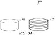
- FIG. 3Ais a diagram of an exemplary bladeless fan system with a housing and a stack of tubular elements
- FIG. 3Bis another diagram of an exemplary bladeless fan system with a housing and a singular layer of enclosed tubular elements
- FIG. 4is a diagram of an exemplary bladeless fan system incorporated into a scanner, implemented in accordance with embodiments of the invention
- FIG. 5is an exemplary tubular element with a nozzle structure
- FIG. 6is a diagram of an exemplary bladeless fan system incorporated into a scanner with a removable filter, implemented in accordance with embodiments of the invention.
- FIG. 7is a diagram of an exemplary bladeless fan system incorporated into a smart camera, implemented in accordance with embodiments of the invention.
- a bladeless dust removal systemin a first aspect, includes a source of air in a device that operates to generate air flow.
- Tubular elements in the deviceoperate to receive air from the source of air, operate to handle air, and operate to allow an expulsion of air through openings in the walls of the tubular elements.
- the tubular elementsconnect together through links.
- the openings in the walls of the tubular elementsare positioned so that the air flows through the openings in a substantially uniform direction in the device. The air flows such that the air is expelled from the device.
- a compact electro-optical device having a bladeless dust removal systemincludes a housing comprising the bladeless dust removal system and components of the electro-optical device.
- the bladeless dust removal systemincludes a source of air, preferably a motor compartment, and tubular elements in the device.
- the motor compartmentoperates to generate air flow.
- the tubular elementsoperate to receive air from the source of air, to handle air, and allow an expulsion of air through a lateral opening between the walls of the tubular elements.
- a portion of an interior wall of the tubular elementsoverhangs or overlaps a portion of an exterior wall of the same tubular elements.
- the tubular elementsconnect together through links.
- the openings between the walls of the tubular elementsare positioned so that air flows through towards an exhaust opening located embedded in the housing.
- the exhaust openingis located embedded in the housing to allow air to escape from an interior of the housing. Dust is expelled with the air through the exhaust opening.
- a scannerhas a dust removal system that includes a compartment and a scanner module.
- the compartmentincludes the bladeless dust removal system.
- the scanner moduleincludes components of a compact electro-optical device.
- the bladeless dust removal systemincludes a source of air to generate air flow.
- Tubular elementsreceive air from the source of air, handle air within itself, and allow an expulsion of air through a lateral opening between the walls of the tubular elements.
- a portion of an interior wall of the tubular elementsoverhangs a portion of an exterior wall of the tubular elements.
- Tubular elementsconnect together through links.
- the lateral opening between the walls of the tubular elementsare positioned so that air flows through towards an exhaust opening located embedded in the scanner module.
- the exhaust opening located embedded in the scannermule to allow air to pass from an interior of the compartment of the scanner module. Dust is expelled with the air through the exhaust opening.
- Embodiments of the inventiondisclose a bladeless dust removal system that functions in compact devices, such as laser scanner and other electro-optical devices.
- the bladeless dust removal systemincorporates tubular elements instead of a rotating fan. Air passes in and through the tubular elements causing air flow to move into a particular direction. In an exemplary embodiment, air flow occurs through the process of induction and entrainment.
- FIG. 1a bladeless fan manufactured by Dyson Ltd. of Malmesbury, United Kingdom is shown in a fan 100 .
- the design of fan 100is not suitable for usage in compact electro-optical devices due to size and generated air flow.
- Compact electro-optical devicestend to be small and can range from 5 centimeters to 15 centimeters in diameter, length, or height.
- laser scanning devices 200 A and 200 Bare shown and incorporate a bladeless dust removal system.
- the laser scanning devicesare compact and can be portable or handheld. Because of the compact size of the laser scanning devices, traditional fan systems are not suitable for implementation into the laser scanning devices. The compact nature of the laser scanning devices can still accommodate a bladeless fan system, which allows air to flow through the devices and be expelled through an exhaust opening.
- a bladeless fan systemwith a housing and tubular elements
- the tubular elementscan vary in size, shape, and configuration.
- the bladeless fan system 300 Aincorporates a stack of tubular elements 305 in a housing 310 .
- the tubular elements 305are positioned as parallel rings that are connected together with links.
- the stack of tubular elements 305can be sized and configured to fit within the compact structure of an electro-optical device.
- the bladeless fan system 300 Bincorporates a single layer of enclosed tubular elements 315 (or single layer of multiple tubular elements) of different sizes enclosed in a housing 320 .
- the tubular elements 315have members incorporating different diameters. Each member of the tubular elements 315 has a unique diameter.
- the enclosed tubular elements 315 (or multiple tubular elements)are connected together with links.
- FIGS. 3A and 3Billustrate the versatility in implementing embodiments of the invention.
- Tubular elementscan be shaped and configured in a variety of ways so long as the implementation allows air to flow from the tubular elements. The air flow direction can be developed so that the benefits of the bladeless fan system are achieved to remove dust particles.
- a bladeless fan systemis incorporated into a scanner 400 .
- the bladeless fan systemincludes a two-level tubular structure 404 .
- the tubular elements 404receive air flow from a motor compartment 406 through a pipe 405 .
- the airescapes from a lateral opening between an overhang or overlap of the interior and exterior walls of the tubular elements 404 .
- the tubular elements 404are connected to each other through links 403 .
- the links 403can be of a same or different material as the tubular elements 404 . Such material can be metal, plastic, or other suitable material for providing air flow.
- the dust from inside the scannerpasses from a housing 407 and is removed through slots 402 in a compartment 401 of the bladeless fan system. These slots 402 can be found on the periphery or top surface of the scanner 400 . These slots 402 also lead to the exterior of the scanner 400 .
- the scannercan incorporate a bladeless fan system that includes a single layer of enclosed tubular elements or a singular layer of multiple tubular elements of different sizes.
- Each circular tubular elementhas a different diameter than another circular tubular element.
- the tubular elementsare positioned in the same plane.
- scanner 400can incorporate tubular elements or pipes that supply clean air into the motor compartment from an outside air source or “Air Filtration Station”. This embodiment enables clean air to enter the system, further aiding the process of removing dust.
- motor compartment 406can be removed and replaced with an external air intake source. The air intake source could be connected directly to pipe 405 .
- the bladeless fan systemcan be incorporated into the walls of the housing of the scanner.
- the tubular elementscan be manufactured to be located inside the wall of the housing. In this way, there would be no additional elements inside the device.
- FIG. 5a nozzle structure 501 is shown of a tubular element 500 . More specifically, FIG. 5 is a cross-sectional view of the tubular element 500 . Rather than holes placed in the walls of the tubular elements, the tubular elements are designed so that there is an exit angle of a nozzle 502 along the entire pathway of the tubular elements based on the construction of the tubular element. As air is pushed into the tubular elements, air will escape where the two portions of the tubular element come closest together. In some embodiments, air escapes from an overhang or overlap of the interior and exterior walls of the tubular elements. Where the air escapes, air will flow in substantially the same direction. The exit angle of the air can be optimized to secure the most efficient air movement inside the scanner, taking into account the location, orientation, and size of internal components. In another embodiment, the air can escape at the nozzle 502 , which is at an end of the tubular element 500 .
- FIG. 6a bladeless fan system is incorporated into a scanner 600 .
- Scanner 600is similar to scanner 400 in FIG. 4 with the difference being that FIG. 6 includes a filter 608 to clean air before supplying it to the tubular elements 404 .
- Motor compartment 406can, alternatively or in addition, incorporate a removable filter, such as filter 608 . Outside particles can be removed by filter 608 or discarded.
- Bladeless fan system 600filters air that might be dirty.
- the bladeless fan systemcan attach to the smart camera, but it can also be detached when necessary.
- the bladeless dust removal systemcan be used in smart cameras for machine vision applications (e.g. object recognition), where the smart camera requires continuous dust removal from the lens cover.
- the air sourcemay be specified to come from a “clean, dry” air source or a factory wide air system. If the air source is generated by motor 406 attached to the bladeless dust fan removal system, filter 608 can be used to clean the air before the air is sent through the bladeless dust removal system to clean or remove dust particles in camera 700 , such as lens or lens cover.
- IPIngress Protection
- IP codeis a classification of the degrees of protection provided against the intrusion of solid objects and liquid objects. For example, consideration can be given to the ingress of air at pipes 405 and egress of air at slots 402 due to the holes needed for air intake and exhaust. Some systems must have a particular IP code. For example, the IP65/67 code indicates there should be no ingress of dust and there should be a complete protection against contact with dust. Also, water projected from jets against an enclosure from any direction shall have no harmful effects. And finally, ingress of water in harmful quantities shall not be possible when the enclosure is immersed in water under defined conditions of pressure and time.
- one possible way to solve the issue and have a devicecan be to have an external housing that includes the main housing of the device (i.e. the housing that has openings for air exhaust, as described in the Specification).
- an external housingthat includes the main housing of the device (i.e. the housing that has openings for air exhaust, as described in the Specification).
- Such external housingprovides high IP rating, as required in many applications, but would be removable, when needed, to allow air exhausting according to the described invention.
- electro-optical devicescan be electrostatic charging that can be caused by the air on a plastic window of the device.
- This electrostatic chargecan appear on a window that allows exit of light, laser light for example, for barcode reading or distance measuring, end entry of diffused light from the external ambient, object, barcodes surface. So, it could be necessary to use ionized air.
- the source of airsuch as a motor or motor compartment, generates ionized air.
Landscapes
- Physics & Mathematics (AREA)
- General Physics & Mathematics (AREA)
- Optics & Photonics (AREA)
- Structures Of Non-Positive Displacement Pumps (AREA)
- Camera Bodies And Camera Details Or Accessories (AREA)
Abstract
Description
Claims (20)
Priority Applications (1)
| Application Number | Priority Date | Filing Date | Title |
|---|---|---|---|
| US15/753,749US10712552B2 (en) | 2015-08-21 | 2016-08-22 | Bladeless dust removal system for compact devices |
Applications Claiming Priority (3)
| Application Number | Priority Date | Filing Date | Title |
|---|---|---|---|
| US201562208168P | 2015-08-21 | 2015-08-21 | |
| PCT/IB2016/055014WO2017033122A1 (en) | 2015-08-21 | 2016-08-22 | Bladeless dust removal system for compact devices |
| US15/753,749US10712552B2 (en) | 2015-08-21 | 2016-08-22 | Bladeless dust removal system for compact devices |
Publications (2)
| Publication Number | Publication Date |
|---|---|
| US20180284427A1 US20180284427A1 (en) | 2018-10-04 |
| US10712552B2true US10712552B2 (en) | 2020-07-14 |
Family
ID=57249838
Family Applications (1)
| Application Number | Title | Priority Date | Filing Date |
|---|---|---|---|
| US15/753,749ActiveUS10712552B2 (en) | 2015-08-21 | 2016-08-22 | Bladeless dust removal system for compact devices |
Country Status (3)
| Country | Link |
|---|---|
| US (1) | US10712552B2 (en) |
| EP (1) | EP3338134B1 (en) |
| WO (1) | WO2017033122A1 (en) |
Families Citing this family (2)
| Publication number | Priority date | Publication date | Assignee | Title |
|---|---|---|---|---|
| WO2017033122A1 (en) | 2015-08-21 | 2017-03-02 | Datalogic Ip Tech S.R.L. | Bladeless dust removal system for compact devices |
| EP3611493B1 (en) | 2018-08-13 | 2025-05-14 | Komax Holding Ag | Inspection apparatus for inspecting a cable tip of a cable and method for cleaning |
Citations (30)
| Publication number | Priority date | Publication date | Assignee | Title |
|---|---|---|---|---|
| US2488467A (en) | 1947-09-12 | 1949-11-15 | Lisio Salvatore De | Motor-driven fan |
| US4561732A (en)* | 1982-09-21 | 1985-12-31 | Man Maschinenfabrik Augsburg-Nurnberg Ag | Driving mirror for motor vehicles |
| US5424806A (en) | 1994-02-28 | 1995-06-13 | Xerox Corporation | Tubular frame with integral air duct for heat, dirt and ozone management |
| US5862037A (en)* | 1997-03-03 | 1999-01-19 | Inclose Design, Inc. | PC card for cooling a portable computer |
| JP2001108880A (en)* | 1999-10-01 | 2001-04-20 | Toshiba Corp | Air purge hood |
| US20040175202A1 (en) | 2003-03-03 | 2004-09-09 | Konica Min Olta Holdings, Inc. | Image forming apparatus having imagewise exposure device provided cooling device therewith, and producing method thereof |
| US20060068696A1 (en)* | 2004-09-16 | 2006-03-30 | Ashford James A | Apparatus and method for laser scanner cleaning and protection |
| US7374294B2 (en)* | 2005-11-03 | 2008-05-20 | Gerald Willey | Method and apparatus for improving image quality in a reflecting telescope |
| US20080205878A1 (en)* | 2007-01-30 | 2008-08-28 | Nikon Corporation | Digital camera |
| US20080285132A1 (en)* | 2007-05-18 | 2008-11-20 | O'kane Kevin James | Element deflector for lenses, and/or method of making the same |
| US20090060711A1 (en) | 2007-09-04 | 2009-03-05 | Dyson Technology Limited | Fan |
| US20100091083A1 (en)* | 2008-10-10 | 2010-04-15 | Yukio Itami | Optical scanning device and image forming apparatus |
| US20110023915A1 (en)* | 2009-07-28 | 2011-02-03 | Mcconnell Craig | Method and apparatus for preventing a build up of snow or dust |
| US7931449B2 (en) | 2008-09-23 | 2011-04-26 | Dyson Technology Limited | Fan |
| US7972111B2 (en) | 2009-03-04 | 2011-07-05 | Dyson Technology Limited | Fan assembly |
| US8052379B2 (en) | 2009-03-04 | 2011-11-08 | Dyson Technology Limited | Fan assembly |
| US20120118327A1 (en)* | 2010-11-16 | 2012-05-17 | Rouben Mazmanyan | Dust Removal System for Electronic Devices |
| JP2012168457A (en) | 2011-02-16 | 2012-09-06 | Nikon Corp | Blower for lens |
| US8714937B2 (en) | 2009-03-04 | 2014-05-06 | Dyson Technology Limited | Fan assembly |
| US8721307B2 (en) | 2010-05-27 | 2014-05-13 | Dyson Technology Limited | Device for blowing air by means of narrow slit nozzle assembly |
| US8721286B2 (en) | 2009-03-04 | 2014-05-13 | Dyson Technology Limited | Fan assembly |
| US8734121B2 (en) | 2011-06-16 | 2014-05-27 | Kable Enterprise Co., Ltd. | Flow guide structure for bladeless air fans |
| US8784049B2 (en) | 2009-03-04 | 2014-07-22 | Dyson Technology Limited | Fan |
| US8784071B2 (en) | 2009-03-04 | 2014-07-22 | Dyson Technology Limited | Fan assembly |
| US8882451B2 (en) | 2010-03-23 | 2014-11-11 | Dyson Technology Limited | Fan |
| US8950036B2 (en)* | 2009-12-11 | 2015-02-10 | Samsung Electronics Co., Ltd | Dust remover for charge-coupled device |
| CN204239348U (en) | 2014-11-11 | 2015-04-01 | 深圳市富源城科技有限公司 | A kind of pin is without blade fan |
| US20160001330A1 (en)* | 2011-03-10 | 2016-01-07 | Alan Romack | Integrated automotive system, nozzle assembly and remote control method for cleaning an image sensor's exterior or objective lens surface |
| US20160209645A1 (en)* | 2013-11-27 | 2016-07-21 | Halliburton Energy Services, Inc. | Air Curtain Generator for Optical Sensing Devices |
| WO2017033122A1 (en) | 2015-08-21 | 2017-03-02 | Datalogic Ip Tech S.R.L. | Bladeless dust removal system for compact devices |
- 2016
- 2016-08-22WOPCT/IB2016/055014patent/WO2017033122A1/ennot_activeCeased
- 2016-08-22EPEP16791671.7Apatent/EP3338134B1/enactiveActive
- 2016-08-22USUS15/753,749patent/US10712552B2/enactiveActive
Patent Citations (33)
| Publication number | Priority date | Publication date | Assignee | Title |
|---|---|---|---|---|
| US2488467A (en) | 1947-09-12 | 1949-11-15 | Lisio Salvatore De | Motor-driven fan |
| US4561732A (en)* | 1982-09-21 | 1985-12-31 | Man Maschinenfabrik Augsburg-Nurnberg Ag | Driving mirror for motor vehicles |
| US5424806A (en) | 1994-02-28 | 1995-06-13 | Xerox Corporation | Tubular frame with integral air duct for heat, dirt and ozone management |
| US5862037A (en)* | 1997-03-03 | 1999-01-19 | Inclose Design, Inc. | PC card for cooling a portable computer |
| JP2001108880A (en)* | 1999-10-01 | 2001-04-20 | Toshiba Corp | Air purge hood |
| US20040175202A1 (en) | 2003-03-03 | 2004-09-09 | Konica Min Olta Holdings, Inc. | Image forming apparatus having imagewise exposure device provided cooling device therewith, and producing method thereof |
| US20060068696A1 (en)* | 2004-09-16 | 2006-03-30 | Ashford James A | Apparatus and method for laser scanner cleaning and protection |
| US7374294B2 (en)* | 2005-11-03 | 2008-05-20 | Gerald Willey | Method and apparatus for improving image quality in a reflecting telescope |
| US20080205878A1 (en)* | 2007-01-30 | 2008-08-28 | Nikon Corporation | Digital camera |
| US20080285132A1 (en)* | 2007-05-18 | 2008-11-20 | O'kane Kevin James | Element deflector for lenses, and/or method of making the same |
| US20090060711A1 (en) | 2007-09-04 | 2009-03-05 | Dyson Technology Limited | Fan |
| US8764412B2 (en)* | 2007-09-04 | 2014-07-01 | Dyson Technology Limited | Fan |
| US7931449B2 (en) | 2008-09-23 | 2011-04-26 | Dyson Technology Limited | Fan |
| US20100091083A1 (en)* | 2008-10-10 | 2010-04-15 | Yukio Itami | Optical scanning device and image forming apparatus |
| US8784071B2 (en) | 2009-03-04 | 2014-07-22 | Dyson Technology Limited | Fan assembly |
| US7972111B2 (en) | 2009-03-04 | 2011-07-05 | Dyson Technology Limited | Fan assembly |
| US8052379B2 (en) | 2009-03-04 | 2011-11-08 | Dyson Technology Limited | Fan assembly |
| US8932028B2 (en) | 2009-03-04 | 2015-01-13 | Dyson Technology Limited | Fan assembly |
| US8714937B2 (en) | 2009-03-04 | 2014-05-06 | Dyson Technology Limited | Fan assembly |
| US8721286B2 (en) | 2009-03-04 | 2014-05-13 | Dyson Technology Limited | Fan assembly |
| US8784049B2 (en) | 2009-03-04 | 2014-07-22 | Dyson Technology Limited | Fan |
| US20110023915A1 (en)* | 2009-07-28 | 2011-02-03 | Mcconnell Craig | Method and apparatus for preventing a build up of snow or dust |
| US8950036B2 (en)* | 2009-12-11 | 2015-02-10 | Samsung Electronics Co., Ltd | Dust remover for charge-coupled device |
| US8882451B2 (en) | 2010-03-23 | 2014-11-11 | Dyson Technology Limited | Fan |
| US8721307B2 (en) | 2010-05-27 | 2014-05-13 | Dyson Technology Limited | Device for blowing air by means of narrow slit nozzle assembly |
| US9011116B2 (en) | 2010-05-27 | 2015-04-21 | Dyson Technology Limited | Device for blowing air by means of a nozzle assembly |
| US20120118327A1 (en)* | 2010-11-16 | 2012-05-17 | Rouben Mazmanyan | Dust Removal System for Electronic Devices |
| JP2012168457A (en) | 2011-02-16 | 2012-09-06 | Nikon Corp | Blower for lens |
| US20160001330A1 (en)* | 2011-03-10 | 2016-01-07 | Alan Romack | Integrated automotive system, nozzle assembly and remote control method for cleaning an image sensor's exterior or objective lens surface |
| US8734121B2 (en) | 2011-06-16 | 2014-05-27 | Kable Enterprise Co., Ltd. | Flow guide structure for bladeless air fans |
| US20160209645A1 (en)* | 2013-11-27 | 2016-07-21 | Halliburton Energy Services, Inc. | Air Curtain Generator for Optical Sensing Devices |
| CN204239348U (en) | 2014-11-11 | 2015-04-01 | 深圳市富源城科技有限公司 | A kind of pin is without blade fan |
| WO2017033122A1 (en) | 2015-08-21 | 2017-03-02 | Datalogic Ip Tech S.R.L. | Bladeless dust removal system for compact devices |
Non-Patent Citations (1)
| Title |
|---|
| Strickland, Jonathan et al., "How the Dyson Bladeless Fan Works", 7 pages. Accessed Aug. 10, 2016 at: http://electronics.howstuffworks.com/gadgets/home/dyson-bladeless-fan.htm/printable. |
Also Published As
| Publication number | Publication date |
|---|---|
| WO2017033122A1 (en) | 2017-03-02 |
| EP3338134B1 (en) | 2023-07-19 |
| US20180284427A1 (en) | 2018-10-04 |
| EP3338134A1 (en) | 2018-06-27 |
Similar Documents
| Publication | Publication Date | Title |
|---|---|---|
| US20250050263A1 (en) | Air cleaning apparatus with a moist filter | |
| US10712552B2 (en) | Bladeless dust removal system for compact devices | |
| US20070207721A1 (en) | Electronic device and filtering unit | |
| KR20120081814A (en) | Housing assembly and monitoring camera apparatus having the same | |
| US8444330B2 (en) | In-magazine imaging device enclosure | |
| US12246280B2 (en) | Air cleaning apparatus with a moist filter | |
| CN103676413A (en) | Dustproof mining camera | |
| CN111343364A (en) | Image extraction device and automatic cleaning assembly thereof | |
| JP5895263B2 (en) | Anti-stain device for observation window | |
| CN214952871U (en) | Laser instrument camera lens dustproof construction | |
| JP2009053065A (en) | Dust photographing device | |
| KR20110066323A (en) | Dust removing device of image pickup device | |
| CN107812422B (en) | Polishing dust removal system | |
| KR20190121037A (en) | Moving air cleaner | |
| CN116009467A (en) | A capture device and evaluation method for biological diversity | |
| CN116107136A (en) | A lens antifouling device and method for collecting dust particle images | |
| KR20170134281A (en) | A Filtering Apparatus for an Intake Air of a System of Air Management | |
| US20040057852A1 (en) | Suction diffuser | |
| JP2018100894A (en) | Harmful substance detection device | |
| TW201538061A (en) | Power supply unit | |
| CN204422865U (en) | A kind of camera lens module screw thread dust arrester | |
| RU219629U1 (en) | DEVICE FOR PROTECTION OF SUPERVISION CAMERA WITH COOLING | |
| KR20150083186A (en) | Compact scrubber which is apt to carry | |
| EP3641615B1 (en) | Wet/dry vacuum cleaner | |
| KR20200053977A (en) | Air cleaning apparatus |
Legal Events
| Date | Code | Title | Description |
|---|---|---|---|
| FEPP | Fee payment procedure | Free format text:ENTITY STATUS SET TO UNDISCOUNTED (ORIGINAL EVENT CODE: BIG.); ENTITY STATUS OF PATENT OWNER: LARGE ENTITY | |
| STPP | Information on status: patent application and granting procedure in general | Free format text:NON FINAL ACTION MAILED | |
| AS | Assignment | Owner name:DATALOGIC IP TECH S.R.L., ITALY Free format text:ASSIGNMENT OF ASSIGNORS INTEREST;ASSIGNOR:VOLTA, VALENTINA;REEL/FRAME:048715/0719 Effective date:20150916 | |
| STPP | Information on status: patent application and granting procedure in general | Free format text:RESPONSE TO NON-FINAL OFFICE ACTION ENTERED AND FORWARDED TO EXAMINER | |
| STPP | Information on status: patent application and granting procedure in general | Free format text:FINAL REJECTION MAILED | |
| STPP | Information on status: patent application and granting procedure in general | Free format text:NOTICE OF ALLOWANCE MAILED -- APPLICATION RECEIVED IN OFFICE OF PUBLICATIONS | |
| STPP | Information on status: patent application and granting procedure in general | Free format text:PUBLICATIONS -- ISSUE FEE PAYMENT VERIFIED | |
| STCF | Information on status: patent grant | Free format text:PATENTED CASE | |
| MAFP | Maintenance fee payment | Free format text:PAYMENT OF MAINTENANCE FEE, 4TH YEAR, LARGE ENTITY (ORIGINAL EVENT CODE: M1551); ENTITY STATUS OF PATENT OWNER: LARGE ENTITY Year of fee payment:4 |