US10709888B2 - Systems and methods for making and using an electrical stimulation system for peripheral nerve stimulation - Google Patents
Systems and methods for making and using an electrical stimulation system for peripheral nerve stimulationDownload PDFInfo
- Publication number
- US10709888B2 US10709888B2US15/656,734US201715656734AUS10709888B2US 10709888 B2US10709888 B2US 10709888B2US 201715656734 AUS201715656734 AUS 201715656734AUS 10709888 B2US10709888 B2US 10709888B2
- Authority
- US
- United States
- Prior art keywords
- lead
- electrical stimulation
- end portion
- lead body
- distal end
- Prior art date
- Legal status (The legal status is an assumption and is not a legal conclusion. Google has not performed a legal analysis and makes no representation as to the accuracy of the status listed.)
- Active, expires
Links
- 230000000638stimulationEffects0.000titleclaimsabstractdescription106
- 210000000578peripheral nerveAnatomy0.000titleabstractdescription21
- 238000000034methodMethods0.000titledescription12
- 230000007383nerve stimulationEffects0.000titledescription4
- 239000004020conductorSubstances0.000claimsabstractdescription10
- 230000008878couplingEffects0.000claimsabstractdescription9
- 238000010168coupling processMethods0.000claimsabstractdescription9
- 238000005859coupling reactionMethods0.000claimsabstractdescription9
- 230000003467diminishing effectEffects0.000claimsdescription3
- 238000013507mappingMethods0.000abstractdescription9
- 238000002513implantationMethods0.000abstractdescription5
- 230000000712assemblyEffects0.000description12
- 238000000429assemblyMethods0.000description12
- 210000001519tissueAnatomy0.000description10
- 210000005036nerveAnatomy0.000description6
- 210000000278spinal cordAnatomy0.000description4
- 239000000853adhesiveSubstances0.000description3
- 230000001070adhesive effectEffects0.000description3
- 239000000560biocompatible materialSubstances0.000description3
- 238000005266castingMethods0.000description3
- 238000003780insertionMethods0.000description3
- 230000037431insertionEffects0.000description3
- 229910052751metalInorganic materials0.000description3
- 239000002184metalSubstances0.000description3
- 238000000465mouldingMethods0.000description3
- 210000003205muscleAnatomy0.000description3
- 229920001296polysiloxanePolymers0.000description3
- -1polytetrafluoroethylenePolymers0.000description3
- 229920002635polyurethanePolymers0.000description3
- 239000004814polyurethaneSubstances0.000description3
- 239000007787solidSubstances0.000description3
- 206010021639IncontinenceDiseases0.000description2
- 208000002193PainDiseases0.000description2
- KDLHZDBZIXYQEI-UHFFFAOYSA-NPalladiumChemical compound[Pd]KDLHZDBZIXYQEI-UHFFFAOYSA-N0.000description2
- 239000004696Poly ether ether ketoneSubstances0.000description2
- 239000004642PolyimideSubstances0.000description2
- 210000001015abdomenAnatomy0.000description2
- 230000008901benefitEffects0.000description2
- 210000004556brainAnatomy0.000description2
- 210000004027cellAnatomy0.000description2
- 239000003814drugSubstances0.000description2
- 229940079593drugDrugs0.000description2
- 210000003414extremityAnatomy0.000description2
- 238000001746injection mouldingMethods0.000description2
- 230000014759maintenance of locationEffects0.000description2
- 230000005012migrationEffects0.000description2
- 238000013508migrationMethods0.000description2
- 239000012811non-conductive materialSubstances0.000description2
- 210000004197pelvisAnatomy0.000description2
- BASFCYQUMIYNBI-UHFFFAOYSA-NplatinumChemical compound[Pt]BASFCYQUMIYNBI-UHFFFAOYSA-N0.000description2
- 229920002530polyetherether ketonePolymers0.000description2
- 229920001721polyimidePolymers0.000description2
- 229920001343polytetrafluoroethylenePolymers0.000description2
- 239000004810polytetrafluoroethyleneSubstances0.000description2
- 230000008569processEffects0.000description2
- 230000001225therapeutic effectEffects0.000description2
- 238000011282treatmentMethods0.000description2
- OKTJSMMVPCPJKN-UHFFFAOYSA-NCarbonChemical compound[C]OKTJSMMVPCPJKN-UHFFFAOYSA-N0.000description1
- 229920001651CyanoacrylatePolymers0.000description1
- 239000004593EpoxySubstances0.000description1
- 102000009123FibrinHuman genes0.000description1
- 108010073385FibrinProteins0.000description1
- BWGVNKXGVNDBDI-UHFFFAOYSA-NFibrin monomerChemical compoundCNC(=O)CNC(=O)CNBWGVNKXGVNDBDI-UHFFFAOYSA-N0.000description1
- 206010019233HeadachesDiseases0.000description1
- MWCLLHOVUTZFKS-UHFFFAOYSA-NMethyl cyanoacrylateChemical compoundCOC(=O)C(=C)C#NMWCLLHOVUTZFKS-UHFFFAOYSA-N0.000description1
- 208000019695Migraine diseaseDiseases0.000description1
- 201000001880Sexual dysfunctionDiseases0.000description1
- FAPWRFPIFSIZLT-UHFFFAOYSA-MSodium chlorideChemical compound[Na+].[Cl-]FAPWRFPIFSIZLT-UHFFFAOYSA-M0.000description1
- RTAQQCXQSZGOHL-UHFFFAOYSA-NTitaniumChemical compound[Ti]RTAQQCXQSZGOHL-UHFFFAOYSA-N0.000description1
- 206010044565TremorDiseases0.000description1
- 230000004913activationEffects0.000description1
- 229910045601alloyInorganic materials0.000description1
- 239000000956alloySubstances0.000description1
- 210000003484anatomyAnatomy0.000description1
- 230000009286beneficial effectEffects0.000description1
- 230000005540biological transmissionEffects0.000description1
- 239000007767bonding agentSubstances0.000description1
- 239000003990capacitorSubstances0.000description1
- 229910052799carbonInorganic materials0.000description1
- 239000000969carrierSubstances0.000description1
- 230000001413cellular effectEffects0.000description1
- 208000022371chronic pain syndromeDiseases0.000description1
- 230000006835compressionEffects0.000description1
- 238000007906compressionMethods0.000description1
- 229920001940conductive polymerPolymers0.000description1
- 208000037765diseases and disordersDiseases0.000description1
- 208000037265diseases, disorders, signs and symptomsDiseases0.000description1
- 208000035475disorderDiseases0.000description1
- 229950003499fibrinDrugs0.000description1
- 239000012530fluidSubstances0.000description1
- 229920002313fluoropolymerPolymers0.000description1
- 239000004811fluoropolymerSubstances0.000description1
- 239000000446fuelSubstances0.000description1
- 210000003128headAnatomy0.000description1
- 231100000869headacheToxicity0.000description1
- 230000001939inductive effectEffects0.000description1
- 238000001802infusionMethods0.000description1
- 238000011835investigationMethods0.000description1
- 208000028867ischemiaDiseases0.000description1
- 210000003141lower extremityAnatomy0.000description1
- 239000000463materialSubstances0.000description1
- 150000002739metalsChemical class0.000description1
- 206010027599migraineDiseases0.000description1
- 230000004048modificationEffects0.000description1
- 238000012986modificationMethods0.000description1
- 210000001087myotubuleAnatomy0.000description1
- 210000003739neckAnatomy0.000description1
- 210000004126nerve fiberAnatomy0.000description1
- 230000001537neural effectEffects0.000description1
- 230000003204osmotic effectEffects0.000description1
- 229910052763palladiumInorganic materials0.000description1
- 230000000737periodic effectEffects0.000description1
- 230000002093peripheral effectEffects0.000description1
- 229910052697platinumInorganic materials0.000description1
- HWLDNSXPUQTBOD-UHFFFAOYSA-Nplatinum-iridium alloyChemical compound[Ir].[Pt]HWLDNSXPUQTBOD-UHFFFAOYSA-N0.000description1
- 230000001681protective effectEffects0.000description1
- 230000004044responseEffects0.000description1
- 231100000872sexual dysfunctionToxicity0.000description1
- 239000011780sodium chlorideSubstances0.000description1
- 238000012360testing methodMethods0.000description1
- 238000002560therapeutic procedureMethods0.000description1
- 229910052719titaniumInorganic materials0.000description1
- 239000010936titaniumSubstances0.000description1
- 210000003901trigeminal nerveAnatomy0.000description1
- 210000001364upper extremityAnatomy0.000description1
Images


Classifications
- A—HUMAN NECESSITIES
- A61—MEDICAL OR VETERINARY SCIENCE; HYGIENE
- A61N—ELECTROTHERAPY; MAGNETOTHERAPY; RADIATION THERAPY; ULTRASOUND THERAPY
- A61N1/00—Electrotherapy; Circuits therefor
- A61N1/02—Details
- A61N1/04—Electrodes
- A61N1/05—Electrodes for implantation or insertion into the body, e.g. heart electrode
- A61N1/0551—Spinal or peripheral nerve electrodes
- A—HUMAN NECESSITIES
- A61—MEDICAL OR VETERINARY SCIENCE; HYGIENE
- A61B—DIAGNOSIS; SURGERY; IDENTIFICATION
- A61B17/00—Surgical instruments, devices or methods
- A61B17/34—Trocars; Puncturing needles
- A61B17/3468—Trocars; Puncturing needles for implanting or removing devices, e.g. prostheses, implants, seeds, wires
- A—HUMAN NECESSITIES
- A61—MEDICAL OR VETERINARY SCIENCE; HYGIENE
- A61N—ELECTROTHERAPY; MAGNETOTHERAPY; RADIATION THERAPY; ULTRASOUND THERAPY
- A61N1/00—Electrotherapy; Circuits therefor
- A61N1/18—Applying electric currents by contact electrodes
- A61N1/32—Applying electric currents by contact electrodes alternating or intermittent currents
- A61N1/36—Applying electric currents by contact electrodes alternating or intermittent currents for stimulation
- A61N1/3605—Implantable neurostimulators for stimulating central or peripheral nerve system
- A61N1/3606—Implantable neurostimulators for stimulating central or peripheral nerve system adapted for a particular treatment
- A61N1/36071—Pain
- A—HUMAN NECESSITIES
- A61—MEDICAL OR VETERINARY SCIENCE; HYGIENE
- A61N—ELECTROTHERAPY; MAGNETOTHERAPY; RADIATION THERAPY; ULTRASOUND THERAPY
- A61N1/00—Electrotherapy; Circuits therefor
- A61N1/18—Applying electric currents by contact electrodes
- A61N1/32—Applying electric currents by contact electrodes alternating or intermittent currents
- A61N1/36—Applying electric currents by contact electrodes alternating or intermittent currents for stimulation
- A61N1/3605—Implantable neurostimulators for stimulating central or peripheral nerve system
- A61N1/36128—Control systems
- A61N1/36146—Control systems specified by the stimulation parameters
- A61N1/36182—Direction of the electrical field, e.g. with sleeve around stimulating electrode
- A61N1/36185—Selection of the electrode configuration
- A—HUMAN NECESSITIES
- A61—MEDICAL OR VETERINARY SCIENCE; HYGIENE
- A61N—ELECTROTHERAPY; MAGNETOTHERAPY; RADIATION THERAPY; ULTRASOUND THERAPY
- A61N1/00—Electrotherapy; Circuits therefor
- A61N1/18—Applying electric currents by contact electrodes
- A61N1/32—Applying electric currents by contact electrodes alternating or intermittent currents
- A61N1/36—Applying electric currents by contact electrodes alternating or intermittent currents for stimulation
- A61N1/372—Arrangements in connection with the implantation of stimulators
- A61N1/37211—Means for communicating with stimulators
- A61N1/37217—Means for communicating with stimulators characterised by the communication link, e.g. acoustic or tactile
- A61N1/37223—Circuits for electromagnetic coupling
- A61N1/37229—Shape or location of the implanted or external antenna
- A—HUMAN NECESSITIES
- A61—MEDICAL OR VETERINARY SCIENCE; HYGIENE
- A61N—ELECTROTHERAPY; MAGNETOTHERAPY; RADIATION THERAPY; ULTRASOUND THERAPY
- A61N1/00—Electrotherapy; Circuits therefor
- A61N1/18—Applying electric currents by contact electrodes
- A61N1/32—Applying electric currents by contact electrodes alternating or intermittent currents
- A61N1/36—Applying electric currents by contact electrodes alternating or intermittent currents for stimulation
- A61N1/372—Arrangements in connection with the implantation of stimulators
- A61N1/37211—Means for communicating with stimulators
- A61N1/37235—Aspects of the external programmer
- A—HUMAN NECESSITIES
- A61—MEDICAL OR VETERINARY SCIENCE; HYGIENE
- A61N—ELECTROTHERAPY; MAGNETOTHERAPY; RADIATION THERAPY; ULTRASOUND THERAPY
- A61N1/00—Electrotherapy; Circuits therefor
- A61N1/18—Applying electric currents by contact electrodes
- A61N1/32—Applying electric currents by contact electrodes alternating or intermittent currents
- A61N1/36—Applying electric currents by contact electrodes alternating or intermittent currents for stimulation
- A61N1/372—Arrangements in connection with the implantation of stimulators
- A61N1/378—Electrical supply
- A61N1/3787—Electrical supply from an external energy source
- A—HUMAN NECESSITIES
- A61—MEDICAL OR VETERINARY SCIENCE; HYGIENE
- A61N—ELECTROTHERAPY; MAGNETOTHERAPY; RADIATION THERAPY; ULTRASOUND THERAPY
- A61N1/00—Electrotherapy; Circuits therefor
- A61N1/18—Applying electric currents by contact electrodes
- A61N1/32—Applying electric currents by contact electrodes alternating or intermittent currents
- A61N1/36—Applying electric currents by contact electrodes alternating or intermittent currents for stimulation
- A61N1/36007—Applying electric currents by contact electrodes alternating or intermittent currents for stimulation of urogenital or gastrointestinal organs, e.g. for incontinence control
- A—HUMAN NECESSITIES
- A61—MEDICAL OR VETERINARY SCIENCE; HYGIENE
- A61N—ELECTROTHERAPY; MAGNETOTHERAPY; RADIATION THERAPY; ULTRASOUND THERAPY
- A61N1/00—Electrotherapy; Circuits therefor
- A61N1/18—Applying electric currents by contact electrodes
- A61N1/32—Applying electric currents by contact electrodes alternating or intermittent currents
- A61N1/36—Applying electric currents by contact electrodes alternating or intermittent currents for stimulation
- A61N1/3605—Implantable neurostimulators for stimulating central or peripheral nerve system
- A61N1/3606—Implantable neurostimulators for stimulating central or peripheral nerve system adapted for a particular treatment
- A61N1/36062—Spinal stimulation
- A—HUMAN NECESSITIES
- A61—MEDICAL OR VETERINARY SCIENCE; HYGIENE
- A61N—ELECTROTHERAPY; MAGNETOTHERAPY; RADIATION THERAPY; ULTRASOUND THERAPY
- A61N1/00—Electrotherapy; Circuits therefor
- A61N1/18—Applying electric currents by contact electrodes
- A61N1/32—Applying electric currents by contact electrodes alternating or intermittent currents
- A61N1/36—Applying electric currents by contact electrodes alternating or intermittent currents for stimulation
- A61N1/3605—Implantable neurostimulators for stimulating central or peripheral nerve system
- A61N1/3606—Implantable neurostimulators for stimulating central or peripheral nerve system adapted for a particular treatment
- A61N1/36107—Sexual dysfunction
- A—HUMAN NECESSITIES
- A61—MEDICAL OR VETERINARY SCIENCE; HYGIENE
- A61N—ELECTROTHERAPY; MAGNETOTHERAPY; RADIATION THERAPY; ULTRASOUND THERAPY
- A61N1/00—Electrotherapy; Circuits therefor
- A61N1/18—Applying electric currents by contact electrodes
- A61N1/32—Applying electric currents by contact electrodes alternating or intermittent currents
- A61N1/36—Applying electric currents by contact electrodes alternating or intermittent currents for stimulation
- A61N1/372—Arrangements in connection with the implantation of stimulators
Definitions
- the present inventionis directed to the area of implantable electrical stimulation systems and methods of making and using the systems.
- the present inventionis also directed to electrical stimulation systems for stimulation of peripheral nerves, as well as methods of making and using the electrical stimulation systems.
- Implantable electrical stimulation systemshave proven therapeutic in a variety of diseases and disorders.
- spinal cord stimulation systemshave been used as a therapeutic modality for the treatment of chronic pain syndromes.
- Sacral nerve stimulationhas been used to treat incontinence, as well as a number of other applications under investigation.
- Peripheral nerve stimulationcan be used to treat a variety of disorders in the extremities, face, neck, head, abdomen, pelvis, trunk, and other portions of the body including, but not limited to, pain, incontinence, sexual dysfunction, headache, migraine, tremor, and the like.
- a stimulatorcan include a control module (with a pulse generator), one or more leads, and an array of stimulator electrodes on each lead.
- the stimulator electrodesare in contact with or near the nerves, muscles, or other tissue to be stimulated.
- the pulse generator in the control modulegenerates electrical pulses that are delivered by the electrodes to body tissue.
- One embodimentis an electrical stimulation lead that includes a lead body having a proximal end portion and a distal end; a terminal disposed along the proximal end portion of the lead body; a single electrode disposed at the distal end of the lead body; a conductor extending along the lead body and electrically coupling the terminal to the single electrode; and an adjustable sheath disposed over a portion of the lead body to cover a selected portion of the single electrode by displacing the sheath forwards or backwards relative to the single electrode to control a size of a portion of the electrode exposed for stimulation of tissue.
- the electrical stimulation leadfurther includes adhesive for application to the sheath and lead body or single electrode to fix the sheath to the lead body or single electrode after covering the selected portion of the single electrode.
- the electrical stimulation leadhas a diameter in a range of 0.020 inch to 0.040 inch.
- the single electrodeis configured and arranged to be cut by a user.
- the single electrodeis a solid cylinder of metal.
- the sheathis made of silicone, polyurethane, polyether ether ketone, polytetrafluoroethylene, polyimide, or a combination thereof.
- an electrical stimulation leadthat includes a lead body having a proximal end portion and a distal end portion, where the distal end portion has a smaller lateral width in at least one direction than a remainder of the lead body; at least one terminal disposed along the proximal end portion of the lead body; at least one electrode disposed at the distal end of the lead body; and at least one conductor extending along the lead body and electrically coupling the at least one terminal to the at least one electrode.
- the distal end portionhas a circular cross-section. In at least some embodiments, the distal end portion of the electrical stimulation lead has a diameter of 0.020 inch or less. In at least some embodiments, the remainder of the electrical stimulation lead has a diameter of at least 0.040 inch.
- the distal end portionhas a cross-section with a major axis width and a minor axis width of different values.
- the minor axis width of the distal end portion of the electrical stimulation leadhas a value of 0.020 inch or less.
- the at least one electrodeis a plurality of electrodes. In at least some embodiments, at least one of the at least one electrode does not extend around a full perimeter of the distal end portion of the electrical stimulation lead.
- kits for implanting a lead for stimulation of a peripheral nerve of a patientincludes a guidewire with an electrode disposed at a distal end of the guidewire; an introducer having a lumen for receiving the guidewire; and a lead including a lead body and at least one electrode disposed along a distal portion of the lead body, the lead body defining a lumen for receiving the guidewire.
- a further embodimentis a method for implanting a lead for stimulation of a peripheral nerve of a patient using the kit described above.
- the methodincludes advancing a distal portion of the guidewire using the introducer to a position adjacent the peripheral nerve; mapping a region around the peripheral nerve using the electrode of the guidewire; optionally removing the introducer; and advancing the lead over the guidewire, with a portion of the guidewire disposed in the lumen of the lead, to position the at least one electrode of the lead adjacent the peripheral nerve.
- mapping the region around the peripheral nerveincludes stimulation patient tissue using the electrode of the guidewire. In at least some embodiments, mapping the region around the peripheral nerve includes receiving electrical signals from patient tissue using the electrode of the guidewire. In at least some embodiments, the introducer is no more than 20 gauge. In at least some embodiments, the method further includes repositioning the distal portion of the guidewire to another site relative to the peripheral nerve.
- FIG. 1Ais a schematic view of one embodiment of an electrical stimulation system that includes a percutaneous lead body coupled to a control module, according to the invention
- FIG. 1Bis a schematic view of another embodiment of an electrical stimulation system that includes a percutaneous lead body with a single electrode coupled to a control module, according to the invention
- FIG. 2Ais a schematic view of one embodiment of a plurality of connector assemblies disposed in the control module of FIG. 1 a , the connector assemblies configured and arranged to receive the proximal portions of the lead bodies of FIG. 1 a , according to the invention;
- FIG. 2Bis a schematic view of one embodiment of a proximal portion of the lead body of FIG. 1A , a lead extension, and the control module of FIG. 1A , the lead extension configured and arranged to couple the lead body to the control module, according to the invention;
- FIG. 3Ais a schematic side view of a distal end of one embodiment of a lead having a sheath for covering a portion of an electrode, according to the invention
- FIG. 3Bis a schematic side view of the lead of FIG. 3A with the sheath pulled backward, according to the invention
- FIG. 3Cis a schematic side view of the lead of FIG. 3A with the sheath pulled forward, according to the invention.
- FIG. 3Dis a schematic side view of the lead of FIG. 3A with a portion of the electrode cut to reduce a length of the electrode, according to the invention
- FIG. 4Ais a schematic side view of a portion of one embodiment of a lead having a low-profile distal portion, according to the invention.
- FIG. 4Bis a lateral cross-section of a wider portion of the lead of FIG. 4A , according to the invention.
- FIG. 4Cis a lateral cross-section of one embodiment of the low-profile distal portion of the lead of FIG. 4A , according to the invention.
- FIG. 4Dis a lateral cross-section of another embodiment of the low-profile distal portion of the lead of FIG. 4A , according to the invention.
- FIG. 4Eis a lateral cross-section of the embodiment of the low-profile distal portion of the lead of FIG. 4D with segmented electrodes, according to the invention.
- FIG. 5is a schematic side view of one embodiment of components for a system, kit, or method for implanting a lead for stimulation of a peripheral nerve of a patient including an introducer, a guidewire, and a lead, according to the invention.
- FIG. 6is a schematic overview of one embodiment of components of an electrical stimulation system, according to the invention.
- the present inventionis directed to the area of implantable electrical stimulation systems and methods of making and using the systems.
- the present inventionis also directed to electrical stimulation systems for stimulation of peripheral nerves, as well as methods of making and using the electrical stimulation systems.
- Suitable implantable electrical stimulation systemsinclude, but are not limited to, an electrode lead (“lead”) with one or more electrodes disposed on a distal end of the lead and one or more terminals disposed on one or more proximal ends of the lead.
- Leadsinclude, for example, deep brain stimulation leads, percutaneous leads, paddle leads, and cuff leads. Examples of electrical stimulation systems with leads are found in, for example, U.S. Pat. Nos.
- 2007/01500362009/0187222; 2009/0276021; 2010/0076535; 2010/0268298; 2011/0005069; 2011/0004267; 2011/0078900; 2011/0130817; 2011/0130818; 2011/0238129; 2011/0313500; 2012/0016378; 2012/0046710; 2012/0071949; 2012/0165911; 2012/0197375; 2012/0203316; 2012/0203320; 2012/0203321; 2012/0316615; 2013/0105071; and 2013/0197602, all of which are incorporated by reference.
- FIG. 1Aillustrates schematically one embodiment of an electrical stimulation system 100 .
- the electrical stimulation system 100includes a control module (e.g., a stimulator or pulse generator) 102 and a percutaneous lead 103 .
- the lead 103includes a plurality of electrodes 134 that form an array of electrodes 133 .
- the control module 102typically includes an electronic subassembly 110 and an optional power source 120 disposed in a sealed housing 114 .
- the control module 102can be a microstimulator.
- the lead 103includes a lead body 106 coupling the control module 102 to the plurality of electrodes 134 .
- the lead body 106is isodiametric.
- FIG. 1Billustrates another embodiment of an electrical stimulation system 100 except that the lead 103 includes a single electrode 134 .
- the control module 102typically includes one or more connector assemblies 144 into which the proximal end of the lead body 106 can be plugged to make an electrical connection via connector contacts (e.g., 216 in FIG. 2A ) disposed in the connector assembly 144 and terminals (e.g., 210 in FIG. 2A ) disposed along the lead body 106 .
- the connector contactsare coupled to the electronic subassembly 110 and the terminals are coupled to the electrodes 134 .
- the control module 102may include a plurality of connector assemblies 144 .
- the leadmay be permanently connected to the control module.
- the one or more connector assemblies 144may be disposed in a header 150 .
- the header 150provides a protective covering over the one or more connector assemblies 144 .
- the header 150may be formed using any suitable process including, for example, casting, molding (including injection molding), and the like.
- one or more lead extensions 224can be disposed between the lead body 106 and the control module 102 to extend the distance between the lead body 106 and the control module 102 .
- the electrical stimulation system or components of the electrical stimulation systemare typically implanted into the body of a patient.
- the electrical stimulation systemcan be used for a variety of applications including, but not limited to, spinal cord stimulation, brain stimulation, neural stimulation, muscle activation via stimulation of nerves innervating muscle, and the like.
- the electrodes 134can be formed using any conductive, biocompatible material. Examples of suitable materials include metals, alloys, conductive polymers, conductive carbon, and the like, as well as combinations thereof. In at least some embodiments, one or more of the electrodes 134 are formed from one or more of: platinum, platinum iridium, palladium, or titanium.
- the number of electrodes 134 in the array of electrodes 133may vary. For example, there can be two, three, four, five, six, seven, eight, nine, ten, eleven, twelve, thirteen, fourteen, fifteen, sixteen, or more electrodes 134 . As will be recognized, other numbers of electrodes 134 may also be used.
- FIG. 1Aeight electrodes 134 are shown.
- FIG. 1Ba single electrode 134 is shown.
- the electrodes 134can be formed in any suitable shape including, for example, round, oval, triangular, rectangular, pentagonal, hexagonal, heptagonal, octagonal, or the like.
- the electrodesare ring electrodes.
- the electrodeis a tip electrode. It will be understood that other electrodes can also be used including sets of segmented electrodes that are arranged around the circumference of the lead and facilitate directional stimulation.
- the electrodes of the lead body 106are typically disposed in, or separated by, a non-conductive, biocompatible material including, for example, silicone, polyurethane, and the like or combinations thereof.
- the lead body 106may be formed in the desired shape by any process including, for example, extruding, molding (including injection molding), casting, and the like. Electrodes and connecting wires can be disposed onto or within a lead body either prior to or subsequent to a molding or casting process.
- the non-conductive materialtypically extends from the distal end of the lead body 106 to the proximal end of the lead body 106 .
- Terminalsare typically disposed at the proximal end of the lead body 106 for connection to corresponding conductive contacts (e.g., 216 in FIG. 2A ) in one or more connector assemblies (e.g., 144 in FIG. 1A ) disposed on, for example, the control module 102 (or to other devices, such as conductive contacts on a lead extension, an operating room cable, a splitter, an adaptor, or the like).
- Conductive wiresextend from the plurality of terminals (see e.g., 210 in FIG. 2A ) to the plurality of electrodes 133 .
- each of the plurality of terminalsis electrically coupled to at least one of the plurality of electrodes 133 .
- each of the plurality of terminalsis coupled to a single electrode 134 of the plurality of electrodes 133 .
- the conductive wiresmay be embedded in the non-conductive material of the lead or can be disposed in one or more lumens (not shown) extending along the lead. In some embodiments, there is an individual lumen for each conductive wire. In other embodiments, two or more conductive wires may extend through a lumen. There may also be one or more lumens (not shown) that open at, or near, the proximal end of the lead, for example, for inserting a stylet rod to facilitate placement of the lead within a body of a patient. Additionally, there may also be one or more lumens (not shown) that open at, or near, the distal end of the lead, for example, for infusion of drugs or medication into the site of implantation of the lead 103 . The one or more lumens may, optionally, be flushed continually, or on a regular basis, with saline, or the like. The one or more lumens can be permanently or removably sealable at the distal end.
- the lead body 106may be coupled to the one or more connector assemblies 144 disposed on the control module 102 .
- the control module 102can include any suitable number of connector assemblies 144 including, for example, one, two, three, four, five, six, seven, eight, or more connector assemblies 144 . It will be understood that other numbers of connector assemblies 144 may be used instead.
- the lead body 106includes eight terminals that are shown coupled with eight conductive contacts disposed in the connector assembly 144 .
- FIG. 2Ais a schematic side view of one embodiment of a connector assembly 144 disposed on the control module 102 .
- the proximal end 206 of the lead body 106is shown configured and arranged for insertion to the control module 102 .
- the connector assembly 144is disposed in the header 150 .
- the header 150defines a port 204 into which the proximal end 206 of the lead body 106 with terminals 210 can be inserted, as shown by directional arrows 212 , in order to gain access to the connector contacts disposed in the connector assembly 144 .
- the connector assembly 144includes a connector housing 214 and a plurality of connector contacts 216 disposed therein.
- the connector housing 214defines a port (not shown) that provides access to the plurality of connector contacts 216 .
- the connector assembly 144further includes a retaining element 218 configured and arranged to fasten the corresponding a lead retention sleeve or lead body 106 to the connector assembly 144 when the lead body 106 is inserted into the connector assembly 144 to prevent undesired detachment of the lead body 106 from the connector assembly 144 .
- the retaining element 218may include an aperture 220 through which a fastener (e.g., a set screw, pin, or the like) may be inserted and secured against a lead retention sleeve on the inserted lead body 106 .
- a fastenere.g., a set screw, pin, or the like
- the connector contacts 216can be aligned with the terminals 210 disposed on the lead body 106 to electrically couple the control module 102 to the electrodes ( 134 of FIG. 1A ) disposed at a distal end of the lead body 106 .
- Examples of connector assemblies in control modulesare found in, for example, U.S. Pat. No. 7,244,150 and U.S. Patent Application Publication No. 2008/0071320, which are incorporated by reference.
- the electrical stimulation systemincludes one or more lead extensions.
- the lead body 106can be coupled to one or more lead extensions which, in turn, are coupled to the control module 102 .
- a lead extension connector assembly 222is disposed on a lead extension 224 .
- the lead extension connector assembly 222is shown disposed at a distal end 226 of the lead extension 224 .
- the lead extension connector assembly 222includes a contact housing 228 .
- the contact housing 228defines at least one port 230 into which a proximal end 206 of the lead body 106 with terminals 210 can be inserted, as shown by directional arrow 238 .
- the lead extension connector assembly 222also includes a plurality of connector contacts 240 .
- the connector contacts 240 disposed in the contact housing 228can be aligned with the terminals 210 on the lead body 106 to electrically couple the lead extension 224 to the electrodes ( 134 of FIG. 1A ) disposed at a distal end (not shown) of the lead body 106 .
- the proximal end of a lead extensioncan be similarly configured and arranged as a proximal end of a lead body.
- the lead extension 224may include a plurality of conductive wires (not shown) that electrically couple the connector contacts 240 to terminal on a proximal end 248 of the lead extension 224 .
- the conductive wires disposed in the lead extension 224can be electrically coupled to a plurality of terminals (not shown) disposed on the proximal end 248 of the lead extension 224 .
- the proximal end 248 of the lead extension 224is configured and arranged for insertion into a lead extension connector assembly disposed in another lead extension.
- the proximal end 248 of the lead extension 224is configured and arranged for insertion into the connector assembly 144 disposed on the control module 102 .
- a peripheral nerve targetmay be in, for example, the upper extremities, the lower extremities, the head, the neck, the face, the abdomen, the pelvis, or the trunk.
- the peripheral target depthcan vary depending on the specific nerve target (for example, the face versus a limb) and the patient's individual anatomy (for example, depending on weight, height, age, gender, or the like).
- the volume of stimulation(as determined by, for example, the electrode array coverage and span and the stimulation parameters) can vary depending on, for example, the nerve target or the individual patient's pain etiology.
- FIG. 3Aillustrates one embodiment of a distal end of a lead 303 with a single electrode 334 and a non-conductive sheath 350 that can be used to cover a portion of the electrode to provide a customizable electrode length. Such an arrangement also results in a customizable stimulation volume so that a clinician can select the size of the stimulation region by moving the sheath 350 to a desired position along the distal end of the lead 303 .
- FIG. 3Billustrates an arrangement where the sheath 350 has been pulled back relative to the position illustrated in FIG. 3A to expose more of the electrode 334 for an effectively longer electrode and larger stimulation volume.
- FIG. 3Cillustrates an arrangement where the sheath 350 has been pushed forward relative to the position illustrated in FIG.
- the sheathcan be made out of any suitable, biocompatible material including, but not limited to, silicone, polyurethane, polyether ether ketone, polytetrafluoroethylene (e.g., TeflonTM) or other biocompatible fluoropolymers, polyimide or the like or any combination thereof.
- suitable, biocompatible materialincluding, but not limited to, silicone, polyurethane, polyether ether ketone, polytetrafluoroethylene (e.g., TeflonTM) or other biocompatible fluoropolymers, polyimide or the like or any combination thereof.
- the sheath 350is constructed so that a clinician or surgeon can move the sheath forward or backward from an initial position prior to implantation.
- the sheath 350can be adhered to the lead body or electrode 334 with medical adhesive or any other suitable, biocompatible bonding agent including, but not limited to, epoxy, fibrin, cyanoacrylate, any type of biocompatible medical adhesive, or the like.
- the leadhas a diameter in the range of 0.020 inch-0.040 inch (0.051 to 0.10 cm). In at least some embodiments, the lead has a diameter of no more than 0.020 inch (0.051 cm).
- the leadis constructed so that the electrode 334 can be cut to a desired length, as illustrated in FIG. 3D .
- the electrodecan be cut using a scalpel, shears, scissors, or any other suitable instrument.
- the electrodecan be cut to length, starting long and shortened if required as shown in FIG. 3D .
- the conductor attached to the leadshould be attached to a proximal portion of the lead so that the conductor/electrode is not severed when the electrode is cut.
- the electrode 334may be solid (for example, a solid cylinder of metal) so that, when cut, the lead is not open to inflow of fluid through the distal end of the lead.
- the leaddoes not include a sheath, but does include an electrode that can be cut.
- peripheral nerve targetsare not deep within the tissue including, but not limited to, locations in the head such as the occipital nerve, the orbital nerve, or the trigeminal nerve.
- a low profile lead body and electrode arraymay be preferred for these targets.
- a low profile lead configurationmay also be highly beneficial for other stimulation targets that are only a few millimeters below the surface of the skin.
- a low profile lead body with a diameter less than traditional SCS lead bodiesis desirable.
- the distal end of the lead, where the electrode or electrode array residescan be low profile and, in some instances, non-circular in cross-section.
- a low profile portion of a leadmay have a diameter in the range of 0.020 inch-0.040 inch (0.051 to 0.10 cm) or in some cases less than 0.020 inch (0.51 cm).
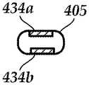
- FIG. 4Aillustrates one embodiment of a lead 403 with a distal portion 405 that has a smaller cross-section than a remainder 407 of the lead.
- the distal portion 405includes one or more electrodes 434 .
- FIG. 4Billustrates, in cross-section, the larger diameter 460 of the remainder 407 of the lead.
- FIGS. 4C and 4Dillustrate, in cross-section, two embodiments of the low-profile distal portion 405 .
- the cross-section of the low-profile distal portion 405is circular with a smaller diameter 462 than the remainder of the lead.
- the cross-section of the low-profile distal portion 405 of the leadis square or rectangular (with or without rounded corners) or oval.
- the low-profile distal portion 405has a minor axis 464 and a major axis 466 . At least the width of the minor axis 464 is smaller than the diameter 460 of the remainder 407 of the lead. The width of the major axis 466 may be equal to, or smaller than, the diameter 460 of the remainder of the lead.
- the low-profile distal portion 405 of the leadhas a diameter 462 , width of the minor axis 464 , or width of the major axis 466 in the range of 0.020 inch-0.040 inch (0.051 to 0.10 cm). In at least some embodiments, the low-profile distal portion 405 of the lead has a diameter 462 or width of the minor axis 464 of no more than 0.020 inch (0.051 cm). In at least some embodiments, the width of the remainder 407 of the lead is at least 0.040 inch (0.10 cm).
- the electrodes 434fully surround the perimeter of the distal portion 405 of the lead, as illustrated in FIG. 4A . In other embodiments, the electrodes 434 only partially surround (for example, no more than 75%, 50%, 34%, 25%, or less of) the perimeter of the lead body. In yet other embodiments, multiple segmented electrodes 434 can be disposed around the perimeter of the distal portion 405 of the lead similar to the segmented electrodes disclosed in U.S. Patent Applications Publication Nos.
- segmented electrodescan be used to provide directionality to the stimulation.
- segmented electrodescan be positioned on opposite sides of the distal portion 405 of the lead 403 , as illustrated in FIG. 4E .
- the sloping or diminishing region 409 between the distal portion 405 and the remainder 407 of the leadmay reduce migration of the lead.
- the small, highly flexible lead bodyalso helps to reduce or prevent migration as the mass of the lead body is lower and hence the momentum generated is smaller than a larger spinal cord stimulation lead.
- the smaller diameter or lower profile of the leadmay also reduce ischemia due to the lead and arising from vessel compression.
- FIG. 5illustrates another embodiment of a lead and related items for implanting the lead.
- a thin guidewire 570 with an electrode 572can first be inserted to access the potential target prior to placement of a lead 503 .
- the guidewire 570can be implanted through an introducer 574 , such as a small gauge needle.
- the guidewire 570 and mapping electrode 572may be used to determine the length, width, depth, or volume (or any combination thereof) of the target stimulation area which may help inform the electrode length (for example, for a lead such lead 303 in FIGS. 3A-3D ) or size of the electrode array of the lead.
- the guidewire 570includes an electrode 572 disposed on, or near, a distal end of guidewire.
- a conductor(not shown) will extend along the guidewire 570 from the electrode 572 to a proximal end of the guidewire so that the guidewire can be coupled to a device for providing or receiving electrical signals from the electrode 572 .
- the guidewire 570includes two or more electrodes which may be electrically coupled together or may be independent of each other with separate conductors extending along the guidewire.
- Each of the electrodescan be a ring electrode, tip electrode, a segmented electrode, or any other suitable type of electrode.
- a lead with multiple electrodescan include a tip electrode, ring electrodes, or segmented electrodes or any combination thereof.
- the introducer 574defines a lumen 576 through which the guidewire 570 can be delivered.
- the introducer 574is 20 gauge (0.036′′ or 0.091 cm nominal outer diameter) or smaller. Advancing a small mapping guidewire 470 adjacent the peripheral nerve and moving the small mapping guidewire with respect to the peripheral nerve may be easier and less time consuming than using a lead for mapping. Furthermore, this guidewire can be steerable to allow for repositioning of the guidewire, as needed. Repositioning of the introducer 574 or guidewire 570 is easier and faster with a smaller introducer instead of the conventional larger lead and its introducer.
- the guidewire 570 and its associated electrode 572can be used to map or otherwise test the response of the patient tissue to electrical stimulation. Additionally or alternatively, the guidewire 570 and its associated electrode 572 can be used to map the electrical signals from patient tissue. In particular, the electrode 570 of the guidewire 572 can be used to map the space in and around the peripheral nerve. The mapping can be used to find a desirable location for lead placement or a desirable size for the electrode or electrode array.
- the electrical stimulation lead 503includes a lumen 578 (such as a central lumen or any other lumen within the lead), sized to receive the guidewire 570 , so that the lead can be inserted into the patient over the guidewire.
- the guidewire 570can remain implanted or can be removed after implantation of the lead 503 .
- the guidewire 570is removed prior to implantation of the electrical stimulation lead and the lead 503 is inserted using a lead introducer.
- the introducer 574can be sufficiently large that the lead 503 can be delivered through the introducer and over the guidewire 570 .
- the electrical stimulation lead 503includes a lead body 506 and one or more electrodes 534 .
- any of the leads 103 , 303 , 403 described hereincan be used as lead 503 .
- Any other suitable electrical stimulation lead, including those described in the references cited above,can also be used for lead 503 .
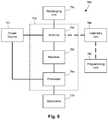
- FIG. 6is a schematic overview of one embodiment of components of an electrical stimulation system 700 including an electronic subassembly 710 disposed within a control module. It will be understood that the electrical stimulation system can include more, fewer, or different components and can have a variety of different configurations including those configurations disclosed in the stimulator references cited herein.
- power source 712can be used including, for example, a battery such as a primary battery or a rechargeable battery.
- a batterysuch as a primary battery or a rechargeable battery.
- other power sourcesinclude super capacitors, nuclear or atomic batteries, mechanical resonators, infrared collectors, thermally-powered energy sources, flexural powered energy sources, bioenergy power sources, fuel cells, bioelectric cells, osmotic pressure pumps, and the like including the power sources described in U.S. Pat. No. 7,437,193, incorporated herein by reference.
- powercan be supplied by an external power source through inductive coupling via the optional antenna 718 or a secondary antenna.
- the external power sourcecan be in a device that is mounted on the skin of the user or in a unit that is provided near the user on a permanent or periodic basis.
- the batterymay be recharged using the optional antenna 718 , if desired. Power can be provided to the battery for recharging by inductively coupling the battery through the antenna to a recharging unit 716 external to the user. Examples of such arrangements can be found in the references identified above.
- electrical currentis emitted by the electrodes 134 on the paddle or lead body to stimulate nerve fibers, muscle fibers, or other body tissues near the electrical stimulation system.
- a processor 704is generally included to control the timing and electrical characteristics of the electrical stimulation system. For example, the processor 704 can, if desired, control one or more of the timing, frequency, strength, duration, and waveform of the pulses. In addition, the processor 704 can select which electrodes can be used to provide stimulation, if desired. In some embodiments, the processor 704 may select which electrode(s) are cathodes and which electrode(s) are anodes. In some embodiments, the processor 704 may be used to identify which electrodes provide the most useful stimulation of the desired tissue.
- Any processorcan be used and can be as simple as an electronic device that, for example, produces pulses at a regular interval or the processor can be capable of receiving and interpreting instructions from an external programming unit 708 that, for example, allows modification of pulse characteristics.
- the processor 704is coupled to a receiver 702 which, in turn, is coupled to the optional antenna 718 . This allows the processor 704 to receive instructions from an external source to, for example, direct the pulse characteristics and the selection of electrodes, if desired.
- the antenna 718is capable of receiving signals (e.g., RF signals) from an external telemetry unit 706 which is programmed by a programming unit 708 .
- the programming unit 708can be external to, or part of, the telemetry unit 706 .
- the telemetry unit 706can be a device that is worn on the skin of the user or can be carried by the user and can have a form similar to a pager, cellular phone, or remote control, if desired.
- the telemetry unit 706may not be worn or carried by the user but may only be available at a home station or at a clinician's office.
- the programming unit 708can be any unit that can provide information to the telemetry unit 706 for transmission to the electrical stimulation system 700 .
- the programming unit 708can be part of the telemetry unit 706 or can provide signals or information to the telemetry unit 706 via a wireless or wired connection.
- One example of a suitable programming unitis a computer operated by the user or clinician to send signals to the telemetry unit 706 .
- the signals sent to the processor 704 via the antenna 718 and receiver 702can be used to modify or otherwise direct the operation of the electrical stimulation system.
- the signalsmay be used to modify the pulses of the electrical stimulation system such as modifying one or more of pulse duration, pulse frequency, pulse waveform, and pulse strength.
- the signalsmay also direct the electrical stimulation system 700 to cease operation, to start operation, to start charging the battery, or to stop charging the battery.
- the stimulation systemdoes not include an antenna 718 or receiver 702 and the processor 704 operates as programmed.
- the electrical stimulation system 700may include a transmitter (not shown) coupled to the processor 704 and the antenna 718 for transmitting signals back to the telemetry unit 706 or another unit capable of receiving the signals.
- the electrical stimulation system 700may transmit signals indicating whether the electrical stimulation system 700 is operating properly or not or indicating when the battery needs to be charged or the level of charge remaining in the battery.
- the processor 704may also be capable of transmitting information about the pulse characteristics so that a user or clinician can determine or verify the characteristics.
Landscapes
- Health & Medical Sciences (AREA)
- Life Sciences & Earth Sciences (AREA)
- General Health & Medical Sciences (AREA)
- Engineering & Computer Science (AREA)
- Biomedical Technology (AREA)
- Nuclear Medicine, Radiotherapy & Molecular Imaging (AREA)
- Animal Behavior & Ethology (AREA)
- Public Health (AREA)
- Veterinary Medicine (AREA)
- Radiology & Medical Imaging (AREA)
- Neurosurgery (AREA)
- Neurology (AREA)
- Heart & Thoracic Surgery (AREA)
- Physics & Mathematics (AREA)
- Surgery (AREA)
- Orthopedic Medicine & Surgery (AREA)
- Cardiology (AREA)
- Acoustics & Sound (AREA)
- Electromagnetism (AREA)
- Pain & Pain Management (AREA)
- Pathology (AREA)
- Medical Informatics (AREA)
- Molecular Biology (AREA)
- Electrotherapy Devices (AREA)
Abstract
Description
Claims (20)
Priority Applications (1)
| Application Number | Priority Date | Filing Date | Title |
|---|---|---|---|
| US15/656,734US10709888B2 (en) | 2016-07-29 | 2017-07-21 | Systems and methods for making and using an electrical stimulation system for peripheral nerve stimulation |
Applications Claiming Priority (2)
| Application Number | Priority Date | Filing Date | Title |
|---|---|---|---|
| US201662368658P | 2016-07-29 | 2016-07-29 | |
| US15/656,734US10709888B2 (en) | 2016-07-29 | 2017-07-21 | Systems and methods for making and using an electrical stimulation system for peripheral nerve stimulation |
Publications (2)
| Publication Number | Publication Date |
|---|---|
| US20180028804A1 US20180028804A1 (en) | 2018-02-01 |
| US10709888B2true US10709888B2 (en) | 2020-07-14 |
Family
ID=59523257
Family Applications (1)
| Application Number | Title | Priority Date | Filing Date |
|---|---|---|---|
| US15/656,734Active2037-11-29US10709888B2 (en) | 2016-07-29 | 2017-07-21 | Systems and methods for making and using an electrical stimulation system for peripheral nerve stimulation |
Country Status (3)
| Country | Link |
|---|---|
| US (1) | US10709888B2 (en) |
| EP (1) | EP3452163A1 (en) |
| WO (1) | WO2018022460A1 (en) |
Cited By (5)
| Publication number | Priority date | Publication date | Assignee | Title |
|---|---|---|---|---|
| WO2022159375A1 (en) | 2021-01-19 | 2022-07-28 | Boston Scientific Neuromodulation Corporation | Electrical stimulation cuff devices and systems with directional electrode configurations |
| WO2022245931A1 (en) | 2021-05-21 | 2022-11-24 | Boston Scientific Neuromodulation Corporation | Electrical stimulation cuff devices and systems with helical arrangement of electrodes |
| WO2025064354A1 (en) | 2023-09-21 | 2025-03-27 | Boston Scientific Neuromodulation Corporation | Electrical stimulation cuff devices and systems and electrode arrangements therefor |
| US12357792B2 (en) | 2019-01-04 | 2025-07-15 | Shifamed Holdings, Llc | Internal recharging systems and methods of use |
| US12440656B2 (en) | 2021-04-23 | 2025-10-14 | Shifamed Holdings, Llc | Power management for interatrial shunts and associated systems and methods |
Families Citing this family (11)
| Publication number | Priority date | Publication date | Assignee | Title |
|---|---|---|---|---|
| US8083685B2 (en) | 2007-05-08 | 2011-12-27 | Propep, Llc | System and method for laparoscopic nerve detection |
| US9743884B2 (en) | 2010-04-30 | 2017-08-29 | J3G Spine, Llc | Devices and methods for nerve mapping |
| WO2016014444A1 (en) | 2014-07-21 | 2016-01-28 | ProPep Surgical, LLC | System and method for laparoscopic nerve identification, nerve location marking, and nerve location recognition |
| CA2959330C (en) | 2014-08-26 | 2022-12-13 | Avent, Inc. | Selective nerve fiber block method and system |
| US10328268B2 (en) | 2014-09-04 | 2019-06-25 | AtaCor Medical, Inc. | Cardiac pacing |
| US10743960B2 (en) | 2014-09-04 | 2020-08-18 | AtaCor Medical, Inc. | Cardiac arrhythmia treatment devices and delivery |
| US11097109B2 (en) | 2014-11-24 | 2021-08-24 | AtaCor Medical, Inc. | Cardiac pacing sensing and control |
| US10792496B2 (en) | 2018-03-15 | 2020-10-06 | Avent, Inc. | System and method to percutaneously block painful sensations |
| WO2019200270A1 (en)* | 2018-04-12 | 2019-10-17 | Robinson David J | Devices and methods for improving headache disorders |
| EP4527449A3 (en) | 2019-05-29 | 2025-04-30 | Atacor Medical, Inc. | Implantable electrical leads and associated delivery systems |
| US11666771B2 (en) | 2020-05-29 | 2023-06-06 | AtaCor Medical, Inc. | Implantable electrical leads and associated delivery systems |
Citations (190)
| Publication number | Priority date | Publication date | Assignee | Title |
|---|---|---|---|---|
| US3769984A (en) | 1971-03-11 | 1973-11-06 | Sherwood Medical Ind Inc | Pacing catheter with frictional fit lead attachment |
| US3941136A (en) | 1973-11-21 | 1976-03-02 | Neuronyx Corporation | Method for artificially inducing urination, defecation, or sexual excitation |
| US4033357A (en) | 1975-02-07 | 1977-07-05 | Medtronic, Inc. | Non-fibrosing cardiac electrode |
| US4135518A (en) | 1976-05-21 | 1979-01-23 | Medtronic, Inc. | Body implantable lead and electrode |
| US4257428A (en) | 1977-12-09 | 1981-03-24 | Barton Steven A | Retractable stimulation electrode apparatus and method |
| US4301815A (en) | 1980-01-23 | 1981-11-24 | Telectronics Pty. Limited | Trailing tine electrode lead |
| US4409994A (en) | 1981-06-02 | 1983-10-18 | Telectronics Pty., Ltd. | Lap joint molding member for a pacemaker electrode lead |
| US4475560A (en) | 1982-04-29 | 1984-10-09 | Cordis Corporation | Temporary pacing lead assembly |
| US4506679A (en) | 1982-09-30 | 1985-03-26 | Mann Alfred E | Endocardial electrode |
| US4542753A (en) | 1982-12-22 | 1985-09-24 | Biosonics, Inc. | Apparatus and method for stimulating penile erectile tissue |
| US4585005A (en) | 1984-04-06 | 1986-04-29 | Regents Of University Of California | Method and pacemaker for stimulating penile erection |
| US4628944A (en) | 1982-02-08 | 1986-12-16 | Cordis Corporation | Cardiac pacing lead with biodegradable fixation structure |
| EP0234457A2 (en) | 1986-02-24 | 1987-09-02 | Medtronic, Inc. | Intramuscular lead |
| US4702254A (en) | 1983-09-14 | 1987-10-27 | Jacob Zabara | Neurocybernetic prosthesis |
| US4716888A (en) | 1985-06-17 | 1988-01-05 | Cordis Corporation | Tined leads |
| US4722353A (en) | 1985-09-16 | 1988-02-02 | Intermedics, Inc. | Stabilizer for implantable electrode |
| US4796643A (en) | 1986-09-30 | 1989-01-10 | Telectronics N.V. | Medical electrode leads |
| US4867164A (en) | 1983-09-14 | 1989-09-19 | Jacob Zabara | Neurocybernetic prosthesis |
| US4920979A (en) | 1988-10-12 | 1990-05-01 | Huntington Medical Research Institute | Bidirectional helical electrode for nerve stimulation |
| US4934368A (en) | 1988-01-21 | 1990-06-19 | Myo/Kinetics Systems, Inc. | Multi-electrode neurological stimulation apparatus |
| US4957118A (en) | 1988-01-15 | 1990-09-18 | Jay Erlebacher | Electrode lead |
| US5025807A (en) | 1983-09-14 | 1991-06-25 | Jacob Zabara | Neurocybernetic prosthesis |
| US5095905A (en) | 1990-06-07 | 1992-03-17 | Medtronic, Inc. | Implantable neural electrode |
| US5139539A (en) | 1981-12-15 | 1992-08-18 | Minnesota Mining And Manufacturing Company | Alumina bonded abrasive for cast iron |
| US5143067A (en) | 1990-06-07 | 1992-09-01 | Medtronic, Inc. | Tool for implantable neural electrode |
| US5193539A (en) | 1991-12-18 | 1993-03-16 | Alfred E. Mann Foundation For Scientific Research | Implantable microstimulator |
| US5193540A (en) | 1991-12-18 | 1993-03-16 | Alfred E. Mann Foundation For Scientific Research | Structure and method of manufacture of an implantable microstimulator |
| US5239540A (en) | 1990-11-27 | 1993-08-24 | Scientific-Atlanta, Inc. | Method and apparatus for transmitting, receiving and communicating digital data signals with corresponding program data signals which describe the digital data signals |
| US5251634A (en) | 1991-05-03 | 1993-10-12 | Cyberonics, Inc. | Helical nerve electrode |
| US5257634A (en) | 1992-07-16 | 1993-11-02 | Angeion Corporation | Low impedence defibrillation catheter electrode |
| US5312439A (en) | 1991-12-12 | 1994-05-17 | Loeb Gerald E | Implantable device having an electrolytic storage electrode |
| US5314457A (en) | 1993-04-08 | 1994-05-24 | Jeutter Dean C | Regenerative electrical |
| US5324327A (en) | 1991-12-17 | 1994-06-28 | Cohen Donald M | Low threshold cardiac pacing lead |
| US5324322A (en) | 1992-04-20 | 1994-06-28 | Case Western Reserve University | Thin film implantable electrode and method of manufacture |
| US5376108A (en) | 1993-05-20 | 1994-12-27 | Telectronics Pacing Systems, Inc. | Electrode lead anchoring apparatus and method employing dual suture collars |
| US5423876A (en)* | 1993-12-09 | 1995-06-13 | Medtronic, Inc. | Intramuscular lead having improved insertion |
| US5433735A (en) | 1993-09-27 | 1995-07-18 | Zanakis; Michael F. | Electrical stimulation technique for tissue regeneration |
| US5439938A (en) | 1993-04-07 | 1995-08-08 | The Johns Hopkins University | Treatments for male sexual dysfunction |
| US5454840A (en) | 1994-04-05 | 1995-10-03 | Krakovsky; Alexander A. | Potency package |
| US5480420A (en) | 1993-09-24 | 1996-01-02 | Siemens Elema Ab | Resorbable temporary medical electrode device |
| US5487756A (en) | 1994-12-23 | 1996-01-30 | Simon Fraser University | Implantable cuff having improved closure |
| US5531781A (en) | 1993-11-02 | 1996-07-02 | Alferness; Clifton A. | Implantable lead having a steering distal guide tip |
| US5571118A (en) | 1995-01-05 | 1996-11-05 | Boutos; David | Apparatus for stimulating penile, scrotal, anal, vaginal and clitoral tissue |
| EP0778047A2 (en) | 1995-11-07 | 1997-06-11 | Medtronic, Inc. | Intramuscular stimulation lead with enhanced infection resistance |
| US5741319A (en) | 1995-01-27 | 1998-04-21 | Medtronic, Inc. | Biocompatible medical lead |
| US5755762A (en) | 1996-06-14 | 1998-05-26 | Pacesetter, Inc. | Medical lead and method of making and using |
| US5775331A (en) | 1995-06-07 | 1998-07-07 | Uromed Corporation | Apparatus and method for locating a nerve |
| WO1998037926A1 (en) | 1997-02-26 | 1998-09-03 | Alfred E. Mann Foundation For Scientific Research | Battery-powered patient implantable device |
| WO1998043700A1 (en) | 1997-03-27 | 1998-10-08 | Alfred E. Mann Foundation For Scientific Research | System of implantable devices for monitoring and/or affecting body parameters |
| US5871530A (en) | 1997-04-29 | 1999-02-16 | Medtronic, Inc. | Intracardiac defibrillation leads |
| US5876399A (en) | 1997-05-28 | 1999-03-02 | Irvine Biomedical, Inc. | Catheter system and methods thereof |
| US5919220A (en) | 1994-09-16 | 1999-07-06 | Fraunhofer Gesellschaft Zur Foerderung Der Angewandten Forschung E.V. | Cuff electrode |
| US5919222A (en) | 1998-01-06 | 1999-07-06 | Medtronic Inc. | Adjustable medical electrode lead |
| US5922015A (en) | 1996-03-14 | 1999-07-13 | Biotronik Mess- Und Therapiegeraete Gmbh & Co. Ingenieurbuero Berlin | Implantable device which permits removal without traumatizing the surrounding tissue |
| US5938584A (en) | 1997-11-14 | 1999-08-17 | Cybernetic Medical Systems Corporation | Cavernous nerve stimulation device |
| US6051017A (en) | 1996-02-20 | 2000-04-18 | Advanced Bionics Corporation | Implantable microstimulator and systems employing the same |
| US6058332A (en) | 1996-10-15 | 2000-05-02 | Angeion Corp. | System for anchoring mid-lead electrode on an endocardial catheter lead |
| US6061596A (en) | 1995-11-24 | 2000-05-09 | Advanced Bionics Corporation | Method for conditioning pelvic musculature using an implanted microstimulator |
| US6151526A (en) | 1998-04-29 | 2000-11-21 | Advanced Bionics Corporation | Ribbed electrode for cochlear stimulation |
| US6175710B1 (en) | 1991-07-06 | 2001-01-16 | Fujitsu Limited | Electrophotographic recording apparatus using developing device with one-component type developer and having combination of charge injection effect and conductive contact type charger |
| US6181969B1 (en) | 1998-06-26 | 2001-01-30 | Advanced Bionics Corporation | Programmable current output stimulus stage for implantable device |
| US6181973B1 (en) | 1999-04-02 | 2001-01-30 | Claudio Ceron | Anchoring structure for implantable electrodes |
| US6188932B1 (en) | 1996-11-13 | 2001-02-13 | Pacesetter Ab | Implantable electrode lead |
| US6201994B1 (en) | 1997-09-02 | 2001-03-13 | Medtronic, Inc. | Single pass lead and method of use |
| US6224450B1 (en) | 1998-08-28 | 2001-05-01 | Laurie J. Norton | Cycling activity belt |
| US6271094B1 (en) | 2000-02-14 | 2001-08-07 | International Business Machines Corporation | Method of making MOSFET with high dielectric constant gate insulator and minimum overlap capacitance |
| US6278897B1 (en) | 1998-12-03 | 2001-08-21 | Medtronic, Inc | Medical electrical lead and introducer system |
| US6292703B1 (en) | 1998-10-08 | 2001-09-18 | Biotronik Mess-Und Therapiegerate Gmbh & Co. | Neural electrode arrangement |
| US6295944B1 (en) | 2000-06-20 | 2001-10-02 | J Timothy Lovett | Automatic tethering system for a floating dock |
| US6308105B1 (en) | 1999-07-15 | 2001-10-23 | Medtronic Inc. | Medical electrical stimulation system using an electrode assembly having opposing semi-circular arms |
| US6315721B2 (en) | 1997-02-26 | 2001-11-13 | Alfred E. Mann Foundation For Scientific Research | System of implantable devices for monitoring and/or affecting body parameters |
| US20020022873A1 (en)* | 2000-08-10 | 2002-02-21 | Erickson John H. | Stimulation/sensing lead adapted for percutaneous insertion |
| US6364278B1 (en) | 1999-11-05 | 2002-04-02 | Hon Hai Precision Ind. Co., Ltd. | Stand for supporting a computer |
| US6391985B1 (en) | 1999-10-21 | 2002-05-21 | Union Carbide Chemicals & Plastics Technology Corporation | High condensing mode polyolefin production under turbulent conditions in a fluidized bed |
| US6456866B1 (en) | 1999-09-28 | 2002-09-24 | Dustin Tyler | Flat interface nerve electrode and a method for use |
| US6463335B1 (en) | 1999-10-04 | 2002-10-08 | Medtronic, Inc. | Temporary medical electrical lead having electrode mounting pad with biodegradable adhesive |
| US6516227B1 (en) | 1999-07-27 | 2003-02-04 | Advanced Bionics Corporation | Rechargeable spinal cord stimulator system |
| US20030040785A1 (en) | 2001-08-21 | 2003-02-27 | Maschino Steve E. | Circumneural electrode assembly |
| US20030045919A1 (en) | 2001-08-31 | 2003-03-06 | Swoyer John Matthew | Implantable medical electrical stimulation lead fixation method and apparatus |
| US20030074039A1 (en) | 1999-06-25 | 2003-04-17 | Puskas John D. | Devices and methods for vagus nerve stimulation |
| US20030078623A1 (en) | 2001-10-22 | 2003-04-24 | Weinberg Lisa P. | Implantable lead and method for stimulating the vagus nerve |
| US20030114905A1 (en) | 1999-10-01 | 2003-06-19 | Kuzma Janusz A. | Implantable microdevice with extended lead and remote electrode |
| US6584363B2 (en) | 1999-03-29 | 2003-06-24 | Cardiac Pacemakers, Inc. | Implantable lead with dissolvable coating for improved fixation and extraction |
| US6582441B1 (en) | 2000-02-24 | 2003-06-24 | Advanced Bionics Corporation | Surgical insertion tool |
| US6609032B1 (en) | 1999-01-07 | 2003-08-19 | Advanced Bionics Corporation | Fitting process for a neural stimulation system |
| US6609029B1 (en) | 2000-02-04 | 2003-08-19 | Advanced Bionics Corporation | Clip lock mechanism for retaining lead |
| US20030199938A1 (en) | 2002-04-22 | 2003-10-23 | Karel Smits | Precise cardiac lead placement based on impedance measurements |
| US6643546B2 (en) | 2001-02-13 | 2003-11-04 | Quetzal Biomedical, Inc. | Multi-electrode apparatus and method for treatment of congestive heart failure |
| US6650943B1 (en) | 2000-04-07 | 2003-11-18 | Advanced Bionics Corporation | Fully implantable neurostimulator for cavernous nerve stimulation as a therapy for erectile dysfunction and other sexual dysfunction |
| US20030236558A1 (en) | 2002-06-20 | 2003-12-25 | Whitehurst Todd K. | Vagus nerve stimulation via unidirectional propagation of action potentials |
| US20040010303A1 (en) | 2001-09-26 | 2004-01-15 | Cvrx, Inc. | Electrode structures and methods for their use in cardiovascular reflex control |
| US20040034401A1 (en) | 2000-12-20 | 2004-02-19 | Kenneth Dahlberg | Electrode head fixation arrangement |
| US20040059392A1 (en) | 2002-06-28 | 2004-03-25 | Jordi Parramon | Microstimulator having self-contained power source |
| US6735474B1 (en) | 1998-07-06 | 2004-05-11 | Advanced Bionics Corporation | Implantable stimulator system and method for treatment of incontinence and pain |
| US6741892B1 (en) | 2000-03-10 | 2004-05-25 | Advanced Bionics Corporation | Movable contact locking mechanism for spinal cord stimulator lead connector |
| US20040111139A1 (en) | 2002-12-10 | 2004-06-10 | Mccreery Douglas B. | Apparatus and methods for differential stimulation of nerve fibers |
| US6788975B1 (en) | 2001-01-30 | 2004-09-07 | Advanced Bionics Corporation | Fully implantable miniature neurostimulator for stimulation as a therapy for epilepsy |
| US20040230280A1 (en) | 2003-04-11 | 2004-11-18 | Cates Adam W. | Helical fixation elements for subcutaneous electrodes |
| US20050010265A1 (en) | 2003-04-02 | 2005-01-13 | Neurostream Technologies Inc. | Fully implantable nerve signal sensing and stimulation device and method for treating foot drop and other neurological disorders |
| US20050065589A1 (en) | 2003-07-25 | 2005-03-24 | Schneider Richard Lee | Method and anchor for medical implant placement, and method of anchor manufacture |
| US20050177220A1 (en) | 2004-02-05 | 2005-08-11 | Medtronic, Inc. | Novel lead fixation means |
| US20050182472A1 (en) | 2004-02-04 | 2005-08-18 | Wahlstrom Dale A. | Novel lead retention means |
| US7003352B1 (en) | 2002-05-24 | 2006-02-21 | Advanced Bionics Corporation | Treatment of epilepsy by brain stimulation |
| US7006875B1 (en) | 2003-03-26 | 2006-02-28 | Advanced Bionics Corporation | Curved paddle electrode for use with a neurostimulator |
| US20060161204A1 (en) | 2005-01-20 | 2006-07-20 | Advanced Bionics Corporation | Implantable microstimulator with plastic housing and methods of manufacture and use |
| US20060184204A1 (en) | 2005-02-11 | 2006-08-17 | Advanced Bionics Corporation | Implantable microstimulator having a separate battery unit and methods of use thereof |
| US20060212075A1 (en) | 2005-03-18 | 2006-09-21 | Marnfeldt Goran N | Implantable microstimulator with conductive plastic electrode and methods of manufacture and use |
| US20060241737A1 (en) | 2005-04-26 | 2006-10-26 | Cardiac Pacemakers, Inc. | Fixation device for coronary venous lead |
| US20060282145A1 (en) | 2005-06-13 | 2006-12-14 | Cardiac Pacemakers, Inc. | Vascularly stabilized peripheral nerve cuff assembly |
| US7203548B2 (en) | 2002-06-20 | 2007-04-10 | Advanced Bionics Corporation | Cavernous nerve stimulation via unidirectional propagation of action potentials |
| US20070150036A1 (en) | 2005-12-27 | 2007-06-28 | Advanced Bionics Corporation | Stimulator leads and methods for lead fabrication |
| US7244150B1 (en) | 2006-01-09 | 2007-07-17 | Advanced Bionics Corporation | Connector and methods of fabrication |
| US7248930B1 (en) | 1997-03-17 | 2007-07-24 | Medtronic, Inc. | Medical electrical lead |
| US20070219595A1 (en) | 2006-03-14 | 2007-09-20 | Advanced Bionics Corporation | Stimulator system with electrode array and the method of making the same |
| WO2008019483A1 (en) | 2006-08-14 | 2008-02-21 | Med-El Elektro-Medizinische Geräte Gesellschaft M.B.H. | Implantable medical cuff with electrode array |
| US20080046055A1 (en) | 2006-08-15 | 2008-02-21 | Durand Dominique M | nerve cuff for implantable electrode |
| US20080071320A1 (en) | 2006-09-18 | 2008-03-20 | Advanced Bionics Corporation | Feed through interconnect assembly for an implantable stimulation system and methods of making and using |
| WO2008048471A2 (en) | 2006-10-13 | 2008-04-24 | Apnex Medical, Inc. | Obstructive sleep apnea treatment devices, systems and methods |
| US7450997B1 (en) | 2000-12-29 | 2008-11-11 | Boston Scientific Neuromodulation Corporation | Method of implanting a lead for brain stimulation |
| US7460913B2 (en) | 2004-05-10 | 2008-12-02 | Boston Scientific Neuromodulation Corporation | Implantable electrode, insertion tool for use therewith, and insertion method |
| US20090118727A1 (en) | 2007-11-05 | 2009-05-07 | Robert Pearson | Ablation devices and methods of using the same |
| US20090187222A1 (en) | 2008-01-23 | 2009-07-23 | Boston Scientific Neuromodulation Corporation | Steerable stylet handle assembly |
| US7596414B2 (en) | 2005-12-05 | 2009-09-29 | Boston Scientific Neuromodulation Corporation | Cuff electrode arrangement for nerve stimulation and methods of treating disorders |
| US7610103B2 (en) | 2005-12-19 | 2009-10-27 | Boston Scientific Neuromodulation Corporation | Electrode arrangement for nerve stimulation and methods of treating disorders |
| US20090276021A1 (en) | 2008-04-30 | 2009-11-05 | Boston Scientific Neuromodulation Corporation | Electrodes for stimulation leads and methods of manufacture and use |
| US20090287271A1 (en) | 2008-05-15 | 2009-11-19 | Intelect Medical, Inc. | Clinician programmer system and method for calculating volumes of activation |
| US7672734B2 (en) | 2005-12-27 | 2010-03-02 | Boston Scientific Neuromodulation Corporation | Non-linear electrode array |
| US20100076535A1 (en) | 2008-09-25 | 2010-03-25 | Boston Scientific Neuromodulation Corporation | Leads with non-circular-shaped distal ends for brain stimulation systems and methods of making and using |
| US7761165B1 (en) | 2005-09-29 | 2010-07-20 | Boston Scientific Neuromodulation Corporation | Implantable stimulator with integrated plastic housing/metal contacts and manufacture and use |
| US7783359B2 (en) | 2005-01-05 | 2010-08-24 | Boston Scientific Neuromodulation Corporation | Devices and methods using an implantable pulse generator for brain stimulation |
| US7809446B2 (en) | 2005-01-05 | 2010-10-05 | Boston Scientific Neuromodulation Corporation | Devices and methods for brain stimulation |
| US20100268298A1 (en) | 2009-04-16 | 2010-10-21 | Boston Scientific Neuromodulation Corporation | Deep brain stimulation current steering with split electrodes |
| US20100298916A1 (en) | 2009-05-22 | 2010-11-25 | Pierre Rabischong | Pelvic implanted neural electrode and method for implanting same |
| US20110005069A1 (en) | 2009-07-07 | 2011-01-13 | Boston Scientific Neuromodulation Corporation | Systems and leads with a radially segmented electrode array and methods of manufacture |
| US20110078900A1 (en) | 2009-07-07 | 2011-04-07 | Boston Scientific Neuromodulation Corporation | Methods for making leads with radially-aligned segmented electrodes for electrical stimulation systems |
| US7953498B1 (en) | 2006-03-15 | 2011-05-31 | Boston Scientific Neuromodulation Corporation | Resorbable anchor arrangements for implantable devices and methods of making and using |
| US20110130803A1 (en) | 2009-11-30 | 2011-06-02 | Boston Scientific Neuromodulation Corporation | Electrode array having concentric windowed cylinder electrodes and methods of making the same |
| US20110130818A1 (en) | 2009-11-30 | 2011-06-02 | Boston Scientific Neuromodulation Corporation | Electrode array having concentric split ring electrodes and methods of making the same |
| US20110130817A1 (en) | 2009-11-30 | 2011-06-02 | Boston Scientific Neuromodulation Corporation | Electrode array having a rail system and methods of manufacturing the same |
| US7974706B2 (en) | 2006-03-30 | 2011-07-05 | Boston Scientific Neuromodulation Corporation | Electrode contact configurations for cuff leads |
| US8019443B2 (en) | 2008-04-01 | 2011-09-13 | Boston Scientific Neuromodulation Corporation | Anchoring units for leads of implantable electric stimulation systems and methods of making and using |
| US20110238129A1 (en) | 2010-03-23 | 2011-09-29 | Boston Scientific Neuromodulation Corporation | Helical radial spacing of contacts on a cylindrical lead |
| US20110313500A1 (en) | 2010-06-18 | 2011-12-22 | Boston Scientific Neuromodulation Corporation | Electrode array having embedded electrodes and methods of making the same |
| US20120016378A1 (en) | 2010-07-16 | 2012-01-19 | Boston Scientific Neuromodulation Corporation | Systems and methods for radial steering of electrode arrays |
| US20120046710A1 (en) | 2010-08-18 | 2012-02-23 | Boston Scientific Neuromodulation Corporation | Methods, systems, and devices for deep brain stimulation using helical movement of the centroid of stimulation |
| US20120071949A1 (en) | 2010-09-21 | 2012-03-22 | Boston Scientific Neuromodulation Corporation | Systems and methods for making and using radially-aligned segmented electrodes for leads of electrical stimulation systems |
| US8155757B1 (en) | 2007-07-26 | 2012-04-10 | Advanced Neuromodulation Systems, Inc. | Cuff electrode having tubular body with controlled closing force |
| US20120165911A1 (en) | 2010-12-23 | 2012-06-28 | Boston Scientific Neuromodulation Corporation | Methods for making leads with segmented electrodes for electrical stimulation systems |
| US20120185027A1 (en) | 2009-04-27 | 2012-07-19 | Boston Scientific Neuromodulation Corporation | Torque lock anchor and methods and devices using the anchor |
| US20120197375A1 (en) | 2011-02-02 | 2012-08-02 | Boston Scientific Neuromodulation Corporation | Leads with spiral of helical segmented electrode arrays and methods of making and using the leads |
| US20120203320A1 (en) | 2011-02-08 | 2012-08-09 | Boston Scientific Neuromodulation Corporation | Leads with spirally arranged segmented electrodes and methods of making and using the leads |
| US20120203321A1 (en) | 2011-02-08 | 2012-08-09 | Boston Scientific Neuromodulation Corporation | Methods for making leads with segmented electrodes for electrical stimulation systems |
| US20120203316A1 (en) | 2011-02-08 | 2012-08-09 | Boston Scientific Neuromodulation Corporation | Leads with segmented electrodes for electrical stimulation of planar regions and methods of making and using |
| US8271094B1 (en) | 2005-09-30 | 2012-09-18 | Boston Scientific Neuromodulation Corporation | Devices with cannula and electrode lead for brain stimulation and methods of use and manufacture |
| US8295944B2 (en) | 2009-11-30 | 2012-10-23 | Boston Scientific Neuromodulation Corporation | Electrode array with electrodes having cutout portions and methods of making the same |
| US20120316615A1 (en) | 2011-06-07 | 2012-12-13 | Boston Scientific Neuromodulation Corporation | Systems and methods for making and using improved leads for electrical stimulation systems |
| US20130023974A1 (en) | 2011-07-22 | 2013-01-24 | Jacob Amrani | Implantable lead with tethers |
| US8364278B2 (en) | 2002-01-29 | 2013-01-29 | Boston Scientific Neuromodulation Corporation | Lead assembly for implantable microstimulator |
| US20130105071A1 (en) | 2011-11-02 | 2013-05-02 | Boston Scientific Neuromodulation Corporation | Systems and methods for making and using improved leads for electrical stimulation systems |
| US20130172973A1 (en) | 2012-01-04 | 2013-07-04 | Bruce A. Tockman | Neural stimulation device with insulating sheath |
| US8483237B2 (en) | 2008-05-28 | 2013-07-09 | Schneider Electric Automation Gmbh | Communication module and method for connecting an electrical device to a network |
| US20130197424A1 (en) | 2006-07-31 | 2013-08-01 | Cranial Medical Systems, Inc. | Lead and methods for brain monitoring and modulation |
| US20130197602A1 (en) | 2012-01-26 | 2013-08-01 | Boston Scientific Neuromodulation Corporation | Systems and methods for identifying the circumferential positioning of electrodes of leads for electrical stimulation systems |
| US20130261684A1 (en) | 2012-03-30 | 2013-10-03 | Boston Scientific Neuromodulation Corporation | Leads with x-ray fluorescent capsules for electrode identification and methods of manufacture and use |
| US8594805B2 (en) | 2011-08-23 | 2013-11-26 | Cardiac Pacemakers, Inc. | Systems to detect vagus capture |
| US20130317587A1 (en) | 2012-05-25 | 2013-11-28 | Boston Scientific Neuromodulation Corporation | Methods for stimulating the dorsal root ganglion with a lead having segmented electrodes |
| US20130317518A1 (en) | 2012-05-25 | 2013-11-28 | Boston Scientific Neuromodulation Corporation | Systems and methods for implanting an electrical stimulation lead using a sheath |
| US20130325091A1 (en) | 2012-06-01 | 2013-12-05 | Boston Scientific Neuromodulation Corporation | Leads with tip electrode for electrical stimulation systems and methods of making and using |
| WO2013188871A1 (en) | 2012-06-15 | 2013-12-19 | Case Western Reserve University | Implantable cuff and method for functional electrical stimulation and monitoring |
| US20140039587A1 (en) | 2012-08-03 | 2014-02-06 | Boston Scientific Neuromodulation Corporation | Leads with electrode carrier for segmented electrodes and methods of making and using |
| US8688235B1 (en) | 2008-07-22 | 2014-04-01 | Boston Scientific Neuromodulation Corporation | Lead with transition and methods of manufacture and use |
| US8718790B2 (en) | 2012-05-25 | 2014-05-06 | Boston Scientific Neuromodulation Corporation | Systems and methods for providing electrical stimulation of multiple dorsal root ganglia with a single lead |
| US8768488B2 (en) | 2012-05-25 | 2014-07-01 | Boston Scientific Neuromodulation Corporation | Systems and methods for electrically stimulating patient tissue on or around one or more bony structures |
| US20140277284A1 (en) | 2013-03-15 | 2014-09-18 | Boston Scientific Neuromodulation Corporation | Clinical response data mapping |
| US8849422B2 (en) | 2012-05-25 | 2014-09-30 | Boston Scientific Neuromodulation Corporation | Percutaneous implantation of an electrical stimulation lead for stimulating dorsal root ganglion |
| US20140358207A1 (en) | 2013-05-31 | 2014-12-04 | Boston Scientific Neuromodulation Corporation | Segmented electrode leads formed from pre-electrodes with depressions or apertures and methods of making and using |
| US20140353001A1 (en) | 2013-05-31 | 2014-12-04 | Boston Scientific Neuromodulation Corporation | Leads containing segmented electrodes with non-perpendicular legs and methods of making and using |
| US20140358209A1 (en) | 2013-05-31 | 2014-12-04 | Boston Scientific Neuromodulation Corporation | Leads with segmented electrodes and methods of making and using the leads |
| US20140358210A1 (en) | 2013-05-31 | 2014-12-04 | Boston Scientific Neuromodulation Corporation | Methods for manufacturing segmented electrode leads using a removable ring and the leads formed thereby |
| US8934992B2 (en) | 2011-09-01 | 2015-01-13 | Inspire Medical Systems, Inc. | Nerve cuff |
| US20150018915A1 (en) | 2013-07-12 | 2015-01-15 | Boston Scientific Neuromodulation Corporation | Leads with segmented electrodes and methods of making and using the leads |
| US20150021817A1 (en) | 2013-07-22 | 2015-01-22 | Boston Scientific Neuromodulation Corporation | Molded segmented electrode leads and systems and methods of manufacturing and using the leads and systems |
| US20150045864A1 (en) | 2013-08-07 | 2015-02-12 | Boston Scientific Neuromodulation Corporation | Systems and methods for making and using segmented tip electrodes for leads of electrical stimulation systems |
| US20150066120A1 (en) | 2013-08-30 | 2015-03-05 | Boston Scientific Neuromodulation Corporation | Methods of making segmented electrode leads using flanged carrier |
| US20150119965A1 (en) | 2013-10-25 | 2015-04-30 | Boston Scientific Neuromodulation Corporation | Lead anchor with pivotable paddles and systems and methods using the lead anchor |
| US20150151113A1 (en) | 2013-12-02 | 2015-06-04 | Boston Scientific Neuromodulation Corporation | Electrical stimulation leads with helically arranged electrodes and methods of making and using |
| US20150202446A1 (en) | 2014-01-17 | 2015-07-23 | Cardiac Pacemakers, Inc. | Selective nerve stimulation using presynaptic terminal depletion block |
| US20150202433A1 (en) | 2014-01-17 | 2015-07-23 | Cardiac Pacemakers, Inc. | Method and apparatus for directed propagation of neural stimulation |
| US20150366467A1 (en) | 2014-06-19 | 2015-12-24 | Cardiac Pacemakers, Inc. | Baroreceptor mapping system |
| US20170224982A1 (en) | 2016-02-05 | 2017-08-10 | Boston Scientific Neuromodulation Corporation | Slotted sleeve neurostimulation device |
- 2017
- 2017-07-21WOPCT/US2017/043333patent/WO2018022460A1/ennot_activeCeased
- 2017-07-21USUS15/656,734patent/US10709888B2/enactiveActive
- 2017-07-21EPEP17749000.0Apatent/EP3452163A1/ennot_activeWithdrawn
Patent Citations (220)
| Publication number | Priority date | Publication date | Assignee | Title |
|---|---|---|---|---|
| US3769984A (en) | 1971-03-11 | 1973-11-06 | Sherwood Medical Ind Inc | Pacing catheter with frictional fit lead attachment |
| US3941136A (en) | 1973-11-21 | 1976-03-02 | Neuronyx Corporation | Method for artificially inducing urination, defecation, or sexual excitation |
| US4033357A (en) | 1975-02-07 | 1977-07-05 | Medtronic, Inc. | Non-fibrosing cardiac electrode |
| US4135518A (en) | 1976-05-21 | 1979-01-23 | Medtronic, Inc. | Body implantable lead and electrode |
| US4257428A (en) | 1977-12-09 | 1981-03-24 | Barton Steven A | Retractable stimulation electrode apparatus and method |
| US4301815A (en) | 1980-01-23 | 1981-11-24 | Telectronics Pty. Limited | Trailing tine electrode lead |
| US4409994A (en) | 1981-06-02 | 1983-10-18 | Telectronics Pty., Ltd. | Lap joint molding member for a pacemaker electrode lead |
| US5139539A (en) | 1981-12-15 | 1992-08-18 | Minnesota Mining And Manufacturing Company | Alumina bonded abrasive for cast iron |
| US4628944A (en) | 1982-02-08 | 1986-12-16 | Cordis Corporation | Cardiac pacing lead with biodegradable fixation structure |
| US4475560A (en) | 1982-04-29 | 1984-10-09 | Cordis Corporation | Temporary pacing lead assembly |
| US4506679A (en) | 1982-09-30 | 1985-03-26 | Mann Alfred E | Endocardial electrode |
| US4542753A (en) | 1982-12-22 | 1985-09-24 | Biosonics, Inc. | Apparatus and method for stimulating penile erectile tissue |
| US4702254A (en) | 1983-09-14 | 1987-10-27 | Jacob Zabara | Neurocybernetic prosthesis |
| US4867164A (en) | 1983-09-14 | 1989-09-19 | Jacob Zabara | Neurocybernetic prosthesis |
| US5025807A (en) | 1983-09-14 | 1991-06-25 | Jacob Zabara | Neurocybernetic prosthesis |
| US4585005A (en) | 1984-04-06 | 1986-04-29 | Regents Of University Of California | Method and pacemaker for stimulating penile erection |
| US4716888A (en) | 1985-06-17 | 1988-01-05 | Cordis Corporation | Tined leads |
| US4722353A (en) | 1985-09-16 | 1988-02-02 | Intermedics, Inc. | Stabilizer for implantable electrode |
| EP0234457A2 (en) | 1986-02-24 | 1987-09-02 | Medtronic, Inc. | Intramuscular lead |
| US4735205A (en)* | 1986-02-24 | 1988-04-05 | Medtronic, Inc. | Method and apparatus including a sliding insulation lead for cardiac assistance |
| US4796643A (en) | 1986-09-30 | 1989-01-10 | Telectronics N.V. | Medical electrode leads |
| US4957118A (en) | 1988-01-15 | 1990-09-18 | Jay Erlebacher | Electrode lead |
| US4934368A (en) | 1988-01-21 | 1990-06-19 | Myo/Kinetics Systems, Inc. | Multi-electrode neurological stimulation apparatus |
| US4920979A (en) | 1988-10-12 | 1990-05-01 | Huntington Medical Research Institute | Bidirectional helical electrode for nerve stimulation |
| US5095905A (en) | 1990-06-07 | 1992-03-17 | Medtronic, Inc. | Implantable neural electrode |
| US5143067A (en) | 1990-06-07 | 1992-09-01 | Medtronic, Inc. | Tool for implantable neural electrode |
| US5282468A (en) | 1990-06-07 | 1994-02-01 | Medtronic, Inc. | Implantable neural electrode |
| US5239540A (en) | 1990-11-27 | 1993-08-24 | Scientific-Atlanta, Inc. | Method and apparatus for transmitting, receiving and communicating digital data signals with corresponding program data signals which describe the digital data signals |
| US5251634A (en) | 1991-05-03 | 1993-10-12 | Cyberonics, Inc. | Helical nerve electrode |
| US6175710B1 (en) | 1991-07-06 | 2001-01-16 | Fujitsu Limited | Electrophotographic recording apparatus using developing device with one-component type developer and having combination of charge injection effect and conductive contact type charger |
| US5312439A (en) | 1991-12-12 | 1994-05-17 | Loeb Gerald E | Implantable device having an electrolytic storage electrode |
| US5324327A (en) | 1991-12-17 | 1994-06-28 | Cohen Donald M | Low threshold cardiac pacing lead |
| US5193539A (en) | 1991-12-18 | 1993-03-16 | Alfred E. Mann Foundation For Scientific Research | Implantable microstimulator |
| US5405367A (en) | 1991-12-18 | 1995-04-11 | Alfred E. Mann Foundation For Scientific Research | Structure and method of manufacture of an implantable microstimulator |
| US5193540A (en) | 1991-12-18 | 1993-03-16 | Alfred E. Mann Foundation For Scientific Research | Structure and method of manufacture of an implantable microstimulator |
| US5324322A (en) | 1992-04-20 | 1994-06-28 | Case Western Reserve University | Thin film implantable electrode and method of manufacture |
| US5257634A (en) | 1992-07-16 | 1993-11-02 | Angeion Corporation | Low impedence defibrillation catheter electrode |
| US5439938A (en) | 1993-04-07 | 1995-08-08 | The Johns Hopkins University | Treatments for male sexual dysfunction |
| US5314457A (en) | 1993-04-08 | 1994-05-24 | Jeutter Dean C | Regenerative electrical |
| US5376108A (en) | 1993-05-20 | 1994-12-27 | Telectronics Pacing Systems, Inc. | Electrode lead anchoring apparatus and method employing dual suture collars |
| US5480420A (en) | 1993-09-24 | 1996-01-02 | Siemens Elema Ab | Resorbable temporary medical electrode device |
| US5433735A (en) | 1993-09-27 | 1995-07-18 | Zanakis; Michael F. | Electrical stimulation technique for tissue regeneration |
| US5531781A (en) | 1993-11-02 | 1996-07-02 | Alferness; Clifton A. | Implantable lead having a steering distal guide tip |
| US5423876A (en)* | 1993-12-09 | 1995-06-13 | Medtronic, Inc. | Intramuscular lead having improved insertion |
| US5454840A (en) | 1994-04-05 | 1995-10-03 | Krakovsky; Alexander A. | Potency package |
| US5919220A (en) | 1994-09-16 | 1999-07-06 | Fraunhofer Gesellschaft Zur Foerderung Der Angewandten Forschung E.V. | Cuff electrode |
| US5487756A (en) | 1994-12-23 | 1996-01-30 | Simon Fraser University | Implantable cuff having improved closure |
| US5571118A (en) | 1995-01-05 | 1996-11-05 | Boutos; David | Apparatus for stimulating penile, scrotal, anal, vaginal and clitoral tissue |
| US5741319A (en) | 1995-01-27 | 1998-04-21 | Medtronic, Inc. | Biocompatible medical lead |
| US5775331A (en) | 1995-06-07 | 1998-07-07 | Uromed Corporation | Apparatus and method for locating a nerve |
| EP0778047A2 (en) | 1995-11-07 | 1997-06-11 | Medtronic, Inc. | Intramuscular stimulation lead with enhanced infection resistance |
| US6061596A (en) | 1995-11-24 | 2000-05-09 | Advanced Bionics Corporation | Method for conditioning pelvic musculature using an implanted microstimulator |
| US6051017A (en) | 1996-02-20 | 2000-04-18 | Advanced Bionics Corporation | Implantable microstimulator and systems employing the same |
| US6175764B1 (en) | 1996-02-20 | 2001-01-16 | Advanced Bionics Corporation | Implantable microstimulator system for producing repeatable patterns of electrical stimulation |
| US6214032B1 (en) | 1996-02-20 | 2001-04-10 | Advanced Bionics Corporation | System for implanting a microstimulator |
| US6185455B1 (en) | 1996-02-20 | 2001-02-06 | Advanced Bionics Corporation | Method of reducing the incidence of medical complications using implantable microstimulators |
| US6181965B1 (en) | 1996-02-20 | 2001-01-30 | Advanced Bionics Corporation | Implantable microstimulator system for prevention of disorders |
| US5922015A (en) | 1996-03-14 | 1999-07-13 | Biotronik Mess- Und Therapiegeraete Gmbh & Co. Ingenieurbuero Berlin | Implantable device which permits removal without traumatizing the surrounding tissue |
| US5755762A (en) | 1996-06-14 | 1998-05-26 | Pacesetter, Inc. | Medical lead and method of making and using |
| US6058332A (en) | 1996-10-15 | 2000-05-02 | Angeion Corp. | System for anchoring mid-lead electrode on an endocardial catheter lead |
| US6188932B1 (en) | 1996-11-13 | 2001-02-13 | Pacesetter Ab | Implantable electrode lead |
| US6185452B1 (en) | 1997-02-26 | 2001-02-06 | Joseph H. Schulman | Battery-powered patient implantable device |
| WO1998037926A1 (en) | 1997-02-26 | 1998-09-03 | Alfred E. Mann Foundation For Scientific Research | Battery-powered patient implantable device |
| US6315721B2 (en) | 1997-02-26 | 2001-11-13 | Alfred E. Mann Foundation For Scientific Research | System of implantable devices for monitoring and/or affecting body parameters |
| US7248930B1 (en) | 1997-03-17 | 2007-07-24 | Medtronic, Inc. | Medical electrical lead |
| WO1998043700A1 (en) | 1997-03-27 | 1998-10-08 | Alfred E. Mann Foundation For Scientific Research | System of implantable devices for monitoring and/or affecting body parameters |
| WO1998043701A1 (en) | 1997-03-27 | 1998-10-08 | Alfred E. Mann Foundation For Scientific Research | System of implantable devices for monitoring and/or affecting body parameters |
| US5871530A (en) | 1997-04-29 | 1999-02-16 | Medtronic, Inc. | Intracardiac defibrillation leads |
| US5876399A (en) | 1997-05-28 | 1999-03-02 | Irvine Biomedical, Inc. | Catheter system and methods thereof |
| US6201994B1 (en) | 1997-09-02 | 2001-03-13 | Medtronic, Inc. | Single pass lead and method of use |
| US5938584A (en) | 1997-11-14 | 1999-08-17 | Cybernetic Medical Systems Corporation | Cavernous nerve stimulation device |
| US5919222A (en) | 1998-01-06 | 1999-07-06 | Medtronic Inc. | Adjustable medical electrode lead |
| US6151526A (en) | 1998-04-29 | 2000-11-21 | Advanced Bionics Corporation | Ribbed electrode for cochlear stimulation |
| US6181969B1 (en) | 1998-06-26 | 2001-01-30 | Advanced Bionics Corporation | Programmable current output stimulus stage for implantable device |
| US6735474B1 (en) | 1998-07-06 | 2004-05-11 | Advanced Bionics Corporation | Implantable stimulator system and method for treatment of incontinence and pain |
| US6224450B1 (en) | 1998-08-28 | 2001-05-01 | Laurie J. Norton | Cycling activity belt |
| US6292703B1 (en) | 1998-10-08 | 2001-09-18 | Biotronik Mess-Und Therapiegerate Gmbh & Co. | Neural electrode arrangement |
| US6278897B1 (en) | 1998-12-03 | 2001-08-21 | Medtronic, Inc | Medical electrical lead and introducer system |
| US6609032B1 (en) | 1999-01-07 | 2003-08-19 | Advanced Bionics Corporation | Fitting process for a neural stimulation system |
| US6584363B2 (en) | 1999-03-29 | 2003-06-24 | Cardiac Pacemakers, Inc. | Implantable lead with dissolvable coating for improved fixation and extraction |
| US6181973B1 (en) | 1999-04-02 | 2001-01-30 | Claudio Ceron | Anchoring structure for implantable electrodes |
| US20030074039A1 (en) | 1999-06-25 | 2003-04-17 | Puskas John D. | Devices and methods for vagus nerve stimulation |
| US6308105B1 (en) | 1999-07-15 | 2001-10-23 | Medtronic Inc. | Medical electrical stimulation system using an electrode assembly having opposing semi-circular arms |
| US6516227B1 (en) | 1999-07-27 | 2003-02-04 | Advanced Bionics Corporation | Rechargeable spinal cord stimulator system |
| US6456866B1 (en) | 1999-09-28 | 2002-09-24 | Dustin Tyler | Flat interface nerve electrode and a method for use |
| US7949395B2 (en) | 1999-10-01 | 2011-05-24 | Boston Scientific Neuromodulation Corporation | Implantable microdevice with extended lead and remote electrode |
| US20030114905A1 (en) | 1999-10-01 | 2003-06-19 | Kuzma Janusz A. | Implantable microdevice with extended lead and remote electrode |
| US6463335B1 (en) | 1999-10-04 | 2002-10-08 | Medtronic, Inc. | Temporary medical electrical lead having electrode mounting pad with biodegradable adhesive |
| US6391985B1 (en) | 1999-10-21 | 2002-05-21 | Union Carbide Chemicals & Plastics Technology Corporation | High condensing mode polyolefin production under turbulent conditions in a fluidized bed |
| US6364278B1 (en) | 1999-11-05 | 2002-04-02 | Hon Hai Precision Ind. Co., Ltd. | Stand for supporting a computer |
| US6609029B1 (en) | 2000-02-04 | 2003-08-19 | Advanced Bionics Corporation | Clip lock mechanism for retaining lead |
| US6271094B1 (en) | 2000-02-14 | 2001-08-07 | International Business Machines Corporation | Method of making MOSFET with high dielectric constant gate insulator and minimum overlap capacitance |
| US6582441B1 (en) | 2000-02-24 | 2003-06-24 | Advanced Bionics Corporation | Surgical insertion tool |
| US6741892B1 (en) | 2000-03-10 | 2004-05-25 | Advanced Bionics Corporation | Movable contact locking mechanism for spinal cord stimulator lead connector |
| US6650943B1 (en) | 2000-04-07 | 2003-11-18 | Advanced Bionics Corporation | Fully implantable neurostimulator for cavernous nerve stimulation as a therapy for erectile dysfunction and other sexual dysfunction |
| US6295944B1 (en) | 2000-06-20 | 2001-10-02 | J Timothy Lovett | Automatic tethering system for a floating dock |
| US20020022873A1 (en)* | 2000-08-10 | 2002-02-21 | Erickson John H. | Stimulation/sensing lead adapted for percutaneous insertion |
| US20040034401A1 (en) | 2000-12-20 | 2004-02-19 | Kenneth Dahlberg | Electrode head fixation arrangement |
| US7792590B1 (en) | 2000-12-29 | 2010-09-07 | Boston Scientific Neuromodulation Corporation | Implantable lead systems for brain stimulation |
| US7450997B1 (en) | 2000-12-29 | 2008-11-11 | Boston Scientific Neuromodulation Corporation | Method of implanting a lead for brain stimulation |
| US6788975B1 (en) | 2001-01-30 | 2004-09-07 | Advanced Bionics Corporation | Fully implantable miniature neurostimulator for stimulation as a therapy for epilepsy |
| US6643546B2 (en) | 2001-02-13 | 2003-11-04 | Quetzal Biomedical, Inc. | Multi-electrode apparatus and method for treatment of congestive heart failure |
| US20030040785A1 (en) | 2001-08-21 | 2003-02-27 | Maschino Steve E. | Circumneural electrode assembly |
| US20030045919A1 (en) | 2001-08-31 | 2003-03-06 | Swoyer John Matthew | Implantable medical electrical stimulation lead fixation method and apparatus |
| US20040010303A1 (en) | 2001-09-26 | 2004-01-15 | Cvrx, Inc. | Electrode structures and methods for their use in cardiovascular reflex control |
| US20030078623A1 (en) | 2001-10-22 | 2003-04-24 | Weinberg Lisa P. | Implantable lead and method for stimulating the vagus nerve |
| US8364278B2 (en) | 2002-01-29 | 2013-01-29 | Boston Scientific Neuromodulation Corporation | Lead assembly for implantable microstimulator |
| US20030199938A1 (en) | 2002-04-22 | 2003-10-23 | Karel Smits | Precise cardiac lead placement based on impedance measurements |
| US7003352B1 (en) | 2002-05-24 | 2006-02-21 | Advanced Bionics Corporation | Treatment of epilepsy by brain stimulation |
| US7292890B2 (en) | 2002-06-20 | 2007-11-06 | Advanced Bionics Corporation | Vagus nerve stimulation via unidirectional propagation of action potentials |
| US7203548B2 (en) | 2002-06-20 | 2007-04-10 | Advanced Bionics Corporation | Cavernous nerve stimulation via unidirectional propagation of action potentials |
| US20030236558A1 (en) | 2002-06-20 | 2003-12-25 | Whitehurst Todd K. | Vagus nerve stimulation via unidirectional propagation of action potentials |
| US7783362B2 (en) | 2002-06-20 | 2010-08-24 | Boston Scientific Neuromodulation Corporation | Vagus nerve stimulation via unidirectional propagation of action potentials |
| US20040059392A1 (en) | 2002-06-28 | 2004-03-25 | Jordi Parramon | Microstimulator having self-contained power source |
| US7437193B2 (en) | 2002-06-28 | 2008-10-14 | Boston Scientific Neuromodulation Corporation | Microstimulator employing improved recharging reporting and telemetry techniques |
| US20040111139A1 (en) | 2002-12-10 | 2004-06-10 | Mccreery Douglas B. | Apparatus and methods for differential stimulation of nerve fibers |
| US7006875B1 (en) | 2003-03-26 | 2006-02-28 | Advanced Bionics Corporation | Curved paddle electrode for use with a neurostimulator |
| US20050010265A1 (en) | 2003-04-02 | 2005-01-13 | Neurostream Technologies Inc. | Fully implantable nerve signal sensing and stimulation device and method for treating foot drop and other neurological disorders |
| US20040230280A1 (en) | 2003-04-11 | 2004-11-18 | Cates Adam W. | Helical fixation elements for subcutaneous electrodes |
| US20050065589A1 (en) | 2003-07-25 | 2005-03-24 | Schneider Richard Lee | Method and anchor for medical implant placement, and method of anchor manufacture |
| US20050182472A1 (en) | 2004-02-04 | 2005-08-18 | Wahlstrom Dale A. | Novel lead retention means |
| US20050177220A1 (en) | 2004-02-05 | 2005-08-11 | Medtronic, Inc. | Novel lead fixation means |
| US7460913B2 (en) | 2004-05-10 | 2008-12-02 | Boston Scientific Neuromodulation Corporation | Implantable electrode, insertion tool for use therewith, and insertion method |
| US20110004267A1 (en) | 2005-01-05 | 2011-01-06 | Boston Scientific Neuromodulation Corporation | Devices and methods for brain stimulation |
| US7809446B2 (en) | 2005-01-05 | 2010-10-05 | Boston Scientific Neuromodulation Corporation | Devices and methods for brain stimulation |
| US7783359B2 (en) | 2005-01-05 | 2010-08-24 | Boston Scientific Neuromodulation Corporation | Devices and methods using an implantable pulse generator for brain stimulation |
| US7706892B2 (en) | 2005-01-20 | 2010-04-27 | Boston Scientific Neuromodulation Corporation | Implantable microstimulator with plastic housing and methods of manufacture and use |
| US20060161204A1 (en) | 2005-01-20 | 2006-07-20 | Advanced Bionics Corporation | Implantable microstimulator with plastic housing and methods of manufacture and use |
| US20060184204A1 (en) | 2005-02-11 | 2006-08-17 | Advanced Bionics Corporation | Implantable microstimulator having a separate battery unit and methods of use thereof |
| US7840279B2 (en) | 2005-02-11 | 2010-11-23 | Boston Scientific Neuromodulation Corporation | Implantable microstimulator having a separate battery unit and methods of use thereof |
| US20060212075A1 (en) | 2005-03-18 | 2006-09-21 | Marnfeldt Goran N | Implantable microstimulator with conductive plastic electrode and methods of manufacture and use |
| US20060241737A1 (en) | 2005-04-26 | 2006-10-26 | Cardiac Pacemakers, Inc. | Fixation device for coronary venous lead |
| US20060282145A1 (en) | 2005-06-13 | 2006-12-14 | Cardiac Pacemakers, Inc. | Vascularly stabilized peripheral nerve cuff assembly |
| US7584004B2 (en) | 2005-06-13 | 2009-09-01 | Cardiac Pacemakers, Inc. | Vascularly stabilized peripheral nerve cuff assembly |
| US7761165B1 (en) | 2005-09-29 | 2010-07-20 | Boston Scientific Neuromodulation Corporation | Implantable stimulator with integrated plastic housing/metal contacts and manufacture and use |
| US8271094B1 (en) | 2005-09-30 | 2012-09-18 | Boston Scientific Neuromodulation Corporation | Devices with cannula and electrode lead for brain stimulation and methods of use and manufacture |
| US7596414B2 (en) | 2005-12-05 | 2009-09-29 | Boston Scientific Neuromodulation Corporation | Cuff electrode arrangement for nerve stimulation and methods of treating disorders |
| US7610103B2 (en) | 2005-12-19 | 2009-10-27 | Boston Scientific Neuromodulation Corporation | Electrode arrangement for nerve stimulation and methods of treating disorders |
| US20070150036A1 (en) | 2005-12-27 | 2007-06-28 | Advanced Bionics Corporation | Stimulator leads and methods for lead fabrication |
| US7672734B2 (en) | 2005-12-27 | 2010-03-02 | Boston Scientific Neuromodulation Corporation | Non-linear electrode array |
| US7244150B1 (en) | 2006-01-09 | 2007-07-17 | Advanced Bionics Corporation | Connector and methods of fabrication |
| US20070219595A1 (en) | 2006-03-14 | 2007-09-20 | Advanced Bionics Corporation | Stimulator system with electrode array and the method of making the same |
| US8175710B2 (en) | 2006-03-14 | 2012-05-08 | Boston Scientific Neuromodulation Corporation | Stimulator system with electrode array and the method of making the same |
| US7953498B1 (en) | 2006-03-15 | 2011-05-31 | Boston Scientific Neuromodulation Corporation | Resorbable anchor arrangements for implantable devices and methods of making and using |
| US7974706B2 (en) | 2006-03-30 | 2011-07-05 | Boston Scientific Neuromodulation Corporation | Electrode contact configurations for cuff leads |
| US20130197424A1 (en) | 2006-07-31 | 2013-08-01 | Cranial Medical Systems, Inc. | Lead and methods for brain monitoring and modulation |
| WO2008019483A1 (en) | 2006-08-14 | 2008-02-21 | Med-El Elektro-Medizinische Geräte Gesellschaft M.B.H. | Implantable medical cuff with electrode array |
| US20100241207A1 (en) | 2006-08-14 | 2010-09-23 | Henry Bluger | Implantable Medical Cuff with Electrode Array |
| US20080046055A1 (en) | 2006-08-15 | 2008-02-21 | Durand Dominique M | nerve cuff for implantable electrode |
| US20080071320A1 (en) | 2006-09-18 | 2008-03-20 | Advanced Bionics Corporation | Feed through interconnect assembly for an implantable stimulation system and methods of making and using |
| US8224450B2 (en) | 2006-09-18 | 2012-07-17 | Boston Scientific Neuromodulation Corporation | Feed through interconnect assembly for an implantable stimulation system and methods of making and using |
| WO2008048471A2 (en) | 2006-10-13 | 2008-04-24 | Apnex Medical, Inc. | Obstructive sleep apnea treatment devices, systems and methods |
| US8155757B1 (en) | 2007-07-26 | 2012-04-10 | Advanced Neuromodulation Systems, Inc. | Cuff electrode having tubular body with controlled closing force |
| US8612025B2 (en) | 2007-07-26 | 2013-12-17 | Advanced Neuromodulation Systems, Inc. | Cuff electrode having tubular body with controlled closing force |
| US20140074213A1 (en) | 2007-07-26 | 2014-03-13 | Advanced Neuromodulation Systems, Inc., D/B/A St. Jude Medical Neuromodulation Division | Cuff electrode having tubular body with controlled closing force |
| US20090118727A1 (en) | 2007-11-05 | 2009-05-07 | Robert Pearson | Ablation devices and methods of using the same |
| US20090187222A1 (en) | 2008-01-23 | 2009-07-23 | Boston Scientific Neuromodulation Corporation | Steerable stylet handle assembly |
| US8019443B2 (en) | 2008-04-01 | 2011-09-13 | Boston Scientific Neuromodulation Corporation | Anchoring units for leads of implantable electric stimulation systems and methods of making and using |
| US20090276021A1 (en) | 2008-04-30 | 2009-11-05 | Boston Scientific Neuromodulation Corporation | Electrodes for stimulation leads and methods of manufacture and use |
| US20090287272A1 (en) | 2008-05-15 | 2009-11-19 | Intelect Medical, Inc. | Clinician programmer system and method for steering volumesof activation |
| US20100049276A1 (en) | 2008-05-15 | 2010-02-25 | Intellect Medical, Inc. | Clinician programmer system and method for calculating volumes of activation for monopolar and bipolar electrode configurations |
| US20090287271A1 (en) | 2008-05-15 | 2009-11-19 | Intelect Medical, Inc. | Clinician programmer system and method for calculating volumes of activation |
| US20090287467A1 (en) | 2008-05-15 | 2009-11-19 | Intellect Medical, Inc. | Clinician programmer system and method for generating interface models and displays of volumes of activation |
| US20090287273A1 (en) | 2008-05-15 | 2009-11-19 | Intelect Medical, Inc. | Clinician programmer system interface for monitoring patient progress |
| US8483237B2 (en) | 2008-05-28 | 2013-07-09 | Schneider Electric Automation Gmbh | Communication module and method for connecting an electrical device to a network |
| US8688235B1 (en) | 2008-07-22 | 2014-04-01 | Boston Scientific Neuromodulation Corporation | Lead with transition and methods of manufacture and use |
| US20100076535A1 (en) | 2008-09-25 | 2010-03-25 | Boston Scientific Neuromodulation Corporation | Leads with non-circular-shaped distal ends for brain stimulation systems and methods of making and using |
| US20100268298A1 (en) | 2009-04-16 | 2010-10-21 | Boston Scientific Neuromodulation Corporation | Deep brain stimulation current steering with split electrodes |
| US20120185027A1 (en) | 2009-04-27 | 2012-07-19 | Boston Scientific Neuromodulation Corporation | Torque lock anchor and methods and devices using the anchor |
| US20100298916A1 (en) | 2009-05-22 | 2010-11-25 | Pierre Rabischong | Pelvic implanted neural electrode and method for implanting same |
| US20110005069A1 (en) | 2009-07-07 | 2011-01-13 | Boston Scientific Neuromodulation Corporation | Systems and leads with a radially segmented electrode array and methods of manufacture |
| US20110078900A1 (en) | 2009-07-07 | 2011-04-07 | Boston Scientific Neuromodulation Corporation | Methods for making leads with radially-aligned segmented electrodes for electrical stimulation systems |
| US20110130818A1 (en) | 2009-11-30 | 2011-06-02 | Boston Scientific Neuromodulation Corporation | Electrode array having concentric split ring electrodes and methods of making the same |
| US20110130817A1 (en) | 2009-11-30 | 2011-06-02 | Boston Scientific Neuromodulation Corporation | Electrode array having a rail system and methods of manufacturing the same |
| US8295944B2 (en) | 2009-11-30 | 2012-10-23 | Boston Scientific Neuromodulation Corporation | Electrode array with electrodes having cutout portions and methods of making the same |
| US20110130803A1 (en) | 2009-11-30 | 2011-06-02 | Boston Scientific Neuromodulation Corporation | Electrode array having concentric windowed cylinder electrodes and methods of making the same |
| US8391985B2 (en) | 2009-11-30 | 2013-03-05 | Boston Scientific Neuromodulation Corporation | Electrode array having concentric windowed cylinder electrodes and methods of making the same |
| US20110238129A1 (en) | 2010-03-23 | 2011-09-29 | Boston Scientific Neuromodulation Corporation | Helical radial spacing of contacts on a cylindrical lead |
| US20110313500A1 (en) | 2010-06-18 | 2011-12-22 | Boston Scientific Neuromodulation Corporation | Electrode array having embedded electrodes and methods of making the same |
| US20120016378A1 (en) | 2010-07-16 | 2012-01-19 | Boston Scientific Neuromodulation Corporation | Systems and methods for radial steering of electrode arrays |
| US20120046710A1 (en) | 2010-08-18 | 2012-02-23 | Boston Scientific Neuromodulation Corporation | Methods, systems, and devices for deep brain stimulation using helical movement of the centroid of stimulation |
| US20120071949A1 (en) | 2010-09-21 | 2012-03-22 | Boston Scientific Neuromodulation Corporation | Systems and methods for making and using radially-aligned segmented electrodes for leads of electrical stimulation systems |
| US20120165911A1 (en) | 2010-12-23 | 2012-06-28 | Boston Scientific Neuromodulation Corporation | Methods for making leads with segmented electrodes for electrical stimulation systems |
| US20120197375A1 (en) | 2011-02-02 | 2012-08-02 | Boston Scientific Neuromodulation Corporation | Leads with spiral of helical segmented electrode arrays and methods of making and using the leads |
| US20120203316A1 (en) | 2011-02-08 | 2012-08-09 | Boston Scientific Neuromodulation Corporation | Leads with segmented electrodes for electrical stimulation of planar regions and methods of making and using |
| US20120203321A1 (en) | 2011-02-08 | 2012-08-09 | Boston Scientific Neuromodulation Corporation | Methods for making leads with segmented electrodes for electrical stimulation systems |
| US20120203320A1 (en) | 2011-02-08 | 2012-08-09 | Boston Scientific Neuromodulation Corporation | Leads with spirally arranged segmented electrodes and methods of making and using the leads |
| US20120316615A1 (en) | 2011-06-07 | 2012-12-13 | Boston Scientific Neuromodulation Corporation | Systems and methods for making and using improved leads for electrical stimulation systems |
| US20130023974A1 (en) | 2011-07-22 | 2013-01-24 | Jacob Amrani | Implantable lead with tethers |
| US8818524B2 (en) | 2011-08-23 | 2014-08-26 | Cardiac Pacemakers, Inc. | Method for detecting vagus capture |
| US8594805B2 (en) | 2011-08-23 | 2013-11-26 | Cardiac Pacemakers, Inc. | Systems to detect vagus capture |
| US8934992B2 (en) | 2011-09-01 | 2015-01-13 | Inspire Medical Systems, Inc. | Nerve cuff |
| US20130105071A1 (en) | 2011-11-02 | 2013-05-02 | Boston Scientific Neuromodulation Corporation | Systems and methods for making and using improved leads for electrical stimulation systems |
| US20130172973A1 (en) | 2012-01-04 | 2013-07-04 | Bruce A. Tockman | Neural stimulation device with insulating sheath |
| US8831742B2 (en) | 2012-01-26 | 2014-09-09 | Boston Scientific Neuromodulation Corporation | Systems and methods for identifying the circumferential positioning of electrodes of leads for electrical stimulation systems |
| US20130197602A1 (en) | 2012-01-26 | 2013-08-01 | Boston Scientific Neuromodulation Corporation | Systems and methods for identifying the circumferential positioning of electrodes of leads for electrical stimulation systems |
| US20130261684A1 (en) | 2012-03-30 | 2013-10-03 | Boston Scientific Neuromodulation Corporation | Leads with x-ray fluorescent capsules for electrode identification and methods of manufacture and use |
| US8718790B2 (en) | 2012-05-25 | 2014-05-06 | Boston Scientific Neuromodulation Corporation | Systems and methods for providing electrical stimulation of multiple dorsal root ganglia with a single lead |
| US20130317587A1 (en) | 2012-05-25 | 2013-11-28 | Boston Scientific Neuromodulation Corporation | Methods for stimulating the dorsal root ganglion with a lead having segmented electrodes |
| US8768488B2 (en) | 2012-05-25 | 2014-07-01 | Boston Scientific Neuromodulation Corporation | Systems and methods for electrically stimulating patient tissue on or around one or more bony structures |
| US20130317518A1 (en) | 2012-05-25 | 2013-11-28 | Boston Scientific Neuromodulation Corporation | Systems and methods for implanting an electrical stimulation lead using a sheath |
| US8849422B2 (en) | 2012-05-25 | 2014-09-30 | Boston Scientific Neuromodulation Corporation | Percutaneous implantation of an electrical stimulation lead for stimulating dorsal root ganglion |
| US20130325091A1 (en) | 2012-06-01 | 2013-12-05 | Boston Scientific Neuromodulation Corporation | Leads with tip electrode for electrical stimulation systems and methods of making and using |
| WO2013188871A1 (en) | 2012-06-15 | 2013-12-19 | Case Western Reserve University | Implantable cuff and method for functional electrical stimulation and monitoring |
| US20140039587A1 (en) | 2012-08-03 | 2014-02-06 | Boston Scientific Neuromodulation Corporation | Leads with electrode carrier for segmented electrodes and methods of making and using |
| US20140277284A1 (en) | 2013-03-15 | 2014-09-18 | Boston Scientific Neuromodulation Corporation | Clinical response data mapping |
| US20140358207A1 (en) | 2013-05-31 | 2014-12-04 | Boston Scientific Neuromodulation Corporation | Segmented electrode leads formed from pre-electrodes with depressions or apertures and methods of making and using |
| US20140358209A1 (en) | 2013-05-31 | 2014-12-04 | Boston Scientific Neuromodulation Corporation | Leads with segmented electrodes and methods of making and using the leads |
| US20140358210A1 (en) | 2013-05-31 | 2014-12-04 | Boston Scientific Neuromodulation Corporation | Methods for manufacturing segmented electrode leads using a removable ring and the leads formed thereby |
| US20140353001A1 (en) | 2013-05-31 | 2014-12-04 | Boston Scientific Neuromodulation Corporation | Leads containing segmented electrodes with non-perpendicular legs and methods of making and using |
| US20150018915A1 (en) | 2013-07-12 | 2015-01-15 | Boston Scientific Neuromodulation Corporation | Leads with segmented electrodes and methods of making and using the leads |
| US20150021817A1 (en) | 2013-07-22 | 2015-01-22 | Boston Scientific Neuromodulation Corporation | Molded segmented electrode leads and systems and methods of manufacturing and using the leads and systems |
| US20150045864A1 (en) | 2013-08-07 | 2015-02-12 | Boston Scientific Neuromodulation Corporation | Systems and methods for making and using segmented tip electrodes for leads of electrical stimulation systems |
| US20150066120A1 (en) | 2013-08-30 | 2015-03-05 | Boston Scientific Neuromodulation Corporation | Methods of making segmented electrode leads using flanged carrier |
| US20150119965A1 (en) | 2013-10-25 | 2015-04-30 | Boston Scientific Neuromodulation Corporation | Lead anchor with pivotable paddles and systems and methods using the lead anchor |
| US20150151113A1 (en) | 2013-12-02 | 2015-06-04 | Boston Scientific Neuromodulation Corporation | Electrical stimulation leads with helically arranged electrodes and methods of making and using |
| US20150202446A1 (en) | 2014-01-17 | 2015-07-23 | Cardiac Pacemakers, Inc. | Selective nerve stimulation using presynaptic terminal depletion block |
| US20150202433A1 (en) | 2014-01-17 | 2015-07-23 | Cardiac Pacemakers, Inc. | Method and apparatus for directed propagation of neural stimulation |
| US20150366467A1 (en) | 2014-06-19 | 2015-12-24 | Cardiac Pacemakers, Inc. | Baroreceptor mapping system |
| US20170224982A1 (en) | 2016-02-05 | 2017-08-10 | Boston Scientific Neuromodulation Corporation | Slotted sleeve neurostimulation device |
Non-Patent Citations (10)
| Title |
|---|
| International Search Report and Written Opinion for PCT/US2017/043333 dated Jan. 5, 2018. |
| Plachta et al., "Blood pressure control with selective vagal nerve stimulation and minimal side effects," J. Neural Eng. 11 (2014) 036011 (15pp), 2014. |
| Polasek et al., "Stimulation Stability and Selectivity of Chronically Implanted Multicontact Nerve Cuff Electrodes in the Human Upper Extremity." IEEE Transactions on Neural Systems and Rehabilitation Engineering, vol. 17, No. 5, 428-437, Oct. 2009. |
| Rattay, F., "Analysis of Models for External Stimulation of Axons," IEEE Transactions on Biomedical Engineering, BME-33(10): 974-977, 1986. |
| Rozman et al., "Selective Stimulation of Autonomic Nerves and Recording of Electroneurograms in a Canine Model," Artificial Organs, 21(8): 592-596, 2008. |
| U.S. Appl. No. 15/436,544, filed Feb. 17, 2017. |
| U.S. Appl. No. 15/601,838, filed May 22, 2017. |
| U.S. Appl. No. 15/608,573, filed May 30, 2017. |
| U.S. Appl. No. 15/656,734, filed Jul. 21, 2017. |
| U.S. Appl. No. 62/429,650, filed Dec. 2, 2016. |
Cited By (6)
| Publication number | Priority date | Publication date | Assignee | Title |
|---|---|---|---|---|
| US12357792B2 (en) | 2019-01-04 | 2025-07-15 | Shifamed Holdings, Llc | Internal recharging systems and methods of use |
| WO2022159375A1 (en) | 2021-01-19 | 2022-07-28 | Boston Scientific Neuromodulation Corporation | Electrical stimulation cuff devices and systems with directional electrode configurations |
| US12440656B2 (en) | 2021-04-23 | 2025-10-14 | Shifamed Holdings, Llc | Power management for interatrial shunts and associated systems and methods |
| WO2022245931A1 (en) | 2021-05-21 | 2022-11-24 | Boston Scientific Neuromodulation Corporation | Electrical stimulation cuff devices and systems with helical arrangement of electrodes |
| US12194291B2 (en) | 2021-05-21 | 2025-01-14 | Boston Scientific Neuromodulation Corporation | Electrical stimulation cuff devices and systems with helical arrangement of electrodes |
| WO2025064354A1 (en) | 2023-09-21 | 2025-03-27 | Boston Scientific Neuromodulation Corporation | Electrical stimulation cuff devices and systems and electrode arrangements therefor |
Also Published As
| Publication number | Publication date |
|---|---|
| EP3452163A1 (en) | 2019-03-13 |
| US20180028804A1 (en) | 2018-02-01 |
| WO2018022460A1 (en) | 2018-02-01 |
Similar Documents
| Publication | Publication Date | Title |
|---|---|---|
| US10709888B2 (en) | Systems and methods for making and using an electrical stimulation system for peripheral nerve stimulation | |
| US11020586B2 (en) | Distally curved electrical stimulation lead and methods of making and using | |
| US9833611B2 (en) | Systems and methods for making and using improved contact arrays for electrical stimulation systems | |
| US10905871B2 (en) | Lead assemblies with arrangements to confirm alignment between terminals and contacts | |
| US9839787B2 (en) | Systems and methods for making and using connector contact arrays for electrical stimulation systems | |
| US10286205B2 (en) | Systems and methods for making and using improved contact arrays for electrical stimulation systems | |
| US9199074B2 (en) | Percutaneous implantation of an electrical stimulation lead for stimulating dorsal root ganglion | |
| US10342983B2 (en) | Systems and methods for making and using connector contact arrays for electrical stimulation systems | |
| US9402993B2 (en) | Systems and methods for enhancing paddle lead placement | |
| US8718790B2 (en) | Systems and methods for providing electrical stimulation of multiple dorsal root ganglia with a single lead | |
| US8849396B2 (en) | Systems and methods for making and using improved connector contacts for electrical stimulation systems | |
| US20180028820A1 (en) | Biased ball-spring contacts for electrical stimulation systems and methods of making and using same | |
| US20120209285A1 (en) | Systems and methods for implanting paddle lead assemblies of electrical stimulation systems | |
| US20140343656A1 (en) | Electrical stimulation leads with anchoring unit and electrode arrangement and methods of making and using | |
| US20140343645A1 (en) | Electrical stimulation leads and systems with anchoring units and methods of making and using | |
| US20180021569A1 (en) | Systems and methods for making and using an electrical stimulation system for stimulation of dorsal root ganglia | |
| US10179234B2 (en) | Distally reinforced lead and methods of making and using | |
| US8849419B2 (en) | Systems and methods for making and using electrodes for enhancing stimulation penetration of patient tissue | |
| US20150051677A1 (en) | Control module with port for receiving one or two leads and systems and methods using the control module |
Legal Events
| Date | Code | Title | Description |
|---|---|---|---|
| AS | Assignment | Owner name:BOSTON SCIENTIFIC NEUROMODULATION CORPORATION, CALIFORNIA Free format text:ASSIGNMENT OF ASSIGNORS INTEREST;ASSIGNOR:PIANCA, ANNE MARGARET;REEL/FRAME:043067/0389 Effective date:20170608 Owner name:BOSTON SCIENTIFIC NEUROMODULATION CORPORATION, CAL Free format text:ASSIGNMENT OF ASSIGNORS INTEREST;ASSIGNOR:PIANCA, ANNE MARGARET;REEL/FRAME:043067/0389 Effective date:20170608 | |
| STPP | Information on status: patent application and granting procedure in general | Free format text:NON FINAL ACTION MAILED | |
| STPP | Information on status: patent application and granting procedure in general | Free format text:RESPONSE TO NON-FINAL OFFICE ACTION ENTERED AND FORWARDED TO EXAMINER | |
| STPP | Information on status: patent application and granting procedure in general | Free format text:FINAL REJECTION MAILED | |
| STPP | Information on status: patent application and granting procedure in general | Free format text:ADVISORY ACTION MAILED | |
| STPP | Information on status: patent application and granting procedure in general | Free format text:AWAITING TC RESP., ISSUE FEE NOT PAID | |
| STPP | Information on status: patent application and granting procedure in general | Free format text:PUBLICATIONS -- ISSUE FEE PAYMENT VERIFIED | |
| STCF | Information on status: patent grant | Free format text:PATENTED CASE | |
| MAFP | Maintenance fee payment | Free format text:PAYMENT OF MAINTENANCE FEE, 4TH YEAR, LARGE ENTITY (ORIGINAL EVENT CODE: M1551); ENTITY STATUS OF PATENT OWNER: LARGE ENTITY Year of fee payment:4 |