US10709886B2 - Electrical stimulation leads and systems with elongate anchoring elements and methods of making and using - Google Patents
Electrical stimulation leads and systems with elongate anchoring elements and methods of making and usingDownload PDFInfo
- Publication number
- US10709886B2 US10709886B2US15/905,398US201815905398AUS10709886B2US 10709886 B2US10709886 B2US 10709886B2US 201815905398 AUS201815905398 AUS 201815905398AUS 10709886 B2US10709886 B2US 10709886B2
- Authority
- US
- United States
- Prior art keywords
- lead
- anchoring
- anchoring element
- electrical stimulation
- attachment member
- Prior art date
- Legal status (The legal status is an assumption and is not a legal conclusion. Google has not performed a legal analysis and makes no representation as to the accuracy of the status listed.)
- Active, expires
Links
- 0CC(**1IICC1)C(C1C)C1=[*+]Chemical compoundCC(**1IICC1)C(C1C)C1=[*+]0.000description1
Images


Classifications
- A—HUMAN NECESSITIES
- A61—MEDICAL OR VETERINARY SCIENCE; HYGIENE
- A61N—ELECTROTHERAPY; MAGNETOTHERAPY; RADIATION THERAPY; ULTRASOUND THERAPY
- A61N1/00—Electrotherapy; Circuits therefor
- A61N1/02—Details
- A61N1/04—Electrodes
- A61N1/05—Electrodes for implantation or insertion into the body, e.g. heart electrode
- A61N1/0551—Spinal or peripheral nerve electrodes
- A61N1/0558—Anchoring or fixation means therefor
- A—HUMAN NECESSITIES
- A61—MEDICAL OR VETERINARY SCIENCE; HYGIENE
- A61N—ELECTROTHERAPY; MAGNETOTHERAPY; RADIATION THERAPY; ULTRASOUND THERAPY
- A61N1/00—Electrotherapy; Circuits therefor
- A61N1/02—Details
- A61N1/04—Electrodes
- A61N1/05—Electrodes for implantation or insertion into the body, e.g. heart electrode
- A61N1/056—Transvascular endocardial electrode systems
- A61N1/057—Anchoring means; Means for fixing the head inside the heart
- A—HUMAN NECESSITIES
- A61—MEDICAL OR VETERINARY SCIENCE; HYGIENE
- A61N—ELECTROTHERAPY; MAGNETOTHERAPY; RADIATION THERAPY; ULTRASOUND THERAPY
- A61N1/00—Electrotherapy; Circuits therefor
- A61N1/02—Details
- A61N1/04—Electrodes
- A61N1/05—Electrodes for implantation or insertion into the body, e.g. heart electrode
- A61N1/0587—Epicardial electrode systems; Endocardial electrodes piercing the pericardium
- A61N1/059—Anchoring means
- A—HUMAN NECESSITIES
- A61—MEDICAL OR VETERINARY SCIENCE; HYGIENE
- A61N—ELECTROTHERAPY; MAGNETOTHERAPY; RADIATION THERAPY; ULTRASOUND THERAPY
- A61N1/00—Electrotherapy; Circuits therefor
- A61N1/18—Applying electric currents by contact electrodes
- A61N1/32—Applying electric currents by contact electrodes alternating or intermittent currents
- A61N1/36—Applying electric currents by contact electrodes alternating or intermittent currents for stimulation
- A61N1/372—Arrangements in connection with the implantation of stimulators
- A61N1/37211—Means for communicating with stimulators
- A61N1/37217—Means for communicating with stimulators characterised by the communication link, e.g. acoustic or tactile
- A—HUMAN NECESSITIES
- A61—MEDICAL OR VETERINARY SCIENCE; HYGIENE
- A61N—ELECTROTHERAPY; MAGNETOTHERAPY; RADIATION THERAPY; ULTRASOUND THERAPY
- A61N1/00—Electrotherapy; Circuits therefor
- A61N1/18—Applying electric currents by contact electrodes
- A61N1/32—Applying electric currents by contact electrodes alternating or intermittent currents
- A61N1/36—Applying electric currents by contact electrodes alternating or intermittent currents for stimulation
- A61N1/372—Arrangements in connection with the implantation of stimulators
- A61N1/378—Electrical supply
- A61N1/3787—Electrical supply from an external energy source
Definitions
- the present inventionis directed to the area of implantable electrical stimulation systems and methods of making and using the systems, and in particular implantable electrical stimulation leads having elongate anchoring elements and methods of making and using the leads.
- Implantable electrical stimulation systemshave proven therapeutic in a variety of diseases and disorders.
- spinal cord stimulation systemshave been used as a therapeutic modality for the treatment of chronic pain syndromes.
- Peripheral nerve stimulationhas been used to treat chronic pain syndrome and incontinence, with a number of other applications under investigation.
- Functional electrical stimulation systemshave been applied to restore some functionality to paralyzed extremities in spinal cord injury patients.
- a stimulatorcan include a control module (with a pulse generator), at least one lead, and an array of stimulator electrodes on each lead.
- the stimulator electrodesare in contact with or near the nerves, muscles, or other tissue to be stimulated.
- the pulse generator in the control modulegenerates electrical pulses that are delivered by the electrodes to body tissue.
- One embodimentis an electrical stimulation lead that includes a lead body having a distal end portion, a proximal end portion, a longitudinal length; electrodes disposed along the distal end portion of the lead body; terminals disposed along the proximal end portion of the lead body; and conductors electrically coupling the plurality of terminals to the plurality of electrodes.
- the lead bodyincludes at least one anchoring lumen that extends longitudinally along at least a portion of the lead body.
- the lead bodyalso includes at least one open slot that is spaced apart from each end of the lead body.
- Each of the at least one anchoring lumenis open at one of the at least one open slot and extends both distally and proximally from the one of the at least one open slot.
- the electrical stimulation leadalso includes at least one anchoring element at least partially disposed in one of the at least one anchoring lumen.
- Each of the at least one anchoring elementincludes at least one bent portion.
- Each of the at least one bent portionis biased to extend an extension portion of the anchoring element out of one of the at least one slot when the anchoring element is in a deployed position and can retract the extension portion into the respective anchoring lumen when the anchoring element is in a constrained position.
- the electrical stimulation leadadditionally includes an attachment member attached to each of the at least one anchoring element. The attachment member is disposed proximal to each of the at least one slot.
- the attachment memberis a band disposed along the lead body.
- the lead bodyhas an outer diameter that exceeds an inner diameter of the band.
- the bandhas an outer diameter that exceeds an outer diameter of the lead body.
- the attachment memberincludes at least two separate attachment members and the at least one anchoring element comprises a plurality of anchoring elements, each of the at least two separate attachment members being attached to different ones of the anchoring elements.
- the at least one anchoring elementincludes a plurality of anchoring elements, the anchoring elements being spaced apart from each other around the lead.
- the anchoring elementsare uniformly spaced apart from each other around the lead.
- the anchoring elementsare non-uniformly spaced apart from each other around the lead.
- the extension portions of at last two of the anchoring elementshave different shapes.
- the extension portion of one of the at least one anchoring elementwhen the extension portion of one of the at least one anchoring element extends out of the slot associated with the anchoring element, the extension portion forms two sides of a triangular shape that extends away from the lead body.
- the two sides of the triangular shapeinclude a distal side and a proximal side, the proximal side being shorter than the distal side. In at least some embodiments, the proximal side is longer than the distal side.
- the extension portion of one of the at least one anchoring elementwhen the extension portion of one of the at least one anchoring element extends out of the slot associated with the one anchoring element, the extension portion has an arc shape.
- each of the at least one anchoring elementis attached to at least one of the plurality of electrodes.
- the attachment member and the at least one anchoring elementare attached to each other by at least one welding joint.
- Another embodimentis an electrical stimulating system that includes any of the electrical stimulation leads described above; and a control module coupleable to the electrical stimulation lead.
- a further embodimentis a method of implanting any of the electrical stimulation leads described above.
- the methodincludes sliding an introducer over the lead body to push each of the at least one anchoring element through the slot associated with the anchoring element into the constrained position in the anchoring lumen in which the anchoring element is disposed; implanting the electrical stimulation lead into tissue of a patient while the introducer constrains each of the at least one anchoring element in the constrained position; and removing the introducer to extend each of the at least one anchoring element from the constrained position to the deployed position in the tissue of the patient.
- An additional embodimentis a method of explanting any of the electrical stimulation leads described above.
- the methodincludes pulling the attachment member in a direction away from the at least one slot, thereby retracting each extension portion of each of the at least one anchoring element through the slot associated with the anchoring element into the anchoring lumen in which the anchoring element is disposed; and explanting the lead body from tissue of a patient after pulling the attachment member.
- the lead bodyprior to pulling the attachment member, is cut proximal to the one attachment member so that the attachment member can be disengaged from the lead body. In at least some embodiments, while pulling the attachment member, a portion of the lead body distal to the attachment member is compressed.
- pulling the attachment member in the direction away from the at least one slotincludes completely removing each of the at least one anchoring element from the lead body.
- explanting the lead body from the tissue of the patient after pulling the attachment memberincludes explanting the lead body from the tissue of the patient while each of the at least one anchoring element is at least partially disposed in the lead body in a restrained position and each extension portion of each of the at least one anchoring element is retracted into the anchoring lumen in which the anchoring element is disposed.
- FIG. 1is a schematic front view of one embodiment of an electrical stimulation system that includes a paddle lead electrically coupled to a control module, according to the invention
- FIG. 2is a schematic front view of one embodiment of an electrical stimulation system that includes a percutaneous lead electrically coupled to a control module, according to the invention
- FIG. 3Ais a schematic front view of one embodiment of the control module of FIG. 1 configured and arranged to electrically couple to a lead body, according to the invention
- FIG. 3Bis a schematic front view of one embodiment of a lead extension configured and arranged to electrically couple a lead body to a control module, according to the invention
- FIG. 4Ais a schematic perspective view of a portion of one embodiment of a multi-lumen guide of a lead with anchoring elements, according to the invention.
- FIG. 4Bis a schematic longitudinal cross-sectional view of one embodiment of the multi-lumen guide of the lead of FIG. 4A with the anchoring elements in a deployed position, according to the invention
- FIG. 4Cis a schematic longitudinal cross-sectional view of one embodiment of the multi-lumen guide of the lead of FIG. 4A with the anchoring elements in a constrained position, according to the invention
- FIG. 4Dis a schematic perspective view of a portion of another embodiment of a multi-lumen guide of a lead with anchoring elements, according to the invention.
- FIG. 4Eis a schematic perspective view of a portion of a further embodiment of a multi-lumen guide of a lead with anchoring elements, according to the invention.
- FIG. 4Fis a schematic lateral cross-sectional view of one embodiment of the multi-lumen guide of the leads of FIGS. 4A-4E taken at line 4 F- 4 F, according to the invention.
- FIG. 4Gis a schematic lateral cross-sectional view of one embodiment of the multi-lumen guide of the leads of FIGS. 4A-4E taken at line 4 G- 4 G, according to the invention;
- FIG. 5Ais a schematic perspective view of one embodiment of an attachment member attached to anchoring elements, according to the invention.
- FIG. 5Bis a schematic perspective view of the anchoring elements and the attachment member of FIG. 5A applied to the multi-lumen guide of the lead of FIG. 4A , according to the invention;
- FIG. 5Cis a schematic perspective view of the anchoring elements and the attachment member of FIG. 5A moved relative to the multi-lumen guide of the lead of FIG. 4A to retract the anchoring elements, according to the invention;
- FIG. 6Ais a schematic perspective view of one embodiment of a retraction tool, according to the invention.
- FIG. 6Bis a schematic perspective view of the retraction tool of FIG. 6A in a closed position, according to the invention.
- FIG. 6Cis a schematic perspective view of the retraction tool of FIG. 6A in an open position, according to the invention.
- FIG. 6Dis a schematic cross-sectional side view of the retraction tool of FIG. 6A used to move the attachment member of FIG. 5A relative to the multi-lumen tube of the lead of FIG. 4A , according to the invention.
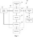
- FIG. 7is a schematic overview of one embodiment of components of a stimulation system, including an electronic subassembly disposed within a control module, according to the invention.
- the present inventionis directed to the area of implantable electrical stimulation systems and methods of making and using the systems, and in particular implantable electrical stimulation leads having elongate anchoring elements and methods of making and using the leads.
- Suitable implantable electrical stimulation systemsinclude, but are not limited to, a least one lead with at least one electrode disposed along a distal end of the lead and at least one terminal disposed along the at least one proximal end of the lead.
- Leadsinclude, for example, percutaneous leads, paddle leads, and cuff leads. Examples of electrical stimulation systems with leads are found in, for example, U.S. Pat. Nos.
- 2007/01500362009/0187222; 2009/0276021; 2010/0076535; 2010/0268298; 2011/0005069; 2011/0004267; 2011/0078900; 2011/0130817; 2011/0130818; 2011/0238129; 2011/0313500; 2012/0016378; 2012/0046710; 2012/0071949; 2012/0165911; 2012/0197375; 2012/0203316; 2012/0203320; 2012/0203321; 2012/0316615; 2013/0105071; and 2013/0197602, all of which are incorporated by reference.
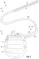
- FIG. 1illustrates schematically one embodiment of an electrical stimulation system 100 .
- the electrical stimulation systemincludes a control module (for example, a stimulator or pulse generator) 102 and a lead 103 coupleable to the control module 102 .
- the lead 103includes a paddle body 104 and at least one lead body 106 .
- the lead 103is shown having two lead bodies 106 .
- the lead 103can include any suitable number of lead bodies including, for example, one, two, three, four, five, six, seven, eight or more lead bodies 106 .
- An array 133 of electrodes, such as electrode 134is disposed on the paddle body 104
- an array of terminals(for example, 310 in FIG. 3A ) is disposed along each of the at least one lead body 106 . In at least some embodiments, there may be a single electrode 134 or a single terminal.
- the electrical stimulation systemcan include more, fewer, or different components and can have a variety of different configurations including those configurations disclosed in the electrical stimulation system references cited herein.
- the electrodesinstead of a paddle body, the electrodes can be disposed in an array at or near the distal end of a lead body forming a percutaneous lead.
- FIG. 2illustrates schematically another embodiment of the electrical stimulation system 100 , where the lead 103 is a percutaneous lead.
- the electrodes 134are shown disposed along the at least one lead body 106 .
- the lead 103is isodiametric along a longitudinal length of the lead body 106 .
- the lead 103can be coupled to the control module 102 in any suitable manner.
- the lead 103is shown coupling directly to the control module 102 .
- the lead 103couples to the control module 102 via at least one intermediate device ( 324 in FIG. 3B ).
- at least one lead extension 324can be disposed between the lead 103 and the control module 102 to extend the distance between the lead 103 and the control module 102 .
- Other intermediate devicesmay be used in addition to, or in lieu of, at least one lead extension including, for example, a splitter, an adaptor, or the like or combinations thereof. It will be understood that, in the case where the electrical stimulation system 100 includes multiple intermediate devices disposed between the lead 103 and the control module 102 , the intermediate devices may be configured into any suitable arrangement.
- the electrical stimulation system 100is shown having a splitter 107 configured and arranged for facilitating coupling of the lead 103 to the control module 102 .
- the splitter 107includes a splitter connector 108 configured to couple to a proximal end of the lead 103 , and at least one splitter tail 109 a and 109 b configured and arranged to couple to the control module 102 (or another splitter, a lead extension, an adaptor, or the like).
- the control module 102typically includes a connector housing 112 and a sealed electronics housing 114 .
- An electronic subassembly 110 and an optional power source 120are disposed in the electronics housing 114 .
- a control module connector 144is disposed in the connector housing 112 .
- the control module connector 144is configured and arranged to make an electrical connection between the lead 103 and the electronic subassembly 110 of the control module 102 .
- the electrical stimulation system 100 or components of the electrical stimulation system 100are typically implanted into the body of a patient.
- the electrical stimulation system 100can be used for a variety of applications including, but not limited to deep brain stimulation, neural stimulation, spinal cord stimulation, muscle stimulation, and the like.
- the electrodes 134can be formed using any conductive, biocompatible material. Examples of suitable materials include metals, alloys, conductive polymers, conductive carbon, and the like, as well as combinations thereof. In at least some embodiments, at least one of the electrodes 134 are formed from at least one of: platinum, platinum iridium, palladium, palladium rhodium, or titanium.
- Electrodes 134can be disposed on the lead 103 including, for example, one, two, three, four, five, six, seven, eight, nine, ten, eleven, twelve, fourteen, sixteen, twenty-four, thirty-two, or more electrodes 134 .
- the electrodes 134can be disposed on the paddle body 104 in any suitable arrangement. In FIG. 1 , the electrodes 134 are arranged into two columns, where each column has eight electrodes 134 .
- the electrodes 134 of the paddle body 104are typically disposed in, or separated by, a non-conductive, biocompatible material such as, for example, silicone, polyurethane, polyetheretherketone (“PEEK”), epoxy, and the like or combinations thereof.
- a non-conductive, biocompatible materialsuch as, for example, silicone, polyurethane, polyetheretherketone (“PEEK”), epoxy, and the like or combinations thereof.
- the at least one lead body 106 and, if applicable, the paddle body 104may be formed in the desired shape by any process including, for example, molding (including injection molding), casting, and the like.
- the non-conductive materialtypically extends from the distal ends of the at least one lead body 106 to the proximal end of each of the at least one lead body 106 .
- the non-conductive materialtypically extends from the paddle body 104 to the proximal end of each of the at least one lead body 106 .
- the non-conductive, biocompatible material of the paddle body 104 and the at least one lead body 106may be the same or different.
- the paddle body 104 and the at least one lead body 106may be a unitary structure or can be formed as two separate structures that are permanently or detachably coupled together.
- the electrically conductive wiresmay be embedded in the non-conductive material of the lead body 106 or can be disposed in at least one lumen (see, for example, FIGS. 4F and 4G ) extending along the lead body 106 .
- two or more conductorsextend through a lumen.
- At least one lumenmay open at, or near, the distal end of the at least one lead body 106 , for example, for infusion of drugs or medication into the site of implantation of the at least one lead body 106 .
- the at least one lumenare flushed continually, or on a regular basis, with saline, epidural fluid, or the like.
- the at least one lumenare permanently or removably sealable at the distal end.
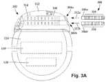
- FIG. 3Ais a schematic side view of one embodiment of a proximal end of at least one elongated device 300 configured and arranged for coupling to one embodiment of the control module connector 144 .
- the at least one elongated device 300may include, for example, at least one of the lead bodies 106 of FIG. 1 , at least one intermediate device (for example, a splitter, the lead extension 324 of FIG. 3B , an adaptor, or the like or combinations thereof), or a combination thereof.
- the control module connector 144defines at least one port into which a proximal end of the elongated device 300 can be inserted, as shown by directional arrows 312 a and 312 b .
- the connector housing 112is shown having two ports 304 a and 304 b .
- the connector housing 112can define any suitable number of ports including, for example, one, two, three, four, five, six, seven, eight, or more ports.
- FIG. 3Bis a schematic side view of another embodiment of the electrical stimulation system 100 .
- the electrical stimulation system 100includes a lead extension 324 that is configured and arranged to couple at least one elongated device 300 (for example, one of the lead bodies 106 of FIGS. 1 and 2 , the splitter 107 of FIG. 2 , an adaptor, another lead extension, or the like or combinations thereof) to the control module 102 .
- the lead extension 324is shown coupled to a single port 304 defined in the control module connector 144 .
- the lead extension 324is shown configured and arranged to couple to a single elongated device 300 .
- the lead extension 324is configured and arranged to couple to multiple ports 304 defined in the control module connector 144 , or to receive multiple elongated devices 300 , or both.
- a lead extension connector 322is disposed on the lead extension 324 .
- the lead extension connector 322is shown disposed at a distal end 326 of the lead extension 324 .
- the lead extension connector 322includes a connector housing 328 .
- the connector housing 328defines at least one port 330 into which terminals 310 of the elongated device 300 can be inserted, as shown by directional arrow 338 .
- the connector housing 328also includes a plurality of connector contacts, such as connector contacts 340 .
- the connector contacts 340 disposed in the connector housing 328can be aligned with the terminals 310 of the elongated device 300 to electrically couple the lead extension 324 to the electrodes ( 134 of FIGS. 1 and 2 ) disposed along the lead ( 103 in FIGS. 1 and 2 ).
- the proximal end 348 of the lead extension 324is configured and arranged for insertion into a connector disposed in another lead extension (or another intermediate device). In other embodiments (and as shown in FIG. 3B ), the proximal end 348 of the lead extension 324 is configured and arranged for insertion into the control module connector 144 .
- proximal and distalare used consistently with respect to all elements of the lead and system and are defined relative to the proximal end portion of the lead which attaches to the control module.
- the distal end portion of the leadhas the electrodes disposed thereon.
- Lead anchoring elementscan be attached to the lead to facilitate anchoring the lead into patient tissue.
- tissueincludes, but is not limited to, muscular tissue, connective tissue, organ tissue, bone, cartilage, nerve tissue, and the like.
- These lead anchoring elementscan be delivered with the lead through an introducer during the implantation process.
- the lead anchoring elementsextend into, and lodge against, patient tissue and prevent or reduce lateral or axial (or both lateral and axial) migration of the lead after implantation.
- the lead anchoring elementscan be particularly useful for leads for sacral nerve stimulation, spinal cord stimulation, or the stimulation of other patient tissue and organs.
- the anchoring elementsare discussed below for use with a lead, it will be understood that the same anchoring elements can be used with a lead extension.
- the corresponding element in a lead extensionwould be the connector or connector contacts of the lead extension.
- FIG. 4Aillustrates one embodiment of a portion of a lead 400 with a lead body 406 (illustrated as partially transparent to show the interior of the lead body 406 ) and anchoring elements 450 disposed in anchoring lumens 456 .
- the anchoring lumens 456extend inside the lead body 406 and each anchoring lumen includes at least one open slot 458 through the lead body to expose a portion of the anchoring lumen.
- Each anchoring element 450includes at least one bent portion 452 .
- the bent portion 452is biased to extend at least partially out of a slot 458 of the anchoring lumen 456 in which the anchoring element 458 resides (for example, extending at least 0.1, 0.2, 0.3, 0.4, or 0.5 mm from the lead body 406 ).
- Thisis a deployed position of the anchoring element 458 with an extension portion 454 disposed outside of the lead body 406 .
- each anchoring element 450may have multiple extension portions 454 that, in the deployed position, extend through multiple slots 458 (for example, longitudinally or circumferentially offset extension portions 454 and slots 458 ).
- Each of the anchoring elements 450has a thin, elongate structure and can be made of, for example, a conductive or non-conductive wire of any suitable length.
- the anchoring element 450is made of the same material as electrodes of the lead or can be made of a shape memory or superelastic material such as a Ni—Ti alloy (for example, NitinolTM), or any combination of those materials.
- the anchoring element 450is insulated with a covering or coating of at least one non-conductive material.
- anchoring elements 450can be any suitable number.
- a leadcan have 1, 2, 3, 4, 5, 6, 8, 10, 12, 14, 16, or more anchoring elements 450 (or extension portions 454 with fewer anchoring elements 450 ).
- each anchoring element 450is in a different anchoring lumen 456 , but, in other embodiments, two or more anchoring elements 450 can reside in the same anchoring lumen.
- Each extension portion 454may have the same or a different shape.
- each extension portion 454in the deployed position, may form two sides (with equal or different lengths) of a triangular shape.
- the distal side of the triangular shapeis longer than the proximal side.
- This triangular shapemay facilitate sliding an introducer over the lead body 406 (from the distal end toward the proximal end) and thereby pushing the anchoring element 450 into the constrained position. After implantation, this triangular shape may increase the amount of force necessary to move the lead body 406 relative to the surrounding tissue, especially in the direction where the short side of the triangle pushes against the tissue.
- the distal side of the triangular shapeis shorter, as illustrated in FIG. 4D .
- the extension portion 454forms an arc shape (for example, the arc may curve away from the lead body 406 , form an apex, then curve toward the lead body 406 ), as illustrated in FIG. 4E .
- Any other suitable shape of the extension portioncan be used.
- a leadcan include any combination of different shapes of the extension portions 454 of the anchoring elements 450 .
- a leadmay include one or more anchoring elements 450 with extension portions 454 having the shape illustrated in FIG. 4A and one or anchoring elements 450 with extension portions 454 having the shape illustrated in FIG. 4D . Any other combination of the shapes illustrated in FIGS. 4A-4E can be used.
- the extension portions 454are all proximal to the electrodes 434 . Other arrangements are possible including one or more extension portions 454 distal to one or more electrodes 434 , at least one extension portion 454 positioned laterally between electrodes 434 , or any combination thereof. In addition, in some embodiments, the extension portions 454 are nearer the electrodes than the terminals (see, for example, FIGS. 4D and 4E ). For example, in some embodiments, the extension portions may be disposed a distance away from the nearest electrode that is within 1, 2, 3, 4, or 5 times the spacing between adjacent electrodes. In some embodiments, the extension portions 454 may be nearer the terminals than the electrodes.
- FIG. 4F and FIG. 4Grespectively taken along lines 4 F- 4 F and 4 G- 4 G of FIG. 4A , show one embodiment of the lead body 406 , including a multi-lumen guide 460 that defines at least one anchoring lumen 456 and at least one conductor lumen 462 .
- each anchoring lumen 456carries at least one anchoring element 450
- each conductor lumen 462carries at least one conductor.
- a lumen 456 , 462includes both a conductor and an anchoring element 450 .
- an anchoring element 450 in an anchoring lumen 456is also a conductor that electrically couples a terminal to an electrode.
- the multi-lumen guide 460includes a central lumen 464 for a stylet or for passage of drugs or fluids to the treatment site.
- the lead body 406includes the multi-lumen guide 460 with a jacket (not shown) disposed over the multi-lumen guide, but also includes slots 458 through the corresponding sites on the jacket.
- the number of conductor lumens 462totals 1, 2, 3, 4, 5, 6, 8, 10, 12, 14, 16, or more lumens. In at least some embodiments, the number of anchoring lumens 456 totals 1, 2, 3, 4, 5, 6, 8, or more lumens.
- the number of conductor lumens 462may be equal to, fewer than, or more than the number of anchoring lumens 456 . In at least some embodiments, each pair of anchoring lumens 456 is separated by at least one conductor lumen 462 . In at least some embodiments, each anchoring lumen 456 is smaller than, larger than, or the same size as a conductor lumen 462 .
- the anchoring lumens 456(and thereby the anchoring elements 450 ) may be spaced apart from each other around the lead body 406 . In at least some embodiments, the anchoring lumens 456 may be non-uniformly or uniformly spaced apart from each other. In at least some embodiments, the anchoring lumens 456 may be spaced apart from each other by 60°, 90°, 120°, or 180° around the lead body 406 , or any combination thereof.
- the slots 458can be formed by any suitable method including, but not limited to, removing a portion of the multi-lumen guide 460 , as illustrated in FIG. 4G .
- the removal of material to form the slots 458can be performed by any suitable method including, but not limited to, ablation, cutting, grinding, or the like.
- FIG. 5Ais a perspective view of an attachment member 502 attached to the anchoring elements 450 (the attachment member 502 is illustrated as partially transparent to show attachment of the anchoring elements 450 ).
- the attachment member 502can have a ring shape or any other suitable shape.
- the attachment member 502may also be a marker band, retention sleeve, terminal, contact, or the like.
- the attachment member 502can be made of metal, plastic or any other suitable biocompatible material.
- the attachment member 502is attached to all of the anchoring elements 450 . In at least some other embodiments, the attachment member 502 is attached to less than all of the anchoring elements 450 , particularly if the lead includes at least two attachment members 502 .
- the attachment member 502is attached to the anchoring elements 450 by welding, soldering, brazing, adhesive, mechanical joints, or the like.
- the attachment member 502may be attached to the anchoring elements 450 prior or subsequent to the anchoring elements 502 being disposed in the anchoring lumens 456 .
- the anchoring elements 450may be shaped (for example, shaping the bent portion 452 or the extension portion 454 ) prior or subsequent to attaching the anchoring elements 450 to the attachment member 502 (and prior to or subsequent to being disposed in the anchoring lumens 456 ).
- the attached anchoring elements 450are disposed in the anchoring lumens 456 while the attachment member 502 is disposed along the lead body 406 .
- the attachment member 502may be disposed at any suitable position on the lead body 406 .
- the attachment member 502is disposed proximal to slots 458 (for example, at a position that, prior to explant of the lead, is more accessible than the distal end of the lead body 406 , such as proximal to a longitudinal mid-point of the lead).
- the proximal end portions of the anchoring elements 450terminate at the attachment member 502 .
- the anchoring lumen 456terminates at the attachment member 502 (proximal to the attachment member 502 or may extend proximal of the attachment member with the anchoring lumen 456 and, at least in some embodiments, this proximal portion being filled with polymer material prior to or after insertion of the anchoring element 450 into the anchoring lumen 456 ).
- the attachment member 502can be disposed on the lead body 406 using a method similar to disposition of the electrodes or terminals or can be disposed on the lead by sliding onto the lead, swaging, adhesive attachment, or the like.
- the attachment member 502can be used to pull the attached anchoring elements 450 into a restrained position, for example, as illustrated in FIG. 5C .
- the lead 400is prepared for explantation by cutting away the portion of the lead body proximal to the attachment member 502 so that the attachment member can be detached from the lead body 406 .
- the extension portions 454 in the restrained positionare proximal to the corresponding slots 458 .
- moving the attachment member 502 along the lead body 406retracts the anchoring elements 450 into the restrained position.
- Retracting the anchoring elements 450can be useful to reduce the overall diameter of the lead for explanting the lead.
- the attachment member 502can be moved to completely remove the anchoring elements 450 from the lead body 406 prior to explanting the lead.
- one or more of the anchoring elements 450can each be attached to an electrode 434 with a connection that is weaker than the attachment to the attachment member 502 . In this case, for example, when the attachment member 502 is pulled with sufficient force, the connection with the electrode 434 may break so that the anchoring members 502 can be removed from the lead. In at least some of these embodiments, one or more of the anchoring elements 450 can also act as a conductor electrically coupling a terminal to an electrode.
- the attachment member 502can be pulled by hand or with a tool, such as, for example, forceps, tweezers, or the like.
- a toolsuch as, for example, forceps, tweezers, or the like.
- the lead body 406can be cut near the attachment member 502 (for example, proximal to the attachment member 502 , such as along the proximal edge of the attachment member 502 ).
- FIG. 6Aillustrates one embodiment of a tool 600 that can be used to pull the attachment member 502 .
- the tool 600has two members 602 , 604 that pivot relative to each other about a hinge 606 (for example, a pivot hinge, spring hinge, or any other suitable hinge).
- a hinge 606for example, a pivot hinge, spring hinge, or any other suitable hinge.
- the hinged members 602 , 604form two apertures 608 , 610 or only one of the apertures 608 , 610 .
- Each of the apertures 608 , 610may have an inner diameter that is less than the outer diameter of the attachment member 502 to push or pull the attachment member when the aperture 608 or 610 is closed around and slid along the lead body 406 .
- the inner diametermay also be less than the outer diameter of the lead body 406 to compress the lead body 406 . Compressing the lead body 406 near the attachment member 502 (for example, distal or proximal, or both, to the attachment member 502 ) can be useful to reduce the amount of friction between the lead body 406 and the attachment member 502 .
- the inner diameters of the apertures 608 , 610are different sizes to accommodate different sizes of lead bodies or attachment members.
- the tool 600includes gripping members 612 a , 612 b (for example, finger rings, finger tangs, cross-hatched or serrated surfaces, or any other suitable gripping members or any combination thereof).
- the gripping members 612 a , 612 bmay be opposite the hinge 606 from the apertures 608 , 610 (for example, when employing a pivot hinge) or may be on the same side as the apertures 608 , 610 (for example, when employing a spring hinge).
- the hinged members 602 , 604terminate at or about the hinge 606 .
- the hinged members 602 , 604are biased to the open or closed position (for example, biased by a spring, elastic band, or the like). In other embodiments, the hinged members are not biased to either position.
- the tool 600may be locking or non-locking.
- the hinged members 602 , 604may each include interlocking teeth that engage each other in the closed position.
- the tool 600may be made of plastic, rubber, metal, or any other suitable material or any combination thereof.
- FIG. 6Bis a close-up view of the apertures 608 , 610 .
- at least one of the apertures 608 , 610has at least one counterbore that slidingly catches the attachment member 502 while the aperture 608 or 610 compresses the lead body 406 (for example, as shown in FIG. 6D ).
- at least one of the apertures 606 , 608has two opposing counterbores (for example, as shown in FIG. 6D ), one to pull the attachment member 502 and another to push the attachment member 502 .
- the inner diameter of each counterboremay be larger than the outer diameter of the attachment member 502 .
- at least one of the apertures 608 , 610may include a countersink.
- one hinged member 602may define a first portion of each aperture 608 a , 610 a while the other hinged member 604 defines a second portion of each aperture 608 b , 610 b . At least one of the first portions 608 a , 610 a may be symmetrical or asymmetrical to the corresponding second portion 608 b or 610 b .
- the aperture 608permits sliding the attachment member 502 parallel to the longitudinal axis of the tool 600 (as shown in FIG. 6D ), whereas the aperture 610 permits sliding the attachment member 502 perpendicular to the longitudinal axis of the tool 600 .
- the attachment member 502When the attachment member 502 is engaged by the tool 600 , the attachment member 502 can be pulled away from a remainder of the lead to separate the attachment member 502 and attachment elements 450 from the lead. This then retractions the extension portions 454 into (and optionally out of the lead) so that they no longer engage tissue and allow the lead to be more easily explanted. It will be understood that other tools, such as forceps or specially-designed tools, can be used to pull the attachment member 502 and attachment elements 450 away from the lead to facilitate explantation of the lead.
- FIG. 7is a schematic overview of one embodiment of components of an electrical stimulation system 700 including an electronic subassembly 710 disposed within a control module. It will be understood that the electrical stimulation system can include more, fewer, or different components and can have a variety of different configurations including those configurations disclosed in the stimulator references cited herein.
- a power source 712can be used including, for example, a battery such as a primary battery or a rechargeable battery.
- a batterysuch as a primary battery or a rechargeable battery.
- other power sourcesinclude super capacitors, nuclear or atomic batteries, mechanical resonators, infrared collectors, thermally-powered energy sources, flexural powered energy sources, bioenergy power sources, fuel cells, bioelectric cells, osmotic pressure pumps, and the like including the power sources described in U.S. Pat. No. 7,437,193, incorporated herein by reference.
- powercan be supplied by an external power source through inductive coupling via the optional antenna 718 or a secondary antenna.
- the external power sourcecan be in a device that is mounted on the skin of the user or in a unit that is provided near the user on a permanent or periodic basis.
- the batterymay be recharged using the optional antenna 718 , if desired. Power can be provided to the battery for recharging by inductively coupling the battery through the antenna to a recharging unit 716 external to the user. Examples of such arrangements can be found in the references identified above.
- Any processorcan be used and can be as simple as an electronic device that, for example, produces pulses at a regular interval or the processor can be capable of receiving and interpreting instructions from an external programming unit 708 that, for example, allows modification of pulse characteristics.
- the processor 704is coupled to a receiver 702 which, in turn, is coupled to the optional antenna 718 . This allows the processor 704 to receive instructions from an external source to, for example, direct the pulse characteristics and the selection of electrodes, if desired.
- the programming unit 708can be part of the telemetry unit 706 or can provide signals or information to the telemetry unit 706 via a wireless or wired connection.
- One example of a suitable programming unitis a computer operated by the user or clinician to send signals to the telemetry unit 706 .
- the signals sent to the processor 704 via the antenna 718 and the receiver 702can be used to modify or otherwise direct the operation of the electrical stimulation system.
- the signalsmay be used to modify the pulses of the electrical stimulation system such as modifying at least one of pulse duration, pulse frequency, pulse waveform, and pulse strength.
- the signalsmay also direct the electrical stimulation system 700 to cease operation, to start operation, to start charging the battery, or to stop charging the battery.
- the stimulation systemdoes not include the antenna 718 or receiver 702 and the processor 704 operates as programmed.
Landscapes
- Health & Medical Sciences (AREA)
- Heart & Thoracic Surgery (AREA)
- Cardiology (AREA)
- Animal Behavior & Ethology (AREA)
- Public Health (AREA)
- Nuclear Medicine, Radiotherapy & Molecular Imaging (AREA)
- Radiology & Medical Imaging (AREA)
- Life Sciences & Earth Sciences (AREA)
- Engineering & Computer Science (AREA)
- General Health & Medical Sciences (AREA)
- Biomedical Technology (AREA)
- Veterinary Medicine (AREA)
- Neurology (AREA)
- Neurosurgery (AREA)
- Orthopedic Medicine & Surgery (AREA)
- Vascular Medicine (AREA)
- Electrotherapy Devices (AREA)
Abstract
Description
Claims (19)
Priority Applications (1)
| Application Number | Priority Date | Filing Date | Title |
|---|---|---|---|
| US15/905,398US10709886B2 (en) | 2017-02-28 | 2018-02-26 | Electrical stimulation leads and systems with elongate anchoring elements and methods of making and using |
Applications Claiming Priority (2)
| Application Number | Priority Date | Filing Date | Title |
|---|---|---|---|
| US201762464902P | 2017-02-28 | 2017-02-28 | |
| US15/905,398US10709886B2 (en) | 2017-02-28 | 2018-02-26 | Electrical stimulation leads and systems with elongate anchoring elements and methods of making and using |
Publications (2)
| Publication Number | Publication Date |
|---|---|
| US20180243551A1 US20180243551A1 (en) | 2018-08-30 |
| US10709886B2true US10709886B2 (en) | 2020-07-14 |
Family
ID=63245281
Family Applications (1)
| Application Number | Title | Priority Date | Filing Date |
|---|---|---|---|
| US15/905,398Active2038-08-12US10709886B2 (en) | 2017-02-28 | 2018-02-26 | Electrical stimulation leads and systems with elongate anchoring elements and methods of making and using |
Country Status (1)
| Country | Link |
|---|---|
| US (1) | US10709886B2 (en) |
Cited By (4)
| Publication number | Priority date | Publication date | Assignee | Title |
|---|---|---|---|---|
| US20220142542A1 (en)* | 2020-11-06 | 2022-05-12 | Greatbatch Ltd. | Method of conductor management within a medical device |
| US12357792B2 (en) | 2019-01-04 | 2025-07-15 | Shifamed Holdings, Llc | Internal recharging systems and methods of use |
| US12403315B2 (en) | 2021-04-27 | 2025-09-02 | Boston Scientific Neuromodulation Corporation | Systems and methods for automated programming of electrical stimulation |
| US12440656B2 (en) | 2021-04-23 | 2025-10-14 | Shifamed Holdings, Llc | Power management for interatrial shunts and associated systems and methods |
Families Citing this family (3)
| Publication number | Priority date | Publication date | Assignee | Title |
|---|---|---|---|---|
| JP7729779B2 (en)* | 2019-03-26 | 2025-08-26 | パズル メディカル デバイシズ インコーポレイテッド | Modular mammalian body implantable fluid flow affecting device and related methods |
| US12383723B2 (en) | 2019-10-05 | 2025-08-12 | Puzzle Medical Devices Inc. | Mammalian body implantable fluid flow influencing device |
| WO2024092349A1 (en) | 2022-11-01 | 2024-05-10 | Puzzle Medical Devices Inc. | Implantable medical devices and related methods thereof |
Citations (249)
| Publication number | Priority date | Publication date | Assignee | Title |
|---|---|---|---|---|
| US376810A (en) | 1888-01-24 | Tug-hook | ||
| US612685A (en) | 1898-10-18 | Coupling for broom-handles | ||
| US2046837A (en) | 1934-07-03 | 1936-07-07 | Phillips Screw Co | Means for uniting a screw with a driver |
| US3333045A (en) | 1965-07-20 | 1967-07-25 | Gen Electric | Body implantable electrical conductor |
| US3866615A (en) | 1973-01-15 | 1975-02-18 | Daigle Claude W | Portable electronic cardiac stimulator |
| US3918440A (en) | 1973-03-09 | 1975-11-11 | Werner Kraus | Device for promoting formation of bone material |
| US4141752A (en) | 1977-07-21 | 1979-02-27 | Coratomic, Inc. | Organ-stimulating apparatus and insulating set screw for such apparatus |
| US4276882A (en) | 1979-05-18 | 1981-07-07 | Medtronic, Inc. | Lead anchoring device |
| US4316471A (en) | 1980-05-19 | 1982-02-23 | Coratomic, Inc. | Organ stimulating apparatus with sealing setscrew |
| EP0085417A1 (en) | 1982-01-29 | 1983-08-10 | Medtronic, Inc. | Biomedical stimulation lead |
| US4462401A (en) | 1982-11-15 | 1984-07-31 | Minnesota Mining And Manufacturing Company | Method and anchor for anchoring electrode leads used in cochlear implantation |
| US4632670A (en) | 1985-04-04 | 1986-12-30 | Argon Medical Corp. | Suture tab |
| US4764132A (en) | 1986-03-28 | 1988-08-16 | Siemens-Pacesetter, Inc. | Pacemaker connector block for proximal ring electrode |
| US4858623A (en) | 1987-07-13 | 1989-08-22 | Intermedics, Inc. | Active fixation mechanism for lead assembly of an implantable cardiac stimulator |
| US5036862A (en) | 1987-04-06 | 1991-08-06 | Cordis Corporation | Implantable, self-retaining lead |
| US5107856A (en) | 1991-01-10 | 1992-04-28 | Siemens-Pacesetter, Inc. | Multiple lead suture sleeve |
| US5143090A (en) | 1989-11-02 | 1992-09-01 | Possis Medical, Inc. | Cardiac lead |
| US5158097A (en) | 1990-06-08 | 1992-10-27 | Allegheny-Singer Research Institute | Paraneural stimulating lead |
| US5217028A (en) | 1989-11-02 | 1993-06-08 | Possis Medical, Inc. | Bipolar cardiac lead with drug eluting device |
| US5228248A (en) | 1992-07-13 | 1993-07-20 | Haddock Robert M M | Mounting device for building structures |
| US5269809A (en) | 1990-07-02 | 1993-12-14 | American Cyanamid Company | Locking mechanism for use with a slotted suture anchor |
| EP0597213A1 (en) | 1992-11-02 | 1994-05-18 | Medtronic, Inc. | Suture sleeve with lead locking device |
| US5330477A (en) | 1992-01-28 | 1994-07-19 | Amei Technologies Inc. | Apparatus and method for bone fixation and fusion stimulation |
| US5370662A (en) | 1993-06-23 | 1994-12-06 | Kevin R. Stone | Suture anchor assembly |
| US5376108A (en) | 1993-05-20 | 1994-12-27 | Telectronics Pacing Systems, Inc. | Electrode lead anchoring apparatus and method employing dual suture collars |
| JPH0714681A (en) | 1993-06-25 | 1995-01-17 | Matsushita Electric Works Ltd | lighting equipment |
| US5484445A (en) | 1993-10-12 | 1996-01-16 | Medtronic, Inc. | Sacral lead anchoring system |
| US5584874A (en) | 1995-04-28 | 1996-12-17 | Medtronic, Inc. | Medical electrical lead having improved anchoring sleeve |
| US5628780A (en) | 1993-06-17 | 1997-05-13 | Pacesetter, Inc. | Protective, visible suture sleeve for anchoring transvenous lead bodies |
| US5738521A (en) | 1996-07-19 | 1998-04-14 | Biolectron, Inc. | Method for accelerating osseointegration of metal bone implants using electrical stimulation |
| US5746722A (en) | 1997-02-05 | 1998-05-05 | Medtronic, Inc. | Suture sleeve with circumferential lead locking device |
| US5865843A (en) | 1997-04-23 | 1999-02-02 | Medtronic Inc. | Medical neurological lead with integral fixation mechanism |
| US5876431A (en) | 1997-07-30 | 1999-03-02 | Sulzer Intermedics Inc. | Small cable endocardial lead with exposed guide tube |
| US5895360A (en) | 1996-06-26 | 1999-04-20 | Medtronic, Inc. | Gain control for a periodic signal and method regarding same |
| US5957968A (en) | 1997-09-26 | 1999-09-28 | Medtronic, Inc. | Suture sleeve with lead locking device |
| WO1999053994A1 (en) | 1998-04-20 | 1999-10-28 | Medtronic, Inc. | Medical leads with enhanced biocompatibility and biostability |
| WO2000013743A1 (en) | 1998-09-03 | 2000-03-16 | Surgical Navigation Technologies, Inc. | Anchoring system for a brain lead |
| US6104957A (en) | 1998-08-21 | 2000-08-15 | Alo; Kenneth M. | Epidural nerve root stimulation with lead placement method |
| WO2000064535A1 (en) | 1999-04-26 | 2000-11-02 | Advanced Neuromodulation Systems, Inc. | Lead connector |
| US6175710B1 (en) | 1991-07-06 | 2001-01-16 | Fujitsu Limited | Electrophotographic recording apparatus using developing device with one-component type developer and having combination of charge injection effect and conductive contact type charger |
| US6181969B1 (en) | 1998-06-26 | 2001-01-30 | Advanced Bionics Corporation | Programmable current output stimulus stage for implantable device |
| US6192279B1 (en) | 1999-02-23 | 2001-02-20 | Medtronic, Inc. | Non-invasively maneuverable lead system |
| US20010000187A1 (en) | 2000-10-23 | 2001-04-05 | Case Western Reserve University | Functional neuromuscular stimulation system |
| US6224450B1 (en) | 1998-08-28 | 2001-05-01 | Laurie J. Norton | Cycling activity belt |
| US6271094B1 (en) | 2000-02-14 | 2001-08-07 | International Business Machines Corporation | Method of making MOSFET with high dielectric constant gate insulator and minimum overlap capacitance |
| US6295944B1 (en) | 2000-06-20 | 2001-10-02 | J Timothy Lovett | Automatic tethering system for a floating dock |
| JP2001339829A (en) | 2000-05-30 | 2001-12-07 | Lec Inc | Cord stop |
| US6360750B1 (en) | 1999-04-29 | 2002-03-26 | Medtronic, Inc. | Minimally invasive surgical techniques for implanting devices that deliver stimulant to the nervous system |
| US6364278B1 (en) | 1999-11-05 | 2002-04-02 | Hon Hai Precision Ind. Co., Ltd. | Stand for supporting a computer |
| US6391985B1 (en) | 1999-10-21 | 2002-05-21 | Union Carbide Chemicals & Plastics Technology Corporation | High condensing mode polyolefin production under turbulent conditions in a fluidized bed |
| US20020107554A1 (en) | 2001-02-08 | 2002-08-08 | Biggs James C. | One piece header assembly for an implantable medical device |
| US6473654B1 (en) | 2000-03-08 | 2002-10-29 | Advanced Bionics Corporation | Lead anchor |
| US6506190B1 (en) | 1998-05-21 | 2003-01-14 | Christopher J. Walshe | Tissue anchor system |
| US6516227B1 (en) | 1999-07-27 | 2003-02-04 | Advanced Bionics Corporation | Rechargeable spinal cord stimulator system |
| WO2003020365A1 (en) | 2001-08-31 | 2003-03-13 | Medtronic, Inc. | Method and apparatus for fixation of an implantable stimulation lead |
| US20030074023A1 (en) | 2001-06-29 | 2003-04-17 | Andrew Kaplan | Suture method |
| US20030078623A1 (en) | 2001-10-22 | 2003-04-24 | Weinberg Lisa P. | Implantable lead and method for stimulating the vagus nerve |
| US6606523B1 (en) | 1999-04-14 | 2003-08-12 | Transneuronix Inc. | Gastric stimulator apparatus and method for installing |
| US6609032B1 (en) | 1999-01-07 | 2003-08-19 | Advanced Bionics Corporation | Fitting process for a neural stimulation system |
| US6609029B1 (en) | 2000-02-04 | 2003-08-19 | Advanced Bionics Corporation | Clip lock mechanism for retaining lead |
| WO2003084398A1 (en) | 2002-04-04 | 2003-10-16 | Alfred E. Mann Foundation For Scientific Research | Electrically sensing and stimulating system for placement of a nerve stimulator or sensor |
| US20030208247A1 (en) | 2001-09-28 | 2003-11-06 | Michele Spinelli | Implantable stimulation lead with tissue in-growth anchor |
| US20040059392A1 (en) | 2002-06-28 | 2004-03-25 | Jordi Parramon | Microstimulator having self-contained power source |
| US6741892B1 (en) | 2000-03-10 | 2004-05-25 | Advanced Bionics Corporation | Movable contact locking mechanism for spinal cord stimulator lead connector |
| WO2004054655A1 (en) | 2002-12-13 | 2004-07-01 | Advanced Neuromodulation Systems, Inc. | System and method for electrical stimulation of the intervertebral disc |
| US6792314B2 (en) | 2001-06-18 | 2004-09-14 | Alfred E. Mann Foundation For Scientific Research | Miniature implantable array and stimulation system suitable for eyelid stimulation |
| US6847849B2 (en) | 2000-11-15 | 2005-01-25 | Medtronic, Inc. | Minimally invasive apparatus for implanting a sacral stimulation lead |
| US20050033393A1 (en) | 2003-08-08 | 2005-02-10 | Advanced Neuromodulation Systems, Inc. | Apparatus and method for implanting an electrical stimulation system and a paddle style electrical stimulation lead |
| US20050033374A1 (en) | 2002-09-06 | 2005-02-10 | Medtronic, Inc. | Method, system and device for treating disorders of the pelvic floor by electrical stimulation of and the delivery of drugs to various nerves or tissues |
| US6901287B2 (en) | 2001-02-09 | 2005-05-31 | Medtronic, Inc. | Implantable therapy delivery element adjustable anchor |
| US6902547B2 (en) | 2001-08-02 | 2005-06-07 | Teodulo Aves | Medical needle |
| US20050165465A1 (en) | 2002-01-29 | 2005-07-28 | Pianca Anne M. | Lead assembly for implantable microstimulator |
| US6978180B2 (en) | 2003-01-03 | 2005-12-20 | Advanced Neuromodulation Systems, Inc. | System and method for stimulation of a person's brain stem |
| US20050283202A1 (en) | 2004-06-22 | 2005-12-22 | Gellman Barry N | Neuromodulation system |
| WO2005120203A2 (en) | 2004-06-07 | 2005-12-22 | Synthes (U.S.A.) | Orthopaedic implant with sensors |
| US20050288760A1 (en) | 2004-05-04 | 2005-12-29 | Andre Machado | Corpus callosum neuromodulation assembly |
| US6984145B1 (en) | 2004-04-16 | 2006-01-10 | Pacesetter, Inc. | Implantable medical device connector assembly with side-actuated lead body affixation |
| WO2006029257A2 (en) | 2004-09-08 | 2006-03-16 | Spinal Modulation Inc. | Neurostimulation methods and systems |
| US20060127158A1 (en) | 2004-10-21 | 2006-06-15 | Medtronic, Inc. | Implantable electrical lead retention system and method |
| US7072719B2 (en) | 2001-09-20 | 2006-07-04 | Medtronic, Inc. | Implantable percutaneous stimulation lead with interlocking elements |
| US20060161235A1 (en) | 2005-01-19 | 2006-07-20 | Medtronic, Inc. | Multiple lead stimulation system and method |
| US20060173520A1 (en) | 2005-01-07 | 2006-08-03 | Medtronic, Inc. | Implantable retention system and method |
| WO2006086363A2 (en) | 2005-02-07 | 2006-08-17 | Warsaw Orthopedic, Inc. | Apparatus and method for locating defects in bone tissue |
| US20060205995A1 (en) | 2000-10-12 | 2006-09-14 | Gyne Ideas Limited | Apparatus and method for treating female urinary incontinence |
| US20060206162A1 (en) | 2005-03-11 | 2006-09-14 | Wahlstrand Carl D | Implantable neurostimulator device |
| US7161461B1 (en) | 2006-03-07 | 2007-01-09 | Delphi Technologies, Inc. | Injection molded trim resistor assembly |
| US20070010794A1 (en) | 2002-11-01 | 2007-01-11 | Mitchell Dann | Devices and methods for endolumenal gastrointestinal bypass |
| US7184841B1 (en) | 2004-08-19 | 2007-02-27 | Cardiac Pacemakers, Inc. | Pacing lead stabilizer |
| US20070050005A1 (en) | 2005-08-26 | 2007-03-01 | Advanced Bionics Corporation | Lead anchor for implantable stimulation devices and methods of manufacture and use |
| US20070078399A1 (en) | 2005-03-07 | 2007-04-05 | Medtronic, Inc. | Medical device anchor and method of manufacture thereof |
| US7203548B2 (en) | 2002-06-20 | 2007-04-10 | Advanced Bionics Corporation | Cavernous nerve stimulation via unidirectional propagation of action potentials |
| WO2007041604A2 (en) | 2005-10-03 | 2007-04-12 | Washington University | Electrode for stimulating bone growth, tissue healing and/or pain control, and method of use |
| US20070100348A1 (en) | 1999-10-20 | 2007-05-03 | Cauthen Joseph C Iii | Apparatus and methods for the treatment of the intervertebral disc |
| US20070112385A1 (en) | 2005-11-15 | 2007-05-17 | Conlon Sean P | Expandable suture anchor |
| WO2007056384A2 (en) | 2005-11-07 | 2007-05-18 | The Board Of Regents Of The University Of Texas System | Mesh anchoring system |
| US7235078B2 (en) | 2002-11-26 | 2007-06-26 | Hs West Investments Llc | Protective devices for use with angled interference screws |
| US20070150036A1 (en) | 2005-12-27 | 2007-06-28 | Advanced Bionics Corporation | Stimulator leads and methods for lead fabrication |
| US7244150B1 (en) | 2006-01-09 | 2007-07-17 | Advanced Bionics Corporation | Connector and methods of fabrication |
| WO2007083108A2 (en) | 2006-01-18 | 2007-07-26 | Algotec Limited | Implantable elongate member |
| US20070219595A1 (en) | 2006-03-14 | 2007-09-20 | Advanced Bionics Corporation | Stimulator system with electrode array and the method of making the same |
| US20070239248A1 (en) | 2006-03-31 | 2007-10-11 | Hastings Roger N | Cardiac stimulation electrodes, delivery devices, and implantation configurations |
| US20070255369A1 (en) | 2006-04-28 | 2007-11-01 | Bonde Eric H | Multi-electrode peripheral nerve evaluation lead and related system and method of use |
| US20070265682A1 (en) | 2006-05-12 | 2007-11-15 | Stryker Trauma Gmbh | Bone stimulation system |
| WO2007149994A2 (en) | 2006-06-21 | 2007-12-27 | Intrapace, Inc. | Endoscopic device delivery system |
| WO2008009789A1 (en) | 2006-07-21 | 2008-01-24 | Valeo Systemes De Controle Moteur | Combustion engine supply circuit with swirling of the gases and corresponding combustion engine |
| US7343202B2 (en) | 2004-02-12 | 2008-03-11 | Ndi Medical, Llc. | Method for affecting urinary function with electrode implantation in adipose tissue |
| US20080071320A1 (en) | 2006-09-18 | 2008-03-20 | Advanced Bionics Corporation | Feed through interconnect assembly for an implantable stimulation system and methods of making and using |
| US20080091255A1 (en) | 2006-10-11 | 2008-04-17 | Cardiac Pacemakers | Implantable neurostimulator for modulating cardiovascular function |
| US20080140153A1 (en) | 2006-12-06 | 2008-06-12 | Spinal Modulation, Inc. | Expandable stimulation leads and methods of use |
| US20080140169A1 (en) | 2006-12-06 | 2008-06-12 | Spinal Modulation, Inc. | Delivery devices, systems and methods for stimulating nerve tissue on multiple spinal levels |
| US20080140130A1 (en) | 2004-01-26 | 2008-06-12 | Chan Jason S | Highly-versatile variable-angle bone plate system |
| US20080140152A1 (en) | 2006-12-06 | 2008-06-12 | Spinal Modulation, Inc. | Implantable flexible circuit leads and methods of use |
| US20080172116A1 (en) | 2007-01-16 | 2008-07-17 | Ndi Medical, Inc. | Devices, systems, and methods employing a molded nerve cuff electrode |
| US7402076B1 (en) | 2006-10-26 | 2008-07-22 | Pacesetter, Inc. | Retaining mechanism for an implantable medical device connector assembly |
| US20080183241A1 (en) | 2006-07-31 | 2008-07-31 | Cranial Medical Systems, Inc. | Multi-channel connector for brain stimulation system |
| US20080183253A1 (en) | 2007-01-30 | 2008-07-31 | Cardiac Pacemakers, Inc. | Neurostimulating lead having a stent-like anchor |
| US20080196939A1 (en) | 2007-02-15 | 2008-08-21 | Advanced Bionics Corporation | Lead anchoring assembly |
| US20080228251A1 (en) | 2005-08-24 | 2008-09-18 | Rolf Hill | Suture Sleeve |
| US20080243220A1 (en) | 2007-03-28 | 2008-10-02 | Advanced Bionics Corporation | Lead anchor for implantable stimulation devices |
| US20080262588A1 (en) | 2004-08-16 | 2008-10-23 | Cardiac Pacemakers, Inc. | Lead assembly and methods including a push tube |
| US20080275401A1 (en) | 2007-05-01 | 2008-11-06 | Sage Shahn S | Catheter anchor and system/method regarding same |
| US7450997B1 (en) | 2000-12-29 | 2008-11-11 | Boston Scientific Neuromodulation Corporation | Method of implanting a lead for brain stimulation |
| US20080312712A1 (en) | 2007-06-13 | 2008-12-18 | E-Pacing, Inc. | Implantable Devices and Methods for Stimulation of Cardiac or Other Tissues |
| US20090018601A1 (en) | 2007-07-12 | 2009-01-15 | Medtronic, Inc. | Connector header for implantable medical device |
| US20090112272A1 (en) | 2007-10-31 | 2009-04-30 | Boston Scientific Neuromodulation Corporation | Connector assemblies for implantable stimulators |
| US20090187222A1 (en) | 2008-01-23 | 2009-07-23 | Boston Scientific Neuromodulation Corporation | Steerable stylet handle assembly |
| US20090198312A1 (en) | 2008-01-31 | 2009-08-06 | John Michael Barker | Lead with lead stiffener for implantable electrical stimulation systems and methods of making and using |
| US20090204193A1 (en) | 2008-02-12 | 2009-08-13 | Intelect Medical, Inc. | Directional lead assembly |
| US20090210043A1 (en) | 2008-02-15 | 2009-08-20 | Reddy G Shantanu | Medical electrical lead with proximal armoring |
| US7596414B2 (en) | 2005-12-05 | 2009-09-29 | Boston Scientific Neuromodulation Corporation | Cuff electrode arrangement for nerve stimulation and methods of treating disorders |
| US20090248095A1 (en) | 2008-04-01 | 2009-10-01 | Boston Scientific Neuromodulation Corporation | Anchoring units for leads of implantable electric stimulation systems and methods of making and using |
| US20090254151A1 (en) | 2008-04-02 | 2009-10-08 | Boston Scientific Neuromodulation Corporation | Lead anchor for implantable devices and methods of manufacture and use |
| US20090259260A1 (en) | 1999-10-20 | 2009-10-15 | Anulex Technologies, Inc. | Method and apparatus for the treatment of the intervertebral disc annulus |
| US7610102B2 (en) | 2007-10-25 | 2009-10-27 | Kowalczyk James M | Strain relief system for spinal cord stimulation lead |
| US7610103B2 (en) | 2005-12-19 | 2009-10-27 | Boston Scientific Neuromodulation Corporation | Electrode arrangement for nerve stimulation and methods of treating disorders |
| US20090270940A1 (en) | 2008-04-23 | 2009-10-29 | Medtronic, Inc. | Lead retention assembly for implantable medical device |
| US20090276021A1 (en) | 2008-04-30 | 2009-11-05 | Boston Scientific Neuromodulation Corporation | Electrodes for stimulation leads and methods of manufacture and use |
| US20090276025A1 (en) | 2008-04-30 | 2009-11-05 | Medtronic, Inc. | Techniques for placing medical leads for electrical stimulation of nerve tissue |
| US20090281571A1 (en) | 2008-05-08 | 2009-11-12 | Aesculap Implant Systems, Inc. | Minimally invasive spinal stabilization system |
| US7672734B2 (en) | 2005-12-27 | 2010-03-02 | Boston Scientific Neuromodulation Corporation | Non-linear electrode array |
| US20100076535A1 (en) | 2008-09-25 | 2010-03-25 | Boston Scientific Neuromodulation Corporation | Leads with non-circular-shaped distal ends for brain stimulation systems and methods of making and using |
| US20100094425A1 (en) | 2008-10-14 | 2010-04-15 | Anulex Technologies, Inc. | Method and apparatus for the treatment of the intervertebral disc annulus |
| US20100137938A1 (en) | 2008-10-27 | 2010-06-03 | Eyad Kishawi | Selective stimulation systems and signal parameters for medical conditions |
| US20100174240A1 (en) | 2009-01-06 | 2010-07-08 | Medtronic, Inc. | Anchor having fill port for use with an implantable therapy delivery element |
| US20100179562A1 (en) | 2009-01-14 | 2010-07-15 | Linker Fred I | Stimulation leads, delivery systems and methods of use |
| US7761165B1 (en) | 2005-09-29 | 2010-07-20 | Boston Scientific Neuromodulation Corporation | Implantable stimulator with integrated plastic housing/metal contacts and manufacture and use |
| US7783359B2 (en) | 2005-01-05 | 2010-08-24 | Boston Scientific Neuromodulation Corporation | Devices and methods using an implantable pulse generator for brain stimulation |
| US20100241179A1 (en) | 1998-04-30 | 2010-09-23 | Medtronic, Inc. | Techniques for Positioning Therapy Delivery Elements within a Spinal Cord or Brain |
| US20100249875A1 (en) | 2009-03-24 | 2010-09-30 | Eyad Kishawi | Pain management with stimulation subthreshold to paresthesia |
| US7809446B2 (en) | 2005-01-05 | 2010-10-05 | Boston Scientific Neuromodulation Corporation | Devices and methods for brain stimulation |
| US20100268298A1 (en) | 2009-04-16 | 2010-10-21 | Boston Scientific Neuromodulation Corporation | Deep brain stimulation current steering with split electrodes |
| US20100274336A1 (en) | 2009-04-27 | 2010-10-28 | Boston Scientific Neuromodulation Corporation | Torque lock anchor and methods and devices using the anchor |
| US20100286670A1 (en) | 2004-06-16 | 2010-11-11 | Mark Doyle | Surgical tool kit |
| US7848803B1 (en) | 2005-03-14 | 2010-12-07 | Boston Scientific Neuromodulation Corporation | Methods and systems for facilitating stimulation of one or more stimulation sites |
| US20100312319A1 (en) | 2009-06-04 | 2010-12-09 | Boston Scientific Neuromodulation Corporation | Three-piece button anchor and methods and devices using the anchor |
| US7853321B2 (en) | 2005-03-14 | 2010-12-14 | Boston Scientific Neuromodulation Corporation | Stimulation of a stimulation site within the neck or head |
| US20110005069A1 (en) | 2009-07-07 | 2011-01-13 | Boston Scientific Neuromodulation Corporation | Systems and leads with a radially segmented electrode array and methods of manufacture |
| US20110022066A1 (en) | 2008-03-26 | 2011-01-27 | Synthes Usa, Llc | Universal anchor for attaching objects to bone tissue |
| US20110022142A1 (en) | 2009-07-21 | 2011-01-27 | Boston Scientific Neuromdoulation Corporation | Tubular lead anchor and methods and devices using the anchor |
| US20110060395A1 (en) | 2009-09-09 | 2011-03-10 | Kurt Cantlon | Key locking anchoring device for implanted lead |
| US20110078900A1 (en) | 2009-07-07 | 2011-04-07 | Boston Scientific Neuromodulation Corporation | Methods for making leads with radially-aligned segmented electrodes for electrical stimulation systems |
| US7949395B2 (en) | 1999-10-01 | 2011-05-24 | Boston Scientific Neuromodulation Corporation | Implantable microdevice with extended lead and remote electrode |
| US20110130817A1 (en) | 2009-11-30 | 2011-06-02 | Boston Scientific Neuromodulation Corporation | Electrode array having a rail system and methods of manufacturing the same |
| US20110130818A1 (en) | 2009-11-30 | 2011-06-02 | Boston Scientific Neuromodulation Corporation | Electrode array having concentric split ring electrodes and methods of making the same |
| US20110130803A1 (en) | 2009-11-30 | 2011-06-02 | Boston Scientific Neuromodulation Corporation | Electrode array having concentric windowed cylinder electrodes and methods of making the same |
| US20110130816A1 (en) | 2009-11-30 | 2011-06-02 | Boston Scientific Neuromodulation Corporation | Electrode array with electrodes having cutout portions and methods of making the same |
| US7974706B2 (en) | 2006-03-30 | 2011-07-05 | Boston Scientific Neuromodulation Corporation | Electrode contact configurations for cuff leads |
| US20110178573A1 (en) | 2009-04-27 | 2011-07-21 | Boston Scientific Neuromodulation Corporation | Torque lock anchor and methods and devices using the anchor |
| US7993378B2 (en) | 1996-03-22 | 2011-08-09 | Warsaw Orthopedic, IN. | Methods for percutaneous spinal surgery |
| US20110213445A1 (en) | 2007-02-05 | 2011-09-01 | Brian Blischak | Stimulation lead, stimulation system, and method for limiting mri-induced current in a stimulation lead |
| US20110238129A1 (en) | 2010-03-23 | 2011-09-29 | Boston Scientific Neuromodulation Corporation | Helical radial spacing of contacts on a cylindrical lead |
| US20110264180A1 (en) | 2010-04-27 | 2011-10-27 | Hamilton Dennison R | Spinal cord stimulator lead anchor |
| US20110276056A1 (en) | 2010-05-10 | 2011-11-10 | Grigsby Eric J | Methods, systems and devices for reducing migration |
| US20110313500A1 (en) | 2010-06-18 | 2011-12-22 | Boston Scientific Neuromodulation Corporation | Electrode array having embedded electrodes and methods of making the same |
| US20110313427A1 (en) | 2007-07-10 | 2011-12-22 | Gindele Paul J | Deployable electrode lead anchor |
| US20120016378A1 (en) | 2010-07-16 | 2012-01-19 | Boston Scientific Neuromodulation Corporation | Systems and methods for radial steering of electrode arrays |
| US20120046710A1 (en) | 2010-08-18 | 2012-02-23 | Boston Scientific Neuromodulation Corporation | Methods, systems, and devices for deep brain stimulation using helical movement of the centroid of stimulation |
| US20120071949A1 (en) | 2010-09-21 | 2012-03-22 | Boston Scientific Neuromodulation Corporation | Systems and methods for making and using radially-aligned segmented electrodes for leads of electrical stimulation systems |
| AU2012201634A1 (en) | 2004-09-08 | 2012-04-05 | Spinal Modulation Inc. | Neurostimulation methods and systems |
| US20120101326A1 (en) | 2009-03-20 | 2012-04-26 | ElectroCore, LLC. | Non-invasive electrical and magnetic nerve stimulators used to treat overactive bladder and urinary incontinence |
| US20120150202A1 (en) | 2010-12-14 | 2012-06-14 | Boston Scientific Neuromodulation Corporation | Devices containing a suture sleeve and methods of making and using |
| US20120165911A1 (en) | 2010-12-23 | 2012-06-28 | Boston Scientific Neuromodulation Corporation | Methods for making leads with segmented electrodes for electrical stimulation systems |
| US20120185027A1 (en) | 2009-04-27 | 2012-07-19 | Boston Scientific Neuromodulation Corporation | Torque lock anchor and methods and devices using the anchor |
| US8229573B2 (en) | 2009-07-21 | 2012-07-24 | Boston Scientific Neuromodulation Corporation | Spring passive lead anchor and methods and devices using the anchor |
| US20120197375A1 (en) | 2011-02-02 | 2012-08-02 | Boston Scientific Neuromodulation Corporation | Leads with spiral of helical segmented electrode arrays and methods of making and using the leads |
| US20120203320A1 (en) | 2011-02-08 | 2012-08-09 | Boston Scientific Neuromodulation Corporation | Leads with spirally arranged segmented electrodes and methods of making and using the leads |
| US20120203321A1 (en) | 2011-02-08 | 2012-08-09 | Boston Scientific Neuromodulation Corporation | Methods for making leads with segmented electrodes for electrical stimulation systems |
| US20120203316A1 (en) | 2011-02-08 | 2012-08-09 | Boston Scientific Neuromodulation Corporation | Leads with segmented electrodes for electrical stimulation of planar regions and methods of making and using |
| US20120232626A1 (en) | 2011-03-11 | 2012-09-13 | Greatbatch Ltd. | Anchor sleeve for implantable lead |
| US8271094B1 (en) | 2005-09-30 | 2012-09-18 | Boston Scientific Neuromodulation Corporation | Devices with cannula and electrode lead for brain stimulation and methods of use and manufacture |
| US20120277670A1 (en) | 2011-04-29 | 2012-11-01 | Medtronic, Inc. | Burr hole cap assembly with therapy delivery member orientation feature |
| US20120283835A1 (en) | 2011-05-03 | 2012-11-08 | Anulex Technologies, Inc. | Tissue fixation and repair systems and methods |
| US20120316615A1 (en) | 2011-06-07 | 2012-12-13 | Boston Scientific Neuromodulation Corporation | Systems and methods for making and using improved leads for electrical stimulation systems |
| US20120316627A1 (en)* | 2011-06-09 | 2012-12-13 | Ams Research Corporation | Electrode lead including a deployable tissue anchor |
| US20120323253A1 (en)* | 2010-09-28 | 2012-12-20 | Ellis Garai | Device and method for positioning an electrode in tissue |
| US20120330355A1 (en) | 2011-06-21 | 2012-12-27 | Greatbatch Ltd | Multi-durometer reinforced suture sleeve |
| US20130096659A1 (en) | 2011-10-13 | 2013-04-18 | Boston Scientific Neuromodulation Corporation | Systems and methods for anchoring leads of electrical stimulation systems |
| US20130105071A1 (en) | 2011-11-02 | 2013-05-02 | Boston Scientific Neuromodulation Corporation | Systems and methods for making and using improved leads for electrical stimulation systems |
| US20130149031A1 (en) | 2011-09-21 | 2013-06-13 | Bal Seal Engineering, Inc. | Multi-latching mechanisms and related methods |
| US8483237B2 (en) | 2008-05-28 | 2013-07-09 | Schneider Electric Automation Gmbh | Communication module and method for connecting an electrical device to a network |
| US20130197424A1 (en) | 2006-07-31 | 2013-08-01 | Cranial Medical Systems, Inc. | Lead and methods for brain monitoring and modulation |
| US20130197602A1 (en) | 2012-01-26 | 2013-08-01 | Boston Scientific Neuromodulation Corporation | Systems and methods for identifying the circumferential positioning of electrodes of leads for electrical stimulation systems |
| WO2013112920A1 (en) | 2012-01-25 | 2013-08-01 | Nevro Corporation | Lead anchors and associated systems and methods |
| US20130238023A1 (en) | 2012-03-07 | 2013-09-12 | Boston Scientific Neuromodulation Corporation | System and method for securing an implant to tissue |
| US20130261684A1 (en) | 2012-03-30 | 2013-10-03 | Boston Scientific Neuromodulation Corporation | Leads with x-ray fluorescent capsules for electrode identification and methods of manufacture and use |
| US8568462B2 (en) | 2007-11-02 | 2013-10-29 | Biomet C.V. | Bone plate system with two different types of drill guides |
| US20130317587A1 (en) | 2012-05-25 | 2013-11-28 | Boston Scientific Neuromodulation Corporation | Methods for stimulating the dorsal root ganglion with a lead having segmented electrodes |
| US20130317518A1 (en) | 2012-05-25 | 2013-11-28 | Boston Scientific Neuromodulation Corporation | Systems and methods for implanting an electrical stimulation lead using a sheath |
| US20130317583A1 (en) | 2012-05-25 | 2013-11-28 | Boston Scientific Neuromodulation Corporation | Percutaneous implantation of an electrical stimulation lead for stimulating dorsal root ganglion |
| US20130317586A1 (en) | 2012-05-25 | 2013-11-28 | Boston Scientific Neuromodulation Corporation | Systems and methods for providing electrical stimulation of multiple dorsal root ganglia with a single lead |
| US20130317588A1 (en) | 2012-05-25 | 2013-11-28 | Boston Scientific Neuromodulation Corporation | Distally curved electrical stimulation lead and methods of making and using |
| US20130325091A1 (en) | 2012-06-01 | 2013-12-05 | Boston Scientific Neuromodulation Corporation | Leads with tip electrode for electrical stimulation systems and methods of making and using |
| US20140018885A1 (en) | 2012-07-12 | 2014-01-16 | Boston Scientific Neuromodulation Corporation | Systems and methods for making and using an electrical stimulation system with a tissue-penetrating electrode |
| US20140039587A1 (en) | 2012-08-03 | 2014-02-06 | Boston Scientific Neuromodulation Corporation | Leads with electrode carrier for segmented electrodes and methods of making and using |
| US8647346B2 (en) | 2004-10-15 | 2014-02-11 | Baxano Surgical, Inc. | Devices and methods for tissue modification |
| US20140074093A9 (en) | 2005-05-18 | 2014-03-13 | Sonoma Orthopedic Products, Inc. | Straight intramedullary fracture fixation devices and methods |
| US8688235B1 (en) | 2008-07-22 | 2014-04-01 | Boston Scientific Neuromodulation Corporation | Lead with transition and methods of manufacture and use |
| US8768488B2 (en) | 2012-05-25 | 2014-07-01 | Boston Scientific Neuromodulation Corporation | Systems and methods for electrically stimulating patient tissue on or around one or more bony structures |
| US8774926B2 (en) | 2007-11-05 | 2014-07-08 | Nevro Corporation | Multi-frequency neural treatments and associated systems and methods |
| US8781603B2 (en) | 2008-07-21 | 2014-07-15 | Greatbatch Ltd. | Minimally invasive methods for implanting a sacral stimulation lead |
| US20140257240A1 (en) | 2013-03-08 | 2014-09-11 | Spinal Modulation, Inc. | Articulable introducer sheath |
| US20140276925A1 (en) | 2013-03-12 | 2014-09-18 | Spinal Modulation, Inc. | Methods and systems for use in guiding implantation of a neuromodulation lead |
| US20140343645A1 (en) | 2013-05-14 | 2014-11-20 | Boston Scientific Neuromodulation Corporation | Electrical stimulation leads and systems with anchoring units and methods of making and using |
| US20140343647A1 (en) | 2013-05-15 | 2014-11-20 | Boston Scientific Neuromodulation Corporation | Systems and methods for making and using tip electrodes for leads of electrical stimulation systems |
| US20140358209A1 (en) | 2013-05-31 | 2014-12-04 | Boston Scientific Neuromodulation Corporation | Leads with segmented electrodes and methods of making and using the leads |
| US20140358210A1 (en) | 2013-05-31 | 2014-12-04 | Boston Scientific Neuromodulation Corporation | Methods for manufacturing segmented electrode leads using a removable ring and the leads formed thereby |
| US20140353001A1 (en) | 2013-05-31 | 2014-12-04 | Boston Scientific Neuromodulation Corporation | Leads containing segmented electrodes with non-perpendicular legs and methods of making and using |
| US20140358207A1 (en) | 2013-05-31 | 2014-12-04 | Boston Scientific Neuromodulation Corporation | Segmented electrode leads formed from pre-electrodes with depressions or apertures and methods of making and using |
| US20150005856A1 (en) | 2013-06-27 | 2015-01-01 | Boston Scientific Neuromodulation Corporation | Lead anchors and systems and methods using the lead anchors |
| US20150018915A1 (en) | 2013-07-12 | 2015-01-15 | Boston Scientific Neuromodulation Corporation | Leads with segmented electrodes and methods of making and using the leads |
| US20150021817A1 (en) | 2013-07-22 | 2015-01-22 | Boston Scientific Neuromodulation Corporation | Molded segmented electrode leads and systems and methods of manufacturing and using the leads and systems |
| US20150045865A1 (en) | 2013-08-07 | 2015-02-12 | Boston Scientific Neuromodulation Corporation | Systems and methods for making and using lead anchors for leads of electrical stimulation systems |
| US20150045864A1 (en) | 2013-08-07 | 2015-02-12 | Boston Scientific Neuromodulation Corporation | Systems and methods for making and using segmented tip electrodes for leads of electrical stimulation systems |
| US20150051675A1 (en) | 2013-08-19 | 2015-02-19 | Boston Scientific Neuromodulation Corporation | Lead anchor with adhesive and systems and methods using the lead anchor |
| US20150051674A1 (en) | 2013-08-19 | 2015-02-19 | Boston Scientific Neuromodulation Corporation | Lead anchors and systems and methods employing the lead anchors |
| US20150066120A1 (en) | 2013-08-30 | 2015-03-05 | Boston Scientific Neuromodulation Corporation | Methods of making segmented electrode leads using flanged carrier |
| US20150066121A1 (en) | 2013-08-30 | 2015-03-05 | Boston Scientific Neuromodulation Corporation | Systems and methods for making and using lead anchors for leads of electrical stimulation systems |
| US20150099936A1 (en) | 2013-10-09 | 2015-04-09 | Spinal Modulation, Inc. | Sheath support devices, systems and methods |
| US20150134038A1 (en)* | 2013-11-08 | 2015-05-14 | Greatbatch Ltd. | Implantable medical lead with collapsible fixation member |
| US20150151113A1 (en) | 2013-12-02 | 2015-06-04 | Boston Scientific Neuromodulation Corporation | Electrical stimulation leads with helically arranged electrodes and methods of making and using |
| US20150246216A1 (en) | 2014-02-28 | 2015-09-03 | Boston Scientific Neuromodulation Corporation | Side loading lead anchor and methods of making and using thereof |
| US9138574B2 (en) | 2013-06-26 | 2015-09-22 | Medtronic, Inc. | Anchor deployment for implantable medical devices |
| US20150343198A1 (en) | 2014-05-27 | 2015-12-03 | Boston Scientific Neuromodulation Corporation | Systems and methods for making and using reversible mechanical lead anchors for electrical stimulation systems |
| US9259569B2 (en) | 2009-05-15 | 2016-02-16 | Daniel M. Brounstein | Methods, systems and devices for neuromodulating spinal anatomy |
| US20170036013A1 (en) | 2015-08-03 | 2017-02-09 | Boston Scientific Neuromodulation Corporation | Lead anchor with a wedge and systems using the lead anchor |
| US20170202616A1 (en)* | 2016-01-15 | 2017-07-20 | Tva Medical, Inc. | Devices and methods for forming a fistula |
| US20170246454A1 (en) | 2016-02-29 | 2017-08-31 | Boston Scientific Neuromodulation Corporation | Lead anchor for an electrical stimulation system |
| US20170333702A1 (en) | 2016-05-17 | 2017-11-23 | Boston Scientific Neuromodulation Corporation | Systems and method for anchoring a lead for neurostimulation of a target anatomy |
| US20180021569A1 (en) | 2016-07-25 | 2018-01-25 | Boston Scientific Neuromodulation Corporation | Systems and methods for making and using an electrical stimulation system for stimulation of dorsal root ganglia |
- 2018
- 2018-02-26USUS15/905,398patent/US10709886B2/enactiveActive
Patent Citations (296)
| Publication number | Priority date | Publication date | Assignee | Title |
|---|---|---|---|---|
| US376810A (en) | 1888-01-24 | Tug-hook | ||
| US612685A (en) | 1898-10-18 | Coupling for broom-handles | ||
| US2046837A (en) | 1934-07-03 | 1936-07-07 | Phillips Screw Co | Means for uniting a screw with a driver |
| US3333045A (en) | 1965-07-20 | 1967-07-25 | Gen Electric | Body implantable electrical conductor |
| US3866615A (en) | 1973-01-15 | 1975-02-18 | Daigle Claude W | Portable electronic cardiac stimulator |
| US3918440A (en) | 1973-03-09 | 1975-11-11 | Werner Kraus | Device for promoting formation of bone material |
| US4141752A (en) | 1977-07-21 | 1979-02-27 | Coratomic, Inc. | Organ-stimulating apparatus and insulating set screw for such apparatus |
| US4276882A (en) | 1979-05-18 | 1981-07-07 | Medtronic, Inc. | Lead anchoring device |
| US4316471A (en) | 1980-05-19 | 1982-02-23 | Coratomic, Inc. | Organ stimulating apparatus with sealing setscrew |
| EP0085417A1 (en) | 1982-01-29 | 1983-08-10 | Medtronic, Inc. | Biomedical stimulation lead |
| US4462401A (en) | 1982-11-15 | 1984-07-31 | Minnesota Mining And Manufacturing Company | Method and anchor for anchoring electrode leads used in cochlear implantation |
| US4632670A (en) | 1985-04-04 | 1986-12-30 | Argon Medical Corp. | Suture tab |
| US4764132A (en) | 1986-03-28 | 1988-08-16 | Siemens-Pacesetter, Inc. | Pacemaker connector block for proximal ring electrode |
| US5036862A (en) | 1987-04-06 | 1991-08-06 | Cordis Corporation | Implantable, self-retaining lead |
| US4858623A (en) | 1987-07-13 | 1989-08-22 | Intermedics, Inc. | Active fixation mechanism for lead assembly of an implantable cardiac stimulator |
| US5217028A (en) | 1989-11-02 | 1993-06-08 | Possis Medical, Inc. | Bipolar cardiac lead with drug eluting device |
| US5143090A (en) | 1989-11-02 | 1992-09-01 | Possis Medical, Inc. | Cardiac lead |
| US5158097A (en) | 1990-06-08 | 1992-10-27 | Allegheny-Singer Research Institute | Paraneural stimulating lead |
| US5269809A (en) | 1990-07-02 | 1993-12-14 | American Cyanamid Company | Locking mechanism for use with a slotted suture anchor |
| US5107856A (en) | 1991-01-10 | 1992-04-28 | Siemens-Pacesetter, Inc. | Multiple lead suture sleeve |
| US6175710B1 (en) | 1991-07-06 | 2001-01-16 | Fujitsu Limited | Electrophotographic recording apparatus using developing device with one-component type developer and having combination of charge injection effect and conductive contact type charger |
| US5330477A (en) | 1992-01-28 | 1994-07-19 | Amei Technologies Inc. | Apparatus and method for bone fixation and fusion stimulation |
| US5228248A (en) | 1992-07-13 | 1993-07-20 | Haddock Robert M M | Mounting device for building structures |
| EP0597213A1 (en) | 1992-11-02 | 1994-05-18 | Medtronic, Inc. | Suture sleeve with lead locking device |
| US5376108A (en) | 1993-05-20 | 1994-12-27 | Telectronics Pacing Systems, Inc. | Electrode lead anchoring apparatus and method employing dual suture collars |
| US5628780A (en) | 1993-06-17 | 1997-05-13 | Pacesetter, Inc. | Protective, visible suture sleeve for anchoring transvenous lead bodies |
| US5370662A (en) | 1993-06-23 | 1994-12-06 | Kevin R. Stone | Suture anchor assembly |
| JPH0714681A (en) | 1993-06-25 | 1995-01-17 | Matsushita Electric Works Ltd | lighting equipment |
| US5484445A (en) | 1993-10-12 | 1996-01-16 | Medtronic, Inc. | Sacral lead anchoring system |
| US5584874A (en) | 1995-04-28 | 1996-12-17 | Medtronic, Inc. | Medical electrical lead having improved anchoring sleeve |
| US7993378B2 (en) | 1996-03-22 | 2011-08-09 | Warsaw Orthopedic, IN. | Methods for percutaneous spinal surgery |
| US5895360A (en) | 1996-06-26 | 1999-04-20 | Medtronic, Inc. | Gain control for a periodic signal and method regarding same |
| US5738521A (en) | 1996-07-19 | 1998-04-14 | Biolectron, Inc. | Method for accelerating osseointegration of metal bone implants using electrical stimulation |
| US5746722A (en) | 1997-02-05 | 1998-05-05 | Medtronic, Inc. | Suture sleeve with circumferential lead locking device |
| WO1998033551A1 (en) | 1997-02-05 | 1998-08-06 | Medtronic, Inc. | Suture sleeve with circumferential lead locking device |
| US5865843A (en) | 1997-04-23 | 1999-02-02 | Medtronic Inc. | Medical neurological lead with integral fixation mechanism |
| US5876431A (en) | 1997-07-30 | 1999-03-02 | Sulzer Intermedics Inc. | Small cable endocardial lead with exposed guide tube |
| US5957968A (en) | 1997-09-26 | 1999-09-28 | Medtronic, Inc. | Suture sleeve with lead locking device |
| WO1999053994A1 (en) | 1998-04-20 | 1999-10-28 | Medtronic, Inc. | Medical leads with enhanced biocompatibility and biostability |
| US20100241179A1 (en) | 1998-04-30 | 2010-09-23 | Medtronic, Inc. | Techniques for Positioning Therapy Delivery Elements within a Spinal Cord or Brain |
| US7056333B2 (en) | 1998-05-21 | 2006-06-06 | Walshe Christopher J | Tissue anchor system |
| US6506190B1 (en) | 1998-05-21 | 2003-01-14 | Christopher J. Walshe | Tissue anchor system |
| US6181969B1 (en) | 1998-06-26 | 2001-01-30 | Advanced Bionics Corporation | Programmable current output stimulus stage for implantable device |
| US6104957A (en) | 1998-08-21 | 2000-08-15 | Alo; Kenneth M. | Epidural nerve root stimulation with lead placement method |
| US6224450B1 (en) | 1998-08-28 | 2001-05-01 | Laurie J. Norton | Cycling activity belt |
| WO2000013743A1 (en) | 1998-09-03 | 2000-03-16 | Surgical Navigation Technologies, Inc. | Anchoring system for a brain lead |
| US6609032B1 (en) | 1999-01-07 | 2003-08-19 | Advanced Bionics Corporation | Fitting process for a neural stimulation system |
| US6192279B1 (en) | 1999-02-23 | 2001-02-20 | Medtronic, Inc. | Non-invasively maneuverable lead system |
| US6606523B1 (en) | 1999-04-14 | 2003-08-12 | Transneuronix Inc. | Gastric stimulator apparatus and method for installing |
| WO2000064535A1 (en) | 1999-04-26 | 2000-11-02 | Advanced Neuromodulation Systems, Inc. | Lead connector |
| US6360750B1 (en) | 1999-04-29 | 2002-03-26 | Medtronic, Inc. | Minimally invasive surgical techniques for implanting devices that deliver stimulant to the nervous system |
| US6516227B1 (en) | 1999-07-27 | 2003-02-04 | Advanced Bionics Corporation | Rechargeable spinal cord stimulator system |
| US7949395B2 (en) | 1999-10-01 | 2011-05-24 | Boston Scientific Neuromodulation Corporation | Implantable microdevice with extended lead and remote electrode |
| US20070100348A1 (en) | 1999-10-20 | 2007-05-03 | Cauthen Joseph C Iii | Apparatus and methods for the treatment of the intervertebral disc |
| US20090259260A1 (en) | 1999-10-20 | 2009-10-15 | Anulex Technologies, Inc. | Method and apparatus for the treatment of the intervertebral disc annulus |
| US6391985B1 (en) | 1999-10-21 | 2002-05-21 | Union Carbide Chemicals & Plastics Technology Corporation | High condensing mode polyolefin production under turbulent conditions in a fluidized bed |
| US6364278B1 (en) | 1999-11-05 | 2002-04-02 | Hon Hai Precision Ind. Co., Ltd. | Stand for supporting a computer |
| US6609029B1 (en) | 2000-02-04 | 2003-08-19 | Advanced Bionics Corporation | Clip lock mechanism for retaining lead |
| US6271094B1 (en) | 2000-02-14 | 2001-08-07 | International Business Machines Corporation | Method of making MOSFET with high dielectric constant gate insulator and minimum overlap capacitance |
| US6473654B1 (en) | 2000-03-08 | 2002-10-29 | Advanced Bionics Corporation | Lead anchor |
| US6741892B1 (en) | 2000-03-10 | 2004-05-25 | Advanced Bionics Corporation | Movable contact locking mechanism for spinal cord stimulator lead connector |
| JP2001339829A (en) | 2000-05-30 | 2001-12-07 | Lec Inc | Cord stop |
| US6295944B1 (en) | 2000-06-20 | 2001-10-02 | J Timothy Lovett | Automatic tethering system for a floating dock |
| US20060205995A1 (en) | 2000-10-12 | 2006-09-14 | Gyne Ideas Limited | Apparatus and method for treating female urinary incontinence |
| US20010000187A1 (en) | 2000-10-23 | 2001-04-05 | Case Western Reserve University | Functional neuromuscular stimulation system |
| US20050240238A1 (en) | 2000-11-15 | 2005-10-27 | Medtronic, Inc. | Minimally invasive apparatus for implanting a sacral stimulation lead |
| US6847849B2 (en) | 2000-11-15 | 2005-01-25 | Medtronic, Inc. | Minimally invasive apparatus for implanting a sacral stimulation lead |
| US7792590B1 (en) | 2000-12-29 | 2010-09-07 | Boston Scientific Neuromodulation Corporation | Implantable lead systems for brain stimulation |
| US7450997B1 (en) | 2000-12-29 | 2008-11-11 | Boston Scientific Neuromodulation Corporation | Method of implanting a lead for brain stimulation |
| US20020107554A1 (en) | 2001-02-08 | 2002-08-08 | Biggs James C. | One piece header assembly for an implantable medical device |
| US6901287B2 (en) | 2001-02-09 | 2005-05-31 | Medtronic, Inc. | Implantable therapy delivery element adjustable anchor |
| US6792314B2 (en) | 2001-06-18 | 2004-09-14 | Alfred E. Mann Foundation For Scientific Research | Miniature implantable array and stimulation system suitable for eyelid stimulation |
| US20030074023A1 (en) | 2001-06-29 | 2003-04-17 | Andrew Kaplan | Suture method |
| US6902547B2 (en) | 2001-08-02 | 2005-06-07 | Teodulo Aves | Medical needle |
| WO2003020365A1 (en) | 2001-08-31 | 2003-03-13 | Medtronic, Inc. | Method and apparatus for fixation of an implantable stimulation lead |
| US7072719B2 (en) | 2001-09-20 | 2006-07-04 | Medtronic, Inc. | Implantable percutaneous stimulation lead with interlocking elements |
| US20030208247A1 (en) | 2001-09-28 | 2003-11-06 | Michele Spinelli | Implantable stimulation lead with tissue in-growth anchor |
| US20030078623A1 (en) | 2001-10-22 | 2003-04-24 | Weinberg Lisa P. | Implantable lead and method for stimulating the vagus nerve |
| US8364278B2 (en) | 2002-01-29 | 2013-01-29 | Boston Scientific Neuromodulation Corporation | Lead assembly for implantable microstimulator |
| US20050165465A1 (en) | 2002-01-29 | 2005-07-28 | Pianca Anne M. | Lead assembly for implantable microstimulator |
| US8204595B2 (en) | 2002-01-29 | 2012-06-19 | Boston Scientific Neuromodulation Corporation | Lead assembly for implantable microstimulator |
| WO2003084398A1 (en) | 2002-04-04 | 2003-10-16 | Alfred E. Mann Foundation For Scientific Research | Electrically sensing and stimulating system for placement of a nerve stimulator or sensor |
| US7203548B2 (en) | 2002-06-20 | 2007-04-10 | Advanced Bionics Corporation | Cavernous nerve stimulation via unidirectional propagation of action potentials |
| US20040059392A1 (en) | 2002-06-28 | 2004-03-25 | Jordi Parramon | Microstimulator having self-contained power source |
| US7437193B2 (en) | 2002-06-28 | 2008-10-14 | Boston Scientific Neuromodulation Corporation | Microstimulator employing improved recharging reporting and telemetry techniques |
| US20050033374A1 (en) | 2002-09-06 | 2005-02-10 | Medtronic, Inc. | Method, system and device for treating disorders of the pelvic floor by electrical stimulation of and the delivery of drugs to various nerves or tissues |
| US20070010794A1 (en) | 2002-11-01 | 2007-01-11 | Mitchell Dann | Devices and methods for endolumenal gastrointestinal bypass |
| US7235078B2 (en) | 2002-11-26 | 2007-06-26 | Hs West Investments Llc | Protective devices for use with angled interference screws |
| US7069083B2 (en) | 2002-12-13 | 2006-06-27 | Advanced Neuromodulation Systems, Inc. | System and method for electrical stimulation of the intervertebral disc |
| WO2004054655A1 (en) | 2002-12-13 | 2004-07-01 | Advanced Neuromodulation Systems, Inc. | System and method for electrical stimulation of the intervertebral disc |
| US6978180B2 (en) | 2003-01-03 | 2005-12-20 | Advanced Neuromodulation Systems, Inc. | System and method for stimulation of a person's brain stem |
| US20050033393A1 (en) | 2003-08-08 | 2005-02-10 | Advanced Neuromodulation Systems, Inc. | Apparatus and method for implanting an electrical stimulation system and a paddle style electrical stimulation lead |
| US20080140130A1 (en) | 2004-01-26 | 2008-06-12 | Chan Jason S | Highly-versatile variable-angle bone plate system |
| US20140180345A1 (en) | 2004-01-26 | 2014-06-26 | Jason S. Chan | Highly-Versatile Variable-Angle Bone Plate System |
| US7343202B2 (en) | 2004-02-12 | 2008-03-11 | Ndi Medical, Llc. | Method for affecting urinary function with electrode implantation in adipose tissue |
| US6984145B1 (en) | 2004-04-16 | 2006-01-10 | Pacesetter, Inc. | Implantable medical device connector assembly with side-actuated lead body affixation |
| US20050288760A1 (en) | 2004-05-04 | 2005-12-29 | Andre Machado | Corpus callosum neuromodulation assembly |
| WO2005120203A2 (en) | 2004-06-07 | 2005-12-22 | Synthes (U.S.A.) | Orthopaedic implant with sensors |
| US20100286670A1 (en) | 2004-06-16 | 2010-11-11 | Mark Doyle | Surgical tool kit |
| US20050283202A1 (en) | 2004-06-22 | 2005-12-22 | Gellman Barry N | Neuromodulation system |
| US20080262588A1 (en) | 2004-08-16 | 2008-10-23 | Cardiac Pacemakers, Inc. | Lead assembly and methods including a push tube |
| US7184841B1 (en) | 2004-08-19 | 2007-02-27 | Cardiac Pacemakers, Inc. | Pacing lead stabilizer |
| US8712546B2 (en) | 2004-09-08 | 2014-04-29 | Spinal Modulation, Inc. | Neurostimulation system |
| US7502651B2 (en) | 2004-09-08 | 2009-03-10 | Spinal Modulation, Inc. | Methods for stimulating a dorsal root ganglion |
| US8082039B2 (en) | 2004-09-08 | 2011-12-20 | Spinal Modulation, Inc. | Stimulation systems |
| US7447546B2 (en) | 2004-09-08 | 2008-11-04 | Spinal Modulation, Inc. | Methods of neurostimulating targeted neural tissue |
| AU2012201634A1 (en) | 2004-09-08 | 2012-04-05 | Spinal Modulation Inc. | Neurostimulation methods and systems |
| US8229565B2 (en) | 2004-09-08 | 2012-07-24 | Spinal Modulation, Inc. | Methods for stimulating a dorsal root ganglion |
| US7450993B2 (en) | 2004-09-08 | 2008-11-11 | Spinal Modulation, Inc. | Methods for selective stimulation of a ganglion |
| US7337005B2 (en) | 2004-09-08 | 2008-02-26 | Spinal Modulations, Inc. | Methods for stimulating a nerve root ganglion |
| US7337006B2 (en) | 2004-09-08 | 2008-02-26 | Spinal Modulation, Inc. | Methods and systems for modulating neural tissue |
| WO2006029257A2 (en) | 2004-09-08 | 2006-03-16 | Spinal Modulation Inc. | Neurostimulation methods and systems |
| US9205259B2 (en) | 2004-09-08 | 2015-12-08 | The Board Of Trustees Of The Leland Stanford Junior University | Neurostimulation system |
| US9205260B2 (en) | 2004-09-08 | 2015-12-08 | The Board Of Trustees Of The Leland Stanford Junior University | Methods for stimulating a dorsal root ganglion |
| US7580753B2 (en) | 2004-09-08 | 2009-08-25 | Spinal Modulation, Inc. | Method and system for stimulating a dorsal root ganglion |
| US8647346B2 (en) | 2004-10-15 | 2014-02-11 | Baxano Surgical, Inc. | Devices and methods for tissue modification |
| US20060127158A1 (en) | 2004-10-21 | 2006-06-15 | Medtronic, Inc. | Implantable electrical lead retention system and method |
| US20110004267A1 (en) | 2005-01-05 | 2011-01-06 | Boston Scientific Neuromodulation Corporation | Devices and methods for brain stimulation |
| US7809446B2 (en) | 2005-01-05 | 2010-10-05 | Boston Scientific Neuromodulation Corporation | Devices and methods for brain stimulation |
| US7783359B2 (en) | 2005-01-05 | 2010-08-24 | Boston Scientific Neuromodulation Corporation | Devices and methods using an implantable pulse generator for brain stimulation |
| US20060173520A1 (en) | 2005-01-07 | 2006-08-03 | Medtronic, Inc. | Implantable retention system and method |
| US20060161235A1 (en) | 2005-01-19 | 2006-07-20 | Medtronic, Inc. | Multiple lead stimulation system and method |
| WO2006086363A2 (en) | 2005-02-07 | 2006-08-17 | Warsaw Orthopedic, Inc. | Apparatus and method for locating defects in bone tissue |
| US20070078399A1 (en) | 2005-03-07 | 2007-04-05 | Medtronic, Inc. | Medical device anchor and method of manufacture thereof |
| US20060206162A1 (en) | 2005-03-11 | 2006-09-14 | Wahlstrand Carl D | Implantable neurostimulator device |
| US7853321B2 (en) | 2005-03-14 | 2010-12-14 | Boston Scientific Neuromodulation Corporation | Stimulation of a stimulation site within the neck or head |
| US8315704B2 (en) | 2005-03-14 | 2012-11-20 | Boston Scientific Neuromodulation Corporation | Stimulation of a stimulation site within the neck or head |
| US7848803B1 (en) | 2005-03-14 | 2010-12-07 | Boston Scientific Neuromodulation Corporation | Methods and systems for facilitating stimulation of one or more stimulation sites |
| US8224451B2 (en) | 2005-03-14 | 2012-07-17 | Boston Scientific Neuromodulation Corporation | Methods and systems for facilitating stimulation of one or more stimulation sites |
| US20140074093A9 (en) | 2005-05-18 | 2014-03-13 | Sonoma Orthopedic Products, Inc. | Straight intramedullary fracture fixation devices and methods |
| US20080228251A1 (en) | 2005-08-24 | 2008-09-18 | Rolf Hill | Suture Sleeve |
| US20070050005A1 (en) | 2005-08-26 | 2007-03-01 | Advanced Bionics Corporation | Lead anchor for implantable stimulation devices and methods of manufacture and use |
| US7761165B1 (en) | 2005-09-29 | 2010-07-20 | Boston Scientific Neuromodulation Corporation | Implantable stimulator with integrated plastic housing/metal contacts and manufacture and use |
| US8271094B1 (en) | 2005-09-30 | 2012-09-18 | Boston Scientific Neuromodulation Corporation | Devices with cannula and electrode lead for brain stimulation and methods of use and manufacture |
| WO2007041604A2 (en) | 2005-10-03 | 2007-04-12 | Washington University | Electrode for stimulating bone growth, tissue healing and/or pain control, and method of use |
| WO2007056384A2 (en) | 2005-11-07 | 2007-05-18 | The Board Of Regents Of The University Of Texas System | Mesh anchoring system |
| US20070112385A1 (en) | 2005-11-15 | 2007-05-17 | Conlon Sean P | Expandable suture anchor |
| US7596414B2 (en) | 2005-12-05 | 2009-09-29 | Boston Scientific Neuromodulation Corporation | Cuff electrode arrangement for nerve stimulation and methods of treating disorders |
| US7610103B2 (en) | 2005-12-19 | 2009-10-27 | Boston Scientific Neuromodulation Corporation | Electrode arrangement for nerve stimulation and methods of treating disorders |
| US20070150036A1 (en) | 2005-12-27 | 2007-06-28 | Advanced Bionics Corporation | Stimulator leads and methods for lead fabrication |
| US7672734B2 (en) | 2005-12-27 | 2010-03-02 | Boston Scientific Neuromodulation Corporation | Non-linear electrode array |
| US7244150B1 (en) | 2006-01-09 | 2007-07-17 | Advanced Bionics Corporation | Connector and methods of fabrication |
| WO2007083108A2 (en) | 2006-01-18 | 2007-07-26 | Algotec Limited | Implantable elongate member |
| US7161461B1 (en) | 2006-03-07 | 2007-01-09 | Delphi Technologies, Inc. | Injection molded trim resistor assembly |
| US20070219595A1 (en) | 2006-03-14 | 2007-09-20 | Advanced Bionics Corporation | Stimulator system with electrode array and the method of making the same |
| US8175710B2 (en) | 2006-03-14 | 2012-05-08 | Boston Scientific Neuromodulation Corporation | Stimulator system with electrode array and the method of making the same |
| US7974706B2 (en) | 2006-03-30 | 2011-07-05 | Boston Scientific Neuromodulation Corporation | Electrode contact configurations for cuff leads |
| US20070239248A1 (en) | 2006-03-31 | 2007-10-11 | Hastings Roger N | Cardiac stimulation electrodes, delivery devices, and implantation configurations |
| US20070255369A1 (en) | 2006-04-28 | 2007-11-01 | Bonde Eric H | Multi-electrode peripheral nerve evaluation lead and related system and method of use |
| US20070265682A1 (en) | 2006-05-12 | 2007-11-15 | Stryker Trauma Gmbh | Bone stimulation system |
| WO2007149994A2 (en) | 2006-06-21 | 2007-12-27 | Intrapace, Inc. | Endoscopic device delivery system |
| WO2008009789A1 (en) | 2006-07-21 | 2008-01-24 | Valeo Systemes De Controle Moteur | Combustion engine supply circuit with swirling of the gases and corresponding combustion engine |
| US20080183241A1 (en) | 2006-07-31 | 2008-07-31 | Cranial Medical Systems, Inc. | Multi-channel connector for brain stimulation system |
| US20130197424A1 (en) | 2006-07-31 | 2013-08-01 | Cranial Medical Systems, Inc. | Lead and methods for brain monitoring and modulation |
| US20080071320A1 (en) | 2006-09-18 | 2008-03-20 | Advanced Bionics Corporation | Feed through interconnect assembly for an implantable stimulation system and methods of making and using |
| US8224450B2 (en) | 2006-09-18 | 2012-07-17 | Boston Scientific Neuromodulation Corporation | Feed through interconnect assembly for an implantable stimulation system and methods of making and using |
| US20080091255A1 (en) | 2006-10-11 | 2008-04-17 | Cardiac Pacemakers | Implantable neurostimulator for modulating cardiovascular function |
| US7402076B1 (en) | 2006-10-26 | 2008-07-22 | Pacesetter, Inc. | Retaining mechanism for an implantable medical device connector assembly |
| US8983624B2 (en) | 2006-12-06 | 2015-03-17 | Spinal Modulation, Inc. | Delivery devices, systems and methods for stimulating nerve tissue on multiple spinal levels |
| US20080140153A1 (en) | 2006-12-06 | 2008-06-12 | Spinal Modulation, Inc. | Expandable stimulation leads and methods of use |
| US20080140169A1 (en) | 2006-12-06 | 2008-06-12 | Spinal Modulation, Inc. | Delivery devices, systems and methods for stimulating nerve tissue on multiple spinal levels |
| US20080140152A1 (en) | 2006-12-06 | 2008-06-12 | Spinal Modulation, Inc. | Implantable flexible circuit leads and methods of use |
| US20080172116A1 (en) | 2007-01-16 | 2008-07-17 | Ndi Medical, Inc. | Devices, systems, and methods employing a molded nerve cuff electrode |
| US20080183253A1 (en) | 2007-01-30 | 2008-07-31 | Cardiac Pacemakers, Inc. | Neurostimulating lead having a stent-like anchor |
| US20110213445A1 (en) | 2007-02-05 | 2011-09-01 | Brian Blischak | Stimulation lead, stimulation system, and method for limiting mri-induced current in a stimulation lead |
| US20080196939A1 (en) | 2007-02-15 | 2008-08-21 | Advanced Bionics Corporation | Lead anchoring assembly |
| WO2008101026A1 (en) | 2007-02-15 | 2008-08-21 | Boston Scientific Neuromodulation Corporation | Lead anchoring assembly |
| US7787960B2 (en) | 2007-02-15 | 2010-08-31 | Boston Scientific Neuromodulation Corporation | Lead anchoring assembly |
| WO2008121708A2 (en) | 2007-03-28 | 2008-10-09 | Boston Scientific Neuromodulation Corp. | Lead anchor for implantable stimulation devices |
| US20080243220A1 (en) | 2007-03-28 | 2008-10-02 | Advanced Bionics Corporation | Lead anchor for implantable stimulation devices |
| US20080275401A1 (en) | 2007-05-01 | 2008-11-06 | Sage Shahn S | Catheter anchor and system/method regarding same |
| US20080312712A1 (en) | 2007-06-13 | 2008-12-18 | E-Pacing, Inc. | Implantable Devices and Methods for Stimulation of Cardiac or Other Tissues |
| US20110313427A1 (en) | 2007-07-10 | 2011-12-22 | Gindele Paul J | Deployable electrode lead anchor |
| US20090018601A1 (en) | 2007-07-12 | 2009-01-15 | Medtronic, Inc. | Connector header for implantable medical device |
| US7610102B2 (en) | 2007-10-25 | 2009-10-27 | Kowalczyk James M | Strain relief system for spinal cord stimulation lead |
| US20090112272A1 (en) | 2007-10-31 | 2009-04-30 | Boston Scientific Neuromodulation Corporation | Connector assemblies for implantable stimulators |
| US8568462B2 (en) | 2007-11-02 | 2013-10-29 | Biomet C.V. | Bone plate system with two different types of drill guides |
| US8774926B2 (en) | 2007-11-05 | 2014-07-08 | Nevro Corporation | Multi-frequency neural treatments and associated systems and methods |
| US20090187222A1 (en) | 2008-01-23 | 2009-07-23 | Boston Scientific Neuromodulation Corporation | Steerable stylet handle assembly |
| US20090198312A1 (en) | 2008-01-31 | 2009-08-06 | John Michael Barker | Lead with lead stiffener for implantable electrical stimulation systems and methods of making and using |
| US20090204193A1 (en) | 2008-02-12 | 2009-08-13 | Intelect Medical, Inc. | Directional lead assembly |
| US20090210043A1 (en) | 2008-02-15 | 2009-08-20 | Reddy G Shantanu | Medical electrical lead with proximal armoring |
| US20110022066A1 (en) | 2008-03-26 | 2011-01-27 | Synthes Usa, Llc | Universal anchor for attaching objects to bone tissue |
| US20090248095A1 (en) | 2008-04-01 | 2009-10-01 | Boston Scientific Neuromodulation Corporation | Anchoring units for leads of implantable electric stimulation systems and methods of making and using |
| US8019443B2 (en) | 2008-04-01 | 2011-09-13 | Boston Scientific Neuromodulation Corporation | Anchoring units for leads of implantable electric stimulation systems and methods of making and using |
| US20090254151A1 (en) | 2008-04-02 | 2009-10-08 | Boston Scientific Neuromodulation Corporation | Lead anchor for implantable devices and methods of manufacture and use |
| US20090270940A1 (en) | 2008-04-23 | 2009-10-29 | Medtronic, Inc. | Lead retention assembly for implantable medical device |
| US7860568B2 (en) | 2008-04-23 | 2010-12-28 | Medtronic, Inc. | Lead retention assembly for implantable medical device |
| US20090276021A1 (en) | 2008-04-30 | 2009-11-05 | Boston Scientific Neuromodulation Corporation | Electrodes for stimulation leads and methods of manufacture and use |
| US20090276025A1 (en) | 2008-04-30 | 2009-11-05 | Medtronic, Inc. | Techniques for placing medical leads for electrical stimulation of nerve tissue |
| US20090281579A1 (en) | 2008-05-08 | 2009-11-12 | Aesculap Implant Systems, Inc. | Minimally invasive spinal stabilization system |
| US20090281571A1 (en) | 2008-05-08 | 2009-11-12 | Aesculap Implant Systems, Inc. | Minimally invasive spinal stabilization system |
| US20090281576A1 (en) | 2008-05-08 | 2009-11-12 | Aesculap Implant Systems, Inc. | Minimally invasive spinal stabilization system |
| US8483237B2 (en) | 2008-05-28 | 2013-07-09 | Schneider Electric Automation Gmbh | Communication module and method for connecting an electrical device to a network |
| US8781603B2 (en) | 2008-07-21 | 2014-07-15 | Greatbatch Ltd. | Minimally invasive methods for implanting a sacral stimulation lead |
| US8688235B1 (en) | 2008-07-22 | 2014-04-01 | Boston Scientific Neuromodulation Corporation | Lead with transition and methods of manufacture and use |
| US20100076535A1 (en) | 2008-09-25 | 2010-03-25 | Boston Scientific Neuromodulation Corporation | Leads with non-circular-shaped distal ends for brain stimulation systems and methods of making and using |
| US20100094425A1 (en) | 2008-10-14 | 2010-04-15 | Anulex Technologies, Inc. | Method and apparatus for the treatment of the intervertebral disc annulus |
| US20100137938A1 (en) | 2008-10-27 | 2010-06-03 | Eyad Kishawi | Selective stimulation systems and signal parameters for medical conditions |
| US20100174240A1 (en) | 2009-01-06 | 2010-07-08 | Medtronic, Inc. | Anchor having fill port for use with an implantable therapy delivery element |
| WO2010083308A1 (en) | 2009-01-14 | 2010-07-22 | Spinal Modulation, Inc. | Stimulation leads, delivery systems and methods of use |
| US20100179562A1 (en) | 2009-01-14 | 2010-07-15 | Linker Fred I | Stimulation leads, delivery systems and methods of use |
| US20120101326A1 (en) | 2009-03-20 | 2012-04-26 | ElectroCore, LLC. | Non-invasive electrical and magnetic nerve stimulators used to treat overactive bladder and urinary incontinence |
| US20100249875A1 (en) | 2009-03-24 | 2010-09-30 | Eyad Kishawi | Pain management with stimulation subthreshold to paresthesia |
| US20100268298A1 (en) | 2009-04-16 | 2010-10-21 | Boston Scientific Neuromodulation Corporation | Deep brain stimulation current steering with split electrodes |
| US20120185027A1 (en) | 2009-04-27 | 2012-07-19 | Boston Scientific Neuromodulation Corporation | Torque lock anchor and methods and devices using the anchor |
| US20110178573A1 (en) | 2009-04-27 | 2011-07-21 | Boston Scientific Neuromodulation Corporation | Torque lock anchor and methods and devices using the anchor |
| WO2010126853A1 (en) | 2009-04-27 | 2010-11-04 | Boston Scientific Neuromodulation Corporation | Torque lock anchor and methods and devices using the anchor |
| US20100274336A1 (en) | 2009-04-27 | 2010-10-28 | Boston Scientific Neuromodulation Corporation | Torque lock anchor and methods and devices using the anchor |
| US9259569B2 (en) | 2009-05-15 | 2016-02-16 | Daniel M. Brounstein | Methods, systems and devices for neuromodulating spinal anatomy |
| US20100312319A1 (en) | 2009-06-04 | 2010-12-09 | Boston Scientific Neuromodulation Corporation | Three-piece button anchor and methods and devices using the anchor |
| US20110078900A1 (en) | 2009-07-07 | 2011-04-07 | Boston Scientific Neuromodulation Corporation | Methods for making leads with radially-aligned segmented electrodes for electrical stimulation systems |
| US20110005069A1 (en) | 2009-07-07 | 2011-01-13 | Boston Scientific Neuromodulation Corporation | Systems and leads with a radially segmented electrode array and methods of manufacture |
| US8229573B2 (en) | 2009-07-21 | 2012-07-24 | Boston Scientific Neuromodulation Corporation | Spring passive lead anchor and methods and devices using the anchor |
| US20110022142A1 (en) | 2009-07-21 | 2011-01-27 | Boston Scientific Neuromdoulation Corporation | Tubular lead anchor and methods and devices using the anchor |
| US20110060395A1 (en) | 2009-09-09 | 2011-03-10 | Kurt Cantlon | Key locking anchoring device for implanted lead |
| US20110130816A1 (en) | 2009-11-30 | 2011-06-02 | Boston Scientific Neuromodulation Corporation | Electrode array with electrodes having cutout portions and methods of making the same |
| US8295944B2 (en) | 2009-11-30 | 2012-10-23 | Boston Scientific Neuromodulation Corporation | Electrode array with electrodes having cutout portions and methods of making the same |
| US20110130803A1 (en) | 2009-11-30 | 2011-06-02 | Boston Scientific Neuromodulation Corporation | Electrode array having concentric windowed cylinder electrodes and methods of making the same |
| US20110130818A1 (en) | 2009-11-30 | 2011-06-02 | Boston Scientific Neuromodulation Corporation | Electrode array having concentric split ring electrodes and methods of making the same |
| US20110130817A1 (en) | 2009-11-30 | 2011-06-02 | Boston Scientific Neuromodulation Corporation | Electrode array having a rail system and methods of manufacturing the same |
| US8391985B2 (en) | 2009-11-30 | 2013-03-05 | Boston Scientific Neuromodulation Corporation | Electrode array having concentric windowed cylinder electrodes and methods of making the same |
| US20110238129A1 (en) | 2010-03-23 | 2011-09-29 | Boston Scientific Neuromodulation Corporation | Helical radial spacing of contacts on a cylindrical lead |
| US20110264180A1 (en) | 2010-04-27 | 2011-10-27 | Hamilton Dennison R | Spinal cord stimulator lead anchor |
| US20110276056A1 (en) | 2010-05-10 | 2011-11-10 | Grigsby Eric J | Methods, systems and devices for reducing migration |
| US20110313500A1 (en) | 2010-06-18 | 2011-12-22 | Boston Scientific Neuromodulation Corporation | Electrode array having embedded electrodes and methods of making the same |
| US20120016378A1 (en) | 2010-07-16 | 2012-01-19 | Boston Scientific Neuromodulation Corporation | Systems and methods for radial steering of electrode arrays |
| US20120046710A1 (en) | 2010-08-18 | 2012-02-23 | Boston Scientific Neuromodulation Corporation | Methods, systems, and devices for deep brain stimulation using helical movement of the centroid of stimulation |
| US20120071949A1 (en) | 2010-09-21 | 2012-03-22 | Boston Scientific Neuromodulation Corporation | Systems and methods for making and using radially-aligned segmented electrodes for leads of electrical stimulation systems |
| US20120323253A1 (en)* | 2010-09-28 | 2012-12-20 | Ellis Garai | Device and method for positioning an electrode in tissue |
| US20120150202A1 (en) | 2010-12-14 | 2012-06-14 | Boston Scientific Neuromodulation Corporation | Devices containing a suture sleeve and methods of making and using |
| US20120165911A1 (en) | 2010-12-23 | 2012-06-28 | Boston Scientific Neuromodulation Corporation | Methods for making leads with segmented electrodes for electrical stimulation systems |
| US20120197375A1 (en) | 2011-02-02 | 2012-08-02 | Boston Scientific Neuromodulation Corporation | Leads with spiral of helical segmented electrode arrays and methods of making and using the leads |
| US20120203321A1 (en) | 2011-02-08 | 2012-08-09 | Boston Scientific Neuromodulation Corporation | Methods for making leads with segmented electrodes for electrical stimulation systems |
| US20120203320A1 (en) | 2011-02-08 | 2012-08-09 | Boston Scientific Neuromodulation Corporation | Leads with spirally arranged segmented electrodes and methods of making and using the leads |
| US20120203316A1 (en) | 2011-02-08 | 2012-08-09 | Boston Scientific Neuromodulation Corporation | Leads with segmented electrodes for electrical stimulation of planar regions and methods of making and using |
| US20120232626A1 (en) | 2011-03-11 | 2012-09-13 | Greatbatch Ltd. | Anchor sleeve for implantable lead |
| US20120277670A1 (en) | 2011-04-29 | 2012-11-01 | Medtronic, Inc. | Burr hole cap assembly with therapy delivery member orientation feature |
| US20120283835A1 (en) | 2011-05-03 | 2012-11-08 | Anulex Technologies, Inc. | Tissue fixation and repair systems and methods |
| WO2012151356A1 (en) | 2011-05-03 | 2012-11-08 | Anulex Technologies, Inc. | Tissue fixation and repair systems and methods |
| US20120316615A1 (en) | 2011-06-07 | 2012-12-13 | Boston Scientific Neuromodulation Corporation | Systems and methods for making and using improved leads for electrical stimulation systems |
| US20120316627A1 (en)* | 2011-06-09 | 2012-12-13 | Ams Research Corporation | Electrode lead including a deployable tissue anchor |
| US8688232B2 (en) | 2011-06-21 | 2014-04-01 | Greatbatch Ltd. | Multi-durometer reinforced suture sleeve |
| US20120330355A1 (en) | 2011-06-21 | 2012-12-27 | Greatbatch Ltd | Multi-durometer reinforced suture sleeve |
| US20130149031A1 (en) | 2011-09-21 | 2013-06-13 | Bal Seal Engineering, Inc. | Multi-latching mechanisms and related methods |
| US20130096659A1 (en) | 2011-10-13 | 2013-04-18 | Boston Scientific Neuromodulation Corporation | Systems and methods for anchoring leads of electrical stimulation systems |
| US20130105071A1 (en) | 2011-11-02 | 2013-05-02 | Boston Scientific Neuromodulation Corporation | Systems and methods for making and using improved leads for electrical stimulation systems |
| WO2013112920A1 (en) | 2012-01-25 | 2013-08-01 | Nevro Corporation | Lead anchors and associated systems and methods |
| US20130204336A1 (en) | 2012-01-25 | 2013-08-08 | Nevro Corporation | Lead anchors and associated systems and methods |
| US8831742B2 (en) | 2012-01-26 | 2014-09-09 | Boston Scientific Neuromodulation Corporation | Systems and methods for identifying the circumferential positioning of electrodes of leads for electrical stimulation systems |
| US20130197602A1 (en) | 2012-01-26 | 2013-08-01 | Boston Scientific Neuromodulation Corporation | Systems and methods for identifying the circumferential positioning of electrodes of leads for electrical stimulation systems |
| US20130238023A1 (en) | 2012-03-07 | 2013-09-12 | Boston Scientific Neuromodulation Corporation | System and method for securing an implant to tissue |
| US20130261684A1 (en) | 2012-03-30 | 2013-10-03 | Boston Scientific Neuromodulation Corporation | Leads with x-ray fluorescent capsules for electrode identification and methods of manufacture and use |
| US20130317518A1 (en) | 2012-05-25 | 2013-11-28 | Boston Scientific Neuromodulation Corporation | Systems and methods for implanting an electrical stimulation lead using a sheath |
| US8897893B2 (en) | 2012-05-25 | 2014-11-25 | Boston Scientific Neuromodulation Corporation | Systems and methods for providing electrical stimulation of multiple dorsal root ganglia with a single lead |
| US8768488B2 (en) | 2012-05-25 | 2014-07-01 | Boston Scientific Neuromodulation Corporation | Systems and methods for electrically stimulating patient tissue on or around one or more bony structures |
| US8718790B2 (en) | 2012-05-25 | 2014-05-06 | Boston Scientific Neuromodulation Corporation | Systems and methods for providing electrical stimulation of multiple dorsal root ganglia with a single lead |
| US20130317583A1 (en) | 2012-05-25 | 2013-11-28 | Boston Scientific Neuromodulation Corporation | Percutaneous implantation of an electrical stimulation lead for stimulating dorsal root ganglion |
| US20130317587A1 (en) | 2012-05-25 | 2013-11-28 | Boston Scientific Neuromodulation Corporation | Methods for stimulating the dorsal root ganglion with a lead having segmented electrodes |
| US20130317586A1 (en) | 2012-05-25 | 2013-11-28 | Boston Scientific Neuromodulation Corporation | Systems and methods for providing electrical stimulation of multiple dorsal root ganglia with a single lead |
| US9199074B2 (en) | 2012-05-25 | 2015-12-01 | Boston Scientific Neuromodulation Corporation | Percutaneous implantation of an electrical stimulation lead for stimulating dorsal root ganglion |
| US8849422B2 (en) | 2012-05-25 | 2014-09-30 | Boston Scientific Neuromodulation Corporation | Percutaneous implantation of an electrical stimulation lead for stimulating dorsal root ganglion |
| US20130317588A1 (en) | 2012-05-25 | 2013-11-28 | Boston Scientific Neuromodulation Corporation | Distally curved electrical stimulation lead and methods of making and using |
| US9089694B2 (en) | 2012-05-25 | 2015-07-28 | Boston Scientific Neuromodulation Corporation | Systems and methods for providing electrical stimulation of multiple dorsal root ganglia with a single lead |
| US20130325091A1 (en) | 2012-06-01 | 2013-12-05 | Boston Scientific Neuromodulation Corporation | Leads with tip electrode for electrical stimulation systems and methods of making and using |
| US20140296953A1 (en) | 2012-06-01 | 2014-10-02 | BOSTON SCIENTIFIC NEUROMODULATION CORPORATlON | Leads with tip electrode for electrical stimulation systems and methods of making and using |
| US20140018885A1 (en) | 2012-07-12 | 2014-01-16 | Boston Scientific Neuromodulation Corporation | Systems and methods for making and using an electrical stimulation system with a tissue-penetrating electrode |
| US20140039587A1 (en) | 2012-08-03 | 2014-02-06 | Boston Scientific Neuromodulation Corporation | Leads with electrode carrier for segmented electrodes and methods of making and using |
| US20140257240A1 (en) | 2013-03-08 | 2014-09-11 | Spinal Modulation, Inc. | Articulable introducer sheath |
| US20140276925A1 (en) | 2013-03-12 | 2014-09-18 | Spinal Modulation, Inc. | Methods and systems for use in guiding implantation of a neuromodulation lead |
| US20140343645A1 (en) | 2013-05-14 | 2014-11-20 | Boston Scientific Neuromodulation Corporation | Electrical stimulation leads and systems with anchoring units and methods of making and using |
| US20140343647A1 (en) | 2013-05-15 | 2014-11-20 | Boston Scientific Neuromodulation Corporation | Systems and methods for making and using tip electrodes for leads of electrical stimulation systems |
| US20140358209A1 (en) | 2013-05-31 | 2014-12-04 | Boston Scientific Neuromodulation Corporation | Leads with segmented electrodes and methods of making and using the leads |
| US20140358207A1 (en) | 2013-05-31 | 2014-12-04 | Boston Scientific Neuromodulation Corporation | Segmented electrode leads formed from pre-electrodes with depressions or apertures and methods of making and using |
| US20140353001A1 (en) | 2013-05-31 | 2014-12-04 | Boston Scientific Neuromodulation Corporation | Leads containing segmented electrodes with non-perpendicular legs and methods of making and using |
| US20140358210A1 (en) | 2013-05-31 | 2014-12-04 | Boston Scientific Neuromodulation Corporation | Methods for manufacturing segmented electrode leads using a removable ring and the leads formed thereby |
| US9138574B2 (en) | 2013-06-26 | 2015-09-22 | Medtronic, Inc. | Anchor deployment for implantable medical devices |
| US20150005856A1 (en) | 2013-06-27 | 2015-01-01 | Boston Scientific Neuromodulation Corporation | Lead anchors and systems and methods using the lead anchors |
| US20150018915A1 (en) | 2013-07-12 | 2015-01-15 | Boston Scientific Neuromodulation Corporation | Leads with segmented electrodes and methods of making and using the leads |
| US20150021817A1 (en) | 2013-07-22 | 2015-01-22 | Boston Scientific Neuromodulation Corporation | Molded segmented electrode leads and systems and methods of manufacturing and using the leads and systems |
| US20150045864A1 (en) | 2013-08-07 | 2015-02-12 | Boston Scientific Neuromodulation Corporation | Systems and methods for making and using segmented tip electrodes for leads of electrical stimulation systems |
| US20150045865A1 (en) | 2013-08-07 | 2015-02-12 | Boston Scientific Neuromodulation Corporation | Systems and methods for making and using lead anchors for leads of electrical stimulation systems |
| US20150051675A1 (en) | 2013-08-19 | 2015-02-19 | Boston Scientific Neuromodulation Corporation | Lead anchor with adhesive and systems and methods using the lead anchor |
| US20150051674A1 (en) | 2013-08-19 | 2015-02-19 | Boston Scientific Neuromodulation Corporation | Lead anchors and systems and methods employing the lead anchors |
| US20150066121A1 (en) | 2013-08-30 | 2015-03-05 | Boston Scientific Neuromodulation Corporation | Systems and methods for making and using lead anchors for leads of electrical stimulation systems |
| US20150066120A1 (en) | 2013-08-30 | 2015-03-05 | Boston Scientific Neuromodulation Corporation | Methods of making segmented electrode leads using flanged carrier |
| US20150099936A1 (en) | 2013-10-09 | 2015-04-09 | Spinal Modulation, Inc. | Sheath support devices, systems and methods |
| US20150134038A1 (en)* | 2013-11-08 | 2015-05-14 | Greatbatch Ltd. | Implantable medical lead with collapsible fixation member |
| US20150151113A1 (en) | 2013-12-02 | 2015-06-04 | Boston Scientific Neuromodulation Corporation | Electrical stimulation leads with helically arranged electrodes and methods of making and using |
| US20150246216A1 (en) | 2014-02-28 | 2015-09-03 | Boston Scientific Neuromodulation Corporation | Side loading lead anchor and methods of making and using thereof |
| US20150343198A1 (en) | 2014-05-27 | 2015-12-03 | Boston Scientific Neuromodulation Corporation | Systems and methods for making and using reversible mechanical lead anchors for electrical stimulation systems |
| US20170036013A1 (en) | 2015-08-03 | 2017-02-09 | Boston Scientific Neuromodulation Corporation | Lead anchor with a wedge and systems using the lead anchor |
| US20170202616A1 (en)* | 2016-01-15 | 2017-07-20 | Tva Medical, Inc. | Devices and methods for forming a fistula |
| US20170246454A1 (en) | 2016-02-29 | 2017-08-31 | Boston Scientific Neuromodulation Corporation | Lead anchor for an electrical stimulation system |
| US20170333702A1 (en) | 2016-05-17 | 2017-11-23 | Boston Scientific Neuromodulation Corporation | Systems and method for anchoring a lead for neurostimulation of a target anatomy |
| US20180021569A1 (en) | 2016-07-25 | 2018-01-25 | Boston Scientific Neuromodulation Corporation | Systems and methods for making and using an electrical stimulation system for stimulation of dorsal root ganglia |
Cited By (5)
| Publication number | Priority date | Publication date | Assignee | Title |
|---|---|---|---|---|
| US12357792B2 (en) | 2019-01-04 | 2025-07-15 | Shifamed Holdings, Llc | Internal recharging systems and methods of use |
| US20220142542A1 (en)* | 2020-11-06 | 2022-05-12 | Greatbatch Ltd. | Method of conductor management within a medical device |
| US12357213B2 (en)* | 2020-11-06 | 2025-07-15 | Greatbatch Ltd. | Method of conductor management within a medical device |
| US12440656B2 (en) | 2021-04-23 | 2025-10-14 | Shifamed Holdings, Llc | Power management for interatrial shunts and associated systems and methods |
| US12403315B2 (en) | 2021-04-27 | 2025-09-02 | Boston Scientific Neuromodulation Corporation | Systems and methods for automated programming of electrical stimulation |
Also Published As
| Publication number | Publication date |
|---|---|
| US20180243551A1 (en) | 2018-08-30 |
Similar Documents
| Publication | Publication Date | Title |
|---|---|---|
| US11020586B2 (en) | Distally curved electrical stimulation lead and methods of making and using | |
| US9833611B2 (en) | Systems and methods for making and using improved contact arrays for electrical stimulation systems | |
| EP2675520B1 (en) | Systems and methods for implanting paddle lead assemblies of electrical stimulation systems | |
| US10709886B2 (en) | Electrical stimulation leads and systems with elongate anchoring elements and methods of making and using | |
| US9364658B2 (en) | Electrical stimulation leads with multiple anchoring units and methods of making and using | |
| US10406353B2 (en) | Electrical stimulation leads with anchoring unit and electrode arrangement and methods of making and using | |
| US9302094B2 (en) | Lead anchor with pivotable paddles and systems and methods using the lead anchor | |
| US9510857B2 (en) | System and method for making and using a lead introducer for an implantable electrical stimulation system | |
| US9987482B2 (en) | Systems and methods for making and using reversible mechanical lead anchors for electrical stimulation systems | |
| US20110009933A1 (en) | Piggy-back percutaneous lead insertion kit | |
| US9649489B2 (en) | Electrical stimulation leads and systems with anchoring units having struts and methods of making and using | |
| WO2017011477A1 (en) | Systems and methods for making and using connector contact arrays for electrical stimulation systems | |
| US9636498B2 (en) | Lead anchor with a wedge and systems using the lead anchor | |
| WO2018022460A1 (en) | Systems and methods for making and using an electrical stimulation system for peripheral nerve stimulation | |
| WO2013177312A1 (en) | Systems and method for implanting an electrical stimulation lead using a sheath | |
| US9604050B2 (en) | Systems and methods for percutaneously implanting into a patient a paddle lead of an electrical stimulation system | |
| US9533141B2 (en) | Electrical stimulation leads and systems with elongate anchoring elements | |
| US8469971B2 (en) | Stylet for guiding leads of implantable electric stimulation systems and methods of making and using | |
| US8792994B2 (en) | Torsed sleeve lead anchor and systems and methods of manufacture and use thereof | |
| US9782581B2 (en) | Methods and systems for electrical stimulation including a shielded sheath | |
| US10179234B2 (en) | Distally reinforced lead and methods of making and using | |
| US9931109B2 (en) | Retractor and tools for implantation of electrical stimulation leads and methods of using and manufacture |
Legal Events
| Date | Code | Title | Description |
|---|---|---|---|
| AS | Assignment | Owner name:BOSTON SCIENTIFIC NEUROMODULATION CORPORATION, CALIFORNIA Free format text:ASSIGNMENT OF ASSIGNORS INTEREST;ASSIGNORS:NAGAOKA, ERIC KOJI;LEVEN, JACOB B.;ORTEGA, ABRAHAM MOLINA;SIGNING DATES FROM 20171215 TO 20171218;REEL/FRAME:045041/0937 Owner name:BOSTON SCIENTIFIC NEUROMODULATION CORPORATION, CAL Free format text:ASSIGNMENT OF ASSIGNORS INTEREST;ASSIGNORS:NAGAOKA, ERIC KOJI;LEVEN, JACOB B.;ORTEGA, ABRAHAM MOLINA;SIGNING DATES FROM 20171215 TO 20171218;REEL/FRAME:045041/0937 | |
| FEPP | Fee payment procedure | Free format text:ENTITY STATUS SET TO UNDISCOUNTED (ORIGINAL EVENT CODE: BIG.); ENTITY STATUS OF PATENT OWNER: LARGE ENTITY | |
| STPP | Information on status: patent application and granting procedure in general | Free format text:DOCKETED NEW CASE - READY FOR EXAMINATION | |
| STPP | Information on status: patent application and granting procedure in general | Free format text:NON FINAL ACTION MAILED | |
| STPP | Information on status: patent application and granting procedure in general | Free format text:RESPONSE TO NON-FINAL OFFICE ACTION ENTERED AND FORWARDED TO EXAMINER | |
| STPP | Information on status: patent application and granting procedure in general | Free format text:FINAL REJECTION MAILED | |
| STPP | Information on status: patent application and granting procedure in general | Free format text:AWAITING TC RESP, ISSUE FEE PAYMENT VERIFIED | |
| STCF | Information on status: patent grant | Free format text:PATENTED CASE | |
| MAFP | Maintenance fee payment | Free format text:PAYMENT OF MAINTENANCE FEE, 4TH YEAR, LARGE ENTITY (ORIGINAL EVENT CODE: M1551); ENTITY STATUS OF PATENT OWNER: LARGE ENTITY Year of fee payment:4 |