US10709578B2 - Surgical biologics delivery system and related methods - Google Patents
Surgical biologics delivery system and related methodsDownload PDFInfo
- Publication number
- US10709578B2 US10709578B2US16/113,040US201816113040AUS10709578B2US 10709578 B2US10709578 B2US 10709578B2US 201816113040 AUS201816113040 AUS 201816113040AUS 10709578 B2US10709578 B2US 10709578B2
- Authority
- US
- United States
- Prior art keywords
- removal component
- cartridge
- cannula
- load cartridge
- tamp
- Prior art date
- Legal status (The legal status is an assumption and is not a legal conclusion. Google has not performed a legal analysis and makes no representation as to the accuracy of the status listed.)
- Active
Links
Images


Classifications
- A—HUMAN NECESSITIES
- A61—MEDICAL OR VETERINARY SCIENCE; HYGIENE
- A61F—FILTERS IMPLANTABLE INTO BLOOD VESSELS; PROSTHESES; DEVICES PROVIDING PATENCY TO, OR PREVENTING COLLAPSING OF, TUBULAR STRUCTURES OF THE BODY, e.g. STENTS; ORTHOPAEDIC, NURSING OR CONTRACEPTIVE DEVICES; FOMENTATION; TREATMENT OR PROTECTION OF EYES OR EARS; BANDAGES, DRESSINGS OR ABSORBENT PADS; FIRST-AID KITS
- A61F2/00—Filters implantable into blood vessels; Prostheses, i.e. artificial substitutes or replacements for parts of the body; Appliances for connecting them with the body; Devices providing patency to, or preventing collapsing of, tubular structures of the body, e.g. stents
- A61F2/02—Prostheses implantable into the body
- A61F2/30—Joints
- A61F2/46—Special tools for implanting artificial joints
- A61F2/4601—Special tools for implanting artificial joints for introducing bone substitute, for implanting bone graft implants or for compacting them in the bone cavity
- A—HUMAN NECESSITIES
- A61—MEDICAL OR VETERINARY SCIENCE; HYGIENE
- A61F—FILTERS IMPLANTABLE INTO BLOOD VESSELS; PROSTHESES; DEVICES PROVIDING PATENCY TO, OR PREVENTING COLLAPSING OF, TUBULAR STRUCTURES OF THE BODY, e.g. STENTS; ORTHOPAEDIC, NURSING OR CONTRACEPTIVE DEVICES; FOMENTATION; TREATMENT OR PROTECTION OF EYES OR EARS; BANDAGES, DRESSINGS OR ABSORBENT PADS; FIRST-AID KITS
- A61F2/00—Filters implantable into blood vessels; Prostheses, i.e. artificial substitutes or replacements for parts of the body; Appliances for connecting them with the body; Devices providing patency to, or preventing collapsing of, tubular structures of the body, e.g. stents
- A61F2/02—Prostheses implantable into the body
- A61F2/30—Joints
- A61F2/46—Special tools for implanting artificial joints
- A61F2/4603—Special tools for implanting artificial joints for insertion or extraction of endoprosthetic joints or of accessories thereof
- A61F2/4611—Special tools for implanting artificial joints for insertion or extraction of endoprosthetic joints or of accessories thereof of spinal prostheses
- A—HUMAN NECESSITIES
- A61—MEDICAL OR VETERINARY SCIENCE; HYGIENE
- A61B—DIAGNOSIS; SURGERY; IDENTIFICATION
- A61B17/00—Surgical instruments, devices or methods
- A61B17/56—Surgical instruments or methods for treatment of bones or joints; Devices specially adapted therefor
- A61B17/58—Surgical instruments or methods for treatment of bones or joints; Devices specially adapted therefor for osteosynthesis, e.g. bone plates, screws or setting implements
- A61B17/68—Internal fixation devices, including fasteners and spinal fixators, even if a part thereof projects from the skin
- A61B17/70—Spinal positioners or stabilisers, e.g. stabilisers comprising fluid filler in an implant
- A61B17/7061—Spinal positioners or stabilisers, e.g. stabilisers comprising fluid filler in an implant for stabilising vertebrae or discs by improving the condition of their tissues, e.g. using implanted medication or fluid exchange
- A—HUMAN NECESSITIES
- A61—MEDICAL OR VETERINARY SCIENCE; HYGIENE
- A61B—DIAGNOSIS; SURGERY; IDENTIFICATION
- A61B17/00—Surgical instruments, devices or methods
- A61B17/56—Surgical instruments or methods for treatment of bones or joints; Devices specially adapted therefor
- A61B17/58—Surgical instruments or methods for treatment of bones or joints; Devices specially adapted therefor for osteosynthesis, e.g. bone plates, screws or setting implements
- A61B17/88—Osteosynthesis instruments; Methods or means for implanting or extracting internal or external fixation devices
- A61B17/8802—Equipment for handling bone cement or other fluid fillers
- A61B17/8805—Equipment for handling bone cement or other fluid fillers for introducing fluid filler into bone or extracting it
- A—HUMAN NECESSITIES
- A61—MEDICAL OR VETERINARY SCIENCE; HYGIENE
- A61B—DIAGNOSIS; SURGERY; IDENTIFICATION
- A61B17/00—Surgical instruments, devices or methods
- A61B17/56—Surgical instruments or methods for treatment of bones or joints; Devices specially adapted therefor
- A61B17/58—Surgical instruments or methods for treatment of bones or joints; Devices specially adapted therefor for osteosynthesis, e.g. bone plates, screws or setting implements
- A61B17/88—Osteosynthesis instruments; Methods or means for implanting or extracting internal or external fixation devices
- A61B17/8802—Equipment for handling bone cement or other fluid fillers
- A61B17/8841—Tools specially adapted to engage a prosthesis
- A—HUMAN NECESSITIES
- A61—MEDICAL OR VETERINARY SCIENCE; HYGIENE
- A61F—FILTERS IMPLANTABLE INTO BLOOD VESSELS; PROSTHESES; DEVICES PROVIDING PATENCY TO, OR PREVENTING COLLAPSING OF, TUBULAR STRUCTURES OF THE BODY, e.g. STENTS; ORTHOPAEDIC, NURSING OR CONTRACEPTIVE DEVICES; FOMENTATION; TREATMENT OR PROTECTION OF EYES OR EARS; BANDAGES, DRESSINGS OR ABSORBENT PADS; FIRST-AID KITS
- A61F2/00—Filters implantable into blood vessels; Prostheses, i.e. artificial substitutes or replacements for parts of the body; Appliances for connecting them with the body; Devices providing patency to, or preventing collapsing of, tubular structures of the body, e.g. stents
- A61F2/02—Prostheses implantable into the body
- A61F2/28—Bones
- A61F2/2846—Support means for bone substitute or for bone graft implants, e.g. membranes or plates for covering bone defects
- A—HUMAN NECESSITIES
- A61—MEDICAL OR VETERINARY SCIENCE; HYGIENE
- A61F—FILTERS IMPLANTABLE INTO BLOOD VESSELS; PROSTHESES; DEVICES PROVIDING PATENCY TO, OR PREVENTING COLLAPSING OF, TUBULAR STRUCTURES OF THE BODY, e.g. STENTS; ORTHOPAEDIC, NURSING OR CONTRACEPTIVE DEVICES; FOMENTATION; TREATMENT OR PROTECTION OF EYES OR EARS; BANDAGES, DRESSINGS OR ABSORBENT PADS; FIRST-AID KITS
- A61F2/00—Filters implantable into blood vessels; Prostheses, i.e. artificial substitutes or replacements for parts of the body; Appliances for connecting them with the body; Devices providing patency to, or preventing collapsing of, tubular structures of the body, e.g. stents
- A61F2/02—Prostheses implantable into the body
- A61F2/30—Joints
- A61F2/44—Joints for the spine, e.g. vertebrae, spinal discs
- A61F2/442—Intervertebral or spinal discs, e.g. resilient
- A—HUMAN NECESSITIES
- A61—MEDICAL OR VETERINARY SCIENCE; HYGIENE
- A61F—FILTERS IMPLANTABLE INTO BLOOD VESSELS; PROSTHESES; DEVICES PROVIDING PATENCY TO, OR PREVENTING COLLAPSING OF, TUBULAR STRUCTURES OF THE BODY, e.g. STENTS; ORTHOPAEDIC, NURSING OR CONTRACEPTIVE DEVICES; FOMENTATION; TREATMENT OR PROTECTION OF EYES OR EARS; BANDAGES, DRESSINGS OR ABSORBENT PADS; FIRST-AID KITS
- A61F2/00—Filters implantable into blood vessels; Prostheses, i.e. artificial substitutes or replacements for parts of the body; Appliances for connecting them with the body; Devices providing patency to, or preventing collapsing of, tubular structures of the body, e.g. stents
- A61F2/02—Prostheses implantable into the body
- A61F2/30—Joints
- A61F2/44—Joints for the spine, e.g. vertebrae, spinal discs
- A61F2/4455—Joints for the spine, e.g. vertebrae, spinal discs for the fusion of spinal bodies, e.g. intervertebral fusion of adjacent spinal bodies, e.g. fusion cages
- A61F2/447—Joints for the spine, e.g. vertebrae, spinal discs for the fusion of spinal bodies, e.g. intervertebral fusion of adjacent spinal bodies, e.g. fusion cages substantially parallelepipedal, e.g. having a rectangular or trapezoidal cross-section
- A—HUMAN NECESSITIES
- A61—MEDICAL OR VETERINARY SCIENCE; HYGIENE
- A61F—FILTERS IMPLANTABLE INTO BLOOD VESSELS; PROSTHESES; DEVICES PROVIDING PATENCY TO, OR PREVENTING COLLAPSING OF, TUBULAR STRUCTURES OF THE BODY, e.g. STENTS; ORTHOPAEDIC, NURSING OR CONTRACEPTIVE DEVICES; FOMENTATION; TREATMENT OR PROTECTION OF EYES OR EARS; BANDAGES, DRESSINGS OR ABSORBENT PADS; FIRST-AID KITS
- A61F2/00—Filters implantable into blood vessels; Prostheses, i.e. artificial substitutes or replacements for parts of the body; Appliances for connecting them with the body; Devices providing patency to, or preventing collapsing of, tubular structures of the body, e.g. stents
- A61F2/02—Prostheses implantable into the body
- A61F2/30—Joints
- A61F2/46—Special tools for implanting artificial joints
- A61F2/4603—Special tools for implanting artificial joints for insertion or extraction of endoprosthetic joints or of accessories thereof
- A—HUMAN NECESSITIES
- A61—MEDICAL OR VETERINARY SCIENCE; HYGIENE
- A61B—DIAGNOSIS; SURGERY; IDENTIFICATION
- A61B17/00—Surgical instruments, devices or methods
- A61B17/56—Surgical instruments or methods for treatment of bones or joints; Devices specially adapted therefor
- A61B2017/564—Methods for bone or joint treatment
- A—HUMAN NECESSITIES
- A61—MEDICAL OR VETERINARY SCIENCE; HYGIENE
- A61F—FILTERS IMPLANTABLE INTO BLOOD VESSELS; PROSTHESES; DEVICES PROVIDING PATENCY TO, OR PREVENTING COLLAPSING OF, TUBULAR STRUCTURES OF THE BODY, e.g. STENTS; ORTHOPAEDIC, NURSING OR CONTRACEPTIVE DEVICES; FOMENTATION; TREATMENT OR PROTECTION OF EYES OR EARS; BANDAGES, DRESSINGS OR ABSORBENT PADS; FIRST-AID KITS
- A61F2/00—Filters implantable into blood vessels; Prostheses, i.e. artificial substitutes or replacements for parts of the body; Appliances for connecting them with the body; Devices providing patency to, or preventing collapsing of, tubular structures of the body, e.g. stents
- A61F2/02—Prostheses implantable into the body
- A61F2/28—Bones
- A61F2002/2835—Bone graft implants for filling a bony defect or an endoprosthesis cavity, e.g. by synthetic material or biological material
- A—HUMAN NECESSITIES
- A61—MEDICAL OR VETERINARY SCIENCE; HYGIENE
- A61F—FILTERS IMPLANTABLE INTO BLOOD VESSELS; PROSTHESES; DEVICES PROVIDING PATENCY TO, OR PREVENTING COLLAPSING OF, TUBULAR STRUCTURES OF THE BODY, e.g. STENTS; ORTHOPAEDIC, NURSING OR CONTRACEPTIVE DEVICES; FOMENTATION; TREATMENT OR PROTECTION OF EYES OR EARS; BANDAGES, DRESSINGS OR ABSORBENT PADS; FIRST-AID KITS
- A61F2/00—Filters implantable into blood vessels; Prostheses, i.e. artificial substitutes or replacements for parts of the body; Appliances for connecting them with the body; Devices providing patency to, or preventing collapsing of, tubular structures of the body, e.g. stents
- A61F2/02—Prostheses implantable into the body
- A61F2/30—Joints
- A61F2002/30001—Additional features of subject-matter classified in A61F2/28, A61F2/30 and subgroups thereof
- A61F2002/30003—Material related properties of the prosthesis or of a coating on the prosthesis
- A61F2002/30004—Material related properties of the prosthesis or of a coating on the prosthesis the prosthesis being made from materials having different values of a given property at different locations within the same prosthesis
- A61F2002/30014—Material related properties of the prosthesis or of a coating on the prosthesis the prosthesis being made from materials having different values of a given property at different locations within the same prosthesis differing in elasticity, stiffness or compressibility
- A—HUMAN NECESSITIES
- A61—MEDICAL OR VETERINARY SCIENCE; HYGIENE
- A61F—FILTERS IMPLANTABLE INTO BLOOD VESSELS; PROSTHESES; DEVICES PROVIDING PATENCY TO, OR PREVENTING COLLAPSING OF, TUBULAR STRUCTURES OF THE BODY, e.g. STENTS; ORTHOPAEDIC, NURSING OR CONTRACEPTIVE DEVICES; FOMENTATION; TREATMENT OR PROTECTION OF EYES OR EARS; BANDAGES, DRESSINGS OR ABSORBENT PADS; FIRST-AID KITS
- A61F2/00—Filters implantable into blood vessels; Prostheses, i.e. artificial substitutes or replacements for parts of the body; Appliances for connecting them with the body; Devices providing patency to, or preventing collapsing of, tubular structures of the body, e.g. stents
- A61F2/02—Prostheses implantable into the body
- A61F2/30—Joints
- A61F2002/30001—Additional features of subject-matter classified in A61F2/28, A61F2/30 and subgroups thereof
- A61F2002/30003—Material related properties of the prosthesis or of a coating on the prosthesis
- A61F2002/30004—Material related properties of the prosthesis or of a coating on the prosthesis the prosthesis being made from materials having different values of a given property at different locations within the same prosthesis
- A61F2002/30019—Material related properties of the prosthesis or of a coating on the prosthesis the prosthesis being made from materials having different values of a given property at different locations within the same prosthesis differing in mechanical expandability, e.g. in mechanical, self- or balloon expandability
- A—HUMAN NECESSITIES
- A61—MEDICAL OR VETERINARY SCIENCE; HYGIENE
- A61F—FILTERS IMPLANTABLE INTO BLOOD VESSELS; PROSTHESES; DEVICES PROVIDING PATENCY TO, OR PREVENTING COLLAPSING OF, TUBULAR STRUCTURES OF THE BODY, e.g. STENTS; ORTHOPAEDIC, NURSING OR CONTRACEPTIVE DEVICES; FOMENTATION; TREATMENT OR PROTECTION OF EYES OR EARS; BANDAGES, DRESSINGS OR ABSORBENT PADS; FIRST-AID KITS
- A61F2/00—Filters implantable into blood vessels; Prostheses, i.e. artificial substitutes or replacements for parts of the body; Appliances for connecting them with the body; Devices providing patency to, or preventing collapsing of, tubular structures of the body, e.g. stents
- A61F2/02—Prostheses implantable into the body
- A61F2/30—Joints
- A61F2002/30001—Additional features of subject-matter classified in A61F2/28, A61F2/30 and subgroups thereof
- A61F2002/30108—Shapes
- A61F2002/3011—Cross-sections or two-dimensional shapes
- A61F2002/30112—Rounded shapes, e.g. with rounded corners
- A61F2002/30136—Rounded shapes, e.g. with rounded corners undulated or wavy, e.g. serpentine-shaped or zigzag-shaped
- A—HUMAN NECESSITIES
- A61—MEDICAL OR VETERINARY SCIENCE; HYGIENE
- A61F—FILTERS IMPLANTABLE INTO BLOOD VESSELS; PROSTHESES; DEVICES PROVIDING PATENCY TO, OR PREVENTING COLLAPSING OF, TUBULAR STRUCTURES OF THE BODY, e.g. STENTS; ORTHOPAEDIC, NURSING OR CONTRACEPTIVE DEVICES; FOMENTATION; TREATMENT OR PROTECTION OF EYES OR EARS; BANDAGES, DRESSINGS OR ABSORBENT PADS; FIRST-AID KITS
- A61F2/00—Filters implantable into blood vessels; Prostheses, i.e. artificial substitutes or replacements for parts of the body; Appliances for connecting them with the body; Devices providing patency to, or preventing collapsing of, tubular structures of the body, e.g. stents
- A61F2/02—Prostheses implantable into the body
- A61F2/30—Joints
- A61F2002/30001—Additional features of subject-matter classified in A61F2/28, A61F2/30 and subgroups thereof
- A61F2002/30108—Shapes
- A61F2002/3011—Cross-sections or two-dimensional shapes
- A61F2002/30159—Concave polygonal shapes
- A61F2002/30177—W-shaped, M-shaped or sigma shaped
- A—HUMAN NECESSITIES
- A61—MEDICAL OR VETERINARY SCIENCE; HYGIENE
- A61F—FILTERS IMPLANTABLE INTO BLOOD VESSELS; PROSTHESES; DEVICES PROVIDING PATENCY TO, OR PREVENTING COLLAPSING OF, TUBULAR STRUCTURES OF THE BODY, e.g. STENTS; ORTHOPAEDIC, NURSING OR CONTRACEPTIVE DEVICES; FOMENTATION; TREATMENT OR PROTECTION OF EYES OR EARS; BANDAGES, DRESSINGS OR ABSORBENT PADS; FIRST-AID KITS
- A61F2/00—Filters implantable into blood vessels; Prostheses, i.e. artificial substitutes or replacements for parts of the body; Appliances for connecting them with the body; Devices providing patency to, or preventing collapsing of, tubular structures of the body, e.g. stents
- A61F2/02—Prostheses implantable into the body
- A61F2/30—Joints
- A61F2002/30001—Additional features of subject-matter classified in A61F2/28, A61F2/30 and subgroups thereof
- A61F2002/30316—The prosthesis having different structural features at different locations within the same prosthesis; Connections between prosthetic parts; Special structural features of bone or joint prostheses not otherwise provided for
- A61F2002/30329—Connections or couplings between prosthetic parts, e.g. between modular parts; Connecting elements
- A61F2002/30331—Connections or couplings between prosthetic parts, e.g. between modular parts; Connecting elements made by longitudinally pushing a protrusion into a complementarily-shaped recess, e.g. held by friction fit
- A—HUMAN NECESSITIES
- A61—MEDICAL OR VETERINARY SCIENCE; HYGIENE
- A61F—FILTERS IMPLANTABLE INTO BLOOD VESSELS; PROSTHESES; DEVICES PROVIDING PATENCY TO, OR PREVENTING COLLAPSING OF, TUBULAR STRUCTURES OF THE BODY, e.g. STENTS; ORTHOPAEDIC, NURSING OR CONTRACEPTIVE DEVICES; FOMENTATION; TREATMENT OR PROTECTION OF EYES OR EARS; BANDAGES, DRESSINGS OR ABSORBENT PADS; FIRST-AID KITS
- A61F2/00—Filters implantable into blood vessels; Prostheses, i.e. artificial substitutes or replacements for parts of the body; Appliances for connecting them with the body; Devices providing patency to, or preventing collapsing of, tubular structures of the body, e.g. stents
- A61F2/02—Prostheses implantable into the body
- A61F2/30—Joints
- A61F2002/30001—Additional features of subject-matter classified in A61F2/28, A61F2/30 and subgroups thereof
- A61F2002/30316—The prosthesis having different structural features at different locations within the same prosthesis; Connections between prosthetic parts; Special structural features of bone or joint prostheses not otherwise provided for
- A61F2002/30329—Connections or couplings between prosthetic parts, e.g. between modular parts; Connecting elements
- A61F2002/30476—Connections or couplings between prosthetic parts, e.g. between modular parts; Connecting elements locked by an additional locking mechanism
- A61F2002/305—Snap connection
- A—HUMAN NECESSITIES
- A61—MEDICAL OR VETERINARY SCIENCE; HYGIENE
- A61F—FILTERS IMPLANTABLE INTO BLOOD VESSELS; PROSTHESES; DEVICES PROVIDING PATENCY TO, OR PREVENTING COLLAPSING OF, TUBULAR STRUCTURES OF THE BODY, e.g. STENTS; ORTHOPAEDIC, NURSING OR CONTRACEPTIVE DEVICES; FOMENTATION; TREATMENT OR PROTECTION OF EYES OR EARS; BANDAGES, DRESSINGS OR ABSORBENT PADS; FIRST-AID KITS
- A61F2/00—Filters implantable into blood vessels; Prostheses, i.e. artificial substitutes or replacements for parts of the body; Appliances for connecting them with the body; Devices providing patency to, or preventing collapsing of, tubular structures of the body, e.g. stents
- A61F2/02—Prostheses implantable into the body
- A61F2/30—Joints
- A61F2002/30001—Additional features of subject-matter classified in A61F2/28, A61F2/30 and subgroups thereof
- A61F2002/30316—The prosthesis having different structural features at different locations within the same prosthesis; Connections between prosthetic parts; Special structural features of bone or joint prostheses not otherwise provided for
- A61F2002/30329—Connections or couplings between prosthetic parts, e.g. between modular parts; Connecting elements
- A61F2002/30476—Connections or couplings between prosthetic parts, e.g. between modular parts; Connecting elements locked by an additional locking mechanism
- A61F2002/30515—Connections or couplings between prosthetic parts, e.g. between modular parts; Connecting elements locked by an additional locking mechanism using a locking wedge or block
- A—HUMAN NECESSITIES
- A61—MEDICAL OR VETERINARY SCIENCE; HYGIENE
- A61F—FILTERS IMPLANTABLE INTO BLOOD VESSELS; PROSTHESES; DEVICES PROVIDING PATENCY TO, OR PREVENTING COLLAPSING OF, TUBULAR STRUCTURES OF THE BODY, e.g. STENTS; ORTHOPAEDIC, NURSING OR CONTRACEPTIVE DEVICES; FOMENTATION; TREATMENT OR PROTECTION OF EYES OR EARS; BANDAGES, DRESSINGS OR ABSORBENT PADS; FIRST-AID KITS
- A61F2/00—Filters implantable into blood vessels; Prostheses, i.e. artificial substitutes or replacements for parts of the body; Appliances for connecting them with the body; Devices providing patency to, or preventing collapsing of, tubular structures of the body, e.g. stents
- A61F2/02—Prostheses implantable into the body
- A61F2/30—Joints
- A61F2002/30001—Additional features of subject-matter classified in A61F2/28, A61F2/30 and subgroups thereof
- A61F2002/30316—The prosthesis having different structural features at different locations within the same prosthesis; Connections between prosthetic parts; Special structural features of bone or joint prostheses not otherwise provided for
- A61F2002/30535—Special structural features of bone or joint prostheses not otherwise provided for
- A61F2002/30537—Special structural features of bone or joint prostheses not otherwise provided for adjustable
- A61F2002/30545—Special structural features of bone or joint prostheses not otherwise provided for adjustable for adjusting a diameter
- A—HUMAN NECESSITIES
- A61—MEDICAL OR VETERINARY SCIENCE; HYGIENE
- A61F—FILTERS IMPLANTABLE INTO BLOOD VESSELS; PROSTHESES; DEVICES PROVIDING PATENCY TO, OR PREVENTING COLLAPSING OF, TUBULAR STRUCTURES OF THE BODY, e.g. STENTS; ORTHOPAEDIC, NURSING OR CONTRACEPTIVE DEVICES; FOMENTATION; TREATMENT OR PROTECTION OF EYES OR EARS; BANDAGES, DRESSINGS OR ABSORBENT PADS; FIRST-AID KITS
- A61F2/00—Filters implantable into blood vessels; Prostheses, i.e. artificial substitutes or replacements for parts of the body; Appliances for connecting them with the body; Devices providing patency to, or preventing collapsing of, tubular structures of the body, e.g. stents
- A61F2/02—Prostheses implantable into the body
- A61F2/30—Joints
- A61F2002/30001—Additional features of subject-matter classified in A61F2/28, A61F2/30 and subgroups thereof
- A61F2002/30316—The prosthesis having different structural features at different locations within the same prosthesis; Connections between prosthetic parts; Special structural features of bone or joint prostheses not otherwise provided for
- A61F2002/30535—Special structural features of bone or joint prostheses not otherwise provided for
- A61F2002/30537—Special structural features of bone or joint prostheses not otherwise provided for adjustable
- A61F2002/3055—Special structural features of bone or joint prostheses not otherwise provided for adjustable for adjusting length
- A—HUMAN NECESSITIES
- A61—MEDICAL OR VETERINARY SCIENCE; HYGIENE
- A61F—FILTERS IMPLANTABLE INTO BLOOD VESSELS; PROSTHESES; DEVICES PROVIDING PATENCY TO, OR PREVENTING COLLAPSING OF, TUBULAR STRUCTURES OF THE BODY, e.g. STENTS; ORTHOPAEDIC, NURSING OR CONTRACEPTIVE DEVICES; FOMENTATION; TREATMENT OR PROTECTION OF EYES OR EARS; BANDAGES, DRESSINGS OR ABSORBENT PADS; FIRST-AID KITS
- A61F2/00—Filters implantable into blood vessels; Prostheses, i.e. artificial substitutes or replacements for parts of the body; Appliances for connecting them with the body; Devices providing patency to, or preventing collapsing of, tubular structures of the body, e.g. stents
- A61F2/02—Prostheses implantable into the body
- A61F2/30—Joints
- A61F2002/30001—Additional features of subject-matter classified in A61F2/28, A61F2/30 and subgroups thereof
- A61F2002/30316—The prosthesis having different structural features at different locations within the same prosthesis; Connections between prosthetic parts; Special structural features of bone or joint prostheses not otherwise provided for
- A61F2002/30535—Special structural features of bone or joint prostheses not otherwise provided for
- A61F2002/30537—Special structural features of bone or joint prostheses not otherwise provided for adjustable
- A61F2002/30556—Special structural features of bone or joint prostheses not otherwise provided for adjustable for adjusting thickness
- A—HUMAN NECESSITIES
- A61—MEDICAL OR VETERINARY SCIENCE; HYGIENE
- A61F—FILTERS IMPLANTABLE INTO BLOOD VESSELS; PROSTHESES; DEVICES PROVIDING PATENCY TO, OR PREVENTING COLLAPSING OF, TUBULAR STRUCTURES OF THE BODY, e.g. STENTS; ORTHOPAEDIC, NURSING OR CONTRACEPTIVE DEVICES; FOMENTATION; TREATMENT OR PROTECTION OF EYES OR EARS; BANDAGES, DRESSINGS OR ABSORBENT PADS; FIRST-AID KITS
- A61F2/00—Filters implantable into blood vessels; Prostheses, i.e. artificial substitutes or replacements for parts of the body; Appliances for connecting them with the body; Devices providing patency to, or preventing collapsing of, tubular structures of the body, e.g. stents
- A61F2/02—Prostheses implantable into the body
- A61F2/30—Joints
- A61F2002/30001—Additional features of subject-matter classified in A61F2/28, A61F2/30 and subgroups thereof
- A61F2002/30316—The prosthesis having different structural features at different locations within the same prosthesis; Connections between prosthetic parts; Special structural features of bone or joint prostheses not otherwise provided for
- A61F2002/30535—Special structural features of bone or joint prostheses not otherwise provided for
- A61F2002/30565—Special structural features of bone or joint prostheses not otherwise provided for having spring elements
- A—HUMAN NECESSITIES
- A61—MEDICAL OR VETERINARY SCIENCE; HYGIENE
- A61F—FILTERS IMPLANTABLE INTO BLOOD VESSELS; PROSTHESES; DEVICES PROVIDING PATENCY TO, OR PREVENTING COLLAPSING OF, TUBULAR STRUCTURES OF THE BODY, e.g. STENTS; ORTHOPAEDIC, NURSING OR CONTRACEPTIVE DEVICES; FOMENTATION; TREATMENT OR PROTECTION OF EYES OR EARS; BANDAGES, DRESSINGS OR ABSORBENT PADS; FIRST-AID KITS
- A61F2/00—Filters implantable into blood vessels; Prostheses, i.e. artificial substitutes or replacements for parts of the body; Appliances for connecting them with the body; Devices providing patency to, or preventing collapsing of, tubular structures of the body, e.g. stents
- A61F2/02—Prostheses implantable into the body
- A61F2/30—Joints
- A61F2002/30001—Additional features of subject-matter classified in A61F2/28, A61F2/30 and subgroups thereof
- A61F2002/30316—The prosthesis having different structural features at different locations within the same prosthesis; Connections between prosthetic parts; Special structural features of bone or joint prostheses not otherwise provided for
- A61F2002/30535—Special structural features of bone or joint prostheses not otherwise provided for
- A61F2002/30593—Special structural features of bone or joint prostheses not otherwise provided for hollow
- A—HUMAN NECESSITIES
- A61—MEDICAL OR VETERINARY SCIENCE; HYGIENE
- A61F—FILTERS IMPLANTABLE INTO BLOOD VESSELS; PROSTHESES; DEVICES PROVIDING PATENCY TO, OR PREVENTING COLLAPSING OF, TUBULAR STRUCTURES OF THE BODY, e.g. STENTS; ORTHOPAEDIC, NURSING OR CONTRACEPTIVE DEVICES; FOMENTATION; TREATMENT OR PROTECTION OF EYES OR EARS; BANDAGES, DRESSINGS OR ABSORBENT PADS; FIRST-AID KITS
- A61F2/00—Filters implantable into blood vessels; Prostheses, i.e. artificial substitutes or replacements for parts of the body; Appliances for connecting them with the body; Devices providing patency to, or preventing collapsing of, tubular structures of the body, e.g. stents
- A61F2/02—Prostheses implantable into the body
- A61F2/30—Joints
- A61F2002/30001—Additional features of subject-matter classified in A61F2/28, A61F2/30 and subgroups thereof
- A61F2002/30667—Features concerning an interaction with the environment or a particular use of the prosthesis
- A61F2002/30677—Means for introducing or releasing pharmaceutical products, e.g. antibiotics, into the body
- A—HUMAN NECESSITIES
- A61—MEDICAL OR VETERINARY SCIENCE; HYGIENE
- A61F—FILTERS IMPLANTABLE INTO BLOOD VESSELS; PROSTHESES; DEVICES PROVIDING PATENCY TO, OR PREVENTING COLLAPSING OF, TUBULAR STRUCTURES OF THE BODY, e.g. STENTS; ORTHOPAEDIC, NURSING OR CONTRACEPTIVE DEVICES; FOMENTATION; TREATMENT OR PROTECTION OF EYES OR EARS; BANDAGES, DRESSINGS OR ABSORBENT PADS; FIRST-AID KITS
- A61F2/00—Filters implantable into blood vessels; Prostheses, i.e. artificial substitutes or replacements for parts of the body; Appliances for connecting them with the body; Devices providing patency to, or preventing collapsing of, tubular structures of the body, e.g. stents
- A61F2/02—Prostheses implantable into the body
- A61F2/30—Joints
- A61F2/30721—Accessories
- A61F2002/30733—Inserts placed into an endoprosthetic cavity, e.g. for modifying a material property
- A—HUMAN NECESSITIES
- A61—MEDICAL OR VETERINARY SCIENCE; HYGIENE
- A61F—FILTERS IMPLANTABLE INTO BLOOD VESSELS; PROSTHESES; DEVICES PROVIDING PATENCY TO, OR PREVENTING COLLAPSING OF, TUBULAR STRUCTURES OF THE BODY, e.g. STENTS; ORTHOPAEDIC, NURSING OR CONTRACEPTIVE DEVICES; FOMENTATION; TREATMENT OR PROTECTION OF EYES OR EARS; BANDAGES, DRESSINGS OR ABSORBENT PADS; FIRST-AID KITS
- A61F2/00—Filters implantable into blood vessels; Prostheses, i.e. artificial substitutes or replacements for parts of the body; Appliances for connecting them with the body; Devices providing patency to, or preventing collapsing of, tubular structures of the body, e.g. stents
- A61F2/02—Prostheses implantable into the body
- A61F2/30—Joints
- A61F2/30767—Special external or bone-contacting surface, e.g. coating for improving bone ingrowth
- A61F2/30771—Special external or bone-contacting surface, e.g. coating for improving bone ingrowth applied in original prostheses, e.g. holes or grooves
- A61F2002/30904—Special external or bone-contacting surface, e.g. coating for improving bone ingrowth applied in original prostheses, e.g. holes or grooves serrated profile, i.e. saw-toothed
- A—HUMAN NECESSITIES
- A61—MEDICAL OR VETERINARY SCIENCE; HYGIENE
- A61F—FILTERS IMPLANTABLE INTO BLOOD VESSELS; PROSTHESES; DEVICES PROVIDING PATENCY TO, OR PREVENTING COLLAPSING OF, TUBULAR STRUCTURES OF THE BODY, e.g. STENTS; ORTHOPAEDIC, NURSING OR CONTRACEPTIVE DEVICES; FOMENTATION; TREATMENT OR PROTECTION OF EYES OR EARS; BANDAGES, DRESSINGS OR ABSORBENT PADS; FIRST-AID KITS
- A61F2/00—Filters implantable into blood vessels; Prostheses, i.e. artificial substitutes or replacements for parts of the body; Appliances for connecting them with the body; Devices providing patency to, or preventing collapsing of, tubular structures of the body, e.g. stents
- A61F2/02—Prostheses implantable into the body
- A61F2/30—Joints
- A61F2/30767—Special external or bone-contacting surface, e.g. coating for improving bone ingrowth
- A61F2002/3093—Special external or bone-contacting surface, e.g. coating for improving bone ingrowth for promoting ingrowth of bone tissue
- A—HUMAN NECESSITIES
- A61—MEDICAL OR VETERINARY SCIENCE; HYGIENE
- A61F—FILTERS IMPLANTABLE INTO BLOOD VESSELS; PROSTHESES; DEVICES PROVIDING PATENCY TO, OR PREVENTING COLLAPSING OF, TUBULAR STRUCTURES OF THE BODY, e.g. STENTS; ORTHOPAEDIC, NURSING OR CONTRACEPTIVE DEVICES; FOMENTATION; TREATMENT OR PROTECTION OF EYES OR EARS; BANDAGES, DRESSINGS OR ABSORBENT PADS; FIRST-AID KITS
- A61F2/00—Filters implantable into blood vessels; Prostheses, i.e. artificial substitutes or replacements for parts of the body; Appliances for connecting them with the body; Devices providing patency to, or preventing collapsing of, tubular structures of the body, e.g. stents
- A61F2/02—Prostheses implantable into the body
- A61F2/30—Joints
- A61F2/46—Special tools for implanting artificial joints
- A61F2/4603—Special tools for implanting artificial joints for insertion or extraction of endoprosthetic joints or of accessories thereof
- A61F2002/4622—Special tools for implanting artificial joints for insertion or extraction of endoprosthetic joints or of accessories thereof having the shape of a forceps or a clamp
- A—HUMAN NECESSITIES
- A61—MEDICAL OR VETERINARY SCIENCE; HYGIENE
- A61F—FILTERS IMPLANTABLE INTO BLOOD VESSELS; PROSTHESES; DEVICES PROVIDING PATENCY TO, OR PREVENTING COLLAPSING OF, TUBULAR STRUCTURES OF THE BODY, e.g. STENTS; ORTHOPAEDIC, NURSING OR CONTRACEPTIVE DEVICES; FOMENTATION; TREATMENT OR PROTECTION OF EYES OR EARS; BANDAGES, DRESSINGS OR ABSORBENT PADS; FIRST-AID KITS
- A61F2/00—Filters implantable into blood vessels; Prostheses, i.e. artificial substitutes or replacements for parts of the body; Appliances for connecting them with the body; Devices providing patency to, or preventing collapsing of, tubular structures of the body, e.g. stents
- A61F2/02—Prostheses implantable into the body
- A61F2/30—Joints
- A61F2/46—Special tools for implanting artificial joints
- A61F2002/4631—Special tools for implanting artificial joints the prosthesis being specially adapted for being cemented
- A—HUMAN NECESSITIES
- A61—MEDICAL OR VETERINARY SCIENCE; HYGIENE
- A61F—FILTERS IMPLANTABLE INTO BLOOD VESSELS; PROSTHESES; DEVICES PROVIDING PATENCY TO, OR PREVENTING COLLAPSING OF, TUBULAR STRUCTURES OF THE BODY, e.g. STENTS; ORTHOPAEDIC, NURSING OR CONTRACEPTIVE DEVICES; FOMENTATION; TREATMENT OR PROTECTION OF EYES OR EARS; BANDAGES, DRESSINGS OR ABSORBENT PADS; FIRST-AID KITS
- A61F2/00—Filters implantable into blood vessels; Prostheses, i.e. artificial substitutes or replacements for parts of the body; Appliances for connecting them with the body; Devices providing patency to, or preventing collapsing of, tubular structures of the body, e.g. stents
- A61F2/02—Prostheses implantable into the body
- A61F2/30—Joints
- A61F2/46—Special tools for implanting artificial joints
- A61F2002/4687—Mechanical guides for implantation instruments
Definitions
- Bone graftsare used in spinal fusion to stabilize the vertebrae, with a goal of creating a solid bridge of bone between two or more vertebrae.
- the fusion processincludes “arthrodesis”, which can be thought of as the mending or welding together of two bones in a spinal joint space.
- Spinal fusionmay be recommended for a variety of conditions that might include, for example, a spondylolisthesis, a degenerative disc disease, a recurrent disc herniation, or perhaps to correct a prior surgery.
- a fusion cagecan be inserted with bone graft material to help support the disc space during the fusion process.
- fusion cagesare frequently used in such procedures to support and stabilize the disc space until bone graft unites the bone of the opposing vertebral endplates in the disc space.
- a transforaminal lumbar interbody fusion(TLIF), for example, involves placement of posterior instrumentation (screws and rods) into the spine, and the fusion cage loaded with bone graft can be inserted into the disc space.
- Bone graft materialcan be pre-packed in the disc space or packed after the cage is inserted.
- TLIFcan be used to facilitate stability in the front and back parts of the lumbar spine promoting interbody fusion in the anterior portion of the spine.
- Fusion in this regioncan be beneficial, because the anterior interbody space includes an increased area for bone to heal, as well as to handle increased forces that are distributed through this area.
- surgeonsuse a metal funnel and tamp to place bone graft, however, and this continues to add problems in the process.
- Other methodshave been developed to address some of the problems, but problems still remain for the surgeon to manage. Ease of operation, procedural time, and safety, are focal points for improvements.
- a common problem in spinal fusionis that the intervertebral space needs to be stabilized after the core of the disc is removed. Since the emptied disc space is often larger than the size of the access corridor, and since the fusion implants are typically smaller than the intervertebral disc space, there is a problem with reaching a long-term stability due to the mechanics and forces involved in the intervertebral space.
- Existing spinal fusion implantsare either made of a polymer such as Polyether Ether Ketone (PEEK), metal such as titanium, or ceramic such as silicon nitride. Some are made by a combination thereof. In any event, these materials are inert with respect to promoting osteogenesis. Some implants are made of PEEK coated with metal particles such as titanium or silver based due to the belief that the metal coatings are more osteogenic. However, the coatings can slough off from shear during implantation, or while in vivo, and can cause adverse reactions. Fusion promoting material can help increase the stability of the implant in the intervertebral space and encourage bone growth or fusion across the affected disc space.
- PEEKPolyether Ether Ketone
- metalsuch as titanium
- ceramicsuch as silicon nitride.
- introducing biologics to the disc space in a safe, efficient, and reproducible manneris desired.
- current methodscan include, for example, the use of one or a combination of a bone funnel, syringe, and/or cannula
- a manual mixing and packing of a fusion promoting materialcan be a required part of the process, and this increases the complexity of the process, lowers the ease of operation, and increases the procedural time required.
- Fusion-promoting material, or “biologics”, by way of example,may include biologic bone, artificial bone matrix, collagen, protein, and the like. These materials can be referred to as an allograft, autograft, xenograft, or synthetic bone graft material, for example.
- the premixing of graft materialcan include use of a plasma concentrate, blood, bone marrow, platelet rich plasma, intravenous fluids, and can add significantly to procedural time, as it is done repeatedly during current procedures.
- a bone tampcan be used as a plunger, for example, to repeatedly push the fusion promoting material into an intervertebral space through a cannula.
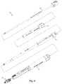
- FIG. 1is a perspective view of an example of a surgical biologics delivery system according to one embodiment of the disclosure
- FIG. 2is a plan view of the surgical biologics delivery system of FIG. 1 ;
- FIG. 3is another plan view of the surgical biologics delivery system of FIG. 1 , rotated 90° relative to the view of FIG. 2 ;
- FIG. 4is an exploded perspective view of the surgical biologics delivery system of FIG. 1 ;
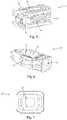
- FIG. 5is a perspective view of one example of a spinal implant suitable for use with the surgical biologics delivery system of FIG. 1 ;
- FIG. 6is a perspective view of a shim forming part of the spinal implant of FIG. 5 ;
- FIG. 7is a rear plan view of the shim of FIG. 6 ;
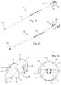
- FIG. 8is a perspective view of one example of an outer cannula forming part of the surgical biologics delivery system of FIG. 1 ;
- FIG. 9is another perspective view of the outer cannula of FIG. 8 ;
- FIG. 10is a plan view of one end of the outer cannula of FIG. 8 ;
- FIG. 11is a perspective view of an example of an inner cannula forming part of the surgical biologics delivery system of FIG. 1 ;
- FIG. 12is another perspective view of the inner cannula of FIG. 11 ;
- FIG. 13is a plan view of one end of the inner cannula of FIG. 11 ;
- FIG. 14is a perspective view of one end of the inner cannula of FIG. 11 ;
- FIG. 15is a perspective view of an example of a load cartridge and load cartridge tamp forming part of the surgical biologics delivery system of FIG. 1 ;
- FIG. 16is a perspective view of the load cartridge of FIG. 15 ;
- FIG. 17is another perspective view of the load cartridge of FIG. 15 ;
- FIG. 18is a perspective view of an example of a tamp forming part of the surgical biologics delivery system of FIG. 1 ;
- FIG. 19is another perspective view of the tamp of FIG. 18 ;
- FIG. 20is an enlarged perspective view of the proximal end of the tamp of FIG. 18 ;
- FIG. 21is an enlarged plan view of the proximal end of the tamp of FIG. 18 ;
- FIG. 22is an enlarged view of the proximal end engagement between the tamp of FIG. 18 and load cartridge of FIG. 15 according to one embodiment of the disclosure;
- FIG. 23is an enlarged view of the proximal end engagement between the tamp of FIG. 18 and load cartridge of FIG. 15 , with the end cap of the tamp removed;
- FIG. 24is an enlarged perspective view of the proximal end engagement between the tamp of FIG. 18 , load cartridge of FIG. 15 , and inner cannula of FIG. 11 according to one embodiment of the disclosure;
- FIG. 25is an enlarged plan view of the proximal end engagement between the tamp of FIG. 18 , load cartridge of FIG. 15 , and inner cannula of FIG. 11 ;
- FIG. 26is another enlarged plan view of the proximal end engagement between the tamp of FIG. 18 , load cartridge of FIG. 15 , and inner cannula of FIG. 11 , rotated 90° relative to the view of FIG. 25 ;
- FIG. 27is a perspective view of one step of an example method of using the surgical biologics delivery system of FIG. 1 according to one embodiment of the disclosure, comprising a step of introducing a spinal implant of FIG. 5 into a target disc space by way of the outer cannula of FIG. 8 ;
- FIG. 28is a perspective view of another step of an example method of using the surgical biologics delivery system of FIG. 1 according to one embodiment of the disclosure, comprising a step of inserting the inner cannula of FIG. 11 into the outer cannula of FIG. 8 ;
- FIG. 29is a perspective view of another step of an example method of using the surgical biologics delivery system of FIG. 1 according to one embodiment of the disclosure, comprising a step of inserting a load cartridge of FIG. 15 into the inner cannula of FIG. 11 ;
- FIG. 30is a perspective view of another step of an example method of using the surgical biologics delivery system of FIG. 1 according to one embodiment of the disclosure, comprising a step of advancing a tamp of FIG. 18 into the load cartridge of FIG. 15 ;
- FIG. 31is a perspective view of the proximal and distal engagements between the tamp of FIG. 18 , load cartridge of FIG. 15 , and inner cannula of FIG. 11 , with the tamp partially inserted;
- FIG. 32is a perspective view of the proximal and distal engagements between the tamp of FIG. 18 , load cartridge of FIG. 15 , and inner cannula of FIG. 11 , with the tamp fully inserted.
- the teachingsare directed to a biologics delivery system, comprising a cannula adapted for receiving a preloaded load cartridge and a cartridge tamp.
- the teachingsare directed to a system for receiving, removing, and replacing of preloaded load cartridges in a rapid and repeating manner. This is further facilitated by a system that can also rapidly deliver the biologics from a single load cartridge.
- the load cartridge and cartridge tampcan be adapted so that the cartridge tamp can capture and remove the load cartridge after delivery of fusion promoting material in the load cartridge.
- the biologics delivery systemcomprises a cannula having a proximal portion, a proximal end, a distal portion, a distal end, and an engagement feature to engage a spinal implant; the proximal portion having a proximal lumen with a first inner diameter, and the distal portion having a distal lumen with a second inner diameter; wherein, the cannula is adapted for receiving a load cartridge in the proximal lumen of the cannula, the load cartridge having a proximal portion, a first removal component, an elongated shaft, and a lumen. In some embodiments, there is no first removal component.
- the cartridge tampcan have an elongated shaft and a second removal component.
- the proximal lumen of the cannulacan be configured to open into the distal lumen of the cannula
- the lumen of the load cartridgecan be configured to open into the distal lumen of the cannula.
- the proximal lumen of the cannulacan be adapted to receive the elongated shaft of the load cartridge, and the distal lumen of the cannula can be adapted to receive the elongated shaft of the load cartridge.
- the proximal portion of the load cartridgecan be adapted to receive the elongated shaft of the cartridge tamp; and, the second removal component of the cartridge tamp can be adapted to (i) releasably connect with the first removal component and (ii) capture the load cartridge from the cannula when removing the cartridge tamp from the system.
- the biologics systemcan further comprise the load cartridge. In some embodiments, there is no first removal component or second removal component.
- the first removal componentcan be adapted to releasably engage with the second removal component using a friction fit connection between the first removal component and the second removal component.
- the first removal componentcan be adapted to releasably engage with the second removal component using a snap fit connection between the first removal component and the second removal component.
- the first removal componentis adapted to releasably engage with the second removal component using a thread fit connection between the first removal component and the second removal component.
- the first removal componentcan be adapted to releasably engage with the second removal component using a key and slot coupling connection between the first removal component and the second removal component.
- any connection known to one of skill in the artcan be used to connect the first and second components.
- the first removal component and second removal componentconnect using a magnetic connection.
- the connection between the first and second componentprovides a safe and efficient way for the surgeon to “capture” a spent load cartridge and replace it with an additional load cartridge, quickly, to deliver a desired amount of fusion promoting material in vivo.
- the proximal end of the cannulacan be further adapted to include a first indicator; and, likewise, the proximal portion of the load cartridge can be further adapted to include a second indicator complementary to the first indicator.
- an assembly of the cannula and load cartridgecan releasably fix the rotational position of the first removal component relative to the rotational position of the cannula to stop undesirable rotation between the cannula and load cartridge while holding the cannula in vivo to make the releasable connection between the first removal component and second removal component.
- the proximal end of the cartridge tampcan be further adapted to include a third indicator that is complementary to the assembly of the first and second indicators, such that the third indicator guides the cartridge tamp into the releasably-fixed assembly of the cannula and the load cartridge while making the releasable connection in vivo between the first removal component and second removal component.
- the first indicatorcan be configured to include a first prong extending proximally from the proximal end of the cannula and having a flat interior surface; the second indicator, likewise, can be configured with a outer-facing flat surface on the proximal portion of the load cartridge that is at least substantially complementary with the flat interior surface of the first prong; and, the cartridge tamp can further include a proximal cap having a recess as the third indicator, the recess being at least substantially complementary to the first prong.
- the alignment between the first and second indicators, and first, second, and third indicatorsprovides a safe and efficient way for the surgeon to align the system components to quickly capture a spent load cartridge and replace it with an additional load cartridge, quickly, to deliver a desired amount of fusion promoting material in vivo.
- the preloaded cartridgescan be designed to have any bore size, but they are particularly valuable in that they include a large bore size, never before available, to enable one of skill to deliver the biologics into the disc space safely, and faster, than current state-of-the-art systems.
- the load cartridgesare designed as “repeater cartridges”, with a configuration that delivers the fusion promoting material surprisingly quickly, and this is even further enhanced through additional quick-change features.
- the teachingsare also directed to a method of delivering biologics into an intervertebral disc space of a subject.
- the methodscan include placing a cannula into the intervertebral disc space, the cannula adapted for receiving a preloaded load cartridge, preloaded with fusion promoting material; and, delivering the fusion promoting material by pushing a cartridge tamp into the preloaded cartridge to apply pressure that forces the fusion promoting material into the intervertebral disc space.
- the methodscan include placing the cannula into the intervertebral disc space; inserting the load cartridge into the cannula, the load cartridge preloaded with fusion promoting material; and, delivering the fusion promoting material into the intervertebral disc space.
- the deliveringcan include inserting the cartridge tamp into the load cartridge and pushing the fusion promoting material into the intervertebral disc space with the cartridge tamp to create a first empty load cartridge; removing the first empty load cartridge; inserting an additional load cartridge into the cannula, the additional load cartridge preloaded with additional fusion promoting material; pushing the additional fusion promoting material into the intervertebral disc space with the cartridge tamp to create an additional empty load cartridge; removing the additional empty load cartridge; and, repeating the inserting of the additional load cartridge, the pushing of the additional load cartridge, and removing of the additional load cartridge until a desired amount of fusion promoting material has been delivered to the intervertebral space.
- the load cartridgesare administered in series, where the first cartridge is “load cartridge 1”, and each additional load cartridges, n, is an “n+1” th load cartridge, for example, where n can range from, perhaps, from 1 to 10.
- the methodscan further comprise inserting a spinal implant into the intervertebral disc space. And, in some embodiments, the methods can further comprise docking the distal end of the cannula to the spinal implant.
- the removing of the first load cartridge and the additional load cartridgecan include releasably engaging the first removal component with the second removal component using a friction fit connection between the first removal component and the second removal component.
- the removing of the first load cartridge and the additional load cartridgecan include releasably engaging the first removal component with the second removal component using a snap fit connection between the first removal component and the second removal component.
- the removing of the first load cartridge and the additional load cartridgecan include releasably engaging the first removal component with the second removal component using a thread fit connection between the first removal component and the second removal component.
- the removing of the first load cartridge and the additional load cartridgecan include releasably engaging the first removal component with the second removal component using a key and slot coupling connection between the first removal component and the second removal component.
- the methodsfurther include inserting an expandable shell into the intervertebral disc space. In some embodiments, the methods further include inserting a shim into the intervertebral disc space. In some embodiments, the methods further include inserting an expandable shell into the intervertebral disc space and inserting a shim into the expandable shell. And, in some embodiments, the methods further include expanding the expandable shell laterovertically.
- the keycan be a pin, a bead, or any protuberance known to one of skill in the art, for example; and, the slot can be any configuration that facilitates a rapid and releasable capture with the key, including an open slot, a closed slot, an open dimple, a closed dimple, and the like.
- a slotmay be continuous in dimension or tapered for a friction fit, stepped to narrow for a tightening friction fit, stepped to narrow and then wide for a snap fit, and the like or any combination thereof.
- a thread connectioncan be any threaded connection and can include a friction fit, for example.
- the biologics delivery systemcan comprise a cannula adapted for receiving a preloaded load cartridge and a cartridge tamp.
- the load cartridge and cartridge tampcan be adapted so that the cartridge tamp can capture and remove the load cartridge after delivery of fusion promoting material in the load cartridge.
- the systemsare designed for receiving, removing, and replacing of preloaded load cartridges in a rapid and repeating manner. This is further facilitated by systems that can also rapidly deliver the biologics from a single load cartridge.
- the load cartridge and cartridge tampcan be adapted so that the cartridge tamp can capture and remove the load cartridge after delivery of fusion promoting material in the load cartridge.
- biologicalsbone graft
- graftgraft material
- fusion promoting materialcan be used interchangeably, in some embodiments.
- Materials which may be placed or injected into the intevertebral spaceinclude solid or semi-solid grafting materials, bone from removed from patient's facet, an iliac crest harvest from the patient, and bone graft extenders such as hydroxyapatite, demineralized bone matrix, and bone morphogenic protein.
- solid or semi-solid grafting material componentsinclude solid fibrous collagen or other suitable hard hydrophilic biocompatible material. Some materials may also include swelling for further vertical expansion of the intervertebral disc space.
- the preloaded cartridgescan be designed to have any bore size, but they are particularly valuable in that they include a large bore size, never before available, to enable one of skill to deliver the biologics into the disc space safely, and faster, than current state-of-the-art systems.
- the load cartridgesare designed as “repeater cartridges”, with a configuration that delivers the fusion promoting material surprisingly quickly.
- the bore sizecan range from about 1.0 mm to about 10.0 mm in diameter, for example, the bore is no less than 5.0 mm in diameter in some embodiments, and any range therein in increments of 1.0 mm. In some embodiments, however, the bore size can range from about 5.0 mm to about 10.0 mm in diameter, or from about 5.0 mm to about 6.0 mm in diameter, and any range therein in increments of 1.0 mm. In some embodiments, the bore size can be no less in diameter than about 5.0 mm, about 6.0 mm, about 7.0 mm, about 8.0 mm, about 9.0 mm, about 10.0 mm, and any amount therein in increments of 1.0 mm.
- the bore sizecan be asymmetrical in dimensions, such that the height of the bore may not be equal to the width of the bore.
- the bore sizeranges from 5.0 mm to 6.00 mm in height, and from 9.0 mm to 16.00 mm in width.
- the bore sizeranges from 5.0 mm to 15.00 mm in height, and from about 9.0-15.0 mm in width.
- “height”can refer to the craniocaudal direction of the bore, and “width” is the transverse direction with respect to the anatomical position.
- the outer diameter of the elongated shaft of the cartridge tampis complementary to these dimensions for delivery of the fusion promoting material.
- the combination of the load cartridge and cartridge tampprovide a “capture” mechanism, as set-forth herein, in some embodiments.
- fusion-promoting materialmay include biologic bone, artificial bone matrix, collagen, protein, and the like, and these materials can be referred to as an allograft, autograft, xenograft, or synthetic bone graft material, for example.
- the premixing of graft materialcan include use of a plasma concentrate, blood, bone marrow, platelet rich plasma, intravenous fluids, and can add significantly to procedural time, as it is done repeatedly during current procedures.
- the particlescan range in size from about 0.5 mm to about 5.0 mm in maximum dimension, about 0.5 mm to 5.0 mm in mean particle dimension, or about 0.5 mm to 5.0 mm in average particle dimension, across the particular population in the load cartridge. In some embodiments, the particles can range in size from about 1.0 mm to about 3.0 mm in maximum dimension, about 1.0 mm to about 3.0 mm in mean particle dimension, or about 1.0 mm to about 3.0 mm in average particle dimension, across the particular population in the load cartridge, and these dimensions can vary in increments of 0.1 mm across the range, in some embodiments.
- the load cartridgescan have a variety of volumes.
- the load cartridgehas a volume capacity for bone graft material in a range from about 0.5 ml to about 20 ml.
- the load cartridgehas a volume capacity for bone graft material in a range from about 0.75 ml to about 15 ml.
- the load cartridgehas a volume capacity for bone graft material in a range from about 1.0 ml to about 10 ml.
- the load cartridgehas a volume capacity for bone graft material in a range from about 1.5 ml to about 5.0 ml.
- the load cartridgehas a volume capacity for bone graft material of about 0.5 ml, about 1.0 ml, about 1.5 ml, about 2.5 ml, about 3.0 ml, about 3.5 ml, about 4.0 ml, about 4.5 ml, about 5.0 ml, about 5.5 ml, about 6.0 ml, about 6.5 ml, about 7.0 ml, about 7.5 ml, about 8.0 ml, about 8.5 ml, about 9.0 ml, about 9.5 ml, about 10.0 ml, about 11.0 ml, about 12.0 ml, about 13.0 ml, about 14.0 ml, about 15.0 ml, or about 20 ml, and amounts or ranges therein in increments of 0.1 ml.
- kitscan also be used interchangeably, in some embodiments.
- a kitcan include one or more repeater cartridges and a cartridge tamp.
- a kitcan include one or more repeater cartridges, a cartridge tamp, and a cannula for delivering biologics.
- a kitcan include one or more repeater cartridges, a cartridge tamp, a cannula for delivering biologics, and an outer cannula for receiving the cannula for delivering biologics.
- a kitcan include one or more repeater cartridges, a cartridge tamp, a cannula for delivering biologics, and an outer cannula for delivering a spinal implant and receiving the cannula for delivering biologics.
- a kitcan include one or more repeater cartridges, a cartridge tamp, a cannula for delivering biologics, an outer cannula for delivering a spinal implant and receiving the cannula for delivering biologics, and a spinal implant.
- a kitwill include a laterovertically expanding spinal implant and shim as described herein by reference in at least PCT Application No. PCT/US18/43517, filed Jul. 24, 2018, which is hereby incorporated by reference herein in its entirety. Instructions for using each kit can be included.
- FIGS. 1-4illustrate an example of a surgical biologics delivery system 10 according to some embodiments.
- the surgical biologics delivery systemmay be used in a variety of orthopedic applications.
- the surgical biologics delivery system 10is described herein by example as being configured for use with a spinal implant 12 during a spinal fusion surgery.
- the example surgical biologics delivery system 10 described hereinincludes an outer cannula 14 , an inner cannula 16 , a load cartridge 18 , and a tamp 20 .
- the outer cannula 14defines the surgical access corridor from the sterile operative field to the surgical target site within the patient, in this case (by way of example) an intervertebral disc space.
- the outer cannula 14is sized and configured to allow passage of a variety of surgical instruments to access and prepare the target disc space as well as facilitate insertion of the spinal implant 12 and further receive the inner cannula 16 therein.
- the inner cannula 16is sized and configured to extend through the outer cannula 14 to facilitate introduction of biologics into the spinal implant 12 .
- the inner cannula 16is also configured to receive the load cartridge 18 , which is loaded with the biologics to be inserted into the disc space.
- the tamp 20is sized and configured to extend through the load cartridge 18 and inner cannula 16 to forcibly move the biologics from the load cartridge 18 through the inner cannula 16 and into the spinal implant 12 .
- the total length of the systemis designed to facilitate delivery of the biologics in a surgical setting.
- the total length of the systemcan range from about 70.0 mm to about 350.0 mm, from about 80.0 mm to about 300.0 mm, from about 90.0 mm to about 250.0 mm, from about 100.0 mm to about 200.0 mm, or any range or amount therein in increments of 1.0 mm.
- FIGS. 5-7depict one example of a spinal implant 12 suitable for use with the surgical biologics delivery system 10 described herein, according to some embodiments.
- the spinal implant 12may be one of the implants shown and described in commonly owned and PCT Application No. PCT/US18/43517, filed Jul. 24, 2018, the complete disclosure of which is incorporated by reference into this disclosure as if set-forth fully herein.
- the spinal implant 12 of the present exampleincludes an expandable shell 22 , shim 24 , and guide element 26 .
- the shell 22is sized and configured for insertion into the target disc space through the outer cannula 14 in a collapsed state and thereafter expanded within the disc space by insertion of the shim 24 into the shell 22 .
- the shim 24is also sized and configured for insertion through the outer cannula 14 .
- the collapsed shell 22has a generally rectangular shape, including a generally rectangular lateral cross-sectional shape, which as will be explained below allows for efficient passage through the outer cannula 14 .
- the shell 22further includes a plurality of graft windows 28 positioned on each face of the generally rectangular shell 22 to allow for seepage of biologics to facilitate osteogenesis through the implant 12 .
- the shim 24includes a distal aperture 30 and a plurality of graft windows 32 positioned on each face of the generally rectangular shim 24 .
- the distal aperture 30is sized and configured to receive the distal end of the inner cannula therein to enable application of the biologics to the implant.
- the distal aperture 30has a generally rectangular perimeter having a width dimension (e.g. the long edge of the rectangle) and height dimension (e.g. the short edge of the rectangle), however other shapes are possible.
- the graft windows 32 of the shimallow for seepage of biologics to facilitate osteogenesis through the implant 12 .
- the surgical implantcan include, for example, a laterovertically-expanding shell configured to create an intervertebral scaffolding system in vivo, the shell having a first body portion configured to engage a first vertebral endplate and a second body portion configured to engage a second vertebral endplate, the shell further including a collapsed state and an expanded state; a guide element that slideably engages with the distal region of the shell, and is configured for retaining the shell from lateral movement that exceeds the expanded state; and, a shim configured for in vivo introduction into the shell when the shell is in a collapsed state and thereafter causing expansion of the shell to an expanded state, the expansion occurring in a lateral direction and a vertical direction.
- the shellis configured to extend asymmetrically in the lateral direction.
- lateralcan be used as terms of relative orientation, meaning that the surgical implant can expand in at two directions that are normal to each other.
- the term “vertical”can be used herein synonymously with “cephalocaudal”, “craniocaudal”, and the like, meaning that the implant expands at least substantially in the vertical direction of the spine, at least substantially in the directions of the coronal and sagittal planes of the subject, expanding the intervertebral space by applying a force to the two vertebral endplates that define the upper and lower borders of the intervertebral space.
- the term “lateral”can be used herein synonymously with the term “transverse”, which encompasses the terms “mediolateral”, “anteromedial”, posteromedial”, and the like, meaning that the implant expands in any direction that is at least substantially in the direction of a transverse plane of the subject. This can include, for example, expanding the implant toward the annular walls of the disc space, in some embodiments, and away from the annular walls in some embodiments.
- the term “laterovertical”can be used, for example, to refer to an expansion that is at least substantially in the “cephalocaudal” or “craniocaudal” direction combined with an expansion that is at least substantially in the direction of a transverse plane, noting that the transverse plane can be used relative to the subject as a whole, or relative to an anatomical position within the subject, which transverse plane relative to the anatomical position can vary a bit in direction due to normal anatomical variation, or perhaps a disease or disorder.
- subject and patientcan be used interchangeably in some embodiments and refer to an animal such as a mammal including, but not limited to, non-primates such as, for example, a cow, pig, horse, cat, dog; and primates such as, for example, a monkey or a human.
- non-primatessuch as, for example, a cow, pig, horse, cat, dog
- primatessuch as, for example, a monkey or a human.
- non-primatessuch as, for example, a cow, pig, horse, cat, dog
- primatessuch as, for example, a monkey or a human.
- the terms “subject” and “patient”can also be applied to non-human biologic applications including, but not limited to, veterinary, companion animals, commercial livestock, and the like.
- an orientationis at least substantially on a plane or a direction when it's orientation deviates from the plane or direction by no more than 40%, no more than 30%, no more than 20%, no more than 10%, no more than 5%, no more than 1%, or no more than any amount or range therein in increments of 0.1%.
- the vertical expansion of the vertebral implant in an intervertebral spacecan occur, for example, in a direction that is still “craniocaudal” and is understood to be at least substantially parallel to the vertical axis of the intervertebral disc space, for example, such that the vertical axis of the intervertebral disc space is defined by a line connecting the center of the top vertebral endplate and the center of the bottom vertebral endplate defining that intervertebral space when combined with the annulus surrounding the space.
- the lateral expansion of the vertebral implant in an intervertebral spacecan occur, for example, in a direction that is at least substantially parallel to any direction of a transverse plane through the intervertebral disc space.
- the transverse plane of the intervertebral disc spacecan be defined by a transverse section of the annulus of the disc rather than a transverse section of the subject, the transverse plane being placed equidistant between the top vertebral endplate and the bottom vertebral endplate, the transverse section of the disc space varying from a transverse section of the subject as a whole, as it is tilted to account for any lordosis, kyphosis, scoliosis, or bone degeneration or disease which can alter the relative position of the intervertebral space within the subject from an otherwise pure interpretation of the orientation intended.
- the biologics delivery systemcomprises a cannula having a proximal portion, a proximal end, a distal portion, a distal end, and an engagement feature to engage a spinal implant; the proximal portion having a proximal lumen with a first inner diameter, and the distal portion having a distal lumen with a second inner diameter; wherein, the cannula is adapted for receiving a load cartridge in the proximal lumen of the cannula, the load cartridge having a proximal portion, a first removal component, an elongated shaft, and a lumen.
- the cartridge tampcan have an elongated shaft and a second removal component.
- the proximal lumen of the cannulacan be configured to open into the distal lumen of the cannula
- the lumen of the load cartridgecan be configured to open into the distal lumen of the cannula.
- the proximal lumen of the cannulacan be adapted to receive the elongated shaft of the load cartridge, and the distal lumen of the cannula can be adapted to receive the elongated shaft of the load cartridge.
- the proximal portion of the load cartridgecan be adapted to receive the elongated shaft of the cartridge tamp; and, the second removal component of the cartridge tamp can be adapted to (i) releasably connect with the first removal component and (ii) capture the load cartridge from the cannula when removing the cartridge tamp from the system.
- the biologics systemcan further comprise the load cartridge.
- FIGS. 8-10illustrate an example of an outer cannula 14 forming part of the surgical biologics delivery system 10 , according to some embodiments.
- the outer cannula 14comprises an elongated shaft having an interior lumen 34 extending longitudinally therethrough.
- the elongated shaftfurther includes a distal portion 36 having a distal end 38 and a proximal portion 40 having a proximal end 42 .
- the interior lumen 34has a generally rectangular cross-sectional shape, as best shown in FIG. 10 .
- the rectangular shapeallows for efficient passage of a collapsed spinal implant 12 as well as a shim 24 therethrough.
- the distal portion 36is configured to extend into a patient's body to the surgical target site, and has a generally rectangular outer peripheral cross-sectional shape to complement the peripheral shape of the interior lumen 34 so as to reduce the profile of the instrument and therefore minimize the impact on nearby body tissue.
- a distal aperture 44 formed in the distal end 38provides access to the interior lumen 34 .
- the proximal portion 40extends away from the patient's body and is generally cylindrical in shape.
- the proximal end 42includes an engagement recess 46 extending around the periphery of the proximal end 42 configured to facilitate attachment of additional instrumentation and/or accessories.
- the proximal end 42further includes a proximal recess 48 formed longitudinally within the proximal end 42 includes a generally planar bottom surface 50 and a cylindrical sidewall 52 extending proximally away from the bottom surface 50 .
- the bottom surface 50further includes a proximal aperture 54 formed therethrough to provide access to the interior lumen 34 .
- the proximal recess 48is sized and configured to receive at least a portion of the proximal portion 62 of the inner cannula 16 .
- the bottom surface 50provides a physical barrier to limit the advancement of the inner cannula 16 within the outer cannula 14 to prevent over-insertion.
- the sidewall 52engages the inner cannula 16 to prevent unwanted lateral movement of the inner cannula 16 while allowing for rotational movement of the inner cannula 16 within the outer cannula 14 to ensure proper engagement with the implanted spinal implant 12 before delivery of surgical biologics.
- the proximal end of the cannulafor example inner cannula 16
- the proximal portion of the load cartridgecan be further adapted to include a second indicator complementary to the first indicator.
- an assembly of the cannula and load cartridgecan releasably fix the rotational position of the first removal component relative to the rotational position of the cannula to stop undesirable rotation between the cannula and load cartridge while holding the cannula in vivo to make the releasable connection between the first removal component and second removal component.
- FIGS. 11-14illustrate an example of an inner cannula 16 forming part of the surgical biologics delivery system 10 according to some embodiments.
- the inner cannula 16comprises an elongated shaft including a distal portion 58 having a distal end 60 and a proximal portion 62 having a proximal end 64 .
- the distal portion 58is configured to extend through the outer cannula 14 to the surgical target site, and has a generally cylindrical interior lumen 56 extending therethrough.
- a distal aperture 66 formed in the distal end 60provides access to the interior lumen 56 .
- the distal end 60further includes an implant engagement feature 68 , shown by way of example as a pair of distally extending prongs.
- the implant engagement feature 68is configured to engage the implanted spinal implant 12 to dock the distal end 60 of the inner cannula 16 to the surgical implant 12 prior to delivery of surgical biologics.
- the implant engagement feature 68e.g. prongs
- the implant engagement feature 68has a width element (e.g. the distance between the outer edges of each of the prongs) that corresponds to the width dimension of the proximal aperture 30 and a height element (e.g. the height of each of the prongs) that corresponds to the height dimension of the proximal aperture 30 .
- the distal end 60is prevented from both lateral and rotational movement within the proximal aperture 30 , resulting in a stable docking interaction between the inner cannula 16 and the implant 12 .
- Any suitable means for dockingcan be used, such that the docking results in making a releasable contact with the implant in vivo.
- the docking meanscan have any shape, including round, square, rectangular, elliptical, sinusoidal, a combination thereof, and the like, and the docking of course, can include complementary shapes between the cannula and the implant.
- Such meanscan include a male/female type connection in some embodiments, for example, a straight tube type connector, a stepped tube type connector, a tapered tube type connector, a funnel type connector, a Luer-lock or Luer-slip type connector, a bayonet type connector, a compression type connector, or a slidably translational connection of any configuration, including prongs, tabs, pins, rods, tubes, etc, in some embodiments.
- connectioncan be a rotationally releasable tab and slot type connection, for example.
- a pinch-type or grab-type connectionmay be used, or perhaps a thread fit connection, or perhaps a clip-type connection, in some embodiments.
- the proximal portion 62includes (by way of example) a pair of opposing arcuate surfaces 70 and a pair of opposing planar surfaces 72 .
- the opposing arcuate surfaces 70are configured to engage the cylindrical sidewall 52 of the proximal recess 48 of the outer cannula 14 when the inner cannula 16 is inserted into the outer cannula 14 .
- the distance between the opposing arcuate surfacesis approximately equal to the diameter of the proximal recess 48 . This creates a flush engagement of the proximal portion 62 of the inner cannula 16 within the proximal recess 48 of the outer cannula 14 which allows for rotational movement (e.g.
- the proximal portion 62further includes a distal ledge 74 at the intersection of the distal portion 58 and proximal portion 62 , created due to the difference in size between the proximal and distal portions 62 , 58 , respectively (for example, the generally cylindrical distal portion 58 has a diameter that is smaller than the distance between both the opposing arcuate surfaces 70 and the opposing planar surfaces 72 .
- the distal ledge 74interacts with the bottom surface 50 of the proximal recess 48 to physically block further advancement of the inner cannula 16 within the outer cannula 14 .
- the proximal portion 62further includes a generally cylindrical interior lumen 76 sized and configured to receive the load cartridge 18 therein.
- the interior lumen 76is contiguous with the interior lumen 56 of the distal portion 58 and has a diameter that is greater than the diameter of the interior lumen 56 of the distal portion 58 .
- the proximal end 64includes a proximal recess 78 formed longitudinally within the proximal end 64 includes a generally planar bottom surface 80 and a cylindrical sidewall 82 extending proximally away from the bottom surface 80 .
- the bottom surface 80further includes a proximal aperture 84 formed therethrough to provide access to the interior lumen 76 .
- the proximal recess 78is sized and configured to receive at least a portion of the proximal portion 96 of the load cartridge 18 .
- the bottom surface 80provides a physical barrier to limit the advancement of the load cartridge 18 within the inner cannula 16 .
- the sidewall 82engages the load cartridge 18 to securely seat the load cartridge 18 within the proximal recess 78 .
- the proximal end 64further includes a pair of opposing proximal prongs 86 extending proximally away from the proximal end 64 .
- Each prong 86includes an outer-facing arcuate surface 88 and an inner-facing planar surface 90 .
- the inner-facing planar surfaces 90flushly engage the planar portions 118 of the upper outer-facing surface 116 of proximal portion 96 of the load cartridge 18 (described below) to ensure proper alignment and prevent rotation of the load cartridge 18 within the inner cannula 16 .
- FIGS. 15-17illustrate an example of a load cartridge 18 forming part of the surgical biologics delivery system 10 according to one embodiment of the disclosure.
- the load cartridge 18comprises a generally cylindrical elongated shaft 92 having a proximal portion 96 and a distal portion 94 .
- the elongated shaft 92is configured to mate with the proximal portion 62 of the inner cannula 16 , and has a generally cylindrical interior lumen 98 extending therethrough.
- a distal aperture 100 formed in the distal portion 94provides access to the interior lumen 98 .
- the proximal portion 96includes a generally cylindrical proximal recess 102 formed longitudinally within the proximal portion 96 includes a generally planar bottom surface 104 and a cylindrical sidewall 106 extending proximally away from the bottom surface 104 .
- the bottom surface 104further includes a proximal aperture 108 formed therethrough to provide access to the interior lumen 98 .
- the proximal recess 102is sized and configured to receive at least a portion of the handle portion 130 of the cartridge tamp 110 , which is described in further detail below.
- the sidewall 106includes an inner-facing surface 112 having a concave curvature to engage and seat the handle portion 130 of the cartridge tamp 110 , a lower outer-facing surface 114 having a convex curvature (e.g. as the outside of a cylinder), and an upper outer-facing surface 116 generally having a convex curvature but also including a pair of planar sections 118 on opposite sides of the sidewall 106 .
- the planar sections 118are sized and configured to flushly engage the inner-facing planar surfaces 90 of the prongs 86 of the inner cannula 16 when the load cartridge 18 is coupled with the inner cannula 16 .
- the lower cylindrical outer-facing surface 114has a smaller diameter than the upper outer-facing surface 116 such that, upon inserting the load cartridge 18 into the inner cannula 16 , the lower outer-facing surface 114 is seated within the proximal recess 78 while the upper outer-facing surface 116 remains outside the proximal recess 78 .
- the load cartridge removal featuresare optional, in some embodiments, as the systems and methods have other patentable features, but the load cartridge removal features significantly add to the ease of operation, safety, and reduction in procedural time.
- the first removal componentcan be adapted to releasably engage with the second removal component using a friction fit connection between the first removal component and the second removal component.
- the first removal componentcan be adapted to releasably engage with the second removal component using a snap fit connection between the first removal component and the second removal component.
- the first removal componentis adapted to releasably engage with the second removal component using a thread fit connection between the first removal component and the second removal component.
- the first removal componentcan be adapted to releasably engage with the second removal component using a key and slot coupling connection between the first removal component and the second removal component.
- the keycan be a pin, a bead, or any protuberance known to one of skill in the art, for example; and, the slot can be any configuration that facilitates a releasable capture with the key, including an open slot, a closed slot, an open dimple, a closed dimple, and the like.
- a slotmay be continuous in dimension or tapered for a friction fit, stepped to narrow for a tightening friction fit, stepped to narrow and then wide for a snap fit, and the like or any combination thereof.
- a thread connectioncan be any threaded connection and can include a friction fit, for example.
- the proximal portion 96further includes a pair of opposing slots 120 formed longitudinally into the upper outer-facing surface.
- the slots 120enable the load cartridge 18 to mate with tamp 20 to allow for easy removal of the load cartridge 18 from the inner cannula 16 after surgical biologics have been delivered to the target site.
- Each slot 120includes a pair of chamfers 122 at the intersection between the slot 120 and the proximal face 124 of the proximal portion 96 .
- the chamfers 122are angled such that they “lead into” the slot 120 .
- Each side of the slotincludes a recessed surface 126 positioned distal of the chamfer 122 and a ridge 128 between the chamfer 122 and the recess 126 .
- the space between the recessed surfaces 126is sized and configured to snugly receive at least a portion of the pin 142 of the tamp 20 (e.g. the distance between the recessed surfaces 126 is approximately equal to the diameter of the pin 142 ).
- the distance between the ridges 128is smaller than the diameter of the pin 142 , and therefore the ridges 128 must be laterally displaced to allow the pin 142 to pass by the ridges 128 and reach the recessed area of the slot 120 .
- the length of the slot 120enables the required lateral displacement.
- the ridges 128return to their original position, creating a barrier preventing egress of the pin 142 from the slot 120 and thereby creating a “snap fit” mating between the load cartridge 18 and the tamp 20 (See e.g. FIGS. 22-23 ).
- This matingis strong enough to enable simultaneous removal of the load cartridge 18 and tamp 20 from the inner cannula 16 (e.g. removal of the tamp 20 by the user removes the load cartridge 18 as well).
- the cartridge tamp 110includes a handle portion 130 and a pusher 132 .
- the handlemay be any structure that enables operability by a user.
- the pusher 132is shown by way of example as an elongated cylindrical shaft sized and configured to mate with the interior lumen 98 of the load cartridge 18 .
- the cartridge tamp 110is used to pack surgical biologic material into the interior lumen 98 of the load cartridge 18 prior to use of the load cartridge 18 in a surgical procedure.
- FIGS. 18-21illustrate an example of a tamp 20 forming part of the surgical biologics delivery system 10 , according to some embodiments.
- the tamp 20is used to physically relocate surgical biologic material from the load cartridge 18 to the implant 12 within the surgical target site by pushing the material through the inner cannula 16 .
- the tamp 20comprises a generally cylindrical elongated shaft 134 having a distal end 136 and a proximal end 138 .
- the elongated shaft 134is configured to mate with the interior lumen 56 of the inner cannula 16 and the interior lumen 98 of the load cartridge 18 .
- the distal end 136is shaped so that the distal end 136 may be at least partially received within the proximal aperture 30 of the implant 12 .
- the proximal end of the cartridge tampcan be further adapted to include a third indicator that is complementary to the assembly of the first and second indicators, such that the third indicator guides the cartridge tamp into the releasably-fixed assembly of the cannula and the load cartridge while making the releasable connection in vivo between the first removal component and second removal component.
- the first indicatorcan be configured to include a first prong extending proximally from the proximal end of the cannula and having a flat interior surface; the second indicator, likewise, can be configured with a outer-facing flat surface on the proximal portion of the load cartridge that is at least substantially complementary with the flat interior surface of the first prong; and, the cartridge tamp can further include a proximal cap having a recess as the third indicator, the recess being at least substantially complementary to the first prong.
- the proximal end 138includes an end cap 140 and a pin 142 .
- the end cap 138has a generally cylindrical outer surface 144 and a distal recess 146 formed longitudinally within the distal end of the end cap 140 .
- the distal recess 146includes a generally planar end surface 148 and a cylindrical sidewall 150 extending distally away from the end surface 148 .
- the elongated shaft 134extends distally from the center of the end surface 148
- the distal recess 146is sized and configured to receive at least a portion of the proximal portion 96 of the load cartridge 18 therein.
- the distal recess 146is configured to receive the upper outer-facing surface 116 portion of the proximal portion 96 therein.
- the sidewall 150includes a pair of opposing longitudinal recesses 152 sized and configured to receive the prongs 86 of the inner cannula 16 therein as the tamp 20 is nearing full insertion (See, e.g. FIGS. 24-26 ).
- the outer surface 144further includes a handle element 154 configured to enable efficient handling by a user.
- the handle element 154is shown as a friction element (e.g. surface roughening).
- the pin 142is generally cylindrical in shape and extends between opposite points on the cylindrical sidewall 150 and through the elongated shaft 134 at a point on the elongated shaft 134 that is vertically displaced from the end surface 148 .
- FIGS. 22-23illustrate by way of example the interaction between the tamp 20 and load cartridge 18 as described above, according to some embodiments.
- FIGS. 24-26illustrate by way of example the interaction between the tamp 20 and the inner cannula 16 as described above, according to some embodiments.
- Methods of delivering biologics into an intervertebral disc space of a subjectcan include a variety of steps.
- the methodscan include placing a cannula into the intervertebral disc space, the cannula adapted for receiving a preloaded load cartridge, preloaded with fusion promoting material; and, delivering the fusion promoting material by pushing a cartridge tamp into the preloaded cartridge to apply pressure that forces the fusion promoting material into the intervertebral disc space.
- the methodscan include placing the cannula into the intervertebral disc space; inserting the load cartridge into the cannula, the load cartridge preloaded with fusion promoting material; and, delivering the fusion promoting material into the intervertebral disc space.
- the deliveringcan include inserting the cartridge tamp into the load cartridge and pushing the fusion promoting material into the intervertebral disc space with the cartridge tamp to create a first empty load cartridge; removing the first empty load cartridge; inserting an additional load cartridge into the cannula, the additional load cartridge preloaded with additional fusion promoting material; pushing the additional fusion promoting material into the intervertebral disc space with the cartridge tamp to create an additional empty load cartridge; removing the additional empty load cartridge; and, repeating inserting the additional load cartridge, pushing the additional load cartridge, and removing the additional load cartridge until a desired amount of fusion promoting material has been delivered to the intervertebral space.
- the load cartridgesare administered in series, where the first cartridge is “load cartridge 1”, and each additional load cartridges, n, is an “n+1” th load cartridge, for example, where n can range from, perhaps, from 1 to 10.
- the methodscan further comprise inserting a spinal implant into the intervertebral disc space. And, in some embodiments, the methods can further comprise docking the distal end of the cannula to the spinal implant.
- the insertion of the spinal implantcan be done using a first cannula, which can be referred to as an outer cannula in some embodiments. This first cannula, however, can either be removed for a subsequent insertion of the cannulas taught herein for receiving the load cartridges, or it can remain in place during the biologics delivery procedure as the “outer cannula”, such that it is large enough to accept an insertion of the cannulas taught herein for receiving the load cartridges.
- the removing of the first load cartridge and the additional load cartridgecan include releasably engaging the first removal component with the second removal component using a friction fit connection between the first removal component and the second removal component.
- the removing of the first load cartridge and the additional load cartridgecan include releasably engaging the first removal component with the second removal component using a snap fit connection between the first removal component and the second removal component.
- the removing of the first load cartridge and the additional load cartridgecan include releasably engaging the first removal component with the second removal component using a thread fit connection between the first removal component and the second removal component.
- the removing of the first load cartridge and the additional load cartridgecan include releasably engaging the first removal component with the second removal component using a key and slot coupling connection between the first removal component and the second removal component.
- any releasably engaging means known to those of skillcan be used, such that the cartridge tamp can releasably capture and remove a spent load cartridge.
- such a means for releasably capturing a spent load cartridgemay include, for example, a connection of any configuration, including prongs, tabs, pins, rods, tubes, etc, in some embodiments, that can slidably or rotational capture and release a load cartridge from the cannula.
- connectioncan be a rotationally releasable tab and slot type connection, or perhaps a peg/pin and slot type connection, for example.
- a pinch-type or grab-type connectionmay be used, or perhaps a thread fit connection, or perhaps even a clip-type connection, in some embodiments, as a means for releasably capturing the spent load cartridge.
- the methodsfurther include inserting an expandable shell into the intervertebral disc space. In some embodiments, the methods further include inserting a shim into the intervertebral disc space. In some embodiments, the methods further include inserting an expandable shell into the intervertebral disc space and inserting a shim into the expandable shell. And, in some embodiments, the methods further include expanding the expandable shell laterovertically.
- FIGS. 27-32illustrate various steps in a example method of using the surgical biologics delivery system 10 of the present disclosure, according to some embodiments.
- FIG. 27illustrates a portion of a spinal column 2 , including a surgical target comprising an intervertebral disc space 4 located between adjacent vertebrae 6 , 8 .
- the disc space 4has already been prepared (e.g. damaged disc removed, endplates prepared for implant, etc.) and a spinal implant 12 has been inserted into the disc space 4 through the outer cannula 14 .
- the distal portion 36 of the outer cannula 14is sized to facilitate partial insertion into the disc space.
- the next stepis to insert the inner cannula 16 into the outer cannula 14 such that the distal end 60 of the inner cannula 16 engages with the proximal aperture 30 of the shim 24 of the spinal implant 12 , as shown by way of example in FIG. 28 .
- the next stepis to insert a load cartridge 18 into the proximal portion 62 of the inner cannula 16 .
- the load cartridge 18has been preloaded with surgical biologics material prior to insertion in to the inner cannula 16 , however the step of loading the load cartridge 18 with biologics may be performed after the load cartridge 18 has been inserted into the inner cannula 16 .
- biologics materialmay be inserted directly into the inner cannula 16 without the use of the load cartridge 18 , if desired.
- the next stepis to insert the elongated shaft 134 of the tamp into the load cartridge 18 and apply a distal force to physically move the surgical biologics material from the load cartridge 18 through the inner cannula 16 and into the spinal implant 12 and intervertebral disc space 4 , where it will interact with the vertebral endplates to generate new bone growth through the implant 12 and across the disc space 4 .
- the load cartridgescan be referred to as “repeater” cartridges, in some embodiments, as they are designed for rapid use and replacement during a surgical procedure, and provide surprising results in advancements of procedural speed, ease of operation, and safety.
- a replacement of the load cartridgeoccurs from the time the cartridge becomes empty and is replaced with a fresh cartridge.
- the replacement timecan range from 5 seconds to 60 seconds, from 10 seconds to 45 seconds, from 20 seconds to 30 seconds, or any range therein in increments of 1 second.
- the replacement time of a load cartridgecan be about 5 seconds, 10 seconds, 15 seconds, 20 seconds, 25 seconds, 30 seconds, 35 seconds, 40 seconds, 45 seconds, 50 seconds, 55 seconds, 60 seconds, or any amount therein in increments of 1 second.
- the “bore” or lumen of the cannula used to receive the load cartridge and deliver the fusion promoting materialis large to facilitate a fast delivery into the intervertebral space.
- the bore sizecan range from about 1.0 mm to about 10.0 mm in diameter, for example, the bore is no less than 5.0 mm in diameter in some embodiments, and any range therein in increments of 1.0 mm. In some embodiments, however, the bore size can range from about 5.0 mm to about 10.0 mm in diameter, or from about 5.0 mm to about 6.0 mm in diameter, and any range therein in increments of 1.0 mm.
- the bore sizecan be no less in diameter than about 5.0 mm, about 6.0 mm, about 7.0 mm, about 8.0 mm, about 9.0 mm, about 10.0 mm, and any amount therein in increments of 1.0 mm.
- the bore sizecan be asymmetrical in dimensions, such that the height of the bore may not be equal to the width of the bore.
- the bore sizeranges from 5.0 mm to 6.00 mm in height, and from 9.0 mm to 16.00 mm in width.
- the bore sizeranges from 5.0 mm to 15.00 mm in height, and from about 9.0-15.0 mm in width.
- “height”is a term that can refer to the craniocaudal direction of the bore
- widthis a term that can refer to the transverse direction with respect to the anatomical position of the subject.
- FIG. 31illustrates the relative positioning of the various components of the surgical biologics delivery system 10 just prior to final advancement of the tamp 20 into the load cartridge 18 and inner cannula 16 , according to some embodiments.
- the spinal implant 12is represented by the shim 24 (e.g. the expandable shell 22 has been omitted), which is shown in transparent form, and the outer cannula 14 is omitted.
- the inner cannula 16is docked to the shim 24 by virtue of the implant engagement feature 68 (e.g. distal prongs) being inserted into the proximal aperture 30 of the shim 24 .
- the implant engagement feature 68e.g. distal prongs
- the load cartridge 18is inserted into the inner cannula 16 and is in proper alignment due to the prongs 86 .
- the end cap 140 of the tamp 20is positioned such that the sidewall recesses 152 are aligned with the prongs 86 of the inner cannula 16 and the pin 142 is aligned with the slot 120 .
- FIG. 32illustrates the relative positioning of the various components of the surgical biologics delivery system 10 after final advancement of the tamp 20 into the load cartridge 18 and inner cannula 16 , according to some embodiments.
- the pin 142Upon final advancement of the tamp 20 , the pin 142 will advance into the slot 120 until it snaps into the recessed region 126 of the slot 120 .
- the prongs 86 of the inner cannula 16are fully inserted into the sidewall recesses 152 of the end cap 140 of the tamp 20 , ensuring proper alignment of the tamp 20 and also preventing further insertion of the tamp 20 in the event that a load cartridge 18 is not used.
- the distal end 136 of the elongated shaft 134is inserted into the implant 12 by way of aperture 30 .
- the biologics material 9has been fully deposited into the implant 12 and fills the disc space 4 by way of egress through graft windows 32 in the shim 24 and similar graft windows 28 in the expandable shell (not shown).
- the usermay remove the tamp 20 by gripping the handle element 154 and exerting a proximal force to pull the tamp 20 out of the inner cannula 16 .
- the load cartridge 18is removed from the inner cannula 16 with the tamp 20 .
- the inner cannula 16may then be removed from the target site by exerting a proximal force on the inner cannula 16 to disengage from the implant 12 and remove the inner cannula 16 from the outer cannula 14 .
- the outer cannula 12my then be removed in a similar fashion, and the surgical wound may then be closed.
Landscapes
- Health & Medical Sciences (AREA)
- Orthopedic Medicine & Surgery (AREA)
- Engineering & Computer Science (AREA)
- Biomedical Technology (AREA)
- Life Sciences & Earth Sciences (AREA)
- Transplantation (AREA)
- Neurology (AREA)
- Animal Behavior & Ethology (AREA)
- Veterinary Medicine (AREA)
- Public Health (AREA)
- General Health & Medical Sciences (AREA)
- Heart & Thoracic Surgery (AREA)
- Vascular Medicine (AREA)
- Oral & Maxillofacial Surgery (AREA)
- Cardiology (AREA)
- Surgery (AREA)
- Physical Education & Sports Medicine (AREA)
- Nuclear Medicine, Radiotherapy & Molecular Imaging (AREA)
- Medical Informatics (AREA)
- Molecular Biology (AREA)
- Prostheses (AREA)
- Surgical Instruments (AREA)
Abstract
Description
Claims (20)
Priority Applications (1)
| Application Number | Priority Date | Filing Date | Title |
|---|---|---|---|
| US16/113,040US10709578B2 (en) | 2017-08-25 | 2018-08-27 | Surgical biologics delivery system and related methods |
Applications Claiming Priority (2)
| Application Number | Priority Date | Filing Date | Title |
|---|---|---|---|
| US201762550557P | 2017-08-25 | 2017-08-25 | |
| US16/113,040US10709578B2 (en) | 2017-08-25 | 2018-08-27 | Surgical biologics delivery system and related methods |
Publications (2)
| Publication Number | Publication Date |
|---|---|
| US20190060085A1 US20190060085A1 (en) | 2019-02-28 |
| US10709578B2true US10709578B2 (en) | 2020-07-14 |
Family
ID=65434092
Family Applications (1)
| Application Number | Title | Priority Date | Filing Date |
|---|---|---|---|
| US16/113,040ActiveUS10709578B2 (en) | 2017-08-25 | 2018-08-27 | Surgical biologics delivery system and related methods |
Country Status (1)
| Country | Link |
|---|---|
| US (1) | US10709578B2 (en) |
Cited By (1)
| Publication number | Priority date | Publication date | Assignee | Title |
|---|---|---|---|---|
| US11224522B2 (en)* | 2017-07-24 | 2022-01-18 | Integrity Implants Inc. | Surgical implant and related methods |
Families Citing this family (10)
| Publication number | Priority date | Publication date | Assignee | Title |
|---|---|---|---|---|
| US8663332B1 (en) | 2012-12-13 | 2014-03-04 | Ouroboros Medical, Inc. | Bone graft distribution system |
| US9186259B2 (en) | 2013-09-09 | 2015-11-17 | Ouroboros Medical, Inc. | Expandable trials |
| US9060876B1 (en) | 2015-01-20 | 2015-06-23 | Ouroboros Medical, Inc. | Stabilized intervertebral scaffolding systems |
| US9883953B1 (en) | 2016-09-21 | 2018-02-06 | Integrity Implants Inc. | Stabilized laterovertically-expanding fusion cage systems with tensioner |
| JP7085554B2 (en) | 2017-01-10 | 2022-06-16 | インテグリティ インプランツ インコーポレイテッド | Deployable intervertebral fusion device |
| JP7572857B2 (en) | 2018-03-01 | 2024-10-24 | インテグリティ インプランツ インコーポレイテッド | Expandable Fusion Device with Independent Deployment System |
| US11273053B2 (en)* | 2018-12-20 | 2022-03-15 | Integrity Implants Inc. | Bone graft cartridge and bone graft delivery system |
| US11484416B2 (en) | 2019-06-04 | 2022-11-01 | DePuy Synthes Products, Inc. | Implant insertion tool for implanting an acetabular component and associated surgical method |
| EP4171448A4 (en) | 2020-07-20 | 2025-02-12 | Integrity Implants Inc. | EXPANDABLE FUSION DEVICE WITH INDEPENDENT EXPANSION SYSTEMS |
| US20240050237A1 (en)* | 2020-12-16 | 2024-02-15 | K2M, Inc. | Augmentable Expanding Implant |
Citations (211)
| Publication number | Priority date | Publication date | Assignee | Title |
|---|---|---|---|---|
| US4309777A (en) | 1980-11-13 | 1982-01-12 | Patil Arun A | Artificial intervertebral disc |
| US4733665A (en) | 1985-11-07 | 1988-03-29 | Expandable Grafts Partnership | Expandable intraluminal graft, and method and apparatus for implanting an expandable intraluminal graft |
| US4759766A (en) | 1984-09-04 | 1988-07-26 | Humboldt-Universitaet Zu Berlin | Intervertebral disc endoprosthesis |
| US4820305A (en) | 1986-11-03 | 1989-04-11 | Harms Juergen | Place holder, in particular for a vertebra body |
| US4997432A (en) | 1988-03-23 | 1991-03-05 | Waldemar Link Gmbh & Co. | Surgical instrument set |
| US5192327A (en) | 1991-03-22 | 1993-03-09 | Brantigan John W | Surgical prosthetic implant for vertebrae |
| US5221261A (en) | 1990-04-12 | 1993-06-22 | Schneider (Usa) Inc. | Radially expandable fixation member |
| WO1996040015A1 (en) | 1995-06-07 | 1996-12-19 | Michelson Gary K | Lordotic interbody spinal fusion implants |
| US5658336A (en) | 1994-03-18 | 1997-08-19 | Pisharodi; Madhavan | Rotating, locking, middle-expanded intervertebral disk stabilizer |
| US5976187A (en) | 1997-01-21 | 1999-11-02 | Spinal Innovations, L.L.C. | Fusion implant |
| US5980522A (en) | 1994-07-22 | 1999-11-09 | Koros; Tibor | Expandable spinal implants |
| US5980552A (en) | 1994-03-17 | 1999-11-09 | Medinol Ltd. | Articulated stent |
| US6039761A (en) | 1997-02-12 | 2000-03-21 | Li Medical Technologies, Inc. | Intervertebral spacer and tool and method for emplacement thereof |
| EP1011503A1 (en) | 1997-02-06 | 2000-06-28 | Surgical Dynamics, Inc. | Expandable non-threaded spinal fusion device |
| WO2000044319A1 (en) | 1999-01-27 | 2000-08-03 | Disc-O-Tech Medical Technologies, Ltd. | Expandable intervertebral spacer |
| US6102950A (en) | 1999-01-19 | 2000-08-15 | Vaccaro; Alex | Intervertebral body fusion device |
| US6176882B1 (en) | 1998-02-20 | 2001-01-23 | Biedermann Motech Gmbh | Intervertebral implant |
| US6193757B1 (en) | 1998-10-29 | 2001-02-27 | Sdgi Holdings, Inc. | Expandable intervertebral spacers |
| WO2001066047A1 (en) | 2000-03-08 | 2001-09-13 | Loubert Suddaby | Expandable intervertebral fusion implant having improved stability |
| US20020040243A1 (en) | 1996-09-13 | 2002-04-04 | David Attali | Method and apparatus for providing proper vertebral spacing |
| US6368351B1 (en) | 2001-03-27 | 2002-04-09 | Bradley J. Glenn | Intervertebral space implant for use in spinal fusion procedures |
| US6375682B1 (en) | 2001-08-06 | 2002-04-23 | Lewis W. Fleischmann | Collapsible, rotatable and expandable spinal hydraulic prosthetic device |
| US6409766B1 (en) | 1998-07-30 | 2002-06-25 | Expanding Concepts, Llc | Collapsible and expandable interbody fusion device |
| US6419705B1 (en) | 1999-06-23 | 2002-07-16 | Sulzer Spine-Tech Inc. | Expandable fusion device and method |
| US6432107B1 (en) | 2000-01-15 | 2002-08-13 | Bret A. Ferree | Enhanced surface area spinal fusion devices |
| US6436119B1 (en) | 1999-09-30 | 2002-08-20 | Raymedica, Inc. | Adjustable surgical dilator |
| EP1233732A1 (en) | 2000-02-04 | 2002-08-28 | MICHELSON, Gary Karlin | Expandable push-in interbody spinal fusion implant |
| US6443989B1 (en) | 2000-12-04 | 2002-09-03 | Roger P. Jackson | Posterior expandable fusion cage |
| US6482235B1 (en) | 1999-08-18 | 2002-11-19 | Intrinsic Orthopedics, Inc. | Devices and methods of vertebral disc augmentation |
| US6488710B2 (en) | 1999-07-02 | 2002-12-03 | Petrus Besselink | Reinforced expandable cage and method of deploying |
| US20030074075A1 (en) | 2001-08-27 | 2003-04-17 | Thomas James C. | Expandable implant for partial disc replacement and reinforcement of a disc partially removed in a discectomy and for reduction and maintenance of alignment of cancellous bone fractures and methods and apparatuses for same |
| US20030083746A1 (en) | 2001-10-31 | 2003-05-01 | Kuslich Stephen D. | Vertebral spacer for spinal stabilization |
| US6575899B1 (en) | 1999-10-20 | 2003-06-10 | Sdgi Holdings, Inc. | Methods and instruments for endoscopic interbody surgical techniques |
| US6582439B1 (en) | 2001-12-28 | 2003-06-24 | Yacmur Llc | Vertebroplasty system |
| US6582441B1 (en) | 2000-02-24 | 2003-06-24 | Advanced Bionics Corporation | Surgical insertion tool |
| US6582467B1 (en) | 2000-10-31 | 2003-06-24 | Vertelink Corporation | Expandable fusion cage |
| US6595998B2 (en) | 2001-03-08 | 2003-07-22 | Spinewave, Inc. | Tissue distraction device |
| US6620169B1 (en)* | 1999-08-26 | 2003-09-16 | Spineology Group, Llc. | Tools and method for processing and injecting bone graft |
| US6666891B2 (en) | 2000-11-13 | 2003-12-23 | Frank H. Boehm, Jr. | Device and method for lumbar interbody fusion |
| US20040010315A1 (en) | 2002-03-29 | 2004-01-15 | Song John K. | Self-expanding intervertebral device |
| US20040024463A1 (en) | 2001-08-27 | 2004-02-05 | Thomas James C. | Expandable implant for partial disc replacement and reinforcement of a disc partially removed in a discectomy and for reduction and maintenance of alignment of cancellous bone fractures and methods and apparatuses for same |
| US6821298B1 (en) | 2000-04-18 | 2004-11-23 | Roger P. Jackson | Anterior expandable spinal fusion cage system |
| US6821276B2 (en) | 1999-08-18 | 2004-11-23 | Intrinsic Therapeutics, Inc. | Intervertebral diagnostic and manipulation device |
| US6893464B2 (en) | 2002-03-05 | 2005-05-17 | The Regents Of The University Of California | Method and apparatus for providing an expandable spinal fusion cage |
| EP1532949A1 (en) | 2003-11-20 | 2005-05-25 | Kyungwon Medical Co., Ltd. | Expandable intervertebral fusion cage |
| US20050256576A1 (en) | 2004-05-13 | 2005-11-17 | Moskowitz Nathan C | Artificial expansile total lumbar and thoracic discs for posterior placement without supplemental instrumentation and its adaptation for anterior placement of artificial cervical, thoracic and lumbar discs |
| US7018415B1 (en) | 2002-09-23 | 2006-03-28 | Sdgi Holdings, Inc. | Expandable spinal fusion device and methods of promoting spinal fusion |
| US20060100706A1 (en) | 2004-11-10 | 2006-05-11 | Shadduck John H | Stent systems and methods for spine treatment |
| US20060122701A1 (en) | 2004-11-23 | 2006-06-08 | Kiester P D | Posterior lumbar interbody fusion expandable cage with lordosis and method of deploying the same |
| US20060167547A1 (en) | 2005-01-21 | 2006-07-27 | Loubert Suddaby | Expandable intervertebral fusion implants having hinged sidewalls |
| US7087055B2 (en) | 2002-06-25 | 2006-08-08 | Sdgi Holdings, Inc. | Minimally invasive expanding spacer and method |
| US20060287729A1 (en) | 2005-06-15 | 2006-12-21 | Jerome Segal | Mechanical apparatus and method for artificial disc replacement |
| US7204853B2 (en) | 2003-08-05 | 2007-04-17 | Flexuspine, Inc. | Artificial functional spinal unit assemblies |
| US7214243B2 (en) | 2002-10-21 | 2007-05-08 | 3Hbfm, Llc | Intervertebral disk prosthesis |
| US7217293B2 (en) | 2003-11-21 | 2007-05-15 | Warsaw Orthopedic, Inc. | Expandable spinal implant |
| US20070118222A1 (en) | 2005-11-21 | 2007-05-24 | Vertegen, Inc. | Intervertebral devices and methods |
| WO2007076374A2 (en) | 2005-12-19 | 2007-07-05 | Stout Medical Group, L.P. | Expandable support device and method of using the same |
| US20070173939A1 (en) | 2005-12-23 | 2007-07-26 | The Board Of Trustees Of The Leland Stanford Junior University | Systems and methods for fixation of bone with an expandable device |
| US20070219634A1 (en) | 2004-09-21 | 2007-09-20 | Greenhalgh E S | Expandable support device and method of use |
| US20080009876A1 (en) | 2006-07-07 | 2008-01-10 | Meera Sankaran | Medical device with expansion mechanism |
| WO2008005627A2 (en) | 2006-07-06 | 2008-01-10 | Lanx, Llc | Expandable spinal fusion cage |
| US20080021556A1 (en) | 2006-07-21 | 2008-01-24 | Edie Jason A | Expandable vertebral implant and methods of use |
| WO2008033457A2 (en) | 2006-09-14 | 2008-03-20 | The University Of Toledo | Variable height vertebral body replacement implant |
| WO2008035849A1 (en) | 2006-09-23 | 2008-03-27 | Nam Soo Song | Expandable jacking curette for bone fusion surgery |
| US20080147193A1 (en) | 2006-11-23 | 2008-06-19 | Wilfried Matthis | Expandable intervertebral implant |
| WO2008089252A2 (en) | 2007-01-16 | 2008-07-24 | Mi4Spine, Llc | Minimally invasive interbody device assembly |
| US20080234687A1 (en) | 2005-08-16 | 2008-09-25 | Laurent Schaller | Devices for treating the spine |
| WO2008121162A1 (en) | 2006-11-29 | 2008-10-09 | Mi4Spine, Llc | Disc space preparation device for spinal surgery |
| US20080281424A1 (en) | 2006-11-29 | 2008-11-13 | John Parry | Orthopaedic Implants and Prostheses |
| US20080281346A1 (en) | 2005-12-19 | 2008-11-13 | Stout Medical Group, L.P. | Expandable support device |
| US20090018524A1 (en) | 2005-12-19 | 2009-01-15 | Stout Medical Group, L.P. | Expandable delivery device |
| JP2009505686A (en) | 2005-07-14 | 2009-02-12 | スタウト メディカル グループ, エル.ピー. | Expandable support device and method of use |
| US20090076607A1 (en) | 2007-09-19 | 2009-03-19 | Arthur Martinus Aalsma | Collapsible and Expandable Device and Methods of Using Same |
| US7544208B1 (en) | 2004-05-03 | 2009-06-09 | Theken Spine, Llc | Adjustable corpectomy apparatus |
| US20090222043A1 (en) | 2004-10-20 | 2009-09-03 | Moti Altarac | Interspinous process spacer instrument system with deployment indicator |
| US20090234389A1 (en) | 2008-03-11 | 2009-09-17 | Fong-Ying Chuang | Interspinous spinal fixation apparatus |
| US20090281551A1 (en) | 2008-05-07 | 2009-11-12 | George Frey | Methods and apparatus for insertion of intervertebral implants and devices therefor |
| US7621950B1 (en) | 1999-01-27 | 2009-11-24 | Kyphon Sarl | Expandable intervertebral spacer |
| US7643884B2 (en) | 2005-01-31 | 2010-01-05 | Warsaw Orthopedic, Inc. | Electrically insulated surgical needle assembly |
| US20100010542A1 (en) | 2006-01-09 | 2010-01-14 | Jackson Roger P | Flexible spinal stbilization assembly with spacer having off-axis core member |
| US20100010633A1 (en) | 2008-07-10 | 2010-01-14 | Kyphon Sarl | Deployable Arc Fusion Cage and Methods Associated Therewith |
| US7655046B2 (en) | 2005-01-20 | 2010-02-02 | Warsaw Orthopedic, Inc. | Expandable spinal fusion cage and associated instrumentation |
| US20100042218A1 (en) | 2008-08-13 | 2010-02-18 | Nebosky Paul S | Orthopaedic implant with porous structural member |
| US7678148B2 (en) | 2004-07-23 | 2010-03-16 | Warsaw Orthopedic, Inc. | Expandable spinal implant having interlocking geometry for structural support |
| US7731751B2 (en) | 2005-03-31 | 2010-06-08 | Life Spine, Inc. | Expandable spinal devices and method of insertion |
| WO2010077359A1 (en) | 2008-12-30 | 2010-07-08 | Mitchell Hardenbrook | Expandable interbody implant and method |
| US20100198352A1 (en) | 2006-07-21 | 2010-08-05 | Warsaw Orthopedic, Inc. | Implant with Nested Members and Methods of Use |
| US7771473B2 (en) | 2006-07-06 | 2010-08-10 | Lanx, Inc. | Expandable spinal fusion cage |
| US20100217325A1 (en) | 2008-11-03 | 2010-08-26 | Hochschuler Stephen H | Expandable spinal support device with attachable members and methods of use |
| US20100222884A1 (en) | 2008-11-12 | 2010-09-02 | Stout Medical Group, L.P. | Fixation device and method |
| US20100234956A1 (en) | 2007-03-28 | 2010-09-16 | David Attia | Expanding cage for vertebral surgery |
| EP2237748A1 (en) | 2008-01-17 | 2010-10-13 | Synthes GmbH | An expandable intervertebral implant and associated method of manufacturing the same |
| US7819921B2 (en) | 2005-08-12 | 2010-10-26 | Coalign Innovations, Inc. | Linearly expanding spine cage for enhanced spinal fusion |
| US7828845B2 (en) | 2000-10-25 | 2010-11-09 | Warsaw Orthopedic, Inc. | Laterally expanding intervertebral fusion device |
| US7828849B2 (en) | 2003-02-03 | 2010-11-09 | Warsaw Orthopedic, Inc. | Expanding interbody implant and articulating inserter and method |
| US20100292796A1 (en) | 2009-05-14 | 2010-11-18 | Stout Medical Group, L.P. | Expandable support device and method of use |
| US7846206B2 (en) | 2004-06-09 | 2010-12-07 | Vexim Sas | Methods and apparatuses for bone restoration |
| US7850733B2 (en) | 2004-02-10 | 2010-12-14 | Atlas Spine, Inc. | PLIF opposing wedge ramp |
| US7862618B2 (en) | 2006-07-19 | 2011-01-04 | Warsaw Orthopedic, Inc. | Expandable vertebral body implants and methods of use |
| US20110022090A1 (en) | 2009-06-23 | 2011-01-27 | Osteomed, L.P. | Spinous process fusion implants |
| US7879098B1 (en) | 2005-10-19 | 2011-02-01 | Simmons Jr James W | Expandable lordosis stabilizing cage |
| US20110029082A1 (en) | 2008-03-14 | 2011-02-03 | Synthes Usa, Llc | Nested expandable sleeve implant |
| US20110046748A1 (en) | 2006-09-12 | 2011-02-24 | Orthocare Innovations, Llc | Pump system for prosthesis |
| US7909872B2 (en) | 2005-06-03 | 2011-03-22 | Zipnick Richard I | Minimally invasive apparatus to manipulate and revitalize spinal column disc |
| US7918888B2 (en) | 1999-10-13 | 2011-04-05 | Hamada James S | Spinal fusion instrumentation, implant and method |
| EP2327377A1 (en) | 2001-03-27 | 2011-06-01 | Warsaw Orthopedic, Inc. | Radially expanding interbody spinal fusion implants and instrumentation for insertion thereof |
| US20110130835A1 (en) | 2008-12-10 | 2011-06-02 | Innvotec Surgical, Inc. | Adjustable Distraction Cage With Linked Locking Mechanisms |
| US20110172774A1 (en) | 2010-01-11 | 2011-07-14 | Armando Varela | Expandable intervertebral implant and associated surgical method |
| US20110190816A1 (en) | 2010-02-04 | 2011-08-04 | Ebi, Llc | Interspinous spacer with deployable members and related method |
| US20110282453A1 (en) | 2010-05-13 | 2011-11-17 | Stout Medical Group, L.P. | Fixation device and method |
| US8062375B2 (en) | 2009-10-15 | 2011-11-22 | Globus Medical, Inc. | Expandable fusion device and method of installation thereof |
| US8070754B2 (en) | 2007-05-31 | 2011-12-06 | Fabian Henry F | Spine surgery method and instrumentation |
| US8070813B2 (en) | 2005-09-26 | 2011-12-06 | Coalign Innovations, Inc. | Selectively expanding spine cage, hydraulically controllable in three dimensions for vertebral body replacement |
| US20110301712A1 (en) | 2010-06-02 | 2011-12-08 | Warsaw Orthopedic, Inc. | System and methods for a laterally expanding implant |
| US8083744B2 (en) | 1999-08-26 | 2011-12-27 | Warsaw Orthopedic, Inc. | Devices and methods for implanting fusion cages |
| US20110319997A1 (en) | 2010-06-25 | 2011-12-29 | Chad Glerum | Expandable Fusion Device and Method of Installation Thereof |
| US8088163B1 (en) | 2008-02-06 | 2012-01-03 | Kleiner Jeffrey B | Tools and methods for spinal fusion |
| US8105382B2 (en) | 2006-12-07 | 2012-01-31 | Interventional Spine, Inc. | Intervertebral implant |
| US20120029636A1 (en) | 2010-08-02 | 2012-02-02 | Ragab Ashraf A | Bone Cage with Components for Controlled Expansion |
| US8110004B2 (en) | 2008-08-21 | 2012-02-07 | The Trustees Of The Stevens Institute Of Technology | Expandable interbody fusion cage with rotational insert |
| US8118870B2 (en) | 2003-08-05 | 2012-02-21 | Flexuspine, Inc. | Expandable articulating intervertebral implant with spacer |
| US20120046748A1 (en) | 2010-02-24 | 2012-02-23 | Mark Weiman | Expandable Intervertebral Spacer and Method of Posterior Insertion Thereof |
| US20120083889A1 (en) | 2010-10-05 | 2012-04-05 | Alphatec Spine, Inc. | Intervertebral device and methods of use |
| US20120089185A1 (en) | 2010-10-11 | 2012-04-12 | Josef Gabelberger | Expandable interspinous process spacer implant |
| US8167950B2 (en) | 2007-10-11 | 2012-05-01 | International Spinal Innovations, Llc | Minimally invasive lateral intervertbral fixation system, device and method |
| US20120109319A1 (en) | 2009-07-14 | 2012-05-03 | Michael Perisic | Interbody cage |
| US8182538B2 (en) | 2007-10-31 | 2012-05-22 | Depuy Spine, Inc. | Expandable fusion cage |
| US8187332B2 (en) | 2004-11-03 | 2012-05-29 | Mcluen Design, Inc. | Bone fusion device |
| US8236058B2 (en) | 2005-09-27 | 2012-08-07 | Fabian Henry F | Spine surgery method and implant |
| US8241363B2 (en) | 2007-12-19 | 2012-08-14 | Depuy Spine, Inc. | Expandable corpectomy spinal fusion cage |
| US20120209386A1 (en) | 2011-02-14 | 2012-08-16 | Medicinelodge, Inc. Dba Imds Co-Innovation | Expandable intervertebral implants and instruments |
| US8246572B2 (en) | 2009-12-23 | 2012-08-21 | Lary Research & Development, Llc | Bone graft applicator |
| US8267939B2 (en) | 2008-02-28 | 2012-09-18 | Stryker Spine | Tool for implanting expandable intervertebral implant |
| WO2012135764A1 (en) | 2011-03-30 | 2012-10-04 | Trinity Ortopedics, Llc | Articulating interbody cage and methods thereof |
| US20120271396A1 (en) | 2007-01-19 | 2012-10-25 | Elixir Medical Corporation | Biodegradable endoprostheses and methods for their fabrication |
| US20120290090A1 (en) | 2009-10-15 | 2012-11-15 | Chad Glerum | Expandable Fusion Device and Method of Installation Thereof |
| US20120303126A1 (en) | 2003-09-30 | 2012-11-29 | X-Spine Systems, Inc.. | Fusion system and method for fusing spinal bones |
| US20130006365A1 (en)* | 2010-08-27 | 2013-01-03 | Pepper John R | Methods and Systems for Interbody Implant and Bone Graft Delivery |
| US8353961B2 (en) | 2008-02-07 | 2013-01-15 | K2M, Inc. | Expandable vertebral device with cam lock |
| US8353963B2 (en) | 2010-01-12 | 2013-01-15 | Globus Medical | Expandable spacer and method for use thereof |
| US20130023996A1 (en) | 2008-06-06 | 2013-01-24 | Providence Medical Technology, Inc. | Vertebral joint implants and delivery tools |
| US20130184822A1 (en) | 2009-09-18 | 2013-07-18 | Jeffrey B. Kleiner | Fusion Cage With Combined Biological Delivery System |
| US8491659B2 (en) | 2010-09-03 | 2013-07-23 | Globus Medical, Inc. | Expandable fusion device and method of installation thereof |
| US8628578B2 (en) | 2011-12-19 | 2014-01-14 | Warsaw Orthopedic, Inc. | Expandable interbody implant and methods of use |
| US8632595B2 (en) | 2010-09-03 | 2014-01-21 | Globus Medical, Inc. | Expandable fusion device and method of installation thereof |
| US20140039625A1 (en) | 2012-07-31 | 2014-02-06 | Ouroboros Medical, Inc | A minimally-invasive, laterovertically expanding, intervertebral disc scaffolding |
| US8663332B1 (en) | 2012-12-13 | 2014-03-04 | Ouroboros Medical, Inc. | Bone graft distribution system |
| US20140243981A1 (en) | 2013-02-25 | 2014-08-28 | Globus Medical, Inc. | Expandable Intervertebral Implant |
| US8845731B2 (en) | 2010-09-03 | 2014-09-30 | Globus Medical, Inc. | Expandable fusion device and method of installation thereof |
| US8852279B2 (en) | 2010-09-03 | 2014-10-07 | Globus Medical, Inc. | Expandable fusion device and method of installation thereof |
| US8926704B2 (en) | 2009-10-15 | 2015-01-06 | Globus Medical, Inc. | Expandable fusion device and method of installation thereof |
| US8936641B2 (en) | 2008-04-05 | 2015-01-20 | DePuy Synthes Products, LLC | Expandable intervertebral implant |
| US8940048B2 (en) | 2005-03-31 | 2015-01-27 | Life Spine, Inc. | Expandable spinal interbody and intravertebral body devices |
| US8940052B2 (en) | 2012-07-26 | 2015-01-27 | DePuy Synthes Products, LLC | Expandable implant |
| US8986387B1 (en) | 2013-09-09 | 2015-03-24 | Ouroboros Medical, Inc. | Staged, bilaterally expandable trial |
| US20150100128A1 (en) | 2009-10-15 | 2015-04-09 | Globus Medical, Inc. | Expandable Fusion Device and Method of Installation Thereof |
| US9034041B2 (en) | 2005-03-31 | 2015-05-19 | Life Spine, Inc. | Expandable spinal interbody and intravertebral body devices |
| US9060876B1 (en) | 2015-01-20 | 2015-06-23 | Ouroboros Medical, Inc. | Stabilized intervertebral scaffolding systems |
| US20150190242A1 (en) | 2013-12-05 | 2015-07-09 | Spinal Elements, Inc. | Expandable interbody device |
| US9138328B2 (en) | 2007-03-29 | 2015-09-22 | Life Spine, Inc. | Radially expandable spinal interbody device and implantation tool |
| US9186193B2 (en)* | 2009-09-18 | 2015-11-17 | Spinal Surgical Strategies, Llc | Fusion cage with combined biological delivery system |
| US9216095B2 (en) | 2009-10-15 | 2015-12-22 | Globus Medical, Inc. | Expandable fusion device and method of installation thereof |
| US20150374508A1 (en) | 2014-06-02 | 2015-12-31 | Lanx, Inc. | Expandable intervertebral fusion device |
| US9278008B2 (en) | 2012-05-30 | 2016-03-08 | Globus Medical, Inc. | Expandable interbody spacer |
| US9320610B2 (en) | 2011-08-16 | 2016-04-26 | Stryker European Holdings I, Llc | Expandable implant |
| US9351848B2 (en) | 2010-09-03 | 2016-05-31 | Globus Medical, Inc. | Expandable fusion device and method of installation thereof |
| US9402739B2 (en) | 2014-02-07 | 2016-08-02 | Globus Medical, Inc. | Variable lordosis spacer and related methods of use |
| US20160256291A1 (en) | 2015-03-06 | 2016-09-08 | DePuy Synthes Products, Inc. | Expandable intervertebral implant, system, kit and method |
| US9445918B1 (en) | 2012-10-22 | 2016-09-20 | Nuvasive, Inc. | Expandable spinal fusion implants and related instruments and methods |
| US9463052B2 (en) | 2012-01-12 | 2016-10-11 | Integrity Implants Inc. | Access assembly for anterior and lateral spinal procedures |
| US9474625B2 (en) | 2010-09-03 | 2016-10-25 | Globus Medical, Inc | Expandable fusion device and method of installation thereof |
| US9480574B2 (en) | 2013-03-14 | 2016-11-01 | Benvenue Medical, Inc. | Spinal fusion implants and devices and methods for deploying such implants |
| US20160317315A1 (en) | 2010-09-03 | 2016-11-03 | Globus Medical, Inc. | Expandable fusion device and method of installation thereof |
| US20160338854A1 (en) | 2003-02-14 | 2016-11-24 | DePuy Synthes Products, Inc. | In-situ formed intervertebral fusion device and method |
| US9545316B2 (en) | 2008-02-22 | 2017-01-17 | Howmedica Osteonics Corp. | Adjustable distraction cage with linked locking mechanisms |
| US9566168B2 (en) | 2010-09-03 | 2017-02-14 | Globus Medical, Inc. | Expandable fusion device and method of installation thereof |
| US20170119540A1 (en) | 2008-11-12 | 2017-05-04 | Stout Medical Group, L.P. | Fixation device and method |
| US9655744B1 (en) | 2011-10-31 | 2017-05-23 | Nuvasive, Inc. | Expandable spinal fusion implants and related methods |
| US9675469B2 (en) | 2004-08-25 | 2017-06-13 | Spine Wave, Inc. | Expandable interbody fusion device |
| US20170209282A1 (en) | 2014-08-01 | 2017-07-27 | H. Lee Moffitt Cancer Center And Research Institute, Inc. | Expandable intervertebral cage |
| US9717601B2 (en) | 2013-02-28 | 2017-08-01 | DePuy Synthes Products, Inc. | Expandable intervertebral implant, system, kit and method |
| US20170224505A1 (en) | 2013-03-13 | 2017-08-10 | Life Spine, Inc. | Expandable spinal interbody assembly |
| US20170224504A1 (en) | 2013-03-13 | 2017-08-10 | Life Spine, Inc. | Expandable spinal interbody assembly |
| US20170231780A1 (en) | 2014-08-05 | 2017-08-17 | Paul S. D'Urso | Expandable fusion cage |
| US9737411B2 (en) | 2013-12-11 | 2017-08-22 | Nlt Spine Ltd. | Worm-gear actuated orthopedic implants and methods |
| US20170239063A1 (en) | 2016-02-23 | 2017-08-24 | Life Spine, Inc. | Expandable Lateral Spine Cage With Reverse Dovetail Configuration |
| US20170281358A1 (en) | 2013-02-20 | 2017-10-05 | Flexuspine, Inc. | Expandable fusion device for positioning between adjacent vertebral bodies |
| US9795493B1 (en) | 2013-03-15 | 2017-10-24 | Nuvasive, Inc. | Expandable intervertebral implant and methods of use thereof |
| US9801733B2 (en) | 2005-03-31 | 2017-10-31 | Life Spine, Inc. | Expandable spinal interbody and intravertebral body devices |
| US9801734B1 (en) | 2013-08-09 | 2017-10-31 | Nuvasive, Inc. | Lordotic expandable interbody implant |
| US9801640B2 (en) | 2010-06-24 | 2017-10-31 | DePuy Synthes Products, Inc. | Lateral spondylolisthesis reduction cage |
| US20170333203A1 (en) | 2009-10-15 | 2017-11-23 | Globus Medical, Inc. | Expandable fusion device and method of installation thereof |
| US20170333198A1 (en) | 2014-10-28 | 2017-11-23 | Spectrum Spine Ip Holdings, Llc | Expandable, adjustable inter-body fusion devices and methods |
| US20170354512A1 (en) | 2010-09-03 | 2017-12-14 | Globus Medical, Inc. | Expandable fusion device and method of installation thereof |
| US9883953B1 (en) | 2016-09-21 | 2018-02-06 | Integrity Implants Inc. | Stabilized laterovertically-expanding fusion cage systems with tensioner |
| US9889019B2 (en) | 2013-08-29 | 2018-02-13 | Spineex, Inc. | Expandable and adjustable lordosis interbody fusion system |
| US20180042735A1 (en) | 2014-10-04 | 2018-02-15 | Mis Ip Holdings Llc | System and method for spinal surgery utilizing a low-diameter sheathed portal shielding an oblique lateral approach through kambin's triangle |
| US9907673B2 (en) | 2010-09-03 | 2018-03-06 | Globus Medical, Inc. | Expandable fusion device and method of installation thereof |
| US9913727B2 (en) | 2015-07-02 | 2018-03-13 | Medos International Sarl | Expandable implant |
| US9987143B2 (en) | 2013-03-15 | 2018-06-05 | Spectrum Spine Ip Holdings, Llc | Expandable inter-body fusion devices and methods |
| US20180193164A1 (en) | 2017-01-10 | 2018-07-12 | Anza Innovations Inc. | Expandable intervertebral fusion device |
| US10022243B2 (en)* | 2015-02-06 | 2018-07-17 | Benvenue Medical, Inc. | Graft material injector system and method |
| US10058350B2 (en) | 2015-09-24 | 2018-08-28 | Integrity Implants, Inc. | Access assembly for anterior and lateral spinal procedures |
| US10085849B2 (en) | 2010-09-03 | 2018-10-02 | Globus Medical, Inc. | Expandable fusion device and method of installation thereof |
| US10098757B2 (en) | 2013-03-15 | 2018-10-16 | Neuropro Technologies Inc. | Bodiless bone fusion device, apparatus and method |
| US20180296361A1 (en) | 2013-03-13 | 2018-10-18 | Life Spine, Inc. | Expandable spinal interbody assembly |
| US10105238B2 (en) | 2015-08-25 | 2018-10-23 | Imds Llc | Expandable intervertebral implants |
| US10143569B2 (en) | 2014-02-07 | 2018-12-04 | Globus Medical, Inc. | Variable lordosis spacer and related methods of use |
| US10154911B2 (en) | 2013-03-13 | 2018-12-18 | Life Spine, Inc. | Expandable implant assembly |
| US20190269521A1 (en) | 2018-03-01 | 2019-09-05 | Integrity Implants Inc. | Expandable fusion device with independent expansion systems |
| US10492925B2 (en)* | 2016-03-03 | 2019-12-03 | Spine Wave, Inc. | Graft delivery system |
- 2018
- 2018-08-27USUS16/113,040patent/US10709578B2/enactiveActive
Patent Citations (243)
| Publication number | Priority date | Publication date | Assignee | Title |
|---|---|---|---|---|
| US4309777A (en) | 1980-11-13 | 1982-01-12 | Patil Arun A | Artificial intervertebral disc |
| US4759766A (en) | 1984-09-04 | 1988-07-26 | Humboldt-Universitaet Zu Berlin | Intervertebral disc endoprosthesis |
| US4733665C2 (en) | 1985-11-07 | 2002-01-29 | Expandable Grafts Partnership | Expandable intraluminal graft and method and apparatus for implanting an expandable intraluminal graft |
| US4733665A (en) | 1985-11-07 | 1988-03-29 | Expandable Grafts Partnership | Expandable intraluminal graft, and method and apparatus for implanting an expandable intraluminal graft |
| US4733665B1 (en) | 1985-11-07 | 1994-01-11 | Expandable Grafts Partnership | Expandable intraluminal graft,and method and apparatus for implanting an expandable intraluminal graft |
| US4820305A (en) | 1986-11-03 | 1989-04-11 | Harms Juergen | Place holder, in particular for a vertebra body |
| US4997432A (en) | 1988-03-23 | 1991-03-05 | Waldemar Link Gmbh & Co. | Surgical instrument set |
| US5609635A (en) | 1988-06-28 | 1997-03-11 | Michelson; Gary K. | Lordotic interbody spinal fusion implants |
| US5221261A (en) | 1990-04-12 | 1993-06-22 | Schneider (Usa) Inc. | Radially expandable fixation member |
| US5192327A (en) | 1991-03-22 | 1993-03-09 | Brantigan John W | Surgical prosthetic implant for vertebrae |
| US5980552A (en) | 1994-03-17 | 1999-11-09 | Medinol Ltd. | Articulated stent |
| US5658336A (en) | 1994-03-18 | 1997-08-19 | Pisharodi; Madhavan | Rotating, locking, middle-expanded intervertebral disk stabilizer |
| US5980522A (en) | 1994-07-22 | 1999-11-09 | Koros; Tibor | Expandable spinal implants |
| WO1996040015A1 (en) | 1995-06-07 | 1996-12-19 | Michelson Gary K | Lordotic interbody spinal fusion implants |
| US20020040243A1 (en) | 1996-09-13 | 2002-04-04 | David Attali | Method and apparatus for providing proper vertebral spacing |
| US5976187A (en) | 1997-01-21 | 1999-11-02 | Spinal Innovations, L.L.C. | Fusion implant |
| EP1011503A1 (en) | 1997-02-06 | 2000-06-28 | Surgical Dynamics, Inc. | Expandable non-threaded spinal fusion device |
| US6039761A (en) | 1997-02-12 | 2000-03-21 | Li Medical Technologies, Inc. | Intervertebral spacer and tool and method for emplacement thereof |
| US6176882B1 (en) | 1998-02-20 | 2001-01-23 | Biedermann Motech Gmbh | Intervertebral implant |
| US6409766B1 (en) | 1998-07-30 | 2002-06-25 | Expanding Concepts, Llc | Collapsible and expandable interbody fusion device |
| US6193757B1 (en) | 1998-10-29 | 2001-02-27 | Sdgi Holdings, Inc. | Expandable intervertebral spacers |
| US6395031B1 (en) | 1998-10-29 | 2002-05-28 | Sdgi Holdings, Inc. | Expandable intervertebral spacers |
| US6102950A (en) | 1999-01-19 | 2000-08-15 | Vaccaro; Alex | Intervertebral body fusion device |
| WO2000044319A1 (en) | 1999-01-27 | 2000-08-03 | Disc-O-Tech Medical Technologies, Ltd. | Expandable intervertebral spacer |
| US7621950B1 (en) | 1999-01-27 | 2009-11-24 | Kyphon Sarl | Expandable intervertebral spacer |
| US6419705B1 (en) | 1999-06-23 | 2002-07-16 | Sulzer Spine-Tech Inc. | Expandable fusion device and method |
| US6488710B2 (en) | 1999-07-02 | 2002-12-03 | Petrus Besselink | Reinforced expandable cage and method of deploying |
| US6482235B1 (en) | 1999-08-18 | 2002-11-19 | Intrinsic Orthopedics, Inc. | Devices and methods of vertebral disc augmentation |
| US6821276B2 (en) | 1999-08-18 | 2004-11-23 | Intrinsic Therapeutics, Inc. | Intervertebral diagnostic and manipulation device |
| US6620169B1 (en)* | 1999-08-26 | 2003-09-16 | Spineology Group, Llc. | Tools and method for processing and injecting bone graft |
| US8083744B2 (en) | 1999-08-26 | 2011-12-27 | Warsaw Orthopedic, Inc. | Devices and methods for implanting fusion cages |
| US6436119B1 (en) | 1999-09-30 | 2002-08-20 | Raymedica, Inc. | Adjustable surgical dilator |
| US7918888B2 (en) | 1999-10-13 | 2011-04-05 | Hamada James S | Spinal fusion instrumentation, implant and method |
| US6575899B1 (en) | 1999-10-20 | 2003-06-10 | Sdgi Holdings, Inc. | Methods and instruments for endoscopic interbody surgical techniques |
| US6432107B1 (en) | 2000-01-15 | 2002-08-13 | Bret A. Ferree | Enhanced surface area spinal fusion devices |
| EP1233732A1 (en) | 2000-02-04 | 2002-08-28 | MICHELSON, Gary Karlin | Expandable push-in interbody spinal fusion implant |
| US6582441B1 (en) | 2000-02-24 | 2003-06-24 | Advanced Bionics Corporation | Surgical insertion tool |
| WO2001066047A1 (en) | 2000-03-08 | 2001-09-13 | Loubert Suddaby | Expandable intervertebral fusion implant having improved stability |
| US6821298B1 (en) | 2000-04-18 | 2004-11-23 | Roger P. Jackson | Anterior expandable spinal fusion cage system |
| US7828845B2 (en) | 2000-10-25 | 2010-11-09 | Warsaw Orthopedic, Inc. | Laterally expanding intervertebral fusion device |
| US6582467B1 (en) | 2000-10-31 | 2003-06-24 | Vertelink Corporation | Expandable fusion cage |
| US6666891B2 (en) | 2000-11-13 | 2003-12-23 | Frank H. Boehm, Jr. | Device and method for lumbar interbody fusion |
| US6443989B1 (en) | 2000-12-04 | 2002-09-03 | Roger P. Jackson | Posterior expandable fusion cage |
| US6595998B2 (en) | 2001-03-08 | 2003-07-22 | Spinewave, Inc. | Tissue distraction device |
| US6368351B1 (en) | 2001-03-27 | 2002-04-09 | Bradley J. Glenn | Intervertebral space implant for use in spinal fusion procedures |
| EP2327377A1 (en) | 2001-03-27 | 2011-06-01 | Warsaw Orthopedic, Inc. | Radially expanding interbody spinal fusion implants and instrumentation for insertion thereof |
| US6375682B1 (en) | 2001-08-06 | 2002-04-23 | Lewis W. Fleischmann | Collapsible, rotatable and expandable spinal hydraulic prosthetic device |
| US20040024463A1 (en) | 2001-08-27 | 2004-02-05 | Thomas James C. | Expandable implant for partial disc replacement and reinforcement of a disc partially removed in a discectomy and for reduction and maintenance of alignment of cancellous bone fractures and methods and apparatuses for same |
| US20030074075A1 (en) | 2001-08-27 | 2003-04-17 | Thomas James C. | Expandable implant for partial disc replacement and reinforcement of a disc partially removed in a discectomy and for reduction and maintenance of alignment of cancellous bone fractures and methods and apparatuses for same |
| US20030083746A1 (en) | 2001-10-31 | 2003-05-01 | Kuslich Stephen D. | Vertebral spacer for spinal stabilization |
| US6582439B1 (en) | 2001-12-28 | 2003-06-24 | Yacmur Llc | Vertebroplasty system |
| US6893464B2 (en) | 2002-03-05 | 2005-05-17 | The Regents Of The University Of California | Method and apparatus for providing an expandable spinal fusion cage |
| US20040010315A1 (en) | 2002-03-29 | 2004-01-15 | Song John K. | Self-expanding intervertebral device |
| US7087055B2 (en) | 2002-06-25 | 2006-08-08 | Sdgi Holdings, Inc. | Minimally invasive expanding spacer and method |
| US7018415B1 (en) | 2002-09-23 | 2006-03-28 | Sdgi Holdings, Inc. | Expandable spinal fusion device and methods of promoting spinal fusion |
| US7214243B2 (en) | 2002-10-21 | 2007-05-08 | 3Hbfm, Llc | Intervertebral disk prosthesis |
| US7828849B2 (en) | 2003-02-03 | 2010-11-09 | Warsaw Orthopedic, Inc. | Expanding interbody implant and articulating inserter and method |
| US20160338854A1 (en) | 2003-02-14 | 2016-11-24 | DePuy Synthes Products, Inc. | In-situ formed intervertebral fusion device and method |
| US7204853B2 (en) | 2003-08-05 | 2007-04-17 | Flexuspine, Inc. | Artificial functional spinal unit assemblies |
| US8123810B2 (en) | 2003-08-05 | 2012-02-28 | Gordon Charles R | Expandable intervertebral implant with wedged expansion member |
| US8118870B2 (en) | 2003-08-05 | 2012-02-21 | Flexuspine, Inc. | Expandable articulating intervertebral implant with spacer |
| US20120303126A1 (en) | 2003-09-30 | 2012-11-29 | X-Spine Systems, Inc.. | Fusion system and method for fusing spinal bones |
| EP1532949A1 (en) | 2003-11-20 | 2005-05-25 | Kyungwon Medical Co., Ltd. | Expandable intervertebral fusion cage |
| US7217293B2 (en) | 2003-11-21 | 2007-05-15 | Warsaw Orthopedic, Inc. | Expandable spinal implant |
| US7850733B2 (en) | 2004-02-10 | 2010-12-14 | Atlas Spine, Inc. | PLIF opposing wedge ramp |
| US7544208B1 (en) | 2004-05-03 | 2009-06-09 | Theken Spine, Llc | Adjustable corpectomy apparatus |
| US20050256576A1 (en) | 2004-05-13 | 2005-11-17 | Moskowitz Nathan C | Artificial expansile total lumbar and thoracic discs for posterior placement without supplemental instrumentation and its adaptation for anterior placement of artificial cervical, thoracic and lumbar discs |
| US7083650B2 (en) | 2004-05-13 | 2006-08-01 | Moskowitz Nathan C | Artificial expansile total lumbar and thoracic discs for posterior placement without supplemental instrumentation and its adaptation for anterior placement of artificial cervical, thoracic and lumbar discs |
| US7846206B2 (en) | 2004-06-09 | 2010-12-07 | Vexim Sas | Methods and apparatuses for bone restoration |
| US7678148B2 (en) | 2004-07-23 | 2010-03-16 | Warsaw Orthopedic, Inc. | Expandable spinal implant having interlocking geometry for structural support |
| US9675469B2 (en) | 2004-08-25 | 2017-06-13 | Spine Wave, Inc. | Expandable interbody fusion device |
| US20070219634A1 (en) | 2004-09-21 | 2007-09-20 | Greenhalgh E S | Expandable support device and method of use |
| US20090222043A1 (en) | 2004-10-20 | 2009-09-03 | Moti Altarac | Interspinous process spacer instrument system with deployment indicator |
| US8187332B2 (en) | 2004-11-03 | 2012-05-29 | Mcluen Design, Inc. | Bone fusion device |
| US20060100706A1 (en) | 2004-11-10 | 2006-05-11 | Shadduck John H | Stent systems and methods for spine treatment |
| US20060122701A1 (en) | 2004-11-23 | 2006-06-08 | Kiester P D | Posterior lumbar interbody fusion expandable cage with lordosis and method of deploying the same |
| US7655046B2 (en) | 2005-01-20 | 2010-02-02 | Warsaw Orthopedic, Inc. | Expandable spinal fusion cage and associated instrumentation |
| US20060167547A1 (en) | 2005-01-21 | 2006-07-27 | Loubert Suddaby | Expandable intervertebral fusion implants having hinged sidewalls |
| US7643884B2 (en) | 2005-01-31 | 2010-01-05 | Warsaw Orthopedic, Inc. | Electrically insulated surgical needle assembly |
| US9801733B2 (en) | 2005-03-31 | 2017-10-31 | Life Spine, Inc. | Expandable spinal interbody and intravertebral body devices |
| US7731751B2 (en) | 2005-03-31 | 2010-06-08 | Life Spine, Inc. | Expandable spinal devices and method of insertion |
| US9034041B2 (en) | 2005-03-31 | 2015-05-19 | Life Spine, Inc. | Expandable spinal interbody and intravertebral body devices |
| US8940048B2 (en) | 2005-03-31 | 2015-01-27 | Life Spine, Inc. | Expandable spinal interbody and intravertebral body devices |
| US7909872B2 (en) | 2005-06-03 | 2011-03-22 | Zipnick Richard I | Minimally invasive apparatus to manipulate and revitalize spinal column disc |
| US20060287729A1 (en) | 2005-06-15 | 2006-12-21 | Jerome Segal | Mechanical apparatus and method for artificial disc replacement |
| JP2009505686A (en) | 2005-07-14 | 2009-02-12 | スタウト メディカル グループ, エル.ピー. | Expandable support device and method of use |
| US7819921B2 (en) | 2005-08-12 | 2010-10-26 | Coalign Innovations, Inc. | Linearly expanding spine cage for enhanced spinal fusion |
| US20080234687A1 (en) | 2005-08-16 | 2008-09-25 | Laurent Schaller | Devices for treating the spine |
| US8070813B2 (en) | 2005-09-26 | 2011-12-06 | Coalign Innovations, Inc. | Selectively expanding spine cage, hydraulically controllable in three dimensions for vertebral body replacement |
| US8236058B2 (en) | 2005-09-27 | 2012-08-07 | Fabian Henry F | Spine surgery method and implant |
| US7879098B1 (en) | 2005-10-19 | 2011-02-01 | Simmons Jr James W | Expandable lordosis stabilizing cage |
| US20070118222A1 (en) | 2005-11-21 | 2007-05-24 | Vertegen, Inc. | Intervertebral devices and methods |
| US20090018524A1 (en) | 2005-12-19 | 2009-01-15 | Stout Medical Group, L.P. | Expandable delivery device |
| US20080281346A1 (en) | 2005-12-19 | 2008-11-13 | Stout Medical Group, L.P. | Expandable support device |
| WO2007076374A2 (en) | 2005-12-19 | 2007-07-05 | Stout Medical Group, L.P. | Expandable support device and method of using the same |
| US20070173939A1 (en) | 2005-12-23 | 2007-07-26 | The Board Of Trustees Of The Leland Stanford Junior University | Systems and methods for fixation of bone with an expandable device |
| US20100010542A1 (en) | 2006-01-09 | 2010-01-14 | Jackson Roger P | Flexible spinal stbilization assembly with spacer having off-axis core member |
| WO2008005627A2 (en) | 2006-07-06 | 2008-01-10 | Lanx, Llc | Expandable spinal fusion cage |
| US7771473B2 (en) | 2006-07-06 | 2010-08-10 | Lanx, Inc. | Expandable spinal fusion cage |
| US20080021559A1 (en) | 2006-07-06 | 2008-01-24 | Lanx, Llc | Expandable spinal fusion cage |
| US20080009876A1 (en) | 2006-07-07 | 2008-01-10 | Meera Sankaran | Medical device with expansion mechanism |
| US7862618B2 (en) | 2006-07-19 | 2011-01-04 | Warsaw Orthopedic, Inc. | Expandable vertebral body implants and methods of use |
| US20100198352A1 (en) | 2006-07-21 | 2010-08-05 | Warsaw Orthopedic, Inc. | Implant with Nested Members and Methods of Use |
| US20080021556A1 (en) | 2006-07-21 | 2008-01-24 | Edie Jason A | Expandable vertebral implant and methods of use |
| US20110046748A1 (en) | 2006-09-12 | 2011-02-24 | Orthocare Innovations, Llc | Pump system for prosthesis |
| WO2008033457A2 (en) | 2006-09-14 | 2008-03-20 | The University Of Toledo | Variable height vertebral body replacement implant |
| US20090138083A1 (en) | 2006-09-14 | 2009-05-28 | Ashok Biyani | Variable height vertebral body replacement implant |
| WO2008035849A1 (en) | 2006-09-23 | 2008-03-27 | Nam Soo Song | Expandable jacking curette for bone fusion surgery |
| US20080147193A1 (en) | 2006-11-23 | 2008-06-19 | Wilfried Matthis | Expandable intervertebral implant |
| WO2008121162A1 (en) | 2006-11-29 | 2008-10-09 | Mi4Spine, Llc | Disc space preparation device for spinal surgery |
| US8118813B2 (en) | 2006-11-29 | 2012-02-21 | Mi4Spine, Llc | Bone graft delivery system for a vertebral interbody device |
| US20080281424A1 (en) | 2006-11-29 | 2008-11-13 | John Parry | Orthopaedic Implants and Prostheses |
| US8105382B2 (en) | 2006-12-07 | 2012-01-31 | Interventional Spine, Inc. | Intervertebral implant |
| WO2008089252A2 (en) | 2007-01-16 | 2008-07-24 | Mi4Spine, Llc | Minimally invasive interbody device assembly |
| US8425612B2 (en)* | 2007-01-16 | 2013-04-23 | Thompson Mis, Llc | Minimally invasive interbody device assembly |
| US20120271396A1 (en) | 2007-01-19 | 2012-10-25 | Elixir Medical Corporation | Biodegradable endoprostheses and methods for their fabrication |
| US20100234956A1 (en) | 2007-03-28 | 2010-09-16 | David Attia | Expanding cage for vertebral surgery |
| US9138328B2 (en) | 2007-03-29 | 2015-09-22 | Life Spine, Inc. | Radially expandable spinal interbody device and implantation tool |
| US8070754B2 (en) | 2007-05-31 | 2011-12-06 | Fabian Henry F | Spine surgery method and instrumentation |
| US20090076607A1 (en) | 2007-09-19 | 2009-03-19 | Arthur Martinus Aalsma | Collapsible and Expandable Device and Methods of Using Same |
| US8167950B2 (en) | 2007-10-11 | 2012-05-01 | International Spinal Innovations, Llc | Minimally invasive lateral intervertbral fixation system, device and method |
| US8182538B2 (en) | 2007-10-31 | 2012-05-22 | Depuy Spine, Inc. | Expandable fusion cage |
| US8241363B2 (en) | 2007-12-19 | 2012-08-14 | Depuy Spine, Inc. | Expandable corpectomy spinal fusion cage |
| US8551173B2 (en) | 2008-01-17 | 2013-10-08 | DePuy Synthes Products, LLC | Expandable intervertebral implant and associated method of manufacturing the same |
| EP2237748A1 (en) | 2008-01-17 | 2010-10-13 | Synthes GmbH | An expandable intervertebral implant and associated method of manufacturing the same |
| US20100286783A1 (en) | 2008-01-17 | 2010-11-11 | Synthes Usa, Llc | Expandable intervertebral implant and associated method of manufacturing the same |
| CN101909548A (en) | 2008-01-17 | 2010-12-08 | 斯恩蒂斯有限公司 | An expandable intervertebral implant and associated method of manufacturing the same |
| US8088163B1 (en) | 2008-02-06 | 2012-01-03 | Kleiner Jeffrey B | Tools and methods for spinal fusion |
| US8353961B2 (en) | 2008-02-07 | 2013-01-15 | K2M, Inc. | Expandable vertebral device with cam lock |
| US9545316B2 (en) | 2008-02-22 | 2017-01-17 | Howmedica Osteonics Corp. | Adjustable distraction cage with linked locking mechanisms |
| US8267939B2 (en) | 2008-02-28 | 2012-09-18 | Stryker Spine | Tool for implanting expandable intervertebral implant |
| US20090234389A1 (en) | 2008-03-11 | 2009-09-17 | Fong-Ying Chuang | Interspinous spinal fixation apparatus |
| US20110029082A1 (en) | 2008-03-14 | 2011-02-03 | Synthes Usa, Llc | Nested expandable sleeve implant |
| US8936641B2 (en) | 2008-04-05 | 2015-01-20 | DePuy Synthes Products, LLC | Expandable intervertebral implant |
| US20090281551A1 (en) | 2008-05-07 | 2009-11-12 | George Frey | Methods and apparatus for insertion of intervertebral implants and devices therefor |
| US20130023996A1 (en) | 2008-06-06 | 2013-01-24 | Providence Medical Technology, Inc. | Vertebral joint implants and delivery tools |
| US20100010633A1 (en) | 2008-07-10 | 2010-01-14 | Kyphon Sarl | Deployable Arc Fusion Cage and Methods Associated Therewith |
| US20100042218A1 (en) | 2008-08-13 | 2010-02-18 | Nebosky Paul S | Orthopaedic implant with porous structural member |
| US8110004B2 (en) | 2008-08-21 | 2012-02-07 | The Trustees Of The Stevens Institute Of Technology | Expandable interbody fusion cage with rotational insert |
| US20100217325A1 (en) | 2008-11-03 | 2010-08-26 | Hochschuler Stephen H | Expandable spinal support device with attachable members and methods of use |
| US20100222884A1 (en) | 2008-11-12 | 2010-09-02 | Stout Medical Group, L.P. | Fixation device and method |
| US20170119540A1 (en) | 2008-11-12 | 2017-05-04 | Stout Medical Group, L.P. | Fixation device and method |
| US20110130835A1 (en) | 2008-12-10 | 2011-06-02 | Innvotec Surgical, Inc. | Adjustable Distraction Cage With Linked Locking Mechanisms |
| WO2010077359A1 (en) | 2008-12-30 | 2010-07-08 | Mitchell Hardenbrook | Expandable interbody implant and method |
| US20100292796A1 (en) | 2009-05-14 | 2010-11-18 | Stout Medical Group, L.P. | Expandable support device and method of use |
| US20110022090A1 (en) | 2009-06-23 | 2011-01-27 | Osteomed, L.P. | Spinous process fusion implants |
| US20120109319A1 (en) | 2009-07-14 | 2012-05-03 | Michael Perisic | Interbody cage |
| US9186193B2 (en)* | 2009-09-18 | 2015-11-17 | Spinal Surgical Strategies, Llc | Fusion cage with combined biological delivery system |
| US20130184822A1 (en) | 2009-09-18 | 2013-07-18 | Jeffrey B. Kleiner | Fusion Cage With Combined Biological Delivery System |
| US20150100128A1 (en) | 2009-10-15 | 2015-04-09 | Globus Medical, Inc. | Expandable Fusion Device and Method of Installation Thereof |
| US20120035729A1 (en) | 2009-10-15 | 2012-02-09 | Chad Glerum | Expandable Fusion Device and Method of Installation Thereof |
| US9039771B2 (en) | 2009-10-15 | 2015-05-26 | Globus Medical, Inc | Expandable fusion device and method of installation thereof |
| US20170333203A1 (en) | 2009-10-15 | 2017-11-23 | Globus Medical, Inc. | Expandable fusion device and method of installation thereof |
| US8062375B2 (en) | 2009-10-15 | 2011-11-22 | Globus Medical, Inc. | Expandable fusion device and method of installation thereof |
| US20120290090A1 (en) | 2009-10-15 | 2012-11-15 | Chad Glerum | Expandable Fusion Device and Method of Installation Thereof |
| US9216095B2 (en) | 2009-10-15 | 2015-12-22 | Globus Medical, Inc. | Expandable fusion device and method of installation thereof |
| US8926704B2 (en) | 2009-10-15 | 2015-01-06 | Globus Medical, Inc. | Expandable fusion device and method of installation thereof |
| US8246572B2 (en) | 2009-12-23 | 2012-08-21 | Lary Research & Development, Llc | Bone graft applicator |
| US20110172774A1 (en) | 2010-01-11 | 2011-07-14 | Armando Varela | Expandable intervertebral implant and associated surgical method |
| US8353963B2 (en) | 2010-01-12 | 2013-01-15 | Globus Medical | Expandable spacer and method for use thereof |
| US20110190816A1 (en) | 2010-02-04 | 2011-08-04 | Ebi, Llc | Interspinous spacer with deployable members and related method |
| US20120046748A1 (en) | 2010-02-24 | 2012-02-23 | Mark Weiman | Expandable Intervertebral Spacer and Method of Posterior Insertion Thereof |
| US20110282453A1 (en) | 2010-05-13 | 2011-11-17 | Stout Medical Group, L.P. | Fixation device and method |
| US20110301712A1 (en) | 2010-06-02 | 2011-12-08 | Warsaw Orthopedic, Inc. | System and methods for a laterally expanding implant |
| US9801640B2 (en) | 2010-06-24 | 2017-10-31 | DePuy Synthes Products, Inc. | Lateral spondylolisthesis reduction cage |
| US20110319997A1 (en) | 2010-06-25 | 2011-12-29 | Chad Glerum | Expandable Fusion Device and Method of Installation Thereof |
| US20120029636A1 (en) | 2010-08-02 | 2012-02-02 | Ragab Ashraf A | Bone Cage with Components for Controlled Expansion |
| US20130006365A1 (en)* | 2010-08-27 | 2013-01-03 | Pepper John R | Methods and Systems for Interbody Implant and Bone Graft Delivery |
| US20170354512A1 (en) | 2010-09-03 | 2017-12-14 | Globus Medical, Inc. | Expandable fusion device and method of installation thereof |
| US10085849B2 (en) | 2010-09-03 | 2018-10-02 | Globus Medical, Inc. | Expandable fusion device and method of installation thereof |
| US9907673B2 (en) | 2010-09-03 | 2018-03-06 | Globus Medical, Inc. | Expandable fusion device and method of installation thereof |
| US8852279B2 (en) | 2010-09-03 | 2014-10-07 | Globus Medical, Inc. | Expandable fusion device and method of installation thereof |
| US8491659B2 (en) | 2010-09-03 | 2013-07-23 | Globus Medical, Inc. | Expandable fusion device and method of installation thereof |
| US9566168B2 (en) | 2010-09-03 | 2017-02-14 | Globus Medical, Inc. | Expandable fusion device and method of installation thereof |
| US8845731B2 (en) | 2010-09-03 | 2014-09-30 | Globus Medical, Inc. | Expandable fusion device and method of installation thereof |
| US9561116B2 (en) | 2010-09-03 | 2017-02-07 | Globus Medical, Inc. | Expandable fusion device and method of installation thereof |
| US8632595B2 (en) | 2010-09-03 | 2014-01-21 | Globus Medical, Inc. | Expandable fusion device and method of installation thereof |
| US20160317315A1 (en) | 2010-09-03 | 2016-11-03 | Globus Medical, Inc. | Expandable fusion device and method of installation thereof |
| US9474625B2 (en) | 2010-09-03 | 2016-10-25 | Globus Medical, Inc | Expandable fusion device and method of installation thereof |
| US9351848B2 (en) | 2010-09-03 | 2016-05-31 | Globus Medical, Inc. | Expandable fusion device and method of installation thereof |
| US20120083889A1 (en) | 2010-10-05 | 2012-04-05 | Alphatec Spine, Inc. | Intervertebral device and methods of use |
| US20120089185A1 (en) | 2010-10-11 | 2012-04-12 | Josef Gabelberger | Expandable interspinous process spacer implant |
| US20120209386A1 (en) | 2011-02-14 | 2012-08-16 | Medicinelodge, Inc. Dba Imds Co-Innovation | Expandable intervertebral implants and instruments |
| WO2012135764A1 (en) | 2011-03-30 | 2012-10-04 | Trinity Ortopedics, Llc | Articulating interbody cage and methods thereof |
| US9320610B2 (en) | 2011-08-16 | 2016-04-26 | Stryker European Holdings I, Llc | Expandable implant |
| US9655744B1 (en) | 2011-10-31 | 2017-05-23 | Nuvasive, Inc. | Expandable spinal fusion implants and related methods |
| US8628578B2 (en) | 2011-12-19 | 2014-01-14 | Warsaw Orthopedic, Inc. | Expandable interbody implant and methods of use |
| US10080592B2 (en) | 2012-01-12 | 2018-09-25 | Integrity Implants, Inc. | Access assembly for anterior and lateral spinal procedures |
| US9463052B2 (en) | 2012-01-12 | 2016-10-11 | Integrity Implants Inc. | Access assembly for anterior and lateral spinal procedures |
| US9278008B2 (en) | 2012-05-30 | 2016-03-08 | Globus Medical, Inc. | Expandable interbody spacer |
| US8940052B2 (en) | 2012-07-26 | 2015-01-27 | DePuy Synthes Products, LLC | Expandable implant |
| US20140039625A1 (en) | 2012-07-31 | 2014-02-06 | Ouroboros Medical, Inc | A minimally-invasive, laterovertically expanding, intervertebral disc scaffolding |
| US9445918B1 (en) | 2012-10-22 | 2016-09-20 | Nuvasive, Inc. | Expandable spinal fusion implants and related instruments and methods |
| US8663332B1 (en) | 2012-12-13 | 2014-03-04 | Ouroboros Medical, Inc. | Bone graft distribution system |
| US10149773B2 (en) | 2012-12-13 | 2018-12-11 | Integrity Implants Inc. | Rigid intervertebral scaffolding |
| US20190053913A1 (en) | 2012-12-13 | 2019-02-21 | Integrity Implants Inc. | Angled, rigid intervertebral scaffolding |
| US9333092B2 (en) | 2012-12-13 | 2016-05-10 | Ouroboros Medical, Inc. | Intervertebral scaffolding system |
| US20170281358A1 (en) | 2013-02-20 | 2017-10-05 | Flexuspine, Inc. | Expandable fusion device for positioning between adjacent vertebral bodies |
| US20140243981A1 (en) | 2013-02-25 | 2014-08-28 | Globus Medical, Inc. | Expandable Intervertebral Implant |
| US9717601B2 (en) | 2013-02-28 | 2017-08-01 | DePuy Synthes Products, Inc. | Expandable intervertebral implant, system, kit and method |
| US20170224505A1 (en) | 2013-03-13 | 2017-08-10 | Life Spine, Inc. | Expandable spinal interbody assembly |
| US20180296361A1 (en) | 2013-03-13 | 2018-10-18 | Life Spine, Inc. | Expandable spinal interbody assembly |
| US20170224504A1 (en) | 2013-03-13 | 2017-08-10 | Life Spine, Inc. | Expandable spinal interbody assembly |
| US10154911B2 (en) | 2013-03-13 | 2018-12-18 | Life Spine, Inc. | Expandable implant assembly |
| US9480574B2 (en) | 2013-03-14 | 2016-11-01 | Benvenue Medical, Inc. | Spinal fusion implants and devices and methods for deploying such implants |
| US10098757B2 (en) | 2013-03-15 | 2018-10-16 | Neuropro Technologies Inc. | Bodiless bone fusion device, apparatus and method |
| US9987143B2 (en) | 2013-03-15 | 2018-06-05 | Spectrum Spine Ip Holdings, Llc | Expandable inter-body fusion devices and methods |
| US9795493B1 (en) | 2013-03-15 | 2017-10-24 | Nuvasive, Inc. | Expandable intervertebral implant and methods of use thereof |
| US9801734B1 (en) | 2013-08-09 | 2017-10-31 | Nuvasive, Inc. | Lordotic expandable interbody implant |
| US9889019B2 (en) | 2013-08-29 | 2018-02-13 | Spineex, Inc. | Expandable and adjustable lordosis interbody fusion system |
| US10322014B2 (en) | 2013-09-09 | 2019-06-18 | Integrity Implants Inc. | Expandable trial with telescopic stabilizers |
| US8986387B1 (en) | 2013-09-09 | 2015-03-24 | Ouroboros Medical, Inc. | Staged, bilaterally expandable trial |
| US20190254841A1 (en) | 2013-09-09 | 2019-08-22 | Integrity Implants Inc. | System for distracting and measuring an intervertebral space |
| US9186259B2 (en) | 2013-09-09 | 2015-11-17 | Ouroboros Medical, Inc. | Expandable trials |
| US20160015530A1 (en) | 2013-09-09 | 2016-01-21 | Ouroboros Medical, Inc. | Expandable trial with telescopic stabilizers |
| US9913736B2 (en) | 2013-09-09 | 2018-03-13 | Integrity Implants Inc. | Method of distracting an intervertebral space |
| US20150190242A1 (en) | 2013-12-05 | 2015-07-09 | Spinal Elements, Inc. | Expandable interbody device |
| US9737411B2 (en) | 2013-12-11 | 2017-08-22 | Nlt Spine Ltd. | Worm-gear actuated orthopedic implants and methods |
| US10143569B2 (en) | 2014-02-07 | 2018-12-04 | Globus Medical, Inc. | Variable lordosis spacer and related methods of use |
| US9402739B2 (en) | 2014-02-07 | 2016-08-02 | Globus Medical, Inc. | Variable lordosis spacer and related methods of use |
| US20150374508A1 (en) | 2014-06-02 | 2015-12-31 | Lanx, Inc. | Expandable intervertebral fusion device |
| US20170209282A1 (en) | 2014-08-01 | 2017-07-27 | H. Lee Moffitt Cancer Center And Research Institute, Inc. | Expandable intervertebral cage |
| US20170231780A1 (en) | 2014-08-05 | 2017-08-17 | Paul S. D'Urso | Expandable fusion cage |
| US20180042735A1 (en) | 2014-10-04 | 2018-02-15 | Mis Ip Holdings Llc | System and method for spinal surgery utilizing a low-diameter sheathed portal shielding an oblique lateral approach through kambin's triangle |
| US20170333198A1 (en) | 2014-10-28 | 2017-11-23 | Spectrum Spine Ip Holdings, Llc | Expandable, adjustable inter-body fusion devices and methods |
| US9999517B2 (en) | 2015-01-20 | 2018-06-19 | Integrity Implants, Inc. | Intervertebral scaffolding with stabilized laterovertical expansion |
| US20180256357A1 (en) | 2015-01-20 | 2018-09-13 | Integrity Implants Inc. | Stabilized, 4 beam intervertebral scaffolding system |
| US9402733B1 (en) | 2015-01-20 | 2016-08-02 | Integrity Implants, Inc | Stabilized, laterovertically-expanding fusion cage systems |
| US9060876B1 (en) | 2015-01-20 | 2015-06-23 | Ouroboros Medical, Inc. | Stabilized intervertebral scaffolding systems |
| US10022243B2 (en)* | 2015-02-06 | 2018-07-17 | Benvenue Medical, Inc. | Graft material injector system and method |
| US20160256291A1 (en) | 2015-03-06 | 2016-09-08 | DePuy Synthes Products, Inc. | Expandable intervertebral implant, system, kit and method |
| US9913727B2 (en) | 2015-07-02 | 2018-03-13 | Medos International Sarl | Expandable implant |
| US10105238B2 (en) | 2015-08-25 | 2018-10-23 | Imds Llc | Expandable intervertebral implants |
| US10058350B2 (en) | 2015-09-24 | 2018-08-28 | Integrity Implants, Inc. | Access assembly for anterior and lateral spinal procedures |
| US20180360489A1 (en) | 2015-09-24 | 2018-12-20 | Integrity Implants, Inc. | Access assembly for anterior and lateral spinal procedures |
| US20170239063A1 (en) | 2016-02-23 | 2017-08-24 | Life Spine, Inc. | Expandable Lateral Spine Cage With Reverse Dovetail Configuration |
| US10492925B2 (en)* | 2016-03-03 | 2019-12-03 | Spine Wave, Inc. | Graft delivery system |
| US20190209339A1 (en) | 2016-09-21 | 2019-07-11 | Integrity Implants Inc. | Stabilized laterovertically-expanding fusion cage systems with tensioner |
| US10383743B2 (en) | 2016-09-21 | 2019-08-20 | Integrity Implants Inc. | Laterovertically-expanding fusion cage systems |
| US9883953B1 (en) | 2016-09-21 | 2018-02-06 | Integrity Implants Inc. | Stabilized laterovertically-expanding fusion cage systems with tensioner |
| US20190117409A1 (en) | 2017-01-10 | 2019-04-25 | Anza Innovations Inc. | Expandable intervertebral fusion device |
| US20180193164A1 (en) | 2017-01-10 | 2018-07-12 | Anza Innovations Inc. | Expandable intervertebral fusion device |
| US20190269521A1 (en) | 2018-03-01 | 2019-09-05 | Integrity Implants Inc. | Expandable fusion device with independent expansion systems |
Non-Patent Citations (86)
| Title |
|---|
| "Integrity Implants v3" (Integrity Implants) URL: https://vimeo.com/232697959 ; [retrieved from the internet Nov. 16, 2017]. |
| "Integrity Implants" (Integrity Implants) URL: http://www.integrityimplants.com/ [retrieved from internet Sep. 17, 2018]. |
| Basho, R. et al. Lateral interbody fusion: Indications and techniques. Operative techniques in orthopaedics 21(3): 204-207 (Sep. 2011). |
| Caliber. www.globusmedical.com [online] URL: http://www.globusmedical.com/mis/166-caliber [retrieved on Jul. 27, 2012]. |
| CAPSTONE® PEEK spinal system PLIF anf TLIF surgical technique. Medtronic Sofamor Danek 1-36 (2009). |
| Chapman, C. A. Design of an expandable intervertebral cage utilizing shape memory alloys. University of Toledo and OhioLINK, 2011. [online] URL: http://etd.ohiolink.edu/view.cgi?acc_num=toledo1302226375 [retrieved Feb. 13, 2013]. |
| COALIGN. Introducing AccuLIF expandable lumbar interbody fusion technology. [online] URL: http://www.coalign.com [retrieved on Jul. 27, 2012]. |
| Cole, D. et al. Comparison of low back fusion techniques: transforaminal lumbar interbody fusio (TLIF) or posterior lumbar interbody fusion (PLIF) approaches. Curr rev Musculoskelet med 2(2): 118-126 published online Apr. 29, 2009 Doi: 1007/s12178-009-9053-B10 [retrieved Jun. 2009]. |
| Dorso-Lumbar Vertebral Body Cages DSC, Sintea Plustek. [online] URL: http://www.sinteaplustek.com/spine_dsc_eng.html [retrieved on Feb. 13, 2013]. |
| Interbody Fusion Cage (Neo IC) Source, www.tradekorea.com [online] URL: http://www.tradekorea.com/product-detail/P00015150/Interbody_Fusion_Cage__Neo_IC_.html [retrieved Feb. 13, 2013]. |
| Kaech, D.L. et al. Spinal restabilization procedures, diagnostic and therapeutic aspects of intervertebral fusion cages, artificial discs and mobile implants. Elsevier Science B.V. Part II: 121-204(2002). |
| Kiapour, A. et al. A biomechanical finite element study of subsidence and migration tendencies in stand-alone fusion procedures-comparison of an in situ expandable device with a rigid device. J Spine 1(4): 5 pages (2012). |
| Kiapour, A. et al. A biomechanical finite element study of subsidence and migration tendencies in stand-alone fusion procedures—comparison of an in situ expandable device with a rigid device. J Spine 1(4): 5 pages (2012). |
| Le Huec, J.C. et al. Endoscope surgery of the spine, a review of 4 years? Practice, maltrise orthopaedique. Jan. 1999 [online] URL: http://www.maitrise-orthop.com/viewPage_us.do?id=435 [retrieved on Feb. 5, 2013]. |
| PCT/US2011/049377 Published as WO 2012/027685, Saunders, et al., filed Aug. 26, 2011. |
| PCT/US2013/052799, To-owned by Applicant, Jul. 31, 2012. |
| PCT/US2013/052799, To—owned by Applicant, Jul. 31, 2012. |
| PCT/US2013/073435 Published as WO 2014/093136, To-owned by Applicant, Dec. 5, 2013. |
| PCT/US2013/073435 Published as WO 2014/093136, To—owned by Applicant, Dec. 5, 2013. |
| PCT/US2014/054437, To-owned by Applicant, Feb. 26, 2014. |
| PCT/US2014/054437, To—owned by Applicant, Feb. 26, 2014. |
| PCT/US2016/014100, To-owned by Applicant, Dec. 17, 2015. |
| PCT/US2016/014100, To—owned by Applicant, Dec. 17, 2015. |
| PCT/US2016/053467 Published as WO 2017/053813, Geist-owned by Applicant, Sep. 24, 2015. |
| PCT/US2016/053467 Published as WO 2017/053813, Geist—owned by Applicant, Sep. 24, 2015. |
| PCT/US2017/52708, To-owned by Applicant, Sep. 21, 2017. |
| PCT/US2017/52708, To—owned by Applicant, Sep. 21, 2017. |
| PCT/US2018/13207 Published as WO 2018/132502, Shoshtaev-owned by Applicant, Jan. 10, 2018. |
| PCT/US2018/13207 Published as WO 2018/132502, Shoshtaev—owned by Applicant, Jan. 10, 2018. |
| PCT/US2018/43517, To-owned by Applicant, Jul. 24, 2018. |
| PCT/US2018/43517, To—owned by Applicant, Jul. 24, 2018. |
| PCT/US2019/20354, Shoshtaev-owned by Applicant, Mar. 1, 2018. |
| PCT/US2019/20354, Shoshtaev—owned by Applicant, Mar. 1, 2018. |
| Powerbuilt. Powerbuilt 940378 medium tailpipe expander set. [online] URL: http://www.amazon.com/Powerbuilt-940377-Tailpipi-Expander-Series/dp/B004KED6A [retrieved on Feb. 17, 2013]. |
| PR Newswire. Benvenue Medical starts enrolling patients in the post-market lift study on the luna interbody spacer system for degenerative disc disease. Mar. 20, 2012, [online] URL: http://www.prnewswire.com/news-releases/benvenue-medical-starts-enrolling-patients-in-the-post-market-lift-study-on-the-luna-interbody-spacer-system-for-degenerative-disc-disease-143441246.html [retrieved on Jan. 27, 2013]. |
| Sasani, M. et al. Single-stage posterior corpectomy and expandable cage placement for treatment of thoracic or lumbar burst fractures. Spine 34(1): E33-E40 (Jan. 1, 2009). |
| Spineology. OptiMesh 1500E deploying grafting system. [online] URL: http://www.spineology.com/fb/intl/products/products/optimesh 1500e.html (retrieved Jun. 3, 2013). |
| STAXX XD, www.spinewave.com. [online] URL: http://www.spinewave.com/products/xd_us.html [retrieved on Jan. 27, 2013]. |
| SynFix-LR System. Instruments and implants for stand-alone anterior lumbar interbody fusion (ALIF). Synthes SynFix-LR system technique guide 52 pages (2010). |
| Transforaminal Lumbar Interbody Fusion (TLIF). Virgina spine institute, Reston Virgina. [online] URL: http://www.spinemd.com/operative-treatments/tlif- transforaminal-lumbat-interbody-fusion.com 1-6 (2013). [retrieved on Jun. 16, 2013]. |
| U.S. Appl. No. 16/444,888, To-owned by applicant, filed Dec. 13, 2012. |
| U.S. Appl. No. 16/444,888, To—owned by applicant, filed Dec. 13, 2012. |
| U.S. Appl. No. 16/527,294, To-owned by applicant, filed Dec. 13, 2012. |
| U.S. Appl. No. 16/527,294, To—owned by applicant, filed Dec. 13, 2012. |
| U.S. Appl. No. 16/682,828, Shoshtaev-owned by applicant, filed Jan. 10, 2017. |
| U.S. Appl. No. 16/682,828, Shoshtaev—owned by applicant, filed Jan. 10, 2017. |
| U.S. Appl. No. 60/666,945, Bulter, et al., filed Mar. 31, 2005. |
| U.S. Appl. No. 61/585,724, Geist-owned by Applicant, filed Jan. 12, 2012. |
| U.S. Appl. No. 61/585,724, Geist—owned by Applicant, filed Jan. 12, 2012. |
| U.S. Appl. No. 61/737,054, To-owned by Applicant, filed Dec. 15, 2013. |
| U.S. Appl. No. 61/737,054, To—owned by Applicant, filed Dec. 15, 2013. |
| U.S. Appl. No. 61/875,688, To-owned by Applicant, filed Oct. 4, 2013. |
| U.S. Appl. No. 61/875,688, To—owned by Applicant, filed Oct. 4, 2013. |
| U.S. Appl. No. 62/232,021 (priority for U.S. Pat. No. 10,058,350, cited herein), Geist-owned by Applicant, filed Sep. 24, 2015. |
| U.S. Appl. No. 62/232,021 (priority for U.S. Pat. No. 10,058,350, cited herein), Geist—owned by Applicant, filed Sep. 24, 2015. |
| U.S. Appl. No. 62/444,663 (priority for U.S. 2018/0193164, cited herein), Shoshtaev-owned by Applicant, filed Jan. 10, 2017. |
| U.S. Appl. No. 62/444,663 (priority for U.S. 2018/0193164, cited herein), Shoshtaev—owned by Applicant, filed Jan. 10, 2017. |
| U.S. Appl. No. 62/471,206 (priority for U.S. 2018/0193164, cited herein), Shoshtaev-owned by Applicant, filed Jan. 10, 2017. |
| U.S. Appl. No. 62/471,206 (priority for U.S. 2018/0193164, cited herein), Shoshtaev—owned by Applicant, filed Jan. 10, 2017. |
| U.S. Appl. No. 62/481,565 (priority for U.S. 2018/0193164, cited herein), Shoshtaev-owned by Applicant, filed Jan. 10, 2017. |
| U.S. Appl. No. 62/481,565 (priority for U.S. 2018/0193164, cited herein), Shoshtaev—owned by Applicant, filed Jan. 10, 2017. |
| U.S. Appl. No. 62/536,335 (priority for PCT/US2018/43517, cited herein), To-owned by Applicant, filed Jul. 24, 2017. |
| U.S. Appl. No. 62/536,335 (priority for PCT/US2018/43517, cited herein), To—owned by Applicant, filed Jul. 24, 2017. |
| U.S. Appl. No. 62/550,557 (priority for U.S. Appl. No. 16/113,040, cited herein), Geist-owned by Applicant, filed Aug. 25, 2017. |
| U.S. Appl. No. 62/550,557 (priority for U.S. Appl. No. 16/113,040, cited herein), Geist—owned by Applicant, filed Aug. 25, 2017. |
| Uchida, K. et al. Anterior expandable strut cage replacement for osteoporotic thoracolumbar vertebral collapse. J Neurosurg Spine 4(6): 454-462 (Jun. 2006). |
| Written opinion and search report for PCT/US2013/052799, To-owned by Applicant, Dec. 2, 2012. |
| Written opinion and search report for PCT/US2013/052799, To—owned by Applicant, Dec. 2, 2012. |
| Written opinion and search report for PCT/US2013/073435, To-owned by Applicant, Apr. 30, 2012. |
| Written opinion and search report for PCT/US2013/073435, To—owned by Applicant, Apr. 30, 2012. |
| Written opinion and search report for PCT/US2014/054437, To-owned by Applicant, Jan. 6, 2015. |
| Written opinion and search report for PCT/US2014/054437, To—owned by Applicant, Jan. 6, 2015. |
| Written opinion and search report for PCT/US2016/014100, To-owned by Applicant, Jan. 6, 2015. |
| Written opinion and search report for PCT/US2016/014100, To—owned by Applicant, Jan. 6, 2015. |
| Written opinion and search report for PCT/US2016/053467, Geist-owned by Applicant, Sep. 24, 2015. |
| Written opinion and search report for PCT/US2016/053467, Geist—owned by Applicant, Sep. 24, 2015. |
| Written opinion and search report for PCT/US2017/52708, To-owned by Applicant, Sep. 21, 2017. |
| Written opinion and search report for PCT/US2017/52708, To—owned by Applicant, Sep. 21, 2017. |
| Written opinion and search report for PCT/US2018/13207, Shoshtaev-owned by Applicant, Jan. 10, 2018. |
| Written opinion and search report for PCT/US2018/13207, Shoshtaev—owned by Applicant, Jan. 10, 2018. |
| Written opinion and search report for PCT/US2018/43517, To-owned by Applicant, Jul. 24, 2018. |
| Written opinion and search report for PCT/US2018/43517, To—owned by Applicant, Jul. 24, 2018. |
| Written opinion and search report for PCT/US2019/20354, Shoshtaev-owned by Applicant, Mar. 1, 2018. |
| Written opinion and search report for PCT/US2019/20354, Shoshtaev—owned by Applicant, Mar. 1, 2018. |
| Xenos. Cage mesh system for spine. Biotek Chetan Meditech Pvt. Ltd. [online] URL: http://www.biotekortho.net/spine-treatment.html [retrieved on Feb. 13, 2013]. |
| Zeus-O, [online] URL: http://www.amendia.com/zeuso.html [retrieved on Jan. 27, 2013]. |
Cited By (4)
| Publication number | Priority date | Publication date | Assignee | Title |
|---|---|---|---|---|
| US11224522B2 (en)* | 2017-07-24 | 2022-01-18 | Integrity Implants Inc. | Surgical implant and related methods |
| US20220160516A1 (en)* | 2017-07-24 | 2022-05-26 | Integrity Implants Inc. | Asymmetrically expandable cage |
| US11850165B2 (en)* | 2017-07-24 | 2023-12-26 | Integrity Implants Inc. | Asymmetrically expandable cage |
| US12390348B2 (en)* | 2017-07-24 | 2025-08-19 | Integrity Implants Inc. | Asymmetrically expandable cage |
Also Published As
| Publication number | Publication date |
|---|---|
| US20190060085A1 (en) | 2019-02-28 |
Similar Documents
| Publication | Publication Date | Title |
|---|---|---|
| US10709578B2 (en) | Surgical biologics delivery system and related methods | |
| US20210251773A1 (en) | Composite Vertebral Spacers and Instrument | |
| US12390344B2 (en) | Distributing graft material from an expandable cage | |
| US12390346B2 (en) | Methods of stabilizing an intervertebral scaffolding system | |
| US10966840B2 (en) | Enhanced cage insertion assembly | |
| EP3515369B1 (en) | Stabilized laterovertically-expanding fusion cage systems with tensioner | |
| US8496706B2 (en) | Bone cage with components for controlled expansion | |
| US8333804B1 (en) | Intervertebral fusion device and method of use | |
| JP2001525224A (en) | Bone formation fusion device | |
| CN116898642A (en) | Integrated lumbar fusion device with nail path | |
| HK40013750A (en) | A bone graft distribution system | |
| HK1216139B (en) | A bone graft distribution system |
Legal Events
| Date | Code | Title | Description |
|---|---|---|---|
| FEPP | Fee payment procedure | Free format text:ENTITY STATUS SET TO UNDISCOUNTED (ORIGINAL EVENT CODE: BIG.); ENTITY STATUS OF PATENT OWNER: SMALL ENTITY | |
| FEPP | Fee payment procedure | Free format text:ENTITY STATUS SET TO SMALL (ORIGINAL EVENT CODE: SMAL); ENTITY STATUS OF PATENT OWNER: SMALL ENTITY | |
| AS | Assignment | Owner name:INTEGRITY IMPLANTS, INC., FLORIDA Free format text:ASSIGNMENT OF ASSIGNORS INTEREST;ASSIGNOR:GEIST, WYATT;REEL/FRAME:047326/0613 Effective date:20181018 | |
| STPP | Information on status: patent application and granting procedure in general | Free format text:DOCKETED NEW CASE - READY FOR EXAMINATION | |
| AS | Assignment | Owner name:INTEGRITY IMPLANTS INC., FLORIDA Free format text:ASSIGNMENT OF ASSIGNORS INTEREST;ASSIGNOR:GEIST, WYATT;REEL/FRAME:049845/0695 Effective date:20190723 | |
| STPP | Information on status: patent application and granting procedure in general | Free format text:NOTICE OF ALLOWANCE MAILED -- APPLICATION RECEIVED IN OFFICE OF PUBLICATIONS | |
| AS | Assignment | Owner name:HERITAGE BANK OF COMMERCE, CALIFORNIA Free format text:SECURITY INTEREST;ASSIGNOR:INTEGRITY IMPLANTS, INC.;REEL/FRAME:051393/0643 Effective date:20191231 | |
| STPP | Information on status: patent application and granting procedure in general | Free format text:NOTICE OF ALLOWANCE MAILED -- APPLICATION RECEIVED IN OFFICE OF PUBLICATIONS | |
| STCF | Information on status: patent grant | Free format text:PATENTED CASE | |
| AS | Assignment | Owner name:HERITAGE BANK OF COMMERCE, CALIFORNIA Free format text:SECURITY INTEREST;ASSIGNOR:INTEGRITY IMPLANTS, INC.;REEL/FRAME:055010/0708 Effective date:20191231 | |
| AS | Assignment | Owner name:INTEGRITY IMPLANTS INC., FLORIDA Free format text:RELEASE BY SECURED PARTY;ASSIGNOR:HERITAGE BANK OF COMMERCE;REEL/FRAME:056500/0116 Effective date:20210607 | |
| AS | Assignment | Owner name:EASTWARD FUND MANAGEMENT, LLC, MASSACHUSETTS Free format text:SECURITY INTEREST;ASSIGNOR:INTEGRITY IMPLANTS INC.;REEL/FRAME:057079/0965 Effective date:20210528 | |
| AS | Assignment | Owner name:INTEGRITY IMPLANTS INC., FLORIDA Free format text:RELEASE BY SECURED PARTY;ASSIGNOR:EASTWARD FUND MANAGEMENT, LLC;REEL/FRAME:065536/0632 Effective date:20231107 | |
| AS | Assignment | Owner name:SYMBIOTIC CAPITAL AGENCY LLC, AS ADMINISTRATIVE AGENT, CALIFORNIA Free format text:PATENT SECURITY AGREEMENT;ASSIGNOR:INTEGRITY IMPLANTS INC.;REEL/FRAME:066090/0832 Effective date:20231221 | |
| MAFP | Maintenance fee payment | Free format text:PAYMENT OF MAINTENANCE FEE, 4TH YR, SMALL ENTITY (ORIGINAL EVENT CODE: M2551); ENTITY STATUS OF PATENT OWNER: SMALL ENTITY Year of fee payment:4 | |
| AS | Assignment | Owner name:HIGHRIDGE MEDICAL LLC, COLORADO Free format text:ASSIGNMENT OF ASSIGNORS INTEREST;ASSIGNOR:INTEGRITY IMPLANTS INC.;REEL/FRAME:072281/0955 Effective date:20250828 |