US10709509B2 - Systems and methods for planning, performing, and assessing spinal correction during surgery - Google Patents
Systems and methods for planning, performing, and assessing spinal correction during surgeryDownload PDFInfo
- Publication number
- US10709509B2 US10709509B2US15/318,823US201515318823AUS10709509B2US 10709509 B2US10709509 B2US 10709509B2US 201515318823 AUS201515318823 AUS 201515318823AUS 10709509 B2US10709509 B2US 10709509B2
- Authority
- US
- United States
- Prior art keywords
- rod
- user
- digitized
- bend
- screw
- Prior art date
- Legal status (The legal status is an assumption and is not a legal conclusion. Google has not performed a legal analysis and makes no representation as to the accuracy of the status listed.)
- Active, expires
Links
Images


Classifications
- A—HUMAN NECESSITIES
- A61—MEDICAL OR VETERINARY SCIENCE; HYGIENE
- A61B—DIAGNOSIS; SURGERY; IDENTIFICATION
- A61B34/00—Computer-aided surgery; Manipulators or robots specially adapted for use in surgery
- A61B34/20—Surgical navigation systems; Devices for tracking or guiding surgical instruments, e.g. for frameless stereotaxis
- A—HUMAN NECESSITIES
- A61—MEDICAL OR VETERINARY SCIENCE; HYGIENE
- A61B—DIAGNOSIS; SURGERY; IDENTIFICATION
- A61B17/00—Surgical instruments, devices or methods
- A61B17/56—Surgical instruments or methods for treatment of bones or joints; Devices specially adapted therefor
- A61B17/58—Surgical instruments or methods for treatment of bones or joints; Devices specially adapted therefor for osteosynthesis, e.g. bone plates, screws or setting implements
- A61B17/88—Osteosynthesis instruments; Methods or means for implanting or extracting internal or external fixation devices
- A61B17/8863—Apparatus for shaping or cutting osteosynthesis equipment by medical personnel
- A—HUMAN NECESSITIES
- A61—MEDICAL OR VETERINARY SCIENCE; HYGIENE
- A61B—DIAGNOSIS; SURGERY; IDENTIFICATION
- A61B34/00—Computer-aided surgery; Manipulators or robots specially adapted for use in surgery
- A61B34/10—Computer-aided planning, simulation or modelling of surgical operations
- A—HUMAN NECESSITIES
- A61—MEDICAL OR VETERINARY SCIENCE; HYGIENE
- A61B—DIAGNOSIS; SURGERY; IDENTIFICATION
- A61B90/00—Instruments, implements or accessories specially adapted for surgery or diagnosis and not covered by any of the groups A61B1/00 - A61B50/00, e.g. for luxation treatment or for protecting wound edges
- A61B90/39—Markers, e.g. radio-opaque or breast lesions markers
- G06F19/3481—
- G—PHYSICS
- G16—INFORMATION AND COMMUNICATION TECHNOLOGY [ICT] SPECIALLY ADAPTED FOR SPECIFIC APPLICATION FIELDS
- G16H—HEALTHCARE INFORMATICS, i.e. INFORMATION AND COMMUNICATION TECHNOLOGY [ICT] SPECIALLY ADAPTED FOR THE HANDLING OR PROCESSING OF MEDICAL OR HEALTHCARE DATA
- G16H20/00—ICT specially adapted for therapies or health-improving plans, e.g. for handling prescriptions, for steering therapy or for monitoring patient compliance
- G16H20/40—ICT specially adapted for therapies or health-improving plans, e.g. for handling prescriptions, for steering therapy or for monitoring patient compliance relating to mechanical, radiation or invasive therapies, e.g. surgery, laser therapy, dialysis or acupuncture
- G—PHYSICS
- G16—INFORMATION AND COMMUNICATION TECHNOLOGY [ICT] SPECIALLY ADAPTED FOR SPECIFIC APPLICATION FIELDS
- G16H—HEALTHCARE INFORMATICS, i.e. INFORMATION AND COMMUNICATION TECHNOLOGY [ICT] SPECIALLY ADAPTED FOR THE HANDLING OR PROCESSING OF MEDICAL OR HEALTHCARE DATA
- G16H40/00—ICT specially adapted for the management or administration of healthcare resources or facilities; ICT specially adapted for the management or operation of medical equipment or devices
- G16H40/60—ICT specially adapted for the management or administration of healthcare resources or facilities; ICT specially adapted for the management or operation of medical equipment or devices for the operation of medical equipment or devices
- G16H40/63—ICT specially adapted for the management or administration of healthcare resources or facilities; ICT specially adapted for the management or operation of medical equipment or devices for the operation of medical equipment or devices for local operation
- A—HUMAN NECESSITIES
- A61—MEDICAL OR VETERINARY SCIENCE; HYGIENE
- A61B—DIAGNOSIS; SURGERY; IDENTIFICATION
- A61B17/00—Surgical instruments, devices or methods
- A61B17/56—Surgical instruments or methods for treatment of bones or joints; Devices specially adapted therefor
- A61B17/58—Surgical instruments or methods for treatment of bones or joints; Devices specially adapted therefor for osteosynthesis, e.g. bone plates, screws or setting implements
- A61B17/68—Internal fixation devices, including fasteners and spinal fixators, even if a part thereof projects from the skin
- A61B17/70—Spinal positioners or stabilisers, e.g. stabilisers comprising fluid filler in an implant
- A61B17/7001—Screws or hooks combined with longitudinal elements which do not contact vertebrae
- A61B17/7002—Longitudinal elements, e.g. rods
- A61B17/7011—Longitudinal element being non-straight, e.g. curved, angled or branched
- A—HUMAN NECESSITIES
- A61—MEDICAL OR VETERINARY SCIENCE; HYGIENE
- A61B—DIAGNOSIS; SURGERY; IDENTIFICATION
- A61B34/00—Computer-aided surgery; Manipulators or robots specially adapted for use in surgery
- A61B34/10—Computer-aided planning, simulation or modelling of surgical operations
- A61B2034/108—Computer aided selection or customisation of medical implants or cutting guides
- A—HUMAN NECESSITIES
- A61—MEDICAL OR VETERINARY SCIENCE; HYGIENE
- A61B—DIAGNOSIS; SURGERY; IDENTIFICATION
- A61B34/00—Computer-aided surgery; Manipulators or robots specially adapted for use in surgery
- A61B34/20—Surgical navigation systems; Devices for tracking or guiding surgical instruments, e.g. for frameless stereotaxis
- A61B2034/2046—Tracking techniques
- A61B2034/2055—Optical tracking systems
- A—HUMAN NECESSITIES
- A61—MEDICAL OR VETERINARY SCIENCE; HYGIENE
- A61B—DIAGNOSIS; SURGERY; IDENTIFICATION
- A61B90/00—Instruments, implements or accessories specially adapted for surgery or diagnosis and not covered by any of the groups A61B1/00 - A61B50/00, e.g. for luxation treatment or for protecting wound edges
- A61B90/39—Markers, e.g. radio-opaque or breast lesions markers
- A61B2090/3983—Reference marker arrangements for use with image guided surgery
- G—PHYSICS
- G16—INFORMATION AND COMMUNICATION TECHNOLOGY [ICT] SPECIALLY ADAPTED FOR SPECIFIC APPLICATION FIELDS
- G16H—HEALTHCARE INFORMATICS, i.e. INFORMATION AND COMMUNICATION TECHNOLOGY [ICT] SPECIALLY ADAPTED FOR THE HANDLING OR PROCESSING OF MEDICAL OR HEALTHCARE DATA
- G16H50/00—ICT specially adapted for medical diagnosis, medical simulation or medical data mining; ICT specially adapted for detecting, monitoring or modelling epidemics or pandemics
- G16H50/50—ICT specially adapted for medical diagnosis, medical simulation or medical data mining; ICT specially adapted for detecting, monitoring or modelling epidemics or pandemics for simulation or modelling of medical disorders
Definitions
- the present applicationpertains to spine surgery. More particularly, the present application pertains to systems and methods related to the planning, performing, and assessing of surgical correction to the spine during a spinal surgical procedure.
- the spinal columnis a highly complex system of bones and connective tissues that provide support for the body and protect the delicate spinal cord and nerves.
- the spinal columnincludes a series of vertebral bodies stacked atop one another, each vertebral body including an inner or central portion of relatively weak cancellous bone and an outer portion of relatively strong cortical bone. Situated between each vertebral body is an intervertebral disc that cushions and dampens compressive forces exerted upon the spinal column.
- a vertebral canal containing the spinal cordis located behind the vertebral bodies.
- the spinehas a natural curvature (i.e., lordosis in the lumbar and cervical regions and kyphosis in the thoracic region) such that the endplates of the upper and lower vertebrae are inclined towards one another.
- spinal column disordersincluding scoliosis (abnormal lateral curvature of the spine), excess kyphosis (abnormal forward curvature of the spine), excess lordosis (abnormal backward curvature of the spine), spondylolisthesis (forward displacement of one vertebra over another), and other disorders caused by abnormalities, disease, or trauma (such as ruptured or slipped discs, degenerative disc disease, fractured vertebrae, and the like). Patients that suffer from such conditions often experience extreme and debilitating pain, as well as diminished nerve function. Posterior fixation for spinal fusions, decompression, deformity, and other reconstructions are performed to treat these patients. The aim of posterior fixation in lumbar, thoracic, and cervical procedures is to stabilize the spinal segments, correct multi-axis alignment, and aid in optimizing the long-term health of the spinal cord and nerves.
- Surgical objectives for spinal deformity correctioninclude curvature correction, prevention of further deformity, improvement or preservation of neurological function, and the restoration of sagittal and coronal balance.
- Sagittal plane alignment and parameters in cases of adult spinal deformity (ASD)are becoming increasingly recognized as correlative to health related quality of life score (HRQOL).
- HRQOLhealth related quality of life score
- a spinal rodneeds to be oriented in six degrees of freedom to compensate for the anatomical structure of a patient's spine as well as the attachment points (screws, hooks, etc.) for securing the rod to the vertebrae. Additionally, the physiological problem being treated as well as the physician's preferences will determine the exact configuration necessary.
- the size, length, and particular bends of the spinal roddepends on the size, number, and position of each vertebrae to be constrained, the spatial relationship amongst vertebrae, as well as the screws and hooks used to hold the rods attached to the vertebrae.
- the bending of a spinal rodcan be accomplished by a number of methods.
- the most widely used methodis a three-point bender called a French Bender.
- the French benderis a pliers-like device that is manually operated to place one or more bends in a rod.
- the French benderrequires both handles to operate and provides leverage based on the length of the handle.
- the use of the French benderrequires a high degree of physician skill because the determination of the location, angle, and rotation of bends is often subjective and can be difficult to correlate to a patient's anatomy.
- Other methods of bending a rod to fit a screw and/or hook constructinclude the use of an in-situ rod bender and a keyhole bender.
- rod bending and reduction activitiescan be a time consuming and potentially frustrating step in the finalization of a complex and/or long spinal construct.
- Increased time in the operating room to achieve optimum bendingcan be costly to the patient and increase the chance of the morbidity.
- the rodcan preload the construct and increase the chance of failure of the fixation system.
- the bending and re-bending involvedcan also promote metal fatigue and the creation of stress risers in the rod.
- the present inventionincludes a system and methods for rod bending that enable a user (e.g., surgeon) to customize rod bend instructions to suit the desired correction of a patient's spinal condition.
- the present inventionincludes a spatial tracking system for obtaining the three-dimensional position information of surgical implants, a processing system with software to convert the implant locations to a series of bend instructions based on a desired correction, and a mechanical rod bender for bending a surgical linking device to achieve the desired spinal correction.
- the spatial tracking systemincludes an infrared (IR) position sensor and at least one IR-reflective tracking array attached to at digitizer pointer used to digitize the surgical implant location.
- the spatial tracking systemis communicatively linked to the processing system such that the processing system may utilize the spatial position information to generate bend instructions.
- the processing systemis programmed to generate bend instructions based on one or more surgeon-prescribed clinical objectives.
- the processing systemmay be programmed to create a custom bend, adjust one or more points to which the rod will be bent to, suggest a pre-bent rod option, provide spinal correction in the sagittal plane, provide spinal correction in the coronal plane, provide spinal correction in the axial plane, and provide correction to achieve global spinal balance, and as well as perform a plurality of predetermined functions.
- the processing systemmay be further programmed to receive preoperative spinal parameters, input planned or target spinal parameters, and/or track intraoperative measurement of those parameters.
- the processing systemis further configured to preview and display the results of these clinical objectives and/or predetermined functions to the user in a meaningful way.
- one or more surgical proceduresmay be performed using various embodiments of the system.
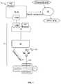
- FIG. 1is a surgical procedure setup depicting the components of a surgical planning, assessment, and correction system, according to one embodiment
- FIG. 2is a perspective view of one embodiment of a digitizer array in the closed position comprising part of the system of FIG. 1 ;
- FIG. 3is an exploded perspective view of the digitizer array of FIG. 2 ;
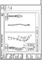
- FIG. 4is a perspective view of the digitizer array of FIG. 2 in the open position
- FIG. 5is a front view of one embodiment of a digitizer pointer assembly comprising part of the system of FIG. 1 ;
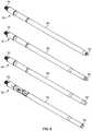
- FIG. 6is a perspective view of various surgical pointers compatible with the digitizer array of FIG. 2 ;
- FIG. 7is a perspective view of the spatial tracking algorithm according to one embodiment
- FIG. 8is a flowchart depicting the rod bending workflow according to one embodiment
- FIG. 9is a flowchart depicting the steps in generating a rod solution according to a first embodiment
- FIG. 10is a flowchart depicting the steps in generating a rod solution according to a second embodiment
- FIG. 11a flowchart depicting the steps in generating a rod solution according to a third embodiment
- FIG. 12is a flowchart depicting the steps of the rod bending process according to a first embodiment
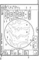
- FIG. 13is a screen shot depicting an example setup screen of the system of FIG. 1 ;
- FIG. 14is a screen shot depicting an example IR positioning sensor setup screen of the system of FIG. 1 ;
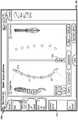
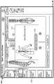
- FIG. 15is a screen shot depicting an example screw location digitization screen during a first step in the Acquire Screws step of FIG. 12 ;
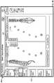
- FIG. 16is a screen shot depicting an example screw location digitization screen during a second step in the Acquire Screws step of FIG. 12 ;
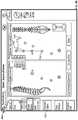
- FIG. 17is a screen shot depicting an example screw digitization screen during a third step in the Acquire Screws step of FIG. 12 ;
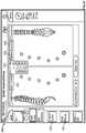
- FIG. 18is a screen shot depicting an example rod stress map screen of the system of FIG. 1 ;
- FIG. 19is a screen shot depicting an example bend instructions screen in the Bend Instructions step of FIG. 12 ;
- FIG. 20is a flowchart depicting the steps of the rod bending process according to a second embodiment
- FIG. 21is a screen shot depicting an example Advanced Options menu screen of the system of FIG. 1 ;
- FIG. 22is a screen shot illustrating a first example screen of an Adjust Points feature according to one embodiment
- FIG. 23is a screen shot illustrating a second example screen of the Adjust Points feature of FIG. 22 ;
- FIG. 24is a screen shot illustrating a third example screen of the Adjust Points feature of FIG. 23 ;
- FIG. 25is a screen shot illustrating a first example screen of a Pre-Bent Preview feature according to one embodiment
- FIG. 26is a screen shot illustrating a second example screen of the Pre-Bent Preview feature of FIG. 25 ;
- FIG. 27is a screen shot illustrating a third example screen of the Pre-Bent Preview feature of FIG. 25 ;
- FIG. 28is a screen shot illustrating a first example screen of a Sagittal Correction feature according to one embodiment
- FIG. 29is a screen shot illustrating a second example screen of the Sagittal Correction feature according to the embodiment of FIG. 28 ;
- FIG. 30is a screen shot illustrating a first example screen of the Sagittal Correction feature according to a second embodiment
- FIG. 31is a screen shot illustrating a second example screen of the Sagittal Correction feature according to the embodiment of FIG. 30 ;
- FIG. 32is a screen shot illustrating a third example screen of the Sagittal Correction feature according to the embodiment of FIG. 30 ;
- FIG. 33is a screen shot illustrating an example screen of the Sagittal Correction feature according to a third embodiment
- FIG. 34is a screen shot illustrating an additional example screen of the Sagittal Correction feature according to the embodiment of FIG. 28 and/or FIG. 33 ;
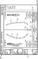
- FIG. 35is a screen shot illustrating a first example screen of the Coronal Correction feature according to a first embodiment
- FIG. 36is a screen shot illustrating a second example screen of the Coronal Correction feature according to the embodiment of FIG. 35 ;
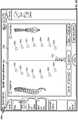
- FIG. 37is a screen shot illustrating a first example screen of the Coronal Correction feature according to a second embodiment
- FIG. 38is a screen shot illustrating a second example screen of the Coronal Correction feature according to the embodiment of FIG. 37 ;
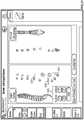
- FIG. 39is a screen shot illustrating a first example screen of the Coronal Correction feature according to a third embodiment
- FIG. 40is a screen shot illustrating a first example screen of the Coronal Correction feature according to a fourth embodiment
- FIG. 41is a screen shot illustrating a second example screen of the Coronal Correction feature according to embodiment of FIG. 40 ;
- FIG. 42is a screen shot illustrating a third example screen of the Coronal Correction feature according to the embodiment of FIG. 40 ;
- FIG. 43is a screen shot illustrating a fourth example screen of the Coronal Correction feature according to the embodiment of FIG. 40 ;
- FIG. 44is a screen shot illustrating a first example screen of the Coronal Correction feature according to a fifth embodiment
- FIG. 45is a screen shot illustrating a second example screen of the Coronal Correction feature according to the embodiment of FIG. 44 ;
- FIG. 46is a screen shot illustrating a third example screen of the Coronal Correction feature according to the embodiment of FIG. 44 ;
- FIG. 47is a screen shot illustrating a first example screen of the Coronal Correction feature according to a sixth embodiment
- FIG. 48is a screen shot illustrating a second example screen of the Coronal Correction feature according to the embodiment of FIG. 47 ;
- FIG. 49is a screen shot illustrating a third example screen of the Coronal Correction feature according to the embodiment of FIG. 47 ;
- FIG. 50is a screen shot illustrating a fourth example screen of the Coronal Correction feature according to the embodiment of FIG. 47 ;
- FIG. 51is a screen shot illustrating a fifth example screen of the Coronal Correction feature according to the embodiment of FIG. 47 ;
- FIG. 52is a screen shot illustrating an example screen of the Axial Correction feature according to one embodiment.
- FIG. 53is a perspective view of one embodiment of a mechanical rod bender comprising part of the system of FIG. 1 .
- a surgical planning, assessment, and correction system 10including a spatial tracking system 12 to obtain the location of one or more surgical implants 14 , a control unit 16 containing software to convert the implant locations to a series of bend instructions, and a bending device 18 to execute the bend instructions.
- the spatial tracking system 12includes an IR position sensor 20 , a digitizer pointer 23 , as well as other components including Host USB converter 21 .
- the spatial tracking system 12is in communication with control unit 16 .
- the control unit 16has spatial relation software and C-arm video import capabilities and is communicatively linked to the display 32 so that information relevant to the surgical procedure may be conveyed to the user in a meaningful manner.
- the relevant informationincludes, but is not limited to, spatial positioning data (e.g., translational data in the x, y, and z axes and orientation/rotational data R x , R y , and R z ) acquired by the IR position sensor 20 and intraoperative fluoroscopic images generated by a C-arm fluoroscope.
- spatial positioning datae.g., translational data in the x, y, and z axes and orientation/rotational data R x , R y , and R z
- the control unit 16includes a main display 32 and a processing unit, which collectively contain the essential processing capabilities for controlling the system 10 .
- the main display 32is preferably equipped with a graphical user interface (GUI) capable of graphically communicating information to the user and receiving instructions from the user.
- GUIgraphical user interface
- the processing unitcontains computer hardware and software that sends and receives digital and/or analog signals, process digital and/or analog signals, and displays the processed data to the user via the display.
- the primary functions of the software within the control unit 16include receiving user commands via the touch screen main display 32 , processing data according to defined algorithms, displaying received parameters and processed data, and monitoring system status.
- the main display 32may comprise a 15′′ LCD display equipped with suitable touch screen technology and the processing unit may comprise a 2 GHz processor.
- the processing unitmay further include a powered USB port, one or more media drives, a network port, a wireless network card, and a plurality of additional ports (e.g. USB, infrared, etc. . . . ) for attaching additional accessories, sensors, and external devices (e.g. printer, keyboard, mouse, etc.).
- the control unit 16sits near the surgical table but outside the surgical field.
- the system 10comprises a neuromonitoring system communicatively linked to the spatial tracking system 12 and/or the C-arm via the control unit 16 .
- the neuromonitoring systemmay be the neuromonitoring system shown and described in U.S. Pat. No. 8,255,045, entitled “Neurophysiologic Monitoring System” and filed on Apr. 3, 2008, the entire contents of which are hereby incorporated by reference as if set forth fully herein.
- FIGS. 2-6depict the various components of one or more digitizer pointers 23 for use with the present invention.
- FIGS. 2-4detail an example IR-reflective tracking array 22 component of the digitizer pointer 23 .
- Array 22includes a housing 34 , bilateral shutters 36 , and a plurality of IR-reflective spheres 38 arranged in a calculated manner at various locations on the array 22 such that their position information is selectively detectable by the IR position sensor 20 .
- Housing 34comprises a top housing 40 , bottom housing 42 , and a distal threaded aperture 56 configured to threadably receive the threaded end 78 of a stylus (e.g., stylus 24 , 26 , 28 , and/or 30 ).
- a styluse.g., stylus 24 , 26 , 28 , and/or 30 .
- Top housing portion 40is further comprised of upper portion 44 , underside 46 , and sides 48 .
- a plurality of sphere apertures 52extend between upper portion 44 and underside 46 and are sized and dimensioned to receive reflective spheres 38 within recessed pockets 54 .
- Each side 48includes cutout 50 sized and dimensioned to receive tongue 70 .
- Bottom housing 42is comprised of a first face 58 and a second face 60 .
- the first face 58includes nesting platforms 62 and bullet posts 64 .
- Each shutter 36includes handle portion 66 , cover portion 68 , tongue 70 , interdigitating gear teeth 72 , and channel 74 for receiving bullet posts 64 .
- a spring 76extends between the two shutters 36 and is held in place via spring posts 71 .
- each IR-reflective sphere 38is nested on a platform 62 .
- Top housing 40is placed over bottom housing 42 in a snap fit configuration such that each IR-reflective sphere 38 fits within a recessed pocket 54 within its respective sphere aperture 52 .
- bilateral shutters 36are positioned over the housing 34 with tongues 70 sliding into cutouts 50 such that each shutter cover 68 obscures exactly one half of the IR-reflective sphere 38 (for example, the middle IR-reflective sphere 38 ) as depicted in FIG. 2 .
- the IR-reflective tracking array 22mates with one or more surgical objects (for example styluses 24 , 26 , 28 , 30 ).
- Each stylus 24 , 26 , 28 , 30includes a threaded proximal end 78 for mating with the threaded distal aperture 56 of the IR-reflective tracking array 22 , elongate shaft 80 , and shaped distal tip 82 .
- Shaped distal tip 82may be any shape that is complimentary to, and fits securely within, the shape of a particular screw head. For example, FIG.
- FIG. 6shows styluses 24 , 26 , 28 , and 30 each with a different shaped distal tip designed to mate with different open screw systems and minimally-invasive screw systems.
- the distal tip 82is preferably inserted into each screw while orienting the digitizer pointer coaxial to that screw (or other fixation device).
- the digitizer pointer 23may be used to acquire positional information about some or all screw locations.
- the shaped distal tip 82is coaxially aligned into the screw head and the array 22 is triggered to register the screw point.
- Screw locationsmay be digitized in a superior-inferior or inferior-superior direction.
- the first screw location digitizedcorrelates to the rod insertion direction component of the bend instructions (described below).
- Squeezing handles 66activates the spring mechanism and permits the shutters 36 to open equally via the interdigitating gear teeth 72 ( FIG. 4 ).
- Opening the shutter covers 68exposes the middle IR-reflective sphere 38 and allows the IR tracking array 22 to be “seen” by the IR position sensor 20 and the position of the digitizer pointer 23 to be digitized. In this way, the IR position sensor 20 only recognizes the digitizer pointer 23 once the middle sphere 38 is exposed which allows for point-by-point tracking and obviates the sensing and digitization of one or more unnecessary data points which may occur with prior art systems that continually track surgical objects. Further, use of the gear mechanism allows the passive IR-reflective sphere 38 to be “seen” symmetrically by the IR position sensor 20 , thereby enabling a more accurate calculation of position information by the system 10 .
- control unit 16emits an audible sound to notify the user that the middle sphere 38 is recognized by the IR position sensor 20 and the screw point is acquired. Once a point has been registered, the shutter handles 66 may be released, thereby closing the bilateral shutters 36 . This process is then repeated for all screw locations to be digitized.
- the spatial tracking system 12measures the six degrees of freedom (6 DOF) information for the tracked IR-reflective spheres 38 . These data provide the full pose (position and orientation) of each screw of interest which may then be made available to the algorithm library to calculate the bend instructions.
- the surgical bending softwaretakes the location and direction data of the screw locations and uses one or more geometry-based algorithms to convert these relative screw locations into a series of bend instructions.
- the surgical bending algorithmsmay be divided into two smaller sub-systems: (1) the spatial location algorithms that acquire, collect, and digitize points in space and (2) the bending algorithms that analyze the points and calculate the bend instructions and rod length needed to bend a rod with the mechanical bending device 18 .
- the spatial tracking system 12measures the six degrees of freedom (6 DOF) information for the tracked IR-reflective spheres 38 . These data provide the full pose (position and orientation) of each screw of interest which may then be made available to the algorithm library to calculate the bend instructions.
- FIG. 7is a flow chart indicating the steps of the spatial location data acquisition process according to one embodiment.
- the system 10initializes the sensor objects from configuration to connect to, control, and read data from the IR position sensor 20 (step 140 ).
- the system 10inspects all devices connected to it and finds the device with a device ID that corresponds to the IR position sensor 20 (step 141 ).
- step 142if an IR position sensor 20 is found at step 141 , the system 10 continues to establish a connection with the IR position sensor 20 (step 143 ). However, if not the system 10 continues to search. After the system 10 connects to the IR sensor 20 , it then loads a tool file that defines the array 22 (step 144 ). After initialization and tool file loading, the IR sensor 20 must prepare for taking data. At step 145 , the IR sensor 20 is enabled and ready to generate positional data but is left idle until tracking is enabled. By way of example and as described with reference to FIG. 14 , selecting the position of the IR sensor 20 with respect to the patient's body causes the control unit 16 to send the IR sensor 20 a command to begin tracking.
- the IR sensor 20may be polled to for data (step 147 ).
- new datais requested twenty times per second from the IR sensor 20 .
- the data generated from polling the IR sensor 20is checked to ensure that it is reporting valid data. The data may be considered valid if all of the IR-reflective spheres 38 are visible to the IR sensor 20 , the digitizer pointer 23 is fully inside the IR sensor's 20 working volume, there is no interference between the IR sensor 20 and the digitizer pointer 23 , and both the location and rotation information reported are not null.
- step 149if the data is not deemed valid, then the digitized point is not used by the system 10 and polling is resumed. If the fifth IR-reflective sphere 38 (i.e. the middle sphere) is visible on the digitizer pointer 23 (step 150 ), the process of collecting positional data for the bend algorithm commences. If the middle sphere 38 is not visible, then the data is available to the system 10 only to show proximity of the IR sensor 20 and IR-reflective tracking array 22 (step 151 ). Points used by the bend algorithm are preferably an average of several raw elements (step 152 ). Normally, five points are collected at this step before the points are processed and made available to the bend algorithm. The position data is averaged using a mean calculation.
- the directionsare averaged in the quaternion representation (raw form) then converted to a unit direction vector.
- the datais rotated from the spatial tracking system 12 coordinate from into the system 10 coordinate frame using a rotation matrix.
- the datais available for the bend algorithm to collect and process further as will be described in greater detail below.
- the surgical bending softwaretakes the location and direction data of the screw locations as described above and uses one or more geometry-based algorithms to convert these relative screw locations into a series of bend instructions.
- FIG. 8is a flow chart indicating the steps of the surgical bending process according to a first embodiment.
- the system 10may validate the system inputs to ensure the rod overhang is greater than zero, validate the sensor setup to ensure that the IR sensor 20 location has been set, and validate each of the acquired points.
- the validation of each of the acquired pointsensures, for example, that there are at least two screw points digitized, no two screw locations are too far apart, no two screw locations are too close together, and the span between the superior-most and inferior-most screw locations is not longer than the longest available rod.
- the datamay be centered and aligned such that the first data point acquired is set at the system 10 coordinate's origin and all data is aligned to the x-axis of the system's coordinates thereby reducing any potential misalignment of the IR sensor 20 relative to the patient's spine.
- the system 10may perform rod calculations for a straight rod solution, a pre-bent rod solution, and a custom-bend solution.
- a straight rod solutionthe system 10 first determines the length of a straight rod that will span all of the screw locations. This length may be calculated to accommodate each of the screw heads, hex and nose lengths of the rods chosen, and the user's selected rod overhang length.
- the system 10fits the data to a straight line, if the screw data is within tolerance of the straight line, then the bend instructions will return a straight rod, otherwise it will return no rod solution and proceed to look for a pre-bent rod solution.
- the tolerancemay be 2 mm in each of the sagittal and coronal planes.
- the system 10For a pre-bent rod solution, the system 10 first determines the length of the shortest pre-bent rod from the available rod from the available rods (as will be described in greater detail below) that will span all of the screw locations. This length may be calculated to accommodate each of the screw heads, hex and nose lengths of the rods chosen, and the user's selected rod overhang length. Next, the system 10 fits the digitized screw data to a circular arc in 3-dimensional space. If the screw data is within the tolerance of the arc, then the bend instructions will return a pre-bent rod solution, otherwise it will return no rod solution and proceed to look for a custom-bend rod solution. By way of example, this tolerance may be 2 mm in each of the sagittal and coronal planes.
- FIG. 9depicts a flow chart of a custom bend algorithm according to one embodiment.
- screw location and direction datais generated by the spatial tracking system 12 as set forth above. The data is then projected into two planes: the x-y plane (coronal view) and the x-z plane (sagittal view). Each projection is then handled as a 2D data set.
- a fixed size loopis generated over small incremental offsets for the first bend location for the end of the rod which optimizes the ability of the bend reduction step 162 to make smooth solutions.
- the system 10creates a spline node at each screw location and makes a piecewise continuous 4 th order polynomial curve (cubic spline) through the screw points.
- the smooth, continuous splineis sampled at a regular interval (e.g., every 1 cm) along the curve to generate an initial set of proposed bend locations.
- a regular intervale.g., every 1 cm
- as many bends as possibleare removed from the initial set of proposed bend locations from step 161 as possible to reduce the number of bends the user must execute on a rod in order to fit it into a screw at each digitized screw point.
- no bendis removed if eliminating it would: (1) cause the path of the bent rod to deviate more than a predefined tolerance limit; (2) cause any of the bend angles to exceed the maximum desired bend angle; and (3) cause the rod-to-screw intersection angle to exceed the maximum angulation of the screw head.
- the 2D data setsare combined and handled as a 3D data set.
- the 3D line segmentsare then evaluated based on distance between each line segment interaction (Location), the angle between two line segments (Bend Angle), and the rotation (Rotation) needed to orient the bend into the next bend plane using the following calculations: (( X 2 ⁇ X 1 ) 2 +( Y 2 ⁇ Y 1 ) 2 +( Z 2 ⁇ Z 1 ) 2 ) 1/2
- the loopis completed (step 163 ).
- the system 10may output the rod solution having the smallest maximum bend angle (i.e., the smoothest bent rod). It is to be appreciated that the system 10 may choose the rod solution displayed based on any number of other criteria.
- the system 10then generates the three-dimensional locations of the bends in space.
- the system 10generates instructions for the user to choose a straight rod, a pre-bent rod, or to custom bend a rod (step 157 ). All of the output instructions are human-readable strings or characters. In all cases, the length of the required rod is calculated as described above and is displayed to the user as either a cut rod or standard rod. For custom bend solutions, rods are loaded into the bender with the “inserter end” (e.g., one pre-determined end of the rod) into the bender collet 126 .
- the instructionsare flipped, and the cut (or nose) end of the rod is instructed to be put into the bender collet 126 .
- the bend instructionsare generated from the geometric bend locations and are given as “Location”, “Rotation”, and “Bend” values as will be described in greater detail below. These values correspond to marks on the mechanical bender 18 .
- FIGS. 10-11depict a flow chart of a second embodiment of a custom bend algorithm.
- the custom bend algorithmincludes a virtual bender used to render a virtual rod.
- the following calculations and the flowcharts of FIGS. 10-11highlight the steps of this embodiment.
- a virtual bender (B)consists of a mandrel (M) of radius M r (mm).
- Mmandrel
- M rradius
- the key assumption when bending the virtual rod around Mis the conservation of arc length.
- the virtual rod, Ris bent according to a list of instructions.
- Each instructionconsists of a location (I l ), rotation (I r ), and bend angle (I ⁇ ).
- the locationis the position of the rod in the bender and corresponds to the point directly under the mandrel M.
- the rotationis given in degrees (0°-360°) and corresponds to the amount the rod is rotated from 0 in the collet.
- the bend angleis given by a single letter that corresponds to a specific angle in degrees. There is a corresponding notch on the bender with the same letter for the user to select.
- i0 N r ⁇ 1 which effectively orients the virtual rod to be at zero rotation in the virtual bender.
- the system 10rotates the virtual rod around the x-axis by I r (step 168 ).
- the system 10finds the point ⁇ circumflex over (r) ⁇ i that matches I l .
- the virtual rodis translated by ⁇ circumflex over (r) ⁇ i .
- each rod point from i to i+M r *I ⁇is projected onto the mandrel M while preserving segment length (step 169 - 170 ).
- the virtual rodis then rotated around the x-axis by angle ⁇ I r .
- the next stepis to align the bent virtual rod to the acquired screw positions (step 172 ).
- the alignment processhas two stages—first, the system 100 finds the optimum rotation coarse scale (step 174 ). Second, the system performs the iterative closest point iteration algorithm fine scale.
- the systemfirst initializes the result close to a global minimum (step 173 ).
- this initializationfollows the approach described below:
- step 175the proposed solution may not be the global minimum. Thus, the following are repeated until convergence (step 175 ):
- Verify the erroris reduced (step 179 ).
- the virtual rodis rendered at step 180 .
- 0, then the middle point of the triad (in this case r 1 ) is redundant, provides no new information to the geometry of the rod and may be removed.
- the virtual bendermay be capable of bending a rod at any location of any angle perfectly to observe arc length.
- Using a virtually bent 3D rod to determine problem screwsi.e. screw locations with a high screw-rod fit error
- a Markov chainis a sequence of random variables, X 0 , X 1 . . . , such that the current state, the future and past states are independent.
- the search of the bender spaceis quite complex as there are several constraints that must be observed for the algorithm to produce valid bend instructions (e.g., the bend locations cannot be in close proximity to the screws, the bend locations must be in multiples of 5 mm apart, the bend angles must be in multiples of 5°, no bend angle can be greater than 60°, etc.).
- the likelihood or error functionmay be constructed based on how well the virtual rod fits the data.
- the rodis fit to the data in the least squares sense.
- a likelihood functionis defined that incorporates, for example, a prior to prefer fewer bend instructions:
- Equation (3)there has been introduced a prior to control the number of bends introduced into the rod.
- This probabilistic approach to bend instruction generationallows for tailoring of constraints, for instance, a prior on the severity of the bends could also be introduced. Further, a prior could be introduced on how to define how close to the screws the bends may be located. This prior may have a “preferred” value, but probabilistically, there may be an optimal solution away from this idealized value.
- some hypothesized rules that may be applied to this algorithminclude, but are not limited to: birth move: add a bend to the current solution; death move; remove a bend from the current solution; update move: translate rod points along the rod. Use of this embodiment may provide more potential rod solutions to the user.
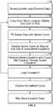
- the system 10is typically utilized at the end of a posterior or lateral fixation surgical procedure after screws, hooks or other instrumentation have been placed, but prior to rod insertion.
- the system 10obtains position information of the implanted screw positions and outputs bend instructions for a rod shaped to custom-fit within those implanted screws.
- pertinent informationis inputted into the system via a setup screen.
- the userdesignates the side for which a rod will be created (patient's left or right side).
- the system 10digitizes the screw locations.
- the system 10outputs bend instructions.
- the userbends the rod according to the bend instructions. Steps 190 - 198 may then be repeated for a rod on the contralateral side of the patient if desired.
- FIG. 13illustrates, by way of example only, one embodiment of a screen display 200 of the control unit 16 capable of receiving input from a user in addition to communicating feedback information to the user.
- a graphical user interfaceGUI
- the screen display 200may contain a header bar 202 , a navigation column 204 , device column 206 , and a message bar 208 .
- Header bar 202may allow the user to view the date and time, alter settings, adjust the system volume, and obtain help information via date and time display 210 , settings menu 212 , volume menu 214 , and help menu 216 respectively. Selecting the settings drop-down menu 212 allows the user to navigate to system, history, and shutdown buttons (not shown). For example, choosing the system button displays the rod bending software version and rod bender configuration file; choosing the shutdown option shuts down the rod bending software application as well as any other software application residing on the control unit 16 (e.g. a neuromonitoring software application); and choosing the history option allows the user to navigate to historical bend points/instruction data in previous system sessions as will be described in greater detail below.
- system buttondisplays the rod bending software version and rod bender configuration file
- choosing the shutdown optionshuts down the rod bending software application as well as any other software application residing on the control unit 16 (e.g. a neuromonitoring software application)
- choosing the history optionallows the user to navigate to historical bend points/in
- navigation column 204contains various buttons (e.g., buttons 218 , 220 , 222 , 224 , 226 ) for navigation through various steps in the rod bending process. Pressing button 204 expands/minimizes the details of the navigation column.
- Devices column 206contains various buttons indicating the status of one or more devices associated with the system 10 . By way of example, devices column 206 may include buttons 228 and 230 for the digitizer 23 and IR sensor 20 components of the system 10 , respectively. Pressing button 206 expands/minimizes the details of the devices column.
- pop-up message bar 208communicates instructions, alerts, and system errors to the user.
- FIGS. 13-14depict an example setup screen.
- the system 10Upon selecting setup button 218 on the display screen 200 , the system 10 automatically initiates the setup procedure.
- the system 10is configured to detect the connection status of each of its required components.
- icons 228 , 230indicate the connectivity and activity status of the digitizer 23 and IR sensor 20 , respectively. If one or more required components are not connected or are connected improperly, the display 200 may alert the user to address the issue before proceeding via textual, audio, and/or visual means (e.g., textual messages, audible tones, colored icons or screens, blinking icons or screens, etc.).
- the digitizer icon 228is a status indicator for the active acquisition and/or recognition of the digitizer and the presence and background color of the icon 228 may change to indicate the digitizer tracking status.
- the icon 228may be absent when the system 10 is not acquiring screws and does not recognize the digitizer, gray when the system 10 is not acquiring screws and recognizes the digitizer, green when the system 10 is in screw acquisition mode and recognizes the digitizer, and red when the system 10 is in screw acquisition mode and does not recognize the digitizer. Pressing button 206 expands/minimizes the details of the device column 206 .
- pressing icon 228expands a pull-out window for the different stylus options available with the system 10 (e.g., styluses 22 , 24 , 26 , 30 as described above).
- the IR sensor graphic icon 230is a status indicator for the IR sensor 20 . The presence and background color of the icon 230 may change to indicate the status of the IR sensor 20 .
- the icon 230may be absent when the system 10 does not recognize the IR sensor 20 , gray when the system 10 recognizes the IR sensor 20 is connected to the system 10 , and red when the system 10 senses a communication or bump error for the IR sensor 20 .
- the IR sensor 20should be recognized if it is connected after initialization of the bending application.
- the usermay then input one or more pieces of case-specific information from one or more drop-down menus.
- drop-down menus for rod system 234 , rod material/diameter 236 , rod overhang 238 , procedure type (not shown), and anatomical spinal levels of the surgical proceduremay be accessed from the setup selection panel 232 of the screen display 200 .
- the rod system drop-down menu 234allows the user to choose the rod system he/she plans to use.
- This selectiondrives choices for the rod material/diameter 236 drop-down menus.
- the system 10may be programmed with numerous fixation options from one or more manufacturers. Alternatively, it may be programmed with the fixation system selections for one manufacturer only (e.g. NuVasive® Precept®, Armada®, and SpherX® EXT). The user may also choose the combination of rod material (e.g. titanium, cobalt chrome, etc.) and rod diameter (e.g. 6.5 mm diameter, 5.5 mm diameter, 3.5 mm diameter, etc.).
- the drop-down menu 238 for material and diameter optionsmay preferably be dependent upon the choice of rod system.
- the system 10contains functionality for accommodating multiple rod diameters and transitional rods as well as side loading and top loading occipital plates as used, for example in Occipital-Cervical-Thoracic (OCT) fusion procedures.
- OCTOccipital-Cervical-Thoracic
- the system 10aids the user in setting up the IR sensor 20 in an optimal position for positional data acquisition.
- any visual (textual, graphic) indicatormay be used to indicate the IR sensor placement instructions.
- an active graphicdirects the user to position the IR sensor 20 relative to the digitizer array 22 held static within the patient's body. As shown in FIG. 14 , the user first selects the side of the patient the IR sensor 20 is located on by selecting the left side sensor position button 242 or right side sensor position button 244 in the IR sensor setup panel 240 .
- Choosing the left or right side sensor position button 242 , 244activates a the IR sensor positioning panel 246 such that sensor graphic 248 and a tracking volume box graphic 250 appear on the display screen 200 .
- Tracking volume box 252that moves with the sensor graphic 248 as the IR sensor 20 is moved.
- the userpositions the digitizer array 22 into the body of the patient. Once recognized by the system 10 , a target volume box 252 (which may be displayed as white in color) is positioned over the patient graphic 254 .
- the usermoves the IR sensor 20 relative to the digitizer array 22 until the tracking volume box 250 matches up to the position of the target volume box 252 .
- the sensor graphic 248increases in size if it is moved superior to the target tracking volume and decreases in size if it is moved inferior to the target volume.
- the tracking volume box 250may be color-coded to depict the relative distance to the target volume. By way of example, the tracking volume box 250 may be depicted in red if the distance to the target volume is outside of a certain distance in one or more axes (e.g., outside ⁇ 8 cm in all 3 axes) and green if within or equal to ⁇ 8 cm in all 3 axes.
- a graphic(e.g., a check) may appear on setup button 218 to indicate such a completion and the system 10 proceeds to step 192 in the flowchart of FIG. 12 .
- the userdesignates which side of the patient's spine to acquire digitized positional information from by selecting either the Left “L” toggle/status button 220 or Right “R” toggle/status button 222 .
- the userselects the Acquire Screws button 224 which navigates the display screen 200 to an Acquire Screws (left or right) screen shown by way of example in FIGS. 15-17 .
- the display screen 200includes a sagittal view panel 256 and a coronal view panel 258 with spine graphics 260 , 262 in each of the sagittal and coronal views, respectively.
- Spine graphic 260may flip orientation depending on which side of the spine the user is digitizing (left or right).
- spine graphic 262may highlight the side of the patient the user is digitizing (left or right). The user may digitize the location of each implanted screw using, by way of example, the digitizer pointer 23 as described above.
- each screw point 264is digitized, its relative location with respect to the other acquired screw points 264 can be viewed in both sagittal and coronal views via the sagittal view panel 256 and the coronal view panel 258 as shown in FIG. 16 .
- the last screw point digitizedmay have a different graphic 266 than the previously-acquired screw points 264 (by way of example, the last screw point acquired 266 may be a halo and the previously-acquired screw points 264 may be circles).
- the screws locationsmay be digitized from a superior-to-inferior or inferior-to-superior direction and according to some embodiments, the system 10 can detect which direction the digitization is occurring in after the acquisition of two consecutive screw point locations.
- the userwishes to delete a digitized screw point, he/she may do so by pressing the “Clear Point” button 270 . If the user wishes to delete all digitized screw points, he/she may do so by pressing the “Clear All Points” button 268 .
- the usermay press the “Calculate Rod” button 272 which initiates the curve calculation preferably using one of the algorithms discussed above.
- a rod graphic 274populates through the screw points 264 , 266 and a confirmation graphic (e.g., a check) may appear on the “Acquire Screws” button 224 to indicate that the system 10 has generated a rod solution.
- the “Calculate Rod” button 272becomes the “Undo Rod” button 272 . If the user presses the “Undo Rod” button 272 , the rod solution 274 is cleared and the user may acquire more screw points or clear one or more screw points. After the “Undo Rod” button 272 is pressed, it then changes back to the “Calculate Rod” button 272 .
- the system 10may include one more indicators to the user as to the nature of the bend calculation.
- the system 10may include a visual graphic for where along a proposed rod the curve calculation is generating a severe bend (acute angle).
- the system 10may include a visual graphic of the location of one or more stress risers on the proposed rod. In one implementation, this visual graphic is a color-coded stress map.
- the system 10may calculate these stress risers of the material properties of the rod and the bend geometries of the proposed rod. These stresses may be communicated to the user via a color gradient indicating the amount of stress. This color code may be used to inform the user that a proposed rod solution is reaching a higher-risk stress point based on the degree of bend placed on the rod.
- a usermay select the Stress Map feature via a “Stress Map” button on display screen 200 .
- Selecting the Stress Map buttonmaps the stresses onto the proposed rod solution as depicted in FIG. 18 .
- FIG. 18shows three colored areas indicating potential stress risers on the rod. Selecting the Rod preview button returns the display screen back to the previous function.
- the usermay select “Undo Rod” button 272 , perform one or more surgical maneuvers (e.g. reduce the screw, backup the screw, adjust the screw head, etc.), redigitize the screw point, and generate a more feasible solution (e.g. a rod with a less-severe bend or with fewer stress risers).
- the Screw Acquisition step 194is complete and the system 10 proceeds the Bend Instructions step 196 in the flowchart of FIG. 12 .
- the system 10may display the offending point resulting in the severe bend angle in red and offer the next-best solution that includes a bend angle falling within a pre-determined range of angles for that bender.
- the Screw Acquisition step 194is complete and the system 10 proceeds the Bend Instructions step 196 in the flowchart of FIG. 12 .
- the bend instructions within the bend instructions panel 276allows the user to view the bend instructions corresponding to the resulting rod solution in the Acquire Screws screen ( FIG. 17 ).
- the bend instructions panel 276contains three fields containing various aspects of the bending instruction: upper message field 278 , bender instructions field 280 , and lower message field 282 .
- the upper message field 278may communicate the rod cut length, rod type, and/or rod loading instructions to the user (e.g. “Cut Rod: 175.00 mm Load Inserter End Into Bender”).
- the bender instructions field 280displays rows 284 of bend maneuvers in location 286 , rotation 288 , and bend angle 290 to perform on the mechanical bender 18 as will be described in greater detail below. In the example shown in FIG. 19 , there are five rows indicating five bend instructions.
- the lower message field 282may communicate the direction of insertion or orientation of implanting the rod to the user. For example, the lower message field 282 shown in FIG. 19 provides the following sample instruction: “Insert Rod head to foot.” In some implementations, the rod insertion direction into the patient is dependent on the sequence of screw digitization (superior-to-inferior or inferior-to superior).
- the bend instruction algorithmtakes into account the orientation of the inferior, superior, anterior, and posterior aspects of the rod and ensures that these aspects are known to the user.
- the system 10manages which bends are imparted on the rod first based on the severity of the bend angles. The section of the bend instructions with greater bend angles may be performed first then the straighter bend sections of the bend instructions may be performed last. Further, the instructions may also direct the user to align a laser line or orientation line on the rod to an alignment arrow (not shown) on the mechanical rod bender 18 . This alignment controls the Anterior/Posterior orientation of the rod geometry and generates bend instructions accordingly.
- the userfollows the bend instructions generated by the system 10 for location (location may be color-coded on the bender 18 and on the screen 200 as green triangle), rotation (rotation may be color-coded on the bender 18 and on the screen 200 as red circle), and bend angle (bend angle may be color-coded on the bender 18 and on the screen 200 as blue square), sequentially, starting at the first bend instruction and working sequentially until the final bend is completed. From here, the user may repeat steps 190 - 198 on the rod construct for the contralateral side of the patient's spine.
- a usermay wish to toggle between left and right screens to view left and right digitized screw points, rod previews, and bend instructions for reference or comparison. Selecting the Left “L” toggle/status button 220 and right “R” toggle/status button 222 allows the user to do so.
- the GUImay additionally include a History feature. Selecting the History button (not shown) will allow the user to refer back to any previous rod bending solution.
- the usernavigates to the Bend Instructions screen 226 based on choice of the L/R toggle buttons 220 , 222 and pressing Bend Instruction button 226 . If navigating to previous bend instructions, the Bend Instructions screen will display previous bend instructions. Once the user has selected the desired rod solution, the user then executes the bends using the mechanical bender 18 .
- the system 10obtains position information of the implanted screws (steps 192 and 194 ), accepts correction inputs via one or more advanced options features (step 195 ), and generates for viewing bend instructions for a rod shaped to fit at locations apart from those implanted screw positions (step 196 ) as depicted in the flowchart of FIG. 20 . Installing a rod shaped in this manner could correct a curvature or deformity in the patient's spine according to a user's prescribed surgical plan. Details of the system 10 are discussed now discussed with examples for obtaining a rod bent according to one or more surgical plans.
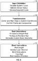
- selecting the “Advanced Options” button 292expands an Advanced Options menu 292 from which the user may perform one or more corrections to the digitized screw points and the system 10 generates bend instructions that will achieve those desired corrections on the patient's spine once the rod is implanted and the screws are brought to the rod.
- a usermay wish that the rod bend solution will consider a point that is not a digitized screw point in determining the bend instructions. According to some implementations, this point is an adjusted distance from the digitized screw point location. Selecting the “Adjust Points” button 296 from the Advanced Options menu 292 navigates the user to an Adjust Points screen as depicted in FIG. 21 . Selecting a digitized screw location of interest (for example the screw point represented as dot 304 in FIG. 22 ) highlights the screw point and brings up an adjust points control 306 in each of the sagittal and coronal views 256 , 258 .
- dot 304changes color based on the distance from the originally digitized screw location as shown in FIG. 23 .
- that colorcorresponds to color-coded offset distance indicator 322 which provides visual feedback to the user as to the distance the point has been adjusted.
- dot 304appears yellow in FIG. 23 indicating that the point has moved 4 mm in each of the sagittal and coronal planes.
- the system 10may have a maximum distance from the digitized point past which it will not allow the manipulated point to exceed (by way of example only, this distance may be 5 mm).
- the usermay adjust as many points as desired in this fashion.
- the usermay reset all adjusted points to their original configurations via “Reset” button 316 or may undo the last adjusted point via the “Undo Last” button 318 .
- the usermay either proceed to one or more additional advanced options as set forth below or select “Calculate Rod” 272 .
- “Calculate Rod” 272Once “Calculate Rod” 272 has been selected, the system 10 generates a rod in which the curve traverses the adjusted points, as in FIG. 24 , thereby creating a correction-specific rod and providing the user with the ability to correct the curvature or deformity in the spine according to his or her prescribed curve.
- a usermay wish for a smoother rod bend.
- the “Virtual Point” button 320shown by way of example in FIG. 23
- the system 10allows the user to add an additional point anywhere in between the superior-most and inferior-most digitized screw locations. While there is no screw at this location, this point is taken into consideration during the curve calculation and may coerce the curve into a more natural shape yielding a smoother rod bend.
- the usermay either proceed to one or more additional advanced options as set forth below or select “Calculate Rod” 272 and as described above, the system 10 generates a correction-specific rod solution 274 that the user may use to correct the spine to the shape of the rod.
- long rod constructsi.e. rods spanning multiple levels and/or regions of the spine
- passing a long rod that accommodates, for example, the kyphotic curvature of the thoracic spine as well as the lordotic curvature of the lumbar spine in such a fashionis quite challenging.
- the system 10allows the user to add one or more virtual offset connector points anywhere in between the superior-most and inferior-most digitized screw locations (preferably at the location between the kyphotic and lordotic curvatures of the thoracic and lumbar regions of the spine). Similar to the Virtual Point feature, these points are taken into consideration during the curve calculation and the rod solution generated will include two rods: a superior rod (e.g. a rod with a kyphotic curvature) and an inferior rod (e.g. a rod with a lordotic curvature) to be connected at the location or locations designated as virtual offset connector points.
- a superior rode.g. a rod with a kyphotic curvature
- an inferior rode.g. a rod with a lordotic curvature
- the usermay either proceed to one or more additional advanced options as set forth below or select “Calculate Rod” 272 and as described above, the system 10 generates a correction-specific rod solution 274 that the user may us to correct the spine to the shape of the rod.
- pre-bent rodit may be advantageous for some patient anatomies for a user to use a pre-bent rod.
- Use of a pre-bent rodeliminates the need for making additional bends to a rod while assuring that a desirable rod curve is achieved.
- selecting the “View Pre-Bent Rod” button 298 from the Advanced Options menu 292navigates the user to a “View Pre-Bent Rod” screen as depicted in FIGS. 25-27 .
- the system 10calculates and outputs the best pre-bent rod geometry based on the selected manufacturer's rod system that was chosen during the setup step 190 (e.g.
- a color-coded offset distance indicator 322may provide the user with an indication of the distance each screw position will be from the pre-bent rod construct.
- the system 10proceeds to the Bend Instructions step 196 which displays the corresponding pre-bent rod specifications in the Bend Instructions Screen ( FIG. 27 ).
- the upper message field 278instructs the user that, based on the digitized screw points, an 85.0 mm pre-bent rod is recommended. From here, the user may decide whether the patient's anatomical and surgical requirements would be better suited with a pre-bent option or a custom-bent option. Armed with the information from FIGS. 25-27 , the user may then adjust the screw positions to fit the pre-bent rod if needed (e.g., adjust the screw head, adjust the screw depth, etc.).
- a usermay want to align or correct the patient's spine in the sagittal plane (i.e., add or subtract lordosis or kyphosis).
- the system 10includes a sagittal correction feature in which the user is able to measure the amount of lordosis in the spine and adjust angles in the sagittal plane. The system 10 then incorporates these inputs into the bend algorithm such that the rod solution includes the desired alignment or correction.
- Selecting the “View Vectors” button 300 from the Advanced Options menu 292initiates the sagittal correction feature.
- the usermay select at least two points of interest and the system then determines the appropriate vector in the sagittal view. According to the embodiment shown in FIGS. 28, 29, and 34 the angles are measured and adjusted based on the screw trajectory screw axis position) using the digitized screw data acquired in the Acquire Screws step 194 .
- the userselects at least two screw points of interest (e.g., screw points 338 and 342 ).
- the system 10measures the angle between the screw trajectories (shown here as 35 degrees).
- the system 10may measure the total amount of lumbar lordosis by measuring the lumbar lordosis angle 334 in the superior lumbar spine (shown in FIG. 28 as 15 degrees) and the lumbar lordosis angle 336 in the inferior lumbar spine (show in FIG. 28 as 35 degrees).
- the angle adjustment buttons 328 , 330 on the Angle Adjustment Menu 326the user may increase or decrease the desired angle correction of the spine in the sagittal plane (i.e., add or subtract lordosis or kyphosis superiorly or inferiorly). As the angle is adjusted, the angular position 336 between the two screw points 338 , 342 is changed as well.
- the system 10may include a color-coded offset distance indicator 322 to provide the user with an indication of the distance each digitized screw position will be adjusted in the sagittal plane as described above.
- the usermay select the “Set” button 332 , and then the “Calculate Rod” button 270 .
- the system 10displays a rod solution 274 incorporating the user's clinical objective for correction of the spine in the sagittal plane as depicted in FIG. 34 .
- the system 10prompts the user to identify the superior end 327 , apex 329 and inferior ends 331 of the lumbar curvature and input the total lumbar lordosis (or kyphosis) of the desired curve of the rod using buttons 335 , 337 via box 333 . As depicted in FIG.
- FIG. 32indicates a calculated rod solution with the assigned 1/3-2/3 lumbar lordosis solution.
- the superior and inferior lumbar lordosis angles 334 , 336are measured, displayed, and adjusted referencing anatomy from an imported lateral radiographic image.
- lateral radiographic image 358may be inputted into the system 10 .
- the usermay touch the screen 200 and move lines 360 over at least two points of interest (e.g. the superior endplate of V1 and the inferior endplate of V3) and the system 10 then measures the angle between the two lines 360 .
- the usermay increase or decrease the desired angle correction of the spine in the sagittal plane (i.e., add or subtract lordosis or kyphosis superiorly or inferiorly).
- the amount of adjustmentis dynamically altered in its respective angle measurement box (i.e., either superior lumbar lordosis angle box 354 or inferior lumbar lordosis angle box 356 ).
- the useradjusts angle lines 360 as part of the inferior lumbar lordosis angle.
- the system 10measures this angle as 20 degrees as depicted in angle measurement field 350 .
- the userthen uses button 330 in superior angle adjustment menu 346 to increase the angle. This change is depicted in inferior lumbar lordosis angle box 356 .
- the usermay then press the capture angle button 352 and this parameter may be correlated to the digitized screw positions corresponding to the vertebral levels that those angles were measured off of.
- the system 10may include a color-coded offset distance indicator 322 to provide the user with an indication of the distance each digitized screw position will be adjusted in the sagittal plane as described above.
- the usermay select the “Set” button 332 , and then the “Calculate Rod” button 272 .
- the system 10displays a rod solution 274 incorporating the user's clinical objective for correction of the spine in the sagittal plane as depicted in FIG. 34 .
- the sagittal correction feature of the systemwill be able to account for any patient positioning-related deviations. It will also be appreciated that in addition to lordotic corrections, the sagittal angle assessment tool may be useful for other types of surgical maneuvers, including but not limited to pedicle subtraction osteotomy (PSO) procedures and anterior column reconstruction (ACR) procedures.
- PSOpedicle subtraction osteotomy
- ACRanterior column reconstruction
- a usermay want to align or correct the patient's spine in the coronal plane (i.e., correct scoliosis).
- the system 10includes one or more coronal correction features in which the user is able to view the patient's spine (and deformity) in the coronal plane via anterior-posterior x-rays; measure one or more anatomic reference angles; and/or persuade one or more screw locations towards a particular coronal alignment profile by manually or automatically biasing which direction the rod bend curve is adjusted.
- the system 10may then incorporates these inputs into the bend algorithm such that the rod solution includes the desired alignment or correction.
- Selecting the “Coronal Correction” button 302 from the Advanced Options menu 292initiates the coronal correction feature.
- the usermay wish to ascertain the degree of coronal deformity by referencing spinal anatomy, measuring the coronal Cobb angles between two anatomical references in the coronal plane, and adjusting those angles intraoperatively as part of the surgical plan to bring the spine into (or closer to) vertical alignment.
- the coronal Cobb anglesmay be ascertained using anterior-posterior radiographic images.
- Anterior-posterior radiographic image 358may be inputted into the system 10 .
- the coronal Cobb anglemay be determined by drawing lines parallel with the endplates of the most tilted vertebrae above and below the apex of the curve and measuring the angle between them. The user may touch the screen 200 and move lines 360 over at least two points of interest (e.g. the superior endplate of T11 and the inferior endplate of L3) and the system 10 then measures the angle between the two lines 360 .
- the usermay increase or decrease the desired angle correction of the spine in the coronal plane (i.e., add or subtract correction to make the endplates of the superior and inferior vertebrae selected more parallel with one another).
- the coronal Cobb angle measurementmay be dynamically altered in the coronal Cobb angle measurement box 350 .
- the starting coronal Cobb angleis 58 degrees.
- the useruses buttons 328 , 330 to reduce the angle lines 360 between T11 and L3.
- the usermay then press the capture angle button 352 .
- This parametermay be correlated to the digitized screw positions corresponding to the vertebral levels that those angles were measured off of.
- the system 10may include a color-coded offset distance indicator 322 to provide the user with an indication of the distance each digitized screw position will be adjusted in the coronal plane as described above (not shown here).
- the usermay select the “Set” button 332 , and then the “Calculate Rod” button 272 .
- the system 10displays a rod solution 274 incorporating the user's clinical objective for correction of the spine in the coronal plane.
- the coronal Cobb anglemay be displayed and adjusted referencing anatomy from digitized locations of screws placed in the left and right pedicles of the vertebrae of interest.
- the systemlinks left and right digitized screw locations for each respective vertebrae (line 361 ) and measures the angle between the two lines 361 (shown here in FIG. 37 as 58 degrees).
- the coronal Cobb anglemay be determined by selecting the screw location of the most tilted vertebrae above and below the apex of the curve. Using the angle adjustment buttons on the Angle Adjustment menu 326 , the user may increase or decrease the desired angle correction of the spine in the coronal plane (i.e.
- the Cobb angle measurementmay be dynamically altered as set forth above.
- the Cobb anglemay displayed alongside the radiographic image (shown in FIG. 37 with a starting coronal Cobb angle of 58 degrees).
- the useruses the buttons in menu 326 to reduce the angle lines 361 between T11 and L3.
- the desired amount of correctionshown, by way of example, in FIG. 38 as 0 degrees, the user may then press the “Set” button 332 and this parameter may be correlated to the digitized screw positions corresponding to the vertebral levels that those angles were measured off of.
- the system 10may include a color-coded offset distance indicator 322 to provide the user with an indication of the distance each digitized screw position will be adjusted in the coronal plane as described above (not shown here). Once the desired amount of angular correction is achieved, the user may select the “Calculate Rod” button 272 . The system 10 then displays a rod solution 274 incorporating the user's clinical objective for correction of the spine in the coronal plane.
- the system 10is configured to acquire digital position information of a plurality of screw locations, measure a baseline relationship between superior and inferior screw locations, and accept one or more user inputs to persuade one or more screw locations towards either a compressed or distracted alignment profile. The system 10 may then incorporate these inputs into the bend algorithm such that the rod solution includes the desired alignment or correction.
- Selecting the “Coronal Correction” button 302 from the Advanced Options menu 292initiates the coronal correction feature.
- the usermay wish to ascertain the degree of coronal deformity by referencing the distance between two digitized screw locations and adjusting the position of these digitized screw locations closer together (compression) or farther from one another (distraction) as part of the surgical plan to bring the spine into (or closer to) vertical alignment.
- the system 10links superior and inferior digitized screw locations for each respective vertebra and measures the height between the two screw locations.
- the usermay select the desired digitized screw locations 264 and increase or decrease inter-screw distance between the two. Doing so adds the desired correction of the spine (i.e. adds the desired compression or distraction) to make the digitized screw locations (and the pedicles the screws are implanted into) more aligned with one another in the coronal plane.
- the system 10may include a color-coded offset distance indicator 322 (not shown) to provide the user with an indication of the distance each digitized screw position will be adjusted in the coronal plane as described above (not shown here).
- the usermay select the “Set” button 332 , and then the “Calculate Rod” button 272 .
- the system 10displays a rod solution 274 incorporating the user's clinical objective for correction of the spine in the coronal plane.
- the usermay select at least two points of interest and the system then generates a best fit reference line through all points including and lying between the at least two points of interest.
- the ideal correction of the spine in the coronal planeis a straight vertical line extending between the superior-most and inferior-most screw locations of interest.
- the usermay wish to achieve a certain amount of correction relative to the ideal correction. From the display screen, the user may select a percentage of relative correction between the screw points as digitized (0% correction) and the best fit reference line (100%).
- the systemcalculates a rod solution and shows an off-center indicator 322 to provide a user with an indication of the distance each screw is from the coronally-adjusted rod construct as set forth above.
- the usermay straighten all points within the construct (global coronal correction).
- the superior and inferior screw points 362 , 364are selected and the system 10 generates a best fit global reference line 366 through all points 362 , 364 , 368 ( FIG. 40 ).
- the usermanipulates the + and ⁇ buttons 372 , 374 to adjust the percentage of correction desired.
- the amount of desired correctionis shown as 100% on the percentage correction indicator 376 , meaning the rod solution 274 will be a straight line in the coronal plane and all screw locations will be adjusted to fit the rod/line.
- the percentage correction indicator 376As depicted in FIG.
- the system 10may include a color-coded offset distance indicator 322 to provide the user with an indication of the distance each digitized screw position will be adjusted in the coronal plane as set forth above. If the user deems this an acceptable rod solution, the user selects the “Calculate Rod” button 272 to view the rod solution 274 ( FIG. 43 ) and receive bend instructions or proceeds to another advanced feature as will be described in greater detail below.
- the usermay straighten a subset of the screw points within the construct (segmental coronal correction). Based on the sequence those points are inputted into the system, a best-fit segmental reference line is generated through the points in the direction of the last chosen point. If an inferior point 364 is selected first and then a superior point 362 is selected second, the system 10 will draw the best-fit segmental reference line 378 superiorly as shown in FIG. 44 . Conversely, if a superior point 362 is selected first and then an inferior point 364 is selected second, the system 10 will draw the best-fit segmental reference line 378 inferiorly.
- the usermanipulates the + and ⁇ buttons 372 , 374 to adjust the percentage of correction desired.
- the amount of desired correctionis shown as 100% on the percentage correction indicator 376 , meaning the rod solution 274 will be a straight line in the coronal plane and all selected screw locations will be adjusted to fit the rod/line.
- unselected screw locations 380will not be adjusted to fit the rod/line and their relative locations will be inputted into the system 10 and taken into consideration when the rod calculation is made. As depicted in FIG.
- the system 10may include a color-coded offset distance indicator 322 to provide the user with an indication of the distance each digitized screw position will be adjusted in the coronal plane as set forth above. If the user deems this an acceptable rod solution, the user selects the “Calculate Rod” button 272 to view the rod solution 274 ( FIG. 46 ) and receive bend instructions or proceeds to another advanced feature as will be described in greater detail below.
- segmental coronal correctionmay be achieved relative to the patient's central sacral vertical line (CSVL) instead of a best-fit segmental reference line running through two selected digitized screw locations.
- CSVLis the vertical line passing through the center of the sacrum that may serves as the vertical reference line for the patient's coronal deformity as well as a guide for spinal correction in the coronal plane in accordance with the coronal assessment and correction features of the present disclosure.
- FIGS. 47-51illustrate a method for using the CSVL line for assessing coronal deformity and achieving coronal correction according to one embodiment.
- this methodcommences after all screws are implanted into the patient and digitized in the manner set forth above.
- the usergenerates one or more radiographic images of the sacrum, localizes a superior and inferior point on the sacrum, and marks those points (e.g., implants Caspar pins, marks the patient's skin with a marker, etc.).
- the userselects the “Alignment” button 506 ( FIG. 47 ).
- the useris prompted to digitize the marked skin points representing the superior and inferior sacral landmarks. As shown by way of example in FIG.
- box 510may pop up to instruct the user of the various steps of the workflow.
- the superior point on the sacrumhas already been digitized (shown as digitized point 512 ) and check mark 514 .
- Box 510further instructs the user to “Acquire Point at Inferior End.” Selecting “Clear Coronal Alignment Line” 516 to re-digitize the sacral points and/or exit out of the CSVL coronal correction feature.
- a dashed line 518representing the patient's true CSVL line appears on the screen ( FIG. 49 ) and the digitized screw locations 264 are reoriented in system 10 relative to the CSVL line 518 .
- the display 200 in the coronal viewnow represents the patient's current coronal curve relative to a vertical reference (CSVL).
- CSVLvertical reference
- the usermay select two points (i.e., the screw segment) he/she would like to correct or straighten relative to the CSVL.
- the userselects points 542 and 544 .
- the first point chosen 542is the point of rotation of the segment and the origin of the straightening line 520 .
- the second point 544determines the direction of the straightening line 520 .
- the straightening line 520may be drawn parallel to the CSVL line 518 as the objective of coronal correction is to make the spine as vertical as possible in the coronal plane.
- the userselects the “Calculate Rod” button 272 to view the rod solution 274 ( FIG. 51 ) and receive bend instructions.
- the usernow has a rod solution he/she can pull the screws to, knowing that it is straight relative to the CSVL line and therefore providing the desired correction of the coronal deformity.
- the userwill and receive bend instructions or proceeds to another advanced feature as will be described in greater detail below.
- a usermay want to align or correct the patient's spine in the axial plane (i.e., correct rotational deformity).
- the system 10includes one or more axial correction features in which the user is able to acquire digital position information of a plurality of screw locations, measure the amount of rotational deformity at each spinal level, and accept one or more user inputs to persuade one or more screw locations towards a de-rotated alignment profile. The system 10 then incorporates these inputs into the bend algorithm such that the rod solution includes the desired alignment or correction.
- Selecting the “Axial Correction” button (not shown) from the Advanced Options menu 292initiates the axial correction feature.
- the usermay wish to ascertain the degree of axial deformity by referencing the angle that is created between a line running through left and right pedicles relative to a horizontal reference (e.g. the floor when the patient is in the prone position). With this rotational angle known, the position of the digitized screw locations can be adjusted so that they are parallel (or closer to parallel) as part of the surgical plan to bring the spine into (or closer to) axial alignment.
- the rotational deformity anglemay be displayed and adjusted referencing anatomy from digitized locations of screws placed in the left and right pedicles of the vertebrae of interest.
- the systemlinks left and right digitized screw locations ( 264 , 265 ) for each respective vertebrae (line 355 ) and measures the angle formed between line and a horizontal reference line (not shown).
- This rotational deformity angleis shown in FIG. 52 by way of example only, as 7 degrees.
- selecting a digitized screw locatione.g., either 264 or 265
- displays the rotational angle for that vertebral levelshown in FIG. 52 as 7 degrees).
- the usermay increase or decrease the desired angle correction of the spine in the axial plane (i.e. add or subtract rotation to make the pedicles more aligned in the axial plane).
- the rotational angle measurementmay be dynamically altered in rotational angle measurement box 353 .
- the desired amount of correctionshown, by way of example, in FIG. 52 as 0 degrees
- the usermay then press the “Set” button 332 and this parameter may be correlated to the digitized screw positions corresponding to that particular vertebral level.
- the system 10may include a color-coded offset distance indicator 322 to provide the user with an indication of the distance each digitized screw position will be adjusted in the axial plane as described above (not shown here). Once the desired amount of axial correction is achieved, the user may select the “Calculate Rod” button 272 . The system 10 then displays a rod solution 274 incorporating the user's clinical objective for correction of the spine in the axial plane.
- the system 10may include one or more features in which the control unit 16 is configured to receive and assess 1) preoperative spinal parameter measurements; 2) target spinal parameter inputs; 3) intraoperative spinal parameter inputs; and 4) postoperative spinal parameter inputs.
- One or more of these inputsmay be tracked and/or compared against other inputs to assess how the surgical correction is progressing toward a surgical plan, assess how close the patient's spine is to achieving global spinal balance, and utilized to develop/refine an operative plan to achieve the desired surgical correction.
- such featuresmay be the features shown and described in PCT Application PCT/US2014/059974 entitled “Surgical Spinal Correction” and filed on Oct. 9, 2014, the entire contents of which are hereby incorporated by reference as if set forth fully herein.
- the neuromonitoring systemmay be the neuromonitoring system shown and described in U.S. Pat. No. 8,255,045, entitled “Neurophysiologic Monitoring System” and filed on Apr. 3, 2008, the entire contents of which are hereby incorporated by reference as if set forth fully herein.
- the mechanical rod bender 18may be any bender that takes into account six degrees of freedom information as it effects bends onto a spinal rod.
- the mechanical rod bender 18may be the bender described in commonly-owned U.S. Pat. No. 7,957,831 entitled “System and Device for Designing and Forming a Surgical Implant” patented Jun. 7, 2011, the disclosure of which is hereby incorporated by reference as if set forth in its entirety herein.
- the mechanical rod bender 18may be the bender shown in FIG. 53 .
- First and second levers 106 , 110are shown as is lever handle 108 designed for grabbing the lever 106 manually and a base 112 for holding lever 110 in a static position.
- Second lever 110has a rod pass through 114 so that an infinitely long rod can be used as well as steady the rod during the bending process with the rod bending device 18 .
- the usergrabs handle 108 and opens it to bend a particular rod by picking an angle on angle gauge 132 and closing the handle 108 such that levers 106 , 110 are brought closer together.
- the mechanical rod bender 18in other embodiments could be produced to bend the rod during the handle opening movement as well.
- the rodmoves through mandrel 118 and in between moving die 120 and fixed die 122 .
- the rodis bent between the two dies 120 , 122 . Gauges on the bender 18 allow the user to manipulate the rod in order to determine bend position, bend angle, and bend rotation.
- the rodis held in place by collet 126 .
- the rodBy sliding slide block 128 along base 112 , the rod can be moved proximally and distally within the mechanical rod bender 18 .
- Positionmay be measured by click stops 130 at regular intervals along base 112 . Each click stop 130 is a measured distance along the base 112 and thus moving a specific number of click stops 130 gives one a precise location for the location of a rod bend.
- the bend angleis measured by using angle gauge 132 .
- Angle gauge 132has ratchet teeth 116 spaced at regular intervals. Each ratchet stop represents five degrees of bend angle with the particular bend angle gauge 132 as the handle 106 is opened and closed. It is to be appreciated that each ratchet step may represent any suitable degree increment (e.g., between 0.25 degrees to 10 degrees).
- the bend rotationis controlled by collet knob 134 . By rotating collet knob 134 either clockwise or counterclockwise, the user can set a particular rotation angle.
- the collet knob 134is marked with regular interval notches 136 but this particular embodiment is continuously turnable and thus has infinite settings.
- knob 134Once a user turns knob 134 , the user can set the knob 134 at a particular marking or in between or the like to determine a particular angle rotation to a high degree of accuracy. Additionally, base 112 may have a ruler 138 along its length to aid the user in measuring a rod intraoperatively.
- the rod bender 18may be a pneumatic or motor-driven device which automatically adjusts the location, rotation and bend angle of the rod.
- three motorsmay be utilized for each movement.
- a linear translator motorwould move the rod in and out of the mandrel 118 and moving die 120 .
- One rotational motorwould rotate the rod and moving die 120 .
- the bend calculationscould be converted into an interface program that would run to power and control the motors.
- the automated benderwould lessen the possibility of user error in following the manual bend instructions. It would also increase the resolution or number of bends that can be imparted in the rod making for a smoother looking rod.
- the present inventionmay be implemented using any combination of computer programming software, firmware, or hardware.
- the computer programming code(whether software or firmware) according to the invention will typically be stored in one or more machine readable storage mediums such as fixed (hard) drives, diskettes, optical disks, magnetic tape, semiconductor memories such as ROMs, PROMs, etc., thereby making an article of manufacture in accordance with the invention.
- the article of manufacture containing the computer programming codeis used either by executing the code directly from the storage device, by copying the code from the storage device into another storage device such as a hard disk, RAM, etc. or by transmitting the code for remote execution.
Landscapes
- Health & Medical Sciences (AREA)
- Engineering & Computer Science (AREA)
- Surgery (AREA)
- Life Sciences & Earth Sciences (AREA)
- Public Health (AREA)
- Biomedical Technology (AREA)
- Medical Informatics (AREA)
- General Health & Medical Sciences (AREA)
- Nuclear Medicine, Radiotherapy & Molecular Imaging (AREA)
- Heart & Thoracic Surgery (AREA)
- Molecular Biology (AREA)
- Animal Behavior & Ethology (AREA)
- Veterinary Medicine (AREA)
- Orthopedic Medicine & Surgery (AREA)
- Robotics (AREA)
- Primary Health Care (AREA)
- Epidemiology (AREA)
- Pathology (AREA)
- Oral & Maxillofacial Surgery (AREA)
- Business, Economics & Management (AREA)
- General Business, Economics & Management (AREA)
- Urology & Nephrology (AREA)
- Surgical Instruments (AREA)
- Measurement Of The Respiration, Hearing Ability, Form, And Blood Characteristics Of Living Organisms (AREA)
- Management, Administration, Business Operations System, And Electronic Commerce (AREA)
- Prostheses (AREA)
Abstract
Description
((X2−X1)2+(Y2−Y1)2+(Z2−Z1)2)1/2 Location:
arc-cosine(V12·V23) Bend Angle:
- where · is the dot product and V is a vector between 2 points
arc-cosine(N123·N234) Rotation: - where · is the dot product and N is the normal vector to a plane containing 3 points.
These calculated numbers are then tabulated to the physical design of therod bender 18 and the selected rod material and diameter. Bend angles account for the mechanical rod bender's18 tolerance and will account for the rod's material and diameter based on previous calibration testing performed withmechanical rod bender 18 and the specific kind of rod. Calibration testing quantifies the amount of spring-back that is expected when bending a certain rod material and diameter. By way of illustration, a 5.5 mm diameter titanium rod's spring-back can be characterized by a 1storder linear equation:
BAA=0.94*BAT−5.66
where BATis the theoretical bend angle needed that was calculated from the 3D line segment and BAAis the actual bend angle needed to bend the rod to so it can spring back to the theoretical bend angle. Thus, using this equation, when 20 degrees of bend is calculated from the 3D line segment above, the “spring-back” equation for that rod will formulate that a 25 degree bend needs to be executed in order for it to spring-back to 20 degrees. The length of the final rod is the total of all the calculated distances plus the selected rod overhang.
- where · is the dot product and V is a vector between 2 points
S=[s0, . . . , sN−1]∈

It may be assumed that the screws have been collected in order (e.g. superior-most screw to inferior-most screw or inferior-most screw to superior-most screw) so the index i can also be thought of as the index through time.

δi=|ri+1s−ris|. Let Δd=Σi=0αδi, then ΔN
∫dR=∫dR (2)
Where T denotes the rotation matrix. Let {circumflex over (T)} denote the optimum 3D rotation matrix, then
It turns out that {circumflex over (T)}=UVT, where
C=SVD(H)=UΣVT (5)
and
(step174).
(step177)
S=[s0, . . . ,sN−1]∈
where si=[six, siy, siz]Tdenotes the ith3D screw digitized by the user, the
such that the log-likelihood function may be defined as
Where Nbdenotes the number of bends in the rod, Nsdenotes the number of screw locations, siis the i'th screw, riis the i'th rod point, and α is the control hyper-parameter for the number of bends (e.g. α=0.05).
Claims (20)
Priority Applications (1)
| Application Number | Priority Date | Filing Date | Title |
|---|---|---|---|
| US15/318,823US10709509B2 (en) | 2014-06-17 | 2015-06-17 | Systems and methods for planning, performing, and assessing spinal correction during surgery |
Applications Claiming Priority (4)
| Application Number | Priority Date | Filing Date | Title |
|---|---|---|---|
| US201462013387P | 2014-06-17 | 2014-06-17 | |
| US201562105733P | 2015-01-20 | 2015-01-20 | |
| PCT/US2015/036301WO2015195843A2 (en) | 2014-06-17 | 2015-06-17 | Systems and methods for planning, performing, and assessing spinal correction during surgery |
| US15/318,823US10709509B2 (en) | 2014-06-17 | 2015-06-17 | Systems and methods for planning, performing, and assessing spinal correction during surgery |
Related Parent Applications (1)
| Application Number | Title | Priority Date | Filing Date |
|---|---|---|---|
| PCT/US2015/036301A-371-Of-InternationalWO2015195843A2 (en) | 2014-06-17 | 2015-06-17 | Systems and methods for planning, performing, and assessing spinal correction during surgery |
Related Child Applications (1)
| Application Number | Title | Priority Date | Filing Date |
|---|---|---|---|
| US16/891,052ContinuationUS11357579B2 (en) | 2014-06-17 | 2020-06-03 | Systems and methods for planning, performing, and assessing spinal correction during surgery |
Publications (2)
| Publication Number | Publication Date |
|---|---|
| US20170135770A1 US20170135770A1 (en) | 2017-05-18 |
| US10709509B2true US10709509B2 (en) | 2020-07-14 |
Family
ID=54936236
Family Applications (3)
| Application Number | Title | Priority Date | Filing Date |
|---|---|---|---|
| US15/318,823Active2037-05-17US10709509B2 (en) | 2014-06-17 | 2015-06-17 | Systems and methods for planning, performing, and assessing spinal correction during surgery |
| US16/891,052Active2035-07-20US11357579B2 (en) | 2014-06-17 | 2020-06-03 | Systems and methods for planning, performing, and assessing spinal correction during surgery |
| US17/740,439Active2036-06-09US12357393B2 (en) | 2014-06-17 | 2022-05-10 | Systems and methods for planning, performing, and assessing spinal correction during surgery |
Family Applications After (2)
| Application Number | Title | Priority Date | Filing Date |
|---|---|---|---|
| US16/891,052Active2035-07-20US11357579B2 (en) | 2014-06-17 | 2020-06-03 | Systems and methods for planning, performing, and assessing spinal correction during surgery |
| US17/740,439Active2036-06-09US12357393B2 (en) | 2014-06-17 | 2022-05-10 | Systems and methods for planning, performing, and assessing spinal correction during surgery |
Country Status (6)
| Country | Link |
|---|---|
| US (3) | US10709509B2 (en) |
| EP (1) | EP3157425A4 (en) |
| JP (2) | JP2017519562A (en) |
| CN (2) | CN106456054B (en) |
| AU (1) | AU2015277134B2 (en) |
| WO (1) | WO2015195843A2 (en) |
Cited By (6)
| Publication number | Priority date | Publication date | Assignee | Title |
|---|---|---|---|---|
| US11357579B2 (en)* | 2014-06-17 | 2022-06-14 | Nuvasive, Inc. | Systems and methods for planning, performing, and assessing spinal correction during surgery |
| US11576727B2 (en)* | 2016-03-02 | 2023-02-14 | Nuvasive, Inc. | Systems and methods for spinal correction surgical planning |
| US11741619B2 (en) | 2021-01-04 | 2023-08-29 | Propio, Inc. | Methods and systems for registering preoperative image data to intraoperative image data of a scene, such as a surgical scene |
| US11998242B2 (en) | 2015-02-13 | 2024-06-04 | Nuvasive, Inc. | Systems and methods for planning, performing, and assessing spinal correction during surgery |
| US12011227B2 (en) | 2022-05-03 | 2024-06-18 | Proprio, Inc. | Methods and systems for determining alignment parameters of a surgical target, such as a spine |
| US12357384B2 (en) | 2013-03-15 | 2025-07-15 | Nuvasive, Inc. | Spinal balance assessment |
Families Citing this family (159)
| Publication number | Priority date | Publication date | Assignee | Title |
|---|---|---|---|---|
| US10357184B2 (en) | 2012-06-21 | 2019-07-23 | Globus Medical, Inc. | Surgical tool systems and method |
| US10653497B2 (en) | 2006-02-16 | 2020-05-19 | Globus Medical, Inc. | Surgical tool systems and methods |
| US10893912B2 (en) | 2006-02-16 | 2021-01-19 | Globus Medical Inc. | Surgical tool systems and methods |
| US9308050B2 (en) | 2011-04-01 | 2016-04-12 | Ecole Polytechnique Federale De Lausanne (Epfl) | Robotic system and method for spinal and other surgeries |
| US12329593B2 (en) | 2012-06-21 | 2025-06-17 | Globus Medical, Inc. | Surgical robotic automation with tracking markers |
| US10231791B2 (en) | 2012-06-21 | 2019-03-19 | Globus Medical, Inc. | Infrared signal based position recognition system for use with a robot-assisted surgery |
| US12310683B2 (en) | 2012-06-21 | 2025-05-27 | Globus Medical, Inc. | Surgical tool systems and method |
| US11607149B2 (en) | 2012-06-21 | 2023-03-21 | Globus Medical Inc. | Surgical tool systems and method |
| US11786324B2 (en) | 2012-06-21 | 2023-10-17 | Globus Medical, Inc. | Surgical robotic automation with tracking markers |
| US11045267B2 (en) | 2012-06-21 | 2021-06-29 | Globus Medical, Inc. | Surgical robotic automation with tracking markers |
| US11253327B2 (en) | 2012-06-21 | 2022-02-22 | Globus Medical, Inc. | Systems and methods for automatically changing an end-effector on a surgical robot |
| US11395706B2 (en) | 2012-06-21 | 2022-07-26 | Globus Medical Inc. | Surgical robot platform |
| US10799298B2 (en) | 2012-06-21 | 2020-10-13 | Globus Medical Inc. | Robotic fluoroscopic navigation |
| US12262954B2 (en) | 2012-06-21 | 2025-04-01 | Globus Medical, Inc. | Surgical robotic automation with tracking markers |
| US11864745B2 (en) | 2012-06-21 | 2024-01-09 | Globus Medical, Inc. | Surgical robotic system with retractor |
| EP2863827B1 (en) | 2012-06-21 | 2022-11-16 | Globus Medical, Inc. | Surgical robot platform |
| US11116576B2 (en) | 2012-06-21 | 2021-09-14 | Globus Medical Inc. | Dynamic reference arrays and methods of use |
| US10646280B2 (en) | 2012-06-21 | 2020-05-12 | Globus Medical, Inc. | System and method for surgical tool insertion using multiaxis force and moment feedback |
| US12004905B2 (en) | 2012-06-21 | 2024-06-11 | Globus Medical, Inc. | Medical imaging systems using robotic actuators and related methods |
| US11317971B2 (en) | 2012-06-21 | 2022-05-03 | Globus Medical, Inc. | Systems and methods related to robotic guidance in surgery |
| US11399900B2 (en) | 2012-06-21 | 2022-08-02 | Globus Medical, Inc. | Robotic systems providing co-registration using natural fiducials and related methods |
| US10842461B2 (en) | 2012-06-21 | 2020-11-24 | Globus Medical, Inc. | Systems and methods of checking registrations for surgical systems |
| US11793570B2 (en) | 2012-06-21 | 2023-10-24 | Globus Medical Inc. | Surgical robotic automation with tracking markers |
| US11298196B2 (en) | 2012-06-21 | 2022-04-12 | Globus Medical Inc. | Surgical robotic automation with tracking markers and controlled tool advancement |
| US10624710B2 (en) | 2012-06-21 | 2020-04-21 | Globus Medical, Inc. | System and method for measuring depth of instrumentation |
| US10758315B2 (en) | 2012-06-21 | 2020-09-01 | Globus Medical Inc. | Method and system for improving 2D-3D registration convergence |
| US11974822B2 (en) | 2012-06-21 | 2024-05-07 | Globus Medical Inc. | Method for a surveillance marker in robotic-assisted surgery |
| US20150032164A1 (en) | 2012-06-21 | 2015-01-29 | Globus Medical, Inc. | Methods for Performing Invasive Medical Procedures Using a Surgical Robot |
| US12220120B2 (en) | 2012-06-21 | 2025-02-11 | Globus Medical, Inc. | Surgical robotic system with retractor |
| US10350013B2 (en) | 2012-06-21 | 2019-07-16 | Globus Medical, Inc. | Surgical tool systems and methods |
| US11896446B2 (en) | 2012-06-21 | 2024-02-13 | Globus Medical, Inc | Surgical robotic automation with tracking markers |
| US11857266B2 (en) | 2012-06-21 | 2024-01-02 | Globus Medical, Inc. | System for a surveillance marker in robotic-assisted surgery |
| US11589771B2 (en) | 2012-06-21 | 2023-02-28 | Globus Medical Inc. | Method for recording probe movement and determining an extent of matter removed |
| US11864839B2 (en) | 2012-06-21 | 2024-01-09 | Globus Medical Inc. | Methods of adjusting a virtual implant and related surgical navigation systems |
| US11857149B2 (en) | 2012-06-21 | 2024-01-02 | Globus Medical, Inc. | Surgical robotic systems with target trajectory deviation monitoring and related methods |
| US11963755B2 (en) | 2012-06-21 | 2024-04-23 | Globus Medical Inc. | Apparatus for recording probe movement |
| US10136954B2 (en) | 2012-06-21 | 2018-11-27 | Globus Medical, Inc. | Surgical tool systems and method |
| US10874466B2 (en) | 2012-06-21 | 2020-12-29 | Globus Medical, Inc. | System and method for surgical tool insertion using multiaxis force and moment feedback |
| FR3010628B1 (en) | 2013-09-18 | 2015-10-16 | Medicrea International | METHOD FOR REALIZING THE IDEAL CURVATURE OF A ROD OF A VERTEBRAL OSTEOSYNTHESIS EQUIPMENT FOR STRENGTHENING THE VERTEBRAL COLUMN OF A PATIENT |
| US9283048B2 (en) | 2013-10-04 | 2016-03-15 | KB Medical SA | Apparatus and systems for precise guidance of surgical tools |
| FR3012030B1 (en) | 2013-10-18 | 2015-12-25 | Medicrea International | METHOD FOR REALIZING THE IDEAL CURVATURE OF A ROD OF A VERTEBRAL OSTEOSYNTHESIS EQUIPMENT FOR STRENGTHENING THE VERTEBRAL COLUMN OF A PATIENT |
| US9241771B2 (en) | 2014-01-15 | 2016-01-26 | KB Medical SA | Notched apparatus for guidance of an insertable instrument along an axis during spinal surgery |
| WO2015121311A1 (en) | 2014-02-11 | 2015-08-20 | KB Medical SA | Sterile handle for controlling a robotic surgical system from a sterile field |
| EP3134022B1 (en) | 2014-04-24 | 2018-01-10 | KB Medical SA | Surgical instrument holder for use with a robotic surgical system |
| CN106999248B (en) | 2014-06-19 | 2021-04-06 | Kb医疗公司 | Systems and methods for performing minimally invasive surgery |
| US10765438B2 (en) | 2014-07-14 | 2020-09-08 | KB Medical SA | Anti-skid surgical instrument for use in preparing holes in bone tissue |
| US10357257B2 (en) | 2014-07-14 | 2019-07-23 | KB Medical SA | Anti-skid surgical instrument for use in preparing holes in bone tissue |
| EP3226781B1 (en) | 2014-12-02 | 2018-08-01 | KB Medical SA | Robot assisted volume removal during surgery |
| WO2016088130A1 (en) | 2014-12-04 | 2016-06-09 | Mazor Robotics Ltd. | Shaper for vertebral fixation rods |
| US10013808B2 (en) | 2015-02-03 | 2018-07-03 | Globus Medical, Inc. | Surgeon head-mounted display apparatuses |
| WO2016131903A1 (en) | 2015-02-18 | 2016-08-25 | KB Medical SA | Systems and methods for performing minimally invasive spinal surgery with a robotic surgical system using a percutaneous technique |
| US10646298B2 (en) | 2015-07-31 | 2020-05-12 | Globus Medical, Inc. | Robot arm and methods of use |
| US10058394B2 (en) | 2015-07-31 | 2018-08-28 | Globus Medical, Inc. | Robot arm and methods of use |
| US10080615B2 (en) | 2015-08-12 | 2018-09-25 | Globus Medical, Inc. | Devices and methods for temporary mounting of parts to bone |
| JP6894431B2 (en) | 2015-08-31 | 2021-06-30 | ケービー メディカル エスアー | Robotic surgical system and method |
| US10034716B2 (en) | 2015-09-14 | 2018-07-31 | Globus Medical, Inc. | Surgical robotic systems and methods thereof |
| CN108289660B (en)* | 2015-10-13 | 2021-07-27 | 马佐尔机器人有限公司 | Global spinal alignment method |
| US9771092B2 (en) | 2015-10-13 | 2017-09-26 | Globus Medical, Inc. | Stabilizer wheel assembly and methods of use |
| US10456211B2 (en) | 2015-11-04 | 2019-10-29 | Medicrea International | Methods and apparatus for spinal reconstructive surgery and measuring spinal length and intervertebral spacing, tension and rotation |
| EP3376987B1 (en)* | 2015-11-19 | 2020-10-28 | EOS Imaging | Method of preoperative planning to correct spine misalignment of a patient |
| WO2017127838A1 (en)* | 2016-01-22 | 2017-07-27 | Nuvasive, Inc. | Systems and methods for facilitating spine surgery |
| US11883217B2 (en) | 2016-02-03 | 2024-01-30 | Globus Medical, Inc. | Portable medical imaging system and method |
| US10842453B2 (en) | 2016-02-03 | 2020-11-24 | Globus Medical, Inc. | Portable medical imaging system |
| US11058378B2 (en) | 2016-02-03 | 2021-07-13 | Globus Medical, Inc. | Portable medical imaging system |
| US10448910B2 (en) | 2016-02-03 | 2019-10-22 | Globus Medical, Inc. | Portable medical imaging system |
| US10117632B2 (en) | 2016-02-03 | 2018-11-06 | Globus Medical, Inc. | Portable medical imaging system with beam scanning collimator |
| US10866119B2 (en) | 2016-03-14 | 2020-12-15 | Globus Medical, Inc. | Metal detector for detecting insertion of a surgical device into a hollow tube |
| EP3241518B1 (en) | 2016-04-11 | 2024-10-23 | Globus Medical, Inc | Surgical tool systems |
| EP4241709B1 (en)* | 2016-06-23 | 2025-05-21 | Mazor Robotics Ltd. | Minimally invasive intervertebral rod insertion |
| US11039893B2 (en) | 2016-10-21 | 2021-06-22 | Globus Medical, Inc. | Robotic surgical systems |
| WO2018109556A1 (en) | 2016-12-12 | 2018-06-21 | Medicrea International | Systems and methods for patient-specific spinal implants |
| EP3351202B1 (en) | 2017-01-18 | 2021-09-08 | KB Medical SA | Universal instrument guide for robotic surgical systems |
| JP7583513B2 (en) | 2017-01-18 | 2024-11-14 | ケービー メディカル エスアー | Universal instrument guide for robotic surgical systems, surgical instrument system |
| JP7233841B2 (en) | 2017-01-18 | 2023-03-07 | ケービー メディカル エスアー | Robotic Navigation for Robotic Surgical Systems |
| US11071594B2 (en) | 2017-03-16 | 2021-07-27 | KB Medical SA | Robotic navigation of robotic surgical systems |
| US10449006B2 (en)* | 2017-04-05 | 2019-10-22 | Warsaw Orthopedic, Inc. | Surgical instrument and method |
| US20180289432A1 (en) | 2017-04-05 | 2018-10-11 | Kb Medical, Sa | Robotic surgical systems for preparing holes in bone tissue and methods of their use |
| EP3612122B1 (en) | 2017-04-21 | 2023-12-20 | Medicrea International | A system for developing one or more patient-specific spinal implants |
| US11135015B2 (en) | 2017-07-21 | 2021-10-05 | Globus Medical, Inc. | Robot surgical platform |
| AU2017429385B2 (en)* | 2017-09-01 | 2024-06-13 | Eos Imaging | Spinal correction rod implant manufacturing process part |
| US11794338B2 (en) | 2017-11-09 | 2023-10-24 | Globus Medical Inc. | Robotic rod benders and related mechanical and motor housings |
| EP3492032B1 (en) | 2017-11-09 | 2023-01-04 | Globus Medical, Inc. | Surgical robotic systems for bending surgical rods |
| US11357548B2 (en) | 2017-11-09 | 2022-06-14 | Globus Medical, Inc. | Robotic rod benders and related mechanical and motor housings |
| US11134862B2 (en) | 2017-11-10 | 2021-10-05 | Globus Medical, Inc. | Methods of selecting surgical implants and related devices |
| US10918422B2 (en) | 2017-12-01 | 2021-02-16 | Medicrea International | Method and apparatus for inhibiting proximal junctional failure |
| US20190254753A1 (en) | 2018-02-19 | 2019-08-22 | Globus Medical, Inc. | Augmented reality navigation systems for use with robotic surgical systems and methods of their use |
| US10573023B2 (en) | 2018-04-09 | 2020-02-25 | Globus Medical, Inc. | Predictive visualization of medical imaging scanner component movement |
| US11337742B2 (en) | 2018-11-05 | 2022-05-24 | Globus Medical Inc | Compliant orthopedic driver |
| US11278360B2 (en) | 2018-11-16 | 2022-03-22 | Globus Medical, Inc. | End-effectors for surgical robotic systems having sealed optical components |
| US11602402B2 (en) | 2018-12-04 | 2023-03-14 | Globus Medical, Inc. | Drill guide fixtures, cranial insertion fixtures, and related methods and robotic systems |
| US11744655B2 (en) | 2018-12-04 | 2023-09-05 | Globus Medical, Inc. | Drill guide fixtures, cranial insertion fixtures, and related methods and robotic systems |
| CN109602494B (en)* | 2018-12-19 | 2023-10-31 | 浙江伏尔特医疗器械股份有限公司 | Multi-degree-of-freedom self-locking mechanical arm |
| US11583318B2 (en) | 2018-12-21 | 2023-02-21 | Paradigm Spine, Llc | Modular spine stabilization system and associated instruments |
| JP7383027B2 (en) | 2019-01-14 | 2023-11-17 | ニューヴェイジヴ,インコーポレイテッド | Prediction of post-operative global sagittal plane alignment based on whole body musculoskeletal model and postural optimization |
| US11918313B2 (en) | 2019-03-15 | 2024-03-05 | Globus Medical Inc. | Active end effectors for surgical robots |
| US11806084B2 (en) | 2019-03-22 | 2023-11-07 | Globus Medical, Inc. | System for neuronavigation registration and robotic trajectory guidance, and related methods and devices |
| US11571265B2 (en) | 2019-03-22 | 2023-02-07 | Globus Medical Inc. | System for neuronavigation registration and robotic trajectory guidance, robotic surgery, and related methods and devices |
| US11382549B2 (en) | 2019-03-22 | 2022-07-12 | Globus Medical, Inc. | System for neuronavigation registration and robotic trajectory guidance, and related methods and devices |
| US11317978B2 (en) | 2019-03-22 | 2022-05-03 | Globus Medical, Inc. | System for neuronavigation registration and robotic trajectory guidance, robotic surgery, and related methods and devices |
| US20200297357A1 (en) | 2019-03-22 | 2020-09-24 | Globus Medical, Inc. | System for neuronavigation registration and robotic trajectory guidance, robotic surgery, and related methods and devices |
| US11419616B2 (en) | 2019-03-22 | 2022-08-23 | Globus Medical, Inc. | System for neuronavigation registration and robotic trajectory guidance, robotic surgery, and related methods and devices |
| US11944385B2 (en) | 2019-04-02 | 2024-04-02 | Medicrea International | Systems and methods for medical image analysis |
| US11925417B2 (en) | 2019-04-02 | 2024-03-12 | Medicrea International | Systems, methods, and devices for developing patient-specific spinal implants, treatments, operations, and/or procedures |
| US11877801B2 (en) | 2019-04-02 | 2024-01-23 | Medicrea International | Systems, methods, and devices for developing patient-specific spinal implants, treatments, operations, and/or procedures |
| US11045179B2 (en) | 2019-05-20 | 2021-06-29 | Global Medical Inc | Robot-mounted retractor system |
| US11628023B2 (en) | 2019-07-10 | 2023-04-18 | Globus Medical, Inc. | Robotic navigational system for interbody implants |
| JP7317776B2 (en)* | 2019-09-04 | 2023-07-31 | グローバス メディカル インコーポレイティッド | Surgical rod and associated controller |
| US12396692B2 (en) | 2019-09-24 | 2025-08-26 | Globus Medical, Inc. | Compound curve cable chain |
| US11571171B2 (en) | 2019-09-24 | 2023-02-07 | Globus Medical, Inc. | Compound curve cable chain |
| US11864857B2 (en) | 2019-09-27 | 2024-01-09 | Globus Medical, Inc. | Surgical robot with passive end effector |
| US12329391B2 (en) | 2019-09-27 | 2025-06-17 | Globus Medical, Inc. | Systems and methods for robot-assisted knee arthroplasty surgery |
| US12408929B2 (en) | 2019-09-27 | 2025-09-09 | Globus Medical, Inc. | Systems and methods for navigating a pin guide driver |
| US11426178B2 (en) | 2019-09-27 | 2022-08-30 | Globus Medical Inc. | Systems and methods for navigating a pin guide driver |
| US11890066B2 (en) | 2019-09-30 | 2024-02-06 | Globus Medical, Inc | Surgical robot with passive end effector |
| US11510684B2 (en) | 2019-10-14 | 2022-11-29 | Globus Medical, Inc. | Rotary motion passive end effector for surgical robots in orthopedic surgeries |
| US12133772B2 (en) | 2019-12-10 | 2024-11-05 | Globus Medical, Inc. | Augmented reality headset for navigated robotic surgery |
| US11992373B2 (en) | 2019-12-10 | 2024-05-28 | Globus Medical, Inc | Augmented reality headset with varied opacity for navigated robotic surgery |
| US12220176B2 (en) | 2019-12-10 | 2025-02-11 | Globus Medical, Inc. | Extended reality instrument interaction zone for navigated robotic |
| US12064189B2 (en) | 2019-12-13 | 2024-08-20 | Globus Medical, Inc. | Navigated instrument for use in robotic guided surgery |
| US11769251B2 (en) | 2019-12-26 | 2023-09-26 | Medicrea International | Systems and methods for medical image analysis |
| US11464581B2 (en) | 2020-01-28 | 2022-10-11 | Globus Medical, Inc. | Pose measurement chaining for extended reality surgical navigation in visible and near infrared spectrums |
| US11382699B2 (en) | 2020-02-10 | 2022-07-12 | Globus Medical Inc. | Extended reality visualization of optical tool tracking volume for computer assisted navigation in surgery |
| US12414752B2 (en) | 2020-02-17 | 2025-09-16 | Globus Medical, Inc. | System and method of determining optimal 3-dimensional position and orientation of imaging device for imaging patient bones |
| US11207150B2 (en) | 2020-02-19 | 2021-12-28 | Globus Medical, Inc. | Displaying a virtual model of a planned instrument attachment to ensure correct selection of physical instrument attachment |
| US11253216B2 (en) | 2020-04-28 | 2022-02-22 | Globus Medical Inc. | Fixtures for fluoroscopic imaging systems and related navigation systems and methods |
| US11153555B1 (en) | 2020-05-08 | 2021-10-19 | Globus Medical Inc. | Extended reality headset camera system for computer assisted navigation in surgery |
| US11510750B2 (en) | 2020-05-08 | 2022-11-29 | Globus Medical, Inc. | Leveraging two-dimensional digital imaging and communication in medicine imagery in three-dimensional extended reality applications |
| US11382700B2 (en) | 2020-05-08 | 2022-07-12 | Globus Medical Inc. | Extended reality headset tool tracking and control |
| US11317973B2 (en) | 2020-06-09 | 2022-05-03 | Globus Medical, Inc. | Camera tracking bar for computer assisted navigation during surgery |
| US12070276B2 (en) | 2020-06-09 | 2024-08-27 | Globus Medical Inc. | Surgical object tracking in visible light via fiducial seeding and synthetic image registration |
| US11382713B2 (en) | 2020-06-16 | 2022-07-12 | Globus Medical, Inc. | Navigated surgical system with eye to XR headset display calibration |
| US11877807B2 (en) | 2020-07-10 | 2024-01-23 | Globus Medical, Inc | Instruments for navigated orthopedic surgeries |
| US11793588B2 (en) | 2020-07-23 | 2023-10-24 | Globus Medical, Inc. | Sterile draping of robotic arms |
| US11737831B2 (en) | 2020-09-02 | 2023-08-29 | Globus Medical Inc. | Surgical object tracking template generation for computer assisted navigation during surgical procedure |
| US11523785B2 (en) | 2020-09-24 | 2022-12-13 | Globus Medical, Inc. | Increased cone beam computed tomography volume length without requiring stitching or longitudinal C-arm movement |
| US12076091B2 (en) | 2020-10-27 | 2024-09-03 | Globus Medical, Inc. | Robotic navigational system |
| US11911112B2 (en) | 2020-10-27 | 2024-02-27 | Globus Medical, Inc. | Robotic navigational system |
| US11941814B2 (en) | 2020-11-04 | 2024-03-26 | Globus Medical Inc. | Auto segmentation using 2-D images taken during 3-D imaging spin |
| US11717350B2 (en) | 2020-11-24 | 2023-08-08 | Globus Medical Inc. | Methods for robotic assistance and navigation in spinal surgery and related systems |
| US12161433B2 (en) | 2021-01-08 | 2024-12-10 | Globus Medical, Inc. | System and method for ligament balancing with robotic assistance |
| US12150728B2 (en) | 2021-04-14 | 2024-11-26 | Globus Medical, Inc. | End effector for a surgical robot |
| US12178523B2 (en) | 2021-04-19 | 2024-12-31 | Globus Medical, Inc. | Computer assisted surgical navigation system for spine procedures |
| US12318144B2 (en) | 2021-06-23 | 2025-06-03 | Medicrea International SA | Systems and methods for planning a patient-specific spinal correction |
| US11857273B2 (en) | 2021-07-06 | 2024-01-02 | Globus Medical, Inc. | Ultrasonic robotic surgical navigation |
| US11439444B1 (en) | 2021-07-22 | 2022-09-13 | Globus Medical, Inc. | Screw tower and rod reduction tool |
| US12213745B2 (en) | 2021-09-16 | 2025-02-04 | Globus Medical, Inc. | Extended reality systems for visualizing and controlling operating room equipment |
| US12184636B2 (en) | 2021-10-04 | 2024-12-31 | Globus Medical, Inc. | Validating credential keys based on combinations of credential value strings and input order strings |
| US12238087B2 (en) | 2021-10-04 | 2025-02-25 | Globus Medical, Inc. | Validating credential keys based on combinations of credential value strings and input order strings |
| US20230368330A1 (en) | 2021-10-20 | 2023-11-16 | Globus Medical, Inc. | Interpolation of medical images |
| US20230165639A1 (en) | 2021-12-01 | 2023-06-01 | Globus Medical, Inc. | Extended reality systems with three-dimensional visualizations of medical image scan slices |
| US11911115B2 (en) | 2021-12-20 | 2024-02-27 | Globus Medical Inc. | Flat panel registration fixture and method of using same |
| WO2023121810A1 (en)* | 2021-12-22 | 2023-06-29 | Orthofix Us Llc | Image-based implant length determination and associated systems, devices, and methods |
| US12103480B2 (en) | 2022-03-18 | 2024-10-01 | Globus Medical Inc. | Omni-wheel cable pusher |
| US12048493B2 (en) | 2022-03-31 | 2024-07-30 | Globus Medical, Inc. | Camera tracking system identifying phantom markers during computer assisted surgery navigation |
| US12394086B2 (en) | 2022-05-10 | 2025-08-19 | Globus Medical, Inc. | Accuracy check and automatic calibration of tracked instruments |
| US12161427B2 (en) | 2022-06-08 | 2024-12-10 | Globus Medical, Inc. | Surgical navigation system with flat panel registration fixture |
| US20240020840A1 (en) | 2022-07-15 | 2024-01-18 | Globus Medical, Inc. | REGISTRATION OF 3D and 2D IMAGES FOR SURGICAL NAVIGATION AND ROBOTIC GUIDANCE WITHOUT USING RADIOPAQUE FIDUCIALS IN THE IMAGES |
| US12226169B2 (en) | 2022-07-15 | 2025-02-18 | Globus Medical, Inc. | Registration of 3D and 2D images for surgical navigation and robotic guidance without using radiopaque fiducials in the images |
| US12318150B2 (en) | 2022-10-11 | 2025-06-03 | Globus Medical Inc. | Camera tracking system for computer assisted surgery navigation |
Citations (33)
| Publication number | Priority date | Publication date | Assignee | Title |
|---|---|---|---|---|
| US5658286A (en) | 1996-02-05 | 1997-08-19 | Sava; Garard A. | Fabrication of implantable bone fixation elements |
| US20070073137A1 (en) | 2005-09-15 | 2007-03-29 | Ryan Schoenefeld | Virtual mouse for use in surgical navigation |
| US20080269596A1 (en)* | 2004-03-10 | 2008-10-30 | Ian Revie | Orthpaedic Monitoring Systems, Methods, Implants and Instruments |
| WO2009035358A1 (en) | 2007-09-13 | 2009-03-19 | Universidade Do Minho | System for automatic and personalized modelling/bending of surgical prosthesis for correction of pectus excavatum based on pre-surgical imaging information |
| USRE42226E1 (en)* | 1997-09-24 | 2011-03-15 | Medtronic Navigation, Inc. | Percutaneous registration apparatus and method for use in computer-assisted surgical navigation |
| US7957831B2 (en) | 2008-04-04 | 2011-06-07 | Isaacs Robert E | System and device for designing and forming a surgical implant |
| US20120035507A1 (en) | 2010-07-22 | 2012-02-09 | Ivan George | Device and method for measuring anatomic geometries |
| US20120172700A1 (en)* | 2010-05-21 | 2012-07-05 | Siemens Medical Solutions Usa, Inc. | Systems and Methods for Viewing and Analyzing Anatomical Structures |
| US8235998B2 (en) | 2009-08-17 | 2012-08-07 | Warsaw Orthopedic, Inc. | Instruments and methods for in situ bending of an elongate spinal implant |
| DE102011006574A1 (en) | 2011-03-31 | 2012-10-04 | Siemens Aktiengesellschaft | Method and system for supporting the workflow in an operational environment |
| US20130053854A1 (en) | 2011-08-31 | 2013-02-28 | Biomet Manufacturing Corp. | Patient-specific sacroiliac guides and associated methods |
| US8442621B2 (en) | 2006-05-17 | 2013-05-14 | Nuvasive, Inc. | Surgical trajectory monitoring system and related methods |
| WO2013085982A2 (en) | 2011-12-05 | 2013-06-13 | Dignity Health | Surgical rod bending system and method |
| US20130345757A1 (en) | 2012-06-22 | 2013-12-26 | Shawn D. Stad | Image Guided Intra-Operative Contouring Aid |
| WO2014016824A1 (en) | 2012-07-24 | 2014-01-30 | Reuven Gepstein | Spine system and kit |
| US20140081659A1 (en) | 2012-09-17 | 2014-03-20 | Depuy Orthopaedics, Inc. | Systems and methods for surgical and interventional planning, support, post-operative follow-up, and functional recovery tracking |
| US20140076883A1 (en) | 2012-09-20 | 2014-03-20 | Vladimir Brailovski | Apparatus and method for per-operative modification of medical device stiffness |
| US8744826B2 (en) | 2006-12-07 | 2014-06-03 | Ecole Nationale Superieure D'arts Et Metiers | Method for simulating the behavior of an articulated set of bones |
| WO2014088801A1 (en) | 2012-12-05 | 2014-06-12 | Dignity Health | Surgical rod bending system and method |
| US8753346B2 (en) | 2009-10-01 | 2014-06-17 | Mako Surgical Corp. | Tool, kit-of-parts for multi-functional tool, and robotic system for same |
| US8831324B2 (en) | 2012-10-02 | 2014-09-09 | Brad L. Penenberg | Surgical method and workflow |
| US20140378828A1 (en) | 2012-10-02 | 2014-12-25 | Brad L. Penenberg | Hip arthroplasty method and workflow |
| US20150073265A1 (en) | 2012-04-19 | 2015-03-12 | Koninklijke Philips N.V. | Guidance tools to manually steer endoscope using pre-operative and intra-operative 3d images |
| US8983813B2 (en) | 2011-02-25 | 2015-03-17 | Optimized Ortho Pty Ltd | Computer-implemented method, a computing device and a computer readable storage medium for providing alignment information data for the alignment of an orthopaedic implant for a joint of a patient |
| US20150157416A1 (en) | 2012-08-08 | 2015-06-11 | Ortorna AB | Method and System for Computer Assisted Surgery |
| US20150227679A1 (en) | 2012-07-12 | 2015-08-13 | Ao Technology Ag | Method for generating a graphical 3d computer model of at least one anatomical structure in a selectable pre-, intra-, or postoperative status |
| US20150238271A1 (en) | 2014-02-25 | 2015-08-27 | JointPoint, Inc. | Systems and Methods for Intra-Operative Image Analysis |
| US9119670B2 (en) | 2010-04-28 | 2015-09-01 | Ryerson University | System and methods for intraoperative guidance feedback |
| US9204937B2 (en) | 2013-02-19 | 2015-12-08 | Stryker Trauma Gmbh | Software for use with deformity correction |
| US9211145B2 (en) | 2010-11-29 | 2015-12-15 | Javier Pereiro de Lamo | Method and system for the treatment of spinal deformities |
| US20160022176A1 (en) | 2014-07-23 | 2016-01-28 | Surgiqual Institute | Method for measuring the displacements of a vertebral column |
| US9248002B2 (en) | 2013-09-26 | 2016-02-02 | Howmedica Osteonics Corp. | Method for aligning an acetabular cup |
| US9572682B2 (en) | 2011-09-29 | 2017-02-21 | Arthromeda, Inc. | System and method for precise prosthesis positioning in hip arthroplasty |
Family Cites Families (522)
| Publication number | Priority date | Publication date | Assignee | Title |
|---|---|---|---|---|
| SE301060B (en) | 1964-04-27 | 1968-05-20 | B Fjellstroem | |
| US4282737A (en) | 1980-03-24 | 1981-08-11 | Maples Billy G | Hand operated bending apparatus and method for metal bar, tubing and the like |
| NL8103839A (en)* | 1981-08-17 | 1983-03-16 | Mar In Controls B V I O | METHOD FOR MANUFACTURING A MEASUREMENT CAPILLARY |
| US4474046A (en) | 1982-06-18 | 1984-10-02 | Zimmer, Inc. | Rod bender |
| US4609820A (en)* | 1983-04-07 | 1986-09-02 | Fujitsu Limited | Optical shield for image sensing device |
| US4773402A (en) | 1985-09-13 | 1988-09-27 | Isola Implants, Inc. | Dorsal transacral surgical implant |
| US4760851A (en)* | 1986-03-31 | 1988-08-02 | Faro Medical Technologies Inc. | 3-dimensional digitizer for skeletal analysis |
| US5257184A (en) | 1990-04-10 | 1993-10-26 | Mushabac David R | Method and apparatus with multiple data input stylii for collecting curvilinear contour data |
| US5290289A (en) | 1990-05-22 | 1994-03-01 | Sanders Albert E | Nitinol spinal instrumentation and method for surgically treating scoliosis |
| US6347240B1 (en) | 1990-10-19 | 2002-02-12 | St. Louis University | System and method for use in displaying images of a body part |
| US5113685A (en) | 1991-01-28 | 1992-05-19 | Acromed Corporation | Apparatus for contouring spine plates and/or rods |
| US5189690A (en) | 1991-09-09 | 1993-02-23 | Ronald Samuel | Fluoroscopy orientation device |
| US5161404A (en) | 1991-10-23 | 1992-11-10 | Zimmer, Inc. | Rod bender |
| US5365996A (en) | 1992-06-10 | 1994-11-22 | Amei Technologies Inc. | Method and apparatus for making customized fixation devices |
| US5283808A (en) | 1992-07-01 | 1994-02-01 | Diasonics, Inc. | X-ray device having a co-axial laser aiming system in an opposed configuration |
| US5389099A (en) | 1993-07-28 | 1995-02-14 | Hartmeister; Ruben | Keyhole rod bender |
| FR2709246B1 (en) | 1993-08-27 | 1995-09-29 | Martin Jean Raymond | Dynamic implanted spinal orthosis. |
| FR2709248B1 (en) | 1993-08-27 | 1995-09-29 | Martin Jean Raymond | Ancillary equipment for placing a spinal instrumentation. |
| US5432834A (en) | 1993-11-22 | 1995-07-11 | Hologic, Inc. | Whole-body dual-energy bone densitometry using a narrow angle fan beam to cover the entire body in successive scans |
| BE1008372A3 (en) | 1994-04-19 | 1996-04-02 | Materialise Nv | METHOD FOR MANUFACTURING A perfected MEDICAL MODEL BASED ON DIGITAL IMAGE INFORMATION OF A BODY. |
| US5548985A (en) | 1994-05-13 | 1996-08-27 | Yapp; Ronald A. | Rod bender for forming surgical implants in the operating room |
| US6978166B2 (en) | 1994-10-07 | 2005-12-20 | Saint Louis University | System for use in displaying images of a body part |
| ATE228338T1 (en) | 1994-10-07 | 2002-12-15 | Univ St Louis | SURGICAL NAVIGATION ARRANGEMENT INCLUDING REFERENCE AND LOCATION SYSTEMS |
| US5490409A (en) | 1994-11-07 | 1996-02-13 | K-Medic, Inc. | Adjustable cam action rod bender for surgical rods |
| GB9515446D0 (en) | 1995-07-27 | 1995-09-27 | Marconi Gec Ltd | Imaging systems |
| US5772594A (en) | 1995-10-17 | 1998-06-30 | Barrick; Earl F. | Fluoroscopic image guided orthopaedic surgery system with intraoperative registration |
| US5682886A (en) | 1995-12-26 | 1997-11-04 | Musculographics Inc | Computer-assisted surgical system |
| SG64340A1 (en) | 1996-02-27 | 1999-04-27 | Inst Of Systems Science Nation | Curved surgical instruments and methods of mapping a curved path for stereotactic surgery |
| US5806521A (en) | 1996-03-26 | 1998-09-15 | Sandia Corporation | Composite ultrasound imaging apparatus and method |
| CN2257702Y (en)* | 1996-04-01 | 1997-07-16 | 曹亚飞 | Pressure vertebrae cervicales inner fixer |
| USRE40176E1 (en) | 1996-05-15 | 2008-03-25 | Northwestern University | Apparatus and method for planning a stereotactic surgical procedure using coordinated fluoroscopy |
| US5799055A (en) | 1996-05-15 | 1998-08-25 | Northwestern University | Apparatus and method for planning a stereotactic surgical procedure using coordinated fluoroscopy |
| US8556983B2 (en) | 2001-05-25 | 2013-10-15 | Conformis, Inc. | Patient-adapted and improved orthopedic implants, designs and related tools |
| US7618451B2 (en) | 2001-05-25 | 2009-11-17 | Conformis, Inc. | Patient selectable joint arthroplasty devices and surgical tools facilitating increased accuracy, speed and simplicity in performing total and partial joint arthroplasty |
| US8617242B2 (en) | 2001-05-25 | 2013-12-31 | Conformis, Inc. | Implant device and method for manufacture |
| US20110071802A1 (en) | 2009-02-25 | 2011-03-24 | Ray Bojarski | Patient-adapted and improved articular implants, designs and related guide tools |
| US8083745B2 (en) | 2001-05-25 | 2011-12-27 | Conformis, Inc. | Surgical tools for arthroplasty |
| US8735773B2 (en) | 2007-02-14 | 2014-05-27 | Conformis, Inc. | Implant device and method for manufacture |
| US8882847B2 (en) | 2001-05-25 | 2014-11-11 | Conformis, Inc. | Patient selectable knee joint arthroplasty devices |
| US20030055502A1 (en) | 2001-05-25 | 2003-03-20 | Philipp Lang | Methods and compositions for articular resurfacing |
| DE19703556A1 (en) | 1997-01-31 | 1998-08-06 | Philips Patentverwaltung | Method and arrangement for determining the position in X-ray imaging |
| US5819571A (en) | 1997-02-10 | 1998-10-13 | Johnson; Stephen | Apparatus for bending surgical instruments |
| US6205411B1 (en) | 1997-02-21 | 2001-03-20 | Carnegie Mellon University | Computer-assisted surgery planner and intra-operative guidance system |
| US5901600A (en) | 1997-08-06 | 1999-05-11 | Decker; Ronald R. | Rod bending device |
| DE19746096A1 (en) | 1997-10-17 | 1999-05-06 | Siemens Ag | X-ray device |
| WO1999026548A1 (en) | 1997-11-21 | 1999-06-03 | Synthes Ag Chur | Device for simulating implants located under the skin |
| US6348058B1 (en) | 1997-12-12 | 2002-02-19 | Surgical Navigation Technologies, Inc. | Image guided spinal surgery guide, system, and method for use thereof |
| US6267502B1 (en) | 1998-04-10 | 2001-07-31 | Minrad Inc. | Alignment verification device and method of using the same with a visual light beam and an x-ray |
| US5819580A (en) | 1998-04-13 | 1998-10-13 | Beere Precision Medical Instruments, Inc. | Bending tool |
| US6529765B1 (en) | 1998-04-21 | 2003-03-04 | Neutar L.L.C. | Instrumented and actuated guidance fixture for sterotactic surgery |
| DE19819928A1 (en) | 1998-05-05 | 1999-11-11 | Philips Patentverwaltung | Medical imaging system e.g. for image-assisted surgery |
| US6266394B1 (en) | 1998-06-09 | 2001-07-24 | Nuvasive, Inc. | Image intensifier reticle system |
| US6327491B1 (en) | 1998-07-06 | 2001-12-04 | Neutar, Llc | Customized surgical fixture |
| US6081577A (en) | 1998-07-24 | 2000-06-27 | Wake Forest University | Method and system for creating task-dependent three-dimensional images |
| WO2000021442A1 (en) | 1998-10-09 | 2000-04-20 | Surgical Navigation Technologies, Inc. | Image guided vertebral distractor |
| US6006581A (en) | 1998-10-26 | 1999-12-28 | Hol-Med Corporation | Rod bending system |
| US6379041B1 (en) | 1998-11-02 | 2002-04-30 | Siemens Aktiengesellschaft | X-ray apparatus for producing a 3D image from a set of 2D projections |
| US6285902B1 (en) | 1999-02-10 | 2001-09-04 | Surgical Insights, Inc. | Computer assisted targeting device for use in orthopaedic surgery |
| US6519319B1 (en) | 1999-02-19 | 2003-02-11 | Nuvasive, Inc. | Image intensifier reticle system |
| CA2363254C (en) | 1999-03-07 | 2009-05-05 | Discure Ltd. | Method and apparatus for computerized surgery |
| US6591127B1 (en) | 1999-03-15 | 2003-07-08 | General Electric Company | Integrated multi-modality imaging system and method |
| US6470207B1 (en) | 1999-03-23 | 2002-10-22 | Surgical Navigation Technologies, Inc. | Navigational guidance via computer-assisted fluoroscopic imaging |
| DE19917867B4 (en) | 1999-04-20 | 2005-04-21 | Brainlab Ag | Method and device for image support in the treatment of treatment objectives with integration of X-ray detection and navigation system |
| US6301495B1 (en) | 1999-04-27 | 2001-10-09 | International Business Machines Corporation | System and method for intra-operative, image-based, interactive verification of a pre-operative surgical plan |
| US9833167B2 (en) | 1999-05-18 | 2017-12-05 | Mediguide Ltd. | Method and system for superimposing virtual anatomical landmarks on an image |
| JP2000329515A (en) | 1999-05-19 | 2000-11-30 | Nippon Koki Kk | Position measurement device for tunnel excavator |
| JP2000350731A (en)* | 1999-06-11 | 2000-12-19 | Kobe Steel Ltd | Device for correcting thoracic vertebrae |
| US6608884B1 (en) | 1999-07-20 | 2003-08-19 | Lunar Corporation | Fluoroscopy machine with head mounted display |
| US6035691A (en) | 1999-08-10 | 2000-03-14 | Lin; Ruey-Mo | Adjustable rod bending device for a corrective spinal rod which is used in a surgical operation |
| US8781557B2 (en) | 1999-08-11 | 2014-07-15 | Osteoplastics, Llc | Producing a three dimensional model of an implant |
| AU6634800A (en) | 1999-08-11 | 2001-03-05 | Case Western Reserve University | Method and apparatus for producing an implant |
| US6235038B1 (en) | 1999-10-28 | 2001-05-22 | Medtronic Surgical Navigation Technologies | System for translation of electromagnetic and optical localization systems |
| US7689014B2 (en) | 2000-01-18 | 2010-03-30 | Z-Kat Inc | Apparatus and method for measuring anatomical objects using coordinated fluoroscopy |
| US20010034530A1 (en) | 2000-01-27 | 2001-10-25 | Malackowski Donald W. | Surgery system |
| DE10004764A1 (en) | 2000-02-03 | 2001-08-09 | Philips Corp Intellectual Pty | Method for determining the position of a medical instrument |
| US20010053204A1 (en) | 2000-02-10 | 2001-12-20 | Nassir Navab | Method and apparatus for relative calibration of a mobile X-ray C-arm and an external pose tracking system |
| AU2001249935A1 (en) | 2000-04-05 | 2001-10-23 | Therics, Inc. | System and method for rapidly customizing a design and remotely manufacturing biomedical devices using a computer system |
| US6701174B1 (en) | 2000-04-07 | 2004-03-02 | Carnegie Mellon University | Computer-aided bone distraction |
| US20040068187A1 (en) | 2000-04-07 | 2004-04-08 | Krause Norman M. | Computer-aided orthopedic surgery |
| ES2180486T3 (en) | 2000-05-09 | 2003-02-16 | Brainlab Ag | METHOD OF RECORDING IMAGE DATA OF A PATIENT RESULTING FROM A NAVIGATION METHOD, FOR SURGICAL OPERATIONS WITH X-RAYS. |
| US6782287B2 (en) | 2000-06-27 | 2004-08-24 | The Board Of Trustees Of The Leland Stanford Junior University | Method and apparatus for tracking a medical instrument based on image registration |
| DE10037491A1 (en) | 2000-08-01 | 2002-02-14 | Stryker Leibinger Gmbh & Co Kg | Process for three-dimensional visualization of structures inside the body |
| JP4822634B2 (en) | 2000-08-31 | 2011-11-24 | シーメンス アクチエンゲゼルシヤフト | A method for obtaining coordinate transformation for guidance of an object |
| US6714810B2 (en) | 2000-09-07 | 2004-03-30 | Cbyon, Inc. | Fluoroscopic registration system and method |
| US20020032375A1 (en) | 2000-09-11 | 2002-03-14 | Brainlab Ag | Method and system for visualizing a body volume and computer program product |
| ES2383501T3 (en) | 2000-09-20 | 2012-06-21 | Bridgestone Corporation | Residual torsion measuring device |
| DE10047698A1 (en) | 2000-09-25 | 2002-04-11 | Zeiss Carl | Medical therapy and / or diagnostic device with a position detection device |
| EP1324694A1 (en) | 2000-10-02 | 2003-07-09 | Koninklijke Philips Electronics N.V. | Method and x-ray apparatus for optimally imaging the human anatomy |
| FR2816200A1 (en) | 2000-11-06 | 2002-05-10 | Praxim | DETERMINING THE POSITION OF A KNEE PROSTHESIS |
| US6917827B2 (en) | 2000-11-17 | 2005-07-12 | Ge Medical Systems Global Technology Company, Llc | Enhanced graphic features for computer assisted surgery system |
| US20030055435A1 (en) | 2000-11-27 | 2003-03-20 | Barrick Earl Frederick | Orthopaedic implant shaper |
| US6786930B2 (en) | 2000-12-04 | 2004-09-07 | Spineco, Inc. | Molded surgical implant and method |
| US6666579B2 (en) | 2000-12-28 | 2003-12-23 | Ge Medical Systems Global Technology Company, Llc | Method and apparatus for obtaining and displaying computed tomography images using a fluoroscopy imaging system |
| BR0116855B1 (en) | 2001-02-07 | 2012-06-12 | process for establishing a virtual three-dimensional representation of a bone or bone fragment from x-ray images. | |
| DE10108547B4 (en) | 2001-02-22 | 2006-04-20 | Siemens Ag | Operating system for controlling surgical instruments based on intra-operative X-ray images |
| US6500131B2 (en)* | 2001-03-19 | 2002-12-31 | Orthoscan Technologies, Inc. | Contour mapping system applicable as a spine analyzer, and probe useful therein |
| WO2002085212A2 (en) | 2001-04-10 | 2002-10-31 | Koninklijke Philips Electronics N.V. | A fluoroscopy intervention method with a cone-beam |
| US6612143B1 (en) | 2001-04-13 | 2003-09-02 | Orametrix, Inc. | Robot and method for bending orthodontic archwires and other medical devices |
| CA2348135A1 (en) | 2001-05-17 | 2002-11-17 | Cedara Software Corp. | 3-d navigation for x-ray imaging system |
| US20130211531A1 (en) | 2001-05-25 | 2013-08-15 | Conformis, Inc. | Patient-adapted and improved articular implants, designs and related guide tools |
| US6906724B2 (en) | 2001-10-17 | 2005-06-14 | Lntel Corporation | Generating a shadow for a three-dimensional model |
| SE0104323D0 (en) | 2001-12-20 | 2001-12-20 | Matts Andersson | Method and arrangement of implants for preferably human intermediate disc and such implant |
| ATE261274T1 (en) | 2002-01-18 | 2004-03-15 | Brainlab Ag | METHOD AND DEVICE FOR ASSOCIATING DIGITAL IMAGE INFORMATION WITH THE NAVIGATION DATA OF A MEDICAL NAVIGATION SYSTEM |
| US7634306B2 (en) | 2002-02-13 | 2009-12-15 | Kinamed, Inc. | Non-image, computer assisted navigation system for joint replacement surgery with modular implant system |
| EP1346687B1 (en) | 2002-02-22 | 2007-03-21 | BrainLAB AG | Method for spacial calibration of X-ray imaging data and calibration device with reduced height |
| US6947786B2 (en) | 2002-02-28 | 2005-09-20 | Surgical Navigation Technologies, Inc. | Method and apparatus for perspective inversion |
| FR2836818B1 (en) | 2002-03-05 | 2004-07-02 | Eurosurgical | PROCESS FOR VISUALIZING AND CHECKING THE BALANCE OF A SPINE COLUMN |
| TW200304608A (en) | 2002-03-06 | 2003-10-01 | Z Kat Inc | System and method for using a haptic device in combination with a computer-assisted surgery system |
| US8010180B2 (en) | 2002-03-06 | 2011-08-30 | Mako Surgical Corp. | Haptic guidance system and method |
| DE10210287B4 (en) | 2002-03-08 | 2004-01-22 | Siemens Ag | Method and device for markerless registration for navigation-guided interventions |
| DE10210646A1 (en) | 2002-03-11 | 2003-10-09 | Siemens Ag | Method for displaying a medical instrument brought into an examination area of a patient |
| JP2003271749A (en) | 2002-03-18 | 2003-09-26 | Fuji Photo Film Co Ltd | Surgical operation assistance system |
| US6638281B2 (en) | 2002-03-21 | 2003-10-28 | Spinecore, Inc. | Gravity dependent pedicle screw tap hole guide |
| JP4070493B2 (en) | 2002-04-03 | 2008-04-02 | 株式会社東芝 | X-ray diagnostic apparatus and medical image analysis apparatus |
| US6990368B2 (en) | 2002-04-04 | 2006-01-24 | Surgical Navigation Technologies, Inc. | Method and apparatus for virtual digital subtraction angiography |
| DE10215808B4 (en) | 2002-04-10 | 2005-02-24 | Siemens Ag | Registration procedure for navigational procedures |
| US7787932B2 (en) | 2002-04-26 | 2010-08-31 | Brainlab Ag | Planning and navigation assistance using two-dimensionally adapted generic and detected patient data |
| US20030205075A1 (en) | 2002-05-02 | 2003-11-06 | Walter Strippgen | Spinal rod curving instrument and method for using same |
| DE10306793A1 (en) | 2002-05-21 | 2003-12-04 | Plus Endoprothetik Ag Rotkreuz | Arrangement and method for the intraoperative determination of the position of a joint replacement implant |
| ATE409006T1 (en) | 2002-05-21 | 2008-10-15 | Plus Orthopedics Ag | ARRANGEMENT FOR DETERMINING FUNCTIONAL GEOMETRIC SIZE OF A JOINT OF A VERTEBRATE |
| US7107091B2 (en) | 2002-07-25 | 2006-09-12 | Orthosoft Inc. | Multiple bone tracking |
| US6644087B1 (en) | 2002-07-26 | 2003-11-11 | Third Millennium Engineering, Llc | Rod bender for bending surgical rods |
| US7720522B2 (en) | 2003-02-25 | 2010-05-18 | Medtronic, Inc. | Fiducial marker devices, tools, and methods |
| JP3904993B2 (en) | 2002-08-16 | 2007-04-11 | ファナック株式会社 | Curve interpolation method |
| US20040044295A1 (en) | 2002-08-19 | 2004-03-04 | Orthosoft Inc. | Graphical user interface for computer-assisted surgery |
| WO2004017836A2 (en) | 2002-08-26 | 2004-03-04 | Orthosoft Inc. | Computer aided surgery system and method for placing multiple implants |
| US7251522B2 (en) | 2002-09-12 | 2007-07-31 | Brainlab Ag | X-ray image-assisted navigation using original, two-dimensional x-ray images |
| GB2393625C (en) | 2002-09-26 | 2004-08-18 | Meridian Tech Ltd | Orthopaedic surgery planning |
| US6978188B1 (en) | 2002-09-30 | 2005-12-20 | Medical Modeling, Llc | Method for contouring bone reconstruction plates |
| JP2006501977A (en) | 2002-10-07 | 2006-01-19 | コンフォーミス・インコーポレイテッド | Minimally invasive joint implant with a three-dimensional profile that conforms to the joint surface |
| ATE289494T1 (en) | 2002-10-25 | 2005-03-15 | Brainlab Ag | DEVICE FOR POSITIONING AN ELEMENT, FOR EXAMPLE IN THE SPINE |
| ES2236422T3 (en) | 2002-10-25 | 2005-07-16 | Brainlab Ag | APPARATUS AND PROCEDURE TO CALIBRATE AN ELEMENT. |
| AU2003287273C1 (en) | 2002-10-30 | 2010-01-07 | Zimmer Spine, Inc. | Spinal stabilization system insertion and methods |
| JP2006505366A (en) | 2002-11-07 | 2006-02-16 | コンフォーミス・インコーポレイテッド | Method of determining meniscus size and shape and devised treatment |
| EP1426023A1 (en) | 2002-11-22 | 2004-06-09 | Sulzer Markets and Technology AG | Method, system and computer program product for the determination of implantation parameters |
| CN100457034C (en) | 2002-12-11 | 2009-02-04 | 皇家飞利浦电子股份有限公司 | C-arm X-ray device with calibration means |
| FR2849516B1 (en) | 2002-12-30 | 2009-01-09 | Axs Ingenierie | METHOD FOR BIOMECHANICALLY SIMULATING A BONE JOINT ASSEMBLY |
| US7542791B2 (en) | 2003-01-30 | 2009-06-02 | Medtronic Navigation, Inc. | Method and apparatus for preplanning a surgical procedure |
| US7660623B2 (en) | 2003-01-30 | 2010-02-09 | Medtronic Navigation, Inc. | Six degree of freedom alignment display for medical procedures |
| EP1667574A4 (en) | 2003-02-04 | 2008-03-12 | Z Kat Inc | System and method for providing computer assistance with spinal fixation procedures |
| WO2004075768A2 (en) | 2003-02-25 | 2004-09-10 | Image-Guided Neurologics, Inc. | Fiducial marker devices, tools, and methods |
| DE10313747A1 (en) | 2003-03-27 | 2004-10-28 | Aesculap Ag & Co. Kg | Joint hinging and articulation investigation system is used for examination of problems with knee joints and uses pins with markers fixed to tibia and femur with positions sensed by navigation system |
| DE102004008870A1 (en) | 2003-03-31 | 2004-10-14 | Anders, Peter, Prof. Dr.-Ing. | Bending method for a workpiece such as a rod or tube for use in e.g. spinal surgery where a target curve is defined about which the rod is bent |
| DE10314882A1 (en) | 2003-04-01 | 2004-10-14 | Anders, Peter, Prof. Dr.-Ing. | Bending procedure for rod used in operatively treating scoliosis, by determining space curve or target curve using navigation system which dismantles the curve into part curves from which the bending of the rod takes place |
| US7570987B2 (en) | 2003-04-04 | 2009-08-04 | Brainlab Ag | Perspective registration and visualization of internal areas of the body |
| US7570791B2 (en) | 2003-04-25 | 2009-08-04 | Medtronic Navigation, Inc. | Method and apparatus for performing 2D to 3D registration |
| DE10322738A1 (en) | 2003-05-20 | 2004-12-16 | Siemens Ag | Markerless automatic 2D C scan and preoperative 3D image fusion procedure for medical instrument use uses image based registration matrix generation |
| DE10322739B4 (en) | 2003-05-20 | 2006-10-26 | Siemens Ag | Method for markerless navigation in preoperative 3D images using an intraoperatively obtained 3D C-arm image |
| EP1631194A1 (en) | 2003-05-21 | 2006-03-08 | Philips Intellectual Property & Standards GmbH | Apparatus and method for recording the movement of organs of the body |
| DE10323008A1 (en) | 2003-05-21 | 2004-12-23 | Siemens Ag | Automatic fusion of 2D fluoroscopic C-frame X-ray images with preoperative 3D images using navigation markers, by use of a projection matrix based on a 2D fluoroscopy image and a defined reference navigation system |
| WO2004110309A2 (en) | 2003-06-11 | 2004-12-23 | Case Western Reserve University | Computer-aided-design of skeletal implants |
| EP1646317A1 (en) | 2003-07-10 | 2006-04-19 | Koninklijke Philips Electronics N.V. | Apparatus and method for navigating an instrument through an anatomical structure |
| US7873403B2 (en) | 2003-07-15 | 2011-01-18 | Brainlab Ag | Method and device for determining a three-dimensional form of a body from two-dimensional projection images |
| EP1498688B1 (en) | 2003-07-17 | 2005-09-21 | AXIOS 3D Services GmbH | Probe and optical measuring system |
| US7187792B2 (en) | 2003-08-29 | 2007-03-06 | Accuray, Inc. | Apparatus and method for determining measure of similarity between images |
| US7835778B2 (en) | 2003-10-16 | 2010-11-16 | Medtronic Navigation, Inc. | Method and apparatus for surgical navigation of a multiple piece construct for implantation |
| US7603163B2 (en) | 2003-10-31 | 2009-10-13 | Minrad Inc. | Targeting system and method of targeting |
| US20050148839A1 (en)* | 2003-12-10 | 2005-07-07 | Adi Shechtman | Method for non-invasive measurement of spinal deformity |
| DE10360025B4 (en) | 2003-12-19 | 2006-07-06 | Siemens Ag | Method for image support of a surgical procedure performed with a medical instrument |
| US7450743B2 (en) | 2004-01-21 | 2008-11-11 | Siemens Medical Solutions Usa, Inc. | Method and system of affine registration of inter-operative two dimensional images and pre-operative three dimensional images |
| DE102004004620A1 (en) | 2004-01-29 | 2005-08-25 | Siemens Ag | Medical x-ray imaging method for recording an examination area for use in medical navigational procedures, whereby a spatial position of an examination area is recorded just prior to each shot and images then spatially compensated |
| US9229540B2 (en) | 2004-01-30 | 2016-01-05 | Electronic Scripting Products, Inc. | Deriving input from six degrees of freedom interfaces |
| US20060036162A1 (en) | 2004-02-02 | 2006-02-16 | Ramin Shahidi | Method and apparatus for guiding a medical instrument to a subsurface target site in a patient |
| US20050262911A1 (en) | 2004-02-06 | 2005-12-01 | Harry Dankowicz | Computer-aided three-dimensional bending of spinal rod implants, other surgical implants and other articles, systems for three-dimensional shaping, and apparatuses therefor |
| CN101816588A (en) | 2004-02-20 | 2010-09-01 | 赫克托·O·帕切科 | Adjustable awl for punching |
| US20050203511A1 (en) | 2004-03-02 | 2005-09-15 | Wilson-Macdonald James | Orthopaedics device and system |
| DE102004012057A1 (en) | 2004-03-11 | 2005-09-29 | Siemens Ag | X-ray fluoroscopy device and method for calibration |
| US7035371B2 (en) | 2004-03-22 | 2006-04-25 | Siemens Aktiengesellschaft | Method and device for medical imaging |
| US7567834B2 (en) | 2004-05-03 | 2009-07-28 | Medtronic Navigation, Inc. | Method and apparatus for implantation between two vertebral bodies |
| US7494489B2 (en) | 2004-05-07 | 2009-02-24 | Jeffrey S. Roh | Systems and methods that facilitate minimally invasive spine surgery |
| JP2006000594A (en)* | 2004-06-18 | 2006-01-05 | Kyoto Iryo Gijutsu Kaihatsu Kk | Bioimplant selection system |
| US7340316B2 (en) | 2004-06-28 | 2008-03-04 | Hanger Orthopedic Group, Inc. | System and method for producing medical devices |
| US7055362B2 (en) | 2004-07-12 | 2006-06-06 | Widmayer Joseph B | Apparatus and method for bending tubing |
| US20060015042A1 (en)* | 2004-07-15 | 2006-01-19 | Linial Andrew V | Method and apparatus for detection and measurement of scoliosis of the spine |
| EP1623739B1 (en) | 2004-08-06 | 2006-10-25 | BrainLAB AG | Volumetric imaging in a radiation therapy device |
| DE502004003843D1 (en) | 2004-08-31 | 2007-06-28 | Brainlab Ag | Fluoroscopic verification |
| US7831294B2 (en) | 2004-10-07 | 2010-11-09 | Stereotaxis, Inc. | System and method of surgical imagining with anatomical overlay for navigation of surgical devices |
| US20070239159A1 (en) | 2005-07-22 | 2007-10-11 | Vertiflex, Inc. | Systems and methods for stabilization of bone structures |
| JP4597139B2 (en) | 2004-11-01 | 2010-12-15 | 学校法人日本大学 | Human spine measurement display system |
| US8014625B2 (en)* | 2004-11-10 | 2011-09-06 | Agfa Healthcare | Method of performing measurements on digital images |
| DE602004029211D1 (en) | 2004-11-10 | 2010-10-28 | Agfa Healthcare | Method of taking measurements on digital images |
| AT501151B8 (en) | 2004-11-24 | 2007-02-15 | Univ Fuer Angewandte Kunst Wie | METHOD FOR CONTROLLING BENDING MACHINES |
| WO2006063324A1 (en) | 2004-12-10 | 2006-06-15 | Virginia Tech Intellectual Properties, Inc. | Systems and methods for multi-dimensional characterization and classification of spinal shape |
| US20060212158A1 (en) | 2004-12-23 | 2006-09-21 | Robert Miller | System for manufacturing an implant |
| US7454939B2 (en) | 2005-01-12 | 2008-11-25 | Depuy Spine, Inc. | Instrument for bending spinal rods used in a spinal fixation system |
| WO2006084194A2 (en) | 2005-02-02 | 2006-08-10 | Nuvasive, Inc. | System and methods for monitoring during anterior surgery |
| WO2006089112A2 (en) | 2005-02-17 | 2006-08-24 | University Of Florida Research Foundation, Inc. | Systems and methods for planning medical procedures and designing medical devices based on anatomical scan deformations |
| DE102005007893B4 (en) | 2005-02-21 | 2007-05-10 | Siemens Ag | Method for determining the position of an instrument with an X-ray system |
| GB0504172D0 (en) | 2005-03-01 | 2005-04-06 | King S College London | Surgical planning |
| US7623902B2 (en) | 2005-03-07 | 2009-11-24 | Leucadia 6, Llc | System and methods for improved access to vertebral bodies for kyphoplasty, vertebroplasty, vertebral body biopsy or screw placement |
| US20100100011A1 (en) | 2008-10-22 | 2010-04-22 | Martin Roche | System and Method for Orthopedic Alignment and Measurement |
| US20060247864A1 (en) | 2005-04-29 | 2006-11-02 | Jose Tamez-Pena | Method and system for assessment of biomarkers by measurement of response to surgical implant |
| US7657075B2 (en) | 2005-05-06 | 2010-02-02 | Stereotaxis, Inc. | Registration of three dimensional image data with X-ray imaging system |
| US8177817B2 (en) | 2005-05-18 | 2012-05-15 | Stryker Spine | System and method for orthopedic implant configuration |
| DE102005023194A1 (en) | 2005-05-19 | 2006-11-23 | Siemens Ag | Method for expanding the display area of 2D image recordings of an object area |
| DE102005023167B4 (en) | 2005-05-19 | 2008-01-03 | Siemens Ag | Method and device for registering 2D projection images relative to a 3D image data set |
| US7488331B2 (en) | 2005-05-23 | 2009-02-10 | Custon Spine, Inc. | Orthopedic implant bender |
| US7603155B2 (en) | 2005-05-24 | 2009-10-13 | General Electric Company | Method and system of acquiring images with a medical imaging device |
| EP1908023A1 (en) | 2005-06-02 | 2008-04-09 | Depuy International Limited | Surgical system and method |
| JP4999012B2 (en) | 2005-06-06 | 2012-08-15 | インチュイティブ サージカル,インコーポレイテッド | Laparoscopic ultrasonic robotic surgical system |
| US8394142B2 (en) | 2005-06-13 | 2013-03-12 | Synthes Usa, Llc | Customizing an intervertebral implant |
| DE102005028746B4 (en) | 2005-06-21 | 2018-02-22 | Siemens Healthcare Gmbh | Method for determining the position and orientation of an object, in particular a catheter, from two-dimensional x-ray images |
| DE102005030646B4 (en) | 2005-06-30 | 2008-02-07 | Siemens Ag | A method of contour visualization of at least one region of interest in 2D fluoroscopic images |
| RU2008104562A (en) | 2005-07-22 | 2009-08-27 | Сидера Софтвеа Корп. (CA) | METHOD FOR DATA FILE MANAGEMENT BY IMPLANTS AND METHOD AND SYSTEM OF IMPLANT SELECTION |
| US7983777B2 (en) | 2005-08-19 | 2011-07-19 | Mark Melton | System for biomedical implant creation and procurement |
| US7715605B2 (en) | 2005-09-07 | 2010-05-11 | Siemens Medical Solution Usa, Inc. | Systems and methods for computer aided detection of spinal curvature using images and angle measurements |
| US20070066917A1 (en) | 2005-09-20 | 2007-03-22 | Hodorek Robert A | Method for simulating prosthetic implant selection and placement |
| US7835784B2 (en) | 2005-09-21 | 2010-11-16 | Medtronic Navigation, Inc. | Method and apparatus for positioning a reference frame |
| FR2891451B1 (en) | 2005-10-04 | 2008-06-06 | Amplitude Soc Par Actions Simp | NAVIGATION STATION FOR ORTHOPEDIC SURGERY. |
| WO2007045000A2 (en) | 2005-10-14 | 2007-04-19 | Vantus Technology Corporation | Personal fit medical implants and orthopedic surgical instruments and methods for making |
| US20070118055A1 (en) | 2005-11-04 | 2007-05-24 | Smith & Nephew, Inc. | Systems and methods for facilitating surgical procedures involving custom medical implants |
| US7590440B2 (en) | 2005-11-14 | 2009-09-15 | General Electric Company | System and method for anatomy labeling on a PACS |
| DE102006003180A1 (en) | 2006-01-23 | 2007-08-02 | Siemens Ag | Medical examination and / or treatment facility |
| US20070174769A1 (en) | 2006-01-24 | 2007-07-26 | Sdgi Holdings, Inc. | System and method of mapping images of the spine |
| EP1981422B1 (en) | 2006-02-06 | 2018-10-24 | Stryker European Holdings I, LLC | Rod contouring apparatus for percutaneous pedicle screw extension |
| CN105030296A (en) | 2006-02-06 | 2015-11-11 | 康复米斯公司 | Patient selectable joint arthroplasty devices and surgical tools |
| US20070233156A1 (en) | 2006-02-16 | 2007-10-04 | Robert Metzger | Surgical instrument |
| US8177843B2 (en)* | 2006-02-16 | 2012-05-15 | Nabil L. Muhanna | Automated pedicle screw rod bender |
| DE102006008042A1 (en) | 2006-02-21 | 2007-07-19 | Siemens Ag | Medical device e.g. c-arc x-ray device, for receiving image of area of body of patient, has position determining devices determining position of medical instrument within operation areas, where devices are arranged in device |
| US7693565B2 (en) | 2006-03-31 | 2010-04-06 | General Electric Company | Method and apparatus for automatically positioning a structure within a field of view |
| US20070233246A1 (en) | 2006-03-31 | 2007-10-04 | Sdgi Holdings, Inc. | Spinal implants with improved mechanical response |
| DE602007012886D1 (en) | 2006-04-12 | 2011-04-14 | Nassir Navab | VIRTUAL PENETRATING MIRROR FOR VISUALIZING VIRTUAL OBJECTS IN ANGIOGRAPHIC APPLICATIONS |
| US20070242869A1 (en) | 2006-04-12 | 2007-10-18 | Eastman Kodak Company | Processing and measuring the spine in radiographs |
| WO2007136769A2 (en) | 2006-05-19 | 2007-11-29 | Mako Surgical Corp. | Method and apparatus for controlling a haptic device |
| DE102006024425A1 (en) | 2006-05-24 | 2007-11-29 | Siemens Ag | Medical instrument e.g. catheter, localizing method during electrophysiological procedure, involves obtaining position information of instrument using electromagnetic localization system, and recording two-dimensional X-ray images |
| US8246680B2 (en) | 2006-05-25 | 2012-08-21 | Spinemedica, Llc | Patient-specific spinal implants and related systems and methods |
| EP1868157A1 (en) | 2006-06-14 | 2007-12-19 | BrainLAB AG | Shape reconstruction using X-ray images |
| US8560047B2 (en) | 2006-06-16 | 2013-10-15 | Board Of Regents Of The University Of Nebraska | Method and apparatus for computer aided surgery |
| EP2032023A4 (en) | 2006-06-28 | 2011-08-10 | Hector O Pacheco | Templating and placing artifical discs in spine |
| US7976546B2 (en) | 2006-08-04 | 2011-07-12 | Magrod, Llc | Magnetic targeting system for facilitating navigation |
| US8092458B2 (en) | 2006-08-04 | 2012-01-10 | Magrod, Llc | Magnetic targeting system and method of using the same |
| US8092461B2 (en) | 2006-08-04 | 2012-01-10 | Magrod, Llc | Method and apparatus for facilitating navigation of an implant |
| US8565853B2 (en) | 2006-08-11 | 2013-10-22 | DePuy Synthes Products, LLC | Simulated bone or tissue manipulation |
| EP2083758B1 (en) | 2006-08-18 | 2017-11-01 | Smith & Nephew, Inc. | Systems and methods for designing, analyzing and using orthopaedic devices |
| EP1894538B1 (en) | 2006-09-01 | 2009-11-04 | BrainLAB AG | Method and device for determining the position of pelvic planes |
| US8045677B2 (en) | 2006-09-25 | 2011-10-25 | Koninklijke Philips Electronics N V Eindhoven | Shifting an object for complete trajectories in rotational X-ray imaging |
| US8335553B2 (en) | 2006-09-25 | 2012-12-18 | Mazor Robotics Ltd. | CT-free spinal surgical imaging system |
| WO2008038282A2 (en) | 2006-09-25 | 2008-04-03 | Mazor Surgical Technologies Ltd. | System for positioning of surgical inserts and tools |
| DE102006045718A1 (en) | 2006-09-27 | 2008-04-10 | Siemens Ag | Medical system for determining e.g. name of patient, has memory devices with data input formed to characterize medium such that medium represents data readably, where system is designed to transmit data sets |
| WO2008039048A1 (en) | 2006-09-27 | 2008-04-03 | Aldo Arvizo Arvizo | Solid models for medical diagnosis |
| US20080147086A1 (en) | 2006-10-05 | 2008-06-19 | Marcus Pfister | Integrating 3D images into interventional procedures |
| EP1935342B1 (en) | 2006-12-19 | 2015-02-25 | Brainlab AG | Artefact elimination for medical technology pelvic registration with tracked pelvic support known to the system |
| US20080177203A1 (en)* | 2006-12-22 | 2008-07-24 | General Electric Company | Surgical navigation planning system and method for placement of percutaneous instrumentation and implants |
| US20080154120A1 (en)* | 2006-12-22 | 2008-06-26 | General Electric Company | Systems and methods for intraoperative measurements on navigated placements of implants |
| US8600478B2 (en) | 2007-02-19 | 2013-12-03 | Medtronic Navigation, Inc. | Automatic identification of instruments used with a surgical navigation system |
| DE102007009764A1 (en) | 2007-02-27 | 2008-08-28 | Siemens Ag | Catheter application supporting method for treating cardiac arrhythmia, involves determining position of patient during recording of image and/or during recording of electro-anatomical mapping |
| DE102007010806B4 (en) | 2007-03-02 | 2010-05-12 | Siemens Ag | A method of providing advanced capabilities in the use of patient image data and radiographic angiography system unsuitable for use in registration procedures |
| WO2008109751A1 (en) | 2007-03-06 | 2008-09-12 | The Cleveland Clinic Foundation | Method and apparatus for preparing for a surgical procedure |
| WO2008124079A1 (en) | 2007-04-03 | 2008-10-16 | Nuvasive, Inc. | Neurophysiologic monitoring system |
| EP2136715B1 (en) | 2007-04-19 | 2014-06-25 | Mako Surgical Corp. | Implant planning using captured joint motion information |
| US8010177B2 (en) | 2007-04-24 | 2011-08-30 | Medtronic, Inc. | Intraoperative image registration |
| EP2139419A1 (en) | 2007-04-24 | 2010-01-06 | Medtronic, Inc. | Method for performing multiple registrations in a navigated procedure |
| US7822465B2 (en) | 2007-04-25 | 2010-10-26 | Warsaw Orthopedic, Inc. | Device and method for image-based device performance measurement |
| DE102007019827A1 (en) | 2007-04-26 | 2008-11-06 | Siemens Ag | System and method for determining the position of an instrument |
| US8075601B2 (en)* | 2007-04-30 | 2011-12-13 | Warsaw Orthopedic, Inc. | Deformity correction using neural integrity monitoring |
| DE102007021185B4 (en) | 2007-05-05 | 2012-09-20 | Ziehm Imaging Gmbh | X-ray diagnostic device with a plurality of coded marks and a method for determining the position of device parts of the X-ray diagnostic device |
| US8934961B2 (en) | 2007-05-18 | 2015-01-13 | Biomet Manufacturing, Llc | Trackable diagnostic scope apparatus and methods of use |
| EP3009089B1 (en)* | 2007-05-18 | 2017-06-21 | Stryker European Holdings I, LLC | System for direct vertebral rotation |
| WO2008141996A2 (en) | 2007-05-18 | 2008-11-27 | Nordic Bioscience Imaging A/S | Semi-automatic contour detection |
| FR2916957B1 (en) | 2007-06-05 | 2010-08-27 | Gen Electric | IMAGE RECOVERY METHOD AND SYSTEM |
| US20080312528A1 (en) | 2007-06-15 | 2008-12-18 | Bertolina James A | Guidance of medical instrument using flouroscopy scanner with multple x-ray sources |
| US20090024164A1 (en) | 2007-06-25 | 2009-01-22 | Neubardt Seth L | System for determining spinal implants |
| US9119555B2 (en) | 2007-07-04 | 2015-09-01 | Eos Imaging | Method for correcting an acquired medical image and medical imager |
| US9251585B2 (en) | 2007-07-12 | 2016-02-02 | Siemens Aktiengesellschaft | Coregistration and analysis of multi-modal images obtained in different geometries |
| EP2017785A1 (en) | 2007-07-17 | 2009-01-21 | BrainLAB AG | Imaging method for motion analysis |
| DE102007036559B4 (en) | 2007-08-03 | 2015-02-19 | Siemens Aktiengesellschaft | Method for the detection and localization of a metabolic marker, including X-ray CT system and X-ray projection system for carrying out this method |
| US8382765B2 (en) | 2007-08-07 | 2013-02-26 | Stryker Leibinger Gmbh & Co. Kg. | Method of and system for planning a surgery |
| EP2200530A2 (en) | 2007-09-12 | 2010-06-30 | Nobel Biocare Services AG | Method and system for planning a medical procedure and generating data related to said medical procedure |
| US20090093852A1 (en) | 2007-10-05 | 2009-04-09 | Hynes Richard A | Spinal stabilization treatment methods for maintaining axial spine height and sagital plane spine balance |
| US20100332248A1 (en) | 2007-10-12 | 2010-12-30 | Nobel Biocare Services Ag | Computer implemented planning and providing of mass customized bone structure |
| US20090149977A1 (en) | 2007-11-06 | 2009-06-11 | Schendel Stephen A | Methods, systems, and computer program products for shaping medical implants directly from virtual reality models |
| US10582934B2 (en) | 2007-11-27 | 2020-03-10 | Howmedica Osteonics Corporation | Generating MRI images usable for the creation of 3D bone models employed to make customized arthroplasty jigs |
| TW200924695A (en) | 2007-12-04 | 2009-06-16 | Univ Nat Cheng Kung | Navigating method and system for drilling operation in spinal surgery |
| US8221430B2 (en) | 2007-12-18 | 2012-07-17 | Otismed Corporation | System and method for manufacturing arthroplasty jigs |
| US20090157185A1 (en) | 2007-12-18 | 2009-06-18 | Chong Chol Kim | Prosthetic Monolithic Spinal Discs and Method of Customizing and Constructing Discs |
| US8715291B2 (en) | 2007-12-18 | 2014-05-06 | Otismed Corporation | Arthroplasty system and related methods |
| US10687856B2 (en) | 2007-12-18 | 2020-06-23 | Howmedica Osteonics Corporation | System and method for image segmentation, bone model generation and modification, and surgical planning |
| ES2595366T3 (en) | 2008-01-09 | 2016-12-29 | Stryker European Holdings I, Llc | Computer-assisted stereotactic surgery system based on a three-dimensional visualization |
| EP2082686B1 (en) | 2008-01-22 | 2015-01-21 | Brainlab AG | Method to display orientated (overlap) images |
| US9962166B1 (en) | 2008-02-12 | 2018-05-08 | David P. Sachs | Method and apparatus for performing a surgical operation on the cervical portion of the spine |
| US8221426B2 (en)* | 2008-02-12 | 2012-07-17 | Warsaw Orthopedic, Inc. | Methods and devices for deformity correction |
| ITRM20080078A1 (en) | 2008-02-12 | 2009-08-13 | Cml Intarnational S P A | METHOD OF VERIFICATION AND COMMAND TO CURVE IN AN CONTINUOUS WAY A PIECE EXTENDED ACCORDING TO VARIABLE CURCATORS SPOKES AND MACHINE SO COMMANDED |
| CA2706356C (en) | 2008-02-20 | 2017-03-28 | Mako Surgical Corp. | Implant planning using corrected captured joint motion information |
| GB0803514D0 (en) | 2008-02-27 | 2008-04-02 | Depuy Int Ltd | Customised surgical apparatus |
| EP2245569B1 (en) | 2008-02-29 | 2020-08-12 | Ecole Nationale Supérieure d'Arts et Métiers (ENSAM) | Medical imaging method and system for providing a finite-element model |
| WO2009111626A2 (en) | 2008-03-05 | 2009-09-11 | Conformis, Inc. | Implants for altering wear patterns of articular surfaces |
| US20090254097A1 (en) | 2008-04-04 | 2009-10-08 | Isaacs Robert E | System and device for designing and forming a surgical implant |
| US8549888B2 (en) | 2008-04-04 | 2013-10-08 | Nuvasive, Inc. | System and device for designing and forming a surgical implant |
| US8532734B2 (en) | 2008-04-18 | 2013-09-10 | Regents Of The University Of Minnesota | Method and apparatus for mapping a structure |
| US20090281452A1 (en) | 2008-05-02 | 2009-11-12 | Marcus Pfister | System and method for a medical procedure using computed tomography |
| WO2009140294A1 (en) | 2008-05-12 | 2009-11-19 | Conformis, Inc. | Devices and methods for treatment of facet and other joints |
| EP2119397B1 (en) | 2008-05-15 | 2013-12-18 | Brainlab AG | Determining calibration information for an x-ray machine |
| US7677801B2 (en) | 2008-06-09 | 2010-03-16 | Peyman Pakzaban | Non-invasive method and apparatus to locate incision site for spinal surgery |
| JP4517004B2 (en) | 2008-06-16 | 2010-08-04 | ノリー株式会社 | Injection needle guidance device |
| EP2349107B1 (en) | 2008-08-14 | 2016-12-21 | Oxford Performance Materials, Inc. | Customized implants for bone replacement |
| EP2156790B1 (en) | 2008-08-22 | 2012-03-28 | BrainLAB AG | Allocation of x-ray markers to picture markers depicted in an x-ray picture |
| JP5523025B2 (en) | 2008-09-16 | 2014-06-18 | 富士フイルム株式会社 | Installation error detection method and image correction method for imaging surface of radiation image detector |
| US20100183201A1 (en) | 2008-09-18 | 2010-07-22 | Frank Johan Schwab | Adaptive Software and Hardware System for Scientific Image Processsing |
| US8078440B2 (en) | 2008-09-19 | 2011-12-13 | Smith & Nephew, Inc. | Operatively tuning implants for increased performance |
| CA2739431C (en) | 2008-10-01 | 2016-12-06 | Sherwin Hua | System and method for wire-guided pedicle screw stabilization of spinal vertebrae |
| WO2010044852A2 (en) | 2008-10-14 | 2010-04-22 | University Of Florida Research Foundation, Inc. | Imaging platform to provide integrated navigation capabilities for surgical guidance |
| EP2179703B1 (en) | 2008-10-21 | 2012-03-28 | BrainLAB AG | Integration of surgical instrument and display device for supporting image-based surgery |
| US20100101295A1 (en) | 2008-10-28 | 2010-04-29 | Warsaw Orthopedic, Inc. | Isulated sheath for bending polymer-based rod |
| US20100111631A1 (en) | 2008-10-31 | 2010-05-06 | Warsaw Orthopedic, Inc. | Tool for Finishing the Ends of Surgical Rods and Methods of Use |
| US8992580B2 (en) | 2008-12-01 | 2015-03-31 | Mazor Robotics Ltd. | Robot guided oblique spinal stabilization |
| RU2564079C2 (en) | 2008-12-11 | 2015-09-27 | Конинклейке Филипс Электроникс Н.В. | System and method for formation of image of patient's internal and external areas |
| US20100191100A1 (en) | 2009-01-23 | 2010-07-29 | Warsaw Orthopedic, Inc. | Methods and systems for diagnosing, treating, or tracking spinal disorders |
| US8126736B2 (en) | 2009-01-23 | 2012-02-28 | Warsaw Orthopedic, Inc. | Methods and systems for diagnosing, treating, or tracking spinal disorders |
| US8685093B2 (en) | 2009-01-23 | 2014-04-01 | Warsaw Orthopedic, Inc. | Methods and systems for diagnosing, treating, or tracking spinal disorders |
| US8554307B2 (en) | 2010-04-12 | 2013-10-08 | Inneroptic Technology, Inc. | Image annotation in image-guided medical procedures |
| US8641621B2 (en) | 2009-02-17 | 2014-02-04 | Inneroptic Technology, Inc. | Systems, methods, apparatuses, and computer-readable media for image management in image-guided medical procedures |
| US8690776B2 (en) | 2009-02-17 | 2014-04-08 | Inneroptic Technology, Inc. | Systems, methods, apparatuses, and computer-readable media for image guided surgery |
| US8170641B2 (en) | 2009-02-20 | 2012-05-01 | Biomet Manufacturing Corp. | Method of imaging an extremity of a patient |
| WO2010099231A2 (en) | 2009-02-24 | 2010-09-02 | Conformis, Inc. | Automated systems for manufacturing patient-specific orthopedic implants and instrumentation |
| CA2753488C (en) | 2009-02-25 | 2014-04-29 | Mohamed Rashwan Mahfouz | Customized orthopaedic implants and related methods |
| US8463005B2 (en) | 2009-03-03 | 2013-06-11 | Brainlab Ag | Stent and method for determining the position of a stent |
| US8457373B2 (en) | 2009-03-16 | 2013-06-04 | Siemens Aktiengesellschaft | System and method for robust 2D-3D image registration |
| EP2230641B1 (en) | 2009-03-18 | 2016-06-29 | Brainlab AG | Method for determination of a pose of a structure in a body |
| EP2236104B1 (en) | 2009-03-31 | 2013-06-19 | BrainLAB AG | Medicinal navigation image output with virtual primary images and real secondary images |
| WO2010120990A1 (en) | 2009-04-15 | 2010-10-21 | James Schroeder | Personal fit medical implants and orthopedic surgical instruments and methods for making |
| US20100292795A1 (en) | 2009-05-13 | 2010-11-18 | Jensen Ole T | Biomedical implant surface topography |
| US8503745B2 (en) | 2009-05-13 | 2013-08-06 | Medtronic Navigation, Inc. | System and method for automatic registration between an image and a subject |
| US8238631B2 (en) | 2009-05-13 | 2012-08-07 | Medtronic Navigation, Inc. | System and method for automatic registration between an image and a subject |
| US20100292565A1 (en) | 2009-05-18 | 2010-11-18 | Andreas Meyer | Medical imaging medical device navigation from at least two 2d projections from different angles |
| EP2258283B1 (en)* | 2009-06-05 | 2013-08-28 | BrainLAB AG | Tool attachment for medical applications |
| US8900146B2 (en)* | 2009-07-27 | 2014-12-02 | The Hong Kong Polytechnic University | Three-dimensional (3D) ultrasound imaging system for assessing scoliosis |
| US8494614B2 (en) | 2009-08-31 | 2013-07-23 | Regents Of The University Of Minnesota | Combination localization system |
| DE102009040430B4 (en) | 2009-09-07 | 2013-03-07 | Fraunhofer-Gesellschaft zur Förderung der angewandten Forschung e.V. | Apparatus, method and computer program for overlaying an intra-operative live image of an operating area or the operating area with a preoperative image of the operating area |
| EP2298223A1 (en) | 2009-09-21 | 2011-03-23 | Stryker Leibinger GmbH & Co. KG | Technique for registering image data of an object |
| KR101137991B1 (en) | 2009-09-30 | 2012-04-20 | 전남대학교산학협력단 | Fabrication and manufacturing method of image based patient specific spinal implant |
| TWI397397B (en) | 2009-10-21 | 2013-06-01 | Univ Chang Gung | Method of manufacturing guide device |
| US8819591B2 (en) | 2009-10-30 | 2014-08-26 | Accuray Incorporated | Treatment planning in a virtual environment |
| EP2505165B1 (en) | 2009-11-24 | 2018-04-25 | LEXI Co., Ltd. | Preoperative planning program for artificial hip joint replacement surgery and surgery support jig |
| US8180130B2 (en) | 2009-11-25 | 2012-05-15 | Imaging Sciences International Llc | Method for X-ray marker localization in 3D space in the presence of motion |
| US8694075B2 (en) | 2009-12-21 | 2014-04-08 | General Electric Company | Intra-operative registration for navigated surgical procedures |
| GB0922640D0 (en) | 2009-12-29 | 2010-02-10 | Mobelife Nv | Customized surgical guides, methods for manufacturing and uses thereof |
| US8540719B2 (en) | 2010-02-09 | 2013-09-24 | Aesculap Implant Systems, Llc | Percutaneous rod insertion system and method |
| WO2011104028A1 (en) | 2010-02-26 | 2011-09-01 | Spontech Spine Intelligence Group Ag | Computer program for spine mobility simulation and spine simulation method |
| US10588647B2 (en) | 2010-03-01 | 2020-03-17 | Stryker European Holdings I, Llc | Computer assisted surgery system |
| US20110245871A1 (en) | 2010-04-06 | 2011-10-06 | Williams Lytton A | Crosslink element and bender for spine surgery procedures |
| AU2011239570A1 (en) | 2010-04-14 | 2012-11-01 | Smith & Nephew, Inc. | Systems and methods for patient- based computer assisted surgical procedures |
| US20130073315A1 (en) | 2010-04-19 | 2013-03-21 | Philip Cardamone | Data processing and transferring method relating to the placement of surgical implants |
| US8842893B2 (en) | 2010-04-30 | 2014-09-23 | Medtronic Navigation, Inc. | Method and apparatus for image-based navigation |
| US8298242B2 (en) | 2010-04-30 | 2012-10-30 | Warsaw Orthopedic, Inc. | Systems, devices and methods for bending an elongate member |
| US8607603B2 (en) | 2010-04-30 | 2013-12-17 | Warsaw Orthopedic, Inc. | Systems, devices and methods for multi-dimensional bending of an elongate member |
| DE102010020284A1 (en) | 2010-05-12 | 2011-11-17 | Siemens Aktiengesellschaft | Determination of 3D positions and orientations of surgical objects from 2D X-ray images |
| DE102010020781B4 (en) | 2010-05-18 | 2019-03-28 | Siemens Healthcare Gmbh | Determination and verification of the coordinate transformation between an X-ray system and a surgical navigation system |
| FR2960332B1 (en) | 2010-05-21 | 2013-07-05 | Gen Electric | METHOD OF PROCESSING RADIOLOGICAL IMAGES TO DETERMINE A 3D POSITION OF A NEEDLE. |
| US20120178069A1 (en) | 2010-06-15 | 2012-07-12 | Mckenzie Frederic D | Surgical Procedure Planning and Training Tool |
| KR101859932B1 (en) | 2010-06-29 | 2018-05-21 | 조지 프레이 | Patient matching surgical guide and method for using the same |
| US8870889B2 (en) | 2010-06-29 | 2014-10-28 | George Frey | Patient matching surgical guide and method for using the same |
| US11376073B2 (en) | 2010-06-29 | 2022-07-05 | Mighty Oak Medical Inc. | Patient-matched apparatus and methods for performing surgical procedures |
| US9642633B2 (en) | 2010-06-29 | 2017-05-09 | Mighty Oak Medical, Inc. | Patient-matched apparatus and methods for performing surgical procedures |
| US9161821B2 (en) | 2010-07-08 | 2015-10-20 | DePuy Synthes Products, Inc. | Advanced bone marker and custom implants |
| DE102010033116A1 (en) | 2010-08-02 | 2012-02-02 | Siemens Aktiengesellschaft | Method for generating three-dimensional image data, involves performing mutual image registration of three-dimensional image data in overlap region and merging visual three-dimensional single-registered image data |
| US9014835B2 (en) | 2010-08-25 | 2015-04-21 | Siemens Aktiengesellschaft | Semi-automatic customization of plates for internal fracture fixation |
| US8770006B2 (en) | 2010-08-26 | 2014-07-08 | Globus Medical, Inc. | Compound hinged rod bender |
| US8634896B2 (en) | 2010-09-20 | 2014-01-21 | Apn Health, Llc | 3D model creation of anatomic structures using single-plane fluoroscopy |
| US9029094B2 (en)* | 2010-10-04 | 2015-05-12 | Chu Sainte-Justine | Biomechanical-based methods of diagnosing scoliosis |
| US9717508B2 (en) | 2010-10-29 | 2017-08-01 | The Cleveland Clinic Foundation | System of preoperative planning and provision of patient-specific surgical aids |
| WO2012061452A1 (en) | 2010-11-02 | 2012-05-10 | Siemens Medical Solutions Usa, Inc. | Automatic image-based calculation of a geometric feature |
| WO2012062464A1 (en)* | 2010-11-10 | 2012-05-18 | Spontech Spine Intelligence Group Ag | Spine fixation installation system |
| BE1019572A5 (en) | 2010-11-10 | 2012-08-07 | Materialise Nv | OPTIMIZED METHODS FOR THE PRODUCTION OF PATIENT-SPECIFIC MEDICAL TOOLS. |
| JP2012115535A (en) | 2010-12-02 | 2012-06-21 | Kochi Univ | Medical implement that emits near-infrared fluorescence and medical implement position confirmation system |
| CA2821110A1 (en) | 2010-12-13 | 2012-06-21 | Ortho Kinematics, Inc. | Methods, systems and devices for clinical data reporting and surgical navigation |
| US20120186411A1 (en) | 2011-01-25 | 2012-07-26 | Sebstian Lodahi | Automated surgical rod cutter and bender including a power-base, assembly for rod cutting, and assembly for rod bending |
| EP2667813B1 (en) | 2011-01-26 | 2016-04-20 | Brainlab AG | Computer program for planning the positioning of an implant |
| WO2012112694A2 (en) | 2011-02-15 | 2012-08-23 | Conformis, Inc. | Medeling, analyzing and using anatomical data for patient-adapted implants. designs, tools and surgical procedures |
| EP2691946A4 (en) | 2011-03-30 | 2015-09-23 | Mordechai Avisar | METHOD AND SYSTEM FOR SIMULATING SURGICAL PROCEDURES |
| DE102011006562B4 (en) | 2011-03-31 | 2014-12-04 | Siemens Aktiengesellschaft | Method for assisting the navigation of a medical instrument during an operation and medical examination and / or treatment device |
| US9003859B2 (en) | 2011-04-01 | 2015-04-14 | University of Alaska Anchorage | Bending instrument and methods of using same |
| KR101247165B1 (en) | 2011-04-05 | 2013-03-25 | 전남대학교산학협력단 | Therapeutic Microrobot System for Brain and Spinal Cord Diseases |
| US9572539B2 (en) | 2011-04-08 | 2017-02-21 | Imactis | Device and method for determining the position of an instrument in relation to medical images |
| US8830233B2 (en) | 2011-04-28 | 2014-09-09 | Howmedica Osteonics Corp. | Surgical case planning platform |
| WO2012149548A2 (en) | 2011-04-29 | 2012-11-01 | The Johns Hopkins University | System and method for tracking and navigation |
| WO2012154534A1 (en) | 2011-05-06 | 2012-11-15 | Zimmer, Inc. | Patient-specific manufacturing of porous metal prostheses |
| EP2522295A1 (en) | 2011-05-10 | 2012-11-14 | Loran S.r.l. | Vitual platform for pre-surgery simulation and relative bio-mechanic validation of prothesis surgery of the lumbo-sacral area of the human spine |
| US10130378B2 (en) | 2011-05-11 | 2018-11-20 | The Cleveland Clinic Foundation | Generating patient specific instruments for use as surgical aids |
| EP2706942A1 (en) | 2011-05-12 | 2014-03-19 | Materialise N.V. | Methods and devices for validating the position of patient-specific devices |
| CN103717159B (en) | 2011-05-27 | 2016-08-17 | 新特斯有限责任公司 | Minimally Invasive Spinal Fixation System Including Vertebral Alignment Features |
| US8931521B2 (en) | 2011-06-10 | 2015-01-13 | Pfw Aerospace Ag | Bent thermoplastic pipe |
| US8870879B2 (en) | 2011-06-16 | 2014-10-28 | Industrial Technology Research Institute | Minimally invasive spinal stabilization method |
| WO2012171577A1 (en) | 2011-06-17 | 2012-12-20 | Brainlab Ag | Method, system and device for positioning an implant |
| FR2976784B1 (en) | 2011-06-23 | 2013-07-05 | Spineway | SURGICAL DEVICE FOR THE CORRECTION OF DEFORMATION OF THE VERTEBRAL COLUMN |
| US9675304B2 (en) | 2011-06-27 | 2017-06-13 | Koninklijke Philips N.V. | Live 3D angiogram using registration of a surgical tool curve to an X-ray image |
| US10102309B2 (en) | 2011-07-20 | 2018-10-16 | Smith & Nephew, Inc. | Systems and methods for optimizing fit of an implant to anatomy |
| US8879815B2 (en) | 2011-08-23 | 2014-11-04 | Siemens Aktiengesellschaft | Automatic initialization for 2D/3D registration |
| US9295497B2 (en) | 2011-08-31 | 2016-03-29 | Biomet Manufacturing, Llc | Patient-specific sacroiliac and pedicle guides |
| US8849388B2 (en) | 2011-09-08 | 2014-09-30 | Apn Health, Llc | R-wave detection method |
| US20130072982A1 (en) | 2011-09-19 | 2013-03-21 | Peter Melott Simonson | Spinal assembly load gauge |
| WO2013041618A1 (en) | 2011-09-20 | 2013-03-28 | Materialise N.V. | Multifunctional patient - specific guides |
| DE102011114333B4 (en) | 2011-09-24 | 2016-10-06 | Ziehm Imaging Gmbh | A method of registering an X-ray volume with a position sensing system using a registration phantom |
| DE102011114332A1 (en) | 2011-09-24 | 2013-03-28 | Ziehm Imaging Gmbh | Method for registering X-ray volume of calibrated C-arm X-ray device utilized for medical interventions at living object i.e. patient, involves determining coordinate transformation, and storing transformation in memory of computing unit |
| US9084635B2 (en) | 2011-10-07 | 2015-07-21 | Regents Of The University Of Minnesota | Intraoperative spinal stabilization |
| US8459090B2 (en) | 2011-10-13 | 2013-06-11 | Warsaw Orthopedic, Inc. | Rod benders and methods of use |
| HK1199808A1 (en) | 2011-10-14 | 2015-07-24 | Conformis, Inc. | Methods and systems for identification, assessment, modeling, and repair of anatomical disparities in joint replacement |
| US20130110174A1 (en) | 2011-10-31 | 2013-05-02 | Warsaw Orthopedic, Inc. | Methods for installing a vertebral construct |
| WO2013070628A1 (en) | 2011-11-07 | 2013-05-16 | Lorio Morgan Packard | Apparatuses for delivering a rod to a plurality of pedicle screws |
| US10610299B2 (en) | 2011-12-14 | 2020-04-07 | Stryker European Holdings I, Llc | Technique for generating a bone plate design |
| DE102012200536B4 (en) | 2011-12-21 | 2023-01-26 | Siemens Healthcare Gmbh | Contour visualization of 3D medical data for overlay with 2D medical data |
| IN2014MN01458A (en) | 2011-12-23 | 2015-04-17 | Materialise Nv | |
| RU2634296C2 (en) | 2012-01-03 | 2017-10-24 | Конинклейке Филипс Н.В. | Device for position determination |
| US9173626B2 (en) | 2012-01-04 | 2015-11-03 | Siemens Aktiengesellschaft | Method for performing dynamic registration, overlays, and 3D views with fluoroscopic images |
| US20150025548A1 (en) | 2012-03-08 | 2015-01-22 | Neutar, Llc | Patient and Procedure Customized Fixation and Targeting Devices for Stereotactic Frames |
| US9056017B2 (en) | 2012-03-08 | 2015-06-16 | Brett Kotlus | 3D design and fabrication system for implants |
| FR2988583B1 (en) | 2012-04-02 | 2014-03-14 | Safe Orthopaedics | CAM BENDER |
| US8888821B2 (en) | 2012-04-05 | 2014-11-18 | Warsaw Orthopedic, Inc. | Spinal implant measuring system and method |
| JP5932468B2 (en) | 2012-04-27 | 2016-06-08 | メドトロニックソファモアダネック株式会社 | Bender coupling mechanism and vendor equipment |
| US20130296954A1 (en) | 2012-05-02 | 2013-11-07 | Warsaw Orthopedic, Inc. | Surgical tool for bending a rod |
| US9125556B2 (en) | 2012-05-14 | 2015-09-08 | Mazor Robotics Ltd. | Robotic guided endoscope |
| WO2013172940A1 (en) | 2012-05-14 | 2013-11-21 | DePuy Synthes Products, LLC | Cutting/bending tool for polymer implant |
| EP2852326B1 (en) | 2012-05-22 | 2018-12-05 | Mazor Robotics Ltd. | On-site verification of implant positioning |
| EP2667352B1 (en) | 2012-05-23 | 2020-01-01 | Stryker European Holdings I, LLC | Virtual 3D overlay as reduction aid for complex fractures |
| US8989843B2 (en) | 2012-06-05 | 2015-03-24 | DePuy Synthes Products, LLC | Methods and apparatus for estimating the position and orientation of an implant using a mobile device |
| CA2875594C (en)* | 2012-06-05 | 2019-09-24 | Optimized Ortho Pty Ltd | A method, guide, guide indicia generation means, computer readable storage medium, reference marker and impactor for aligning an implant |
| US10350013B2 (en) | 2012-06-21 | 2019-07-16 | Globus Medical, Inc. | Surgical tool systems and methods |
| US8843229B2 (en) | 2012-07-20 | 2014-09-23 | Biomet Manufacturing, Llc | Metallic structures having porous regions from imaged bone at pre-defined anatomic locations |
| ES2696676T3 (en) | 2012-09-04 | 2019-01-17 | Trigueros Ignacio Sanpera | System for a three-dimensional global correction of the curvatures of the column |
| US9839463B2 (en) | 2012-09-06 | 2017-12-12 | Stryker European Holdings I, Llc | Instrument for use in bending surgical devices |
| US9411939B2 (en) | 2012-09-12 | 2016-08-09 | DePuy Synthes Products, Inc. | Method for producing patient-specific plate |
| WO2014048448A1 (en) | 2012-09-25 | 2014-04-03 | Brainlab Ag | Modular navigation reference |
| JP2015532144A (en)* | 2012-10-12 | 2015-11-09 | エコール ドゥ テクノロジー スペリウールEcole De Technologie Superieure | System and method for predicting scoliosis progression |
| US20140140598A1 (en) | 2012-11-21 | 2014-05-22 | General Electric Company | Systems and methods for 2d and 3d image integration and synchronization |
| DE102012111385B4 (en) | 2012-11-23 | 2018-05-03 | Diers Engineering Gmbh | Determining the spatial position and orientation of the vertebral bodies of the spine |
| CN202982181U (en) | 2012-12-03 | 2013-06-12 | 中国人民解放军第二军医大学 | Bend rod device |
| US9192445B2 (en) | 2012-12-13 | 2015-11-24 | Mako Surgical Corp. | Registration and navigation using a three-dimensional tracking sensor |
| US9050056B2 (en) | 2012-12-26 | 2015-06-09 | Biosense Webster (Israel) Ltd. | Reduced X-ray exposure by simulating images |
| WO2014107144A1 (en) | 2013-01-03 | 2014-07-10 | Warsaw Orthopedic, Inc. | Surgical implant bending system and method |
| US10779751B2 (en) | 2013-01-25 | 2020-09-22 | Medtronic Navigation, Inc. | System and process of utilizing image data to place a member |
| US9675272B2 (en) | 2013-03-13 | 2017-06-13 | DePuy Synthes Products, Inc. | Methods, systems, and devices for guiding surgical instruments using radio frequency technology |
| WO2014159191A1 (en) | 2013-03-14 | 2014-10-02 | The Cleveland Clinic Foundation | A method of producing a patient-specific three dimensional model having hard tissue and soft tissue portions |
| US9968408B1 (en) | 2013-03-15 | 2018-05-15 | Nuvasive, Inc. | Spinal balance assessment |
| US9561004B2 (en)* | 2013-04-29 | 2017-02-07 | Sectra Ab | Automated 3-D orthopedic assessments |
| WO2014191790A1 (en) | 2013-05-30 | 2014-12-04 | Eos Imaging | Method for designing a patient specific orthopaedic device |
| FR3010628B1 (en) | 2013-09-18 | 2015-10-16 | Medicrea International | METHOD FOR REALIZING THE IDEAL CURVATURE OF A ROD OF A VERTEBRAL OSTEOSYNTHESIS EQUIPMENT FOR STRENGTHENING THE VERTEBRAL COLUMN OF A PATIENT |
| US10561465B2 (en) | 2013-10-09 | 2020-02-18 | Nuvasive, Inc. | Surgical spinal correction |
| US9848922B2 (en) | 2013-10-09 | 2017-12-26 | Nuvasive, Inc. | Systems and methods for performing spine surgery |
| EP3057524B1 (en) | 2013-10-10 | 2019-11-20 | Imascap | Method for designing and producing a shoulder surgery guide |
| CA3175298A1 (en) | 2013-10-15 | 2015-04-23 | Mohamed Rashwan Mahfouz | Bone reconstruction and orthopedic implants |
| FR3012030B1 (en) | 2013-10-18 | 2015-12-25 | Medicrea International | METHOD FOR REALIZING THE IDEAL CURVATURE OF A ROD OF A VERTEBRAL OSTEOSYNTHESIS EQUIPMENT FOR STRENGTHENING THE VERTEBRAL COLUMN OF A PATIENT |
| EP2886074B1 (en) | 2013-12-20 | 2016-09-14 | Biedermann Technologies GmbH & Co. KG | Rod insertion device |
| US10709509B2 (en)* | 2014-06-17 | 2020-07-14 | Nuvasive, Inc. | Systems and methods for planning, performing, and assessing spinal correction during surgery |
| CN106999248B (en) | 2014-06-19 | 2021-04-06 | Kb医疗公司 | Systems and methods for performing minimally invasive surgery |
| AU2015299750A1 (en) | 2014-08-05 | 2017-03-16 | Paul S. D'URSO | Stereotactic template |
| AU2015299752B2 (en) | 2014-08-05 | 2020-09-03 | Paul S. D'URSO | Surgical access retractor |
| DE102015118050A1 (en) | 2014-10-24 | 2016-04-28 | Hectec Gmbh | Method for planning, preparing, accompanying, monitoring and / or concluding control of an operation in the human or animal body, device for carrying out such an intervention and use of the device |
| JP6633353B2 (en) | 2014-11-06 | 2020-01-22 | 国立大学法人北海道大学 | Spinal deformity correction and fixation support device, spinal deformity correction and fixation support method, program, and rod manufacturing method used for spinal deformity correction and fixation |
| WO2016088130A1 (en) | 2014-12-04 | 2016-06-09 | Mazor Robotics Ltd. | Shaper for vertebral fixation rods |
| US10154239B2 (en) | 2014-12-30 | 2018-12-11 | Onpoint Medical, Inc. | Image-guided surgery with surface reconstruction and augmented reality visualization |
| WO2016123702A1 (en) | 2015-02-02 | 2016-08-11 | Orthosoft Inc. | A method and device for cup implanting using inertial sensors |
| US10695099B2 (en)* | 2015-02-13 | 2020-06-30 | Nuvasive, Inc. | Systems and methods for planning, performing, and assessing spinal correction during surgery |
| US20160354161A1 (en) | 2015-06-05 | 2016-12-08 | Ortho Kinematics, Inc. | Methods for data processing for intra-operative navigation systems |
| WO2016209682A1 (en) | 2015-06-23 | 2016-12-29 | Duke University | Systems and methods for utilizing model-based optimization of spinal cord stimulation parameters |
| WO2017041080A1 (en) | 2015-09-04 | 2017-03-09 | Mayo Foundation For Medical Education And Research | Systems and methods for medical imaging of patients with medical implants for use in revision surgery planning |
| CN108289660B (en) | 2015-10-13 | 2021-07-27 | 马佐尔机器人有限公司 | Global spinal alignment method |
| US10376182B2 (en)* | 2015-10-30 | 2019-08-13 | Orthosensor Inc. | Spine measurement system including rod measurement |
| US10595941B2 (en) | 2015-10-30 | 2020-03-24 | Orthosensor Inc. | Spine measurement system and method therefor |
| US10456211B2 (en) | 2015-11-04 | 2019-10-29 | Medicrea International | Methods and apparatus for spinal reconstructive surgery and measuring spinal length and intervertebral spacing, tension and rotation |
| EP3376987B1 (en) | 2015-11-19 | 2020-10-28 | EOS Imaging | Method of preoperative planning to correct spine misalignment of a patient |
| EP3184071A1 (en) | 2015-12-22 | 2017-06-28 | SpineMind AG | Device for intraoperative image-guided navigation during surgical interventions in the vicinity of the spine and the adjoining thoracic, pelvis or head area |
| WO2017127838A1 (en) | 2016-01-22 | 2017-07-27 | Nuvasive, Inc. | Systems and methods for facilitating spine surgery |
| WO2017151949A1 (en) | 2016-03-02 | 2017-09-08 | Nuvasive, Inc. | Systems and methods for spinal correction surgical planning |
| CN120419981A (en) | 2016-03-13 | 2025-08-05 | 乌泽医疗有限公司 | Devices and methods for use with bone surgery |
| WO2018013416A1 (en) | 2016-07-11 | 2018-01-18 | Bullseye Hip Replacement, Llc | Methods to assist with medical procedures by utilizing patient-specific devices |
| AU2017340607B2 (en) | 2016-10-05 | 2022-10-27 | Nuvasive, Inc. | Surgical navigation system and related methods |
| US11707203B2 (en) | 2016-10-11 | 2023-07-25 | Wenzel Spine, Inc. | Systems for generating image-based measurements during diagnosis |
| US10869722B2 (en) | 2016-11-02 | 2020-12-22 | Rochester Institute Of Technology | Method and fixture for guided pedicle screw placement |
| WO2018087758A1 (en) | 2016-11-08 | 2018-05-17 | Mazor Robotics Ltd. | Bone cement augmentation procedure |
| WO2018109556A1 (en) | 2016-12-12 | 2018-06-21 | Medicrea International | Systems and methods for patient-specific spinal implants |
| CN110381874B (en) | 2017-01-12 | 2022-10-14 | 马佐尔机器人有限公司 | Global balancing using dynamic motion analysis |
| EP3568773A4 (en) | 2017-01-12 | 2020-11-04 | Mazor Robotics Ltd. | Image based pathology prediction using artificial intelligence |
| US11158415B2 (en) | 2017-02-16 | 2021-10-26 | Mako Surgical Corporation | Surgical procedure planning system with multiple feedback loops |
| KR20190123795A (en) | 2017-03-21 | 2019-11-01 | 씽크 써지컬, 인크. | 2 DOF system and method for spine application |
| EP3612122B1 (en) | 2017-04-21 | 2023-12-20 | Medicrea International | A system for developing one or more patient-specific spinal implants |
| US11207108B2 (en) | 2017-05-03 | 2021-12-28 | Eos Imaging | Surgery planning tool for spinal correction rod |
| WO2018232514A1 (en) | 2017-06-23 | 2018-12-27 | 7D Surgical Inc. | SYSTEMS AND METHODS FOR PEROPERATIVE SURFACE RECORDING AND NAVIGATION |
| CN107157579A (en) | 2017-06-26 | 2017-09-15 | 苏州铸正机器人有限公司 | A kind of pedicle screw is implanted into paths planning method |
| US20200129240A1 (en) | 2017-06-30 | 2020-04-30 | Mirus Llc | Systems and methods for intraoperative planning and placement of implants |
| WO2019014452A1 (en) | 2017-07-12 | 2019-01-17 | K2M, Inc. | Systems and methods for modeling spines and treating spines based on spine models |
| US11166764B2 (en) | 2017-07-27 | 2021-11-09 | Carlsmed, Inc. | Systems and methods for assisting and augmenting surgical procedures |
| US10561466B2 (en) | 2017-08-10 | 2020-02-18 | Sectra Ab | Automated planning systems for pedicle screw placement and related methods |
| CN107647914B (en) | 2017-08-18 | 2018-08-24 | 浙江大学宁波理工学院 | A kind of pedicle of vertebral arch surgical guide is optimal to set nail screw way intelligent generation method |
| AU2017429385B2 (en) | 2017-09-01 | 2024-06-13 | Eos Imaging | Spinal correction rod implant manufacturing process part |
| US10874460B2 (en) | 2017-09-29 | 2020-12-29 | K2M, Inc. | Systems and methods for modeling spines and treating spines based on spine models |
| US11357548B2 (en) | 2017-11-09 | 2022-06-14 | Globus Medical, Inc. | Robotic rod benders and related mechanical and motor housings |
| US11112770B2 (en) | 2017-11-09 | 2021-09-07 | Carlsmed, Inc. | Systems and methods for assisting a surgeon and producing patient-specific medical devices |
| EP3713491B1 (en) | 2017-11-22 | 2025-02-26 | Mazor Robotics Ltd. | A system for verifying hard tissue location using implant imaging |
| US11083586B2 (en) | 2017-12-04 | 2021-08-10 | Carlsmed, Inc. | Systems and methods for multi-planar orthopedic alignment |
| US10751127B2 (en) | 2018-02-14 | 2020-08-25 | Warsaw Orthopedic, Inc. | Spinal implant system and methods of use |
| US20200405397A1 (en) | 2018-02-26 | 2020-12-31 | Cornell University | Augmented reality guidance system for cardiac interventional surgery |
| US11580268B2 (en) | 2018-04-25 | 2023-02-14 | Loubert S. Suddaby | Method of creating a customized segmented alignment rod for alignment of a spine |
| AU2019267827B2 (en) | 2018-05-11 | 2021-11-04 | Stryker Corporation | Systems and methods for forming patient-specific-spinal rods |
| EP3840683A4 (en) | 2018-07-16 | 2022-06-29 | Medtronic Sofamor Danek USA, Inc. | Spinal surgery outcome prediction |
| CN109124763B (en) | 2018-09-20 | 2020-09-08 | 创辉医疗器械江苏有限公司 | Personalized spinal column orthopedic rod and manufacturing method thereof |
| US11648058B2 (en) | 2018-09-24 | 2023-05-16 | Simplify Medical Pty Ltd | Robotic system and method for bone preparation for intervertebral disc prosthesis implantation |
| US11819424B2 (en) | 2018-09-24 | 2023-11-21 | Simplify Medical Pty Ltd | Robot assisted intervertebral disc prosthesis selection and implantation system |
| US11908565B2 (en) | 2018-10-15 | 2024-02-20 | Mazor Robotics Ltd. | Force prediction for spinal implant optimization |
| US11284942B2 (en) | 2018-11-19 | 2022-03-29 | Charlie Wen-Ren Chi | Systems and methods for customized spine guide using two-dimensional imaging |
| WO2020123928A1 (en) | 2018-12-14 | 2020-06-18 | Mako Surgical Corp. | Systems and methods for preoperative planning and postoperative analysis of surgical procedures |
| US11080849B2 (en) | 2018-12-21 | 2021-08-03 | General Electric Company | Systems and methods for deep learning based automated spine registration and label propagation |
| US11471303B2 (en) | 2019-01-03 | 2022-10-18 | O'Grady Orthopaedics, LLC | Method and system for preparing bone for receiving an implant |
| JP7383027B2 (en) | 2019-01-14 | 2023-11-17 | ニューヴェイジヴ,インコーポレイテッド | Prediction of post-operative global sagittal plane alignment based on whole body musculoskeletal model and postural optimization |
| US11065065B2 (en) | 2019-02-22 | 2021-07-20 | Warsaw Orthopedic, Inc. | Spinal implant system and methods of use |
| US11877801B2 (en) | 2019-04-02 | 2024-01-23 | Medicrea International | Systems, methods, and devices for developing patient-specific spinal implants, treatments, operations, and/or procedures |
| US11944385B2 (en) | 2019-04-02 | 2024-04-02 | Medicrea International | Systems and methods for medical image analysis |
| US11925417B2 (en) | 2019-04-02 | 2024-03-12 | Medicrea International | Systems, methods, and devices for developing patient-specific spinal implants, treatments, operations, and/or procedures |
| AU2020340989A1 (en) | 2019-09-03 | 2022-03-31 | Russell J. Bodner | Methods and systems for targeted alignment and sagittal plane positioning during hip replacement surgery |
| US11832893B2 (en) | 2019-10-01 | 2023-12-05 | Smith & Nephew, Inc. | Methods of accessing joints for arthroscopic procedures |
| DE19211698T1 (en) | 2019-11-27 | 2021-09-02 | Onward Medical B.V. | Neuromodulation system |
| US12193750B2 (en) | 2019-12-23 | 2025-01-14 | Mazor Robotics Ltd. | Multi-arm robotic system for spine surgery with imaging guidance |
| US10902944B1 (en)* | 2020-01-06 | 2021-01-26 | Carlsmed, Inc. | Patient-specific medical procedures and devices, and associated systems and methods |
| US11376076B2 (en) | 2020-01-06 | 2022-07-05 | Carlsmed, Inc. | Patient-specific medical systems, devices, and methods |
| FR3106972B1 (en) | 2020-02-10 | 2022-02-18 | S M A I O | Method for designing a couple of connecting rods intended to be implanted on the spine of a patient, and method for manufacturing such a rod |
| US20210298834A1 (en) | 2020-03-30 | 2021-09-30 | Zimmer Biomet Spine, Inc. | Non-optical navigation system for guiding trajectories |
| US11450435B2 (en) | 2020-04-07 | 2022-09-20 | Mazor Robotics Ltd. | Spinal stenosis detection and generation of spinal decompression plan |
| US11426119B2 (en) | 2020-04-10 | 2022-08-30 | Warsaw Orthopedic, Inc. | Assessment of spinal column integrity |
| US11701176B2 (en) | 2020-05-06 | 2023-07-18 | Warsaw Orthopedic, Inc. | Spinal surgery system and methods of use |
| US20210346093A1 (en) | 2020-05-06 | 2021-11-11 | Warsaw Orthopedic, Inc. | Spinal surgery system and methods of use |
| US20220117749A1 (en) | 2020-07-09 | 2022-04-21 | Globus Medical, Inc. | Intradiscal fixation systems |
| US11819280B2 (en) | 2020-09-30 | 2023-11-21 | DePuy Synthes Products, Inc. | Customized patient-specific orthopaedic surgical instrument using patient-specific contacting bodies and parametric fixed geometry |
| US20220125602A1 (en) | 2020-10-27 | 2022-04-28 | Mazor Robotics Ltd. | Three-dimensional planning of interbody insertion |
| US12336764B2 (en) | 2020-11-12 | 2025-06-24 | Mazor Robotics Ltd. | Surgical path planning using artificial intelligence for feature detection |
- 2015
- 2015-06-17USUS15/318,823patent/US10709509B2/enactiveActive
- 2015-06-17AUAU2015277134Apatent/AU2015277134B2/enactiveActive
- 2015-06-17CNCN201580032546.8Apatent/CN106456054B/enactiveActive
- 2015-06-17WOPCT/US2015/036301patent/WO2015195843A2/enactiveApplication Filing
- 2015-06-17CNCN201910655914.4Apatent/CN110367988A/enactivePending
- 2015-06-17JPJP2016572545Apatent/JP2017519562A/enactivePending
- 2015-06-17EPEP15809396.3Apatent/EP3157425A4/ennot_activeWithdrawn
- 2019
- 2019-03-13JPJP2019045564Apatent/JP2019107518A/enactivePending
- 2020
- 2020-06-03USUS16/891,052patent/US11357579B2/enactiveActive
- 2022
- 2022-05-10USUS17/740,439patent/US12357393B2/enactiveActive
Patent Citations (44)
| Publication number | Priority date | Publication date | Assignee | Title |
|---|---|---|---|---|
| US5658286A (en) | 1996-02-05 | 1997-08-19 | Sava; Garard A. | Fabrication of implantable bone fixation elements |
| USRE42226E1 (en)* | 1997-09-24 | 2011-03-15 | Medtronic Navigation, Inc. | Percutaneous registration apparatus and method for use in computer-assisted surgical navigation |
| US20080269596A1 (en)* | 2004-03-10 | 2008-10-30 | Ian Revie | Orthpaedic Monitoring Systems, Methods, Implants and Instruments |
| US20070073137A1 (en) | 2005-09-15 | 2007-03-29 | Ryan Schoenefeld | Virtual mouse for use in surgical navigation |
| US8442621B2 (en) | 2006-05-17 | 2013-05-14 | Nuvasive, Inc. | Surgical trajectory monitoring system and related methods |
| US8744826B2 (en) | 2006-12-07 | 2014-06-03 | Ecole Nationale Superieure D'arts Et Metiers | Method for simulating the behavior of an articulated set of bones |
| WO2009035358A1 (en) | 2007-09-13 | 2009-03-19 | Universidade Do Minho | System for automatic and personalized modelling/bending of surgical prosthesis for correction of pectus excavatum based on pre-surgical imaging information |
| US7957831B2 (en) | 2008-04-04 | 2011-06-07 | Isaacs Robert E | System and device for designing and forming a surgical implant |
| US8235998B2 (en) | 2009-08-17 | 2012-08-07 | Warsaw Orthopedic, Inc. | Instruments and methods for in situ bending of an elongate spinal implant |
| US9597157B2 (en) | 2009-10-01 | 2017-03-21 | Mako Surgical Corp. | Surgical system for positioning prosthetic component and/or for constraining movement of surgical tool |
| US9724167B2 (en) | 2009-10-01 | 2017-08-08 | Mako Surgical Corp. | System with brake to limit manual movement of member and control system for same |
| US8992542B2 (en) | 2009-10-01 | 2015-03-31 | Mako Surgical Corp. | Surgical system for positioning prosthetic component and/or for constraining movement of surgical tool |
| US8753346B2 (en) | 2009-10-01 | 2014-06-17 | Mako Surgical Corp. | Tool, kit-of-parts for multi-functional tool, and robotic system for same |
| US9119670B2 (en) | 2010-04-28 | 2015-09-01 | Ryerson University | System and methods for intraoperative guidance feedback |
| US20120172700A1 (en)* | 2010-05-21 | 2012-07-05 | Siemens Medical Solutions Usa, Inc. | Systems and Methods for Viewing and Analyzing Anatomical Structures |
| US20120035507A1 (en) | 2010-07-22 | 2012-02-09 | Ivan George | Device and method for measuring anatomic geometries |
| US9211145B2 (en) | 2010-11-29 | 2015-12-15 | Javier Pereiro de Lamo | Method and system for the treatment of spinal deformities |
| US9233001B2 (en) | 2011-02-25 | 2016-01-12 | Optimized Ortho Pty Ltd | Methods for providing and calculating implant data, and for controlling an orthopaedic implant alignment system |
| US9408698B2 (en) | 2011-02-25 | 2016-08-09 | Corin Limited | Method incorporating computer-implemented steps, a computing device, a computer readable storage medium, and a client computing device for modelling the alignment of an orthopaedic implant for a joint of a patient |
| US9320604B2 (en) | 2011-02-25 | 2016-04-26 | Optimized Ortho Pty Ltd | Method incorporating computer-implemented steps for providing surgical parameter data |
| US9452050B2 (en) | 2011-02-25 | 2016-09-27 | Corin Limited | Method incorporating computer-implemented steps, a computing device and a computer readable storage medium for developing manufacturing parameters for manufacturing an orthopaedic implant |
| US8983813B2 (en) | 2011-02-25 | 2015-03-17 | Optimized Ortho Pty Ltd | Computer-implemented method, a computing device and a computer readable storage medium for providing alignment information data for the alignment of an orthopaedic implant for a joint of a patient |
| DE102011006574A1 (en) | 2011-03-31 | 2012-10-04 | Siemens Aktiengesellschaft | Method and system for supporting the workflow in an operational environment |
| US20130053854A1 (en) | 2011-08-31 | 2013-02-28 | Biomet Manufacturing Corp. | Patient-specific sacroiliac guides and associated methods |
| US9572682B2 (en) | 2011-09-29 | 2017-02-21 | Arthromeda, Inc. | System and method for precise prosthesis positioning in hip arthroplasty |
| WO2013085982A2 (en) | 2011-12-05 | 2013-06-13 | Dignity Health | Surgical rod bending system and method |
| US20150073265A1 (en) | 2012-04-19 | 2015-03-12 | Koninklijke Philips N.V. | Guidance tools to manually steer endoscope using pre-operative and intra-operative 3d images |
| US20130345757A1 (en) | 2012-06-22 | 2013-12-26 | Shawn D. Stad | Image Guided Intra-Operative Contouring Aid |
| US20150227679A1 (en) | 2012-07-12 | 2015-08-13 | Ao Technology Ag | Method for generating a graphical 3d computer model of at least one anatomical structure in a selectable pre-, intra-, or postoperative status |
| WO2014016824A1 (en) | 2012-07-24 | 2014-01-30 | Reuven Gepstein | Spine system and kit |
| US20150157416A1 (en) | 2012-08-08 | 2015-06-11 | Ortorna AB | Method and System for Computer Assisted Surgery |
| US20140081659A1 (en) | 2012-09-17 | 2014-03-20 | Depuy Orthopaedics, Inc. | Systems and methods for surgical and interventional planning, support, post-operative follow-up, and functional recovery tracking |
| US20150282796A1 (en) | 2012-09-17 | 2015-10-08 | DePuy Synthes Products, Inc. | Systems And Methods For Surgical And Interventional Planning, Support, Post-Operative Follow-Up, And, Functional Recovery Tracking |
| US9129054B2 (en) | 2012-09-17 | 2015-09-08 | DePuy Synthes Products, Inc. | Systems and methods for surgical and interventional planning, support, post-operative follow-up, and, functional recovery tracking |
| US9700292B2 (en) | 2012-09-17 | 2017-07-11 | DePuy Synthes Products, Inc. | Systems and methods for surgical and interventional planning, support, post-operative follow-up, and functional recovery tracking |
| US20140076883A1 (en) | 2012-09-20 | 2014-03-20 | Vladimir Brailovski | Apparatus and method for per-operative modification of medical device stiffness |
| US20140378828A1 (en) | 2012-10-02 | 2014-12-25 | Brad L. Penenberg | Hip arthroplasty method and workflow |
| US8831324B2 (en) | 2012-10-02 | 2014-09-09 | Brad L. Penenberg | Surgical method and workflow |
| WO2014088801A1 (en) | 2012-12-05 | 2014-06-12 | Dignity Health | Surgical rod bending system and method |
| US9204937B2 (en) | 2013-02-19 | 2015-12-08 | Stryker Trauma Gmbh | Software for use with deformity correction |
| US9248002B2 (en) | 2013-09-26 | 2016-02-02 | Howmedica Osteonics Corp. | Method for aligning an acetabular cup |
| US9662228B2 (en) | 2013-09-26 | 2017-05-30 | Howmedica Osteonics Corp. | Method for aligning an acetabular cup |
| US20150238271A1 (en) | 2014-02-25 | 2015-08-27 | JointPoint, Inc. | Systems and Methods for Intra-Operative Image Analysis |
| US20160022176A1 (en) | 2014-07-23 | 2016-01-28 | Surgiqual Institute | Method for measuring the displacements of a vertebral column |
Non-Patent Citations (4)
| Title |
|---|
| Lehman, et al., "Do Intraoperative Radiographs in Scoliosis Surgery Reflect Radiographic Result?"; Clin Orthop Relat Res (2010) 468: 679-686. |
| Schlenk, Richard P., et al., "Biomechanics of Spinal Deformity"; Neurosurg Focus, 14(1): Article 2, Jan. 2003; vol. 14. |
| Smith, et al., "Clinical and Radiographic Evaluation of the Adult Spinal Deformity Patient"; Neurosurg Clin N An 24 (2), 143-156; Feb. 21, 2013. |
| Tanquay, et al., "Clinical and Radiographic Evaluation of the Adult Spinal Deformity Patient"; Neurosurg Clin N An 24 (2), 143-156; Feb. 21, 2013. |
Cited By (8)
| Publication number | Priority date | Publication date | Assignee | Title |
|---|---|---|---|---|
| US12357384B2 (en) | 2013-03-15 | 2025-07-15 | Nuvasive, Inc. | Spinal balance assessment |
| US11357579B2 (en)* | 2014-06-17 | 2022-06-14 | Nuvasive, Inc. | Systems and methods for planning, performing, and assessing spinal correction during surgery |
| US12357393B2 (en) | 2014-06-17 | 2025-07-15 | Nuvasive, Inc. | Systems and methods for planning, performing, and assessing spinal correction during surgery |
| US11998242B2 (en) | 2015-02-13 | 2024-06-04 | Nuvasive, Inc. | Systems and methods for planning, performing, and assessing spinal correction during surgery |
| US11576727B2 (en)* | 2016-03-02 | 2023-02-14 | Nuvasive, Inc. | Systems and methods for spinal correction surgical planning |
| US11903655B2 (en) | 2016-03-02 | 2024-02-20 | Nuvasive Inc. | Systems and methods for spinal correction surgical planning |
| US11741619B2 (en) | 2021-01-04 | 2023-08-29 | Propio, Inc. | Methods and systems for registering preoperative image data to intraoperative image data of a scene, such as a surgical scene |
| US12011227B2 (en) | 2022-05-03 | 2024-06-18 | Proprio, Inc. | Methods and systems for determining alignment parameters of a surgical target, such as a spine |
Also Published As
| Publication number | Publication date |
|---|---|
| CN106456054B (en) | 2019-08-16 |
| EP3157425A4 (en) | 2017-11-15 |
| CN106456054A (en) | 2017-02-22 |
| CN110367988A (en) | 2019-10-25 |
| EP3157425A2 (en) | 2017-04-26 |
| US20170135770A1 (en) | 2017-05-18 |
| AU2015277134A1 (en) | 2016-12-22 |
| JP2017519562A (en) | 2017-07-20 |
| JP2019107518A (en) | 2019-07-04 |
| US11357579B2 (en) | 2022-06-14 |
| AU2015277134B2 (en) | 2019-02-28 |
| WO2015195843A3 (en) | 2016-02-11 |
| US20220265369A1 (en) | 2022-08-25 |
| US20200289210A1 (en) | 2020-09-17 |
| US12357393B2 (en) | 2025-07-15 |
| WO2015195843A2 (en) | 2015-12-23 |
Similar Documents
| Publication | Publication Date | Title |
|---|---|---|
| US12357393B2 (en) | Systems and methods for planning, performing, and assessing spinal correction during surgery | |
| US12167870B2 (en) | Systems and methods for planning, performing, and assessing spinal correction during surgery | |
| US11272987B2 (en) | Surgical spinal correction | |
| US20220071709A1 (en) | Systems and methods for performing spinal surgery | |
| US9848922B2 (en) | Systems and methods for performing spine surgery |
Legal Events
| Date | Code | Title | Description |
|---|---|---|---|
| AS | Assignment | Owner name:BANK OF AMERICA, N.A., AS ADMINISTRATIVE AGENT, CA Free format text:NOTICE OF GRANT OF SECURITY INTEREST IN PATENTS;ASSIGNORS:NUVASIVE, INC.;IMPULSE MONITORING, INC.;REEL/FRAME:040634/0404 Effective date:20160208 Owner name:BANK OF AMERICA, N.A., AS ADMINISTRATIVE AGENT, CALIFORNIA Free format text:NOTICE OF GRANT OF SECURITY INTEREST IN PATENTS;ASSIGNORS:NUVASIVE, INC.;IMPULSE MONITORING, INC.;REEL/FRAME:040634/0404 Effective date:20160208 | |
| AS | Assignment | Owner name:BANK OF AMERICA, N.A., AS ADMINISTRATIVE AGENT, TE Free format text:NOTICE OF GRANT OF SECURITY INTEREST IN PATENTS;ASSIGNORS:NUVASIVE, INC.;BIOTRONIC NATIONAL, LLC;NUVASIVE CLINICAL SERVICES MONITORING, INC.;AND OTHERS;REEL/FRAME:042490/0236 Effective date:20170425 Owner name:BANK OF AMERICA, N.A., AS ADMINISTRATIVE AGENT, TEXAS Free format text:NOTICE OF GRANT OF SECURITY INTEREST IN PATENTS;ASSIGNORS:NUVASIVE, INC.;BIOTRONIC NATIONAL, LLC;NUVASIVE CLINICAL SERVICES MONITORING, INC.;AND OTHERS;REEL/FRAME:042490/0236 Effective date:20170425 | |
| STPP | Information on status: patent application and granting procedure in general | Free format text:DOCKETED NEW CASE - READY FOR EXAMINATION | |
| AS | Assignment | Owner name:NUVASIVE, INC., CALIFORNIA Free format text:ASSIGNMENT OF ASSIGNORS INTEREST;ASSIGNORS:SCHOLL, THOMAS;ISAACS, ROBERT E.;WHITE, SHANNON;AND OTHERS;SIGNING DATES FROM 20180317 TO 20180319;REEL/FRAME:048138/0754 | |
| STPP | Information on status: patent application and granting procedure in general | Free format text:NON FINAL ACTION MAILED | |
| STPP | Information on status: patent application and granting procedure in general | Free format text:RESPONSE TO NON-FINAL OFFICE ACTION ENTERED AND FORWARDED TO EXAMINER | |
| STPP | Information on status: patent application and granting procedure in general | Free format text:FINAL REJECTION MAILED | |
| STPP | Information on status: patent application and granting procedure in general | Free format text:RESPONSE AFTER FINAL ACTION FORWARDED TO EXAMINER | |
| AS | Assignment | Owner name:BANK OF AMERICA, N.A., AS ADMINISTRATIVE AGENT, NORTH CAROLINA Free format text:SECURITY INTEREST;ASSIGNORS:NUVASIVE, INC.;NUVASIVE CLINICAL SERVICES MONITORING, INC.;NUVASIVE CLINICAL SERVICES, INC.;AND OTHERS;REEL/FRAME:052918/0595 Effective date:20200224 | |
| STPP | Information on status: patent application and granting procedure in general | Free format text:PUBLICATIONS -- ISSUE FEE PAYMENT VERIFIED | |
| STCF | Information on status: patent grant | Free format text:PATENTED CASE | |
| AS | Assignment | Owner name:NUVASIVE, INC., CALIFORNIA Free format text:ASSIGNMENT OF ASSIGNORS INTEREST;ASSIGNOR:GHARIB, JAMES E.;REEL/FRAME:063104/0824 Effective date:20000724 | |
| MAFP | Maintenance fee payment | Free format text:PAYMENT OF MAINTENANCE FEE, 4TH YEAR, LARGE ENTITY (ORIGINAL EVENT CODE: M1551); ENTITY STATUS OF PATENT OWNER: LARGE ENTITY Year of fee payment:4 |