US10709495B2 - Dual step bailout for motorized RF device - Google Patents
Dual step bailout for motorized RF deviceDownload PDFInfo
- Publication number
- US10709495B2 US10709495B2US14/940,424US201514940424AUS10709495B2US 10709495 B2US10709495 B2US 10709495B2US 201514940424 AUS201514940424 AUS 201514940424AUS 10709495 B2US10709495 B2US 10709495B2
- Authority
- US
- United States
- Prior art keywords
- motor
- bevel gear
- bailout
- gear
- surgical device
- Prior art date
- Legal status (The legal status is an assumption and is not a legal conclusion. Google has not performed a legal analysis and makes no representation as to the accuracy of the status listed.)
- Active, expires
Links
- 230000009977dual effectEffects0.000title1
- 238000005520cutting processMethods0.000claimsabstractdescription159
- 239000012636effectorSubstances0.000claimsdescription60
- 230000033001locomotionEffects0.000claimsdescription25
- 238000000034methodMethods0.000abstractdescription22
- 230000007246mechanismEffects0.000description47
- 238000010304firingMethods0.000description46
- 238000004891communicationMethods0.000description23
- 230000006835compressionEffects0.000description9
- 238000007906compressionMethods0.000description9
- 230000004913activationEffects0.000description6
- 230000005855radiationEffects0.000description4
- 238000002604ultrasonographyMethods0.000description4
- 230000003213activating effectEffects0.000description3
- 210000003484anatomyAnatomy0.000description3
- 238000004140cleaningMethods0.000description3
- 230000000881depressing effectEffects0.000description3
- 230000001954sterilising effectEffects0.000description3
- 208000032368Device malfunctionDiseases0.000description2
- 230000000994depressogenic effectEffects0.000description2
- 230000037361pathwayEffects0.000description2
- 238000001356surgical procedureMethods0.000description2
- 241000894006BacteriaSpecies0.000description1
- IAYPIBMASNFSPL-UHFFFAOYSA-NEthylene oxideChemical compoundC1CO1IAYPIBMASNFSPL-UHFFFAOYSA-N0.000description1
- 241000321728Tritogonia verrucosaSpecies0.000description1
- 239000004775TyvekSubstances0.000description1
- 229920000690TyvekPolymers0.000description1
- 230000004323axial lengthEffects0.000description1
- 238000011109contaminationMethods0.000description1
- 230000008878couplingEffects0.000description1
- 238000010168coupling processMethods0.000description1
- 238000005859coupling reactionMethods0.000description1
- 238000011161developmentMethods0.000description1
- 230000018109developmental processEffects0.000description1
- 239000003814drugSubstances0.000description1
- 229940079593drugDrugs0.000description1
- 238000002651drug therapyMethods0.000description1
- 238000001415gene therapyMethods0.000description1
- 230000003993interactionEffects0.000description1
- 239000007788liquidSubstances0.000description1
- 230000007257malfunctionEffects0.000description1
- 238000004519manufacturing processMethods0.000description1
- 238000012986modificationMethods0.000description1
- 230000004048modificationEffects0.000description1
- 230000002980postoperative effectEffects0.000description1
- 238000011084recoveryMethods0.000description1
- 238000007789sealingMethods0.000description1
- 238000004659sterilization and disinfectionMethods0.000description1
- 230000001225therapeutic effectEffects0.000description1
- 238000013519translationMethods0.000description1
Images


Classifications
- A—HUMAN NECESSITIES
- A61—MEDICAL OR VETERINARY SCIENCE; HYGIENE
- A61B—DIAGNOSIS; SURGERY; IDENTIFICATION
- A61B17/00—Surgical instruments, devices or methods
- A61B17/00234—Surgical instruments, devices or methods for minimally invasive surgery
- A—HUMAN NECESSITIES
- A61—MEDICAL OR VETERINARY SCIENCE; HYGIENE
- A61B—DIAGNOSIS; SURGERY; IDENTIFICATION
- A61B18/00—Surgical instruments, devices or methods for transferring non-mechanical forms of energy to or from the body
- A61B18/04—Surgical instruments, devices or methods for transferring non-mechanical forms of energy to or from the body by heating
- A61B18/12—Surgical instruments, devices or methods for transferring non-mechanical forms of energy to or from the body by heating by passing a current through the tissue to be heated, e.g. high-frequency current
- A61B18/14—Probes or electrodes therefor
- A61B18/1442—Probes having pivoting end effectors, e.g. forceps
- A61B18/1445—Probes having pivoting end effectors, e.g. forceps at the distal end of a shaft, e.g. forceps or scissors at the end of a rigid rod
- A—HUMAN NECESSITIES
- A61—MEDICAL OR VETERINARY SCIENCE; HYGIENE
- A61B—DIAGNOSIS; SURGERY; IDENTIFICATION
- A61B17/00—Surgical instruments, devices or methods
- A61B17/32—Surgical cutting instruments
- A61B17/320016—Endoscopic cutting instruments, e.g. arthroscopes, resectoscopes
- A—HUMAN NECESSITIES
- A61—MEDICAL OR VETERINARY SCIENCE; HYGIENE
- A61B—DIAGNOSIS; SURGERY; IDENTIFICATION
- A61B17/00—Surgical instruments, devices or methods
- A61B17/068—Surgical staplers, e.g. containing multiple staples or clamps
- A61B17/072—Surgical staplers, e.g. containing multiple staples or clamps for applying a row of staples in a single action, e.g. the staples being applied simultaneously
- A61B17/07207—Surgical staplers, e.g. containing multiple staples or clamps for applying a row of staples in a single action, e.g. the staples being applied simultaneously the staples being applied sequentially
- A—HUMAN NECESSITIES
- A61—MEDICAL OR VETERINARY SCIENCE; HYGIENE
- A61B—DIAGNOSIS; SURGERY; IDENTIFICATION
- A61B17/00—Surgical instruments, devices or methods
- A61B2017/00017—Electrical control of surgical instruments
- A—HUMAN NECESSITIES
- A61—MEDICAL OR VETERINARY SCIENCE; HYGIENE
- A61B—DIAGNOSIS; SURGERY; IDENTIFICATION
- A61B17/00—Surgical instruments, devices or methods
- A61B2017/00367—Details of actuation of instruments, e.g. relations between pushing buttons, or the like, and activation of the tool, working tip, or the like
- A61B2017/00389—Button or wheel for performing multiple functions, e.g. rotation of shaft and end effector
- A61B2017/00393—Button or wheel for performing multiple functions, e.g. rotation of shaft and end effector with means for switching between functions
- A—HUMAN NECESSITIES
- A61—MEDICAL OR VETERINARY SCIENCE; HYGIENE
- A61B—DIAGNOSIS; SURGERY; IDENTIFICATION
- A61B17/00—Surgical instruments, devices or methods
- A61B2017/00367—Details of actuation of instruments, e.g. relations between pushing buttons, or the like, and activation of the tool, working tip, or the like
- A61B2017/00398—Details of actuation of instruments, e.g. relations between pushing buttons, or the like, and activation of the tool, working tip, or the like using powered actuators, e.g. stepper motors, solenoids
- A—HUMAN NECESSITIES
- A61—MEDICAL OR VETERINARY SCIENCE; HYGIENE
- A61B—DIAGNOSIS; SURGERY; IDENTIFICATION
- A61B17/00—Surgical instruments, devices or methods
- A61B2017/00367—Details of actuation of instruments, e.g. relations between pushing buttons, or the like, and activation of the tool, working tip, or the like
- A61B2017/00407—Ratchet means
- A—HUMAN NECESSITIES
- A61—MEDICAL OR VETERINARY SCIENCE; HYGIENE
- A61B—DIAGNOSIS; SURGERY; IDENTIFICATION
- A61B17/00—Surgical instruments, devices or methods
- A61B2017/00477—Coupling
- A—HUMAN NECESSITIES
- A61—MEDICAL OR VETERINARY SCIENCE; HYGIENE
- A61B—DIAGNOSIS; SURGERY; IDENTIFICATION
- A61B17/00—Surgical instruments, devices or methods
- A61B2017/00681—Aspects not otherwise provided for
- A61B2017/00734—Aspects not otherwise provided for battery operated
- A—HUMAN NECESSITIES
- A61—MEDICAL OR VETERINARY SCIENCE; HYGIENE
- A61B—DIAGNOSIS; SURGERY; IDENTIFICATION
- A61B17/00—Surgical instruments, devices or methods
- A61B17/068—Surgical staplers, e.g. containing multiple staples or clamps
- A61B17/072—Surgical staplers, e.g. containing multiple staples or clamps for applying a row of staples in a single action, e.g. the staples being applied simultaneously
- A61B2017/07214—Stapler heads
- A61B2017/07285—Stapler heads characterised by its cutter
- A—HUMAN NECESSITIES
- A61—MEDICAL OR VETERINARY SCIENCE; HYGIENE
- A61B—DIAGNOSIS; SURGERY; IDENTIFICATION
- A61B17/00—Surgical instruments, devices or methods
- A61B17/32—Surgical cutting instruments
- A61B17/320068—Surgical cutting instruments using mechanical vibrations, e.g. ultrasonic
- A61B17/320092—Surgical cutting instruments using mechanical vibrations, e.g. ultrasonic with additional movable means for clamping or cutting tissue, e.g. with a pivoting jaw
- A61B2017/320094—Surgical cutting instruments using mechanical vibrations, e.g. ultrasonic with additional movable means for clamping or cutting tissue, e.g. with a pivoting jaw additional movable means performing clamping operation
- A—HUMAN NECESSITIES
- A61—MEDICAL OR VETERINARY SCIENCE; HYGIENE
- A61B—DIAGNOSIS; SURGERY; IDENTIFICATION
- A61B18/00—Surgical instruments, devices or methods for transferring non-mechanical forms of energy to or from the body
- A61B18/04—Surgical instruments, devices or methods for transferring non-mechanical forms of energy to or from the body by heating
- A61B18/12—Surgical instruments, devices or methods for transferring non-mechanical forms of energy to or from the body by heating by passing a current through the tissue to be heated, e.g. high-frequency current
- A61B18/14—Probes or electrodes therefor
- A61B18/1442—Probes having pivoting end effectors, e.g. forceps
- A61B2018/1452—Probes having pivoting end effectors, e.g. forceps including means for cutting
- A61B2018/1455—Probes having pivoting end effectors, e.g. forceps including means for cutting having a moving blade for cutting tissue grasped by the jaws
- A—HUMAN NECESSITIES
- A61—MEDICAL OR VETERINARY SCIENCE; HYGIENE
- A61B—DIAGNOSIS; SURGERY; IDENTIFICATION
- A61B90/00—Instruments, implements or accessories specially adapted for surgery or diagnosis and not covered by any of the groups A61B1/00 - A61B50/00, e.g. for luxation treatment or for protecting wound edges
- A61B90/08—Accessories or related features not otherwise provided for
- A61B2090/0801—Prevention of accidental cutting or pricking
- A61B2090/08021—Prevention of accidental cutting or pricking of the patient or his organs
Definitions
- Methods and devicesare provided for retracting a cutting assembly in the event of a failure on a motorized electrosurgical device.
- Endoscopic surgical instrumentsare often preferred over traditional open surgical devices since a smaller incision associated with endoscopic surgical techniques tends to reduce the post-operative recovery time and complications. Consequently, significant development has gone into a range of endoscopic surgical instruments that are suitable for precise placement of a distal end effector at a desired surgical site through a cannula of a trocar. These distal end effectors engage the tissue in a number of ways to achieve a diagnostic or therapeutic effect (e.g., endocutter, grasper, cutter, stapler, clip applier, access device, drug/gene therapy delivery device, and energy device using ultrasound, RF, laser, etc.).
- a diagnostic or therapeutic effecte.g., endocutter, grasper, cutter, stapler, clip applier, access device, drug/gene therapy delivery device, and energy device using ultrasound, RF, laser, etc.
- Endoscopic devicesare passed through an access port, such as a trocar, to allow the distal end effector to engage tissue within a body cavity of a patient.
- an access portsuch as a trocar
- any problems that occurmay prevent removal of the device through the access port. For example, in the event the end effector becomes jammed during a firing stroke or the device otherwise fails, the end effector cannot be removed because tissue is engaged between the jaws. The surgeon may be forced to open up the patient and cut the instrument out of the patient, potentially causing serious harm to the patient.
- Various methods and devicesare provided for retracting a cutting assembly in the event of a failure on a motorized electrosurgical device.
- a surgical devicein one aspect, includes a handle portion, a cutting assembly, a drive shaft, a motorized gear assembly, and a bailout gear assembly.
- the handle portionhas an elongate shaft extending distally therefrom with first and second jaws at a distal end that are configured to engage tissue therebetween.
- the cutting assemblyis configured to move relative to the first and second jaws so as to cut tissue engaged between the first and second jaws.
- the drive shaftextends from the handle through the elongate shaft and is coupled to the cutting assembly for moving the cutting assembly relative to the first and second jaws.
- the motorized gear assemblyhas at least one motor driven gear configured to move the drive shaft.
- the bailout gear assemblyhas at least one gear configured to manually move the drive shaft.
- the surgical devicecan vary in any number of ways.
- the motorized gear assembly and the bailout gear assemblycan be the same assembly.
- the motorized gear assemblycan be movable between an engaged position in which the at least one gear on the motorized gear assembly is in engagement with the drive shaft, and a disengaged position in which the at least one gear on the motorized gear assembly is spaced apart from the drive shaft.
- the motorized gear assemblycan be biased to the engaged position.
- the bailout gear assemblycan have a disengaged position, in which the bailout gear assembly is positioned out of engagement with the drive shaft, and an engaged position, in which the bailout gear assembly is positioned in engagement with the drive shaft. In such an example, movement of the bailout gear assembly from the disengaged position to the engaged position can be effective to cause the motorized gear assembly to disengage from the drive shaft.
- the motorized gear assemblycan include a bevel gear, a gear box, and a motor.
- the motor and gear boxcan be movable between a first position, in which the motor and gear box are coupled to the bevel gear for driving the bevel gear, and a second position, in which the motor and gear box are disengaged from the bevel gear.
- the motorized gear assemblycan include a first bevel gear, a second bevel gear, and a motor assembly.
- the motor assembly and the second bevel gearcan be movable between a first position, in which the motor assembly and the second bevel gear are coupled to the first bevel gear for driving the first bevel gear, and a second position, in which the motor assembly and second bevel gear are disengaged from the first bevel gear.
- the handle portioncan include a removable pin configured to maintain the motor and gear box in the first position. Removal of the pin can allow movement of the motor and gear box from the first position to the second position.
- a surgical devicein another aspect, includes a handle assembly, an elongate body, and a motor-driven cutting assembly.
- the handle assemblyincludes an actuator, and the elongate body extends distally from the handle and has an end effector on the distal end thereof.
- the motor-driven cutting assemblyis movable through the end effector so as to cut tissue engaged by the end effector and has a first engaged position in which power can be delivered to the motor-driven cutting assembly to cut tissue engaged between the first and second jaws, and a second disengaged position in which the motor-driven cutting assembly is configured to be manually moved.
- the surgical devicecan vary in any number of ways.
- powermay be prevented from being delivered to the motor-driven cutting assembly in the second disengaged position.
- the motor-driven cutting assemblycan be biased to the first engaged position.
- the motor-driven cutting assemblycan be manually moved by a bailout gear assembly having at least one gear in the second disengaged position.
- the bailout gear assemblycan be located on the handle assembly.
- the handle assemblycan include a removable pin configured to maintain the motor-driven cutting assembly in the first engaged position. Removal of the pin can allow movement of the motor-driven cutting assembly from the first engaged position to the second disengaged position.
- a method for cutting tissueincludes engaging tissue between first and second jaws on a surgical device.
- the methodalso includes actuating an actuator on a handle assembly of the surgical device to cause power to be delivered to a motorized gear assembly such that the motorized gear assembly drives a cutting assembly through the first and second jaws to at least partially cut the tissue engaged between the first and second jaws.
- the methodcan also include moving the motorized gear assembly to a disengaged position and manually driving at least one gear of the motorized gear assembly to cause the cutting assembly to move proximally through the first and second jaws.
- moving the motorized gear assembly to a disengaged positioncan include disconnecting the motorized gear assembly from a power source.
- moving the motorized gear assembly to a disengaged positioncan include overcoming a spring bias of a spring that biases the motorized gear assembly to an engaged position.
- manually driving at least one gearcan include manually moving a bailout gear assembly to move at least one gear into engagement with the at least one gear of the motorized gear assembly.
- moving the motorized gear assembly to a disengaged positioncan include removing a pin on the surgical device that maintains the motor-driven cutting assembly in an engaged position.
- FIG. 1is a side view illustration of one embodiment of a powered surgical device
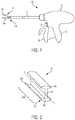
- FIG. 2is a perspective view illustration of a compression member of the powered surgical device of FIG. 1 ;
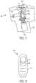
- FIG. 3is a side view illustration of the powered surgical device of FIG. 1 ;
- FIG. 4is a side cutaway view of another embodiment of a powered surgical device
- FIG. 5is a perspective, partially cutaway view of another embodiment of a powered surgical device
- FIG. 6is a side, cutaway, partially exploded view of another embodiment of a powered surgical device showing a bailout shaft;
- FIG. 7is a side cutaway view of the powered surgical device of FIG. 6 ;
- FIG. 8is a top view of the powered surgical device of FIG. 6 ;
- FIG. 9is a side cutaway view of another embodiment of a powered surgical device.
- FIG. 10is a perspective view of part of a bailout mechanism of the powered surgical device of FIG. 9 ;
- FIG. 11is a side cutaway view of another embodiment of a powered surgical device
- FIG. 12is another side cutaway view of the powered surgical device of FIG. 11 ;
- FIG. 13is a side cutaway view of another embodiment of a powered surgical device
- FIG. 14is a side cutaway view of another embodiment of a powered surgical device
- FIG. 15is a side cutaway view of another embodiment of a powered surgical device
- FIG. 16is a side cutaway view of another embodiment of a powered surgical device
- FIG. 17is another side cutaway view of the powered surgical device of FIG. 16 ;
- FIG. 18is a side cutaway view of another embodiment of a powered surgical device.
- FIG. 19is a side cutaway view of a bailout mechanism in a powered surgical device
- FIG. 20is another side cutaway view of the bailout mechanism of FIG. 19 ;
- FIG. 21is a cross sectional view of a rotation knob in a powered surgical device
- FIG. 22is an end view of the rotation knob of FIG. 21 ;
- FIG. 23is a side cutaway view of another embodiment of a powered surgical device.
- like-named components of the embodimentsgenerally have similar features, and thus within a particular embodiment each feature of each like-named component is not necessarily fully elaborated upon.
- linear or circular dimensionsare used in the description of the disclosed systems, devices, and methods, such dimensions are not intended to limit the types of shapes that can be used in conjunction with such systems, devices, and methods.
- a person skilled in the artwill recognize that an equivalent to such linear and circular dimensions can easily be determined for any geometric shape. Sizes and shapes of the systems and devices, and the components thereof, can depend at least on the anatomy of the subject in which the systems and devices will be used, the size and shape of components with which the systems and devices will be used, and the methods and procedures in which the systems and devices will be used.
- Various exemplary methods and devicesare provided for retracting a cutting assembly in the event of a failure on a motorized electrosurgical device.
- methods and devicesare provided for driving a drive shaft and/or a bevel gear manually on a motorized electrosurgical device.
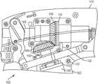
- FIG. 1illustrates one embodiment of a surgical device configured to grasp and cut tissue.
- the illustrated surgical device 100generally includes a proximal handle portion 10 , a shaft portion 12 , and an end effector 14 for grasping tissue.
- the proximal handle portion 10can be any type of pistol-grip, scissor grip, pencil-grip, or other type of handle known in the art that is configured to carry various actuators, such as actuator levers, knobs, triggers, or sliders, for actuating various functions such as rotating, articulating, approximating, and/or firing the end effector 14 .
- the proximal handle portion 10includes a stationary grip 22 and a closure grip 20 that is movable toward and away from the stationary grip 22 to open and close jaws of the end effector 14 .
- the shaft portion 12extends distally from the proximal handle portion and has a lumen (not shown) extending therethrough for carrying mechanisms for actuating the end effector 14 .
- the end effectorcan have a variety of sizes, shapes, and configurations. As shown in FIG. 1 , the end effector 14 includes a first upper jaw 16 a and a second lower jaw 16 b disposed at a distal end 12 d of the shaft portion 12 .
- the jaws 16 a , 16 bare moveable between an open position in which the jaws 16 a , 16 b are spaced a distance apart, and a closed position in which the jaws 16 a , 16 b are moved toward one another and are substantially opposed.
- a longitudinal axis of the upper jaw 16 acan be substantially parallel to a longitudinal axis of the lower jaw 16 b and the jaws 16 a , 16 b can be in direct contact for engaging tissue therebetween.
- the upper jaw 16 apivots relative to the shaft portion 12 and relative to the lower jaw 16 b while the lower jaw 16 b remains stationary.
- the illustrated jaws 16 a , 16 bhave a substantially elongate and straight shape, a person skilled in the art will appreciate that one or both of the jaws 16 a , 16 b can be in various directions.
- the jaws 16 a , 16 bcan have any suitable axial length for engaging tissue, and the length can be selected based on the targeted anatomical structure for transection and/or sealing.
- the surgical device 100can have a closure actuator that can be configured to open and close the jaws 16 a , 16 b of the end effector 14 .
- Manipulation of the closure actuatorcan pivot or otherwise move the jaws relative to one another such that the jaws can engage tissue, move anatomical structures, or perform other surgical functions.
- the closure actuatorcan have various sizes, shapes, and configurations, but in the illustrated embodiment the closure actuator includes the closure grip 20 and the stationary grip 22 .
- the closure grip 20can be moveable toward and away from stationary grip 22 , such as via pivoting.
- the closure grip 20can have a first position in which it is angularly offset and spaced apart from the stationary grip 22 and the jaws 16 a , 16 b of the end effector 14 are open.
- the closure grip 20can have a second position where it is positioned adjacent to, or substantially in contact with, the stationary grip 22 and the jaws 16 a , 16 b of the end effector 14 can engage tissue and apply a force to tissue disposed therebetween.
- the closure grip 20can be biased to the first open position with the jaws 16 a , 16 b of the end effector 14 being open, as shown in FIG. 1 .
- the closure grip 20can move the jaws 16 a , 16 b between the open and closed positions using manual or powered components.
- the closure grip 20can be coupled to gears that interact with a rack disposed within the handle.
- Manual movement of the closure grip 20 toward the stationary grip 22can move the rack either proximally or distally relative to the end effector 14 to either pull or push the jaws 16 a , 16 b closed.
- the drive shaftcan include or be coupled to a drive screw that can be moved proximally by a drive nut that is rotated by a series of gears.
- a motorcan be disposed in the proximal handle portion 10 and manual movement of the closure grip 20 can cause a control signal to be sent to the motor, which can interact with various gears or other components to cause the jaws 16 a , 16 b to close.
- the closure grip 20can interact with one or more locking features (not shown) configured to lock the closure grip 20 relative to the stationary handle 22 .
- the locking featurecan automatically engage when the closure grip 20 substantially contacts the stationary handle 22 or the locking feature can automatically engage at each position the closure grip 20 is pivoted through, such as via ratcheting.
- the surgical devicecan also have a second actuator, such as actuator 24 , that can be separate from the closure actuator 20 .
- the second actuatorcan be configured to advance a cutting assembly, apply energy to tissue, or both, and is referred to herein as a “firing actuator.”
- the firing actuator 24can have various sizes, shapes, and configurations, but in the illustrated embodiment it is in the form of a button or trigger that can be depressed by a user. In another embodiment, the firing actuator 24 can be in the form of a switch, lever, etc., that can be slid, pivoted, or otherwise moved by a user.
- Depressing or pivoting the actuatorcan activate various elements in the device, and can cause a cutting assembly to advance through the end effector and/or cause energy to be delivered to the jaws.
- depressing or pivoting the firing actuatorcan cause a cutting assembly to advance distally and/or retract proximally relative to the jaws 16 a , 16 b .
- the firing actuatorcan be in electrical communication with a motor disposed in the proximal handle portion 10 .
- the motorcan be operatively coupled to the cutting assembly using known components, such as one or more gears and a rack or drive screw.
- the cutting assemblycan be configured to transect tissue captured between the jaws, and it can be sized and shaped to transect or cut various thicknesses and types of tissue.
- the cutting assemblycan include an I-beam compression member 28 that travels through slots formed in each jaw to pull the jaws into a parallel orientation and to compress tissue therebetween.
- the compression member 28can include a cutting element (not shown) positioned at the distal end 28 d thereof and formed on a connecting portion 30 c of the compression member 28 .
- the cutting elementcan be integrally formed with the distal end 28 d of the compression member 28 .
- the cutting elementcan have a sharp or serrated edge configured to transect the tissue.
- the cutting elementcan be recessed relative to distal ends of upper and lower flanges 30 a , 30 b of the I-beam compression member 28 so that compression occurs prior to transecting or cutting of the tissue.
- the cutting elementcan include a shaft having a knife blade that is not attached to a compression member such that the cutting assembly can advance and retract relative to the jaws without applying compression to the tissue.
- the handle portion 10 of the surgical device 100can include components for operating the device, such as a motor 48 , a power source 50 , a generator 52 , and a processor 54 , as well as various sensors (not shown).
- the device 100can also include various components for delivering energy, such as radiofrequency or ultrasound energy, to tissue, and these components can be disposed at various locations in the device 100 , such as in the proximal handle portion 10 and/or in the jaws 16 a , 16 b .
- the firing actuator 24can be coupled to the processor 54
- the processor 54can be coupled to the motor 58 , the power source 50 , and/or the generator 52 (as well as any sensors provided).
- Firing the actuator 24sends a signal to the processor 54 , which can cause the power source 50 to provide power to the motor 48 through the processor 54 .
- the motor 48can drive the cutting assembly, and the processor 54 can control a speed and a direction of the motor, which in turn alters a speed and a direction of the cutting assembly.
- the generator 52can be a separate unit that is electrically connected to the surgical device 100 to decrease the size and weight of the surgical device 100 , and it can be operatively coupled to an actuator on the surgical device so that the device is configured to apply energy to tissue engaged by the end effector when the actuator is activated.
- the generatorcan be operably coupled to the firing actuator 24 or the generator can be coupled to a second actuator.
- the generatorcan be any suitable generator known in the art, such as an RF generator or an ultrasound generator.
- a lumen (not shown) of the shaft portion 12can carry electrical leads or wires that can deliver electrical energy to components of the end effector 14 .
- the generator 52can be coupled to the power source 50 , such as a battery disposed in the proximal handle portion 10 or it can be coupled to an external power source, such as an electrical outlet or have its own power source.
- FIG. 4illustrates one exemplary configuration of a surgical device 200 having components for operating the device.
- the surgical device 200can generally be configured and used similar to the surgical device 100 of FIGS. 1-3 .
- the surgical device 200has a shaft portion 212 , and a proximal handle portion 210 including a closure grip 220 and a stationary grip 222 .
- the surgical device 200has a firing actuator 224 that is configured to advance distally and/or retract proximally a cutting assembly through an end effector (not shown) positioned on a distal end of the shaft portion 212 .
- the firing actuator 224is a button that can be depressed by a user.
- the firing actuator 224is coupled to and in communication with a processor 260 , which can include a circuit board and/or a controller.
- the processor 260can be in communication with a motor 248 , a power source such as a battery, and/or a generator.
- the motor 248is disposed in the proximal handle portion 210 , and it can be operatively coupled to a gear box 252 , which is operably coupled to a motor bevel gear 254 .
- the motor bevel gear 254is operably coupled in turn to a drive bevel gear 256 , which is operably coupled to a drive shaft 258 . Activation of the firing actuator 224 can thus provide a signal to the processor 260 .
- the processor 260can cause power to be delivered from the power source to the motor 248 , which rotates the gear box 252 .
- the gear box 252causes the motor bevel gear 254 to rotate, which engages with and rotates the drive bevel gear 256 , which drives the drive shaft 258 distally or proximally.
- the drive shaft 258can be driven distally or proximally through known means, such as a thread along the drive shaft 258 .
- Distal movement of the drive shaft 258advances the cutting assembly distally through an end effector.
- Proximal movement of the drive shaft 258retracts the cutting assembly proximally from the end effector.
- the drive shaftcan be advanced and retracted using a number of different techniques, such as a rack system, one or more linkages, a ball bearing and nut system, a bevel and spur gear system, etc.
- the surgical device 200has a generator (not shown) that is operatively coupled to an actuator on the surgical device 200 so that the device 200 is configured to apply energy to tissue engaged by the end effector when the actuator is activated.
- the generatorcan be operably coupled to the firing actuator 224 or the generator can be coupled to a second actuator.
- the generatorcan be any suitable generator known in the art, such as an RF generator or an ultrasound generator.
- a lumen (not shown) of the shaft portion 212can carry electrical leads or wires that can deliver electrical energy to components of the end effector.
- a surgical deviceUnder normal operation of a surgical device as described above, power can be supplied from a power source, e.g., the battery, through a processor to a motor, resulting in distal or proximal movement of a cutting assembly through an end effector positioned on a distal end of the surgical device.
- the processorinstructs the power source to provide power to the motor.
- the surgical devicemay fail to successfully complete a cutting stroke, for example if the device jams during cutting because of thick tissue or if a power failure occurs. Removing the surgical device from a patient before retracting the cutting assembly may cause significant harm to the patient, though.
- a bailout mechanismis provided that can allow retraction of the cutting assembly in the event of a malfunction.
- a surgical devicecan be provided with a handle and an elongate shaft extending distally therefrom.
- the elongate shaftcan have an end effector at a distal end thereof, which can have first and second jaws.
- the jawscan be configured to engage tissue therebetween.
- a cutting assemblycan be configured to move relative to the first and second jaws so as to cut tissue engaged between the first and second jaws.
- a drive shaftcan extend from the handle through the elongate shaft.
- the drive shaftcan couple to the cutting assembly and can be configured to move the cutting assembly relative to the first and second jaws.
- the drive shaftcan be moved by a motorized gear assembly with at least one motor driven gear.
- a bailout gear assemblycan be positioned on the handle.
- the bailout gear assemblycan be configured to engage with the drive shaft and/or the gear assembly.
- the bailout gear assemblycan be configured to manually move the drive shaft and/or the motorized gear assembly during a bailout operation.
- the surgical devicecan be configured to advance and/or retract the cutting assembly from the jaws of the end effector by actuation of a motor.
- the surgical devicecan also have a bailout operation in which the bailout gear assembly engages the drive shaft and/or the motor gear assembly.
- the motor and/or motorized gear assemblycan be disengaged in some embodiments during the bailout operation.
- a surgeoncan manually manipulate the bailout gear assembly to drive the drive shaft and/or rotate the motorized gear assembly, to thereby drive the drive shaft.
- Driving the drive shaft and/or rotating the motorized gear assemblycan cause the cutting assembly to move proximally relative to the first and second jaws, retracting the cutting assembly out of the first and second jaws.
- the first and second jawscan then open to release tissue engaged between, and a surgeon can subsequently withdraw the surgical device from a patient.
- the bailout operationmay allow a surgeon to rapidly remove the surgical device during any emergency situation, for example if normal operation of the device malfunctions, while minimizing any harm to the patient.
- Manual bailout of the cutting assembly in the form of directly driving the drive shaft and/or rotating the gear assembly to drive the drive shaftmay also be fast and less prone to continued device errors than other mechanisms, ensuring a safe retraction during a potentially high-stress situation in which the surgeon is attempting to monitor the patient and safely remove the device at the same time.
- FIG. 5illustrates a proximal portion of one embodiment of a surgical device 300 having a bailout mechanism.
- the surgical device 300can generally be configured and used similar to the surgical devices 100 , 200 of FIGS. 1-4 .
- Surgical device 300has a proximal handle portion 310 including a stationary grip 322 , only a portion of which is shown.
- the surgical device 300has a shaft portion, a closure grip, and a firing actuator (not shown) that can be configured to advance distally and/or retract proximally a cutting assembly through an end effector (not shown) positioned on a distal end of the shaft portion.
- the closure gripis effective to move jaws of the end effector between open and closed positions.
- the firing actuatoris connected to and in communication with a processor 360 within the proximal handle portion 310 .
- the processor 360is in communication with a motor (not shown) and a power source (not shown) such as a battery.
- the motoris operably coupled to a gear box and is disposed in the proximal handle portion 310 .
- the motor and the gear boxare operatively coupled to a motor bevel gear (not shown) that is operably coupled to a drive bevel gear (not shown), which either directly or via one or more additional gears or other components is effective to move a drive shaft 358 proximally or distally upon rotation of the drive bevel gear.
- a first bailout spur gear 330is coupled to the drive bevel gear and rotates with the drive bevel gear.
- a ring 336is positioned externally to the proximal handle portion 310 on a proximal end of the proximal handle portion 310 .
- the ring 336is coupled to a bailout shaft 338 .
- the bailout shaft 338extends longitudinally in the direction of the drive shaft 358 .
- On an opposite end of the bailout shaft 338 to the ring 336is a second bailout spur gear 332 .
- the bailout shaft 338extends through a stopper 340 and a spring 334 .
- the spring 334biases the second bailout spur gear 332 distally to maintain the second spur gear 332 out of alignment with the spur gear 330 coupled to the drive bevel gear.
- a switch 339is positioned in the proximal end of the proximal handle portion 310 and is coupled to the bailout shaft 338 . The switch is connected between the processor and the motor and is configured to open and terminate the connection between the processor and the motor when the bailout shaft 338 moves proximally.
- the first bailout spur gear 330When the device is under a normal operation, the first bailout spur gear 330 is rotated by the drive bevel gear, but the first bailout spur gear 330 will not engage with any other gears.
- the second bailout spur gear 332remains unmoved and out of engagement with the first bailout spur gear 330 .
- Actuation of the firing actuatorsends a signal to the processor 360 , which drives the motor by providing power to the motor from the power source.
- the motordrives the gear box, which drives the motor bevel gear, which drives the drive bevel gear.
- the drive bevel gearrotates, causing the drive shaft 358 to advance and retract the cutting assembly.
- the switch 339is closed, providing a connection between the processor and the motor so that the processor can power the motor.
- the ring 336can be pulled in a proximal direction, moving the ring 336 and the bailout shaft 338 proximally.
- the switch 339is opened, severing the connection between the processor 360 and the motor.
- the motorthus cannot be accidentally activated while the cutting assembly is being retracted during the bailout operation.
- the spring 334compresses as force is applied to overcome the spring bias, and the second bailout spur gear 332 is pulled proximally with the motion of the ring 336 and the bailout shaft 338 .
- the second bailout spur gear 332is brought into alignment with the first bailout spur gear 330 coupled to the drive bevel gear so that gear teeth on each bailout spur gear 330 , 332 mesh together.
- the ring 336is rotated, which rotates the second bailout spur gear 332 .
- Rotation of the second bailout spur gear 332causes rotation of the first bailout spur gear 330 .
- rotation of the first bailout spur gear 330causes rotation of the drive bevel gear.
- Rotation of the drive bevel geardrives the drive shaft 358 , and the cutting assembly is retracted from the jaws, allowing the jaws to open.
- the ring 336is held proximally by a user during rotation.
- the ringcan be held proximally by various mechanisms within the device 300 to make rotation of the ring easier.
- a groovecan be made circumferentially around the bailout shaft, and the bailout shaft can extend through a second ring that can be fixed to an interior surface of the proximal handle portion.
- the second ringcan snap into the grove on the bailout shaft and hold the bailout shaft in a proximal position. After a bailout operation, the ring can be forced distally to cause the second ring to disengage from the groove.
- the ring 336is configured to allow rotation in either direction to allow both advancement and retraction of the cutting assembly. Other variations can allow rotation of the ring in only one direction to allow only retraction of the cutting assembly. The cutting assembly can be retracted as long as the ring 336 is rotated. Other embodiments can include mechanisms to prevent over-retraction, such as a stopper positioned in the path of retraction in the proximal handle portion to contact the cutting assembly and prevent further retraction.
- the surgical device 300can be reused and normal operation can be resumed by releasing the ring 336 and allowing the spur gear 332 to move distally out of alignment with the spur gear 330 .
- the switch 339can be closed as the bailout shaft 338 returns to its original distal position.
- Other variationscan prevent the surgical device from being reused to prevent a malfunctioning surgical device from being used in other operations.
- a groovecan be made circumferentially around the bailout shaft, and the bailout shaft can extend through a second ring that can be fixed to an interior surface of the proximal handle portion.
- the second ringcan snap into the grove on the bailout shaft and hold the bailout shaft in a permanently-proximal position.
- the spur gearsthus could not be disengaged.
- the switchcan also be permanently held open when the switch is opened during a bailout operation. The permanently-opened switch would permanently break the connection between the motor and the processor.
- FIGS. 6-8illustrate another embodiment of a surgical device 400 having a bailout mechanism.
- the surgical device 400can generally be configured and used similar to the surgical devices 100 , 200 of FIGS. 1-4 .
- Surgical device 400has a proximal handle portion 410 including a stationary grip 422 .
- the surgical device 400has a shaft portion, a closure grip, and a firing actuator (not shown) that can be configured to advance distally and/or retract proximally a cutting assembly through an end effector (not shown) positioned on a distal end of the shaft portion.
- the closure gripis effective to move jaws of the end effector between open and closed positions.
- the firing actuatoris connected to and in communication with a processor (not shown) within the proximal handle portion 410 .
- the processoris in communication with a motor 448 and a power source (not shown) such as a battery.
- the motor 448is operably coupled to a gear box 452 and is disposed in the proximal handle portion 410 .
- the motor 448 and the gear box 452are operatively coupled to a motor bevel gear 454 that is operably coupled to a drive bevel gear 456 , which either directly or via one or more additional gears or other components is effective to move a drive shaft 458 proximally or distally upon rotation of the drive bevel gear 456 .
- the motor 448 and the gear box 452are coupled to the motor bevel gear 454 through a spring 430 .
- the spring 430biases the motor bevel gear 454 toward the drive bevel gear 456 to keep the motor bevel gear 454 engaged with the drive bevel gear 456 .
- a bailout shaft 436extends through a top surface of the proximal handle portion 410 , past the drive bevel gear 456 , and is positioned adjacent to but spaced apart from the motor bevel gear 454 . On either side of the bailout shaft 436 are bailout bevel gears 432 configured to engage the drive bevel gear 456 .
- the surgical device 400has two bailout bevel gears 432 , other variations can have one or more bevel gears positioned to engage the drive bevel gear.
- the bailout shaft 436has a bailout knob 434 positioned on the bailout shaft's external end that is external to the proximal handle portion 410 and that is configured to rotate the bailout bevel gears 432 .
- the surgical device 400has a knob, other embodiments can use a variety of mechanisms to cause rotation of the one or more bevel gears, for example a lever, a switch, a dial, etc.
- the bailout knob 434is configured to be pressed, causing the bailout shaft 436 to move toward the bevel gears 454 , 456 .
- the bailout shaft 436When the device is under a normal operation, the bailout shaft 436 , the bailout bevel gears 432 , and the bailout knob 434 do not affect operation of the surgical device 400 .
- the bailout shaft 436is positioned a distance away from the motor bevel gear 454 .
- the bailout bevel gears 432are also spaced apart from the drive bevel gear 456 and do not engage the drive bevel gear 456 .
- Actuation of the firing actuatorcauses the processor to drive the motor 448 by providing power to the motor from the power source.
- the motor 448drives the gear box 452 , which drives the motor bevel gear 454 , which is in engagement with the drive bevel gear 456 due to the spring 430 .
- the drive bevel gear 456rotates, causing the drive shaft 458 to advance and retract the cutting assembly.
- the bailout knob 434can be pressed, as seen in FIG. 7 .
- the bailout shaft 436moves toward the motor bevel gear 454 due to force applied to the bailout knob 434 , and the bailout bevel gears 432 engage with the drive bevel gear 456 .
- An end of the bailout shaft 436 opposite to the bailout knob 434contacts the motor bevel gear 454 as the bailout shaft 436 is activated.
- the motor bevel gear 454moves away from and out of engagement with the drive bevel gear 456 .
- the motor 448 and the gear box 452cannot drive the drive shaft 458 because the bevel gears 454 , 456 no longer engage one another, preventing accidental activation of the motor 448 .
- the bailout shaft 436is kept in its engaged position by a locking barb 438 that latches internally in the proximal handle portion 410 when the bailout shaft 436 is engaged.
- the bailout knob 434can be rotated to rotate the bailout bevel gears 432 , which engage with and rotate the drive bevel gear 456 .
- Rotation of the drive bevel gear 456causes retraction or advancement of the drive shaft 458 and this retraction or advancement of the cutting assembly.
- the bailout knob 434can be configured to allow rotation in either direction to allow both advancement and retraction of the cutting element. Other variations can allow rotation of the bailout knob in only one direction to allow only retraction of the cutting assembly. The cutting assembly can be retracted as long as the bailout knob 434 is rotated. Variations can include mechanisms to prevent over-retraction, such as a stopper positioned in the path of retraction in the proximal handle portion to contact the cutting assembly and prevent further retraction.
- the surgical device 400can include a removable cover 440 that must be removed to access the bailout knob 434 , and an engagement pathway 442 on a top surface of the device 400 that requires a select amount of pressure in a particular location to force the bailout shaft 436 into an engaged position, preventing accidental engagement of the bailout shaft 436 .
- a cover and an engagement pathwaydo not require a cover and an engagement pathway.
- the surgical device 400can be reused to return to the normal operation by releasing the locking barb 438 and allowing the spring 430 to force the motor bevel gear 454 to move the bailout shaft 436 away from the motor, causing the motor bevel gear 454 to reengage the drive bevel gear 456 and the bailout bevel gears 432 to disengage from the drive bevel gear 456 .
- the motor 448 and the gear box 452can then drive the drive shaft 458 .
- Other variationscan prevent the surgical device from being reused to prevent a malfunctioning surgical device from being used in other operations.
- the locking barb 438can be configured to not be releasable once the locking barb 438 latches internally in the proximal handle portion 410 when the bailout shaft 436 is engaged.
- FIGS. 9-10illustrate a proximal portion of another embodiment of a surgical device 500 having a bailout mechanism.
- the surgical device 500can generally be configured and used similar to the surgical devices 100 , 200 of FIGS. 1-4 .
- Surgical device 500has a proximal handle portion 510 including a stationary grip 522 .
- the surgical device 500has a shaft portion, a closure grip, and a firing actuator (not shown) that can be configured to advance distally and/or retract proximally a cutting assembly through an end effector (not shown) positioned on a distal end of the shaft portion.
- the closure gripis effective to move jaws of the end effector between open and closed positions.
- the firing actuatoris connected to and in communication with a processor (not shown) within the proximal handle portion 510 .
- the processoris in communication with a motor 548 and a power source (not shown) such as a battery.
- the motor 548is operably coupled to a gear box 552 and is disposed in the proximal handle portion 510 .
- the motor 548 and the gear box 552are operatively coupled to a motor bevel gear 554 that is operably coupled to a drive bevel gear 556 , which either directly or via one or more additional gears or other components is effective to move the drive shaft 458 proximally or distally upon rotation of the drive bevel gear 556 .
- a bailout bevel gear 530operably engages the motor bevel gear 554 .
- a beveled cylinder 532operably engages the bailout bevel gear 530 and extends from the bailout bevel gear 530 to an external surface of the proximal handle portion 510 .
- the beveled cylinderis configured to be rotatable and to rotate the bailout bevel gear 530 .
- a hook lever 535illustrated in FIG. 10 , has a handle 536 and a beveled cavity 534 that is configured to receive and engage the beveled cylinder 532 .
- the hook lever 535is stored under a removable cover 538 on the proximal handle portion 510 .
- the cover 538also covers the beveled cylinder 532 .
- Other variationsdo not have to have a cover or can cover the hook lever 535 under a first cover and the beveled cylinder under a second cover.
- the hook lever 535is configured to be slid onto the beveled cylinder 532 and to be rotatable, which rotates the beveled cylinder 532 .
- the bailout bevel gear 530 and the beveled cylinder 532rotate with rotation of the motor bevel gear 554 and do not affect operation of the surgical device 500 .
- Actuation of the firing actuatorsends a signal to the processor, which drives the motor 548 by providing power to the motor 548 from the power source.
- the motor 548drives the gear box 552 , which drives the motor bevel gear 554 , which drives the drive bevel gear 556 .
- the drive bevel gear 556rotates, causing the drive shaft 558 to advance and retract the cutting assembly.
- the hook lever 535can be pushed onto the beveled cylinder 532 and can be rotated. Rotating the hook lever 535 rotates the beveled cylinder 532 , which rotates the bailout bevel gear 530 . Because the bailout bevel gear 530 engages with the motor bevel gear 554 , the motor bevel gear 554 rotates and in turn rotates the drive bevel gear 556 and ultimately translates the drive shaft 558 . Thus rotation of the hook lever 535 causes retraction or advancement of the drive shaft 558 and retraction or advancement of the cutting assembly.
- the hook lever 535is configured to allow rotation in either direction to allow both advancement and retraction of the cutting assembly. Other variations can allow rotation of the hook lever in only one direction to allow only retraction of the cutting assembly. The cutting assembly can be retracted as long as the hook lever 535 is rotated. Other embodiments can include mechanisms to prevent over-retraction, such as a stopper positioned in the path of retraction in the proximal handle portion to contact the cutting assembly and prevent further retraction.
- the surgical device 500can be reused by removing the hook lever 535 , returning to the normal operation.
- the motor 548 and the gear box 552can then drive the drive shaft 558 .
- Other variationscan prevent the surgical device from being reused to prevent a malfunctioning surgical device from being used in other operations.
- the hook lever 535can be configured to not be releasable once the hook lever 535 is pushed onto the beveled cylinder 532 .
- FIGS. 11-12illustrate another embodiment of a surgical device 600 having a bailout mechanism.
- the surgical device 600can generally be configured and used similar to the surgical devices 100 , 200 of FIGS. 1-4 .
- Surgical device 600has a proximal handle portion 610 .
- the surgical device 600has a shaft portion, a closure grip, and a firing actuator (not shown) that can be configured to advance distally and/or retract proximally a cutting assembly through an end effector (not shown) positioned on a distal end of the shaft portion.
- the closure gripis effective to move jaws of the end effector between open and closed positions.
- the firing actuatoris connected to and in communication with a processor (not shown) within the proximal handle portion 610 .
- the processoris in communication with a motor 648 and a power source (not shown) such as a battery.
- the motor 648is operably coupled to a gear box 652 and is disposed in the proximal handle portion 610 .
- the motor 648 and the gear box 652are operatively coupled to a motor bevel gear 654 that is operably coupled to a drive bevel gear 656 , which either directly or via one or more additional gears or other components is effective to move a drive shaft 658 proximally or distally upon rotation of the drive bevel gear 656 .
- a bailout gear 632is distally and proximally slidably positioned on a bailout shaft 634 .
- the bailout gear 632extends vertically above the drive shaft 658 and the drive bevel gear 656 , and the bailout shaft 634 extends substantially parallel to the drive shaft 658 .
- a portion of the bailout gear 632passes externally through a slot 636 in a top surface of the proximal handle portion 610 so that the bailout gear 632 is accessible to a user.
- the bailout gear 632is configured to slide proximally along the bailout shaft 634 to move into and out of engagement with the drive bevel gear 656 .
- a spring 630is positioned proximally to the drive bevel gear 656 and biases the drive bevel gear 656 distally to keep the drive bevel gear 656 engaged with the motor bevel gear 654 .
- the bailout gear 632When the device is under a normal operation, the bailout gear 632 is positioned distal of the drive bevel gear 656 and does not engage the drive bevel gear 656 .
- Actuation of the firing actuatorsends a signal to the processor, which drives the motor 648 by providing power to the motor 648 from the power source.
- the motor 648drives the gear box 652 , which drives the motor bevel gear 654 , which drives the drive bevel gear 656 .
- the drive bevel gear 656rotates, causing the drive shaft 658 to advance and retract the cutting assembly.
- the bailout gear 632can be slid proximally along the bailout shaft 634 by manually sliding a portion of the bailout gear 632 that extends externally through the slot 636 .
- the bailout gear 632contacts and engages with the drive bevel gear 656 . Further proximal movement overcomes spring bias of the spring 630 , causing the drive bevel gear 656 to move proximally to disengage from the motor bevel gear 654 . Activation of the motor 648 will thus not cause rotation of the drive bevel gear 656 during the bailout operation.
- the bailout gear 632can be rotated manually. Rotating the bailout gear 632 rotates the drive bevel gear 656 , which causes translation of the drive shaft 658 . Thus rotation of the bailout gear 632 causes retraction or advancement of the drive shaft 658 and retraction or advancement of the cutting assembly.
- the bailout gear 632is held proximally by a user during rotation.
- the bailout gearcan be held proximally by various mechanisms within the device to make rotation of the bailout gear easier.
- a tabcan extend from the bailout shaft, and the bailout gear can slide over the tab as the bailout gear is moved proximally.
- the tabcan be positioned distally to the bailout gear and keep the bailout gear in a proximal position along the bailout shaft while the bailout gear is rotated. After a bailout operation, the tab can be compressed by a user to allow the bailout gear to slide distally along the bailout shaft.
- the bailout gear 632is configured to allow rotation in either direction to allow both advancement and retraction of the cutting assembly. Other variations can allow rotation of the bailout gear in only one direction to allow only retraction of the cutting assembly. The cutting assembly can be retracted as long as the bailout gear 632 is rotated. Other embodiments can include mechanisms to prevent over-retraction, such as a stopper positioned in the path of retraction in the proximal handle portion to contact the cutting assembly and prevent further retraction.
- the surgical device 600can be reused by moving the bailout gear 632 distally along the bailout shaft 634 to return to the normal operation.
- the spring 630will force the drive bevel gear 656 distally, causing the drive bevel gear 656 to reengage the motor bevel gear 654 .
- the motor 648 and the gear box 652can then drive the drive shaft 658 .
- Other variationscan prevent the surgical device from being reused to prevent a malfunctioning surgical device from being used in other operations.
- the bailout gear 632can be configured to lock in a proximal position on the bailout shaft once the bailout gear 632 is slid proximally to engage the drive bevel gear 656 .
- Other embodimentscan incorporate a cover over the bailout gear and the slot to prevent accidental activation when the bailout gear is not needed and/or a flexible cover that slides with the bailout gear along the slot to prevent any contamination of an interior of the surgical device.
- FIG. 13illustrates a proximal portion of another embodiment of a surgical device 700 having a bailout mechanism.
- the surgical device 700can generally be configured and used similar to the surgical devices 100 , 200 of FIGS. 1-4 .
- Surgical device 700has a proximal handle portion 710 including a stationary grip 722 .
- the surgical device 700has a shaft portion (not shown), a closure grip 720 , and a firing actuator 724 that can be configured to advance distally and/or retract proximally a cutting assembly through an end effector (not shown) positioned on a distal end of the shaft portion.
- the closure gripis effective to move jaws of the end effector between open and closed positions.
- the firing actuatoris connected to and in communication with a processor 760 within the proximal handle portion 710 .
- the processor 760is in communication with a motor 748 and a power source (not shown) such as a battery.
- the motor 748is operably coupled to a gear box 752 and is disposed in the proximal handle portion 710 .
- the motor 748 and the gear box 752are operatively coupled to a motor bevel gear 754 that is operably coupled to a drive bevel gear 756 , which either directly or via one or more additional gears or other components is effective to move a drive shaft 758 proximally or distally upon rotation of the drive bevel gear 756 .
- a wheel 730extends vertically above the drive bevel gear 756 and extends externally through the proximal handle portion 710 , similar to the prior embodiment. While a wheel is shown in this embodiment, any mechanism capable of rotating a shaft can be used, such as a lever, a dial, a ratchet, etc.
- the wheelis coupled to a bailout shaft 736 , which extends through a shaft support 738 that allows the wheel 730 and the bailout shaft 736 to rotate.
- a bailout gear 734is positioned on the end of the bailout shaft 736 opposite to the wheel 730 .
- the bailout gear 734is operably engaged with the drive bevel gear 756 .
- the wheel 730is covered by a cover 732 and is configured to rotate the bailout shaft 736 and the bailout gear 734 upon manual rotation of the wheel 730 . Because the bailout gear 734 engages the drive bevel gear 756 , rotation of the bailout gear 734 rotates the drive bevel gear 756 .
- a spring 742is positioned below the motor 748 and the gear box 752 in the stationary grip 722 .
- the spring 742biases the motor 748 and the gear box 752 into engagement with the motor bevel gear 754 .
- the spring 742is coupled to a door 744 positioned below the spring 742 .
- the door 744is pivotally coupled to one side of the stationary grip 722 .
- a grenade pin 740fixes the door 744 on an opposite side to the pivot side of stationary grip 722 , keeping the door 744 in place and the spring 742 applying an upward force on the motor 748 and the gear box 752 to keep the motor 748 and the gear box 752 engaged with the motor bevel gear 754 .
- the grenade pin 740rests on two support posts 746 in the stationary grip 722 .
- a stop 747is positioned below the door 744 in the stationary grip 722 and is positioned to interfere with pivoting by the door 744 to prevent the door 744 from over-pivoting.
- the bailout gear 734 , the bailout shaft 736 , and the wheel 730rotate freely with the drive bevel gear 756 .
- Actuation of the firing actuatorsends a signal to the processor 760 , which drives the motor 748 by providing power to the motor 748 from the power source.
- the motor 748drives the gear box 752 , which drives the motor bevel gear 754 , which drives the drive bevel gear 756 .
- the drive bevel gear 756rotates, causing the drive shaft 758 to advance and retract the cutting assembly.
- the grenade pin 740can be pulled free from the stationary grip 722 . Removal of the grenade pin 740 allows the door 744 to pivot away from the spring 742 , causing the spring 742 to no longer provide an upward force to keep the motor 748 and the gear box 752 engaged with the motor bevel gear 754 . The motor 748 and the gear box 752 disengage from the motor bevel gear 754 , preventing the motor 748 from accidentally activating and rotating the motor bevel gear 754 during the bailout operation and allowing for an easier manual rotation of the drive bevel gear 756 . The cover 732 can be removed, exposing the wheel 730 .
- Manual rotation of the wheel 730can translate into rotation of the bailout shaft 736 , the bailout gear 734 , and thus the drive bevel gear 756 .
- Rotation of the drive bevel gear 756can in turn ultimately drive the drive shaft 758 and retract the cutting assembly.
- the wheel 730is configured to allow rotation in either direction to allow both advancement and retraction of the cutting assembly. Other variations can allow rotation of the wheel in only one direction to allow only retraction of the cutting assembly.
- the cutting assemblycan be retracted as long as the wheel 730 is rotated.
- Other embodimentscan include mechanisms to prevent over-retraction, such as a stopper positioned in the path of retraction in the proximal handle portion to contact the cutting assembly and prevent further retraction.
- the surgical device 700can be reused and returned to the normal operation by releasing the wheel 730 and reinserting the grenade pin 740 .
- the stop 747can stop the door 744 from over-pivoting, allowing reinsertion of the grenade pin 740 to pivot the door 744 back into the door's original position.
- the door 744will thus recompress the spring 742 , causing upward force on the motor 748 and the gear box 752 , which will reengage the motor bevel gear 754 .
- Other variationscan prevent the surgical device from being reused to prevent a malfunctioning surgical device from being used in other operations.
- the door and the stopcan be removed such that pulling the grenade pin causes the motor and the gear box to permanently fall out of engagement with the motor bevel gear. In such an embodiment, the motor and the gear box could be completely removed from the surgical device.
- FIG. 14illustrates a proximal portion of another embodiment of a surgical device 800 having a bailout mechanism.
- the surgical device 800can generally be configured and used similar to the surgical devices 100 , 200 of FIGS. 1-4 .
- Surgical device 800has a proximal handle portion 810 including a stationary grip 822 .
- the surgical device 800has a shaft portion (not shown), a closure grip 820 , and a firing actuator 824 that can be configured to advance distally and/or retract proximally a cutting assembly through an end effector (not shown) positioned on a distal end of the shaft portion.
- the closure gripis effective to move jaws of the end effector between open and closed positions.
- the firing actuatoris connected to and in communication with a processor 860 within the proximal handle portion 810 .
- the processor 860is in communication with a motor 848 and a power source (not shown) such as a battery.
- the motor 848is operably coupled to a gear box 852 and is disposed in the proximal handle portion 810 .
- the motor 848 and the gear box 852are operatively coupled to a motor bevel gear 854 that is operably coupled to a drive bevel gear 856 , which either directly or via one or more additional gears or other components is effective to move a drive shaft 858 proximally or distally upon rotation of the drive bevel gear 856 .
- a lever 830extends vertically above the drive bevel gear 856 and extends externally through the proximal handle portion 810 .
- the lever 830is operably engaged with the drive bevel gear 856 through teeth on the lever 830 .
- the lever 830is configured to rotate the drive bevel gear 856 upon rotation of the lever 830 .
- any mechanism capable of rotating the drive bevel gearcan be used, such as a wheel, dial, ratchet, etc.
- a trap door 834is positioned below the motor 848 and the gear box 852 in the stationary grip 822 .
- the trap doorkeeps the motor 848 and the gear box 852 engaged with the motor bevel gear 854 .
- the trap door 834is pivotally coupled on one side of the stationary grip 822 .
- a stop 832is positioned below the trap door 834 in the stationary grip 822 and is positioned to interfere with pivoting by the trap door 834 to prevent the trap door 834 from over-pivoting.
- the lever 830rotates freely with the drive bevel gear 856 .
- Actuation of the firing actuatorsends a signal to the processor 860 , which drives the motor 848 by providing power to the motor 848 from the power source.
- the motor 848drives the gear box 852 , which drives the motor bevel gear 854 , which drives the drive bevel gear 856 .
- the drive bevel gear 856rotates, causing the drive shaft 858 to advance and retract the cutting assembly.
- the trap door 834can be opened. Opening the trap door 834 causes the motor 848 and the gear box 852 to drop away from and disengage from the motor bevel gear 854 , preventing accidental activation of the motor 848 during the bailout operation and allowing easier rotation of the drive bevel gear 856 . Manual manipulation of the lever 830 can cause rotation of the drive bevel gear 856 and driving of the drive shaft 858 , retracting the cutting assembly.
- the lever 830is configured to allow rotation of the drive bevel gear 856 in only one direction to allow only retraction of the cutting assembly.
- Other variationscan allow manipulation of the lever in both directions to allow advancement or retraction of the cutting assembly.
- the cutting assemblycan be retracted as long as the lever 830 is manipulated.
- Other embodimentscan include mechanisms to prevent over-retraction, such as a stopper positioned in the path of retraction in the proximal handle portion to contact the cutting assembly and prevent further retraction.
- the surgical device 800can be reused and returned to normal operation by releasing the lever 830 and closing the trap door 834 .
- the stop 832can prevent the trap door 834 from over-pivoting, allowing closure of the trap door 834 and upward force on the motor 848 and the gear box 852 to cause re-engagement of the motor bevel gear 854 .
- a second stopcan be added below the motor and the gear box and above the trap door to prevent the motor and the gear box from moving too far away from the motor bevel gear.
- a tabcan be added to a proximal end of the motor to engage the second stop.
- Other variationscan prevent the surgical device from being reused to prevent a malfunctioning surgical device from being used in another operation.
- the stopcan be removed such that opening the trap door causes the motor and the gear box to permanently fall out of engagement with the motor bevel gear.
- the motor and gear boxcan be completely removed from the surgical device in some embodiments.
- the connection between the motor and the processorcan be accomplished through quick connect wires.
- a usercan quickly and easily disconnect the motor from the processor, which may allow for easier removal of the motor and the gear box from the surgical device and/or prevent activation of the motor and gear box during the bailout operation.
- FIG. 15illustrates a portion of another embodiment of a surgical device 900 having a bailout mechanism.
- the surgical device 900can generally be configured and used similar to the surgical devices 100 , 200 of FIGS. 1-4 .
- Surgical device 900has a proximal handle portion 910 including a stationary grip 922 .
- the surgical device 900has a shaft portion (not shown), a closure grip 920 , and a firing actuator 924 that can be configured to advance distally and/or retract proximally a cutting assembly through an end effector (not shown) positioned on a distal end of the shaft portion.
- the closure gripis effective to move jaws of the end effector between open and closed positions.
- the firing actuatoris connected to and in communication with a processor (not shown) within the proximal handle portion 910 .
- the processoris in communication with a motor 948 and a power source (not shown) such as a battery.
- the motor 948is operably coupled to a gear box 952 and is disposed in the proximal handle portion 910 .
- the motor 948 and the gear box 952are operatively coupled to a motor bevel gear 954 that is operably coupled to a drive bevel gear 956 , which either directly or via one or more additional gears or other components is effective to move a drive shaft 958 proximally or distally upon rotation of the drive bevel gear 956 .
- a wheel 930extends vertically above the drive bevel gear 956 and extends externally through the proximal handle portion 910 .
- the wheel 930is operably engaged with the drive bevel gear 956 and is covered by a cover 932 .
- the wheel 930is configured to rotate the drive bevel gear 956 upon manual rotation of the wheel 930 .
- any mechanism capable of rotating the drive bevel gearcan be used, such as a lever, dial, ratchet, etc.
- a ratchet switch 934is coupled to the motor bevel gear 954 and extends to an external side surface of the proximal handle portion 910 .
- a spring 936is coupled between the gear box 952 and the motor bevel gear 954 .
- the spring 936biases the motor bevel gear 954 toward the drive bevel gear 956 to keep the motor bevel gear 954 engaged with the drive bevel gear 956 .
- the ratchet switch 934is configured to move between two positions. In a first position of the ratchet switch 934 , the motor bevel gear 954 is engaged with the drive bevel gear 956 and the spring 936 is in a non-compressed state.
- the ratchet switch 934is configured to be moved to a second position by a user, in which the ratchet switch 934 is adjacent the stationary grip 922 and away from the drive bevel gear 956 .
- the ratchet switch 934is coupled to the motor bevel gear 954 , movement away from the drive bevel gear 956 causes the motor bevel gear 954 to also move away from the drive bevel gear 956 . Movement of the motor bevel gear 954 causes the spring 936 to compress. Once enough force is applied to overcome the spring bias, the spring 936 compresses and the motor bevel gear 954 moves out of engagement with the drive bevel gear 956 . On an external side surface of the proximal handle portion 910 , the ratchet switch 934 locks into the second position, which keeps the spring 936 compressed and the motor bevel gear 954 out of engagement with the drive bevel gear 956 . The ratchet switch 934 is configured to be pushed in to unlock the ratchet switch 934 at each of its two positions.
- the wheel 930rotates freely with the drive bevel gear 956 .
- Actuation of the firing actuatorsends a signal to the processor, which drives the motor 948 by providing power to the motor 948 from the power source.
- the motor 948 and the gear box 952drive the motor bevel gear 954 , which drives the drive bevel gear 956 .
- the drive bevel gear 956rotates, causing the drive shaft 958 to advance and retract the cutting assembly.
- the ratchet switch 934can be moved from its first position to its second position by a user. Moving the ratchet switch 934 to the second position away from the drive bevel gear 956 causes the motor bevel gear 954 to disengage from the drive bevel gear 956 as the spring 936 is compressed, preventing the motor 948 from accidentally activating and rotating the drive bevel gear 956 and allowing for an easier rotation of the drive bevel gear 956 .
- the cover 932can be opened by a user, and the wheel 930 can be rotated, causing rotation of the drive bevel gear 956 and driving of the drive shaft 958 . As the drive shaft 958 is driven, the cutting assembly retracts.
- the wheel 930is configured to allow rotation of the drive bevel gear 956 in both directions to allow for both advancement and retraction of the cutting assembly.
- Other variationscan allow manipulation of the wheel in only one direction to allow only retraction of the cutting assembly.
- the cutting assemblycan be retracted as long as the wheel 930 is manipulated.
- Other embodimentscan include mechanisms to prevent over-retraction, such as a stopper positioned in the path of retraction in the proximal handle portion to contact the cutting element and prevent further retraction.
- the surgical device 900can be reused and returned to normal operation by releasing the wheel 930 and returning the ratchet switch 934 to its first position.
- the spring 936can then apply an upward force on the motor bevel gear 954 to cause re-engagement between the motor bevel gear 954 and the drive bevel gear 956 .
- Other variationscan prevent the surgical device from being reused to prevent a malfunctioning surgical device from being used in other operations.
- the ratchet switchcan be configured to only work in one direction to prevent the switch from being returned to its first position such that the motor bevel gear cannot be reengaged with the drive bevel gear.
- FIGS. 16-17illustrate a portion of another embodiment of a surgical device 1000 having a bailout mechanism.
- the surgical device 1000can generally be configured and used similar to the surgical devices 100 , 200 of FIGS. 1-4 .
- Surgical device 1000has a proximal handle portion 1010 including a stationary grip 1022 .
- the surgical device 1000has a shaft portion, a closure grip, and a firing actuator (not shown) that can be configured to advance distally and/or retract proximally a cutting assembly through an end effector (not shown) positioned on a distal end of the shaft portion.
- the closure gripis effective to move jaws of the end effector between open and closed positions.
- the firing actuatoris connected to and in communication with a processor (not shown) within the proximal handle portion 1010 .
- the processoris in communication with a motor 1048 and a power source (not shown) such as a battery.
- the motor 1048is operably coupled to a gear box 1052 and is disposed in the proximal handle portion 1010 .
- the motor 1048 and the gear box 1052are operatively coupled to a motor bevel gear 1054 that is operably coupled to a drive bevel gear 1056 , which either directly or via one or more additional gears or other components is effective to move a drive shaft 958 proximally or distally upon rotation of the drive bevel gear 956 .
- a wheel 1030is positioned proximally to the drive bevel gear 1056 and is covered by a removable access door 1032 .
- the wheel 1030has a beveled opening in the wheel's center that is configured to be engageable with a beveled cylinder 1036 coupled to a proximal end of the drive bevel gear 1056 .
- the drive bevel gear 1056is also coupled to a spring mechanism 1034 that is positioned vertically above the drive bevel gear 1056 such that the drive bevel gear 1056 extends into a slot 1035 on the spring mechanism 1034 but is freely rotatable relative to the spring mechanism 1034 .
- the spring mechanism 1034contacts the access door 1032 and is in a compressed state when the access door 1034 is closed.
- the spring mechanism 1034is configured to expand proximally upon removal of the access door 1032 .
- the drive bevel gear 1056is configured to move proximally with movement of the spring mechanism 1034 , disengaging the drive bevel gear 1056 from the motor bevel gear 1054 .
- the beveled cylinder 1036 on the drive bevel gear 1056is thus configured to engage the wheel 1030 upon proximal movement of the drive bevel gear 1056 caused by expansion of the spring mechanism 1034 and removal of the access door 1032 .
- the wheel 1030is configured to be manually rotatable and rotate the drive bevel gear 1056 and the drive shaft 1058 .
- the wheel 1030When the device is under a normal operation, the wheel 1030 does not engage the beveled cylinder 1036 of the drive bevel gear 1056 .
- Actuation of the firing actuatorsends a signal to the processor, which drives the motor 1048 by providing power to the motor 1048 from the power source.
- the motor 1048drives the gear box 1052 , which drives the motor bevel gear 1054 , which drives the drive bevel gear 1056 .
- the drive bevel gear 1056rotates, causing the drive shaft 1058 to advance and retract the cutting assembly.
- the access door 1032can be removed. Removing the access door 1032 allows the spring mechanism 1034 to expand proximally, moving the drive bevel gear 1056 out of engagement with the motor bevel gear 1054 , preventing the motor 1048 from accidentally driving the drive shaft 1058 during the bailout operation.
- the beveled cylinder 1036 on the drive bevel gear 1056moves into engagement with the wheel 1030 .
- the wheel 1030can then be rotated to rotate the drive bevel gear 1056 and the drive shaft 1058 . As the drive shaft 1058 rotates, the cutting assembly is retracted.
- the wheel 1030is configured to allow rotation of the drive bevel gear 1056 in either direction to allow for both advancement and retraction of the cutting assembly.
- Other variationscan allow manipulation of the wheel in only one direction to allow only retraction of the cutting assembly.
- the cutting elementcan be retracted as long as the wheel 1030 is manipulated.
- Other embodimentscan include mechanisms to prevent over-retraction, such as a stopper positioned in the path of retraction in the proximal handle portion to contact the cutting assembly and prevent further retraction.
- the surgical device 1000can be reused and returned to normal operation by releasing the wheel 1030 and replacing the access door 1032 , forcing the spring mechanism 1034 to recompress distally and causing the drive bevel gear 1056 to move distally and reengage the motor bevel gear 1054 .
- Other variationscan prevent the surgical device from being reused to prevent a malfunctioning surgical device from being used in other operations.
- the spring mechanismcan require such a high force to recompress the spring mechanism that a user will be unable to recompress the spring mechanism and reengage the bevel gears.
- FIG. 18illustrates another embodiment of a surgical device 1100 having a bailout mechanism.
- the surgical device 1100can generally be configured and used similar to the surgical devices 100 , 200 of FIGS. 1-4 .
- Surgical device 1100has a proximal handle portion 1110 .
- the surgical device 1100has a shaft portion and a firing actuator (not shown) that can be configured to advance distally and/or retract proximally a cutting assembly through an end effector (not shown) positioned on a distal end of the shaft portion.
- the closure gripis effective to move jaws of the end effector between open and closed positions.
- the firing actuatoris connected to and in communication with a processor (not shown) within the proximal handle portion 1110 .
- the processoris in communication with a motor 1148 and a power source (not shown) such as a battery.
- the motor 1148is operably coupled to a gear box 1152 and is disposed in the proximal handle portion 1110 .
- the motor 1148 and the gear box 1152are operatively coupled to a motor bevel gear 1154 that is operably coupled to a drive bevel gear 1156 , which either directly or via one or more additional gears or other components is effective to move a drive shaft 1158 proximally or distally upon rotation of the drive bevel gear 1156 .
- a first spring 1134is positioned proximally to the drive bevel gear 1156 and biases the drive bevel gear 1156 distally to engage the motor bevel gear 1154 . While a wave spring is shown in the embodiment, any spring can be used.
- a second spring 1132is positioned distally from the drive bevel gear 1156 and biases a bailout shaft 1136 distally away from the drive bevel gear 1156 . Teeth 1138 are formed on a proximal end of the bailout shaft 1136 .
- Reciprocal teeth 1140are formed on a distal end of a bevel shaft 1142 that is coupled to the drive bevel gear 1156 on an opposite end of the bevel shaft 1142 to the teeth 1140 .
- a rotation knob 1130externally from the proximal handle portion 1110 .
- the drive shaft 1158runs longitudinally within the bailout shaft 1136 and the bevel shaft 1142 .
- the rotation knob 1130 and the bailout shaft 1136are configured to rotate and to move proximally so that the teeth 1138 can engage the teeth 1140 on the bevel shaft 1142 .
- the bevel shaft 1142 and the drive bevel gear 1156are configured to rotate and to move proximally to disengage the drive bevel gear 1156 from the motor bevel gear 1154 .
- the rotation knob 1130 and the bailout shaft 1136do not affect operation of the device 1100 and do not engage the bevel shaft 1142 and the drive bevel gear 1156 because of the spring 1132 .
- the drive bevel gear 1156engages the motor bevel gear 1154 and rotates, causing the bevel shaft 1142 to rotate freely with the drive bevel gear 1156 .
- Actuation of the firing actuatorsends a signal to the processor, which drives the motor 1148 by providing power to the motor 1148 from the power source.
- the motor 1148drives the gear box 1152 , which drives the motor bevel gear 1154 , which drives the drive bevel gear 1156 .
- the drive bevel gear 1156rotates, causing the drive shaft 1158 to advance and retract the cutting assembly.
- the rotation knob 1130can be moved proximally. Once the spring bias from the spring 1132 is overcome, the rotation knob 1130 can cause the bailout shaft 1136 to move proximally and the teeth 1138 to engage the teeth 1140 on the bevel shaft 1142 . Continued application of force proximally on the rotation knob 1130 can cause the bevel shaft 1142 and the drive bevel gear 1156 to overcome the spring bias from spring 1134 and move proximally as well, disengaging the drive bevel gear 1156 from the motor bevel gear 1154 and preventing the motor 1148 from accidentally driving the drive shaft 1158 during the bailout operation.
- the rotation knob 1130can be rotated to rotate the drive bevel gear 1156 and the drive shaft 1158 .
- the cutting assemblyis retracted.
- the rotation knob 1130is configured to allow rotation of the drive bevel gear 1156 in either direction to allow for both advancement and retraction of the cutting assembly.
- Other variationscan allow rotation of the rotation knob in only one direction to allow only retraction of the cutting assembly.
- the cutting assemblycan be retracted as long as the rotation knob 1130 is rotated.
- Other embodimentscan include mechanisms to prevent over-retraction, such as a stopper positioned in the path of retraction in the proximal handle portion to contact the cutting assembly and prevent further retraction.
- the surgical device 1100can be reused and returned to normal operation by releasing the rotation knob 1130 , which causes the springs 1132 , 1134 to move the rotation knob 1130 , the bailout shaft 1136 , the bevel shaft 1142 , and the drive bevel gear 1156 distally.
- the bailout shaft 1136 and the bevel shaft 1142will disengage while the bevel gears 1154 , 1156 will reengage.
- Other variationscan prevent the surgical device from being reused to prevent a malfunctioning surgical device from being used in other operations.
- the teeth on the bailout shaft and the bevel shaftcan permanently engage, preventing the rotation knob and the bailout shaft from disengaging the bevel shaft and the drive bevel gear.
- a lever 1230can be positioned above a bailout shaft 1236 .
- the lever 1230can extend externally from the proximal handle portion 1210 .
- the lever 1230can be biased by a spring 1232 , such as a torsion spring, and can engage the bailout shaft 1236 by extending between two stoppers 1234 that extend around the bailout shaft 1236 .
- the spring 1232can bias the bailout shaft 1236 distally away from a bevel shaft 1242 and a drive bevel gear 1256 . Similar to FIG.
- the bailout shaft 1236engages the bevel shaft 1242 by proximal movement in which teeth engage one another. Proximal movement is caused by lifting the lever 1230 , which rotates about a pivot point 1236 . Engagement between the lever 1230 and the bailout shaft 1236 forces the bailout shaft 1236 to move proximally to engage the bevel shaft 1242 coupled to the drive bevel gear 1256 . The bevel shaft 1242 and the drive bevel gear 1256 are both forced to move proximally by the movement of the bailout shaft 1236 . The drive bevel gear 1256 disengages a motor bevel gear 1254 as the drive bevel gear 1256 moves proximally, as seen in FIG. 20 and similar to FIG. 18 . A rotation knob as seen in FIG. 18 would then be used to translate the drive shaft 1236 and retract a cutting assembly.
- a rotation knob 1330can engage a drive shaft 1358 directly rather than engaging a bailout shaft with a bevel shaft, as seen in FIGS. 21-22 .
- the rotation knob 1330has spring plungers 1332 that pass through the rotation knob 1330 and are held radially away from the drive shaft 1358 by springs 1334 to allow free rotation of the drive shaft 1358 under normal operation.
- the spring plungers 1332Upon depressing the spring plungers 1332 to overcome the spring bias of the springs 1334 , the spring plungers 1332 extend radially inward and engage the drive shaft 1358 , coupling the rotation knob 1330 to the drive shaft 1358 .
- a drive bevel gearwould still need to be disengaged from a motor bevel gear through mechanisms as seen in FIGS. 18-20 .
- the rotation knob 1330can then be rotated to translate the drive shaft 1358 and retract a cutting assembly, similar to FIG. 18 .
- FIG. 23illustrates another embodiment of a surgical device 1400 having a bailout mechanism.
- the surgical device 1400can generally be configured and used similar to the surgical devices 100 , 200 of FIGS. 1-4 .
- Surgical device 1400has a proximal handle portion 1410 including a stationary grip 1422 .
- the surgical device 1400has a shaft portion, a closure grip, and a firing actuator (not shown) that can be configured to advance distally and/or retract proximally a cutting assembly through an end effector (not shown) positioned on a distal end of the shaft portion.
- the closure gripis effective to move jaws of the end effector between open and closed positions.
- the firing actuatoris connected to and in communication with a processor (not shown) within the proximal handle portion 1410 .
- the processoris in communication with a motor 1448 and a power source (not shown) such as a battery.
- the motor 1448is operably coupled to a gear box 1452 and is disposed in the proximal handle portion 1410 .
- the motor 1448 and the gear box 1452are operatively coupled to a motor bevel gear 1454 that is operably coupled to a drive bevel gear 1456 , which either directly or via one or more additional gears or other components is effective to move a drive shaft 1458 proximally or distally upon rotation of the drive bevel gear 1456 .
- a pin 1430is inserted into the stationary grip 1422 to couple the stationary grip 1422 to the proximal handle portion 1410 on one side of the stationary grip 1422 .
- a pivot point 1432allows the stationary grip 1422 to pivot in relation to the proximal handle portion 1410 .
- the pin 1430is configured to be removable, allowing the stationary grip 1422 to disconnect from the proximal handle portion 1410 on a side corresponding to the pin 1430 and to pivot about the pivot point 1432 . Pivoting of the stationary handle 1422 is configured to cause the motor bevel gear 1454 to disengage from the drive bevel gear 1456 as the motor bevel gear 1454 pivots with the stationary grip 1422 .
- a pawl 1436is coupled to the stationary grip 1422 on a side corresponding to the pivot point 1432 .
- the pawl 1436is configured to engage ratchet features 1434 radially distributed on a proximal side of the drive bevel gear 1456 upon pivot of the stationary grip 1422 .
- the pawl 1436is configured to cause rotation of the drive bevel gear 1456 due to repeated interaction between the pawl 1436 and the ratchet features 1434 as the stationary grip 1422 is pivoted back and forth on the pivot point 1432 .
- the pin 1430When the device is under a normal operation, the pin 1430 maintains a connection between the stationary grip 1422 and the proximal handle portion 1410 .
- the pawl 1436does not move, and the ratchet features rotate with the drive bevel gear 1456 .
- Actuation of the firing actuatorsends a signal to the processor, which drives the motor 1448 by providing power to the motor 1448 from the power source.
- the motor 1448drives the gear box 1452 , which drives the motor bevel gear 1454 , which drives the drive bevel gear 1456 .
- the drive bevel gear 1456rotates, causing the drive shaft 1458 to advance and retract the cutting assembly.
- the pin 1430can be pulled free from the stationary grip 1422 . Removal of the pin 1430 can cause the stationary grip 1422 to pivot away from the proximal handle portion 1410 around pivot point 1432 , causing the motor bevel gear 1454 and the drive bevel gear 1456 to disengage from one another, preventing the motor 1448 from accidentally activating and translating the drive shaft 1458 during the bailout operation.
- the pawl 1436engages the ratchet features 1434 and rotates the drive bevel gear 1456 upon repeated back and forth pivoting of the stationary grip 1422 . Rotation of the drive bevel gear 1456 can in turn drive the drive shaft 1458 and retraction of the cutting assembly.
- the pawl 1432is configured to allow rotation of the drive bevel gear 1456 in only one direction to allow only retraction of the cutting assembly. Other variations can allow rotation of the drive bevel gear in either direction to allow advancement and retraction of the cutting assembly.
- the cutting assemblycan be retracted as long as the pawl 1432 and the stationary grip 1422 are pivoted. Other embodiments can include mechanisms to prevent over-retraction, such as a stopper positioned in the path of retraction in the proximal handle portion to contact the cutting assembly and prevent further retraction.
- the surgical device 1400can be reused and returned to the normal operation by pivoting the stationary grip 1422 back into its starting position and replacing the pin 1430 , at which position the motor bevel gear 1454 will reengage the drive bevel gear 1456 .
- Other variationscan prevent the surgical device from being reused to prevent a malfunctioning surgical device from being used in other operations.
- the pincan be irreplaceable once removed, causing the motor bevel gear to permanently fall out of engagement with the drive bevel gear.
- the devices disclosed hereincan be designed to be disposed of after a single use, or they can be designed to be used multiple times. In either case, however, the device can be reconditioned for reuse after at least one use. Reconditioning can include any combination of the steps of disassembly of the device, followed by cleaning or replacement of particular pieces and subsequent reassembly. In particular, the device can be disassembled, and any number of the particular pieces or parts of the device can be selectively replaced or removed in any combination. Upon cleaning and/or replacement of particular parts, the device can be reassembled for subsequent use either at a reconditioning facility, or by a surgical team immediately prior to a surgical procedure.
- reconditioning of a devicecan utilize a variety of techniques for disassembly, cleaning/replacement, and reassembly. Use of such techniques, and the resulting reconditioned device, are all within the scope of the present application.
- components of the invention described hereinwill be processed before use.
- a new or used instrumentis obtained and if necessary cleaned.
- the instrumentcan then be sterilized.
- the instrumentis placed in a closed and sealed container, such as a plastic or TYVEK bag.
- the container and instrumentare then placed in a field of radiation that can penetrate the container, such as gamma radiation, x-rays, or high-energy electrons.
- the radiationkills bacteria on the instrument and in the container.
- the sterilized instrumentcan then be stored in the sterile container.
- the sealed containerkeeps the instrument sterile until it is opened in the medical facility.
- the deviceis sterilized. This can be done by any number of ways known to those skilled in the art including beta or gamma radiation, ethylene oxide, steam, and a liquid bath (e.g., cold soak).
- a liquid bathe.g., cold soak.
- An exemplary embodiment of sterilizing a device including internal circuitryis described in more detail in U.S. Pat. Pub. No. 2009/0202387 filed Feb. 8, 2008 and entitled “System And Method Of Sterilizing An Implantable Medical Device,” incorporated herein by reference in its entirety. It is preferred that device, if implanted, is hermetically sealed. This can be done by any number of ways known to those skilled in the art.
Landscapes
- Health & Medical Sciences (AREA)
- Life Sciences & Earth Sciences (AREA)
- Surgery (AREA)
- Engineering & Computer Science (AREA)
- Animal Behavior & Ethology (AREA)
- Veterinary Medicine (AREA)
- Biomedical Technology (AREA)
- Heart & Thoracic Surgery (AREA)
- Medical Informatics (AREA)
- Molecular Biology (AREA)
- Nuclear Medicine, Radiotherapy & Molecular Imaging (AREA)
- General Health & Medical Sciences (AREA)
- Public Health (AREA)
- Orthopedic Medicine & Surgery (AREA)
- Physics & Mathematics (AREA)
- Plasma & Fusion (AREA)
- Otolaryngology (AREA)
- Surgical Instruments (AREA)
- Dentistry (AREA)
- Mechanical Engineering (AREA)
- Oral & Maxillofacial Surgery (AREA)
- Pathology (AREA)
Abstract
Description
Claims (15)
Priority Applications (1)
| Application Number | Priority Date | Filing Date | Title |
|---|---|---|---|
| US14/940,424US10709495B2 (en) | 2015-11-13 | 2015-11-13 | Dual step bailout for motorized RF device |
Applications Claiming Priority (1)
| Application Number | Priority Date | Filing Date | Title |
|---|---|---|---|
| US14/940,424US10709495B2 (en) | 2015-11-13 | 2015-11-13 | Dual step bailout for motorized RF device |
Publications (2)
| Publication Number | Publication Date |
|---|---|
| US20170135747A1 US20170135747A1 (en) | 2017-05-18 |
| US10709495B2true US10709495B2 (en) | 2020-07-14 |
Family
ID=58689768
Family Applications (1)
| Application Number | Title | Priority Date | Filing Date |
|---|---|---|---|
| US14/940,424Active2039-05-09US10709495B2 (en) | 2015-11-13 | 2015-11-13 | Dual step bailout for motorized RF device |
Country Status (1)
| Country | Link |
|---|---|
| US (1) | US10709495B2 (en) |
Cited By (93)
| Publication number | Priority date | Publication date | Assignee | Title |
|---|---|---|---|---|
| US20220296231A1 (en)* | 2021-03-22 | 2022-09-22 | Ethicon Llc | Stapling instrument comprising a pulsed motor-driven firing rack |
| US11759208B2 (en) | 2015-12-30 | 2023-09-19 | Cilag Gmbh International | Mechanisms for compensating for battery pack failure in powered surgical instruments |
| US11771425B2 (en) | 2005-08-31 | 2023-10-03 | Cilag Gmbh International | Stapling assembly for forming staples to different formed heights |
| US11779420B2 (en) | 2012-06-28 | 2023-10-10 | Cilag Gmbh International | Robotic surgical attachments having manually-actuated retraction assemblies |
| US11793518B2 (en) | 2006-01-31 | 2023-10-24 | Cilag Gmbh International | Powered surgical instruments with firing system lockout arrangements |
| US11793512B2 (en) | 2005-08-31 | 2023-10-24 | Cilag Gmbh International | Staple cartridges for forming staples having differing formed staple heights |
| US11793509B2 (en) | 2012-03-28 | 2023-10-24 | Cilag Gmbh International | Staple cartridge including an implantable layer |
| US11806013B2 (en) | 2012-06-28 | 2023-11-07 | Cilag Gmbh International | Firing system arrangements for surgical instruments |
| US11811253B2 (en) | 2016-04-18 | 2023-11-07 | Cilag Gmbh International | Surgical robotic system with fault state detection configurations based on motor current draw |
| US11806011B2 (en) | 2021-03-22 | 2023-11-07 | Cilag Gmbh International | Stapling instrument comprising tissue compression systems |
| US11812961B2 (en) | 2007-01-10 | 2023-11-14 | Cilag Gmbh International | Surgical instrument including a motor control system |
| US11812964B2 (en) | 2021-02-26 | 2023-11-14 | Cilag Gmbh International | Staple cartridge comprising a power management circuit |
| US11812954B2 (en) | 2008-09-23 | 2023-11-14 | Cilag Gmbh International | Robotically-controlled motorized surgical instrument with an end effector |
| US11812965B2 (en) | 2010-09-30 | 2023-11-14 | Cilag Gmbh International | Layer of material for a surgical end effector |
| US11826042B2 (en) | 2021-03-22 | 2023-11-28 | Cilag Gmbh International | Surgical instrument comprising a firing drive including a selectable leverage mechanism |
| US11826047B2 (en) | 2021-05-28 | 2023-11-28 | Cilag Gmbh International | Stapling instrument comprising jaw mounts |
| US11839375B2 (en) | 2005-08-31 | 2023-12-12 | Cilag Gmbh International | Fastener cartridge assembly comprising an anvil and different staple heights |
| US11849946B2 (en) | 2015-09-23 | 2023-12-26 | Cilag Gmbh International | Surgical stapler having downstream current-based motor control |
| US11850310B2 (en) | 2010-09-30 | 2023-12-26 | Cilag Gmbh International | Staple cartridge including an adjunct |
| US11849952B2 (en) | 2010-09-30 | 2023-12-26 | Cilag Gmbh International | Staple cartridge comprising staples positioned within a compressible portion thereof |
| US11849945B2 (en) | 2021-03-24 | 2023-12-26 | Cilag Gmbh International | Rotary-driven surgical stapling assembly comprising eccentrically driven firing member |
| US11849941B2 (en) | 2007-06-29 | 2023-12-26 | Cilag Gmbh International | Staple cartridge having staple cavities extending at a transverse angle relative to a longitudinal cartridge axis |
| US11857187B2 (en) | 2010-09-30 | 2024-01-02 | Cilag Gmbh International | Tissue thickness compensator comprising controlled release and expansion |
| US11857181B2 (en) | 2007-06-04 | 2024-01-02 | Cilag Gmbh International | Robotically-controlled shaft based rotary drive systems for surgical instruments |
| US11871939B2 (en) | 2017-06-20 | 2024-01-16 | Cilag Gmbh International | Method for closed loop control of motor velocity of a surgical stapling and cutting instrument |
| US11871923B2 (en) | 2008-09-23 | 2024-01-16 | Cilag Gmbh International | Motorized surgical instrument |
| US11877748B2 (en) | 2006-10-03 | 2024-01-23 | Cilag Gmbh International | Robotically-driven surgical instrument with E-beam driver |
| USD1013170S1 (en) | 2020-10-29 | 2024-01-30 | Cilag Gmbh International | Surgical instrument assembly |
| US11883020B2 (en) | 2006-01-31 | 2024-01-30 | Cilag Gmbh International | Surgical instrument having a feedback system |
| US11883025B2 (en) | 2010-09-30 | 2024-01-30 | Cilag Gmbh International | Tissue thickness compensator comprising a plurality of layers |
| US11883026B2 (en) | 2014-04-16 | 2024-01-30 | Cilag Gmbh International | Fastener cartridge assemblies and staple retainer cover arrangements |
| US11882987B2 (en) | 2004-07-28 | 2024-01-30 | Cilag Gmbh International | Articulating surgical stapling instrument incorporating a two-piece E-beam firing mechanism |
| US11890012B2 (en) | 2004-07-28 | 2024-02-06 | Cilag Gmbh International | Staple cartridge comprising cartridge body and attached support |
| US11890008B2 (en) | 2006-01-31 | 2024-02-06 | Cilag Gmbh International | Surgical instrument with firing lockout |
| US11890029B2 (en) | 2006-01-31 | 2024-02-06 | Cilag Gmbh International | Motor-driven surgical cutting and fastening instrument |
| US11890015B2 (en) | 2015-09-30 | 2024-02-06 | Cilag Gmbh International | Compressible adjunct with crossing spacer fibers |
| US11890005B2 (en) | 2017-06-29 | 2024-02-06 | Cilag Gmbh International | Methods for closed loop velocity control for robotic surgical instrument |
| US11896222B2 (en) | 2017-12-15 | 2024-02-13 | Cilag Gmbh International | Methods of operating surgical end effectors |
| US11911027B2 (en) | 2010-09-30 | 2024-02-27 | Cilag Gmbh International | Adhesive film laminate |
| US11918210B2 (en) | 2014-10-16 | 2024-03-05 | Cilag Gmbh International | Staple cartridge comprising a cartridge body including a plurality of wells |
| US11918208B2 (en) | 2011-05-27 | 2024-03-05 | Cilag Gmbh International | Robotically-controlled shaft based rotary drive systems for surgical instruments |
| US11918222B2 (en) | 2014-04-16 | 2024-03-05 | Cilag Gmbh International | Stapling assembly having firing member viewing windows |
| US11918220B2 (en) | 2012-03-28 | 2024-03-05 | Cilag Gmbh International | Tissue thickness compensator comprising tissue ingrowth features |
| US11918215B2 (en) | 2016-12-21 | 2024-03-05 | Cilag Gmbh International | Staple cartridge with array of staple pockets |
| US11918212B2 (en) | 2015-03-31 | 2024-03-05 | Cilag Gmbh International | Surgical instrument with selectively disengageable drive systems |
| US11931028B2 (en) | 2016-04-15 | 2024-03-19 | Cilag Gmbh International | Surgical instrument with multiple program responses during a firing motion |
| US11931034B2 (en) | 2016-12-21 | 2024-03-19 | Cilag Gmbh International | Surgical stapling instruments with smart staple cartridges |
| USD1018577S1 (en) | 2017-06-28 | 2024-03-19 | Cilag Gmbh International | Display screen or portion thereof with a graphical user interface for a surgical instrument |
| US11937816B2 (en) | 2021-10-28 | 2024-03-26 | Cilag Gmbh International | Electrical lead arrangements for surgical instruments |
| US11957345B2 (en) | 2013-03-01 | 2024-04-16 | Cilag Gmbh International | Articulatable surgical instruments with conductive pathways for signal communication |
| US11963680B2 (en) | 2017-10-31 | 2024-04-23 | Cilag Gmbh International | Cartridge body design with force reduction based on firing completion |
| US11963678B2 (en) | 2014-04-16 | 2024-04-23 | Cilag Gmbh International | Fastener cartridges including extensions having different configurations |
| US11974742B2 (en) | 2017-08-03 | 2024-05-07 | Cilag Gmbh International | Surgical system comprising an articulation bailout |
| US11974747B2 (en) | 2011-05-27 | 2024-05-07 | Cilag Gmbh International | Surgical stapling instruments with rotatable staple deployment arrangements |
| US11974746B2 (en) | 2014-04-16 | 2024-05-07 | Cilag Gmbh International | Anvil for use with a surgical stapling assembly |
| US11980366B2 (en) | 2006-10-03 | 2024-05-14 | Cilag Gmbh International | Surgical instrument |
| US11986183B2 (en) | 2008-02-14 | 2024-05-21 | Cilag Gmbh International | Surgical cutting and fastening instrument comprising a plurality of sensors to measure an electrical parameter |
| US11992214B2 (en) | 2013-03-14 | 2024-05-28 | Cilag Gmbh International | Control systems for surgical instruments |
| US11998206B2 (en) | 2008-02-14 | 2024-06-04 | Cilag Gmbh International | Detachable motor powered surgical instrument |
| US11998198B2 (en) | 2004-07-28 | 2024-06-04 | Cilag Gmbh International | Surgical stapling instrument incorporating a two-piece E-beam firing mechanism |
| US11998194B2 (en) | 2008-02-15 | 2024-06-04 | Cilag Gmbh International | Surgical stapling assembly comprising an adjunct applicator |
| US12011166B2 (en) | 2016-12-21 | 2024-06-18 | Cilag Gmbh International | Articulatable surgical stapling instruments |
| US12023026B2 (en) | 2021-03-22 | 2024-07-02 | Cilag Gmbh International | Staple cartridge comprising a firing lockout |
| US12023022B2 (en) | 2014-03-26 | 2024-07-02 | Cilag Gmbh International | Systems and methods for controlling a segmented circuit |
| US12029415B2 (en) | 2008-09-23 | 2024-07-09 | Cilag Gmbh International | Motor-driven surgical cutting instrument |
| US12035913B2 (en) | 2019-12-19 | 2024-07-16 | Cilag Gmbh International | Staple cartridge comprising a deployable knife |
| US12042146B2 (en) | 2021-03-22 | 2024-07-23 | Cilag Gmbh International | Surgical stapling instrument comprising a retraction system |
| US12053176B2 (en) | 2013-08-23 | 2024-08-06 | Cilag Gmbh International | End effector detention systems for surgical instruments |
| US12076096B2 (en) | 2017-12-19 | 2024-09-03 | Cilag Gmbh International | Method for determining the position of a rotatable jaw of a surgical instrument attachment assembly |
| US12076018B2 (en) | 2015-02-27 | 2024-09-03 | Cilag Gmbh International | Modular stapling assembly |
| US12076011B2 (en) | 2017-10-30 | 2024-09-03 | Cilag Gmbh International | Surgical stapler knife motion controls |
| US12076008B2 (en) | 2018-08-20 | 2024-09-03 | Cilag Gmbh International | Method for operating a powered articulatable surgical instrument |
| US12076017B2 (en) | 2014-09-18 | 2024-09-03 | Cilag Gmbh International | Surgical instrument including a deployable knife |
| US12082806B2 (en) | 2007-01-10 | 2024-09-10 | Cilag Gmbh International | Surgical instrument with wireless communication between control unit and sensor transponders |
| US12089841B2 (en) | 2021-10-28 | 2024-09-17 | Cilag CmbH International | Staple cartridge identification systems |
| US12137912B2 (en) | 2015-09-30 | 2024-11-12 | Cilag Gmbh International | Compressible adjunct with attachment regions |
| US12156653B2 (en) | 2015-12-30 | 2024-12-03 | Cilag Gmbh International | Surgical instruments with motor control circuits |
| US12161320B2 (en) | 2013-04-16 | 2024-12-10 | Cilag Gmbh International | Powered surgical stapler |
| US12171508B2 (en) | 2006-03-23 | 2024-12-24 | Cilag Gmbh International | Robotically-controlled surgical instrument with selectively articulatable end effector |
| US12171507B2 (en) | 2016-08-16 | 2024-12-24 | Cilag Gmbh International | Surgical tool with manual control of end effector jaws |
| WO2024224333A3 (en)* | 2023-04-28 | 2025-01-09 | Covidien Lp | Powered stapling device with manual override mechanism |
| US12213671B2 (en) | 2008-02-14 | 2025-02-04 | Cilag Gmbh International | Motorized system having a plurality of power sources |
| US12213666B2 (en) | 2010-09-30 | 2025-02-04 | Cilag Gmbh International | Tissue thickness compensator comprising layers |
| US12232723B2 (en) | 2014-03-26 | 2025-02-25 | Cilag Gmbh International | Systems and methods for controlling a segmented circuit |
| US12239316B2 (en) | 2011-05-27 | 2025-03-04 | Cilag Gmbh International | Automated end effector component reloading system for use with a robotic system |
| US12245901B2 (en) | 2015-09-25 | 2025-03-11 | Cilag Gmbh International | Implantable layer comprising boundary indicators |
| US12262888B2 (en) | 2018-08-20 | 2025-04-01 | Cilag Gmbh International | Surgical instruments with progressive jaw closure arrangements |
| US12324581B2 (en) | 2017-06-28 | 2025-06-10 | Cilag Gmbh International | Surgical instrument comprising selectively actuatable rotatable couplers |
| US12383267B2 (en) | 2012-06-28 | 2025-08-12 | Cilag Gmbh International | Robotically powered surgical device with manually-actuatable reversing system |
| US12414768B2 (en) | 2014-09-05 | 2025-09-16 | Cilag Gmbh International | Staple cartridge electrical contacts |
| US12432790B2 (en) | 2021-10-28 | 2025-09-30 | Cilag Gmbh International | Method and device for transmitting UART communications over a security short range wireless communication |
| US12433584B2 (en) | 2006-01-31 | 2025-10-07 | Cilag Gmbh International | Robotically-controlled end effector |
| US12440208B2 (en) | 2023-08-23 | 2025-10-14 | Cilag Gmbh International | Powered surgical instrument |
Families Citing this family (206)
| Publication number | Priority date | Publication date | Assignee | Title |
|---|---|---|---|---|
| US11484312B2 (en) | 2005-08-31 | 2022-11-01 | Cilag Gmbh International | Staple cartridge comprising a staple driver arrangement |
| US7934630B2 (en) | 2005-08-31 | 2011-05-03 | Ethicon Endo-Surgery, Inc. | Staple cartridges for forming staples having differing formed staple heights |
| US20070106317A1 (en) | 2005-11-09 | 2007-05-10 | Shelton Frederick E Iv | Hydraulically and electrically actuated articulation joints for surgical instruments |
| US7753904B2 (en) | 2006-01-31 | 2010-07-13 | Ethicon Endo-Surgery, Inc. | Endoscopic surgical instrument with a handle that can articulate with respect to the shaft |
| US11278279B2 (en) | 2006-01-31 | 2022-03-22 | Cilag Gmbh International | Surgical instrument assembly |
| US8820603B2 (en) | 2006-01-31 | 2014-09-02 | Ethicon Endo-Surgery, Inc. | Accessing data stored in a memory of a surgical instrument |
| US20110295295A1 (en) | 2006-01-31 | 2011-12-01 | Ethicon Endo-Surgery, Inc. | Robotically-controlled surgical instrument having recording capabilities |
| US10568652B2 (en) | 2006-09-29 | 2020-02-25 | Ethicon Llc | Surgical staples having attached drivers of different heights and stapling instruments for deploying the same |
| US11291441B2 (en) | 2007-01-10 | 2022-04-05 | Cilag Gmbh International | Surgical instrument with wireless communication between control unit and remote sensor |
| US20080169333A1 (en) | 2007-01-11 | 2008-07-17 | Shelton Frederick E | Surgical stapler end effector with tapered distal end |
| US7673782B2 (en) | 2007-03-15 | 2010-03-09 | Ethicon Endo-Surgery, Inc. | Surgical stapling instrument having a releasable buttress material |
| US7753245B2 (en) | 2007-06-22 | 2010-07-13 | Ethicon Endo-Surgery, Inc. | Surgical stapling instruments |
| US9179912B2 (en) | 2008-02-14 | 2015-11-10 | Ethicon Endo-Surgery, Inc. | Robotically-controlled motorized surgical cutting and fastening instrument |
| JP5410110B2 (en) | 2008-02-14 | 2014-02-05 | エシコン・エンド−サージェリィ・インコーポレイテッド | Surgical cutting / fixing instrument with RF electrode |
| US7866527B2 (en) | 2008-02-14 | 2011-01-11 | Ethicon Endo-Surgery, Inc. | Surgical stapling apparatus with interlockable firing system |
| US7819298B2 (en) | 2008-02-14 | 2010-10-26 | Ethicon Endo-Surgery, Inc. | Surgical stapling apparatus with control features operable with one hand |
| US11648005B2 (en) | 2008-09-23 | 2023-05-16 | Cilag Gmbh International | Robotically-controlled motorized surgical instrument with an end effector |
| US8608045B2 (en) | 2008-10-10 | 2013-12-17 | Ethicon Endo-Sugery, Inc. | Powered surgical cutting and stapling apparatus with manually retractable firing system |
| US8220688B2 (en) | 2009-12-24 | 2012-07-17 | Ethicon Endo-Surgery, Inc. | Motor-driven surgical cutting instrument with electric actuator directional control assembly |
| US9351730B2 (en) | 2011-04-29 | 2016-05-31 | Ethicon Endo-Surgery, Llc | Tissue thickness compensator comprising channels |
| US9016542B2 (en) | 2010-09-30 | 2015-04-28 | Ethicon Endo-Surgery, Inc. | Staple cartridge comprising compressible distortion resistant components |
| US11298125B2 (en) | 2010-09-30 | 2022-04-12 | Cilag Gmbh International | Tissue stapler having a thickness compensator |
| US8695866B2 (en) | 2010-10-01 | 2014-04-15 | Ethicon Endo-Surgery, Inc. | Surgical instrument having a power control circuit |
| AU2012250197B2 (en) | 2011-04-29 | 2017-08-10 | Ethicon Endo-Surgery, Inc. | Staple cartridge comprising staples positioned within a compressible portion thereof |
| US9101358B2 (en) | 2012-06-15 | 2015-08-11 | Ethicon Endo-Surgery, Inc. | Articulatable surgical instrument comprising a firing drive |
| US9408606B2 (en) | 2012-06-28 | 2016-08-09 | Ethicon Endo-Surgery, Llc | Robotically powered surgical device with manually-actuatable reversing system |
| BR112014032776B1 (en) | 2012-06-28 | 2021-09-08 | Ethicon Endo-Surgery, Inc | SURGICAL INSTRUMENT SYSTEM AND SURGICAL KIT FOR USE WITH A SURGICAL INSTRUMENT SYSTEM |
| US9282974B2 (en) | 2012-06-28 | 2016-03-15 | Ethicon Endo-Surgery, Llc | Empty clip cartridge lockout |
| BR112015021082B1 (en) | 2013-03-01 | 2022-05-10 | Ethicon Endo-Surgery, Inc | surgical instrument |
| US9826976B2 (en) | 2013-04-16 | 2017-11-28 | Ethicon Llc | Motor driven surgical instruments with lockable dual drive shafts |
| MX369362B (en) | 2013-08-23 | 2019-11-06 | Ethicon Endo Surgery Llc | Firing member retraction devices for powered surgical instruments. |
| US20150272580A1 (en) | 2014-03-26 | 2015-10-01 | Ethicon Endo-Surgery, Inc. | Verification of number of battery exchanges/procedure count |
| BR112016021943B1 (en) | 2014-03-26 | 2022-06-14 | Ethicon Endo-Surgery, Llc | SURGICAL INSTRUMENT FOR USE BY AN OPERATOR IN A SURGICAL PROCEDURE |
| US10327764B2 (en) | 2014-09-26 | 2019-06-25 | Ethicon Llc | Method for creating a flexible staple line |
| US10135242B2 (en) | 2014-09-05 | 2018-11-20 | Ethicon Llc | Smart cartridge wake up operation and data retention |
| BR112017004361B1 (en) | 2014-09-05 | 2023-04-11 | Ethicon Llc | ELECTRONIC SYSTEM FOR A SURGICAL INSTRUMENT |
| US11523821B2 (en) | 2014-09-26 | 2022-12-13 | Cilag Gmbh International | Method for creating a flexible staple line |
| US11141153B2 (en) | 2014-10-29 | 2021-10-12 | Cilag Gmbh International | Staple cartridges comprising driver arrangements |
| US10517594B2 (en) | 2014-10-29 | 2019-12-31 | Ethicon Llc | Cartridge assemblies for surgical staplers |
| US9844376B2 (en) | 2014-11-06 | 2017-12-19 | Ethicon Llc | Staple cartridge comprising a releasable adjunct material |
| US10736636B2 (en) | 2014-12-10 | 2020-08-11 | Ethicon Llc | Articulatable surgical instrument system |
| US9987000B2 (en) | 2014-12-18 | 2018-06-05 | Ethicon Llc | Surgical instrument assembly comprising a flexible articulation system |
| US9844375B2 (en) | 2014-12-18 | 2017-12-19 | Ethicon Llc | Drive arrangements for articulatable surgical instruments |
| MX389118B (en) | 2014-12-18 | 2025-03-20 | Ethicon Llc | SURGICAL INSTRUMENT WITH AN ANVIL THAT CAN BE SELECTIVELY MOVED ON A DISCRETE, NON-MOBILE AXIS RELATIVE TO A STAPLE CARTRIDGE. |
| US9943309B2 (en) | 2014-12-18 | 2018-04-17 | Ethicon Llc | Surgical instruments with articulatable end effectors and movable firing beam support arrangements |
| US10085748B2 (en) | 2014-12-18 | 2018-10-02 | Ethicon Llc | Locking arrangements for detachable shaft assemblies with articulatable surgical end effectors |
| US9844374B2 (en) | 2014-12-18 | 2017-12-19 | Ethicon Llc | Surgical instrument systems comprising an articulatable end effector and means for adjusting the firing stroke of a firing member |
| JP2020121162A (en) | 2015-03-06 | 2020-08-13 | エシコン エルエルシーEthicon LLC | Time dependent evaluation of sensor data to determine stability element, creep element and viscoelastic element of measurement |
| US10548504B2 (en) | 2015-03-06 | 2020-02-04 | Ethicon Llc | Overlaid multi sensor radio frequency (RF) electrode system to measure tissue compression |
| US9993248B2 (en) | 2015-03-06 | 2018-06-12 | Ethicon Endo-Surgery, Llc | Smart sensors with local signal processing |
| US10441279B2 (en) | 2015-03-06 | 2019-10-15 | Ethicon Llc | Multiple level thresholds to modify operation of powered surgical instruments |
| US10238386B2 (en) | 2015-09-23 | 2019-03-26 | Ethicon Llc | Surgical stapler having motor control based on an electrical parameter related to a motor current |
| US10433846B2 (en) | 2015-09-30 | 2019-10-08 | Ethicon Llc | Compressible adjunct with crossing spacer fibers |
| BR112018016098B1 (en) | 2016-02-09 | 2023-02-23 | Ethicon Llc | SURGICAL INSTRUMENT |
| US11213293B2 (en) | 2016-02-09 | 2022-01-04 | Cilag Gmbh International | Articulatable surgical instruments with single articulation link arrangements |
| US11224426B2 (en) | 2016-02-12 | 2022-01-18 | Cilag Gmbh International | Mechanisms for compensating for drivetrain failure in powered surgical instruments |
| US10448948B2 (en) | 2016-02-12 | 2019-10-22 | Ethicon Llc | Mechanisms for compensating for drivetrain failure in powered surgical instruments |
| US10426467B2 (en) | 2016-04-15 | 2019-10-01 | Ethicon Llc | Surgical instrument with detection sensors |
| US10492783B2 (en) | 2016-04-15 | 2019-12-03 | Ethicon, Llc | Surgical instrument with improved stop/start control during a firing motion |
| US10828028B2 (en) | 2016-04-15 | 2020-11-10 | Ethicon Llc | Surgical instrument with multiple program responses during a firing motion |
| US11607239B2 (en) | 2016-04-15 | 2023-03-21 | Cilag Gmbh International | Systems and methods for controlling a surgical stapling and cutting instrument |
| US11317917B2 (en) | 2016-04-18 | 2022-05-03 | Cilag Gmbh International | Surgical stapling system comprising a lockable firing assembly |
| US10363037B2 (en) | 2016-04-18 | 2019-07-30 | Ethicon Llc | Surgical instrument system comprising a magnetic lockout |
| US11419606B2 (en) | 2016-12-21 | 2022-08-23 | Cilag Gmbh International | Shaft assembly comprising a clutch configured to adapt the output of a rotary firing member to two different systems |
| US11090048B2 (en) | 2016-12-21 | 2021-08-17 | Cilag Gmbh International | Method for resetting a fuse of a surgical instrument shaft |
| US20180168615A1 (en) | 2016-12-21 | 2018-06-21 | Ethicon Endo-Surgery, Llc | Method of deforming staples from two different types of staple cartridges with the same surgical stapling instrument |
| US10542982B2 (en) | 2016-12-21 | 2020-01-28 | Ethicon Llc | Shaft assembly comprising first and second articulation lockouts |
| JP6983893B2 (en) | 2016-12-21 | 2021-12-17 | エシコン エルエルシーEthicon LLC | Lockout configuration for surgical end effectors and replaceable tool assemblies |
| US10582928B2 (en) | 2016-12-21 | 2020-03-10 | Ethicon Llc | Articulation lock arrangements for locking an end effector in an articulated position in response to actuation of a jaw closure system |
| MX2019007295A (en) | 2016-12-21 | 2019-10-15 | Ethicon Llc | Surgical instrument system comprising an end effector lockout and a firing assembly lockout. |
| JP2020501815A (en) | 2016-12-21 | 2020-01-23 | エシコン エルエルシーEthicon LLC | Surgical stapling system |
| JP7010957B2 (en) | 2016-12-21 | 2022-01-26 | エシコン エルエルシー | Shaft assembly with lockout |
| US10813638B2 (en) | 2016-12-21 | 2020-10-27 | Ethicon Llc | Surgical end effectors with expandable tissue stop arrangements |
| US11653914B2 (en) | 2017-06-20 | 2023-05-23 | Cilag Gmbh International | Systems and methods for controlling motor velocity of a surgical stapling and cutting instrument according to articulation angle of end effector |
| US10881399B2 (en) | 2017-06-20 | 2021-01-05 | Ethicon Llc | Techniques for adaptive control of motor velocity of a surgical stapling and cutting instrument |
| US10779820B2 (en) | 2017-06-20 | 2020-09-22 | Ethicon Llc | Systems and methods for controlling motor speed according to user input for a surgical instrument |
| US11517325B2 (en) | 2017-06-20 | 2022-12-06 | Cilag Gmbh International | Closed loop feedback control of motor velocity of a surgical stapling and cutting instrument based on measured displacement distance traveled over a specified time interval |
| US11382638B2 (en) | 2017-06-20 | 2022-07-12 | Cilag Gmbh International | Closed loop feedback control of motor velocity of a surgical stapling and cutting instrument based on measured time over a specified displacement distance |
| US11266405B2 (en) | 2017-06-27 | 2022-03-08 | Cilag Gmbh International | Surgical anvil manufacturing methods |
| US10993716B2 (en) | 2017-06-27 | 2021-05-04 | Ethicon Llc | Surgical anvil arrangements |
| US11324503B2 (en) | 2017-06-27 | 2022-05-10 | Cilag Gmbh International | Surgical firing member arrangements |
| US11484310B2 (en) | 2017-06-28 | 2022-11-01 | Cilag Gmbh International | Surgical instrument comprising a shaft including a closure tube profile |
| US10765427B2 (en) | 2017-06-28 | 2020-09-08 | Ethicon Llc | Method for articulating a surgical instrument |
| US10758232B2 (en) | 2017-06-28 | 2020-09-01 | Ethicon Llc | Surgical instrument with positive jaw opening features |
| US11564686B2 (en) | 2017-06-28 | 2023-01-31 | Cilag Gmbh International | Surgical shaft assemblies with flexible interfaces |
| US11471155B2 (en) | 2017-08-03 | 2022-10-18 | Cilag Gmbh International | Surgical system bailout |
| US11944300B2 (en) | 2017-08-03 | 2024-04-02 | Cilag Gmbh International | Method for operating a surgical system bailout |
| US11304695B2 (en) | 2017-08-03 | 2022-04-19 | Cilag Gmbh International | Surgical system shaft interconnection |
| US10743872B2 (en) | 2017-09-29 | 2020-08-18 | Ethicon Llc | System and methods for controlling a display of a surgical instrument |
| US12336705B2 (en) | 2017-12-21 | 2025-06-24 | Cilag Gmbh International | Continuous use self-propelled stapling instrument |
| US11311290B2 (en) | 2017-12-21 | 2022-04-26 | Cilag Gmbh International | Surgical instrument comprising an end effector dampener |
| US11179151B2 (en) | 2017-12-21 | 2021-11-23 | Cilag Gmbh International | Surgical instrument comprising a display |
| US11207065B2 (en) | 2018-08-20 | 2021-12-28 | Cilag Gmbh International | Method for fabricating surgical stapler anvils |
| US11324501B2 (en) | 2018-08-20 | 2022-05-10 | Cilag Gmbh International | Surgical stapling devices with improved closure members |
| US11696761B2 (en) | 2019-03-25 | 2023-07-11 | Cilag Gmbh International | Firing drive arrangements for surgical systems |
| US11903581B2 (en) | 2019-04-30 | 2024-02-20 | Cilag Gmbh International | Methods for stapling tissue using a surgical instrument |
| US11452528B2 (en) | 2019-04-30 | 2022-09-27 | Cilag Gmbh International | Articulation actuators for a surgical instrument |
| US11253254B2 (en) | 2019-04-30 | 2022-02-22 | Cilag Gmbh International | Shaft rotation actuator on a surgical instrument |
| US11426251B2 (en) | 2019-04-30 | 2022-08-30 | Cilag Gmbh International | Articulation directional lights on a surgical instrument |
| US11648009B2 (en) | 2019-04-30 | 2023-05-16 | Cilag Gmbh International | Rotatable jaw tip for a surgical instrument |
| US11432816B2 (en) | 2019-04-30 | 2022-09-06 | Cilag Gmbh International | Articulation pin for a surgical instrument |
| US11471157B2 (en) | 2019-04-30 | 2022-10-18 | Cilag Gmbh International | Articulation control mapping for a surgical instrument |
| CN111870320B (en)* | 2019-05-01 | 2024-01-16 | 江苏风和医疗器材股份有限公司 | Surgical instrument |
| EP4516260A3 (en)* | 2019-05-01 | 2025-04-16 | Fulbright Medical Inc. | Driving device, surgical instrument, and operation method of surgical instrument |
| US11298132B2 (en) | 2019-06-28 | 2022-04-12 | Cilag GmbH Inlernational | Staple cartridge including a honeycomb extension |
| US11684434B2 (en) | 2019-06-28 | 2023-06-27 | Cilag Gmbh International | Surgical RFID assemblies for instrument operational setting control |
| US12004740B2 (en) | 2019-06-28 | 2024-06-11 | Cilag Gmbh International | Surgical stapling system having an information decryption protocol |
| US11771419B2 (en) | 2019-06-28 | 2023-10-03 | Cilag Gmbh International | Packaging for a replaceable component of a surgical stapling system |
| US11464601B2 (en) | 2019-06-28 | 2022-10-11 | Cilag Gmbh International | Surgical instrument comprising an RFID system for tracking a movable component |
| US11298127B2 (en) | 2019-06-28 | 2022-04-12 | Cilag GmbH Interational | Surgical stapling system having a lockout mechanism for an incompatible cartridge |
| US11291451B2 (en) | 2019-06-28 | 2022-04-05 | Cilag Gmbh International | Surgical instrument with battery compatibility verification functionality |
| US11660163B2 (en) | 2019-06-28 | 2023-05-30 | Cilag Gmbh International | Surgical system with RFID tags for updating motor assembly parameters |
| US11376098B2 (en) | 2019-06-28 | 2022-07-05 | Cilag Gmbh International | Surgical instrument system comprising an RFID system |
| US11627959B2 (en) | 2019-06-28 | 2023-04-18 | Cilag Gmbh International | Surgical instruments including manual and powered system lockouts |
| US11361176B2 (en) | 2019-06-28 | 2022-06-14 | Cilag Gmbh International | Surgical RFID assemblies for compatibility detection |
| US11523822B2 (en) | 2019-06-28 | 2022-12-13 | Cilag Gmbh International | Battery pack including a circuit interrupter |
| US11399837B2 (en) | 2019-06-28 | 2022-08-02 | Cilag Gmbh International | Mechanisms for motor control adjustments of a motorized surgical instrument |
| US11426167B2 (en) | 2019-06-28 | 2022-08-30 | Cilag Gmbh International | Mechanisms for proper anvil attachment surgical stapling head assembly |
| US11241235B2 (en) | 2019-06-28 | 2022-02-08 | Cilag Gmbh International | Method of using multiple RFID chips with a surgical assembly |
| US11553971B2 (en) | 2019-06-28 | 2023-01-17 | Cilag Gmbh International | Surgical RFID assemblies for display and communication |
| US11497492B2 (en) | 2019-06-28 | 2022-11-15 | Cilag Gmbh International | Surgical instrument including an articulation lock |
| US11478241B2 (en) | 2019-06-28 | 2022-10-25 | Cilag Gmbh International | Staple cartridge including projections |
| US11638587B2 (en) | 2019-06-28 | 2023-05-02 | Cilag Gmbh International | RFID identification systems for surgical instruments |
| US11853835B2 (en) | 2019-06-28 | 2023-12-26 | Cilag Gmbh International | RFID identification systems for surgical instruments |
| CN212089645U (en) | 2019-07-31 | 2020-12-08 | 柯惠有限合伙公司 | Handle unit and electric hand-held surgical instrument |
| CN110882025B (en)* | 2019-12-16 | 2021-05-11 | 江苏风和医疗器材股份有限公司 | Surgical instrument |
| US11844520B2 (en) | 2019-12-19 | 2023-12-19 | Cilag Gmbh International | Staple cartridge comprising driver retention members |
| US11576672B2 (en) | 2019-12-19 | 2023-02-14 | Cilag Gmbh International | Surgical instrument comprising a closure system including a closure member and an opening member driven by a drive screw |
| US11559304B2 (en) | 2019-12-19 | 2023-01-24 | Cilag Gmbh International | Surgical instrument comprising a rapid closure mechanism |
| US11529137B2 (en) | 2019-12-19 | 2022-12-20 | Cilag Gmbh International | Staple cartridge comprising driver retention members |
| US11911032B2 (en) | 2019-12-19 | 2024-02-27 | Cilag Gmbh International | Staple cartridge comprising a seating cam |
| US11529139B2 (en) | 2019-12-19 | 2022-12-20 | Cilag Gmbh International | Motor driven surgical instrument |
| US11304696B2 (en) | 2019-12-19 | 2022-04-19 | Cilag Gmbh International | Surgical instrument comprising a powered articulation system |
| US11701111B2 (en) | 2019-12-19 | 2023-07-18 | Cilag Gmbh International | Method for operating a surgical stapling instrument |
| US11504122B2 (en) | 2019-12-19 | 2022-11-22 | Cilag Gmbh International | Surgical instrument comprising a nested firing member |
| US11464512B2 (en) | 2019-12-19 | 2022-10-11 | Cilag Gmbh International | Staple cartridge comprising a curved deck surface |
| US11607219B2 (en) | 2019-12-19 | 2023-03-21 | Cilag Gmbh International | Staple cartridge comprising a detachable tissue cutting knife |
| US11291447B2 (en) | 2019-12-19 | 2022-04-05 | Cilag Gmbh International | Stapling instrument comprising independent jaw closing and staple firing systems |
| US11446029B2 (en) | 2019-12-19 | 2022-09-20 | Cilag Gmbh International | Staple cartridge comprising projections extending from a curved deck surface |
| CN110960274B (en)* | 2020-01-15 | 2024-05-17 | 江苏孜航精密五金有限公司 | Kiss cutting assembly steering device of electric endoscope anastomat |
| USD975278S1 (en) | 2020-06-02 | 2023-01-10 | Cilag Gmbh International | Staple cartridge |
| USD966512S1 (en) | 2020-06-02 | 2022-10-11 | Cilag Gmbh International | Staple cartridge |
| USD974560S1 (en) | 2020-06-02 | 2023-01-03 | Cilag Gmbh International | Staple cartridge |
| USD975850S1 (en) | 2020-06-02 | 2023-01-17 | Cilag Gmbh International | Staple cartridge |
| USD976401S1 (en) | 2020-06-02 | 2023-01-24 | Cilag Gmbh International | Staple cartridge |
| USD975851S1 (en) | 2020-06-02 | 2023-01-17 | Cilag Gmbh International | Staple cartridge |
| USD967421S1 (en) | 2020-06-02 | 2022-10-18 | Cilag Gmbh International | Staple cartridge |
| US12349902B2 (en) | 2020-07-09 | 2025-07-08 | Covidien Lp | Powered handle assembly for surgical devices |
| US11871925B2 (en) | 2020-07-28 | 2024-01-16 | Cilag Gmbh International | Surgical instruments with dual spherical articulation joint arrangements |
| JP7569584B2 (en)* | 2020-08-07 | 2024-10-18 | アルマ マーテル ステューディオラム - ウニヴェルスィタ ディ ボローニャ | Laparoscopic Surgical Instruments |
| US12053175B2 (en) | 2020-10-29 | 2024-08-06 | Cilag Gmbh International | Surgical instrument comprising a stowed closure actuator stop |
| USD980425S1 (en) | 2020-10-29 | 2023-03-07 | Cilag Gmbh International | Surgical instrument assembly |
| US11617577B2 (en) | 2020-10-29 | 2023-04-04 | Cilag Gmbh International | Surgical instrument comprising a sensor configured to sense whether an articulation drive of the surgical instrument is actuatable |
| US11931025B2 (en) | 2020-10-29 | 2024-03-19 | Cilag Gmbh International | Surgical instrument comprising a releasable closure drive lock |
| US11534259B2 (en) | 2020-10-29 | 2022-12-27 | Cilag Gmbh International | Surgical instrument comprising an articulation indicator |
| US11844518B2 (en) | 2020-10-29 | 2023-12-19 | Cilag Gmbh International | Method for operating a surgical instrument |
| US11452526B2 (en) | 2020-10-29 | 2022-09-27 | Cilag Gmbh International | Surgical instrument comprising a staged voltage regulation start-up system |
| US11517390B2 (en) | 2020-10-29 | 2022-12-06 | Cilag Gmbh International | Surgical instrument comprising a limited travel switch |
| US11896217B2 (en) | 2020-10-29 | 2024-02-13 | Cilag Gmbh International | Surgical instrument comprising an articulation lock |
| US11779330B2 (en) | 2020-10-29 | 2023-10-10 | Cilag Gmbh International | Surgical instrument comprising a jaw alignment system |
| US11717289B2 (en) | 2020-10-29 | 2023-08-08 | Cilag Gmbh International | Surgical instrument comprising an indicator which indicates that an articulation drive is actuatable |
| US11744581B2 (en) | 2020-12-02 | 2023-09-05 | Cilag Gmbh International | Powered surgical instruments with multi-phase tissue treatment |
| US11653915B2 (en) | 2020-12-02 | 2023-05-23 | Cilag Gmbh International | Surgical instruments with sled location detection and adjustment features |
| US11849943B2 (en) | 2020-12-02 | 2023-12-26 | Cilag Gmbh International | Surgical instrument with cartridge release mechanisms |
| US11627960B2 (en) | 2020-12-02 | 2023-04-18 | Cilag Gmbh International | Powered surgical instruments with smart reload with separately attachable exteriorly mounted wiring connections |
| US11653920B2 (en) | 2020-12-02 | 2023-05-23 | Cilag Gmbh International | Powered surgical instruments with communication interfaces through sterile barrier |
| US11678882B2 (en) | 2020-12-02 | 2023-06-20 | Cilag Gmbh International | Surgical instruments with interactive features to remedy incidental sled movements |
| US11944296B2 (en) | 2020-12-02 | 2024-04-02 | Cilag Gmbh International | Powered surgical instruments with external connectors |
| US11737751B2 (en) | 2020-12-02 | 2023-08-29 | Cilag Gmbh International | Devices and methods of managing energy dissipated within sterile barriers of surgical instrument housings |
| US11890010B2 (en) | 2020-12-02 | 2024-02-06 | Cllag GmbH International | Dual-sided reinforced reload for surgical instruments |
| US11744583B2 (en) | 2021-02-26 | 2023-09-05 | Cilag Gmbh International | Distal communication array to tune frequency of RF systems |
| US11950779B2 (en) | 2021-02-26 | 2024-04-09 | Cilag Gmbh International | Method of powering and communicating with a staple cartridge |
| US11723657B2 (en) | 2021-02-26 | 2023-08-15 | Cilag Gmbh International | Adjustable communication based on available bandwidth and power capacity |
| US11925349B2 (en) | 2021-02-26 | 2024-03-12 | Cilag Gmbh International | Adjustment to transfer parameters to improve available power |
| US11696757B2 (en) | 2021-02-26 | 2023-07-11 | Cilag Gmbh International | Monitoring of internal systems to detect and track cartridge motion status |
| US11749877B2 (en) | 2021-02-26 | 2023-09-05 | Cilag Gmbh International | Stapling instrument comprising a signal antenna |
| US12108951B2 (en) | 2021-02-26 | 2024-10-08 | Cilag Gmbh International | Staple cartridge comprising a sensing array and a temperature control system |
| US11980362B2 (en) | 2021-02-26 | 2024-05-14 | Cilag Gmbh International | Surgical instrument system comprising a power transfer coil |
| US11751869B2 (en) | 2021-02-26 | 2023-09-12 | Cilag Gmbh International | Monitoring of multiple sensors over time to detect moving characteristics of tissue |
| US11793514B2 (en) | 2021-02-26 | 2023-10-24 | Cilag Gmbh International | Staple cartridge comprising sensor array which may be embedded in cartridge body |
| US12324580B2 (en) | 2021-02-26 | 2025-06-10 | Cilag Gmbh International | Method of powering and communicating with a staple cartridge |
| US11730473B2 (en) | 2021-02-26 | 2023-08-22 | Cilag Gmbh International | Monitoring of manufacturing life-cycle |
| US11950777B2 (en) | 2021-02-26 | 2024-04-09 | Cilag Gmbh International | Staple cartridge comprising an information access control system |
| US11701113B2 (en) | 2021-02-26 | 2023-07-18 | Cilag Gmbh International | Stapling instrument comprising a separate power antenna and a data transfer antenna |
| US11759202B2 (en) | 2021-03-22 | 2023-09-19 | Cilag Gmbh International | Staple cartridge comprising an implantable layer |
| US11717291B2 (en) | 2021-03-22 | 2023-08-08 | Cilag Gmbh International | Staple cartridge comprising staples configured to apply different tissue compression |
| US11903582B2 (en) | 2021-03-24 | 2024-02-20 | Cilag Gmbh International | Leveraging surfaces for cartridge installation |
| US11786239B2 (en) | 2021-03-24 | 2023-10-17 | Cilag Gmbh International | Surgical instrument articulation joint arrangements comprising multiple moving linkage features |
| US11744603B2 (en) | 2021-03-24 | 2023-09-05 | Cilag Gmbh International | Multi-axis pivot joints for surgical instruments and methods for manufacturing same |
| US11857183B2 (en) | 2021-03-24 | 2024-01-02 | Cilag Gmbh International | Stapling assembly components having metal substrates and plastic bodies |
| US11849944B2 (en) | 2021-03-24 | 2023-12-26 | Cilag Gmbh International | Drivers for fastener cartridge assemblies having rotary drive screws |
| US12102323B2 (en) | 2021-03-24 | 2024-10-01 | Cilag Gmbh International | Rotary-driven surgical stapling assembly comprising a floatable component |
| US11896218B2 (en) | 2021-03-24 | 2024-02-13 | Cilag Gmbh International | Method of using a powered stapling device |
| US11832816B2 (en) | 2021-03-24 | 2023-12-05 | Cilag Gmbh International | Surgical stapling assembly comprising nonplanar staples and planar staples |
| US11896219B2 (en) | 2021-03-24 | 2024-02-13 | Cilag Gmbh International | Mating features between drivers and underside of a cartridge deck |
| US11944336B2 (en) | 2021-03-24 | 2024-04-02 | Cilag Gmbh International | Joint arrangements for multi-planar alignment and support of operational drive shafts in articulatable surgical instruments |
| US11786243B2 (en) | 2021-03-24 | 2023-10-17 | Cilag Gmbh International | Firing members having flexible portions for adapting to a load during a surgical firing stroke |
| US11793516B2 (en) | 2021-03-24 | 2023-10-24 | Cilag Gmbh International | Surgical staple cartridge comprising longitudinal support beam |
| US11771423B2 (en)* | 2021-05-25 | 2023-10-03 | Covidien Lp | Powered stapling device with manual retraction |
| US11701119B2 (en)* | 2021-05-26 | 2023-07-18 | Covidien Lp | Powered stapling device with rack release |
| US11980363B2 (en) | 2021-10-18 | 2024-05-14 | Cilag Gmbh International | Row-to-row staple array variations |
| US11957337B2 (en) | 2021-10-18 | 2024-04-16 | Cilag Gmbh International | Surgical stapling assembly with offset ramped drive surfaces |
| US11877745B2 (en) | 2021-10-18 | 2024-01-23 | Cilag Gmbh International | Surgical stapling assembly having longitudinally-repeating staple leg clusters |
| US12239317B2 (en) | 2021-10-18 | 2025-03-04 | Cilag Gmbh International | Anvil comprising an arrangement of forming pockets proximal to tissue stop |
| WO2023143313A1 (en)* | 2022-01-25 | 2023-08-03 | 江苏风和医疗器材股份有限公司 | Surgical instrument |
| CN115644969B (en)* | 2022-11-21 | 2023-03-21 | 以诺康医疗科技(苏州)有限公司 | Stapler manually operable in a power mode failure condition |
Citations (2)
| Publication number | Priority date | Publication date | Assignee | Title |
|---|---|---|---|---|
| US20090202387A1 (en) | 2008-02-08 | 2009-08-13 | Ethicon Endo-Surgery, Inc. | System and method of sterilizing an implantable medical device |
| US20100089970A1 (en)* | 2008-10-10 | 2010-04-15 | Ethicon Endo-Surgery, Inc. | Powered surgical cutting and stapling apparatus with manually retractable firing system |
- 2015
- 2015-11-13USUS14/940,424patent/US10709495B2/enactiveActive
Patent Citations (2)
| Publication number | Priority date | Publication date | Assignee | Title |
|---|---|---|---|---|
| US20090202387A1 (en) | 2008-02-08 | 2009-08-13 | Ethicon Endo-Surgery, Inc. | System and method of sterilizing an implantable medical device |
| US20100089970A1 (en)* | 2008-10-10 | 2010-04-15 | Ethicon Endo-Surgery, Inc. | Powered surgical cutting and stapling apparatus with manually retractable firing system |
Cited By (135)
| Publication number | Priority date | Publication date | Assignee | Title |
|---|---|---|---|---|
| US11890012B2 (en) | 2004-07-28 | 2024-02-06 | Cilag Gmbh International | Staple cartridge comprising cartridge body and attached support |
| US12011165B2 (en) | 2004-07-28 | 2024-06-18 | Cilag Gmbh International | Surgical stapling instrument comprising replaceable staple cartridge |
| US11963679B2 (en) | 2004-07-28 | 2024-04-23 | Cilag Gmbh International | Articulating surgical stapling instrument incorporating a two-piece E-beam firing mechanism |
| US11896225B2 (en) | 2004-07-28 | 2024-02-13 | Cilag Gmbh International | Staple cartridge comprising a pan |
| US12029423B2 (en) | 2004-07-28 | 2024-07-09 | Cilag Gmbh International | Surgical stapling instrument comprising a staple cartridge |
| US11998198B2 (en) | 2004-07-28 | 2024-06-04 | Cilag Gmbh International | Surgical stapling instrument incorporating a two-piece E-beam firing mechanism |
| US11882987B2 (en) | 2004-07-28 | 2024-01-30 | Cilag Gmbh International | Articulating surgical stapling instrument incorporating a two-piece E-beam firing mechanism |
| US11793512B2 (en) | 2005-08-31 | 2023-10-24 | Cilag Gmbh International | Staple cartridges for forming staples having differing formed staple heights |
| US11771425B2 (en) | 2005-08-31 | 2023-10-03 | Cilag Gmbh International | Stapling assembly for forming staples to different formed heights |
| US11839375B2 (en) | 2005-08-31 | 2023-12-12 | Cilag Gmbh International | Fastener cartridge assembly comprising an anvil and different staple heights |
| US11944299B2 (en) | 2006-01-31 | 2024-04-02 | Cilag Gmbh International | Surgical instrument having force feedback capabilities |
| US11793518B2 (en) | 2006-01-31 | 2023-10-24 | Cilag Gmbh International | Powered surgical instruments with firing system lockout arrangements |
| US12161329B2 (en) | 2006-01-31 | 2024-12-10 | Cilag Gmbh International | Surgical systems comprising a control circuit including a timer |
| US11890008B2 (en) | 2006-01-31 | 2024-02-06 | Cilag Gmbh International | Surgical instrument with firing lockout |
| US12433584B2 (en) | 2006-01-31 | 2025-10-07 | Cilag Gmbh International | Robotically-controlled end effector |
| US11890029B2 (en) | 2006-01-31 | 2024-02-06 | Cilag Gmbh International | Motor-driven surgical cutting and fastening instrument |
| US11883020B2 (en) | 2006-01-31 | 2024-01-30 | Cilag Gmbh International | Surgical instrument having a feedback system |
| US12171508B2 (en) | 2006-03-23 | 2024-12-24 | Cilag Gmbh International | Robotically-controlled surgical instrument with selectively articulatable end effector |
| US12178434B2 (en) | 2006-10-03 | 2024-12-31 | Cilag Gmbh International | Surgical stapling system including control circuit to monitor clamping pressure |
| US11980366B2 (en) | 2006-10-03 | 2024-05-14 | Cilag Gmbh International | Surgical instrument |
| US11877748B2 (en) | 2006-10-03 | 2024-01-23 | Cilag Gmbh International | Robotically-driven surgical instrument with E-beam driver |
| US11812961B2 (en) | 2007-01-10 | 2023-11-14 | Cilag Gmbh International | Surgical instrument including a motor control system |
| US12004743B2 (en) | 2007-01-10 | 2024-06-11 | Cilag Gmbh International | Staple cartridge comprising a sloped wall |
| US11918211B2 (en) | 2007-01-10 | 2024-03-05 | Cilag Gmbh International | Surgical stapling instrument for use with a robotic system |
| US11931032B2 (en) | 2007-01-10 | 2024-03-19 | Cilag Gmbh International | Surgical instrument with wireless communication between a control unit of a robotic system and remote sensor |
| US11937814B2 (en) | 2007-01-10 | 2024-03-26 | Cilag Gmbh International | Surgical instrument for use with a robotic system |
| US12082806B2 (en) | 2007-01-10 | 2024-09-10 | Cilag Gmbh International | Surgical instrument with wireless communication between control unit and sensor transponders |
| US11849947B2 (en) | 2007-01-10 | 2023-12-26 | Cilag Gmbh International | Surgical system including a control circuit and a passively-powered transponder |
| US11844521B2 (en) | 2007-01-10 | 2023-12-19 | Cilag Gmbh International | Surgical instrument for use with a robotic system |
| US12023024B2 (en) | 2007-06-04 | 2024-07-02 | Cilag Gmbh International | Robotically-controlled shaft based rotary drive systems for surgical instruments |
| US12035906B2 (en) | 2007-06-04 | 2024-07-16 | Cilag Gmbh International | Surgical instrument including a handle system for advancing a cutting member |
| US11911028B2 (en) | 2007-06-04 | 2024-02-27 | Cilag Gmbh International | Surgical instruments for use with a robotic surgical system |
| US11857181B2 (en) | 2007-06-04 | 2024-01-02 | Cilag Gmbh International | Robotically-controlled shaft based rotary drive systems for surgical instruments |
| US11992208B2 (en) | 2007-06-04 | 2024-05-28 | Cilag Gmbh International | Rotary drive systems for surgical instruments |
| US11849941B2 (en) | 2007-06-29 | 2023-12-26 | Cilag Gmbh International | Staple cartridge having staple cavities extending at a transverse angle relative to a longitudinal cartridge axis |
| US11986183B2 (en) | 2008-02-14 | 2024-05-21 | Cilag Gmbh International | Surgical cutting and fastening instrument comprising a plurality of sensors to measure an electrical parameter |
| US11998206B2 (en) | 2008-02-14 | 2024-06-04 | Cilag Gmbh International | Detachable motor powered surgical instrument |
| US12213671B2 (en) | 2008-02-14 | 2025-02-04 | Cilag Gmbh International | Motorized system having a plurality of power sources |
| US11998194B2 (en) | 2008-02-15 | 2024-06-04 | Cilag Gmbh International | Surgical stapling assembly comprising an adjunct applicator |
| US11871923B2 (en) | 2008-09-23 | 2024-01-16 | Cilag Gmbh International | Motorized surgical instrument |
| US12029415B2 (en) | 2008-09-23 | 2024-07-09 | Cilag Gmbh International | Motor-driven surgical cutting instrument |
| US11812954B2 (en) | 2008-09-23 | 2023-11-14 | Cilag Gmbh International | Robotically-controlled motorized surgical instrument with an end effector |
| US11957795B2 (en) | 2010-09-30 | 2024-04-16 | Cilag Gmbh International | Tissue thickness compensator configured to redistribute compressive forces |
| US11812965B2 (en) | 2010-09-30 | 2023-11-14 | Cilag Gmbh International | Layer of material for a surgical end effector |
| US11911027B2 (en) | 2010-09-30 | 2024-02-27 | Cilag Gmbh International | Adhesive film laminate |
| US11944292B2 (en) | 2010-09-30 | 2024-04-02 | Cilag Gmbh International | Anvil layer attached to a proximal end of an end effector |
| US11857187B2 (en) | 2010-09-30 | 2024-01-02 | Cilag Gmbh International | Tissue thickness compensator comprising controlled release and expansion |
| US11849952B2 (en) | 2010-09-30 | 2023-12-26 | Cilag Gmbh International | Staple cartridge comprising staples positioned within a compressible portion thereof |
| US11850310B2 (en) | 2010-09-30 | 2023-12-26 | Cilag Gmbh International | Staple cartridge including an adjunct |
| US11883025B2 (en) | 2010-09-30 | 2024-01-30 | Cilag Gmbh International | Tissue thickness compensator comprising a plurality of layers |
| US12178432B2 (en) | 2010-09-30 | 2024-12-31 | Cilag Gmbh International | Tissue thickness compensator comprising laterally offset layers |
| US11925354B2 (en) | 2010-09-30 | 2024-03-12 | Cilag Gmbh International | Staple cartridge comprising staples positioned within a compressible portion thereof |
| US12213666B2 (en) | 2010-09-30 | 2025-02-04 | Cilag Gmbh International | Tissue thickness compensator comprising layers |
| US12239316B2 (en) | 2011-05-27 | 2025-03-04 | Cilag Gmbh International | Automated end effector component reloading system for use with a robotic system |
| US11974747B2 (en) | 2011-05-27 | 2024-05-07 | Cilag Gmbh International | Surgical stapling instruments with rotatable staple deployment arrangements |
| US11918208B2 (en) | 2011-05-27 | 2024-03-05 | Cilag Gmbh International | Robotically-controlled shaft based rotary drive systems for surgical instruments |
| US12290261B2 (en) | 2011-05-27 | 2025-05-06 | Cilag Gmbh International | Robotically-driven surgical instrument with E-beam driver |
| US12256930B2 (en) | 2011-05-27 | 2025-03-25 | Cilag Gmbh International | Robotically-driven surgical instrument with E-beam driver |
| US12059154B2 (en) | 2011-05-27 | 2024-08-13 | Cilag Gmbh International | Surgical instrument with detachable motor control unit |
| US12121234B2 (en) | 2012-03-28 | 2024-10-22 | Cilag Gmbh International | Staple cartridge assembly comprising a compensator |
| US11793509B2 (en) | 2012-03-28 | 2023-10-24 | Cilag Gmbh International | Staple cartridge including an implantable layer |
| US11918220B2 (en) | 2012-03-28 | 2024-03-05 | Cilag Gmbh International | Tissue thickness compensator comprising tissue ingrowth features |
| US11806013B2 (en) | 2012-06-28 | 2023-11-07 | Cilag Gmbh International | Firing system arrangements for surgical instruments |
| US11918213B2 (en) | 2012-06-28 | 2024-03-05 | Cilag Gmbh International | Surgical stapler including couplers for attaching a shaft to an end effector |
| US12343013B2 (en) | 2012-06-28 | 2025-07-01 | Cilag Gmbh International | Interconnected joint segments forming drive tube for stapling assembly |
| US12369911B2 (en) | 2012-06-28 | 2025-07-29 | Cilag Gmbh International | Firing system lockout arrangements for surgical instruments |
| US12383267B2 (en) | 2012-06-28 | 2025-08-12 | Cilag Gmbh International | Robotically powered surgical device with manually-actuatable reversing system |
| US11779420B2 (en) | 2012-06-28 | 2023-10-10 | Cilag Gmbh International | Robotic surgical attachments having manually-actuated retraction assemblies |
| US11957345B2 (en) | 2013-03-01 | 2024-04-16 | Cilag Gmbh International | Articulatable surgical instruments with conductive pathways for signal communication |
| US11992214B2 (en) | 2013-03-14 | 2024-05-28 | Cilag Gmbh International | Control systems for surgical instruments |
| US12178429B2 (en) | 2013-04-16 | 2024-12-31 | Cilag Gmbh International | Surgical instruments having modular end effector selectively coupleable to housing assembly |
| US12161320B2 (en) | 2013-04-16 | 2024-12-10 | Cilag Gmbh International | Powered surgical stapler |
| US12053176B2 (en) | 2013-08-23 | 2024-08-06 | Cilag Gmbh International | End effector detention systems for surgical instruments |
| US12232723B2 (en) | 2014-03-26 | 2025-02-25 | Cilag Gmbh International | Systems and methods for controlling a segmented circuit |
| US12023022B2 (en) | 2014-03-26 | 2024-07-02 | Cilag Gmbh International | Systems and methods for controlling a segmented circuit |
| US11918222B2 (en) | 2014-04-16 | 2024-03-05 | Cilag Gmbh International | Stapling assembly having firing member viewing windows |
| US11925353B2 (en) | 2014-04-16 | 2024-03-12 | Cilag Gmbh International | Surgical stapling instrument comprising internal passage between stapling cartridge and elongate channel |
| US11974746B2 (en) | 2014-04-16 | 2024-05-07 | Cilag Gmbh International | Anvil for use with a surgical stapling assembly |
| US11883026B2 (en) | 2014-04-16 | 2024-01-30 | Cilag Gmbh International | Fastener cartridge assemblies and staple retainer cover arrangements |
| US11944307B2 (en) | 2014-04-16 | 2024-04-02 | Cilag Gmbh International | Surgical stapling system including jaw windows |
| US12274445B2 (en) | 2014-04-16 | 2025-04-15 | Cilag Gmbh International | Fastener cartridges including extensions having different configurations |
| US11963678B2 (en) | 2014-04-16 | 2024-04-23 | Cilag Gmbh International | Fastener cartridges including extensions having different configurations |
| US12414768B2 (en) | 2014-09-05 | 2025-09-16 | Cilag Gmbh International | Staple cartridge electrical contacts |
| US12076017B2 (en) | 2014-09-18 | 2024-09-03 | Cilag Gmbh International | Surgical instrument including a deployable knife |
| US11918210B2 (en) | 2014-10-16 | 2024-03-05 | Cilag Gmbh International | Staple cartridge comprising a cartridge body including a plurality of wells |
| US12004741B2 (en) | 2014-10-16 | 2024-06-11 | Cilag Gmbh International | Staple cartridge comprising a tissue thickness compensator |
| US12076018B2 (en) | 2015-02-27 | 2024-09-03 | Cilag Gmbh International | Modular stapling assembly |
| US11918212B2 (en) | 2015-03-31 | 2024-03-05 | Cilag Gmbh International | Surgical instrument with selectively disengageable drive systems |
| US11849946B2 (en) | 2015-09-23 | 2023-12-26 | Cilag Gmbh International | Surgical stapler having downstream current-based motor control |
| US12245901B2 (en) | 2015-09-25 | 2025-03-11 | Cilag Gmbh International | Implantable layer comprising boundary indicators |
| US11903586B2 (en) | 2015-09-30 | 2024-02-20 | Cilag Gmbh International | Compressible adjunct with crossing spacer fibers |
| US11944308B2 (en) | 2015-09-30 | 2024-04-02 | Cilag Gmbh International | Compressible adjunct with crossing spacer fibers |
| US12137912B2 (en) | 2015-09-30 | 2024-11-12 | Cilag Gmbh International | Compressible adjunct with attachment regions |
| US11890015B2 (en) | 2015-09-30 | 2024-02-06 | Cilag Gmbh International | Compressible adjunct with crossing spacer fibers |
| US12156653B2 (en) | 2015-12-30 | 2024-12-03 | Cilag Gmbh International | Surgical instruments with motor control circuits |
| US12324579B2 (en) | 2015-12-30 | 2025-06-10 | Cilag Gmbh International | Mechanisms for compensating for battery pack failure in powered surgical instruments |
| US11759208B2 (en) | 2015-12-30 | 2023-09-19 | Cilag Gmbh International | Mechanisms for compensating for battery pack failure in powered surgical instruments |
| US11931028B2 (en) | 2016-04-15 | 2024-03-19 | Cilag Gmbh International | Surgical instrument with multiple program responses during a firing motion |
| US11811253B2 (en) | 2016-04-18 | 2023-11-07 | Cilag Gmbh International | Surgical robotic system with fault state detection configurations based on motor current draw |
| US12261471B2 (en) | 2016-04-18 | 2025-03-25 | Cilag Gmbh International | Technologies for detection of drive train failures in a surgical instrument |
| US12171507B2 (en) | 2016-08-16 | 2024-12-24 | Cilag Gmbh International | Surgical tool with manual control of end effector jaws |
| US12185946B2 (en) | 2016-12-21 | 2025-01-07 | Cilag Gmbh International | Articulatable surgical stapling instruments |
| US11918215B2 (en) | 2016-12-21 | 2024-03-05 | Cilag Gmbh International | Staple cartridge with array of staple pockets |
| US12011166B2 (en) | 2016-12-21 | 2024-06-18 | Cilag Gmbh International | Articulatable surgical stapling instruments |
| US11931034B2 (en) | 2016-12-21 | 2024-03-19 | Cilag Gmbh International | Surgical stapling instruments with smart staple cartridges |
| US11871939B2 (en) | 2017-06-20 | 2024-01-16 | Cilag Gmbh International | Method for closed loop control of motor velocity of a surgical stapling and cutting instrument |
| USD1018577S1 (en) | 2017-06-28 | 2024-03-19 | Cilag Gmbh International | Display screen or portion thereof with a graphical user interface for a surgical instrument |
| US12324581B2 (en) | 2017-06-28 | 2025-06-10 | Cilag Gmbh International | Surgical instrument comprising selectively actuatable rotatable couplers |
| US11890005B2 (en) | 2017-06-29 | 2024-02-06 | Cilag Gmbh International | Methods for closed loop velocity control for robotic surgical instrument |
| US11974742B2 (en) | 2017-08-03 | 2024-05-07 | Cilag Gmbh International | Surgical system comprising an articulation bailout |
| US12076011B2 (en) | 2017-10-30 | 2024-09-03 | Cilag Gmbh International | Surgical stapler knife motion controls |
| US11963680B2 (en) | 2017-10-31 | 2024-04-23 | Cilag Gmbh International | Cartridge body design with force reduction based on firing completion |
| US11896222B2 (en) | 2017-12-15 | 2024-02-13 | Cilag Gmbh International | Methods of operating surgical end effectors |
| US12076096B2 (en) | 2017-12-19 | 2024-09-03 | Cilag Gmbh International | Method for determining the position of a rotatable jaw of a surgical instrument attachment assembly |
| US12076008B2 (en) | 2018-08-20 | 2024-09-03 | Cilag Gmbh International | Method for operating a powered articulatable surgical instrument |
| US12262888B2 (en) | 2018-08-20 | 2025-04-01 | Cilag Gmbh International | Surgical instruments with progressive jaw closure arrangements |
| US12035913B2 (en) | 2019-12-19 | 2024-07-16 | Cilag Gmbh International | Staple cartridge comprising a deployable knife |
| USD1013170S1 (en) | 2020-10-29 | 2024-01-30 | Cilag Gmbh International | Surgical instrument assembly |
| US12357309B2 (en) | 2021-02-26 | 2025-07-15 | Cilag Gmbh International | Staple cartridge comprising a power management circuit |
| US11812964B2 (en) | 2021-02-26 | 2023-11-14 | Cilag Gmbh International | Staple cartridge comprising a power management circuit |
| US11826012B2 (en)* | 2021-03-22 | 2023-11-28 | Cilag Gmbh International | Stapling instrument comprising a pulsed motor-driven firing rack |
| US12023026B2 (en) | 2021-03-22 | 2024-07-02 | Cilag Gmbh International | Staple cartridge comprising a firing lockout |
| US20220296231A1 (en)* | 2021-03-22 | 2022-09-22 | Ethicon Llc | Stapling instrument comprising a pulsed motor-driven firing rack |
| US11806011B2 (en) | 2021-03-22 | 2023-11-07 | Cilag Gmbh International | Stapling instrument comprising tissue compression systems |
| US12042146B2 (en) | 2021-03-22 | 2024-07-23 | Cilag Gmbh International | Surgical stapling instrument comprising a retraction system |
| US11826042B2 (en) | 2021-03-22 | 2023-11-28 | Cilag Gmbh International | Surgical instrument comprising a firing drive including a selectable leverage mechanism |
| US11849945B2 (en) | 2021-03-24 | 2023-12-26 | Cilag Gmbh International | Rotary-driven surgical stapling assembly comprising eccentrically driven firing member |
| US11998201B2 (en) | 2021-05-28 | 2024-06-04 | Cilag CmbH International | Stapling instrument comprising a firing lockout |
| US11826047B2 (en) | 2021-05-28 | 2023-11-28 | Cilag Gmbh International | Stapling instrument comprising jaw mounts |
| US11918217B2 (en) | 2021-05-28 | 2024-03-05 | Cilag Gmbh International | Stapling instrument comprising a staple cartridge insertion stop |
| US11937816B2 (en) | 2021-10-28 | 2024-03-26 | Cilag Gmbh International | Electrical lead arrangements for surgical instruments |
| US12432790B2 (en) | 2021-10-28 | 2025-09-30 | Cilag Gmbh International | Method and device for transmitting UART communications over a security short range wireless communication |
| US12089841B2 (en) | 2021-10-28 | 2024-09-17 | Cilag CmbH International | Staple cartridge identification systems |
| WO2024224333A3 (en)* | 2023-04-28 | 2025-01-09 | Covidien Lp | Powered stapling device with manual override mechanism |
| US12440208B2 (en) | 2023-08-23 | 2025-10-14 | Cilag Gmbh International | Powered surgical instrument |
Also Published As
| Publication number | Publication date |
|---|---|
| US20170135747A1 (en) | 2017-05-18 |
Similar Documents
| Publication | Publication Date | Title |
|---|---|---|
| US10709495B2 (en) | Dual step bailout for motorized RF device | |
| US10307204B2 (en) | Integrated bailout for motorized RF device | |
| US10143514B2 (en) | Electronic bailout for motorized RF device | |
| US11793521B2 (en) | Powered surgical cutting and stapling apparatus with manually retractable firing system | |
| US10765442B2 (en) | Surgical devices and methods for biasing an end effector to a closed configuration | |
| US11076878B2 (en) | Surgical device with anti-binding features | |
| RU2728723C2 (en) | Slide actuating the surgical stapling device with a drive stroke with a minimum distance from the distal staple | |
| JP6219380B2 (en) | Articulated surgical instrument with firing drive | |
| EP3597123B1 (en) | Surgical stapling apparatus with control features operable with one hand | |
| US20160278848A1 (en) | Surgical instruments with firing system overload protection mechanisms | |
| US10064677B2 (en) | Drive screw bailout for motorized RF device | |
| US10335179B2 (en) | Surgical device with knife lockout | |
| US10143515B2 (en) | Detachable bailout shaft for motorized RF device |
Legal Events
| Date | Code | Title | Description |
|---|---|---|---|
| AS | Assignment | Owner name:ETHICON ENDO-SURGERY, LLC, PUERTO RICO Free format text:ASSIGNMENT OF ASSIGNORS INTEREST;ASSIGNORS:BRODERICK, MEGAN A.;CORBETT, CATHERINE A.;FIEBIG, KEVIN M.;AND OTHERS;SIGNING DATES FROM 20151216 TO 20160202;REEL/FRAME:037967/0464 | |
| AS | Assignment | Owner name:ETHICON LLC, PUERTO RICO Free format text:CHANGE OF NAME;ASSIGNOR:ETHICON ENDO-SURGERY, LLC;REEL/FRAME:045604/0713 Effective date:20161230 | |
| STPP | Information on status: patent application and granting procedure in general | Free format text:RESPONSE TO NON-FINAL OFFICE ACTION ENTERED AND FORWARDED TO EXAMINER | |
| STPP | Information on status: patent application and granting procedure in general | Free format text:NON FINAL ACTION MAILED | |
| STPP | Information on status: patent application and granting procedure in general | Free format text:RESPONSE TO NON-FINAL OFFICE ACTION ENTERED AND FORWARDED TO EXAMINER | |
| STPP | Information on status: patent application and granting procedure in general | Free format text:FINAL REJECTION MAILED | |
| STPP | Information on status: patent application and granting procedure in general | Free format text:RESPONSE AFTER FINAL ACTION FORWARDED TO EXAMINER | |
| STPP | Information on status: patent application and granting procedure in general | Free format text:PUBLICATIONS -- ISSUE FEE PAYMENT VERIFIED | |
| STCF | Information on status: patent grant | Free format text:PATENTED CASE | |
| AS | Assignment | Owner name:CILAG GMBH INTERNATIONAL, SWITZERLAND Free format text:ASSIGNMENT OF ASSIGNORS INTEREST;ASSIGNOR:ETHICON LLC;REEL/FRAME:056983/0569 Effective date:20210405 | |
| MAFP | Maintenance fee payment | Free format text:PAYMENT OF MAINTENANCE FEE, 4TH YEAR, LARGE ENTITY (ORIGINAL EVENT CODE: M1551); ENTITY STATUS OF PATENT OWNER: LARGE ENTITY Year of fee payment:4 |