US10705551B2 - Circuit for interconnected direct current power sources - Google Patents
Circuit for interconnected direct current power sourcesDownload PDFInfo
- Publication number
- US10705551B2 US10705551B2US15/831,850US201715831850AUS10705551B2US 10705551 B2US10705551 B2US 10705551B2US 201715831850 AUS201715831850 AUS 201715831850AUS 10705551 B2US10705551 B2US 10705551B2
- Authority
- US
- United States
- Prior art keywords
- power
- output
- output power
- input
- maximum
- Prior art date
- Legal status (The legal status is an assumption and is not a legal conclusion. Google has not performed a legal analysis and makes no representation as to the accuracy of the status listed.)
- Active
Links
Images


Classifications
- G—PHYSICS
- G05—CONTROLLING; REGULATING
- G05F—SYSTEMS FOR REGULATING ELECTRIC OR MAGNETIC VARIABLES
- G05F1/00—Automatic systems in which deviations of an electric quantity from one or more predetermined values are detected at the output of the system and fed back to a device within the system to restore the detected quantity to its predetermined value or values, i.e. retroactive systems
- G05F1/66—Regulating electric power
- G05F1/67—Regulating electric power to the maximum power available from a generator, e.g. from solar cell
- H—ELECTRICITY
- H02—GENERATION; CONVERSION OR DISTRIBUTION OF ELECTRIC POWER
- H02J—CIRCUIT ARRANGEMENTS OR SYSTEMS FOR SUPPLYING OR DISTRIBUTING ELECTRIC POWER; SYSTEMS FOR STORING ELECTRIC ENERGY
- H02J1/00—Circuit arrangements for DC mains or DC distribution networks
- H—ELECTRICITY
- H02—GENERATION; CONVERSION OR DISTRIBUTION OF ELECTRIC POWER
- H02J—CIRCUIT ARRANGEMENTS OR SYSTEMS FOR SUPPLYING OR DISTRIBUTING ELECTRIC POWER; SYSTEMS FOR STORING ELECTRIC ENERGY
- H02J3/00—Circuit arrangements for AC mains or AC distribution networks
- H02J3/38—Arrangements for parallely feeding a single network by two or more generators, converters or transformers
- H02J3/381—Dispersed generators
- H02J3/385—
- H—ELECTRICITY
- H02—GENERATION; CONVERSION OR DISTRIBUTION OF ELECTRIC POWER
- H02J—CIRCUIT ARRANGEMENTS OR SYSTEMS FOR SUPPLYING OR DISTRIBUTING ELECTRIC POWER; SYSTEMS FOR STORING ELECTRIC ENERGY
- H02J3/00—Circuit arrangements for AC mains or AC distribution networks
- H02J3/38—Arrangements for parallely feeding a single network by two or more generators, converters or transformers
- H02J3/388—Islanding, i.e. disconnection of local power supply from the network
- H—ELECTRICITY
- H02—GENERATION; CONVERSION OR DISTRIBUTION OF ELECTRIC POWER
- H02J—CIRCUIT ARRANGEMENTS OR SYSTEMS FOR SUPPLYING OR DISTRIBUTING ELECTRIC POWER; SYSTEMS FOR STORING ELECTRIC ENERGY
- H02J2300/00—Systems for supplying or distributing electric power characterised by decentralized, dispersed, or local generation
- H02J2300/20—The dispersed energy generation being of renewable origin
- H02J2300/22—The renewable source being solar energy
- H02J2300/24—The renewable source being solar energy of photovoltaic origin
- H02J2300/26—The renewable source being solar energy of photovoltaic origin involving maximum power point tracking control for photovoltaic sources
- H—ELECTRICITY
- H02—GENERATION; CONVERSION OR DISTRIBUTION OF ELECTRIC POWER
- H02M—APPARATUS FOR CONVERSION BETWEEN AC AND AC, BETWEEN AC AND DC, OR BETWEEN DC AND DC, AND FOR USE WITH MAINS OR SIMILAR POWER SUPPLY SYSTEMS; CONVERSION OF DC OR AC INPUT POWER INTO SURGE OUTPUT POWER; CONTROL OR REGULATION THEREOF
- H02M7/00—Conversion of AC power input into DC power output; Conversion of DC power input into AC power output
- H02M7/42—Conversion of DC power input into AC power output without possibility of reversal
- H02M7/44—Conversion of DC power input into AC power output without possibility of reversal by static converters
- H02M7/48—Conversion of DC power input into AC power output without possibility of reversal by static converters using discharge tubes with control electrode or semiconductor devices with control electrode
- H02M7/483—Converters with outputs that each can have more than two voltages levels
- H02M7/49—Combination of the output voltage waveforms of a plurality of converters
- Y—GENERAL TAGGING OF NEW TECHNOLOGICAL DEVELOPMENTS; GENERAL TAGGING OF CROSS-SECTIONAL TECHNOLOGIES SPANNING OVER SEVERAL SECTIONS OF THE IPC; TECHNICAL SUBJECTS COVERED BY FORMER USPC CROSS-REFERENCE ART COLLECTIONS [XRACs] AND DIGESTS
- Y02—TECHNOLOGIES OR APPLICATIONS FOR MITIGATION OR ADAPTATION AGAINST CLIMATE CHANGE
- Y02E—REDUCTION OF GREENHOUSE GAS [GHG] EMISSIONS, RELATED TO ENERGY GENERATION, TRANSMISSION OR DISTRIBUTION
- Y02E10/00—Energy generation through renewable energy sources
- Y02E10/50—Photovoltaic [PV] energy
- Y02E10/56—Power conversion systems, e.g. maximum power point trackers
- Y02E10/58—
- Y10T307/685—
Definitions
- Embodiments described in this applicationrelate generally to control of power production from distributed current sources such as direct current (DC) power sources.
- distributed current sourcessuch as direct current (DC) power sources.
- DCdirect current
- PVphotovoltaic cells
- batteriesVarious inconsistencies in manufacturing may cause two otherwise identical sources to provide different output characteristics. Similarly, two such sources may react differently to operating conditions, e.g. load and/or environmental conditions, e.g. temperature. In installations, different sources may also experience different environmental conditions, e.g., in solar power installations some panels may be exposed to full sun, while others may be shaded, thereby delivering different power output. In a multiple battery installation, some of the batteries may age differently, thereby delivering different power output.
- Various embodimentsrelate to power conversion in a distributed energy system that may have some of characteristics described above. While the various embodiments may be applicable to any distributed power system, the following discussion turns to solar energy so as to provide a better understanding by way of example without limitation to other applications.
- Distributed power systemsincluding a power converter circuit for a direct current (DC) power source such as one or more photovoltaic panels, photovoltaic substrings or photovoltaic cells.
- a loade.g. grid-tied inverter, may be connected by DC power lines to receive the harvested power from one or more of the power converter circuits.
- the power converter circuitmay include a direct current to direct current (DC/DC) power converter configured to convert DC power received on a DC/DC power converter input from the photovoltaic panel(s) to a DC/DC power converter output.
- DC/DCdirect current to direct current
- the circuitmay include a control circuit, which is configured to sense input voltage and/or input current and to determine input power received on the DC/DC power converter input (output power from the photovoltaic panel).
- the control circuitmay be configured to maximize the input power by operating the power source (e.g., photovoltaic panel) at a current and voltage that is tracked to maximize the power yield of the power source, or its maximum power point. Since the maximum power point tracking is performed at the input of the power converter, the output voltage or current of the power converter is not fully constrained.
- the voltage and current at the output of the DC/DC power convertermay be set, determined and/or controlled by the load or by a control circuit at the input of the load.
- the loadmay be an inverter adapted to convert the DC power to alternating current (AC) at the frequency of the grid.
- the inverterdoes not utilize a maximum power point tracking (MPPT) module since the maximum power from each DC source is already tracked individually for each panel by the control circuits.
- MPPTmaximum power point tracking
- the invertermay have a control block at its input which sets the input voltage at a convenient value, optionally a predetermined value, and/or optionally a constant value, e.g. 400 Volts, for instance to maximize the efficiency of the load, e.g. inverter, or to minimize power loss in the DC lines.
- an MPPT moduleif present at the inverter input may not be able to stabilize and lock onto any particular voltage that maximizes power at the input to the inverter.
- the MPPT module of the inverteris used in a system according to aspects may force the input to the inverter to an extreme voltage (or current), and/or become unstable and considerable power may be lost.
- Various methods, systems and/or devicesare disclosed herein, which provide a power converter circuit including a power converter connectible to a direct current (DC) power source such as a photovoltaic panel.
- the direct current (DC) power sourcemay include one or more photovoltaic solar cells or solar panels interconnected in series and/or in parallel.
- the power converterincludes input terminals adapted for connecting to the direct current (DC) power source and output terminals.
- the power convertermay be operative to convert input power received from the DC power source at the power converter input terminals to an output power at the power converter output terminals.
- the power convertermay have a control circuit connected at the power converter input terminals so that during operation of the power converter, the control circuit sets the input voltage or the input current at the power converter input terminals to maximize the input power, e.g., to perform maximum power point tracking (MPPT).
- MPPTmaximum power point tracking
- a maximum power point tracking circuitmay also be connected to the power converter output terminals.
- the power convertermay include multiple like power converter circuits series connected at their output terminals into serial strings. The serial strings may be parallel connected and input to the load via the maximum power point tracking circuit.
- the having load input terminals and load output terminalsmay be configured to receive power from the power converter, e.g., via the maximum power point tracking circuit connected to the power converter output terminals.
- the loadmay be an inverter or a DC/DC power converter.
- the output voltage of the power convertermay be sensed.
- the control circuitmay be configured to set the input power received at the input terminals of the power converter to a maximum power only at a predetermined output voltage point or output voltage range or at a predetermined output current point or output current range. Away from the predetermined output voltage or predetermined output current, the control circuit may be configured to set the input power received at the input terminals to less than the maximum available power.
- the maximum power point tracking circuit operatively connected to the output terminals of the power convertermay stably track the predetermined voltage and/or current point or range.
- the control circuitmay be configured to set the input power received at the input terminals to the power converter to a maximum power.
- a power attenuatormay be connected to the output terminals of the power converter.
- the power attenuatormay be configured to attenuate power output at output voltages other than at a predetermined output voltage range (or a predetermined output current range) and not to attenuate output power at the predetermined output voltage or current point or range.
- the maximum power point tracking circuitmay be connected to the attenuated power output.
- the maximum power point tracking circuitmay be configured to lock onto the maximum power point at the predetermined output voltage range or at the predetermined output current range.
- the loadmay be typically configured for receiving power from the power converter via the power attenuator and via the maximum power point tracking circuit connected to the attenuated power output.
- the control circuitmay be configured to set the input power received at the input terminals of the power converter to the maximum power point of the power source.
- a control circuit connected to the input terminalsis configured to vary the voltage conversion ratio defined as the ratio of input voltage to output voltage of the power converter.
- the voltage conversion ratiomay be varied or perturbed to slowly approach maximum power on the output terminals.
- the term “slowly” as used hereinis relative to the response time of the MPPT circuit associated with the load (e.g., at the output of the power converter).
- the conversion ratiomay be selected to achieve maximum power. Since the output power from the power converter approaches slowly maximum power, the MPPT circuit associated with the load responds accordingly and locks onto the predetermined output voltage at maximum output power.
- the maximum power point tracking circuit associated with the load during the course of its operationmay perturb its voltage or current input (output to the power converter).
- the power convertermay include a control circuit to set the input power received at the input terminals of the power converter to the maximum power point and a control circuit configured to sense output voltage.
- the conversion ratio of the power conversionis slowly varied by the control circuit to slowly approach the selected conversion ratio and the predetermined output voltage at the maximum power point.
- FIG. 1illustrates a conventional centralized power harvesting system using DC power sources
- FIG. 2illustrates current versus voltage characteristic curves for one serial string of DC sources
- FIG. 3illustrates a distributed power harvesting system, according to embodiments, using DC power sources
- FIGS. 4A and 4Billustrate the operation of the system of FIG. 3 under different conditions, according to embodiments
- FIG. 4Cillustrates a distributed power harvesting system, according to embodiments, wherein the inverter controls the input current
- FIG. 5illustrates a distributed power harvesting system, according to other embodiments, wherein the voltage at the input of the inverter is controlled
- FIG. 6illustrates an exemplary DC-to-DC converter according to embodiments
- FIG. 7illustrates a power converter including control features according to various embodiments
- FIG. 8Aillustrates graphically behavior of power output from solar panels as a function of output current in a conventional system
- FIG. 8Billustrates graphically power input or output versus output current from one photovoltaic module or a system of series/parallel connected photovoltaic modules and/or strings;
- FIG. 8Cillustrates in a block diagram of a distributed power harvesting system according to various embodiments
- FIG. 8Dillustrates graphically power output as a function of current modified according to various embodiments
- FIG. 8Eillustrates a circuit for modifying output power according to various embodiments
- FIG. 8Fillustrates a process of power conversion and tracking maximum power, according to various embodiments
- FIG. 8Gwhich illustrates a process for operating an inverter equipped with an MPPT module according to various embodiments
- FIG. 9illustrates in a simplified block diagram of a distributed power harvesting system according to various embodiments.
- FIG. 9A and FIG. 9Billustrate processes performed in parallel at the power source and at the maximum power point tracking circuit, respectively, according to various embodiments
- FIG. 9Cillustrates graphically variation of power output from one or more photovoltaic modules as a function to time, according to various embodiments
- FIG. 10A and FIG. 10Billustrate processes performed in parallel at the photovoltaic module and maximum power point tracking circuit, respectively, according to various embodiments.
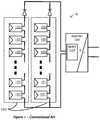
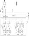
- FIG. 1A conventional installation of solar power system 10 is illustrated in FIG. 1 . Since the voltage provided by each individual solar panel 101 may be low, several panels may be connected in series to form a string of panels 103 . For a large installation, when higher current may be utilized, several strings 103 may be connected in parallel to form the overall system 10 .
- Solar panels 101may be mounted outdoors, and their leads may be connected to a maximum power point tracking (MPPT) module 107 and then to an inverter 104 .
- MPPTmaximum power point tracking
- the MPPT 107may be implemented as part of the inverter 104 .
- the harvested power from the DC sourcesmay be delivered to the inverter 104 , which converts the fluctuating direct-current (DC) into alternating-current (AC) having a desired voltage and frequency at the inverter output, which may be, e.g., I IOV or 220V at 60 Hz, or 220V at 50 Hz.
- inverters that produce 220Vmay be then split into two I IOV feeds in an electric box.
- the AC current from the inverter 104may then be used for operating electric appliances or fed to the power grid.
- the power extracted from inverter 104may be directed to a conversion and charge/discharge circuit to store the excess power created as charge in batteries. In case of a battery-tied application, the inversion stage might be skipped altogether, and the DC output of the MPPT stage 107 may be fed into the charge/discharge circuit.
- each solar panel 101supplies relatively very low voltage and current.
- a challenge facing the solar array designermay be to produce a standard AC current at 120V or 220V root-mean-square (RMS) from a combination of the low voltages of the solar panels.
- the delivery of high power from a low voltagemay utilize very high currents, which may cause large conduction losses on the order of the second power of the current (IQ).
- a power invertersuch as the inverter 104 , which may be used to convert DC current to AC current, may be most efficient when its input voltage may be slightly higher than its output RMS voltage multiplied by the square root of 2.
- the power sourcessuch as the solar panels 101 , may be combined in order to reach the correct voltage or current.
- a common methodmay be to connect the power sources in series in order to reach the desirable voltage and in parallel in order to reach the desirable current, as shown in FIG. 1 .
- a large number of the panels 101may be connected into a string 103 and the strings 103 may be connected in parallel to the power inverter 104 .
- the panels 101may be connected in series in order to reach the minimal voltage for the inverter.
- Multiple strings 103may be connected in parallel into an array to supply higher current, so as to enable higher power output.
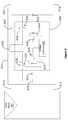
- FIG. 2illustrates an example of one serial string of DC sources, e.g., solar panels 101 a 101 d , and MPPT circuit 107 integrated with inverter 104 .
- the current versus voltage (IV) characteristicsare plotted ( 210 a - 210 d ) to the left of each DC source 101 .
- the currentdecreases as the output voltage increases. At some voltage value, the current goes to zero, and in some applications may assume a negative value, meaning that the source becomes a sink.
- Bypass diodesmay be used to prevent the source from becoming a sink.
- the powerreaches its maximum. It may be desirable to operate a power generating power source (e.g., photovoltaic panel, cell, etc.) at this maximum power point.
- a power generating power sourcee.g., photovoltaic panel, cell, etc.
- the purpose of the MPPTmay be to find this point and operate the system at this point to draw the maximum power from the sources.
- the MPPT module 107may receive the current extracted from all of the solar panels together and may track the maximum power point for this current to provide the maximum average power such that if more current is extracted, the average voltage from the panels starts to drop, thus lowering the harvested power. MPPT module 107 maintains a current that yields the maximum average power from the overall system 10 . However, since sources 101 a - 101 d may be connected in series to a single MPPT 107 , the MPPT may select a single power point, which would be somewhat of an average of the maximum power points (MPP) of each of the serially connected sources.
- MPPmaximum power points
- each string 103carries a single current that is passed through all of solar panels 101 along string 103 . If solar panels 101 are mismatched due to manufacturing differences, aging or if they malfunction or placed under different shading conditions, the current, voltage and power output of each panel may be different. Forcing a single current through all of panels 101 of string 103 may cause individual panels 101 to work at a non-optimal power point and can also cause panels 101 , which may be highly mismatched to generate “hot spots” due to the high current flowing through them.
- panels 101may be matched improperly. In some cases, external diodes may be used to bypass panels 101 that are highly mismatched.
- all strings 103may be composed of exactly the same number of solar panels and panels 101 may be selected of the same model and may be installed at exactly the same spatial orientation, being exposed to the same sunlight conditions at all times. Installation according to these constraints may be very costly.
- the installercan verify the correctness of the installation and performance of the solar array by using test equipment to check the current-voltage characteristics of each panel, each string and the entire array. In practice, however, individual panels and strings may be either not tested at all or tested only prior to connection. Current measurement may be performed by a series connection to the solar array such as with a series resistor in the array, which is typically not convenient. Instead, typically only high-level pass/fail testing of the overall installation is performed.
- the solar arraymay be connected to inverter 104 , which may include a monitoring module, which monitors performance of the entire array.
- the performance information gathered from monitoring within inverter 104may include integrated power output of the array and the power production rate, but the information lacks any fine details about the functioning of individual solar panels 101 . Therefore, the performance information provided by monitoring at the inverter 104 may be insufficient to understand if power loss may be due to environmental conditions, from malfunctions or from poor installation or maintenance of the solar array. Furthermore, integrated information may not pinpoint which of solar panels 101 are responsible for a detected power loss.
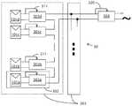
- FIG. 3illustrates a distributed power harvesting configuration 30 , according to an embodiment.
- Configuration 30enables connection of multiple power sources, for example, solar panels 101 a - 101 d , into a single power supply.
- the series string of all of the solar panelsmay be coupled to an inverter 304 .
- several serially connected strings of solar panelsmay be connected to a single inverter 304 .
- the inverter 304may be replaced by other elements, such as, e.g., a charging regulator for charging a battery bank.
- each solar panel 101 a - 101 dmay be connected to a separate power converter circuit 305 a - 305 d .
- One solar panel 101 together with its connected power converter circuitforms a module, e.g., photovoltaic module 302 (only one of which is labeled).
- Each converter 305 a - 305 dadapts optimally to the power characteristics of the connected solar panel 101 a - 101 d and transfers the power efficiently from converter input to converter output.
- the converters 305 a - 305 dmay be buck converters, boost converters, buck/boost converters, flyback or forward converters, etc.
- the converters 305 a - 305 dmay also contain a number of component converters, for example a serial connection of a buck and a boost converter.
- Each converter 305 a - 305 dmay include a control circuit 311 that receives a feedback signal, not from the converter's output current or voltage, but rather from the converter's input coming from the solar panel 101 .
- An input sensormeasures an input parameter, input power, input current and/or input voltage and sets the input power.
- An example of such a control circuitmay be a maximum power point tracking (MPPT) circuit.
- MPPTmaximum power point tracking
- a controller within converter 305monitors the voltage and current at the converter input terminals and determines the pulse width modulation (PWM) of the converter in such a way that maximum power may be extracted from the attached panel 101 a - 101 d .
- the controller of the converter 305dynamically tracks the maximum power point at the converter input.
- the feedback loop of control circuit 311may be closed on the input power in order to track maximum input power rather than closing the feedback loop on the output voltage as performed by conventional DC-to-DC voltage converters (e.g., MPPT 107 ).
- each string 303 in system 30may have a different number or different brand of panels 101 a - 101 d connected in series.
- Control circuit 311 of FIG. 3continuously maximizes power on the input of each solar panel 101 a - 101 d to react to changes in temperature, solar radiance, shading or other performance factors that impact that particular solar panel 101 a -I O 1 d .
- control circuit 311 within the converters 305 a - 305 dharvests the maximum possible power from each panel 101 a - 101 d and transfers this power as output power regardless of the parameters impacting the other solar panels.
- the embodiments shown in FIG. 3continuously track and maintain the input current and the input voltage to each converter 305 at the maximum power point of the connected DC power source.
- the maximum power of the DC power source that may be input to converter 305may be also output from converter 305 .
- the converter output powermay be at a current and voltage different from the converter input current and voltage. While maintaining the total power given the minor power loss due to inefficiency of the power conversion, the output current and output voltage from converter 305 may be responsive to requirements of the series connected portion of the circuit.
- each DC power source 101e.g. photovoltaic panel 101 may be associated with a DC-DC power converter 305 .
- Modules formed by coupling the DC power sources 101 to their associated converters 305may be coupled in series to provide a string of modules. The string of modules may be then coupled to inverter 304 having its input voltage fixed.
- a maximum power point control circuit control circuit 311 in each converter 305harvests the maximum power from each DC power source 101 and transfers this power as output from power converter 305 .
- the input powermay be converted to the output power, such that the conversion efficiency may be 95°0 or higher in some situations.
- controllingmay be performed by fixing the input current or input voltage of the converter to the maximum power point and allowing output voltage of the converter to vary.
- one or more sensorsmay monitor the input power level to the associated converter 305 .
- a microcontrollermay perform the maximum power point tracking and control in each converter 305 by using pulse width modulation to adjust the duty cycle used for transferring power from the input to the output.
- An aspectmay provide a greater degree of fault tolerance, maintenance and serviceability by monitoring, logging and/or communicating the performance of each solar panel.
- the microcontroller that may be used for maximum power point trackingmay also be used to perform the monitoring, logging and communication functions.
- arrays of solar cellsare provided where the power from the cells may be combined.
- Each converter 305may be attached to a single solar cell, or a plurality of cells connected in series, in parallel, or both, e.g., parallel connection of strings of serially connected cells.
- each converter 305may be attached to one or more panels of a photovoltaic string.
- the aspectsmay be used in any distributed power network using DC power sources.
- theymay be used in batteries with numerous cells or hybrid vehicles with multiple fuel cells on board.
- the DC power sourcesmay be solar cells, solar panels, electrical fuel cells, electrical batteries, and the like.
- the discussion belowrelates to combining power from an array of DC power sources into a source of AC voltage, the aspects may also apply to combining power from DC sources into another DC voltage.
- a controller within the convertermay monitor the current or voltage at the input, and the voltage at the output.
- the controllermay also determine the appropriate pulse width modulation (PWM) duty cycle to fix the output voltage to the predetermined value by increasing the duty cycle if the output voltage drops.
- PWMpulse width modulation
- the conventional convertermay include a feedback loop that closes on the output voltage and uses the output voltage to further adjust and fine-tune the output voltage from the converter. As a result of changing the output voltage, the current extracted from the input may be also varied.
- FIGS. 4A and 4Billustrate an operation of the system of FIG. 3 under different conditions, according to embodiments.
- An exemplary configuration 40may be similar to configuration 30 of FIG. 3 .
- ten DC power sources 101 /I through 101 / 10may be connected to ten power converters 305 /I through 305 / 10 , respectively.
- the modules formed by the DC power sources 101 and their connected converters 305may be coupled together in series to form a string 303 .
- the series-connected converters 305may be coupled to a DC-to-AC inverter 404 .
- DC power sourcesmay be solar panels 101 and the example may be discussed with respect to solar panels as one illustrative case.
- Each solar panel 101may have a different power output due to manufacturing tolerances, shading, or other factors.
- FIG. 4Aan ideal case may be illustrated in FIG. 4A , where efficiency of the DC-to-DC conversion may be assumed to be 100% and the panels 101 may be assumed to be identical. In some aspects, efficiencies of the converters may be quite high and range at about 95%-99%. So, the assumption of 100% efficiency may not be unreasonable for illustration purposes.
- each of the DC-DC converters 305may be constructed as a power converter, i.e., it transfers to its output the entire power it receives in its input with very low losses.
- Power output of each solar panel 101may be maintained at the maximum power point for the panel by a control loop 311 within the corresponding power converter 305 .
- the MPPT loopmay draw current and voltage level that will transfer the entire 200 W from the panel to its associated converter 305 . That is, the current and voltage dictated by the MPPT form the input current I in and input voltage V in to the converter.
- the output voltagemay be dictated by the constant voltage set at the inverter 404 , as will be explained below.
- the output current Ioutwould then be the total power, i.e., 200 W, divided by the output voltage Vout.
- the input voltage to load 104varies according to the available power. For example, when a lot of sunshine may be available in a solar installation, the voltage input to inverter 104 can vary even up to 1000 volts. Consequently, as sunshine illumination varies, the voltage varies with it, and the electrical components in inverter 104 (or other power supplier or load) may be exposed to varying voltage. This tends to degrade the performance of the components and may ultimately cause them to fail. On the other hand, by fixing or limiting the voltage or current to the input of the load or power supplier, e.g., inverter 304 , the electrical components may always be exposed to the same voltage or current and possibly have extended service life.
- the components of the loadmay be selected so that at the fixed input voltage or current they operate at, say, 60% of their rating. This may improve the reliability and prolong the service life of the component, which may be critical for avoiding loss of service in applications such as solar power systems.
- the input voltage to inverter 404may be controlled by inverter 404 (in this example, kept constant), by way of control loop 420 (similar to control loop 320 of inverter 304 above).
- system 40may be still maintained at an ideal mode (i.e., perfectly matching DC sources and entire power may be transferred to inverter 404 ), but the environmental conditions may different for different panels.
- one DC sourcemay be overheating, may be malfunctioning, or, as in the example of FIG. 4B , the ninth solar panel 101 / 9 may be shaded and consequently produces only 40 W of power. Since all other conditions as in the example of FIG. 4A are kept, the other nine solar panels 101 may be unshaded and still produce 200 W of power.
- the power converter 305 / 9includes MPPT to maintain the solar panel 101 / 9 operating at the maximum power point, which may be now lowered due to the shading.
- the benefit of the topology illustrated in FIGS. 4A and 4Bmay be numerous.
- the output characteristics of the serially connected DC sourcessuch as solar panels
- the serial stringmay utilize panels from different manufacturers or panels installed on different parts of the roofs (i.e., at different spatial orientation).
- the stringsmay not be necessary that the strings match; rather each string may have different panels or different number of panels.
- This topologymay also enhance reliability by alleviating the hot spot problem.
- the output of the shaded panel 101 / 9is 1.43 A, while the current at the output of the unshaded panels is 6.25 A.
- the input voltagemay be set independently, and the power draw from each panel to its converter may be set independently according to the panel's MPP at each point in time, the current at each panel may be independent on the current draw from the serially connected converters.
- inverter 404may include a control loop 420 to maintain an optimal voltage at the input of inverter 404 .
- the input voltage to inverter 404may be maintained at 400V by the control loop 420 .
- the converters 305may be transferring substantially all (e.g., >95%) of the available power from the solar panels to the input of the inverter 404 .
- the input current to the inverter 404may be dependent only on the power provided by the solar panels and the regulated set, i.e., constant, voltage at the inverter input.
- Conventional inverter 104may have a very wide input voltage to accommodate for changing conditions, for example a change in luminance, temperature and aging of the solar array. This may be in contrast to inverter 404 that may be designed according to aspects.
- the inverter 404does not utilize a wide input voltage and may be therefore simpler to design and more reliable. This higher reliability may be achieved, among other factors, by the fact that there may be no voltage spikes at the input to the inverter and thus the components of the inverter experience lower electrical stress and may last longer.
- the inverter 404may be a part of a circuit, the power from the panels may be transferred to a load that may be connected to the inverter.
- any excess power produced by the solar array, and not used by the loadmay be dissipated. Excess power may be handled by selling the excess power to the utility company if such an option is available. For off-grid solar arrays, the excess power may be stored in batteries. Yet another option may be to connect a number of adjacent houses together to form a micro-grid and to allow load-balancing of power between the houses. If the excess power available from the solar array is not stored or sold, then another mechanism may be provided to dissipate excess power.
- the features and benefits explained with respect to FIGS. 4A and 4Bstem, at least partially, from having inverter 404 control the voltage provided at its input.
- FIG. 4Cillustrates an embodiment where the inverter controls the input current.
- Power output of each solar panel 101may be maintained at the maximum power point for the panel by a control loop within the corresponding power converter 305 .
- all of the panelsmay be exposed to full sun illumination and each solar panel 101 provides 200 W of power.
- the MPPT loopwill draw current and voltage level that will transfer the entire 200 W from the panel to its associated converter. That is, the current and voltage controlled by the MPPT form the input current Iin and input voltage Vin to the converter.
- the output voltage of the convertermay be determined by the constant current set at the inverter 404 , as will be explained below.
- the output voltage Voutwould then be the total power, i.e., 200 W, divided by the output current Iout.
- the input current to inverter 404may be controlled by the inverter by way of control loop 420 . For the purpose of this example, assume the input current is kept as 5 A.
- inverter 404may be designed to keep the current or the voltage constant, then regardless of the operation of the panels, the current or voltage to inverter 404 will remain constant.
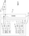
- FIG. 5illustrates a distributed power harvesting system 50 , according to other embodiments, using DC power sources.
- FIG. 5illustrates multiple strings 303 coupled together in parallel.
- Each of strings 303may be a series connection of multiple modules and each of the modules includes a DC power source 101 that may be coupled to a converter 305 .
- the DC power sourcemay be a solar panel.
- the output of the parallel connection of the strings 303may be connected, again in parallel, to a shunt regulator 506 and a load 504 .
- the load 504may be an inverter as with the embodiments of FIGS. 4A and 4B .
- Shunt regulatorsautomatically maintain a constant voltage across its terminals.
- the shunt regulator 506may be configured to dissipate excess power to maintain the input voltage at the input to the inverter 504 at a regulated level and prevent the inverter input voltage from increasing.
- the current which flows through shunt regulator 506complements the current drawn by inverter 504 in order to ensure that the input voltage of the inverter may be maintained at a constant level, for example at 400V.
- the inverter input currentmay be varied according to the available power draw. This current may be divided between the strings 303 of the series connected converters.
- the output power of converter 305may be determined.
- the converter power and the converter output current togethermay determine the converter output voltage.
- the converter output voltagemay be used by a power conversion circuit in the converter for stepping up or stepping down the converter input voltage to obtain the converter output voltage from the input voltage as determined by the MPPT.
- FIG. 6illustrates an illustrative example of DC-to-DC converter 305 according to embodiments.
- DC-to-DC convertersmay be conventionally used to either step down or step up a varied or constant DC voltage input to a higher or a lower constant voltage output, depending on the requirements of the circuit.
- the DC-DC convertermay be used as a power converter, i.e., transferring the input power to output power, the input voltage varying according to the maximum power point, while the output current being dictated by the constant input voltage to inverter 304 , 404 , or 504 . That is, the input voltage and current may vary at any time and the output voltage and current may vary at any time, depending on the operating condition of the DC power sources.
- the converter 305may be connected to a corresponding DC power source 101 (or 101 ) at input terminals 614 and 616 .
- the converted power of the DC power source 101may be output to the circuit through output terminals 610 and 612 .
- the remainder of the converter circuitmay be located that includes input and output capacitors 620 and 640 , back flow prevention diodes 622 and 642 and a power conversion circuit including a controller 606 and an inductor 608 .
- the inputs 616 and 614may be separated by a capacitor 620 , which may act as an open circuit to a DC voltage.
- the outputs 610 and 612may be also separated by a capacitor 640 that also acts as an open circuit to DC output voltage. These capacitors may be DC blocking or AC-coupling capacitors that short circuit when faced with alternating current of a frequency, which may be selectable.
- Capacitor 640 coupled between the outputs 610 and 612may also operate as a part of the power conversion circuit discussed below.
- Diode 642may be coupled between the outputs 610 and 612 with a polarity such that current may not backflow into the converter 305 from the positive lead of the output 612 .
- Diode 622may be coupled between the positive output lead 612 through inductor 608 , which acts as a short for DC current and the negative input lead 614 with such a polarity to prevent a current from the output 612 to backflow into the solar panel 101 .
- the DC power source 101may be a solar panel, solar cell, string or solar panels or a string of solar cells.
- a voltage differencemay exist between the wires 614 and 616 due to the electron-hole pairs produced in the solar cells of panel 101 .
- Converter 305may maintain maximum power output by extracting current from the solar panel 101 at its peak power point by continuously monitoring the current and voltage provided by the panel and using a maximum power point tracking algorithm.
- Controller 606may include an MPPT circuit or algorithm for performing the peak power tracking. Peak power tracking and pulse width modulation, PWM, may be performed together to achieve the desired input voltage and current.
- the MPPT in the controller 606may be any conventional MPPT, such as, e.g., perturb and observe (P&O), incremental conductance, etc.
- the MPPTmay be performed on the panel directly, i.e., at the input to the converter, rather than at the output of the converter.
- the generated powermay be then transferred to the output terminals 610 and 612 .
- the outputs of multiple converters 305may be connected in series, such that the positive lead 612 of one converter 305 may be connected to the negative lead 610 of the next converter 305 (e.g., as shown in FIG. 4 a ).
- the converter 305may be shown as a buck plus boost converter.
- the term “buck plus boost” as used hereinmay be a buck converter directly followed by a boost converter as shown in FIG. 6 , which may also appear in the literature as “cascaded buck-boost converter”. If the voltage is to be lowered, the boost portion may be shorted (e.g., FET switch 650 statically closed). If the voltage is to be raised, the buck portion may be shorted (i.e., FET switch 630 statically closed).
- the term “buck plus boost”differs from buck/boost topology, which may be a classic topology that may be used when voltage is to be raised or lowered.
- the efficiency of “buck/boost” topologymay be inherently lower than a buck plus boost converter. Additionally, for given requirements, a buck/boost converter may need bigger passive components than a buck plus boost converter in order to function. Therefore, the buck plus boost topology of FIG. 6 may have a higher efficiency than the buck/boost topology. However, the circuit of FIG. 6 may have to continuously decide whether it may be bucking (operating the buck portion) or boosting (operating the boost portion). In some situations when the desired output voltage may be similar to the input voltage, then both the buck and boost portions may be operational.
- the controller 606may include a pulse width modulator, PWM, or a digital pulse width modulator, DPWM, to be used with the buck and boost converter circuits.
- the controller 606controls both the buck converter and the boost converter and determines whether a buck or a boost operation is to be performed. In some circumstances both the buck and boost portions may operate together. That is, as explained with respect to the embodiments of FIGS. 4A and 4B , the input voltage and input current may be selected independently of the selection of output current and output voltage. Moreover, the selection of either input or output values may change at any given moment depending on the operation of the DC power sources. Therefore, in the embodiment of FIG.
- the convertermay be constructed so that at any given time a selected value of input voltage and input current may be up converted or down converted depending on the output requirement.
- an integrated circuit (IC) 604may be used that incorporates some of the functionality of converter 305 .
- IC 604may be a single ASIC able to withstand harsh temperature extremes present in outdoor solar installations.
- ASIC 604may be designed for a high mean time between failures (MTBF) of more than 25 years.
- MTBFmean time between failures
- a discrete solution using multiple integrated circuitsmay also be used in a similar manner.
- the buck plus boost portion of the converter 305may be implemented as the IC 604 . Practical considerations may lead to other segmentations of the system.
- the IC 604may include two ICs, one analog IC, which handles the high currents and voltages in the system, and one simple low-voltage digital IC, which includes the control logic.
- the analog ICmay be implemented using power FETs that may alternatively be implemented in discrete components, FET drivers, A/Ds, and the like.
- the digital ICmay form the controller 606 .
- the buck converterincludes the input capacitor 620 , transistors 628 and 630 , a diode 622 positioned in parallel to transistor 628 , and an inductor 608 .
- the transistors 628 and 630may each have a parasitic body diode 624 and 626 , respectively.
- the boost converterincludes the inductor 608 , which may be shared with the buck converter, transistors 648 and 650 , a diode 642 positioned in parallel to transistor 650 , and the output capacitor 640 .
- the transistors 648 and 650may each have a parasitic body diode 644 and 646 , respectively.
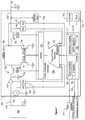
- FIG. 7illustrates another illustrative embodiment of a power converter 305 , according to embodiments.
- FIG. 7highlights, among others, a monitoring and control functionality of a DC-to-DC converter 305 , according to embodiments.
- a DC voltage source 101is also shown in the figure.
- DC-to-DC converter 305is connected to DC voltage source 101 through input 716 , and connected to output capacitor 740 through output 612 .
- Portions of a simplified buck and boost converter circuitare shown for converter 305 . The portions shown include the switching transistors 728 , 730 , 748 and 750 and the common inductor 708 . Each of the switching transistors may be controlled by a power conversion controller 706 .
- the power conversion controller 706includes the pulse-width modulation (PWM) circuit 733 , and a digital control machine 743 including a protection portion 737 .
- the power conversion controller 706may be coupled to microcontroller 790 , which includes an MPPT algorithm 719 , and may also include a communication module 709 , a monitoring and logging module 711 , and a protection module 735 .
- a current sensor 703may be coupled between the DC power source 101 and the converter 305 , and output of the current sensor 703 may be provided to the digital control machine 743 through an associated analog to digital converter 723 .
- a voltage sensor 704may be coupled between the DC power source 101 and the converter 305 and output of the voltage sensor 704 may be provided to the digital control machine 743 through an associated analog to digital converter 724 .
- the current sensor 703 and the voltage sensor 704may be used to monitor current and voltage output from the DC power source, e.g., the solar panel 101 .
- the measured current and voltagemay be provided to the digital control machine 743 and may be used to maintain the converter input power at the maximum power point.
- the PWM circuit 733controls the switching transistors of the buck and boost portions of the converter circuit.
- the PWM circuitmay be a digital pulse-width modulation (DPWM) circuit.
- Outputs of the converter 305 taken at the inductor 708 and at the switching transistor 750may be provided to the digital control machine 743 through analog to digital converters 741 , 742 , so as to control the PWM circuit 733 .
- DPWMdigital pulse-width modulation
- a random access memory (RAM) module 715 and a non-volatile random access memory (NVRAM) module 713may be located outside the microcontroller 790 but coupled to the microcontroller 790 .
- a temperature sensor 779 and one or more external sensor interfaces 707may be coupled to the microcontroller 790 .
- the temperature sensor 779may be used to measure the temperature of the DC power source 101 .
- a physical interface 717may be coupled to the microcontroller 790 and used to convert data from the microcontroller into a standard communication protocol and physical layer.
- An internal power supply unit 739may be included in the converter 305 .
- the current sensor 703may be implemented by various techniques used to measure current.
- the current measurement module 703may be implemented using a very low value resistor. The voltage across the resistor will be proportional to the current flowing through the resistor.
- the current measurement module 703may be implemented using current probes, which use the Hall Effect to measure the current through a conductor without adding a series resistor. After translating the current measurement to a voltage signal, the data may be passed through a low pass filter and then digitized. The analog to digital converter associated with the current sensor 703 may be shown as the A/D converter 723 in FIG. 7 . Aliasing effect in the resulting digital data may be avoided by selecting an appropriate resolution and sample rate for the analog to digital converter. If the current sensing technique does not utilize a series connection, then the current sensor 703 may be connected to the DC power source 101 in parallel.
- the voltage sensor 704uses simple parallel voltage measurement techniques in order to measure the voltage output of the solar panel.
- the analog voltagemay be passed through a low pass filter in order to minimize aliasing.
- the datamay be then digitized using an analog to digital converter.
- the analog to digital converter associated with the voltage sensor 704may be shown as the A/D converter 724 in FIG. 7 .
- the A/D converter 724has sufficient resolution to generate an adequately sampled digital signal from the analog voltage measured at the DC power source 101 that may be a solar panel.
- the current and voltage data collected for tracking the maximum power point at the converter inputmay be used for monitoring purposes also.
- An analog to digital converter with sufficient resolutionmay correctly evaluate the panel voltage and current. However, to evaluate the state of the panel, even low sample rates may be sufficient.
- a low-pass filtermakes it possible for low sample rates to be sufficient for evaluating the state of the panel.
- the current and voltage datamay be provided to the monitoring and logging module 711 for analysis.
- Temperature sensor 779enables the system to use temperature data in the analysis process.
- the temperaturemay be indicative of some types of failures and problems.
- the panel temperaturemay be a factor in power output production.
- the one or more optional external sensor interfaces 707enable connecting various external sensors to the converter 305 .
- External sensors 707may be used to enhance analysis of the state of the solar panel 101 , or a string or an array formed by connecting the solar panels 101 .
- Examples of external sensors 707include ambient temperature sensors, solar radiance sensors, and sensors from neighboring panels.
- External sensorsmay be integrated into the converter 305 instead of being attached externally.
- the information acquired from the current and voltage sensors 703 , 704 and the optional temperature and external sensors 707may be transmitted to a central analysis station for monitoring, control, and analysis using the communications interface 709 .
- the central analysis stationis not shown in the figure.
- the communication interface 709connects a microcontroller 790 to a communication bus.
- the communication buscan be implemented in several ways. In one embodiment, the communication bus may be implemented using an off-the-shelf communication bus such as Ethernet or RS422. Other methods such as wireless communications or power line communications, which could be implemented on the power line connecting the panels, may also be used. If bidirectional communication is used, the central analysis station may request the data collected by the microcontroller 790 . Alternatively or in addition, the information acquired from sensors 703 , 704 , 707 may be logged locally using the monitoring and logging module 711 in local memory such as the RAM 715 or the NVRAM 713 .
- Analysis of the information from sensors 703 , 704 , 707enables detection and location of many types of failures associated with power loss in solar arrays. Smart analysis can also be used to suggest corrective measures such as cleaning or replacing a specific portion of the solar array. Analysis of sensor information can also detect power losses caused by environmental conditions or installation mistakes and prevent costly and difficult solar array testing.
- the microcontroller 790simultaneously maintains the maximum power point of input power to the converter 305 from the attached DC power source or solar panel 101 based on the MPPT algorithm in the MPPT module 719 , and manages the process of gathering the information from sensors 703 , 704 , 707 .
- the collected informationmay be stored in the local memory 713 , 715 and transmitted to an external central analysis station.
- the microcontroller 790may use previously defined parameters stored in the NVRAM 713 in order to operate converter 305 .
- the information stored in the NVRAM 713may include information about the converter 305 such as serial number, the type of communication bus used, the status update rate and the ID of the central analysis station. This information may be added to the parameters collected by the sensors before transmission.
- Converters 305may be installed during the installation of the solar array or retrofitted to existing installations. In both cases, converters 305 may be connected to a panel junction connection box or to cables connecting the panels 101 . Each converter 305 may be provided with the connectors and cabling to enable easy installation and connection to solar panels 101 and panel cables.
- physical interface 717may be used to convert to a standard communication protocol and physical layer so that during installation and maintenance, the converter 305 may be connected to one of various data terminals, such as a computer or PDA. Analysis may then be implemented as software, which will be run on a standard computer, an embedded platform or a proprietary device.
- the installation process of converters 305may include connecting each converter 305 to a solar panel 101 .
- One or more of sensors 703 , 704 , 707may be used to ensure that the solar panel 101 and the converter 305 may be properly coupled together.
- parameterssuch as serial number, physical location and the array connection topology may be stored in the NVRAM 713 . These parameters may be used by analysis software to detect future problems in solar panels 101 and arrays.
- the DC power sources 101are solar panels
- one of the problems facing installers of photovoltaic solar panel arraysmay be safety.
- the solar panels 101may be connected in series during the day when there may be sunlight. Therefore, at the final stages of installation, when several solar panels 101 may be connected in series, the voltage across a string of panels may reach dangerous levels. Voltages as high as 600V may be common in domestic installations. Thus, the installer faces a danger of electrocution.
- the converters 305 that may be connected to the panels 101may use built-in functionality to prevent such a danger.
- the converters 305may include circuitry or hardware of software safety module that limits the output voltage to a safe level until a predetermined minimum load may be detected.
- Another method of providing a safety mechanismmay be to use communications between the converters 305 and the associated inverter for the string or array of panels. This communication, that may be for example a power line communication, may provide a handshake before any significant or potentially dangerous power level may be made available. Thus, the converters 305 would wait for an analog or digital release signal from the inverter in the associated array before transferring power to inverter.
- the above methodology for monitoring, control and analysis of the DC power sources 101may be implemented on solar panels or on strings or arrays of solar panels or for other power sources such as batteries and fuel cells.
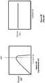
- FIG. 8Aillustrates graphically behavior of power output in FIG. 2 from solar panels 101 (and which is input to inverter module 104 ) as a function of current in conventional system 10 .
- Powerincreases approximately linearly until a current at which a maximum power point MPP may be found which may be some average over the MPP points of all connected solar panels 101 .
- Conventional MPPT module 107locks (e.g., converges) on to the maximum power point.
- FIG. 8Billustrates graphically power input or power output versus output current from series/parallel connected modules 302 or strings 303 ( FIG. 3 ). It may be readily seen that by virtue of control circuit 311 in modules 302 , power as a function of current output may be approximately constant. Similarly, power as a function of voltage output may be approximately constant. It is desirable and it would be advantageous to have a system in which modules 302 and/or string 303 of FIG. 3 operate with the conventional inverter 104 equipped with an MPPT module 107 of FIG. 2 . However, as shown in FIG.
- MPPT 107does not have a maximum power peak (versus current or voltage) on which to lock on to and MPPT circuit 107 may become unstable with varying or oscillating current/voltage at the input of inverter module 104 .
- a maximum power at an output voltage or current at least for a time periodmay be output or presented to conventional inverter module 104 equipped with MPPT module 107 according to various aspects.
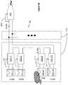
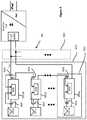
- FIG. 8Cillustrates in a simplified block diagram of a photovoltaic distributed power harvesting system 80 including photovoltaic panels 101 a 101 d connected respectively to power converter circuits 305 a - 305 d .
- Solar panel 101together with its associated power converter circuit 305 forms photovoltaic module 302 .
- Each converter 305 a - 305 dadapts to the power characteristics of the connected solar panel 101 a - 101 d and transfers the power efficiently from converter input to converter output.
- Each converter 305 a - 305 dincludes control circuit 311 that receives a feedback signal from the input from solar panel 101 .
- Control circuit 311may be a maximum power point tracking (MPPT) control loop.
- MPPTmaximum power point tracking
- System 80includes a series and/or parallel connection between outputs of strings 303 and the input of a conventional inverter 104 with an integrated MPPT module 107 .
- Inverter 104 with integrated MPPT module 107is designed to be connected directly to the outputs with series/parallel connections of conventional solar panels 101 as in conventional system 10 of FIG. 1 .
- MPPT algorithm 719 of microcontroller 790 in converters 305may, in various embodiments, provide a slight maximum input power at a predetermined output voltage or current or conversion ratio into MPPT 107 .
- the input power into MPPT 107may be maximized at a predetermined value of output voltage or current.
- the maximum at the predetermined maximum power pointmay be very slight with a total variation of just a few percent to several percent over the entire input range of current or voltage of inverter 104 .
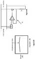
- a circuit, 81 disposed between panels 101 or strings 303 and inverter 104may be used to present to MPPT module 107 with a maximum power point onto which to lock (e.g., converge).
- Circuit 81may be a power attenuator interposed between parallel-connected strings 303 and MPPT module 107 .
- Circuit 81may include a non-linear current sink “f” configured to draw a small amount of current at a particular voltage or voltage range from the DC power line connecting strings 303 to MPPT module 107 .
- the output of current sink “f”may be fed into the positive input of operational amplifier A 1 .
- the output of operational amplifier A 1feeds the base of transistor T 1 , the emitter of which may be connected and fed back to the negative input of operational amplifier A 1 .
- the collector of transistor T 1connects to the positive DC power line.
- the negative DC power linemay be connected to the emitter of transistor T 1 through a shunt resistor Rs.
- FIG. 8Fillustrates a simplified method for operating modules 302 and/or strings 303 with inverter 104 equipped with an MPPT module 107 .
- the output voltage of power converter 305is sensed (step 801 ) across output terminals 610 and 612 .
- Control circuit 311may be configured to set (step 803 ) the input power received at the input terminals 614 / 616 to a maximum power for a predetermined output voltage point or voltage range or at a predetermined output current point or current range.
- the predetermined valuesmay be stored in memory 713 and/or 715 or may be received through communications interface 709 .
- the control circuitmay be configured to set (step 803 ) the input power received at the input terminals to less than the maximum available power (i.e., decrease the input power in response to the difference between the output current and the predetermined current increasing, and increase the input power towards the maximum available power in response to the difference between the output current and the predetermined current decreasing).
- the predetermined output current valuesmay be selected such that the output power of module 302 or string 303 is as shown in FIG. 8D .
- the predetermined output voltage values versus output powermay be selected in a similar way. While FIG.
- MPPT module 107may present MPPT module 107 with other output power versus current (or voltage) curves that have one or more local maximum to which the MPPT 107 can track and lock (e.g., converge).
- maximum power point tracking circuit 107if present, may stably track (step 805 ) the voltage and/or current point or range.
- MPPT tracking circuit 107locks (step 809 ) onto the power point (e.g., the “predetermined point” in FIG. 8D ).
- FIG. 9illustrates in a simplified block diagram a photovoltaic distributed power harvesting system 90 including photovoltaic panels 101 a 101 d connected respectively to power converter circuits 905 a - 905 d .
- One solar panel 101 together with its associated connected power converter circuit 905forms a photovoltaic module 902 .
- Each converter 905 a - 905 dadapts to the power characteristics of the connected solar panel 905 a - 905 d and transfers the power efficiently from converter input to converter output.
- Each converter 905 a - 905 dincludes a control circuit 900 that receives a feedback signal from input sensor 904 . Specifically, input current sensors and/or voltage sensors 904 are used to provide the feedback to control circuit 900 . Control circuit 900 may also receive a signal from output current and/or output voltage sensors 906 .
- Inverter 104 with integrated MPPT module 107is designed to be connected directly to the outputs with series/parallel connections of conventional solar panels 101 as in conventional system 10 of FIG. 1 .
- photovoltaic modules 902may be designed to be integrated with inverters 304 it may be advantageous that each panel module 902 may also be integrated with a respective conventional inverter (similar to inverter 104 ) between the converter 905 output and the serially connected outputs of module 902 (not illustrated).
- System 90includes a series and/or parallel connection between outputs of strings 903 input to a conventional inverter 104 with an integrated MPPT module 107 .
- FIG. 8Gillustrates another method 821 for operating modules 902 , and/or strings 903 with inverter 104 equipped with an MPPT module 107 .
- a scanis made by control circuit 900 making a variation of the voltage conversion ratio between input voltage and output voltage (Vout) of a power converter circuit 905 .
- multiple measurementsmay be made (step 825 ) of the input and/or output power (e.g., by measuring input and output current and voltage) of converter 905 for different voltage conversion ratios that are set by control circuit 900 during the variation.
- the power measurements made for each different voltage conversion ratiomay then be used to determine (step 827 ) the maximum power point of the connected photovoltaic source.
- the voltage conversion ratio for the maximum pointmay be used to set (step 829 ) the conversion ratio for a continued operation of converter 905 .
- the continued operation of converter 905continues for a time period (step 831 ) before applying another variation of the voltage conversion ratio in step 823 .
- Power converter 905may control output voltage by varying (step 811 ) the output voltage from power converter 905 .
- the input voltage to power converter 905may be maintained at the maximum power point.
- the conversion ratio defined as the ratio of input voltage to output voltagemay be varied or perturbed to slowly approach (step 811 ) maximum power on the output terminals.
- the term “slowly” as used hereinis relative to the response time of MPPT circuit 107 associated with load 104 .
- the conversion ratio or output voltagemay be selected.
- the efficiency of the convertercan be adjusted, thereby increasing or decreasing the output power for a received input power.
- the outputcan be adjusted to increase the output power to provide a maximum power point for MPPT 107 (e.g., predetermined point in FIG. 81 )).
- MPPT circuit 107Since the output power from power converter 905 approaches slowly maximum power, MPPT circuit 107 responds accordingly and locks onto the output voltage at maximum output power. Referring now to FIG. 9 b , in the meantime MPPT circuit 107 associated with load 104 tracks the slow variation of output power from photovoltaic modules 902 . In FIG. 9 c , a graph is shown which indicates the slow variation of output power from photovoltaic modules 902 , which varies typically over many seconds (DT).
- the processes of 9 a and 9 bmay be performed in conjunction with other previously described embodiments to move the maximum power point presented to the inputs of MPPT circuit 107 .
- the maximum point illustrated in FIG. 81 ) or (other maximum point)may be shifted to a different current and/or voltage such that maximum power is maintained over changing power production and conversion conditions (e.g., light, temperature, faults, etc.) of systems 30 / 40 / 50 / 80 / 90 .
- the rate of adapting the systemis slower than the tracking rate of MPPT 107 , such that the MPPT maintains lock (e.g., convergence) on the current/voltage/power at its input of inverter 104 within the power peak (e.g., the “maximum point” in FIG. 81 )).
- FIGS. 10A and 10Billustrate another process that allows systems 30 / 90 to be integrated with inverter 104 equipped with MPPT circuit 107 .
- MPPT circuit 107perturbs (step 191 ) voltage or current across string 303 .
- Control circuit 900senses (step 195 ) the voltage or current perturbation of MPPT circuit 107 .
- Control circuit 900via sensor 906 in step 197 slowly maximizes output power at a particular voltage conversion ratio of converter 905 . Input power from a photovoltaic panel 101 may be maximized.
- decision block 817a maximum output power is being reached and in step 193 MPPT 107 locks onto the maximum output power.
Landscapes
- Engineering & Computer Science (AREA)
- Power Engineering (AREA)
- Life Sciences & Earth Sciences (AREA)
- Sustainable Development (AREA)
- Sustainable Energy (AREA)
- Physics & Mathematics (AREA)
- Electromagnetism (AREA)
- General Physics & Mathematics (AREA)
- Radar, Positioning & Navigation (AREA)
- Automation & Control Theory (AREA)
- Control Of Electrical Variables (AREA)
Abstract
Description
Claims (24)
Priority Applications (5)
| Application Number | Priority Date | Filing Date | Title |
|---|---|---|---|
| US15/831,850US10705551B2 (en) | 2012-05-25 | 2017-12-05 | Circuit for interconnected direct current power sources |
| US16/899,107US11334104B2 (en) | 2012-05-25 | 2020-06-11 | Circuit for interconnected direct current power sources |
| US17/722,479US11740647B2 (en) | 2012-05-25 | 2022-04-18 | Circuit for interconnected direct current power sources |
| US18/339,442US12306653B2 (en) | 2012-05-25 | 2023-06-22 | Circuit for interconnected direct current power sources |
| US19/018,269US20250147535A1 (en) | 2012-05-25 | 2025-01-13 | Circuit for Interconnected Direct Current Power Sources |
Applications Claiming Priority (4)
| Application Number | Priority Date | Filing Date | Title |
|---|---|---|---|
| US201261651834P | 2012-05-25 | 2012-05-25 | |
| PCT/US2013/042354WO2013177360A1 (en) | 2012-05-25 | 2013-05-23 | Circuit for interconnected direct current power sources |
| US201414401049A | 2014-11-13 | 2014-11-13 | |
| US15/831,850US10705551B2 (en) | 2012-05-25 | 2017-12-05 | Circuit for interconnected direct current power sources |
Related Parent Applications (3)
| Application Number | Title | Priority Date | Filing Date |
|---|---|---|---|
| PCT/US2013/042354ContinuationWO2013177360A1 (en) | 2012-05-25 | 2013-05-23 | Circuit for interconnected direct current power sources |
| US14/401,049ContinuationUS9870016B2 (en) | 2012-05-25 | 2013-05-23 | Circuit for interconnected direct current power sources |
| US201414401049AContinuation | 2012-05-25 | 2014-11-13 |
Related Child Applications (1)
| Application Number | Title | Priority Date | Filing Date |
|---|---|---|---|
| US16/899,107ContinuationUS11334104B2 (en) | 2012-05-25 | 2020-06-11 | Circuit for interconnected direct current power sources |
Publications (2)
| Publication Number | Publication Date |
|---|---|
| US20180224877A1 US20180224877A1 (en) | 2018-08-09 |
| US10705551B2true US10705551B2 (en) | 2020-07-07 |
Family
ID=49624334
Family Applications (6)
| Application Number | Title | Priority Date | Filing Date |
|---|---|---|---|
| US14/401,049Active2034-02-05US9870016B2 (en) | 2012-05-25 | 2013-05-23 | Circuit for interconnected direct current power sources |
| US15/831,850ActiveUS10705551B2 (en) | 2012-05-25 | 2017-12-05 | Circuit for interconnected direct current power sources |
| US16/899,107ActiveUS11334104B2 (en) | 2012-05-25 | 2020-06-11 | Circuit for interconnected direct current power sources |
| US17/722,479ActiveUS11740647B2 (en) | 2012-05-25 | 2022-04-18 | Circuit for interconnected direct current power sources |
| US18/339,442ActiveUS12306653B2 (en) | 2012-05-25 | 2023-06-22 | Circuit for interconnected direct current power sources |
| US19/018,269PendingUS20250147535A1 (en) | 2012-05-25 | 2025-01-13 | Circuit for Interconnected Direct Current Power Sources |
Family Applications Before (1)
| Application Number | Title | Priority Date | Filing Date |
|---|---|---|---|
| US14/401,049Active2034-02-05US9870016B2 (en) | 2012-05-25 | 2013-05-23 | Circuit for interconnected direct current power sources |
Family Applications After (4)
| Application Number | Title | Priority Date | Filing Date |
|---|---|---|---|
| US16/899,107ActiveUS11334104B2 (en) | 2012-05-25 | 2020-06-11 | Circuit for interconnected direct current power sources |
| US17/722,479ActiveUS11740647B2 (en) | 2012-05-25 | 2022-04-18 | Circuit for interconnected direct current power sources |
| US18/339,442ActiveUS12306653B2 (en) | 2012-05-25 | 2023-06-22 | Circuit for interconnected direct current power sources |
| US19/018,269PendingUS20250147535A1 (en) | 2012-05-25 | 2025-01-13 | Circuit for Interconnected Direct Current Power Sources |
Country Status (4)
| Country | Link |
|---|---|
| US (6) | US9870016B2 (en) |
| EP (3) | EP3499695B1 (en) |
| CN (3) | CN108306333B (en) |
| WO (1) | WO2013177360A1 (en) |
Cited By (4)
| Publication number | Priority date | Publication date | Assignee | Title |
|---|---|---|---|---|
| US11791633B2 (en) | 2011-07-11 | 2023-10-17 | Generac Power Systems, Inc. | Systems and methods for increasing output current quality, output power, and reliability of grid-interactive inverters |
| US20230378760A1 (en)* | 2015-11-19 | 2023-11-23 | Sigmagen Inc. | Multi-modal maximum power point tracking optimization solar photovoltaic system |
| EP4465472A1 (en)* | 2023-05-11 | 2024-11-20 | Huawei Digital Power Technologies Co., Ltd. | Photovoltaic inverter and control method thereof, and photovoltaic system |
| US12306653B2 (en) | 2012-05-25 | 2025-05-20 | Solaredge Technologies Ltd. | Circuit for interconnected direct current power sources |
Families Citing this family (41)
| Publication number | Priority date | Publication date | Assignee | Title |
|---|---|---|---|---|
| US10615607B2 (en)* | 2013-05-01 | 2020-04-07 | Tigo Energy, Inc. | Systems and methods for quick dissipation of stored energy from input capacitors of power inverters |
| GB2522201B (en)* | 2014-01-15 | 2018-06-27 | Nidec Control Techniques Ltd | Method and system for controlling a power output of an inverter |
| DE102014100690A1 (en)* | 2014-01-22 | 2015-07-23 | Sma Solar Technology Ag | INVERTER, PARTICULARLY AS PART OF AN ENERGY PRODUCTION ASSOCIATION, AND METHOD |
| US10069306B2 (en)* | 2014-02-21 | 2018-09-04 | Solarlytics, Inc. | System and method for managing the power output of a photovoltaic cell |
| US10770893B2 (en)* | 2014-05-02 | 2020-09-08 | The Governing Council Of The University Of Toronto | Multi-port converter structure for DC/DC power conversion |
| US10135362B2 (en)* | 2014-07-14 | 2018-11-20 | Alexander Philip Davies | Method for controlling a power conversion system |
| WO2016191264A1 (en)* | 2015-05-22 | 2016-12-01 | Tigo Energy, Inc. | Systems and methods for quick dissipation of stored energy from input capacitors of power inverters |
| US11108230B2 (en) | 2015-11-20 | 2021-08-31 | Galvion Soldier Power, Llc | Power manager with reconfigurable power converting circuits |
| US10848067B2 (en)* | 2015-11-20 | 2020-11-24 | Galvion Soldier Power, Llc | Power manager with reconfigurable power converting circuits |
| US11258366B2 (en) | 2015-11-20 | 2022-02-22 | Galvion Soldier Power, Llc | Power manager with reconfigurable power converting circuits |
| CN105387569B (en)* | 2015-11-30 | 2019-03-05 | 珠海格力电器股份有限公司 | photovoltaic air conditioning system control method and device |
| CN105406729A (en)* | 2015-12-21 | 2016-03-16 | 付强 | Voltage boosting system and control method thereof |
| TWI647900B (en)* | 2016-03-16 | 2019-01-11 | 邱煌仁 | Inverter device and controlling method thereof |
| US10236688B2 (en)* | 2016-09-26 | 2019-03-19 | City University Of Hong Kong | Method for regulating an electrical power circuit and an electrical power regulating apparatus |
| DE102016218516A1 (en)* | 2016-09-27 | 2018-03-29 | Robert Bosch Gmbh | An electrical energy storage system comprising a cross-connection of a plurality of parallel energy storage strands electrically connected via a diode to a current detection means, and a method for detecting a conduction fault |
| US11183839B2 (en) | 2016-10-10 | 2021-11-23 | Igrenenergi, Inc. | DC-DC power conversion system |
| CN108336753B (en)* | 2017-01-20 | 2023-01-06 | 丰郅(上海)新能源科技有限公司 | Photovoltaic power generation system and method for realizing output power maximization |
| IT201700032303A1 (en)* | 2017-03-23 | 2018-09-23 | St Microelectronics Srl | OPERATING PROCEDURE OF PHOTOVOLTAIC GENERATORS, CIRCUIT, DEVICE AND CORRESPONDENT SYSTEM |
| CN106992540B (en)* | 2017-04-20 | 2019-09-03 | 中南大学 | A photovoltaic system without communication power optimizer and its open circuit fault diagnosis method |
| TWI633409B (en)* | 2017-04-20 | 2018-08-21 | 台達電子工業股份有限公司 | Maximum power point tracking method and system thereof |
| US10965126B2 (en)* | 2017-05-01 | 2021-03-30 | Futurewei Technologies, Inc. | Systems and methods for control of photovoltaic arrays |
| CN109217806A (en)* | 2017-07-03 | 2019-01-15 | 北京信邦同安电子有限公司 | The split type power optimization mould group of solar components |
| US11139670B2 (en)* | 2017-08-14 | 2021-10-05 | Richtek Technology Corporation | Charger circuit with temperature compensation function and controller circuit thereof |
| CN109787213B (en)* | 2017-11-13 | 2022-10-14 | 丰郅(上海)新能源科技有限公司 | Power supply system and implementation method thereof |
| CN109830948B (en)* | 2017-11-23 | 2023-01-06 | 丰郅(上海)新能源科技有限公司 | Power processing system and power processing method |
| CN109327044B (en)* | 2018-04-23 | 2021-07-09 | 矽力杰半导体技术(杭州)有限公司 | Power conversion circuit, inverter circuit, photovoltaic power generation system and control method thereof |
| US10992139B1 (en)* | 2018-09-20 | 2021-04-27 | Farid Dibachi | Electrical power system |
| CN109193777B (en)* | 2018-10-12 | 2022-05-24 | 阳光电源股份有限公司 | Power optimizer and photovoltaic power generation system |
| US11081961B2 (en)* | 2018-11-06 | 2021-08-03 | Taiyo Yudenco., Ltd. | Power convertor, power generation system, and power generation control method |
| CN110677120B (en)* | 2018-12-27 | 2021-11-02 | 台达电子企业管理(上海)有限公司 | Photovoltaic inverter system and control method thereof |
| US11502533B2 (en)* | 2019-02-13 | 2022-11-15 | Intrinsix Corp. | Power conveyor devices for energy harvesting systems and methods thereof |
| US11415623B2 (en)* | 2019-03-28 | 2022-08-16 | Teradyne, Inc. | Test system supporting reverse compliance |
| US11190023B2 (en)* | 2019-04-23 | 2021-11-30 | Delta Electronics (Shanghai) Co., Ltd. | Photovoltaic inverter system and method for controlling the same |
| US11128142B2 (en) | 2019-04-23 | 2021-09-21 | Delta Electronics (Shanghai) Co., Ltd. | Photovoltaic power generation system and method for controlling the same |
| US11070141B2 (en) | 2019-12-23 | 2021-07-20 | King Abdulaziz University | Hybrid multilevel inverter topology with reduced switch count and dc voltage sources |
| CN111668868A (en) | 2020-05-08 | 2020-09-15 | 华为技术有限公司 | A photovoltaic power generation system and method |
| US12155263B2 (en) | 2021-08-06 | 2024-11-26 | Galvion Ltd. | Helmet-mounted power system |
| USD1062615S1 (en) | 2021-12-21 | 2025-02-18 | Galvion Soldier Power, Llc | Power pack |
| WO2023152749A1 (en)* | 2022-02-13 | 2023-08-17 | Aquarius Engines (A.M.) Ltd. | Systems and methods thereof for powering a load from a plurality of power supplies |
| US12326707B2 (en) | 2022-05-16 | 2025-06-10 | Galvion Ltd. | Method and system of providing a uniform messaging platform in a heterogeneous environment |
| US20230402665A1 (en)* | 2022-06-14 | 2023-12-14 | GM Global Technology Operations LLC | Solar charging using adjustable secondary battery |
Citations (476)
| Publication number | Priority date | Publication date | Assignee | Title |
|---|---|---|---|---|
| US2758219A (en) | 1955-05-25 | 1956-08-07 | Frank N Miller | Single-control variable phase-shift network |
| US3369210A (en) | 1965-07-28 | 1968-02-13 | Electro Nite | Electrical connector |
| US3596229A (en) | 1969-04-28 | 1971-07-27 | Wago Kontakttechnik Gmbh | Electrical connector |
| US3958136A (en) | 1974-08-09 | 1976-05-18 | Bell Telephone Laboratories, Incorporated | Level shifter circuit |
| US4060757A (en) | 1976-09-17 | 1977-11-29 | General Electric Co. | Inverters having a transformer-coupled commutating circuit |
| US4101816A (en) | 1976-11-03 | 1978-07-18 | Vibra-Metrics, Inc. | Switch control system |
| US4146785A (en) | 1978-02-13 | 1979-03-27 | Sunpower Systems Corporation | Sun-tracking control system for solar collector |
| US4161771A (en) | 1977-07-25 | 1979-07-17 | Gulton Industries, Inc. | Inverter ripple regulator |
| US4171861A (en) | 1976-08-18 | 1979-10-23 | Wago-Kontakttechnik Gmbh | Electrical distribution and/or connection device |
| US4257087A (en) | 1979-04-02 | 1981-03-17 | California Institute Of Technology | DC-to-DC switching converter with zero input and output current ripple and integrated magnetics circuits |
| US4296461A (en) | 1979-01-29 | 1981-10-20 | Duracell International Inc. | Battery package with DC to DC converter |
| US4346341A (en) | 1981-03-02 | 1982-08-24 | General Electric Company | Method and apparatus for automatic voltage reduction control |
| US4452867A (en) | 1983-02-28 | 1984-06-05 | Pittway Corporation | Storage battery containing voltage reducing means |
| US4460232A (en) | 1982-05-24 | 1984-07-17 | Amp, Incorporated | Junction box for solar modules |
| US4481654A (en) | 1982-09-09 | 1984-11-06 | General Electric Company | X-Ray tube bias supply |
| US4549254A (en) | 1983-02-03 | 1985-10-22 | Chrysler Corporation | Buck-boost regulated D.C. to D.C. power supply |
| US4554515A (en) | 1984-07-06 | 1985-11-19 | At&T Laboratories | CMOS Operational amplifier |
| JPS6165320A (en) | 1984-09-06 | 1986-04-03 | Toshiba Corp | Solar power system |
| US4598330A (en) | 1984-10-31 | 1986-07-01 | International Business Machines Corporation | High power direct current switching circuit |
| US4602322A (en) | 1984-04-02 | 1986-07-22 | Hewlett-Packard Company | Transistor rectifier |
| US4623753A (en) | 1983-10-31 | 1986-11-18 | Amp Incorporated | Watertight junction box |
| US4637677A (en) | 1984-12-18 | 1987-01-20 | Amp Incorporated | Electrical connector |
| US4639844A (en) | 1982-09-13 | 1987-01-27 | Venus Scientific Inc. | Resonant current driven power source for low input voltages |
| US4641079A (en) | 1984-02-20 | 1987-02-03 | Nippondenso Co., Ltd. | Battery voltage regulating system |
| US4641042A (en) | 1984-05-25 | 1987-02-03 | Kabushiki Kaisha Toshiba | Power supply system and a control method thereof |
| US4644458A (en) | 1984-03-19 | 1987-02-17 | Nec Corporation | Electric power supply circuit capable of reducing a loss of electric power |
| US4652770A (en) | 1984-12-18 | 1987-03-24 | Mitsubishi Denki Kabushiki Kaisha | Power source device for a load with a stand-by power supply system |
| US4685040A (en) | 1985-12-06 | 1987-08-04 | General Electric Company | Integrated circuit for controlling power converter by frequency modulation and pulse width modulation |
| US4686617A (en) | 1986-06-06 | 1987-08-11 | Rca Corporation | Current limited constant frequency dc converter |
| US4706181A (en) | 1987-02-02 | 1987-11-10 | Unisys Corporation | Switching converter with enhanced voltage clamping and energy recovery |
| US4720667A (en) | 1986-06-20 | 1988-01-19 | Lee Fred C | Zero-current switching quasi-resonant converters operating in a full-wave mode |
| US4720668A (en) | 1986-06-20 | 1988-01-19 | Lee Fred C | Zero-voltage switching quasi-resonant converters |
| US4783728A (en) | 1986-04-29 | 1988-11-08 | Modular Power Corp. | Modular power supply with PLL control |
| US4864213A (en) | 1987-12-11 | 1989-09-05 | Nec Corporation | DC supply having low and high constant voltages for powering a polarity inverter controller |
| USRE33057E (en) | 1980-06-23 | 1989-09-12 | Brigham Young University | High frequency supply system for gas discharge lamps and electronic ballast therefor |
| US4868379A (en) | 1988-06-20 | 1989-09-19 | Utility Power Group | Photovoltaic array with two-axis power maximization tracking |
| US4888063A (en) | 1985-11-21 | 1989-12-19 | Powell Roger A | Variable aperture, variable flux density, aerospace solar collector |
| US4888702A (en) | 1987-08-20 | 1989-12-19 | Integrated Power Corporation | Photovoltaic system controller |
| US4899269A (en) | 1988-01-29 | 1990-02-06 | Centre National D'etudes Spatiales | System for regulating the operating point of a direct current power supply |
| US4903851A (en) | 1988-07-07 | 1990-02-27 | Slough Donovan L | Molded plastic stud box support and box |
| US4906859A (en) | 1987-11-30 | 1990-03-06 | Nec Corporation | Power supply circuit with symmetrically tapped auto-transformer |
| US4910518A (en) | 1987-07-16 | 1990-03-20 | Samsun Semiconductor and Telecommunications Co., Ltd. | Comparator unit for a flash analog-to-digital converter |
| US4978870A (en) | 1989-07-19 | 1990-12-18 | Industrial Technology Research Institute | CMOS digital level shifter circuit |
| US4987360A (en) | 1988-12-27 | 1991-01-22 | Bill's Ice Cream, Inc. | Self-contained rechargeable battery power source with voltage reducer |
| EP0419093A2 (en) | 1989-09-20 | 1991-03-27 | Kabushiki Kaisha Toshiba | Current sensing circuit |
| EP0420295A1 (en) | 1986-03-14 | 1991-04-03 | Itron, Inc. | An RF transponder for use in an automatic/remote instrument monitoring system |
| US5045988A (en) | 1990-07-31 | 1991-09-03 | Eaton Corporation | Isolated adjustable frequency AC inverter control |
| US5081558A (en) | 1990-02-02 | 1992-01-14 | Northrop Corporation | High voltage DC relays |
| US5191519A (en) | 1991-03-27 | 1993-03-02 | Kabushiki Kaisha Toshiba | Current sharing control in a parallel inverter system |
| WO1993013587A1 (en) | 1991-12-24 | 1993-07-08 | Siemens Electric Limited | Modular ac drive controller |
| US5280232A (en) | 1990-11-30 | 1994-01-18 | Robert Bosch Gmbh | Method and apparatus for voltage regulation depending on battery charge |
| US5287261A (en) | 1992-06-23 | 1994-02-15 | The Texas A&M University System | Power conversion using zero current soft switching |
| US5289361A (en) | 1991-01-16 | 1994-02-22 | Vlt Corporation | Adaptive boost switching preregulator and method |
| US5327071A (en) | 1991-11-05 | 1994-07-05 | The United States Of America As Represented By The Administrator Of The National Aeronautics & Space Administration | Microprocessor control of multiple peak power tracking DC/DC converters for use with solar cell arrays |
| EP0604777A1 (en) | 1992-12-28 | 1994-07-06 | Motorola, Inc. | Data transmission device system and method |
| US5345375A (en) | 1991-12-16 | 1994-09-06 | Regents Of The University Of Minnesota | System and method for reducing harmonic currents by current injection |
| US5402060A (en) | 1993-05-13 | 1995-03-28 | Toko America, Inc. | Controller for two-switch buck-boost converter |
| US5446645A (en) | 1992-02-18 | 1995-08-29 | Hitachi, Ltd. | Inverter apparatus and uinterruptible power supply using the same |
| US5460546A (en) | 1993-03-08 | 1995-10-24 | Molex Incorporated | Electric connector terminal and method of marking the same |
| JPH089557A (en) | 1994-06-20 | 1996-01-12 | Toshiba Corp | Inverter for solar power generation |
| US5493154A (en) | 1993-04-21 | 1996-02-20 | Astec International, Ltd. | Temperature share scheme |
| US5497289A (en) | 1992-09-30 | 1996-03-05 | Mitsubishi Denki Kabushiki Kaisha | Inverter apparatus and method therefor |
| WO1996013093A1 (en) | 1994-10-24 | 1996-05-02 | Hitachi, Ltd. | Inverter device |
| US5517378A (en) | 1993-12-09 | 1996-05-14 | Asea Brown Boveri Ab | Direct-current breaker for high power for connection into a direct-current carrying high-voltage line |
| US5530335A (en) | 1993-05-11 | 1996-06-25 | Trw Inc. | Battery regulated bus spacecraft power control system |
| US5548504A (en) | 1992-10-19 | 1996-08-20 | Canon Kabushiki Kaisha | Power line linking apparatus for linking a power generator to a commercial power line |
| US5563780A (en) | 1993-12-08 | 1996-10-08 | International Power Systems, Inc. | Power conversion array applying small sequentially switched converters in parallel |
| EP0756178A2 (en) | 1995-07-26 | 1997-01-29 | Canon Kabushiki Kaisha | Power supply device characteristic measuring apparatus and method |
| US5604430A (en) | 1994-10-11 | 1997-02-18 | Trw Inc. | Solar array maximum power tracker with arcjet load |
| US5616913A (en) | 1994-12-23 | 1997-04-01 | Deutsche Forschungsanstalt Fuer Luft- Und Raumfahrt E.V. | Device for concentrating solar radiation |
| US5644219A (en) | 1994-04-28 | 1997-07-01 | Kyocera Corporation | Solar energy system |
| US5646501A (en) | 1995-11-02 | 1997-07-08 | Lucent Technologies Inc. | Flexible power architecture which supports multiple battery technologies for use with a portable device |
| US5659465A (en) | 1994-09-23 | 1997-08-19 | Aeroviroment, Inc. | Peak electrical power conversion system |
| US5686766A (en) | 1994-04-12 | 1997-11-11 | Canon Kabushiki Kaisha | Islanding-operation prevention apparatus, and dispersed power generation apparatus and power generation system using the same |
| EP0827254A2 (en) | 1996-08-30 | 1998-03-04 | Canon Kabushiki Kaisha | Power control apparatus for solar power generation system |
| WO1998023021A2 (en) | 1996-11-20 | 1998-05-28 | Telefonaktiebolaget Lm Ericsson | A battery pack for a portable electric apparatus and a method for the charging thereof |
| US5773963A (en) | 1996-08-29 | 1998-06-30 | Apple Computer Inc. | Method and apparatus for programmably adjusting output voltage of a battery charger |
| US5777515A (en) | 1995-05-11 | 1998-07-07 | Matsushita Electric Industrial Co., Ltd. | Operational amplifier apparatus |
| US5777858A (en) | 1995-08-18 | 1998-07-07 | Advanced Power Conversion Ltd. | DC to DC transformer-based converter with push pull electronic switching |
| US5780092A (en) | 1994-09-16 | 1998-07-14 | Kraft Foods, Inc, | Foaming coffee creamer and instant hot cappuccino |
| US5798631A (en) | 1995-10-02 | 1998-08-25 | The State Of Oregon Acting By And Through The State Board Of Higher Education On Behalf Of Oregon State University | Performance optimization controller and control method for doubly-fed machines |
| US5801519A (en) | 1996-06-21 | 1998-09-01 | The Board Of Trustees Of The University Of Illinois | Self-excited power minimizer/maximizer for switching power converters and switching motor drive applications |
| US5804894A (en) | 1996-08-16 | 1998-09-08 | Telxon Corporation | Low voltage battery pack monitoring circuit with adjustable set points |
| US5822186A (en) | 1996-02-23 | 1998-10-13 | Apple Computer, Inc. | Auxiliary electrical component utilized on the exterior of an electrical device that can be removed when the electrical device is powered |
| US5821734A (en) | 1997-08-29 | 1998-10-13 | Compaq Computer Corporation | Converting battery module with resistor programmation of default output voltage |
| US5838148A (en) | 1995-08-29 | 1998-11-17 | Canon Kabushiki Kaisha | Power control method and apparatus for battery power supply and battery power supply system |
| US5869956A (en) | 1996-09-06 | 1999-02-09 | Canon Kabushiki Kaisha | Solar power generation apparatus and power control device therefor |
| JPH1141832A (en) | 1997-07-17 | 1999-02-12 | Nippon Telegr & Teleph Corp <Ntt> | Solar cell power generation system and method |
| US5873738A (en) | 1994-05-19 | 1999-02-23 | Fujitsu Limited | Communication apparatus |
| DE19737286A1 (en) | 1997-08-27 | 1999-03-04 | Webasto Karosseriesysteme | Solar module |
| US5886890A (en) | 1996-06-24 | 1999-03-23 | Sanyo Electric Co., Ltd. | Power-supply system involving system interconnection |
| US5886882A (en) | 1996-06-11 | 1999-03-23 | Advanced Power Conversion Ltd. | Push-pull DC-DC converter with transformer having multiple primary and secondary windings with diodes connected between them with MOSFET switching |
| US5892354A (en) | 1995-09-22 | 1999-04-06 | Canon Kabushiki Kaisha | Voltage control apparatus and method for power supply |
| JPH11103538A (en) | 1997-09-27 | 1999-04-13 | My Way Giken Kk | Optical power generating system |
| US5905645A (en) | 1996-12-02 | 1999-05-18 | Astec International Limited | Thermally aided power sharing of power supplies with or without an external current share line |
| US5917722A (en) | 1994-05-11 | 1999-06-29 | B&W Loudspeakers Ltd. | Controlled commutator circuit |
| US5919314A (en) | 1995-12-29 | 1999-07-06 | Hyundai Electronics Industries Co. Ltd. | Sun tracking system and method using solar array |
| US5930128A (en) | 1998-04-02 | 1999-07-27 | Ericsson Inc. | Power waveform synthesis using bilateral devices |
| JPH11206038A (en) | 1998-01-20 | 1999-07-30 | Sharp Corp | PV system interconnection network system |
| US5933327A (en) | 1998-04-03 | 1999-08-03 | Ericsson, Inc. | Wire bond attachment of a integrated circuit package to a heat sink |
| US5932994A (en) | 1996-05-15 | 1999-08-03 | Samsung Electronics, Co., Ltd. | Solar cell power source device |
| US5945806A (en) | 1997-08-29 | 1999-08-31 | Compaq Computer Corporation | Variable-voltage programmable battery module |
| US5949668A (en) | 1997-03-10 | 1999-09-07 | Siemens Aktiengesellschaft | Power amplifier with multiple switched output stages, and method and driver for operating same |
| US5963010A (en) | 1996-10-31 | 1999-10-05 | Hitachi, Ltd. | Battery controller for controlling batteries of different kinds and including battery monitoring means for calculating remaining operation time and an information processing apparatus including such battery controller |
| US5961739A (en) | 1997-08-19 | 1999-10-05 | Osborne; Michael J. | Hemispheric moving focus power plant apparatus and method |
| JPH11289891A (en) | 1998-04-13 | 1999-10-26 | Ebara Corp | Solar cell driven automatic affusion system |
| JPH11318042A (en) | 1998-05-07 | 1999-11-16 | Sharp Corp | Power converter for photovoltaic power generation |
| US5990659A (en) | 1997-10-01 | 1999-11-23 | Telefonaktiebolaget Lm Ericsson | Battery pack that communicates intrinsic information over battery voltage terminals |
| US6002290A (en) | 1997-12-23 | 1999-12-14 | Sarnoff Corporation | Crisscross voltage level shifter |
| WO2000000839A1 (en) | 1998-06-26 | 2000-01-06 | Fraunhofer-Gesellschaft zur Förderung der angewandten Forschung e.V. | Device for testing solar home systems |
| US6031736A (en) | 1995-07-26 | 2000-02-29 | Canon Kabushiki Kaisha | Control apparatus of inverter and power generation system using such control apparatus |
| US6038148A (en) | 1998-12-11 | 2000-03-14 | Ericsson, Inc. | Self-driven synchronous rectification scheme |
| US6037720A (en) | 1998-10-23 | 2000-03-14 | Philips Electronics North America Corporation | Level shifter |
| US6046919A (en) | 1998-03-30 | 2000-04-04 | Sanyo Electric Co., Ltd. | Solar power generating device |
| WO2000021178A1 (en) | 1998-10-03 | 2000-04-13 | The University Of Bristol | A power management system |
| US6050779A (en) | 1996-04-12 | 2000-04-18 | Canon Kabushiki Kaisha | Conveying apparatus using unstable electric power supply |
| US6078511A (en) | 1998-12-01 | 2000-06-20 | Lucent Technologies, Inc. | Temperature protection circuit for power converter and method of operation thereof |
| JP2000174307A (en) | 1998-12-01 | 2000-06-23 | Toshiba Corp | Photovoltaic power generation module and module connection number diagnostic device |
| US6081104A (en) | 1998-11-20 | 2000-06-27 | Applied Power Corporation | Method and apparatus for providing energy to a lighting system |
| US6082122A (en) | 1998-03-31 | 2000-07-04 | Sanyo Electric Co., Ltd. | Method for calibrating a measured value of detecting means |
| US6087738A (en) | 1998-08-20 | 2000-07-11 | Robicon Corporation | Variable output three-phase transformer |
| US6105317A (en) | 1997-09-24 | 2000-08-22 | Matsushita Electric Works, Ltd. | Mounting system for installing an array of solar battery modules of a panel-like configuration on a roof |
| US6111188A (en) | 1997-01-21 | 2000-08-29 | Canon Kabushiki Kaisha | Solar cell array and solar power generation apparatus using it |
| US6111391A (en) | 1998-09-11 | 2000-08-29 | Cullen; Richard A. | Controller for solar electric generator for recreational vehicles |
| US6111767A (en) | 1998-06-22 | 2000-08-29 | Heliotronics, Inc. | Inverter integrated instrumentation having a current-voltage curve tracer |
| EP1039621A2 (en) | 1999-03-24 | 2000-09-27 | Sanyo Electric Co., Ltd. | Photovoltaic power generation device |
| EP1047179A1 (en) | 1999-04-20 | 2000-10-25 | Sanyo Electric Co. Ltd | Method of operating a power supply system having parallel-connected inverters, and power converting system |
| JP2000339044A (en) | 1999-03-24 | 2000-12-08 | Sanyo Electric Co Ltd | Solarlight power generator |
| WO2000075947A1 (en) | 1999-06-08 | 2000-12-14 | Crouzet Automatismes | Semiconductor switch-assisted electromechanical relay |
| US6163086A (en) | 1998-04-29 | 2000-12-19 | Samsung Electronics Co., Ltd. | Power supply circuit and a voltage level adjusting circuit and method for a portable battery-powered electronic device |
| US6166455A (en) | 1999-01-14 | 2000-12-26 | Micro Linear Corporation | Load current sharing and cascaded power supply modules |
| US6166527A (en) | 2000-03-27 | 2000-12-26 | Linear Technology Corporation | Control circuit and method for maintaining high efficiency in a buck-boost switching regulator |
| US6169678B1 (en) | 1999-01-28 | 2001-01-02 | Canon Kabushiki Kaisha | Photovoltaic power generation apparatus and control method thereof |
| US6219623B1 (en) | 1997-11-24 | 2001-04-17 | Plug Power, Inc. | Anti-islanding method and apparatus for distributed power generation |
| US6256234B1 (en) | 1997-02-11 | 2001-07-03 | Micron Technology, Inc. | Low skew differential receiver with disable feature |
| US6255360B1 (en) | 2000-05-15 | 2001-07-03 | Novartis Ag | Process for the manufacture of moldings |
| JP2001189476A (en) | 1999-12-27 | 2001-07-10 | Kyocera Corp | Solar cell equipment |
| US6259234B1 (en) | 1998-04-15 | 2001-07-10 | Agence Spatiale Europeenne | Converter module for an electrical power supply and a system including it |
| US6262558B1 (en) | 1997-11-27 | 2001-07-17 | Alan H Weinberg | Solar array system |
| CN1309451A (en) | 1999-12-28 | 2001-08-22 | 株式会社日立制作所 | Electric power transformation system and method for controlling power transformer |
| US6292379B1 (en) | 2000-03-29 | 2001-09-18 | Powerware Corporation | Distributed internal fault bypass in a modular uninterruptible power supply |
| US20010023703A1 (en) | 2000-02-29 | 2001-09-27 | Hiroshi Kondo | Solar power generation apparatus and control method therefor |
| US6301128B1 (en) | 2000-02-09 | 2001-10-09 | Delta Electronics, Inc. | Contactless electrical energy transmission system |
| US6304065B1 (en) | 2001-03-02 | 2001-10-16 | Technical Witts, Inc. | Power electronic circuits with all terminal currents non-pulsating |
| US20010034982A1 (en) | 1997-11-27 | 2001-11-01 | Yoshitaka Nagao | Solar cell-bearing roof and method for installing solar cell-bearing roof |
| US6320769B2 (en) | 1999-12-01 | 2001-11-20 | Canon Kabushiki Kaisha | Interconnection power converter and power generation apparatus using the same |
| US6369462B1 (en) | 2001-05-02 | 2002-04-09 | The Aerospace Corporation | Maximum power tracking solar power system |
| WO2002031517A2 (en) | 2000-10-13 | 2002-04-18 | Primarion, Inc. | System and method for current sensing |
| US20020044473A1 (en) | 2000-09-29 | 2002-04-18 | Fumitaka Toyomura | Power converting apparatus and power generating apparatus |
| US6380719B2 (en) | 1998-08-26 | 2002-04-30 | Satcon Technology Corporation | Integrated control system and method for controlling mode, synchronization, power factor, and utility outage ride-through for micropower generation systems |
| US20020056089A1 (en) | 1997-06-23 | 2002-05-09 | Houston John S. | Cooperative system for measuring electronic media |
| US6396170B1 (en) | 2000-03-29 | 2002-05-28 | Powerware Corporation | Method and apparatus for coordinating uninterruptible power supply modules to provide scalable, redundant power |
| US6433522B1 (en) | 2001-05-02 | 2002-08-13 | The Aerospace Corporation | Fault tolerant maximum power tracking solar power system |
| US6441597B1 (en) | 2001-10-31 | 2002-08-27 | Semtech Corporation | Method and apparatus for sensing output inductor current in a DC-to-DC power converter |
| US6448489B2 (en) | 2000-04-28 | 2002-09-10 | Sharp Kabushiki Kaisha | Solar generation system |
| US6452814B1 (en) | 2001-09-19 | 2002-09-17 | Technical Witts, Inc. | Zero voltage switching cells for power converters |
| JP2002300735A (en) | 2001-03-30 | 2002-10-11 | Fuji Electric Co Ltd | Data collection device on power line |
| US6469919B1 (en) | 1999-07-22 | 2002-10-22 | Eni Technology, Inc. | Power supplies having protection circuits |
| US6483203B1 (en) | 2000-06-08 | 2002-11-19 | 3Com Corporation | Single unit integrated transformer assembly |
| US6493246B2 (en) | 2000-09-29 | 2002-12-10 | Canon Kabushiki Kaisha | Power conversion with stop conversion during low integrated power conditions |
| US6531848B1 (en) | 2000-05-26 | 2003-03-11 | Arris International, Inc. | Battery voltage regulation circuit |
| US20030058593A1 (en) | 2001-09-21 | 2003-03-27 | Martin Bertele | Circuit configuration having a semiconductor switch and a protection circuit |
| US20030058662A1 (en) | 2001-09-21 | 2003-03-27 | Siemens Aktiengesellschaft | Inverter with a mains system side and load-side freewheeling pulse converter |
| US20030066076A1 (en) | 2001-09-28 | 2003-04-03 | Minahan Michael R. | Method of distribution of digital media having durational limits for digital media usage |
| US6545211B1 (en) | 1999-01-14 | 2003-04-08 | Canon Kabushiki Kaisha | Solar cell module, building material with solar cell module, solar cell module framing structure, and solar power generation apparatus |
| US6548205B2 (en) | 1998-10-20 | 2003-04-15 | The United States Of America As Represented By The Secretary Of The Army | Dual voltage multiple configuration battery and adapter |
| US20030075211A1 (en) | 2001-08-30 | 2003-04-24 | Hidehisa Makita | Photovoltaic power generation system |
| JP2003124492A (en) | 2001-10-18 | 2003-04-25 | Tdk Corp | Solar cell module |
| US20030080741A1 (en) | 2001-10-26 | 2003-05-01 | Lerow Kevin E. | Anti-islanding techniques for distributed power generation |
| JP2003134667A (en) | 2001-10-17 | 2003-05-09 | Mitsubishi Heavy Ind Ltd | Photovoltaic power generation device |
| WO2003050938A2 (en) | 2001-12-13 | 2003-06-19 | Aloys Wobben | Power inverter |
| US6587051B2 (en) | 2000-10-30 | 2003-07-01 | Canon Kabushiki Kaisha | Power converting apparatus and burglarproof method therefor |
| US6590793B1 (en) | 1996-08-23 | 2003-07-08 | Canon Kabushiki Kaisha | Electric power supplying apparatus using unstable electric power supply and control method therefor |
| US6593521B2 (en) | 2000-10-31 | 2003-07-15 | Canon Kabushiki Kaisha | Power converter integrated solar cell module |
| EP1330009A2 (en) | 2002-01-22 | 2003-07-23 | Telecom Italia Mobile S.P.A. | Continuously operating generating-station exploiting photovoltaic and wind energy sources |
| US6608468B2 (en) | 2000-09-25 | 2003-08-19 | Nec Mobile Energy Corporation | Battery pack compensating a cell voltage, a charge and discharge current and temperature data, by using a built-in CPU for the battery pack |
| US6611130B2 (en) | 2001-04-06 | 2003-08-26 | Delta Electronics, Inc. | Zero voltage, zero current switching power factor correction converter with low conduction loss and low switching loss |
| US6611441B2 (en) | 2001-02-26 | 2003-08-26 | Canon Kabushiki Kaisha | Method of reducing leakage current in power supply systems |
| WO2003071655A1 (en) | 2002-02-22 | 2003-08-28 | Retec Regenerative Energie Technik | Method for monitoring decentralised power generation plants |
| US6628011B2 (en) | 2000-07-28 | 2003-09-30 | International Power System, Inc. | DC to DC converter and power management system |
| CN1122905C (en) | 1998-03-30 | 2003-10-01 | 三洋电机株式会社 | Power supply unit |
| US6633824B2 (en) | 2001-03-29 | 2003-10-14 | Siemens Energy & Automation, Inc. | Direct current electrical system arc detection apparatus and method |
| US6650560B2 (en) | 2001-12-03 | 2003-11-18 | Mobility Electronics, Inc. | Dual input AC and DC power supply having a programmable DC output utilizing single-loop optical feedback |
| US6650031B1 (en) | 1998-09-30 | 2003-11-18 | Siemens And Shell Solar Gmbh | Protective system for a solar module |
| US20030214274A1 (en) | 2002-05-14 | 2003-11-20 | Lethellier Patrice R. | Multiple-phase power converter having current sharing and high frequency filtering |
| US6653549B2 (en) | 2000-07-10 | 2003-11-25 | Canon Kabushiki Kaisha | Photovoltaic power generation systems and methods of controlling photovoltaic power generation systems |
| US6672018B2 (en) | 2001-10-12 | 2004-01-06 | Jefferson Shingleton | Solar module mounting method and clip |
| US20040004402A1 (en) | 2002-07-08 | 2004-01-08 | Kippley Robert H. | Dual input DC-to-DC power converter |
| US6678174B2 (en) | 2000-11-27 | 2004-01-13 | Canon Kabushiki Kaisha | Power converting apparatus, control method therefor, and power generation system |
| US6690590B2 (en) | 2001-12-26 | 2004-02-10 | Ljubisav S. Stamenic | Apparatus for regulating the delivery of power from a DC power source to an active or passive load |
| US6693781B1 (en) | 1999-05-24 | 2004-02-17 | Robert Bosch Gmbh | Circuit arrangement of a control device for monitoring a voltage |
| US20040041548A1 (en) | 2002-09-04 | 2004-03-04 | Marty Perry | DC-DC power supply with at least two paralleled converters and current share method for same |
| WO2004023278A2 (en) | 2002-09-06 | 2004-03-18 | National Semiconductor Corporation | Method and system for providing self-calibration for adaptively adjusting a power supply voltage in a digital processing system |
| US20040061527A1 (en) | 2001-11-01 | 2004-04-01 | Derek Knee | Differential CMOS logic with dynamic bias |
| US6738692B2 (en) | 2001-06-25 | 2004-05-18 | Sustainable Energy Technologies | Modular, integrated power conversion and energy management system |
| US6744643B2 (en) | 2002-09-06 | 2004-06-01 | Phoenixtec Power Co., Ltd. | Push-pull booster circuit with a pair of inductors for coupling |
| US20040125618A1 (en) | 2002-12-26 | 2004-07-01 | Michael De Rooij | Multiple energy-source power converter system |
| JP2004194500A (en) | 2004-03-25 | 2004-07-08 | Sharp Corp | Power converter for photovoltaic power generation |
| US6765315B2 (en) | 2001-03-14 | 2004-07-20 | International Power Systems, Inc. | Bi-directional regulator/converter with buck/boost by fuzzy logic control |
| US20040140719A1 (en) | 2003-01-17 | 2004-07-22 | Intersil Americas Inc. | Smooth voltage regulation transition circuit having fast recovery |
| US6768047B2 (en) | 2002-06-13 | 2004-07-27 | Koninklijke Philips Electronics N.V. | Autonomous solid state lighting system |
| US20040169499A1 (en) | 2003-02-28 | 2004-09-02 | Hong Huang | Active current sharing circuit |
| US6788033B2 (en) | 2002-08-08 | 2004-09-07 | Vlt, Inc. | Buck-boost DC-DC switching power conversion |
| US6788146B2 (en) | 2002-12-16 | 2004-09-07 | Texas Instruments Incorporated | Capacitor compensation in miller compensated circuits |
| JP2004260944A (en) | 2003-02-26 | 2004-09-16 | Sharp Corp | Power generation equipment, method and apparatus for controlling the same, communication apparatus, its program, and control system of power generation equipment |
| US6795318B2 (en) | 2002-11-27 | 2004-09-21 | Hewlett-Packard Development Company, Lp. | Portable modular electronic system |
| US6801442B2 (en) | 2001-10-01 | 2004-10-05 | Canon Kabushiki Kaisha | Power conversion apparatus, power conversion system, and islanding operation detection method |
| US20040201279A1 (en) | 2003-04-11 | 2004-10-14 | Templeton James W. | Method and apparatus for improved DC power delivery management and configuration |
| US20040201933A1 (en) | 2003-04-09 | 2004-10-14 | Blanc James Joseph | Method and apparatus for aggregating power from multiple sources |
| WO2004090993A2 (en) | 2003-04-02 | 2004-10-21 | Electricite De France | Pholtovoltaic panel which is secure against theft |
| WO2004098261A2 (en) | 2003-05-02 | 2004-11-18 | Xantrex Technology Inc. | Control system for doubly fed induction generator |
| JP2004334704A (en) | 2003-05-09 | 2004-11-25 | Canon Inc | Power conversion device and control method thereof, and solar power generation device |
| US20040246226A1 (en) | 2003-05-23 | 2004-12-09 | Seung-Hwan Moon | Inverter and liquid crystal display including inverter |
| WO2004107543A2 (en) | 2003-05-28 | 2004-12-09 | Beacon Power Corporation | Power converter for a solar panel |
| US20050002214A1 (en) | 2003-05-02 | 2005-01-06 | Ballard Power Systems Corporation | Method and apparatus for tracking maximum power point for inverters, for example, in photovoltaic applications |
| US20050005785A1 (en) | 2003-06-09 | 2005-01-13 | James Poss | Solar powered compaction apparatus |
| US20050017697A1 (en) | 2002-09-19 | 2005-01-27 | Alcatel | Conditioning circuit for a power supply at the maximum power point, a solar generator, and a conditioning method |
| US6850074B2 (en) | 2002-08-05 | 2005-02-01 | Encorp, Inc. | System and method for island detection |
| EP1503490A1 (en) | 2003-08-01 | 2005-02-02 | Infineon Technologies AG | Current sensing circuit |
| US20050057215A1 (en) | 2003-09-15 | 2005-03-17 | Stefan Matan | Systems and methods for charging a battery |
| US20050057214A1 (en) | 2003-09-15 | 2005-03-17 | Stefan Matan | Systems and methods for generating renewable energy |
| US20050068820A1 (en) | 2003-09-30 | 2005-03-31 | Radosevich Lawrence D. | Bus structure for power switching circuits |
| US6882131B1 (en) | 2003-10-06 | 2005-04-19 | Matsushita Electric Industrial Co., Ltd. | Power supply apparatus |
| US20050099138A1 (en) | 1991-01-08 | 2005-05-12 | Wilhelm William G. | High efficiency lighting system |
| EP1531542A2 (en) | 2003-11-13 | 2005-05-18 | Sharp Kabushiki Kaisha | Inverter apparatus connected to a plurality of direct current power sources and dispersed-power-source system having inverter apparatus linked to commercial power system to operate |
| EP1531545A2 (en) | 2003-11-14 | 2005-05-18 | Hitachi Industrial Equipment Systems Co. Ltd. | Filter apparatus and frequency converter to which the filter apparatus is connected |
| US20050103376A1 (en) | 2003-11-14 | 2005-05-19 | Canon Kabushiki Kaisha | Solar cell module and manufacturing method therefor |
| US20050121067A1 (en) | 2002-07-09 | 2005-06-09 | Canon Kabushiki Kaisha | Solar power generation apparatus, solar power generation system, and method of manufacturing solar power generation apparatus |
| US6914418B2 (en) | 2003-04-21 | 2005-07-05 | Phoenixtec Power Co., Ltd. | Multi-mode renewable power converter system |
| JP2005192314A (en) | 2003-12-25 | 2005-07-14 | Kyocera Corp | Power converter |
| US6919714B2 (en) | 2002-08-09 | 2005-07-19 | Alcatel | Circuit for conditioning a supply at the maximum power point |
| US20050162018A1 (en) | 2004-01-21 | 2005-07-28 | Realmuto Richard A. | Multiple bi-directional input/output power control system |
| US6927955B2 (en) | 2001-09-26 | 2005-08-09 | Canon Kabushiki Kaisha | Apparatus and method of detecting ground fault in power conversion system |
| US20050172995A1 (en) | 2002-05-17 | 2005-08-11 | Rudiger Rohrig | Circuit arrangement for a photovoltaic system |
| WO2005076444A1 (en) | 2004-01-09 | 2005-08-18 | Philips Intellectual Property & Standards Gmbh | Dc/dc converter and decentralized power generation system comprising a dc/dc converter |
| WO2005076445A1 (en) | 2004-01-09 | 2005-08-18 | Philips Intellectual Property & Standards Gmbh | Decentralized power generation system |
| US6936995B2 (en) | 2003-02-25 | 2005-08-30 | General Motors Corporation | Battery voltage reduction |
| US20050194937A1 (en) | 2004-03-08 | 2005-09-08 | Electrovaya Inc. | Battery controller and method for controlling a battery |
| US6950323B2 (en) | 2001-03-09 | 2005-09-27 | Fronius International Gmbh | Method for regulating an inverter system |
| US20050226017A1 (en) | 2002-07-15 | 2005-10-13 | Andrew Kotsopoulos | Inverter |
| US6963147B2 (en) | 2003-03-07 | 2005-11-08 | Canon Kabushiki Kaisha | Power converter and power unit |
| US20050281064A1 (en) | 2004-06-17 | 2005-12-22 | Olsen Ib I | Battery and inverter configuration with increased efficiency |
| US20060001406A1 (en) | 2004-07-01 | 2006-01-05 | Stefan Matan | Power extractor circuit |
| US6984967B2 (en) | 2003-10-29 | 2006-01-10 | Allegro Microsystems, Inc. | Multi-mode switching regulator |
| WO2006005125A1 (en) | 2004-07-13 | 2006-01-19 | Central Queensland University | A device for distributed maximum power tracking for solar arrays |
| WO2006007198A1 (en) | 2004-06-29 | 2006-01-19 | Eaton Power Quality Corporation | Method and apparatus for testing uniterruptible power supply |
| US20060017327A1 (en) | 2004-07-21 | 2006-01-26 | Kasemsan Siri | Sequentially-controlled solar array power system with maximum power tracking |
| US20060034106A1 (en) | 2004-08-16 | 2006-02-16 | Caterpillar Inc. | Power converter in a utility interactive system |
| US20060038692A1 (en) | 2004-08-18 | 2006-02-23 | Schnetker Ted R | Circuit health monitoring system and method |
| US20060053447A1 (en) | 2002-06-27 | 2006-03-09 | Openpeak Inc. | Method, system, and computer program product for managing controlled residential or non-residential environments |
| ES2249149A1 (en) | 2004-07-08 | 2006-03-16 | Electronic Intelligent Controls, S.L. | Warning system for waiters, has pulsers activating warning signals of request of required service, and request cancellation unit provided on watch, where waiters are provided with detectable identifying card |
| ES2249147A1 (en) | 2004-07-01 | 2006-03-16 | Fundacion Robotiker | Intelligent photovoltaic module, has inverter that supplies alternating current to tracking algorithm point maximum power unit, and direct current to direct current converter controlled by maximum power unit |
| US20060068239A1 (en) | 2004-09-30 | 2006-03-30 | Yasuaki Norimatsu | Electric power source apparatus using fuel cell and method of controlling the same |
| US20060066349A1 (en) | 2004-09-29 | 2006-03-30 | Hideaki Murakami | Level shift circuit having timing adjustment circuit for maintaining duty ratio |
| US7030597B2 (en) | 2001-08-14 | 2006-04-18 | Somfy Sas | Photovoltaic-type charger |
| US7038430B2 (en) | 2002-10-22 | 2006-05-02 | Denso Corporation | Power control circuit |
| US7042195B2 (en) | 2004-09-13 | 2006-05-09 | Daihen Corporation | Method of controlling photovoltaic power generation system |
| US7046531B2 (en) | 2001-07-11 | 2006-05-16 | Squirrel Holdings Ltd. | Transformerless static voltage inverter for battery systems |
| EP1657797A1 (en) | 2004-11-13 | 2006-05-17 | SMA Technologie AG | Protection device for apparatus carrying load current |
| EP1657557A1 (en) | 2004-11-04 | 2006-05-17 | Hitachi, Ltd. | Current sensing method and current sensing device, power conversion device using this current sensing device, and vehicle using this power conversion device |
| US20060108979A1 (en) | 2004-11-25 | 2006-05-25 | Daniel Simon R | Rechargeable battery assembly |
| US7053506B2 (en) | 2001-01-16 | 2006-05-30 | Centre National De La Recherche Scientifique | Power converter control for automatic maximum power point tracking |
| US20060113979A1 (en) | 2004-11-29 | 2006-06-01 | Takuya Ishigaki | Power supply driver circuit |
| US20060113843A1 (en) | 1993-05-28 | 2006-06-01 | Mediaone Group, Inc. | Method and apparatus for delivering secured telephony service in a hybrid coaxial cable network |
| US20060118162A1 (en) | 2004-12-06 | 2006-06-08 | Florida Atlantic University | Powering a vehicle and providing excess energy to an external device using photovoltaic cells |
| US20060132102A1 (en) | 2004-11-10 | 2006-06-22 | Harvey Troy A | Maximum power point tracking charge controller for double layer capacitors |
| US7072194B2 (en) | 2002-03-28 | 2006-07-04 | Curtin University Of Technology | Power conversion system and method of converting power |
| US7079406B2 (en) | 2000-03-29 | 2006-07-18 | Canon Kabushiki Kaisha | Power converting apparatus, control method therefor, and solar power generation apparatus |
| US20060163946A1 (en) | 2002-08-01 | 2006-07-27 | Ralf Henne | Controller in a vehicle |
| US20060162772A1 (en) | 2005-01-18 | 2006-07-27 | Presher Gordon E Jr | System and method for monitoring photovoltaic power generation systems |
| US20060171182A1 (en) | 2005-01-28 | 2006-08-03 | Kasemsan Siri | Solar array inverter with maximum power tracking |
| US7087332B2 (en) | 2002-07-31 | 2006-08-08 | Sustainable Energy Systems, Inc. | Power slope targeting for DC generators |
| US20060176716A1 (en) | 2001-09-27 | 2006-08-10 | Balu Balakrishnan | Method and apparatus for maintaining a constant load current with line voltage in a switch mode power supply |
| US20060174939A1 (en) | 2004-12-29 | 2006-08-10 | Isg Technologies Llc | Efficiency booster circuit and technique for maximizing power point tracking |
| US7091707B2 (en) | 2003-09-29 | 2006-08-15 | Xantrex Technology, Inc. | Method and apparatus for controlling power drawn from an energy converter |
| US7090509B1 (en) | 1999-06-11 | 2006-08-15 | Stratos International, Inc. | Multi-port pluggable transceiver (MPPT) with multiple LC duplex optical receptacles |
| US20060185727A1 (en) | 2004-12-29 | 2006-08-24 | Isg Technologies Llc | Converter circuit and technique for increasing the output efficiency of a variable power source |
| US7097516B2 (en) | 2003-07-21 | 2006-08-29 | Tyco Electronics Amp Gmbh | Connecting box for a solar panel and solar panel |
| US7099169B2 (en) | 2003-02-21 | 2006-08-29 | Distributed Power, Inc. | DC to AC inverter with single-switch bipolar boost circuit |
| US20060192540A1 (en) | 1998-02-27 | 2006-08-31 | Balu Balakrishnan | Off-line converter with digital control |
| US20060208660A1 (en) | 2005-03-18 | 2006-09-21 | Toyoda Jidosha Kabushiki Kaisha | Inverter unit for vehicle |
| CN1841254A (en) | 2005-03-30 | 2006-10-04 | 三洋电机株式会社 | Solar power generating device |
| US20060227578A1 (en) | 2005-03-30 | 2006-10-12 | General Electric Company | Power converter system and method |
| US7126053B2 (en) | 2002-06-19 | 2006-10-24 | Canon Kabushiki Kaisha | Power generation system and power generation apparatus |
| US7126294B2 (en) | 2002-01-31 | 2006-10-24 | Ebara Corporation | Method and device for controlling photovoltaic inverter, and feed water device |
| US20060237058A1 (en) | 2005-04-25 | 2006-10-26 | Mcclintock Ronald B | Direct current combiner box with power monitoring, ground fault detection and communications interface |
| US7148669B2 (en) | 2004-02-02 | 2006-12-12 | The Regents Of The University Of Colorado, A Body Corporate | Predictive digital current controllers for switching power converters |
| DE102005030907A1 (en) | 2005-06-30 | 2007-01-11 | Pairan Elektronik Gmbh | Multiple string solar generator isolation resistance test procedure connects plus and minus poles of all other strings to measure string under test |
| WO2007006564A2 (en) | 2005-07-12 | 2007-01-18 | Rev Renewable Energy Ventures Inc. | Device for monitoring photovoltaic panels |
| US20070013349A1 (en) | 2005-07-18 | 2007-01-18 | Bassett John A | Zero voltage switching buck converter |
| US20070030068A1 (en) | 2005-08-08 | 2007-02-08 | Mitsubishi Denki Kabushiki Kaisha | Non-feedback type load current controller |
| US7174973B1 (en) | 2004-06-24 | 2007-02-13 | C.E. Electronics, Inc. | Power tool interface |
| US20070044837A1 (en) | 2005-08-29 | 2007-03-01 | Simburger Edward J | Nanosatellite solar cell regulator |
| JP2007058845A (en) | 2005-07-27 | 2007-03-08 | Gunma Prefecture | Photovoltaic power generator |
| US20070075711A1 (en) | 2003-10-21 | 2007-04-05 | Flavien Blanc | Device for non-dissipative measurement of the current in an inductor |
| US20070075689A1 (en) | 2005-10-03 | 2007-04-05 | Texas Instruments Incorporated | Dual buck-boost converter with single inductor |
| US20070081364A1 (en) | 2005-10-11 | 2007-04-12 | Texas Instruments Incorporated | Highly efficient isolated AC/DC power conversion technique |
| WO2007048421A2 (en) | 2005-10-24 | 2007-05-03 | Conergy Ag | Switch-fuse with control management for solar cells |
| US7218541B2 (en) | 2004-07-21 | 2007-05-15 | Dell Products L.P. | High efficiency two stage inverter |
| US20070133241A1 (en) | 2003-05-06 | 2007-06-14 | Asim Mumtaz | Power supply circuits |
| US20070147075A1 (en) | 2005-12-26 | 2007-06-28 | Lg.Philips Lcd Co., Ltd. | Backlight unit and liquid crystal display device having the same |
| WO2007073951A1 (en) | 2005-12-22 | 2007-07-05 | SIEMENS AKTIENGESELLSCHAFT öSTERREICH | Load isolation circuit for the deenergized connection and isolation of electrical contacts |
| US20070164750A1 (en) | 2005-12-26 | 2007-07-19 | General Protecht Group, Inc. | Intelligent life testing methods and apparatus for leakage current protection |
| US7248946B2 (en) | 2004-05-11 | 2007-07-24 | Advanced Energy Conversion, Llc | Inverter control methodology for distributed generation sources connected to a utility grid |
| WO2007084196A2 (en) | 2005-09-26 | 2007-07-26 | Atira Technologies, Llc | Dynamic switch power converter |
| WO2007090476A2 (en) | 2006-02-09 | 2007-08-16 | Robert Bosch Gmbh | Switched-mode power supply comprising adaptive and loss-free switching operations |
| US20070205778A1 (en) | 2006-02-17 | 2007-09-06 | Simone Fabbro | Current sensing circuit |
| US7277304B2 (en) | 2005-09-23 | 2007-10-02 | Gm Global Technology Operations, Inc. | Multiple inverter system with single controller and related operating method |
| US20070227574A1 (en) | 2006-03-13 | 2007-10-04 | Green Volts, Inc. | Tracking solar power system |
| US7281141B2 (en) | 2005-01-31 | 2007-10-09 | Powersdsine, Ltd.-Microsemi Corporation | Bypass discharge path for a power sourcing equipment |
| US20070236187A1 (en) | 2006-04-07 | 2007-10-11 | Yuan Ze University | High-performance solar photovoltaic ( PV) energy conversion system |
| WO2007113358A1 (en) | 2006-03-31 | 2007-10-11 | Univ Rovira I Virgili | Circuit and method for monitoring the point of maximum power for solar energy sources and solar generator incorporating said circuit |
| US20070247877A1 (en) | 2006-04-19 | 2007-10-25 | Postech Foundation | Active-clamp current-source push-pull dc-dc converter |
| US7291036B1 (en) | 2006-11-08 | 2007-11-06 | Tyco Electronics Corporation | Photovoltaic connection system |
| US20070273342A1 (en) | 2006-05-25 | 2007-11-29 | Ebara Corporation | Electric power supply apparatus and method of synchronously operating power converter |
| US20070290636A1 (en) | 2006-06-03 | 2007-12-20 | Adensis Gmbh | Photovoltaic system and method for operating a photovoltaic system |
| USRE39976E1 (en) | 2001-11-26 | 2008-01-01 | Analog Devices, Inc. | Multi-phase switching regulator |
| WO2008008528A2 (en) | 2006-07-14 | 2008-01-17 | Cascade Microtech, Inc. | Unilateralized amplifier |
| US20080024098A1 (en) | 2004-02-19 | 2008-01-31 | Rohm Company, Ltd. | Current direction detection circuit and switching regulator having the same |
| EP1887675A2 (en) | 2006-08-08 | 2008-02-13 | Siemens Aktiengesellschaft Österreich | Photovoltaic facility with insulating resistance measurement of solar generators and method for operating the same |
| US7336056B1 (en) | 2007-01-04 | 2008-02-26 | Rf Micro Devices, Inc. | Switching power converter that supports both a boost mode of operation and a buck mode of operation using a common duty-cycle timing signal |
| CN101136129A (en) | 2007-09-18 | 2008-03-05 | 北京意科通信技术有限责任公司 | Solar panel theft preventing installation and anti-theft method thereof |
| US7348802B2 (en) | 2004-06-15 | 2008-03-25 | Stmicroelectronics Pvt. Ltd. | Differential receiver |
| US7352154B2 (en) | 2004-01-14 | 2008-04-01 | Vanner, Inc. | Electrical system control for a vehicle |
| US20080080177A1 (en) | 2006-09-29 | 2008-04-03 | Hon Hai Precision Industry Co., Ltd. | Light emitting diode module and backlight system using the same |
| US20080088184A1 (en) | 2006-10-17 | 2008-04-17 | Chun-Chin Tung | Power supply apparatus |
| US20080097655A1 (en) | 2006-10-19 | 2008-04-24 | Tigo Energy, Inc. | Method and system to provide a distributed local energy production system with high-voltage DC bus |
| US20080106250A1 (en) | 2006-11-03 | 2008-05-08 | Sma Technologie Ag | Method of monitoring a photvoltaic generator |
| US7371963B2 (en) | 2002-07-31 | 2008-05-13 | Kyocera Corporation | Photovoltaic power generation system |
| US20080115823A1 (en) | 2006-11-21 | 2008-05-22 | Kinsey Geoffrey S | Curved focal plane receiver for concentrating light in a photovoltaic system |
| US7385380B2 (en) | 2006-01-11 | 2008-06-10 | Renesas Technology Corp. | Switching power supply |
| US7385833B2 (en) | 2005-06-03 | 2008-06-10 | Astec International Limited | Snubber circuit for a power converter |
| US20080136367A1 (en) | 2006-12-06 | 2008-06-12 | Meir Adest | Battery power delivery module |
| US20080143188A1 (en) | 2006-12-06 | 2008-06-19 | Meir Adest | Distributed power harvesting systems using dc power sources |
| US20080143462A1 (en) | 2006-12-14 | 2008-06-19 | Hamilton Sundstrand Corporation | High voltage DC contactor hybrid without a DC arc break |
| US20080147335A1 (en) | 2006-12-06 | 2008-06-19 | Meir Adest | Monitoring of distributed power harvesting systems using dc power sources |
| US20080144294A1 (en) | 2006-12-06 | 2008-06-19 | Meir Adest | Removal component cartridge for increasing reliability in power harvesting systems |
| US20080150366A1 (en) | 2006-12-06 | 2008-06-26 | Solaredge, Ltd. | Method for distributed power harvesting using dc power sources |
| US7394237B2 (en) | 2006-06-16 | 2008-07-01 | Uis Abler Electronics Co., Ltd. | Maxium power point tracking method and tracking device thereof for a solar power system |
| US20080164766A1 (en) | 2006-12-06 | 2008-07-10 | Meir Adest | Current bypass for distributed power harvesting systems using dc power sources |
| US20080179949A1 (en) | 2006-11-27 | 2008-07-31 | Besser David A | Power extractor detecting a power change |
| US7420815B2 (en) | 2003-11-06 | 2008-09-02 | Gateway Inc. | System for assembling computers to provide a favorable import classification |
| US20080218152A1 (en) | 2006-01-11 | 2008-09-11 | Atmel Corporation | Method for current sensing in switched dc-to-dc converters |
| US20080236648A1 (en) | 2007-03-30 | 2008-10-02 | Klein David L | Localized power point optimizer for solar cell installations |
| US20080236647A1 (en) | 2007-03-27 | 2008-10-02 | Gm Global Technology Operations, Inc. | Apparatus to reduce the cost of renewable hydrogen fuel generation by electrolysis using combined solar and grid power |
| US20080238195A1 (en) | 2007-03-27 | 2008-10-02 | Shaver Argil E | Distributed maximum power point tracking system, structure and process |
| US20080246460A1 (en) | 2007-04-03 | 2008-10-09 | Eric Smith | Method and apparatus for measuring the output current of a switching regulator |
| US20080246463A1 (en) | 2005-08-05 | 2008-10-09 | Sinton Consulting, Inc. | Measurement of current-voltage characteristic curves of solar cells and solar modules |
| US7435134B2 (en) | 2006-03-09 | 2008-10-14 | Sunpower Corporation, Systems | Photovoltaic module mounting clip with integral grounding |
| US7435897B2 (en) | 2002-04-11 | 2008-10-14 | Schott Solar, Inc. | Apparatus and method for mounting photovoltaic power generating systems on buildings |
| US20080252273A1 (en) | 2007-04-16 | 2008-10-16 | Jda Technology Co. Ltd. | Dc/dc converter |
| WO2008125915A2 (en) | 2006-12-06 | 2008-10-23 | Solaredge, Ltd. | Monitoring of distributed power harvesting systems using dc power sources |
| WO2008132553A2 (en) | 2006-12-06 | 2008-11-06 | Solaredge Technologies | Distributed power harvesting systems using dc power sources |
| US7456523B2 (en) | 2004-03-23 | 2008-11-25 | Canon Kabushiki Kaisha | Power generation system, and administration apparatus and administration method of power generation system |
| US7471014B2 (en) | 2006-09-01 | 2008-12-30 | Cisco Technology, Inc. | Method and apparatus distributing power to a load in a powered device |
| US20090039852A1 (en) | 2007-08-06 | 2009-02-12 | Solaredge Technologies Ltd. | Digital average input current control in power converter |
| US7495419B1 (en) | 2006-04-03 | 2009-02-24 | National Semiconductor Corporation | Apparatus and method for PFM buck-or-boost converter with smooth transition between modes |
| US20090066399A1 (en) | 2007-09-11 | 2009-03-12 | An-Tung Chen | Level shift circuit |
| US7504811B2 (en) | 2004-11-18 | 2009-03-17 | Honda Motor Co., Ltd. | DC/DC converter |
| US20090073726A1 (en) | 2007-09-18 | 2009-03-19 | Flyback Energy, Inc. | Current Waveform Construction to Generate AC Power With Low Harmonic Distortion From Localized Energy Sources |
| US20090084570A1 (en) | 2007-10-02 | 2009-04-02 | Tyco Electronics Corporation | Low Profile Photovoltaic (LPPV) Box |
| EP2048679A1 (en) | 2007-10-12 | 2009-04-15 | SMA Solar Technology AG | Circuit breaker assembly |
| WO2009046533A1 (en) | 2007-10-11 | 2009-04-16 | Icp Global Technologies Inc. | Autonomous hybrid renewable energy controller |
| WO2009051870A1 (en) | 2007-10-15 | 2009-04-23 | And, Llc | High efficiency remotely controllable solar energy system |
| US20090102440A1 (en) | 2007-10-23 | 2009-04-23 | Advanced Analogic Technologies, Inc. | Buck-Boost Switching Voltage Regulator |
| US20090121549A1 (en) | 2007-11-14 | 2009-05-14 | General Electric Company | Method and system to convert direct current (dc) to alternating current (ac) using a photovoltaic inverter |
| US20090141522A1 (en) | 2007-10-10 | 2009-06-04 | Solaredge, Ltd. | System and method for protection during inverter shutdown in distributed power installations |
| US20090140715A1 (en) | 2006-12-06 | 2009-06-04 | Solaredge, Ltd. | Safety mechanisms, wake up and shutdown methods in distributed power installations |
| US20090145480A1 (en) | 2007-12-05 | 2009-06-11 | Meir Adest | Photovoltaic system power tracking method |
| US20090146671A1 (en) | 2007-12-05 | 2009-06-11 | Meir Gazit | Current sensing on a MOSFET |
| US20090147554A1 (en) | 2007-12-05 | 2009-06-11 | Solaredge, Ltd. | Parallel connected inverters |
| US20090146667A1 (en) | 2007-12-05 | 2009-06-11 | Meir Adest | Testing of a photovoltaic panel |
| CN101488271A (en) | 2008-01-16 | 2009-07-22 | 福建三元达通讯股份有限公司 | Anti-theft system for electric power source equipment |
| US20090184746A1 (en) | 2008-01-22 | 2009-07-23 | Microsemi Corporation | Low Voltage Drop Unidirectional Electronic Valve |
| US20090190275A1 (en) | 2008-01-29 | 2009-07-30 | Gilmore Jack A | System and method for ground fault detection and interruption |
| US20090206666A1 (en) | 2007-12-04 | 2009-08-20 | Guy Sella | Distributed power harvesting systems using dc power sources |
| CN101523230A (en) | 2006-10-13 | 2009-09-02 | 桑特诺电子股份公司 | Solar inverter and plant for converting solar energy into electrical energy |
| US20090217965A1 (en) | 2006-04-21 | 2009-09-03 | Dougal Roger A | Apparatus and method for enhanced solar power generation and maximum power point tracking |
| US20090224817A1 (en) | 2008-03-07 | 2009-09-10 | Kabushiki Kaisha Toshiba | Semiconductor integrated device |
| US20090237042A1 (en) | 2008-03-24 | 2009-09-24 | Tzachi Glovinski | Zero Voltage Switching |
| US20090242011A1 (en) | 2008-02-19 | 2009-10-01 | Photowatt International | Installation of telecontrolled photovoltaic modules |
| US7600349B2 (en) | 2003-02-26 | 2009-10-13 | Unirac, Inc. | Low profile mounting system |
| US7602080B1 (en) | 2008-11-26 | 2009-10-13 | Tigo Energy, Inc. | Systems and methods to balance solar panels in a multi-panel system |
| US20090273241A1 (en) | 2008-05-05 | 2009-11-05 | Meir Gazit | Direct Current Power Combiner |
| WO2009140539A2 (en) | 2008-05-14 | 2009-11-19 | National Semiconductor Corporation | Method and system for providing local converters to provide maximum power point tracking in an energy generating system |
| US20090282755A1 (en) | 2008-05-19 | 2009-11-19 | Powermount Systems, Inc. | Photovoltaic mounting system with locking connectors, adjustable rail height and hinge lock |
| US20090284998A1 (en) | 2008-05-14 | 2009-11-19 | National Semiconductor Corporation | Method and system for providing maximum power point tracking in an energy generating system |
| US20090322494A1 (en) | 2008-06-30 | 2009-12-31 | Lee Chi-Ching | Controlling device and system |
| US20100001587A1 (en) | 2008-07-01 | 2010-01-07 | Satcon Technology Corporation | Photovoltaic dc/dc micro-converter |
| US7646116B2 (en) | 2008-05-22 | 2010-01-12 | Petra Solar Inc. | Method and system for balancing power distribution in DC to DC power conversion |
| US20100052735A1 (en) | 2008-08-28 | 2010-03-04 | Micrel, Incorporated | Slew rate controlled level shifter with reduced quiescent current |
| US20100085670A1 (en) | 2008-10-07 | 2010-04-08 | Krishnan Palaniswami | Photovoltaic module monitoring system |
| US20100124027A1 (en) | 2008-06-12 | 2010-05-20 | Lior Handelsman | Switching Circuit Layout With Heatsink |
| DE102008057874A1 (en) | 2008-11-18 | 2010-05-20 | Adensis Gmbh | Switch circuit for a photo-voltaic assembly, at a current circuit, has a mechanical switch and a second electronic switch |
| US20100139743A1 (en) | 2009-07-30 | 2010-06-10 | Tigo Energy | Novel System and Method for Addressing Solar Energy Production Capacity Loss Due to Field Buildup Between Cells and Glass and Frame Assembly |
| WO2010065388A1 (en) | 2008-12-02 | 2010-06-10 | Advanced Energy Industries, Inc. | Device, system, and method for managing an application of power from photovoltaic arrays |
| WO2010072717A1 (en) | 2008-12-22 | 2010-07-01 | Commissariat A L'energie Atomique | Method for detecting an electric arc in photovoltaic equipment |
| WO2010078303A2 (en) | 2008-12-29 | 2010-07-08 | Atonometrics, Inc. | Electrical safety shutoff system and devices for photovoltaic modules |
| US7759575B2 (en) | 2008-06-20 | 2010-07-20 | Tyco Electronics Corporation | Expandable power distribution unit |
| US20100181957A1 (en) | 2008-09-19 | 2010-07-22 | Christoph Goeltner | Solar powered, grid independent EV charging system |
| US7763807B2 (en) | 2007-11-27 | 2010-07-27 | Lumberg Connect Gmbh | Connector box for solar panel |
| WO2010094012A1 (en) | 2009-02-13 | 2010-08-19 | First Solar, Inc. | Photovoltaic power plant output |
| US7783389B2 (en) | 2004-12-03 | 2010-08-24 | Sharp Kabushiki Kaisha | Power storage equipment management system |
| US7782031B2 (en) | 2007-01-05 | 2010-08-24 | Intersil Americas Inc. | Power supply control |
| US20100214808A1 (en) | 2006-01-13 | 2010-08-26 | Cuauhtemoc Rodriguez | Power conditioning unit |
| US7787273B2 (en) | 2006-12-22 | 2010-08-31 | Innocom Technology (Shenzhen) Co., Ltd. | Inverter circuit with switch circuit having two transistors operating alternatively |
| US7804282B2 (en) | 2006-11-21 | 2010-09-28 | Dialog Semiconductor Gmbh | Buck converter with inductor pre-energizing |
| US20100244575A1 (en) | 2009-03-26 | 2010-09-30 | Abb Research Ltd. | Method for controlling single-phase dc/ac converters and converter arrangement |
| US7812701B2 (en) | 2008-01-08 | 2010-10-12 | Samsung Electro-Mechanics | Compact multiple transformers |
| US20100269430A1 (en) | 2007-06-06 | 2010-10-28 | Haddock Robert M M | Adjustable mounting assembly for standing seam panels |
| US20100277001A1 (en) | 2009-07-20 | 2010-11-04 | Robert Gregory Wagoner | Systems, Methods, and Apparatus for Converting DC Power to AC Power |
| US20100282290A1 (en) | 2007-11-21 | 2010-11-11 | Solon Se | Photovoltaic unit comprising a matrix of frameless solar modules |
| WO2010134057A1 (en) | 2009-05-22 | 2010-11-25 | Solaredge Technologies Ltd. | Electrically isolated heat dissipating junction box |
| US20100297860A1 (en) | 2009-05-22 | 2010-11-25 | Vadim Shmukler | Dual compressive connector |
| US20100294903A1 (en) | 2009-05-25 | 2010-11-25 | Vadim Shmukler | Bracket for Connection of a Junction Box to Photovoltaic Panels |
| US20100301991A1 (en) | 2009-05-26 | 2010-12-02 | Guy Sella | Theft detection and prevention in a power generation system |
| US7864497B2 (en) | 2005-01-26 | 2011-01-04 | Guenther Spelsberg Gmbh & Co. Kg | Protective circuit |
| US7868599B2 (en) | 2007-11-26 | 2011-01-11 | Texas Instruments Incorporated | Method of optimum current blanking time implementation in current sense circuit |
| US20110006743A1 (en) | 2009-07-09 | 2011-01-13 | Infineon Technologies Ag | Controlling A Multi-Mode Switching Converter |
| WO2011011711A2 (en) | 2009-07-23 | 2011-01-27 | Enphase Energy, Inc. | Method and apparatus for detection and control of dc arc faults |
| US7880334B2 (en) | 2006-08-04 | 2011-02-01 | Ceres Intellectual Property Company, Limited | Power supply control for power generator |
| WO2011017721A1 (en) | 2009-08-14 | 2011-02-17 | Fronius International Gmbh | Method for detecting arcs in photovoltaic systems and such a photovoltaic system |
| US20110037600A1 (en) | 2009-08-17 | 2011-02-17 | Toru Takehara | Photovoltaic panel monitoring apparatus |
| US7893346B2 (en) | 2006-09-28 | 2011-02-22 | Jack Nachamkin | Integrated voltaic energy system |
| US20110043172A1 (en) | 2009-08-24 | 2011-02-24 | Micrel, Inc. | Buck-Boost Converter With Smooth Transitions Between Modes |
| WO2011023732A2 (en) | 2009-08-26 | 2011-03-03 | Fraunhofer-Gesellschaft zur Förderung der angewandten Forschung e.V. | Bypass and protection circuit for a solar module and method for controlling a solar module |
| JP2011066976A (en) | 2009-09-16 | 2011-03-31 | Sony Corp | Hybrid power supply system |
| US7919953B2 (en) | 2007-10-23 | 2011-04-05 | Ampt, Llc | Solar power capacitor alternative switch circuitry system for enhanced capacitor life |
| US7919952B1 (en) | 2005-03-21 | 2011-04-05 | Microsemi Corporation | Automatic gain control technique for current monitoring in current-mode switching regulators |
| US20110079263A1 (en) | 2009-10-02 | 2011-04-07 | Tigo Energy, Inc. | Systems and Methods to Provide Enhanced Diode Bypass Paths |
| US7925552B2 (en) | 2008-03-13 | 2011-04-12 | Solarcity Corporation | Renewable energy system monitor |
| US20110084553A1 (en) | 2007-12-04 | 2011-04-14 | Meir Adest | Distributed power system using direct current power sources |
| EP2315328A2 (en) | 2009-10-20 | 2011-04-27 | Eaton Corporation | String and system employing direct current electrical generating modules and a number of string protectors |
| US7944191B2 (en) | 2005-10-14 | 2011-05-17 | Monolithic Power Systems, Inc. | Switching regulator with automatic multi mode conversion |
| US7945413B2 (en) | 2007-09-04 | 2011-05-17 | Solarbridge Technologies, Inc. | Voltage-sensed system and method for anti-islanding protection of grid-connected inverters |
| WO2011059067A1 (en) | 2009-11-16 | 2011-05-19 | オムロン株式会社 | Voltage setting device, photovoltaic power generation system, and control method of voltage setting device |
| US20110114154A1 (en) | 2009-11-19 | 2011-05-19 | Cogenra Solar, Inc. | Receiver for concentrating photovoltaic-thermal system |
| US20110115295A1 (en) | 2009-11-19 | 2011-05-19 | Chong-Sop Moon | Energy management system and grid-connected energy storage system including the energy management system |
| US7948221B2 (en) | 2006-12-01 | 2011-05-24 | Honda Motor Co., Ltd. | Electric power converter |
| US20110121652A1 (en) | 2006-12-06 | 2011-05-26 | Guy Sella | Pairing of components in a direct current distributed power generation system |
| US20110125431A1 (en) | 2007-12-05 | 2011-05-26 | Meir Adest | Testing of a Photovoltaic Panel |
| US7952897B2 (en) | 2005-12-22 | 2011-05-31 | Power-One Italy S.P.A. | System for producing electric power from renewable sources and a control method thereof |
| US20110134668A1 (en) | 2009-12-04 | 2011-06-09 | Samsung Sdi Co., Ltd. | Maximum Power Point Tracking Converter of New and Renewable Energy Storage System and Maximum Power Point Tracking Method |
| US20110133552A1 (en) | 2009-12-01 | 2011-06-09 | Yaron Binder | Dual Use Photovoltaic System |
| US7960650B2 (en) | 2008-05-03 | 2011-06-14 | Lumberg Connect Gmbh | Connection box for solar panel |
| US20110139213A1 (en) | 2009-12-11 | 2011-06-16 | Du Pont Apollo Limited | Photovoltaic system and boost converter thereof |
| WO2011074025A1 (en) | 2009-12-14 | 2011-06-23 | Antonio Sacchetti | Antitheft system for photovoltaic panels |
| GB2476508A (en) | 2009-12-23 | 2011-06-29 | Control Tech Ltd | Voltage compensation system for photovoltaic modules |
| US20110160930A1 (en) | 2009-12-31 | 2011-06-30 | Azuray Technologies, Inc. | Power Point Tracking |
| US20110181340A1 (en) | 2010-01-27 | 2011-07-28 | Meir Gazit | Fast Voltage Level Shifter Circuit |
| US8003885B2 (en) | 2008-05-03 | 2011-08-23 | Lumberg Connect Gmbh | Connection box for solar panel |
| US20110210611A1 (en) | 2008-10-10 | 2011-09-01 | Ampt, Llc | Novel Solar Power Circuits |
| US20110227411A1 (en) | 2010-03-22 | 2011-09-22 | Tigo Energy, Inc. | Systems and methods for detecting and correcting a suboptimal operation of one or more inverters in a multi-inverter system |
| US20110254372A1 (en) | 2007-05-08 | 2011-10-20 | American Power Conversion Corporation | Alternative-Source Energy Management |
| US20110260866A1 (en) | 2010-04-22 | 2011-10-27 | Tigo Energy | Enhanced System and Method for Theft Prevention in a Solar Power Array During Nonoperative Periods |
| US20110267859A1 (en) | 2011-04-27 | 2011-11-03 | Patrick Chapman | Method and device for controlling a configurable power supply |
| US20110271611A1 (en) | 2009-01-19 | 2011-11-10 | Marco Maracci | Universal fixing bracket for photovoltaic panels |
| US20110273015A1 (en) | 2006-12-06 | 2011-11-10 | Solaredge Technologies Ltd. | Distributed power harvesting systems using dc power sources |
| US20110273016A1 (en) | 2007-12-04 | 2011-11-10 | Solaredge Technologies Ltd. | Distributed power harvesting systems using dc power sources |
| US8058752B2 (en) | 2009-02-13 | 2011-11-15 | Miasole | Thin-film photovoltaic power element with integrated low-profile high-efficiency DC-DC converter |
| US8058747B2 (en) | 2008-08-01 | 2011-11-15 | Tigo Energy, Inc. | Systems to connect multiple direct current energy sources to an alternating current system |
| US20110290317A1 (en) | 2010-05-26 | 2011-12-01 | John Naumovitz | Electronic device module comprising polyolefin copolymer with low unsaturation and optional vinyl silane |
| EP2393178A2 (en) | 2010-06-07 | 2011-12-07 | Eaton Corporation | Protection, monitoring or indication apparatus for a direct current electrical generating apparatus or a plurality of strings |
| US8077437B2 (en) | 2004-11-08 | 2011-12-13 | Enecsys Limited | Integrated circuits and power supplies |
| US20110316346A1 (en) | 2009-04-17 | 2011-12-29 | Ampt, Llc | Methods and Apparatus for Adaptive Operation of Solar Power Systems |
| US20120019966A1 (en) | 2010-07-20 | 2012-01-26 | Siemens Industry, Inc. | Systems and methods for providing arc fault and/or ground fault protection for distributed generation sources |
| US8116103B2 (en) | 2007-06-15 | 2012-02-14 | Sma Solar Technology Ag | Device for feeding electric energy into a power grid and DC converter for such a device |
| US20120048325A1 (en) | 2010-08-24 | 2012-03-01 | Sanyo Electric Co., Ltd. | Photovoltaic power generating device, and controlling method |
| US8138914B2 (en) | 2009-05-08 | 2012-03-20 | Man Kit Wong | Method and apparatus for implementing enhanced signature checking security measures for solar energy systems |
| US20120081009A1 (en) | 2009-06-04 | 2012-04-05 | Exclara Inc. | Apparatus, Method and System for Providing AC Line Power to Lighting Devices |
| US20120091810A1 (en) | 2010-09-29 | 2012-04-19 | Stmicroelectronics S.R.I. | Automatic system for synchronous enablement-disablement of solar photovoltaic panels of an energy production plant with distributed dc/dc conversion |
| US20120113554A1 (en) | 2010-11-09 | 2012-05-10 | Paoletti Gabriel J | Dc feeder protection system |
| US8184460B2 (en) | 2009-05-28 | 2012-05-22 | General Electric Company | Solar inverter and control method |
| US8415937B2 (en) | 2010-08-31 | 2013-04-09 | Texas Instruments Incorporated | Switching method to improve the efficiency of switched-mode power converters employing a bridge topology |
| US8436592B2 (en) | 2008-12-17 | 2013-05-07 | Texas Instruments Incorporated | Voltage buck-boost switching regulator |
| US8570017B2 (en) | 2007-02-20 | 2013-10-29 | Commissariat A L'energie Atomique | Voltage limiter and protection of a photovoltaic module |
Family Cites Families (7)
| Publication number | Priority date | Publication date | Assignee | Title |
|---|---|---|---|---|
| US3003885A (en) | 1960-02-01 | 1961-10-10 | Union Carbide Corp | Titanium diboride article |
| US6584196B1 (en)* | 1999-05-14 | 2003-06-24 | Conexant Systems, Inc. | Electronic inductor with transmit signal telephone line driver |
| TWI494734B (en) | 2008-05-14 | 2015-08-01 | Nat Semiconductor Corp | Method and system for providing maximum power point tracking in an energy generating system |
| CN101841256A (en)* | 2009-03-19 | 2010-09-22 | 孔小明 | Method for tracking and controlling maximum power point of solar power generation |
| US8390261B2 (en) | 2010-05-21 | 2013-03-05 | Infineon Technologies Austria Ag | Maximum power point tracker bypass |
| EP3499695B1 (en) | 2012-05-25 | 2024-09-18 | Solaredge Technologies Ltd. | Circuit for interconnected direct current power sources |
| JP2022137870A (en) | 2021-03-09 | 2022-09-22 | 株式会社デンソー | wheel monitoring system |
- 2013
- 2013-05-23EPEP18000890.6Apatent/EP3499695B1/enactiveActive
- 2013-05-23EPEP16002739.7Apatent/EP3168971B2/enactiveActive
- 2013-05-23USUS14/401,049patent/US9870016B2/enactiveActive
- 2013-05-23EPEP13793995.5Apatent/EP2859650B1/enactiveActive
- 2013-05-23CNCN201810149042.XApatent/CN108306333B/enactiveActive
- 2013-05-23CNCN201380039237.4Apatent/CN104488159B/enactiveActive
- 2013-05-23CNCN202210151450.5Apatent/CN114520518A/enactivePending
- 2013-05-23WOPCT/US2013/042354patent/WO2013177360A1/enactiveApplication Filing
- 2017
- 2017-12-05USUS15/831,850patent/US10705551B2/enactiveActive
- 2020
- 2020-06-11USUS16/899,107patent/US11334104B2/enactiveActive
- 2022
- 2022-04-18USUS17/722,479patent/US11740647B2/enactiveActive
- 2023
- 2023-06-22USUS18/339,442patent/US12306653B2/enactiveActive
- 2025
- 2025-01-13USUS19/018,269patent/US20250147535A1/enactivePending
Patent Citations (549)
| Publication number | Priority date | Publication date | Assignee | Title |
|---|---|---|---|---|
| US2758219A (en) | 1955-05-25 | 1956-08-07 | Frank N Miller | Single-control variable phase-shift network |
| US3369210A (en) | 1965-07-28 | 1968-02-13 | Electro Nite | Electrical connector |
| US3596229A (en) | 1969-04-28 | 1971-07-27 | Wago Kontakttechnik Gmbh | Electrical connector |
| US3958136A (en) | 1974-08-09 | 1976-05-18 | Bell Telephone Laboratories, Incorporated | Level shifter circuit |
| US4171861A (en) | 1976-08-18 | 1979-10-23 | Wago-Kontakttechnik Gmbh | Electrical distribution and/or connection device |
| US4060757A (en) | 1976-09-17 | 1977-11-29 | General Electric Co. | Inverters having a transformer-coupled commutating circuit |
| US4101816A (en) | 1976-11-03 | 1978-07-18 | Vibra-Metrics, Inc. | Switch control system |
| US4161771A (en) | 1977-07-25 | 1979-07-17 | Gulton Industries, Inc. | Inverter ripple regulator |
| US4146785A (en) | 1978-02-13 | 1979-03-27 | Sunpower Systems Corporation | Sun-tracking control system for solar collector |
| US4296461A (en) | 1979-01-29 | 1981-10-20 | Duracell International Inc. | Battery package with DC to DC converter |
| US4257087A (en) | 1979-04-02 | 1981-03-17 | California Institute Of Technology | DC-to-DC switching converter with zero input and output current ripple and integrated magnetics circuits |
| USRE33057E (en) | 1980-06-23 | 1989-09-12 | Brigham Young University | High frequency supply system for gas discharge lamps and electronic ballast therefor |
| US4346341A (en) | 1981-03-02 | 1982-08-24 | General Electric Company | Method and apparatus for automatic voltage reduction control |
| US4460232A (en) | 1982-05-24 | 1984-07-17 | Amp, Incorporated | Junction box for solar modules |
| US4481654A (en) | 1982-09-09 | 1984-11-06 | General Electric Company | X-Ray tube bias supply |
| US4639844A (en) | 1982-09-13 | 1987-01-27 | Venus Scientific Inc. | Resonant current driven power source for low input voltages |
| US4549254A (en) | 1983-02-03 | 1985-10-22 | Chrysler Corporation | Buck-boost regulated D.C. to D.C. power supply |
| US4452867A (en) | 1983-02-28 | 1984-06-05 | Pittway Corporation | Storage battery containing voltage reducing means |
| US4623753A (en) | 1983-10-31 | 1986-11-18 | Amp Incorporated | Watertight junction box |
| US4641079A (en) | 1984-02-20 | 1987-02-03 | Nippondenso Co., Ltd. | Battery voltage regulating system |
| US4644458A (en) | 1984-03-19 | 1987-02-17 | Nec Corporation | Electric power supply circuit capable of reducing a loss of electric power |
| US4602322A (en) | 1984-04-02 | 1986-07-22 | Hewlett-Packard Company | Transistor rectifier |
| US4641042A (en) | 1984-05-25 | 1987-02-03 | Kabushiki Kaisha Toshiba | Power supply system and a control method thereof |
| US4554515A (en) | 1984-07-06 | 1985-11-19 | At&T Laboratories | CMOS Operational amplifier |
| JPS6165320A (en) | 1984-09-06 | 1986-04-03 | Toshiba Corp | Solar power system |
| US4598330A (en) | 1984-10-31 | 1986-07-01 | International Business Machines Corporation | High power direct current switching circuit |
| US4652770A (en) | 1984-12-18 | 1987-03-24 | Mitsubishi Denki Kabushiki Kaisha | Power source device for a load with a stand-by power supply system |
| US4637677A (en) | 1984-12-18 | 1987-01-20 | Amp Incorporated | Electrical connector |
| US4888063A (en) | 1985-11-21 | 1989-12-19 | Powell Roger A | Variable aperture, variable flux density, aerospace solar collector |
| US4685040A (en) | 1985-12-06 | 1987-08-04 | General Electric Company | Integrated circuit for controlling power converter by frequency modulation and pulse width modulation |
| EP0420295A1 (en) | 1986-03-14 | 1991-04-03 | Itron, Inc. | An RF transponder for use in an automatic/remote instrument monitoring system |
| US4783728A (en) | 1986-04-29 | 1988-11-08 | Modular Power Corp. | Modular power supply with PLL control |
| US4686617A (en) | 1986-06-06 | 1987-08-11 | Rca Corporation | Current limited constant frequency dc converter |
| US4720668A (en) | 1986-06-20 | 1988-01-19 | Lee Fred C | Zero-voltage switching quasi-resonant converters |
| US4720667A (en) | 1986-06-20 | 1988-01-19 | Lee Fred C | Zero-current switching quasi-resonant converters operating in a full-wave mode |
| US4706181A (en) | 1987-02-02 | 1987-11-10 | Unisys Corporation | Switching converter with enhanced voltage clamping and energy recovery |
| US4910518A (en) | 1987-07-16 | 1990-03-20 | Samsun Semiconductor and Telecommunications Co., Ltd. | Comparator unit for a flash analog-to-digital converter |
| US4888702A (en) | 1987-08-20 | 1989-12-19 | Integrated Power Corporation | Photovoltaic system controller |
| US4906859A (en) | 1987-11-30 | 1990-03-06 | Nec Corporation | Power supply circuit with symmetrically tapped auto-transformer |
| US4864213A (en) | 1987-12-11 | 1989-09-05 | Nec Corporation | DC supply having low and high constant voltages for powering a polarity inverter controller |
| US4899269A (en) | 1988-01-29 | 1990-02-06 | Centre National D'etudes Spatiales | System for regulating the operating point of a direct current power supply |
| US4868379A (en) | 1988-06-20 | 1989-09-19 | Utility Power Group | Photovoltaic array with two-axis power maximization tracking |
| US4903851A (en) | 1988-07-07 | 1990-02-27 | Slough Donovan L | Molded plastic stud box support and box |
| US4987360A (en) | 1988-12-27 | 1991-01-22 | Bill's Ice Cream, Inc. | Self-contained rechargeable battery power source with voltage reducer |
| US4978870A (en) | 1989-07-19 | 1990-12-18 | Industrial Technology Research Institute | CMOS digital level shifter circuit |
| EP0419093A2 (en) | 1989-09-20 | 1991-03-27 | Kabushiki Kaisha Toshiba | Current sensing circuit |
| US5081558A (en) | 1990-02-02 | 1992-01-14 | Northrop Corporation | High voltage DC relays |
| US5045988A (en) | 1990-07-31 | 1991-09-03 | Eaton Corporation | Isolated adjustable frequency AC inverter control |
| US5280232A (en) | 1990-11-30 | 1994-01-18 | Robert Bosch Gmbh | Method and apparatus for voltage regulation depending on battery charge |
| US20050099138A1 (en) | 1991-01-08 | 2005-05-12 | Wilhelm William G. | High efficiency lighting system |
| US6933627B2 (en) | 1991-01-08 | 2005-08-23 | Nextek Power Systems Inc. | High efficiency lighting system |
| US5289361A (en) | 1991-01-16 | 1994-02-22 | Vlt Corporation | Adaptive boost switching preregulator and method |
| US5191519A (en) | 1991-03-27 | 1993-03-02 | Kabushiki Kaisha Toshiba | Current sharing control in a parallel inverter system |
| US5327071A (en) | 1991-11-05 | 1994-07-05 | The United States Of America As Represented By The Administrator Of The National Aeronautics & Space Administration | Microprocessor control of multiple peak power tracking DC/DC converters for use with solar cell arrays |
| US5345375A (en) | 1991-12-16 | 1994-09-06 | Regents Of The University Of Minnesota | System and method for reducing harmonic currents by current injection |
| WO1993013587A1 (en) | 1991-12-24 | 1993-07-08 | Siemens Electric Limited | Modular ac drive controller |
| US5446645A (en) | 1992-02-18 | 1995-08-29 | Hitachi, Ltd. | Inverter apparatus and uinterruptible power supply using the same |
| US5287261A (en) | 1992-06-23 | 1994-02-15 | The Texas A&M University System | Power conversion using zero current soft switching |
| US5497289A (en) | 1992-09-30 | 1996-03-05 | Mitsubishi Denki Kabushiki Kaisha | Inverter apparatus and method therefor |
| US5548504A (en) | 1992-10-19 | 1996-08-20 | Canon Kabushiki Kaisha | Power line linking apparatus for linking a power generator to a commercial power line |
| EP0604777A1 (en) | 1992-12-28 | 1994-07-06 | Motorola, Inc. | Data transmission device system and method |
| US5460546A (en) | 1993-03-08 | 1995-10-24 | Molex Incorporated | Electric connector terminal and method of marking the same |
| US5493154A (en) | 1993-04-21 | 1996-02-20 | Astec International, Ltd. | Temperature share scheme |
| US5530335A (en) | 1993-05-11 | 1996-06-25 | Trw Inc. | Battery regulated bus spacecraft power control system |
| US5402060A (en) | 1993-05-13 | 1995-03-28 | Toko America, Inc. | Controller for two-switch buck-boost converter |
| US20060113843A1 (en) | 1993-05-28 | 2006-06-01 | Mediaone Group, Inc. | Method and apparatus for delivering secured telephony service in a hybrid coaxial cable network |
| US5563780A (en) | 1993-12-08 | 1996-10-08 | International Power Systems, Inc. | Power conversion array applying small sequentially switched converters in parallel |
| US5517378A (en) | 1993-12-09 | 1996-05-14 | Asea Brown Boveri Ab | Direct-current breaker for high power for connection into a direct-current carrying high-voltage line |
| US5686766A (en) | 1994-04-12 | 1997-11-11 | Canon Kabushiki Kaisha | Islanding-operation prevention apparatus, and dispersed power generation apparatus and power generation system using the same |
| US5644219A (en) | 1994-04-28 | 1997-07-01 | Kyocera Corporation | Solar energy system |
| US5917722A (en) | 1994-05-11 | 1999-06-29 | B&W Loudspeakers Ltd. | Controlled commutator circuit |
| US5873738A (en) | 1994-05-19 | 1999-02-23 | Fujitsu Limited | Communication apparatus |
| JPH089557A (en) | 1994-06-20 | 1996-01-12 | Toshiba Corp | Inverter for solar power generation |
| US5780092A (en) | 1994-09-16 | 1998-07-14 | Kraft Foods, Inc, | Foaming coffee creamer and instant hot cappuccino |
| US5659465A (en) | 1994-09-23 | 1997-08-19 | Aeroviroment, Inc. | Peak electrical power conversion system |
| US5604430A (en) | 1994-10-11 | 1997-02-18 | Trw Inc. | Solar array maximum power tracker with arcjet load |
| WO1996013093A1 (en) | 1994-10-24 | 1996-05-02 | Hitachi, Ltd. | Inverter device |
| US5616913A (en) | 1994-12-23 | 1997-04-01 | Deutsche Forschungsanstalt Fuer Luft- Und Raumfahrt E.V. | Device for concentrating solar radiation |
| US5777515A (en) | 1995-05-11 | 1998-07-07 | Matsushita Electric Industrial Co., Ltd. | Operational amplifier apparatus |
| US6031736A (en) | 1995-07-26 | 2000-02-29 | Canon Kabushiki Kaisha | Control apparatus of inverter and power generation system using such control apparatus |
| EP0756178A2 (en) | 1995-07-26 | 1997-01-29 | Canon Kabushiki Kaisha | Power supply device characteristic measuring apparatus and method |
| US5777858A (en) | 1995-08-18 | 1998-07-07 | Advanced Power Conversion Ltd. | DC to DC transformer-based converter with push pull electronic switching |
| US5838148A (en) | 1995-08-29 | 1998-11-17 | Canon Kabushiki Kaisha | Power control method and apparatus for battery power supply and battery power supply system |
| US5892354A (en) | 1995-09-22 | 1999-04-06 | Canon Kabushiki Kaisha | Voltage control apparatus and method for power supply |
| US5798631A (en) | 1995-10-02 | 1998-08-25 | The State Of Oregon Acting By And Through The State Board Of Higher Education On Behalf Of Oregon State University | Performance optimization controller and control method for doubly-fed machines |
| US5646501A (en) | 1995-11-02 | 1997-07-08 | Lucent Technologies Inc. | Flexible power architecture which supports multiple battery technologies for use with a portable device |
| US5919314A (en) | 1995-12-29 | 1999-07-06 | Hyundai Electronics Industries Co. Ltd. | Sun tracking system and method using solar array |
| US5822186A (en) | 1996-02-23 | 1998-10-13 | Apple Computer, Inc. | Auxiliary electrical component utilized on the exterior of an electrical device that can be removed when the electrical device is powered |
| US6050779A (en) | 1996-04-12 | 2000-04-18 | Canon Kabushiki Kaisha | Conveying apparatus using unstable electric power supply |
| US5932994A (en) | 1996-05-15 | 1999-08-03 | Samsung Electronics, Co., Ltd. | Solar cell power source device |
| US5886882A (en) | 1996-06-11 | 1999-03-23 | Advanced Power Conversion Ltd. | Push-pull DC-DC converter with transformer having multiple primary and secondary windings with diodes connected between them with MOSFET switching |
| US5801519A (en) | 1996-06-21 | 1998-09-01 | The Board Of Trustees Of The University Of Illinois | Self-excited power minimizer/maximizer for switching power converters and switching motor drive applications |
| US5886890A (en) | 1996-06-24 | 1999-03-23 | Sanyo Electric Co., Ltd. | Power-supply system involving system interconnection |
| US5804894A (en) | 1996-08-16 | 1998-09-08 | Telxon Corporation | Low voltage battery pack monitoring circuit with adjustable set points |
| US6590793B1 (en) | 1996-08-23 | 2003-07-08 | Canon Kabushiki Kaisha | Electric power supplying apparatus using unstable electric power supply and control method therefor |
| US5773963A (en) | 1996-08-29 | 1998-06-30 | Apple Computer Inc. | Method and apparatus for programmably adjusting output voltage of a battery charger |
| US5923158A (en) | 1996-08-30 | 1999-07-13 | Canon Kabushiki Kaisha | Power control apparatus for solar power generation system |
| EP0827254A2 (en) | 1996-08-30 | 1998-03-04 | Canon Kabushiki Kaisha | Power control apparatus for solar power generation system |
| US5869956A (en) | 1996-09-06 | 1999-02-09 | Canon Kabushiki Kaisha | Solar power generation apparatus and power control device therefor |
| US5963010A (en) | 1996-10-31 | 1999-10-05 | Hitachi, Ltd. | Battery controller for controlling batteries of different kinds and including battery monitoring means for calculating remaining operation time and an information processing apparatus including such battery controller |
| WO1998023021A2 (en) | 1996-11-20 | 1998-05-28 | Telefonaktiebolaget Lm Ericsson | A battery pack for a portable electric apparatus and a method for the charging thereof |
| US5905645A (en) | 1996-12-02 | 1999-05-18 | Astec International Limited | Thermally aided power sharing of power supplies with or without an external current share line |
| US6111188A (en) | 1997-01-21 | 2000-08-29 | Canon Kabushiki Kaisha | Solar cell array and solar power generation apparatus using it |
| US6256234B1 (en) | 1997-02-11 | 2001-07-03 | Micron Technology, Inc. | Low skew differential receiver with disable feature |
| US5949668A (en) | 1997-03-10 | 1999-09-07 | Siemens Aktiengesellschaft | Power amplifier with multiple switched output stages, and method and driver for operating same |
| US20020056089A1 (en) | 1997-06-23 | 2002-05-09 | Houston John S. | Cooperative system for measuring electronic media |
| JPH1141832A (en) | 1997-07-17 | 1999-02-12 | Nippon Telegr & Teleph Corp <Ntt> | Solar cell power generation system and method |
| US5961739A (en) | 1997-08-19 | 1999-10-05 | Osborne; Michael J. | Hemispheric moving focus power plant apparatus and method |
| DE19737286A1 (en) | 1997-08-27 | 1999-03-04 | Webasto Karosseriesysteme | Solar module |
| US5945806A (en) | 1997-08-29 | 1999-08-31 | Compaq Computer Corporation | Variable-voltage programmable battery module |
| US5821734A (en) | 1997-08-29 | 1998-10-13 | Compaq Computer Corporation | Converting battery module with resistor programmation of default output voltage |
| US6105317A (en) | 1997-09-24 | 2000-08-22 | Matsushita Electric Works, Ltd. | Mounting system for installing an array of solar battery modules of a panel-like configuration on a roof |
| JPH11103538A (en) | 1997-09-27 | 1999-04-13 | My Way Giken Kk | Optical power generating system |
| US5990659A (en) | 1997-10-01 | 1999-11-23 | Telefonaktiebolaget Lm Ericsson | Battery pack that communicates intrinsic information over battery voltage terminals |
| US6810339B2 (en) | 1997-11-24 | 2004-10-26 | Plug Power, Inc. | Anti-islanding method and apparatus for distributed power generation |
| US6219623B1 (en) | 1997-11-24 | 2001-04-17 | Plug Power, Inc. | Anti-islanding method and apparatus for distributed power generation |
| US6262558B1 (en) | 1997-11-27 | 2001-07-17 | Alan H Weinberg | Solar array system |
| US20010034982A1 (en) | 1997-11-27 | 2001-11-01 | Yoshitaka Nagao | Solar cell-bearing roof and method for installing solar cell-bearing roof |
| US6002290A (en) | 1997-12-23 | 1999-12-14 | Sarnoff Corporation | Crisscross voltage level shifter |
| JPH11206038A (en) | 1998-01-20 | 1999-07-30 | Sharp Corp | PV system interconnection network system |
| US20060192540A1 (en) | 1998-02-27 | 2006-08-31 | Balu Balakrishnan | Off-line converter with digital control |
| US6046919A (en) | 1998-03-30 | 2000-04-04 | Sanyo Electric Co., Ltd. | Solar power generating device |
| CN1122905C (en) | 1998-03-30 | 2003-10-01 | 三洋电机株式会社 | Power supply unit |
| US6082122A (en) | 1998-03-31 | 2000-07-04 | Sanyo Electric Co., Ltd. | Method for calibrating a measured value of detecting means |
| US5930128A (en) | 1998-04-02 | 1999-07-27 | Ericsson Inc. | Power waveform synthesis using bilateral devices |
| US5933327A (en) | 1998-04-03 | 1999-08-03 | Ericsson, Inc. | Wire bond attachment of a integrated circuit package to a heat sink |
| JPH11289891A (en) | 1998-04-13 | 1999-10-26 | Ebara Corp | Solar cell driven automatic affusion system |
| US6259234B1 (en) | 1998-04-15 | 2001-07-10 | Agence Spatiale Europeenne | Converter module for an electrical power supply and a system including it |
| US6163086A (en) | 1998-04-29 | 2000-12-19 | Samsung Electronics Co., Ltd. | Power supply circuit and a voltage level adjusting circuit and method for a portable battery-powered electronic device |
| JPH11318042A (en) | 1998-05-07 | 1999-11-16 | Sharp Corp | Power converter for photovoltaic power generation |
| US6339538B1 (en) | 1998-06-22 | 2002-01-15 | Clayton Kling Philips Handleman | Inverter circuit and method of operation |
| US6111767A (en) | 1998-06-22 | 2000-08-29 | Heliotronics, Inc. | Inverter integrated instrumentation having a current-voltage curve tracer |
| WO2000000839A1 (en) | 1998-06-26 | 2000-01-06 | Fraunhofer-Gesellschaft zur Förderung der angewandten Forschung e.V. | Device for testing solar home systems |
| US6351130B1 (en) | 1998-06-26 | 2002-02-26 | Fraunhofer-Gesellschaft Zur Foerderung Der Angewandten Foschung E.V. | Device for testing solar home systems |
| US6087738A (en) | 1998-08-20 | 2000-07-11 | Robicon Corporation | Variable output three-phase transformer |
| US6380719B2 (en) | 1998-08-26 | 2002-04-30 | Satcon Technology Corporation | Integrated control system and method for controlling mode, synchronization, power factor, and utility outage ride-through for micropower generation systems |
| US6111391A (en) | 1998-09-11 | 2000-08-29 | Cullen; Richard A. | Controller for solar electric generator for recreational vehicles |
| US6650031B1 (en) | 1998-09-30 | 2003-11-18 | Siemens And Shell Solar Gmbh | Protective system for a solar module |
| WO2000021178A1 (en) | 1998-10-03 | 2000-04-13 | The University Of Bristol | A power management system |
| US6548205B2 (en) | 1998-10-20 | 2003-04-15 | The United States Of America As Represented By The Secretary Of The Army | Dual voltage multiple configuration battery and adapter |
| US6037720A (en) | 1998-10-23 | 2000-03-14 | Philips Electronics North America Corporation | Level shifter |
| US6081104A (en) | 1998-11-20 | 2000-06-27 | Applied Power Corporation | Method and apparatus for providing energy to a lighting system |
| US6078511A (en) | 1998-12-01 | 2000-06-20 | Lucent Technologies, Inc. | Temperature protection circuit for power converter and method of operation thereof |
| JP2000174307A (en) | 1998-12-01 | 2000-06-23 | Toshiba Corp | Photovoltaic power generation module and module connection number diagnostic device |
| US6038148A (en) | 1998-12-11 | 2000-03-14 | Ericsson, Inc. | Self-driven synchronous rectification scheme |
| US6166455A (en) | 1999-01-14 | 2000-12-26 | Micro Linear Corporation | Load current sharing and cascaded power supply modules |
| US6545211B1 (en) | 1999-01-14 | 2003-04-08 | Canon Kabushiki Kaisha | Solar cell module, building material with solar cell module, solar cell module framing structure, and solar power generation apparatus |
| US6169678B1 (en) | 1999-01-28 | 2001-01-02 | Canon Kabushiki Kaisha | Photovoltaic power generation apparatus and control method thereof |
| JP2000339044A (en) | 1999-03-24 | 2000-12-08 | Sanyo Electric Co Ltd | Solarlight power generator |
| EP1039621A2 (en) | 1999-03-24 | 2000-09-27 | Sanyo Electric Co., Ltd. | Photovoltaic power generation device |
| US6285572B1 (en) | 1999-04-20 | 2001-09-04 | Sanyo Electric Co., Ltd. | Method of operating a power supply system having parallel-connected inverters, and power converting system |
| EP1047179A1 (en) | 1999-04-20 | 2000-10-25 | Sanyo Electric Co. Ltd | Method of operating a power supply system having parallel-connected inverters, and power converting system |
| US6693781B1 (en) | 1999-05-24 | 2004-02-17 | Robert Bosch Gmbh | Circuit arrangement of a control device for monitoring a voltage |
| WO2000075947A1 (en) | 1999-06-08 | 2000-12-14 | Crouzet Automatismes | Semiconductor switch-assisted electromechanical relay |
| US7090509B1 (en) | 1999-06-11 | 2006-08-15 | Stratos International, Inc. | Multi-port pluggable transceiver (MPPT) with multiple LC duplex optical receptacles |
| US6469919B1 (en) | 1999-07-22 | 2002-10-22 | Eni Technology, Inc. | Power supplies having protection circuits |
| US6320769B2 (en) | 1999-12-01 | 2001-11-20 | Canon Kabushiki Kaisha | Interconnection power converter and power generation apparatus using the same |
| JP2001189476A (en) | 1999-12-27 | 2001-07-10 | Kyocera Corp | Solar cell equipment |
| CN1309451A (en) | 1999-12-28 | 2001-08-22 | 株式会社日立制作所 | Electric power transformation system and method for controlling power transformer |
| US6301128B1 (en) | 2000-02-09 | 2001-10-09 | Delta Electronics, Inc. | Contactless electrical energy transmission system |
| US20010023703A1 (en) | 2000-02-29 | 2001-09-27 | Hiroshi Kondo | Solar power generation apparatus and control method therefor |
| US6166527A (en) | 2000-03-27 | 2000-12-26 | Linear Technology Corporation | Control circuit and method for maintaining high efficiency in a buck-boost switching regulator |
| US7079406B2 (en) | 2000-03-29 | 2006-07-18 | Canon Kabushiki Kaisha | Power converting apparatus, control method therefor, and solar power generation apparatus |
| US6292379B1 (en) | 2000-03-29 | 2001-09-18 | Powerware Corporation | Distributed internal fault bypass in a modular uninterruptible power supply |
| US6396170B1 (en) | 2000-03-29 | 2002-05-28 | Powerware Corporation | Method and apparatus for coordinating uninterruptible power supply modules to provide scalable, redundant power |
| US6448489B2 (en) | 2000-04-28 | 2002-09-10 | Sharp Kabushiki Kaisha | Solar generation system |
| US6255360B1 (en) | 2000-05-15 | 2001-07-03 | Novartis Ag | Process for the manufacture of moldings |
| US6531848B1 (en) | 2000-05-26 | 2003-03-11 | Arris International, Inc. | Battery voltage regulation circuit |
| US6483203B1 (en) | 2000-06-08 | 2002-11-19 | 3Com Corporation | Single unit integrated transformer assembly |
| US6653549B2 (en) | 2000-07-10 | 2003-11-25 | Canon Kabushiki Kaisha | Photovoltaic power generation systems and methods of controlling photovoltaic power generation systems |
| US6628011B2 (en) | 2000-07-28 | 2003-09-30 | International Power System, Inc. | DC to DC converter and power management system |
| US6608468B2 (en) | 2000-09-25 | 2003-08-19 | Nec Mobile Energy Corporation | Battery pack compensating a cell voltage, a charge and discharge current and temperature data, by using a built-in CPU for the battery pack |
| US20020044473A1 (en) | 2000-09-29 | 2002-04-18 | Fumitaka Toyomura | Power converting apparatus and power generating apparatus |
| US6493246B2 (en) | 2000-09-29 | 2002-12-10 | Canon Kabushiki Kaisha | Power conversion with stop conversion during low integrated power conditions |
| WO2002031517A2 (en) | 2000-10-13 | 2002-04-18 | Primarion, Inc. | System and method for current sensing |
| US6587051B2 (en) | 2000-10-30 | 2003-07-01 | Canon Kabushiki Kaisha | Power converting apparatus and burglarproof method therefor |
| US6593521B2 (en) | 2000-10-31 | 2003-07-15 | Canon Kabushiki Kaisha | Power converter integrated solar cell module |
| US6678174B2 (en) | 2000-11-27 | 2004-01-13 | Canon Kabushiki Kaisha | Power converting apparatus, control method therefor, and power generation system |
| US7053506B2 (en) | 2001-01-16 | 2006-05-30 | Centre National De La Recherche Scientifique | Power converter control for automatic maximum power point tracking |
| US6611441B2 (en) | 2001-02-26 | 2003-08-26 | Canon Kabushiki Kaisha | Method of reducing leakage current in power supply systems |
| US6507176B2 (en) | 2001-03-02 | 2003-01-14 | Technical Witts, Inc. | Synthesis methods for enhancing electromagnetic compatibility and AC performance of power conversion circuits |
| US6304065B1 (en) | 2001-03-02 | 2001-10-16 | Technical Witts, Inc. | Power electronic circuits with all terminal currents non-pulsating |
| US6950323B2 (en) | 2001-03-09 | 2005-09-27 | Fronius International Gmbh | Method for regulating an inverter system |
| US6765315B2 (en) | 2001-03-14 | 2004-07-20 | International Power Systems, Inc. | Bi-directional regulator/converter with buck/boost by fuzzy logic control |
| US6633824B2 (en) | 2001-03-29 | 2003-10-14 | Siemens Energy & Automation, Inc. | Direct current electrical system arc detection apparatus and method |
| JP2002300735A (en) | 2001-03-30 | 2002-10-11 | Fuji Electric Co Ltd | Data collection device on power line |
| US6611130B2 (en) | 2001-04-06 | 2003-08-26 | Delta Electronics, Inc. | Zero voltage, zero current switching power factor correction converter with low conduction loss and low switching loss |
| US6433522B1 (en) | 2001-05-02 | 2002-08-13 | The Aerospace Corporation | Fault tolerant maximum power tracking solar power system |
| US6369462B1 (en) | 2001-05-02 | 2002-04-09 | The Aerospace Corporation | Maximum power tracking solar power system |
| US6738692B2 (en) | 2001-06-25 | 2004-05-18 | Sustainable Energy Technologies | Modular, integrated power conversion and energy management system |
| US7046531B2 (en) | 2001-07-11 | 2006-05-16 | Squirrel Holdings Ltd. | Transformerless static voltage inverter for battery systems |
| US7030597B2 (en) | 2001-08-14 | 2006-04-18 | Somfy Sas | Photovoltaic-type charger |
| US20030075211A1 (en) | 2001-08-30 | 2003-04-24 | Hidehisa Makita | Photovoltaic power generation system |
| US6452814B1 (en) | 2001-09-19 | 2002-09-17 | Technical Witts, Inc. | Zero voltage switching cells for power converters |
| US20030058593A1 (en) | 2001-09-21 | 2003-03-27 | Martin Bertele | Circuit configuration having a semiconductor switch and a protection circuit |
| US7158359B2 (en) | 2001-09-21 | 2007-01-02 | Infineon Technologies Ag | Circuit configuration having a semiconductor switch and a protection circuit |
| US20030058662A1 (en) | 2001-09-21 | 2003-03-27 | Siemens Aktiengesellschaft | Inverter with a mains system side and load-side freewheeling pulse converter |
| US6927955B2 (en) | 2001-09-26 | 2005-08-09 | Canon Kabushiki Kaisha | Apparatus and method of detecting ground fault in power conversion system |
| US20060176716A1 (en) | 2001-09-27 | 2006-08-10 | Balu Balakrishnan | Method and apparatus for maintaining a constant load current with line voltage in a switch mode power supply |
| US20030066076A1 (en) | 2001-09-28 | 2003-04-03 | Minahan Michael R. | Method of distribution of digital media having durational limits for digital media usage |
| US6801442B2 (en) | 2001-10-01 | 2004-10-05 | Canon Kabushiki Kaisha | Power conversion apparatus, power conversion system, and islanding operation detection method |
| US6672018B2 (en) | 2001-10-12 | 2004-01-06 | Jefferson Shingleton | Solar module mounting method and clip |
| JP2003134667A (en) | 2001-10-17 | 2003-05-09 | Mitsubishi Heavy Ind Ltd | Photovoltaic power generation device |
| JP2003124492A (en) | 2001-10-18 | 2003-04-25 | Tdk Corp | Solar cell module |
| US20030080741A1 (en) | 2001-10-26 | 2003-05-01 | Lerow Kevin E. | Anti-islanding techniques for distributed power generation |
| US6441597B1 (en) | 2001-10-31 | 2002-08-27 | Semtech Corporation | Method and apparatus for sensing output inductor current in a DC-to-DC power converter |
| US6731136B2 (en) | 2001-11-01 | 2004-05-04 | Hewlett-Packard Development Company, L.P. | Differential CMOS logic with dynamic bias |
| US20040061527A1 (en) | 2001-11-01 | 2004-04-01 | Derek Knee | Differential CMOS logic with dynamic bias |
| USRE39976E1 (en) | 2001-11-26 | 2008-01-01 | Analog Devices, Inc. | Multi-phase switching regulator |
| US6650560B2 (en) | 2001-12-03 | 2003-11-18 | Mobility Electronics, Inc. | Dual input AC and DC power supply having a programmable DC output utilizing single-loop optical feedback |
| WO2003050938A2 (en) | 2001-12-13 | 2003-06-19 | Aloys Wobben | Power inverter |
| US6690590B2 (en) | 2001-12-26 | 2004-02-10 | Ljubisav S. Stamenic | Apparatus for regulating the delivery of power from a DC power source to an active or passive load |
| EP1330009A2 (en) | 2002-01-22 | 2003-07-23 | Telecom Italia Mobile S.P.A. | Continuously operating generating-station exploiting photovoltaic and wind energy sources |
| US7126294B2 (en) | 2002-01-31 | 2006-10-24 | Ebara Corporation | Method and device for controlling photovoltaic inverter, and feed water device |
| WO2003071655A1 (en) | 2002-02-22 | 2003-08-28 | Retec Regenerative Energie Technik | Method for monitoring decentralised power generation plants |
| US7072194B2 (en) | 2002-03-28 | 2006-07-04 | Curtin University Of Technology | Power conversion system and method of converting power |
| US7435897B2 (en) | 2002-04-11 | 2008-10-14 | Schott Solar, Inc. | Apparatus and method for mounting photovoltaic power generating systems on buildings |
| US20030214274A1 (en) | 2002-05-14 | 2003-11-20 | Lethellier Patrice R. | Multiple-phase power converter having current sharing and high frequency filtering |
| US20050172995A1 (en) | 2002-05-17 | 2005-08-11 | Rudiger Rohrig | Circuit arrangement for a photovoltaic system |
| US7709727B2 (en) | 2002-05-17 | 2010-05-04 | Ruediger Roehrig | Circuit arrangement for a photovoltaic system |
| US6768047B2 (en) | 2002-06-13 | 2004-07-27 | Koninklijke Philips Electronics N.V. | Autonomous solid state lighting system |
| US7126053B2 (en) | 2002-06-19 | 2006-10-24 | Canon Kabushiki Kaisha | Power generation system and power generation apparatus |
| US20060053447A1 (en) | 2002-06-27 | 2006-03-09 | Openpeak Inc. | Method, system, and computer program product for managing controlled residential or non-residential environments |
| US20040004402A1 (en) | 2002-07-08 | 2004-01-08 | Kippley Robert H. | Dual input DC-to-DC power converter |
| US20050121067A1 (en) | 2002-07-09 | 2005-06-09 | Canon Kabushiki Kaisha | Solar power generation apparatus, solar power generation system, and method of manufacturing solar power generation apparatus |
| US7612283B2 (en) | 2002-07-09 | 2009-11-03 | Canon Kabushiki Kaisha | Solar power generation apparatus and its manufacturing method |
| US7031176B2 (en) | 2002-07-15 | 2006-04-18 | Koninklijke Philips Electronics N.V. | Inverter |
| US20050226017A1 (en) | 2002-07-15 | 2005-10-13 | Andrew Kotsopoulos | Inverter |
| US7371963B2 (en) | 2002-07-31 | 2008-05-13 | Kyocera Corporation | Photovoltaic power generation system |
| US7087332B2 (en) | 2002-07-31 | 2006-08-08 | Sustainable Energy Systems, Inc. | Power slope targeting for DC generators |
| US20060163946A1 (en) | 2002-08-01 | 2006-07-27 | Ralf Henne | Controller in a vehicle |
| US7589437B2 (en) | 2002-08-01 | 2009-09-15 | Robert Bosch Gmbh | Control unit in a vehicle |
| US6850074B2 (en) | 2002-08-05 | 2005-02-01 | Encorp, Inc. | System and method for island detection |
| US6788033B2 (en) | 2002-08-08 | 2004-09-07 | Vlt, Inc. | Buck-boost DC-DC switching power conversion |
| US6919714B2 (en) | 2002-08-09 | 2005-07-19 | Alcatel | Circuit for conditioning a supply at the maximum power point |
| US20040041548A1 (en) | 2002-09-04 | 2004-03-04 | Marty Perry | DC-DC power supply with at least two paralleled converters and current share method for same |
| WO2004023278A2 (en) | 2002-09-06 | 2004-03-18 | National Semiconductor Corporation | Method and system for providing self-calibration for adaptively adjusting a power supply voltage in a digital processing system |
| US6744643B2 (en) | 2002-09-06 | 2004-06-01 | Phoenixtec Power Co., Ltd. | Push-pull booster circuit with a pair of inductors for coupling |
| US20050017697A1 (en) | 2002-09-19 | 2005-01-27 | Alcatel | Conditioning circuit for a power supply at the maximum power point, a solar generator, and a conditioning method |
| US6984970B2 (en) | 2002-09-19 | 2006-01-10 | Alcatel | Conditioning circuit for a power supply at the maximum power point, a solar generator, and a conditioning method |
| US7038430B2 (en) | 2002-10-22 | 2006-05-02 | Denso Corporation | Power control circuit |
| US6795318B2 (en) | 2002-11-27 | 2004-09-21 | Hewlett-Packard Development Company, Lp. | Portable modular electronic system |
| US6788146B2 (en) | 2002-12-16 | 2004-09-07 | Texas Instruments Incorporated | Capacitor compensation in miller compensated circuits |
| US20040125618A1 (en) | 2002-12-26 | 2004-07-01 | Michael De Rooij | Multiple energy-source power converter system |
| US20040140719A1 (en) | 2003-01-17 | 2004-07-22 | Intersil Americas Inc. | Smooth voltage regulation transition circuit having fast recovery |
| US7099169B2 (en) | 2003-02-21 | 2006-08-29 | Distributed Power, Inc. | DC to AC inverter with single-switch bipolar boost circuit |
| US6936995B2 (en) | 2003-02-25 | 2005-08-30 | General Motors Corporation | Battery voltage reduction |
| US7748175B2 (en) | 2003-02-26 | 2010-07-06 | Unirac, Inc. | Method of manufacturing and installing a low profile mounting system |
| US7600349B2 (en) | 2003-02-26 | 2009-10-13 | Unirac, Inc. | Low profile mounting system |
| JP2004260944A (en) | 2003-02-26 | 2004-09-16 | Sharp Corp | Power generation equipment, method and apparatus for controlling the same, communication apparatus, its program, and control system of power generation equipment |
| US20040169499A1 (en) | 2003-02-28 | 2004-09-02 | Hong Huang | Active current sharing circuit |
| US6963147B2 (en) | 2003-03-07 | 2005-11-08 | Canon Kabushiki Kaisha | Power converter and power unit |
| WO2004090993A2 (en) | 2003-04-02 | 2004-10-21 | Electricite De France | Pholtovoltaic panel which is secure against theft |
| US20040201933A1 (en) | 2003-04-09 | 2004-10-14 | Blanc James Joseph | Method and apparatus for aggregating power from multiple sources |
| US20040201279A1 (en) | 2003-04-11 | 2004-10-14 | Templeton James W. | Method and apparatus for improved DC power delivery management and configuration |
| US20060149396A1 (en) | 2003-04-11 | 2006-07-06 | Zilker Labs, Inc. | Point of load regulator having a pinstrapped configuration and which performs intelligent bus monitoring |
| US6914418B2 (en) | 2003-04-21 | 2005-07-05 | Phoenixtec Power Co., Ltd. | Multi-mode renewable power converter system |
| WO2004098261A2 (en) | 2003-05-02 | 2004-11-18 | Xantrex Technology Inc. | Control system for doubly fed induction generator |
| US7256566B2 (en) | 2003-05-02 | 2007-08-14 | Ballard Power Systems Corporation | Method and apparatus for determining a maximum power point of photovoltaic cells |
| US20050002214A1 (en) | 2003-05-02 | 2005-01-06 | Ballard Power Systems Corporation | Method and apparatus for tracking maximum power point for inverters, for example, in photovoltaic applications |
| US7158395B2 (en) | 2003-05-02 | 2007-01-02 | Ballard Power Systems Corporation | Method and apparatus for tracking maximum power point for inverters, for example, in photovoltaic applications |
| US8067855B2 (en) | 2003-05-06 | 2011-11-29 | Enecsys Limited | Power supply circuits |
| US20070133241A1 (en) | 2003-05-06 | 2007-06-14 | Asim Mumtaz | Power supply circuits |
| JP2004334704A (en) | 2003-05-09 | 2004-11-25 | Canon Inc | Power conversion device and control method thereof, and solar power generation device |
| US20040246226A1 (en) | 2003-05-23 | 2004-12-09 | Seung-Hwan Moon | Inverter and liquid crystal display including inverter |
| US8102144B2 (en) | 2003-05-28 | 2012-01-24 | Beacon Power Corporation | Power converter for a solar panel |
| WO2004107543A2 (en) | 2003-05-28 | 2004-12-09 | Beacon Power Corporation | Power converter for a solar panel |
| US20050005785A1 (en) | 2003-06-09 | 2005-01-13 | James Poss | Solar powered compaction apparatus |
| US7097516B2 (en) | 2003-07-21 | 2006-08-29 | Tyco Electronics Amp Gmbh | Connecting box for a solar panel and solar panel |
| EP1503490A1 (en) | 2003-08-01 | 2005-02-02 | Infineon Technologies AG | Current sensing circuit |
| US20050057215A1 (en) | 2003-09-15 | 2005-03-17 | Stefan Matan | Systems and methods for charging a battery |
| US20050057214A1 (en) | 2003-09-15 | 2005-03-17 | Stefan Matan | Systems and methods for generating renewable energy |
| US7091707B2 (en) | 2003-09-29 | 2006-08-15 | Xantrex Technology, Inc. | Method and apparatus for controlling power drawn from an energy converter |
| US20050068820A1 (en) | 2003-09-30 | 2005-03-31 | Radosevich Lawrence D. | Bus structure for power switching circuits |
| US6882131B1 (en) | 2003-10-06 | 2005-04-19 | Matsushita Electric Industrial Co., Ltd. | Power supply apparatus |
| US20070075711A1 (en) | 2003-10-21 | 2007-04-05 | Flavien Blanc | Device for non-dissipative measurement of the current in an inductor |
| US6984967B2 (en) | 2003-10-29 | 2006-01-10 | Allegro Microsystems, Inc. | Multi-mode switching regulator |
| US7420815B2 (en) | 2003-11-06 | 2008-09-02 | Gateway Inc. | System for assembling computers to provide a favorable import classification |
| EP1531542A2 (en) | 2003-11-13 | 2005-05-18 | Sharp Kabushiki Kaisha | Inverter apparatus connected to a plurality of direct current power sources and dispersed-power-source system having inverter apparatus linked to commercial power system to operate |
| US20050105224A1 (en) | 2003-11-13 | 2005-05-19 | Sharp Kabushiki Kaisha | Inverter apparatus connected to a plurality of direct current power sources and dispersed-power-source system having inverter apparatus linked to commercial power system to operate |
| EP1531545A2 (en) | 2003-11-14 | 2005-05-18 | Hitachi Industrial Equipment Systems Co. Ltd. | Filter apparatus and frequency converter to which the filter apparatus is connected |
| US20050103376A1 (en) | 2003-11-14 | 2005-05-19 | Canon Kabushiki Kaisha | Solar cell module and manufacturing method therefor |
| JP2005192314A (en) | 2003-12-25 | 2005-07-14 | Kyocera Corp | Power converter |
| WO2005076445A1 (en) | 2004-01-09 | 2005-08-18 | Philips Intellectual Property & Standards Gmbh | Decentralized power generation system |
| US20070165347A1 (en) | 2004-01-09 | 2007-07-19 | Matthias Wendt | Dc/dc converter and decentralized power generation system comprising a dc/dc converter |
| US7443052B2 (en) | 2004-01-09 | 2008-10-28 | Koninklijke Philips Electronics N.V. | DC/DC converter and decentralized power generation system comprising a DC/DC converter |
| US20070164612A1 (en) | 2004-01-09 | 2007-07-19 | Koninkijke Phillips Electronics N.V. | Decentralized power generation system |
| WO2005076444A1 (en) | 2004-01-09 | 2005-08-18 | Philips Intellectual Property & Standards Gmbh | Dc/dc converter and decentralized power generation system comprising a dc/dc converter |
| US7352154B2 (en) | 2004-01-14 | 2008-04-01 | Vanner, Inc. | Electrical system control for a vehicle |
| US20050162018A1 (en) | 2004-01-21 | 2005-07-28 | Realmuto Richard A. | Multiple bi-directional input/output power control system |
| US7148669B2 (en) | 2004-02-02 | 2006-12-12 | The Regents Of The University Of Colorado, A Body Corporate | Predictive digital current controllers for switching power converters |
| US20080024098A1 (en) | 2004-02-19 | 2008-01-31 | Rohm Company, Ltd. | Current direction detection circuit and switching regulator having the same |
| US7282814B2 (en) | 2004-03-08 | 2007-10-16 | Electrovaya Inc. | Battery controller and method for controlling a battery |
| US20050194937A1 (en) | 2004-03-08 | 2005-09-08 | Electrovaya Inc. | Battery controller and method for controlling a battery |
| US7456523B2 (en) | 2004-03-23 | 2008-11-25 | Canon Kabushiki Kaisha | Power generation system, and administration apparatus and administration method of power generation system |
| JP2004194500A (en) | 2004-03-25 | 2004-07-08 | Sharp Corp | Power converter for photovoltaic power generation |
| US7248946B2 (en) | 2004-05-11 | 2007-07-24 | Advanced Energy Conversion, Llc | Inverter control methodology for distributed generation sources connected to a utility grid |
| US7348802B2 (en) | 2004-06-15 | 2008-03-25 | Stmicroelectronics Pvt. Ltd. | Differential receiver |
| US20050281064A1 (en) | 2004-06-17 | 2005-12-22 | Olsen Ib I | Battery and inverter configuration with increased efficiency |
| US7174973B1 (en) | 2004-06-24 | 2007-02-13 | C.E. Electronics, Inc. | Power tool interface |
| WO2006007198A1 (en) | 2004-06-29 | 2006-01-19 | Eaton Power Quality Corporation | Method and apparatus for testing uniterruptible power supply |
| ES2249147A1 (en) | 2004-07-01 | 2006-03-16 | Fundacion Robotiker | Intelligent photovoltaic module, has inverter that supplies alternating current to tracking algorithm point maximum power unit, and direct current to direct current converter controlled by maximum power unit |
| US20060001406A1 (en) | 2004-07-01 | 2006-01-05 | Stefan Matan | Power extractor circuit |
| ES2249149A1 (en) | 2004-07-08 | 2006-03-16 | Electronic Intelligent Controls, S.L. | Warning system for waiters, has pulsers activating warning signals of request of required service, and request cancellation unit provided on watch, where waiters are provided with detectable identifying card |
| US20080303503A1 (en) | 2004-07-13 | 2008-12-11 | Central Queensland University | Device For Distributed Maximum Power Tracking For Solar Arrays |
| WO2006005125A1 (en) | 2004-07-13 | 2006-01-19 | Central Queensland University | A device for distributed maximum power tracking for solar arrays |
| US7839022B2 (en) | 2004-07-13 | 2010-11-23 | Tigo Energy, Inc. | Device for distributed maximum power tracking for solar arrays |
| US8093757B2 (en) | 2004-07-13 | 2012-01-10 | Tigo Energy, Inc. | Device for distributed maximum power tracking for solar arrays |
| US7218541B2 (en) | 2004-07-21 | 2007-05-15 | Dell Products L.P. | High efficiency two stage inverter |
| US20060017327A1 (en) | 2004-07-21 | 2006-01-26 | Kasemsan Siri | Sequentially-controlled solar array power system with maximum power tracking |
| US20060034106A1 (en) | 2004-08-16 | 2006-02-16 | Caterpillar Inc. | Power converter in a utility interactive system |
| US20060038692A1 (en) | 2004-08-18 | 2006-02-23 | Schnetker Ted R | Circuit health monitoring system and method |
| US7042195B2 (en) | 2004-09-13 | 2006-05-09 | Daihen Corporation | Method of controlling photovoltaic power generation system |
| US20060066349A1 (en) | 2004-09-29 | 2006-03-30 | Hideaki Murakami | Level shift circuit having timing adjustment circuit for maintaining duty ratio |
| US20060068239A1 (en) | 2004-09-30 | 2006-03-30 | Yasuaki Norimatsu | Electric power source apparatus using fuel cell and method of controlling the same |
| EP1657557A1 (en) | 2004-11-04 | 2006-05-17 | Hitachi, Ltd. | Current sensing method and current sensing device, power conversion device using this current sensing device, and vehicle using this power conversion device |
| US8077437B2 (en) | 2004-11-08 | 2011-12-13 | Enecsys Limited | Integrated circuits and power supplies |
| US20060132102A1 (en) | 2004-11-10 | 2006-06-22 | Harvey Troy A | Maximum power point tracking charge controller for double layer capacitors |
| EP1657797A1 (en) | 2004-11-13 | 2006-05-17 | SMA Technologie AG | Protection device for apparatus carrying load current |
| US7504811B2 (en) | 2004-11-18 | 2009-03-17 | Honda Motor Co., Ltd. | DC/DC converter |
| US20060108979A1 (en) | 2004-11-25 | 2006-05-25 | Daniel Simon R | Rechargeable battery assembly |
| US20060113979A1 (en) | 2004-11-29 | 2006-06-01 | Takuya Ishigaki | Power supply driver circuit |
| US7138786B2 (en) | 2004-11-29 | 2006-11-21 | Renesas Technology Corp. | Power supply driver circuit |
| US7783389B2 (en) | 2004-12-03 | 2010-08-24 | Sharp Kabushiki Kaisha | Power storage equipment management system |
| US20060118162A1 (en) | 2004-12-06 | 2006-06-08 | Florida Atlantic University | Powering a vehicle and providing excess energy to an external device using photovoltaic cells |
| US20060185727A1 (en) | 2004-12-29 | 2006-08-24 | Isg Technologies Llc | Converter circuit and technique for increasing the output efficiency of a variable power source |
| US20060174939A1 (en) | 2004-12-29 | 2006-08-10 | Isg Technologies Llc | Efficiency booster circuit and technique for maximizing power point tracking |
| US20060162772A1 (en) | 2005-01-18 | 2006-07-27 | Presher Gordon E Jr | System and method for monitoring photovoltaic power generation systems |
| US8204709B2 (en) | 2005-01-18 | 2012-06-19 | Solar Sentry Corporation | System and method for monitoring photovoltaic power generation systems |
| WO2006078685A2 (en) | 2005-01-18 | 2006-07-27 | Presher Gordon E Jr | System and method for monitoring photovoltaic power generation systems |
| US7864497B2 (en) | 2005-01-26 | 2011-01-04 | Guenther Spelsberg Gmbh & Co. Kg | Protective circuit |
| US7193872B2 (en) | 2005-01-28 | 2007-03-20 | Kasemsan Siri | Solar array inverter with maximum power tracking |
| US20070159866A1 (en) | 2005-01-28 | 2007-07-12 | Kasemsan Siri | Solar array inverter with maximum power tracking |
| US20060171182A1 (en) | 2005-01-28 | 2006-08-03 | Kasemsan Siri | Solar array inverter with maximum power tracking |
| US7281141B2 (en) | 2005-01-31 | 2007-10-09 | Powersdsine, Ltd.-Microsemi Corporation | Bypass discharge path for a power sourcing equipment |
| US20060208660A1 (en) | 2005-03-18 | 2006-09-21 | Toyoda Jidosha Kabushiki Kaisha | Inverter unit for vehicle |
| US7919952B1 (en) | 2005-03-21 | 2011-04-05 | Microsemi Corporation | Automatic gain control technique for current monitoring in current-mode switching regulators |
| CN1841254A (en) | 2005-03-30 | 2006-10-04 | 三洋电机株式会社 | Solar power generating device |
| US20060227578A1 (en) | 2005-03-30 | 2006-10-12 | General Electric Company | Power converter system and method |
| US20060237058A1 (en) | 2005-04-25 | 2006-10-26 | Mcclintock Ronald B | Direct current combiner box with power monitoring, ground fault detection and communications interface |
| US7385833B2 (en) | 2005-06-03 | 2008-06-10 | Astec International Limited | Snubber circuit for a power converter |
| DE102005030907A1 (en) | 2005-06-30 | 2007-01-11 | Pairan Elektronik Gmbh | Multiple string solar generator isolation resistance test procedure connects plus and minus poles of all other strings to measure string under test |
| WO2007006564A2 (en) | 2005-07-12 | 2007-01-18 | Rev Renewable Energy Ventures Inc. | Device for monitoring photovoltaic panels |
| US20070013349A1 (en) | 2005-07-18 | 2007-01-18 | Bassett John A | Zero voltage switching buck converter |
| JP2007058845A (en) | 2005-07-27 | 2007-03-08 | Gunma Prefecture | Photovoltaic power generator |
| US20080246463A1 (en) | 2005-08-05 | 2008-10-09 | Sinton Consulting, Inc. | Measurement of current-voltage characteristic curves of solar cells and solar modules |
| US20070030068A1 (en) | 2005-08-08 | 2007-02-08 | Mitsubishi Denki Kabushiki Kaisha | Non-feedback type load current controller |
| US20070044837A1 (en) | 2005-08-29 | 2007-03-01 | Simburger Edward J | Nanosatellite solar cell regulator |
| US7372712B2 (en) | 2005-09-23 | 2008-05-13 | Gm Global Technology Operations, Inc. | Multiple inverter system with single controller and related operating method |
| US7277304B2 (en) | 2005-09-23 | 2007-10-02 | Gm Global Technology Operations, Inc. | Multiple inverter system with single controller and related operating method |
| WO2007084196A2 (en) | 2005-09-26 | 2007-07-26 | Atira Technologies, Llc | Dynamic switch power converter |
| US20070075689A1 (en) | 2005-10-03 | 2007-04-05 | Texas Instruments Incorporated | Dual buck-boost converter with single inductor |
| US20070081364A1 (en) | 2005-10-11 | 2007-04-12 | Texas Instruments Incorporated | Highly efficient isolated AC/DC power conversion technique |
| US7944191B2 (en) | 2005-10-14 | 2011-05-17 | Monolithic Power Systems, Inc. | Switching regulator with automatic multi mode conversion |
| WO2007048421A2 (en) | 2005-10-24 | 2007-05-03 | Conergy Ag | Switch-fuse with control management for solar cells |
| US7952897B2 (en) | 2005-12-22 | 2011-05-31 | Power-One Italy S.P.A. | System for producing electric power from renewable sources and a control method thereof |
| WO2007073951A1 (en) | 2005-12-22 | 2007-07-05 | SIEMENS AKTIENGESELLSCHAFT öSTERREICH | Load isolation circuit for the deenergized connection and isolation of electrical contacts |
| US20070164750A1 (en) | 2005-12-26 | 2007-07-19 | General Protecht Group, Inc. | Intelligent life testing methods and apparatus for leakage current protection |
| US20070147075A1 (en) | 2005-12-26 | 2007-06-28 | Lg.Philips Lcd Co., Ltd. | Backlight unit and liquid crystal display device having the same |
| US7385380B2 (en) | 2006-01-11 | 2008-06-10 | Renesas Technology Corp. | Switching power supply |
| US20080218152A1 (en) | 2006-01-11 | 2008-09-11 | Atmel Corporation | Method for current sensing in switched dc-to-dc converters |
| US20100214808A1 (en) | 2006-01-13 | 2010-08-26 | Cuauhtemoc Rodriguez | Power conditioning unit |
| WO2007090476A2 (en) | 2006-02-09 | 2007-08-16 | Robert Bosch Gmbh | Switched-mode power supply comprising adaptive and loss-free switching operations |
| US20070205778A1 (en) | 2006-02-17 | 2007-09-06 | Simone Fabbro | Current sensing circuit |
| US7780472B2 (en) | 2006-03-09 | 2010-08-24 | Sunpower Corporation | Photovoltaic module mounting clip with integral grounding |
| US7435134B2 (en) | 2006-03-09 | 2008-10-14 | Sunpower Corporation, Systems | Photovoltaic module mounting clip with integral grounding |
| US20070227574A1 (en) | 2006-03-13 | 2007-10-04 | Green Volts, Inc. | Tracking solar power system |
| WO2007113358A1 (en) | 2006-03-31 | 2007-10-11 | Univ Rovira I Virgili | Circuit and method for monitoring the point of maximum power for solar energy sources and solar generator incorporating said circuit |
| US20100176773A1 (en) | 2006-03-31 | 2010-07-15 | Antoine Capel | Circuit and method for controlling the point of maximum power for solar energy source and solar generator incorporating said circuit |
| US7495419B1 (en) | 2006-04-03 | 2009-02-24 | National Semiconductor Corporation | Apparatus and method for PFM buck-or-boost converter with smooth transition between modes |
| US20070236187A1 (en) | 2006-04-07 | 2007-10-11 | Yuan Ze University | High-performance solar photovoltaic ( PV) energy conversion system |
| US20070247877A1 (en) | 2006-04-19 | 2007-10-25 | Postech Foundation | Active-clamp current-source push-pull dc-dc converter |
| US20090217965A1 (en) | 2006-04-21 | 2009-09-03 | Dougal Roger A | Apparatus and method for enhanced solar power generation and maximum power point tracking |
| US20070273342A1 (en) | 2006-05-25 | 2007-11-29 | Ebara Corporation | Electric power supply apparatus and method of synchronously operating power converter |
| US20070290636A1 (en) | 2006-06-03 | 2007-12-20 | Adensis Gmbh | Photovoltaic system and method for operating a photovoltaic system |
| US7394237B2 (en) | 2006-06-16 | 2008-07-01 | Uis Abler Electronics Co., Ltd. | Maxium power point tracking method and tracking device thereof for a solar power system |
| WO2008008528A2 (en) | 2006-07-14 | 2008-01-17 | Cascade Microtech, Inc. | Unilateralized amplifier |
| US7880334B2 (en) | 2006-08-04 | 2011-02-01 | Ceres Intellectual Property Company, Limited | Power supply control for power generator |
| EP1887675A2 (en) | 2006-08-08 | 2008-02-13 | Siemens Aktiengesellschaft Österreich | Photovoltaic facility with insulating resistance measurement of solar generators and method for operating the same |
| US7471014B2 (en) | 2006-09-01 | 2008-12-30 | Cisco Technology, Inc. | Method and apparatus distributing power to a load in a powered device |
| US7893346B2 (en) | 2006-09-28 | 2011-02-22 | Jack Nachamkin | Integrated voltaic energy system |
| US20080080177A1 (en) | 2006-09-29 | 2008-04-03 | Hon Hai Precision Industry Co., Ltd. | Light emitting diode module and backlight system using the same |
| CN101523230A (en) | 2006-10-13 | 2009-09-02 | 桑特诺电子股份公司 | Solar inverter and plant for converting solar energy into electrical energy |
| US20080088184A1 (en) | 2006-10-17 | 2008-04-17 | Chun-Chin Tung | Power supply apparatus |
| US20080097655A1 (en) | 2006-10-19 | 2008-04-24 | Tigo Energy, Inc. | Method and system to provide a distributed local energy production system with high-voltage DC bus |
| US20080106250A1 (en) | 2006-11-03 | 2008-05-08 | Sma Technologie Ag | Method of monitoring a photvoltaic generator |
| US7291036B1 (en) | 2006-11-08 | 2007-11-06 | Tyco Electronics Corporation | Photovoltaic connection system |
| US7804282B2 (en) | 2006-11-21 | 2010-09-28 | Dialog Semiconductor Gmbh | Buck converter with inductor pre-energizing |
| US20080115823A1 (en) | 2006-11-21 | 2008-05-22 | Kinsey Geoffrey S | Curved focal plane receiver for concentrating light in a photovoltaic system |
| US20080179949A1 (en) | 2006-11-27 | 2008-07-31 | Besser David A | Power extractor detecting a power change |
| US7948221B2 (en) | 2006-12-01 | 2011-05-24 | Honda Motor Co., Ltd. | Electric power converter |
| US20110121652A1 (en) | 2006-12-06 | 2011-05-26 | Guy Sella | Pairing of components in a direct current distributed power generation system |
| US20110140536A1 (en) | 2006-12-06 | 2011-06-16 | Meir Adest | Current bypass for distributed power harvesting systems using dc power sources |
| WO2008132553A2 (en) | 2006-12-06 | 2008-11-06 | Solaredge Technologies | Distributed power harvesting systems using dc power sources |
| WO2008142480A2 (en) | 2006-12-06 | 2008-11-27 | Solaredge, Ltd. | Battery power delivery module |
| US8004117B2 (en) | 2006-12-06 | 2011-08-23 | Solaredge, Ltd. | Current bypass for distributed power harvesting systems using DC power sources |
| WO2008132551A2 (en) | 2006-12-06 | 2008-11-06 | Solaredge Technologies | Current bypass for distributed power harvesting systems using dc power sources |
| US20090140715A1 (en) | 2006-12-06 | 2009-06-04 | Solaredge, Ltd. | Safety mechanisms, wake up and shutdown methods in distributed power installations |
| US8013472B2 (en) | 2006-12-06 | 2011-09-06 | Solaredge, Ltd. | Method for distributed power harvesting using DC power sources |
| US20080164766A1 (en) | 2006-12-06 | 2008-07-10 | Meir Adest | Current bypass for distributed power harvesting systems using dc power sources |
| US7900361B2 (en) | 2006-12-06 | 2011-03-08 | Solaredge, Ltd. | Current bypass for distributed power harvesting systems using DC power sources |
| WO2009007782A2 (en) | 2006-12-06 | 2009-01-15 | Solaredge, Ltd. | Removable component cartridge for increasing reliability in power harvesting systems |
| US20080147335A1 (en) | 2006-12-06 | 2008-06-19 | Meir Adest | Monitoring of distributed power harvesting systems using dc power sources |
| US20080136367A1 (en) | 2006-12-06 | 2008-06-12 | Meir Adest | Battery power delivery module |
| US20080143188A1 (en) | 2006-12-06 | 2008-06-19 | Meir Adest | Distributed power harvesting systems using dc power sources |
| US20110291486A1 (en) | 2006-12-06 | 2011-12-01 | Meir Adest | Method for distributed power harvesting using dc power sources |
| US20110273015A1 (en) | 2006-12-06 | 2011-11-10 | Solaredge Technologies Ltd. | Distributed power harvesting systems using dc power sources |
| WO2008125915A2 (en) | 2006-12-06 | 2008-10-23 | Solaredge, Ltd. | Monitoring of distributed power harvesting systems using dc power sources |
| US20080150366A1 (en) | 2006-12-06 | 2008-06-26 | Solaredge, Ltd. | Method for distributed power harvesting using dc power sources |
| US20080144294A1 (en) | 2006-12-06 | 2008-06-19 | Meir Adest | Removal component cartridge for increasing reliability in power harvesting systems |
| US20080143462A1 (en) | 2006-12-14 | 2008-06-19 | Hamilton Sundstrand Corporation | High voltage DC contactor hybrid without a DC arc break |
| US7787273B2 (en) | 2006-12-22 | 2010-08-31 | Innocom Technology (Shenzhen) Co., Ltd. | Inverter circuit with switch circuit having two transistors operating alternatively |
| US7336056B1 (en) | 2007-01-04 | 2008-02-26 | Rf Micro Devices, Inc. | Switching power converter that supports both a boost mode of operation and a buck mode of operation using a common duty-cycle timing signal |
| US7782031B2 (en) | 2007-01-05 | 2010-08-24 | Intersil Americas Inc. | Power supply control |
| US8093756B2 (en) | 2007-02-15 | 2012-01-10 | Ampt, Llc | AC power systems for renewable electrical energy |
| US8570017B2 (en) | 2007-02-20 | 2013-10-29 | Commissariat A L'energie Atomique | Voltage limiter and protection of a photovoltaic module |
| US20100286836A1 (en) | 2007-03-27 | 2010-11-11 | Newdoll Enterprises Llc | Distributed maximum power point tracking system, structure and process |
| US20080238195A1 (en) | 2007-03-27 | 2008-10-02 | Shaver Argil E | Distributed maximum power point tracking system, structure and process |
| US20080236647A1 (en) | 2007-03-27 | 2008-10-02 | Gm Global Technology Operations, Inc. | Apparatus to reduce the cost of renewable hydrogen fuel generation by electrolysis using combined solar and grid power |
| US20080236648A1 (en) | 2007-03-30 | 2008-10-02 | Klein David L | Localized power point optimizer for solar cell installations |
| US20080246460A1 (en) | 2007-04-03 | 2008-10-09 | Eric Smith | Method and apparatus for measuring the output current of a switching regulator |
| US20080252273A1 (en) | 2007-04-16 | 2008-10-16 | Jda Technology Co. Ltd. | Dc/dc converter |
| US20110254372A1 (en) | 2007-05-08 | 2011-10-20 | American Power Conversion Corporation | Alternative-Source Energy Management |
| US20100269430A1 (en) | 2007-06-06 | 2010-10-28 | Haddock Robert M M | Adjustable mounting assembly for standing seam panels |
| US8116103B2 (en) | 2007-06-15 | 2012-02-14 | Sma Solar Technology Ag | Device for feeding electric energy into a power grid and DC converter for such a device |
| US20090039852A1 (en) | 2007-08-06 | 2009-02-12 | Solaredge Technologies Ltd. | Digital average input current control in power converter |
| US7945413B2 (en) | 2007-09-04 | 2011-05-17 | Solarbridge Technologies, Inc. | Voltage-sensed system and method for anti-islanding protection of grid-connected inverters |
| US20090066399A1 (en) | 2007-09-11 | 2009-03-12 | An-Tung Chen | Level shift circuit |
| US20090073726A1 (en) | 2007-09-18 | 2009-03-19 | Flyback Energy, Inc. | Current Waveform Construction to Generate AC Power With Low Harmonic Distortion From Localized Energy Sources |
| CN101136129A (en) | 2007-09-18 | 2008-03-05 | 北京意科通信技术有限责任公司 | Solar panel theft preventing installation and anti-theft method thereof |
| US20090084570A1 (en) | 2007-10-02 | 2009-04-02 | Tyco Electronics Corporation | Low Profile Photovoltaic (LPPV) Box |
| US20090141522A1 (en) | 2007-10-10 | 2009-06-04 | Solaredge, Ltd. | System and method for protection during inverter shutdown in distributed power installations |
| WO2009046533A1 (en) | 2007-10-11 | 2009-04-16 | Icp Global Technologies Inc. | Autonomous hybrid renewable energy controller |
| EP2048679A1 (en) | 2007-10-12 | 2009-04-15 | SMA Solar Technology AG | Circuit breaker assembly |
| US20090097172A1 (en) | 2007-10-12 | 2009-04-16 | Sma Solar Technology Ag | Load breaker arrangement |
| US7719140B2 (en) | 2007-10-15 | 2010-05-18 | Ampt, Llc | Systems for boundary controlled solar power conversion |
| US7843085B2 (en) | 2007-10-15 | 2010-11-30 | Ampt, Llc | Systems for highly efficient solar power |
| WO2009051870A1 (en) | 2007-10-15 | 2009-04-23 | And, Llc | High efficiency remotely controllable solar energy system |
| US20100308662A1 (en) | 2007-10-15 | 2010-12-09 | Ampt, Llc | High Efficiency Remotely Controllable Solar Energy System |
| US20110285205A1 (en) | 2007-10-15 | 2011-11-24 | Ampt, Llc | Efficient Solar Energy Power Creation Systems |
| US8004116B2 (en) | 2007-10-15 | 2011-08-23 | Ampt, Llc | Highly efficient solar power systems |
| US7605498B2 (en) | 2007-10-15 | 2009-10-20 | Ampt, Llc | Systems for highly efficient solar power conversion |
| US20120032515A1 (en) | 2007-10-15 | 2012-02-09 | Ampt, Llc | Systems for Optimized Solar Power Inversion |
| WO2009051853A1 (en) | 2007-10-15 | 2009-04-23 | And, Llc | Systems for highly efficient solar power |
| US7919953B2 (en) | 2007-10-23 | 2011-04-05 | Ampt, Llc | Solar power capacitor alternative switch circuitry system for enhanced capacitor life |
| US20110181251A1 (en) | 2007-10-23 | 2011-07-28 | Ampt, Llc | Alternative Switch Power Circuitry Systems |
| US20090102440A1 (en) | 2007-10-23 | 2009-04-23 | Advanced Analogic Technologies, Inc. | Buck-Boost Switching Voltage Regulator |
| US8018748B2 (en) | 2007-11-14 | 2011-09-13 | General Electric Company | Method and system to convert direct current (DC) to alternating current (AC) using a photovoltaic inverter |
| US20090121549A1 (en) | 2007-11-14 | 2009-05-14 | General Electric Company | Method and system to convert direct current (dc) to alternating current (ac) using a photovoltaic inverter |
| US20100282290A1 (en) | 2007-11-21 | 2010-11-11 | Solon Se | Photovoltaic unit comprising a matrix of frameless solar modules |
| US7868599B2 (en) | 2007-11-26 | 2011-01-11 | Texas Instruments Incorporated | Method of optimum current blanking time implementation in current sense circuit |
| US7763807B2 (en) | 2007-11-27 | 2010-07-27 | Lumberg Connect Gmbh | Connector box for solar panel |
| US20110084553A1 (en) | 2007-12-04 | 2011-04-14 | Meir Adest | Distributed power system using direct current power sources |
| US20090206666A1 (en) | 2007-12-04 | 2009-08-20 | Guy Sella | Distributed power harvesting systems using dc power sources |
| US20110273016A1 (en) | 2007-12-04 | 2011-11-10 | Solaredge Technologies Ltd. | Distributed power harvesting systems using dc power sources |
| US20090145480A1 (en) | 2007-12-05 | 2009-06-11 | Meir Adest | Photovoltaic system power tracking method |
| US20090147554A1 (en) | 2007-12-05 | 2009-06-11 | Solaredge, Ltd. | Parallel connected inverters |
| US20090146667A1 (en) | 2007-12-05 | 2009-06-11 | Meir Adest | Testing of a photovoltaic panel |
| US20120007613A1 (en) | 2007-12-05 | 2012-01-12 | Meir Gazit | Current sensing on a mosfet |
| WO2009073868A1 (en) | 2007-12-05 | 2009-06-11 | Solaredge, Ltd. | Safety mechanisms, wake up and shutdown methods in distributed power installations |
| US20110125431A1 (en) | 2007-12-05 | 2011-05-26 | Meir Adest | Testing of a Photovoltaic Panel |
| US20090146671A1 (en) | 2007-12-05 | 2009-06-11 | Meir Gazit | Current sensing on a MOSFET |
| US8289742B2 (en) | 2007-12-05 | 2012-10-16 | Solaredge Ltd. | Parallel connected inverters |
| US7812701B2 (en) | 2008-01-08 | 2010-10-12 | Samsung Electro-Mechanics | Compact multiple transformers |
| CN101488271A (en) | 2008-01-16 | 2009-07-22 | 福建三元达通讯股份有限公司 | Anti-theft system for electric power source equipment |
| US20090184746A1 (en) | 2008-01-22 | 2009-07-23 | Microsemi Corporation | Low Voltage Drop Unidirectional Electronic Valve |
| US20090190275A1 (en) | 2008-01-29 | 2009-07-30 | Gilmore Jack A | System and method for ground fault detection and interruption |
| US20090242011A1 (en) | 2008-02-19 | 2009-10-01 | Photowatt International | Installation of telecontrolled photovoltaic modules |
| US20090224817A1 (en) | 2008-03-07 | 2009-09-10 | Kabushiki Kaisha Toshiba | Semiconductor integrated device |
| US7925552B2 (en) | 2008-03-13 | 2011-04-12 | Solarcity Corporation | Renewable energy system monitor |
| US20090237042A1 (en) | 2008-03-24 | 2009-09-24 | Tzachi Glovinski | Zero Voltage Switching |
| US20090237043A1 (en) | 2008-03-24 | 2009-09-24 | Tzachi Glovinsky | Zero Current Switching |
| WO2009118683A2 (en) | 2008-03-24 | 2009-10-01 | Solaredge Technolgies Ltd. | Zero voltage switching |
| WO2009118682A2 (en) | 2008-03-24 | 2009-10-01 | Solaredge Technolgies Ltd. | Zero current switching |
| US7960950B2 (en) | 2008-03-24 | 2011-06-14 | Solaredge Technologies Ltd. | Zero current switching |
| US8111052B2 (en) | 2008-03-24 | 2012-02-07 | Solaredge Technologies Ltd. | Zero voltage switching |
| US8003885B2 (en) | 2008-05-03 | 2011-08-23 | Lumberg Connect Gmbh | Connection box for solar panel |
| US7960650B2 (en) | 2008-05-03 | 2011-06-14 | Lumberg Connect Gmbh | Connection box for solar panel |
| WO2009136358A1 (en) | 2008-05-05 | 2009-11-12 | Solaredge Technologies Ltd. | Direct current power combiner |
| US20090273241A1 (en) | 2008-05-05 | 2009-11-05 | Meir Gazit | Direct Current Power Combiner |
| WO2009140539A2 (en) | 2008-05-14 | 2009-11-19 | National Semiconductor Corporation | Method and system for providing local converters to provide maximum power point tracking in an energy generating system |
| US20090284998A1 (en) | 2008-05-14 | 2009-11-19 | National Semiconductor Corporation | Method and system for providing maximum power point tracking in an energy generating system |
| US20090282755A1 (en) | 2008-05-19 | 2009-11-19 | Powermount Systems, Inc. | Photovoltaic mounting system with locking connectors, adjustable rail height and hinge lock |
| US7646116B2 (en) | 2008-05-22 | 2010-01-12 | Petra Solar Inc. | Method and system for balancing power distribution in DC to DC power conversion |
| US20100124027A1 (en) | 2008-06-12 | 2010-05-20 | Lior Handelsman | Switching Circuit Layout With Heatsink |
| US7759575B2 (en) | 2008-06-20 | 2010-07-20 | Tyco Electronics Corporation | Expandable power distribution unit |
| US20090322494A1 (en) | 2008-06-30 | 2009-12-31 | Lee Chi-Ching | Controlling device and system |
| WO2010002960A1 (en) | 2008-07-01 | 2010-01-07 | Satcon Technology Corporation | Photovoltaic dc/dc micro-converter |
| US20100001587A1 (en) | 2008-07-01 | 2010-01-07 | Satcon Technology Corporation | Photovoltaic dc/dc micro-converter |
| US8058747B2 (en) | 2008-08-01 | 2011-11-15 | Tigo Energy, Inc. | Systems to connect multiple direct current energy sources to an alternating current system |
| US8098055B2 (en) | 2008-08-01 | 2012-01-17 | Tigo Energy, Inc. | Step-up converter systems and methods |
| US20100052735A1 (en) | 2008-08-28 | 2010-03-04 | Micrel, Incorporated | Slew rate controlled level shifter with reduced quiescent current |
| US20100181957A1 (en) | 2008-09-19 | 2010-07-22 | Christoph Goeltner | Solar powered, grid independent EV charging system |
| US20100085670A1 (en) | 2008-10-07 | 2010-04-08 | Krishnan Palaniswami | Photovoltaic module monitoring system |
| US20110210611A1 (en) | 2008-10-10 | 2011-09-01 | Ampt, Llc | Novel Solar Power Circuits |
| DE102008057874A1 (en) | 2008-11-18 | 2010-05-20 | Adensis Gmbh | Switch circuit for a photo-voltaic assembly, at a current circuit, has a mechanical switch and a second electronic switch |
| US7602080B1 (en) | 2008-11-26 | 2009-10-13 | Tigo Energy, Inc. | Systems and methods to balance solar panels in a multi-panel system |
| US20100127571A1 (en) | 2008-11-26 | 2010-05-27 | Tigo Energy, Inc. | Systems and Methods to Balance Solar Panels in a Multi-Panel System |
| WO2010065388A1 (en) | 2008-12-02 | 2010-06-10 | Advanced Energy Industries, Inc. | Device, system, and method for managing an application of power from photovoltaic arrays |
| GB2480015B (en) | 2008-12-04 | 2011-12-28 | Solaredge Technologies Ltd | System and method for protection in power installations |
| WO2010065043A1 (en) | 2008-12-04 | 2010-06-10 | Solaredge, Ltd. | System and method for protection in power installations |
| GB2480015A (en) | 2008-12-04 | 2011-11-02 | Solaredge Technologies Ltd | System and method for protection in power installations |
| US8436592B2 (en) | 2008-12-17 | 2013-05-07 | Texas Instruments Incorporated | Voltage buck-boost switching regulator |
| WO2010072717A1 (en) | 2008-12-22 | 2010-07-01 | Commissariat A L'energie Atomique | Method for detecting an electric arc in photovoltaic equipment |
| WO2010078303A2 (en) | 2008-12-29 | 2010-07-08 | Atonometrics, Inc. | Electrical safety shutoff system and devices for photovoltaic modules |
| US20110271611A1 (en) | 2009-01-19 | 2011-11-10 | Marco Maracci | Universal fixing bracket for photovoltaic panels |
| WO2010094012A1 (en) | 2009-02-13 | 2010-08-19 | First Solar, Inc. | Photovoltaic power plant output |
| US8058752B2 (en) | 2009-02-13 | 2011-11-15 | Miasole | Thin-film photovoltaic power element with integrated low-profile high-efficiency DC-DC converter |
| US20100244575A1 (en) | 2009-03-26 | 2010-09-30 | Abb Research Ltd. | Method for controlling single-phase dc/ac converters and converter arrangement |
| US20110316346A1 (en) | 2009-04-17 | 2011-12-29 | Ampt, Llc | Methods and Apparatus for Adaptive Operation of Solar Power Systems |
| US8138914B2 (en) | 2009-05-08 | 2012-03-20 | Man Kit Wong | Method and apparatus for implementing enhanced signature checking security measures for solar energy systems |
| US20100297860A1 (en) | 2009-05-22 | 2010-11-25 | Vadim Shmukler | Dual compressive connector |
| US20100294528A1 (en) | 2009-05-22 | 2010-11-25 | Guy Sella | Electrically isolated heat dissipating junction box |
| WO2010134057A1 (en) | 2009-05-22 | 2010-11-25 | Solaredge Technologies Ltd. | Electrically isolated heat dissipating junction box |
| US20100294903A1 (en) | 2009-05-25 | 2010-11-25 | Vadim Shmukler | Bracket for Connection of a Junction Box to Photovoltaic Panels |
| US20100301991A1 (en) | 2009-05-26 | 2010-12-02 | Guy Sella | Theft detection and prevention in a power generation system |
| US8184460B2 (en) | 2009-05-28 | 2012-05-22 | General Electric Company | Solar inverter and control method |
| US20120081009A1 (en) | 2009-06-04 | 2012-04-05 | Exclara Inc. | Apparatus, Method and System for Providing AC Line Power to Lighting Devices |
| US20110006743A1 (en) | 2009-07-09 | 2011-01-13 | Infineon Technologies Ag | Controlling A Multi-Mode Switching Converter |
| US20100277001A1 (en) | 2009-07-20 | 2010-11-04 | Robert Gregory Wagoner | Systems, Methods, and Apparatus for Converting DC Power to AC Power |
| WO2011011711A2 (en) | 2009-07-23 | 2011-01-27 | Enphase Energy, Inc. | Method and apparatus for detection and control of dc arc faults |
| US20100139743A1 (en) | 2009-07-30 | 2010-06-10 | Tigo Energy | Novel System and Method for Addressing Solar Energy Production Capacity Loss Due to Field Buildup Between Cells and Glass and Frame Assembly |
| WO2011017721A1 (en) | 2009-08-14 | 2011-02-17 | Fronius International Gmbh | Method for detecting arcs in photovoltaic systems and such a photovoltaic system |
| US20110037600A1 (en) | 2009-08-17 | 2011-02-17 | Toru Takehara | Photovoltaic panel monitoring apparatus |
| US20110043172A1 (en) | 2009-08-24 | 2011-02-24 | Micrel, Inc. | Buck-Boost Converter With Smooth Transitions Between Modes |
| WO2011023732A2 (en) | 2009-08-26 | 2011-03-03 | Fraunhofer-Gesellschaft zur Förderung der angewandten Forschung e.V. | Bypass and protection circuit for a solar module and method for controlling a solar module |
| JP2011066976A (en) | 2009-09-16 | 2011-03-31 | Sony Corp | Hybrid power supply system |
| US20110079263A1 (en) | 2009-10-02 | 2011-04-07 | Tigo Energy, Inc. | Systems and Methods to Provide Enhanced Diode Bypass Paths |
| EP2315328A2 (en) | 2009-10-20 | 2011-04-27 | Eaton Corporation | String and system employing direct current electrical generating modules and a number of string protectors |
| WO2011059067A1 (en) | 2009-11-16 | 2011-05-19 | オムロン株式会社 | Voltage setting device, photovoltaic power generation system, and control method of voltage setting device |
| US20110114154A1 (en) | 2009-11-19 | 2011-05-19 | Cogenra Solar, Inc. | Receiver for concentrating photovoltaic-thermal system |
| US20110115295A1 (en) | 2009-11-19 | 2011-05-19 | Chong-Sop Moon | Energy management system and grid-connected energy storage system including the energy management system |
| US20110133552A1 (en) | 2009-12-01 | 2011-06-09 | Yaron Binder | Dual Use Photovoltaic System |
| US20110134668A1 (en) | 2009-12-04 | 2011-06-09 | Samsung Sdi Co., Ltd. | Maximum Power Point Tracking Converter of New and Renewable Energy Storage System and Maximum Power Point Tracking Method |
| US20110139213A1 (en) | 2009-12-11 | 2011-06-16 | Du Pont Apollo Limited | Photovoltaic system and boost converter thereof |
| WO2011074025A1 (en) | 2009-12-14 | 2011-06-23 | Antonio Sacchetti | Antitheft system for photovoltaic panels |
| GB2476508A (en) | 2009-12-23 | 2011-06-29 | Control Tech Ltd | Voltage compensation system for photovoltaic modules |
| US20110160930A1 (en) | 2009-12-31 | 2011-06-30 | Azuray Technologies, Inc. | Power Point Tracking |
| US20110181340A1 (en) | 2010-01-27 | 2011-07-28 | Meir Gazit | Fast Voltage Level Shifter Circuit |
| US20110227411A1 (en) | 2010-03-22 | 2011-09-22 | Tigo Energy, Inc. | Systems and methods for detecting and correcting a suboptimal operation of one or more inverters in a multi-inverter system |
| US20110260866A1 (en) | 2010-04-22 | 2011-10-27 | Tigo Energy | Enhanced System and Method for Theft Prevention in a Solar Power Array During Nonoperative Periods |
| US20110290317A1 (en) | 2010-05-26 | 2011-12-01 | John Naumovitz | Electronic device module comprising polyolefin copolymer with low unsaturation and optional vinyl silane |
| EP2393178A2 (en) | 2010-06-07 | 2011-12-07 | Eaton Corporation | Protection, monitoring or indication apparatus for a direct current electrical generating apparatus or a plurality of strings |
| US20120019966A1 (en) | 2010-07-20 | 2012-01-26 | Siemens Industry, Inc. | Systems and methods for providing arc fault and/or ground fault protection for distributed generation sources |
| US20120048325A1 (en) | 2010-08-24 | 2012-03-01 | Sanyo Electric Co., Ltd. | Photovoltaic power generating device, and controlling method |
| US8415937B2 (en) | 2010-08-31 | 2013-04-09 | Texas Instruments Incorporated | Switching method to improve the efficiency of switched-mode power converters employing a bridge topology |
| US20120091810A1 (en) | 2010-09-29 | 2012-04-19 | Stmicroelectronics S.R.I. | Automatic system for synchronous enablement-disablement of solar photovoltaic panels of an energy production plant with distributed dc/dc conversion |
| US20120113554A1 (en) | 2010-11-09 | 2012-05-10 | Paoletti Gabriel J | Dc feeder protection system |
| US20110267859A1 (en) | 2011-04-27 | 2011-11-03 | Patrick Chapman | Method and device for controlling a configurable power supply |
Non-Patent Citations (140)
| Title |
|---|
| "Disconnect Switches in Photovoltaic Applications", ABB, Inc., Low Voltage Control Products & Systems, 1206 Hatton Road, Wichita Falls, TX 86302, Phone 888-385-1221, 940-397-7000, Fax: 940-397-7085, 1SXU301197B0201, Nov. 2009. |
| "Implementation and testing of Anti-Islanding Algorithms for IEEE 929-2000 Compliance of Single Phase Photovoltaic Inverters", Raymond M. Hudson, Photovoltaic Specialists Conference, 2002. Conference Record of the Twenty-Ninth IEEE, May 19-24, 2002. |
| "Multilevel Inverters: A Survey of Topologies, Controls, and Applications", José Rodríguez et al., IEEE Transactions on Industrial Electronics, vol. 49, No. 4, Aug. 2002. |
| "Study of Energy Storage Capacitor Reduction for Single Phase PWM Rectifier", Ruxi Wang et al., Virginia Polytechnic Institute and State University, Feb. 2009. |
| 1999—Per Karlsson, "Quasi Resonant DC Link Converters—Analysis and Design for a Battery Charger Application", Universitetstryckeriet, Lund University, 1999, ISBN 91-88934-14-4; Added to Lund University Publications on Jun. 4, 2012. |
| Alonso, "A New Distributed Converter Interface for PV Panels", 20th European Photovoltaic Solar Energy Conference, Jun. 6-10, 2005, Barcelona, Spain, pp. 2288-2291. |
| Alonso, "Experimental Results of Intelligent PV Module for Grid-Connected PV Systems", 21st European Photovoltaic Solar Energy Conference, Sep. 4-8, 2006, Dresden, Germany, pp. 2297-2300. |
| Alonso, et al., "Cascaded H-Bridge Multilevel Converter for Grid Connected Photovoltaic Generators with Independent Maximum Power Point Tracking of Each Solar Array", 2003 IEEE 34th, Annual Power Electronics Specialists Conference, Acapulco, Mexico, Jun. 15-19, 2003, pp. 731-735, vol. 2. |
| Antti Tolvanen et al., "Seminar on Solar Simulation Standards and Measurement Principles", May 9, 2006 Hawaii. |
| Aug. 14, 2019—Notice of Opposition of European Patent 3168971—Huawei Technologies Co., Ltd. |
| Baggio, "Quasi-ZVS Activity Auxiliary Commutation Circuit for Two Switches Forward Converter", 32nd Annual IEEE Power Electronics Specialists Conference. PESC 2001. Conference Proceedings. Vancouver, Canada, Jun. 17-21, 2001; [Annual Power Electronics Specialists Conference] New York, NY: IEEE, US. |
| C. Liu et al., "Advanced Algorithm for MPPT Control of Photovoltaic Systems", Canadian Solar Buildings Conference, Montreal, Aug. 20-24, 2004. |
| Chen, et al., "A New Low-Stress Buck-Boost Converter for Universal-Input PFC Applications", IEEE Applied Power Electronics Conference, Feb. 2001, Colorado Power Electronics Center Publications. |
| Chen, et al., "Buck-Boost PWM Converters Having Two Independently Controlled Switches", IEEE Power Electronics Specialists Conference, Jun. 2001, Colorado Power Electronics Center Publications. |
| Chen, et al., "Predictive Digital Current Programmed Control", IEEE Transactions on Power Electronics, vol. 18, Issue 1, Jan. 2003. |
| Cheng K.W.E., "New Generation of Switched Capacitor Converters", Department of Electrical Engineering, The Hong Kong Polytechnic University, Hung Hom, Hong Kong, Power Electronics Conference, 1998, PESC 98. |
| Chihchiang Hua and Chihming Shen, "Study of Maximum Power Tracking Techniques and Control of DC/DC Converters for Photovoltaic Power System", IEEE 1998. |
| Chinese Office Action—CN Appl. 201380039237.4—dated Aug. 19, 2016. |
| Ciobotaru, et al., Control of single-stage single-phase PV inverter, Aug. 7, 2006. |
| Combined Search and Examination Report for GB1018872.0 dated Apr. 15, 2011, 2 pages. |
| Communication in EP07874025.5 dated Aug. 17, 2011. |
| D. C. Martins et al., "Analysis of Utility Interactive Photovoltaic Generation System using a Single Power Static Inverter", Asian J. Energy Environ., vol. 5, Issue 2, (2004), pp. 115-137. |
| DONG HO LEE, LEE F.C.: "Novel zero-voltage-transition and zero-current-transition pulse-width-modulation converters", POWER ELECTRONICS SPECIALISTS CONFERENCE, 1997. PESC '97 RECORD., 28TH ANNUAL IEEE ST. LOUIS, MO, USA 22-27 JUNE 1997, NEW YORK, NY, USA,IEEE, US, vol. 1, 22 June 1997 (1997-06-22) - 27 June 1997 (1997-06-27), US, pages 233 - 239, XP010241553, ISBN: 978-0-7803-3840-1, DOI: 10.1109/PESC.1997.616731 |
| DUARTE C.M.C., BARBI I.: "A family of ZVS-PWM active-clamping DC-to-DC converters: synthesis, analysis, and experimentation", TELECOMMUNICATIONS ENERGY CONFERENCE, 1995. INTELEC '95., 17TH INTERNA TIONAL THE HAGUE, NETHERLANDS 29 OCT.-1 NOV. 1995, NEW YORK, NY, USA,IEEE, US, 29 October 1995 (1995-10-29) - 1 November 1995 (1995-11-01), US, pages 502 - 509, XP010161283, ISBN: 978-0-7803-2750-4, DOI: 10.1109/INTLEC.1995.499003 |
| Duarte, "A Family of ZVX-PWM Active-Clamping DC-to-DC Converters: Synthesis, Analysis and Experimentation", Telecommunications Energy Conference, 1995, INTELEC '95, 17th International The Hague, Netherlands, Oct. 29-Nov. 1, 1995, New York, NY, US, IEEE, US, Oct. 29, 1995, pp. 502-509, XP010161283 ISBN: 978-0-7803-2750-4 p. 503-504. |
| Enslin, "Integrated Photovoltaic Maximum Power Point Tracking Converter", IEEE Transactions on Industrial Electronics, vol. 44, No. 6, Dec. 1997, pp. 769-773. |
| Esram, et al., "Comparison of Photovoltaic Array Maximum Power Point Tracking Techniques", IEEE Transactions on Energy Conversion, vol. 22, No. 2, Jun. 2007, pp. 439-449. |
| European Communication for EP07873361.5 dated Jul. 12, 2010. |
| European Communication for EP07874022.2 dated Oct. 18, 2010. |
| European Communication for EP07875148.4 dated Oct. 18, 2010. |
| Extended European Search Report—EP 08878650.4—dated Mar. 28, 2013. |
| Extended European Search Report—EP 18000890.6—dated Mar. 7, 2019. |
| Extended European Search Report—EP Appl. 13793995.5—dated Nov. 16, 2015. |
| Extended European Search Report—EP12176089.6—dated Nov. 8, 2012. |
| Extended European Search Report—EP12177067.1—dated Dec. 7, 2012. |
| Extended European Search Report—EP14151651.8—dated Feb. 25, 2014. |
| Fairchild Semiconductor, Application Note 9016, IGBT Basics 1, by K.S. OH Feb. 1, 2001. |
| Gao, et al., "Parallel-Connected Solar Pv System to Address Partial and Rapidly Fluctuating Shadow Conditions", IEEE Transactions on Industrial Electronics, vol. 56, No. 5, May 2009, pp. 1548-1556. |
| GB Combined Search and Examination Report—GB1200423.0—dated Apr. 30, 2012. |
| GB Combined Search and Examination Report—GB1201499.9—dated May 28, 2012. |
| GB Combined Search and Examination Report—GB1201506.1—dated May 22, 2012. |
| GB Combined Search and Examination Report—GB1203763.6—dated Jun. 25, 2012. |
| Geoffrey R. Walker Affidavit re: U.S. Appl. No. 11/950,271, submitted in an IDS for U.S. Appl. No. 11/950,271 on Mar. 9, 2010. |
| Geoffrey R. Walker Affidavit re: U.S. Appl. No. 11/950,307, submitted in an IDS for U.S. Appl. No. 11/950,271 on Mar. 9, 2010. |
| Giorgio Spiazzi at el., "A New Family of Zero-Current-Switching Variable Frequency dc-dc Converters", IEEE 2000. |
| Gwon-Jong Yu et al: "Maximum power point tracking with temperature compensation of photovoltaic for air conditioning system with fuzzy controller", May 13, 1996; May 13, 1996-May 17, 1996, May 13, 1996 ( May 13, 1996), pp. 1429-1432, XP010208423. |
| GWON-JONG YU, MYUNG-WOONG JUNG, JINSOO SONG, IN-SU CHA, IN-HO HWANG: "Maximum power point tracking with temperature compensation of photovoltaic for air conditioning system with fuzzy controller", 13 May 1996 (1996-05-13) - 17 May 1996 (1996-05-17), pages 1429 - 1432, XP010208423 |
| H. IYOMORI ; S. NAGAI ; S. SATO ; T. OHNO ; M. YOSHIDA ; M. NAKAOKA: "Three-phase bridge power block module type auxiliary resonant AC link snubber-assisted soft switching inverter for distributed AC power supply", INTELEC 2003. 25TH. INTERNATIONAL TELECOMMUNICATIONS ENERGY CONFERENCE. YOKOHAMA, JAPAN, OCT. 19 - 23, 2003., TOKYO, IEICE., JP, 23 October 2003 (2003-10-23), JP, pages 650 - 656, XP031895550, ISBN: 978-4-88552-196-6 |
| Hou, et al., Application of Adaptive Algorithm of Solar Cell Battery Charger, Apr. 2004. |
| Hsiao Sung-Hsin et al., "ZCS Switched-Capacitor Bidirectional Converters with Secondary Output Power Amplifier for Biomedical Applications", Power Electronics Conference (IPEC) Jun. 21, 2010. |
| Ilic, "Interleaved Zero-Current-Transition Buck Converter", IEEE Transactions on Industry Applications, IEEE Service Center, Piscataway, NJ, US, vol. 43, No. 6, Nov. 1, 2007, pp. 1619-1627, XP011197477 ISSN: 0093-9994, pp. 1619-1922. |
| Informal Comments to the International Search Report dated Dec. 3, 2009. |
| International Preliminary Report on Patentability for PCT/IB2008/055092 dated Jun. 8, 2010. |
| International Search Report and Opinion of International Patent Application PCT/2009/051221, dated Oct. 19, 2009. |
| International Search Report and Opinion of International Patent Application PCT/2009/051222, dated Oct. 7, 2009. |
| International Search Report and Opinion of International Patent Application WO2009135358 (PCT/IB2009/051831), dated Sep. 16, 2009. |
| International Search Report and Written Opinion for PCT/IB2007/004591 dated Jul. 5, 2010. |
| International Search Report for PCT/IB2007/004584 dated Jan. 28, 2009. |
| International Search Report for PCT/IB2007/004586 dated Mar. 5, 2009. |
| International Search Report for PCT/IB2007/004610 dated Feb. 23, 2009. |
| International Search Report for PCT/IB2007/004643 dated Jan. 30, 2009. |
| International Search Report for PCT/IB2008/055092 dated Sep. 8, 2009. |
| International Search Report for PCT/US2008/085736 dated Jan. 28, 2009. |
| International Search Report for PCT/US2008/085754 dated Feb. 9, 2009. |
| International Search Report for PCT/US2008/085755 dated Feb. 3, 2009. |
| IPRP for PCT/IB2007/004584 dated Jun. 10, 2009, with Written Opinion. |
| IPRP for PCT/IB2007/004586 dated Jun. 10, 2009, with Written Opinion. |
| IPRP for PCT/IB2007/004591 dated Jul. 13, 2010, with Written Opinion. |
| IPRP for PCT/IB2007/004643 dated Jun. 10, 2009, with Written Opinion. |
| IPRP for PCT/IB2008/055095 dated Jun. 8, 2010, with Written Opinion. |
| IPRP for PCT/IB2009/051221 dated Sep. 28, 2010, with Written Opinion. |
| IPRP for PCT/IB2009/051222 dated Sep. 28, 2010, with Written Opinion. |
| IPRP for PCT/IB2009/051831 dated Nov. 9, 2010, with Written Opinion. |
| IPRP for PCT/IB2010/052287 dated Nov. 22, 2011, with Written Opinion. |
| IPRP for PCT/IL2007/001064 dated Mar. 17, 2009, with Written Opinion dated Mar. 25, 2008. |
| IPRP for PCT/US2008/085736 dated Jun. 7, 2011, with Written Opinion. |
| IPRP for PCT/US2008/085754 dated Jun. 8, 2010, with Written Opinion dated Jan. 21, 2009. |
| IPRP for PCT/US2008/085755 dated Jun. 8, 2010, with Written Opinion dated Jan. 20, 2009. |
| IPRP PCT/IB2007/004610—dated Jun. 10, 2009. |
| ISR for PCT/IB2008/055095 dated Apr. 30, 2009. |
| ISR for PCT/IB2010/052413 dated Sep. 7, 2010. |
| ISR for PCT/IL07/01064 dated Mar. 25, 2008. |
| Iyomori H et al: "Three-phase bridge power block module type auxiliary resonant AC link snubber-assisted soft switching inverter for distributed AC power supply", INTELEC 2003. 25th. International Telecommunications Energy Conference. Yokohama, Japan, Oct. 19-23, 2003; Tokyo, IEICE, JP, Oct. 23, 2003 (Oct. 23, 2003), pp. 650-656, XP031895550, ISBN: 978-4-88552-196-6. |
| J.A. Eikelboom and M.J. Jansen, "Characterisation of PV Modules of New Generations—Results of tests and simulations", Jun. 2000. |
| Jain, et al., "A Single-Stage Grid Connected Inverter Topology for Solar PV Systems with Maximum Power Point Tracking", IEEE Transactions on Power Electronics, vol. 22, No. 5, Sep. 2007, pp. 1928-1940. |
| John Xue, "PV Module Series String Balancing Converters", University of Queensland—School of Information Technology & Electrical Engineering, Nov. 6, 2002. |
| Kajihara, et al., "Model of Photovoltaic Cell Circuits Under Partial Shading", 2005 IEEE, pp. 866-870. |
| Khairy Fathy et al., "A Novel Quasi-Resonant Snubber-Assisted ZCS-PWM DC-DC Converter with High Frequency Link", Journal of Power Electronics, vol. 7, No. 2, Apr. 2007. |
| Knaupp, et al., "Operation of a 10 KW PV Façade with 100 W AC Photovoltaic Modules", 1996 IEEE, 25th PVSC, May 13-17, 1996, pp. 1235-1238, Washington, DC. |
| Lee: "Novel Zero-Voltage-Transition and Zero-Current-Transition Pulse-Width-Modulation Converters", Power Electronics Specialists Conference, 1997, PESC '97, Record, 28th Annual IEEE St. Louis, MO, USA, Jun. 22-27, 1997, New York, NY, USA IEEE, US, vol. 1, Jun. 22, 1997, pp. 233-239, XP010241553, ISBN: 978-0-7803-3840-1, pp. 233-236. |
| Lynch, et al., "Flexible DER Utility Interface System: Final Report", Sep. 2004-May 2006, Northern Power Systems, Inc., Waitsfield, Vermont B. Kroposki, et al., National Renewable Energy Laboratory Golden, Colorado Technical Report NREL/TP-560-39876, Aug. 2006. |
| M. ILIC ; D. MAKSIMOVIC: "Interleaved Zero-Current-Transition Buck Converter", IEEE TRANSACTIONS ON INDUSTRY APPLICATIONS., IEEE SERVICE CENTER, PISCATAWAY, NJ., US, vol. 43, no. 6, 1 November 2007 (2007-11-01), US, pages 1619 - 1627, XP011197477, ISSN: 0093-9994, DOI: 10.1109/TIA.2007.908175 |
| M. YOSHIDA ; E. HIRAKI ; M. NAKAOKA: "Actual efficiency and electromagnetic noises evaluations of a single inductor resonant AC link snubber-assisted three-phase soft-switching inverter", INTELEC 2003. 25TH. INTERNATIONAL TELECOMMUNICATIONS ENERGY CONFERENCE. YOKOHAMA, JAPAN, OCT. 19 - 23, 2003., TOKYO, IEICE., JP, 23 October 2003 (2003-10-23), JP, pages 721 - 726, XP031895560, ISBN: 978-4-88552-196-6 |
| Mohammad Reza Amini et al., "Quasi Resonant DC Link Inverter with a Simple Auxiliary Circuit", Journal of Power Electronics, vol. 11, No. 1, Jan. 2011. |
| Myrzik, et al., "String and Module Integrated Inverters for Single-Phase Grid Connected Photovoltaic Systems—A Review", Power Tech Conference Proceedings, 2003 IEEE Bologna, Jun. 23-26, 2003, p. 8, vol. 2. |
| Nayar, C.V., abstract, Power Engineering Society Summer Meeting, 2000. IEEE, 2000, pp. 1280-1282 vol. 2. |
| Nayar, C.V., M. Ashari and W.W.L Keerthiphala, "A Gridinteractive Photovoltaic Uninterruptible Power Supply System Using Battery Storage and a Back up Diesel Generator", IEEE Transactions on Energy Conversion, vol. 15, No. 3, Sep. 2000, pp. 348?353. |
| Nikraz, "Digital Control of a Voltage Source Inverter in a Photovoltaic Applications", 2004 35th Annual IEEE Power Electronics Specialists Conference, Aachen, Germany, 2004, pp. 3266-3271. |
| Oct. 3-7, 1999—Matsui, et al., "A New Maximum Photovoltaic Power Tracking Control Scheme Based on Power Equilibrium at DC Link", IEEE, 1999, pp. 804-809. |
| Office Action—JP 2011-539491—dated Mar. 26, 2013. |
| Orduz, "Evaluation Test Results of a New Distributed MPPT Converter", 22nd European Photovoltaic Solar Energy Conference, Sep. 3-7, 2007, Milan, Italy. |
| Palma, "A Modular Fuel Cell, Modular DC-DC Converter Concept for High Performance and Enhanced Reliability", IEEE 2007, pp. 2633-2638. |
| PCT/IB2010/052287 International Search Report and Written Opinion dated Sep. 2, 2010. |
| Ph. Strauss et al., "AC coupled PV Hybrid systems and Micro Grids—state of the art and future trends", 3rd World Conference on Photovoltaic Energy Conversion, Osaka, Japan May 11-18, 2003. |
| QT Technical Application Papers, "ABB Circuit-Breakers for Direct current Applications", ABB SACE S.p.A., An ABB Group Company, L.V. Breakers, Via Baioni, 35, 24123 Bergamo-Italy, Tel.: +39 035.395.111—Telefax: +39 035.395306-433, Sep. 2007. |
| Rafael C. Beltrame et al., "Decentralized Multi String PV System With Integrated ZVT Cell", Congresso Brasileiro de Automática / 12 a Sep. 16, 2010, Bonito-MS. |
| Robert W. Erickson, "Future of Power Electronics for Photovoltaics", IEEE Applied Power Electronics Conference, Feb. 2009. |
| Roman, "Intelligent PV Module for Grid-Connected PV Systems", IEEE Transactions on Industrial Electronics, vol. 52, No. 4, Aug. 2006, pp. 1066-1073. |
| Roman, "Power Line Communications in Modular PV Systems", 20th European Photovoltaic Solar Energy Conference, Jun. 6-10, 2005, Barcelona, Spain, pp. 2249-2252. |
| SAKAMOTO H., NOGUCHI S., HARADA K.: "SWITCHED SNUBBER FOR HIGH-FREQUENCY SWITCHING CONVERTERS.", ELECTRONICS & COMMUNICATIONS IN JAPAN, PART I - COMMUNICATIONS., WILEY, HOBOKEN, NJ., US, vol. 76., no. 02., 1 February 1993 (1993-02-01), US, pages 30 - 38., XP000403018, ISSN: 8756-6621, DOI: 10.1002/ecja.4410760203 |
| Sakamoto, "Switched Snubber for High-Frequency Switching Converters", Electronics & Communications in Japan, Part 1-Communications, Wiley, Hoboken, NJ, US, vol. 76, No. 2, Feb. 1, 1993, pp. 30-38, XP000403018 ISSN: 8756-6621, pp. 30-35. |
| SANDIA Report SAND96-2797 I UC-1290 Unlimited Release, Printed Dec. 1996, "Photovoltaic Power Systems and The National Electrical Code: Suggested Practices", by John Wiles, Southwest Technology Development Institute New Mexico State University Las Cruces, NM. |
| Satcon Solstice—Satcon Solstice 100 kW System Solution Sheet—2010. |
| Schimpf, et al., "Grid Connected Converters for Photovoltaic, State of the Art, Ideas for improvement of Transformerless Inverters", NORPIE/2008, Nordic Workshop on Power and Industrial Electronics, Jun. 9-11, 2008. |
| Sep. 16-19, 1996—Quaschning, "Cost Effectiveness of Shadow Tolerant Photovoltaic Systems", Berlin University of Technology, Institute of Electrical Energy Technology, Renewable Energy Section. EuroSun '96, pp. 819-824. |
| Sep. 7-9, 1999—Lindgren, "Topology for Decentralised Solar Energy Inverters with a Low Voltage AC-Bus", Chalmers University of Technology, Department of Electrical Power Engineering, EPE '99—Lausanne. |
| Sergio Busquets-Monge et al., "Multilevel Diode-clamped Converter for Photovoltaic Generators With Independent Voltage Control of Each Solar Array", IEEE Transactions on Industrial Electronics, vol. 55, No. 7, Jul. 2008. |
| Soeren Baekhoej Kjaer et al., "A Review of Single-Phase Grid-Connected Inverters for Photovoltaic Modules", IEEE Transactions on Industry Applications, vol. 41, No. 5, Sep./Oct. 2005. |
| Stamenic, et al., "Maximum Power Point Tracking for Building Integrated Photovoltaic Ventilation Systems", 2000. |
| Supplementary European Search Report—EP08857456—dated Dec. 6, 2013. |
| Third party observation—EP07874025.5—dated Aug. 6, 2011. |
| Tore Skjellnes et al., "Load sharing for parallel inverters without communication", Nordic Workshop in Power and Industrial Electronics, Aug. 12-14, 2002. |
| UK Intellectual Property Office, Application No. GB1109618.7, Patents Act 1977, Examination Report Under Section 18(3), dated Sep. 16, 2011. |
| UK Intellectual Property office, Combined Search and Examination Report for GB1100450.4 under Sections 17 and 18(3), dated Jul. 14, 2011. |
| UK Intellectual Property Office, Patents Act 1977: Patents Rules Notification of Grant: Patent Serial No. GB2480015, dated Nov. 29, 2011. |
| United Kingdom Intellectual Property Office, Combined Search and Examination Report Under Sections 17 and 18(3), GB1020862.7, dated Jun. 16, 2011. |
| Uriarte, "Energy Integrated Management System for PV Applications", 20th European Photovoltaic Solar Energy Conference, Jun. 6-10, 2005, Barcelona, Spain, pp. 2292-2295. |
| WALKER G.R., SEMIA P.C.: "Cascaded DC-DC converter connection of photovoltaic modules", POWER ELECTRONICS SPECIALISTS CONFERENCE, vol. 1, 23 June 2002 (2002-06-23) - 27 June 2002 (2002-06-27), pages 24 - 29, XP010596060, ISBN: 978-0-7803-7262-7 |
| Walker, "Cascaded DC-DC Converter Connection of Photovoltaic Modules", 33rd Annual IEEE Power Electronics Specialists Conference. PESC 2002. Conference Proceedings. CAIRNS, Queensland, Australia, Jun. 23-27, 2002; [Annual Power Electronics Specialists Conference], New York, NY: IEEE US, vol. 1, Jun. 23, 2002, pp. 24-29, XP010596060 ISBN: 978-0-7803-7262-7, figure 1. |
| Walker, "A DC Circuit Breaker for an Electric Vehicle Battery Pack", Australasian Universities Power Engineering Conference and IEAust Electric Energy Conference, Sep. 26-29, 1999. |
| Walker, "Cascaded DC-DC Converter Connection of Photovoltaic Modules", IEEE Transactions on Power Electronics, vol. 19, No. 4, Jul. 2004, pp. 1130-1139. |
| Walker, et al. "PV String Per-Module Maximum Power Point Enabling Converters", School of Information Technology and Electrical Engineering The University of Queensland, Sep. 28, 2003. |
| Walker, et al., "Photovoltaic DC-DC Module Integrated Converter for Novel Cascaded and Bypass Grid Connection Topologies—Design and Optimisation", 37th IEEE Power Electronics Specialists Conference, Jun. 18-22, 2006, Jeju, Korea. |
| Wallace, et al., "DSP Controlled Buck/Boost Power Factor Correction for Telephony Rectifiers", Telecommunications Energy Conference 2001, INTELEC 2001, Twenty-Third International, Oct. 18, 2001, pp. 132-138. |
| Woyte, et al., "Mains Monitoring and Protection in a European Context", 17th European Photovoltaic Solar Energy Conference and Exhibition, Munich, Germany, Oct. 22-26, 2001, Achim, Woyte, et al., pp. 1-4. |
| Written Opinion for PCT/IB2008/055092 submitted with IPRP dated Jun. 8, 2010. |
| Yeong-Chau Kuo et al., "Novel Maximum-Power-Point-Tracking Controller for Photovoltaic Energy Conversion System", IEEE Transactions on Industrial Electronics, vol. 48, No. 3, Jun. 2001. |
| Yoshida M et al: "Actual efficiency and electromagnetic noises evaluations of a single inductor resonant AC link snubber-assisted three-phase soft-switching inverter", INTELEC 2003. 25th. International Telecommunications Energy Conference. Yokohama, Japan, Oct. 19-23, 2003; Tokyo, IEICE, JP, Oct. 23, 2003 (Oct. 23, 2003), pp. 721-726, XP031895560, ISBN: 978-4-88552-196-6. |
| Yuang-Shung Lee et al.,"A Novel QR ZCS Switched-Capacitor Bidirectional Converter", IEEE, 2007. |
| Yuqing Tang: "High Power Inverter EMI characterization and Improvement Using Auxiliary Resonant Snubber Inverter", Dec. 17, 1998 (Dec. 17, 1998), XP055055241, Blacksburg, Virginia Retrieved from the Internet: URL:http:jscholar.lib.vt.edu/theses/available/etd-012299-165108/unrestricted/THESIS. PDF, [retrieved on Mar. 5, 2013]. |
Cited By (6)
| Publication number | Priority date | Publication date | Assignee | Title |
|---|---|---|---|---|
| US11791633B2 (en) | 2011-07-11 | 2023-10-17 | Generac Power Systems, Inc. | Systems and methods for increasing output current quality, output power, and reliability of grid-interactive inverters |
| US12176719B2 (en) | 2011-07-11 | 2024-12-24 | Generac Power Systems, Inc. | Systems and methods for increasing output current quality, output power, and reliability of grid-interactive inverters |
| US12306653B2 (en) | 2012-05-25 | 2025-05-20 | Solaredge Technologies Ltd. | Circuit for interconnected direct current power sources |
| US20230378760A1 (en)* | 2015-11-19 | 2023-11-23 | Sigmagen Inc. | Multi-modal maximum power point tracking optimization solar photovoltaic system |
| US12062919B2 (en)* | 2015-11-19 | 2024-08-13 | Sigmagen, Inc. | Multi-modal maximum power point tracking optimization solar photovoltaic system |
| EP4465472A1 (en)* | 2023-05-11 | 2024-11-20 | Huawei Digital Power Technologies Co., Ltd. | Photovoltaic inverter and control method thereof, and photovoltaic system |
Also Published As
| Publication number | Publication date |
|---|---|
| CN104488159B (en) | 2018-03-23 |
| US20150137606A1 (en) | 2015-05-21 |
| CN114520518A (en) | 2022-05-20 |
| CN104488159A (en) | 2015-04-01 |
| US20220276669A1 (en) | 2022-09-01 |
| CN108306333B (en) | 2022-03-08 |
| US20230333586A1 (en) | 2023-10-19 |
| US12306653B2 (en) | 2025-05-20 |
| EP2859650A4 (en) | 2015-12-16 |
| EP2859650B1 (en) | 2017-02-15 |
| WO2013177360A1 (en) | 2013-11-28 |
| US9870016B2 (en) | 2018-01-16 |
| US20180224877A1 (en) | 2018-08-09 |
| EP3168971B2 (en) | 2022-11-23 |
| CN108306333A (en) | 2018-07-20 |
| US20210026388A1 (en) | 2021-01-28 |
| EP3168971A1 (en) | 2017-05-17 |
| US11334104B2 (en) | 2022-05-17 |
| EP3499695B1 (en) | 2024-09-18 |
| EP3168971B1 (en) | 2018-11-14 |
| EP3499695A1 (en) | 2019-06-19 |
| US11740647B2 (en) | 2023-08-29 |
| EP2859650A1 (en) | 2015-04-15 |
| US20250147535A1 (en) | 2025-05-08 |
Similar Documents
| Publication | Publication Date | Title |
|---|---|---|
| US12306653B2 (en) | Circuit for interconnected direct current power sources | |
| US11183922B2 (en) | Distributed power harvesting systems using DC power sources | |
| US20240275285A1 (en) | Method for Distributed Power Harvesting Using DC Power Sources | |
| EP2549635B1 (en) | Distributed power harvesting systems using DC power sources | |
| US8618692B2 (en) | Distributed power system using direct current power sources | |
| US11687112B2 (en) | Distributed power harvesting systems using DC power sources | |
| EP3726688B1 (en) | Distributed power harvesting systems using dc power sources | |
| US12418177B2 (en) | Distributed power system using direct current power sources |
Legal Events
| Date | Code | Title | Description |
|---|---|---|---|
| FEPP | Fee payment procedure | Free format text:ENTITY STATUS SET TO UNDISCOUNTED (ORIGINAL EVENT CODE: BIG.); ENTITY STATUS OF PATENT OWNER: LARGE ENTITY | |
| STPP | Information on status: patent application and granting procedure in general | Free format text:DOCKETED NEW CASE - READY FOR EXAMINATION | |
| STPP | Information on status: patent application and granting procedure in general | Free format text:EX PARTE QUAYLE ACTION MAILED | |
| STPP | Information on status: patent application and granting procedure in general | Free format text:RESPONSE TO EX PARTE QUAYLE ACTION ENTERED AND FORWARDED TO EXAMINER | |
| STPP | Information on status: patent application and granting procedure in general | Free format text:NOTICE OF ALLOWANCE MAILED -- APPLICATION RECEIVED IN OFFICE OF PUBLICATIONS | |
| AS | Assignment | Owner name:SOLAREDGE TECHNOLOGIES LTD., ISRAEL Free format text:ASSIGNMENT OF ASSIGNORS INTEREST;ASSIGNORS:ADEST, MEIR;YOSCOVICH, ILAN;GALIN, YOAV;AND OTHERS;REEL/FRAME:050906/0029 Effective date:20150216 | |
| STPP | Information on status: patent application and granting procedure in general | Free format text:DOCKETED NEW CASE - READY FOR EXAMINATION | |
| STPP | Information on status: patent application and granting procedure in general | Free format text:NOTICE OF ALLOWANCE MAILED -- APPLICATION RECEIVED IN OFFICE OF PUBLICATIONS | |
| STPP | Information on status: patent application and granting procedure in general | Free format text:PUBLICATIONS -- ISSUE FEE PAYMENT VERIFIED | |
| STCF | Information on status: patent grant | Free format text:PATENTED CASE | |
| MAFP | Maintenance fee payment | Free format text:PAYMENT OF MAINTENANCE FEE, 4TH YEAR, LARGE ENTITY (ORIGINAL EVENT CODE: M1551); ENTITY STATUS OF PATENT OWNER: LARGE ENTITY Year of fee payment:4 |