US10702975B2 - Drilling tools having matrices with carbide-forming alloys, and methods of making and using same - Google Patents
Drilling tools having matrices with carbide-forming alloys, and methods of making and using sameDownload PDFInfo
- Publication number
- US10702975B2 US10702975B2US14/993,550US201614993550AUS10702975B2US 10702975 B2US10702975 B2US 10702975B2US 201614993550 AUS201614993550 AUS 201614993550AUS 10702975 B2US10702975 B2US 10702975B2
- Authority
- US
- United States
- Prior art keywords
- carbide
- matrix
- drilling tool
- recited
- forming alloy
- Prior art date
- Legal status (The legal status is an assumption and is not a legal conclusion. Google has not performed a legal analysis and makes no representation as to the accuracy of the status listed.)
- Active, expires
Links
Images


Classifications
- B—PERFORMING OPERATIONS; TRANSPORTING
- B24—GRINDING; POLISHING
- B24D—TOOLS FOR GRINDING, BUFFING OR SHARPENING
- B24D18/00—Manufacture of grinding tools or other grinding devices, e.g. wheels, not otherwise provided for
- B24D18/0027—Manufacture of grinding tools or other grinding devices, e.g. wheels, not otherwise provided for by impregnation
- B—PERFORMING OPERATIONS; TRANSPORTING
- B22—CASTING; POWDER METALLURGY
- B22F—WORKING METALLIC POWDER; MANUFACTURE OF ARTICLES FROM METALLIC POWDER; MAKING METALLIC POWDER; APPARATUS OR DEVICES SPECIALLY ADAPTED FOR METALLIC POWDER
- B22F3/00—Manufacture of workpieces or articles from metallic powder characterised by the manner of compacting or sintering; Apparatus specially adapted therefor ; Presses and furnaces
- B22F3/24—After-treatment of workpieces or articles
- B22F3/26—Impregnating
- B—PERFORMING OPERATIONS; TRANSPORTING
- B24—GRINDING; POLISHING
- B24D—TOOLS FOR GRINDING, BUFFING OR SHARPENING
- B24D3/00—Physical features of abrasive bodies, or sheets, e.g. abrasive surfaces of special nature; Abrasive bodies or sheets characterised by their constituents
- B24D3/02—Physical features of abrasive bodies, or sheets, e.g. abrasive surfaces of special nature; Abrasive bodies or sheets characterised by their constituents the constituent being used as bonding agent
- B24D3/04—Physical features of abrasive bodies, or sheets, e.g. abrasive surfaces of special nature; Abrasive bodies or sheets characterised by their constituents the constituent being used as bonding agent and being essentially inorganic
- B24D3/06—Physical features of abrasive bodies, or sheets, e.g. abrasive surfaces of special nature; Abrasive bodies or sheets characterised by their constituents the constituent being used as bonding agent and being essentially inorganic metallic or mixture of metals with ceramic materials, e.g. hard metals, "cermets", cements
- C—CHEMISTRY; METALLURGY
- C04—CEMENTS; CONCRETE; ARTIFICIAL STONE; CERAMICS; REFRACTORIES
- C04B—LIME, MAGNESIA; SLAG; CEMENTS; COMPOSITIONS THEREOF, e.g. MORTARS, CONCRETE OR LIKE BUILDING MATERIALS; ARTIFICIAL STONE; CERAMICS; REFRACTORIES; TREATMENT OF NATURAL STONE
- C04B35/00—Shaped ceramic products characterised by their composition; Ceramics compositions; Processing powders of inorganic compounds preparatory to the manufacturing of ceramic products
- C04B35/515—Shaped ceramic products characterised by their composition; Ceramics compositions; Processing powders of inorganic compounds preparatory to the manufacturing of ceramic products based on non-oxide ceramics
- C04B35/56—Shaped ceramic products characterised by their composition; Ceramics compositions; Processing powders of inorganic compounds preparatory to the manufacturing of ceramic products based on non-oxide ceramics based on carbides or oxycarbides
- C04B35/5607—Shaped ceramic products characterised by their composition; Ceramics compositions; Processing powders of inorganic compounds preparatory to the manufacturing of ceramic products based on non-oxide ceramics based on carbides or oxycarbides based on refractory metal carbides
- C04B35/5611—Shaped ceramic products characterised by their composition; Ceramics compositions; Processing powders of inorganic compounds preparatory to the manufacturing of ceramic products based on non-oxide ceramics based on carbides or oxycarbides based on refractory metal carbides based on titanium carbides
- C—CHEMISTRY; METALLURGY
- C04—CEMENTS; CONCRETE; ARTIFICIAL STONE; CERAMICS; REFRACTORIES
- C04B—LIME, MAGNESIA; SLAG; CEMENTS; COMPOSITIONS THEREOF, e.g. MORTARS, CONCRETE OR LIKE BUILDING MATERIALS; ARTIFICIAL STONE; CERAMICS; REFRACTORIES; TREATMENT OF NATURAL STONE
- C04B35/00—Shaped ceramic products characterised by their composition; Ceramics compositions; Processing powders of inorganic compounds preparatory to the manufacturing of ceramic products
- C04B35/515—Shaped ceramic products characterised by their composition; Ceramics compositions; Processing powders of inorganic compounds preparatory to the manufacturing of ceramic products based on non-oxide ceramics
- C04B35/56—Shaped ceramic products characterised by their composition; Ceramics compositions; Processing powders of inorganic compounds preparatory to the manufacturing of ceramic products based on non-oxide ceramics based on carbides or oxycarbides
- C04B35/5607—Shaped ceramic products characterised by their composition; Ceramics compositions; Processing powders of inorganic compounds preparatory to the manufacturing of ceramic products based on non-oxide ceramics based on carbides or oxycarbides based on refractory metal carbides
- C04B35/5626—Shaped ceramic products characterised by their composition; Ceramics compositions; Processing powders of inorganic compounds preparatory to the manufacturing of ceramic products based on non-oxide ceramics based on carbides or oxycarbides based on refractory metal carbides based on tungsten carbides
- C—CHEMISTRY; METALLURGY
- C22—METALLURGY; FERROUS OR NON-FERROUS ALLOYS; TREATMENT OF ALLOYS OR NON-FERROUS METALS
- C22C—ALLOYS
- C22C1/00—Making non-ferrous alloys
- C22C1/04—Making non-ferrous alloys by powder metallurgy
- C22C1/05—Mixtures of metal powder with non-metallic powder
- C22C1/051—Making hard metals based on borides, carbides, nitrides, oxides or silicides; Preparation of the powder mixture used as the starting material therefor
- C22C1/053—Making hard metals based on borides, carbides, nitrides, oxides or silicides; Preparation of the powder mixture used as the starting material therefor with in situ formation of hard compounds
- C—CHEMISTRY; METALLURGY
- C22—METALLURGY; FERROUS OR NON-FERROUS ALLOYS; TREATMENT OF ALLOYS OR NON-FERROUS METALS
- C22C—ALLOYS
- C22C26/00—Alloys containing diamond or cubic or wurtzitic boron nitride, fullerenes or carbon nanotubes
- C—CHEMISTRY; METALLURGY
- C22—METALLURGY; FERROUS OR NON-FERROUS ALLOYS; TREATMENT OF ALLOYS OR NON-FERROUS METALS
- C22C—ALLOYS
- C22C29/00—Alloys based on carbides, oxides, nitrides, borides, or silicides, e.g. cermets, or other metal compounds, e.g. oxynitrides, sulfides
- C—CHEMISTRY; METALLURGY
- C22—METALLURGY; FERROUS OR NON-FERROUS ALLOYS; TREATMENT OF ALLOYS OR NON-FERROUS METALS
- C22C—ALLOYS
- C22C49/00—Alloys containing metallic or non-metallic fibres or filaments
- E—FIXED CONSTRUCTIONS
- E21—EARTH OR ROCK DRILLING; MINING
- E21B—EARTH OR ROCK DRILLING; OBTAINING OIL, GAS, WATER, SOLUBLE OR MELTABLE MATERIALS OR A SLURRY OF MINERALS FROM WELLS
- E21B10/00—Drill bits
- E21B10/46—Drill bits characterised by wear resisting parts, e.g. diamond inserts
- E21B10/48—Drill bits characterised by wear resisting parts, e.g. diamond inserts the bit being of core type
- B—PERFORMING OPERATIONS; TRANSPORTING
- B22—CASTING; POWDER METALLURGY
- B22F—WORKING METALLIC POWDER; MANUFACTURE OF ARTICLES FROM METALLIC POWDER; MAKING METALLIC POWDER; APPARATUS OR DEVICES SPECIALLY ADAPTED FOR METALLIC POWDER
- B22F5/00—Manufacture of workpieces or articles from metallic powder characterised by the special shape of the product
- B22F2005/001—Cutting tools, earth boring or grinding tool other than table ware
- B—PERFORMING OPERATIONS; TRANSPORTING
- B22—CASTING; POWDER METALLURGY
- B22F—WORKING METALLIC POWDER; MANUFACTURE OF ARTICLES FROM METALLIC POWDER; MAKING METALLIC POWDER; APPARATUS OR DEVICES SPECIALLY ADAPTED FOR METALLIC POWDER
- B22F7/00—Manufacture of composite layers, workpieces, or articles, comprising metallic powder, by sintering the powder, with or without compacting wherein at least one part is obtained by sintering or compression
- B22F7/06—Manufacture of composite layers, workpieces, or articles, comprising metallic powder, by sintering the powder, with or without compacting wherein at least one part is obtained by sintering or compression of composite workpieces or articles from parts, e.g. to form tipped tools
- B22F7/062—Manufacture of composite layers, workpieces, or articles, comprising metallic powder, by sintering the powder, with or without compacting wherein at least one part is obtained by sintering or compression of composite workpieces or articles from parts, e.g. to form tipped tools involving the connection or repairing of preformed parts
- B22F2007/068—Manufacture of composite layers, workpieces, or articles, comprising metallic powder, by sintering the powder, with or without compacting wherein at least one part is obtained by sintering or compression of composite workpieces or articles from parts, e.g. to form tipped tools involving the connection or repairing of preformed parts repairing articles
- B—PERFORMING OPERATIONS; TRANSPORTING
- B22—CASTING; POWDER METALLURGY
- B22F—WORKING METALLIC POWDER; MANUFACTURE OF ARTICLES FROM METALLIC POWDER; MAKING METALLIC POWDER; APPARATUS OR DEVICES SPECIALLY ADAPTED FOR METALLIC POWDER
- B22F2998/00—Supplementary information concerning processes or compositions relating to powder metallurgy
- B22F2998/10—Processes characterised by the sequence of their steps
- B—PERFORMING OPERATIONS; TRANSPORTING
- B22—CASTING; POWDER METALLURGY
- B22F—WORKING METALLIC POWDER; MANUFACTURE OF ARTICLES FROM METALLIC POWDER; MAKING METALLIC POWDER; APPARATUS OR DEVICES SPECIALLY ADAPTED FOR METALLIC POWDER
- B22F2999/00—Aspects linked to processes or compositions used in powder metallurgy
- B—PERFORMING OPERATIONS; TRANSPORTING
- B22—CASTING; POWDER METALLURGY
- B22F—WORKING METALLIC POWDER; MANUFACTURE OF ARTICLES FROM METALLIC POWDER; MAKING METALLIC POWDER; APPARATUS OR DEVICES SPECIALLY ADAPTED FOR METALLIC POWDER
- B22F7/00—Manufacture of composite layers, workpieces, or articles, comprising metallic powder, by sintering the powder, with or without compacting wherein at least one part is obtained by sintering or compression
- B22F7/06—Manufacture of composite layers, workpieces, or articles, comprising metallic powder, by sintering the powder, with or without compacting wherein at least one part is obtained by sintering or compression of composite workpieces or articles from parts, e.g. to form tipped tools
- B22F7/08—Manufacture of composite layers, workpieces, or articles, comprising metallic powder, by sintering the powder, with or without compacting wherein at least one part is obtained by sintering or compression of composite workpieces or articles from parts, e.g. to form tipped tools with one or more parts not made from powder
- C—CHEMISTRY; METALLURGY
- C04—CEMENTS; CONCRETE; ARTIFICIAL STONE; CERAMICS; REFRACTORIES
- C04B—LIME, MAGNESIA; SLAG; CEMENTS; COMPOSITIONS THEREOF, e.g. MORTARS, CONCRETE OR LIKE BUILDING MATERIALS; ARTIFICIAL STONE; CERAMICS; REFRACTORIES; TREATMENT OF NATURAL STONE
- C04B2235/00—Aspects relating to ceramic starting mixtures or sintered ceramic products
- C04B2235/02—Composition of constituents of the starting material or of secondary phases of the final product
- C04B2235/30—Constituents and secondary phases not being of a fibrous nature
- C04B2235/32—Metal oxides, mixed metal oxides, or oxide-forming salts thereof, e.g. carbonates, nitrates, (oxy)hydroxides, chlorides
- C04B2235/3217—Aluminum oxide or oxide forming salts thereof, e.g. bauxite, alpha-alumina
- C—CHEMISTRY; METALLURGY
- C04—CEMENTS; CONCRETE; ARTIFICIAL STONE; CERAMICS; REFRACTORIES
- C04B—LIME, MAGNESIA; SLAG; CEMENTS; COMPOSITIONS THEREOF, e.g. MORTARS, CONCRETE OR LIKE BUILDING MATERIALS; ARTIFICIAL STONE; CERAMICS; REFRACTORIES; TREATMENT OF NATURAL STONE
- C04B2235/00—Aspects relating to ceramic starting mixtures or sintered ceramic products
- C04B2235/02—Composition of constituents of the starting material or of secondary phases of the final product
- C04B2235/30—Constituents and secondary phases not being of a fibrous nature
- C04B2235/38—Non-oxide ceramic constituents or additives
- C04B2235/3817—Carbides
- C04B2235/3821—Boron carbides
- C—CHEMISTRY; METALLURGY
- C04—CEMENTS; CONCRETE; ARTIFICIAL STONE; CERAMICS; REFRACTORIES
- C04B—LIME, MAGNESIA; SLAG; CEMENTS; COMPOSITIONS THEREOF, e.g. MORTARS, CONCRETE OR LIKE BUILDING MATERIALS; ARTIFICIAL STONE; CERAMICS; REFRACTORIES; TREATMENT OF NATURAL STONE
- C04B2235/00—Aspects relating to ceramic starting mixtures or sintered ceramic products
- C04B2235/02—Composition of constituents of the starting material or of secondary phases of the final product
- C04B2235/30—Constituents and secondary phases not being of a fibrous nature
- C04B2235/38—Non-oxide ceramic constituents or additives
- C04B2235/3817—Carbides
- C04B2235/3826—Silicon carbides
- C—CHEMISTRY; METALLURGY
- C04—CEMENTS; CONCRETE; ARTIFICIAL STONE; CERAMICS; REFRACTORIES
- C04B—LIME, MAGNESIA; SLAG; CEMENTS; COMPOSITIONS THEREOF, e.g. MORTARS, CONCRETE OR LIKE BUILDING MATERIALS; ARTIFICIAL STONE; CERAMICS; REFRACTORIES; TREATMENT OF NATURAL STONE
- C04B2235/00—Aspects relating to ceramic starting mixtures or sintered ceramic products
- C04B2235/02—Composition of constituents of the starting material or of secondary phases of the final product
- C04B2235/30—Constituents and secondary phases not being of a fibrous nature
- C04B2235/38—Non-oxide ceramic constituents or additives
- C04B2235/3817—Carbides
- C04B2235/3839—Refractory metal carbides
- C04B2235/3847—Tungsten carbides
- C—CHEMISTRY; METALLURGY
- C04—CEMENTS; CONCRETE; ARTIFICIAL STONE; CERAMICS; REFRACTORIES
- C04B—LIME, MAGNESIA; SLAG; CEMENTS; COMPOSITIONS THEREOF, e.g. MORTARS, CONCRETE OR LIKE BUILDING MATERIALS; ARTIFICIAL STONE; CERAMICS; REFRACTORIES; TREATMENT OF NATURAL STONE
- C04B2235/00—Aspects relating to ceramic starting mixtures or sintered ceramic products
- C04B2235/02—Composition of constituents of the starting material or of secondary phases of the final product
- C04B2235/30—Constituents and secondary phases not being of a fibrous nature
- C04B2235/38—Non-oxide ceramic constituents or additives
- C04B2235/3852—Nitrides, e.g. oxynitrides, carbonitrides, oxycarbonitrides, lithium nitride, magnesium nitride
- C04B2235/3873—Silicon nitrides, e.g. silicon carbonitride, silicon oxynitride
- C—CHEMISTRY; METALLURGY
- C04—CEMENTS; CONCRETE; ARTIFICIAL STONE; CERAMICS; REFRACTORIES
- C04B—LIME, MAGNESIA; SLAG; CEMENTS; COMPOSITIONS THEREOF, e.g. MORTARS, CONCRETE OR LIKE BUILDING MATERIALS; ARTIFICIAL STONE; CERAMICS; REFRACTORIES; TREATMENT OF NATURAL STONE
- C04B2235/00—Aspects relating to ceramic starting mixtures or sintered ceramic products
- C04B2235/02—Composition of constituents of the starting material or of secondary phases of the final product
- C04B2235/30—Constituents and secondary phases not being of a fibrous nature
- C04B2235/40—Metallic constituents or additives not added as binding phase
- C04B2235/402—Aluminium
- C—CHEMISTRY; METALLURGY
- C04—CEMENTS; CONCRETE; ARTIFICIAL STONE; CERAMICS; REFRACTORIES
- C04B—LIME, MAGNESIA; SLAG; CEMENTS; COMPOSITIONS THEREOF, e.g. MORTARS, CONCRETE OR LIKE BUILDING MATERIALS; ARTIFICIAL STONE; CERAMICS; REFRACTORIES; TREATMENT OF NATURAL STONE
- C04B2235/00—Aspects relating to ceramic starting mixtures or sintered ceramic products
- C04B2235/02—Composition of constituents of the starting material or of secondary phases of the final product
- C04B2235/30—Constituents and secondary phases not being of a fibrous nature
- C04B2235/40—Metallic constituents or additives not added as binding phase
- C04B2235/404—Refractory metals
- C—CHEMISTRY; METALLURGY
- C04—CEMENTS; CONCRETE; ARTIFICIAL STONE; CERAMICS; REFRACTORIES
- C04B—LIME, MAGNESIA; SLAG; CEMENTS; COMPOSITIONS THEREOF, e.g. MORTARS, CONCRETE OR LIKE BUILDING MATERIALS; ARTIFICIAL STONE; CERAMICS; REFRACTORIES; TREATMENT OF NATURAL STONE
- C04B2235/00—Aspects relating to ceramic starting mixtures or sintered ceramic products
- C04B2235/02—Composition of constituents of the starting material or of secondary phases of the final product
- C04B2235/30—Constituents and secondary phases not being of a fibrous nature
- C04B2235/40—Metallic constituents or additives not added as binding phase
- C04B2235/405—Iron group metals
- C—CHEMISTRY; METALLURGY
- C04—CEMENTS; CONCRETE; ARTIFICIAL STONE; CERAMICS; REFRACTORIES
- C04B—LIME, MAGNESIA; SLAG; CEMENTS; COMPOSITIONS THEREOF, e.g. MORTARS, CONCRETE OR LIKE BUILDING MATERIALS; ARTIFICIAL STONE; CERAMICS; REFRACTORIES; TREATMENT OF NATURAL STONE
- C04B2235/00—Aspects relating to ceramic starting mixtures or sintered ceramic products
- C04B2235/02—Composition of constituents of the starting material or of secondary phases of the final product
- C04B2235/30—Constituents and secondary phases not being of a fibrous nature
- C04B2235/40—Metallic constituents or additives not added as binding phase
- C04B2235/408—Noble metals
- C—CHEMISTRY; METALLURGY
- C04—CEMENTS; CONCRETE; ARTIFICIAL STONE; CERAMICS; REFRACTORIES
- C04B—LIME, MAGNESIA; SLAG; CEMENTS; COMPOSITIONS THEREOF, e.g. MORTARS, CONCRETE OR LIKE BUILDING MATERIALS; ARTIFICIAL STONE; CERAMICS; REFRACTORIES; TREATMENT OF NATURAL STONE
- C04B2235/00—Aspects relating to ceramic starting mixtures or sintered ceramic products
- C04B2235/02—Composition of constituents of the starting material or of secondary phases of the final product
- C04B2235/30—Constituents and secondary phases not being of a fibrous nature
- C04B2235/42—Non metallic elements added as constituents or additives, e.g. sulfur, phosphor, selenium or tellurium
- C04B2235/422—Carbon
- C04B2235/427—Diamond
- C—CHEMISTRY; METALLURGY
- C04—CEMENTS; CONCRETE; ARTIFICIAL STONE; CERAMICS; REFRACTORIES
- C04B—LIME, MAGNESIA; SLAG; CEMENTS; COMPOSITIONS THEREOF, e.g. MORTARS, CONCRETE OR LIKE BUILDING MATERIALS; ARTIFICIAL STONE; CERAMICS; REFRACTORIES; TREATMENT OF NATURAL STONE
- C04B2235/00—Aspects relating to ceramic starting mixtures or sintered ceramic products
- C04B2235/02—Composition of constituents of the starting material or of secondary phases of the final product
- C04B2235/30—Constituents and secondary phases not being of a fibrous nature
- C04B2235/42—Non metallic elements added as constituents or additives, e.g. sulfur, phosphor, selenium or tellurium
- C04B2235/428—Silicon
Definitions
- This inventionrelates to drilling tools for drilling holes in rocks or other formations, and, more particularly, to drill bits for forming a borehole within a formation.
- abrasive cutting mediae.g., diamonds
- the diamond industryconventionally uses CVD (Chemical Vapor Deposition) or PVD (Physical Vapor Deposition) coatings to increase bond strength between the matrix of the bit and the abrasive cutting media (e.g., diamond).
- CVDChemical Vapor Deposition
- PVDPhysical Vapor Deposition
- the most common coatingsare Titanium, Chrome, Silicon, and Nickel.
- the CVD coatingsare chemically applied, causing the metallic or semi-metallic coating to react with the diamond and create a strong carbide coating.
- the CVD coatingafter the CVD coating is exposed to the atmosphere, it often forms an oxide layer on the surface of the coated diamond, limiting and weakening the chemical bonding with the matrix in the infiltration/sintering process.
- the PVD coatingsdo not form a carbide bond with the diamond; they only have a mechanical bond with the diamond, which is much weaker.
- the PVD coatingswhen the PVD coatings are exposed to the atmosphere, they can form an oxide layer on the surface of the coated diamond before forming a bond to the matrix/diamond, preventing a good bond to the matrix.
- the CVD and PVD coatingsare limited by the size of the diamonds; if the diamond is too small, the coatings cannot be applied effectively.
- Multi-layered coatingshave also been used. To apply such coatings, a carbide layer is formed using a CVD coating process, and then another layer is added to create a stronger bond between the carbide and the matrix. This creates a stronger coating, but the process is not economical due to the multi-step nature of the process and the expensive materials needed for the additional layers. For example, formation of multi-layered coatings in a CVD coating process conventionally requires multiple heating operations. In addition, the outermost (additional) layer will still form an oxide, thereby limiting the bond strength. Additionally, the smaller the diamonds within the drill bits, the more expensive and/or difficult to apply the multi-layer coatings become.
- drilling toolse.g., drill bits
- the shankcan have a first end and an opposing second end.
- the crowncan extend from the second end of the shank.
- the crowncan have a matrix of hard particulate material, a cutting face, and a crown body between the cutting face and the shank.
- the plurality of abrasive cutting elementscan be dispersed throughout at least a portion of the crown body.
- the matrix of the crownincludes a carbide-forming alloy that is configured to form a direct bond with the hard particulate material of the matrix and to form a direct carbide bond with at least one cutting element of the plurality of abrasive cutting elements.
- the carbide-forming alloycan be chromium, titanium, aluminum, or vanadium. It is contemplated that the carbide-forming alloy can be provided as carbide-forming alloy powder or as carbide-forming fibers (e.g., carbide-forming alloy fibers, carbide-forming metal fibers, or semi-metallic carbide-forming fibers). It is further contemplated that the carbide-forming alloys can be provided within a binder.
- the drilling toolcan be an impregnated drilling tool (e.g., an impregnated drill bit).
- the drilling toolcan be a surface-set drilling tool (e.g., a surface-set drill bit) in which the plurality of abrasive cutting elements are secured to and project from the cutting face.
- the drilling toolcan be an all-cast drill bit formed by a conventional casting process.
- drilling systemsthat comprise an impregnated drilling tool.
- the drilling systemscan have a drill rig, a drill string, and an impregnated drilling tool (e.g., an impregnated drill bit).
- the drilling systemscan have a down-hole motor, a drill string, and an impregnated drilling tool (e.g., impregnated drill bit).
- the drill stringcan be configured to be secured to and rotated by the drill rig or down-hole motor, and the drilling tool can be attached to a lower end of the drill string.
- the methodcan comprise the step of using the impregnated drilling tool (e.g., an impregnated drill bit) as disclosed herein to penetrate an earthen formation.
- the methodcan comprise securing the impregnated drilling tool to a drill string and then rotating the drill string to cause the impregnated drilling tool to penetrate an earthen formation.
- the methodcan further comprise the step of securing the drill string to a drill rig or down-hole motor and using the drill rig or down-hole motor to rotate the drill string.
- the methodcan further comprise the step of retrieving a core sample using the impregnated drilling tool.
- the method of forming the impregnated drilling toolcan include preparing the matrix of the impregnated drilling tool, dispersing the plurality of abrasive cutting media throughout at least a portion of the matrix, infiltrating the matrix with a binder, and securing the shank to the matrix.
- the carbide-forming alloy of the matrixforms a direct bond with the binder and the hard particulate material of the matrix
- the carbide-forming alloy of the matrixforms a direct carbide bond with at least one abrasive cutting element of the plurality of abrasive cutting elements.
- drilling systemshaving a surface-set drilling tool as disclosed herein.
- the drilling systemscan have a drill rig, a drill string, and the surface-set drilling tool (e.g., a surface-set drill bit).
- the drilling systemscan have a down-hole motor, a drill string, and the surface-set drilling tool.
- the drill stringcan be configured to be secured to and rotated by the drill rig or down-hole motor, and the drilling tool can be attached to a lower end of the drill string.
- the methodcan comprise the step of using a surface-set drilling tool (e.g., a surface-set drill bit) as disclosed herein to penetrate an earthen formation.
- a surface-set drilling toole.g., a surface-set drill bit
- the methodcan comprise the steps of securing a surface-set drilling tool as disclosed herein to a drill string and then rotating the drill string to cause the surface-set drilling tool to penetrate an earthen formation.
- the methodcan further comprise the step of securing the drill string to a drill rig or down-hole motor and using the drill rig or down-hole motor to rotate the drill string.
- the methodcan further comprise the step of retrieving a core sample using the surface-set drilling tool.
- the method of forming the surface-set drilling toolcan include preparing the matrix of the surface-set drilling tool, infiltrating the matrix with a binder, positioning the plurality of abrasive cutting elements at the cutting face as disclosed herein, and securing the shank to the matrix.
- the carbide-forming alloy of the matrixforms a direct bond with the binder and the hard particulate material of the matrix and forms a direct carbide bond with at least one abrasive cutting element of the plurality of abrasive cutting elements.
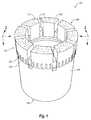
- FIG. 1is a perspective view of an impregnated drill bit as disclosed herein;
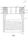
- FIG. 2is a cross-sectional view of the impregnated drill bit of FIG. 1 ;
- FIG. 3is a cross-sectional view of an impregnated drill bit comprising a plurality of large abrasive cutting elements and a plurality of small abrasive cutting elements as disclosed herein;
- FIG. 4is a cross-sectional view of an impregnated drill bit comprising a plurality of large abrasive cutting elements, a plurality of small abrasive cutting elements, and a plurality of fibers as disclosed herein;
- FIG. 5is a cross-sectional view of an impregnated drill bit comprising a first portion having a plurality of large abrasive cutting elements and a second portion having a plurality of small abrasive cutting elements as disclosed herein;
- FIG. 6is a schematic view of a drilling system comprising an impregnated drill bit as disclosed herein;
- FIG. 7is an exemplary surface-set coring drill bit as disclosed herein.
- FIGS. 8A and 8Bare SEM images of the chemical bonds between a diamond and a drill bit matrix comprising an exemplary carbide-forming alloy and a binder as disclosed herein.
- FIG. 8Cis an SEM image of a conventional coated diamond. As shown in FIG. 8C , there is a small gap between the matrix and the diamond such that the diamond is only mechanically held in place (rather than being chemically bonded in place).
- Rangescan be expressed herein as from “about” one particular value, and/or to “about” another particular value. When such a range is expressed, another aspect comprises from the one particular value and/or to the other particular value. Similarly, when values are expressed as approximations, by use of the antecedent “about,” it will be understood that the particular value forms another aspect. It will be further understood that the endpoints of each of the ranges are significant both in relation to the other endpoint, and independently of the other endpoint.
- natural diamondrefers to an industrial natural diamond that is configured for use in conventional drill bit manufacturing processes.
- the terms “optional” or “optionally”mean that the subsequently described event or circumstance can or can not occur, and that the description comprises instances where said event or circumstance occurs and instances where it does not.
- the term “longitudinal”means along the length of the drill string. Additionally, as used herein the terms “upper,” “top,” and “above” and “lower” and “below” refer to longitudinal positions on the drill string. The terms “upper,” “top,” and “above” refer to positions nearer the mast and “lower” and “below” refer to positions nearer the drilling tool (e.g., drill bit).
- the term “infiltration” or “infiltrating”involves melting a binder material and causing the molten binder to penetrate into and fill the spaces or pores of a matrix. Upon cooling, the binder can solidify, binding the particles of the matrix together.
- the term “sintering”means the removal of at least a portion of the pores between the particles (which can be accompanied by shrinkage) combined with coalescence and bonding between adjacent particles.
- drilling toolsthat comprise a shank, a crown, and a plurality of abrasive cutting elements.
- the shankcan have a first end and an opposing second end.
- the first end of the shankcan be adapted to be secured to a drill string component as further disclosed herein.
- the crowncan extend from the second end of the shank.
- the crowncan comprise: a matrix of hard particulate material and a carbide-forming alloy; a cutting face; and a crown body between the cutting face and the shank.
- the plurality of abrasive cutting elementscan be secured at least partially within the crown body.
- the carbide-forming alloyforms a direct bond with the hard particulate material of the matrix, and the carbide-forming alloy forms a direct carbide bond with at least one abrasive cutting element of the plurality of abrasive cutting elements.
- the drilling tools described hereincan be used to cut stone, subterranean mineral deposits, ceramics, asphalt, concrete, and other hard materials.
- These drilling toolscan comprise, for example, core-sampling drill bits, drag-type drill bits, reamers (including reamers with impregnated pads, reamers with broach-style pads, reamers with magnum-style pads, and reamers with premium-style pads as are known in the art), stabilizers, casing or rod shoes, and the like.
- the impregnated drilling toolcan have a shank, a crown, and a plurality of abrasive cutting elements.
- the plurality of abrasive cutting elementscan comprise relatively large cutting elements and/or small cutting elements as further disclosed herein.
- the abrasive cutting elementscan be dispersed in an unorganized arrangement throughout at least a portion of the crown.
- the plurality of abrasive cutting elementscan be dispersed in an unorganized arrangement throughout at least a portion of the crown.
- the impregnated drilling toolscan comprise relatively large abrasive cutting elements.
- these relatively large abrasive cutting elementscan allow the drilling tool to quickly remove the material of a formation being drilled due to the large depth of cut per revolution associated with the large abrasive cutting elements.
- the disclosed drilling toolscan provide increased longevity by providing additional, sub-surface large abrasive cutting elements that are exposed as the crown of the drill bit wears during drilling. Accordingly, the presence of the relatively large abrasive cutting elements can increase the cutting speed of the drilling tool as well as its durability and longevity.
- the Figures and the following textillustrate examples of impregnated, core-sampling drill bits, and methods of forming and using such drill bits.
- the disclosed systems, methods, and apparatuscan be used with other impregnated drilling and cutting tools, such as those mentioned hereinabove (e.g., reamers, stabilizers, casings, rod shoes, etc.).
- the drilling toolcan comprise a full-face drill bit.
- the drilling toolcan comprise an all-cast drill bit.
- FIGS. 1 and 2illustrate a perspective view and a cross-sectional view, respectively, of an impregnated drill bit 100 . More particularly, FIGS. 1 and 2 illustrate an impregnated, core-sampling drill bit 100 with a plurality of abrasive cutting elements 110 , which abrade and cut the material being drilled. As shown in FIG. 1 , the drill bit 100 can comprise a cutting portion or crown 102 .
- a backing layer 103can secure or connect the crown 102 to a shank or blank 104 .
- the plurality of abrasive cutting elements 110 of the crown 102can be dispersed within a matrix 114 .
- the backing layer 103which connects the crown 102 to the shank 104 , can be devoid of abrasive cutting elements.
- the backing layer 103can comprise abrasive cutting elements.
- the backing layer 103can comprise pins 105 .
- the pins 105can be formed from polycrystalline diamonds, tungsten carbide, or other materials with similar material characteristics. The pins 105 can help maintain the bit gauge and help stabilize the impregnated drill bit 100 . In alternative implementations, the backing layer 103 does not comprise pins 105 .
- the shank 104can be configured to connect the impregnated drill bit 100 to a component of a drill string.
- the upper end of the shank 104i.e., the end opposite the end secured to the backing layer 103
- the connector 106can comprise a threaded portion having one or more threads.
- FIGS. 1 and 2also illustrate that the drill bit 100 can define an interior space about its central axis for receiving a core sample.
- both the crown 102 and the shank 104can have a generally annular shape defined by an inner surface and outer surface. Accordingly, pieces of the material being drilled can pass through the interior space of the impregnated drill bit 100 and, optionally, up through an attached drill string.
- the impregnated drill bit 100can be any size, and therefore, can be used to collect core samples of any size. While the impregnated drill bit 100 can have any diameter and can be used to remove and collect core samples with any desired diameter, the diameter of the impregnated drill bit 100 can range in some implementations from about 1 inch to about 12 inches.
- the kerf of the impregnated drill bit 100can be any width, it is contemplated that the kerf can optionally range from about 1 ⁇ 4 inch to about 6 inches.
- the crown 102can be configured to cut or drill the desired materials during the drilling process.
- the crown 102can comprise a cutting face 108 and a crown body extending between the backing layer 103 or shank 104 and the cutting face 108 .
- the crown 102 of the impregnated drill bit 100can comprise a plurality of cutting segments 109 .
- the cutting segments 109can be separated by waterways 112 .
- the waterways 112can allow drilling fluid or other lubricants to flow across the cutting face 108 to help provide cooling during drilling.
- the waterways 112can also allow drilling fluid to flush cuttings and debris from the inner surface to the outer surface of the impregnated drill bit 100 .
- the crown 104can have any number of waterways 112 that provides the desired amount of fluid/debris flow and also allows the crown 102 to maintain the structural integrity needed for drilling operations.
- FIGS. 1 and 2illustrate that the impregnated drill bit 100 can comprise eight waterways 112 .
- the impregnated drill bit 100can comprise as few as one waterway or as many as 20 or more waterways, depending on the desired configuration and the formation to be drilled.
- the waterways 112can be evenly or unevenly spaced around the circumference of the crown 102 .
- FIG. 1depicts eight waterways 112 substantially evenly spaced from each other about the circumference of the crown 102 . In alternative implementations, however, the waterways 112 can be staggered or otherwise not evenly spaced.
- the plurality of abrasive cutting elements of the crown 102can comprise a plurality of relatively large abrasive cutting elements, which can allow the impregnated drill bit 100 to quickly cut soft formation material by removing more material per revolution.
- the term “relatively large”refers to abrasive cutting elements having (i) at least one dimension between about 1.0 millimeter and about 8 millimeters, or more preferably between about 2.5 millimeters and about 5 millimeters, or (ii) having a volume of between about 1 millimeter 3 and about 512 millimeters 3 , or more preferably between about 15.2 millimeters 3 and about 125 millimeters 3 , or (iii) a size between about 5 stones per carat and about 108 stones per carat.
- the “at least one dimension” of the relatively large abrasive cutting elementscan comprise a length, a diameter, a width, a height, or other dimension.
- the abrasive cutting elements 110 of the drill bit 100can have varied shapes or combinations thereof, such as, for example, spheres, cubes, cylinders, irregular shapes, or other shapes.
- the abrasive cutting elements 110can include one or more of natural diamond, synthetic diamond, polycrystalline diamond, thermally stable diamond, aluminum oxide, silicon carbide, silicon nitride, tungsten carbide, cubic boron nitride, boron carbide, alumina, seeded or unseeded sol-gel alumina, other suitable materials, or combinations thereof.
- the abrasive cutting elements 110can comprise homogenous polycrystalline diamond materials, such as thermally stable diamonds that do not have a carbide backing.
- FIG. 2illustrates that the abrasive cutting elements 110 can be dispersed at the cutting face 108 of the crown 102 .
- FIG. 2shows that the abrasive cutting elements 110 can be dispersed throughout at least a portion of the crown body (i.e., the portion of the crown 102 between the cutting face 108 and the backing layer 103 or shank 104 ).
- the abrasive cutting elements 110can be embedded within the crown 102 at the cutting face 108 , as well as behind the cutting face 108 .
- the embedded abrasive cutting elements 110are exposed to replenish the cutting face 108 .
- Such a configurationcan provide versatility in cutting as abrasive cutting elements 110 continue to be available to cut throughout the life of the impregnated drill bit 100 .
- the abrasive cutting elements 110can be dispersed throughout at least a portion of the crown 102 .
- FIG. 2illustrates that the abrasive cutting elements 110 can be dispersed substantially entirely throughout the crown 102 .
- the abrasive cutting elements 110can be dispersed throughout only a portion of the crown 102 .
- the abrasive cutting elements 110can be dispersed only in the portions of the crown 102 proximate the cutting face 108 .
- the abrasive cutting elements 110can be dispersed only in portions of the crown 102 behind the cutting face 108 .
- the abrasive cutting elements 110can be arranged in the crown 102 in an unorganized arrangement.
- the abrasive cutting elements 110can be randomly dispersed within the crown 102 .
- the abrasive cutting elements 110are not arranged in specific alignments relative to each other or the cutting face 108 .
- the abrasive cutting elements 110can be aligned in a particular manner so that the cutting properties of the cutting elements are presented in an advantageous position with respect to the cutting face 108 .
- the abrasive cutting elements 110can be dispersed substantially homogeneously throughout the crown 102 .
- the abrasive cutting elements 110can be dispersed heterogeneously throughout the crown 102 .
- the concentration of abrasive cutting elements 110can vary throughout any portion of the crown 102 , as desired.
- the crown 102can comprise a gradient of abrasive cutting elements 110 .
- the portion of the crown 102 that is closest to the cutting face 108 of the impregnated drill bit 100can contain a first concentration of abrasive cutting elements 110 , and the concentration of abrasive cutting elements 110 can gradually decrease or increase towards the backing layer 103 .
- Such an impregnated drill bit 100can be used to drill a formation that begins with a soft, abrasive, unconsolidated formation, which gradually shifts to a hard, non-consolidated formation.
- the dispersal of the abrasive cutting elements 110 in the impregnated drill bit 100can be customized to the desired formation through which it will be used to drill.
- the abrasive cutting elementscan be dispersed within a matrix 114 .
- the matrix 114can comprise a hard particulate material, such as, for example, a metal or ceramic.
- the hard particulate materialcan comprise a powdered material, such as, for example, a powdered metal or alloy, as well as ceramic compounds.
- the hard particulate materialcan comprise tungsten carbide.
- tungsten carbidemeans any material composition that contains chemical compounds of tungsten and carbon, such as, for example, WC, W 2 C, and combinations of WC and W 2 C.
- tungsten carbidecomprises, for example, cast tungsten carbide, sintered tungsten carbide, and macrocrystalline tungsten.
- the hard particulate materialcan comprise carbide, tungsten, iron, cobalt, and/or molybdenum and carbides, borides, alloys thereof, or any other suitable material.
- the matrix 114can comprise a carbide-forming alloy that is configured to form a direct carbide bond with at least one abrasive cutting element of the plurality of abrasive cutting elements.
- the carbide-forming alloycan be configured to form a direct carbide bond with a binder and/or the hard particulate matter of a matrix as further disclosed herein.
- the carbide-forming alloys disclosed hereinwill form a bonds with both the infiltrant (binder) and at least a portion of the cutting elements.
- the plurality of abrasive cutting elementscan comprise at least one cutting element that is configured to form a carbide bond with the carbide-forming alloy.
- Exemplary cutting elements that are capable of forming a carbide bond with the carbide-forming alloyinclude natural diamond, synthetic diamond, polycrystalline diamond, thermally stable diamond, and the like.
- the plurality of abrasive cutting mediacan further comprise at least one abrasive cutting element that is not configured to form a carbide bond with the carbide-forming alloy. Thus, it is not required that every cutting element within the drilling tool form a carbide bond with a carbide-forming alloy.
- the formation of a bond with both the infiltrant and the cutting elementscan create a supporting structure that retains the cutting elements (e.g., synthetic diamond cutting elements) for significantly longer than conventional matrices, such as the matrix depicted in FIG. 8C .
- the cutting elementscan be both chemically and mechanically bonded in place (in contrast to conventional bits, in which cutting elements are merely retained mechanically). The longer each cutting element is retained, the more exposure it will have, and increased exposure can allow for a larger gap between the matrix and the surface of the formation (e.g., rock) being drilled.
- the cutting elementse.g., synthetic diamonds
- the cutting elementscan undergo advantageous micro-fracturing, which creates many sharp edges instead of a “wear flat” configuration, thereby increasing the cutting efficiency of the drill bit.
- the carbide-forming alloywhich can optionally be provided as carbide-forming alloy powder or as carbide-forming alloy fibers, has a high energy potential to form a carbide with the carbon from the cutting elements (e.g., diamond).
- the carbide-forming alloycan be configured to convert the carbon from the cutting elements to form a carbide.
- an intermediate layer of the alloycan form between the carbide and the binder and the hard particulate material of the matrix (e.g., tungsten powder), thereby bonding them all together.
- the carbide-forming alloyis configured to form a carbide bond with the cutting elements (e.g., diamond) and to also form an intermediate metallic layer that bonds to the binder and the hard particulate material of the matrix (e.g., tungsten).
- the plurality of abrasive cutting elementscan comprise a plurality of diamond cutting elements, and the carbide-forming alloy can be configured to convert the diamond cutting elements to a carbide to form the direct carbide bonds between the carbide-forming alloy and the diamond cutting elements.
- the process of forming the disclosed drilling toolscan bypass or eliminate the initial coating steps of conventional PVD and CVD processes and instead create a chemically bonded coating in a heating/furnacing operation by utilizing matrix powders and binders that will react with the surface of the cutting elements to chemically form a carbide coating.
- the matrix powderscan contain the carbide-forming alloy(s), and the binder can diffuse the carbide-forming alloy(s) throughout the cutting body, thereby improving the reaction of the surface of the cutting elements to form the carbide coating.
- the disclosed process of forming a direct carbide bondcan prevent and/or limit the formation of oxides, which, in conventional drilling tools, can significantly weaken chemical bonds.
- the disclosed methodscan provide for drilling tools having stronger bonds than conventional drilling tools. More particularly, because the formation of the direct carbide bond between carbide-forming alloy and the cutting elements occurs during in situ heating of the cutting tool (within a furnace) and without the need for multiple heating operations, the disclosed drilling tools are not subject to formation of oxide layers that limit chemical bonding between the matrix powders, binders, and cutting elements.
- the drilling toolcan be infiltrated with a binder that does not comprise a carbide-forming material. Rather, the carbide-forming materials are provided in the matrix.
- the abrasive cutting elementscan be un-coated, and the carbide-forming alloy of the matrix can form direct carbide bonds with the uncoated abrasive cutting elements.
- the disclosed bindersare not needed to form the direct carbide bond between the carbide-forming alloy and the cutting elements.
- the carbide-forming alloycan optionally comprise chromium. In other exemplary aspects, the carbide-forming alloy can optionally comprise titanium. In additional exemplary aspects, the carbide-forming alloy can optionally comprise aluminum. In further exemplary aspects, the carbide-forming alloy can optionally comprise tantalum. In still further exemplary aspects, the carbide-forming alloy can optionally comprise vanadium. In still further exemplary aspects, the carbide-forming alloy can optionally comprise zirconium. However, it is contemplated that the carbide-forming alloy can optionally comprise other materials, such as, for example and without limitation, silicon, niobium, molybdenum, boron, manganese, tungsten, iron, cobalt, and nickel.
- the carbide-forming alloycan consist of a single material, such as, for example and without limitation, titanium, aluminum, tantalum, vanadium, or zirconium. It is understood that the carbide-forming alloys disclosed herein are typically provided as fine powders that can create a risk of an explosion in oxygen (O 2 ) rich environments. Thus, conventionally, manufacturers of drilling tools do not use carbide-forming alloys in the manufacturing process.
- the carbide-forming alloyscan be provided in the form of a PVD (physical vapor deposition) coating on the large abrasive cutting element (e.g., synthetic diamond).
- the large abrasive cutting elemente.g., synthetic diamond.
- additional safety precautionsmay be required to prevent exposure to “free” chromium (or other materials) that would be protected from the atmosphere if provided as a carbide-forming alloy powder as disclosed above.
- the crown 102can also comprise a binder.
- the bindercan comprise copper, zinc, silver, molybdenum, nickel, cobalt, or mixtures and alloys thereof.
- the bindercan bond to the matrix 114 and the abrasive cutting elements 110 , thereby binding the crown 102 together.
- the plurality of abrasive cutting elements 110 within the impregnated drill bit 100can comprise relatively large abrasive cutting elements.
- the drill bit 100can further comprise a plurality of small abrasive cutting elements.
- FIG. 3illustrates a cross-sectional view of an impregnated drill bit 100 a that comprises a plurality of small abrasive cutting elements 116 in addition to relatively large abrasive cutting elements 110 .
- the small abrasive cutting elementscan help the drill bit cut in harder formations where the relatively large abrasive cutting elements cannot cut, thereby preventing the bit from polishing.
- FIG. 3shows that the small abrasive cutting elements 116 can be dispersed within a matrix 114 along with the relatively large abrasive cutting elements 110 .
- the small abrasive cutting elements 116can cut a formation using abrasion.
- the small abrasive cutting elements 116can allow the impregnated drill bit 100 a to efficiently cut through harder formations.
- the term “small”refers to abrasive cutting elements having (i) a largest dimension less than about 2 millimeters, or more preferably between about 0.01 millimeters and about 1.0 millimeters, or (ii) having a volume that is less than about 0.75 times the volume of a relatively large abrasive cutting element, or more preferably less than about 0.50 times the volume of a relatively large abrasive cutting media, or (iii) a volume between about 0.001 mm 3 and about 8 mm 3 .
- the small abrasive cutting elements 116can have varied shapes or combinations thereof, such as, for example, spheres, cubes, cylinders, irregular shapes, or other shapes.
- the “largest dimension” of the small abrasive cutting elements 116can thus comprise a length, a diameter, a width, a height, or other dimension.
- the small abrasive cutting elements 116can comprise one or more of natural diamond, synthetic diamond, polycrystalline diamond, thermally stable diamond, aluminum oxide, silicon carbide, silicon nitride, tungsten carbide, cubic boron nitride, boron carbide, alumina, seeded or unseeded sol-gel alumina, other suitable materials, or combinations thereof.
- the small abrasive cutting elements 116can comprise single diamond crystals.
- FIG. 3illustrates that the small abrasive cutting elements 116 can be dispersed at the cutting face 108 of the crown 102 .
- FIG. 3shows that the small abrasive cutting elements 116 can be dispersed throughout at least a portion of the crown body (i.e., the portion of the crown 102 between the cutting face 108 and the shank 104 ).
- the small abrasive cutting elements 116can be embedded within the crown 102 at the cutting face 108 , as well as behind the cutting face 108 .
- the embedded relatively large abrasive cutting elements 110 and the small abrasive cutting elements 116can be exposed to replenish the cutting face 108 .
- Such a configurationcan provide versatility in cutting as relatively large abrasive cutting elements 110 and small abrasive cutting elements 116 continue to be available to cut throughout the life of the impregnated drill bit 100 a.
- the small abrasive cutting elements 116can be dispersed throughout at least a portion of the crown 102 .
- FIG. 3illustrates that the small abrasive cutting elements 116 can be dispersed substantially entirely throughout the crown 102 .
- the small abrasive cutting elements 116can be dispersed throughout only a portion of the crown 102 .
- the small abrasive cutting elements 116can be dispersed only in the portions of the crown 102 proximate the cutting face 108 .
- the small abrasive cutting elements 116can be dispersed only in portions of the crown 102 behind the cutting face 108 .
- the small abrasive cutting elements 116can be arranged in the crown 102 in an unorganized arrangement. In additional implementations, the small abrasive cutting elements 116 can be randomly dispersed within the crown 102 . Thus, in exemplary aspects, the small abrasive cutting elements 116 are not arranged in specific alignments relative to each other or the cutting face 108 .
- the small abrasive cutting elements 116can be dispersed homogeneously throughout the crown 102 .
- the small abrasive cutting elements 116can be dispersed heterogeneously throughout the crown 102 .
- the concentration of the small abrasive cutting elements 116can vary throughout any desired portion of the crown 102 , as desired.
- the crown 102can comprise a gradient of small abrasive cutting elements 116 .
- the portion of the crown 102 that is closest to the cutting face 108 of the impregnated drill bit 100 acan contain a first concentration of small abrasive cutting elements 116 and the concentration of small abrasive cutting elements 116 can gradually decrease or increase towards the shank 104 .
- Such an impregnated drill bit 100 acan be used to drill a formation that begins with a soft, abrasive, unconsolidated formation, which gradually shifts to a hard, non-consolidated formation.
- the dispersal of the relatively large abrasive cutting elements 110 and the small abrasive cutting elements 116 in the impregnated drill bit 100 acan be customized to the desired formation through which it will be drilling.
- the abrasive cutting elements 110 , 110 a at the cutting face 108can extend out of the cutting face 108 .
- the abrasive cutting elements 110 , 110 acan extend from the crown 102 axially away from the cutting face 108 .
- the abrasive cutting elements 110 , 110 a that extend from the crown 102can help allow for a quick start-up of a new drilling tool 100 , 100 a .
- the cutting face 108does not comprise abrasive cutting elements 110 , 110 a that extend out of the cutting face 108 , such as the impregnated drill bit 100 of FIGS. 1 and 2 .
- the cutting face 108can comprise other features for aiding in the drilling process, such as for example radial grooves.
- FIG. 4illustrates another exemplary impregnated drill bit comprising abrasive cutting elements 110 .
- FIG. 4illustrates an impregnated drill bit 100 b that comprises a crown 102 having relatively large abrasive cutting elements 110 , small abrasive cutting elements 116 , and a plurality of fibers 118 dispersed within a matrix 114 of hard particulate material.
- the crown 102 of one or more implementations of the present inventioncan comprise fibers, such as the fibers described in U.S. patent application Ser. No. 11/948,185, filed Nov. 30, 2007, entitled “Fiber-Containing Diamond Impregnated Cutting Tools,” now U.S. Pat. No.
- the fibers 118can help control the rate at which the matrix 118 erodes, and thus, the rate at which the abrasive cutting elements (comprising abrasive cutting elements 110 , which can optionally be relatively large abrasive cutting elements, and, optionally, small abrasive cutting elements 116 ) is exposed.
- the fibers 118can have varied shapes or combinations thereof, such as, for example, ribbon-like, cylindrical, polygonal, elliptical, straight, curved, curly, coiled, bent at angles, etc.
- the fibers 118 in the crown 102 of the impregnated drill bit 100 bcan be of any size or combination of sizes, comprising mixtures of different sizes.
- the fibers 118can be of any length and have any desired diameter.
- the fibers 118can be between about 10 microns and about 25,000 microns in length and can have a diameter of between about 1 micron and about 500 microns.
- the fibers 118can be about 150 microns in length and can have a diameter of about 7 microns.
- the fibers 118can comprise one or more of carbon fibers, metal fibers (e.g., fibers made of tungsten, tungsten carbide, iron, molybdenum, cobalt, or combinations thereof), glass fibers, polymeric fibers (e.g., fibers made of Kevlar), ceramic fibers (e.g., fibers made of silicon carbide), coated fibers, and/or the like.
- metal fiberse.g., fibers made of tungsten, tungsten carbide, iron, molybdenum, cobalt, or combinations thereof
- glass fiberse.g., glass fibers, polymeric fibers (e.g., fibers made of Kevlar), ceramic fibers (e.g., fibers made of silicon carbide), coated fibers, and/or the like.
- polymeric fiberse.g., fibers made of Kevlar
- ceramic fiberse.g., fibers made of silicon carbide
- FIG. 4illustrates that the fibers 118 can be dispersed at the cutting face 108 of the crown 102 .
- FIG. 4shows that the fibers 118 can be dispersed throughout at least a portion of the crown body (i.e., the portion of the crown 102 between the cutting face 108 and the shank 104 ).
- the fibers 118can be embedded within the crown 102 at the cutting face 108 , as well as behind the cutting face 108 .
- the fibers 118can be dispersed throughout at least a portion of the crown 102 .
- FIG. 4illustrates that the fibers 118 are dispersed substantially entirely throughout the crown 102 .
- the fibers 118can be dispersed throughout only a portion of the crown 102 .
- the fibers 118can be dispersed only in the portions of the crown 102 proximate the cutting face 108 .
- the fibers 118can be dispersed only in portions of the crown 102 behind the cutting face 108 .
- the fibers 118can be arranged in the crown 102 in an unorganized arrangement. In additional aspects, the fibers 118 can be randomly dispersed within the crown 102 . Thus, in exemplary aspects, the fibers 118 are not arranged in specific alignments relative to each other or the cutting face 108 .
- the fibers 118can be dispersed homogeneously throughout the crown 102 .
- the fibers 118can be dispersed heterogeneously throughout the crown 102 .
- the concentration of the fibers 118can vary throughout any portion of the crown 102 , as desired.
- the crown 102can comprise a gradient of fibers 118 .
- the portion of the crown 102 that is closest to the cutting face 108 of the impregnated drill bit 100 bcan contain a first concentration of fibers 118 and the concentration of fibers 118 can gradually decrease or increase towards the shank 104 .
- the dispersal of the abrasive cutting elements 110can be customized to the desired formation through which it will be drilling.
- FIG. 5illustrates a cross-sectional view of an impregnated drill bit 100 c with a crown 102 customized for a particular formation.
- the portion of the crown 102 a that is closest to the cutting face 108 of the impregnated drill bit 100 ccontains a plurality of abrasive cutting elements 110 , which can optionally be a plurality of relatively large abrasive cutting media.
- the portion of the crown 102 b that is closest to the shank 104 of the impregnated drill bit 100 ccan contain a plurality of small abrasive cutting elements 116 .
- Such an impregnated drill bit 100 ccan be used to drill a formation that begins with a soft, abrasive, unconsolidated formation, which gradually shifts to a hard, non-consolidated formation.
- the abrasive cutting elements 110 of the first portion of the crown 102 acan cut the soft material of the formation allowing the impregnated drill bit 100 c to penetrate the soft formation relatively quickly. Then the small abrasive cutting elements 116 of the second portion of the crown 102 b can abrade the harder material of the formation allowing the impregnated drill bit 100 c to penetrate the harder formation relatively quickly.
- the first portion of the crown 102 acan comprise small abrasive cutting elements 116
- the second portion of the crown 102 bcomprises other abrasive cutting elements 110 , which can optionally be relatively large abrasive cutting media.
- one of the first portion 102 a and the second portion 102 b of the crowncan comprise both relatively large abrasive cutting elements 110 and small abrasive cutting elements 116 .
- the impregnated drill bit 100 ccan comprise more than two distinct sections 102 a , 102 b .
- the impregnated drill bit 100 ccan comprise three, four, five or more sections each tailored to cut efficiently through different types of formations.
- FIG. 6illustrate or describe one such drilling system with which the disclosed drilling tools can be used.
- FIG. 6illustrates or describe one such drilling system with which the disclosed drilling tools can be used.
- the drilling system shown and described in FIG. 6is only one example of a system with which the disclosed drilling tools can be used.
- FIG. 6illustrates a drilling system 120 that comprises a drill head 122 .
- the drill head 122can be coupled to a mast 124 that in turn is coupled to a drill rig 126 .
- the drill head 122can be configured to have one or more tubular members 128 coupled thereto.
- Tubular memberscan comprise, without limitation, drill rods, casings, reaming shells, and down-the-hole hammers.
- the tubular members 128will be described hereinafter as drill string components.
- the drill string component 128can in turn be coupled to additional drill string components 128 to form a drill or tool string 130 .
- the drill string 130can be coupled to an impregnated drill bit 100 as disclosed herein, such as the core-sampling drill bits 100 , 100 a , 100 b , 100 c as described hereinabove.
- the impregnated drill bit 100can be configured to interface with the material 132 , or formation, to be drilled.
- the drill head 122 illustrated in FIG. 6can be configured to rotate the drill string 130 during a drilling process.
- the drill head 122can vary the speed at which the drill string 130 rotates. For instance, the rotational rate of the drill head and/or the torque the drill head 122 transmits to the drill string 130 can be selected as desired according to the drilling process.
- a down-hole motorcan be used in place of or in addition to the drill head 122 .
- the down-hole motorcan be coupled to the mast 124 and can have a drill string 130 (one or more drill string components 128 ) coupled thereto.
- the down-hole motorcan be configured to rotate the drill string 130 during a drilling process.
- the down-hole motorcan vary the speed at which the drill string 130 rotates. For instance, the rotational rate of the down-hole motor and/or the torque the down-hole motor transmits to the drill string 130 can be selected as desired according to the drilling process.
- the drilling system 120can be configured to apply a generally axial (optionally, downward) force to the drill string 130 to urge the impregnated drill bit 100 into the formation 132 during a drilling operation.
- the drilling system 120can comprise a chain-drive assembly that is configured to move a sled assembly relative to the mast 124 to apply the generally axial force to the impregnated drill bit 100 as described above.
- an impregnated drill bit 100 , 100 a , 100 b , 100 ccan be attached to the end of the drill string 130 , which is in turn connected to a drilling machine or rig 126 .
- the drill bit 100can grind away the materials in the subterranean formations 132 that are being drilled.
- the core samples that are drilled awaycan be withdrawn from the drill string 130 .
- the cutting portion of the drill bit 100can erode over time because of the grinding action. This process can continue until the cutting portion of a drill bit 100 has been consumed and the drilling string 130 can then be tripped out of the borehole and the drill bit 100 is replaced.
- the abrasive cutting elementscan be positioned within the impregnated drill bit 100 to promote formation of “comet tails” behind the abrasive cutting elements during rotation of the bit. It is contemplated that such “comet tails” can be formed by the friction and cuttings produced by contact between the bit and the formation being cut. It is contemplated that the “comet tails” can be configured to support the cutting elements and to maximize clearance between the cutting face of the crown and the formation in three dimensions. It is further contemplated that these clearances can reduce friction and heat while creating more space to efficiently flush cuttings, thereby increasing cooling of the cutting face. In combination, these features can improve overall bit performance and increase bit life.
- the comet tailscan be formed on the first layer of cutting elements (closest to the bit face) of the drill bit 100 .
- the first layer of cutting elementswears down and falls out of the drill bit, the underlying layers of cutting elements are randomly positioned, and the formation of tails cannot be controlled.
- Implementations of the present inventionalso comprise methods of forming impregnated drilling tools, such as impregnated drill bits.
- the followingdescribes at least one method of forming impregnated drilling tools having abrasive cutting elements.
- an impregnated drill bit with relatively large abrasive cutting elementscan be produced.
- the impregnated drill bitcan be formed using a conventional casting process, such as, for example, a conventional casting process for producing an all-cast bit.
- a method of forming an impregnated drill bitcan comprise preparing a matrix.
- the step of preparing a matrixcan comprise preparing a matrix of hard particulate material.
- the step of preparing a matrixcan comprise preparing a matrix of a powdered material, such as for example tungsten carbide.
- the matrixcan comprise one or more of the previously described hard particulate materials.
- the step of preparing a matrixcan comprise placing the matrix in a mold.
- the matrixcan further comprise at least one carbide-forming alloy.
- the moldcan be formed from a material that is capable of withstanding the heat to which the matrix will be subjected during a heating process.
- the moldcan be formed from carbon. It is contemplated that the mold can be shaped to form a drilling tool (such as a drill bit) having desired features. In exemplary aspects, the mold can correspond to a core drill bit.
- the methodcan comprise dispersing a plurality of abrasive cutting elements throughout at least a portion of the matrix. Additionally, the method can comprise dispersing the abrasive cutting elements randomly or in an unorganized arrangement throughout the matrix.
- the step of dispersing a plurality of abrasive cutting elementscan optionally comprise dispersing a plurality of relatively large abrasive cutting elements and/or a plurality of small abrasive cutting elements throughout at least a portion of the matrix. Additionally, the method can comprise dispersing the relatively large and/or small abrasive cutting elements randomly or in an unorganized arrangement throughout the matrix.
- the methodcan further comprise dispersing a plurality of fibers throughout at least a portion of the matrix.
- the methodcan comprise dispersing carbon fibers randomly or in an unorganized arrangement throughout the matrix.
- the methodcan comprise infiltrating the matrix with a binder.
- the step of infiltrating the matrix with a bindercan comprise heating the binder to a molten state and infiltrating the matrix with the molten binder.
- the bindercan be placed proximate the matrix 114 and the matrix 114 and the binder can be heated to a temperature sufficient to bring the binder to a molten state.
- the molten bindercan infiltrate the matrix 114 .
- the step of infiltrating the matrix with a bindercan comprise heating the matrix 114 and the binder to a temperature of at least 787° F.
- the binderin powder form
- one or more conventional fluxing agentscan be positioned on top of the binder.
- the one or more fluxing agentscan be configured to prevent formation of, or remove, oxides.
- fluxing agentsinclude borates, fused borax, fluoborates, elemental boron, fluorides, chlorides, boric acid, alkalies, wetting agents, water, conventional solvents (e.g., alcohols), and combinations thereof. It is contemplated that the use of such fluxing agents can improve bonding among the hard particulate material, carbide-forming alloys, binder, and cutting elements of the drilling tool and reduce surface tension and promote the free flow of the binder during the infiltration process.
- the carbide-forming alloy of the matrixcan form a direct bond with the binder and the hard particulate material of the matrix and form a direct carbide bond with the plurality of abrasive cutting elements (e.g., synthetic diamond) of the matrix. It is further contemplated that the carbide-forming alloy has a high energy potential to form a carbide bond with the carbon from the abrasive cutting elements (e.g., synthetic diamond). In other words, the carbide-forming alloy can be configured to convert the carbon from the cutting elements to form a carbide.
- the carbon from the abrasive cutting elementscan be provided with an excess amount of the carbide-forming alloy, which in turn can form an intermediate layer of the alloy between the carbide and the binder, thereby bonding them all (the carbide-forming alloy, the carbide, and the binder) together.
- the carbide-forming alloycan form a carbide with the abrasive cutting elements and can also form an intermediate metallic layer that bonds to the binder and the hard particulate material of the matrix (e.g., tungsten).
- the disclosed process of forming a direct carbide bondcan prevent and/or limit the formation of oxides, which, in conventional drilling tools, can significantly weaken, or not allow, chemical bonds.
- the disclosed methodscan provide for drilling tools having stronger bonds than conventional drilling tools. More particularly, because the formation of the direct carbide bond between carbide-forming alloy and the cutting elements occurs during in situ heating of the cutting tool (within a furnace) and without the need for multiple heating operations, the disclosed drilling tools are not subject to formation of oxide layers that limit chemical bonding between the matrix powders, binders, and cutting elements.
- the drilling toolcan be infiltrated with a binder that does not comprise a carbide-forming material.
- the abrasive cutting elementscan be un-coated, and the carbide-forming alloy of the matrix can form direct carbide bonds with the uncoated abrasive cutting elements. That is, the abrasive cutting elements are initially un-coated, and the carbide-forming alloy and binder cooperate to coat the abrasive cutting elements in situ within a furnace.
- the disclosed bindersare not needed to form the direct carbide bond between the carbide-forming alloy and the cutting elements. It is contemplated that any coating of the abrasive cutting elements would interfere with the required direct carbide bonding between the abrasive cutting elements and the carbide-forming alloy.
- the bindercan comprise copper, zinc, silver, molybdenum, nickel, cobalt, tin, iron, aluminum, silicon, manganese, or mixtures and alloys thereof. It is contemplated that the binder can cool, thereby bonding to portions of the matrix and abrasive cutting elements, and thereby binding portions of the matrix and abrasive cutting media together. In some aspects, the time and/or temperature of the infiltration process can be increased to allow the binder to fill-up a greater number and greater amount of the pores of the matrix. It is contemplated that this can both reduce the shrinkage during sintering, and increase the strength of the resulting drilling tool.
- the methodcan comprise securing a shank 104 to the matrix 114 .
- the step of securing a shank to the matrixcan comprise placing a shank 104 in contact with the matrix 114 .
- a backing layer 103 of additional matrix, binder material, and/or fluxe.g., one or more fluxing agents as disclosed herein
- fluxe.g., one or more fluxing agents as disclosed herein
- one or more of the disclosed methodscan comprise sintering the matrix 14 to a desired density.
- sinteringinvolves densification and removal of porosity within a structure
- the structure being sinteredcan shrink during the sintering process. It is contemplated that a structure can experience linear shrinkage of between 1% and 40% during sintering. As a result, it can be desirable to consider and account for dimensional shrinkage when designing tooling (molds, dies, etc.) or machining features in structures that are less than fully sintered.
- the schematics and methods described hereinprovide a number of unique products that can be effective for drilling through both soft and hard formations. Additionally, such products can have an increased drilling penetration rate due to the large abrasive cutting elements. Furthermore, as the abrasive cutting elements can be dispersed throughout the crown, new abrasive cutting elements can be continually exposed during the drilling life of the impregnated drill bit.
- the surface-set drilling toolcan have a shank, a crown, and a plurality of abrasive cutting elements.
- the abrasive cutting elementscan be secured at the cutting face of the drilling tool in the manner of conventional surface-set drilling tools.
- the surface-set drilling tools described hereincan be used to cut stone, subterranean mineral deposits, ceramics, asphalt, concrete, and other soft or hard materials.
- the Figures and the following textillustrate examples of surface-set, core-sampling drill bits, and methods of forming and using such drill bits.
- the disclosed systems, methods, and apparatuscan be used with other surface-set drilling and cutting tools, such as, for example and without limitation, a surface-set reamer or a hybrid surface-set/impregnated reamer.
- the disclosed surface-set bitscan be full-face surface-set bits.
- the disclosed surface-set bitscan be all-cast surface-set bits.
- the abrasive cutting elements at the cutting facecan allow the surface-set drill bits to cut effectively and efficiently through softer formations.
- the disclosed surface-set drill bitscan cut through softer formations at relatively high cutting speeds.
- the abrasive cutting elementscan comprise synthetic diamonds, which fracture and create new cutting edges during drilling operations. This is in contrast to polycrystalline diamonds, which fracture across grain boundaries.
- FIG. 7illustrates a perspective view of a surface-set drill bit 200 . More particularly, FIG. 7 illustrates a surface-set, core-sampling drill bit 200 with a plurality of abrasive cutting elements 214 secured to the cutting face of the drill bit. As shown in FIG. 7 , the drill bit 100 a can comprise a cutting portion or crown 202 .
- the drill bit 200can comprise a shank portion 204 with a first end 208 that is configured to connect the drill bit 200 to a component of a drill string.
- the first end 208can define a threaded portion configured for engagement with corresponding threads of a component of a drill string.
- the shank portion 208may be formed from steel, another iron-based alloy, or any other material that exhibits acceptable physical properties.
- the drill bit 200can have a generally annular shape defined by an inner surface 210 and an outer surface 212 .
- the drill bits 200can define an interior space about its central axis for receiving a core sample. Accordingly, pieces of the material being drilled can pass through the interior space of the drill bit 200 and up through an attached drill string.
- the drill bit 200may be any size, and therefore, may be used to collect core samples of any size. While the drill bit 200 may have any diameter and may be used to remove and collect core samples with any desired diameter, the diameter of the drill bit 200 can range in some aspects from about 1 inch to about 12 inches. Similarly, while the kerf of the surface-set drill bit 200 (i.e., the radius of the outer surface minus the radius of the inner surface) can be any width, it is contemplated that the kerf can optionally range from about 1 ⁇ 4 inch to about 6 inches.
- the annular crown 202can be formed from a hard particulate material infiltrated with a binder as is known in the art. Furthermore, the crown 202 can comprise a plurality of cutting elements 214 that are secured to and project from the cutting face of the crown.
- the cutting elementscan comprise one or more of natural diamonds, synthetic diamonds, polycrystalline diamond or thermally stable diamond products, aluminum oxide, silicon carbide, silicon nitride, tungsten carbide, cubic boron nitride, alumina, seeded or unseeded sol-gel alumina, other suitable materials, or combinations thereof.
- the cutting elementscan have varied shapes or combinations thereof, such as, for example, spherical, cubical, cylindrical, irregular shapes, or other polyhedral shapes.
- the cutting elements 214can optionally comprise a plurality of relatively large cutting elements as defined herein, such as for example and without limitation, relatively large synthetic diamonds.
- the cutting elements 214can comprise a plurality of relatively large cutting elements and a plurality of small cutting elements as defined herein.
- the disclosed surface-set bitscan have any known configuration.
- the crown 202can comprise a plurality of cutting segments that are separated by waterways.
- the waterwayscan allow drilling fluid or other lubricants to flow across the cutting face to help provide cooling during drilling.
- the waterwayscan also allow drilling fluid to flush cuttings and debris from the inner surface to the outer surface of the surface-set drill bit 200 .
- the crown 202can be formed from a matrix of hard particulate material, such as for example, a metal.
- the hard particulate materialmay comprise a powdered material, such as for example, a powdered metal or alloy, as well as ceramic compounds.
- the hard particulate materialcan comprise tungsten carbide.
- tungsten carbidemeans any material composition that contains chemical compounds of tungsten and carbon, such as, for example, WC, W 2 C, and combinations of WC and W 2 C.
- tungsten carbidecan comprise, for example, cast tungsten carbide, sintered tungsten carbide, and macrocrystalline tungsten.
- the hard particulate materialcan comprise carbide, tungsten, iron, cobalt, and/or molybdenum and carbides, borides, alloys thereof, or any other suitable material.
- the hard particulate material of the crown 202can be infiltrated with a binder, which can provide the crown with increased wear resistance, thereby increasing the life of the drill bit 200 .
- the bindercan bond to the hard particulate material and the abrasive cutting elements to form the crown 202 . It is contemplated that the binder can provide the crown 202 with increased wear resistance, while also not degrading any surface set cutting elements.
- the bindercan comprise copper, zinc, silver, molybdenum, nickel, cobalt, or mixture and alloys thereof.
- the bindercan bond to the matrix and the cutting elements, thereby binding the crown 202 together.
- the bindercan comprise a binder as disclosed in U.S. Patent Publication No. 2013/0098691, entitled “High-Strength, High-Hardness Binders and Drilling Tools Formed Using the Same,” which is incorporated herein by reference in its entirety.
- the cutting elementscan be secured at the cutting face of the crown 202 such that a portion of each cutting element projects from the cutting face.
- the cutting elementscan be partially embedded within the crown 202 at the cutting face.
- the cutting elementscan be arranged on the cutting face of the crown 202 in an unorganized arrangement.
- the cutting elementscan be randomly dispersed at the cutting face of the crown 202 .
- the cutting elementsare not arranged in specific alignments relative to each other or the cutting face.
- the cutting elementscan be aligned in a particular manner so that the cutting properties of the cutting elements are presented in an advantageous position with respect to the cutting face.
- the cutting elementscan be dispersed substantially homogeneously at the cutting face of the crown 202 .
- the cutting elementscan be dispersed heterogeneously at the cutting face of the crown 202 .
- the matrix of the crown 202can comprise a carbide-forming alloy that is configured to form a direct carbide bond with at least one abrasive cutting element of the plurality of cutting elements, such as, for example and without limitation, the relatively large cutting elements described herein.
- the carbide-forming alloycan be configured to form a direct bond with a binder and/or the hard particulate material of a matrix as disclosed herein.
- the carbide-forming alloys disclosed hereinbond to both the infiltrant (binder) and at least a portion of the cutting elements.
- the plurality of abrasive cutting elementscan comprise at least one cutting element (e.g., natural diamond, synthetic diamond, polycrystalline diamond, thermally stable diamond) that is configured to form a carbide bond with the carbide-forming alloy.
- the plurality of abrasive cutting elementscan further comprise at least one abrasive cutting element that is not configured to form a carbide bond with the carbide-forming alloy.
- every cutting element within the drilling toolform a carbide bond with a carbide-forming alloy.
- the formation of a bond with both the infiltrant and the cutting elementscan create a supporting structure that retains the cutting elements (e.g., synthetic diamond) for significantly longer than conventional matrices, such as the matrix depicted in FIG. 8C .
- the cutting elementscan be both chemically and mechanically bonded in place (in contrast to conventional bits, in which cutting elements are merely retained mechanically). The longer the diamond (or other cutting element) is retained, the more exposure it will have, and increased exposure can allow for a larger gap between the matrix and the surface of the formation (e.g., rock) being drilled.
- the cutting elementse.g., diamonds
- the cutting elementscan undergo advantageous micro-fracturing, which creates many sharp edges instead of a “wear flat” configuration, thereby increasing the cutting efficiency of the drill bit.
- the carbide-forming alloywhich can optionally be provided as carbide-forming alloy powder or as carbide-forming alloy fibers, has a high energy potential to form a carbide with the carbon from the cutting elements (e.g., diamond).
- the carbide-forming alloycan be configured to convert the carbon from the cutting elements to form a carbide.
- an intermediate layer of the alloycan form between the carbide and the binder and the hard particulate material of the matrix (e.g., tungsten powder), thereby bonding them all together.
- the carbide-forming alloyis configured to form a carbide bond with the cutting elements (e.g., diamond) and to also form an intermediate metallic layer that bonds to the binder and the hard particulate material of the matrix (e.g., tungsten) while being in the temperature/pressure range that does not significantly graphitize the cutting elements (e.g., diamond).
- the plurality of abrasive cutting elementscan comprise a plurality of diamond cutting elements, and the carbide-forming alloy can be configured to convert the diamond cutting elements to a carbide to form the direct carbide bonds between the carbide-forming alloy and the diamond cutting elements.
- the disclosed process of forming a direct carbide bondcan prevent and/or limit the formation of oxides, which, in conventional drilling tools, can significantly weaken chemical bonds.
- the disclosed methodscan provide for drilling tools having stronger bonds than conventional drilling tools. More particularly, because the formation of the direct carbide bond between carbide-forming alloy and the cutting elements occurs during in situ heating of the cutting tool (within a furnace) and without the need for multiple heating operations, the disclosed drilling tools are not subject to formation of oxide layers that limit chemical bonding between the matrix powders, binders, and cutting elements.
- the drilling toolcan be infiltrated with a binder that does not comprise a carbide-forming material. Rather, the carbide-forming materials are provided in the matrix.
- the abrasive cutting elementscan be un-coated, and the carbide-forming alloy of the matrix can form direct carbide bonds with the uncoated abrasive cutting elements.
- the disclosed bindersare not needed to form the direct carbide bond between the carbide-forming alloy and the cutting elements.
- the carbide-forming alloycan optionally comprise chromium. In other exemplary aspects, the carbide-forming alloy can optionally comprise titanium. In additional exemplary aspects, the carbide-forming alloy can optionally comprise aluminum. In further exemplary aspects, the carbide-forming alloy can optionally comprise tantalum. In still further exemplary aspects, the carbide-forming alloy can optionally comprise vanadium. In still further exemplary aspects, the carbide-forming alloy can optionally comprise zirconium. However, it is contemplated that the carbide-forming alloy can optionally comprise other materials, such as, for example and without limitation, silicon, niobium, molybdenum, boron, manganese, tungsten, iron, cobalt, and nickel.
- the carbide-forming alloycan consist of a single material, such as, for example and without limitation, titanium, aluminum, tantalum, vanadium, or zirconium. It is understood that the carbide-forming alloys disclosed herein are typically provided as fine powders that can create a risk of an explosion in oxygen (O 2 ) rich environments. Thus, conventionally, manufacturers of drilling tools do not use carbide-forming alloys in the manufacturing process.
- the carbide-forming alloyscan be provided in the form of a PVD (physical vapor deposition) coating on the diamond (or other abrasive cutting media).
- PVDphysical vapor deposition
- additional safety precautionsmay be required to prevent exposure to “free” chromium (or other materials) that would be protected from the atmosphere if provided as a carbide-forming alloy powder as disclosed above.
- FIG. 7further illustrates that, in exemplary aspects, the cutting elements at the cutting face can extend out of the cutting face.
- the cutting elements at the cutting facecan extend from the crown 202 axially away from the cutting face. The cutting elements can help allow for a quick start-up of a new drill bit 200 .
- the surface-set drilling toolse.g., surface-set drill bits
- the surface-set drilling toolscan be used with almost any type of drilling system to perform various drilling operations.
- the surface-set drilling toolscan be used with a drilling system as depicted in FIG. 6 (with the surface-set drill bit 200 being used in place of the impregnated drill bit 100 ).
- the drilling system shown and described in FIG. 6is only one example of a system with which the disclosed drilling tools can be used.
- An exemplary, non-limiting drilling systemcan comprise a drill head.
- the drill headcan be coupled to a mast that in turn is coupled to a drill rig.
- the drill headcan be configured to have one or more tubular members coupled thereto.
- Tubular memberscan comprise, without limitation, drill rods, casings, reaming shells, and down-the-hole hammers.
- the tubular memberswill be described hereinafter as drill string components.
- the drill string componentcan in turn be coupled to additional drill string components to form a drill or tool string.
- the drill stringcan be coupled to a surface-set drill bit 200 as described hereinabove. As alluded to previously, the surface-set drill bit 200 can be configured to interface with the material, or formation, to be drilled.
- the drill headcan be configured to rotate the drill string during a drilling process.
- the drill headcan vary the speed at which the drill string rotates. For instance, the rotational rate of the drill head and/or the torque the drill head transmits to the drill string can be selected as desired according to the drilling process.
- a down-hole motorcan be used in place of or in addition to the drill head.
- the down-hole motorcan be coupled to the mast and can have a drill string (one or more drill string components) coupled thereto.
- the down-hole motorcan be configured to rotate the drill string during a drilling process.
- the down-hole motorcan vary the speed at which the drill string rotates. For instance, the rotational rate of the down-hole motor and/or the torque the down-hole motor transmits to the drill string can be selected as desired according to the drilling process.
- the drilling systemcan be configured to apply a generally longitudinal downward force to the drill string to urge the surface-set drill bit 200 into the formation during a drilling operation.
- the drilling systemcan comprise a chain-drive assembly that is configured to move a sled assembly relative to the mast to apply the generally longitudinal force to the surface-set drill bit 200 .
- a surface-set drill bit 200can be attached to the end of the drill string, which is in turn connected to a drilling machine or rig. As the drill string and therefore surface-set drill bit 200 are rotated and pushed by the drilling machine, the drill bit 200 can grind away the materials in the subterranean formations that are being drilled. The core samples that are drilled away can be withdrawn from the drill string. The cutting portion of the drill bit 200 can erode over time because of the grinding action. This process can continue until the abrasive cutting elements 214 have been consumed and the drilling string can then be tripped out of the borehole and the drill bit 200 is replaced.
- the cutting elementscan be positioned at the cutting face of the surface-set bit 200 to promote formation of “comet tails” behind the cutting elements during rotation of the bit. It is contemplated that such “comet tails” can be formed by the friction and cuttings produced by contact between the bit and the formation being cut. It is contemplated that the “comet tails” can be configured to support the cutting elements and to maximize clearance between the cutting face of the crown and the formation in three dimensions. It is further contemplated that these clearances can reduce friction and heat while creating more space to efficiently flush cuttings, thereby increasing cooling of the cutting face. In combination, these features can improve overall bit performance and increase bit life.
- Implementations of the present inventionalso comprise methods of forming surface-set drilling tools, such as, for example and without limitation, surface-set drill bits as disclosed herein.
- surface-set drilling toolssuch as, for example and without limitation, surface-set drill bits as disclosed herein.
- the followingdescribes at least one method of forming surface-set drilling tools.
- the surface-set drill bitcan be formed using a conventional casting process, such as a conventional casting process for producing an all-cast surface-set drill bit.
- a method of forming a surface-set drilling toolcan comprise preparing a matrix.
- the step of preparing a matrixcan comprise preparing a matrix of hard particulate material.
- the step of preparing a matrixcan comprise preparing a matrix of a powdered material, such as for example tungsten carbide.
- the matrixcan comprise one or more of the previously described hard particulate materials.
- the step of preparing a matrixcan comprise placing the matrix in a mold.
- the matrixcan further comprise a carbide-forming alloy.
- the moldcan be formed from a material that is capable of withstanding the heat to which the matrix will be subjected during a heating process.
- the moldcan be formed from carbon. It is contemplated that the mold can be shaped to form a drilling tool (e.g., drill bit) having desired features.
- the moldcan correspond to a core drill bit.
- the step of preparing the matrixcan comprise using the mold to define a cutting face of the surface-set drill bit.
- the methodcan comprise infiltrating the matrix with a binder.
- the step of infiltrating the matrix with a bindercan comprise heating the binder to a molten state and infiltrating the matrix with the molten binder.
- the bindercan be placed proximate the matrix, and the matrix and the binder can be heated to a temperature sufficient to bring the binder to a molten state.
- the molten bindercan infiltrate the matrix.
- the step of infiltrating the matrix with a bindercan comprise heating the matrix and the binder to a temperature of at least 787° F.
- the binderin powder form
- one or more conventional fluxing agentscan be positioned on top of the binder.
- the one or more fluxing agentscan be configured to prevent formation of, or remove, oxides.
- fluxing agentsinclude borates, fused borax, fluoborates, elemental boron, fluorides, chlorides, boric acid, alkalies, wetting agents, water, conventional solvents (e.g., alcohols), and combinations thereof. It is contemplated that the use of such fluxing agents can improve bonding among the hard particulate material, carbide-forming alloys, binder, and cutting elements of the drilling tool and reduce surface tension and promote the free flow of the binder during the infiltration process.
- the methodcan comprise securing the plurality of abrasive cutting elements to the cutting face defined by the matrix. Additionally, the method can comprise dispersing the cutting elements randomly or in an unorganized arrangement at the cutting face of the matrix.
- each cutting mediumcan be set within a plot mark defined by a mold in a conventional manner.
- the steps of preparing the matrix, infiltrating the matrix, securing the plurality of abrasive cutting media, and securing the shankcan be performed using a casting process.
- the cutting elementscan be set at the cutting face (e.g., within a plot mark defined by a mold) in any desired orientation.
- the carbide-forming alloy of the matrixcan form a direct bond with the binder and the hard particulate material of the matrix and form a direct carbide bond with the plurality of abrasive cutting elements (e.g., synthetic diamond) of the matrix. It is further contemplated that the carbide-forming alloy has a high energy potential to form a carbide with the carbon from the cutting elements (e.g., diamond). In other words, the carbide-forming alloy can be configured to convert the carbon from the cutting elements to form a carbide.
- the carbon from the cutting elementscan be provided with an excess amount of the carbide-forming alloy, which in turn can form an intermediate layer of the alloy between the carbide and the binder, thereby bonding them all (the carbide-forming alloy, the carbide, and the binder) together.
- the carbide-forming alloycan form a carbide with the cutting elements (e.g., diamond) and can also form an intermediate metallic layer that bonds to the binder and the hard particulate material of the matrix (e.g., tungsten).
- the disclosed process of forming a direct carbide bondcan prevent and/or limit the formation of oxides, which, in conventional drilling tools, can significantly weaken chemical bonds.
- the disclosed methodscan provide for drilling tools having stronger bonds than conventional drilling tools. More particularly, because the formation of the direct carbide bond between carbide-forming alloy and the cutting elements occurs during in situ heating of the cutting tool (within a furnace) and without the need for multiple heating operations, the disclosed drilling tools are not subject to formation of oxide layers that limit chemical bonding between the matrix powders, binders, and cutting elements.
- the drilling toolcan be infiltrated with a binder that does not comprise a carbide-forming material.
- the abrasive cutting elementscan be un-coated, and the carbide-forming alloy can form direct carbide bonds with the uncoated abrasive cutting elements. That is, the abrasive cutting elements are initially un-coated, and the carbide-forming alloy and binder cooperate to coat the abrasive cutting elements in situ within a furnace.
- the disclosed bindersare not needed to form the direct carbide bond between the carbide-forming alloy and the cutting elements. It is contemplated that any coating of the abrasive cutting elements would interfere with the required direct carbide bonding between the abrasive cutting elements and the carbide-forming alloy.
- the bindercan comprise copper, zinc, silver, molybdenum, nickel, cobalt, tin, iron, aluminum, silicon, manganese, or mixtures and alloys thereof. It is contemplated that the binder can cool, thereby bonding to the matrix and abrasive cutting media, and thereby binding the matrix and abrasive cutting media together. In some aspects, the time and/or temperature of the infiltration process can be increased to allow the binder to fill-up a greater number and greater amount of the pores of the matrix. It is contemplated that this can both reduce the shrinkage during sintering, and increase the strength of the resulting drilling tool.
- the methodcan comprise securing a shank 204 to the matrix of the crown 202 .
- the step of securing a shank to the matrixcan comprise placing a shank 204 in contact with the matrix.
- a backing layer of additional matrix, binder material, and/or fluxe.g., one or more fluxing agents as disclosed herein
- fluxcan optionally be added and placed in contact with the matrix as well as the shank 204 to complete initial preparation of a green drill bit. Once the green drill bit has been formed, it can be placed in a furnace to thereby consolidate the drill bit. Thereafter, the drill bit can be finished through machine processes as desired.
- one or more of the disclosed methodscan comprise sintering the matrix to a desired density.
- sinteringinvolves densification and removal of porosity within a structure
- the structure being sinteredcan shrink during the sintering process. It is contemplated that a structure can experience linear shrinkage of between 1% and 40% during sintering. As a result, it can be desirable to consider and account for dimensional shrinkage when designing tooling (molds, dies, etc.) or machining features in structures that are less than fully sintered.
- a drilling toolcomprising: a shank having a first end and an opposing second end, the first end being adapted to be secured to a drill string component; a crown extending from the second end of the shank, the crown comprising a matrix of hard particulate material and a carbide-forming alloy, a cutting face, and a crown body between the cutting face and the shank; and a plurality of abrasive cutting elements secured at least partially within the crown body, wherein the carbide-forming alloy forms a direct bond with the hard particulate material of the matrix, and wherein the carbide-forming alloy forms a direct carbide bond with at least one abrasive cutting element of the plurality of abrasive cutting elements.
- Aspect 2The drilling tool as recited in aspect 1, wherein the carbide-forming alloy comprises chromium.
- Aspect 3The drilling tool as recited in aspect 1, wherein the carbide-forming alloy comprises titanium.
- Aspect 4The drilling tool as recited in aspect 1, wherein the carbide-forming alloy comprises aluminum.
- Aspect 5The drilling tool as recited in aspect 1, wherein the carbide-forming alloy comprises vanadium.
- Aspect 6The drilling tool as recited in aspect 1, wherein the plurality of abrasive cutting elements comprises a plurality of synthetic diamonds.
- Aspect 7The drilling tool as recited in aspect 1, wherein the plurality of abrasive cutting elements comprises a plurality of thermally stable polycrystalline diamonds.
- Aspect 8The drilling tool as recited in aspect 1, wherein the plurality of abrasive cutting elements comprises natural diamond.
- Aspect 9The drilling tool as recited in aspect 1, wherein the crown has an annular shape, a longitudinal axis, an inner surface, and an outer surface, wherein the inner surface of the crown defines an interior space about the longitudinal axis, and wherein the interior space is configured to receive a core sample.
- Aspect 10The drilling tool as recited in aspect 1, wherein at least one abrasive cutting element of the plurality of abrasive cutting elements extends outwardly from the cutting face.
- Aspect 11The drilling tool as recited in aspect 1, wherein the hard particulate material of the matrix of the crown comprises at least one of tungsten and tungsten carbide.
- Aspect 12The drilling tool as recited in aspect 1, wherein the drilling tool is a drill bit.
- Aspect 13The drilling tool as recited in aspect 12, wherein the drill bit is a full-face drill bit.
- Aspect 14The drilling tool as recited in aspect 12, wherein the drill bit is an all-cast drill bit.
- Aspect 15The drilling tool as recited in aspect 1, wherein the drilling tool is a reamer.
- Aspect 16The drilling tool as recited in aspect 1, wherein the drilling tool is an impregnated drilling tool, and wherein the plurality of abrasive cutting elements are dispersed throughout at least a portion of the crown body.
- Aspect 17The drilling tool as recited in aspect 16, wherein the impregnated drilling tool is an impregnated drill bit.
- Aspect 18The drilling tool as recited in aspect 16, wherein at least a portion of the plurality abrasive cutting elements are dispersed within the crown body proximate the cutting face.
- Aspect 19The drilling tool as recited in aspect 16, further comprising a plurality of fibers dispersed in an unorganized arrangement throughout at least a portion of the crown body.
- Aspect 20The drilling tool as recited in aspect 1, wherein the drilling tool is a surface-set drilling tool, and wherein the plurality of abrasive cutting elements are secured to and project from the cutting face of the crown.
- Aspect 21The drilling tool as recited in aspect 16, wherein the surface-set drilling tool is a surface-set drill bit.
- Aspect 22The drilling tool as recited in aspect 1, wherein the plurality of abrasive cutting elements comprises at least one abrasive cutting element that is not configured to form a carbide bond with the carbide-forming alloy.
- Aspect 23The drilling tool as recited in aspect 1, wherein the drilling tool is infiltrated with a binder, and wherein the binder does not comprise a carbide-forming material.
- Aspect 24The drilling tool as recited in aspect 23, wherein the abrasive cutting elements are not coated, and wherein the carbide-forming alloy forms direct carbide bonds with the uncoated abrasive cutting elements.
- Aspect 25The drilling tool as recited in aspect 1, wherein the plurality of abrasive cutting elements comprise a plurality of diamond cutting elements, and wherein the carbide-forming alloy is configured to convert the diamond cutting elements to a carbide to form the direct carbide bonds between the carbide-forming alloy and the diamond cutting elements.
- a drilling systemcomprising: a drill string configured for rotation; and a drilling tool, wherein the drilling tool comprises: a shank having a first end and an opposing second end, the first end being adapted to be secured to a drill string component; a crown extending from the second end of the shank, the crown comprising a matrix of hard particulate material and a carbide-forming alloy, a cutting face, and a crown body between the cutting face and the shank; and a plurality of abrasive cutting elements secured at least partially within the crown body, wherein the carbide-forming alloy forms a direct bond with the hard particulate material of the matrix, and wherein the carbide-forming alloy forms a direct carbide bond with at least one abrasive cutting element of the plurality of abrasive cutting elements.
- Aspect 27The drilling system as recited in aspect 26, further comprising a drill rig, wherein the drill string is adapted to be secured to and rotated by the drill rig.
- Aspect 28The drilling system as recited in aspect 26, further comprising a down-hole motor, wherein the drill string is adapted to be secured to and rotated by the down-hole motor.
- Aspect 29The drilling system as recited in aspect 26, wherein the drilling tool is infiltrated with a binder, and wherein the binder does not comprise a carbide-forming material.
- Aspect 30The drilling system as recited in aspect 29, wherein the abrasive cutting elements are not coated, and wherein the carbide-forming alloy forms direct carbide bonds with the uncoated abrasive cutting elements.
- Aspect 31The drilling system as recited in aspect 26, wherein the plurality of abrasive cutting elements comprise a plurality of diamond cutting elements, and wherein the carbide-forming alloy is configured to convert the diamond cutting elements to a carbide to form the direct carbide bonds between the carbide-forming alloy and the diamond cutting elements.
- a method of drillingcomprising: securing a drilling tool to a drill string, wherein the drilling tool comprises: a shank having a first end and an opposing second end, the first end being adapted to be secured to a drill string component; a crown extending from the second end of the shank, the crown comprising a matrix of hard particulate material and a carbide-forming alloy, a cutting face, and a crown body between the cutting face and the shank; and a plurality of abrasive cutting elements secured at least partially within the crown body, wherein the carbide-forming alloy forms a direct bond with the hard particulate material of the matrix, and wherein the carbide-forming alloy forms a direct carbide bond with at least one abrasive cutting element of the plurality of abrasive cutting elements; and rotating the drill string to cause the drilling tool to penetrate an earthen formation.
- Aspect 33The method as recited in aspect 32, further comprising securing the drill string to a drill rig and using the drill rig to rotate the drill string.
- Aspect 34The method as recited in aspect 32, further comprising securing the drill string to a down-hole motor and using the down-hole motor to rotate the drill string.
- Aspect 35The method as recited in aspect 32, wherein the drilling tool is infiltrated with a binder, and wherein the binder does not comprise a carbide-forming material.
- Aspect 36The method as recited in aspect 35, wherein the abrasive cutting elements are not coated, and wherein the carbide-forming alloy forms direct carbide bonds with the uncoated abrasive cutting elements.
- Aspect 37The method as recited in aspect 32, wherein the plurality of abrasive cutting elements comprise a plurality of diamond cutting elements, and wherein the carbide-forming alloy is configured to convert the diamond cutting elements to a carbide to form the direct carbide bonds between the carbide-forming alloy and the diamond cutting elements.
- a method of forming a drilling toolcomprising: preparing a matrix of the drilling tool, the matrix comprising hard particulate material and a carbide-forming alloy; securing a plurality of abrasive cutting elements within at least a portion of the matrix; infiltrating the matrix with a binder; and securing a shank to the matrix, wherein the carbide-forming alloy of the matrix forms a direct bond with the binder and the hard particulate material of the matrix, and wherein the carbide-forming alloy of the matrix forms a direct carbide bond with at least one abrasive cutting element of the plurality of abrasive cutting elements.
- Aspect 39The method as recited in aspect 38, wherein the drilling tool is formed using a casting process.
- Aspect 40The method as recited in aspect 38, wherein the drilling tool is an impregnated drilling tool, and wherein the plurality of abrasive cutting elements are dispersed throughout at least a portion of the matrix.
- Aspect 41The method as recited in aspect 38, wherein the drilling tool is a surface-set drilling tool, wherein the step of preparing the matrix comprises defining a cutting face of the surface-set drilling tool, and wherein the plurality of abrasive cutting elements are secured to the cutting face such that the abrasive cutting elements project from the cutting face.
- Aspect 42The method as recited in aspect 38, wherein the binder does not comprise a carbide-forming material.
- Aspect 43The method as recited in aspect 42, wherein the abrasive cutting elements are not coated, and wherein the carbide-forming alloy forms direct carbide bonds with the uncoated abrasive cutting elements.
- Aspect 44The method as recited in aspect 38, wherein the plurality of abrasive cutting elements comprise a plurality of diamond cutting elements, and wherein the carbide-forming alloy converts the diamond cutting elements to a carbide to permit formation of the direct carbide bonds between the carbide-forming alloy and the diamond cutting elements.
Landscapes
- Engineering & Computer Science (AREA)
- Chemical & Material Sciences (AREA)
- Mechanical Engineering (AREA)
- Materials Engineering (AREA)
- Organic Chemistry (AREA)
- Ceramic Engineering (AREA)
- Manufacturing & Machinery (AREA)
- Metallurgy (AREA)
- Structural Engineering (AREA)
- Mining & Mineral Resources (AREA)
- Geology (AREA)
- Life Sciences & Earth Sciences (AREA)
- Environmental & Geological Engineering (AREA)
- Fluid Mechanics (AREA)
- Physics & Mathematics (AREA)
- Inorganic Chemistry (AREA)
- General Life Sciences & Earth Sciences (AREA)
- Geochemistry & Mineralogy (AREA)
- Drilling Tools (AREA)
- Polishing Bodies And Polishing Tools (AREA)
- Processing Of Stones Or Stones Resemblance Materials (AREA)
- Earth Drilling (AREA)
- Powder Metallurgy (AREA)
- Cutting Tools, Boring Holders, And Turrets (AREA)
Abstract
Description
Claims (34)
Priority Applications (2)
| Application Number | Priority Date | Filing Date | Title |
|---|---|---|---|
| US14/993,550US10702975B2 (en) | 2015-01-12 | 2016-01-12 | Drilling tools having matrices with carbide-forming alloys, and methods of making and using same |
| US16/899,236US20200298375A1 (en) | 2015-01-12 | 2020-06-11 | Drilling tools having matrices with carbide-forming alloys, and methods of making and using same |
Applications Claiming Priority (4)
| Application Number | Priority Date | Filing Date | Title |
|---|---|---|---|
| US201562102240P | 2015-01-12 | 2015-01-12 | |
| US201562102221P | 2015-01-12 | 2015-01-12 | |
| US201562115930P | 2015-02-13 | 2015-02-13 | |
| US14/993,550US10702975B2 (en) | 2015-01-12 | 2016-01-12 | Drilling tools having matrices with carbide-forming alloys, and methods of making and using same |
Related Child Applications (1)
| Application Number | Title | Priority Date | Filing Date |
|---|---|---|---|
| US16/899,236ContinuationUS20200298375A1 (en) | 2015-01-12 | 2020-06-11 | Drilling tools having matrices with carbide-forming alloys, and methods of making and using same |
Publications (2)
| Publication Number | Publication Date |
|---|---|
| US20160201398A1 US20160201398A1 (en) | 2016-07-14 |
| US10702975B2true US10702975B2 (en) | 2020-07-07 |
Family
ID=56367180
Family Applications (2)
| Application Number | Title | Priority Date | Filing Date |
|---|---|---|---|
| US14/993,550Active2037-11-10US10702975B2 (en) | 2015-01-12 | 2016-01-12 | Drilling tools having matrices with carbide-forming alloys, and methods of making and using same |
| US16/899,236AbandonedUS20200298375A1 (en) | 2015-01-12 | 2020-06-11 | Drilling tools having matrices with carbide-forming alloys, and methods of making and using same |
Family Applications After (1)
| Application Number | Title | Priority Date | Filing Date |
|---|---|---|---|
| US16/899,236AbandonedUS20200298375A1 (en) | 2015-01-12 | 2020-06-11 | Drilling tools having matrices with carbide-forming alloys, and methods of making and using same |
Country Status (10)
| Country | Link |
|---|---|
| US (2) | US10702975B2 (en) |
| EP (1) | EP3245377B1 (en) |
| CN (1) | CN107208459B (en) |
| AU (2) | AU2016206947B2 (en) |
| CA (2) | CA3143814A1 (en) |
| CL (1) | CL2017001811A1 (en) |
| ES (1) | ES2865302T3 (en) |
| PE (1) | PE20171462A1 (en) |
| WO (1) | WO2016115079A1 (en) |
| ZA (1) | ZA201704923B (en) |
Cited By (4)
| Publication number | Priority date | Publication date | Assignee | Title |
|---|---|---|---|---|
| WO2022146782A1 (en) | 2020-12-29 | 2022-07-07 | Bly Ip Inc. | Drill bits having reinforced face |
| US20220275708A1 (en)* | 2021-01-25 | 2022-09-01 | Welltec A/S | Downhole wireline tool string |
| USD983240S1 (en)* | 2019-01-11 | 2023-04-11 | Fujifilm Corporation | Soft mold transfer container |
| USD983848S1 (en)* | 2019-01-11 | 2023-04-18 | Fujifilm Corporation | Soft mold transfer container lid |
Families Citing this family (5)
| Publication number | Priority date | Publication date | Assignee | Title |
|---|---|---|---|---|
| KR102268806B1 (en)* | 2018-03-18 | 2021-06-24 | 이화다이아몬드공업 주식회사 | Mining bit and method of manufacturing the bit |
| US20210331253A1 (en)* | 2018-03-18 | 2021-10-28 | Ehwa Diamond Industrial Co., Ltd. | Mining bit and method of manufacturing the bit |
| CN110735602A (en)* | 2019-10-31 | 2020-01-31 | 广州晶体科技有限公司 | core bit |
| CN116065967B (en)* | 2023-02-01 | 2025-08-08 | 中南大学 | A multi-layer annular sandwich-type impregnated diamond drill bit and its preparation method |
| CN117301310A (en)* | 2023-10-07 | 2023-12-29 | 江西迪科智能电子有限公司 | A camera glass production using cutting equipment |
Citations (127)
| Publication number | Priority date | Publication date | Assignee | Title |
|---|---|---|---|---|
| US367956A (en) | 1887-08-09 | Hoeatio j | ||
| US1041568A (en) | 1911-05-19 | 1912-10-15 | Franz Bade | Diamond drill. |
| US1572386A (en) | 1923-07-16 | 1926-02-09 | Leroy G Gates | Rotary drill bit |
| US1939991A (en) | 1931-12-17 | 1933-12-19 | Hard Metal Alloys Inc | Diamond cutting tool or the like and method of making the same |
| US2147843A (en) | 1938-03-18 | 1939-02-21 | R S Patrick Duluth | Method of casting diamond core drill bits |
| US2326908A (en) | 1942-05-29 | 1943-08-17 | Jr Edward B Williams | Drill bit |
| US2371488A (en) | 1943-05-06 | 1945-03-13 | Howard C Grubb | Core bit |
| US2495400A (en) | 1946-06-03 | 1950-01-24 | Jr Edward B Williams | Core bit |
| US2552485A (en) | 1947-01-23 | 1951-05-08 | Carborundum Co | Abrasive tool comprising bonded abrasive element cemented to supporting element |
| US2811960A (en) | 1957-02-26 | 1957-11-05 | Fessel Paul | Abrasive cutting body |
| US2966949A (en) | 1958-07-16 | 1961-01-03 | Jersey Prod Res Co | Full hole permanent drill bit |
| US2969122A (en) | 1955-03-31 | 1961-01-24 | Norman Ind Inc Van | Hollow drill |
| US3215215A (en) | 1962-08-27 | 1965-11-02 | Exxon Production Research Co | Diamond bit |
| USRE26669E (en) | 1968-05-09 | 1969-09-30 | Drilling bit | |
| US3495359A (en) | 1968-10-10 | 1970-02-17 | Norton Co | Core drill |
| US3537538A (en) | 1969-05-21 | 1970-11-03 | Christensen Diamond Prod Co | Impregnated diamond bit |
| US3972161A (en) | 1968-07-01 | 1976-08-03 | Barnes Drill Co. | Solid abrading tool with fiber abrasive |
| US4098362A (en) | 1976-11-30 | 1978-07-04 | General Electric Company | Rotary drill bit and method for making same |
| US4128136A (en) | 1977-12-09 | 1978-12-05 | Lamage Limited | Drill bit |
| US4156329A (en) | 1977-05-13 | 1979-05-29 | General Electric Company | Method for fabricating a rotary drill bit and composite compact cutters therefor |
| US4186628A (en) | 1976-11-30 | 1980-02-05 | General Electric Company | Rotary drill bit and method for making same |
| US4189015A (en) | 1978-08-21 | 1980-02-19 | Acker Drill Company, Inc. | Drill bits for obtaining core samples |
| US4190126A (en) | 1976-12-28 | 1980-02-26 | Tokiwa Industrial Co., Ltd. | Rotary abrasive drilling bit |
| US4208154A (en) | 1978-03-21 | 1980-06-17 | Gundy William P | Core drill |
| US4211294A (en) | 1978-04-21 | 1980-07-08 | Acker Drill Company, Inc. | Impregnated diamond drill bit |
| US4274769A (en) | 1978-04-21 | 1981-06-23 | Acker Drill Company, Inc. | Impregnated diamond drill bit construction |
| US4452325A (en) | 1982-09-27 | 1984-06-05 | Conoco Inc. | Composite structure for cutting tools |
| US4499959A (en) | 1983-03-14 | 1985-02-19 | Christensen, Inc. | Tooth configuration for an earth boring bit |
| US4505746A (en) | 1981-09-04 | 1985-03-19 | Sumitomo Electric Industries, Ltd. | Diamond for a tool and a process for the production of the same |
| US4534773A (en) | 1983-01-10 | 1985-08-13 | Cornelius Phaal | Abrasive product and method for manufacturing |
| US4550790A (en) | 1983-02-28 | 1985-11-05 | Norton Christensen, Inc. | Diamond rotating bit |
| US4586574A (en) | 1983-05-20 | 1986-05-06 | Norton Christensen, Inc. | Cutter configuration for a gage-to-shoulder transition and face pattern |
| US4595623A (en) | 1984-05-07 | 1986-06-17 | Hughes Aircraft Company | Fiber-reinforced syntactic foam composites and method of forming same |
| US4681174A (en) | 1986-01-16 | 1987-07-21 | Kazakhsky Politekhnichesky Institute Imeni V.I. Lenina | Diamond crown bit |
| US4698070A (en) | 1981-12-16 | 1987-10-06 | General Electric Company | Cutting insert for interrupted heavy machining |
| US4726718A (en) | 1984-03-26 | 1988-02-23 | Eastman Christensen Co. | Multi-component cutting element using triangular, rectangular and higher order polyhedral-shaped polycrystalline diamond disks |
| EP0311422A1 (en) | 1987-10-08 | 1989-04-12 | De Beers Industrial Diamond Division (Proprietary) Limited | A method of drilling a substrate |
| US4822757A (en) | 1987-11-10 | 1989-04-18 | Mitsubishi Denki Kabushiki Kaisha | Semiconductor device and method of manufacturing the same |
| US4863490A (en) | 1988-02-22 | 1989-09-05 | Gte Laboratories Incorporated | Titanium diboride-based composite articles with alumina dispersoids, having improved fracture toughness |
| US5025871A (en) | 1989-04-05 | 1991-06-25 | Aulette Stewart | Drilling method and rotary drill bit crown |
| US5052153A (en) | 1990-09-06 | 1991-10-01 | Wiand Ronald C | Cutting tool with polycrystalline diamond segment and abrasive grit |
| JPH03243735A (en) | 1990-02-22 | 1991-10-30 | Tatsuro Kuratomi | Whisker combined diamond sintered body and its manufacture |
| US5069584A (en) | 1989-01-20 | 1991-12-03 | Hilti Aktiengesellschaft | Hollow drilling tool |
| US5092910A (en) | 1989-01-30 | 1992-03-03 | Dekok Peter T | Abrasive tool and method for making |
| US5218888A (en) | 1989-09-27 | 1993-06-15 | Rotabroach Limited | Annular hole cutter |
| EP0546725A1 (en) | 1991-11-30 | 1993-06-16 | Camco Drilling Group Limited | Improvents in or relating to cutting elements for rotary drill bits |
| USD342270S (en) | 1992-09-29 | 1993-12-14 | Ehwa Diamond Ind. Co., Ltd. | Core drill for perforating stone |
| GB2270493A (en) | 1992-09-11 | 1994-03-16 | Gen Electric | Encapsulation of segmented diamond compact |
| US5316416A (en) | 1992-09-29 | 1994-05-31 | Ehwa Diamond Ind. Co., Ltd. | Diamond cutting tool for hard articles |
| RU2024727C1 (en) | 1991-05-20 | 1994-12-15 | Институт сверхтвердых материалов им.В.Н.Бакуля АН Украины | Diamond drill bit |
| US5435815A (en) | 1992-06-30 | 1995-07-25 | Sumitomo Electric Industries, Ltd. | Cutting tool employing vapor-deposited polycrystalline diamond for cutting edge and method of manufacturing the same |
| US5451352A (en) | 1992-02-03 | 1995-09-19 | Pcc Composites, Inc. | Method of forming a diamond composite structure |
| US5628376A (en) | 1994-10-15 | 1997-05-13 | Hilti Aktiengesellschaft | Drilling tool bit with a carrier member and cutter members |
| US5644956A (en) | 1994-03-31 | 1997-07-08 | Dresser Industries, Inc. | Rotary drill bit with improved cutter and method of manufacturing same |
| US5645617A (en) | 1995-09-06 | 1997-07-08 | Frushour; Robert H. | Composite polycrystalline diamond compact with improved impact and thermal stability |
| US5677372A (en) | 1993-04-06 | 1997-10-14 | Sumitomo Electric Industries, Ltd. | Diamond reinforced composite material |
| WO1998045091A2 (en) | 1997-04-04 | 1998-10-15 | Sung Chien Min | Brazed diamond tools by infiltration |
| US5823276A (en) | 1996-12-24 | 1998-10-20 | Beck, Iii; August H. | Diamond-tipped core barrel and method of using same |
| US5836409A (en) | 1994-09-07 | 1998-11-17 | Vail, Iii; William Banning | Monolithic self sharpening rotary drill bit having tungsten carbide rods cast in steel alloys |
| JPH1112090A (en) | 1997-06-25 | 1999-01-19 | Sekiyu Kodan | High-strength CVD diamond for drill bit and method for producing the same |
| US5901964A (en) | 1997-02-06 | 1999-05-11 | John R. Williams | Seal for a longitudinally movable drillstring component |
| US5932508A (en) | 1996-09-04 | 1999-08-03 | Armstrong; Caoimhin Padraig | Manufacture of a metal bonded abrasive product |
| US5996571A (en) | 1996-02-01 | 1999-12-07 | Diamond Products Joint Venture | Diamond core drill bit |
| US6084052A (en) | 1998-02-19 | 2000-07-04 | Schlumberger Technology Corporation | Use of polyaryletherketone-type thermoplastics in downhole tools |
| US6196908B1 (en) | 1999-07-16 | 2001-03-06 | Storage Technology Corporation | Drill for composite materials |
| US6273924B1 (en) | 1997-01-30 | 2001-08-14 | Deutsches Zentrum Fuer Luft-Und Raumfahrt | Tool for machining workpieces by cutting |
| US6315066B1 (en) | 1998-09-18 | 2001-11-13 | Mahlon Denton Dennis | Microwave sintered tungsten carbide insert featuring thermally stable diamond or grit diamond reinforcement |
| WO2001092677A1 (en) | 2000-05-31 | 2001-12-06 | Boart Longyear Pty Ltd | Improved core sampling drill bit |
| US20020011356A1 (en) | 2000-03-29 | 2002-01-31 | Hill John L. | Drilling equipment and method |
| US20020020564A1 (en) | 1997-07-31 | 2002-02-21 | Zhigang Fang | Composite constructions with ordered microstructure |
| US6390890B1 (en) | 1999-02-06 | 2002-05-21 | Charles J Molnar | Finishing semiconductor wafers with a fixed abrasive finishing element |
| US6394202B2 (en) | 1999-06-30 | 2002-05-28 | Smith International, Inc. | Drill bit having diamond impregnated inserts primary cutting structure |
| US6399737B1 (en) | 2001-09-21 | 2002-06-04 | General Electric Company | EMI-shielding thermoplastic composition, method for the preparation thereof, and pellets and articles derived therefrom |
| US6413287B1 (en) | 1999-02-17 | 2002-07-02 | 3M Innovative Properties Company | Method for making an abrasive article and abrasive articles thereof |
| USD466139S1 (en) | 2001-11-16 | 2002-11-26 | Ehwa Diamond Industrial Co., Ltd. | Core drill |
| GB2377722A (en) | 2000-05-30 | 2003-01-22 | Baker Hughes Inc | Laminated and composite impregnated cutting structures for drill bits |
| US6595844B1 (en) | 1998-09-10 | 2003-07-22 | Atock Co., Ltd. | Outer-diameter blade, inner-diameter blade, core drill and processing machines using same ones |
| US20030162648A1 (en) | 2002-02-26 | 2003-08-28 | Stewart Middlemiss | Elongate ultra hard particle reinforced ultra hard materials and ceramics, tools and parts incorporating the same, and method of making the same |
| US6742611B1 (en) | 1998-09-16 | 2004-06-01 | Baker Hughes Incorporated | Laminated and composite impregnated cutting structures for drill bits |
| US20040231245A1 (en) | 2002-12-04 | 2004-11-25 | Showa Denko K.K. | Composite material and processing method using the material |
| JP2004358580A (en) | 2003-06-02 | 2004-12-24 | Kyocera Corp | Cutting tool and manufacturing method thereof |
| US20050016775A1 (en) | 2002-01-08 | 2005-01-27 | Toshio Hiranuma | Core drill |
| US20050115743A1 (en) | 2003-12-02 | 2005-06-02 | Anthony Griffo | Randomly-oriented composite constructions |
| US20050189647A1 (en) | 2002-10-11 | 2005-09-01 | Chien-Min Sung | Carbonaceous composite heat spreader and associated methods |
| US20050247491A1 (en) | 2004-04-28 | 2005-11-10 | Mirchandani Prakash K | Earth-boring bits |
| WO2006004494A1 (en) | 2004-07-01 | 2006-01-12 | Atlas Copco Craelius Ab | A drill bit |
| US6997977B2 (en) | 2002-07-31 | 2006-02-14 | Donaldson Company, Inc. | Adsorptive duct for contaminant removal, and methods |
| WO2006076795A1 (en) | 2005-01-18 | 2006-07-27 | Groupe Fordia Inc | Bit for drilling a hole |
| JP2006255822A (en) | 2005-03-16 | 2006-09-28 | Nippon Electric Glass Co Ltd | Fiber cutting blade and cutting device equipped therewith |
| US7124753B2 (en)* | 1997-04-04 | 2006-10-24 | Chien-Min Sung | Brazed diamond tools and methods for making the same |
| US20060243494A1 (en) | 2005-04-28 | 2006-11-02 | Baker Hughes Incorporated | Earth boring bit lubricant chamber barrier member with dispersed fibers |
| US7141086B2 (en) | 2002-06-03 | 2006-11-28 | Ricoh Company, Ltd. | Abrasive grain and method for producing it, polishing tool and method for producing it, grinding wheel and method for producing it, and polishing apparatus |
| JP2007022888A (en) | 2005-07-21 | 2007-02-01 | Sumitomo Electric Ind Ltd | High hardness diamond polycrystal and method for producing the same |
| US20070051455A1 (en) | 2005-05-27 | 2007-03-08 | Snecma | Process for manufacturing a component with an insert made of a composite consisting of a metal matrix and ceramic fibers |
| US7189036B1 (en) | 2005-04-29 | 2007-03-13 | Forest City Tool, Inc. | Coring bit |
| US7243745B2 (en) | 2004-07-28 | 2007-07-17 | Baker Hughes Incorporated | Cutting elements and rotary drill bits including same |
| US20070215390A1 (en) | 2003-02-12 | 2007-09-20 | Smith International, Inc. | Novel bits and cutting structures |
| US20080017421A1 (en) | 2006-07-19 | 2008-01-24 | Smith International, Inc. | Diamond impregnated bits using a novel cutting structure |
| US20080035389A1 (en) | 2006-08-11 | 2008-02-14 | Hall David R | Roof Mining Drill Bit |
| US20080128170A1 (en) | 2006-11-30 | 2008-06-05 | Drivdahl Kristian S | Fiber-Containing Diamond-Impregnated Cutting Tools |
| US20080142262A1 (en) | 2006-12-14 | 2008-06-19 | Drivdahl K Shayne | Core Drill Bit with Extended Crown Height |
| US20080202821A1 (en) | 2007-02-23 | 2008-08-28 | Mcclain Eric E | Multi-Layer Encapsulation of Diamond Grit for Use in Earth-Boring Bits |
| US20080209818A1 (en) | 2006-11-14 | 2008-09-04 | Smith International, Inc. | Polycrystalline composites reinforced with elongated nanostructures |
| US20090120008A1 (en) | 2007-11-09 | 2009-05-14 | Smith International, Inc. | Impregnated drill bits and methods for making the same |
| CN201326379Y (en) | 2009-01-23 | 2009-10-14 | 中成新星油田工程技术服务股份有限公司 | Composite gear of PDC drill bit |
| US20090283336A1 (en) | 2008-05-15 | 2009-11-19 | Smith International, Inc. | Diamond impregnated bits and method of using and manufacturing the same |
| US20090283326A1 (en) | 2008-05-13 | 2009-11-19 | Longyear Tm, Inc. | Sonic drill bit for core sampling |
| US20090283335A1 (en) | 2008-05-16 | 2009-11-19 | Smith International, Inc. | Impregnated drill bits and methods of manufacturing the same |
| CN101713280A (en) | 2009-11-20 | 2010-05-26 | 长沙锐合钻石工具有限公司 | Natural diamond impregnated bit for geological exploration and preparation method thereof |
| US20100133013A1 (en) | 2007-04-23 | 2010-06-03 | Total S.A. | Bit for drilling wells and associated drilling method |
| US7794821B2 (en) | 2003-06-12 | 2010-09-14 | Iakovos Sigalas | Composite material for drilling applications |
| US20100288564A1 (en) | 2009-05-13 | 2010-11-18 | Baker Hughes Incorporated | Cutting element for use in a drill bit for drilling subterranean formations |
| US20100320005A1 (en) | 2009-06-22 | 2010-12-23 | Smith International, Inc. | Drill bits and methods of manufacturing such drill bits |
| WO2011017607A2 (en) | 2009-08-07 | 2011-02-10 | Smith International, Inc. | Highly wear resistant diamond insert with improved transition structure |
| WO2011017649A2 (en) | 2009-08-07 | 2011-02-10 | Baker Hughes Incorporated | Polycrystalline compacts including in-situ nucleated grains earth-boring tools including such compacts, and methods of forming such compacts and tools |
| WO2011031912A2 (en) | 2009-09-11 | 2011-03-17 | Baker Hughes Incorporated | Polycrystalline compacts having material disposed in interstitial spaces therein, cutting elements and earth-boring tools including such compacts, and methods of forming such compacts |
| US20110067924A1 (en) | 2009-09-22 | 2011-03-24 | Longyear Tm, Inc. | Impregnated cutting elements with large abrasive cutting media and methods of making and using the same |
| US20110083907A1 (en) | 2009-10-09 | 2011-04-14 | Gustav Johnny Israelsson | Polycrystalline diamond |
| WO2011042566A1 (en) | 2009-10-09 | 2011-04-14 | Element Six Limited | Polycrystalline diamond |
| WO2011046838A2 (en) | 2009-10-15 | 2011-04-21 | Baker Hughes Incorporated | Polycrystalline compacts including nanoparticulate inclusions, cutting elements and earth-boring tools including such compacts, and methods of forming such compacts |
| US7972397B2 (en) | 2006-07-31 | 2011-07-05 | Us Synthetic Corporation | Methods of manufacturing a polycrystalline diamond element using SP2-carbon-containing particles |
| US20110259648A1 (en)* | 2006-11-20 | 2011-10-27 | Us Synthetic Corporation | Polycrystalline diamond compact and method of making same |
| US20110303465A1 (en) | 2006-11-30 | 2011-12-15 | Longyear Tm, Inc. | Impregnated drilling tools including elongated structures |
| US20120047814A1 (en) | 2009-02-26 | 2012-03-01 | Us Synthetic Corporation | Methods of fabricating polycrystalline diamond compacts |
| CN102459802A (en) | 2009-05-20 | 2012-05-16 | 史密斯国际股份有限公司 | Cutting elements, methods for making such cutting elements, and tools incorporating such cutting elements |
| US20130098691A1 (en)* | 2011-10-25 | 2013-04-25 | Longyear Tm, Inc. | High-strength, high-hardness binders and drilling tools formed using the same |
| US8517125B2 (en)* | 2007-05-18 | 2013-08-27 | Smith International, Inc. | Impregnated material with variable erosion properties for rock drilling |
Family Cites Families (2)
| Publication number | Priority date | Publication date | Assignee | Title |
|---|---|---|---|---|
| US4991670A (en)* | 1984-07-19 | 1991-02-12 | Reed Tool Company, Ltd. | Rotary drill bit for use in drilling holes in subsurface earth formations |
| DE60325200D1 (en)* | 2002-04-18 | 2009-01-22 | Nicholas P Valenti | BOREHOLE PREPARATION WITH UNITED AFFECTION OF DRILLING LIQUIDS |
- 2016
- 2016-01-12ESES16737699Tpatent/ES2865302T3/enactiveActive
- 2016-01-12CNCN201680007488.8Apatent/CN107208459B/ennot_activeExpired - Fee Related
- 2016-01-12WOPCT/US2016/012967patent/WO2016115079A1/ennot_activeCeased
- 2016-01-12PEPE2017001207Apatent/PE20171462A1/enunknown
- 2016-01-12USUS14/993,550patent/US10702975B2/enactiveActive
- 2016-01-12CACA3143814Apatent/CA3143814A1/enactivePending
- 2016-01-12CACA2973407Apatent/CA2973407C/enactiveActive
- 2016-01-12EPEP16737699.5Apatent/EP3245377B1/enactiveActive
- 2016-01-12AUAU2016206947Apatent/AU2016206947B2/enactiveActive
- 2017
- 2017-07-12CLCL2017001811Apatent/CL2017001811A1/enunknown
- 2017-07-19ZAZA2017/04923Apatent/ZA201704923B/enunknown
- 2020
- 2020-06-11USUS16/899,236patent/US20200298375A1/ennot_activeAbandoned
- 2020-11-19AUAU2020273324Apatent/AU2020273324B2/enactiveActive
Patent Citations (151)
| Publication number | Priority date | Publication date | Assignee | Title |
|---|---|---|---|---|
| US367956A (en) | 1887-08-09 | Hoeatio j | ||
| US1041568A (en) | 1911-05-19 | 1912-10-15 | Franz Bade | Diamond drill. |
| US1572386A (en) | 1923-07-16 | 1926-02-09 | Leroy G Gates | Rotary drill bit |
| US1939991A (en) | 1931-12-17 | 1933-12-19 | Hard Metal Alloys Inc | Diamond cutting tool or the like and method of making the same |
| US2147843A (en) | 1938-03-18 | 1939-02-21 | R S Patrick Duluth | Method of casting diamond core drill bits |
| US2326908A (en) | 1942-05-29 | 1943-08-17 | Jr Edward B Williams | Drill bit |
| US2371488A (en) | 1943-05-06 | 1945-03-13 | Howard C Grubb | Core bit |
| US2495400A (en) | 1946-06-03 | 1950-01-24 | Jr Edward B Williams | Core bit |
| US2552485A (en) | 1947-01-23 | 1951-05-08 | Carborundum Co | Abrasive tool comprising bonded abrasive element cemented to supporting element |
| US2969122A (en) | 1955-03-31 | 1961-01-24 | Norman Ind Inc Van | Hollow drill |
| US2811960A (en) | 1957-02-26 | 1957-11-05 | Fessel Paul | Abrasive cutting body |
| US2966949A (en) | 1958-07-16 | 1961-01-03 | Jersey Prod Res Co | Full hole permanent drill bit |
| US3215215A (en) | 1962-08-27 | 1965-11-02 | Exxon Production Research Co | Diamond bit |
| USRE26669E (en) | 1968-05-09 | 1969-09-30 | Drilling bit | |
| US3972161A (en) | 1968-07-01 | 1976-08-03 | Barnes Drill Co. | Solid abrading tool with fiber abrasive |
| US3495359A (en) | 1968-10-10 | 1970-02-17 | Norton Co | Core drill |
| US3537538A (en) | 1969-05-21 | 1970-11-03 | Christensen Diamond Prod Co | Impregnated diamond bit |
| US4098362A (en) | 1976-11-30 | 1978-07-04 | General Electric Company | Rotary drill bit and method for making same |
| US4186628A (en) | 1976-11-30 | 1980-02-05 | General Electric Company | Rotary drill bit and method for making same |
| US4190126A (en) | 1976-12-28 | 1980-02-26 | Tokiwa Industrial Co., Ltd. | Rotary abrasive drilling bit |
| US4156329A (en) | 1977-05-13 | 1979-05-29 | General Electric Company | Method for fabricating a rotary drill bit and composite compact cutters therefor |
| US4128136A (en) | 1977-12-09 | 1978-12-05 | Lamage Limited | Drill bit |
| US4208154A (en) | 1978-03-21 | 1980-06-17 | Gundy William P | Core drill |
| US4211294A (en) | 1978-04-21 | 1980-07-08 | Acker Drill Company, Inc. | Impregnated diamond drill bit |
| US4274769A (en) | 1978-04-21 | 1981-06-23 | Acker Drill Company, Inc. | Impregnated diamond drill bit construction |
| US4189015A (en) | 1978-08-21 | 1980-02-19 | Acker Drill Company, Inc. | Drill bits for obtaining core samples |
| US4505746A (en) | 1981-09-04 | 1985-03-19 | Sumitomo Electric Industries, Ltd. | Diamond for a tool and a process for the production of the same |
| US4698070A (en) | 1981-12-16 | 1987-10-06 | General Electric Company | Cutting insert for interrupted heavy machining |
| US4452325A (en) | 1982-09-27 | 1984-06-05 | Conoco Inc. | Composite structure for cutting tools |
| US4534773A (en) | 1983-01-10 | 1985-08-13 | Cornelius Phaal | Abrasive product and method for manufacturing |
| US4550790A (en) | 1983-02-28 | 1985-11-05 | Norton Christensen, Inc. | Diamond rotating bit |
| US4499959A (en) | 1983-03-14 | 1985-02-19 | Christensen, Inc. | Tooth configuration for an earth boring bit |
| US4586574A (en) | 1983-05-20 | 1986-05-06 | Norton Christensen, Inc. | Cutter configuration for a gage-to-shoulder transition and face pattern |
| US4726718A (en) | 1984-03-26 | 1988-02-23 | Eastman Christensen Co. | Multi-component cutting element using triangular, rectangular and higher order polyhedral-shaped polycrystalline diamond disks |
| US4595623A (en) | 1984-05-07 | 1986-06-17 | Hughes Aircraft Company | Fiber-reinforced syntactic foam composites and method of forming same |
| US4681174A (en) | 1986-01-16 | 1987-07-21 | Kazakhsky Politekhnichesky Institute Imeni V.I. Lenina | Diamond crown bit |
| EP0311422A1 (en) | 1987-10-08 | 1989-04-12 | De Beers Industrial Diamond Division (Proprietary) Limited | A method of drilling a substrate |
| US4822757A (en) | 1987-11-10 | 1989-04-18 | Mitsubishi Denki Kabushiki Kaisha | Semiconductor device and method of manufacturing the same |
| US4863490A (en) | 1988-02-22 | 1989-09-05 | Gte Laboratories Incorporated | Titanium diboride-based composite articles with alumina dispersoids, having improved fracture toughness |
| US5069584A (en) | 1989-01-20 | 1991-12-03 | Hilti Aktiengesellschaft | Hollow drilling tool |
| US5092910A (en) | 1989-01-30 | 1992-03-03 | Dekok Peter T | Abrasive tool and method for making |
| US5092910B1 (en) | 1989-01-30 | 1995-09-26 | Ultimate Abrasive Syst Inc | Abrasive tool |
| US5025871A (en) | 1989-04-05 | 1991-06-25 | Aulette Stewart | Drilling method and rotary drill bit crown |
| US5218888A (en) | 1989-09-27 | 1993-06-15 | Rotabroach Limited | Annular hole cutter |
| JPH03243735A (en) | 1990-02-22 | 1991-10-30 | Tatsuro Kuratomi | Whisker combined diamond sintered body and its manufacture |
| US5052153A (en) | 1990-09-06 | 1991-10-01 | Wiand Ronald C | Cutting tool with polycrystalline diamond segment and abrasive grit |
| RU2024727C1 (en) | 1991-05-20 | 1994-12-15 | Институт сверхтвердых материалов им.В.Н.Бакуля АН Украины | Diamond drill bit |
| EP0546725A1 (en) | 1991-11-30 | 1993-06-16 | Camco Drilling Group Limited | Improvents in or relating to cutting elements for rotary drill bits |
| US5451352A (en) | 1992-02-03 | 1995-09-19 | Pcc Composites, Inc. | Method of forming a diamond composite structure |
| US5435815A (en) | 1992-06-30 | 1995-07-25 | Sumitomo Electric Industries, Ltd. | Cutting tool employing vapor-deposited polycrystalline diamond for cutting edge and method of manufacturing the same |
| GB2270493A (en) | 1992-09-11 | 1994-03-16 | Gen Electric | Encapsulation of segmented diamond compact |
| US5316416A (en) | 1992-09-29 | 1994-05-31 | Ehwa Diamond Ind. Co., Ltd. | Diamond cutting tool for hard articles |
| USD342270S (en) | 1992-09-29 | 1993-12-14 | Ehwa Diamond Ind. Co., Ltd. | Core drill for perforating stone |
| US5677372A (en) | 1993-04-06 | 1997-10-14 | Sumitomo Electric Industries, Ltd. | Diamond reinforced composite material |
| US5644956A (en) | 1994-03-31 | 1997-07-08 | Dresser Industries, Inc. | Rotary drill bit with improved cutter and method of manufacturing same |
| US5836409A (en) | 1994-09-07 | 1998-11-17 | Vail, Iii; William Banning | Monolithic self sharpening rotary drill bit having tungsten carbide rods cast in steel alloys |
| US5628376A (en) | 1994-10-15 | 1997-05-13 | Hilti Aktiengesellschaft | Drilling tool bit with a carrier member and cutter members |
| US5645617A (en) | 1995-09-06 | 1997-07-08 | Frushour; Robert H. | Composite polycrystalline diamond compact with improved impact and thermal stability |
| US5996571A (en) | 1996-02-01 | 1999-12-07 | Diamond Products Joint Venture | Diamond core drill bit |
| US5932508A (en) | 1996-09-04 | 1999-08-03 | Armstrong; Caoimhin Padraig | Manufacture of a metal bonded abrasive product |
| US5823276A (en) | 1996-12-24 | 1998-10-20 | Beck, Iii; August H. | Diamond-tipped core barrel and method of using same |
| US6273924B1 (en) | 1997-01-30 | 2001-08-14 | Deutsches Zentrum Fuer Luft-Und Raumfahrt | Tool for machining workpieces by cutting |
| US5901964A (en) | 1997-02-06 | 1999-05-11 | John R. Williams | Seal for a longitudinally movable drillstring component |
| WO1998045091A2 (en) | 1997-04-04 | 1998-10-15 | Sung Chien Min | Brazed diamond tools by infiltration |
| US7124753B2 (en)* | 1997-04-04 | 2006-10-24 | Chien-Min Sung | Brazed diamond tools and methods for making the same |
| JPH1112090A (en) | 1997-06-25 | 1999-01-19 | Sekiyu Kodan | High-strength CVD diamond for drill bit and method for producing the same |
| US6607835B2 (en) | 1997-07-31 | 2003-08-19 | Smith International, Inc. | Composite constructions with ordered microstructure |
| US20020020564A1 (en) | 1997-07-31 | 2002-02-21 | Zhigang Fang | Composite constructions with ordered microstructure |
| US6084052A (en) | 1998-02-19 | 2000-07-04 | Schlumberger Technology Corporation | Use of polyaryletherketone-type thermoplastics in downhole tools |
| US6595844B1 (en) | 1998-09-10 | 2003-07-22 | Atock Co., Ltd. | Outer-diameter blade, inner-diameter blade, core drill and processing machines using same ones |
| US6742611B1 (en) | 1998-09-16 | 2004-06-01 | Baker Hughes Incorporated | Laminated and composite impregnated cutting structures for drill bits |
| US6315066B1 (en) | 1998-09-18 | 2001-11-13 | Mahlon Denton Dennis | Microwave sintered tungsten carbide insert featuring thermally stable diamond or grit diamond reinforcement |
| US6390890B1 (en) | 1999-02-06 | 2002-05-21 | Charles J Molnar | Finishing semiconductor wafers with a fixed abrasive finishing element |
| US6413287B1 (en) | 1999-02-17 | 2002-07-02 | 3M Innovative Properties Company | Method for making an abrasive article and abrasive articles thereof |
| US6394202B2 (en) | 1999-06-30 | 2002-05-28 | Smith International, Inc. | Drill bit having diamond impregnated inserts primary cutting structure |
| US6196908B1 (en) | 1999-07-16 | 2001-03-06 | Storage Technology Corporation | Drill for composite materials |
| US20020011356A1 (en) | 2000-03-29 | 2002-01-31 | Hill John L. | Drilling equipment and method |
| GB2377722A (en) | 2000-05-30 | 2003-01-22 | Baker Hughes Inc | Laminated and composite impregnated cutting structures for drill bits |
| WO2001092677A1 (en) | 2000-05-31 | 2001-12-06 | Boart Longyear Pty Ltd | Improved core sampling drill bit |
| US6399737B1 (en) | 2001-09-21 | 2002-06-04 | General Electric Company | EMI-shielding thermoplastic composition, method for the preparation thereof, and pellets and articles derived therefrom |
| USD466139S1 (en) | 2001-11-16 | 2002-11-26 | Ehwa Diamond Industrial Co., Ltd. | Core drill |
| US20050016775A1 (en) | 2002-01-08 | 2005-01-27 | Toshio Hiranuma | Core drill |
| US20030162648A1 (en) | 2002-02-26 | 2003-08-28 | Stewart Middlemiss | Elongate ultra hard particle reinforced ultra hard materials and ceramics, tools and parts incorporating the same, and method of making the same |
| US7141086B2 (en) | 2002-06-03 | 2006-11-28 | Ricoh Company, Ltd. | Abrasive grain and method for producing it, polishing tool and method for producing it, grinding wheel and method for producing it, and polishing apparatus |
| US6997977B2 (en) | 2002-07-31 | 2006-02-14 | Donaldson Company, Inc. | Adsorptive duct for contaminant removal, and methods |
| US20050189647A1 (en) | 2002-10-11 | 2005-09-01 | Chien-Min Sung | Carbonaceous composite heat spreader and associated methods |
| US20040231245A1 (en) | 2002-12-04 | 2004-11-25 | Showa Denko K.K. | Composite material and processing method using the material |
| US20070215390A1 (en) | 2003-02-12 | 2007-09-20 | Smith International, Inc. | Novel bits and cutting structures |
| JP2004358580A (en) | 2003-06-02 | 2004-12-24 | Kyocera Corp | Cutting tool and manufacturing method thereof |
| US7794821B2 (en) | 2003-06-12 | 2010-09-14 | Iakovos Sigalas | Composite material for drilling applications |
| US20050115743A1 (en) | 2003-12-02 | 2005-06-02 | Anthony Griffo | Randomly-oriented composite constructions |
| US20050247491A1 (en) | 2004-04-28 | 2005-11-10 | Mirchandani Prakash K | Earth-boring bits |
| WO2006004494A1 (en) | 2004-07-01 | 2006-01-12 | Atlas Copco Craelius Ab | A drill bit |
| US20070246266A1 (en) | 2004-07-01 | 2007-10-25 | Goran Larbo | Drill Bit |
| US7243745B2 (en) | 2004-07-28 | 2007-07-17 | Baker Hughes Incorporated | Cutting elements and rotary drill bits including same |
| WO2006076795A1 (en) | 2005-01-18 | 2006-07-27 | Groupe Fordia Inc | Bit for drilling a hole |
| US20070131456A1 (en) | 2005-01-18 | 2007-06-14 | Paul-Philippe Lapointe | Bit for drilling a hole |
| US7641004B2 (en) | 2005-01-18 | 2010-01-05 | Groupe Fordia Inc. | Drill bit |
| US20080066969A1 (en) | 2005-01-18 | 2008-03-20 | Lapointe Paul-Philippe | Bit For Drilling A Hole |
| JP2006255822A (en) | 2005-03-16 | 2006-09-28 | Nippon Electric Glass Co Ltd | Fiber cutting blade and cutting device equipped therewith |
| US20060243494A1 (en) | 2005-04-28 | 2006-11-02 | Baker Hughes Incorporated | Earth boring bit lubricant chamber barrier member with dispersed fibers |
| US7189036B1 (en) | 2005-04-29 | 2007-03-13 | Forest City Tool, Inc. | Coring bit |
| US20070051455A1 (en) | 2005-05-27 | 2007-03-08 | Snecma | Process for manufacturing a component with an insert made of a composite consisting of a metal matrix and ceramic fibers |
| JP2007022888A (en) | 2005-07-21 | 2007-02-01 | Sumitomo Electric Ind Ltd | High hardness diamond polycrystal and method for producing the same |
| US20080017421A1 (en) | 2006-07-19 | 2008-01-24 | Smith International, Inc. | Diamond impregnated bits using a novel cutting structure |
| US7866419B2 (en) | 2006-07-19 | 2011-01-11 | Smith International, Inc. | Diamond impregnated bits using a novel cutting structure |
| US7972397B2 (en) | 2006-07-31 | 2011-07-05 | Us Synthetic Corporation | Methods of manufacturing a polycrystalline diamond element using SP2-carbon-containing particles |
| US20080035389A1 (en) | 2006-08-11 | 2008-02-14 | Hall David R | Roof Mining Drill Bit |
| US20080209818A1 (en) | 2006-11-14 | 2008-09-04 | Smith International, Inc. | Polycrystalline composites reinforced with elongated nanostructures |
| US20110259648A1 (en)* | 2006-11-20 | 2011-10-27 | Us Synthetic Corporation | Polycrystalline diamond compact and method of making same |
| US20090071724A1 (en) | 2006-11-30 | 2009-03-19 | Longyear Tm, Inc. | Drilling systems including fiber-containing diamond-impregnated cutting tools |
| US20110303465A1 (en) | 2006-11-30 | 2011-12-15 | Longyear Tm, Inc. | Impregnated drilling tools including elongated structures |
| US8191445B2 (en) | 2006-11-30 | 2012-06-05 | Longyear Tm, Inc. | Methods of forming fiber-containing diamond-impregnated cutting tools |
| US9267332B2 (en)* | 2006-11-30 | 2016-02-23 | Longyear Tm, Inc. | Impregnated drilling tools including elongated structures |
| US20080128170A1 (en) | 2006-11-30 | 2008-06-05 | Drivdahl Kristian S | Fiber-Containing Diamond-Impregnated Cutting Tools |
| US7695542B2 (en) | 2006-11-30 | 2010-04-13 | Longyear Tm, Inc. | Fiber-containing diamond-impregnated cutting tools |
| US7628228B2 (en) | 2006-12-14 | 2009-12-08 | Longyear Tm, Inc. | Core drill bit with extended crown height |
| US20100012385A1 (en) | 2006-12-14 | 2010-01-21 | Longyear Tm, Inc. | Drill bits with enclosed fluid slots |
| US20100006344A1 (en) | 2006-12-14 | 2010-01-14 | Longyear Tm, Inc. | Drill bits with enclosed fluid slots and internal flutes |
| US20080142262A1 (en) | 2006-12-14 | 2008-06-19 | Drivdahl K Shayne | Core Drill Bit with Extended Crown Height |
| US7828090B2 (en) | 2006-12-14 | 2010-11-09 | Longyear Tm, Inc. | Drill bits with enclosed fluid slots and internal flutes |
| US20080202821A1 (en) | 2007-02-23 | 2008-08-28 | Mcclain Eric E | Multi-Layer Encapsulation of Diamond Grit for Use in Earth-Boring Bits |
| US20100133013A1 (en) | 2007-04-23 | 2010-06-03 | Total S.A. | Bit for drilling wells and associated drilling method |
| US8517125B2 (en)* | 2007-05-18 | 2013-08-27 | Smith International, Inc. | Impregnated material with variable erosion properties for rock drilling |
| US20090120008A1 (en) | 2007-11-09 | 2009-05-14 | Smith International, Inc. | Impregnated drill bits and methods for making the same |
| US20090283326A1 (en) | 2008-05-13 | 2009-11-19 | Longyear Tm, Inc. | Sonic drill bit for core sampling |
| US20090283336A1 (en) | 2008-05-15 | 2009-11-19 | Smith International, Inc. | Diamond impregnated bits and method of using and manufacturing the same |
| US20090283335A1 (en) | 2008-05-16 | 2009-11-19 | Smith International, Inc. | Impregnated drill bits and methods of manufacturing the same |
| CN201326379Y (en) | 2009-01-23 | 2009-10-14 | 中成新星油田工程技术服务股份有限公司 | Composite gear of PDC drill bit |
| US20120047814A1 (en) | 2009-02-26 | 2012-03-01 | Us Synthetic Corporation | Methods of fabricating polycrystalline diamond compacts |
| US20100288564A1 (en) | 2009-05-13 | 2010-11-18 | Baker Hughes Incorporated | Cutting element for use in a drill bit for drilling subterranean formations |
| CN102459802A (en) | 2009-05-20 | 2012-05-16 | 史密斯国际股份有限公司 | Cutting elements, methods for making such cutting elements, and tools incorporating such cutting elements |
| US20100320005A1 (en) | 2009-06-22 | 2010-12-23 | Smith International, Inc. | Drill bits and methods of manufacturing such drill bits |
| EP2462311A2 (en) | 2009-08-07 | 2012-06-13 | Baker Hughes Incorporated | Polycrystalline compacts including in-situ nucleated grains earth-boring tools including such compacts, and methods of forming such compacts and tools |
| WO2011017607A2 (en) | 2009-08-07 | 2011-02-10 | Smith International, Inc. | Highly wear resistant diamond insert with improved transition structure |
| WO2011017649A2 (en) | 2009-08-07 | 2011-02-10 | Baker Hughes Incorporated | Polycrystalline compacts including in-situ nucleated grains earth-boring tools including such compacts, and methods of forming such compacts and tools |
| WO2011031912A2 (en) | 2009-09-11 | 2011-03-17 | Baker Hughes Incorporated | Polycrystalline compacts having material disposed in interstitial spaces therein, cutting elements and earth-boring tools including such compacts, and methods of forming such compacts |
| EP2475838A2 (en) | 2009-09-11 | 2012-07-18 | Baker Hughes Incorporated | Polycrystalline compacts having material disposed in interstitial spaces therein, cutting elements and earth-boring tools including such compacts, and methods of forming such compacts |
| AU2010298426A1 (en) | 2009-09-22 | 2012-05-10 | Longyear Tm, Inc. | Impregnated cutting elements with large abrasive cutting media and methods of making and using the same |
| US20110067924A1 (en) | 2009-09-22 | 2011-03-24 | Longyear Tm, Inc. | Impregnated cutting elements with large abrasive cutting media and methods of making and using the same |
| CA2775085A1 (en) | 2009-09-22 | 2011-03-31 | Longyear Tm, Inc. | Impregnated cutting elements with large abrasive cutting media and methods of making and using the same |
| EP2480746A2 (en) | 2009-09-22 | 2012-08-01 | Longyear TM, Inc. | Impregnated cutting elements with large abrasive cutting media and methods of making and using the same |
| CN102667049A (en) | 2009-09-22 | 2012-09-12 | 长年Tm公司 | Impregnated cutting elements with large abrasive cutting media and methods of making and using the same |
| ZA201202920B (en) | 2009-09-22 | 2013-06-26 | Longyear Tm Inc | Impregnated cutting elements with large abrasive cutting media and methods of making and using the same |
| US8590646B2 (en) | 2009-09-22 | 2013-11-26 | Longyear Tm, Inc. | Impregnated cutting elements with large abrasive cutting media and methods of making and using the same |
| NZ599469A (en) | 2009-09-22 | 2014-02-28 | Longyear Tm Inc | Impregnated cutting elements with large abrasive cutting media and methods of making and using the same |
| US20110083907A1 (en) | 2009-10-09 | 2011-04-14 | Gustav Johnny Israelsson | Polycrystalline diamond |
| WO2011042566A1 (en) | 2009-10-09 | 2011-04-14 | Element Six Limited | Polycrystalline diamond |
| WO2011046838A2 (en) | 2009-10-15 | 2011-04-21 | Baker Hughes Incorporated | Polycrystalline compacts including nanoparticulate inclusions, cutting elements and earth-boring tools including such compacts, and methods of forming such compacts |
| CN101713280A (en) | 2009-11-20 | 2010-05-26 | 长沙锐合钻石工具有限公司 | Natural diamond impregnated bit for geological exploration and preparation method thereof |
| US20130098691A1 (en)* | 2011-10-25 | 2013-04-25 | Longyear Tm, Inc. | High-strength, high-hardness binders and drilling tools formed using the same |
Non-Patent Citations (70)
| Title |
|---|
| A. Ersoy, M.D. Waller, "Wear characteristics of PDC pin and hybrid core bits in rock drilling," Wear, 188(1-2):150-65 (1995). |
| Boart Longyear, Alpha Bit, 2003 (1 page). |
| Certificate of Grant dated Apr. 30, 2015 by the Australian Patent Office for AU Application No. 2010298426, which was filed on Sep. 22, 2009 and granted as 2010298426 on Apr. 30, 2015 (Applicant-Longyear TM Inc.) (1 Page). |
| Certificate of Grant dated Apr. 30, 2015 by the Australian Patent Office for AU Application No. 2010298426, which was filed on Sep. 22, 2009 and granted as 2010298426 on Apr. 30, 2015 (Applicant—Longyear TM Inc.) (1 Page). |
| Certificate of Grant dated Jan. 5, 2015 by the State Intellectual Property Office of the People's Republic of China for CN Application No. 201080052706.2, which was filed on Sep. 22, 2010 and granted as 201080052706.2 on Aug. 5, 2015 (Applicant-Longyear TM Inc.) (2 pages). |
| Certificate of Grant dated Jan. 5, 2015 by the State Intellectual Property Office of the People's Republic of China for CN Application No. 201080052706.2, which was filed on Sep. 22, 2010 and granted as 201080052706.2 on Aug. 5, 2015 (Applicant—Longyear TM Inc.) (2 pages). |
| Certificate of Grant dated Nov. 18, 2014 by the Canadian Patent Office for CA Application No. 2,775,085, which was filed on Sep. 22, 2010 and granted as 2,775,085 on Nov. 18, 2014 (Applicant-Longyear TM Inc.) (1 Page). |
| Certificate of Grant dated Nov. 18, 2014 by the Canadian Patent Office for CA Application No. 2,775,085, which was filed on Sep. 22, 2010 and granted as 2,775,085 on Nov. 18, 2014 (Applicant—Longyear TM Inc.) (1 Page). |
| Certificate to Grant dated Jun. 26, 2013 by the South African Patent Office for ZA Application No. 2012/02920, which was filed on Sep. 22, 2010 and granted as 2012/02920 on Jun. 26, 2013(Applicant-Boart Longyear) (1 Page). |
| Certificate to Grant dated Jun. 26, 2013 by the South African Patent Office for ZA Application No. 2012/02920, which was filed on Sep. 22, 2010 and granted as 2012/02920 on Jun. 26, 2013(Applicant—Boart Longyear) (1 Page). |
| Certificate to Grant dated May 13, 2015 by the European Patent Office for EP Application No. 10819355.8, which was filed on Sep. 22, 2010 and granted as 2480746 on May 13, 2015 (Applicant-Boart Longyear) (1 Page). |
| Certificate to Grant dated May 13, 2015 by the European Patent Office for EP Application No. 10819355.8, which was filed on Sep. 22, 2010 and granted as 2480746 on May 13, 2015 (Applicant—Boart Longyear) (1 Page). |
| Communication pursuant to Rules 161(2) and 162 EPC dated May 23, 2012 by the European Patent Office for EP Application No. 10819355.8, which was filed on Sep. 22, 2010 and granted as 2480746 on May 13, 2015 (Applicant-Boart Longyear) (2 Pages). |
| Communication pursuant to Rules 161(2) and 162 EPC dated May 23, 2012 by the European Patent Office for EP Application No. 10819355.8, which was filed on Sep. 22, 2010 and granted as 2480746 on May 13, 2015 (Applicant—Boart Longyear) (2 Pages). |
| Communication pursuant to Rules 70(2) and 70a(2) EPC dated Feb. 20, 2014 by the European Patent Office for EP Application No. 10819355.8, which was filed on Sep. 22, 2010 and granted as 2480746 on May 13, 2015 (Applicant-Boart Longyear) (1 Page). |
| Communication pursuant to Rules 70(2) and 70a(2) EPC dated Feb. 20, 2014 by the European Patent Office for EP Application No. 10819355.8, which was filed on Sep. 22, 2010 and granted as 2480746 on May 13, 2015 (Applicant—Boart Longyear) (1 Page). |
| European Search Report dated Feb. 3, 2014 by the European Patent Office for EP Application No. 10819355.8, which was filed on Sep. 22, 2010 and granted as 2480746 on May 13, 2015 (Applicant-Boart Longyear) (3 Pages). |
| European Search Report dated Feb. 3, 2014 by the European Patent Office for EP Application No. 10819355.8, which was filed on Sep. 22, 2010 and granted as 2480746 on May 13, 2015 (Applicant—Boart Longyear) (3 Pages). |
| European Search Report dated Oct. 18, 2018 by the European Patent Office for EP Application No. 16737699.5, filed on Jan. 12, 2016 and published as EP 3245377 on Nov. 22, 2017 (Applicant-Longyear TM, Inc.) (16 Pages). |
| European Search Report dated Oct. 18, 2018 by the European Patent Office for EP Application No. 16737699.5, filed on Jan. 12, 2016 and published as EP 3245377 on Nov. 22, 2017 (Applicant—Longyear TM, Inc.) (16 Pages). |
| Examination Report dated Oct. 24, 2012 by the New Zealand Patent Office for NZ Application No. 599469, which was filed on Sep. 22, 2010 (Applicant-Longyear TM Inc.) (2 Pages). |
| Examination Report dated Oct. 24, 2012 by the New Zealand Patent Office for NZ Application No. 599469, which was filed on Sep. 22, 2010 (Applicant—Longyear TM Inc.) (2 Pages). |
| Examination Report dated Sep. 2, 2013 by the Australian Patent Office for AU Application No. 2010298426, which was filed on Sep. 22, 2009 and granted as 2010298426 on Apr. 30, 2015 (Applicant-Longyear TM Inc.) (3 Pages). |
| Examination Report dated Sep. 2, 2013 by the Australian Patent Office for AU Application No. 2010298426, which was filed on Sep. 22, 2009 and granted as 2010298426 on Apr. 30, 2015 (Applicant—Longyear TM Inc.) (3 Pages). |
| Final Rejection dated Dec. 20, 2012 by the U.S. Patent and Trademark Office for U.S. Appl. No. 12/885,284, filed Sep. 17, 2010 now U.S. Pat. No. 8,590,646 on Nov. 26, 2013 (Applicant-Longyear TM Inc.) (7 Pages). |
| Final Rejection dated Dec. 20, 2012 by the U.S. Patent and Trademark Office for U.S. Appl. No. 12/885,284, filed Sep. 17, 2010 now U.S. Pat. No. 8,590,646 on Nov. 26, 2013 (Applicant—Longyear TM Inc.) (7 Pages). |
| First Office Action dated Dec. 2, 2013 by the State Intellectual Property Office of the People's Republic of China for CN Application No. 201080052706.2, which was filed on Sep. 22, 2010 and granted as 201080052706.2 on Aug. 5, 2015 (Applicant-Longyear TM Inc.) (Original-18 pages //Translation-30 Pages). |
| First Office Action dated Dec. 2, 2013 by the State Intellectual Property Office of the People's Republic of China for CN Application No. 201080052706.2, which was filed on Sep. 22, 2010 and granted as 201080052706.2 on Aug. 5, 2015 (Applicant—Longyear TM Inc.) (Original—18 pages //Translation—30 Pages). |
| International Preliminary Report on Patentability dated Mar. 27, 2012 for Application No. PCT/US2010/049742, which was filed on Sep. 22, 2010 and published as WO/2011/037948 on Mar. 31, 2011 (Applicant-Longyear TM Inc.) (5 Pages). |
| International Preliminary Report on Patentability dated Mar. 27, 2012 for Application No. PCT/US2010/049742, which was filed on Sep. 22, 2010 and published as WO/2011/037948 on Mar. 31, 2011 (Applicant—Longyear TM Inc.) (5 Pages). |
| International Search Report dated Mar. 10, 2016 for U.S. Application No. PCT/US16/12967, which was filed on Jan. 12, 2016 (Inventor-Pearce et al; ) (pp. 1-2). |
| International Search Report dated Mar. 10, 2016 for U.S. Application No. PCT/US16/12967, which was filed on Jan. 12, 2016 (Inventor—Pearce et al; ) (pp. 1-2). |
| International Search Report dated May 9, 2011 for Application No. PCT/US2010/049742, which was filed on Sep. 22, 2010 and published as WO/2011/037948 on Mar. 31, 2011 (Applicant-Longyear TM Inc.) (3 Pages). |
| International Search Report dated May 9, 2011 for Application No. PCT/US2010/049742, which was filed on Sep. 22, 2010 and published as WO/2011/037948 on Mar. 31, 2011 (Applicant—Longyear TM Inc.) (3 Pages). |
| Issue Notification dated Nov. 6, 2013 by the U.S. Patent and Trademark Office for U.S. Appl. No. 12/885,284, filed Sep. 17, 2010 now U.S. Pat. No. 8,590,646 on Nov. 26, 2013 (Applicant-Longyear TM Inc.) (1 Page). |
| Issue Notification dated Nov. 6, 2013 by the U.S. Patent and Trademark Office for U.S. Appl. No. 12/885,284, filed Sep. 17, 2010 now U.S. Pat. No. 8,590,646 on Nov. 26, 2013 (Applicant—Longyear TM Inc.) (1 Page). |
| Non Final Rejection dated Jun. 20, 2012 by the U.S. Patent and Trademark Office for U.S. Appl. No. 12/885,284, filed Sep. 17, 2010 now U.S. Pat. No. 8,590,646 on Nov. 26, 2013 (Applicant-Longyear TM Inc.) (7 Pages). |
| Non Final Rejection dated Jun. 20, 2012 by the U.S. Patent and Trademark Office for U.S. Appl. No. 12/885,284, filed Sep. 17, 2010 now U.S. Pat. No. 8,590,646 on Nov. 26, 2013 (Applicant—Longyear TM Inc.) (7 Pages). |
| Notice of Allowance dated Apr. 2, 2013 by the U.S. Patent and Trademark Office for U.S. Appl. No. 12/885,284, filed Sep. 17, 2010 now U.S. Pat. No. 8,590,646 on Nov. 26, 2013 (Applicant-Longyear TM Inc.) (6 Pages). |
| Notice of Allowance dated Apr. 2, 2013 by the U.S. Patent and Trademark Office for U.S. Appl. No. 12/885,284, filed Sep. 17, 2010 now U.S. Pat. No. 8,590,646 on Nov. 26, 2013 (Applicant—Longyear TM Inc.) (6 Pages). |
| Notice of Allowance dated Feb. 13, 2014 by the Canadian Patent Office for CA Application No. 2,775,085, which was filed on Sep. 22, 2010 and granted as 2,775,085 on Nov. 18, 2014 (Applicant-Longyear TM Inc.) (1 Page). |
| Notice of Allowance dated Feb. 13, 2014 by the Canadian Patent Office for CA Application No. 2,775,085, which was filed on Sep. 22, 2010 and granted as 2,775,085 on Nov. 18, 2014 (Applicant—Longyear TM Inc.) (1 Page). |
| Notice of Allowance dated Jul. 19, 2013 by the U.S. Patent and Trademark Office for U.S. Appl. No. 12/885,284, filed Sep. 17, 2010 now U.S. Pat. No. 8,590,646 on Nov. 26, 2013 (Applicant-Longyear TM Inc.) (6 Pages). |
| Notice of Allowance dated Jul. 19, 2013 by the U.S. Patent and Trademark Office for U.S. Appl. No. 12/885,284, filed Sep. 17, 2010 now U.S. Pat. No. 8,590,646 on Nov. 26, 2013 (Applicant—Longyear TM Inc.) (6 Pages). |
| Office Action dated May 15, 2013 by the Canadian Patent Office for CA Application No. 2,775,085, which was filed on Sep. 22, 2010 and granted as 2,775,085 on Nov. 18, 2014 (Applicant-Longyear TM Inc.) (3 Pages). |
| Office Action dated May 15, 2013 by the Canadian Patent Office for CA Application No. 2,775,085, which was filed on Sep. 22, 2010 and granted as 2,775,085 on Nov. 18, 2014 (Applicant—Longyear TM Inc.) (3 Pages). |
| Office Action dated Oct. 26, 2012 by the Peruvian Patent Office for PE Application No. 338.2012, which was filed on Sep. 22, 2010 (Applicant-Longyear TM Inc.) (74 Pages). |
| Office Action dated Oct. 26, 2012 by the Peruvian Patent Office for PE Application No. 338.2012, which was filed on Sep. 22, 2010 (Applicant—Longyear TM Inc.) (74 Pages). |
| Office Action was filed on May 13, 2019 by the SIPO for CN Application No. 2016800074888, which was filed on Jan. 12, 2016 and published as CN 107208459, on Sep. 26, 2017 (Applicant-LongYear TM , Inc.) (Original-8 pages/Translation-12 pages). |
| Office Action was filed on May 13, 2019 by the SIPO for CN Application No. 2016800074888, which was filed on Jan. 12, 2016 and published as CN 107208459, on Sep. 26, 2017 (Applicant—LongYear TM , Inc.) (Original—8 pages/Translation—12 pages). |
| Requirement for Restriction/Election dated Mar. 14, 2012 by the U.S. Patent and Trademark Office for U.S. Appl. No. 12/885,284, filed Sep. 17, 2010 now U.S. Pat. No. 8,590,646 on Nov. 26, 2013 (Applicant-Longyear TM Inc.) (6 Pages). |
| Requirement for Restriction/Election dated Mar. 14, 2012 by the U.S. Patent and Trademark Office for U.S. Appl. No. 12/885,284, filed Sep. 17, 2010 now U.S. Pat. No. 8,590,646 on Nov. 26, 2013 (Applicant—Longyear TM Inc.) (6 Pages). |
| Response to Final Rejection dated Mar. 20, 2013 to the U.S. Patent and Trademark Office for U.S. Appl. No. 12/885,284, filed Sep. 17, 2010 now U.S. Pat. No. 8,590,646 on Nov. 26, 2013 (Applicant-Longyear TM Inc.) (7 Pages). |
| Response to Final Rejection dated Mar. 20, 2013 to the U.S. Patent and Trademark Office for U.S. Appl. No. 12/885,284, filed Sep. 17, 2010 now U.S. Pat. No. 8,590,646 on Nov. 26, 2013 (Applicant—Longyear TM Inc.) (7 Pages). |
| Response to Non Final Rejection dated Sep. 19, 2012 to the U.S. Patent and Trademark Office for U.S. Appl. No. 12/885,284, filed Sep. 17, 2010 now U.S. Pat. No. 8,590,646 on Nov. 26, 2013 (Applicant-Longyear TM Inc.) (16 Pages). |
| Response to Non Final Rejection dated Sep. 19, 2012 to the U.S. Patent and Trademark Office for U.S. Appl. No. 12/885,284, filed Sep. 17, 2010 now U.S. Pat. No. 8,590,646 on Nov. 26, 2013 (Applicant—Longyear TM Inc.) (16 Pages). |
| Response to Requirement for Restriction/Election dated Apr. 11, 2012 to the U.S. Patent and Trademark Office for U.S. Appl. No. 12/885,284, filed Sep. 17, 2010 now U.S. Pat. No. 8,590,646 on Nov. 26, 2013 (Applicant-Longyear TM Inc.) (10 Pages). |
| Response to Requirement for Restriction/Election dated Apr. 11, 2012 to the U.S. Patent and Trademark Office for U.S. Appl. No. 12/885,284, filed Sep. 17, 2010 now U.S. Pat. No. 8,590,646 on Nov. 26, 2013 (Applicant—Longyear TM Inc.) (10 Pages). |
| Second Examination Report dated Mar. 17, 2014 by the Australian Patent Office for AU Application No. 2010298426, which was filed on Sep. 22, 2009 and granted as 2010298426 on Apr. 30, 2015 (Applicant-Longyear TM Inc.) (3 Pages). |
| Second Examination Report dated Mar. 17, 2014 by the Australian Patent Office for AU Application No. 2010298426, which was filed on Sep. 22, 2009 and granted as 2010298426 on Apr. 30, 2015 (Applicant—Longyear TM Inc.) (3 Pages). |
| Second Office Action dated Dec. 2, 2013 by the State Intellectual Property Office of the People's Republic of China for CN Application No. 201080052706.2, which was filed on Sep. 22, 2010 and granted as 201080052706.2 on Aug. 5, 2015 (Applicant-Longyear TM Inc.) (Original-17 pages //Translation-7 Pages). |
| Second Office Action dated Dec. 2, 2013 by the State Intellectual Property Office of the People's Republic of China for CN Application No. 201080052706.2, which was filed on Sep. 22, 2010 and granted as 201080052706.2 on Aug. 5, 2015 (Applicant—Longyear TM Inc.) (Original—17 pages //Translation—7 Pages). |
| Third Office Action dated Jan. 5, 2015 by the State Intellectual Property Office of the People's Republic of China for CN Application No. 201080052706.2, which was filed on Sep. 22, 2010 and granted as 201080052706.2 on Aug. 5, 2015 (Applicant-Longyear TM Inc.) (Original-3 pages). |
| Third Office Action dated Jan. 5, 2015 by the State Intellectual Property Office of the People's Republic of China for CN Application No. 201080052706.2, which was filed on Sep. 22, 2010 and granted as 201080052706.2 on Aug. 5, 2015 (Applicant—Longyear TM Inc.) (Original—3 pages). |
| U.S. Appl. No. 12/885,284, (U.S. Pat. No. 8,590,646), filed Sep. 17, 2010, (Nov. 26, 2013), Lambert et al. (Longyear, TM, Inc.). |
| U.S. Appl. No. 62/115,930, filed Feb. 13, 2015, Cody A. Pearce (Longyear TM, Inc.). |
| Written Opinion dated Mar. 10, 2016 for U.S. Application No. PCT/US16/12967, which was filed on Jan. 12, 2016 (Inventor-Pearce et al; ) (pp. 1-11). |
| Written Opinion dated Mar. 10, 2016 for U.S. Application No. PCT/US16/12967, which was filed on Jan. 12, 2016 (Inventor—Pearce et al; ) (pp. 1-11). |
| Written Opinion dated May 9, 2011 for Application No. PCT/US2010/049742, which was filed on Sep. 22, 2010 and published as WO/2011/037948 on Mar. 31, 2011 (Applicant-Longyear TM Inc.) (4 Pages). |
| Written Opinion dated May 9, 2011 for Application No. PCT/US2010/049742, which was filed on Sep. 22, 2010 and published as WO/2011/037948 on Mar. 31, 2011 (Applicant—Longyear TM Inc.) (4 Pages). |
Cited By (5)
| Publication number | Priority date | Publication date | Assignee | Title |
|---|---|---|---|---|
| USD983240S1 (en)* | 2019-01-11 | 2023-04-11 | Fujifilm Corporation | Soft mold transfer container |
| USD983848S1 (en)* | 2019-01-11 | 2023-04-18 | Fujifilm Corporation | Soft mold transfer container lid |
| WO2022146782A1 (en) | 2020-12-29 | 2022-07-07 | Bly Ip Inc. | Drill bits having reinforced face |
| US20220275708A1 (en)* | 2021-01-25 | 2022-09-01 | Welltec A/S | Downhole wireline tool string |
| US11988057B2 (en)* | 2021-01-25 | 2024-05-21 | Welltec A/S | Downhole wireline tool string |
Also Published As
| Publication number | Publication date |
|---|---|
| EP3245377A4 (en) | 2018-11-21 |
| US20160201398A1 (en) | 2016-07-14 |
| AU2020273324B2 (en) | 2022-07-21 |
| EP3245377A1 (en) | 2017-11-22 |
| CA3143814A1 (en) | 2016-07-21 |
| AU2020273324A1 (en) | 2020-12-17 |
| PE20171462A1 (en) | 2017-10-11 |
| US20200298375A1 (en) | 2020-09-24 |
| EP3245377B1 (en) | 2021-02-17 |
| AU2016206947A1 (en) | 2017-08-03 |
| CN107208459A (en) | 2017-09-26 |
| ES2865302T3 (en) | 2021-10-15 |
| CL2017001811A1 (en) | 2018-01-26 |
| AU2016206947B2 (en) | 2020-10-08 |
| CN107208459B (en) | 2020-09-29 |
| ZA201704923B (en) | 2021-10-27 |
| WO2016115079A1 (en) | 2016-07-21 |
| CA2973407C (en) | 2022-04-12 |
| CA2973407A1 (en) | 2016-07-21 |
Similar Documents
| Publication | Publication Date | Title |
|---|---|---|
| AU2020273324B2 (en) | Drilling tools having matrices with carbide-forming alloys, and methods of making and using same | |
| US8590646B2 (en) | Impregnated cutting elements with large abrasive cutting media and methods of making and using the same | |
| US9234399B2 (en) | Impregnated drill bits with integrated reamers | |
| US9446503B2 (en) | High-strength, high-hardness binders and drilling tools formed using the same | |
| US9421671B2 (en) | Infiltrated diamond wear resistant bodies and tools | |
| CA2846022C (en) | Impregnated drilling tools including elongated structures |
Legal Events
| Date | Code | Title | Description |
|---|---|---|---|
| AS | Assignment | Owner name:LONGYEAR TM, INC., UTAH Free format text:ASSIGNMENT OF ASSIGNORS INTEREST;ASSIGNORS:PEARCE, CODY A.;RUPP, MICHAEL D.;LAMBERT, CHRISTIAN M.;REEL/FRAME:037587/0912 Effective date:20160118 | |
| AS | Assignment | Owner name:U.S. BANK NATIONAL ASSOCIATION, UTAH Free format text:SECURITY INTEREST;ASSIGNOR:LONGYEAR TM, INC.;REEL/FRAME:039298/0894 Effective date:20160418 | |
| AS | Assignment | Owner name:WILMINGTON TRUST, NATIONAL ASSOCIATION, MINNESOTA Free format text:SECURITY INTEREST;ASSIGNOR:LONGYEAR TM, INC.;REEL/FRAME:039163/0258 Effective date:20160713 Owner name:WILMINGTON TRUST, NATIONAL ASSOCIATION, MINNESOTA Free format text:SECURITY INTEREST;ASSIGNOR:LONGYEAR TM, INC.;REEL/FRAME:039163/0292 Effective date:20160713 | |
| AS | Assignment | Owner name:WILMINGTON TRUST, NATIONAL ASSOCIATION, DELAWARE Free format text:SECURITY INTEREST;ASSIGNOR:LONGYEAR TM, INC.;REEL/FRAME:043790/0390 Effective date:20170901 | |
| AS | Assignment | Owner name:WILMINGTON TRUST, NATIONAL ASSOCIATION, DELAWARE Free format text:SECURITY INTEREST;ASSIGNOR:LONGYEAR TM, INC.;REEL/FRAME:047995/0475 Effective date:20181231 Owner name:WILMINGTON TRUST, NATIONAL ASSOCIATION, DELAWARE Free format text:SECURITY INTEREST;ASSIGNOR:LONGYEAR TM, INC.;REEL/FRAME:047995/0550 Effective date:20181231 | |
| STPP | Information on status: patent application and granting procedure in general | Free format text:FINAL REJECTION MAILED | |
| STPP | Information on status: patent application and granting procedure in general | Free format text:DOCKETED NEW CASE - READY FOR EXAMINATION | |
| STPP | Information on status: patent application and granting procedure in general | Free format text:NON FINAL ACTION MAILED | |
| STPP | Information on status: patent application and granting procedure in general | Free format text:RESPONSE TO NON-FINAL OFFICE ACTION ENTERED AND FORWARDED TO EXAMINER | |
| STPP | Information on status: patent application and granting procedure in general | Free format text:NOTICE OF ALLOWANCE MAILED -- APPLICATION RECEIVED IN OFFICE OF PUBLICATIONS | |
| STCF | Information on status: patent grant | Free format text:PATENTED CASE | |
| AS | Assignment | Owner name:WILMINGTON TRUST, NATIONAL ASSOCIATION, AS COLLATERAL AGENT, DELAWARE Free format text:SECURITY INTEREST - TERM LOAN A;ASSIGNOR:LONGYEAR TM, INC.;REEL/FRAME:053467/0038 Effective date:20200811 Owner name:U.S. BANK NATIONAL ASSOCIATION, AS COLLATERAL AGENT, UTAH Free format text:SECURITY INTEREST;ASSIGNOR:LONGYEAR TM, INC.;REEL/FRAME:053466/0893 Effective date:20200811 Owner name:WILMINGTON TRUST, NATIONAL ASSOCIATION, AS COLLATERAL AGENT, DELAWARE Free format text:SECURITY INTEREST;ASSIGNOR:LONGYEAR TM, INC.;REEL/FRAME:053467/0277 Effective date:20200811 Owner name:WILMINGTON TRUST, NATIONAL ASSOCIATION, AS COLLATERAL AGENT, DELAWARE Free format text:SECURITY INTEREST - TERM LOAN B;ASSIGNOR:LONGYEAR TM, INC.;REEL/FRAME:053467/0200 Effective date:20200811 | |
| AS | Assignment | Owner name:HPS INVESTMENT PARTNERS, LLC, NEW YORK Free format text:SECURITY INTEREST;ASSIGNOR:LONGYEAR TM, INC.;REEL/FRAME:057632/0481 Effective date:20210908 | |
| AS | Assignment | Owner name:LONGYEAR TM, INC., UTAH Free format text:RELEASE BY SECURED PARTY;ASSIGNOR:U.S. BANK NATIONAL ASSOCIATION, AS COLLATERAL AGENT;REEL/FRAME:057878/0718 Effective date:20210923 Owner name:LONGYEAR TM, INC., UTAH Free format text:RELEASE BY SECURED PARTY;ASSIGNOR:WILMINGTON TRUST, NATIONAL ASSOCIATION, AS COLLATERAL AGENT;REEL/FRAME:057676/0056 Effective date:20210923 Owner name:LONGYEAR TM, INC., UTAH Free format text:RELEASE BY SECURED PARTY;ASSIGNOR:WILMINGTON TRUST, NATIONAL ASSOCIATION, AS COLLATERAL AGENT;REEL/FRAME:057675/0705 Effective date:20210923 Owner name:LONGYEAR TM, INC., UTAH Free format text:RELEASE BY SECURED PARTY;ASSIGNOR:WILMINGTON TRUST, NATIONAL ASSOCIATION, AS COLLATERAL AGENT;REEL/FRAME:057675/0461 Effective date:20190118 Owner name:LONGYEAR TM, INC., UTAH Free format text:RELEASE BY SECURED PARTY;ASSIGNOR:WILMINGTON TRUST, NATIONAL ASSOCIATION, AS COLLATERAL AGENT;REEL/FRAME:057675/0405 Effective date:20190118 Owner name:LONGYEAR TM, INC., UTAH Free format text:RELEASE BY SECURED PARTY;ASSIGNOR:WILMINGTON TRUST, NATIONAL ASSOCIATION, AS COLLATERAL AGENT;REEL/FRAME:057687/0001 Effective date:20210923 | |
| AS | Assignment | Owner name:BOART LONGYEAR COMPANY, UTAH Free format text:ASSIGNMENT OF ASSIGNORS INTEREST;ASSIGNOR:LONGYEAR TM, INC.;REEL/FRAME:065708/0633 Effective date:20230901 | |
| FEPP | Fee payment procedure | Free format text:SURCHARGE FOR LATE PAYMENT, LARGE ENTITY (ORIGINAL EVENT CODE: M1554); ENTITY STATUS OF PATENT OWNER: LARGE ENTITY | |
| MAFP | Maintenance fee payment | Free format text:PAYMENT OF MAINTENANCE FEE, 4TH YEAR, LARGE ENTITY (ORIGINAL EVENT CODE: M1551); ENTITY STATUS OF PATENT OWNER: LARGE ENTITY Year of fee payment:4 | |
| AS | Assignment | Owner name:LONGYEAR TM, INC., UTAH Free format text:RELEASE OF SECURITY INTEREST IN PATENTS RECORDED AT R/F 057632/0481;ASSIGNOR:HPS INVESTMENT PARTNERS, LLC;REEL/FRAME:067097/0641 Effective date:20240410 | |
| AS | Assignment | Owner name:ALLY BANK, AS COLLATERAL AGENT, NEW YORK Free format text:SECURITY AGREEMENT;ASSIGNOR:BOART LONGYEAR COMPANY;REEL/FRAME:067342/0954 Effective date:20240410 | |
| AS | Assignment | Owner name:BOART LONGYEAR MANUFACTURING AND DISTRIBUTION INC., UTAH Free format text:ASSIGNMENT OF ASSIGNORS INTEREST;ASSIGNOR:BOART LONGYEAR COMPANY;REEL/FRAME:070480/0001 Effective date:20241101 |