US10702318B2 - Orthopedic implant and methods of implanting and removing same - Google Patents
Orthopedic implant and methods of implanting and removing sameDownload PDFInfo
- Publication number
- US10702318B2 US10702318B2US15/669,370US201715669370AUS10702318B2US 10702318 B2US10702318 B2US 10702318B2US 201715669370 AUS201715669370 AUS 201715669370AUS 10702318 B2US10702318 B2US 10702318B2
- Authority
- US
- United States
- Prior art keywords
- arms
- tool
- implant
- segment
- extending
- Prior art date
- Legal status (The legal status is an assumption and is not a legal conclusion. Google has not performed a legal analysis and makes no representation as to the accuracy of the status listed.)
- Active
Links
Images


Classifications
- A—HUMAN NECESSITIES
- A61—MEDICAL OR VETERINARY SCIENCE; HYGIENE
- A61B—DIAGNOSIS; SURGERY; IDENTIFICATION
- A61B17/00—Surgical instruments, devices or methods
- A61B17/56—Surgical instruments or methods for treatment of bones or joints; Devices specially adapted therefor
- A61B17/58—Surgical instruments or methods for treatment of bones or joints; Devices specially adapted therefor for osteosynthesis, e.g. bone plates, screws or setting implements
- A61B17/68—Internal fixation devices, including fasteners and spinal fixators, even if a part thereof projects from the skin
- A61B17/72—Intramedullary devices, e.g. pins or nails
- A61B17/7291—Intramedullary devices, e.g. pins or nails for small bones, e.g. in the foot, ankle, hand or wrist
- A—HUMAN NECESSITIES
- A61—MEDICAL OR VETERINARY SCIENCE; HYGIENE
- A61B—DIAGNOSIS; SURGERY; IDENTIFICATION
- A61B17/00—Surgical instruments, devices or methods
- A61B17/16—Instruments for performing osteoclasis; Drills or chisels for bones; Trepans
- A61B17/1613—Component parts
- A61B17/1615—Drill bits, i.e. rotating tools extending from a handpiece to contact the worked material
- A61B17/1617—Drill bits, i.e. rotating tools extending from a handpiece to contact the worked material with mobile or detachable parts
- A—HUMAN NECESSITIES
- A61—MEDICAL OR VETERINARY SCIENCE; HYGIENE
- A61B—DIAGNOSIS; SURGERY; IDENTIFICATION
- A61B17/00—Surgical instruments, devices or methods
- A61B17/16—Instruments for performing osteoclasis; Drills or chisels for bones; Trepans
- A61B17/1662—Instruments for performing osteoclasis; Drills or chisels for bones; Trepans for particular parts of the body
- A61B17/1682—Instruments for performing osteoclasis; Drills or chisels for bones; Trepans for particular parts of the body for the foot or ankle
- A—HUMAN NECESSITIES
- A61—MEDICAL OR VETERINARY SCIENCE; HYGIENE
- A61B—DIAGNOSIS; SURGERY; IDENTIFICATION
- A61B17/00—Surgical instruments, devices or methods
- A61B17/56—Surgical instruments or methods for treatment of bones or joints; Devices specially adapted therefor
- A61B17/58—Surgical instruments or methods for treatment of bones or joints; Devices specially adapted therefor for osteosynthesis, e.g. bone plates, screws or setting implements
- A61B17/68—Internal fixation devices, including fasteners and spinal fixators, even if a part thereof projects from the skin
- A61B17/84—Fasteners therefor or fasteners being internal fixation devices
- A61B17/86—Pins or screws or threaded wires; nuts therefor
- A61B17/8625—Shanks, i.e. parts contacting bone tissue
- A61B17/863—Shanks, i.e. parts contacting bone tissue with thread interrupted or changing its form along shank, other than constant taper
- A—HUMAN NECESSITIES
- A61—MEDICAL OR VETERINARY SCIENCE; HYGIENE
- A61B—DIAGNOSIS; SURGERY; IDENTIFICATION
- A61B17/00—Surgical instruments, devices or methods
- A61B17/56—Surgical instruments or methods for treatment of bones or joints; Devices specially adapted therefor
- A61B17/58—Surgical instruments or methods for treatment of bones or joints; Devices specially adapted therefor for osteosynthesis, e.g. bone plates, screws or setting implements
- A61B17/88—Osteosynthesis instruments; Methods or means for implanting or extracting internal or external fixation devices
- A61B17/8872—Instruments for putting said fixation devices against or away from the bone
- A—HUMAN NECESSITIES
- A61—MEDICAL OR VETERINARY SCIENCE; HYGIENE
- A61B—DIAGNOSIS; SURGERY; IDENTIFICATION
- A61B17/00—Surgical instruments, devices or methods
- A61B17/56—Surgical instruments or methods for treatment of bones or joints; Devices specially adapted therefor
- A61B17/58—Surgical instruments or methods for treatment of bones or joints; Devices specially adapted therefor for osteosynthesis, e.g. bone plates, screws or setting implements
- A61B17/88—Osteosynthesis instruments; Methods or means for implanting or extracting internal or external fixation devices
- A61B17/8875—Screwdrivers, spanners or wrenches
- A61B17/8877—Screwdrivers, spanners or wrenches characterised by the cross-section of the driver bit
- A61B17/888—Screwdrivers, spanners or wrenches characterised by the cross-section of the driver bit the driver bit acting on the central region of the screw head
- A—HUMAN NECESSITIES
- A61—MEDICAL OR VETERINARY SCIENCE; HYGIENE
- A61B—DIAGNOSIS; SURGERY; IDENTIFICATION
- A61B17/00—Surgical instruments, devices or methods
- A61B17/56—Surgical instruments or methods for treatment of bones or joints; Devices specially adapted therefor
- A61B17/58—Surgical instruments or methods for treatment of bones or joints; Devices specially adapted therefor for osteosynthesis, e.g. bone plates, screws or setting implements
- A61B17/88—Osteosynthesis instruments; Methods or means for implanting or extracting internal or external fixation devices
- A61B17/8875—Screwdrivers, spanners or wrenches
- A61B17/8877—Screwdrivers, spanners or wrenches characterised by the cross-section of the driver bit
- A61B17/8883—Screwdrivers, spanners or wrenches characterised by the cross-section of the driver bit the driver bit acting on the periphery of the screw head
- A—HUMAN NECESSITIES
- A61—MEDICAL OR VETERINARY SCIENCE; HYGIENE
- A61F—FILTERS IMPLANTABLE INTO BLOOD VESSELS; PROSTHESES; DEVICES PROVIDING PATENCY TO, OR PREVENTING COLLAPSING OF, TUBULAR STRUCTURES OF THE BODY, e.g. STENTS; ORTHOPAEDIC, NURSING OR CONTRACEPTIVE DEVICES; FOMENTATION; TREATMENT OR PROTECTION OF EYES OR EARS; BANDAGES, DRESSINGS OR ABSORBENT PADS; FIRST-AID KITS
- A61F2/00—Filters implantable into blood vessels; Prostheses, i.e. artificial substitutes or replacements for parts of the body; Appliances for connecting them with the body; Devices providing patency to, or preventing collapsing of, tubular structures of the body, e.g. stents
- A61F2/02—Prostheses implantable into the body
- A61F2/30—Joints
- A61F2/42—Joints for wrists or ankles; for hands, e.g. fingers; for feet, e.g. toes
- A61F2/4225—Joints for wrists or ankles; for hands, e.g. fingers; for feet, e.g. toes for feet, e.g. toes
- A—HUMAN NECESSITIES
- A61—MEDICAL OR VETERINARY SCIENCE; HYGIENE
- A61B—DIAGNOSIS; SURGERY; IDENTIFICATION
- A61B17/00—Surgical instruments, devices or methods
- A61B17/56—Surgical instruments or methods for treatment of bones or joints; Devices specially adapted therefor
- A61B17/58—Surgical instruments or methods for treatment of bones or joints; Devices specially adapted therefor for osteosynthesis, e.g. bone plates, screws or setting implements
- A61B17/68—Internal fixation devices, including fasteners and spinal fixators, even if a part thereof projects from the skin
- A61B17/72—Intramedullary devices, e.g. pins or nails
- A61B17/7233—Intramedullary devices, e.g. pins or nails with special means of locking the nail to the bone
- A61B17/7258—Intramedullary devices, e.g. pins or nails with special means of locking the nail to the bone with laterally expanding parts, e.g. for gripping the bone
- A61B17/7266—Intramedullary devices, e.g. pins or nails with special means of locking the nail to the bone with laterally expanding parts, e.g. for gripping the bone with fingers moving radially outwardly
- A—HUMAN NECESSITIES
- A61—MEDICAL OR VETERINARY SCIENCE; HYGIENE
- A61F—FILTERS IMPLANTABLE INTO BLOOD VESSELS; PROSTHESES; DEVICES PROVIDING PATENCY TO, OR PREVENTING COLLAPSING OF, TUBULAR STRUCTURES OF THE BODY, e.g. STENTS; ORTHOPAEDIC, NURSING OR CONTRACEPTIVE DEVICES; FOMENTATION; TREATMENT OR PROTECTION OF EYES OR EARS; BANDAGES, DRESSINGS OR ABSORBENT PADS; FIRST-AID KITS
- A61F2/00—Filters implantable into blood vessels; Prostheses, i.e. artificial substitutes or replacements for parts of the body; Appliances for connecting them with the body; Devices providing patency to, or preventing collapsing of, tubular structures of the body, e.g. stents
- A61F2/02—Prostheses implantable into the body
- A61F2/30—Joints
- A61F2/42—Joints for wrists or ankles; for hands, e.g. fingers; for feet, e.g. toes
- A61F2/4225—Joints for wrists or ankles; for hands, e.g. fingers; for feet, e.g. toes for feet, e.g. toes
- A61F2002/4228—Joints for wrists or ankles; for hands, e.g. fingers; for feet, e.g. toes for feet, e.g. toes for interphalangeal joints, i.e. IP joints
Definitions
- the present disclosurerelates generally to orthopedic implants. More particularly, the present disclosure relates to orthopedic implants for surgically repairing joints and methods of implanting and removing same.
- a hammertoeis condition in which the proximal interphalangeal joints of the second, third, fourth, or fifth toe has become deformed, thereby causing the toe to be permanently bent.
- Hammertoeoccurs from a muscle and ligament imbalance around the joints between the toes, which causes the joints to bend and become stuck in a bent position.
- Hammertoeoftentimes causes painful rubbing and irritation on the top of the bent toe. If caring for any callouses or corns, changing ones footwear, and/or utilizing cushions, supports, or comfort devices in ones shoes do not alleviate the pain associate with hammertoe, surgical intervention may be required to alleviate the pain.
- a proceduremay be utilized to anatomically correct the joint using a pin, screw, or other implant. After anatomical correction, fusion or bony consolidation of the joint area occurs.
- an orthopedic implantmay include a proximal segment comprising at least three spring arms forming an anchored barb at a first end of the implant, wherein first threading extends around outer surfaces of at least a portion of each spring arm and the first threading includes minor and major diameters.
- the surgical implantmay further include a distal segment extending between the proximal segment and a second end of the implant and including second threading extending along at least a portion of the distal segment.
- At least two of the major diameters of the first threadingmay increase between the distal segment and the first end of the implant.
- each of the major diameters of the first threadingmay increase between the distal segment and the first end of the implant.
- the proximal segmentmay be configured to be implanted within a proximal phalanx of a patient and the distal segment may be configured to be threaded into a middle phalanx of the patient.
- the surgical implantmay include a marking disposed on the surgical implant between the proximal and distal segments, wherein the marking may be configured to identify an optimal depth for implantation of the distal segment of the implant into a middle phalanx of a patient.
- the implantmay be manufactured of polyetheretherketone (PEEK).
- PEEKpolyetheretherketone
- the second threadingmay include minor diameters and major diameters and at least two of the minor diameters may increase between the second end and the proximal segment.
- each of the minor diameters of the second threadingmay increase between the second end and the proximal segment.
- the proximal segmentmay include a drive feature formed in an end thereof that is configured to accept a tool for removal of the implant from a phalanx.
- an orthopedic implantmay include a proximal segment comprising at least two spring arms forming an anchored barb at a first end of the implant, wherein first threading may extend around outer surfaces of at least a portion of each spring arm and the first threading may include minor and major diameters.
- the surgical implantmay further include a distal segment extending between the proximal segment and a second end of the implant and include second threading extending along at least a portion of the distal segment, wherein the second threading may include minor and major diameters and at least two of the minor diameters may increase between the second end and the proximal segment.
- each of the minor diameters of the second threading of the distal segmentmay increase between the second end and the proximal segment.
- each of the major diameters of the first threading of the proximal segmentmay increase between the distal segment and the first end of the implant.
- the proximal segmentmay be configured to be implanted within a proximal phalanx of a patient and the distal segment may be configured to be threaded into a middle phalanx of the patient.
- a markingmay be disposed on the surgical implant between the proximal and distal segments, wherein the marking may be configured to identify an optimal depth for implantation of the distal segment of the implant into a middle phalanx of a patient.
- the implantmay be manufactured of polyetheretherketone (PEEK).
- PEEKpolyetheretherketone
- the proximal segmentmay include at least three spring arms forming the anchored barb at the first end of the implant.
- the proximal segmentmay include a drive feature formed in an end thereof that is configured to accept a tool for removal of the implant from a phalanx.
- a method of removing an orthopedic implant from a patientmay include the step of severing an orthopedic implant in a central segment of the orthopedic implant that is disposed between a proximal segment configured for implantation within a proximal phalanx of the patient and a distal segment opposite the proximal segment and configured for implantation within a middle phalanx of the patient.
- the methodmay further include the steps of inserting a tool into the proximal or distal segment of the orthopedic implant and rotating the tool to remove the proximal or distal segment from the proximal or middle phalanx, respectively.
- the methodmay include one or more of the steps of severing the implant, inserting the tool, which is made of a high-strength stainless steel, into the distal segment, which is made of a polymeric material, to thereby tap the tool into the distal segment, and removing the distal segment from the middle phalanx.
- the methodmay include one or more of the steps of inserting the tool into an end of the proximal segment, mating a portion of the tool with a drive feature in the proximal segment of the implant, and rotating the tool to remove at least a portion of the surgical implant.
- the drive featuremay include a plurality of semi-cylindrical channels.
- a tool for implantation of an orthopedic implanthaving a proximal segment with at least three arms spaced from one another by recesses, the three arms configured for implantation with a proximal phalanx of a patient and a distal segment opposite the proximal segment and configured for implantation within a middle phalanx of the patient.
- the implantation toolmay include a body and at least three arms extending from an end of the body, wherein each of the arms is sized and shaped to fit within one of the recesses disposed between the three arms in the proximal segment of the implant.
- the armsmay have an outer diameter that is less than an outer diameter of the arms of the proximal segment of the implant.
- the toolmay be configured to retain the proximal segment of the implant on the end of the body.
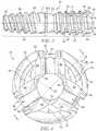
- FIG. 1is an isometric view of a first embodiment of an orthopedic implant taken generally from a first end of the implant;
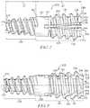
- FIG. 2is an elevational view of a first side of the implant of FIG. 1 ;
- FIG. 3is an elevational view of a second side of the implant of FIG. 1 , wherein the second side is opposite the first side depicted in FIG. 2 ;
- FIG. 4is an elevational view of the first end of the implant of FIG. 1 ;
- FIG. 5is a cross-sectional view of the implant of FIG. 1 taken generally along the lines 5 - 5 of FIG. 4 ;
- FIG. 6is an isometric view of a second embodiment of an orthopedic implant taken generally from a first end of the implant;
- FIG. 7is an elevational view of a first side of the implant of FIG. 6 ;
- FIG. 8is an elevational view of a second side of the implant of FIG. 6 , wherein the second side is opposite the first side depicted in FIG. 7 ;
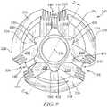
- FIG. 9is an elevational view of the first end of the implant of FIG. 6 ;
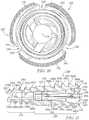
- FIG. 10is an elevational view of a second end of the implant of FIG. 7 , wherein the second end is opposite the first end;
- FIG. 11is a cross-sectional view of the implant of FIG. 6 taken generally along the lines 11 - 11 of FIG. 9 ;
- FIG. 12is a view depicting a tap advanced over a distal Kirschner wire (K-wire) into a middle phalanx of a patient during a first method of implantation of an orthopedic implant disclosed herein;
- K-wiredistal Kirschner wire
- FIG. 13is a view depicting a proximal K-wire inserted into a center of a proximal phalanx of a patient and a drill advanced over the K-wire during the first method of implantation of an orthopedic implant;
- FIG. 14Ais a view depicting a second end of a distal segment of an orthopedic implant threaded into the middle phalanx of a patient during the first method of implantation of an orthopedic implant utilizing an implantation tool;
- FIG. 14Bis a perspective view of a drive end of the implantation tool shown in use in FIG. 14A , wherein the implantation tool is utilized to thread the distal segment of the orthopedic implant into the middle phalanx;
- FIG. 15is a view depicting insertion of a barbed anchor disposed at a first end of a proximal segment of an orthopedic implant into a pre-drilled hole in the proximal phalanx of the patient during the first method of implantation of an orthopedic implant;
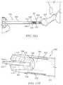
- FIG. 16is a view depicting a method of removing a distal segment of an orthopedic implant in which a threaded tool is utilized to tap an inner surface of the distal segment;
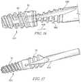
- FIG. 17is a view depicting a method of removing an orthopedic implant in which a tool having a drive features is utilized in combination with a complementary drive feature within a proximal segment of an orthopedic implant to remove the implant;
- FIGS. 18A and 18Bare views depicting bending axes for orthopedic implants having two and three arms, respectively.
- FIGS. 1-5A first embodiment of an orthopedic implant 20 suitable for treatment and correction of hammertoe is depicted in FIGS. 1-5 .
- the implant 20generally includes a pin-shaped body 22 extending along a longitudinal axis 24 and further includes a proximal segment 26 terminating in a first end 28 and a distal segment 30 terminating in a second end 32 .
- the proximal and distal segments 26 , 30may be integral with one another and joined at a central, narrowed segment 34 of the implant 20 .
- the proximal segment 26 of the body 22may generally comprise the central, narrowed segment 34 and three spring arms 36 that form a barbed anchor 38 and which extend away from the central, narrowed segment 34 . While the segment 34 is depicted as being narrowed, the segment 34 may alternatively not be narrowed or may have a constant outer diameter.
- each of the arms 36is separated from adjacent arms 36 by a channel 40 .
- Helical threading 41may be disposed about outer edges or surfaces 42 of each of the arms 36 and may continue between arms 36 (despite the existence of channels 40 therebetween).
- Each of the arms 36is formed by opposing side edges 44 that, with side edges 44 of adjacent arms 36 , form the channels 40 .
- each side edge 44is formed of a straight segment 46 that is generally parallel to a longitudinal axis 24 of the implant 20 and a tapered segment 50 that tapers outwardly from the straight segment 46 at an angle A 1 of greater than 0 degrees to a tip forming a flattened edge 54 .
- each arm 36further includes a generally cylindrical inner edge 56 ( FIG. 4 ) that tapers outwardly from an inner, generally cylindrical surface 57 of the proximal segment 26 .
- the tapered segment 50 and the inner edge 56are tapered to thin out the arms 36 to provide a desired stiffness and even stress distribution for each of the arms 36 .
- three arms 36provides more resistance to bending of the arms 36 along various axes that are perpendicular to the longitudinal axis 24 . Less bending equates to higher contact forces and improved fixation. Three arms 36 also stabilize the bone in which implantation occurs more than two arms, since two arms leave a weak bending axis.
- a number of hammertoe implant designsincorporate two spring arms for retention in the proximal phalanx, the middle phalanx, or both. Designs with two arms are intrinsically easier to manufacture through machining and may be easier to insert into the bone, as well. It has been discovered in the present invention that designs with multiple arms, for example, those with an odd number of arms, impart a strong advantage to implant fixation in the bone. Implant fixation into the bone is a common failure mode because bone in older hammertoe patients is oftentimes osteopenic and poorly supports an interface with the implant. The key to implant stability is the ability of the implant to uniformly impart stresses to the underlying bone.
- the loading vector for a hammertoe implantis predominantly in the dorsal-plantar direction as the foot moves through the gait cycle, however, complex tri-axial stresses also occur in all planes as the foot pushes laterally or moves over uneven surfaces.
- the objective of the implant designershould be to create a design that retains strength and fixation even in a tri-axial stress state.
- a two-arm implant designas seen in FIG. 18A , has a weak bending axis 55 a on a plane of symmetry between the two arms.
- This weak axis 55 aimparts a deficiency to the design in resisting tri-axial stresses, particularly when the dorsal-plantar loading vector is aligned perpendicularly to a vector of the arm spring force 59 a .
- the spring armscontribute little to the stability of the implant in the bone.
- a three-arm implant designstill has weak bending axis 55 b , but the weak bending axis 55 b is not as weak as the weak bending axis 55 a of the two-arm design since there are now arms at more angular positions along a diameter of the implant. Even if a weak axis 55 b of the implant is aligned with the dorsal-plantar loading vector, there are portions of the adjacent spring arms that directly contribute to resistance on the loading vector. This advantage is shared by all arm designs having three or more arms, although odd-numbered arm designs convey a particular evenness between the strong and weak axes.
- the dorsal-plantar loading vectoris not aligned perpendicularly to the vector of the arms spring force 59 b .
- An additional advantage of a three-arm designis that it self-centers in a center of a hole in the bone in which it is implanted.
- the inner surface 57 of the proximal segment 26has an inner diameter 58 that does not vary along a first section 62 that includes both the central, narrowed segment 34 and a portion of the arms 36 .
- the inner surface 58further includes a second section 64 that includes the generally cylindrical surface 57 of the arms 36 and which has a diameter 65 that increases along the longitudinal axis 24 from the central segment 34 toward the first end 28 .
- the arms 36as seen in FIG. 6 , include outer edges 42 that, due to the helical threading 41 , have minor diameters 66 a - 66 e and major diameters 68 a - 68 e .
- the minor diameters 66 a - 66 e of the helical threading 41may be constant in that the diameters thereof do not vary along a length of the threading 41 .
- the major diameters 68 a - 68 e of the helical threading 41may increase from a first major diameter 68 a closest the central segment 34 toward the first end 28 of the proximal segment 30 . More particularly, a major diameter 68 a of the threading 41 may be smaller than each of the other major diameters 68 b - 68 e and the major diameters 68 b - 68 e may each increase between the central segment 34 and the first end 28 .
- An increasing major diameter 68 a - 68 emaximizes bony contact during insertion of the second end 28 of the implant 20 into a proximal phalanx, as discussed in more detail below.
- two or more consecutive or non-consecutive major diameters 68 a - 68 emay be increasing between the major diameter 68 a and the major diameter 68 e and/or two or more consecutive or non-consecutive major diameters 68 a - 68 e may be the same.
- the distal segment 30includes an inner cylindrical surface 80 having an inner diameter 82 .
- the inner diameter 82may be the same or different than the inner diameter 58 of the proximal segment 26 .
- Helical threading 84may be disposed on an outer surface 86 of all or a portion of the distal segment 30 .
- the helical threading 84includes minor diameters 88 a - 88 e and major diameters 92 a - 92 e , wherein the minor diameters 88 a - 88 e may increase along the longitudinal axis 24 of the implant 20 between the second end 32 and the first end 28 .
- a minor diameter 88 a of the threading 84may be smaller than each of the other minor diameters 88 b - 88 e and the minor diameters 88 a - 88 e may increase between minor diameter 88 a and minor diameter 88 e .
- Increasing minor diameters 88 a - 88 eprovide tactile feedback when implanting the distal segment 30 of the implant 20 into a middle phalanx, as discussed in greater detail below.
- two or more consecutive or non-consecutive minor diameters 88 a - 88 emay increase between minor diameter 88 a and minor diameter 88 e and/or two or more consecutive or non-consecutive minor diameters 88 a - 88 e may be same.
- Major diameters 92 a - 92 e of the helical threading 84may increase in diameter from the major diameter 92 a to the major diameter 92 e or the major diameters 92 a - 92 e may be the same.
- two or more consecutive or non-consecutive major diameters 92 a - 92 emay be increasing between the major diameters 92 a and the major diameter 92 e and/or two or more consecutive or non-consecutive major diameters 92 a - 92 e may be the same.
- any number of threadsmay be present depending on a particular application for the implant 20 .
- FIGS. 6-11A second embodiment of an orthopedic implant 220 suitable for treatment and correction of hammertoe is depicted in FIGS. 6-11 .
- the implant 220generally includes a pin-shaped body 222 extending along a longitudinal axis 224 and further includes a proximal segment 226 terminating in a first end 228 and a distal segment 230 terminating in a second end 232 .
- the proximal and distal segments 226 , 230may be integral with one another and joined at a central, cylindrical flattened segment 234 of the implant 220 .
- the proximal segment 226 of the body 222may generally comprise the central flattened segment 234 and three arms 236 that form a barbed anchor 238 and which extend away from the central, flattened segment 234 .
- each of the arms 236is separated from adjacent arms 236 by a channel 240 .
- Helical threading 241may be disposed about outer edges or surfaces 242 of each of the arms 236 and may continue between arms 236 (despite the existence of channels 240 therebetween).
- Each of the arms 236is formed by opposing side edges 244 that, with side edges 244 of adjacent arms 236 , form the channels 240 .
- each side edge 244tapers outwardly at an angle A 2 of greater than 0 degrees to a tip forming a flattened edge 254 .
- the angle A 2may be between about 1 degree and about 15 degrees.
- each arm 236further includes an inner, generally cylindrical edge 256 that tapers outwardly from an inner, generally cylindrical surface 258 of the proximal segment 226 .
- the inner surface 258 of the proximal segment 226has an inner diameter 259 that may not vary along a first section 262 and that may include both the central segment 234 and a portion of the arms 236 .
- the inner diameter 258may further include a second section 264 that includes at least a portion of the arms 236 and which has a diameter 265 that increases along the longitudinal axis 224 from the central segment 234 toward the first end 228 .
- the arms 236as seen in FIG. 11 include helical threading 241 that has minor diameters 266 a - 266 e and major diameters 268 a - 268 e .
- the minor diameters 266 a - 266 e of the helical threading 41may be constant in that the diameters thereof do not vary along a length of the threading 241 or the minor diameters 266 a - 266 e may have different or varying diameters.
- the major diameters 268 a - 268 e of the helical threading 41may be constant in that the diameters thereof do not vary along a length of the threading 241 or the major diameters 268 a - 268 e may have different or varying diameters. In illustrative embodiments and similar to the embodiment of FIGS.
- the major diameters 268 a - 286 emay increase from a first major diameter 268 a closest the central segment 234 toward the first end 228 of the proximal segment 230 .
- two or more consecutive or non-consecutive major diameters 268 a - 268 emay be increasing between the major diameter 268 a and the major diameter 268 e and/or two or more consecutive or non-consecutive major diameters 268 a - 268 e may be the same.
- the distal segment 230includes an inner cylindrical surface 280 having an inner diameter 282 .
- the inner diameter 282may be constant or may vary along the longitudinal axis 224 .
- the inner diameter 282may be the same as or less than the inner diameter 259 of the proximal segment 226 .
- Helical threading 284may be disposed on an outer surface 286 of all or a portion of the distal segment 230 .
- a minor diameter 288 a - 288 e of the helical threading 284may be the same for each thread or may increase along the longitudinal axis 224 of the implant 220 from the second end 232 toward the first end 228 , as discussed above with respect to the embodiment of FIGS.
- two or more consecutive or non-consecutive minor diameters 288 a - 288 emay be increasing between the minor diameter 288 a and the minor diameters 288 e and/or two or more consecutive or non-consecutive minor diameters 288 a - 288 e may be the same.
- Major diameters 292 a - 292 e of the helical threading 284may increase in diameter from the major diameter 292 a to the major diameter 292 e or the major diameters 292 a - 292 e may be the same. Still alternatively, two or more consecutive or non-consecutive major diameters 292 a - 292 e may be increasing between the major diameters 292 a and the major diameter 292 e and/or two or more consecutive or non-consecutive major diameters 292 a - 292 e may be the same.
- any number of threadsmay be present depending on a particular application for the implants 20 , 220 .
- proximal interphalanxal (PIP) joint of the patientis opened using, for example, a dorsal approach.
- a head of a proximal phalanx 104 of the patientis prepared by reaming until bleeding bone is reached, for example, using a proximal phalanx reamer and a base of a middle phalanx 100 of the patient is also reamed until bleeding bone is reached, for example, using a middle phalanx reamer.
- a distal K-wiremay be inserted into a center of the middle phalanx 400 . As seen in FIG.
- tap 410 of the appropriate size 410is selected for the desired implant size and, using firm axial pressure, the tap 410 is advanced over the distal K-wire into the middle phalanx 100 until a laser line 412 on the tap 410 is level with an outer surface 414 of the middle phalanx 400 .
- a proximal K-wire 416may be inserted into a center of the proximal phalanx 404 , as seen in FIG. 13 .
- the K-wire 416may be introduced at a 10 degree angle plantar to a medial axis of the proximal phalanx 404 .
- An appropriate drill sizemay be selected and advanced over the K-wire 416 into the proximal phalanx 404 until a laser line 420 on the drill 418 is level with an outer surface 422 of the proximal phalanx 404 , as seen in FIG. 13 , and the proximal K-wire 416 may be removed after drilling.
- the second end 32 , 232 of the distal segment 30 , 230 of either implant 20 , 220is threaded into the middle phalanx 400 of the patient, as seen in FIG. 14A , using an implantation tool 500 , until an increase in torque indicates firm seating of the implant 20 , 220 .
- an outer edge of the middle phalanx 400may be aligned with a laser line 402 positioned between the proximal and distal segments 26 or 226 , 30 or 230 and should be facing dorsally.
- the laser line 402is formed of one or more of a black burn, engraving, one or more dyes, or any other suitable substance capable of creating a line, marker, or other indicator.
- the laser line 402provides guidance to a surgeon or other healthcare professional such that the distal segment 30 , 230 of the implant 20 , 220 is threaded into the middle phalanx 400 to an optimal or ideal depth.
- the laser lines on the tap 410 and the drill 418additionally prepare the bone for insertion of the implant 20 , 220 to an appropriate depth.
- the implantation tool 500may include a generally cylindrical body 502 , although, the body 502 need not be cylindrical. Three arms 504 extend outwardly from a first end 506 of the body 502 . Each of the arms 504 includes a wider based 508 that tapers into a narrowed tip 510 . The arms 504 are sized and shaped to be complementary to and fit within the channels 40 , 240 formed by the arms 36 , 236 of the implant 20 , 220 , as seen in FIG. 14A .
- the implantation tool 500may retain the implant 20 , 220 on the first end 506 by, for example, an interference fit. In other illustrative embodiments, the implantation tool 500 may fit within the implant 20 , 220 , but may not retain the implant 20 , 220 on the first end 506 .
- an outer diameter of the arms 504 of the implantation tool 500is fully within an outer or major diameter of the threads 68 a - 68 e , 268 a - 268 e .
- Each of the arms 504may also include a laser mark 512 that denote which way the implant arms 36 , 236 are oriented.
- the implantation tool 500may include a similar number of arms.
- the proximal segment 26 , 226 of the implant 20 , 220is aligned with a proximal phalanx 404 of the patient. More specifically, the barbed anchor 38 , 238 at the first end 28 , 228 of the proximal segment 26 , 226 is aligned with and inserted into the pre-drilled hole in the proximal phalanx 404 , as seen in FIG. 15 . The proximal segment 26 , 226 is thereafter pressed into the proximal phalanx 404 . Once both the proximal and distal segments 26 or 226 , 30 or 230 are implanted within the proximal and middle phalanges 404 , 400 , respectively, a typical surgical procedure is used to close the patient.
- implantssuch as implant 20 , 220 or any of the implants disclosed herein, must be removed and replaced (during, for example, a revision surgical procedure). It can be very difficult to remove the distal and/or proximal segments 30 or 230 , 26 or 226 from the middle and proximal phalanges 400 , 404 , respectively.
- the implant 20 , 220may be provided with features that allow for easier removal of the implant 20 , 220 from the middle and proximal phalanges 400 , 404 .
- the implant 20 , 220may be manufactured of a polymeric material, for example, ultra-high molecular weight polyethylene (UHMWPE), polyetheretherketone (PEEK), or any other suitable polymeric material.
- UHMWPEultra-high molecular weight polyethylene
- PEEKpolyetheretherketone
- the central segment 34 , 234 of the implant 20 , 220may be cut to sever the proximal and distal segments 26 or 226 , 30 or 230 from one another.
- the central segment 34 , 234may be cut at a point 130 adjacent the distal segment 30 , 230 .
- a tool 440that is made of a high-strength material, for example, stainless steel, having threading 442 may be threaded into the distal segment 30 .
- the threading 442 on the tool 440taps out the inner cylindrical surface 80 of the distal segment 30 such that opposing threads are created therein.
- the tool 440may be threaded or pulled in a direction 444 opposite the direction of threading to remove the distal segment 30 from the middle phalanx 400 .
- the tool 440may be threaded into the proximal segment 26 , for example, such that the threading 442 on the tool 440 taps out an inner surface 446 of the central segment 34 and/or the proximal segment 26 , thereby creating opposing threads therein.
- the tool 440may be threaded or pulled in a direction opposite the direction of threading to remove the proximal segment 26 from the proximal phalanx 404 .
- the implantfor example, the implant 220 , may include a proximal segment 226 having an internal drive feature 450 (see FIG. 9 ) that mates with a tool 452 such that, upon rotation of the tool 452 , the distal segment 230 may be threaded out of the bore in which it was implanted.
- the drive feature 450may be comprised of a hexalobe bore formed by the cylindrical inner edge 256 that form semi-cylindrical channels and portions of the central segment 34 that form semi-cylindrical channels.
- the drive feature 450may include any suitable feature(s) or geometr(ies) configured to accept a tool and allows for rotation of the implant 220 using the tool 452 . While six semi-cylindrical channels are depicted in FIG. 9 , any suitable number of semi-cylindrical channels may be utilized.
- any of the implants disclosed hereinmay be manufactured in different sizes, for example, for differently-sized phalanges of the same foot or phalanges of persons with differently-sized feet, toes, and/or phalanges.
- three or more differently-sized implantsmay be provided, for example, small, medium, and large implants or small, medium, large, and extra-large implants.
- an overall length of the small implantmay be 13 millimeters, a proximal length L 1 may be 7 millimeters, and a distal length L 2 may be 6 millimeters.
- an overall length of the medium implantmay be 14 millimeters, the proximal length L 1 may be 7 millimeters, and the distal length L 2 may be 7 millimeters. Still further, an overall length of the large implant may be 15 millimeters, the proximal length L 1 may be 7 millimeters, and the distal length may be 8 millimeters. In other embodiments, the overall length of one or more implants may be between about 5 millimeters and about 20 millimeters.
- any of the implants disclosed hereinmay be manufactured of one or more of metal, ultra-high molecular weight polyethylene (UHMWPE), ceramic, polyetheretherketone (PEEK), or any other suitable material or materials.
- UHMWPEultra-high molecular weight polyethylene
- PEEKpolyetheretherketone
- implants disclosed in detail hereinare discussed as being suitable for treatment and correction of hammertoe, the implants disclosed herein may be utilized for treatment and/or correction of other conditions, for example, other conditions in the foot or hand and/or conditions related to other joints.
- any one or more features of any of the implant disclosed hereinmay be incorporated (alone or in combination) into any of the other implants disclosed herein.
Landscapes
- Health & Medical Sciences (AREA)
- Orthopedic Medicine & Surgery (AREA)
- Life Sciences & Earth Sciences (AREA)
- Surgery (AREA)
- Animal Behavior & Ethology (AREA)
- General Health & Medical Sciences (AREA)
- Biomedical Technology (AREA)
- Heart & Thoracic Surgery (AREA)
- Veterinary Medicine (AREA)
- Engineering & Computer Science (AREA)
- Public Health (AREA)
- Molecular Biology (AREA)
- Nuclear Medicine, Radiotherapy & Molecular Imaging (AREA)
- Medical Informatics (AREA)
- Neurology (AREA)
- Oral & Maxillofacial Surgery (AREA)
- Dentistry (AREA)
- Transplantation (AREA)
- Cardiology (AREA)
- Vascular Medicine (AREA)
- Prostheses (AREA)
- Physical Education & Sports Medicine (AREA)
Abstract
Description
Claims (21)
Priority Applications (4)
| Application Number | Priority Date | Filing Date | Title |
|---|---|---|---|
| US15/669,370US10702318B2 (en) | 2015-03-03 | 2017-08-04 | Orthopedic implant and methods of implanting and removing same |
| US16/891,732US11672576B2 (en) | 2015-03-03 | 2020-06-03 | Orthopedic implant and methods of implanting and removing same |
| US18/195,024US12383318B2 (en) | 2015-03-03 | 2023-05-09 | Orthopedic implant and methods of implanting and removing same |
| US19/024,437US20250152212A1 (en) | 2015-03-03 | 2025-01-16 | Orthopedic Implant And Methods Of Implanting And Removing Same |
Applications Claiming Priority (2)
| Application Number | Priority Date | Filing Date | Title |
|---|---|---|---|
| US14/637,032US9757168B2 (en) | 2015-03-03 | 2015-03-03 | Orthopedic implant and methods of implanting and removing same |
| US15/669,370US10702318B2 (en) | 2015-03-03 | 2017-08-04 | Orthopedic implant and methods of implanting and removing same |
Related Parent Applications (1)
| Application Number | Title | Priority Date | Filing Date |
|---|---|---|---|
| US14/637,032DivisionUS9757168B2 (en) | 2015-03-03 | 2015-03-03 | Orthopedic implant and methods of implanting and removing same |
Related Child Applications (1)
| Application Number | Title | Priority Date | Filing Date |
|---|---|---|---|
| US16/891,732DivisionUS11672576B2 (en) | 2015-03-03 | 2020-06-03 | Orthopedic implant and methods of implanting and removing same |
Publications (2)
| Publication Number | Publication Date |
|---|---|
| US20170333095A1 US20170333095A1 (en) | 2017-11-23 |
| US10702318B2true US10702318B2 (en) | 2020-07-07 |
Family
ID=56849493
Family Applications (5)
| Application Number | Title | Priority Date | Filing Date |
|---|---|---|---|
| US14/637,032ActiveUS9757168B2 (en) | 2015-03-03 | 2015-03-03 | Orthopedic implant and methods of implanting and removing same |
| US15/669,370ActiveUS10702318B2 (en) | 2015-03-03 | 2017-08-04 | Orthopedic implant and methods of implanting and removing same |
| US16/891,732Active2035-09-10US11672576B2 (en) | 2015-03-03 | 2020-06-03 | Orthopedic implant and methods of implanting and removing same |
| US18/195,024Active2035-08-21US12383318B2 (en) | 2015-03-03 | 2023-05-09 | Orthopedic implant and methods of implanting and removing same |
| US19/024,437PendingUS20250152212A1 (en) | 2015-03-03 | 2025-01-16 | Orthopedic Implant And Methods Of Implanting And Removing Same |
Family Applications Before (1)
| Application Number | Title | Priority Date | Filing Date |
|---|---|---|---|
| US14/637,032ActiveUS9757168B2 (en) | 2015-03-03 | 2015-03-03 | Orthopedic implant and methods of implanting and removing same |
Family Applications After (3)
| Application Number | Title | Priority Date | Filing Date |
|---|---|---|---|
| US16/891,732Active2035-09-10US11672576B2 (en) | 2015-03-03 | 2020-06-03 | Orthopedic implant and methods of implanting and removing same |
| US18/195,024Active2035-08-21US12383318B2 (en) | 2015-03-03 | 2023-05-09 | Orthopedic implant and methods of implanting and removing same |
| US19/024,437PendingUS20250152212A1 (en) | 2015-03-03 | 2025-01-16 | Orthopedic Implant And Methods Of Implanting And Removing Same |
Country Status (1)
| Country | Link |
|---|---|
| US (5) | US9757168B2 (en) |
Families Citing this family (25)
| Publication number | Priority date | Publication date | Assignee | Title |
|---|---|---|---|---|
| FR2884406B1 (en) | 2005-04-14 | 2008-10-17 | Memometal Technologies Soc Par | INTRAMEDULAR OSTEOSYNTHESIS DEVICE OF TWO BONE PARTS, IN PARTICULAR HAND AND / OR FOOT |
| FR2913876B1 (en) | 2007-03-20 | 2009-06-05 | Memometal Technologies Soc Par | OSTEOSYNTHESIS DEVICE |
| FR2935601B1 (en) | 2008-09-09 | 2010-10-01 | Memometal Technologies | INTRAMEDULLARY IMPLANT RESORBABLE BETWEEN TWO BONE OR TWO BONE FRAGMENTS |
| US9724138B2 (en)* | 2011-09-22 | 2017-08-08 | Arthrex, Inc. | Intermedullary devices for generating and applying compression within a body |
| US9554914B2 (en)* | 2011-12-12 | 2017-01-31 | Wright Medical Technology, Inc. | Fusion implant |
| US9480515B2 (en) | 2012-07-12 | 2016-11-01 | Exsomed International IP, LLC | Metacarpal bone stabilization device |
| WO2015050895A1 (en) | 2013-10-02 | 2015-04-09 | Exsomed Holding Company Llc | Full wrist fusion device |
| WO2015090954A1 (en)* | 2013-12-17 | 2015-06-25 | Stichting Katholieke Universiteit | Intramedullary device for mid-shaft clavicle fractures |
| WO2016044053A1 (en) | 2014-09-19 | 2016-03-24 | Crossroads Extremity Systems, Llc | Bone fixation implant and means of fixation |
| US9757168B2 (en) | 2015-03-03 | 2017-09-12 | Howmedica Osteonics Corp. | Orthopedic implant and methods of implanting and removing same |
| WO2016186847A1 (en) | 2015-05-19 | 2016-11-24 | Exsomed International IP, LLC | Distal radius plate |
| US20170151061A1 (en)* | 2015-09-10 | 2017-06-01 | Vilex In Tennessee, Inc. | Arthrodesis Implant and System Therefor |
| US10292745B2 (en)* | 2015-10-07 | 2019-05-21 | Arthrex, Inc. | Devices for generating and applying compression within a body |
| US10245091B2 (en)* | 2015-12-30 | 2019-04-02 | Exsomed Holding Company, Llc | Dip fusion spike screw |
| US11147604B2 (en) | 2016-01-12 | 2021-10-19 | ExsoMed Corporation | Bone stabilization device |
| FR3048871A1 (en)* | 2016-03-16 | 2017-09-22 | Neosteo | MEDICAL IMPLANT AND ASSEMBLY COMPRISING SUCH A MEDICAL IMPLANT AND A PREHENDER OF SAID IMPLANT |
| US10194923B2 (en) | 2016-05-10 | 2019-02-05 | Exsomed International IP, LLC | Tool for percutaneous joint cartilage destruction and preparation for joint fusion |
| US11191645B2 (en) | 2017-09-05 | 2021-12-07 | ExsoMed Corporation | Small bone tapered compression screw |
| US11147681B2 (en) | 2017-09-05 | 2021-10-19 | ExsoMed Corporation | Small bone angled compression screw |
| JP2020532407A (en) | 2017-09-05 | 2020-11-12 | エクソームド コーポレーションExsomed Corporation | Threaded intramedullary nail for radial cortex fixation |
| US11246712B2 (en)* | 2018-03-01 | 2022-02-15 | Paragon 28, Inc. | Implants, systems, and methods of use and assembly |
| WO2019169319A1 (en)* | 2018-03-01 | 2019-09-06 | Paragon 28, Inc. | Implants and methods of use and assembly |
| EP3781057A1 (en) | 2018-04-18 | 2021-02-24 | GLW, Inc. | Removable orthopedic screws |
| WO2021231329A1 (en) | 2020-05-11 | 2021-11-18 | Gensano Llc | Cannulated bone implant |
| US20230031466A1 (en)* | 2021-07-29 | 2023-02-02 | Trimed, Incorporated | Bone implant and method of controlling the bone implant |
Citations (240)
| Publication number | Priority date | Publication date | Assignee | Title |
|---|---|---|---|---|
| US1095054A (en) | 1913-08-26 | 1914-04-28 | Robert Wiesenfeld | Fish-tongs. |
| US1517334A (en) | 1924-02-28 | 1924-12-02 | Eda L Young | Comb |
| US1893864A (en) | 1932-02-26 | 1933-01-10 | Kocher Philip | Comb |
| US2580821A (en) | 1950-10-21 | 1952-01-01 | Nicola Toufick | Spring impactor bone plate |
| US2984248A (en) | 1958-04-04 | 1961-05-16 | Delamere Co Inc | Light weight hair retaining fine tooth metal comb |
| US3462765A (en) | 1967-01-06 | 1969-08-26 | Dow Corning | Surgically implantable prosthetic joint |
| US3466669A (en) | 1966-09-20 | 1969-09-16 | Univ Iowa | Intramedullary finger joint prosthesis |
| US3593342A (en) | 1969-01-27 | 1971-07-20 | Cutter Lab | Prosthetic joint |
| US3681786A (en) | 1970-07-13 | 1972-08-08 | Medical Eng Corp | Solid human prosthesis of varying consistency |
| US3739403A (en) | 1970-10-09 | 1973-06-19 | F Nicolle | Prosthetic joint having a tissue ingrowth preventive capsule |
| US3805302A (en) | 1971-10-08 | 1974-04-23 | R Mathys | Finger joint prothesis |
| US3824631A (en) | 1973-05-11 | 1974-07-23 | Sampson Corp | Bone joint fusion prosthesis |
| US3875594A (en) | 1973-08-27 | 1975-04-08 | Dow Corning | Surgically implantable prosthetic joint having load distributing flexible hinge |
| USD243716S (en) | 1975-07-24 | 1977-03-15 | Richards Manufacturing Company, Inc. | Great toe prosthesis |
| US4091806A (en) | 1976-01-13 | 1978-05-30 | Jacob Aginsky | Intramedullary compression nail for the treatment of bone fractures |
| US4158893A (en) | 1976-10-12 | 1979-06-26 | Swanson Alfred B | Protective sleeve for implantable prosthesis and method of protecting the prosthesis |
| US4204284A (en) | 1977-11-16 | 1980-05-27 | Lord Corporation | Joint prosthesis with contoured pin |
| US4237875A (en) | 1979-02-23 | 1980-12-09 | Towmotor Corporation | Dynamic intramedullary compression nailing |
| US4276660A (en) | 1979-05-25 | 1981-07-07 | Laure Prosthetics, Inc. | Carpometacarpal thumb joint |
| US4364382A (en) | 1979-08-23 | 1982-12-21 | Ulrich Mennen | Internal fixation device for bone fractures |
| US4367562A (en) | 1980-06-19 | 1983-01-11 | Georges Gauthier | Joint prosthesis |
| GB2119655A (en) | 1982-05-06 | 1983-11-23 | Nat Res Dev | Endoprosthesis |
| US4485816A (en) | 1981-06-25 | 1984-12-04 | Alchemia | Shape-memory surgical staple apparatus and method for use in surgical suturing |
| USD277509S (en) | 1982-07-01 | 1985-02-05 | Sutter Biomedical Inc. | Great toe metatarsal phalangeal implant |
| USD277784S (en) | 1982-06-25 | 1985-02-26 | Sutter Biomedical, Inc. | Lesser toe metatarsal phalangeal implant |
| US4522200A (en) | 1983-06-10 | 1985-06-11 | Ace Orthopedic Company | Adjustable intramedullar rod |
| JPS60145133A (en) | 1984-01-09 | 1985-07-31 | 工業技術院長 | Bone connection tool |
| USD284099S (en) | 1983-03-14 | 1986-06-03 | Sutter Bio-Medical, Inc. | Great toe metatarsal phalangeal implant |
| US4634382A (en) | 1984-06-07 | 1987-01-06 | Molten Corp. | Attachment for dental prosthesis |
| USD291731S (en) | 1985-05-08 | 1987-09-01 | Zimmer, Inc. | Prosthetic joint implant for a finger or toe or the like |
| US4759768A (en) | 1987-02-11 | 1988-07-26 | Thierry Hermann | Joint prosthesis, in particular finger joint prosthesis |
| US4871367A (en) | 1987-09-03 | 1989-10-03 | Sutter Biomedical Corporation | Surgically implanted prosthesis |
| US4905679A (en) | 1988-02-22 | 1990-03-06 | M P Operation, Inc. | Bone fracture reduction device and method of internal fixation of bone fractures |
| US4955916A (en) | 1989-05-01 | 1990-09-11 | Techmedica, Inc. | Thumb joint prosthesis |
| US4969909A (en) | 1987-10-27 | 1990-11-13 | Barouk Louis S | Articular prosthetic implant with temporary fixing means |
| JPH031854A (en) | 1989-04-25 | 1991-01-08 | Per-Ingvar Branemark | Fixing element for supporting joint mechanism of finger or other reconstitution joint |
| EP0420794A1 (en) | 1989-09-28 | 1991-04-03 | SULZER Medizinaltechnik AG | Finger joint prosthesis |
| US5011497A (en) | 1987-10-29 | 1991-04-30 | Atos Medical Ab | Joint prosthesis |
| US5047059A (en) | 1987-09-28 | 1991-09-10 | Philippe Saffar | Prosthesis for metacarpopealangeal or interphalangeal articulation of the fingers |
| US5062851A (en) | 1989-04-25 | 1991-11-05 | Medevelop Ab | Anchoring element for supporting a joint mechanism of a finger or other reconstructed joint |
| US5074865A (en) | 1988-02-17 | 1991-12-24 | Fahmy Nabil R | Distraction apparatus for maintaining fractured joint orientation |
| US5108443A (en) | 1989-04-25 | 1992-04-28 | Medevelop Ab | Anchoring element for supporting a joint mechanism of a finger or other reconstructed joint |
| US5133761A (en) | 1991-06-12 | 1992-07-28 | Research Development Foundation | Finger joint prosthesis |
| US5179915A (en) | 1992-01-06 | 1993-01-19 | Osteonics Corporation | Anatomically matching intramedullary alignment rod |
| US5190546A (en) | 1983-10-14 | 1993-03-02 | Raychem Corporation | Medical devices incorporating SIM alloy elements |
| US5207712A (en) | 1992-05-07 | 1993-05-04 | Michael Cohen | Absorbable joint implants for the lesser digits and metatarsal phalangeal joints in the surgical correction of the foot |
| US5326364A (en) | 1992-12-16 | 1994-07-05 | Wright Medical Technology, Inc. | Trapezial implant |
| US5360450A (en) | 1992-03-09 | 1994-11-01 | Howmedica International Div.Ne Pfizer Italiana S.P.A. | Prosthesis for the correction of flatfoot |
| US5382251A (en) | 1989-01-31 | 1995-01-17 | Biomet, Inc. | Plug pulling method |
| US5405401A (en) | 1993-10-05 | 1995-04-11 | Orthomet, Inc. | Prosthesis for replacement of joints between long bones in the hand |
| US5405400A (en) | 1993-10-05 | 1995-04-11 | Orthomet, Inc. | Joint prosthesis enabling rotary circumduction |
| US5425777A (en) | 1992-12-23 | 1995-06-20 | Sarkisian; James S. | Artificial finger joint |
| US5425776A (en) | 1992-05-07 | 1995-06-20 | Cohen; Michael | Method of using absorbable joint implants for the lesser digits and metatarsal phalangeal joints in the surgical correction of the foot |
| US5454814A (en) | 1992-09-02 | 1995-10-03 | Orthomed Sarl | Surgical clamp and clamp driving device |
| US5464427A (en) | 1994-10-04 | 1995-11-07 | Synthes (U.S.A.) | Expanding suture anchor |
| US5474557A (en) | 1993-09-21 | 1995-12-12 | Mai; Christian | Multibranch osteosynthesis clip with dynamic compression and self-retention |
| US5480447A (en) | 1992-12-15 | 1996-01-02 | International Polymer Engineering, Inc. | Joint implant |
| USD366114S (en) | 1995-04-21 | 1996-01-09 | Kenji Ohata | Metallic cranial burr hole cover and bone flap fixation plate |
| US5484443A (en) | 1992-01-03 | 1996-01-16 | Wright Medical Technology, Inc. | Instrument for inserting a protective sleeve into the medullary canal of a bone |
| FR2725126A1 (en) | 1994-10-04 | 1996-04-05 | Mai Christian | LIGAMENT IMPLANT WITH SHAPE MEMORY |
| US5507822A (en) | 1993-04-23 | 1996-04-16 | Societe Dite Jbs Societe Anonyme | Ball-and-socket jointed two-part thumb prosthesis |
| USD369412S (en) | 1994-05-03 | 1996-04-30 | Timesh, Inc. | Cranial bone plate |
| US5522903A (en) | 1993-11-10 | 1996-06-04 | Jbs S.A. | Finger prosthesis |
| US5554157A (en) | 1995-07-13 | 1996-09-10 | Fastenetix, L.L.C. | Rod securing polyaxial locking screw and coupling element assembly |
| US5578036A (en) | 1993-12-06 | 1996-11-26 | Stone; Kevin T. | Method and apparatus for fixation of bone during surgical procedures |
| US5634925A (en) | 1993-02-19 | 1997-06-03 | Alphatec Manufacturing, Inc. | Apparatus and method for spinal fixation system |
| WO1997033537A1 (en) | 1996-03-13 | 1997-09-18 | Bramlet Dale G | Arthroplasty joint assembly |
| US5674297A (en) | 1995-12-08 | 1997-10-07 | Lane; Lewis B. | Metacarpophalangeal prosthesis |
| US5690631A (en) | 1996-09-11 | 1997-11-25 | Walter Lorenz Surgical, Inc. | Multi-configurable plating system |
| US5702472A (en) | 1996-12-26 | 1997-12-30 | Huebner; Randall J. | Phalangeal finger joint prosthesis and method |
| JPH103662A (en) | 1996-06-12 | 1998-01-06 | Fuji Photo Film Co Ltd | Manufacture of magnetic recording medium |
| USD388877S (en) | 1994-05-03 | 1998-01-06 | Sofamor Danek Properties, Inc. | Cranial bone plate |
| US5725585A (en) | 1997-02-27 | 1998-03-10 | Zobel; Robert A. | Anatomically correct great toe implant and surgical procedure for implanting the same |
| US5779707A (en) | 1992-11-13 | 1998-07-14 | Bertholet; Maurice | Link piece for bony elements |
| US5782927A (en) | 1996-11-06 | 1998-07-21 | Ascension Orthopedics, Inc. | Metacarpal-phalangeal joint replacement |
| US5824095A (en) | 1996-04-26 | 1998-10-20 | E. I. Du Pont De Nemours And Company | Anatomically neutral joint |
| US5876434A (en) | 1997-07-13 | 1999-03-02 | Litana Ltd. | Implantable medical devices of shape memory alloy |
| US5882444A (en) | 1995-05-02 | 1999-03-16 | Litana Ltd. | Manufacture of two-way shape memory devices |
| US5919193A (en) | 1996-03-14 | 1999-07-06 | Slavitt; Jerome A. | Method and kit for surgically correcting malformations in digits of a finger or toe |
| US5951288A (en) | 1998-07-03 | 1999-09-14 | Sawa; Shlaimon T. | Self expanding dental implant and method for using the same |
| US5958159A (en) | 1997-01-16 | 1999-09-28 | Memometal Industries | Process for the production of a superelastic material out of a nickel and titanium alloy |
| US5984971A (en) | 1995-02-17 | 1999-11-16 | Tecres S.P.A. | Prosthesis for metacarpal-phalangeal and interphalangeal joints in hands or feet |
| US6011497A (en) | 1997-04-01 | 2000-01-04 | Seagate Technology, Inc. | Location dependent maximum transition run length code with alternating code word length and efficient K constraint |
| US6017366A (en) | 1997-04-18 | 2000-01-25 | W. L. Gore & Associates, Inc. | Resorbable interposition arthroplasty implant |
| FR2783702A1 (en) | 1998-09-29 | 2000-03-31 | Maurice Bertholet | Self-locking prosthesis for bone insert has heat activated anchor flanges formed on central core |
| FR2787313A1 (en) | 1998-12-17 | 2000-06-23 | Orsco International | Osteo-synthesis implant has shape memory material inserts to expand into contact with bone fragments |
| US6093188A (en) | 1997-11-10 | 2000-07-25 | Murray; William M. | Adjustable bone fixation plate |
| US6123709A (en) | 1997-07-25 | 2000-09-26 | Jones; Andrew R. | Bone buttress plate and method of using same |
| US6146387A (en) | 1998-08-26 | 2000-11-14 | Linvatec Corporation | Cannulated tissue anchor system |
| FR2794019A1 (en) | 1999-05-26 | 2000-12-01 | Orsco Internat | Ostheosynthesis implant especially useful for long and small bones, comprises body including helicoidal coil of deformable material and means of supporting implant against the proximal and distal fragments of the bone |
| US6162234A (en) | 1993-03-23 | 2000-12-19 | Freedland; Yosef | Adjustable button cinch anchor orthopedic fastener |
| US6197037B1 (en) | 1999-07-29 | 2001-03-06 | John Hunter Hair | Surgical fastener for joining adjacent bone portions |
| US6200330B1 (en) | 1998-11-23 | 2001-03-13 | Theodore V. Benderev | Systems for securing sutures, grafts and soft tissue to bone and periosteum |
| FR2801189A1 (en) | 1999-11-24 | 2001-05-25 | Newdeal | Bone shortening implant, especially for metatarsal bones, has anterior portion with anchoring head and posterior portion sliding into bone canal |
| US6248109B1 (en) | 1998-07-30 | 2001-06-19 | Waldemar Link (Gmbh & Co.) | Implant for interconnecting two bone fragments |
| US6261289B1 (en) | 1998-10-26 | 2001-07-17 | Mark Levy | Expandable orthopedic device |
| US20010025199A1 (en) | 2000-03-21 | 2001-09-27 | Markus Rauscher | Artificial finger joint |
| US6319284B1 (en) | 2000-05-31 | 2001-11-20 | Futura Biomedical Llc | Toe implant |
| US6325805B1 (en) | 1999-04-23 | 2001-12-04 | Sdgi Holdings, Inc. | Shape memory alloy staple |
| US20010049529A1 (en) | 1996-11-12 | 2001-12-06 | Cachia Victor V. | Bone fixation system |
| US6348052B1 (en) | 1996-07-16 | 2002-02-19 | Giacomo J. Sammarco | Internal fixation plate |
| US6352560B1 (en) | 1998-07-03 | 2002-03-05 | Van Straten Beheer B.V. | Joint prosthesis |
| US6383223B1 (en) | 1997-06-18 | 2002-05-07 | BAEHLER ANDRé | Endoprosthesis for a joint, especially a finger, toe or wrist joint |
| US20020055785A1 (en) | 2000-11-03 | 2002-05-09 | Finsbury (Development) Limited | Prosthesis |
| US6386877B1 (en) | 1998-07-30 | 2002-05-14 | Franz Sutter | Implant for holding and/or forming a dental prosthesis or artificial finger joint |
| US6395031B1 (en) | 1998-10-29 | 2002-05-28 | Sdgi Holdings, Inc. | Expandable intervertebral spacers |
| US20020065561A1 (en) | 2000-11-28 | 2002-05-30 | Ogilvie William F. | Interphalangeal joint replacement |
| US20020068939A1 (en) | 1998-10-26 | 2002-06-06 | Expanding Orthopedics Inc. | Expandable orthopedic device |
| US20020082705A1 (en) | 2000-09-22 | 2002-06-27 | Hans-Werner Bouman | Basal finger joint implant |
| US6413260B1 (en) | 1999-08-17 | 2002-07-02 | Pioneer Laboratories, Inc. | Bone connector system |
| US20020099395A1 (en) | 2001-01-19 | 2002-07-25 | Sergio Acampora | Device for fastening a cranial flap to the cranial vault |
| US6428634B1 (en) | 1994-03-31 | 2002-08-06 | Ormco Corporation | Ni-Ti-Nb alloy processing method and articles formed from the alloy |
| US20020133156A1 (en) | 1999-06-10 | 2002-09-19 | Cole J. Dean | Femoral intramedullary rod system |
| US6454808B1 (en) | 1998-01-28 | 2002-09-24 | M-E-System Inc. | Finger joint prosthesis |
| US6458134B1 (en) | 1999-08-17 | 2002-10-01 | Pioneer Laboratories, Inc. | Bone connector system with anti-rotational feature |
| US20020189622A1 (en) | 1999-10-20 | 2002-12-19 | Cauthen Joseph C. | Spinal disc annulus reconstruction method and spinal disc annulus stent |
| US6517543B1 (en) | 1999-08-17 | 2003-02-11 | Pioneer Laboratories, Inc. | Bone connector system with anti-rotational feature |
| US20030040805A1 (en) | 2001-08-27 | 2003-02-27 | Yoshitaka Minamikawa | Artificial joint |
| EP1300122A2 (en) | 2001-10-05 | 2003-04-09 | Depuy Orthopaedics, Inc. | Prosthetic joint component having multiple arcuate bending portions |
| US20030120277A1 (en) | 1998-08-07 | 2003-06-26 | Berger J. Lee | Cannulated internally threaded bone screw with aperatured insert |
| US20030130660A1 (en) | 1998-10-26 | 2003-07-10 | Expanding Orthopedics, Inc. | Expandable orthopedic device |
| US20040002759A1 (en) | 2002-06-28 | 2004-01-01 | Ferree Bret A. | Fusion and arthroplasty devices configured to receive bone growth promoting substances |
| US6692499B2 (en) | 1997-07-02 | 2004-02-17 | Linvatec Biomaterials Oy | Surgical fastener for tissue treatment |
| US6699247B2 (en) | 1997-01-02 | 2004-03-02 | St. Francis Medical Technologies, Inc. | Spine distraction implant |
| US6706045B2 (en) | 1997-05-15 | 2004-03-16 | Howmedica Osteonics Corp. | Clamping connector for spinal fixation systems |
| FR2846545A1 (en) | 2002-10-30 | 2004-05-07 | Bouali Amara | Intramedullar osteosynthesis implant used, eg, for the fixing of finger or toe interphalangeal joints damaged by osteoarthritis, made of memory material and expanding at body temperature to provide a secure grip |
| US20040093081A1 (en) | 2001-01-15 | 2004-05-13 | Anders Nilsson | Implant for reconstruction of joints |
| US6736818B2 (en) | 1999-11-11 | 2004-05-18 | Synthes (U.S.A.) | Radially expandable intramedullary nail |
| US20040138756A1 (en) | 2003-01-09 | 2004-07-15 | Nathan Reeder | Method for preparing radial and carpal bones for a wrist prosthesis |
| US20040220678A1 (en) | 2003-04-29 | 2004-11-04 | Chow Shew Ping | Prosthetic device and method for total joint replacement in small joint arthroplasty |
| US20040230193A1 (en) | 2003-04-18 | 2004-11-18 | Cheung Kenneth M.C. | Fixation device |
| US6896177B2 (en) | 2001-04-11 | 2005-05-24 | Balance Innovations, Llc | Method and computer program for building and replenishing cash drawers with coins |
| US20050119757A1 (en) | 2001-12-12 | 2005-06-02 | Michel Hassler | Trapezium or trapezometacarpal implant |
| US20050124990A1 (en) | 2003-12-09 | 2005-06-09 | Michael Teague | Bone plate holder and screw guide |
| WO2005063149A1 (en) | 2003-12-22 | 2005-07-14 | Memometal Technologies | Interphalangeal and/or metacarpophalangeal prosthesis |
| US20050216015A1 (en)* | 2004-03-27 | 2005-09-29 | Winfried Kreidler | System with a screwdriver and a bone screw |
| US20050251265A1 (en) | 2004-05-07 | 2005-11-10 | Calandruccio James H | Trapezium implant for thumb and method |
| WO2005104961A1 (en) | 2004-04-16 | 2005-11-10 | Memometal Technologies | Clamp for positioning a superelastic osteosynthesis clip |
| US20050261768A1 (en) | 2004-05-21 | 2005-11-24 | Trieu Hai H | Interspinous spacer |
| US20050283159A1 (en) | 2004-06-17 | 2005-12-22 | Bouali Amara | Intramedullary osteosynthesis implant |
| US20060015181A1 (en) | 2004-07-19 | 2006-01-19 | Biomet Merck France (50% Interest) | Interspinous vertebral implant |
| US20060052878A1 (en) | 2004-08-18 | 2006-03-09 | Reinhold Schmieding | Modular joint replacement implant with hydrogel surface |
| US20060052725A1 (en) | 2004-09-03 | 2006-03-09 | Santilli Albert N | Small joint orthopedic implants and their manufacture |
| US20060074492A1 (en) | 2004-09-09 | 2006-04-06 | Theo Frey | Endoprosthesis for a metatarsophalangeal joint |
| US20060085075A1 (en) | 2004-10-04 | 2006-04-20 | Archus Orthopedics, Inc. | Polymeric joint complex and methods of use |
| US7041106B1 (en) | 2001-06-15 | 2006-05-09 | Biomet, Inc. | Interphalangeal fusion pin |
| US7044953B2 (en) | 2003-02-27 | 2006-05-16 | Stryker Leibinger Gmbh & Co. Kg | Compression bone screw |
| WO2006109004A1 (en) | 2005-04-14 | 2006-10-19 | Memometal Technologies | Intramedullar osteosynthetic device of two bone parts, in particular of the hand and/or foot |
| US20060247787A1 (en) | 2003-06-27 | 2006-11-02 | Rydell Mark A | Method and system for toe arthroplasty |
| US20070038303A1 (en) | 2006-08-15 | 2007-02-15 | Ebi, L.P. | Foot/ankle implant and associated method |
| GB2430625A (en) | 2005-09-30 | 2007-04-04 | Andrew Malcolm Jackson | Joint fusion peg |
| US20070142920A1 (en) | 2005-12-20 | 2007-06-21 | Niemi Willard J | Metatarsal implant |
| US20070156241A1 (en) | 2004-08-09 | 2007-07-05 | Reiley Mark A | Systems and methods for the fixation or fusion of bone |
| US7240677B2 (en) | 2003-02-03 | 2007-07-10 | Biomedical Enterprises, Inc. | System and method for force, displacement, and rate control of shaped memory material implants |
| US20070162018A1 (en) | 2002-07-22 | 2007-07-12 | Jensen David G | Orthopedic systems |
| US20070185584A1 (en) | 2006-02-02 | 2007-08-09 | Kaufmann Robert A | Small joint hemiarthroplasty |
| US20070198088A1 (en) | 2003-10-17 | 2007-08-23 | Lutz Biedermann | Flexible implant |
| US20070213831A1 (en) | 2004-07-09 | 2007-09-13 | De Cubber Jan | Finger or toe prosthesis |
| US20070239158A1 (en) | 2006-04-10 | 2007-10-11 | Sdgi Holdings, Inc. | Elastic plates for spinal fixation or stabilization |
| JP2007530194A (en) | 2004-03-31 | 2007-11-01 | オルトフィックス ソシエタ ア レスポンサビリタ リミタータ | Bone marrow insertion spear with shape memory nail |
| US7291175B1 (en) | 2005-01-06 | 2007-11-06 | David J Gordon | Metatarsal phalangeal implant with locking screw |
| US20080039949A1 (en) | 2004-12-03 | 2008-02-14 | Larissa Meesenburg | Artificial Joint Element And Gripping Tool Equipped With The Same |
| WO2008057404A2 (en) | 2006-11-01 | 2008-05-15 | Acumed Llc | Orthopedic connector system |
| EP1923012A1 (en) | 2006-11-16 | 2008-05-21 | Newdeal | Interphalangeal arthrodesis implant, corresponding surgical kit and manufacturing method |
| US20080154385A1 (en) | 2006-06-20 | 2008-06-26 | Finsbury (Development) Limited | Prosthesis |
| US20080195219A1 (en) | 2007-02-08 | 2008-08-14 | Zimmer, Inc. | Hydrogel proximal interphalangeal implant |
| US20080221698A1 (en) | 2005-08-18 | 2008-09-11 | Mayo Foundation For Medical Education And Research | Semi-Constrained 1st Carpometacarpal Implant Arthroplasty |
| US20080221697A1 (en) | 2007-03-06 | 2008-09-11 | Robert Graser | Hemi-implant for first metatarsophalangeal joint |
| WO2008112308A1 (en) | 2007-03-12 | 2008-09-18 | Stout Medical Group, L.P. | Expandable attachment device and method |
| US20080234763A1 (en) | 2007-03-16 | 2008-09-25 | Patterson Chad J | Surgical compression bone screw |
| US20080269908A1 (en) | 2007-04-27 | 2008-10-30 | Piper Medical, Inc. | Carpometacarpal (cmc) joint arthoplasty implants and related jigs, medical kits and methods |
| WO2008129214A2 (en) | 2007-03-20 | 2008-10-30 | Memometal Technologies | Osteosynthesis device |
| US20090005821A1 (en) | 2007-06-29 | 2009-01-01 | Spineworks Medical, Inc. | Methods and devices for stabilizing bone compatible for use with bone screws |
| US20090012564A1 (en) | 2007-03-07 | 2009-01-08 | Spineworks Medical, Inc. | Transdiscal interbody fusion device and method |
| WO2009103085A1 (en) | 2008-02-14 | 2009-08-20 | Arizona Heart Innovative Technologies, Llc | Joint fusion device |
| US7588603B2 (en) | 2003-11-05 | 2009-09-15 | Teknimed | Implantable orthesis and surgical kit for knee arthrodesis |
| US20090254190A1 (en) | 2008-01-07 | 2009-10-08 | Jamy Gannoe | System and method for trapezium bone replacement |
| US20090254189A1 (en) | 2005-10-13 | 2009-10-08 | Aptis Medical, Llc | Wrist prosthesis |
| US7600956B2 (en) | 2006-01-17 | 2009-10-13 | Cobra Anchors Co. Ltd. | Plastic anchor for drywall, plaster, brick and concrete |
| US20100010637A1 (en) | 2007-02-07 | 2010-01-14 | Jean-Pierre Pequignot | Trapezo-metacarpal implant |
| US20100016982A1 (en) | 2006-12-07 | 2010-01-21 | Michael Wayne Solomons | Trapezium prosthesis |
| US20100057214A1 (en) | 2008-09-03 | 2010-03-04 | Mimedx, Inc., Corporation of the State of Florida | Arthrodesis implant for finger joints and related methods |
| US20100121390A1 (en) | 2008-11-10 | 2010-05-13 | Acumed Llc | Partial or complete prosthetic replacement arthroplasty of the distal radioulnar joint |
| US20100131072A1 (en) | 2008-11-25 | 2010-05-27 | Schulte Robert C | Intra-osseus fusion system |
| US20100161068A1 (en) | 2007-07-09 | 2010-06-24 | Zrinski Ag | Prosthesis for part of a joint, with an expandable shaft |
| US20100185295A1 (en) | 2006-06-23 | 2010-07-22 | Implants International Limited | Articulation prosthesis for small bones, in particular for phalangeal, metacarpo-phalangeal or metatarso-phalangeal articulations |
| US7780737B2 (en) | 2004-08-09 | 2010-08-24 | Ortho Id | Ball-type triple-joint implant system for upper or lower limbs |
| US20100228301A1 (en) | 2009-03-09 | 2010-09-09 | Greenhalgh E Skott | Attachment device and methods of use |
| US20100249942A1 (en) | 2009-03-27 | 2010-09-30 | Wright State University | Toe joint replacement models |
| US20100256770A1 (en) | 2007-11-07 | 2010-10-07 | Gs Development Ab | Artificial joint |
| US20100262254A1 (en) | 2009-04-09 | 2010-10-14 | Solana Surgical LLC | Metatarsal bone implant |
| US7837738B2 (en) | 2005-02-16 | 2010-11-23 | Swemac Orthopaedics Ab | Joint prosthesis and use of screw tool for positioning members thereof |
| US7842091B2 (en) | 2002-08-24 | 2010-11-30 | Grampian University Hospitals Nhs Trust | Implantable replacement joint |
| US20110004317A1 (en) | 2007-12-18 | 2011-01-06 | Hacking Adam S | Orthopaedic implants |
| US7909880B1 (en) | 2007-06-04 | 2011-03-22 | Grant William P | Toe cap implant |
| US7922765B2 (en) | 2004-08-09 | 2011-04-12 | Si-Bone, Inc. | Systems and methods for the fixation or fusion of bone |
| US20110144644A1 (en) | 2008-09-09 | 2011-06-16 | Memometal Technologies | Resorptive intramedullary implant between two bones or two bone fragments |
| WO2011130229A1 (en) | 2010-04-14 | 2011-10-20 | Arrowhead Medical Device Technologies, Llc | Intramedullary fixation device and methods for bone fixation and stabilization |
| US20110301653A1 (en) | 2010-06-02 | 2011-12-08 | Wright Medical Technology, Inc. | Hammer toe implant with expansion portion for retrograde approach |
| US20110301652A1 (en) | 2010-06-02 | 2011-12-08 | Wright Medical Technology, Inc. | Hammer toe implant and method |
| US20120029579A1 (en) | 2005-02-15 | 2012-02-02 | Michael Bottlang | Bone screw with multiple thread profiles for far cortical locking and flexible engagement to a bone |
| US20120065692A1 (en) | 2010-09-10 | 2012-03-15 | Lloyd Champagne | Proximal interphalangeal fusion device |
| US20120083791A1 (en) | 2010-10-04 | 2012-04-05 | Biomedical Enterprises, Inc. | Method and system for storing and inserting an implant |
| US20120089197A1 (en) | 2010-10-10 | 2012-04-12 | Anderson Gregory S | Arthrodesis implant apparatus and method |
| US20120259419A1 (en) | 2011-04-05 | 2012-10-11 | Michael Glyn Brown | Method and apparatus for the treatment of metatarsophalangeal joint degenerative arthritis |
| US20130066435A1 (en) | 2010-03-09 | 2013-03-14 | Synchro Medical | Arthrodesis implant |
| US20130123862A1 (en) | 2010-10-10 | 2013-05-16 | Gregory Anderson | Arthrodesis implant and buttressing apparatus and method |
| US20130131822A1 (en) | 2011-11-17 | 2013-05-23 | Orthohelix Surgical Designs, Inc. | Hammertoe implant |
| US20130150965A1 (en) | 2011-12-12 | 2013-06-13 | Alan G. Taylor | Fusion implant |
| US8529611B2 (en) | 2010-03-16 | 2013-09-10 | Competitive Global Medical, Llc | Distal interphalangeal fusion method and device |
| US20130317559A1 (en) | 2012-05-24 | 2013-11-28 | Orthopro Llc | Systems and methods for implanting surgical implants |
| US20140107712A1 (en)* | 2012-10-12 | 2014-04-17 | Smith & Nephew, Inc. | Fusion implant |
| US8715325B2 (en) | 2009-02-19 | 2014-05-06 | Nextremity Solutions, Inc. | Bone joining apparatus and method |
| US20140142715A1 (en)* | 2010-06-02 | 2014-05-22 | Wright Medical Technology, Inc. | Tapered, cylindrical cruciform hammer toe implant and method |
| US8734491B2 (en) | 2011-08-24 | 2014-05-27 | Instratek, Inc. | Method and apparatus for the stabilization of the trapeziometacarpal joint |
| CA2836654A1 (en) | 2012-12-21 | 2014-06-21 | Wright Medical Technology, Inc. | Percutaneous expanding hammertoe implant |
| CA2837497A1 (en) | 2012-12-27 | 2014-06-27 | Wright Medical Technology, Inc. | Double thread hammertoe compression device |
| US20140309747A1 (en) | 2011-12-12 | 2014-10-16 | Solana Surgical, Llc | Fusion Implant |
| US8864804B2 (en) | 2008-02-14 | 2014-10-21 | Lloyd P. Champagne | Bent dip fusion screw |
| US20150011998A1 (en) | 2012-12-27 | 2015-01-08 | Wright Medical Technology, Inc. | Device and method for fixation for bone or soft tissue deformity of digits |
| US20150066097A1 (en) | 2013-09-05 | 2015-03-05 | Lutz Biedermann | Bone anchor and bone anchor assembly comprising the same |
| US20150073413A1 (en) | 2011-09-22 | 2015-03-12 | Mx Orthopedics, Corp. | Intermedullary devices for generating and applying compression within a body |
| US8986348B2 (en) | 2004-08-09 | 2015-03-24 | Si-Bone Inc. | Systems and methods for the fusion of the sacral-iliac joint |
| US20150094778A1 (en) | 2013-10-01 | 2015-04-02 | Wright Medical Technology, Inc. | Hammer toe implant and method |
| US9011504B2 (en) | 2009-10-02 | 2015-04-21 | Gary Reed | Apparatus and method for use in the treatment of hammertoe |
| US20150112341A1 (en)* | 2013-10-23 | 2015-04-23 | Extremity Medical Llc | Devices for bone fixation using an intramedullary fixation implant |
| US20150112446A1 (en) | 2012-04-30 | 2015-04-23 | Eyal Aharon Melamed | Device and method for hallux valgus repair by intermedullary spring clip |
| US9072562B2 (en) | 2009-02-19 | 2015-07-07 | Nextremity Solutions, Inc. | Bone joining device, kit and method |
| US20150223848A1 (en) | 2014-02-12 | 2015-08-13 | Wright Medical Technology, Inc. | Intramedullary implant, system, and method for inserting an implant into a bone |
| US20150223853A1 (en) | 2012-08-23 | 2015-08-13 | DePuy Synthes Products, Inc. | Bone fixation system |
| US20150223849A1 (en) | 2014-02-12 | 2015-08-13 | Wright Medical Technology, Inc. | Intramedullary implant, system, and method for inserting an implant into a bone |
| US9125698B2 (en) | 2013-02-25 | 2015-09-08 | Michael R. Miller | Implantable tensile device for fixation of skeletal parts and method of use thereof |
| WO2015136212A1 (en) | 2014-03-11 | 2015-09-17 | Novastep | Surgical implant for merging two bone portions, and clamping aid for clamping such a surgical implant |
| US9452002B2 (en) | 2013-03-13 | 2016-09-27 | Arrowhead Medical Device Technologies, Llc | Hammertoe implant with enhanced gripping surfaces |
| US9498273B2 (en) | 2010-06-02 | 2016-11-22 | Wright Medical Technology, Inc. | Orthopedic implant kit |
| US20170239059A1 (en) | 2014-08-18 | 2017-08-24 | In2Bones | Arthrodesis implant and instrument for gripping such an implant |
| US9757168B2 (en) | 2015-03-03 | 2017-09-12 | Howmedica Osteonics Corp. | Orthopedic implant and methods of implanting and removing same |
| US20170333081A1 (en) | 2016-05-19 | 2017-11-23 | Xavier ROUSSIGNOL | Interphalangeal arthrodesis implant |
| US20180021145A1 (en) | 2016-07-20 | 2018-01-25 | Restore Surgical LLC. dba Instratek | Prosthetic component and associated methods for a bone fusion procedure |
| US10111690B2 (en) | 2010-10-10 | 2018-10-30 | Orthopro Llc | Arthrodesis implant and buttressing apparatus and method |
Family Cites Families (65)
| Publication number | Priority date | Publication date | Assignee | Title |
|---|---|---|---|---|
| US321389A (en) | 1885-06-30 | Combined nail and screw | ||
| US2128005A (en) | 1937-06-25 | 1938-08-23 | Albert H Tinnerman | Hammer-driven supporting device |
| US2208848A (en) | 1937-10-18 | 1940-07-23 | Superior Fastener Corp | Connector |
| US2531911A (en) | 1945-12-15 | 1950-11-28 | Palnut Company | Shield can with spring attachment means |
| US3338689A (en) | 1965-09-13 | 1967-08-29 | Marvin E Hetzel | Chain form clip |
| US3646654A (en) | 1968-02-12 | 1972-03-07 | Joseph J Cervenka | Clip |
| DE2964471D1 (en) | 1979-06-08 | 1983-02-17 | Toko Yakuhin Kogyo Kk | Creamy preparation containing steroid and process for the preparation thereof |
| CH674705A5 (en) | 1988-04-27 | 1990-07-13 | Sulzer Ag | |
| SE9001430D0 (en) | 1990-04-23 | 1990-04-23 | Braanemark Per Ingvar | ARTIFICIAL LED MECHANISM |
| FR2663838A1 (en) | 1990-06-29 | 1992-01-03 | Michel Jean Pierre | Implant for an arthroplasty, in particular of a glenoid cavity |
| US5417692A (en) | 1994-01-04 | 1995-05-23 | Goble; E. Marlowe | Bone fixation and fusion system |
| JP2793771B2 (en) | 1994-05-12 | 1998-09-03 | 碩夫 福与 | Medical coupling fixture |
| FI101933B (en) | 1995-06-13 | 1998-09-30 | Biocon Oy | Joint prosthesis |
| SE510125C2 (en) | 1996-01-22 | 1999-04-19 | Handevelop Ab | A prosthetic device |
| US5881443A (en) | 1996-12-09 | 1999-03-16 | The Johns Hopkins University | Apparatus and methods for embedding a biocompatible material in a polymer bone implant |
| US6113640A (en) | 1997-06-11 | 2000-09-05 | Bionx Implants Oy | Reconstructive bioabsorbable joint prosthesis |
| US6187008B1 (en) | 1999-07-07 | 2001-02-13 | Bristol-Myers Squibb | Device for temporarily fixing bones |
| GB9920785D0 (en) | 1999-09-03 | 1999-11-03 | Depuy Int Ltd | Bone splint |
| US20020169066A1 (en) | 2001-04-16 | 2002-11-14 | Cerabio, L.L.C. | Dense porous structures for use as bone substitutes |
| JP4197158B2 (en) | 2001-07-16 | 2008-12-17 | デピュイ・プロダクツ・インコーポレイテッド | Devices with naturally occurring biologically derived materials |
| CA2476731C (en) | 2002-02-25 | 2007-07-03 | Jeffrey E. Yeung | Expandable fastener with compressive grips |
| SE521836C2 (en) | 2002-04-04 | 2003-12-09 | Henrik Hansson | Device at marrow nails to fix bone fragments in bone fractures |
| AU2003261497B2 (en) | 2002-11-08 | 2009-02-26 | Howmedica Osteonics Corp. | Laser-produced porous surface |
| US20060147332A1 (en) | 2004-12-30 | 2006-07-06 | Howmedica Osteonics Corp. | Laser-produced porous structure |
| FR2856269A1 (en) | 2003-06-18 | 2004-12-24 | Ortho I D | Sectioned sternum closing and maintaining assembly, has retention rod with cylindrical body having diameter lesser than bolt for introducing body into bolt, where retention rod and bolt that are entirely buried in sternum |
| US7317951B2 (en) | 2003-07-25 | 2008-01-08 | Integrated Sensing Systems, Inc. | Anchor for medical implant placement and method of manufacture |
| NZ545342A (en) | 2003-08-29 | 2008-11-28 | Synthes Gmbh | Intramedullary nail |
| GB0320375D0 (en) | 2003-08-30 | 2003-10-01 | Grampian Univ Hospitals | Apparatus and method |
| EP1582159A1 (en) | 2004-03-31 | 2005-10-05 | Orthofix International B.V. | Intramedullary nail provided with expansion means for fixation to the bone |
| US7674426B2 (en) | 2004-07-02 | 2010-03-09 | Praxis Powder Technology, Inc. | Porous metal articles having a predetermined pore character |
| US9089427B2 (en) | 2004-07-02 | 2015-07-28 | Praxis Powder Technology, Inc. | Method of making porous metal articles |
| US8500843B2 (en) | 2004-07-02 | 2013-08-06 | Praxis Powder Technology, Inc. | Controlled porosity article |
| US8414648B2 (en) | 2004-08-09 | 2013-04-09 | Si-Bone Inc. | Apparatus, systems, and methods for achieving trans-iliac lumbar fusion |
| US8425570B2 (en) | 2004-08-09 | 2013-04-23 | Si-Bone Inc. | Apparatus, systems, and methods for achieving anterior lumbar interbody fusion |
| US8444693B2 (en) | 2004-08-09 | 2013-05-21 | Si-Bone Inc. | Apparatus, systems, and methods for achieving lumbar facet fusion |
| US8470004B2 (en) | 2004-08-09 | 2013-06-25 | Si-Bone Inc. | Apparatus, systems, and methods for stabilizing a spondylolisthesis |
| US8728387B2 (en) | 2005-12-06 | 2014-05-20 | Howmedica Osteonics Corp. | Laser-produced porous surface |
| US7867239B2 (en)* | 2006-03-14 | 2011-01-11 | Nabil L. Muhanna | Vertebral plating system |
| FR2901119B1 (en) | 2006-05-19 | 2008-12-12 | Memometal Technologies Soc Par | DEVICE FOR SUPPORTING A SURGICAL IMPLANT WITH SHAPE MEMORY |
| US7951412B2 (en) | 2006-06-07 | 2011-05-31 | Medicinelodge Inc. | Laser based metal deposition (LBMD) of antimicrobials to implant surfaces |
| US9403213B2 (en) | 2006-11-13 | 2016-08-02 | Howmedica Osteonics Corp. | Preparation of formed orthopedic articles |
| US20110093084A1 (en) | 2007-02-09 | 2011-04-21 | Morton Troy N | Artificial joint preserving tendon and/or sesamoid bone structure |
| US20110093085A1 (en) | 2007-02-09 | 2011-04-21 | Morton Troy N | Artificial joint and insert |
| US8048173B2 (en) | 2007-09-19 | 2011-11-01 | Ability Dynamics, L.L.C. | Prosthetic foot |
| WO2009055952A1 (en) | 2007-10-30 | 2009-05-07 | Woodwelding Ag | Method and device for producing an anchorage in human or animal tissue |
| FR2927529B1 (en) | 2008-02-14 | 2011-02-11 | Pfaifer Patrick | JOINT PROSTHESIS FOR INTER-PHALANGEAL OR PHALANGO-METACARPIAN OR PHALANGO-METATARSIAN JOINTS |
| US20100256731A1 (en) | 2009-04-02 | 2010-10-07 | Mangiardi Eric K | Stent |
| WO2011082343A1 (en) | 2009-12-31 | 2011-07-07 | Tristar Medical Solutions, Llc | Method and apparatus for fusing the bones of a joint |
| US8945193B2 (en) | 2010-07-20 | 2015-02-03 | X-Spine Systems, Inc. | Minimally invasive spinal facet compression screw and system for bone joint fusion and fixation |
| EP2471477A1 (en) | 2010-12-31 | 2012-07-04 | ORTHOFIX S.r.l. | Intramedullary nail with shape memory elements |
| EP2471478A1 (en) | 2010-12-31 | 2012-07-04 | ORTHOFIX S.r.l. | Intramedullary nail with shape memory elements for long bones |
| EP2693987A4 (en) | 2011-04-08 | 2015-03-18 | Paragon 28 Inc | BONE IMPLANTS AND CUTTING APPARATUS AND ASSOCIATED METHODS |
| US20130190831A1 (en) | 2011-12-22 | 2013-07-25 | Arthrosurface Incorporated | System and Method for Bone Fixation |
| CA2865750C (en) | 2012-03-01 | 2016-06-14 | Solana Surgical, Llc | Grommet for use with surgical implant |
| US9155734B2 (en) | 2012-03-07 | 2015-10-13 | Mallinckrodt Llc | Stability of hydromorphone hydrochloride solutions |
| US9180010B2 (en) | 2012-04-06 | 2015-11-10 | Howmedica Osteonics Corp. | Surface modified unit cell lattice structures for optimized secure freeform fabrication |
| US9135374B2 (en) | 2012-04-06 | 2015-09-15 | Howmedica Osteonics Corp. | Surface modified unit cell lattice structures for optimized secure freeform fabrication |
| WO2013177252A1 (en) | 2012-05-22 | 2013-11-28 | Lifenet Health | Cortical bone pin |
| US8764842B2 (en) | 2012-05-31 | 2014-07-01 | Michael Graham | Interphalangeal joint implant methods and apparatus |
| EP2887896B1 (en) | 2012-08-23 | 2017-04-19 | Synthes GmbH | Bone implant |
| DE202013011213U1 (en) | 2012-10-01 | 2014-04-16 | Nextremity Solutions, Inc. | Reversible bone coupling device |
| US9974580B2 (en) | 2013-03-13 | 2018-05-22 | Arrowhead Medical Device Technologies Llc | Hammertoe implant with asymmetrical head |
| CA2885819C (en) | 2014-08-26 | 2017-07-04 | Mary J. Mccombs-Stearns | Intramedullary support with porous metal splines |
| US9770279B2 (en) | 2015-05-18 | 2017-09-26 | Little Engine, LLC | Method and apparatus for extraction of medical implants |
| US10687952B2 (en) | 2018-01-08 | 2020-06-23 | Russell D. Petranto | Flexible, cannulated implants for the hand and foot and methods of implanting flexible implants |
- 2015
- 2015-03-03USUS14/637,032patent/US9757168B2/enactiveActive
- 2017
- 2017-08-04USUS15/669,370patent/US10702318B2/enactiveActive
- 2020
- 2020-06-03USUS16/891,732patent/US11672576B2/enactiveActive
- 2023
- 2023-05-09USUS18/195,024patent/US12383318B2/enactiveActive
- 2025
- 2025-01-16USUS19/024,437patent/US20250152212A1/enactivePending
Patent Citations (299)
| Publication number | Priority date | Publication date | Assignee | Title |
|---|---|---|---|---|
| US1095054A (en) | 1913-08-26 | 1914-04-28 | Robert Wiesenfeld | Fish-tongs. |
| US1517334A (en) | 1924-02-28 | 1924-12-02 | Eda L Young | Comb |
| US1893864A (en) | 1932-02-26 | 1933-01-10 | Kocher Philip | Comb |
| US2580821A (en) | 1950-10-21 | 1952-01-01 | Nicola Toufick | Spring impactor bone plate |
| US2984248A (en) | 1958-04-04 | 1961-05-16 | Delamere Co Inc | Light weight hair retaining fine tooth metal comb |
| US3466669A (en) | 1966-09-20 | 1969-09-16 | Univ Iowa | Intramedullary finger joint prosthesis |
| US3462765A (en) | 1967-01-06 | 1969-08-26 | Dow Corning | Surgically implantable prosthetic joint |
| US3593342A (en) | 1969-01-27 | 1971-07-20 | Cutter Lab | Prosthetic joint |
| US3681786A (en) | 1970-07-13 | 1972-08-08 | Medical Eng Corp | Solid human prosthesis of varying consistency |
| US3739403A (en) | 1970-10-09 | 1973-06-19 | F Nicolle | Prosthetic joint having a tissue ingrowth preventive capsule |
| US3805302A (en) | 1971-10-08 | 1974-04-23 | R Mathys | Finger joint prothesis |
| US3824631A (en) | 1973-05-11 | 1974-07-23 | Sampson Corp | Bone joint fusion prosthesis |
| US3875594A (en) | 1973-08-27 | 1975-04-08 | Dow Corning | Surgically implantable prosthetic joint having load distributing flexible hinge |
| USD243716S (en) | 1975-07-24 | 1977-03-15 | Richards Manufacturing Company, Inc. | Great toe prosthesis |
| US4091806A (en) | 1976-01-13 | 1978-05-30 | Jacob Aginsky | Intramedullary compression nail for the treatment of bone fractures |
| US4158893A (en) | 1976-10-12 | 1979-06-26 | Swanson Alfred B | Protective sleeve for implantable prosthesis and method of protecting the prosthesis |
| US4204284A (en) | 1977-11-16 | 1980-05-27 | Lord Corporation | Joint prosthesis with contoured pin |
| US4237875A (en) | 1979-02-23 | 1980-12-09 | Towmotor Corporation | Dynamic intramedullary compression nailing |
| US4276660A (en) | 1979-05-25 | 1981-07-07 | Laure Prosthetics, Inc. | Carpometacarpal thumb joint |
| US4364382A (en) | 1979-08-23 | 1982-12-21 | Ulrich Mennen | Internal fixation device for bone fractures |
| US4367562A (en) | 1980-06-19 | 1983-01-11 | Georges Gauthier | Joint prosthesis |
| US4485816A (en) | 1981-06-25 | 1984-12-04 | Alchemia | Shape-memory surgical staple apparatus and method for use in surgical suturing |
| GB2119655A (en) | 1982-05-06 | 1983-11-23 | Nat Res Dev | Endoprosthesis |
| USD277784S (en) | 1982-06-25 | 1985-02-26 | Sutter Biomedical, Inc. | Lesser toe metatarsal phalangeal implant |
| USD277509S (en) | 1982-07-01 | 1985-02-05 | Sutter Biomedical Inc. | Great toe metatarsal phalangeal implant |
| USD284099S (en) | 1983-03-14 | 1986-06-03 | Sutter Bio-Medical, Inc. | Great toe metatarsal phalangeal implant |
| US4522200A (en) | 1983-06-10 | 1985-06-11 | Ace Orthopedic Company | Adjustable intramedullar rod |
| US5190546A (en) | 1983-10-14 | 1993-03-02 | Raychem Corporation | Medical devices incorporating SIM alloy elements |
| JPS60145133A (en) | 1984-01-09 | 1985-07-31 | 工業技術院長 | Bone connection tool |
| US4634382A (en) | 1984-06-07 | 1987-01-06 | Molten Corp. | Attachment for dental prosthesis |
| USD291731S (en) | 1985-05-08 | 1987-09-01 | Zimmer, Inc. | Prosthetic joint implant for a finger or toe or the like |
| US4759768A (en) | 1987-02-11 | 1988-07-26 | Thierry Hermann | Joint prosthesis, in particular finger joint prosthesis |
| US4871367A (en) | 1987-09-03 | 1989-10-03 | Sutter Biomedical Corporation | Surgically implanted prosthesis |
| US5047059A (en) | 1987-09-28 | 1991-09-10 | Philippe Saffar | Prosthesis for metacarpopealangeal or interphalangeal articulation of the fingers |
| US4969909A (en) | 1987-10-27 | 1990-11-13 | Barouk Louis S | Articular prosthetic implant with temporary fixing means |
| US5011497A (en) | 1987-10-29 | 1991-04-30 | Atos Medical Ab | Joint prosthesis |
| US5074865A (en) | 1988-02-17 | 1991-12-24 | Fahmy Nabil R | Distraction apparatus for maintaining fractured joint orientation |
| US4905679A (en) | 1988-02-22 | 1990-03-06 | M P Operation, Inc. | Bone fracture reduction device and method of internal fixation of bone fractures |
| US5382251A (en) | 1989-01-31 | 1995-01-17 | Biomet, Inc. | Plug pulling method |
| JPH031854A (en) | 1989-04-25 | 1991-01-08 | Per-Ingvar Branemark | Fixing element for supporting joint mechanism of finger or other reconstitution joint |
| US5062851A (en) | 1989-04-25 | 1991-11-05 | Medevelop Ab | Anchoring element for supporting a joint mechanism of a finger or other reconstructed joint |
| US5108443A (en) | 1989-04-25 | 1992-04-28 | Medevelop Ab | Anchoring element for supporting a joint mechanism of a finger or other reconstructed joint |
| US4955916A (en) | 1989-05-01 | 1990-09-11 | Techmedica, Inc. | Thumb joint prosthesis |
| US5092896A (en) | 1989-09-28 | 1992-03-03 | Protek Ag | Finger joint prosthesis |
| EP0420794A1 (en) | 1989-09-28 | 1991-04-03 | SULZER Medizinaltechnik AG | Finger joint prosthesis |
| US5133761A (en) | 1991-06-12 | 1992-07-28 | Research Development Foundation | Finger joint prosthesis |
| US5484443A (en) | 1992-01-03 | 1996-01-16 | Wright Medical Technology, Inc. | Instrument for inserting a protective sleeve into the medullary canal of a bone |
| US5179915A (en) | 1992-01-06 | 1993-01-19 | Osteonics Corporation | Anatomically matching intramedullary alignment rod |
| US5360450A (en) | 1992-03-09 | 1994-11-01 | Howmedica International Div.Ne Pfizer Italiana S.P.A. | Prosthesis for the correction of flatfoot |
| US5425776A (en) | 1992-05-07 | 1995-06-20 | Cohen; Michael | Method of using absorbable joint implants for the lesser digits and metatarsal phalangeal joints in the surgical correction of the foot |
| US5207712A (en) | 1992-05-07 | 1993-05-04 | Michael Cohen | Absorbable joint implants for the lesser digits and metatarsal phalangeal joints in the surgical correction of the foot |
| US5454814A (en) | 1992-09-02 | 1995-10-03 | Orthomed Sarl | Surgical clamp and clamp driving device |
| US5779707A (en) | 1992-11-13 | 1998-07-14 | Bertholet; Maurice | Link piece for bony elements |
| US5480447A (en) | 1992-12-15 | 1996-01-02 | International Polymer Engineering, Inc. | Joint implant |
| US5326364A (en) | 1992-12-16 | 1994-07-05 | Wright Medical Technology, Inc. | Trapezial implant |
| US5425777A (en) | 1992-12-23 | 1995-06-20 | Sarkisian; James S. | Artificial finger joint |
| US5634925A (en) | 1993-02-19 | 1997-06-03 | Alphatec Manufacturing, Inc. | Apparatus and method for spinal fixation system |
| US6162234A (en) | 1993-03-23 | 2000-12-19 | Freedland; Yosef | Adjustable button cinch anchor orthopedic fastener |
| US5507822A (en) | 1993-04-23 | 1996-04-16 | Societe Dite Jbs Societe Anonyme | Ball-and-socket jointed two-part thumb prosthesis |
| US5474557A (en) | 1993-09-21 | 1995-12-12 | Mai; Christian | Multibranch osteosynthesis clip with dynamic compression and self-retention |
| US5405401A (en) | 1993-10-05 | 1995-04-11 | Orthomet, Inc. | Prosthesis for replacement of joints between long bones in the hand |
| US5405400A (en) | 1993-10-05 | 1995-04-11 | Orthomet, Inc. | Joint prosthesis enabling rotary circumduction |
| US5522903A (en) | 1993-11-10 | 1996-06-04 | Jbs S.A. | Finger prosthesis |
| US5578036A (en) | 1993-12-06 | 1996-11-26 | Stone; Kevin T. | Method and apparatus for fixation of bone during surgical procedures |
| US6428634B1 (en) | 1994-03-31 | 2002-08-06 | Ormco Corporation | Ni-Ti-Nb alloy processing method and articles formed from the alloy |
| USD369412S (en) | 1994-05-03 | 1996-04-30 | Timesh, Inc. | Cranial bone plate |
| USD388877S (en) | 1994-05-03 | 1998-01-06 | Sofamor Danek Properties, Inc. | Cranial bone plate |
| FR2725126A1 (en) | 1994-10-04 | 1996-04-05 | Mai Christian | LIGAMENT IMPLANT WITH SHAPE MEMORY |
| US5464427A (en) | 1994-10-04 | 1995-11-07 | Synthes (U.S.A.) | Expanding suture anchor |
| US5984971A (en) | 1995-02-17 | 1999-11-16 | Tecres S.P.A. | Prosthesis for metacarpal-phalangeal and interphalangeal joints in hands or feet |
| USD366114S (en) | 1995-04-21 | 1996-01-09 | Kenji Ohata | Metallic cranial burr hole cover and bone flap fixation plate |
| US5882444A (en) | 1995-05-02 | 1999-03-16 | Litana Ltd. | Manufacture of two-way shape memory devices |
| US5554157A (en) | 1995-07-13 | 1996-09-10 | Fastenetix, L.L.C. | Rod securing polyaxial locking screw and coupling element assembly |
| US5674297A (en) | 1995-12-08 | 1997-10-07 | Lane; Lewis B. | Metacarpophalangeal prosthesis |
| WO1997033537A1 (en) | 1996-03-13 | 1997-09-18 | Bramlet Dale G | Arthroplasty joint assembly |
| US5984970A (en) | 1996-03-13 | 1999-11-16 | Bramlet; Dale G. | Arthroplasty joint assembly |
| US6475242B1 (en) | 1996-03-13 | 2002-11-05 | Dale G. Bramlet | Arthroplasty joint assembly |
| US5919193A (en) | 1996-03-14 | 1999-07-06 | Slavitt; Jerome A. | Method and kit for surgically correcting malformations in digits of a finger or toe |
| US5824095A (en) | 1996-04-26 | 1998-10-20 | E. I. Du Pont De Nemours And Company | Anatomically neutral joint |
| JPH103662A (en) | 1996-06-12 | 1998-01-06 | Fuji Photo Film Co Ltd | Manufacture of magnetic recording medium |
| US6348052B1 (en) | 1996-07-16 | 2002-02-19 | Giacomo J. Sammarco | Internal fixation plate |
| US5690631A (en) | 1996-09-11 | 1997-11-25 | Walter Lorenz Surgical, Inc. | Multi-configurable plating system |
| US5782927A (en) | 1996-11-06 | 1998-07-21 | Ascension Orthopedics, Inc. | Metacarpal-phalangeal joint replacement |
| US20010049529A1 (en) | 1996-11-12 | 2001-12-06 | Cachia Victor V. | Bone fixation system |
| US5702472A (en) | 1996-12-26 | 1997-12-30 | Huebner; Randall J. | Phalangeal finger joint prosthesis and method |
| US6699247B2 (en) | 1997-01-02 | 2004-03-02 | St. Francis Medical Technologies, Inc. | Spine distraction implant |
| US5958159A (en) | 1997-01-16 | 1999-09-28 | Memometal Industries | Process for the production of a superelastic material out of a nickel and titanium alloy |
| US5725585A (en) | 1997-02-27 | 1998-03-10 | Zobel; Robert A. | Anatomically correct great toe implant and surgical procedure for implanting the same |
| US6011497A (en) | 1997-04-01 | 2000-01-04 | Seagate Technology, Inc. | Location dependent maximum transition run length code with alternating code word length and efficient K constraint |
| US6017366A (en) | 1997-04-18 | 2000-01-25 | W. L. Gore & Associates, Inc. | Resorbable interposition arthroplasty implant |
| US6706045B2 (en) | 1997-05-15 | 2004-03-16 | Howmedica Osteonics Corp. | Clamping connector for spinal fixation systems |
| US6383223B1 (en) | 1997-06-18 | 2002-05-07 | BAEHLER ANDRé | Endoprosthesis for a joint, especially a finger, toe or wrist joint |
| US6692499B2 (en) | 1997-07-02 | 2004-02-17 | Linvatec Biomaterials Oy | Surgical fastener for tissue treatment |
| US5876434A (en) | 1997-07-13 | 1999-03-02 | Litana Ltd. | Implantable medical devices of shape memory alloy |
| US6123709A (en) | 1997-07-25 | 2000-09-26 | Jones; Andrew R. | Bone buttress plate and method of using same |
| US6093188A (en) | 1997-11-10 | 2000-07-25 | Murray; William M. | Adjustable bone fixation plate |
| US6454808B1 (en) | 1998-01-28 | 2002-09-24 | M-E-System Inc. | Finger joint prosthesis |
| US5951288A (en) | 1998-07-03 | 1999-09-14 | Sawa; Shlaimon T. | Self expanding dental implant and method for using the same |
| US6352560B1 (en) | 1998-07-03 | 2002-03-05 | Van Straten Beheer B.V. | Joint prosthesis |
| US6248109B1 (en) | 1998-07-30 | 2001-06-19 | Waldemar Link (Gmbh & Co.) | Implant for interconnecting two bone fragments |
| US6386877B1 (en) | 1998-07-30 | 2002-05-14 | Franz Sutter | Implant for holding and/or forming a dental prosthesis or artificial finger joint |
| US20030120277A1 (en) | 1998-08-07 | 2003-06-26 | Berger J. Lee | Cannulated internally threaded bone screw with aperatured insert |
| US6981974B2 (en) | 1998-08-07 | 2006-01-03 | Berger J Lee | Cannulated internally threaded bone screw with aperatured insert |
| US6146387A (en) | 1998-08-26 | 2000-11-14 | Linvatec Corporation | Cannulated tissue anchor system |
| FR2783702A1 (en) | 1998-09-29 | 2000-03-31 | Maurice Bertholet | Self-locking prosthesis for bone insert has heat activated anchor flanges formed on central core |
| US6554833B2 (en) | 1998-10-26 | 2003-04-29 | Expanding Orthopedics, Inc. | Expandable orthopedic device |
| US20060084998A1 (en) | 1998-10-26 | 2006-04-20 | Expanding Orthopedics, Inc. | Expandable orthopedic device |
| JP2004535249A (en) | 1998-10-26 | 2004-11-25 | エクスパンディング オーソペディクス インコーポレーテッド | Expandable orthopedic device |
| US20030130660A1 (en) | 1998-10-26 | 2003-07-10 | Expanding Orthopedics, Inc. | Expandable orthopedic device |
| US6261289B1 (en) | 1998-10-26 | 2001-07-17 | Mark Levy | Expandable orthopedic device |
| US20020068939A1 (en) | 1998-10-26 | 2002-06-06 | Expanding Orthopedics Inc. | Expandable orthopedic device |
| US6395031B1 (en) | 1998-10-29 | 2002-05-28 | Sdgi Holdings, Inc. | Expandable intervertebral spacers |
| US6200330B1 (en) | 1998-11-23 | 2001-03-13 | Theodore V. Benderev | Systems for securing sutures, grafts and soft tissue to bone and periosteum |
| FR2787313A1 (en) | 1998-12-17 | 2000-06-23 | Orsco International | Osteo-synthesis implant has shape memory material inserts to expand into contact with bone fragments |
| US20020019636A1 (en) | 1999-04-23 | 2002-02-14 | James Ogilvie | Shape memory alloy sample |
| US6325805B1 (en) | 1999-04-23 | 2001-12-04 | Sdgi Holdings, Inc. | Shape memory alloy staple |
| US6773437B2 (en) | 1999-04-23 | 2004-08-10 | Sdgi Holdings, Inc. | Shape memory alloy staple |
| FR2794019A1 (en) | 1999-05-26 | 2000-12-01 | Orsco Internat | Ostheosynthesis implant especially useful for long and small bones, comprises body including helicoidal coil of deformable material and means of supporting implant against the proximal and distal fragments of the bone |
| US20020133156A1 (en) | 1999-06-10 | 2002-09-19 | Cole J. Dean | Femoral intramedullary rod system |
| US6197037B1 (en) | 1999-07-29 | 2001-03-06 | John Hunter Hair | Surgical fastener for joining adjacent bone portions |
| US6413260B1 (en) | 1999-08-17 | 2002-07-02 | Pioneer Laboratories, Inc. | Bone connector system |
| US6458134B1 (en) | 1999-08-17 | 2002-10-01 | Pioneer Laboratories, Inc. | Bone connector system with anti-rotational feature |
| US6517543B1 (en) | 1999-08-17 | 2003-02-11 | Pioneer Laboratories, Inc. | Bone connector system with anti-rotational feature |
| US20020189622A1 (en) | 1999-10-20 | 2002-12-19 | Cauthen Joseph C. | Spinal disc annulus reconstruction method and spinal disc annulus stent |
| US6736818B2 (en) | 1999-11-11 | 2004-05-18 | Synthes (U.S.A.) | Radially expandable intramedullary nail |
| FR2801189A1 (en) | 1999-11-24 | 2001-05-25 | Newdeal | Bone shortening implant, especially for metatarsal bones, has anterior portion with anchoring head and posterior portion sliding into bone canal |
| US20010025199A1 (en) | 2000-03-21 | 2001-09-27 | Markus Rauscher | Artificial finger joint |
| US6423097B2 (en) | 2000-03-21 | 2002-07-23 | Sulzer Orthopedics Ltd. | Artificial finger joint |
| US6319284B1 (en) | 2000-05-31 | 2001-11-20 | Futura Biomedical Llc | Toe implant |
| US20040102853A1 (en) | 2000-09-22 | 2004-05-27 | Hans-Werner Boumann | Basal finger joint implant |
| US20020082705A1 (en) | 2000-09-22 | 2002-06-27 | Hans-Werner Bouman | Basal finger joint implant |
| US20020055785A1 (en) | 2000-11-03 | 2002-05-09 | Finsbury (Development) Limited | Prosthesis |
| US6689169B2 (en) | 2000-11-03 | 2004-02-10 | Finsbury (Development) Limited | Prothesis |
| US6699292B2 (en) | 2000-11-28 | 2004-03-02 | Ascension Orthopedics, Inc. | Interphalangeal joint replacement |
| US20020065561A1 (en) | 2000-11-28 | 2002-05-30 | Ogilvie William F. | Interphalangeal joint replacement |
| US20040093081A1 (en) | 2001-01-15 | 2004-05-13 | Anders Nilsson | Implant for reconstruction of joints |
| US7037342B2 (en) | 2001-01-15 | 2006-05-02 | Artimplant Ab | Implant for reconstruction of joints |
| US20020099395A1 (en) | 2001-01-19 | 2002-07-25 | Sergio Acampora | Device for fastening a cranial flap to the cranial vault |
| US6896177B2 (en) | 2001-04-11 | 2005-05-24 | Balance Innovations, Llc | Method and computer program for building and replenishing cash drawers with coins |
| US7041106B1 (en) | 2001-06-15 | 2006-05-09 | Biomet, Inc. | Interphalangeal fusion pin |
| US20030040805A1 (en) | 2001-08-27 | 2003-02-27 | Yoshitaka Minamikawa | Artificial joint |
| US6811568B2 (en) | 2001-08-27 | 2004-11-02 | Aidall International Ltd. | Artificial joint |
| US6869449B2 (en) | 2001-10-05 | 2005-03-22 | Depuy Orthopaedics, Inc. | Prosthetic joint component having multiple arcuate bending portions |
| US20030069645A1 (en) | 2001-10-05 | 2003-04-10 | Ball Robert J. | Prosthetic joint component having multiple arcuate bending portions |
| EP1300122A2 (en) | 2001-10-05 | 2003-04-09 | Depuy Orthopaedics, Inc. | Prosthetic joint component having multiple arcuate bending portions |
| US7182787B2 (en) | 2001-12-12 | 2007-02-27 | Bioprofile | Trapezium or trapezometacarpal implant |
| US20050119757A1 (en) | 2001-12-12 | 2005-06-02 | Michel Hassler | Trapezium or trapezometacarpal implant |
| US20070123993A1 (en) | 2001-12-12 | 2007-05-31 | Bioprofile | Trapezal or trapezo-metacarpal implant |
| US20040002759A1 (en) | 2002-06-28 | 2004-01-01 | Ferree Bret A. | Fusion and arthroplasty devices configured to receive bone growth promoting substances |
| US20070162018A1 (en) | 2002-07-22 | 2007-07-12 | Jensen David G | Orthopedic systems |
| US7842091B2 (en) | 2002-08-24 | 2010-11-30 | Grampian University Hospitals Nhs Trust | Implantable replacement joint |
| FR2846545A1 (en) | 2002-10-30 | 2004-05-07 | Bouali Amara | Intramedullar osteosynthesis implant used, eg, for the fixing of finger or toe interphalangeal joints damaged by osteoarthritis, made of memory material and expanding at body temperature to provide a secure grip |
| US20040138756A1 (en) | 2003-01-09 | 2004-07-15 | Nathan Reeder | Method for preparing radial and carpal bones for a wrist prosthesis |
| US6827741B2 (en) | 2003-01-09 | 2004-12-07 | Zimmer Technology, Inc. | Method for preparing radial and carpal bones for a wrist prosthesis |
| US7240677B2 (en) | 2003-02-03 | 2007-07-10 | Biomedical Enterprises, Inc. | System and method for force, displacement, and rate control of shaped memory material implants |
| US7794483B2 (en) | 2003-02-27 | 2010-09-14 | Stryker Leibinger Gmbh & Co. Kg | Compression bone screw |
| US7044953B2 (en) | 2003-02-27 | 2006-05-16 | Stryker Leibinger Gmbh & Co. Kg | Compression bone screw |
| US20040230193A1 (en) | 2003-04-18 | 2004-11-18 | Cheung Kenneth M.C. | Fixation device |
| US7025789B2 (en) | 2003-04-29 | 2006-04-11 | The University Of Hong Kong | Prosthetic device and method for total joint replacement in small joint arthroplasty |
| US20040220678A1 (en) | 2003-04-29 | 2004-11-04 | Chow Shew Ping | Prosthetic device and method for total joint replacement in small joint arthroplasty |
| US20060247787A1 (en) | 2003-06-27 | 2006-11-02 | Rydell Mark A | Method and system for toe arthroplasty |
| US20070198088A1 (en) | 2003-10-17 | 2007-08-23 | Lutz Biedermann | Flexible implant |
| US7588603B2 (en) | 2003-11-05 | 2009-09-15 | Teknimed | Implantable orthesis and surgical kit for knee arthrodesis |
| US20050124990A1 (en) | 2003-12-09 | 2005-06-09 | Michael Teague | Bone plate holder and screw guide |
| WO2005063149A1 (en) | 2003-12-22 | 2005-07-14 | Memometal Technologies | Interphalangeal and/or metacarpophalangeal prosthesis |
| US20050216015A1 (en)* | 2004-03-27 | 2005-09-29 | Winfried Kreidler | System with a screwdriver and a bone screw |
| US8162942B2 (en) | 2004-03-31 | 2012-04-24 | Orthofix S.R.L. | Intramedullary nail comprising elements of shape-memory material |
| JP2007530194A (en) | 2004-03-31 | 2007-11-01 | オルトフィックス ソシエタ ア レスポンサビリタ リミタータ | Bone marrow insertion spear with shape memory nail |
| WO2005104961A1 (en) | 2004-04-16 | 2005-11-10 | Memometal Technologies | Clamp for positioning a superelastic osteosynthesis clip |
| US20050251265A1 (en) | 2004-05-07 | 2005-11-10 | Calandruccio James H | Trapezium implant for thumb and method |
| US20050261768A1 (en) | 2004-05-21 | 2005-11-24 | Trieu Hai H | Interspinous spacer |
| US20050283159A1 (en) | 2004-06-17 | 2005-12-22 | Bouali Amara | Intramedullary osteosynthesis implant |
| US20070213831A1 (en) | 2004-07-09 | 2007-09-13 | De Cubber Jan | Finger or toe prosthesis |
| US20060015181A1 (en) | 2004-07-19 | 2006-01-19 | Biomet Merck France (50% Interest) | Interspinous vertebral implant |
| US20070156241A1 (en) | 2004-08-09 | 2007-07-05 | Reiley Mark A | Systems and methods for the fixation or fusion of bone |
| US8986348B2 (en) | 2004-08-09 | 2015-03-24 | Si-Bone Inc. | Systems and methods for the fusion of the sacral-iliac joint |
| US7780737B2 (en) | 2004-08-09 | 2010-08-24 | Ortho Id | Ball-type triple-joint implant system for upper or lower limbs |
| US7922765B2 (en) | 2004-08-09 | 2011-04-12 | Si-Bone, Inc. | Systems and methods for the fixation or fusion of bone |
| US20060052878A1 (en) | 2004-08-18 | 2006-03-09 | Reinhold Schmieding | Modular joint replacement implant with hydrogel surface |
| US20060052725A1 (en) | 2004-09-03 | 2006-03-09 | Santilli Albert N | Small joint orthopedic implants and their manufacture |
| US20060074492A1 (en) | 2004-09-09 | 2006-04-06 | Theo Frey | Endoprosthesis for a metatarsophalangeal joint |
| US20060085075A1 (en) | 2004-10-04 | 2006-04-20 | Archus Orthopedics, Inc. | Polymeric joint complex and methods of use |
| US20080039949A1 (en) | 2004-12-03 | 2008-02-14 | Larissa Meesenburg | Artificial Joint Element And Gripping Tool Equipped With The Same |
| US7291175B1 (en) | 2005-01-06 | 2007-11-06 | David J Gordon | Metatarsal phalangeal implant with locking screw |
| US20120029579A1 (en) | 2005-02-15 | 2012-02-02 | Michael Bottlang | Bone screw with multiple thread profiles for far cortical locking and flexible engagement to a bone |
| US7837738B2 (en) | 2005-02-16 | 2010-11-23 | Swemac Orthopaedics Ab | Joint prosthesis and use of screw tool for positioning members thereof |
| US8475456B2 (en) | 2005-04-14 | 2013-07-02 | Memometal Technologies | Intramedullar osteosynthetic device of two bone parts, in particular of the hand and/or foot |
| WO2006109004A1 (en) | 2005-04-14 | 2006-10-19 | Memometal Technologies | Intramedullar osteosynthetic device of two bone parts, in particular of the hand and/or foot |
| FR2884406A1 (en) | 2005-04-14 | 2006-10-20 | Memometal Technologies Soc Par | INTRAMEDULAR OSTEOSYNTHESIS DEVICE OF TWO BONE PARTS, IN PARTICULAR HAND AND / OR FOOT |
| US20080177262A1 (en) | 2005-04-14 | 2008-07-24 | Marc Augoyard | Intramedullar Osteosynthetic Device of Two Bone Parts, In Particular of the Hand and/or Foot |
| US10022167B2 (en) | 2005-04-14 | 2018-07-17 | Stryker European Holdings I, Llc | Method of osteosyntheses or arthrodesis of two-bone parts, in particular of the hand and / or foot |
| JP2008537696A (en) | 2005-04-14 | 2008-09-25 | メモメタル・テクノロジーズ | Intramedullary artificial bone device of two bone parts, especially the hand and / or foot |
| US20080221698A1 (en) | 2005-08-18 | 2008-09-11 | Mayo Foundation For Medical Education And Research | Semi-Constrained 1st Carpometacarpal Implant Arthroplasty |
| US7976580B2 (en) | 2005-08-18 | 2011-07-12 | Mayo Foundation For Medical Education And Research | Semi-constrained 1st carpometacarpal implant arthroplasty and method |
| GB2430625A (en) | 2005-09-30 | 2007-04-04 | Andrew Malcolm Jackson | Joint fusion peg |
| US20090254189A1 (en) | 2005-10-13 | 2009-10-08 | Aptis Medical, Llc | Wrist prosthesis |
| US20070142920A1 (en) | 2005-12-20 | 2007-06-21 | Niemi Willard J | Metatarsal implant |
| US7600956B2 (en) | 2006-01-17 | 2009-10-13 | Cobra Anchors Co. Ltd. | Plastic anchor for drywall, plaster, brick and concrete |
| US20070185584A1 (en) | 2006-02-02 | 2007-08-09 | Kaufmann Robert A | Small joint hemiarthroplasty |
| US20070239158A1 (en) | 2006-04-10 | 2007-10-11 | Sdgi Holdings, Inc. | Elastic plates for spinal fixation or stabilization |
| US20080154385A1 (en) | 2006-06-20 | 2008-06-26 | Finsbury (Development) Limited | Prosthesis |
| US20100185295A1 (en) | 2006-06-23 | 2010-07-22 | Implants International Limited | Articulation prosthesis for small bones, in particular for phalangeal, metacarpo-phalangeal or metatarso-phalangeal articulations |
| US20070038303A1 (en) | 2006-08-15 | 2007-02-15 | Ebi, L.P. | Foot/ankle implant and associated method |
| WO2008057404A2 (en) | 2006-11-01 | 2008-05-15 | Acumed Llc | Orthopedic connector system |
| US7955388B2 (en) | 2006-11-01 | 2011-06-07 | Acumed Llc | Orthopedic connector system |
| US8262712B2 (en) | 2006-11-16 | 2012-09-11 | New Deal | Phalangeal arthrodesis implant, surgical kit and method for manufacturing same |
| EP1923012A1 (en) | 2006-11-16 | 2008-05-21 | Newdeal | Interphalangeal arthrodesis implant, corresponding surgical kit and manufacturing method |
| US20080132894A1 (en) | 2006-11-16 | 2008-06-05 | Newdeal | Phalangeal arthrodesis implant, surgical kit and method for manufacturing same |
| JP2008188411A (en) | 2006-11-16 | 2008-08-21 | Newdeal Sas | Inter-phalangeal arthrodesis implant, corresponding surgical kit and corresponding method of production |
| US20100016982A1 (en) | 2006-12-07 | 2010-01-21 | Michael Wayne Solomons | Trapezium prosthesis |
| US20100010637A1 (en) | 2007-02-07 | 2010-01-14 | Jean-Pierre Pequignot | Trapezo-metacarpal implant |
| US20080195219A1 (en) | 2007-02-08 | 2008-08-14 | Zimmer, Inc. | Hydrogel proximal interphalangeal implant |
| US20080221697A1 (en) | 2007-03-06 | 2008-09-11 | Robert Graser | Hemi-implant for first metatarsophalangeal joint |
| US20090012564A1 (en) | 2007-03-07 | 2009-01-08 | Spineworks Medical, Inc. | Transdiscal interbody fusion device and method |
| US20100016905A1 (en) | 2007-03-12 | 2010-01-21 | Stout Medical Group, L.P. | Expandable attachment device and method |
| WO2008112308A1 (en) | 2007-03-12 | 2008-09-18 | Stout Medical Group, L.P. | Expandable attachment device and method |
| US20080234763A1 (en) | 2007-03-16 | 2008-09-25 | Patterson Chad J | Surgical compression bone screw |
| US8394097B2 (en) | 2007-03-20 | 2013-03-12 | Memometal Technologies | Osteosynthesis device |
| WO2008129214A2 (en) | 2007-03-20 | 2008-10-30 | Memometal Technologies | Osteosynthesis device |
| US20100131014A1 (en) | 2007-03-20 | 2010-05-27 | Memometal Technologies | Osteosynthesis device |
| US20080269908A1 (en) | 2007-04-27 | 2008-10-30 | Piper Medical, Inc. | Carpometacarpal (cmc) joint arthoplasty implants and related jigs, medical kits and methods |
| US7909880B1 (en) | 2007-06-04 | 2011-03-22 | Grant William P | Toe cap implant |
| US20090005821A1 (en) | 2007-06-29 | 2009-01-01 | Spineworks Medical, Inc. | Methods and devices for stabilizing bone compatible for use with bone screws |
| US20100161068A1 (en) | 2007-07-09 | 2010-06-24 | Zrinski Ag | Prosthesis for part of a joint, with an expandable shaft |
| US20100256770A1 (en) | 2007-11-07 | 2010-10-07 | Gs Development Ab | Artificial joint |
| US20110004317A1 (en) | 2007-12-18 | 2011-01-06 | Hacking Adam S | Orthopaedic implants |
| US20090254190A1 (en) | 2008-01-07 | 2009-10-08 | Jamy Gannoe | System and method for trapezium bone replacement |
| US8864804B2 (en) | 2008-02-14 | 2014-10-21 | Lloyd P. Champagne | Bent dip fusion screw |
| WO2009103085A1 (en) | 2008-02-14 | 2009-08-20 | Arizona Heart Innovative Technologies, Llc | Joint fusion device |
| US8597337B2 (en) | 2008-02-14 | 2013-12-03 | Lloyd P. Champagne | Joint fusion device |
| US20100057214A1 (en) | 2008-09-03 | 2010-03-04 | Mimedx, Inc., Corporation of the State of Florida | Arthrodesis implant for finger joints and related methods |
| US20110144644A1 (en) | 2008-09-09 | 2011-06-16 | Memometal Technologies | Resorptive intramedullary implant between two bones or two bone fragments |
| US8414583B2 (en) | 2008-09-09 | 2013-04-09 | Memometal Technologies | Resorptive intramedullary implant between two bones or two bone fragments |
| US20100121390A1 (en) | 2008-11-10 | 2010-05-13 | Acumed Llc | Partial or complete prosthetic replacement arthroplasty of the distal radioulnar joint |
| US20100131072A1 (en) | 2008-11-25 | 2010-05-27 | Schulte Robert C | Intra-osseus fusion system |
| US8100983B2 (en) | 2008-11-25 | 2012-01-24 | Schulte Robert C | Intra-osseus fusion system |
| US9072562B2 (en) | 2009-02-19 | 2015-07-07 | Nextremity Solutions, Inc. | Bone joining device, kit and method |
| US8715325B2 (en) | 2009-02-19 | 2014-05-06 | Nextremity Solutions, Inc. | Bone joining apparatus and method |
| US20100228301A1 (en) | 2009-03-09 | 2010-09-09 | Greenhalgh E Skott | Attachment device and methods of use |
| US20100249942A1 (en) | 2009-03-27 | 2010-09-30 | Wright State University | Toe joint replacement models |
| US20100262254A1 (en) | 2009-04-09 | 2010-10-14 | Solana Surgical LLC | Metatarsal bone implant |
| US9011504B2 (en) | 2009-10-02 | 2015-04-21 | Gary Reed | Apparatus and method for use in the treatment of hammertoe |
| US8834572B2 (en) | 2010-03-09 | 2014-09-16 | Synchro Medical | Arthrodesis implant |
| US20130066435A1 (en) | 2010-03-09 | 2013-03-14 | Synchro Medical | Arthrodesis implant |
| US8529611B2 (en) | 2010-03-16 | 2013-09-10 | Competitive Global Medical, Llc | Distal interphalangeal fusion method and device |
| WO2011130229A1 (en) | 2010-04-14 | 2011-10-20 | Arrowhead Medical Device Technologies, Llc | Intramedullary fixation device and methods for bone fixation and stabilization |
| US8685024B2 (en) | 2010-04-14 | 2014-04-01 | Arrowhead Medical Device Technologies, Llc | Intramedullary fixation device and methods for bone fixation and stabilization |
| US20110301653A1 (en) | 2010-06-02 | 2011-12-08 | Wright Medical Technology, Inc. | Hammer toe implant with expansion portion for retrograde approach |
| US20130053975A1 (en) | 2010-06-02 | 2013-02-28 | Wright Medical Technology, Inc. | Hammer toe implant method |
| US9498273B2 (en) | 2010-06-02 | 2016-11-22 | Wright Medical Technology, Inc. | Orthopedic implant kit |
| US8608785B2 (en) | 2010-06-02 | 2013-12-17 | Wright Medical Technology, Inc. | Hammer toe implant with expansion portion for retrograde approach |
| US20140058462A1 (en) | 2010-06-02 | 2014-02-27 | Wright Medical Technology, Inc. | Hammer toe implant with expansion portion for retrograde approach |
| US9072564B2 (en) | 2010-06-02 | 2015-07-07 | Wright Medical Technology, Inc. | Hammer toe implant and method |
| US9044287B2 (en) | 2010-06-02 | 2015-06-02 | Wright Medical Technology, Inc. | Hammer toe implant method |
| US20130060295A1 (en) | 2010-06-02 | 2013-03-07 | Wright Medical Technology, Inc. | Hammer toe implant |
| US20140142715A1 (en)* | 2010-06-02 | 2014-05-22 | Wright Medical Technology, Inc. | Tapered, cylindrical cruciform hammer toe implant and method |
| US9724140B2 (en) | 2010-06-02 | 2017-08-08 | Wright Medical Technology, Inc. | Tapered, cylindrical cruciform hammer toe implant and method |
| US9125704B2 (en) | 2010-06-02 | 2015-09-08 | Wright Medical Technology, Inc. | Hammer toe implant with expansion portion for retrograde approach |
| US20110301652A1 (en) | 2010-06-02 | 2011-12-08 | Wright Medical Technology, Inc. | Hammer toe implant and method |
| US20120065692A1 (en) | 2010-09-10 | 2012-03-15 | Lloyd Champagne | Proximal interphalangeal fusion device |
| US20120083791A1 (en) | 2010-10-04 | 2012-04-05 | Biomedical Enterprises, Inc. | Method and system for storing and inserting an implant |
| US8834483B2 (en) | 2010-10-04 | 2014-09-16 | Biomedical Enterprises, Inc. | Method and system for storing and inserting an implant |
| US20130123862A1 (en) | 2010-10-10 | 2013-05-16 | Gregory Anderson | Arthrodesis implant and buttressing apparatus and method |
| US10111690B2 (en) | 2010-10-10 | 2018-10-30 | Orthopro Llc | Arthrodesis implant and buttressing apparatus and method |
| US20120089197A1 (en) | 2010-10-10 | 2012-04-12 | Anderson Gregory S | Arthrodesis implant apparatus and method |
| US20170252084A1 (en) | 2010-10-10 | 2017-09-07 | Orthopro, Llc | Arthrodesis implant and buttressing apparatus and method |
| US20120259419A1 (en) | 2011-04-05 | 2012-10-11 | Michael Glyn Brown | Method and apparatus for the treatment of metatarsophalangeal joint degenerative arthritis |
| US8734491B2 (en) | 2011-08-24 | 2014-05-27 | Instratek, Inc. | Method and apparatus for the stabilization of the trapeziometacarpal joint |
| US20150073413A1 (en) | 2011-09-22 | 2015-03-12 | Mx Orthopedics, Corp. | Intermedullary devices for generating and applying compression within a body |
| US8998999B2 (en) | 2011-11-17 | 2015-04-07 | Orthohelix Surgical Designs, Inc. | Hammertoe implant |
| US20130131822A1 (en) | 2011-11-17 | 2013-05-23 | Orthohelix Surgical Designs, Inc. | Hammertoe implant |
| US9554914B2 (en) | 2011-12-12 | 2017-01-31 | Wright Medical Technology, Inc. | Fusion implant |
| US20140309747A1 (en) | 2011-12-12 | 2014-10-16 | Solana Surgical, Llc | Fusion Implant |
| US20130150965A1 (en) | 2011-12-12 | 2013-06-13 | Alan G. Taylor | Fusion implant |
| US20150112446A1 (en) | 2012-04-30 | 2015-04-23 | Eyal Aharon Melamed | Device and method for hallux valgus repair by intermedullary spring clip |
| US9775630B2 (en) | 2012-05-24 | 2017-10-03 | Orthopro Llc | Systems and methods for implanting surgical implants |
| US20130317559A1 (en) | 2012-05-24 | 2013-11-28 | Orthopro Llc | Systems and methods for implanting surgical implants |
| US20150223853A1 (en) | 2012-08-23 | 2015-08-13 | DePuy Synthes Products, Inc. | Bone fixation system |
| US20140107712A1 (en)* | 2012-10-12 | 2014-04-17 | Smith & Nephew, Inc. | Fusion implant |
| CA2836654A1 (en) | 2012-12-21 | 2014-06-21 | Wright Medical Technology, Inc. | Percutaneous expanding hammertoe implant |
| US20140180428A1 (en) | 2012-12-21 | 2014-06-26 | Wright Medical Technology, Inc. | Percutaneous expanding hammertoe implant |
| CA2837497A1 (en) | 2012-12-27 | 2014-06-27 | Wright Medical Technology, Inc. | Double thread hammertoe compression device |
| US9056014B2 (en) | 2012-12-27 | 2015-06-16 | Wright Medical Technology, Inc. | Device and method for fixation for bone or soft tissue deformity of digits |
| US20140188239A1 (en) | 2012-12-27 | 2014-07-03 | Wright Medical Technology, Inc. | Double thread hammertoe compression device |
| US20150011998A1 (en) | 2012-12-27 | 2015-01-08 | Wright Medical Technology, Inc. | Device and method for fixation for bone or soft tissue deformity of digits |
| US9125698B2 (en) | 2013-02-25 | 2015-09-08 | Michael R. Miller | Implantable tensile device for fixation of skeletal parts and method of use thereof |
| US9452002B2 (en) | 2013-03-13 | 2016-09-27 | Arrowhead Medical Device Technologies, Llc | Hammertoe implant with enhanced gripping surfaces |
| US20150066097A1 (en) | 2013-09-05 | 2015-03-05 | Lutz Biedermann | Bone anchor and bone anchor assembly comprising the same |
| US20150094778A1 (en) | 2013-10-01 | 2015-04-02 | Wright Medical Technology, Inc. | Hammer toe implant and method |
| US20150112341A1 (en)* | 2013-10-23 | 2015-04-23 | Extremity Medical Llc | Devices for bone fixation using an intramedullary fixation implant |
| US9282977B2 (en) | 2013-10-23 | 2016-03-15 | Extremity Medical Llc | Methods for bone fixation using an intramedullary fixation implant |
| US20150223848A1 (en) | 2014-02-12 | 2015-08-13 | Wright Medical Technology, Inc. | Intramedullary implant, system, and method for inserting an implant into a bone |
| US9498266B2 (en) | 2014-02-12 | 2016-11-22 | Wright Medical Technology, Inc. | Intramedullary implant, system, and method for inserting an implant into a bone |
| US20150223849A1 (en) | 2014-02-12 | 2015-08-13 | Wright Medical Technology, Inc. | Intramedullary implant, system, and method for inserting an implant into a bone |
| WO2015136212A1 (en) | 2014-03-11 | 2015-09-17 | Novastep | Surgical implant for merging two bone portions, and clamping aid for clamping such a surgical implant |
| US20170239059A1 (en) | 2014-08-18 | 2017-08-24 | In2Bones | Arthrodesis implant and instrument for gripping such an implant |
| US9757168B2 (en) | 2015-03-03 | 2017-09-12 | Howmedica Osteonics Corp. | Orthopedic implant and methods of implanting and removing same |
| US20170333081A1 (en) | 2016-05-19 | 2017-11-23 | Xavier ROUSSIGNOL | Interphalangeal arthrodesis implant |
| US20180021145A1 (en) | 2016-07-20 | 2018-01-25 | Restore Surgical LLC. dba Instratek | Prosthetic component and associated methods for a bone fusion procedure |
Non-Patent Citations (6)
| Title |
|---|
| EP Notification for Application No. 09741356.1 dated Feb. 12, 2015, 4 pages. |
| HammerFix IP Fusion System, Hammertoe Deformity Surgical Technique, designed by Extremity Medical, published Mar. 31, 2014 (8 pages). |
| International Search Report for PCT/FR2008/050453 dated Nov. 4, 2008, 4 pages. |
| International Search Report, PCT/FR2006/050345, dated Aug. 30, 2006, 3 pages. |
| Intraosseous Fixation System, Hammertoe Surgical Technique, designed by OrthoHelix, published Aug. 23, 2012 (16 pages). |
| Japanese Office Action for Application No. 2011-526540 dated Aug. 13, 2013, 3 pages. |
Also Published As
| Publication number | Publication date |
|---|---|
| US20160256290A1 (en) | 2016-09-08 |
| US20200289176A1 (en) | 2020-09-17 |
| US9757168B2 (en) | 2017-09-12 |
| US11672576B2 (en) | 2023-06-13 |
| US20250152212A1 (en) | 2025-05-15 |
| US12383318B2 (en) | 2025-08-12 |
| US20230270479A1 (en) | 2023-08-31 |
| US20170333095A1 (en) | 2017-11-23 |
Similar Documents
| Publication | Publication Date | Title |
|---|---|---|
| US12383318B2 (en) | Orthopedic implant and methods of implanting and removing same | |
| US9895179B2 (en) | Intramedullary fixation devices | |
| US20180021145A1 (en) | Prosthetic component and associated methods for a bone fusion procedure | |
| EP3037067B1 (en) | Bone joining apparatus | |
| US10716604B2 (en) | Bone fusing device for fusing phalanges | |
| US11234827B2 (en) | Titanium plasma coated medical grade thermoplastic or polymer proximal and distal interphalangeal toe implant | |
| US10772733B2 (en) | Implants and methods of use and assembly | |
| CN102802564A (en) | Joint implant and prosthesis and method | |
| CN103533899A (en) | A system for use in tissue repair | |
| EP3801322B1 (en) | Systems for fusion of anatomical joints | |
| US20170151061A1 (en) | Arthrodesis Implant and System Therefor | |
| US20230301794A1 (en) | First metatarsal hemi-arthroplasty implant | |
| US10595915B2 (en) | Bone implant devices, instruments and methods of use | |
| US20130006379A1 (en) | Talar-calcaneal sinus-canalis internal-fixation device | |
| US20060041315A1 (en) | Subtalar implant | |
| TWI544909B (en) | Artificial implant for trapeziometacarpal joint | |
| US20250090339A1 (en) | Glenoid component | |
| US20250099256A1 (en) | Devices and methods for interphalangeal joint fusion | |
| JPWO2018181895A1 (en) | Interspinous implant |
Legal Events
| Date | Code | Title | Description |
|---|---|---|---|
| AS | Assignment | Owner name:RESTORE SURGICAL, LLC, DBA INSTRATEK, TEXAS Free format text:ASSIGNMENT OF ASSIGNORS INTEREST;ASSIGNORS:SEAVEY, JEFF F.;TERRILL, LANCE N.;KILGORE, KASEY A.;REEL/FRAME:043604/0301 Effective date:20150505 | |
| AS | Assignment | Owner name:HOWMEDICA OSTEONICS CORP., NEW JERSEY Free format text:ASSIGNMENT OF ASSIGNORS INTEREST;ASSIGNOR:RESTORE SURGICAL, LLC, DBA INSTRATEK;REEL/FRAME:043356/0708 Effective date:20161014 | |
| STPP | Information on status: patent application and granting procedure in general | Free format text:RESPONSE TO NON-FINAL OFFICE ACTION ENTERED AND FORWARDED TO EXAMINER | |
| STPP | Information on status: patent application and granting procedure in general | Free format text:NON FINAL ACTION MAILED | |
| STPP | Information on status: patent application and granting procedure in general | Free format text:RESPONSE TO NON-FINAL OFFICE ACTION ENTERED AND FORWARDED TO EXAMINER | |
| STPP | Information on status: patent application and granting procedure in general | Free format text:FINAL REJECTION MAILED | |
| STPP | Information on status: patent application and granting procedure in general | Free format text:RESPONSE AFTER FINAL ACTION FORWARDED TO EXAMINER | |
| STPP | Information on status: patent application and granting procedure in general | Free format text:DOCKETED NEW CASE - READY FOR EXAMINATION | |
| STPP | Information on status: patent application and granting procedure in general | Free format text:PUBLICATIONS -- ISSUE FEE PAYMENT VERIFIED | |
| STCF | Information on status: patent grant | Free format text:PATENTED CASE | |
| MAFP | Maintenance fee payment | Free format text:PAYMENT OF MAINTENANCE FEE, 4TH YEAR, LARGE ENTITY (ORIGINAL EVENT CODE: M1551); ENTITY STATUS OF PATENT OWNER: LARGE ENTITY Year of fee payment:4 |