US10702269B2 - Surgical stapling devices - Google Patents
Surgical stapling devicesDownload PDFInfo
- Publication number
- US10702269B2 US10702269B2US15/535,076US201415535076AUS10702269B2US 10702269 B2US10702269 B2US 10702269B2US 201415535076 AUS201415535076 AUS 201415535076AUS 10702269 B2US10702269 B2US 10702269B2
- Authority
- US
- United States
- Prior art keywords
- frame
- clamping plate
- pusher
- plate assembly
- pivoting member
- Prior art date
- Legal status (The legal status is an assumption and is not a legal conclusion. Google has not performed a legal analysis and makes no representation as to the accuracy of the status listed.)
- Active, expires
Links
Images


Classifications
- A—HUMAN NECESSITIES
- A61—MEDICAL OR VETERINARY SCIENCE; HYGIENE
- A61B—DIAGNOSIS; SURGERY; IDENTIFICATION
- A61B17/00—Surgical instruments, devices or methods
- A61B17/068—Surgical staplers, e.g. containing multiple staples or clamps
- A61B17/072—Surgical staplers, e.g. containing multiple staples or clamps for applying a row of staples in a single action, e.g. the staples being applied simultaneously
- A—HUMAN NECESSITIES
- A61—MEDICAL OR VETERINARY SCIENCE; HYGIENE
- A61B—DIAGNOSIS; SURGERY; IDENTIFICATION
- A61B17/00—Surgical instruments, devices or methods
- A61B17/32—Surgical cutting instruments
- A—HUMAN NECESSITIES
- A61—MEDICAL OR VETERINARY SCIENCE; HYGIENE
- A61B—DIAGNOSIS; SURGERY; IDENTIFICATION
- A61B17/00—Surgical instruments, devices or methods
- A61B17/068—Surgical staplers, e.g. containing multiple staples or clamps
- A61B17/072—Surgical staplers, e.g. containing multiple staples or clamps for applying a row of staples in a single action, e.g. the staples being applied simultaneously
- A61B2017/07214—Stapler heads
- A61B2017/07271—Stapler heads characterised by its cartridge
Definitions
- the present disclosurerelates generally to a surgical stapling device and, more specifically, to a surgical stapling device having a single pusher for approximating anvil and cartridge assemblies, for advancing an alignment pin, and for ejecting an array of staples from the cartridge assembly.
- Surgical stapling devices used for applying parallel rows of staples through compressed living tissueare well known in the art, and are commonly used, for example, for closure of tissue or organs prior to transection, prior to resection, or in anastomoses, and for occlusion of organs in thoracic and abdominal procedures.
- such surgical stapling devicesinclude an anvil assembly, a cartridge assembly for supporting an array of surgical staples, an approximation mechanism for approximating the anvil and cartridge assemblies, an alignment pin assembly for capturing tissue between the cartridge and anvil assemblies and for maintaining alignment between the cartridge and anvil assemblies during approximation and firing, and a firing mechanism for ejecting the surgical staples from the cartridge assembly.
- the approximation mechanism and the firing mechanismgenerally include distinct actuators for effecting approximation and firing of the staples.
- the alignment pin assemblycan be manually operated to advance an alignment pin from the cartridge assembly into engagement with the anvil or, alternatively, the alignment pin assembly can be automatically actuated upon operation of the approximation mechanism.
- the actuator for the alignment pin assemblyis disposed at a location spaced from the handle of the instrument.
- Pruitt's instrumentincludes a manually operated alignment pin assembly, an approximation mechanism including a rotatable knob actuator and a firing mechanism including a pivotable trigger. In use, a surgeon must first approximate the anvil and cartridge members by rotating the knob actuator.
- the surgeoncan advance the alignment pin assembly by advancing a knob supported on the central body portion of the instrument. Thereafter, the instrument can be fired by pivoting the trigger towards a stationary handle of the instrument.
- U.S. Pat. No. 5,697,543 to Burdorffalso discloses a surgical stapling device having an approximation mechanism, a firing mechanism and an alignment pin mechanism.
- the approximation and firing mechanismseach include a distinct pivotable trigger actuator.
- the alignment pin mechanismis operatively associated with the approximation mechanism such that upon actuation of the approximation mechanism, the alignment pin assembly is automatically advanced.
- a surgical stapling devicethat can be operated by a surgeon with a single hand and which includes an alignment pin assembly, which can be automatically or manually advanced.
- a surgical stapling devicein one aspect of the present disclosure, includes a frame, an anvil, a pusher, a clamping plate assembly, a cartridge, a holder, and a stapling plate.
- the framehas a proximal end and a distal end.
- the anvilis supported on the distal end of the frame, and the pusher is supported on the proximal end of the frame.
- the pusheris movable in relation to the frame between a retracted position and an advanced position.
- the clamping plate assemblyis supported by the frame and has a proximal end and a distal end. The clamping plate assembly is movable in relation to the frame between retracted and advanced positions.
- the cartridgeis supported on the distal end of the clamping plate assembly and is movable in relation to the anvil between an unapproximated position and an approximated position in response to movement of the clamping plate assembly between its retracted and advanced positions.
- the cartridgeincludes an alignment pin, which is movable between a retracted position and an advanced position.
- the holderis supported on the frame and is movable to effect movement of the alignment pin between its retracted and advanced positions.
- the stapling plateis supported by the frame and is movable between retracted and advanced positions.
- the pusheris operatively associated with the holder, the clamping plate assembly, and the stapling plate such that movement of the pusher between its retracted and advanced positions effects movement of the holder, the clamping plate assembly, and the stapling plate between their respective retracted and advanced positions.
- the surgical stapling devicemay include a first pivoting member that includes a first end and a second end.
- the first endmay be pivotably coupled to the frame, and the second end may be operatively coupled to the pusher and the clamping plate assembly such that longitudinal movement of the pusher effects rotation of the first pivoting member to effect longitudinal movement of the clamping plate assembly.
- the proximal end of the clamping plate assemblymay define a vertical slot, and the second end of the first pivoting member may ride along the vertical slot of the clamping plate assembly as the first pivoting member rotates relative to the frame.
- the pushermay define a slot having a vertical portion and a horizontal portion.
- the second end of the first pivoting membermay be movable from the vertical portion, in which the first pivoting member is rotatable relative to the frame in response to movement of the pusher, to the horizontal portion, in which the first pivoting member is not rotatable relative to the frame in response to movement of the pusher.
- the surgical stapling devicemay further include a second pivoting member that includes a first end, a second end, and an intermediate portion.
- the first endmay be operatively coupled to the holder, and the second end may be pivotably coupled to the frame.
- the intermediate portionmay be operatively coupled to the clamping plate assembly such that longitudinal movement of the clamping plate assembly via longitudinal movement of the pusher rotates the second pivoting member to effect longitudinal movement of the holder relative to the clamping plate assembly.
- the clamping plate assemblymay define a slot having a vertical portion and a horizontal portion.
- the intermediate portion of the second pivoting membermay be movable from a position in the vertical portion of the slot of the clamping plate assembly, in which the second pivoting member is rotatable relative to the frame in response to movement of the clamping plate assembly, to a position in the horizontal portion of the slot of the clamping plate assembly, in which the second pivoting member does not rotate relative to the frame in response to movement of the clamping plate assembly.
- the second end of the second pivoting membermay be radially offset from the intermediate portion of the second pivoting member.
- the holdermay define a vertical slot, and the second end of the second pivoting member may ride along the vertical slot of the holder as the second pivoting member rotates relative to the frame.
- the stapling platemay be operatively associated with the pusher such that longitudinal movement of the pusher results in corresponding longitudinal movement of the stapling plate.
- the surgical stapling devicemay include a staple pushing member movably disposed adjacent the cartridge, and the stapling plate may be in abutment with the staple pushing member such that the staple pushing member moves longitudinally in response to longitudinal movement of the stapling plate.
- the surgical stapling devicemay further include a handle assembly configured to be coupled to the proximal end of the frame.
- a loading unitmay be provided that includes the frame, the pusher, the clamping plate assembly, the anvil, the cartridge, the holder, and the stapling plate. The loading unit is configured to be releasably coupled to the handle assembly.
- a surgical stapling devicein another aspect of the present disclosure, includes a frame, a pusher, a clamping plate assembly, a holder, and a stapling plate.
- the framehas a proximal end and a distal end.
- the pusheris supported on the proximal end of the frame and is movable in relation to the frame between a retracted position and an advanced position.
- the clamping plate assemblyis supported by the frame and has a proximal end and a distal end. The clamping plate assembly is movable in relation to the frame between retracted and advanced positions to effect movement of a cartridge between a retracted position and an advanced position.
- the holderis supported on the frame and is movable to effect movement of an alignment pin between a retracted position and an advanced position.
- the stapling plateis supported by the frame and is movable between retracted and advanced positions.
- the pusheris operatively associated with the holder, the clamping plate assembly, and the stapling plate such that movement of the pusher between its retracted and advanced positions effects movement of the holder, the clamping plate assembly, and the stapling plate between their respective retracted and advanced positions.
- the surgical stapling devicemay further include a handle assembly configured to be coupled to the proximal end of the frame.
- a loading unitmay be provided that includes the frame, the pusher, the clamping plate assembly, the holder, and the stapling plate. The loading unit is configured to be releasably coupled to the handle assembly.
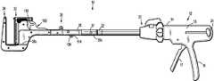
- FIG. 1is a side view of one embodiment of the presently disclosed surgical stapling device including a loading unit;
- FIG. 2is a side view of the surgical stapling device shown in FIG. 1 illustrating the loading unit de-coupled from the handle assembly;
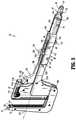
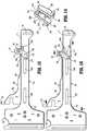
- FIG. 3is a perspective view of the loading unit shown in FIG. 1 ;
- FIG. 4is a perspective view of the loading unit shown in FIG. 3 with a portion of a frame of the loading unit cutaway;
- FIG. 5is a perspective view with parts separated of the loading unit shown in FIG. 3 ;
- FIG. 6is an enlarged view of the indicated area of detail shown in FIG. 5 illustrating a cartridge assembly of the loading unit
- FIG. 7is a perspective view, with parts separated, of a cartridge assembly including a cartridge, an alignment pin, a staple pusher assembly, and a plurality of staples;
- FIG. 8is a perspective view of the loading unit of FIG. 3 with the cartridge assembly of FIG. 6 separated;
- FIG. 9is an enlarged view of the indicated area of detail shown in FIG. 5 illustrating a first pivoting member
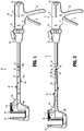
- FIG. 10is a side view of the loading unit of FIG. 3 with parts removed to illustrate a clamping plate assembly in a retracted position;
- FIG. 11is a side view of the loading unit of FIG. 3 with parts removed to illustrate the clamping plate assembly in a partially advanced position;
- FIG. 12is a side view of the loading unit of FIG. 3 with parts removed to illustrate the clamping plate assembly in a fully advanced position;
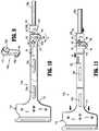
- FIG. 13is an enlarged view of the indicated area of detail shown in FIG. 12 ;
- FIG. 14is an enlarged view of the indicated area of detail shown in FIG. 5 illustrating a second pivoting member
- FIG. 15is a side view of the loading unit of FIG. 3 with parts removed to illustrate a holder in a retracted position relative to the clamping plate assembly;
- FIG. 16is a side view of the loading unit of FIG. 3 with parts removed to illustrate the holder in a partially advanced position relative to the clamping plate assembly;
- FIG. 17is a side view of the loading unit of FIG. 3 with parts removed to illustrate the holder in a fully advanced position relative to the clamping plate assembly;
- FIG. 18is an enlarged view of the indicated area of detail shown in FIG. 17 ;
- FIG. 19is a cross-sectional view taken along section line 19 - 19 of FIG. 8 ;
- FIG. 20is a perspective view of the loading unit of FIG. 3 with parts removed;
- FIG. 21is a perspective view of the loading unit of FIG. 20 with the holder removed;
- FIG. 22is an enlarged view of the loading unit of FIG. 21 with the anvil and the cartridge assembly removed;
- FIG. 23is an enlarged, cross-sectional view taken along section line 23 - 23 of FIG. 20 with the clamping plate assembly, the holder, and the stapling plate in a retracted position;
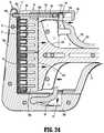
- FIG. 24illustrates the distal end of the loading unit shown in FIG. 23 with the clamping plate assembly and the holder in a fully advanced position to clamp and retain tissue, and the stapling plate in a partially advanced position;
- FIG. 25illustrates the distal end of the loading unit shown in FIG. 23 with the stapling plate in a fully advanced position to effect stapling of tissue.
- distalrefers to that portion of the instrument, which is farthest from a clinician
- proximalrefers to that portion of the instrument, which is closest to the clinician
- clinicianrefers to medical staff including doctors, nurses and support personnel.
- Surgical stapling device 10includes a handle assembly 12 , an adapter assembly 20 coupled to a distal end 14 of the handle assembly 12 , and a surgical loading unit 30 coupled to a distal end 22 of the adapter assembly 20 .
- the handle assembly 12includes a body 15 having a stationary handle 16 and a pivotable trigger 17 .
- the trigger 17is operatively coupled to a drive shaft 23 such that actuation of the trigger 17 longitudinally translates the drive shaft 23 .
- a manual engagement member or thumb button 24is slidably positioned on each side of the body 15 .
- the thumb buttons 24are operatively associated with the drive shaft 23 and can be pulled proximally by a clinician to retract the drive shaft 23 within the adapter assembly 20 .
- the loading unit 30is configured to clamp and staple tissue disposed between the cartridge assembly 32 and the anvil assembly 34 .
- the loading unit 30is selectively connectable to the distal end 22 of the adapter assembly 20 .
- the loading unit 30may be selectively connectable directly to an electromechanical handle assembly, a surgical robotic system, or any other suitable actuation mechanism.
- the loading unit 30includes a frame 36 having a proximal end 38 a and a distal end 38 b .
- the frame 36is removably coupled to the adapter assembly 20 via a coupling member 40 .
- the coupling member 40has a proximal end 40 a and a distal end 40 b .
- the proximal end 40 ais configured to be removably coupled to the distal end 22 of the adapter assembly 20 via a mating engagement between bosses 42 of the coupling member 40 and an engagement structure (not shown) formed on the distal end 22 of the adapter assembly 20 .
- the distal end 40 b of the coupling member 40includes a pair of bosses 43 , which are received within correspondingly shaped holes 37 formed in the proximal end 38 a of the frame 36 to secure the coupling member 40 to the frame 36 .
- the frame 36has a first side 44 a and a second side 44 b spaced from first side 44 a .
- the first and second sides 44 a , 44 b , respectively, of the frame 36define a longitudinal channel 46 ( FIG. 3 ) that receives various moving components of the loading unit 30 , as will be described in detail below.
- the distal end 38 b of the frame 36has a hooked configuration and extends perpendicularly relative to a longitudinal axis X ( FIG. 3 ) of the frame 36 .
- the distal end 38 b of the frame 36supports the anvil assembly 34 and guides movement of the cartridge assembly 32 in relation to the anvil assembly 34 to orient the anvil assembly 34 in a side-by-side orientation with the cartridge assembly 32 when the cartridge assembly is in an advanced position.
- An intermediary portion 45 of the frame 36defines a first opening or pivot hole 48 in each side frame 44 a , 44 b that receives a first pivoting member 140 .
- the intermediary portion 45also defines a second opening or pivot hole 50 in each side frame 44 a , 44 b that receives a second pivoting member 200 , as will be described in greater detail below.
- the anvil assembly 34includes an anvil 52 supported on the distal end 38 b of the frame 36 .
- the anvil 52defines a plurality of staple pockets 54 formed in the surface of the anvil 52 which are configured to form staples ejected from the cartridge assembly 32 .
- the anvil 52defines a bore 56 configured for passage of an alignment pin 96 , as will be described in further detail below.
- the anvil assembly 34further includes a stiffener plate 58 , a spacer plate 66 , and a t-track 70 .
- the stiffener plate 58has a vertical portion 58 a and a horizontal portion 58 b .
- the vertical portion 58 a of the stiffener plate 58is disposed within a channel 52 a of the anvil 52 and defines a notch 58 c .
- the notch 58 cis in alignment with the bore 56 of the anvil 52 and is configured to receive a distal end 96 a of the alignment pin 96 as will be discussed in further detail below.
- the horizontal portion 58 b of the stiffener plate 58defines a cutout 60 that is dimensioned to receive an interlock member 64 .
- the vertical portion 58 a of the stiffener plate 58is positioned between a vertical portion 47 a , 48 b of each respective frame side 44 a , 44 b.
- the spacer plate 66includes a pair of legs 66 a , 66 b ( FIG. 5 ) positioned on opposite sides of the stiffener plate 58 within the channel 52 a of the anvil 52 between the stiffener plate 58 and the anvil 52 .
- the anvil assembly 34includes a cap 68 that is positioned over an upper end of the anvil 52 , stiffener plate 58 and spacer plate 66 to provide a smooth surface that is less likely to snag tissue during use.
- the t-track 70 of the anvil assembly 34defines a channel 72 that receives the horizontal portion 58 b of the stiffener plate 58 .
- the t-track 70is positioned about the cutout 60 in the horizontal portion 58 b to define a cavity in which the interlock 64 is positioned.
- the components of the anvil assembly 34are secured to the frame sides 44 a , 44 b using rivets 73 .
- other fastening membersmay be used to secure the components of the anvil assembly 34 to the frame sides 44 a , 44 b including screws, pins, welding, etc.
- the components of the anvil assembly 34are formed of stainless steel.
- other materials, including metals, having requisite strength requirementscan be used to form some or all of the components of the anvil assembly 34 .
- the cartridge assembly 32is movable along an axis parallel to the longitudinal axis of the loading unit 30 from a position spaced from the anvil assembly 34 to a position in close approximation with the anvil assembly 34 to clamp and staple tissue.
- the cartridge assembly 32includes a cartridge 80 , a pusher assembly 90 , a plurality of staples 91 , and an alignment pin 96 .
- the cartridge 80has a first or vertical portion 80 a and a second or horizontal portion 80 b extending perpendicularly from the first portion 80 a .
- the first portion 80 ahas an elongate slot 82 defined in each opposing side of the cartridge 80 .
- Each elongate slot 82is configured to receive elongate projections 128 formed on a respective clamping plate 116 of the clamping plate assembly 110 ( FIG. 8 ) to frictionally secure the cartridge assembly 32 to the clamping plate assembly 110 .
- the first portion 80 a of cartridge 80has a distally-oriented, tissue engaging surface 84 that defines an array of staple receiving slots 86 and a proximally facing cavity 88 that communicates with the staple receiving slots 86 .
- the staple pusher assembly 90includes a plurality of independently movable staple pushing members 90 a , 90 b movably disposed within the cavity 88 of the first portion 80 a .
- Each pushing member 90 a , 90 bincludes a plurality of fingers 92 , which are slidably received within respective staple receiving slots 86 .
- the fingers 92are positioned proximally of the staples 91 within the slots 86 , such that advancement of the fingers 92 within the slots 86 effects ejection of the staples 91 from the slots 86 .
- the staple pusher assembly 90includes two pusher members 90 a , 90 b that form the pusher assembly 90 .
- the pusher assembly 90may be modified to include one or more pusher members.
- the cartridge assembly 32can include a single pusher member or three independently movable pusher members.
- the second or horizontal portion 80 b of the cartridge 80extends parallel to a longitudinal axis “X” defined by the frame 36 ( FIG. 3 ) and defines a guide channel 94 ( FIG. 7 ).
- the second portion 80 bsupports the alignment pin 96 , a channel cover 98 , and a spring 100 .
- the alignment pin 96is slidably supported in the guide channel 94 and has a proximal end 96 a and a distal end 96 b .
- the channel cover 98is connected to a proximal end 83 of the second portion 80 b of the cartridge 80 to close the guide channel 94 .
- the spring 100is disposed within the guide channel 94 between a distal end of the horizontal portion 80 b of the cartridge 80 and the proximal end 96 a of the alignment pin 96 to resiliently bias the alignment pin 96 to a retracted position within the guide channel 94 .
- the proximal end 96 a of the alignment pin 96defines an orifice 102 .
- the orifice 102is configured to receive an abutment member 191 of an alignment pin holder 180 ( FIG. 23 ) such that advancement of the holder 180 effects advancement of the alignment pin 96 , as described in detail below.
- the distally-oriented face 84 of the cartridge 80defines a bore 104 ( FIG. 6 ) that is coaxial and in communication with the guide channel 94 .
- the bore 104is dimensioned to receive the distal end 96 b of the alignment pin 96 to allow the alignment pin 96 to extend from within the guide channel 94 of the cartridge 80 , through the anvil bore 56 ( FIGS. 24 and 25 ), and into the notch 58 c formed in the stiffener plate 58 of the anvil assembly 34 , as will be discussed in further detail below.
- the loading unit 30 of the surgical stapling device 10includes three mechanisms including the clamping plate assembly 110 , the alignment pin holder 180 , and a stapling plate 220 .
- the clamping plate assembly 110operates to approximate the cartridge assembly 32 and the anvil assembly 34 ;
- the holder 180operates to move the alignment pin 96 between retracted and advanced positions;
- the stapling plate 220operates to move the staple pushing members 90 a , 90 b to eject staples 91 from the cartridge 80 into tissue.
- the clamping plate assembly 110 , the alignment pin holder 180 , and the stapling plate 220are movably supported between frame sides 44 a and 44 b of the frame 36 between retracted and advanced positions in response to movement of a pusher 105 .
- the pusher 105is operatively coupled to the drive shaft 23 of the stapling device 10 when the loading unit 30 is coupled to the stapling device 10 such that movement of the trigger 17 of the handle assembly 12 of the stapling device 10 effects movement of the pusher 105 and, thus, effects operation of the clamping plate assembly 110 , the holder 180 , and the stapling plate 220 , as will be discussed in further detail below.
- the pusher 105is slidably supported within the coupling member 40 of the loading unit 100 between retracted and advanced positions.
- the pusher 105has a proximal end 105 a and a distal end 105 b .
- the proximal end 105 a of the pusher 105is configured to receive and operatively engage a distal end of the drive shaft 23 of the stapling device 10 ( FIG. 2 ) such that longitudinal movement of the drive shaft 23 , in response to actuation of the trigger 17 of the handle assembly 12 , results in a corresponding longitudinal motion of the pusher 105 .
- the distal end 105 b of the pusher 105is operatively associated with the clamping plate assembly 110 , the alignment pin holder 180 , and the stapling plate 220 such that advancement of the pusher 105 actuates the clamping plate assembly 110 , the alignment pin holder 180 , and the stapling plate 220 as discussed below.
- the distal end 105 b of the pusher 105defines a bore 106 a ( FIG. 5 ) that receives a pin 106 .
- the pin 106extends through the bore 106 a and is received within a hole 223 defined in the stapling plate 220 to fixedly connect the pusher 105 with the stapling plate 220 . As such, advancement of the pusher 105 causes corresponding advancement of the stapling plate 220 .
- the distal end 105 b of the pusher 105also defines a slot 107 .
- a pivoting member 140is provided to couple the pusher 105 to the clamping plate assembly 110 .
- the pivoting member 140has a first end 144 adapted to be coupled to the pusher 105 and a second end adapted to be coupled to the clamping plate assembly 110 such that advancement of the pusher 105 also effects advancement of the clamping plate assembly 110 , as described in detail below.
- the clamping plate assembly 110includes clamp slide members 110 a , 110 b .
- Each clamp slide member 110 a , 110 bhas a distal end 112 , a proximal end 114 , and an elongated body 116 extending therebetween.
- the distal end 112 of each clamp slide member 110 a , 110 bincludes a head portion 118 .
- Each head portion 118has a plurality of openings 120 configured to receive a fastening member 122 for securing clamp slide members 110 a , 110 b together in spaced relation to each other.
- clamp slide members 110 a , 110 bare spaced from each other to define an elongated channel 124 , which slidably receives the alignment pin holder 180 and the stapling plate 220 and releasably supports the cartridge assembly 32 .
- the head portions 118 of the clamp slide members 110 a , 110 bdefine a cartridge support receptacle 126 that is configured to releasably support the cartridge assembly 32 .
- each clamp slide member 110 a , 110 bincludes an elongate projection 128 that extends into the cartridge support receptacle 126 .
- each of the elongate slots 82 of the cartridge 80receive a respective elongate projection 128 of a clamp slide member 110 a , 110 b to retain the cartridge assembly 32 within the cartridge support receptacle 126 .
- each clamp slide member 110 a , 110 bincludes a pair of elongated guide slots 130 a , 130 b ( FIG. 5 ).
- the guide slots 130 a , 130 bslidably receive pins 132 a , 132 b , respectively, which extend between and interconnect the frame sides 44 a , 44 b .
- the pins 132 a , 132 bare positioned in the guide slots 130 a , 130 b to maintain alignment of the clamp slide members 110 a , 110 b between the frame sides 44 a , 44 b during movement of the clamp slide members 110 a , 110 b between the advanced and retracted positions and to limit the extent of longitudinal movement of the clamp slide members 110 a , 110 b . More specifically, engagement of the pins 132 a , 132 b with the proximal ends of the guide slots 130 a , 130 b , respectively, prevents further distal movement clamping plate assembly 110 in relation to the frame 36 and defines the fully advanced position of the clamping plate assembly 110 .
- each clamp slide member 110 a , 110 bdefines first and second slots 134 and 136 , respectively.
- the first slot 134is a vertical slot and the second slot 136 is an L-shaped slot.
- the vertical slot 134is disposed proximally of the L-shaped slot 136 and is in alignment with a portion of the slot 107 of the pusher 105 .
- the pivoting member 140includes a first rocker or cam member 140 a which interconnects the frame side 44 a to the clamp slide member 110 a .
- the pivoting member 140can also include a second rocker or cam member 140 b to interconnect the frame side 44 b to the clamp slide member 110 b .
- Each cam member 140 a , 140 bhas a first end 142 and a second end 144 .
- the first end 142 of the first cam member 140 aincludes a protrusion 142 a that is pivotably received within the pivot hole 48 defined in the left frame side 44 a and the first end 142 of the second cam member 140 b is pivotably received within the pivot hole 50 defined within the right frame side 44 b .
- the second end 144 of each cam member 140 a , 140 bdefines a protrusion 144 a that extends through the vertical slots 134 of a respective clamp slide member 110 a , 110 b and the slot 107 of the pusher 105 to operatively couple the clamping plate assembly 110 with the pusher 105 .
- the cam members 140 a and 140 bare pivoted about the protrusion 142 a formed at the first ends 142 of the cam members 140 a and 140 b .
- engagement of protrusion 144 a with clamp slide members 110 a , 110 bcauses movement of the clamp slide members 110 a , 110 b , as will be discussed in detail below.
- the slot 107 of the pusher 105has a vertical portion 107 a and a horizontal portion 107 b that communicate with one another.
- the protrusion 144 b at the second end 144 of each cam member 140 a , 140 bis slidably captured within the respective vertical slots 134 of the clamp slide members 110 a , 110 b of the clamping plate assembly 110 and the vertical portion 107 a of the slot 107 of the pusher 105 .
- the vertical slots 134 of the clamping plate assembly 110also allow the protrusion 144 a formed at the second end 144 of each cam member 140 a , 140 b to ride from a bottom end of each respective vertical slot 134 towards a top end of each of the vertical slots 134 as the cam members 140 a , 140 b rotate.
- continued rotation of the first pivoting member 140via continued advancement of the pusher 105 , moves the protrusion 144 a on the second ends 144 of the cam members 140 a , 140 b to the top ends of the vertical slots 134 to a position adjacent the horizontal portion 107 b of the slot 107 of the pusher 105 .
- further advancement of the pusher 105will cause the protrusions 144 a to move within the horizontal portions 107 b of the slots 107 of the pusher 105 such that the cam members 140 a , 140 b will cease to rotate.
- continued advancement of the pusher 105will no longer effect advancement of the clamping plate assembly 110 .
- the alignment pin holder 180 of the loading unit 30is configured to move the alignment pin 96 between retraced and advanced positions.
- the holder 180defines a channel 188 along its length dimensioned to slidably receive the stapling plate 220 and includes a distal end 182 , a proximal end 184 , and a body 186 disposed between the distal and proximal ends 182 , 184 .
- the distal end 182includes a vertically extending abutment member 191 that is configured to engage the proximal end 96 a ( FIG.
- the body 186 of the holder 180includes a pair of elongated slots 192 a and 192 b .
- the pins 132 a , 132 bextend through the slots 192 a and 192 b , respectively, to support the holder 180 for linear movement relative to the frame 36 and guide the holder 180 during movement of the holder 180 between the advanced and retracted positions.
- the proximal end 184 of the holder 180includes a capture member, such as, for example, a C-clip 194 , that defines a vertical slot 196 .
- the vertical slot 196 of the C-clip 194 of the holder 180is configured to releasably receive a bar 214 of the second pivoting member 200 .
- the L-shaped slots 136 of the clamp slide members 110 a , 110 breceive a cam member 212 of the second pivoting member 200 , such that longitudinal movement of the clamp slide members 110 a , 110 b effect longitudinal movement of the holder 180 , as will be described in detail below.
- the second pivoting member 200includes a pair of spaced apart sidewalls 202 a , 202 b each having a triangular configuration.
- sidewalls 202 a , 202 bmay assume a variety of configurations, such as, for example, oblong, tapered, squared, polygonal, kidney-bean shaped, or the like.
- Each sidewall 202 a , 202 b of the second pivoting member 200has a first end 204 , a second end 206 , and an intermediate portion 208 disposed between the first and second ends 204 , 206 .
- the second end 206has a pair of protrusions 210 extending laterally, outwardly from the sidewalls 202 a , 202 b .
- the protrusions 210are configured to be pivotably received within the pivot holes 50 defined in the frame sides 44 a , 44 b to rotatably secure the second pivoting member 200 between frame sides 44 a , 44 b of the frame 36 .
- the intermediate portion 208 of each sidewall 202 a , 202 bincludes an inwardly extending cam member 212 configured to be received within the L-shaped slots 136 formed in the proximal end 114 of respective clamp slide members 110 a , 110 a of the clamping plate assembly 110 .
- the first end 204 of the second pivoting member 200has a link or bar 214 interconnecting the sidewalls 202 a , 202 b of the second pivoting member 200 .
- the bar 214is radially offset or spaced from the cam members 212 of the second pivoting member 200 . As mentioned above, the bar 214 is releasably received within the vertical slot 196 of the C-clip 194 of the holder 180 .
- advancement of the pusher 105effects advancement of the clamp slide members 110 a , 110 b , as described above.
- advancement of the clamp slide members 110 a , 110 beffects rotation of the second pivoting member 200 and rotation of the second pivoting member 200 effects movement of the holder 180 between retracted and advanced positions.
- the L-shaped slot 136 of each clamp slide member 110 a , 110 b of the clamping plate assembly 110includes a vertical portion 136 a and a horizontal portion 136 b .
- the cam members 212 of the second pivoting member 200are received within the vertical portion 136 a of the slot 136 of each of the clamp slide members 110 a 110 b .
- walls that define the vertical portion 136 a of the L-shaped slot 136 of the clamping plate assembly 110engage the cam members 212 of the second pivoting member 200 to pivot the second pivoting member 200 , relative to the frame 36 , about the second end 206 of the second pivoting member 200 .
- the bar 214 of the second pivoting member 200engages the C-clip 194 of the holder 180 to urge the holder 180 in a distal direction, indicated by arrow “C” in FIG. 16 .
- the bar 214rides within the vertical slot 196 defined in the C-clip 194 as the bar 214 traverses an arced pathway.
- the bar 214 of the second pivoting member 200is radially distanced further from the protrusions 210 (i.e., the pivot point) of the second pivoting member 200 than the cam members 212 , pivotal movement of the second pivoting member 200 effects movement of the bar 214 moves along its arced pathway at a greater rotational velocity than the cam members 212 move along their arced pathways.
- the holder 180is caused to advance distally relative to the clamping plate assembly 110 (i.e., the holder 180 advances relative to the frame 36 faster than the clamping plate assembly 110 ).
- continued rotation of the second pivoting member 200in response to continued advancement of the clamping plate assembly 110 , moves the cam members 212 of the second pivoting member 200 to the top end of the vertical portion 136 a of the L-shaped slots 136 to a position adjacent the horizontal portion 136 b of the L-shaped slots. In this position, further rotation of the second pivoting member 200 will cause the cam members 212 to move within the horizontal portion 136 b of the L-shaped slots 136 of the clamping plate assembly 110 such that the second pivoting member 200 will cease to rotate.
- the stapling plate 220 of the loading unit 100is configured to eject the staples 91 from the cartridge assembly 32 .
- the channel 188( FIG. 8 ) defined longitudinally through the holder 180 slidably receives the stapling plate 220 .
- the stapling plate 220includes a proximal end 222 , a distal end 224 , and a body 226 disposed between the proximal and distal ends 222 , 224 .
- the proximal end 222 of the stapling plate 220is fixedly disposed within the distal end 105 b of the pusher 105 and has an opening 223 configured for receipt of the rivet or pin 106 of the pusher 105 to couple the proximal end 222 of the stapling plate 220 to the pusher 105 .
- longitudinal movement of the pusher 105results in corresponding longitudinal movement of the stapling plate 220 .
- the stapling plate 220may be connected to the pusher 105 via various fastening engagements, such, as, for example, those alternatives described herein.
- the distal end 224 of the stapling plate 220includes an engagement head 228 configured to engage the staple pushing members 90 a , 90 b ( FIG. 7 ).
- the body 126 of the stapling plate 220includes a pair of elongated slots 230 a , 230 b dimensioned to slidably receive the pins 132 a , 132 b ( FIG. 4 ).
- the slots 230 a , 230 b in the stapling plate 220are longer than the slots 130 a , 130 b formed in the clamp slide members 110 a , 110 b , respectively.
- the increased length of the slots 230 a , 230 bpermits the stapling plate 220 to be advanced distally, independently of the clamp slides 110 a , 110 b , through the cartridge assembly 32 to eject the staples 91 from the cartridge assembly 32 .
- the stapling plate 220defines a forward elongated slot 234 .
- the rivets 235that extend between clamp slide members 110 a , 110 b to secure the clamp slide members 110 a , 110 b in spaced relation to each other extend through the slot 234 .
- the rivets 235engage the forward end of the slot 234 of the stapling plate 220 to concurrently advance the stapling plate 220 with the clamp slide members 110 a , 110 b .
- the slot 234is of a length to allow the stapling plate 220 to continue to advance distally relative to the clamping plate assembly 110 upon the clamping plate assembly 110 reaching its fully advanced position.
- further advancement of the stapling plate 220is effected by the pusher 105 .
- FIG. 23illustrates the distal end of the surgical stapling device 10 prior to use.
- the cartridge assembly 32is inserted within the receptacle 126 defined between the clamp slide members 110 a , 110 b to engage and depress the interlock 64 as known in the art.
- the interlock 64With the interlock 64 depressed into the cutout 60 , the interlock 64 no longer blocks movement of the stapling plate 220 .
- the trigger 17FIGS. 1 and 2
- the clamping plate assembly 110 , the holder 180 , and the stapling plate 220are in their respective retracted positions.
- the associated cartridge 80 , alignment pin 96 , and staple pusher members 90 a , 90 b , respectively,are also in a retracted or non-actuated position.
- a cliniciancould optionally manually advance the holder 180 and, in turn, the alignment pin 96 by pushing thumb button(s) 24 ( FIG. 1 ) distally. This operation would disengage the bar 214 of the second pivoting member 200 from the C-clip 194 of the holder 180 and advance the holder 180 distally independently of the clamp slide assembly 110 .
- FIG. 24illustrates the surgical stapling device 10 after an initial approximation stroke of the trigger 17 .
- the drive shaft 23 ( FIG. 1 ) of the adapter assembly 20advances and, in turn, advances the pusher 105 .
- Advancement of the pusher 105effects advancement of the clamping plate assembly 110 via the first pivoting member 140 in the manner described above. Since the cartridge assembly 32 is connected to the head portion 118 of the clamping plate assembly 110 (see FIG.
- advancement of the clamping plate assembly 110also advances the cartridge assembly 32 including all of its components (e.g., the cartridge 80 , the pusher assembly 90 , and the alignment pin 96 ) toward the anvil assembly 34 to clamp tissue “T” disposed between the cartridge assembly 32 and the anvil assembly 34 .
- the stapling plate 220moves with the clamping plate assembly 110 such that the associated staple pusher members 90 a , 90 b do not move relative to the cartridge 80 .
- the holder 180advances relative to the clamping plate assembly 110 via the second pivoting member 200 in the manner described above. Movement of the holder 180 from the retracted position to the advanced position urges the abutment member 191 of the holder 180 through the guide channel 94 of the cartridge 80 to advance the alignment pin 96 into the notch 58 c of the anvil assembly 34 prior to the cartridge assembly 32 and the anvil assembly 34 being fully approximated. With the alignment pin 96 disposed in the notch 58 c of the anvil assembly 34 , tissue “T” disposed between the cartridge assembly 32 and the anvil assembly 34 is prevented from escaping the space between the cartridge assembly 32 and the anvil assembly 34 .
- FIG. 25illustrates the surgical stapling device 10 after the trigger 17 has been moved through the firing stroke to the fully actuated position.
- continued actuation of the trigger 17will cease to result in advancement of the clamping plate assembly 110 and its associated cartridge 80 due to the first pivoting member 140 no longer being pivoted by the pusher 105 , as described in detail above with reference to FIGS. 12 and 13 .
- Operating the firing strokewill continue to effect advancement of the stapling plate 220 due to the direct connection between the constantly moving pusher 105 and the stapling plate 220 , as described in detail above.
- the stapling plate 220urges the staple pusher members 90 a , 90 b distally through the stationary cartridge 80 to eject the staples 91 from the cartridge assembly 32 into the tissue “T.”
- This sequence of advancement of the cartridge 80 , the alignment pin 96 , and the staple pusher members 90 a , 90 bis effected by one continuous actuation of the trigger 17 due to the operative association of the pusher 105 with each of the clamping plate assembly 110 , the holder 180 , and the stapling plate 220 .
- the interlock 64is normally urged by the pusher assembly 90 to a position located within the recess 60 . After the cartridge assembly 32 has been fired, the pusher assembly 90 is no longer positioned to bias the interlock 64 into the recess 60 . Until a new cartridge is inserted into the surgical stapling device 10 , the interlock 64 will remain extended from the recess 60 to prevent the stapling plate 220 from being advanced distally.
- the trigger 17After actuating the trigger, the trigger 17 will bias back toward the un-actuated position. As the trigger 17 returns to the un-actuated position, the clamping plate assembly 110 and its associated cartridge 80 , the holder 180 and its associated alignment pin 96 , and the stapling plate 220 and its associated staple pushing members 90 a , 90 b , all revert to their respective retracted positions via a similar sequence described above with respect to their respective advancements. In particular, with respect to FIG. 25 , as the pusher 105 is moved from its advanced to its retracted position, in response to a decompressing of the trigger 17 , the stapling plate 220 moves proximally due to being directly connected to the pusher 105 .
- a proximally-oriented surface 229 of the engagement head 228 of the stapling plateengages a pin 231 extending laterally from the clamping plate assembly 110 to urge the clamping plate assembly 110 proximally.
- Proximal movement of the clamping plate assembly 110effects proximal movement of the cartridge assembly 32 , which is coupled to the clamping plate assembly 110 .
- continued proximal movement of the clamping plate assembly 110causes the holder 180 to move proximally to its retracted position once the cam members 212 of the second pivoting member 200 move from the horizontal portion 136 b of the L-shaped slot 136 of the clamping plate assembly 110 to the vertical portion 136 a of the L-shaped slot 136 of the clamping plate assembly 110 .
- continued proximal movement of the clamping plate assembly 110also moves the second ends 144 of the first pivoting member 140 from the horizontal portion 107 a of the slot 107 of the pusher 105 to the vertical portion 107 a of the slot 107 of the pusher 105 to position the clamping plate assembly 110 in the retracted position.
- the components of the surgical stapling devicecan be formed of any material suitable for surgical use and having the required strength characteristics. Therefore, the above description should not be construed as limiting, but merely as exemplifications of preferred embodiments. Those skilled in the art will envision other modifications within the scope and spirit of the claims appended hereto.
Landscapes
- Health & Medical Sciences (AREA)
- Life Sciences & Earth Sciences (AREA)
- Surgery (AREA)
- Heart & Thoracic Surgery (AREA)
- Engineering & Computer Science (AREA)
- Biomedical Technology (AREA)
- Nuclear Medicine, Radiotherapy & Molecular Imaging (AREA)
- Medical Informatics (AREA)
- Molecular Biology (AREA)
- Animal Behavior & Ethology (AREA)
- General Health & Medical Sciences (AREA)
- Public Health (AREA)
- Veterinary Medicine (AREA)
- Surgical Instruments (AREA)
Abstract
Description
Claims (22)
Applications Claiming Priority (1)
| Application Number | Priority Date | Filing Date | Title |
|---|---|---|---|
| PCT/CN2014/094918WO2016101206A1 (en) | 2014-12-25 | 2014-12-25 | Surgical stapling devices |
Publications (2)
| Publication Number | Publication Date |
|---|---|
| US20170340324A1 US20170340324A1 (en) | 2017-11-30 |
| US10702269B2true US10702269B2 (en) | 2020-07-07 |
Family
ID=56148937
Family Applications (1)
| Application Number | Title | Priority Date | Filing Date |
|---|---|---|---|
| US15/535,076Active2035-11-03US10702269B2 (en) | 2014-12-25 | 2014-12-25 | Surgical stapling devices |
Country Status (5)
| Country | Link |
|---|---|
| US (1) | US10702269B2 (en) |
| EP (1) | EP3236862A1 (en) |
| JP (1) | JP6484341B2 (en) |
| CN (1) | CN107106169B (en) |
| WO (1) | WO2016101206A1 (en) |
Families Citing this family (7)
| Publication number | Priority date | Publication date | Assignee | Title |
|---|---|---|---|---|
| US10945730B2 (en)* | 2018-06-25 | 2021-03-16 | Covidien Lp | Stapling device with selectively advanceable alignment pin |
| CA3154603A1 (en)* | 2019-09-16 | 2021-03-25 | Covidien Lp | Surgical stapling device with cartridge assembly retainer |
| WO2021120046A1 (en)* | 2019-12-18 | 2021-06-24 | Covidien Lp | Surgical stapling device with shipping cap |
| EP4099917A4 (en)* | 2020-02-03 | 2024-04-10 | Covidien LP | SURGICAL STAPLING INSTRUMENT WITH CURVED END EFFECTOR ASSEMBLY |
| WO2021155483A1 (en)* | 2020-02-03 | 2021-08-12 | Covidien Lp | Tissue guide for curved end effectors |
| US11744584B2 (en)* | 2020-06-09 | 2023-09-05 | Covidien Lp | Alignment pin assembly for surgical stapler |
| US12268390B2 (en) | 2021-07-19 | 2025-04-08 | Covidien Lp | Stapling device with replaceable cartridge module |
Citations (151)
| Publication number | Priority date | Publication date | Assignee | Title |
|---|---|---|---|---|
| US1158111A (en) | 1914-10-07 | 1915-10-26 | Edward C Ahlheim | Rolling-pin. |
| US2891250A (en) | 1956-10-15 | 1959-06-23 | Hirata Yasuhiro | Bronchus seaming instrument |
| US3080564A (en) | 1959-09-10 | 1963-03-12 | Strekopitov Alexey Alexeevich | Instrument for stitching hollow organs |
| US3252643A (en) | 1962-12-24 | 1966-05-24 | Strekopytov Alexey Alexcevich | Instrument for suturing living tissue |
| US3269630A (en) | 1964-04-30 | 1966-08-30 | Fleischer Harry | Stapling instrument |
| US3275211A (en) | 1965-05-10 | 1966-09-27 | United States Surgical Corp | Surgical stapler with replaceable cartridge |
| US3315863A (en) | 1965-07-06 | 1967-04-25 | United States Surgical Corp | Medical instrument |
| US3494533A (en) | 1966-10-10 | 1970-02-10 | United States Surgical Corp | Surgical stapler for stitching body organs |
| US3589589A (en) | 1967-09-19 | 1971-06-29 | Ernest Mikhailovich Akopov | Surgical instrument for stitching tissues by means of staples |
| US3692224A (en) | 1970-10-14 | 1972-09-19 | Georgy Vasilievich Astafiev | Surgical apparatus for suturing tissue with staples |
| US3795034A (en) | 1971-05-03 | 1974-03-05 | S Eizenshteina | Surgical instrument for suturing tissues and organs with metal staples |
| US3822818A (en) | 1973-02-20 | 1974-07-09 | A Strekopytov | Surgical instrument for joining osseous tissues by staples |
| US3935981A (en) | 1973-07-31 | 1976-02-03 | Ernest Mikhailovich Akopov | Surgical apparatus for suturing organs and tissues with metal staples |
| US3949923A (en) | 1973-07-26 | 1976-04-13 | Ernest Mikhailovich Akopov | Surgical suturing instrument |
| US4047654A (en) | 1976-06-23 | 1977-09-13 | Alfredo Alvarado | Surgical stapler |
| US4216891A (en) | 1979-02-12 | 1980-08-12 | Behlke Harold O | Surgical stapler |
| US4244372A (en) | 1978-03-31 | 1981-01-13 | Kapitanov Nikolai N | Surgical instrument for suturing organs |
| US4296881A (en) | 1980-04-03 | 1981-10-27 | Sukoo Lee | Surgical stapler using cartridge |
| US4305539A (en) | 1979-03-26 | 1981-12-15 | Korolkov Ivan A | Surgical suturing instrument for application of a staple suture |
| US4354628A (en) | 1980-09-29 | 1982-10-19 | United States Surgical Corporation | Surgical stapler apparatus having pivotally related staple holder and anvil |
| US4378901A (en) | 1980-05-22 | 1983-04-05 | Akopov Ernest M | Apparatus for applying a staple suture |
| US4383634A (en) | 1981-05-26 | 1983-05-17 | United States Surgical Corporation | Surgical stapler apparatus with pivotally mounted actuator assemblies |
| US4402444A (en) | 1981-04-20 | 1983-09-06 | United States Surgical Corporation | Surgical stapling instrument with automatic frame reinforcement |
| US4415112A (en) | 1981-10-27 | 1983-11-15 | United States Surgical Corporation | Surgical stapling assembly having resiliently mounted anvil |
| USD273513S (en) | 1983-06-10 | 1984-04-17 | Senco Products, Inc. | Linear surgical stapling instrument |
| US4442964A (en) | 1981-12-07 | 1984-04-17 | Senco Products, Inc. | Pressure sensitive and working-gap controlled surgical stapling instrument |
| US4470533A (en) | 1982-08-13 | 1984-09-11 | Ethicon, Inc. | Surgical instrument for suturing tissues and organs |
| US4475679A (en) | 1981-08-07 | 1984-10-09 | Fleury Jr George J | Multi-staple cartridge for surgical staplers |
| US4485811A (en) | 1980-02-08 | 1984-12-04 | Vsesojuzny Nauchny Tsentr Khirurgii | Resection apparatus |
| US4506671A (en) | 1983-03-30 | 1985-03-26 | United States Surgical Corporation | Apparatus for applying two-part surgical fasteners |
| US4506670A (en) | 1983-03-30 | 1985-03-26 | United States Surgical Corporation | Two-part surgical fastener applying apparatus with frangible member |
| US4508253A (en) | 1983-10-04 | 1985-04-02 | United States Surgical Corporation | Surgical fastener applying apparatus |
| US4522327A (en) | 1983-05-18 | 1985-06-11 | United States Surgical Corporation | Surgical fastener applying apparatus |
| US4527724A (en) | 1983-06-10 | 1985-07-09 | Senmed, Inc. | Disposable linear surgical stapling instrument |
| US4530453A (en) | 1983-10-04 | 1985-07-23 | United States Surgical Corporation | Surgical fastener applying apparatus |
| US4550870A (en) | 1983-10-13 | 1985-11-05 | Alchemia Ltd. Partnership | Stapling device |
| US4566620A (en) | 1984-10-19 | 1986-01-28 | United States Surgical Corporation | Articulated surgical fastener applying apparatus |
| US4568009A (en) | 1984-01-20 | 1986-02-04 | United States Surgical Corporation | Surgical fastener applying apparatus |
| US4573622A (en) | 1984-10-19 | 1986-03-04 | United States Surgical Corporation | Surgical fastener applying apparatus with variable fastener arrays |
| US4580712A (en) | 1984-10-19 | 1986-04-08 | United States Surgical Corporation | Surgical fastener applying apparatus with progressive application of fastener |
| US4585153A (en) | 1984-07-16 | 1986-04-29 | Ethicon, Inc. | Surgical instrument for applying two-piece fasteners comprising frictionally held U-shaped staples and receivers (Case III) |
| US4589582A (en) | 1984-08-23 | 1986-05-20 | Senmed, Inc. | Cartridge and driver assembly for a surgical stapling instrument |
| US4602634A (en) | 1983-09-23 | 1986-07-29 | Ethicon, Inc. | Method and instrument for applying a fastener to a tissue using means to grasp, guide and pull the fastener through the tissue |
| US4605001A (en) | 1984-10-19 | 1986-08-12 | Senmed, Inc. | Surgical stapling instrument with dual staple height mechanism |
| US4605004A (en) | 1984-07-16 | 1986-08-12 | Ethicon, Inc. | Surgical instrument for applying fasteners said instrument including force supporting means (case IV) |
| US4606345A (en) | 1984-07-16 | 1986-08-19 | Ethicon, Inc. | Surgical instrument for applying two-piece fasteners comprising U-shaped staples and frictionally held receivers (Case II) |
| US4606344A (en) | 1984-07-16 | 1986-08-19 | Ethicon, Inc. | Surgical instrument for applying fasteners having improved gap indicating means (Case V) |
| US4607636A (en) | 1984-07-16 | 1986-08-26 | Ethicon, Inc. | Surgical instrument for applying fasteners having tissue locking means for maintaining the tissue in the instrument while applying the fasteners (case I) |
| US4612933A (en) | 1984-03-30 | 1986-09-23 | Senmed, Inc. | Multiple-load cartridge assembly for a linear surgical stapling instrument |
| US4617928A (en) | 1984-09-17 | 1986-10-21 | Alfranca Jose Maria P | Surgical instrument for practicing mechanical sutures and biopsies |
| US4632290A (en) | 1981-08-17 | 1986-12-30 | United States Surgical Corporation | Surgical stapler apparatus |
| US4665916A (en) | 1985-08-09 | 1987-05-19 | United States Surgical Corporation | Surgical stapler apparatus |
| US4684051A (en) | 1985-09-10 | 1987-08-04 | Akopov Ernest M | Surgical instrument |
| US4714187A (en) | 1986-11-26 | 1987-12-22 | United States Surgical Corporation | Reloading unit for surgical fastening instruments |
| US4715520A (en) | 1985-10-10 | 1987-12-29 | United States Surgical Corporation | Surgical fastener applying apparatus with tissue edge control |
| US4728020A (en) | 1985-08-30 | 1988-03-01 | United States Surgical Corporation | Articulated surgical fastener applying apparatus |
| US4767044A (en) | 1984-10-19 | 1988-08-30 | United States Surgical Corporation | Surgical fastener applying apparatus |
| US4788978A (en) | 1979-11-23 | 1988-12-06 | Strekopytov Alexei A | Surgical instrument for applying linear staple sutures and intersecting the tissue therebetween |
| US4802614A (en) | 1986-05-23 | 1989-02-07 | United States Surgical Corporation | Surgical stapling instrument and cartridge |
| US4805823A (en) | 1988-03-18 | 1989-02-21 | Ethicon, Inc. | Pocket configuration for internal organ staplers |
| US4819853A (en) | 1987-12-31 | 1989-04-11 | United States Surgical Corporation | Surgical fastener cartridge |
| US4848637A (en) | 1987-06-11 | 1989-07-18 | Pruitt J Crayton | Staple device for use on the mesenteries of the abdomen |
| US4881545A (en) | 1988-12-08 | 1989-11-21 | United States Surgical Corporation | Surgical fastener cartridge with improved body tissue cutting knife assembly |
| US4881544A (en) | 1988-12-19 | 1989-11-21 | United States Surgical Corporation | Surgical stapler apparatus with improved tissue shield |
| US4915100A (en) | 1988-12-19 | 1990-04-10 | United States Surgical Corporation | Surgical stapler apparatus with tissue shield |
| US4930503A (en) | 1987-06-11 | 1990-06-05 | Pruitt J Crayton | Stapling process and device for use on the mesenteries of the abdomen |
| US4938408A (en) | 1988-01-15 | 1990-07-03 | Ethicon, Inc. | Surgical stapler safety and sequencing mechanisms |
| US4941623A (en) | 1987-05-12 | 1990-07-17 | United States Surgical Corporation | Stapling process and device for use on the mesentery of the abdomen |
| US5005754A (en) | 1990-04-04 | 1991-04-09 | Ethicon, Inc. | Bladder and mandrel for use with surgical stapler |
| US5071052A (en) | 1988-09-22 | 1991-12-10 | United States Surgical Corporation | Surgical fastening apparatus with activation lockout |
| US5100042A (en) | 1990-03-05 | 1992-03-31 | United States Surgical Corporation | Surgical fastener apparatus |
| US5116349A (en) | 1990-05-23 | 1992-05-26 | United States Surgical Corporation | Surgical fastener apparatus |
| US5137198A (en) | 1991-05-16 | 1992-08-11 | Ethicon, Inc. | Fast closure device for linear surgical stapling instrument |
| US5172845A (en) | 1991-04-12 | 1992-12-22 | Tejeiro William V | Right angle articulated intestinal stapler |
| US5190203A (en) | 1990-10-05 | 1993-03-02 | United States Surgical Corporation | Controlled closure mechanism |
| US5219111A (en) | 1991-03-11 | 1993-06-15 | Ethicon, Inc. | Pneumatically actuated linear stapling device |
| US5240163A (en) | 1991-10-30 | 1993-08-31 | American Cyanamid Company | Linear surgical stapling instrument |
| US5368599A (en) | 1992-10-08 | 1994-11-29 | United States Surgical Corporation | Surgical fastening apparatus with suture array |
| US5405073A (en) | 1993-12-06 | 1995-04-11 | Ethicon, Inc. | Flexible support shaft assembly |
| US5413267A (en) | 1991-05-14 | 1995-05-09 | United States Surgical Corporation | Surgical stapler with spent cartridge sensing and lockout means |
| US5439155A (en) | 1993-10-07 | 1995-08-08 | United States Surgical Corporation | Cartridge for surgical fastener applying apparatus |
| US5452836A (en) | 1994-02-07 | 1995-09-26 | Ethicon Endo-Surgery, Inc. | Surgical stapling instrument with improved jaw closure and staple firing actuator mechanism |
| US5458279A (en) | 1991-05-14 | 1995-10-17 | Minnesota Mining And Manufacturing Company | Surgical stapler with safety feature |
| US5462215A (en) | 1991-10-18 | 1995-10-31 | United States Surgical Corporation | Locking device for an apparatus for applying surgical fasteners |
| US5464144A (en) | 1993-08-19 | 1995-11-07 | United States Surgical Corporation | Surgical apparatus with indicator |
| US5465894A (en) | 1993-12-06 | 1995-11-14 | Ethicon, Inc. | Surgical stapling instrument with articulated stapling head assembly on rotatable and flexible support shaft |
| US5470008A (en) | 1993-12-20 | 1995-11-28 | United States Surgical Corporation | Apparatus for applying surgical fasteners |
| US5470006A (en) | 1990-12-06 | 1995-11-28 | United States Surgical Corporation | Surgical fastening apparatus with locking mechanism |
| US5470009A (en) | 1990-12-06 | 1995-11-28 | United States Surgical Corporation | Surgical fastening apparatus with locking mechanism |
| US5509596A (en) | 1991-10-18 | 1996-04-23 | United States Surgical Corporation | Apparatus for applying surgical fasteners |
| US5542594A (en) | 1993-10-06 | 1996-08-06 | United States Surgical Corporation | Surgical stapling apparatus with biocompatible surgical fabric |
| US5547117A (en) | 1994-03-30 | 1996-08-20 | Ethicon Endo-Surgery | Handle actuator for surgical instrument having clamp lock and emergency release |
| US5558266A (en) | 1991-10-18 | 1996-09-24 | United States Surgical Corporation | Apparatus for applying surgical fasteners |
| US5579978A (en) | 1991-10-18 | 1996-12-03 | United States Surgical Corporation | Apparatus for applying surgical fasteners |
| US5605272A (en) | 1996-03-12 | 1997-02-25 | Ethicon Endo-Surgery, Inc. | Trigger mechanism for surgical instruments |
| US5641111A (en) | 1995-06-28 | 1997-06-24 | Ethicon Endo-Surgery, Inc. | Surgical stapling instrument with anvil cutting guide |
| US5678748A (en) | 1995-05-24 | 1997-10-21 | Vir Engineering | Surgical stapler with improved safety mechanism |
| US5697543A (en) | 1996-03-12 | 1997-12-16 | Ethicon Endo-Surgery, Inc. | Linear stapler with improved firing stroke |
| US5706998A (en) | 1995-07-17 | 1998-01-13 | United States Surgical Corporation | Surgical stapler with alignment pin locking mechanism |
| US5735445A (en) | 1995-03-07 | 1998-04-07 | United States Surgical Corporation | Surgical stapler |
| US5810240A (en) | 1996-03-15 | 1998-09-22 | United States Surgical Corporation | Surgical fastener applying device |
| US5893506A (en) | 1994-03-01 | 1999-04-13 | United States Surgical Corporation | Surgical stapler with anvil sensor and lockout |
| US6638285B2 (en) | 2001-04-16 | 2003-10-28 | Shlomo Gabbay | Biological tissue strip and system and method to seal tissue |
| US20040164123A1 (en) | 2000-10-13 | 2004-08-26 | Racenet David C. | Surgical stapling device |
| US6805273B2 (en) | 2002-11-04 | 2004-10-19 | Federico Bilotti | Surgical stapling instrument |
| CN1669534A (en) | 2003-12-30 | 2005-09-21 | 伊西康内外科公司 | Closed Disc Lock for Curved Knife Stapler |
| US20050247752A1 (en) | 2003-12-30 | 2005-11-10 | Kelly William D | Surgical stapler having an aluminum head |
| US6988650B2 (en) | 2003-12-30 | 2006-01-24 | Ethicon Endo-Surgery, Inc. | Retaining pin lever advancement mechanism for a curved cutter stapler |
| US7070083B2 (en) | 2002-04-11 | 2006-07-04 | Tyco Healthcare Group Lp | Surgical stapling apparatus including an anvil and cartridge each having cooperating mating surfaces |
| US20060163312A1 (en) | 2002-10-04 | 2006-07-27 | Viola Frank J | Angled surgical fastener apparatus |
| US7134587B2 (en) | 2003-12-30 | 2006-11-14 | Ethicon Endo-Surgery, Inc. | Knife retraction arm for a curved cutter stapler |
| US7147140B2 (en) | 2003-12-30 | 2006-12-12 | Ethicon Endo - Surgery, Inc. | Cartridge retainer for a curved cutter stapler |
| US20070039996A1 (en)* | 2003-12-30 | 2007-02-22 | Mather Michael T | Articulating curved cutter stapler |
| US7204404B2 (en) | 2003-12-30 | 2007-04-17 | Ethicon Endo-Surgery, Inc. | Slotted pins guiding knife in a curved cutter stapler |
| US7207472B2 (en) | 2003-12-30 | 2007-04-24 | Ethicon Endo-Surgery, Inc. | Cartridge with locking knife for a curved cutter stapler |
| US7210609B2 (en) | 2004-07-30 | 2007-05-01 | Tools For Surgery, Llc | Stapling apparatus having a curved anvil and driver |
| US20070095877A1 (en) | 2000-10-13 | 2007-05-03 | Racenet David C | Surgical stapling device |
| US7431190B2 (en) | 2006-03-01 | 2008-10-07 | Ethicon Endo-Surgery, Inc. | Linear stapler with improved firing mechanism |
| US7522854B2 (en) | 2005-03-16 | 2009-04-21 | Kabushiki Kaisha Toshiba | Fixing device of image forming apparatus |
| US7549563B2 (en) | 2003-12-30 | 2009-06-23 | Ethicon Endo-Surgery, Inc. | Rotating curved cutter stapler |
| US7568605B2 (en) | 2006-03-22 | 2009-08-04 | Ethicon Endo-Surgery, Inc. | Surgical stapler shaft cover |
| US20090302093A1 (en)* | 2008-06-04 | 2009-12-10 | Tyco Healthcare Group Lp | Attachable clamp for surgical stapler |
| US7641092B2 (en) | 2005-08-05 | 2010-01-05 | Ethicon Endo - Surgery, Inc. | Swing gate for device lockout in a curved cutter stapler |
| US20100048988A1 (en) | 2006-07-07 | 2010-02-25 | Alessandro Pastorelli | A deployment system for introducing a surgical instrument in a patients body |
| US7717312B2 (en) | 2005-06-03 | 2010-05-18 | Tyco Healthcare Group Lp | Surgical instruments employing sensors |
| US7731073B2 (en) | 2006-05-19 | 2010-06-08 | Applied Medical Resources Corporation | Surgical stapler with firing lock mechanism |
| US7735704B2 (en) | 2004-09-30 | 2010-06-15 | Ethicon Endo-Surgery, Inc. | Surgical stapling instrument |
| US7810690B2 (en) | 2004-09-10 | 2010-10-12 | Ethicon Endo-Surgery, Inc. | Surgical stapling instrument |
| US7886953B2 (en) | 2005-08-18 | 2011-02-15 | Ethicon Endo-Surgery, Inc. | Fired device lockout for a curved cutter stapler with a free moving trigger |
| US8016176B2 (en) | 2008-06-04 | 2011-09-13 | Tyco Healthcare Group, Lp | Surgical stapling instrument with independent sequential firing |
| US8029520B2 (en) | 2006-02-07 | 2011-10-04 | Ethicon Endo-Surgery, Inc. | Method for performing trans-anal resection with a curved cutter stapler |
| US8070038B2 (en) | 2008-10-10 | 2011-12-06 | Tyco Healthcare Group, Lp | Surgical instrument with pivotable jaw member |
| JP2012096011A (en) | 2010-11-01 | 2012-05-24 | Tyco Healthcare Group Lp | Wire spool for passing wire through rotation coupler |
| US8231041B2 (en) | 2008-04-14 | 2012-07-31 | Tyco Healthcare Group Lp | Variable compression surgical fastener cartridge |
| US8292904B2 (en) | 2006-02-15 | 2012-10-23 | Ethicon Endo-Surgery, Inc. | Device, clip, endoscope and method for the intraluminal treatment of tissue, e.g. hemorrhoids |
| CN202604932U (en) | 2012-03-31 | 2012-12-19 | 常州市康迪医用吻合器有限公司 | Linear type cutting stapler with double-safety mechanism |
| US8360296B2 (en) | 2010-09-09 | 2013-01-29 | Ethicon Endo-Surgery, Inc. | Surgical stapling head assembly with firing lockout for a surgical stapler |
| US8499994B2 (en) | 2006-09-08 | 2013-08-06 | Ethicon Endo-Surgery, Inc. | Surgical instrument and actuating movement transmitting device therefore |
| US20130206813A1 (en) | 2012-02-14 | 2013-08-15 | Ethicon Endo-Surgery, Inc. | Linear stapler |
| US8596515B2 (en) | 2010-06-18 | 2013-12-03 | Covidien Lp | Staple position sensor system |
| CN203341778U (en) | 2013-07-17 | 2013-12-18 | 苏州澳力欣精密技术有限公司 | Linear type anastomat |
| US8627994B2 (en) | 2009-08-11 | 2014-01-14 | Covidien Lp | Surgical stapling apparatus |
| US8757467B2 (en) | 2008-05-05 | 2014-06-24 | Covidien Lp | Surgical instrument with sequential clamping and cutting |
| US8955732B2 (en) | 2009-08-11 | 2015-02-17 | Covidien Lp | Surgical stapling apparatus |
| US8967446B2 (en) | 2008-05-09 | 2015-03-03 | Covidien Lp | Variable compression surgical fastener cartridge |
| US9022273B1 (en) | 2011-01-04 | 2015-05-05 | Covidien Lp | Surgical fastener-applying apparatuses with sequential firing |
| US9125651B2 (en) | 2011-12-07 | 2015-09-08 | Ethicon Endo-Surgery, Inc. | Reusable linear stapler cartridge device for tissue thickness measurement |
| US20160249914A1 (en) | 2011-06-21 | 2016-09-01 | Ethicon Endo-Surgery, Inc. | Linear Stapler |
| US20170014134A1 (en) | 2014-04-04 | 2017-01-19 | Touchstone International Medical Science Co., Ltd. | Medical anastomosis device |
| US20170027572A1 (en) | 2015-07-30 | 2017-02-02 | Ethicon Endo-Surgery, Llc | Surgical instrument comprising separate tissue securing and tissue cutting systems |
| US20170027573A1 (en) | 2015-07-30 | 2017-02-02 | Ethicon Endo-Surgery, Llc | Surgical instrument comprising systems for permitting the optional transection of tissue |
- 2014
- 2014-12-25USUS15/535,076patent/US10702269B2/enactiveActive
- 2014-12-25WOPCT/CN2014/094918patent/WO2016101206A1/enactiveApplication Filing
- 2014-12-25JPJP2017533809Apatent/JP6484341B2/enactiveActive
- 2014-12-25CNCN201480084315.7Apatent/CN107106169B/enactiveActive
- 2014-12-25EPEP14908774.4Apatent/EP3236862A1/ennot_activeWithdrawn
Patent Citations (187)
| Publication number | Priority date | Publication date | Assignee | Title |
|---|---|---|---|---|
| US1158111A (en) | 1914-10-07 | 1915-10-26 | Edward C Ahlheim | Rolling-pin. |
| US2891250A (en) | 1956-10-15 | 1959-06-23 | Hirata Yasuhiro | Bronchus seaming instrument |
| US3080564A (en) | 1959-09-10 | 1963-03-12 | Strekopitov Alexey Alexeevich | Instrument for stitching hollow organs |
| US3252643A (en) | 1962-12-24 | 1966-05-24 | Strekopytov Alexey Alexcevich | Instrument for suturing living tissue |
| US3269630A (en) | 1964-04-30 | 1966-08-30 | Fleischer Harry | Stapling instrument |
| US3275211A (en) | 1965-05-10 | 1966-09-27 | United States Surgical Corp | Surgical stapler with replaceable cartridge |
| US3315863A (en) | 1965-07-06 | 1967-04-25 | United States Surgical Corp | Medical instrument |
| US3494533A (en) | 1966-10-10 | 1970-02-10 | United States Surgical Corp | Surgical stapler for stitching body organs |
| US3589589A (en) | 1967-09-19 | 1971-06-29 | Ernest Mikhailovich Akopov | Surgical instrument for stitching tissues by means of staples |
| US3692224A (en) | 1970-10-14 | 1972-09-19 | Georgy Vasilievich Astafiev | Surgical apparatus for suturing tissue with staples |
| US3795034A (en) | 1971-05-03 | 1974-03-05 | S Eizenshteina | Surgical instrument for suturing tissues and organs with metal staples |
| US3822818A (en) | 1973-02-20 | 1974-07-09 | A Strekopytov | Surgical instrument for joining osseous tissues by staples |
| US3949923A (en) | 1973-07-26 | 1976-04-13 | Ernest Mikhailovich Akopov | Surgical suturing instrument |
| US3935981A (en) | 1973-07-31 | 1976-02-03 | Ernest Mikhailovich Akopov | Surgical apparatus for suturing organs and tissues with metal staples |
| US4047654A (en) | 1976-06-23 | 1977-09-13 | Alfredo Alvarado | Surgical stapler |
| US4244372A (en) | 1978-03-31 | 1981-01-13 | Kapitanov Nikolai N | Surgical instrument for suturing organs |
| US4216891A (en) | 1979-02-12 | 1980-08-12 | Behlke Harold O | Surgical stapler |
| US4305539A (en) | 1979-03-26 | 1981-12-15 | Korolkov Ivan A | Surgical suturing instrument for application of a staple suture |
| US4788978A (en) | 1979-11-23 | 1988-12-06 | Strekopytov Alexei A | Surgical instrument for applying linear staple sutures and intersecting the tissue therebetween |
| US4485811A (en) | 1980-02-08 | 1984-12-04 | Vsesojuzny Nauchny Tsentr Khirurgii | Resection apparatus |
| US4296881A (en) | 1980-04-03 | 1981-10-27 | Sukoo Lee | Surgical stapler using cartridge |
| US4378901A (en) | 1980-05-22 | 1983-04-05 | Akopov Ernest M | Apparatus for applying a staple suture |
| US4354628A (en) | 1980-09-29 | 1982-10-19 | United States Surgical Corporation | Surgical stapler apparatus having pivotally related staple holder and anvil |
| US4402444A (en) | 1981-04-20 | 1983-09-06 | United States Surgical Corporation | Surgical stapling instrument with automatic frame reinforcement |
| US4383634A (en) | 1981-05-26 | 1983-05-17 | United States Surgical Corporation | Surgical stapler apparatus with pivotally mounted actuator assemblies |
| US4475679A (en) | 1981-08-07 | 1984-10-09 | Fleury Jr George J | Multi-staple cartridge for surgical staplers |
| US4632290A (en) | 1981-08-17 | 1986-12-30 | United States Surgical Corporation | Surgical stapler apparatus |
| US4415112A (en) | 1981-10-27 | 1983-11-15 | United States Surgical Corporation | Surgical stapling assembly having resiliently mounted anvil |
| US4442964A (en) | 1981-12-07 | 1984-04-17 | Senco Products, Inc. | Pressure sensitive and working-gap controlled surgical stapling instrument |
| US4470533A (en) | 1982-08-13 | 1984-09-11 | Ethicon, Inc. | Surgical instrument for suturing tissues and organs |
| US4506671A (en) | 1983-03-30 | 1985-03-26 | United States Surgical Corporation | Apparatus for applying two-part surgical fasteners |
| US4506670A (en) | 1983-03-30 | 1985-03-26 | United States Surgical Corporation | Two-part surgical fastener applying apparatus with frangible member |
| US4522327A (en) | 1983-05-18 | 1985-06-11 | United States Surgical Corporation | Surgical fastener applying apparatus |
| USD273513S (en) | 1983-06-10 | 1984-04-17 | Senco Products, Inc. | Linear surgical stapling instrument |
| US4527724A (en) | 1983-06-10 | 1985-07-09 | Senmed, Inc. | Disposable linear surgical stapling instrument |
| US4602634A (en) | 1983-09-23 | 1986-07-29 | Ethicon, Inc. | Method and instrument for applying a fastener to a tissue using means to grasp, guide and pull the fastener through the tissue |
| US4530453A (en) | 1983-10-04 | 1985-07-23 | United States Surgical Corporation | Surgical fastener applying apparatus |
| US4508253A (en) | 1983-10-04 | 1985-04-02 | United States Surgical Corporation | Surgical fastener applying apparatus |
| US4550870A (en) | 1983-10-13 | 1985-11-05 | Alchemia Ltd. Partnership | Stapling device |
| US4568009A (en) | 1984-01-20 | 1986-02-04 | United States Surgical Corporation | Surgical fastener applying apparatus |
| US4612933A (en) | 1984-03-30 | 1986-09-23 | Senmed, Inc. | Multiple-load cartridge assembly for a linear surgical stapling instrument |
| US4585153A (en) | 1984-07-16 | 1986-04-29 | Ethicon, Inc. | Surgical instrument for applying two-piece fasteners comprising frictionally held U-shaped staples and receivers (Case III) |
| US4605004A (en) | 1984-07-16 | 1986-08-12 | Ethicon, Inc. | Surgical instrument for applying fasteners said instrument including force supporting means (case IV) |
| US4606345A (en) | 1984-07-16 | 1986-08-19 | Ethicon, Inc. | Surgical instrument for applying two-piece fasteners comprising U-shaped staples and frictionally held receivers (Case II) |
| US4606344A (en) | 1984-07-16 | 1986-08-19 | Ethicon, Inc. | Surgical instrument for applying fasteners having improved gap indicating means (Case V) |
| US4607636A (en) | 1984-07-16 | 1986-08-26 | Ethicon, Inc. | Surgical instrument for applying fasteners having tissue locking means for maintaining the tissue in the instrument while applying the fasteners (case I) |
| US4589582A (en) | 1984-08-23 | 1986-05-20 | Senmed, Inc. | Cartridge and driver assembly for a surgical stapling instrument |
| US4617928A (en) | 1984-09-17 | 1986-10-21 | Alfranca Jose Maria P | Surgical instrument for practicing mechanical sutures and biopsies |
| US4573622A (en) | 1984-10-19 | 1986-03-04 | United States Surgical Corporation | Surgical fastener applying apparatus with variable fastener arrays |
| US4767044A (en) | 1984-10-19 | 1988-08-30 | United States Surgical Corporation | Surgical fastener applying apparatus |
| US4580712A (en) | 1984-10-19 | 1986-04-08 | United States Surgical Corporation | Surgical fastener applying apparatus with progressive application of fastener |
| US4605001A (en) | 1984-10-19 | 1986-08-12 | Senmed, Inc. | Surgical stapling instrument with dual staple height mechanism |
| US4566620A (en) | 1984-10-19 | 1986-01-28 | United States Surgical Corporation | Articulated surgical fastener applying apparatus |
| US4665916A (en) | 1985-08-09 | 1987-05-19 | United States Surgical Corporation | Surgical stapler apparatus |
| US4869414A (en) | 1985-08-30 | 1989-09-26 | United States Surgical Corporation | Articulated surgical fastener applying apparatus |
| US4728020A (en) | 1985-08-30 | 1988-03-01 | United States Surgical Corporation | Articulated surgical fastener applying apparatus |
| US4684051A (en) | 1985-09-10 | 1987-08-04 | Akopov Ernest M | Surgical instrument |
| US4715520A (en) | 1985-10-10 | 1987-12-29 | United States Surgical Corporation | Surgical fastener applying apparatus with tissue edge control |
| US4802614A (en) | 1986-05-23 | 1989-02-07 | United States Surgical Corporation | Surgical stapling instrument and cartridge |
| US4714187A (en) | 1986-11-26 | 1987-12-22 | United States Surgical Corporation | Reloading unit for surgical fastening instruments |
| US4941623A (en) | 1987-05-12 | 1990-07-17 | United States Surgical Corporation | Stapling process and device for use on the mesentery of the abdomen |
| US4848637A (en) | 1987-06-11 | 1989-07-18 | Pruitt J Crayton | Staple device for use on the mesenteries of the abdomen |
| US4930503A (en) | 1987-06-11 | 1990-06-05 | Pruitt J Crayton | Stapling process and device for use on the mesenteries of the abdomen |
| US4819853A (en) | 1987-12-31 | 1989-04-11 | United States Surgical Corporation | Surgical fastener cartridge |
| US4964559A (en) | 1988-01-15 | 1990-10-23 | Ethicon, Inc. | Pneumatic surgical stapler connectors |
| US4938408A (en) | 1988-01-15 | 1990-07-03 | Ethicon, Inc. | Surgical stapler safety and sequencing mechanisms |
| US4951861A (en) | 1988-01-15 | 1990-08-28 | Ethicon, Inc. | Surgical stapler pressure regulator |
| US5018657A (en) | 1988-01-15 | 1991-05-28 | Ethicon, Inc. | Pneumatically actuated surgical stapler head |
| US4805823A (en) | 1988-03-18 | 1989-02-21 | Ethicon, Inc. | Pocket configuration for internal organ staplers |
| US5071052A (en) | 1988-09-22 | 1991-12-10 | United States Surgical Corporation | Surgical fastening apparatus with activation lockout |
| US4881545A (en) | 1988-12-08 | 1989-11-21 | United States Surgical Corporation | Surgical fastener cartridge with improved body tissue cutting knife assembly |
| US4881544A (en) | 1988-12-19 | 1989-11-21 | United States Surgical Corporation | Surgical stapler apparatus with improved tissue shield |
| US4915100A (en) | 1988-12-19 | 1990-04-10 | United States Surgical Corporation | Surgical stapler apparatus with tissue shield |
| US5100042A (en) | 1990-03-05 | 1992-03-31 | United States Surgical Corporation | Surgical fastener apparatus |
| US5344060A (en) | 1990-03-05 | 1994-09-06 | United States Surgical Corporation | Surgical fastener apparatus |
| US5005754A (en) | 1990-04-04 | 1991-04-09 | Ethicon, Inc. | Bladder and mandrel for use with surgical stapler |
| US5116349A (en) | 1990-05-23 | 1992-05-26 | United States Surgical Corporation | Surgical fastener apparatus |
| US5190203A (en) | 1990-10-05 | 1993-03-02 | United States Surgical Corporation | Controlled closure mechanism |
| US5470009A (en) | 1990-12-06 | 1995-11-28 | United States Surgical Corporation | Surgical fastening apparatus with locking mechanism |
| US5470006A (en) | 1990-12-06 | 1995-11-28 | United States Surgical Corporation | Surgical fastening apparatus with locking mechanism |
| US5219111A (en) | 1991-03-11 | 1993-06-15 | Ethicon, Inc. | Pneumatically actuated linear stapling device |
| US5172845A (en) | 1991-04-12 | 1992-12-22 | Tejeiro William V | Right angle articulated intestinal stapler |
| US5458279A (en) | 1991-05-14 | 1995-10-17 | Minnesota Mining And Manufacturing Company | Surgical stapler with safety feature |
| US5413267A (en) | 1991-05-14 | 1995-05-09 | United States Surgical Corporation | Surgical stapler with spent cartridge sensing and lockout means |
| US5137198A (en) | 1991-05-16 | 1992-08-11 | Ethicon, Inc. | Fast closure device for linear surgical stapling instrument |
| US5878937A (en) | 1991-10-18 | 1999-03-09 | United States Surgical Corporation | Apparatus for applying surgical fasteners |
| US5706997A (en) | 1991-10-18 | 1998-01-13 | United States Surgical Corporation | Apparatus for applying surgical fasteners |
| US5558266A (en) | 1991-10-18 | 1996-09-24 | United States Surgical Corporation | Apparatus for applying surgical fasteners |
| US5462215A (en) | 1991-10-18 | 1995-10-31 | United States Surgical Corporation | Locking device for an apparatus for applying surgical fasteners |
| US5579978A (en) | 1991-10-18 | 1996-12-03 | United States Surgical Corporation | Apparatus for applying surgical fasteners |
| US5509596A (en) | 1991-10-18 | 1996-04-23 | United States Surgical Corporation | Apparatus for applying surgical fasteners |
| US5240163A (en) | 1991-10-30 | 1993-08-31 | American Cyanamid Company | Linear surgical stapling instrument |
| US5368599A (en) | 1992-10-08 | 1994-11-29 | United States Surgical Corporation | Surgical fastening apparatus with suture array |
| US5464144A (en) | 1993-08-19 | 1995-11-07 | United States Surgical Corporation | Surgical apparatus with indicator |
| US7237708B1 (en) | 1993-08-19 | 2007-07-03 | United States Surgical Corp. | Surgical apparatus with indicator |
| US5497934A (en) | 1993-08-19 | 1996-03-12 | United States Surgical Corporation | Surgical apparatus with indicator |
| US5503320A (en) | 1993-08-19 | 1996-04-02 | United States Surgical Corporation | Surgical apparatus with indicator |
| US5542594A (en) | 1993-10-06 | 1996-08-06 | United States Surgical Corporation | Surgical stapling apparatus with biocompatible surgical fabric |
| US6045560A (en) | 1993-10-06 | 2000-04-04 | United States Surgical Corporation | Surgical stapling apparatus with biocompatible surgical fabric |
| US5615820A (en) | 1993-10-07 | 1997-04-01 | United States Surgical Corporation | Cartridge surgical fastener applying apparatus |
| US5439155A (en) | 1993-10-07 | 1995-08-08 | United States Surgical Corporation | Cartridge for surgical fastener applying apparatus |
| US5603443A (en) | 1993-12-06 | 1997-02-18 | Ethicon, Inc. | Surgical stapling instrument with articulated stapling head assembly on rotatable and flexible support shaft |
| US5465894A (en) | 1993-12-06 | 1995-11-14 | Ethicon, Inc. | Surgical stapling instrument with articulated stapling head assembly on rotatable and flexible support shaft |
| US5405073A (en) | 1993-12-06 | 1995-04-11 | Ethicon, Inc. | Flexible support shaft assembly |
| US5607094A (en) | 1993-12-06 | 1997-03-04 | Ethicon, Inc. | Surgical stapling instrument with articulated stapling head assembly on rotatable and flexible support shaft |
| US5732871A (en) | 1993-12-06 | 1998-03-31 | Ethicon, Inc. | Surgical stapling instrument with articulated stapling head assembly on rotatable and flexible support shaft |
| US5470008A (en) | 1993-12-20 | 1995-11-28 | United States Surgical Corporation | Apparatus for applying surgical fasteners |
| US5452836A (en) | 1994-02-07 | 1995-09-26 | Ethicon Endo-Surgery, Inc. | Surgical stapling instrument with improved jaw closure and staple firing actuator mechanism |
| US5893506A (en) | 1994-03-01 | 1999-04-13 | United States Surgical Corporation | Surgical stapler with anvil sensor and lockout |
| US5894979A (en) | 1994-03-01 | 1999-04-20 | United States Surgical Corporation | Surgical stapler with anvil sensor and lockout |
| US5580067A (en) | 1994-03-30 | 1996-12-03 | Ethicon Endo Surgery | Handle actuator for surgical instrument having flexible cable |
| US5855311A (en) | 1994-03-30 | 1999-01-05 | Ethicon Endo-Surgery | Reloadable surgical instrument |
| US5547117A (en) | 1994-03-30 | 1996-08-20 | Ethicon Endo-Surgery | Handle actuator for surgical instrument having clamp lock and emergency release |
| US5794834A (en) | 1994-03-30 | 1998-08-18 | Ethicon Endo-Surgery | Surgical stapling instrument with remotely articulated stapling head assembly on rotatable support shaft |
| US5605273A (en) | 1994-03-30 | 1997-02-25 | Ethicon Endo-Surgery | Surgical instrument having staple head adapted for rib insertion |
| US5735445A (en) | 1995-03-07 | 1998-04-07 | United States Surgical Corporation | Surgical stapler |
| US5678748A (en) | 1995-05-24 | 1997-10-21 | Vir Engineering | Surgical stapler with improved safety mechanism |
| US5641111A (en) | 1995-06-28 | 1997-06-24 | Ethicon Endo-Surgery, Inc. | Surgical stapling instrument with anvil cutting guide |
| US5706998A (en) | 1995-07-17 | 1998-01-13 | United States Surgical Corporation | Surgical stapler with alignment pin locking mechanism |
| US5697543A (en) | 1996-03-12 | 1997-12-16 | Ethicon Endo-Surgery, Inc. | Linear stapler with improved firing stroke |
| US5605272A (en) | 1996-03-12 | 1997-02-25 | Ethicon Endo-Surgery, Inc. | Trigger mechanism for surgical instruments |
| US5810240A (en) | 1996-03-15 | 1998-09-22 | United States Surgical Corporation | Surgical fastener applying device |
| US5964394A (en) | 1996-03-15 | 1999-10-12 | United States Surgical Corporation | Surgical fastener applying device |
| USRE40237E1 (en) | 2000-05-30 | 2008-04-15 | Ethicon Endo-Surgery, Inc. | Surgical stapling instrument |
| US8371494B2 (en)* | 2000-10-13 | 2013-02-12 | Covidien Lp | Surgical stapling device |
| US6817508B1 (en) | 2000-10-13 | 2004-11-16 | Tyco Healthcare Group, Lp | Surgical stapling device |
| US8033439B2 (en) | 2000-10-13 | 2011-10-11 | Tyco Healthcare Group Lp | Surgical stapling device |
| US7407076B2 (en) | 2000-10-13 | 2008-08-05 | Tyco Healthcare Group Lp | Surgical stapling device |
| US20040164123A1 (en) | 2000-10-13 | 2004-08-26 | Racenet David C. | Surgical stapling device |
| US7275674B2 (en) | 2000-10-13 | 2007-10-02 | Tyco Healthcare Group Lp | Surgical stapling device |
| US20070095877A1 (en) | 2000-10-13 | 2007-05-03 | Racenet David C | Surgical stapling device |
| US8646673B2 (en) | 2001-03-29 | 2014-02-11 | Ethicon Endo-Surgery, Inc. | Surgical stapling instrument |
| US6638285B2 (en) | 2001-04-16 | 2003-10-28 | Shlomo Gabbay | Biological tissue strip and system and method to seal tissue |
| US7070083B2 (en) | 2002-04-11 | 2006-07-04 | Tyco Healthcare Group Lp | Surgical stapling apparatus including an anvil and cartridge each having cooperating mating surfaces |
| US20060163312A1 (en) | 2002-10-04 | 2006-07-27 | Viola Frank J | Angled surgical fastener apparatus |
| US20070187456A1 (en) | 2002-10-04 | 2007-08-16 | Tyco Healthcare Group Lp | Angled surgical fastener apparatus |
| US6805273B2 (en) | 2002-11-04 | 2004-10-19 | Federico Bilotti | Surgical stapling instrument |
| US7147139B2 (en) | 2003-12-30 | 2006-12-12 | Ethicon Endo-Surgery, Inc | Closure plate lockout for a curved cutter stapler |
| US20050247753A1 (en) | 2003-12-30 | 2005-11-10 | Kelly William D | Surgical stapler having a plastic closure plate |
| US7207472B2 (en) | 2003-12-30 | 2007-04-24 | Ethicon Endo-Surgery, Inc. | Cartridge with locking knife for a curved cutter stapler |
| US7204404B2 (en) | 2003-12-30 | 2007-04-17 | Ethicon Endo-Surgery, Inc. | Slotted pins guiding knife in a curved cutter stapler |
| US20070039996A1 (en)* | 2003-12-30 | 2007-02-22 | Mather Michael T | Articulating curved cutter stapler |
| US7147140B2 (en) | 2003-12-30 | 2006-12-12 | Ethicon Endo - Surgery, Inc. | Cartridge retainer for a curved cutter stapler |
| US7134587B2 (en) | 2003-12-30 | 2006-11-14 | Ethicon Endo-Surgery, Inc. | Knife retraction arm for a curved cutter stapler |
| US6988650B2 (en) | 2003-12-30 | 2006-01-24 | Ethicon Endo-Surgery, Inc. | Retaining pin lever advancement mechanism for a curved cutter stapler |
| CN1669534A (en) | 2003-12-30 | 2005-09-21 | 伊西康内外科公司 | Closed Disc Lock for Curved Knife Stapler |
| US7766207B2 (en) | 2003-12-30 | 2010-08-03 | Ethicon Endo-Surgery, Inc. | Articulating curved cutter stapler |
| US7549563B2 (en) | 2003-12-30 | 2009-06-23 | Ethicon Endo-Surgery, Inc. | Rotating curved cutter stapler |
| US20050247752A1 (en) | 2003-12-30 | 2005-11-10 | Kelly William D | Surgical stapler having an aluminum head |
| US7210609B2 (en) | 2004-07-30 | 2007-05-01 | Tools For Surgery, Llc | Stapling apparatus having a curved anvil and driver |
| US7810690B2 (en) | 2004-09-10 | 2010-10-12 | Ethicon Endo-Surgery, Inc. | Surgical stapling instrument |
| US7735704B2 (en) | 2004-09-30 | 2010-06-15 | Ethicon Endo-Surgery, Inc. | Surgical stapling instrument |
| US7522854B2 (en) | 2005-03-16 | 2009-04-21 | Kabushiki Kaisha Toshiba | Fixing device of image forming apparatus |
| US7717312B2 (en) | 2005-06-03 | 2010-05-18 | Tyco Healthcare Group Lp | Surgical instruments employing sensors |
| US7641092B2 (en) | 2005-08-05 | 2010-01-05 | Ethicon Endo - Surgery, Inc. | Swing gate for device lockout in a curved cutter stapler |
| US7886953B2 (en) | 2005-08-18 | 2011-02-15 | Ethicon Endo-Surgery, Inc. | Fired device lockout for a curved cutter stapler with a free moving trigger |
| US8029520B2 (en) | 2006-02-07 | 2011-10-04 | Ethicon Endo-Surgery, Inc. | Method for performing trans-anal resection with a curved cutter stapler |
| US8292904B2 (en) | 2006-02-15 | 2012-10-23 | Ethicon Endo-Surgery, Inc. | Device, clip, endoscope and method for the intraluminal treatment of tissue, e.g. hemorrhoids |
| US7431190B2 (en) | 2006-03-01 | 2008-10-07 | Ethicon Endo-Surgery, Inc. | Linear stapler with improved firing mechanism |
| US7568605B2 (en) | 2006-03-22 | 2009-08-04 | Ethicon Endo-Surgery, Inc. | Surgical stapler shaft cover |
| US7731073B2 (en) | 2006-05-19 | 2010-06-08 | Applied Medical Resources Corporation | Surgical stapler with firing lock mechanism |
| US20100048988A1 (en) | 2006-07-07 | 2010-02-25 | Alessandro Pastorelli | A deployment system for introducing a surgical instrument in a patients body |
| US8499994B2 (en) | 2006-09-08 | 2013-08-06 | Ethicon Endo-Surgery, Inc. | Surgical instrument and actuating movement transmitting device therefore |
| US8231041B2 (en) | 2008-04-14 | 2012-07-31 | Tyco Healthcare Group Lp | Variable compression surgical fastener cartridge |
| US8757467B2 (en) | 2008-05-05 | 2014-06-24 | Covidien Lp | Surgical instrument with sequential clamping and cutting |
| US8967446B2 (en) | 2008-05-09 | 2015-03-03 | Covidien Lp | Variable compression surgical fastener cartridge |
| US8016176B2 (en) | 2008-06-04 | 2011-09-13 | Tyco Healthcare Group, Lp | Surgical stapling instrument with independent sequential firing |
| US8424738B2 (en) | 2008-06-04 | 2013-04-23 | Covidien Lp | Attachable clamp for surgical stapler |
| US20090302093A1 (en)* | 2008-06-04 | 2009-12-10 | Tyco Healthcare Group Lp | Attachable clamp for surgical stapler |
| US9192382B2 (en) | 2008-10-10 | 2015-11-24 | Covidien Lp | Surgical instrument with pivotable jaw member |
| US8070038B2 (en) | 2008-10-10 | 2011-12-06 | Tyco Healthcare Group, Lp | Surgical instrument with pivotable jaw member |
| US8955732B2 (en) | 2009-08-11 | 2015-02-17 | Covidien Lp | Surgical stapling apparatus |
| US8627994B2 (en) | 2009-08-11 | 2014-01-14 | Covidien Lp | Surgical stapling apparatus |
| US8596515B2 (en) | 2010-06-18 | 2013-12-03 | Covidien Lp | Staple position sensor system |
| US8360296B2 (en) | 2010-09-09 | 2013-01-29 | Ethicon Endo-Surgery, Inc. | Surgical stapling head assembly with firing lockout for a surgical stapler |
| JP2012096011A (en) | 2010-11-01 | 2012-05-24 | Tyco Healthcare Group Lp | Wire spool for passing wire through rotation coupler |
| US9022273B1 (en) | 2011-01-04 | 2015-05-05 | Covidien Lp | Surgical fastener-applying apparatuses with sequential firing |
| US20160249914A1 (en) | 2011-06-21 | 2016-09-01 | Ethicon Endo-Surgery, Inc. | Linear Stapler |
| US9125651B2 (en) | 2011-12-07 | 2015-09-08 | Ethicon Endo-Surgery, Inc. | Reusable linear stapler cartridge device for tissue thickness measurement |
| US20130206813A1 (en) | 2012-02-14 | 2013-08-15 | Ethicon Endo-Surgery, Inc. | Linear stapler |
| CN202604932U (en) | 2012-03-31 | 2012-12-19 | 常州市康迪医用吻合器有限公司 | Linear type cutting stapler with double-safety mechanism |
| CN203341778U (en) | 2013-07-17 | 2013-12-18 | 苏州澳力欣精密技术有限公司 | Linear type anastomat |
| US20170014134A1 (en) | 2014-04-04 | 2017-01-19 | Touchstone International Medical Science Co., Ltd. | Medical anastomosis device |
| US20170027572A1 (en) | 2015-07-30 | 2017-02-02 | Ethicon Endo-Surgery, Llc | Surgical instrument comprising separate tissue securing and tissue cutting systems |
| US20170027573A1 (en) | 2015-07-30 | 2017-02-02 | Ethicon Endo-Surgery, Llc | Surgical instrument comprising systems for permitting the optional transection of tissue |
| US20170027571A1 (en) | 2015-07-30 | 2017-02-02 | Ethicon Endo-Surgery, Llc | Surgical instrument comprising systems for assuring the proper sequential operation of the surgical instrument |
| US20170027574A1 (en) | 2015-07-30 | 2017-02-02 | Ethicon Endo-Surgery, Llc | Surgical instrument comprising a system for bypassing an operational step of the surgical instrument |
Non-Patent Citations (2)
| Title |
|---|
| Chinese Office Action dated Sep. 11, 2019 (English translation not available), issued in CN Appln. No. 201480084315. |
| International Search Report for PCT/CN2014/094918 date of completion is Sep. 15, 2015 (2 pages). |
Also Published As
| Publication number | Publication date |
|---|---|
| JP2018500102A (en) | 2018-01-11 |
| WO2016101206A1 (en) | 2016-06-30 |
| CN107106169B (en) | 2020-11-24 |
| JP6484341B2 (en) | 2019-03-13 |
| CN107106169A (en) | 2017-08-29 |
| US20170340324A1 (en) | 2017-11-30 |
| EP3236862A1 (en) | 2017-11-01 |
Similar Documents
| Publication | Publication Date | Title |
|---|---|---|
| US10702269B2 (en) | Surgical stapling devices | |
| US11141157B2 (en) | Grasping jaw mechanism | |
| US10561415B2 (en) | Surgical instrument with replaceable loading unit | |
| US10285693B2 (en) | Surgical stapler with locking translatable pin | |
| US20190261985A1 (en) | Surgical stapler with variable height drivers for uniform staple formation | |
| US6817508B1 (en) | Surgical stapling device | |
| US8033438B2 (en) | Surgical stapling device | |
| US11696758B2 (en) | Stapling device with selective cutting | |
| US20140110454A1 (en) | Surgical stapling apparatus including sensing mechanism | |
| JP2019502467A (en) | Surgical stapler with fixed jaw support pins | |
| EP3586769B1 (en) | Stapling device with selectively advanceable alignment pin background | |
| US11974743B2 (en) | Linear stapling device with a gap locking member | |
| US10413292B2 (en) | Linear stapler with a multi-functional retaining pin subassembly |
Legal Events
| Date | Code | Title | Description |
|---|---|---|---|
| AS | Assignment | Owner name:COVIDIEN (CHINA) MEDICAL DEVICES TECHNOLOGY CO., LTD.,, CHINA Free format text:ASSIGNMENT OF ASSIGNORS INTEREST;ASSIGNORS:GONG, DAMAO;ZHANG, XILIANG;TAN, YUANDONG;REEL/FRAME:045803/0882 Effective date:20150129 Owner name:COVIDIEN LP, MASSACHUSETTS Free format text:ASSIGNMENT OF ASSIGNORS INTEREST;ASSIGNOR:COVIDIEN AG;REEL/FRAME:045397/0974 Effective date:20150326 Owner name:COVIDEN AG, SWITZERLAND Free format text:ASSIGNMENT OF ASSIGNORS INTEREST;ASSIGNOR:COVIDIEN PRIVATE LIMITED;REEL/FRAME:045397/0940 Effective date:20150318 Owner name:COVIDIEN PRIVATE LIMITED, SINGAPORE Free format text:ASSIGNMENT OF ASSIGNORS INTEREST;ASSIGNOR:COVIDIEN (CHINA) MEDICAL DEVICES TECHNOLOGY CO., LTD.;REEL/FRAME:045397/0861 Effective date:20150227 Owner name:COVIDIEN (CHINA) MEDICAL DEVICES TECHNOLOGY CO., L Free format text:ASSIGNMENT OF ASSIGNORS INTEREST;ASSIGNORS:GONG, DAMAO;ZHANG, XILIANG;TAN, YUANDONG;REEL/FRAME:045803/0882 Effective date:20150129 | |
| STPP | Information on status: patent application and granting procedure in general | Free format text:DOCKETED NEW CASE - READY FOR EXAMINATION | |
| STPP | Information on status: patent application and granting procedure in general | Free format text:NON FINAL ACTION MAILED | |
| STPP | Information on status: patent application and granting procedure in general | Free format text:RESPONSE TO NON-FINAL OFFICE ACTION ENTERED AND FORWARDED TO EXAMINER | |
| STPP | Information on status: patent application and granting procedure in general | Free format text:FINAL REJECTION MAILED | |
| STPP | Information on status: patent application and granting procedure in general | Free format text:RESPONSE AFTER FINAL ACTION FORWARDED TO EXAMINER | |
| STCF | Information on status: patent grant | Free format text:PATENTED CASE | |
| MAFP | Maintenance fee payment | Free format text:PAYMENT OF MAINTENANCE FEE, 4TH YEAR, LARGE ENTITY (ORIGINAL EVENT CODE: M1551); ENTITY STATUS OF PATENT OWNER: LARGE ENTITY Year of fee payment:4 |