US10697554B2 - Spring loaded HVAC damper - Google Patents
Spring loaded HVAC damperDownload PDFInfo
- Publication number
- US10697554B2 US10697554B2US16/375,711US201916375711AUS10697554B2US 10697554 B2US10697554 B2US 10697554B2US 201916375711 AUS201916375711 AUS 201916375711AUS 10697554 B2US10697554 B2US 10697554B2
- Authority
- US
- United States
- Prior art keywords
- damper
- duct
- spring
- flow rate
- volume flow
- Prior art date
- Legal status (The legal status is an assumption and is not a legal conclusion. Google has not performed a legal analysis and makes no representation as to the accuracy of the status listed.)
- Active
Links
Images


Classifications
- F—MECHANICAL ENGINEERING; LIGHTING; HEATING; WEAPONS; BLASTING
- F16—ENGINEERING ELEMENTS AND UNITS; GENERAL MEASURES FOR PRODUCING AND MAINTAINING EFFECTIVE FUNCTIONING OF MACHINES OR INSTALLATIONS; THERMAL INSULATION IN GENERAL
- F16K—VALVES; TAPS; COCKS; ACTUATING-FLOATS; DEVICES FOR VENTING OR AERATING
- F16K15/00—Check valves
- F16K15/02—Check valves with guided rigid valve members
- F16K15/03—Check valves with guided rigid valve members with a hinged closure member or with a pivoted closure member
- F16K15/033—Check valves with guided rigid valve members with a hinged closure member or with a pivoted closure member spring-loaded
- F—MECHANICAL ENGINEERING; LIGHTING; HEATING; WEAPONS; BLASTING
- F16—ENGINEERING ELEMENTS AND UNITS; GENERAL MEASURES FOR PRODUCING AND MAINTAINING EFFECTIVE FUNCTIONING OF MACHINES OR INSTALLATIONS; THERMAL INSULATION IN GENERAL
- F16K—VALVES; TAPS; COCKS; ACTUATING-FLOATS; DEVICES FOR VENTING OR AERATING
- F16K37/00—Special means in or on valves or other cut-off apparatus for indicating or recording operation thereof, or for enabling an alarm to be given
- F16K37/0008—Mechanical means
- F16K37/0016—Mechanical means having a graduated scale
- F—MECHANICAL ENGINEERING; LIGHTING; HEATING; WEAPONS; BLASTING
- F24—HEATING; RANGES; VENTILATING
- F24F—AIR-CONDITIONING; AIR-HUMIDIFICATION; VENTILATION; USE OF AIR CURRENTS FOR SCREENING
- F24F13/00—Details common to, or for air-conditioning, air-humidification, ventilation or use of air currents for screening
- F24F13/08—Air-flow control members, e.g. louvres, grilles, flaps or guide plates
- F24F13/10—Air-flow control members, e.g. louvres, grilles, flaps or guide plates movable, e.g. dampers
- F24F13/14—Air-flow control members, e.g. louvres, grilles, flaps or guide plates movable, e.g. dampers built up of tilting members, e.g. louvre
- F24F13/1426—Air-flow control members, e.g. louvres, grilles, flaps or guide plates movable, e.g. dampers built up of tilting members, e.g. louvre characterised by actuating means
- F24F2013/1446—Air-flow control members, e.g. louvres, grilles, flaps or guide plates movable, e.g. dampers built up of tilting members, e.g. louvre characterised by actuating means with gearings
- F—MECHANICAL ENGINEERING; LIGHTING; HEATING; WEAPONS; BLASTING
- F24—HEATING; RANGES; VENTILATING
- F24F—AIR-CONDITIONING; AIR-HUMIDIFICATION; VENTILATION; USE OF AIR CURRENTS FOR SCREENING
- F24F13/00—Details common to, or for air-conditioning, air-humidification, ventilation or use of air currents for screening
- F24F13/08—Air-flow control members, e.g. louvres, grilles, flaps or guide plates
- F24F13/10—Air-flow control members, e.g. louvres, grilles, flaps or guide plates movable, e.g. dampers
- F24F13/14—Air-flow control members, e.g. louvres, grilles, flaps or guide plates movable, e.g. dampers built up of tilting members, e.g. louvre
- F24F13/1426—Air-flow control members, e.g. louvres, grilles, flaps or guide plates movable, e.g. dampers built up of tilting members, e.g. louvre characterised by actuating means
- F24F2013/146—Air-flow control members, e.g. louvres, grilles, flaps or guide plates movable, e.g. dampers built up of tilting members, e.g. louvre characterised by actuating means with springs
- Y—GENERAL TAGGING OF NEW TECHNOLOGICAL DEVELOPMENTS; GENERAL TAGGING OF CROSS-SECTIONAL TECHNOLOGIES SPANNING OVER SEVERAL SECTIONS OF THE IPC; TECHNICAL SUBJECTS COVERED BY FORMER USPC CROSS-REFERENCE ART COLLECTIONS [XRACs] AND DIGESTS
- Y10—TECHNICAL SUBJECTS COVERED BY FORMER USPC
- Y10T—TECHNICAL SUBJECTS COVERED BY FORMER US CLASSIFICATION
- Y10T137/00—Fluid handling
- Y10T137/8158—With indicator, register, recorder, alarm or inspection means
- Y10T137/8225—Position or extent of motion indicator
- Y—GENERAL TAGGING OF NEW TECHNOLOGICAL DEVELOPMENTS; GENERAL TAGGING OF CROSS-SECTIONAL TECHNOLOGIES SPANNING OVER SEVERAL SECTIONS OF THE IPC; TECHNICAL SUBJECTS COVERED BY FORMER USPC CROSS-REFERENCE ART COLLECTIONS [XRACs] AND DIGESTS
- Y10—TECHNICAL SUBJECTS COVERED BY FORMER USPC
- Y10T—TECHNICAL SUBJECTS COVERED BY FORMER US CLASSIFICATION
- Y10T137/00—Fluid handling
- Y10T137/8593—Systems
- Y10T137/87265—Dividing into parallel flow paths with recombining
- Y10T137/87523—Rotary valve
- Y10T137/87531—Butterfly valve
Definitions
- This disclosuregenerally relates to dampers, and more particularly, to dampers that are used for controlling air flow through a duct of an HVAC system.
- HVACHeating, ventilation and/or air conditioning
- HVAC systemsare often used to control the comfort level within a building or other structure.
- HVAC systemstypically include an HVAC controller that controls various HVAC components of the HVAC system in order to affect and/or control one or more environmental conditions within the building.
- the HVAC componentscan include, for example, a furnace and an air conditioner.
- the conditioned airis typically provided by a furnace and/or air conditioner through a plenum to a network of supply air ducts that distribute the conditioned air throughout the building.
- a network of return air ductsis often used to return air from the building back to the furnace and/or air conditioner.
- a bloweris used to draw the return air through the return air ducts, and drive the return air through the furnace and/or air conditioner and into the supply air ducts via the plenum.
- some of the airis replaced over time with fresh outside air, often through an energy recovery ventilator.
- conditioned airis delivered to each zone based on the heat load in that zone.
- Damper actuatorsare typically placed in the supply air ducts that feed each zone. By activating the damper actuators, the conditioned air may be delivered to only those zones that are calling for conditioned air.
- the pressure in the supply air ductcan change dramatically depending on how many zones are calling for conditioned air. For example, if all of the zones are calling for conditioned air, the pressure in the supply ducts that are open may be lower than if only a single zone is calling for conditioned air.
- a bypass dampermay be placed in a bypass duct that extends between the supply duct (or the plenum) and the return air duct. This may allow some of the supply air to pass directly to the return air duct when the pressure in the plenum rises above a threshold value, such as when only a small number of zones are calling for conditioned air. Because the bypass damper may reduce the overall energy efficiency of the HVAC system, it is desirable for the bypass damper to only be opened when necessary (e.g. to help protect the HVAC equipment).
- a damper systemthat has a damper blade that is configured to be positioned within a bypass duct.
- a shaftis in communication with the damper blade, a torsion spring is in communication with the shaft, and a force adjustment mechanism is in communication with the torsion spring.
- the shaft, the damper blade, and the torsion springmay be configured such that the shaft may affect movement of the damper blade about a rotation axis and the torsion spring may provide a bias force to the shaft for biasing the damper blade toward a desired position (e.g. closed position).
- the force adjustment mechanismmay be a winding mechanism or a bias force adjustment mechanism, and may include a driven gear in communication with the torsion spring and a drive gear in communication with the driven gear.
- the force applied to the damper blade by the torsion springmay be adjusted through actuation of a handle that is in communication with the drive gear of the adjustment mechanism.
- a reverse stop mechanism or back driving clutch mechanismmay be utilized to prevent undesired force adjustments.
- the reverse stop mechanism or back driving clutch mechanismmay include a stop member configured to engage the drive gear and/or the driven gear when the handle is not actuated. To facilitate engagement and disengagement of the driven gear and/or the drive gear with the stop member, one or more springs or spring members may communicate with the drive gear and/or the driven gear.
- the damper systemmay include a housing configured to at least partially enclose the shaft, the torsion spring, and the adjustment mechanism.
- one or more indicatorsmay be viewed.
- the one or more indicatorsmay include a pressure level indicator in communication with the driven gear, a damper blade position indicator in communication with the shaft, an air flow direction indicator, and/or other indicators.
- the pressure level indicatormay interact with spiral grooves on or adjacent to the driven gear.
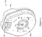
- FIG. 1is a schematic perspective view of an illustrative damper system and a duct section
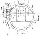
- FIG. 2is a schematic front view of the illustrative damper system and duct section of FIG. 1 , with insulation material represented by a dotted line;
- FIG. 3is a schematic top view of the illustrative damper system and duct section of FIG. 1 ;
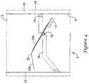
- FIG. 4is a schematic cross-sectional view of the illustrative damper system and duct section taken along line 4 - 4 of FIG. 2 ;
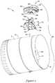
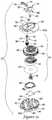
- FIG. 5is a schematic exploded perspective bottom view of the illustrative damper system and duct section of FIG. 1 ;
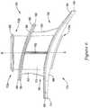
- FIG. 6is a schematic side view of an illustrative standoff of the illustrative damper system of FIG. 1 ;
- FIG. 7is a schematic perspective cross-sectional view of the illustrative standoff of FIG. 6 .
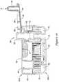
- FIG. 8is a schematic perspective top view of an illustrative damper actuator of the illustrative damper system of FIG. 1 ;
- FIG. 9is a schematic perspective bottom view of the illustrative damper actuator of FIG. 8 ;
- FIG. 10is a schematic first side view of the illustrative damper actuator of FIG. 8 ;
- FIG. 11is a schematic second side view of the illustrative damper actuator of FIG. 8 ;
- FIG. 12is a schematic exploded perspective top view of the illustrative damper actuator of FIG. 8 ;
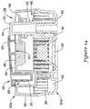
- FIG. 13is a schematic cross-sectional view of the illustrative damper actuator of FIG. 10 taken along line 13 - 13 ;
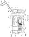
- FIG. 14is a schematic cross-sectional view of the illustrative damper actuator of FIG. 11 taken along line 14 - 14 , with the handle in a first handle position;
- FIG. 15is the schematic cross-sectional view of the illustrative damper actuator of FIG. 14 with the handle in an opened position;
- FIG. 16is the schematic cross-sectional view of the illustrative damper actuator of FIG. 14 with the handle in a second handle position;
- FIG. 17is a schematic bottom perspective view of an illustrative drive gear mechanism.
- FIG. 18is a graphical representation of a change in pressure versus a change in volume flow for a CPRD damper compared to a SPRD damper.
- Forced air zoning systemsmay be used to enable better temperature control in homes and/or buildings by breaking the control and conditioning into small zones. By doing this, the home or building owner cannot only achieve better temperature control, but also realize energy savings by setting unoccupied areas of their home to more energy efficient set points.
- static pressurecan rise in the discharge air plenum of the HVAC system. This static pressure rise can often be mitigated or avoided with multi-stage or variable speed forced air equipment. In many cases, however, forced air equipment in homes or buildings is single stage, which does not usually, by itself, allow for static pressure rise control or the equipment is multi-stage but cannot fully compensate for the static pressure rise.
- undesirable increased static pressurecan occur that may or may not exceed the rated static pressure of the equipment, where the increased static pressure may cause noise in the ducts and/or noise at the discharge registers of the zoned forced air system.
- One solutionmay be to include a bypass damper in the forced air equipment.
- a bypass dampermay assist in reducing the rise in static pressure by opening in response to a rise in static pressure reaching a threshold level and “bypassing” air from the discharge plenum to the supply plenum and/or to any other desired plenum or duct.
- FIGS. 1-3show views of a damper system 10 integrated with or including a duct 2 that may be used with, for example, single stage forced air equipment and/or other equipment.
- the damper system 10may be used to limit the rise in the static pressure when a low percentage of zones in a zone system are calling for air through: facilitating re-circulation of excess air from a supply plenum to a return plenum or other plenum or duct of the forced air HVAC system; providing access to a pressure relief dump zone and dumping excess air into a closet, hallway, or other high load and large zone area; dumping excess air into closed zones (e.g., zones not calling for conditioned air) downstream of the zone control dampers; or through any other technique as desired.
- closed zonese.g., zones not calling for conditioned air
- the damper system 10may be integrated in a duct 2 of a forced air equipment system and may include a damper actuator 20 , an optional standoff 70 , a damper or damper blade 15 , a damper shaft 18 and a damper stop 16 .
- the damper actuator 20may be connected to the standoff 70 and the standoff 70 may be connected to duct 2 with one or more fasteners 80 (e.g., screws, rivets, adhesive, solder, weld, etc.), as seen in FIG. 1 , and/or through any other connection technique (e.g., any mechanical, electrical, or other connection technique).
- the damper shaft 18may extend from the damper actuator 20 through standoff 70 , duct 2 , one or more damper clamps 11 attached to damper blade 15 and to a shaft receiving area adjacent the other side of duct 2 .
- one or more damper shafts 18may extend any portion of the distance or space from damper actuator 20 to the shaft receiving area adjacent the other side of duct 2 , as desired.
- damper shaft 18may engage the damper or damper blade 15 and damper clamps 11 at a position offset from a center axis of the damper blade 15 , as shown in FIG. 2 .
- damper blade 15may include one or more weights 17 placed on or adjacent to or affixed to a surface of the damper blade 15 .
- the one or more weights 17may be placed on a first or large area portion A of blade 15 or a second or small area portion B of blade 15 (shown in FIG.
- a surface area of the first or large portion A of the damper blade 15may be greater than a surface area of the second or small portion B of the damper blade 15 , for example.
- the offset positioning of the shaft 18 with respect to a center axis of the damper blade 15 along with the positioning of the one or more weights 17may result in a center of gravity of the damper blade 15 being offset from a center axis of the damper blade 15 and optionally, substantially located at the rotation axis of the damper blade 15 .
- FIG. 2is a schematic end view of the damper system 10 connected to an insulated duct 2 , where an insulating layer 13 (the outer circumference of which is shown by the dotted line around duct 2 ) is positioned about or at least partially around the duct 2 .
- the insulated duct 2may include an outer surface 12 of the duct 2 , the insulating layer 13 on or abutting the outer surface 12 of the duct 2 , and an outer surface 14 of the insulating layer 13 , where the outer surface 12 of the duct 2 may be an outer layer of a duct or other object at least partially within the insulating layer 13 and the outer surface 14 of the insulating layer 13 may optionally include the outer surface of any layer added to typical insulating layers 13 or an outer surface of any other material positioned about the duct 2 .
- the outer surface 12 of the duct 2may include the surface on which the insulating layer 13 is placed and the outer surface 14 of the insulating layer 13 may be a surface adjacent a second flange 76 of the standoff 70 .
- the standoff 70may be configured to allow the duct 2 to be insulated, while providing substantially unobstructed access to a damper control or damper actuator 20 .
- the unobstructed access to a damper actuator 20 connected to a duct 2 having an insulation layer 13 thereonmay be facilitated by the standoff 70 providing space for the insulation material 13 between the damper actuator 20 and the duct 2 .
- the standoff 70may provide for any distance, as desired, between the duct 2 and a bottom surface of the damper actuator 20 .
- the standoff 70may provide a distance between 0.5 inches and 3 inches between the duct 2 and the bottom surface of the damper actuator 20 in order to facilitate the prevention of sweating (e.g., condensation) on the duct 2 and/or on the damper system 10 .
- the standoff 70may provide a distance between one inch and two inches between the duct 2 and the bottom surface of the damper actuator 20 in order to facilitate the prevention of sweating on the duct 2 and/or on the damper system 10 .
- sweat or condensationmay form on the exterior of the duct 2 due, at least in part, to cool fluid (e.g., conditioned air, etc.) within the duct and a warm and/or humid environment exterior the duct.
- fluide.g., conditioned air, etc.
- the actuatormay be cooler (e.g., similar to the interior of the duct) than the dew point of the air in which the actuator resides and moisture may condense thereon.
- the distance provided by the standoff 70 between the duct 2 and the bottom surface of the damper actuator 20 that is configured to facilitate the prevention of sweatingmay provide space for receiving the insulating layer 13 , where the insulating layer may have a known R-value and may be used to isolate a cool interior of the duct 2 and the shaft 18 from the surrounding environment to prevent sweating.
- Example distances provided by the standoff 70 between the duct 2 and the bottom surface of the damper actuator 20may include distances configured to facilitate receiving one or more insulating layers having R-values between 6 ft 2 ⁇ ° F. ⁇ h/Btu and 8 ft 2 ⁇ ° F. ⁇ h/Btu, 1 ft 2 ⁇ ° F. ⁇ h/Btu and 10 ft 2 ⁇ ° F. ⁇ h/Btu, 1 ft 2 ⁇ ° F. ⁇ h/Btu and 20 ft 2 ⁇ ° F. ⁇ h/Btu, or other R-values, as desired.
- standoff 70may include a first flange 74 and a second flange 76 (e.g., a taping flange) separated, at least partially, by a body 72 to form an open space 92 having one or more ribs 82 extending between the first flange 74 and the body 72 and between the second flange 76 and the body 72 for support.
- the open space 92may be used for any purpose.
- the open space 92may be used for receiving the insulating layer 13 or for other purposes.
- the position of the actuator 20 outside of any insulating layer 13may allow for indicators 44 , 50 , 56 and any indicia depicted on or through housing 60 to be easily viewed and/or read by a user.
- FIG. 3depicts a schematic view of a top of the damper system 10 connected to duct 2 .
- one or more indicators 44 , 50 , 56 , along with a handle 34may be positioned on or adjacent the exterior surface 64 of the housing 60 and/or seen on and/or seen through the exterior surface 64 .
- the exterior surface of the housing 60may include a handle 34 extending therefrom, one or more of a damper blade position indicator 44 , a flow direction indicator 56 , a pressure level indicator 50 and/or other similar or dissimilar maneuvering and indicator mechanisms.
- FIG. 4is a schematic cross-sectional view taken along line 4 - 4 in FIG. 2 of the damper blade 15 within the duct 2 , where the damper blade 15 is in an opened position or a second position.
- the damper blade 15may be considered to be in the opened position when the damper blade 15 or object configured to rotate with the damper blade 15 is not touching the damper stop 16 or at least a portion of the damper blade 15 or object configured to rotate with the damper blade 15 is not touching the damper stop 16 .
- the damper blade 15When the damper blade 15 or object configured to rotate with the damper blade 15 abuts at least a portion of the damper stop 16 and the damper blade 15 forms a seal or a closure within the duct 2 (e.g., substantially blocks a flow through duct 2 ), the damper blade 15 may be considered to be in a closed position or a first position.
- the damper blade 15may be configured in any dimension or shape and may be made of one or more pieces of material, as desired.
- the damper blade 15may be completely straight, may have a bent or angled portion or otherwise may be formed to have an angled portion 15 a and a straight portion 15 b , or may take on any other shape.
- the angled portion 15 amay be bent or formed toward an inlet I of the duct 2 and may be on the first or large portion A of the damper blade 15 , or on any other portion of the damper blade 15 .
- the forming of a portion of the damper blade 15 toward the inlet I of the duct 2may facilitate mitigating pressure rise in the duct 2 by allowing the flow through duct 2 to contact the damper blade 15 in a substantially perpendicular manner as the damper blade 15 opens and/or releases from damper stop 16 .
- the damper blade 15may be made of a plurality of pieces of material that at least partially form the portion of the damper blade angled toward the inlet I.
- the damper stop 16may be positioned interior the duct 2 , as shown in FIG. 4 .
- the damper blade 15may be configured to match the shape of the damper stop 16 to create a seal or closure with damper stop 16 within the duct 2 .
- the damper stop 16may be positioned exterior the duct 2 and may be configured to engage any feature or object that rotates with the damper blade 15 .
- the damper blade stop 16may engage the shaft 18 or a clip or object extending from the shaft 18 , as desired.
- the damper system 10may include a second damper blade stop (not shown) configured to limit the how far the duct may open from its closed position.
- the second damper blade stopmay be positioned interior the duct 2 .
- the second damper stopmay be positioned exterior the duct 2 and may be configured to engage any feature or object that rotates with the damper blade 15 .
- the second damper blade stop 16may engage the shaft 18 or a clip or object extending from the shaft, as desired.
- FIG. 5is a schematic exploded view from a bottom of the damper system 10 , with the damper actuator 20 and duct 2 separated from the standoff 70 .
- the bottom of damper actuator 20may include a connector opening 68 through which a second end 72 b of the standoff 70 may extend to connect with the damper actuator 20 .
- connector release 58may be actuated to release body connector 96 from connector 54 , as discussed in greater detail below.
- the standoff 70may be comprised of one or more pieces of material fitted together and may include a body 72 , a mounting mechanism 73 , and a flange 76 spaced from the mounting mechanism 73 .
- the mounting mechanismmay include, but is not limited to, a first end 72 a of the body 70 and a first flange 74 , where the mounting mechanism 73 and at least the first flange 74 may be configured to facilitate mounting the body 72 relative to a duct 2 adjacent an outer surface 12 of the duct 2 .
- the flange 76may be a second flange 76 spaced from the first flange 74 , where a space 92 configured to receive the insulating layer 13 is formed between the first flange 74 and the second flange 76 .
- the first flange 74may be mounted relative to the outer surface 12 of the duct 2 and the body 72 extends through (or receives) the insulating layer 13 of the duct 2 such that the second flange 76 may be positioned adjacent an outer surface 14 of the insulating layer 13 .
- the standoff 70may be mounted to the duct 2 from inside the duct 2 , where the first flange 74 may be mounted to an inner surface 9 of the duct 2 and the body 72 may be inserted through the duct.
- the second flange 76may facilitate taping the insulation layer to the standoff 70 and may be a taping flange.
- the body 72may have the first end 72 a extending through the first flange 74 and an opposing second end 72 b extending through the second flange 76 , as seen in FIG. 6 , or body 72 may take on any other desired orientation with respect to the first flange 74 and the second flange 76 to create the open space 92 .
- the first flange 74may include one or more mounting holes 78 configured to receive a fastener 80 that may be configured to fasten the first flange 74 to the outer surface 12 or the inner surface 9 of the duct 2 .
- the mounting mechanism 73 and/or the first flange 74may take on a configuration that facilitates a connection to the duct 2 by twisting onto and/or engaging the duct 2 in a bayonet-style and may be held in place with a snap, latch, screw, etc.; the mounting mechanism 73 and/or the first flange 74 may connect to the duct 2 with a nut positioned on or about the duct 2 that may engage threads on the bottom of or that extend from the mounting mechanism 73 and/or the first flange 74 ; the mounting mechanism 73 and/or the first flange 74 may connect to the duct 2 by engaging a retaining part on the inner surface 9 of the duct 2 that snaps onto, slides onto, twists onto, otherwise engages features of the mounting mechanism; the mounting mechanism 73 and/or the first flange 74 may connect to the duct 2 by using an adhesive; the mounting mechanism 73 and/or the first flange 74 may connect to the duct 2 in any other
- the standoff 70may have one or more ribs 82 extending to or from one or more of the flanges 74 , 76 and from or to body 72 .
- one or more ribs 82may extend between the first flange 74 and the body 72 of standoff 70 .
- the rib(s) 82may extend entirely from the first flange 74 to the second flange 76 along body 72 or the rib(s) 82 may extend partially the distance between the flanges 74 , 76 along body 72 .
- the second end 72 b of the standoff 70may connect to a connector 54 (e.g., a clip connector or another connector type) at or near the body connector 96 , such that the housing 60 of the actuator 20 may be fixed with respect to the shaft 18 .
- the body connector 96may be any type of connector configured to engage or facilitate engagement of the standoff 70 with the connector 54 .
- the body connector 96may include a ridge capable of making a snapping or other connection with the connector 54 , as shown in FIG. 6 ; the body connector 96 may include an indentation configured to receive and connect with the connector 54 ; or, the body connector 96 may take on any other form that may be configured to connect with the connector 54 , as desired.
- the body 72 of the standoff 70may have a pass-through cavity 94 that extends from the first end 72 a of the body 72 through to the second end 72 b of the body 72 .
- the pass-through cavity 94may be configured to receive the damper shaft 18 and have shaft 18 pass therethrough. Further, the pass-through cavity 94 may be configured to have a bearing surface 95 configured to engage and/or abut a bearing in communication with the shaft 18 .
- the body 72includes the connector 96 (e.g., a releasable connector) and is connected to the damper actuator 20
- the standoff 70 , the damper actuator 20 , and the damper shaft 18may be configured to drive the damper blade 15 .
- the pass through cavity 94may receive other features and have one or more of those other features pass therethrough.
- one or more wires supporting the sensor or electronic objectmay pass from the duct and at least partially through the pass-through cavity or opening 94 of the standoff 70 .
- the pass through cavity 94 and/or the body 72may be elongated and extend along a main body axis B-B, where the flanges 74 , 76 extend radially outward relative to the main body axis B-B.
- the first flange 74may have a first flange perimeter 84 defined by one more first flange sides 88 , where the first flange 74 extends outward (e.g., extends radially) relative to the main body axis B-B to the first flange perimeter 84 .
- the second flange 76may have a second flange perimeter 86 defined by one or more second flange sides 90 , where the second flange 76 extends outward (e.g., extends radially) relative to the main body axis B-B to the second flange perimeter 86 .
- the first flange perimeter 84may be defined by any number of sides 88 and the second flange perimeter 86 may be defined by any number of sides 90 .
- each perimeter 84 , 86may have one side 88 , 90 (e.g., where the flanges 74 , 76 have a circular and/or rounded shape), respectively; at least two sides 88 , 90 , respectively; at least three sides 88 , 90 , respectively; at least four sides 88 , 90 , respectively; or any other number of sides 88 , 90 , respectively, having sharp or rounded corners, as desired.
- the open space 92 configured to receive an insulating layer 13may extend between the first flange perimeter 84 , the second flange perimeter 86 , and the main body 72 .
- damper actuator 20may include a housing 60 having a bottom 60 a and a top 60 b , with a handle 34 and a connector release or quick release 58 accessible through or from the exterior surface 64 of housing 60 and configured to engage the clip and release the housing 60 from a fixed position with respect to the shaft 18 and/or the standoff 70 .
- a drive gear arm 32 of a drive gear mechanism 28may extend from or extend through or be formed integral with the housing 60 , such that the drive gear arm 32 may be configured to engage the handle 34 .
- the handle 34 and the drive gear arm 32 , along with the drive gear 30may be integrally formed of one or more pieces of material.
- the drive gear arm 32may extend from the housing 60 at a position adjacent a contact surface or area 66 of the housing 60 and connect with handle 34 such that the handle 34 may be configured to hinge about the drive gear arm 32 and about a fulcrum when in an opened or second position.
- the fulcrummay be accomplished by a raised ridge or shoulder extending any distance around the connection of the handle 34 with the drive gear arm 32 , a raised feature (e.g., a bump) on the top surface 37 of the handle 34 that makes contact with a flat, raised or indented surface that at least partially surrounds the connection of the handle 34 with the drive gear arm 32 , or any other feature configured to act like a fulcrum, as desired.
- a raised ridge or shoulderextending any distance around the connection of the handle 34 with the drive gear arm 32
- a raised featuree.g., a bump
- the handle 34may include a bottom surface 36 and a top surface 38 , where the top surface 38 may include brand indicia 55 and/or other markings, as desired.
- the housing 60may form a handle gap 61 below the handle 34 , which may be defined at least partially by the exterior surface 64 of the housing 60 and the bottom surface 36 of the handle 34 .
- the handle gap 61may be configured to facilitate opening the handle 34 by applying a force on the bottom surface 36 , where opening the handle 34 may include moving it from a first position to a second position.
- one or more visual indicatorsmay be visible from the exterior of the housing 60 .
- a damper blade position indicator 44may be viewed on or through or positioned on the exterior of housing 60 .
- a pressure level indicator 50may be viewed on or through or positioned on the exterior of housing 60 .
- an air flow direction indicator 56may be viewed on or through or positioned on the exterior of housing 60 .
- the structure and position of these indicators 44 , 50 , 56are discussed in greater detail below.
- the housing 60may include a connector opening 68 through which an object may engage a connector 54 or any other type of connector.
- the connector 54may be any type of connector configured to receive body connector 96 of the standoff 70 .
- the connectormay be a u-clip connector, as seen in FIG. 12 , or any other desired clip or other connector or fastener.
- a connector release 58may be in communication with the connector 54 and may extend from interior the housing 60 to exterior the bottom side 60 a of housing 60 or to any other position in relation to housing 60 .
- the connector release 58may take on any configuration based at least partially on the type of connector (e.g., clip connector 54 ) used in damper actuator 20
- the connector release 58 depicted in FIG. 9may operate by facilitating a release of an object connected to clip connector 54 through applying a force in the direction of the connector opening 68 to an end of the connector release 58 extending exterior the housing 60 . Once the force is applied to connector release 58 , the connector release may act on an open end of the connector 54 to spread or open the connector and release a body connector 96 inserted through connector 54 .
- the connector 54may be positioned substantially interior the housing 60 .
- the connector 54may be positioned around a connector opening 68 in the housing 60 and may be snapped into place.
- the connector 54may extend through one or more openings in the housing 60 adjacent the connector opening 68 to engage a body connector 96 extending into and/or through the connector opening 68 .
- the connector release 58may be positioned around and/or over the connector 54 and may be configured to slide radially with respect to the connector opening 68 .
- the connector release 58may be connected to housing 60 in any manner, for example, the connector release 58 may be snapped into clasps 67 extending from the interior surface 62 of the housing 60 and may be configured to slide along or within guides 69 .
- the actuator 20may be connected to the standoff 70 in any similar or dissimilar manner, as desired.
- the actuator 20may connect to the standoff 70 by twisting onto and engaging the standoff 70 in a bayonet-style and may be held in place with a snap, latch, screw, etc.; the actuator 20 may be screwed onto the standoff 70 at the second flange 76 and/or with a flange of the housing 60 , where the flanges may be substantially normal or parallel to the shaft 18 ; the actuator 20 may connect to the standoff 70 with a nut positioned on or about the standoff 70 that may engage threads on the bottom of or that extend from the actuator 20 ; the actuator 20 may connect to the standoff 70 with a nut and lever connection; the actuator 20 may connect to the standoff 70 in any other releasable or non-releasable manner;
- the housing 60may include a female key 71 (or a male key or other key, as desired) within the connector opening 68 .
- the female key 71may be configured to engage one or more ribs or male keys 75 (see FIG. 7 ) (or female key or other key, as desired). Any connections between keys 71 , 75 may facilitate fixing the actuator 20 in a position with respect to standoff 70 , the shaft 18 , the duct 2 , and/or other features.
- the connector 54 and the keys 71 , 75may be configured to fix the actuator 20 translationally in three degrees of freedom and rotationally in three degrees of freedom with respect to the standoff 70 , shaft 18 , the duct 2 , and/or other features.
- the locks 71 and 75may be configured to connect the actuator 20 to the standoff 70 such that the actuator may only connect in a single orientation or in a limited number of orientations with respect to the standoff 70 , the shaft 18 , the duct 2 , and/or other features.
- the damper system 10may be used in conjunction with one or more ducts 2 and may include the damper blade 15 positioned within the duct 2 and in communication with the shaft 18 , such that the shaft 18 may be configured to affect movement of the damper blade 15 within the duct 2 and about a damper blade rotation axis between a first position and a second position different than the first position.
- the damper actuator 20may communicate with the shaft 18 to move the damper blade 15 from the first position to the second position.
- the damper actuator 20may include a soft spring and/or a torsion spring 22 (e.g.
- the damper actuator 20may include a housing 60 that at least partially encloses the torsion spring 22 and other features of the damper actuator 20 including, but not limited to, a winding or bias force adjustment mechanism 24 , where the mechanism 24 may be in communication with the torsion spring 22 and may be configured to load the torsion spring 22 or otherwise adjust the bias force provided from the torsion spring 22 to the shaft 18 .
- a soft springmay be a spring having a low stiffness.
- a soft springmay have a low stiffness if it has a stiffness in the range of 0.1 Newton-millimeters/degree to 0.6 Newton-millimeters/degree, 0.02 Newton-millimeters/degree to 1.0 Newton-millimeters/degree, 0.02 Newton-millimeters/degree to 2.0 Newton-millimeters/degree, or other range of stiffness, as desired. Whether a stiffness of a spring is considered a low stiffness may depend at least partially on the size of duct to which the soft spring is to be applied.
- a low stiffness spring used in conjunction with an eight inch ductmay have a stiffness of or about 0.11 Newton-millimeters/degree; a low stiffness spring used in conjunction with a ten inch duct may have a stiffness of or about 0.16 Newton-millimeters/degree; a low stiffness spring used in conjunction with a twelve inch duct may have a stiffness of or about 0.29 Newton-millimeters/degree; and a low stiffness spring used in conjunction with a fourteen inch duct may have a stiffness of or about 0.50 Newton-millimeters/degree.
- the winding or bias force adjustment mechanism 24may include two gears and the back driving clutch or reverse stop mechanism 40 having a stop member 42 and a spring 52 , or may take on a different configuration.
- mechanism 24may include a driven gear 26 in communication with the torsion spring 22 and a drive gear 30 in communication with the driven gear 26 , where the drive gear 30 and/or the driven gear 26 may engage the back driving clutch or reverse stop mechanism 40 to facilitate preventing unintended movement of the gears 26 , 30 in a direction biased by the torsion spring 22 .
- the drive gear 30may be formed as a portion of the drive gear mechanism 28 , which may also include the drive gear arm 32 .
- the drive gear 30may have an end with a chamfered portion 33 leading to a stop member engaging portion 31 , where the stop member engaging portion 31 may be a cut-away in an end of drive gear 30 , as best shown in FIG. 17 , and may be configured to receive or engage the stop member 42 .
- the winding mechanism or bias force adjustment mechanism 24may optionally include features in addition to the driven gear 26 and the drive gear 30 that include, but are not limited to, the handle 34 (not shown as part of the winding mechanism or bias force adjustment mechanism 24 in FIG. 12 ), shaft connector 19 , the torsion spring 22 , torsion spring plate 23 , the drive gear arm 32 , a spring 52 , indicator arms 45 , 51 , spiral groove 48 , and other desired features.
- the handle 34may communicate with the drive gear 30 of the drive gear mechanism 28 through the drive gear arm 32 . Through interaction with the drive gear 30 which may engage driven gear 26 , the handle 34 may drive the driven gear 26 as the handle 34 is actuated (e.g., rotated).
- the torsion spring 22may be in communication with the shaft 18 and the driven gear 26 through a mechanical couple or other direct or indirect coupling to operate in response to actuation of the handle 34 . In some instances, the torsion spring 22 may be positioned substantially between an outer circumference of the shaft 18 and an inner circumference of the driven gear, as best shown in FIG. 13 .
- the torsion spring 22may be directly or indirectly connected to the shaft 18 .
- the torsion spring 22may connect to the shaft connector 19 , which, in turn, may be connected to shaft 18 . Further, as the torsion spring 22 may be in communication with the shaft 18 and the driven gear 26 , the torsion spring 22 may operate to bias the shaft 18 and driven gear 26 in a first direction. In such an instance, the handle 34 may be actuated to move the driven gear 26 in a first or second direction.
- the shaft connector 19may allow for winding or unwinding of the torsion spring 22 through rotation of the driven gear 26 to establish a pressure set point or threshold by adjusting the amount of pressure required to crack open the damper blade 15 from the damper stop 16 (e.g., a crack pressure), while allowing shaft 18 to rotate against the bias of the torsion spring 22 in response to a pressure differential between the inlet and outlet of (e.g., a pressure differential across the damper blade) the duct 2 (or a force against the damper blade 15 ) above the crack pressure and facilitating the indication of a position of the damper blade 15 through the damper blade position indicator 44 .
- a pressure differential between the inlet and outlet ofe.g., a pressure differential across the damper blade
- the duct 2e.g., a force against the damper blade 15
- An established pressure set point or crack pressuremay be a pressure level expressed by a numerical value with some pressure units.
- the established pressure set point or crack pressuremay be set by relative position.
- the pressure set point or crack pressuremay be set relative to tick marks or other markings of the pressure level indicator 50 , where the tick marks or other markings may or may not be related to a known numerical value and may be viewable from exterior the housing 60 .
- a lockmay be utilized to secure the driven gear 26 at a desired position to maintain an established or desired pressure set point or threshold (e.g., a crack pressure).
- a lock of the driven gear 26may result in the torsion spring 22 and the shaft 18 resisting rotational moments to the shaft below the torque applied by the torsion spring 22 , while also preventing the total unwinding of the torsion spring 22 .
- a back driving clutch mechanism or reverse stop mechanism 40may be utilized to lock the driven gear 26 in a particular rotational position.
- the back driving clutch mechanism or reverse stop mechanism 40may be configured to unlock drive gear 30 from a reverse stop member 42 .
- the back driving clutch mechanism or reverse stop mechanism 40may engage the driven gear 26 , as desired.
- the reverse stop mechanism 40may include the reverse stop member 42 extending from an interior surface 62 of the bottom 60 b of the housing 60 .
- a spring 52 positioned about or adjacent the drive gear mechanism 28may be included with the back driving clutch mechanism or reverse stop mechanism 40 or, alternatively, the spring 52 may be separate from the back driving clutch mechanism or reverse stop mechanism 40 .
- the stop member 42 of the reverse stop mechanism 40may take on any shape or size and may be configured to engage the drive gear 30 or other rotational feature in any manner. In some cases, the reverse stop member 42 may be a single feature or a plurality of features extending from the interior surface 62 of the bottom 60 b of the housing 60 .
- the reverse stop member 42may include two features extending from the interior surface 62 of the bottom 60 b of the housing 60 , where at least one of the two features is configured to engage a stop member engaging portion 31 of the drive gear 30 such that a handle 34 is aligned with and/or positioned to fit within a handle opening 65 in the housing 60 .
- reverse stop member 42it may be possible to increase the strength of the reverse stop member 42 and reduce the stress thereon by increasing the number of reverse stop members 42 configured to engage the drive gear 30 or other features.
- having many reverse stop members 42 configured to engage the drive gear 30 or other featuresmay result in shorter time periods for the drive gear 30 to engage the reverse stop member 42 .
- both increasing the strength of the reverse stop member 42 and lowering the amount of time of the time periods for the drive gear 30 to engage the reverse stop member 42may be weighed when designing the reverse stop member 42 .
- one or more other locking techniques or mechanismsmay be utilized.
- the driven gear 26 and/or torsion spring 22may be locked in place through a button or lever mechanism that must be held to wind or unwind the spring 22 ; through a friction lock (e.g., with a gear system having a low gear ration); through any other locking mechanism; and/or any combination thereof.
- the damper blade position indicator 44may be positioned adjacent an exterior of the housing 60 , at least partially (e.g., half way, substantially, etc.) within the housing 60 , and/or so as to be at least partially viewable from the exterior of the housing 60 , where the damper blade position indicator 44 may be configured to display a measure related to the current position of the damper blade 15 within the duct 2 .
- the measuremay include an axial position of the damper blade 15 , a distance of the damper blade 15 from the damper stop 16 , or any other measure related to the current position of the damper blade 15 within the duct 2 .
- a damper blade position indicator arm 45 of the damper blade position indicator 44may be connected to the shaft 18 , such that indicator arm 45 may move in response to movement of the shaft 18 .
- the damper blade position indicator arm 45may be directly connected to the shaft 18 or may be indirectly connected to the shaft 18 through the shaft connector 19 , (as shown in FIG. 13 ).
- the pressure level indicator 50may be positioned adjacent an exterior of the housing 60 that at least partially encloses the torsion spring 22 , at least partially (e.g., half way, substantially, etc.) within the housing 60 , and/or so as to be at least partially viewable from exterior the housing 60 .
- the pressure level indicator 50may be configured to display a measure related to the bias force provided from the torsion spring 22 to the shaft 18 , where the measure related to the bias force may include a pressure set point, pressure level, or force amount applied to the shaft 18 from the torsion spring 22 .
- the pressure level indicator 50may engage a spiral indicator mechanism 46 having a spiral groove 48 configured to rotate about the shaft 18 in response to movement of the driven gear 26 , where each rotation of the spiral indicator mechanism may equal a predetermined change in a crack pressure setting of the damper system 10 .
- the spiral groove 48may be configured on or integrally formed with driven gear 26 (as shown in FIGS. 12 and 13 ).
- the pressure level indicator arm 51 of the pressure level indicator 50may engage the spiral groove 48 while being substantially rotationally fixed to travel linearly by opening 63 , which may result in radial movement of the pressure level indicator arm 51 in response to rotational movement of the spiral indicator mechanism 46 .
- the pressure level indicator arm 51may have a pivot at one end, a needle or other mechanism configured to engage the spiral grooves 48 of the spiral indicator mechanism 46 at another end, and a body extending there between. Such a configuration may facilitate at least partial radial movement of the pressure level indicator arm, in a manner similar to a needle arm of typical record players, in response to rotational movement of the spiral indicator mechanism 46 . In some instances, the pressure level indicator arm 51 may take on other configurations that may facilitate indicating a set crack pressure of the damper system 10 .
- a handle mechanism of or for use with damper actuator 20may include certain features already discussed above, along with other features, as desired.
- the handle mechanismmay include the drive gear mechanism 28 in communication with the driven gear 26 of the damper actuator 20 ; the handle 34 having a first surface (e.g., bottom surface) 36 and a generally opposing second surface (e.g., top surface) 38 , as best shown in FIGS.
- the housing 60at least partially enclosing the drive gear mechanism 28 ; and the spring 52 position about the drive gear mechanism 28 and configured to bias the drive gear mechanism 28 toward a first axial or locked position relative to the housing 60 and the reverse stop member 42 .
- the handle 34may be a flip over handle.
- a flip over handlemay be a handle that is configured to flip over or hinge about a point or axis.
- the drive gear mechanism 28may include the drive gear arm 32 extending from the drive gear 30 and configured to engage the handle 34 .
- the handle 34may be configured to flip or hinge about or over the drive gear arm 32 between a first handle position (e.g., a closed position) and a second handle position (e.g., an opened position).
- the handle 34may be configured in the first handle position when the first surface 36 of the handle 34 is adjacent the exterior surface 64 of the housing 60 , as shown in FIG.
- the handle 34may be configured in the second handle position when the second surface 38 of the handle 34 is adjacent the exterior surface 64 of the housing, as shown in FIGS. 15 and 16 . Further, when the handle 34 is in the first or closed position, the handle 34 may be locked in place with a snap fit, pressure fit, or other connection.
- a handle extension 35 or other portion of handle 34may have a snap connection or pressure fit connection with one or more walls of the handle opening 65 and/or other portion(s) of the housing 60 to facilitate preventing inadvertent movement of the handle 34 .
- the first position of the handle 34may allow for storing of the handle 34 in a position that mitigates the likelihood of snagging insulation as it is brought over the damper actuator 20 during installation.
- the drive gear arm 32may be configured to effect axial movement of the drive gear 30 along the drive gear rotation axis or longitudinal axis D-D.
- a forcee.g., a light force
- the handlemay use the contact area 66 as a fulcrum or pivot and act on the drive gear mechanism 28 to move the drive gear mechanism 28 up from the first axial or locked position relative to the housing 60 , as shown in FIGS.
- FIG. 16to a second axial or unlocked elevated position relative to the housing 60 , as shown in FIG. 16 .
- Removing the force F from the first side 36 of the handle 34may cause the spring to move or bias the drive gear mechanism 28 back to the lowered first axial position.
- the first axial position of the drive gear mechanism 28is depicted in FIGS. 14 and 15 , where the drive gear 30 of the drive gear mechanism 28 is in or near contact with the interior surface 62 of the housing 60 and stop member 42 .
- the second axial position of the drive gear mechanism 28is depicted in FIG. 16 , where a bottom of the drive gear 30 of the drive gear mechanism 28 is positioned above stop member 42 , such that drive gear 30 may be disengaged from the reverse stop mechanism 40 and may rotate freely about its axis D-D.
- the handle 34may be configured to effect rotational movement of the drive gear 30 .
- the handle 34may be rotated about the drive gear longitudinal or rotation axis D-D and that rotation may cause rotational movement of the drive gear arm 32 and the drive gear 30 .
- Such rotational movement of the drive gear 30 by the handle 34may rotate the driven gear 26 to set the crack pressure for the damper system 10 .
- the damper system 10may be utilized to set a crack pressure (e.g., note, crack pressure may be the minimum amount of pressure within a duct 2 that triggers or actuates movement of the blade 15 within the duct 2 ) of a bypass duct 2 of an HVAC duct system.
- the crack pressuremay be set by disengaging the drive gear mechanism 28 from the reverse stop mechanism 40 by opening up the flip over handle to an opened or second position and applying a force to the handle in the direction of housing 60 and the contact area 66 .
- the drive gear 30 of the drive gear mechanism 28may be rotated by rotating the flip over handle 34 while the handle 34 is in the opened position in order to set the crack pressure.
- the crack pressure of the duct 2e.g., the bypass duct
- the force applied to the handlemay be released and the drive gear mechanism 28 may automatically mechanically lock in place by engaging the drive gear 30 with the reverse stop member 42 due, at least partially, to a bias force of the spring 52 .
- the handle 34may be flipped from the second handle position or opened position to the first handle position or closed position to further lock the drive gear mechanism 28 in its desired position.
- the damper system 10 having a mechanical actuator 20 or other actuatormay facilitate better control of static pressure rise than in systems with typical static pressure regulating dampers (SPRDs) due, at least partially, to the relatively precise and secure crack pressure adjustment capabilities of the damper system 10 .
- SPRDstypically include a weighted arm to bias the damper in the bypass duct in a particular position and the ability or opportunity to calibrate or adjust the position of the damper is limited.
- Use of such a damping systemmay lead to a large increase in pressure (measured in inches of water, “in we”) as a bypass flow (measured in cubic feet per minute, “cfm”) increases in volume.
- cfmcubic feet per minute
- the load on the blower of the HVAC systemmay be increased, possibly shortening the life of the equipment.
- CPRDconstant pressure regulating damper
- the pressure rise in the bypass duct due to an increased flow volumecan be reduced or lowered with respect to the pressure rise as the volume of flow increases in a bypass duct having a SPRD system, as shown in the graph of FIG. 18 .
- the torsion spring 22may provide a more linear bias force to the damper blade over the range of movement of the damper blade. This may facilitate keeping the differential pressure across the damper blade 15 in the duct 2 relatively flat (e.g., relatively constant) over a wide range of flow volume (e.g., an operating volume flow rate), as also shown in the graph of FIG. 18 .
- Typical operating volume flow ratesmay differ depending on the size or configuration of the duct 2 , the damper blade 15 , and/or other factors.
- a relatively flat differential pressure across the damper blade 15 over a wide range of volume flow ratemay be generally depicted by a flat curve over an operating volume flow rate for a specific damper system.
- a curve of a pressure differential across the damper blade 15 over an operating volume flow rate for a specific damper sizemay be considered flat when a change in differential pressure over the operating volume flow rate range does not exceed one or more particular thresholds (e.g., 0.1 inches of water, 0.2 inches of water, 0.4 inches of water).
- Example operating volume flow rate rangesinclude, but are not limited to, ranges of 100 cfm (e.g., a minimum operating volume flow rate) to 2,000 cfm (e.g., a maximum operating volume flow rate), 0 cfm to 2000 cfm, 0 cfm to 5000 cfm and other similar and dissimilar typical operating volume flow rate ranges.
- the minimum or lower operating volume flow rate for a duct 2 or damper system 10may generally be 0 cfm, 100 cfm, any volume flow rate therebetween, and/or any other volume flow rate less than the maximum or upper operating volume flow rate.
- the maximum or upper operating volume flow rate for a duct 2 or damper system 10may be the volume flow rate that results when the average velocity of a fluid flowing through the duct 2 or system 10 is, for example, fifteen feet per second, twenty feet per second, twenty-five feet per second, thirty-five feet per second, forty feet per second, any average velocity in the range of fifteen feet per second to forty-five feet per second, any other average velocity of a fluid flowing through the duct 2 or damper system 10 that results in a volume flow rate greater than the minimum or lower operating volume flow rate.
- a curve of a pressure differential across the damper blade 15may be flat if the change in pressure differential across the damper blade 15 over a sub-range of the operating volume flow rate does not exceed a particular threshold.
- the particular thresholdmay be determined so as to provide a damper system 10 causing fewer harmonic motions and lower noise levels than typical SPRD systems.
- a curve of the pressure differential across the damper blade 15may be flat if the change in pressure differential across the damper blade 15 is less than a particular threshold (e.g., 0.1 inches of water, 0.2 inches of water, 0.3 inches of water, 0.4 inches of water) over a sub-range of at least 600 cfm in width (e.g., 0-600 cfm, 500-1100 cfm, 700-1500 cfm, 200-1800 cfm) of the operating volume flow rate range.
- a particular thresholde.g., 0.1 inches of water, 0.2 inches of water, 0.3 inches of water, 0.4 inches of water
- 600 cfm in widthe.g., 0-600 cfm, 500-1100 cfm, 700-1500 cfm, 200-1800 cfm
- the design of the damper blade 15further reduces the pressure rise due to increased responsiveness of the damper blade 15 to an incoming flow.
- a portione.g., an outermost radius of the damper blade 15 or other portion of the damper blade 15
- This configuration of the damper blade 15results in a damper blade 15 that is more responsive to an incoming flow because the air continues to contact the damper blade 15 at a substantially perpendicular angle as the damper blade 15 is opened.
- the standoff 70 , the clip connector 54 , the quick release 58 and other features of the damper system 10may be utilized to facilitate affecting movement of the damper blade 16 in response to the electrical or electromechanical damper actuator interacting with and/or in communication with the damper shaft 18 .
- the spirit of the disclosuremay be realized by substituting at least a portion of the electrical or electromechanical damper actuator for the mechanical actuator 20 .
Landscapes
- Engineering & Computer Science (AREA)
- General Engineering & Computer Science (AREA)
- Mechanical Engineering (AREA)
- Chemical & Material Sciences (AREA)
- Combustion & Propulsion (AREA)
- Air-Flow Control Members (AREA)
Abstract
Description
Claims (19)
Priority Applications (1)
| Application Number | Priority Date | Filing Date | Title |
|---|---|---|---|
| US16/375,711US10697554B2 (en) | 2012-06-14 | 2019-04-04 | Spring loaded HVAC damper |
Applications Claiming Priority (2)
| Application Number | Priority Date | Filing Date | Title |
|---|---|---|---|
| US13/523,754US10302207B2 (en) | 2012-06-14 | 2012-06-14 | Spring loaded HVAC damper |
| US16/375,711US10697554B2 (en) | 2012-06-14 | 2019-04-04 | Spring loaded HVAC damper |
Related Parent Applications (1)
| Application Number | Title | Priority Date | Filing Date |
|---|---|---|---|
| US13/523,754ContinuationUS10302207B2 (en) | 2012-06-14 | 2012-06-14 | Spring loaded HVAC damper |
Publications (2)
| Publication Number | Publication Date |
|---|---|
| US20190234523A1 US20190234523A1 (en) | 2019-08-01 |
| US10697554B2true US10697554B2 (en) | 2020-06-30 |
Family
ID=49754804
Family Applications (2)
| Application Number | Title | Priority Date | Filing Date |
|---|---|---|---|
| US13/523,754Active2036-10-19US10302207B2 (en) | 2012-06-14 | 2012-06-14 | Spring loaded HVAC damper |
| US16/375,711ActiveUS10697554B2 (en) | 2012-06-14 | 2019-04-04 | Spring loaded HVAC damper |
Family Applications Before (1)
| Application Number | Title | Priority Date | Filing Date |
|---|---|---|---|
| US13/523,754Active2036-10-19US10302207B2 (en) | 2012-06-14 | 2012-06-14 | Spring loaded HVAC damper |
Country Status (1)
| Country | Link |
|---|---|
| US (2) | US10302207B2 (en) |
Families Citing this family (25)
| Publication number | Priority date | Publication date | Assignee | Title |
|---|---|---|---|---|
| US8956207B2 (en)* | 2011-12-13 | 2015-02-17 | Controlled Holdings, Llc | Barometric relief air zone damper |
| US8887655B2 (en) | 2012-01-25 | 2014-11-18 | Honeywell International Inc. | Valve actuator with position indicator extension |
| US9664409B2 (en) | 2012-06-14 | 2017-05-30 | Honeywell International Inc. | HVAC damper system |
| US9423143B2 (en) | 2013-12-18 | 2016-08-23 | Honeywell International Inc. | HVAC actuator with light indicator |
| US9623523B2 (en) | 2013-12-18 | 2017-04-18 | Honeywell International Inc. | HVAC actuator with taping flange |
| US9568207B2 (en) | 2013-12-18 | 2017-02-14 | Honeywell International Inc. | HVAC actuator with removable wire blocking tab |
| US10941960B2 (en) | 2013-12-18 | 2021-03-09 | Ademco Inc. | HVAC actuator with position indicator |
| US9732980B2 (en) | 2013-12-18 | 2017-08-15 | Honeywell International Inc. | HVAC actuator with range adjustment |
| USD728071S1 (en) | 2013-12-27 | 2015-04-28 | Honeywell International Inc. | HVAC actuator |
| US10203703B2 (en) | 2014-03-04 | 2019-02-12 | Mi Valve, Llc | Airflow balancing valve for HVAC systems |
| DE202016101720U1 (en)* | 2016-03-31 | 2017-07-03 | Jasta-Armaturen Gmbh & Co. Kg | butterfly valve |
| US10598404B2 (en) | 2016-06-29 | 2020-03-24 | Research Products Corporation | Damper with adjustable resistance to blade motion |
| JP6782396B2 (en)* | 2016-09-27 | 2020-11-11 | パナソニックIpマネジメント株式会社 | Shutter structure |
| US10222088B2 (en)* | 2017-02-01 | 2019-03-05 | Ips Corporation | Adaptive exhaust vent |
| FR3080149B1 (en)* | 2018-04-13 | 2020-09-04 | Safran Aircraft Engines | AIR SAMPLING DEVICE FOR AN AIRCRAFT ENGINE |
| US11713895B2 (en) | 2019-01-14 | 2023-08-01 | Research Products Corporation | Multi-zone environmental control system |
| US11274581B2 (en) | 2019-07-26 | 2022-03-15 | Tenneco Automotive Operating Company Inc. | Externally mounted in-line exhaust gas valve |
| US10961923B2 (en) | 2019-07-26 | 2021-03-30 | Tenneco Automotive Operating Company Inc. | Externally mounted in-line exhaust gas valve |
| US11371402B2 (en) | 2019-07-26 | 2022-06-28 | Tenneco Automotive Operating Company Inc. | Externally mounted in-line exhaust gas valve |
| CN110702400B (en)* | 2019-11-14 | 2024-10-22 | 宜昌达瑞机电科技有限公司 | BYD distributor blows angle wind channel buckle detection device |
| US11274749B1 (en)* | 2021-07-13 | 2022-03-15 | Setbc, Llc | Variable flow adjustable valves |
| US20230024902A1 (en)* | 2021-07-26 | 2023-01-26 | Balraj Banger | Volume Damper Insert |
| CN113983178A (en)* | 2021-11-10 | 2022-01-28 | 珂林智造(天津)有限公司 | An inner card opening type liquid packaging bag drainage butterfly valve and production method thereof |
| CN115479132B (en)* | 2022-09-28 | 2023-04-07 | 杭州西蒙电器有限公司 | Fireproof check valve for public flue |
| CN115823269B (en)* | 2022-12-19 | 2023-07-14 | 广东福斯特流体技术有限公司 | Worm gear direct-insertion butterfly valve and mounting method thereof |
Citations (259)
| Publication number | Priority date | Publication date | Assignee | Title |
|---|---|---|---|---|
| US154798A (en) | 1874-09-08 | Improvement in dampers | ||
| US371776A (en) | 1887-10-18 | Stove-pipe damper | ||
| US502203A (en) | 1893-07-25 | Stovepipe-damper | ||
| US633890A (en) | 1898-09-01 | 1899-09-26 | Horatio J Noyes | Damper. |
| US833554A (en) | 1906-02-08 | 1906-10-16 | Anna Schwoll | Stovepipe-damper. |
| US940182A (en) | 1909-03-25 | 1909-11-16 | John B Morgan | Radiator-valve. |
| US1013819A (en) | 1911-08-30 | 1912-01-02 | Heyman Rosenberg | Damper. |
| US1033866A (en) | 1910-07-05 | 1912-07-30 | Berlin Machine Works | Spiral indicator. |
| US1613322A (en) | 1921-03-21 | 1927-01-04 | Julius F Goetz | Muffler |
| US1710515A (en) | 1928-09-04 | 1929-04-23 | Roman Simon | Safety gas valve |
| US2037363A (en) | 1934-06-14 | 1936-04-14 | Surface Combustion Corp | Fuel valve and damper control for furnaces |
| US2259973A (en) | 1939-10-09 | 1941-10-21 | Welton E Firehammer | Furnace control |
| US2289579A (en) | 1940-02-15 | 1942-07-14 | Carl J Klermund | Adjustable automatic draft regulator |
| US2327980A (en) | 1941-12-22 | 1943-08-31 | Crane Co | Automatic declutching means |
| US2465162A (en) | 1945-12-12 | 1949-03-22 | Niles Bement Pond Co | Dehydrating system |
| US2475799A (en) | 1946-07-26 | 1949-07-12 | Sears Roebuck & Co | Barometric draft control |
| US2514446A (en) | 1947-02-28 | 1950-07-11 | Jr Edward A Field | Draft limiting damper |
| US2538190A (en) | 1945-08-29 | 1951-01-16 | Perfex Corp | Barometric damper |
| US2546714A (en) | 1946-02-18 | 1951-03-27 | William J Adams | Motor operated flue damper carrying a pressure operated auxiliary damper |
| US2616452A (en) | 1951-03-06 | 1952-11-04 | Skinner Chuck Company | Electromagnetic valve construction |
| US2735669A (en) | 1956-02-21 | seiler | ||
| US2745360A (en) | 1952-07-14 | 1956-05-15 | Magor Car Corp | Hopper outlet valve structure |
| US2761494A (en) | 1953-01-26 | 1956-09-04 | Edward A Field | Barometric draft regulator and burner control |
| US2837991A (en) | 1954-03-30 | 1958-06-10 | Hart & Cooley Mfg Co | Damper construction for air outlets |
| US2958065A (en) | 1959-03-17 | 1960-10-25 | Jr William H Flanagan | Electrical assembly |
| US2987330A (en) | 1956-10-16 | 1961-06-06 | Robertson Co H H | Sealed pipe to pipe to wall joint |
| US3070345A (en) | 1961-08-11 | 1962-12-25 | Maschf Augsburg Nuernberg Ag | Pipe line valve |
| US3117257A (en) | 1962-02-02 | 1964-01-07 | Anderson Controls Inc | Solenoid having a rotatable back stop for the plunger |
| US3143137A (en) | 1960-05-24 | 1964-08-04 | Muller Jacques | Quick-acting biased valved coupling for fluid pipe |
| US3147054A (en) | 1962-06-14 | 1964-09-01 | Rca Corp | Test point extender for circuit boards |
| US3172424A (en) | 1962-07-24 | 1965-03-09 | Crawford K Stillwagon | Disc type check valve |
| US3206119A (en) | 1963-10-31 | 1965-09-14 | William F Steinen | Draft regulator |
| US3230971A (en) | 1966-01-25 | Self-indicating relief valve | ||
| US3262027A (en) | 1964-04-06 | 1966-07-19 | Automatic Switch Co | Solenoid structure and mounting means therefor |
| US3276480A (en) | 1965-07-01 | 1966-10-04 | Barber Colman Co | Regulator for constant volume of gas flow |
| US3279744A (en) | 1964-03-09 | 1966-10-18 | Clary Corp | Valve actuator |
| US3295079A (en) | 1964-12-03 | 1966-12-27 | Honeywell Inc | Solenoid actuator assembly having a unitary spring clip for the plunger |
| US3311302A (en) | 1965-03-01 | 1967-03-28 | Danzer Metal Works Co | Two-way damper with adjustable sensitivity |
| US3329394A (en) | 1964-12-09 | 1967-07-04 | Hale Company | Lockable valve handle |
| US3384112A (en) | 1965-12-15 | 1968-05-21 | John W Woolley | Island check valve |
| US3402654A (en) | 1966-05-04 | 1968-09-24 | American Air Filter Co | Ventilation control |
| US3521659A (en) | 1967-05-18 | 1970-07-28 | Blaw Knox Co | High temperature valve for throttling or three-way application |
| US3727160A (en) | 1972-03-24 | 1973-04-10 | Automatic Switch Co | Retaining clip for a solenoid assembly |
| US3817452A (en) | 1973-01-26 | 1974-06-18 | Tempmaster Corp | Duct pressure actuated variable volume device |
| US3847210A (en) | 1972-09-14 | 1974-11-12 | J Wells | Damper sequencer |
| US3889924A (en) | 1973-12-03 | 1975-06-17 | Anchor Darling Valve Co | Valve stem operator |
| US4088150A (en) | 1975-08-05 | 1978-05-09 | Angelo Serratto | Valve for the automatic flow control of a fluid in a conditioning system |
| US4108369A (en) | 1977-03-28 | 1978-08-22 | Prikkel Iii John | Automatic flue damper |
| US4137945A (en) | 1976-06-01 | 1979-02-06 | W. A. Deutsher Pty. Ltd. | Gas tap |
| US4177716A (en) | 1978-02-21 | 1979-12-11 | Gerald J. Bowe | Automatic energy saver and fire damper for exhaust systems |
| EP0021885A1 (en) | 1979-06-07 | 1981-01-07 | Jean Gachot | Handle for operating a valve |
| US4272036A (en) | 1978-08-03 | 1981-06-09 | Keson Industries, Inc. | Line reel |
| US4277019A (en) | 1980-05-12 | 1981-07-07 | Shreve James S | Electrically-controlled damper |
| US4284235A (en) | 1979-12-19 | 1981-08-18 | Werner Diermayer | Vent control arrangement for combustion apparatus |
| US4301833A (en) | 1979-10-05 | 1981-11-24 | Donald Iii Robert A | Flow responsive safety valve |
| US4319714A (en) | 1978-02-17 | 1982-03-16 | Societe Anonyme Francaise Du Ferodo | Device for setting a valve |
| EP0057780A1 (en) | 1981-02-11 | 1982-08-18 | AMP INCORPORATED (a New Jersey corporation) | Electrical connector with a terminal having a slotted wire receiving portion and wire strain relief means |
| USD267335S (en) | 1980-03-06 | 1982-12-21 | Edwin Axel | Storm water outlet |
| US4379605A (en) | 1980-11-17 | 1983-04-12 | Harvey Hubbell Incorporated | Electrical receptacle of molded body construction |
| US4399940A (en) | 1982-04-23 | 1983-08-23 | Stiles Donald E | Automatic stove damper control |
| US4431134A (en) | 1982-11-08 | 1984-02-14 | Microcomm Corporation | Digital thermostat with protection against power interruption |
| US4487363A (en) | 1982-10-14 | 1984-12-11 | Parker Electronics, Inc. | Bypass control system to maintain a constant air supply pressure in a HVAC duct system |
| US4533114A (en) | 1983-02-08 | 1985-08-06 | Posi-Seal International, Inc. | Fail-safe actuator for rotary valves |
| US4534538A (en) | 1983-07-08 | 1985-08-13 | The United States Of America As Represented By The Secretary Of The Air Force | Modular air shut-off valve |
| US4549446A (en) | 1984-02-06 | 1985-10-29 | Johnson Service Company | Motorized valve actuator |
| USD286907S (en) | 1983-09-19 | 1986-11-25 | Georg Fischer Aktiengesellschaft | Hydraulic or pneumatic actuator unit for valves |
| US4671540A (en) | 1984-02-27 | 1987-06-09 | Swagelok Company | Coupling |
| US4683453A (en) | 1985-11-25 | 1987-07-28 | Automatic Switch Company | Solenoid actuator with fastener |
| US4691689A (en) | 1985-12-06 | 1987-09-08 | B. D. Wait Co. Limited | One piece adjustable damper |
| US4694851A (en) | 1983-05-20 | 1987-09-22 | Halton Oy | Flow regulator and its use |
| US4732318A (en) | 1986-01-17 | 1988-03-22 | Osheroff Gene W | Velocity controlled forced air temperature control system |
| USD295280S (en) | 1985-04-25 | 1988-04-19 | Georg Fischer Aktiengesellschaft | Valve actuator |
| US4751458A (en) | 1984-04-02 | 1988-06-14 | American Telephone And Telegraph Company, At&T Bell Laboratories | Test pads for integrated circuit chips |
| US4759726A (en) | 1985-08-13 | 1988-07-26 | Reed Devices, Inc. | Screwless type electrical terminal block |
| US4805870A (en) | 1983-02-03 | 1989-02-21 | Emerson Electric Co. | Coil retainer for solenoid |
| US4829447A (en) | 1987-06-22 | 1989-05-09 | Parker Electronics, Inc. | Bypass controller and bypass system |
| US4836497A (en) | 1988-03-08 | 1989-06-06 | Johnson Controls, Inc. | Adjustable valve linkage |
| US4841733A (en) | 1988-01-07 | 1989-06-27 | Dussault David R | Dri-Pc humidity and temperature controller |
| US4844115A (en) | 1988-10-31 | 1989-07-04 | Bowers Rudy M | Butterfly valve |
| US4926903A (en) | 1989-05-05 | 1990-05-22 | Tomoe Technical Research Company | Butterfly valve having a function for measuring a flow rate and method of measuring a flow rate with a butterfly valve |
| US5052537A (en) | 1989-12-14 | 1991-10-01 | Sundstrand Corporation | Rotary travel limit stop apparatus |
| US5058492A (en) | 1990-03-02 | 1991-10-22 | Doug Norton | Insulated diffuser for evaporative air cooling system |
| US5090445A (en) | 1991-02-19 | 1992-02-25 | Jackson Bert W | Air actuated damper |
| US5133265A (en) | 1991-04-08 | 1992-07-28 | Tab Products Company | Visual indicator with aligning ridges for indicating the status of a carriage lock for a mobile storage system having a rotatable lock actuator knob |
| US5169121A (en) | 1990-12-24 | 1992-12-08 | Mitsubishi Electronics America, Inc. | Damper control mechanism |
| US5236006A (en) | 1992-04-22 | 1993-08-17 | Platusich Bruce M | Insulated HVAC valve assembly |
| US5249596A (en) | 1992-03-06 | 1993-10-05 | Carrier Corporation | Residential heating and air conditioning barometric bypass damper |
| US5317670A (en) | 1991-10-19 | 1994-05-31 | Paul Elia | Hot water storage system |
| US5334095A (en) | 1992-12-30 | 1994-08-02 | Colling George J | Rotary coupler with shaft misalignment and overtravel tolerance |
| US5338221A (en) | 1993-06-09 | 1994-08-16 | Molex Incorporated | Electrical connector for high density ribbon cable |
| EP0612950A1 (en) | 1993-02-26 | 1994-08-31 | TRW United-Carr GmbH | Clamping connection |
| US5385505A (en)* | 1993-07-02 | 1995-01-31 | Phoenix Controls Corporation | Pressure maintenance system for substantially sealed space |
| US5393106A (en) | 1993-09-15 | 1995-02-28 | Casco Manufacturing | Sealed knock-down duct collar |
| USD359103S (en) | 1993-01-19 | 1995-06-06 | Mueller Co. | Valve |
| US5518462A (en) | 1994-08-12 | 1996-05-21 | Jordan Controls, Inc. | Spring return electric actuator |
| US5518277A (en) | 1991-09-03 | 1996-05-21 | Gcs Innovations, Inc. | Single piece duct connector for leakfree attachment to sidewall of highly flexible trunkline duct |
| US5540414A (en)* | 1994-05-03 | 1996-07-30 | Taco, Inc. | Actuator and zone valve |
| US5551477A (en) | 1994-07-08 | 1996-09-03 | Kabushiki-Kaisha Motoyama Seisakusho | Diaphragm-type flow control valve and manual control valve apparatus |
| US5564461A (en) | 1995-11-09 | 1996-10-15 | Bray International, Inc. | Assembly for connecting an actuator to a rotary valve |
| US5581232A (en) | 1992-06-18 | 1996-12-03 | Mitsubishi Jidosha Kogyo Kabushiki Kaisha | Ultrasonic wave reception apparatus and obstacle detection apparatus |
| US5588682A (en) | 1995-06-26 | 1996-12-31 | Schwler Manufacturing Company Inc. | Electrically insulating gas line system |
| US5635674A (en) | 1994-06-13 | 1997-06-03 | Owen; Donald W. | Sealed passage for electrical leads across a barrier |
| US5634486A (en) | 1993-09-13 | 1997-06-03 | Itt Richter Chemie-Technik Gmbh | Valve assembly with connection between an angularly displaceble member and actuator |
| US5637835A (en) | 1995-05-26 | 1997-06-10 | The Foxboro Company | Automatic test detection of unsoldered thru-hole connector leads |
| US5669815A (en) | 1996-04-26 | 1997-09-23 | Martin Industries, Inc. | Barometric damper with magnetic latch |
| US5743709A (en) | 1995-06-01 | 1998-04-28 | Honeywell Consumer Products, Inc. | Oscillating window fan |
| US5808534A (en) | 1996-07-30 | 1998-09-15 | Laffey; James | Solenoid frame and method of manufacture |
| US5806555A (en) | 1997-01-31 | 1998-09-15 | Spears Manfacturing Co. | Locking device for valves |
| US5819791A (en) | 1997-11-04 | 1998-10-13 | Gulf Valve Company | Check valve including means to permit selective back flow |
| US5835981A (en) | 1997-01-07 | 1998-11-10 | Communications Technology Corporation | Terminal block mounting method and apparatus |
| US5921527A (en) | 1995-12-22 | 1999-07-13 | Denso Corporation | Rotary-type door apparatus having two engagement portions for manual or automatic driving |
| US5921277A (en) | 1997-04-24 | 1999-07-13 | Bernal; Richard G. | Air duct damper |
| US5934994A (en) | 1997-03-12 | 1999-08-10 | Beutler Heating & Air Conditioning | Damper apparatus including plenum and multiple damper blades |
| US5934644A (en) | 1993-12-18 | 1999-08-10 | Saia Ag Industrie-Elektronik Und Komponenten Behr Gmbh & Co | Setting device for a ventilation flap |
| US5944224A (en) | 1997-03-18 | 1999-08-31 | Outer Circle Products, Ltd. | Insulated vessel with handle and dispensing spout |
| US5947445A (en) | 1996-08-30 | 1999-09-07 | Bs&B Safety Systems, Inc. | Rotatable valve assembly |
| US5954088A (en) | 1998-07-17 | 1999-09-21 | Transworld Steel Enterprise Corp. | Ball valve adapted to couple with an output drive shaft of a valve control device |
| US5963045A (en) | 1995-12-29 | 1999-10-05 | Hewlett Packard Company | Method for testing circuit board assemblies |
| JPH11280948A (en) | 1998-03-27 | 1999-10-15 | Hitachi Chem Co Ltd | Operating lever of mixing valves for water combination faucet |
| WO2000002289A1 (en) | 1998-07-02 | 2000-01-13 | Ulrich Weitzel | Line distributor for telecommunications and security installations |
| US6015142A (en) | 1997-09-12 | 2000-01-18 | Johnson Controls, Inc. | Spring module for return-to-normal actuator |
| EP0976957A2 (en) | 1998-07-29 | 2000-02-02 | Karl Dungs GmbH & Co. | Servo pressure controller with stepped magnet armature |
| US6073907A (en) | 1997-11-07 | 2000-06-13 | Erie Manufacturing Company | Removable and interchangeable valve actuator system |
| US6089034A (en) | 1998-11-12 | 2000-07-18 | Daimlerchrysler Corporation | Controller for reversible air conditioning and heat pump HVAC system for electric vehicles |
| US6179214B1 (en) | 1999-07-21 | 2001-01-30 | Carrier Corporation | Portable plug-in control module for use with the service modules of HVAC systems |
| US6198243B1 (en) | 1999-02-23 | 2001-03-06 | Johnson Controls Technology Co. | Method for automatically determining range of movement of an electromechanical actuator |
| US6196467B1 (en) | 1997-02-19 | 2001-03-06 | Dushane Steve | Wireless programming or programmable thermostat mobile unit for multiple separate controller or programmable fixed units and programming transmission method |
| US6422258B1 (en) | 2000-07-21 | 2002-07-23 | Emerson Electric Co. | Snap-and-crimp appliance water valve assembly and associated method for making the same |
| US6431203B1 (en) | 1999-02-01 | 2002-08-13 | Honeywell International Inc. | Actuator mounting assembly |
| EP1235128A2 (en) | 2001-02-27 | 2002-08-28 | Behr Thermot-tronik GmbH | Means for applying an actuator or a thermostat head on a valve |
| KR20030013488A (en) | 2003-01-08 | 2003-02-14 | 박실상 | Knob of ballvalve |
| US6561161B2 (en) | 2000-02-10 | 2003-05-13 | Siemens Aktiengesellschaft | Throttle valve configuration having an emergency air device |
| US6578686B2 (en) | 2000-11-15 | 2003-06-17 | Honeywell International Inc. | Actuator drive and display mechanism |
| US6581846B1 (en) | 2002-03-06 | 2003-06-24 | Howard B. Rosen | Thermostat including a vacation mode in which electrical devices within and proximate the conditioned space are operated by the thermostat to provide an occupied appearance |
| USD480450S1 (en) | 2002-05-16 | 2003-10-07 | Zurn Industries, Inc. | Flush valve actuator |
| US6676109B2 (en) | 2001-05-22 | 2004-01-13 | Kitz Corporation | Rotary valve |
| US6684264B1 (en) | 2000-06-16 | 2004-01-27 | Husky Injection Molding Systems, Ltd. | Method of simplifying machine operation |
| US6684901B1 (en) | 2001-08-23 | 2004-02-03 | Deltrol Controls | Modular liquid dispensing valve |
| US20040099833A1 (en) | 2001-01-26 | 2004-05-27 | Yamatake Corporation | Actuator for driving rotary valve actuator and valve device with the actuator |
| US6742765B2 (en) | 2001-01-10 | 2004-06-01 | Yamatake Corporation | Operating device and valve system |
| US6789781B2 (en) | 2001-03-16 | 2004-09-14 | Entegris, Inc. | Reinforced diaphragm valve |
| US6817378B2 (en) | 2001-04-04 | 2004-11-16 | Abco Consulting, Inc. | Fluid flow control damper assembly |
| USD498821S1 (en) | 2004-01-20 | 2004-11-23 | Sloan Valve Company | Actuator housing for a flush valve |
| DE10322832A1 (en) | 2003-05-19 | 2004-12-16 | Georg Fischer Rohrleitungssysteme Ag | Emergency hand-operation system for valve has handle with plug or screwdriver arrangement engaging in socket and has blade engaging in alternative screw head with slit |
| US6832938B2 (en) | 2002-12-13 | 2004-12-21 | Tyco Electronics Corporation | Electrical connector with integral wire release member |
| US6848672B2 (en) | 2001-10-04 | 2005-02-01 | Swagelok Company | Mounting bracket for valve actuator |
| US6874693B2 (en) | 2002-12-20 | 2005-04-05 | Honeywell International Inc. | Method and apparatus for controlling a multi-source heating system |
| US6895308B2 (en) | 2001-11-21 | 2005-05-17 | Siemens Building Technologies, Inc. | Controller for devices in a control network |
| US20050154496A1 (en) | 2004-01-08 | 2005-07-14 | Maple Chase Company | Appliance diagnostic display apparatus and network incorporating same |
| US6920896B2 (en) | 2001-10-31 | 2005-07-26 | Torrent Trading Ltd. | Visual position indicator for valves with linear moving valve stem |
| US6932319B2 (en) | 2001-06-13 | 2005-08-23 | Tritex Corporation | Linear valve actuator |
| US6956207B2 (en) | 2000-01-18 | 2005-10-18 | Advion Bioscience, Inc. | Separation media, multiple electrospray nozzle system and method |
| US7024527B1 (en) | 2003-07-18 | 2006-04-04 | Veritas Operating Corporation | Data restore mechanism |
| US7025328B2 (en) | 2004-06-24 | 2006-04-11 | Johnson Controls Technology Company | Damper actuator system |
| US7036791B2 (en) | 2001-07-11 | 2006-05-02 | Siemens Aktiengesellschaft, Wittelsbacherplatz 2 | Method for the contactless detection of the position of a butterfly valve shaft of a butterfly valve connecting piece and butterfly valve connecting piece |
| US7041902B1 (en) | 2003-01-09 | 2006-05-09 | Pass & Seymour, Inc. | Modular electrical device with circuit splitting member |
| US7048251B2 (en) | 2002-11-08 | 2006-05-23 | Caleffi S.P.A. | Valve with removable actuator |
| US7055795B2 (en) | 2003-07-17 | 2006-06-06 | Rotork Controls Limited | Drive mechanisms for valve actuators |
| EP1672261A1 (en) | 2004-12-17 | 2006-06-21 | Invensys Building Systems, Inc. | Removable interconnection of an actuator to a valve body |
| US7093618B2 (en) | 2004-04-30 | 2006-08-22 | Honeywell International, Inc. | Lounge valve mounting housing and assembly |
| EP1701108A2 (en) | 2005-03-11 | 2006-09-13 | Jürgen Eidmann | Control damper device |
| US20060219971A1 (en) | 2005-03-31 | 2006-10-05 | Robertshaw Controls Company | Bi-directional air flow damper having uni-directional synchronous motor |
| US7137408B2 (en) | 2003-01-28 | 2006-11-21 | Potter Electric Signal Company | Universal valve switch |
| US7188481B2 (en) | 2002-10-30 | 2007-03-13 | Honeywell International Inc. | Adjustable damper actuator |
| JP2007108106A (en) | 2005-10-17 | 2007-04-26 | Kds Corp | Tape measure |
| US7212887B2 (en) | 2004-01-20 | 2007-05-01 | Carrier Corporation | Service and diagnostic tool for HVAC systems |
| USD543003S1 (en) | 2006-03-24 | 2007-05-15 | Gorbel, Inc. | Actuator for a lifting device |
| US7243901B2 (en) | 1998-12-21 | 2007-07-17 | Fisher Controls International Llc | Rotary valve apparatus and associated methods |
| US7260899B2 (en) | 2005-11-15 | 2007-08-28 | Jones Johnny T | Tape measure having a handle and a removable chalk line marker and method therefor |
| USD552643S1 (en) | 2006-06-19 | 2007-10-09 | Valbia S.R.L. | Electric actuator |
| US20080051024A1 (en) | 2006-08-25 | 2008-02-28 | Siemens Building Technologies, Inc. | Damper actuator assembly with speed control |
| US7347716B2 (en) | 2006-05-11 | 2008-03-25 | Weidmüller Interface GmbH & Co. KG | Connector arrangement for multi-conductor cables |
| US7354319B2 (en) | 2005-12-15 | 2008-04-08 | Phoenix Contact Gmbh & Co. Kg | Electrical terminal |
| US20080116288A1 (en) | 2006-11-20 | 2008-05-22 | Honeywell International Inc. | Duct Damper for Retrofit of Existing Duct |
| USD571290S1 (en) | 2007-07-27 | 2008-06-17 | Globe Motors, Inc. | Rotary actuator housing |
| US7395718B2 (en) | 2004-05-17 | 2008-07-08 | Custom Sensors & Technologies, Inc. | Reliable piezo-resistive pressure sensor |
| EP1967777A1 (en) | 2007-03-05 | 2008-09-10 | Esbe Ab | Actuator for a multiway valve and connecting member for such an actuator |
| US7428626B2 (en) | 2005-03-08 | 2008-09-23 | Microsoft Corporation | Method and system for a second level address translation in a virtual machine environment |
| US7470143B2 (en) | 2006-04-20 | 2008-12-30 | Thomas & Betts International, Inc. | Electrical connector components |
| EP2017512A1 (en) | 2007-07-06 | 2009-01-21 | Esbe Ab | Setting of cam for valve |
| USD587211S1 (en) | 2008-01-28 | 2009-02-24 | Rotork Controls Limited | Actuator control unit |
| US20090093209A1 (en) | 2007-10-09 | 2009-04-09 | Bernal Richard G | Damper for an air duct |
| CN101424504A (en) | 2007-10-30 | 2009-05-06 | 宁波长城精工实业有限公司 | Hand-rotating clutch mechanism for tape |
| CN201246519Y (en) | 2008-08-25 | 2009-05-27 | 刘谦 | Opening control assembly of valve for transformer |
| US20090186572A1 (en) | 2008-01-22 | 2009-07-23 | Gerald Farrell | Air distributing apparatus for reducing energy consumption |
| EP2088529A2 (en) | 2008-02-04 | 2009-08-12 | Honeywell International Inc. | System and method for securing and executing a flash routine |
| USD600319S1 (en) | 2007-02-20 | 2009-09-15 | Illinois Tool Works Inc. | Valve |
| US7600327B2 (en) | 2007-06-11 | 2009-10-13 | Sharp Glenn M | Tape measure with manual and power tool assisted rewind handle |
| US7631155B1 (en) | 2007-06-30 | 2009-12-08 | Emc Corporation | Thin provisioning of a file system and an iSCSI LUN through a common mechanism |
| US7640677B2 (en) | 2006-01-19 | 2010-01-05 | Stabila Messgerate Gustav Ullrich Gmbh | Tape measure |
| USD609319S1 (en) | 2008-06-19 | 2010-02-02 | Ibiden Co., Ltd. | Particulate filter for diesel engine |
| USD610655S1 (en) | 2007-11-27 | 2010-02-23 | Festo Ag & Co. Kg | Pneumatic actuator |
| USD614150S1 (en) | 2009-07-01 | 2010-04-20 | Cts Corporation | Actuator |
| US7704008B2 (en) | 2005-09-20 | 2010-04-27 | Piolax, Inc. | Shaft fixing clip and shaft fixing structure using the clip |
| US7708254B2 (en) | 2007-08-07 | 2010-05-04 | Warren Controls, Inc. | Actuator apparatus for operating and locking a control valve and a method for its use |
| USD616067S1 (en) | 2006-07-17 | 2010-05-18 | Cavagna Group S.P.A. | Apparatus for gas delivery |
| US7769861B2 (en) | 2003-11-24 | 2010-08-03 | International Business Machines Corporation | Apparatus, system, and method for modeling for storage provisioning |
| USD621909S1 (en) | 2004-02-20 | 2010-08-17 | Sloan Valve Company | Enclosure for automatic bathroom flusher |
| GB2468292A (en) | 2009-03-02 | 2010-09-08 | Tri Air Innovations Ltd | Damper with spring clutch to permit or prevent movement of the damper blade by relative position of spring legs on the spring clutch. |
| US7805564B2 (en) | 1998-12-22 | 2010-09-28 | Hitachi, Ltd. | Display apparatus and its method for displaying connections among a host, a logical unit and a storage system in a virtual storage system |
| USD629069S1 (en) | 2004-02-20 | 2010-12-14 | Sloan Valve Company | Enclosure for automatic bathroom flusher |
| USD629871S1 (en) | 2009-02-16 | 2010-12-28 | Air Torque S.P.A. | Fluid dynamic actuator |
| USD631944S1 (en) | 2009-02-01 | 2011-02-01 | Green Badge, LLC | Interrupter for irrigation controller |
| US7904608B2 (en) | 2004-05-04 | 2011-03-08 | Price Robert M | System and method for updating software in electronic devices |
| USD634813S1 (en) | 2010-09-08 | 2011-03-22 | Dasher Medical Supply, Llc | Valve |
| US7914872B2 (en) | 2009-07-23 | 2011-03-29 | Auburn Manufacturing, Inc. | Segmented insulative device and related kit |
| WO2011043663A1 (en) | 2009-10-07 | 2011-04-14 | Lampe Holding B.V. | Portable ladder with a stand off device |
| US20110100050A1 (en) | 2009-10-29 | 2011-05-05 | Corporacion Empresarial Altra, S.L. | Flow regulator for air conditioning installations |
| WO2011066328A1 (en) | 2009-11-24 | 2011-06-03 | Duro Dyne Corporation | Unitary shaft extender apparatus |
| US20110220009A1 (en) | 2010-03-12 | 2011-09-15 | Visteon Global Technologies, Inc. | Indicator motion architecture for vehicle system status indication |
| US20110240893A1 (en) | 2010-04-02 | 2011-10-06 | Schneider Electric Buildings, Llc | Valve Actuator Having Synchronous Motor Having Plastic Bushings |
| US8038075B1 (en) | 2004-06-08 | 2011-10-18 | Walsh Emmet M | Air damper balancing system and method |
| US8050417B2 (en) | 2007-01-31 | 2011-11-01 | Orkli S. Coop | Auxiliary electromagnetic valve for a gas servo valve |
| USD650337S1 (en) | 2010-05-06 | 2011-12-13 | Valbia S.R.L. | Actuator |
| US8083205B2 (en) | 2003-10-17 | 2011-12-27 | Sundew Technologies, Llc | Fail safe pneumatically actuated valve with fast time response and adjustable conductance |
| US20120018014A1 (en) | 2010-07-21 | 2012-01-26 | Leslie Fernandes | Joint Cover with Manifold for Duct Leak Detection System |
| USD654523S1 (en) | 2009-10-09 | 2012-02-21 | Siemens Aktiengesellschaft | Large stroke actuator |
| US8122911B2 (en) | 2010-05-05 | 2012-02-28 | Wark Rickey E | Adjustable orifice for coal supply conduit |
| US8136793B2 (en) | 2008-12-12 | 2012-03-20 | Inficon Gmbh | Valve arrangement |
| US20120100797A1 (en) | 2010-10-25 | 2012-04-26 | Vogel Timothy A | Remote zone balancing damper and air flow sensor system |
| US20120199776A1 (en) | 2011-02-09 | 2012-08-09 | Kmc Controls, Inc. | Quick Disconnect Actuator Mounting |
| US20120260488A1 (en) | 2011-04-18 | 2012-10-18 | Michael Graham | Flange connector and gasket assembly |
| US20120282853A1 (en) | 2011-05-03 | 2012-11-08 | Sinur Richard R | Make-up air system and method |
| US20120290136A1 (en) | 2011-05-13 | 2012-11-15 | Johnson Controls Technology Company | Speed adjustment of an actuator for an hvac system |
| US8341350B2 (en) | 2010-09-21 | 2012-12-25 | Lsi Corporation | Analyzing sub-LUN granularity for dynamic storage tiering |
| US20120325338A1 (en) | 2009-10-13 | 2012-12-27 | Fratelli Pettinaroli S.P.A. | Automatic balancing valve |
| US8353716B2 (en) | 2010-12-14 | 2013-01-15 | Ideal Industries, Inc. | Terminal structures for wiring devices |
| US8356761B2 (en) | 2008-07-31 | 2013-01-22 | Siemens Industry, Inc. | Communication powered building automation system actuator |
| USD675714S1 (en) | 2009-04-07 | 2013-02-05 | Robertshaw Controls Company | Unregulated integrated function gas valve |
| US8386708B2 (en) | 2010-09-21 | 2013-02-26 | Lsi Corporation | Method for coupling sub-LUN load measuring metadata size to storage tier utilization in dynamic storage tiering |
| US20130054932A1 (en) | 2011-08-26 | 2013-02-28 | Vmware, Inc. | Object storage system |
| US20130049644A1 (en) | 2011-08-22 | 2013-02-28 | Hansen Corporation | Actuator for an airflow damper |
| USD680141S1 (en) | 2012-04-27 | 2013-04-16 | Tgk Co., Ltd. | Motor actuator |
| US20130146272A1 (en) | 2011-12-13 | 2013-06-13 | Ronald E. Jackson | Barometric relief air zone damper |
| US8480054B2 (en) | 2008-05-30 | 2013-07-09 | Woodward, Inc. | Tortionally stiff, thermally isolating shaft coupling with multiple degrees of freedom to accommodate misalignment |
| CN203051926U (en) | 2012-12-01 | 2013-07-10 | 卓旦春 | Folding handle of valve |
| USD686297S1 (en) | 2011-06-21 | 2013-07-16 | Metso Automation Usa Inc. | Valve position communications and control module |
| US20130187073A1 (en) | 2012-01-25 | 2013-07-25 | Honeywell International Inc. | Valve actuator with position indicator extension |
| USD687070S1 (en) | 2009-02-06 | 2013-07-30 | Ying-Chieh Liao | Coolant filling apparatus for a motor vehicle |
| USD691240S1 (en) | 2011-05-26 | 2013-10-08 | Siemens Aktiengesellschaft | Valve actuating device |
| USD691703S1 (en) | 2011-05-26 | 2013-10-15 | Siemens Aktiengesellschaft | Valve actuating device |
| USD691701S1 (en) | 2011-05-26 | 2013-10-15 | Siemens Aktiengesellschaft | Valve actuating device |
| US20130337736A1 (en) | 2012-06-14 | 2013-12-19 | Honeywell International Inc. | Hvac damper system |
| US20130334325A1 (en) | 2012-06-14 | 2013-12-19 | Honeywell International Inc. | Standoff for use with an insulated hvac duct |
| US20130333502A1 (en) | 2012-06-14 | 2013-12-19 | Honeywell International Inc. | Handle mechanism for an hvac damper actuator |
| USD697585S1 (en) | 2011-02-23 | 2014-01-14 | Honeywell International Inc. | Actuator housing |
| US8632054B2 (en) | 2011-02-23 | 2014-01-21 | Honeywell International Inc. | Valve actuator assembly with tool-less interconnect |
| US8645662B2 (en) | 2011-12-23 | 2014-02-04 | Oracle International Corporation | Sub-lun auto-tiering |
| US8641010B2 (en) | 2009-01-13 | 2014-02-04 | Danfoss A/S | Valve with a solenoid fixed to a plunger tube by a yoke |
| US8671990B2 (en) | 2010-02-12 | 2014-03-18 | Moog Inc. | Vacuum valve apparatus and method |
| US8684330B2 (en) | 2009-02-03 | 2014-04-01 | L'Air Liquide, Société Anonyme pour l'Étude et l'Éxploitation des Procédés Georges Claude | Device for selectively blocking a fluid passage |
| US20140312254A1 (en) | 2011-11-16 | 2014-10-23 | Elbi International S.P.A. | Electrically controlled valve device for household equipments |
| US8888571B2 (en) | 2006-01-18 | 2014-11-18 | Valeo Systems Thermiques S.A.S. | Fastening device for an actuator and a housing, in particular for a motor vehicle |
| US20150147955A1 (en) | 2012-05-21 | 2015-05-28 | Capital Hardware Supply Inc. | Adjustable regulator and lock device for ductwork damper |
| US9366351B2 (en) | 2009-06-30 | 2016-06-14 | Robertshaw Controls Company | Water tight valve having sealed flying leads |
| US9423143B2 (en) | 2013-12-18 | 2016-08-23 | Honeywell International Inc. | HVAC actuator with light indicator |
| US9641122B2 (en) | 2012-06-26 | 2017-05-02 | Johnson Controls Technology Company | HVAC actuator with automatic end stop recalibration |
| US20170134214A1 (en) | 2015-11-06 | 2017-05-11 | Honeywell International Inc. | Site management system with dynamic site threat level based on geo-location data |
| JP3219185U (en) | 2018-09-11 | 2018-12-06 | 株式会社タダノ | Mobile crane |
Family Cites Families (3)
| Publication number | Priority date | Publication date | Assignee | Title |
|---|---|---|---|---|
| US1154798A (en) | 1912-07-29 | 1915-09-28 | Charles Otis Palmer | Governor for air-compressors. |
| JP2741548B2 (en) | 1990-01-25 | 1998-04-22 | 株式会社キッツ | Butterfly valve dew condensation prevention structure |
| JP3219185B2 (en) | 1995-08-23 | 2001-10-15 | キヤノン株式会社 | Electron generating device, image display device, their driving circuit, and driving method |
- 2012
- 2012-06-14USUS13/523,754patent/US10302207B2/enactiveActive
- 2019
- 2019-04-04USUS16/375,711patent/US10697554B2/enactiveActive
Patent Citations (266)
| Publication number | Priority date | Publication date | Assignee | Title |
|---|---|---|---|---|
| US154798A (en) | 1874-09-08 | Improvement in dampers | ||
| US371776A (en) | 1887-10-18 | Stove-pipe damper | ||
| US502203A (en) | 1893-07-25 | Stovepipe-damper | ||
| US2735669A (en) | 1956-02-21 | seiler | ||
| US3230971A (en) | 1966-01-25 | Self-indicating relief valve | ||
| US633890A (en) | 1898-09-01 | 1899-09-26 | Horatio J Noyes | Damper. |
| US833554A (en) | 1906-02-08 | 1906-10-16 | Anna Schwoll | Stovepipe-damper. |
| US940182A (en) | 1909-03-25 | 1909-11-16 | John B Morgan | Radiator-valve. |
| US1033866A (en) | 1910-07-05 | 1912-07-30 | Berlin Machine Works | Spiral indicator. |
| US1013819A (en) | 1911-08-30 | 1912-01-02 | Heyman Rosenberg | Damper. |
| US1613322A (en) | 1921-03-21 | 1927-01-04 | Julius F Goetz | Muffler |
| US1710515A (en) | 1928-09-04 | 1929-04-23 | Roman Simon | Safety gas valve |
| US2037363A (en) | 1934-06-14 | 1936-04-14 | Surface Combustion Corp | Fuel valve and damper control for furnaces |
| US2259973A (en) | 1939-10-09 | 1941-10-21 | Welton E Firehammer | Furnace control |
| US2289579A (en) | 1940-02-15 | 1942-07-14 | Carl J Klermund | Adjustable automatic draft regulator |
| US2327980A (en) | 1941-12-22 | 1943-08-31 | Crane Co | Automatic declutching means |
| US2538190A (en) | 1945-08-29 | 1951-01-16 | Perfex Corp | Barometric damper |
| US2465162A (en) | 1945-12-12 | 1949-03-22 | Niles Bement Pond Co | Dehydrating system |
| US2546714A (en) | 1946-02-18 | 1951-03-27 | William J Adams | Motor operated flue damper carrying a pressure operated auxiliary damper |
| US2475799A (en) | 1946-07-26 | 1949-07-12 | Sears Roebuck & Co | Barometric draft control |
| US2514446A (en) | 1947-02-28 | 1950-07-11 | Jr Edward A Field | Draft limiting damper |
| US2616452A (en) | 1951-03-06 | 1952-11-04 | Skinner Chuck Company | Electromagnetic valve construction |
| US2745360A (en) | 1952-07-14 | 1956-05-15 | Magor Car Corp | Hopper outlet valve structure |
| US2761494A (en) | 1953-01-26 | 1956-09-04 | Edward A Field | Barometric draft regulator and burner control |
| US2837991A (en) | 1954-03-30 | 1958-06-10 | Hart & Cooley Mfg Co | Damper construction for air outlets |
| US2987330A (en) | 1956-10-16 | 1961-06-06 | Robertson Co H H | Sealed pipe to pipe to wall joint |
| US2958065A (en) | 1959-03-17 | 1960-10-25 | Jr William H Flanagan | Electrical assembly |
| US3143137A (en) | 1960-05-24 | 1964-08-04 | Muller Jacques | Quick-acting biased valved coupling for fluid pipe |
| US3070345A (en) | 1961-08-11 | 1962-12-25 | Maschf Augsburg Nuernberg Ag | Pipe line valve |
| US3117257A (en) | 1962-02-02 | 1964-01-07 | Anderson Controls Inc | Solenoid having a rotatable back stop for the plunger |
| US3147054A (en) | 1962-06-14 | 1964-09-01 | Rca Corp | Test point extender for circuit boards |
| US3172424A (en) | 1962-07-24 | 1965-03-09 | Crawford K Stillwagon | Disc type check valve |
| US3206119A (en) | 1963-10-31 | 1965-09-14 | William F Steinen | Draft regulator |
| US3279744A (en) | 1964-03-09 | 1966-10-18 | Clary Corp | Valve actuator |
| US3262027A (en) | 1964-04-06 | 1966-07-19 | Automatic Switch Co | Solenoid structure and mounting means therefor |
| US3295079A (en) | 1964-12-03 | 1966-12-27 | Honeywell Inc | Solenoid actuator assembly having a unitary spring clip for the plunger |
| US3329394A (en) | 1964-12-09 | 1967-07-04 | Hale Company | Lockable valve handle |
| US3311302A (en) | 1965-03-01 | 1967-03-28 | Danzer Metal Works Co | Two-way damper with adjustable sensitivity |
| US3276480A (en) | 1965-07-01 | 1966-10-04 | Barber Colman Co | Regulator for constant volume of gas flow |
| US3384112A (en) | 1965-12-15 | 1968-05-21 | John W Woolley | Island check valve |
| US3402654A (en) | 1966-05-04 | 1968-09-24 | American Air Filter Co | Ventilation control |
| US3521659A (en) | 1967-05-18 | 1970-07-28 | Blaw Knox Co | High temperature valve for throttling or three-way application |
| US3727160A (en) | 1972-03-24 | 1973-04-10 | Automatic Switch Co | Retaining clip for a solenoid assembly |
| US3847210A (en) | 1972-09-14 | 1974-11-12 | J Wells | Damper sequencer |
| US3817452A (en) | 1973-01-26 | 1974-06-18 | Tempmaster Corp | Duct pressure actuated variable volume device |
| US3889924A (en) | 1973-12-03 | 1975-06-17 | Anchor Darling Valve Co | Valve stem operator |
| US4088150A (en) | 1975-08-05 | 1978-05-09 | Angelo Serratto | Valve for the automatic flow control of a fluid in a conditioning system |
| US4137945A (en) | 1976-06-01 | 1979-02-06 | W. A. Deutsher Pty. Ltd. | Gas tap |
| US4108369A (en) | 1977-03-28 | 1978-08-22 | Prikkel Iii John | Automatic flue damper |
| US4319714A (en) | 1978-02-17 | 1982-03-16 | Societe Anonyme Francaise Du Ferodo | Device for setting a valve |
| US4177716A (en) | 1978-02-21 | 1979-12-11 | Gerald J. Bowe | Automatic energy saver and fire damper for exhaust systems |
| US4272036A (en) | 1978-08-03 | 1981-06-09 | Keson Industries, Inc. | Line reel |
| EP0021885A1 (en) | 1979-06-07 | 1981-01-07 | Jean Gachot | Handle for operating a valve |
| US4301833A (en) | 1979-10-05 | 1981-11-24 | Donald Iii Robert A | Flow responsive safety valve |
| US4284235A (en) | 1979-12-19 | 1981-08-18 | Werner Diermayer | Vent control arrangement for combustion apparatus |
| USD267335S (en) | 1980-03-06 | 1982-12-21 | Edwin Axel | Storm water outlet |
| US4277019A (en) | 1980-05-12 | 1981-07-07 | Shreve James S | Electrically-controlled damper |
| US4379605A (en) | 1980-11-17 | 1983-04-12 | Harvey Hubbell Incorporated | Electrical receptacle of molded body construction |
| EP0057780A1 (en) | 1981-02-11 | 1982-08-18 | AMP INCORPORATED (a New Jersey corporation) | Electrical connector with a terminal having a slotted wire receiving portion and wire strain relief means |
| US4399940A (en) | 1982-04-23 | 1983-08-23 | Stiles Donald E | Automatic stove damper control |
| US4487363A (en) | 1982-10-14 | 1984-12-11 | Parker Electronics, Inc. | Bypass control system to maintain a constant air supply pressure in a HVAC duct system |
| US4431134A (en) | 1982-11-08 | 1984-02-14 | Microcomm Corporation | Digital thermostat with protection against power interruption |
| US4805870A (en) | 1983-02-03 | 1989-02-21 | Emerson Electric Co. | Coil retainer for solenoid |
| US4533114A (en) | 1983-02-08 | 1985-08-06 | Posi-Seal International, Inc. | Fail-safe actuator for rotary valves |
| US4694851A (en) | 1983-05-20 | 1987-09-22 | Halton Oy | Flow regulator and its use |
| US4534538A (en) | 1983-07-08 | 1985-08-13 | The United States Of America As Represented By The Secretary Of The Air Force | Modular air shut-off valve |
| USD286907S (en) | 1983-09-19 | 1986-11-25 | Georg Fischer Aktiengesellschaft | Hydraulic or pneumatic actuator unit for valves |
| US4549446A (en) | 1984-02-06 | 1985-10-29 | Johnson Service Company | Motorized valve actuator |
| US4671540A (en) | 1984-02-27 | 1987-06-09 | Swagelok Company | Coupling |
| US4751458A (en) | 1984-04-02 | 1988-06-14 | American Telephone And Telegraph Company, At&T Bell Laboratories | Test pads for integrated circuit chips |
| USD295280S (en) | 1985-04-25 | 1988-04-19 | Georg Fischer Aktiengesellschaft | Valve actuator |
| US4759726A (en) | 1985-08-13 | 1988-07-26 | Reed Devices, Inc. | Screwless type electrical terminal block |
| US4683453A (en) | 1985-11-25 | 1987-07-28 | Automatic Switch Company | Solenoid actuator with fastener |
| US4691689A (en) | 1985-12-06 | 1987-09-08 | B. D. Wait Co. Limited | One piece adjustable damper |
| US4732318A (en) | 1986-01-17 | 1988-03-22 | Osheroff Gene W | Velocity controlled forced air temperature control system |
| US4829447A (en) | 1987-06-22 | 1989-05-09 | Parker Electronics, Inc. | Bypass controller and bypass system |
| US4841733A (en) | 1988-01-07 | 1989-06-27 | Dussault David R | Dri-Pc humidity and temperature controller |
| US4836497A (en) | 1988-03-08 | 1989-06-06 | Johnson Controls, Inc. | Adjustable valve linkage |
| US4844115A (en) | 1988-10-31 | 1989-07-04 | Bowers Rudy M | Butterfly valve |
| US4926903A (en) | 1989-05-05 | 1990-05-22 | Tomoe Technical Research Company | Butterfly valve having a function for measuring a flow rate and method of measuring a flow rate with a butterfly valve |
| US5052537A (en) | 1989-12-14 | 1991-10-01 | Sundstrand Corporation | Rotary travel limit stop apparatus |
| US5058492A (en) | 1990-03-02 | 1991-10-22 | Doug Norton | Insulated diffuser for evaporative air cooling system |
| US5169121A (en) | 1990-12-24 | 1992-12-08 | Mitsubishi Electronics America, Inc. | Damper control mechanism |
| US5090445A (en) | 1991-02-19 | 1992-02-25 | Jackson Bert W | Air actuated damper |
| US5133265A (en) | 1991-04-08 | 1992-07-28 | Tab Products Company | Visual indicator with aligning ridges for indicating the status of a carriage lock for a mobile storage system having a rotatable lock actuator knob |
| US5518277A (en) | 1991-09-03 | 1996-05-21 | Gcs Innovations, Inc. | Single piece duct connector for leakfree attachment to sidewall of highly flexible trunkline duct |
| US5317670A (en) | 1991-10-19 | 1994-05-31 | Paul Elia | Hot water storage system |
| US5249596A (en) | 1992-03-06 | 1993-10-05 | Carrier Corporation | Residential heating and air conditioning barometric bypass damper |
| US5236006A (en) | 1992-04-22 | 1993-08-17 | Platusich Bruce M | Insulated HVAC valve assembly |
| US5581232A (en) | 1992-06-18 | 1996-12-03 | Mitsubishi Jidosha Kogyo Kabushiki Kaisha | Ultrasonic wave reception apparatus and obstacle detection apparatus |
| US5334095A (en) | 1992-12-30 | 1994-08-02 | Colling George J | Rotary coupler with shaft misalignment and overtravel tolerance |
| USD359103S (en) | 1993-01-19 | 1995-06-06 | Mueller Co. | Valve |
| EP0612950A1 (en) | 1993-02-26 | 1994-08-31 | TRW United-Carr GmbH | Clamping connection |
| US5338221A (en) | 1993-06-09 | 1994-08-16 | Molex Incorporated | Electrical connector for high density ribbon cable |
| US5385505A (en)* | 1993-07-02 | 1995-01-31 | Phoenix Controls Corporation | Pressure maintenance system for substantially sealed space |
| US5634486A (en) | 1993-09-13 | 1997-06-03 | Itt Richter Chemie-Technik Gmbh | Valve assembly with connection between an angularly displaceble member and actuator |
| US5393106A (en) | 1993-09-15 | 1995-02-28 | Casco Manufacturing | Sealed knock-down duct collar |
| US5934644A (en) | 1993-12-18 | 1999-08-10 | Saia Ag Industrie-Elektronik Und Komponenten Behr Gmbh & Co | Setting device for a ventilation flap |
| US5540414A (en)* | 1994-05-03 | 1996-07-30 | Taco, Inc. | Actuator and zone valve |
| US5635674A (en) | 1994-06-13 | 1997-06-03 | Owen; Donald W. | Sealed passage for electrical leads across a barrier |
| US5551477A (en) | 1994-07-08 | 1996-09-03 | Kabushiki-Kaisha Motoyama Seisakusho | Diaphragm-type flow control valve and manual control valve apparatus |
| US5518462A (en) | 1994-08-12 | 1996-05-21 | Jordan Controls, Inc. | Spring return electric actuator |
| US5637835A (en) | 1995-05-26 | 1997-06-10 | The Foxboro Company | Automatic test detection of unsoldered thru-hole connector leads |
| US5743709A (en) | 1995-06-01 | 1998-04-28 | Honeywell Consumer Products, Inc. | Oscillating window fan |
| US5588682A (en) | 1995-06-26 | 1996-12-31 | Schwler Manufacturing Company Inc. | Electrically insulating gas line system |
| US5564461A (en) | 1995-11-09 | 1996-10-15 | Bray International, Inc. | Assembly for connecting an actuator to a rotary valve |
| US5921527A (en) | 1995-12-22 | 1999-07-13 | Denso Corporation | Rotary-type door apparatus having two engagement portions for manual or automatic driving |
| US5963045A (en) | 1995-12-29 | 1999-10-05 | Hewlett Packard Company | Method for testing circuit board assemblies |
| US5669815A (en) | 1996-04-26 | 1997-09-23 | Martin Industries, Inc. | Barometric damper with magnetic latch |
| US5808534A (en) | 1996-07-30 | 1998-09-15 | Laffey; James | Solenoid frame and method of manufacture |
| US5947445A (en) | 1996-08-30 | 1999-09-07 | Bs&B Safety Systems, Inc. | Rotatable valve assembly |
| US5835981A (en) | 1997-01-07 | 1998-11-10 | Communications Technology Corporation | Terminal block mounting method and apparatus |
| US5806555A (en) | 1997-01-31 | 1998-09-15 | Spears Manfacturing Co. | Locking device for valves |
| US6196467B1 (en) | 1997-02-19 | 2001-03-06 | Dushane Steve | Wireless programming or programmable thermostat mobile unit for multiple separate controller or programmable fixed units and programming transmission method |
| US5934994A (en) | 1997-03-12 | 1999-08-10 | Beutler Heating & Air Conditioning | Damper apparatus including plenum and multiple damper blades |
| US5944224A (en) | 1997-03-18 | 1999-08-31 | Outer Circle Products, Ltd. | Insulated vessel with handle and dispensing spout |
| US5921277A (en) | 1997-04-24 | 1999-07-13 | Bernal; Richard G. | Air duct damper |
| US6015142A (en) | 1997-09-12 | 2000-01-18 | Johnson Controls, Inc. | Spring module for return-to-normal actuator |
| US5819791A (en) | 1997-11-04 | 1998-10-13 | Gulf Valve Company | Check valve including means to permit selective back flow |
| US6073907A (en) | 1997-11-07 | 2000-06-13 | Erie Manufacturing Company | Removable and interchangeable valve actuator system |
| JPH11280948A (en) | 1998-03-27 | 1999-10-15 | Hitachi Chem Co Ltd | Operating lever of mixing valves for water combination faucet |
| WO2000002289A1 (en) | 1998-07-02 | 2000-01-13 | Ulrich Weitzel | Line distributor for telecommunications and security installations |
| US5954088A (en) | 1998-07-17 | 1999-09-21 | Transworld Steel Enterprise Corp. | Ball valve adapted to couple with an output drive shaft of a valve control device |
| EP0976957A2 (en) | 1998-07-29 | 2000-02-02 | Karl Dungs GmbH & Co. | Servo pressure controller with stepped magnet armature |
| US6089034A (en) | 1998-11-12 | 2000-07-18 | Daimlerchrysler Corporation | Controller for reversible air conditioning and heat pump HVAC system for electric vehicles |
| US7243901B2 (en) | 1998-12-21 | 2007-07-17 | Fisher Controls International Llc | Rotary valve apparatus and associated methods |
| US7937527B2 (en) | 1998-12-22 | 2011-05-03 | Hitachi, Ltd. | Storage system for sending an access request from a host to a storage subsystem |
| US7805564B2 (en) | 1998-12-22 | 2010-09-28 | Hitachi, Ltd. | Display apparatus and its method for displaying connections among a host, a logical unit and a storage system in a virtual storage system |
| US8051244B2 (en) | 1998-12-22 | 2011-11-01 | Hitachi, Ltd. | Storage system for sending an access request from a host to a storage subsystem |
| US6431203B1 (en) | 1999-02-01 | 2002-08-13 | Honeywell International Inc. | Actuator mounting assembly |
| US6198243B1 (en) | 1999-02-23 | 2001-03-06 | Johnson Controls Technology Co. | Method for automatically determining range of movement of an electromechanical actuator |
| US6179214B1 (en) | 1999-07-21 | 2001-01-30 | Carrier Corporation | Portable plug-in control module for use with the service modules of HVAC systems |
| US6956207B2 (en) | 2000-01-18 | 2005-10-18 | Advion Bioscience, Inc. | Separation media, multiple electrospray nozzle system and method |
| US6561161B2 (en) | 2000-02-10 | 2003-05-13 | Siemens Aktiengesellschaft | Throttle valve configuration having an emergency air device |
| US6684264B1 (en) | 2000-06-16 | 2004-01-27 | Husky Injection Molding Systems, Ltd. | Method of simplifying machine operation |
| US6422258B1 (en) | 2000-07-21 | 2002-07-23 | Emerson Electric Co. | Snap-and-crimp appliance water valve assembly and associated method for making the same |
| US6578686B2 (en) | 2000-11-15 | 2003-06-17 | Honeywell International Inc. | Actuator drive and display mechanism |
| US6742765B2 (en) | 2001-01-10 | 2004-06-01 | Yamatake Corporation | Operating device and valve system |
| US20040099833A1 (en) | 2001-01-26 | 2004-05-27 | Yamatake Corporation | Actuator for driving rotary valve actuator and valve device with the actuator |
| US6880806B2 (en) | 2001-01-26 | 2005-04-19 | Yamatake Corporation | Actuator for driving rotary valve actuator and valve device with the actuator |
| EP1235128A2 (en) | 2001-02-27 | 2002-08-28 | Behr Thermot-tronik GmbH | Means for applying an actuator or a thermostat head on a valve |
| US6994320B2 (en) | 2001-03-16 | 2006-02-07 | Entegris, Inc. | Reinforced diaphragm valve |
| US6789781B2 (en) | 2001-03-16 | 2004-09-14 | Entegris, Inc. | Reinforced diaphragm valve |
| US6817378B2 (en) | 2001-04-04 | 2004-11-16 | Abco Consulting, Inc. | Fluid flow control damper assembly |
| US6676109B2 (en) | 2001-05-22 | 2004-01-13 | Kitz Corporation | Rotary valve |
| US6932319B2 (en) | 2001-06-13 | 2005-08-23 | Tritex Corporation | Linear valve actuator |
| US7036791B2 (en) | 2001-07-11 | 2006-05-02 | Siemens Aktiengesellschaft, Wittelsbacherplatz 2 | Method for the contactless detection of the position of a butterfly valve shaft of a butterfly valve connecting piece and butterfly valve connecting piece |
| US6684901B1 (en) | 2001-08-23 | 2004-02-03 | Deltrol Controls | Modular liquid dispensing valve |
| US6848672B2 (en) | 2001-10-04 | 2005-02-01 | Swagelok Company | Mounting bracket for valve actuator |
| US6920896B2 (en) | 2001-10-31 | 2005-07-26 | Torrent Trading Ltd. | Visual position indicator for valves with linear moving valve stem |
| US6895308B2 (en) | 2001-11-21 | 2005-05-17 | Siemens Building Technologies, Inc. | Controller for devices in a control network |
| US6581846B1 (en) | 2002-03-06 | 2003-06-24 | Howard B. Rosen | Thermostat including a vacation mode in which electrical devices within and proximate the conditioned space are operated by the thermostat to provide an occupied appearance |
| USD480450S1 (en) | 2002-05-16 | 2003-10-07 | Zurn Industries, Inc. | Flush valve actuator |
| US7188481B2 (en) | 2002-10-30 | 2007-03-13 | Honeywell International Inc. | Adjustable damper actuator |
| US7048251B2 (en) | 2002-11-08 | 2006-05-23 | Caleffi S.P.A. | Valve with removable actuator |
| US6832938B2 (en) | 2002-12-13 | 2004-12-21 | Tyco Electronics Corporation | Electrical connector with integral wire release member |
| US6874693B2 (en) | 2002-12-20 | 2005-04-05 | Honeywell International Inc. | Method and apparatus for controlling a multi-source heating system |
| KR20030013488A (en) | 2003-01-08 | 2003-02-14 | 박실상 | Knob of ballvalve |
| US7041902B1 (en) | 2003-01-09 | 2006-05-09 | Pass & Seymour, Inc. | Modular electrical device with circuit splitting member |
| US7137408B2 (en) | 2003-01-28 | 2006-11-21 | Potter Electric Signal Company | Universal valve switch |
| DE10322832A1 (en) | 2003-05-19 | 2004-12-16 | Georg Fischer Rohrleitungssysteme Ag | Emergency hand-operation system for valve has handle with plug or screwdriver arrangement engaging in socket and has blade engaging in alternative screw head with slit |
| US7055795B2 (en) | 2003-07-17 | 2006-06-06 | Rotork Controls Limited | Drive mechanisms for valve actuators |
| US7024527B1 (en) | 2003-07-18 | 2006-04-04 | Veritas Operating Corporation | Data restore mechanism |
| US8083205B2 (en) | 2003-10-17 | 2011-12-27 | Sundew Technologies, Llc | Fail safe pneumatically actuated valve with fast time response and adjustable conductance |
| US7769861B2 (en) | 2003-11-24 | 2010-08-03 | International Business Machines Corporation | Apparatus, system, and method for modeling for storage provisioning |
| US20050154496A1 (en) | 2004-01-08 | 2005-07-14 | Maple Chase Company | Appliance diagnostic display apparatus and network incorporating same |
| USD498821S1 (en) | 2004-01-20 | 2004-11-23 | Sloan Valve Company | Actuator housing for a flush valve |
| US7212887B2 (en) | 2004-01-20 | 2007-05-01 | Carrier Corporation | Service and diagnostic tool for HVAC systems |
| USD629069S1 (en) | 2004-02-20 | 2010-12-14 | Sloan Valve Company | Enclosure for automatic bathroom flusher |
| USD621909S1 (en) | 2004-02-20 | 2010-08-17 | Sloan Valve Company | Enclosure for automatic bathroom flusher |
| US7093618B2 (en) | 2004-04-30 | 2006-08-22 | Honeywell International, Inc. | Lounge valve mounting housing and assembly |
| US7904608B2 (en) | 2004-05-04 | 2011-03-08 | Price Robert M | System and method for updating software in electronic devices |
| US7395718B2 (en) | 2004-05-17 | 2008-07-08 | Custom Sensors & Technologies, Inc. | Reliable piezo-resistive pressure sensor |
| US8038075B1 (en) | 2004-06-08 | 2011-10-18 | Walsh Emmet M | Air damper balancing system and method |
| US7025328B2 (en) | 2004-06-24 | 2006-04-11 | Johnson Controls Technology Company | Damper actuator system |
| EP1672261A1 (en) | 2004-12-17 | 2006-06-21 | Invensys Building Systems, Inc. | Removable interconnection of an actuator to a valve body |
| US7131635B2 (en) | 2004-12-17 | 2006-11-07 | Invensys Building Systems, Inc. | Removable interconnection of an actuator to a valve body |
| US7428626B2 (en) | 2005-03-08 | 2008-09-23 | Microsoft Corporation | Method and system for a second level address translation in a virtual machine environment |
| EP1701108A2 (en) | 2005-03-11 | 2006-09-13 | Jürgen Eidmann | Control damper device |
| US20060219971A1 (en) | 2005-03-31 | 2006-10-05 | Robertshaw Controls Company | Bi-directional air flow damper having uni-directional synchronous motor |
| US7704008B2 (en) | 2005-09-20 | 2010-04-27 | Piolax, Inc. | Shaft fixing clip and shaft fixing structure using the clip |
| JP2007108106A (en) | 2005-10-17 | 2007-04-26 | Kds Corp | Tape measure |
| US7260899B2 (en) | 2005-11-15 | 2007-08-28 | Jones Johnny T | Tape measure having a handle and a removable chalk line marker and method therefor |
| US7354319B2 (en) | 2005-12-15 | 2008-04-08 | Phoenix Contact Gmbh & Co. Kg | Electrical terminal |
| US8888571B2 (en) | 2006-01-18 | 2014-11-18 | Valeo Systems Thermiques S.A.S. | Fastening device for an actuator and a housing, in particular for a motor vehicle |
| US7640677B2 (en) | 2006-01-19 | 2010-01-05 | Stabila Messgerate Gustav Ullrich Gmbh | Tape measure |
| USD543003S1 (en) | 2006-03-24 | 2007-05-15 | Gorbel, Inc. | Actuator for a lifting device |
| US7470143B2 (en) | 2006-04-20 | 2008-12-30 | Thomas & Betts International, Inc. | Electrical connector components |
| US7347716B2 (en) | 2006-05-11 | 2008-03-25 | Weidmüller Interface GmbH & Co. KG | Connector arrangement for multi-conductor cables |
| USD552643S1 (en) | 2006-06-19 | 2007-10-09 | Valbia S.R.L. | Electric actuator |
| USD616067S1 (en) | 2006-07-17 | 2010-05-18 | Cavagna Group S.P.A. | Apparatus for gas delivery |
| US20080051024A1 (en) | 2006-08-25 | 2008-02-28 | Siemens Building Technologies, Inc. | Damper actuator assembly with speed control |
| US20080116288A1 (en) | 2006-11-20 | 2008-05-22 | Honeywell International Inc. | Duct Damper for Retrofit of Existing Duct |
| US8050417B2 (en) | 2007-01-31 | 2011-11-01 | Orkli S. Coop | Auxiliary electromagnetic valve for a gas servo valve |
| USD600319S1 (en) | 2007-02-20 | 2009-09-15 | Illinois Tool Works Inc. | Valve |
| EP1967777A1 (en) | 2007-03-05 | 2008-09-10 | Esbe Ab | Actuator for a multiway valve and connecting member for such an actuator |
| US7600327B2 (en) | 2007-06-11 | 2009-10-13 | Sharp Glenn M | Tape measure with manual and power tool assisted rewind handle |
| US7631155B1 (en) | 2007-06-30 | 2009-12-08 | Emc Corporation | Thin provisioning of a file system and an iSCSI LUN through a common mechanism |
| EP2017512A1 (en) | 2007-07-06 | 2009-01-21 | Esbe Ab | Setting of cam for valve |
| USD571290S1 (en) | 2007-07-27 | 2008-06-17 | Globe Motors, Inc. | Rotary actuator housing |
| US7708254B2 (en) | 2007-08-07 | 2010-05-04 | Warren Controls, Inc. | Actuator apparatus for operating and locking a control valve and a method for its use |
| US20090093209A1 (en) | 2007-10-09 | 2009-04-09 | Bernal Richard G | Damper for an air duct |
| CN101424504A (en) | 2007-10-30 | 2009-05-06 | 宁波长城精工实业有限公司 | Hand-rotating clutch mechanism for tape |
| USD610655S1 (en) | 2007-11-27 | 2010-02-23 | Festo Ag & Co. Kg | Pneumatic actuator |
| US20090186572A1 (en) | 2008-01-22 | 2009-07-23 | Gerald Farrell | Air distributing apparatus for reducing energy consumption |
| USD587211S1 (en) | 2008-01-28 | 2009-02-24 | Rotork Controls Limited | Actuator control unit |
| EP2088529A2 (en) | 2008-02-04 | 2009-08-12 | Honeywell International Inc. | System and method for securing and executing a flash routine |
| US8480054B2 (en) | 2008-05-30 | 2013-07-09 | Woodward, Inc. | Tortionally stiff, thermally isolating shaft coupling with multiple degrees of freedom to accommodate misalignment |
| USD609319S1 (en) | 2008-06-19 | 2010-02-02 | Ibiden Co., Ltd. | Particulate filter for diesel engine |
| US8356761B2 (en) | 2008-07-31 | 2013-01-22 | Siemens Industry, Inc. | Communication powered building automation system actuator |
| CN201246519Y (en) | 2008-08-25 | 2009-05-27 | 刘谦 | Opening control assembly of valve for transformer |
| US8136793B2 (en) | 2008-12-12 | 2012-03-20 | Inficon Gmbh | Valve arrangement |
| US8641010B2 (en) | 2009-01-13 | 2014-02-04 | Danfoss A/S | Valve with a solenoid fixed to a plunger tube by a yoke |
| USD631944S1 (en) | 2009-02-01 | 2011-02-01 | Green Badge, LLC | Interrupter for irrigation controller |
| US8684330B2 (en) | 2009-02-03 | 2014-04-01 | L'Air Liquide, Société Anonyme pour l'Étude et l'Éxploitation des Procédés Georges Claude | Device for selectively blocking a fluid passage |
| USD687070S1 (en) | 2009-02-06 | 2013-07-30 | Ying-Chieh Liao | Coolant filling apparatus for a motor vehicle |
| USD629871S1 (en) | 2009-02-16 | 2010-12-28 | Air Torque S.P.A. | Fluid dynamic actuator |
| GB2468292A (en) | 2009-03-02 | 2010-09-08 | Tri Air Innovations Ltd | Damper with spring clutch to permit or prevent movement of the damper blade by relative position of spring legs on the spring clutch. |
| WO2010100403A1 (en) | 2009-03-02 | 2010-09-10 | Tri-Air Innovations Limited | A damper |
| USD675714S1 (en) | 2009-04-07 | 2013-02-05 | Robertshaw Controls Company | Unregulated integrated function gas valve |
| US9366351B2 (en) | 2009-06-30 | 2016-06-14 | Robertshaw Controls Company | Water tight valve having sealed flying leads |
| USD614150S1 (en) | 2009-07-01 | 2010-04-20 | Cts Corporation | Actuator |
| US7914872B2 (en) | 2009-07-23 | 2011-03-29 | Auburn Manufacturing, Inc. | Segmented insulative device and related kit |
| WO2011043663A1 (en) | 2009-10-07 | 2011-04-14 | Lampe Holding B.V. | Portable ladder with a stand off device |
| USD654523S1 (en) | 2009-10-09 | 2012-02-21 | Siemens Aktiengesellschaft | Large stroke actuator |
| US20120325338A1 (en) | 2009-10-13 | 2012-12-27 | Fratelli Pettinaroli S.P.A. | Automatic balancing valve |
| US20110100050A1 (en) | 2009-10-29 | 2011-05-05 | Corporacion Empresarial Altra, S.L. | Flow regulator for air conditioning installations |
| WO2011066328A1 (en) | 2009-11-24 | 2011-06-03 | Duro Dyne Corporation | Unitary shaft extender apparatus |
| US8671990B2 (en) | 2010-02-12 | 2014-03-18 | Moog Inc. | Vacuum valve apparatus and method |
| US20110220009A1 (en) | 2010-03-12 | 2011-09-15 | Visteon Global Technologies, Inc. | Indicator motion architecture for vehicle system status indication |
| US20110240893A1 (en) | 2010-04-02 | 2011-10-06 | Schneider Electric Buildings, Llc | Valve Actuator Having Synchronous Motor Having Plastic Bushings |
| US8122911B2 (en) | 2010-05-05 | 2012-02-28 | Wark Rickey E | Adjustable orifice for coal supply conduit |
| USD650337S1 (en) | 2010-05-06 | 2011-12-13 | Valbia S.R.L. | Actuator |
| US20120018014A1 (en) | 2010-07-21 | 2012-01-26 | Leslie Fernandes | Joint Cover with Manifold for Duct Leak Detection System |
| USD634813S1 (en) | 2010-09-08 | 2011-03-22 | Dasher Medical Supply, Llc | Valve |
| US8341350B2 (en) | 2010-09-21 | 2012-12-25 | Lsi Corporation | Analyzing sub-LUN granularity for dynamic storage tiering |
| US8386708B2 (en) | 2010-09-21 | 2013-02-26 | Lsi Corporation | Method for coupling sub-LUN load measuring metadata size to storage tier utilization in dynamic storage tiering |
| US20120100797A1 (en) | 2010-10-25 | 2012-04-26 | Vogel Timothy A | Remote zone balancing damper and air flow sensor system |
| US8353716B2 (en) | 2010-12-14 | 2013-01-15 | Ideal Industries, Inc. | Terminal structures for wiring devices |
| US20120199776A1 (en) | 2011-02-09 | 2012-08-09 | Kmc Controls, Inc. | Quick Disconnect Actuator Mounting |
| US8632054B2 (en) | 2011-02-23 | 2014-01-21 | Honeywell International Inc. | Valve actuator assembly with tool-less interconnect |
| USD697585S1 (en) | 2011-02-23 | 2014-01-14 | Honeywell International Inc. | Actuator housing |
| US20120260488A1 (en) | 2011-04-18 | 2012-10-18 | Michael Graham | Flange connector and gasket assembly |
| US20120282853A1 (en) | 2011-05-03 | 2012-11-08 | Sinur Richard R | Make-up air system and method |
| US20120290136A1 (en) | 2011-05-13 | 2012-11-15 | Johnson Controls Technology Company | Speed adjustment of an actuator for an hvac system |
| USD691240S1 (en) | 2011-05-26 | 2013-10-08 | Siemens Aktiengesellschaft | Valve actuating device |
| USD691703S1 (en) | 2011-05-26 | 2013-10-15 | Siemens Aktiengesellschaft | Valve actuating device |
| USD691701S1 (en) | 2011-05-26 | 2013-10-15 | Siemens Aktiengesellschaft | Valve actuating device |
| USD686297S1 (en) | 2011-06-21 | 2013-07-16 | Metso Automation Usa Inc. | Valve position communications and control module |
| US20130049644A1 (en) | 2011-08-22 | 2013-02-28 | Hansen Corporation | Actuator for an airflow damper |
| US20130054932A1 (en) | 2011-08-26 | 2013-02-28 | Vmware, Inc. | Object storage system |
| US20140312254A1 (en) | 2011-11-16 | 2014-10-23 | Elbi International S.P.A. | Electrically controlled valve device for household equipments |
| US20130146272A1 (en) | 2011-12-13 | 2013-06-13 | Ronald E. Jackson | Barometric relief air zone damper |
| US8645662B2 (en) | 2011-12-23 | 2014-02-04 | Oracle International Corporation | Sub-lun auto-tiering |
| US20130187073A1 (en) | 2012-01-25 | 2013-07-25 | Honeywell International Inc. | Valve actuator with position indicator extension |
| USD680141S1 (en) | 2012-04-27 | 2013-04-16 | Tgk Co., Ltd. | Motor actuator |
| US20150147955A1 (en) | 2012-05-21 | 2015-05-28 | Capital Hardware Supply Inc. | Adjustable regulator and lock device for ductwork damper |
| US20130333502A1 (en) | 2012-06-14 | 2013-12-19 | Honeywell International Inc. | Handle mechanism for an hvac damper actuator |
| US20130334325A1 (en) | 2012-06-14 | 2013-12-19 | Honeywell International Inc. | Standoff for use with an insulated hvac duct |
| US20130337736A1 (en) | 2012-06-14 | 2013-12-19 | Honeywell International Inc. | Hvac damper system |
| US9664409B2 (en) | 2012-06-14 | 2017-05-30 | Honeywell International Inc. | HVAC damper system |
| US9641122B2 (en) | 2012-06-26 | 2017-05-02 | Johnson Controls Technology Company | HVAC actuator with automatic end stop recalibration |
| CN203051926U (en) | 2012-12-01 | 2013-07-10 | 卓旦春 | Folding handle of valve |
| US9423143B2 (en) | 2013-12-18 | 2016-08-23 | Honeywell International Inc. | HVAC actuator with light indicator |
| US20170134214A1 (en) | 2015-11-06 | 2017-05-11 | Honeywell International Inc. | Site management system with dynamic site threat level based on geo-location data |
| JP3219185U (en) | 2018-09-11 | 2018-12-06 | 株式会社タダノ | Mobile crane |
Non-Patent Citations (96)
| Title |
|---|
| "Smart-T and MT-Adapt-HW Mounting Adapter," 1 page, prior to Feb. 23, 2011. |
| Air Torque, "3-Position 4th Generation Actuators (90° Rotation)," 2 pages, prior to Aug. 2, 2013. |
| Air Torque, "4th Generation Pneumatic Actuator," 20 pages, prior to Aug. 2, 2013. |
| Aprilaire Zone Comfort Control System, Safety & Installation Instructions, Model 6404, Research Products Corporation, 20 pages, 2005. |
| Aprilaire Zone Control System, Existing Home Damper Installation Instructions, Research Products Corporation, 2011. |
| Aprilaire Zone Control System, Round Damper Installation InstA7:G70ructions, Research Products Corporation, 2 pages, 2001. |
| Aprilaire, "Zone Control System, Existing Home Damper Installation Instructions," 1 page, Sep. 2011. |
| Aprilaire, "Zone Control System, Rectangular Damper Installation Instructions," Research Products Corporation, 2 pages, Mar. 1, 2000. |
| Aprilaire, "Zone Control System, Round Damper Installation Instructions," 2 pages, Apr. 2011. |
| Aprilaire, "Zone Dampers, Robust Design, Simplified Installs, All Applications," 4 pages, 2015. |
| Aprilaire, "Zoned Comfort Control, Residential Zoning Product Guide," 12 pages, 2016. |
| Azel Technologies Inc., i-Link, Intelligent Linking Concept for Zoning Controls in Hydronic Heating Systems, 4 pages, on or before Oct. 15, 2006. |
| Azel Technologies, DST-777S, DST-777D, Setpoint Temperature Controls, Installation and Operating Instructions, 4 pgs. on or before Oct. 15, 2006. |
| Barometric Bypass Damper, Installation Instructions, DAMPBAR08X14/DAMPBAR08X24, 1998. |
| Belimo, CMB120-3, On/Off, Floating Point, Non-Spring Return, 100 to 240 VAC, pp. 313-314, May 2010. |
| Belimo, Installation and Operation, Non-Spring Return, pp. 362-370, May 2010. |
| Bryant, "Healthcare Solutions," 12 pages, prior to Aug. 5, 2013. |
| Bryant, Evolution Control, Homeowners Guide, 35 pages, 2004. |
| Bryant, Evolution Control, Installation and Startup Instructions, 12 pages, 2004. |
| Bryant, Evolution Control, Installation Instructions, 20 pages, 2005. |
| Bryant, Evolution Control, Zone Control Homeowner's Guide, 42 pages, 2004. |
| Carrier, Comfort Zone II, Owner's Guide, 24 pages, 1998. |
| Carrier, ZoneCC, Installation and Start-Up Instructions; 28 pages, 1999. |
| CHROMalytic Technology, "Actuators and Accessories; Air Actuators," Australian Distributors; Importers & Manufacturers, pp. 194-211, Downloaded Feb. 2012. |
| Daikin, "Daikin Zoning Kit, Installation Manual," 60 pages, downloaded Sep. 14, 2016. |
| Dampact, Direct-Drive Replacement Damper Actuator for Residential Zone Dampers, Installation Instructions, 4 pages, 1995. |
| Dampact, Replacement Direct Drive Replacement Actuator, Installation Instructions, 2 pages, 2003. |
| Damper Actuator Google Image Search Results: "httQs://www.google.com/search?g=damQer+actuator&tbm=ish&source= . . ." 12 pages, Dec. 18, 2013. |
| Electric Actuator MOD.VB015 "Maintenance and Instillation Instructions ofValbia Electric Actuators" Sections 1.0-8.0 6pages, downloaded Dec. 18, 2013. |
| Honeywell International Inc. v. Research Products Corporation, Case No. 3:17-cv-00723-wmc (W.D. Wis.); Section 102/103 Invalidity Contentions for U.S. Pat. No. 7,957,839; 189 pages, 2018. |
| Honeywell International Inc. v. Research Products Corporation, Case No. 3:17-cv-00723-wmc (W.D. Wis.); Section 103 Invalidity Contentions for U.S. Pat. No. 7,645,158, pp. 157 pages, 2018. |
| Honeywell International Inc. v. Research Products Corporation, Case No. 3:17-cv-00723-wmc (W.D. Wis.); Section 103 Invalidity Contentions for U.S. Pat. No. 7,913,180, 90 pages, 2018. |
| Honeywell International Inc. v. Research Products Corporation, Case No. 3:17-cv-00723-wmc (W.D. Wis.); Section 103 Invalidity Contentions for U.S. Pat. No. 9,310,091, 176 pages, 2018. |
| Honeywell International Inc. v. Research Products Corporation, Case No. 3:17-cv-00723-wmc (W.D. Wis.); Section 103 Invalidity Contentions for U.S. Pat. No. 9,664,409, 117 pages, 2018. |
| Honeywell International Inc. v. Research Products Corporation, Case No. 3:17-cv-00723-wmc (W.D. Wis.); Section 103 Invalidity Contentions for U.S. Pat. No. 9,732,980, 89 pages, 2018. |
| Honeywell, "Dampers Actuators and Valves," Application and Selection Guide, 295 pages, Jan. 2011. |
| Honeywell, "Excel 10 W7751H3007 VAV Actuators," Installation Instructions, 10 pages, 2007. |
| Honeywell, "M5410 C1001/L1001 Small On/Off Linear Valve Actuators," Product Data, 4 pages, 2010. |
| Honeywell, "M6061 Rotary Valve Actuators," Product Data, 6 pages, 2011. |
| Honeywell, "ML6420A30xx/ML7420A60xx," Electric Linear Valve Actuators, Installation Instructions, 2 pages, 2010. |
| Honeywell, "ML6435B/ML7435E Electric Linear Actuators for Floating/Modulating Control," Installation Instructions, 2 pages, 2008. |
| Honeywell, "MT4-024/MT4-230 MT8-024/MT8-230, Small Linear Thermoelectric Actuators," Product Data, 5 pages, 2009. |
| Honeywell, "MT-Clip-ATP—Mounting Clips for MT4/MT8," 2 pages, 2006. |
| Honeywell, "MT-Clip—Mounting Clips for MT4/MT8," Mounting Instructions, 1 page, prior to Feb. 23, 2011. |
| Honeywell, "N20xx/N34xx Non-spring Return Direct-Coupled Damper Actuators," Wiring, 4 pages, 2012. |
| Honeywell, "Small Linear Thermoelectric Actuator, MT4-024/MT4-230/MT8-024/MT8-230," Mounting Instructions, 2 pages, 2006. |
| Honeywell, "Small Linear Thermoelectric Actuator, MT4-024/MT4-230/MT8-024/MT8-230," Mounting Instructions, 2 pages, 2007. |
| Honeywell, "VC2, VC4, VC60, VC8 On-Off Actuator for VC Series Balanced Hydronic Valves," Installation Instructions, 8 pages, 2011. |
| Honeywell, "VC6800, VC6900 Series Floating Control Valves," Product Data, 6 pages, Nov. 1996. |
| Honeywell, M5003A, 2 pages, Sep. 2010. |
| Honeywell, M6410C/L M7410C, 2 pages, prior to Feb. 23, 2011. |
| Honeywell, M7061 Installation Instructions, 2 pages, 2003. |
| HVAC Actuator Google Image Search Results: "htt12s://www.google.com/search?g=daml2er+actuator&tbm=ish&source= . . ." 12 pages, Dec. 18, 2013. |
| HVAC Actuator Google Image Search Results: "httQs://www.google.com/search?g=damner+actuator&tbm=ish&source= . . ." 12 pages, Dec. 18, 2013. |
| Jackson Systems, "BZD-XX Round Single Blade Barometric Zone Damper Installation Instructions," 4 pages, downloaded Sep. 14, 2016. |
| Johnson Controls, "Dampers and Actuators Catalog," 150 pages, 2013. |
| Johnson Controls, "VA-8122 Proportional Valve Actuator," Product/Technical Bulletin, VA-8122, May 2013. |
| Kostora, "Zoning Gets Smarter, More Accessible at 2016 AHR Expo," The NEWS, 4 pages, 2016. |
| Kromschroder, "Actuators IC 20, IC 40," 3.1.6.4 Edition 05.05 GB, 6 pages, prior to Aug. 8, 2013. |
| Meto-Fer Automation, "Rotary Actuators," 18 pages, Sep. 2012. |
| Prosecution History from U.S. Appl. No. 13/523,754, dated Jul. 24, 2014 through Feb. 4, 2019, 341 pp. |
| Reliable Controls, Mach2 System Controller, 2 pages, 2006. |
| Reliable Controls, Mach-Zone Unitary Controller, 2 pages, 2005. |
| RobertShaw, The Zone Control Book, Uni-Line North America, 44 pages, 1999. |
| Search Report for Corresponding Application No. 12156608.7-2422 dated Jun. 1, 2012. |
| Seimens, RWD62U, Technical Instructions, 11 pages, Jan. 14, 2005. |
| Siemens, "OpenAir Electronic Damper Actuator GDE/GLB Rotary Non-Spring Return, Installation Instructions" Document No. 129-367, Rev. DA, 7 pages, Oct. 1, 2013. |
| Siemens, "OpenAir GEB Series, Rotary Non-Spring Return Actuator, Installation Instructions," Document No. 129-308, Rev. CA, 8 pages, Jan. 21, 2013. |
| Siemens, "Room Controller RXC32.1/RXC32.5 for VAV Systems with LonMark-Compatible Bus Communication," 14 pages, Jan. 16, 2012. |
| Siemens, "SQS82 Electronic Valve Actuator," Installation Instructions, Document No. 129-157, Rev. 5, Oct. 2000. |
| Siemens, OpenAir, Installation Instructions, 6 pages, Sep. 1, 2003. |
| Siemens, OpenAir, Technical Instructions, 14 pages, Jun. 10, 2004. |
| Solidyne, "SMRT Actuator," 00-SMRT-1 Rev-0, 7 pages, 2009. |
| Taco Power Controls, PC700-2 Boiler Reset Control, Instruction Sheet, 8 pages, 2004. |
| Taco, Power Controls, Electronic Controls, 2 pages, 1997. |
| Tekmar, Data Brochure, Control Enclosures, 2 pages, 1995. |
| Tekmar, Data Brochure, Zone Control 369, 32 pages, 2000. |
| Tekmar, User Brochure, Zone Control 369, 8 pages, 2000. |
| Trane, "VariTrac Dampers, VAV-SVN04B-EN," 14 pages, Sep. 10, 2010. |
| U.S. Appl. No. 13/032,856, filed Feb. 23, 2011. |
| U.S. Appl. No. 13/358,453, filed Jan. 25, 2012. |
| U.S. Appl. No. 13/523,706, filed Jun. 14, 2012. |
| U.S. Appl. No. 13/523,724, filed Jun. 14, 2012. |
| U.S. Appl. No. 13/523,742, filed Jun. 14, 2012. |
| U.S. Appl. No. 14/133,429, filed Dec. 18, 2013. |
| U.S. Appl. No. 14/133,441, filed Dec. 18, 2013. |
| U.S. Appl. No. 14/133,456, filed Dec. 18, 2013. |
| U.S. Appl. No. 14/133,467, filed Dec. 18, 2013. |
| U.S. Appl. No. 14/133,482, filed Dec. 18, 2013. |
| U.S. Appl. No. 29/408,681, filed Dec. 15, 2011. |
| U.S. Appl. No. 29/477,001, filed Dec. 27, 2013. |
| Valbia Electric Actuators, Bonomi USA, Inc. General Specifications, N.105, 4 pages, downloaded Dec. 18, 2013. |
| VICI Valco Instruments Co. Inc., "Multiposition Microelective Valve Actuators Models EMH, EMT, ECMH, and ECMT," VICI AG International, 9 pages, Downloaded Feb. 2012. TN-415 12/07. |
| Wattmaster Controls, WattMaster VAV System, Operator Interfaces Technical Guide, 36 pages, 2004. |
| Wilcoxon, "iT Accessories," Rev. A, 2 pages, Nov. 2004. |
| Zonefirst, Mini-Masterzone Zoning System—3 Zones, Installation and Operating Instructions, 4 pages, 2003. |
Also Published As
| Publication number | Publication date |
|---|---|
| US10302207B2 (en) | 2019-05-28 |
| US20130333784A1 (en) | 2013-12-19 |
| US20190234523A1 (en) | 2019-08-01 |
Similar Documents
| Publication | Publication Date | Title |
|---|---|---|
| US10697554B2 (en) | Spring loaded HVAC damper | |
| US10190799B2 (en) | HVAC damper system | |
| US9032993B2 (en) | Handle mechanism for an HVAC damper actuator | |
| US10119721B2 (en) | Standoff for use with an insulated HVAC duct | |
| US20220147068A1 (en) | Airflow Balancing Valve for HVAC Systems | |
| US20120064818A1 (en) | Heat recovery and demand ventilationsystem | |
| US20080116288A1 (en) | Duct Damper for Retrofit of Existing Duct | |
| US20140148088A1 (en) | Damper to control fluid flow and associated methods | |
| US7434741B2 (en) | Automatic damper control for air conditioning system humidifier | |
| KR20150068280A (en) | Combined manual and automatic opening and closing of the louver ventilation window | |
| JP3813149B2 (en) | Open / close type ventilator | |
| EP2051020B1 (en) | A ventilation device | |
| US4401260A (en) | Self-operated air register damper | |
| KR20110006282A (en) | Diffuser with Electric Airflow Control Blower | |
| US20050087614A1 (en) | Method and apparatus for delivering heated or conditioned air to a remote room in a structure | |
| US12025326B2 (en) | Staged damper system | |
| US10113765B1 (en) | Remote controlled vent register | |
| JP5271681B2 (en) | Ventilating facilities | |
| KR101892128B1 (en) | A ventilation unit with a device that adjusts the air volume by adjusting the damper installed on the body with the ventury differential pressure without the air supply and exhaust fan inside | |
| EP0144369B1 (en) | Flow regulator | |
| US10684054B2 (en) | Tension support system for motorized fan | |
| GB2241573A (en) | Improvements in air diffusers and/or plenum boxes | |
| KR102806237B1 (en) | Non-powered fan unit for cassette type air conditioner | |
| US20240027095A1 (en) | Diffuser unit and method of diffusing an airflow | |
| RU2103617C1 (en) | Ventilation gate valve for multistory buildings (versions) |
Legal Events
| Date | Code | Title | Description |
|---|---|---|---|
| FEPP | Fee payment procedure | Free format text:ENTITY STATUS SET TO UNDISCOUNTED (ORIGINAL EVENT CODE: BIG.); ENTITY STATUS OF PATENT OWNER: LARGE ENTITY | |
| STPP | Information on status: patent application and granting procedure in general | Free format text:DOCKETED NEW CASE - READY FOR EXAMINATION | |
| STPP | Information on status: patent application and granting procedure in general | Free format text:NON FINAL ACTION MAILED | |
| STPP | Information on status: patent application and granting procedure in general | Free format text:RESPONSE TO NON-FINAL OFFICE ACTION ENTERED AND FORWARDED TO EXAMINER | |
| STPP | Information on status: patent application and granting procedure in general | Free format text:NOTICE OF ALLOWANCE MAILED -- APPLICATION RECEIVED IN OFFICE OF PUBLICATIONS | |
| AS | Assignment | Owner name:HONEYWELL INTERNATIONAL INC., NEW JERSEY Free format text:ASSIGNMENT OF ASSIGNORS INTEREST;ASSIGNORS:MARAK, PAVEL;WOLFF, STEVEN L.;SCHWENDINGER, PAUL;AND OTHERS;SIGNING DATES FROM 20120606 TO 20120607;REEL/FRAME:052768/0346 | |
| STCF | Information on status: patent grant | Free format text:PATENTED CASE | |
| AS | Assignment | Owner name:JPMORGAN CHASE BANK, N.A., AS ADMINISTRATIVE AGENT, NEW YORK Free format text:SECURITY INTEREST;ASSIGNORS:ADEMCO INC.;RSI VIDEO TECHNOLOGIES, LLC;REEL/FRAME:055313/0715 Effective date:20210212 | |
| MAFP | Maintenance fee payment | Free format text:PAYMENT OF MAINTENANCE FEE, 4TH YEAR, LARGE ENTITY (ORIGINAL EVENT CODE: M1551); ENTITY STATUS OF PATENT OWNER: LARGE ENTITY Year of fee payment:4 | |
| AS | Assignment | Owner name:RESIDEO LLC, DELAWARE Free format text:CHANGE OF NAME;ASSIGNOR:ADEMCO INC.;REEL/FRAME:071546/0001 Effective date:20241227 |