US10696266B2 - Inflatable knee airbag assemblies - Google Patents
Inflatable knee airbag assembliesDownload PDFInfo
- Publication number
- US10696266B2 US10696266B2US15/809,723US201715809723AUS10696266B2US 10696266 B2US10696266 B2US 10696266B2US 201715809723 AUS201715809723 AUS 201715809723AUS 10696266 B2US10696266 B2US 10696266B2
- Authority
- US
- United States
- Prior art keywords
- airbag
- strap
- housing
- aperture
- airbag cushion
- Prior art date
- Legal status (The legal status is an assumption and is not a legal conclusion. Google has not performed a legal analysis and makes no representation as to the accuracy of the status listed.)
- Active, expires
Links
- 210000003127kneeAnatomy0.000titleclaimsabstractdescription21
- 230000000712assemblyEffects0.000titledescription10
- 238000000429assemblyMethods0.000titledescription10
- 208000027418Wounds and injuryDiseases0.000claimsabstractdescription4
- 230000006378damageEffects0.000claimsabstractdescription4
- 208000014674injuryDiseases0.000claimsabstractdescription4
- 210000000689upper legAnatomy0.000claimsabstractdescription4
- 238000000034methodMethods0.000claimsdescription16
- 239000000463materialSubstances0.000claimsdescription12
- -1styrene ethylene butylene styreneChemical class0.000claimsdescription5
- 239000004677NylonSubstances0.000claimsdescription4
- 229920001778nylonPolymers0.000claimsdescription4
- 239000004743PolypropyleneSubstances0.000claimsdescription3
- 229920001155polypropylenePolymers0.000claimsdescription3
- 229920006346thermoplastic polyester elastomerPolymers0.000claimsdescription3
- 150000001336alkenesChemical class0.000claimsdescription2
- JRZJOMJEPLMPRA-UHFFFAOYSA-NolefinNatural productsCCCCCCCC=CJRZJOMJEPLMPRA-UHFFFAOYSA-N0.000claimsdescription2
- 229920000098polyolefinPolymers0.000claimsdescription2
- 229920002725thermoplastic elastomerPolymers0.000claimsdescription2
- 239000004033plasticSubstances0.000claims2
- 230000003213activating effectEffects0.000claims1
- 210000001624hipAnatomy0.000abstractdescription3
- 239000012530fluidSubstances0.000description5
- 238000004891communicationMethods0.000description3
- 230000003993interactionEffects0.000description3
- 238000009958sewingMethods0.000description3
- 230000007704transitionEffects0.000description3
- 230000004913activationEffects0.000description2
- 239000000853adhesiveSubstances0.000description2
- 230000001070adhesive effectEffects0.000description2
- 230000000295complement effectEffects0.000description2
- 230000008878couplingEffects0.000description2
- 238000010168coupling processMethods0.000description2
- 238000005859coupling reactionMethods0.000description2
- 239000004744fabricSubstances0.000description2
- 239000000178monomerSubstances0.000description2
- 229920000642polymerPolymers0.000description2
- 230000001960triggered effectEffects0.000description2
- 208000018982Leg injuryDiseases0.000description1
- 229910000831SteelInorganic materials0.000description1
- 238000004026adhesive bondingMethods0.000description1
- 229910052782aluminiumInorganic materials0.000description1
- XAGFODPZIPBFFR-UHFFFAOYSA-NaluminiumChemical compound[Al]XAGFODPZIPBFFR-UHFFFAOYSA-N0.000description1
- 230000008901benefitEffects0.000description1
- 239000002131composite materialSubstances0.000description1
- 230000001419dependent effectEffects0.000description1
- 239000007788liquidSubstances0.000description1
- 210000003141lower extremityAnatomy0.000description1
- 239000007769metal materialSubstances0.000description1
- 239000002991molded plasticSubstances0.000description1
- 229920000728polyesterPolymers0.000description1
- 230000004044responseEffects0.000description1
- 230000000452restraining effectEffects0.000description1
- 230000000717retained effectEffects0.000description1
- 230000000087stabilizing effectEffects0.000description1
- 239000010959steelSubstances0.000description1
- 229920002994synthetic fiberPolymers0.000description1
- 239000012209synthetic fiberSubstances0.000description1
- 229920001169thermoplasticPolymers0.000description1
- 239000004416thermosoftening plasticSubstances0.000description1
- 239000011800void materialSubstances0.000description1
- 238000003466weldingMethods0.000description1
Images


Classifications
- B—PERFORMING OPERATIONS; TRANSPORTING
- B60—VEHICLES IN GENERAL
- B60R—VEHICLES, VEHICLE FITTINGS, OR VEHICLE PARTS, NOT OTHERWISE PROVIDED FOR
- B60R21/00—Arrangements or fittings on vehicles for protecting or preventing injuries to occupants or pedestrians in case of accidents or other traffic risks
- B60R21/02—Occupant safety arrangements or fittings, e.g. crash pads
- B60R21/16—Inflatable occupant restraints or confinements designed to inflate upon impact or impending impact, e.g. air bags
- B60R21/23—Inflatable members
- B60R21/231—Inflatable members characterised by their shape, construction or spatial configuration
- B60R21/2334—Expansion control features
- B60R21/2338—Tethers
- B—PERFORMING OPERATIONS; TRANSPORTING
- B60—VEHICLES IN GENERAL
- B60R—VEHICLES, VEHICLE FITTINGS, OR VEHICLE PARTS, NOT OTHERWISE PROVIDED FOR
- B60R21/00—Arrangements or fittings on vehicles for protecting or preventing injuries to occupants or pedestrians in case of accidents or other traffic risks
- B60R21/02—Occupant safety arrangements or fittings, e.g. crash pads
- B60R21/16—Inflatable occupant restraints or confinements designed to inflate upon impact or impending impact, e.g. air bags
- B60R21/20—Arrangements for storing inflatable members in their non-use or deflated condition; Arrangement or mounting of air bag modules or components
- B60R21/205—Arrangements for storing inflatable members in their non-use or deflated condition; Arrangement or mounting of air bag modules or components in dashboards
- B60R21/206—Arrangements for storing inflatable members in their non-use or deflated condition; Arrangement or mounting of air bag modules or components in dashboards in the lower part of dashboards, e.g. for protecting the knees
- B—PERFORMING OPERATIONS; TRANSPORTING
- B60—VEHICLES IN GENERAL
- B60R—VEHICLES, VEHICLE FITTINGS, OR VEHICLE PARTS, NOT OTHERWISE PROVIDED FOR
- B60R21/00—Arrangements or fittings on vehicles for protecting or preventing injuries to occupants or pedestrians in case of accidents or other traffic risks
- B60R21/02—Occupant safety arrangements or fittings, e.g. crash pads
- B60R21/16—Inflatable occupant restraints or confinements designed to inflate upon impact or impending impact, e.g. air bags
- B60R21/23—Inflatable members
- B60R21/231—Inflatable members characterised by their shape, construction or spatial configuration
- B60R2021/23169—Inflatable members characterised by their shape, construction or spatial configuration specially adapted for knee protection
- B—PERFORMING OPERATIONS; TRANSPORTING
- B60—VEHICLES IN GENERAL
- B60R—VEHICLES, VEHICLE FITTINGS, OR VEHICLE PARTS, NOT OTHERWISE PROVIDED FOR
- B60R21/00—Arrangements or fittings on vehicles for protecting or preventing injuries to occupants or pedestrians in case of accidents or other traffic risks
- B60R21/02—Occupant safety arrangements or fittings, e.g. crash pads
- B60R21/16—Inflatable occupant restraints or confinements designed to inflate upon impact or impending impact, e.g. air bags
- B60R21/23—Inflatable members
- B60R21/231—Inflatable members characterised by their shape, construction or spatial configuration
- B60R21/2334—Expansion control features
- B60R21/2338—Tethers
- B60R2021/23386—External tether means
Definitions
- the present disclosurerelates generally to the field of protection systems for vehicle occupants. More particularly, the present disclosure relates to airbag assemblies, such as inflatable knee airbag assemblies including a support and/or stabilizing strap configured to direct airbag cushion deployment.
- airbag assembliessuch as inflatable knee airbag assemblies including a support and/or stabilizing strap configured to direct airbag cushion deployment.
- Protection systemshave been installed in vehicles to protect an occupant during a collision event. Some protection systems include inflatable knee airbags. Some protection systems suffer from one or more drawbacks or may perform less than optimally in one or more respects. Certain embodiments disclosed herein can address one or more of these issues.
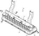
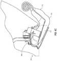
- FIG. 1Ais a perspective view of an inflatable airbag assembly, according to one embodiment of the present disclosure.
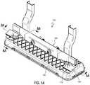
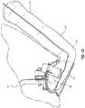
- FIG. 1Bis a perspective exploded view of the inflatable airbag assembly of FIG. 1 .
- FIG. 2is a perspective view of an inflatable airbag cushion in a rolled state and associated inflator, according to one embodiment of the present disclosure.
- FIG. 3is an elevation view of an inflatable airbag cushion laying flat.
- FIG. 4Ais an elevation view of a support strap.
- FIG. 4Bis a side view of the support strap of FIG. 4A with a fastening end folded to form a fastener.
- FIG. 4Cis a side view of the support strap of FIG. 4B with fastening end configured to orient a portion of the fastener with a transverse end portion, to form a t-shape.
- FIG. 5Ais a longitudinal cross-section view of a portion of the inflatable airbag assembly of FIG. 1A prior to deployment of an airbag cushion.
- FIG. 5Bis a longitudinal cross-section view of a portion of the inflatable airbag assembly of FIG. 5A following deployment of the airbag cushion.
- FIG. 5Cis a detail view of the fastening end of the support of the inflatable airbag assembly of FIG. 5B .
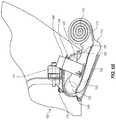
- FIG. 6Ais a side cross-section view of a portion of the inflatable airbag assembly of FIG. 1A prior to deployment of the airbag cushion.
- FIG. 6Bis a side cross-section view of a portion of the inflatable airbag assembly of FIG. 6A at a first stage of deployment of the airbag cushion.
- FIG. 6Cis a side cross-section view of a portion of the inflatable airbag assembly of FIG. 6B at a second stage of deployment of the airbag cushion.
- FIG. 6Dis a side cross-section view of a portion of the inflatable airbag assembly of FIG. 6C at a third stage of deployment of the airbag cushion.
- Occupant protection systemssuch as airbag assemblies
- airbag assembliesmay be installed at various locations within a vehicle to reduce or minimize occupant injury during a collision event.
- specific referenceis made to airbag assemblies that are designed to deploy in the direction of a knee area of an occupant seated in a vehicle seating position, although the principles discussed herein may apply to other types of airbag assemblies that are designed to cushion other portions of an occupant.
- Airbag assembliesgenerally include an airbag cushion.
- the airbag cushionis typically disposed within a housing in a packaged state (e.g., rolled, folded, and/or otherwise compressed) and may be retained in the packaged state behind a cover.
- an inflatormay be triggered, which rapidly fills the airbag cushion with inflation gas.
- the inflation gasmay cause the airbag cushion to rapidly transition from a compact packaged (i.e., un-deployed) state to an expanded or deployed state.
- the expanding airbag cushionopens an airbag cover (e.g., by tearing through a tear seam or opening a door-like structure) to exit the housing.
- the inflatormay be triggered by any suitable device or system, and the triggering may be in response to and/or influenced by one or more vehicle sensors.
- Airbag assembliescan also include a knee restraint or knee airbag to protect the hips, knees and/or lower leg of an occupant during a collision event.
- knee restraintsmay absorb at least some of the impact energy of an occupant during a collision event, especially by restraining the lower torso by means of applying a force to the knees.
- the knee restraintmay comprise an airbag cushion that contacts and cushions the knees of an occupant during a collision event.
- Some embodiments of airbag assemblies disclosed hereinmay be useful for protecting occupants seated in a front seat of a vehicle. Other embodiments of the airbag assemblies disclosed herein may be particularly useful for protecting occupants who are seated rearward of the front seats of a vehicle.
- connectionand “coupled to” are used in their ordinary sense, and are broad enough to refer to any suitable coupling or other form of interaction between two or more entities, including mechanical and fluid interaction. Two components may be coupled to each other even though they are not in direct contact with each other.
- attachment to and secured torefer to interaction between two or more entities that are in direct contact with each other and/or are separated from each other only by a fastener of any suitable variety (e.g., mounting hardware or an adhesive).
- fluid communicationis used in its ordinary sense, and is broad enough to refer to arrangements in which a fluid (e.g., a gas or a liquid) can flow from one element to another element when the elements are in fluid communication with each other.
- forward and rearwardare used with reference to the front and back of the relevant vehicle.
- an airbag cushion that deploys in a rearward directiondeploys toward the back of a vehicle.
- proximal and distalare used herein to refer to opposite locations on an airbag cushion.
- the proximal end of an airbag cushionis the end of the airbag cushion that is closest to the inflator when the airbag cushion is fully inflated.
- the distal end of an airbag cushionis the end opposite the proximal end of the airbag cushion.
- proximal and distalare with reference to a point of attachment, such as a point of attachment of the airbag cushion at an airbag assembly housing and a point of attachment of an airbag assembly at a seat back from which an airbag deploys. Specifically, “proximal” is situated toward such point of attachment and “distal” is situated away from such point of attachment.
- seatrefers to a structure within the cabin of a vehicle installed such that an occupant may be seated thereon/therein for transport within the vehicle.
- front seatrefers to any seat that is disposed immediately rearward of the instrument panel, regardless of whether disposed to either side of the vehicle, and which is disposed forward of any “back seat(s)” (defined below) which may be present in the vehicle.
- back seatrefers to any seat that is disposed rearward of the front seat(s) of a vehicle, regardless of whether the seat is the most rearward seat in the vehicle.
- back seatalso refers to any seat that is disposed rearward of other back seats.
- a “vehicle seating position”may be defined by a seat (e.g., a front passenger seat, a front driver seat, a back seat) of a vehicle.
- a vehicle seating positionmay be the position in which an occupant is generally positioned when seated in a seat of a vehicle.
- a vehicle seating positionmay also be a position in which an occupant may be seated prior to and/or during a collision event or a position in which the vehicle and/or the seat is designed to transport an occupant.
- vehiclemay refer to any vehicle, such as a car, truck, bus, airplane, etc.
- occupantgenerally refers to a person within a vehicle.
- occupantcan also include a crash test dummy within a vehicle.
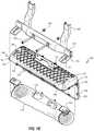
- FIGS. 1A and 1Bare a perspective view and a perspective exploded view of an airbag assembly 100 , respectively.
- the airbag assembly 100may comprise a housing 140 , a housing mounting bracket 101 , an airbag cushion 110 , and an inflator 130 .
- a support bracket 170 and/or a support strap 160may couple the airbag assembly 100 to a vehicle structure 102 .
- the airbag assembly 100may be mounted within a vehicle at or below a knee bolster portion of an instrument panel or below a steering wheel.
- the airbag assembly 100may be mounted within a vehicle at any other suitable location, such as forward of a passenger front seat to protect the head and torso of an occupant, forward of a back seat at a position below a knee level of an occupant seated in a vehicle seating position, etc.
- the housing 140comprises an integrated cover 150 , such that the housing 140 may be said to comprise a one-piece housing with a cover 150 that is attached via a hinge 149 .
- the housing 140may be a clamshell container comprising two portions (namely the cover 150 as a first portion and a container 151 as a second portion) joined via the hinge 149 .
- the housing 140may comprise a contiguous piece of a molded plastic material that forms an enclosure or container 151 with an interior space 143 .
- the container 151may comprise one or more (e.g., four) sidewalls and/or a primary wall 144 , which define the interior space 143 .
- the hinge 149may be a living hinge in the form of the same material as the cover 150 and the container 151 .
- a plurality of cover closure structures 145 , 155may secure the cover 150 to the container 151 in a closed position.
- the plurality of sidewalls of the housing 140may comprise longitudinal sidewalls 142 and lateral sidewalls 141 .
- the primary wall 144may comprise a single, linear surface, or a plurality of surfaces, as depicted in FIGS. 1A and 1B .
- the primary wall 144may span the housing and/or the interior space 143 opposite the cover 150 (or opposite an opening of the housing 140 that is closed by the cover 150 ).
- the primary wall 144may have a convex shape, giving the outside of the housing 140 (and correspondingly the interior space 143 ) a rounder shape.
- the cover closure structures 145may each comprise a protrusion that is configured to interact with a structure of complementing cover closure structures 155 .
- the cover 150may comprise a plurality of complementing cover closure structures 155 .
- the primary wall 144 of the housing 140may comprise one or more apertures 146 .
- a length of the apertures 146may be greater than a width, so as to form a narrow slot as shown in FIGS. 1A and 1B .
- the apertures 146may be oriented such that the length is parallel to the lateral sidewalls 141 of the housing 140 .
- the housing 140 and the cover 150may comprise one or more of several materials that are well known in the art, including: nylon; styrene ethylene butylene styrene block coplymers (SEBS); polyolefin monomers or co-block polymers; polypropylene monomers or co-block polymers; thermoplastic elastomer olefin (TEO); and thermoplastic polyester elastomers (TPE). These materials may be sold under the following trade names: Hytrel; Tefabloc; Tosl; Sumitomo; Tekron; Basell; Hostacom; Multiflex; and TES.
- SEBSstyrene ethylene butylene styrene block coplymers
- TEOthermoplastic elastomer olefin
- TPEthermoplastic polyester elastomers
- the housing 140may be configured to be mounted to a vehicle structure 102 .
- the vehicle structure 102may be configured as a mounting member, such as a cross car beam (CCB).
- the housing 140may be mounted to the vehicle structure using the housing mounting bracket 101 .
- the housing mounting bracket 101may be configured as an “L” bracket with a horizontal portion and a vertical portion.
- the housing mounting bracket 101may be configured to have a length that is less than the length of the housing 140 . In some embodiments, the length of housing bracket 101 may be configured to be less than 75% of the length of the housing 140 .
- the length of the housing bracket 101may be such that it is configured to be positioned between CCB support arms 105 , or other vehicle structure supporting the vehicle structure 102 .
- the housing mounting bracket 101may be mounted to the vehicle structure 102 by securing the housing mounting bracket 101 to the vehicle structure 102 using a bracket mounting structure 103 .
- the bracket mounting structure 103may comprise a mounting stem, such as a threaded bolt.
- the bracket mounting structure 103may be configured to protrude through apertures in the vehicle structure 102 , the housing mounting bracket 101 , and a complementary mounting hardware, such as nut 104 .
- the vehicle structure 102may include one or more support brackets 170 .
- the support bracket 170may comprise a vertical portion and an extending portion that is configured to conform to the shape of an outer surface of the primary wall 144 of the housing 140 .
- the lateral edges of the support bracket 170may be rolled such that additional flexural strength is provided.
- the support bracket 170may comprise a slot 171 .
- the slot 171may have a length that is greater than a width.
- the slot 171may be oriented such that the length is aligned with a longitudinal axis of the extending portion of the support bracket 170 .
- the slot 171may be configured to align with the aperture 146 of the housing 140 when the support bracket 170 is coupled to the primary wall 144 .
- the support bracket 170may be comprised of any suitable metal material, such as steel, aluminum, engineered thermoplastics or a composite, etc.
- the support bracket 170may be fixedly secured to the vehicle structure 102 using any suitable technique such as welding, adhesive, fasteners, etc.
- the support bracket 170may be removably secured to the vehicle structure 102 utilizing a mounting structure such as a threaded bolt and nut.
- the airbag assembly 100may include one or more support brackets 170 to secure to, or otherwise couple to, the vehicle structure 102 .
- the support bracket 170 and the mounting bracket 101may be formed as an integral unit wherein the integral unit is configured to be mounted to the vehicle structure 102 .
- the support bracket(s) 170may be formed integral with the housing 140 (e.g., the primary wall 144 ).
- the mounting bracketmay be formed integral with the housing 140 (e.g., the primary wall 144 ).
- the inflator 130may comprise one or more mounting structures 139 , which may comprise mounting stems, such as a threaded bolt.
- the mounting structure 139is configured to protrude through apertures in the inflatable airbag cushion 110 , the housing 140 , the housing mounting bracket 101 , and a complementary mounting hardware, such as a nut. Stated otherwise, the mounting structures 139 of the inflator 130 may secure the inflator 130 , the inflatable airbag cushion 110 and the housing 140 to the mounting bracket 101 for coupling to the vehicle structure 102 .
- the airbag 110is configured to inflate upon activation of the inflator 130 such that the inflatable airbag cushion 110 transitions from a packaged configuration (as shown in FIG. 6A ) to a deployed configuration (as shown in FIG. 6D ).
- the airbag 110may comprise an upper portion 111 , a lower portion 112 , a first face 113 , a second face 114 , and a proximal or a throat portion 115 .
- the volume of the upper portion 111may be larger than the volume of the lower portion 112 which may be larger than the throat portion 115 .
- the various faces 113 , 114 of the inflatable airbag 110define an interior inflatable void 119 , which is in fluid communication with the inflator 130 so as to receive inflation gas from the inflator 130 .
- the various faces 113 , 114 of the inflatable airbag 110may comprise separate panels of material, or may be formed from a single panel of material that is folded.
- the airbag cushion 110may comprise a woven nylon fabric.
- the upper portion 111 of the airbag cushion 110is the portion of the airbag that is closest to the headliner of a vehicle when the airbag cushion 110 is in a deployed state.
- the lower portion 112is below the upper portion 111 when the inflatable airbag cushion 110 is in a deployed state, and is closest to a floor of the vehicle.
- the term “lower portion”is not necessarily limited to the portion of inflatable airbag cushion 110 that is below a horizontal medial plane of the inflatable airbag, but may include less than half, more than half or exactly half of the bottom portion of the inflatable airbag cushion 110 .
- upper portionis not necessarily limited to the portion of inflatable airbag cushion 110 that is above a horizontal medial plane of the inflatable airbag cushion 110 , but may include less than half, more than half or exactly half of the top portion of the inflatable airbag cushion 110 .
- the airbag cushion 110may comprise an attachment position 116 located on a lateral portion adjacent the throat portion 115 .
- the attachment position 116may be configured to extend outward from the airbag cushion 110 .
- the attachment position 116may extend from the first face 113 and/or the second face 114 .
- the attachment position 116may be integral with the first face 113 and/or the second face 114 .
- the attachment position 116may form a portion of selvage of the airbag cushion 110 .
- the attachment position 116may be attached to the first face 113 and/or the second face 114 using any suitable technique, such as sewing, gluing, etc.
- the support strap 160may be configured to direct the movement of the airbag cushion 110 in a predetermined direction or deployment trajectory.
- the support strap 160may provide resistance to the airbag cushion during deployment, wherein the strap resists the movement of the airbag cushion 110 in a vehicle forward and downward direction.
- the airbag cushion 110is directed by the support strap 160 during deployment in a car rearward and upward direction.
- the support strap 160may comprise a strap portion 161 , a first end 162 or secured end, and a second end 163 or fastening end.
- the support strap 160may comprise a woven material, such as a woven nylon material. Other materials, such as woven polyester, woven polypropylene, natural or other synthetic fibers in the form of webbing, fabric or rope with suitable tensile and elongation properties to withstand the air bag loads, etc., may be utilized and are contemplated within the scope of the disclosure.
- the support strapmay have a length greater than a width.
- the second end 163 or fastening end of the support strap 160is configured to pass through the aperture 146 and slot 171 .
- the second end 163may include a fastener 168 . In the illustrated embodiment of FIGS.
- the fastener 168comprises folding and securing of the folds to configure the second end as a “T” shape with a transverse portion 164 oriented perpendicular to the strap portion 161 .
- the transverse portion 164may be configured with a first arm 165 and a second arm 166 .
- the strap portion 161may be secured to the middle of the transverse portion 164 using a sewn stitch.
- the first arm 165 and the second arm 166may comprise a plurality of folded layers of the woven material.
- the first end 162 or secured end of the support strap 160may be secured to the attachment position 116 of the airbag cushion 110 using a box stitch sewing technique such that a width of the support strap 160 is orthogonal to a width of airbag cushion 110 .
- the support strapmay be secured to the attachment position 116 using any suitable sewing technique.
- the support strapmay be secured to the first surface 113 and/or the second surface 114 at any suitable location.
- FIGS. 5A-5Cdepict the airbag assembly 100 from a longitudinal cross-section view.
- FIG. 5Adepicts the strap portion 161 passing through the aperture 146 and the slot 171 such that the transverse portion 164 lays flat on the support bracket 170 prior to airbag cushion 110 deployment.
- FIG. 5Bwhen the airbag cushion 110 is deployed, tension or a downward force is applied to the support strap 160 such that the transverse portion 164 folds upward.
- the first arm 165 and the second arm 166are oriented vertically such that a combined thickness “T” of the first arm 165 and the second arm 166 is greater than the width “W” of the aperture 146 and the slot 171 as illustrated in FIG. 5C .
- the thickness “T”prevents the support strap 160 from being pulled into the housing 140 .
- the support strap 160directs deployment of the airbag cushion 110 in a predetermined or deployment trajectory.
- the airbag assembly 100may be configured to be lightweight. In one embodiment, the airbag assembly may be less than 750 grams. In other embodiments, the airbag assembly 100 may have a weight in the range 500 grams to 1000 grams. In other embodiments, the airbag assembly 100 may have a weight in the range 600 grams to 900 grams. In other embodiments, the airbag assembly 100 may have a weight in the range 700 grams to 800 grams.
- FIG. 6Adepicts the airbag assembly 100 from a cross-sectional side view, wherein the airbag assembly 100 has been mounted within a vehicle 10 .
- the airbag assembly 100may comprise the housing mounting bracket 101 , the inflatable airbag cushion 110 , the inflator 130 , the housing 140 , the support bracket 170 , and the support strap 160 .
- FIG. 6Adepicts the airbag assembly 100 in the packaged configuration prior to deployment of the airbag cushion 110 .
- FIG. 6Bis a cross-sectional side view of the airbag assembly 100 of FIG. 6A , wherein airbag cushion 110 is depicted in a first stage of deployment.
- the airbag cushion 110is configured to become inflated upon activation of inflator 130 such that the inflatable airbag cushion 110 transitions from the packaged configuration to the first deployed stage configuration.
- the cover 150has rotated about the hinge 149 such that the airbag cushion 110 can exit the interior space 143 .
- the force of inflation gas inflating the airbag cushion 110may apply pressure to the cover 150 , thereby forcing the cover 150 to open.
- the cover 150 closure structure 155has been released from closure structure 145 .
- the force of the inflation gas inflating the airbag cushion 110has applied tension or a downward force to the support strap 160 such that the transverse member 164 has folded upward.
- the thickness of the transverse member 164 in this configurationis increased such that the thickness is greater than the width of the slot 171 of the support bracket 170 .
- the support strap 160is prevented from pulling through the slot 171 into the interior space 143 .
- the airbag cushion 110is supported by the support strap 160 such that the support strap 160 directs the trajectory of the airbag cushion deployment initially downward to open the cover 150 and then rearwardly as depicted in FIG. 6B .
- the support strap 160prevents the airbag cushion 110 from deploying forwardly. Additionally, the support strap 160 has supported the airbag cushion 110 wherein expansion of the throat portion 115 of the airbag cushion 110 is restricted from expanding. The restricted throat portion 115 allows the inflation gas to be directed into the lower portion 112 and the upper portion 111 of the airbag cushion 110 .
- FIG. 6Cis a cross-sectional side view of the airbag assembly 100 in a second stage of deployment.
- the force of inflation gas inflating the airbag cushion 110has filled the lower portion 112 and the airbag cushion 110 is deploying upwardly and rearwardly.
- the airbag cushion 110is supported by the support strap 160 such that the support strap 160 directs the trajectory of the airbag cushion deployment upwardly and rearwardly and restricts expansion of the throat portion 115 .
- the support strap 160continues to limit the airbag cushion 110 from deploying forwardly.
- FIG. 6Dis a cross-sectional side view of the airbag assembly 100 in a third stage of deployment.
- the force of inflation gas inflating the airbag cushion 110has filled the lower portion 112 and the upper portion 111 , wherein the airbag cushion 110 is deployed upwardly and rearwardly to its full extent.
- the airbag cushion 110is supported by the support strap 160 such that the support strap 160 directs the trajectory of the airbag cushion deployment upwardly and rearwardly and restricts expansion of the throat portion 115 .
- the support strap 160continues to prevent the airbag cushion 110 from deploying forwardly.
- the deployed airbag cushion 110is positioned forward of the front seat and/or the back seat.
- the deployed airbag cushion 110may be configured to protect an occupant from lower extremity injuries, such as hip, femur, knee, and/or lower leg injuries.
- Any methods disclosed hereininclude one or more steps or actions for performing the described method.
- the method steps and/or actionsmay be interchanged with one another.
- the order and/or use of specific steps and/or actionsmay be modified.
- sub-routines or only a portion of a method described hereinmay be a separate method within the scope of this disclosure. Stated otherwise, some methods may include only a portion of the steps described in a more detailed method.
Landscapes
- Engineering & Computer Science (AREA)
- Mechanical Engineering (AREA)
- Air Bags (AREA)
Abstract
Description
Claims (29)
Priority Applications (1)
| Application Number | Priority Date | Filing Date | Title |
|---|---|---|---|
| US15/809,723US10696266B2 (en) | 2017-11-10 | 2017-11-10 | Inflatable knee airbag assemblies |
Applications Claiming Priority (1)
| Application Number | Priority Date | Filing Date | Title |
|---|---|---|---|
| US15/809,723US10696266B2 (en) | 2017-11-10 | 2017-11-10 | Inflatable knee airbag assemblies |
Publications (2)
| Publication Number | Publication Date |
|---|---|
| US20190143931A1 US20190143931A1 (en) | 2019-05-16 |
| US10696266B2true US10696266B2 (en) | 2020-06-30 |
Family
ID=66431679
Family Applications (1)
| Application Number | Title | Priority Date | Filing Date |
|---|---|---|---|
| US15/809,723Active2038-02-28US10696266B2 (en) | 2017-11-10 | 2017-11-10 | Inflatable knee airbag assemblies |
Country Status (1)
| Country | Link |
|---|---|
| US (1) | US10696266B2 (en) |
Cited By (4)
| Publication number | Priority date | Publication date | Assignee | Title |
|---|---|---|---|---|
| US20210316693A1 (en)* | 2020-04-08 | 2021-10-14 | Autoliv Asp, Inc. | Bi-directional airbag cushion wrappers and related airbag assemblies and methods |
| US11541838B2 (en)* | 2017-10-20 | 2023-01-03 | Dalphi Metal Espana S.A. | Cover of an airbag for a vehicle occupant restraint system, and method for packing an airbag in a cover |
| US11560111B2 (en) | 2019-03-29 | 2023-01-24 | Mcpp Innovation Llc | All TPO airbag assemblies |
| US20250242774A1 (en)* | 2021-10-25 | 2025-07-31 | Hyundai Mobis Co., Ltd. | Knee air bag |
Families Citing this family (2)
| Publication number | Priority date | Publication date | Assignee | Title |
|---|---|---|---|---|
| CN112622800A (en)* | 2020-12-23 | 2021-04-09 | 奇瑞汽车股份有限公司 | Knee airbag structure and vehicle |
| KR102751371B1 (en)* | 2022-08-22 | 2025-01-10 | 아시모리코리아(주) | Knee airbag apparatus for vehicle |
Citations (156)
| Publication number | Priority date | Publication date | Assignee | Title |
|---|---|---|---|---|
| US3858822A (en) | 1972-02-14 | 1975-01-07 | True Temper Corp | Spinning reel |
| US3904222A (en) | 1973-12-03 | 1975-09-09 | Gen Motors Corp | Occupant restraint system |
| US3966227A (en) | 1974-10-24 | 1976-06-29 | General Motors Corporation | Cover assembly for an occupant restraint system |
| US4290627A (en) | 1979-12-03 | 1981-09-22 | General Motors Corporation | L-shaped inflatable restraint cushion |
| US5338061A (en) | 1992-04-08 | 1994-08-16 | Daicel Chemical Industries, Ltd. | Air bag having double-wall construction |
| US5344184A (en) | 1993-12-21 | 1994-09-06 | Trw Vehicle Safety Systems Inc. | Method and apparatus for restraining a vehicle occupant |
| US5427410A (en) | 1993-06-07 | 1995-06-27 | Takata Corporation | Air bag with large size and small volume |
| US5460400A (en) | 1994-05-20 | 1995-10-24 | Takata, Inc. | Passenger-side air bag module with improved assembly features |
| US5529337A (en) | 1993-12-08 | 1996-06-25 | Takata Corporation | Air bag device |
| US5669627A (en) | 1996-07-25 | 1997-09-23 | Morton International, Inc. | Side impact airbag module with extruded cover |
| US5690354A (en) | 1996-03-19 | 1997-11-25 | General Motors Corporation | Air bag module |
| US5765867A (en) | 1996-05-03 | 1998-06-16 | Alliedsignal Inc. | Air bag with externally mounted tether |
| US5772239A (en) | 1996-06-24 | 1998-06-30 | Takata, Inc. | Airbag sub-module having fabric envelope with horn switch |
| US5803487A (en) | 1997-02-19 | 1998-09-08 | Alliedsignal Inc. | Air bag apparatus for vehicle |
| US5810390A (en) | 1996-12-09 | 1998-09-22 | Morton International, Inc. | Module case for side impact airbag module |
| US5823566A (en) | 1996-10-16 | 1998-10-20 | Alliedsignal Inc. | Air bag module with deployment flap |
| US5845935A (en) | 1997-03-07 | 1998-12-08 | Morton International, Inc. | Side airbag module |
| US5927748A (en) | 1997-06-26 | 1999-07-27 | O'driscoll; Peter | Multi-stage inflatable bag for vehicular safety systems |
| US6010147A (en) | 1997-12-09 | 2000-01-04 | Rover Group Limited | Motor vehicle and a motor vehicle airbag module |
| US6059312A (en) | 1998-10-16 | 2000-05-09 | Breed Automotive Technology, Inc. | Dual chamber airbag |
| US6135495A (en) | 1997-12-10 | 2000-10-24 | Rover Group Limited | Motor vehicle and a motor vehicle airbag module |
| US6155595A (en) | 1998-04-23 | 2000-12-05 | Trw Occupant Restraint Systems Gmbh & Co. Kg | Knee protection device for vehicle occupants |
| US6213496B1 (en) | 1998-03-13 | 2001-04-10 | Takata Corporation | Airbag device with inner and outer bags |
| US6217059B1 (en) | 1999-08-16 | 2001-04-17 | Trw Inc. | Apparatus for helping to protect a vehicle occupant's legs |
| US6224129B1 (en) | 2000-07-11 | 2001-05-01 | Illinois Tool Works Inc. | Car seat tether anchor and system |
| US6254121B1 (en) | 1998-12-14 | 2001-07-03 | Breed Automotive Technology, Inc. | Chambered driver side air bag and module attachment method |
| US20010007391A1 (en) | 1997-12-09 | 2001-07-12 | Toyota Jidosha Kabushiki Kaisha | Air bag apparatus for passenger seat |
| US6299205B1 (en) | 1998-08-18 | 2001-10-09 | Milliken & Company | Vehicle restraint system comprising an airbag having a looped pocket for inflation canister disposition |
| WO2002004262A1 (en) | 2000-07-07 | 2002-01-17 | Toyoda Gosei Co., Ltd. | Air bag device for knee protection |
| US6364348B1 (en) | 2000-02-01 | 2002-04-02 | Delphi Automotive Systems Sungwoo Corp. | Side airbag system and method for manufacturing the same |
| US20020044819A1 (en) | 2000-11-10 | 2002-04-18 | Shamoon Ellis N. | Case binder with living hinge |
| US6431583B1 (en) | 2001-02-28 | 2002-08-13 | Autoliv Asp, Inc. | Inflatable knee bolster with external tethering |
| US6454296B1 (en) | 2000-11-22 | 2002-09-24 | Delphi Technologies, Inc. | Side air bag for roll-over restraint |
| US6464255B1 (en) | 2001-05-10 | 2002-10-15 | Patent Holding Company | Knee bolster airbag system |
| US20020149187A1 (en) | 2001-04-11 | 2002-10-17 | Holtz Kimberlee D. | Soft-surface inflatable knee bolster airbag |
| US6474686B1 (en) | 2000-05-29 | 2002-11-05 | Honda Giken Kogyo Kabushiki Kaisha | Air bag device |
| US20020171231A1 (en) | 2001-05-21 | 2002-11-21 | Masahiro Takimoto | Knee protecting airbag device |
| US20020180187A1 (en) | 2001-05-30 | 2002-12-05 | Takata Corporation | Vehicle occupant protection device |
| US6494484B2 (en) | 1999-04-23 | 2002-12-17 | Milliken & Company | Polygon-shaped air bag |
| US20030034637A1 (en) | 2000-07-07 | 2003-02-20 | Yunzhang Wang | Multiple chamber airbags and methods |
| US6588793B2 (en) | 2001-09-19 | 2003-07-08 | Autoliv Asp, Inc. | Thin airbag module design for overhead applications |
| US6631920B1 (en) | 1999-02-18 | 2003-10-14 | Delphi Technologies, Inc. | Airbag module |
| US20030209888A1 (en) | 2002-05-13 | 2003-11-13 | Lear Corporation | Air bag assembly |
| US6648371B2 (en)* | 2001-07-12 | 2003-11-18 | Delphi Technologies, Inc. | Variable venting air bag assembly |
| US6655711B1 (en) | 2000-10-27 | 2003-12-02 | Textron Automotive Company, Inc. | Air bag cover assembly |
| US6682093B2 (en) | 2000-12-19 | 2004-01-27 | Toyoda Gosei Co., Ltd. | Air bag device |
| US6685217B2 (en) | 2001-05-21 | 2004-02-03 | Takata Corporation | Leg protection device for vehicle occupants |
| US6746045B2 (en)* | 2002-04-05 | 2004-06-08 | Ford Global Technologies, Llc | Air bag inflator gas venting system |
| US6752417B2 (en) | 2001-05-21 | 2004-06-22 | Toyoda Gosei Co., Ltd. | Knee protecting airbag device |
| US20050001412A1 (en) | 2003-07-01 | 2005-01-06 | Schneider David W. | Overhead airbad with external tether |
| US6846005B2 (en) | 2002-12-09 | 2005-01-25 | Key Safety Systems, Inc. | Air bag cushion and module |
| US20050057028A1 (en) | 2001-12-10 | 2005-03-17 | Tatsuya Hayakawa | Occupant knee protection system for vehicle and inflating and deploying method |
| US20050062265A1 (en) | 2003-09-24 | 2005-03-24 | Toyoda Gosei Co., Ltd. | Knee protection airbag apparatus |
| US6877765B2 (en) | 2002-09-11 | 2005-04-12 | Autoliv Asp, Inc. | Load path control for inflatable airbag |
| US6913280B2 (en) | 2002-11-12 | 2005-07-05 | Autoliv Asp, Inc. | Overhead airbag deployment apparatus and method |
| US20050151351A1 (en) | 2004-01-12 | 2005-07-14 | Enders Mark L. | Fabric knee airbag for high internal pressures |
| US20050194767A1 (en) | 2004-03-05 | 2005-09-08 | Trw Automotive Gmbh | Gas bag module, in particular for a knee gas bag |
| US20050194771A1 (en) | 2004-03-02 | 2005-09-08 | Clark Marcus T. | Expanding airbag inflator housing |
| US6945557B2 (en) | 2001-11-09 | 2005-09-20 | Toyoda Gosei Co., Ltd. | Knee protecting airbag device |
| US20050212275A1 (en) | 2004-03-23 | 2005-09-29 | Takata Corporation | Airbag apparatus and method of folding airbag |
| US20050230939A1 (en) | 2004-04-20 | 2005-10-20 | Takata Corporation | Knee-bag module |
| US6959944B2 (en) | 2002-04-11 | 2005-11-01 | Toyoda Gosei Co., Ltd. | Airbag apparatus |
| US6962366B2 (en) | 2002-06-11 | 2005-11-08 | Honda Giken Kogyo Kabushiki Kaisha | Air bag device |
| US7000945B2 (en) | 2003-09-10 | 2006-02-21 | Trw Vehicle Safety Systems Inc. | Inflatable windshield curtain |
| US7000947B2 (en) | 2000-02-25 | 2006-02-21 | Takata Corporation | Airbag device |
| US7011337B2 (en)* | 2001-06-11 | 2006-03-14 | Honda Giken Kogyo Kabushiki Kaisha | Occupant restraint system |
| US7017945B2 (en)* | 2002-05-17 | 2006-03-28 | Depottey Timothy | Active venting apparatus and method for airbag systems |
| US7029026B2 (en) | 2002-09-13 | 2006-04-18 | Toyoda Gosei Co., Ltd. | Knee protection airbag apparatus |
| US7055851B2 (en) | 2001-11-20 | 2006-06-06 | Toyoda Gosei Co., Ltd. | Knee protecting airbag device |
| US7083188B2 (en)* | 2003-11-13 | 2006-08-01 | Autoliv Asp, Inc. | Tearable retention apparatus and method for an airbag cushion |
| US20060192370A1 (en)* | 2005-02-28 | 2006-08-31 | Takata Corporation | Passenger restraint system |
| US20060244247A1 (en)* | 2005-04-29 | 2006-11-02 | Trw Automotive Gmbh | Gas bag module |
| US7131664B1 (en) | 2005-10-17 | 2006-11-07 | Key Safety Systems, Inc. | Airbag with a strategically placed recess |
| US20060279073A1 (en) | 2005-05-18 | 2006-12-14 | Toyoda Gosei Co., Ltd. | Airbag device |
| US7156418B2 (en) | 2003-07-31 | 2007-01-02 | Toyoda Gosei Co., Ltd. | Method for folding airbag, airbag apparatus, and airbag |
| US7175195B2 (en) | 2002-12-25 | 2007-02-13 | Toyoda Gosei Co., Ltd. | Occupant protection device |
| US7182365B2 (en) | 2000-07-07 | 2007-02-27 | Toyoda Gosei Co., Ltd. | Air bag device for knee protection |
| US7185912B2 (en) | 2002-07-18 | 2007-03-06 | Toyoda Gosei Co., Ltd. | Knee protection airbag device |
| US20070057487A1 (en) | 2005-09-12 | 2007-03-15 | Hyundai Mobis Co., Ltd. | Air bag module |
| US7195275B2 (en) | 2005-02-09 | 2007-03-27 | Takata Corporation | Airbag and airbag apparatus |
| US7195280B2 (en) | 2003-11-20 | 2007-03-27 | Autoliv Asp, Inc. | High internal pressure fabric airbag with exposed inflator |
| US20070120346A1 (en) | 2005-11-23 | 2007-05-31 | Hyundai Mobis Co., Ltd. | Air bag module |
| US7226077B2 (en) | 2003-09-09 | 2007-06-05 | Takata Corporation | Airbag, airbag assembly and airbag device |
| US20070170709A1 (en)* | 2006-01-20 | 2007-07-26 | Trw Vehicle Safety Systems Inc. | Air bag module with vent flow control |
| US7261318B2 (en) | 2003-12-01 | 2007-08-28 | Autoliv Asp, Inc. | Knee airbag and glove box assembly |
| US20070200321A1 (en) | 2006-02-24 | 2007-08-30 | Frank Heitplatz | Knee Airbag |
| US7281734B2 (en) | 2003-01-23 | 2007-10-16 | Takata Corporation | Airbag and airbag system |
| US20070246920A1 (en) | 2006-04-24 | 2007-10-25 | Trw Automotive Gmbh | Vehicle occupant restraint device comprising a gas bag |
| US20070267852A1 (en) | 2006-05-18 | 2007-11-22 | Enders Mark L | Knee airbag and restraint system for suppressing deployment of head/torso airbag |
| US7314228B2 (en) | 2004-07-14 | 2008-01-01 | Toyoda Gosei Co., Ltd. | Airbag device |
| US7314230B2 (en) | 2003-12-19 | 2008-01-01 | Takata Corporation | Kneebag and occupant leg protection system |
| DE202006014012U1 (en) | 2006-09-08 | 2008-01-17 | Autoliv Development Ab | side airbags |
| US20080048418A1 (en) | 2006-08-23 | 2008-02-28 | Jim Remley | Self-closing leadwire clip and airbag housing |
| US7347444B2 (en) | 2004-05-06 | 2008-03-25 | Autoliv Asp, Inc. | Inflatable airbag with overlapping chamber |
| US7354064B2 (en)* | 2005-02-01 | 2008-04-08 | Key Safety Systems, Inc. | Active tether air bag module |
| US7374201B2 (en) | 2003-08-22 | 2008-05-20 | Mollertech | Enclosure part for automotive vehicles, with a panel suitable for concealing an inflatable airbag |
| US7374202B2 (en) | 2003-08-14 | 2008-05-20 | Hyundai Mobis Co., Ltd. | Assembly structure of airbag case |
| US7377546B2 (en)* | 2002-09-16 | 2008-05-27 | Trw Vehicle Safety Systems, Inc. | Air bag module with vent controlled by tether |
| US7380813B2 (en) | 2004-01-16 | 2008-06-03 | Lisa Dräxlmaier GmbH | Flexible airbag flap |
| US7384065B2 (en) | 2001-12-06 | 2008-06-10 | Toyoda Gosei Co., Ltd. | Knee protection airbag device |
| US7387311B2 (en) | 2002-12-12 | 2008-06-17 | Takata Corporation | Module cover for airbag apparatus |
| US20080157509A1 (en) | 2004-02-27 | 2008-07-03 | Takata Corporation | Knee-bag and occupant leg protection apparatus |
| US7396044B2 (en) | 2005-07-11 | 2008-07-08 | Tk Holdings Inc. | Deployment control device for air bag |
| US20080217892A1 (en) | 2007-03-05 | 2008-09-11 | Tk Holdings Inc. | Airbag module with deployment control flap |
| US20080238048A1 (en) | 2007-04-02 | 2008-10-02 | Toyoda Gosei Co., Ltd. | Knee-protecting airbag apparatus |
| US7434837B2 (en) | 2004-11-09 | 2008-10-14 | Toyoda Gosei Co., Ltd. | Knee-protecting airbag device |
| US7448646B2 (en)* | 2005-11-04 | 2008-11-11 | Ford Global Technologies, Llc | Airbag system for out-of-position occupant protection and adaptive venting |
| US7487994B2 (en) | 2004-02-02 | 2009-02-10 | Toyoda Gosei Co., Ltd. | Airbag device for front passenger's seat |
| US20090045607A1 (en) | 2007-08-10 | 2009-02-19 | Toyoda Gosei., Ltd. | Airbag apparatus |
| US20090058052A1 (en) | 2007-08-27 | 2009-03-05 | Key Safety Systems, Inc. | Knee Air Bag Module and Method of Assembly |
| US20090058048A1 (en) | 2007-08-31 | 2009-03-05 | Toyoda Gosei Co., Ltd. | Wrapping sheet |
| US7510212B2 (en)* | 2007-03-26 | 2009-03-31 | Autoliv Asp, Inc. | Airbag tether cutter and vent closer |
| US20090085333A1 (en) | 2007-09-27 | 2009-04-02 | Toyoda Gosei Co., Ltd. | Airbag for knee protection |
| US20090134611A1 (en) | 2007-11-02 | 2009-05-28 | Tk Holdings Inc. | Knee airbag |
| US20090146400A1 (en) | 2007-12-07 | 2009-06-11 | Gm Global Technology Operations, Inc. | Knee Airbag Apparatus for a Motorized Vehicle |
| US20090152842A1 (en) | 2007-12-13 | 2009-06-18 | Autoliv Asp, Inc. | Airbag lateral flap |
| US20090152847A1 (en) | 2007-12-18 | 2009-06-18 | Delphi Korea Corporation | Knee airbag and method of folding the same |
| US7549672B2 (en) | 2004-05-27 | 2009-06-23 | Toyoda Gosei Co., Ltd. | Side airbag device |
| US7566074B2 (en) | 2002-02-20 | 2009-07-28 | Delphi Technologies, Inc. | Apparatus and method for controlling an inflatable cushion |
| US7568724B2 (en) | 2006-09-22 | 2009-08-04 | Autoliv Asp, Inc. | Airbag cover with retaining channel |
| US7568730B2 (en) | 2005-12-16 | 2009-08-04 | Hyundai Mobis Co., Ltd. | Passenger air bag module |
| US20090212541A1 (en) | 2008-02-25 | 2009-08-27 | Autoliv Development Ab | Assembly with an instrument panel for a motor vehicle and a knee airbag |
| US20090242308A1 (en) | 2008-03-27 | 2009-10-01 | Toyoda Gosei Co., Ltd. | Pedestrian protection system |
| US7631894B2 (en) | 2005-07-25 | 2009-12-15 | Takata Corporation | Airbag device |
| DE102008029810A1 (en) | 2008-06-24 | 2009-12-31 | Trw Automotive Gmbh | Flat airbag i.e. knee airbag folding method for use in motor vehicle, involves folding discharging section of air bag, and rolling up inflating section of gas bag in rolling direction by folded discharging section |
| US20100025973A1 (en) | 2005-10-07 | 2010-02-04 | Delphi Technologies, Inc. | Automobile side airbag guide plate |
| US7658409B2 (en) | 2007-05-21 | 2010-02-09 | Key Safety Systems, Inc | Driver side air bag |
| US7658408B2 (en) | 2006-08-03 | 2010-02-09 | Toyoda Gosei Co. Ltd. | Airbag assembly |
| US7690683B2 (en)* | 2007-03-26 | 2010-04-06 | Autoliv Asp, Inc. | Airbag with automatic vent closer |
| US7695013B2 (en) | 2008-05-20 | 2010-04-13 | Tk Holdings Inc. | Deployment control device for airbag |
| US20100090445A1 (en) | 2008-10-14 | 2010-04-15 | Autoliv Asp, Inc. | Mounting bracket for tether release mechanism |
| US7712769B2 (en) | 2006-09-13 | 2010-05-11 | Takata Corporation | Airbag device |
| US7717460B2 (en) | 2004-12-02 | 2010-05-18 | Takata-Petri Ag | Airbag |
| US7731233B2 (en)* | 2007-04-12 | 2010-06-08 | Autoliv Asp, Inc. | Airbag cushion with vent tube |
| US7748739B2 (en) | 2006-06-27 | 2010-07-06 | Autoliv Asp, Inc. | Device for protecting an inflatable element |
| US7753405B2 (en) | 2007-01-24 | 2010-07-13 | Toyoda Gosei Co., Ltd. | Air bag system |
| US7753407B2 (en) | 2007-09-20 | 2010-07-13 | Takata Corporation | Side airbag apparatus with side airbag cover |
| US7775549B2 (en)* | 2005-03-22 | 2010-08-17 | Takata - Petri Ag | Roof-lining module |
| US7793973B2 (en) | 2002-03-11 | 2010-09-14 | Toyoda Gosei Co., Ltd. | Side airbag apparatus |
| US7819419B2 (en) | 2003-01-20 | 2010-10-26 | Toyota Jidosha Kabushiki Kaisha | Occupant protection device |
| US20100270779A1 (en) | 2009-04-27 | 2010-10-28 | Autoliv Asp, Inc. | Inflatable knee airbags and internal tethers produced from single panels of material |
| US20100270782A1 (en) | 2009-04-27 | 2010-10-28 | Autoliv Asp, Inc. | Inflatable knee airbag assemblies with bag straps for wrapping the airbags and optimizing deployment |
| US20100270775A1 (en) | 2009-04-27 | 2010-10-28 | Autoliv Asp, Inc. | Knee airbag assemblies configured for inflator insertion and inflator-mediated coupling to an airbag housing |
| WO2011008916A1 (en) | 2009-07-16 | 2011-01-20 | Autoliv Asp, Inc. | Inflatable knee airbag having two chambers separated by an internal tether |
| US20110101660A1 (en) | 2009-11-03 | 2011-05-05 | Autoliv Asp, Inc. | Low-mount inflatable knee airbags having serial chambers |
| US20110148077A1 (en) | 2009-12-22 | 2011-06-23 | Autoliv Asp, Inc. | Inflatable airbag assembly with an integral cover |
| US20120025496A1 (en) | 2009-04-27 | 2012-02-02 | Autoliv Asp, Inc. | Knee airbag assemblies and related methods |
| US20120049488A1 (en) | 2010-08-31 | 2012-03-01 | Autoliv Asp, Inc. | Covers for inflatable knee airbag housings |
| US20120049497A1 (en) | 2010-08-31 | 2012-03-01 | Autoliv Asp, Inc. | Inflatable knee airbag assemblies with articulating housings |
| US8186714B2 (en)* | 2009-10-29 | 2012-05-29 | Autoliv Asp, Inc. | Inflatable airbag assembly with an airbag housing vent panel |
| US8353525B2 (en)* | 2011-03-23 | 2013-01-15 | Autoliv Asp, Inc. | Pyrotechnic tether release assembly with a break-away piston for inflatable airbags |
| US8388021B2 (en)* | 2008-09-29 | 2013-03-05 | Toyota Jidosha Kabushiki Kaisha | Passenger seat airbag apparatus |
| US8500166B2 (en)* | 2011-08-10 | 2013-08-06 | Takata Corporation | Strap retention device and airbag device |
| US8505963B1 (en)* | 2012-02-24 | 2013-08-13 | Autoliv Asp, Inc. | Airbag assemblies with strap clamps |
| WO2017137387A1 (en) | 2016-02-09 | 2017-08-17 | Trw Automotive Gmbh | Knee air bag module |
| US10457240B2 (en)* | 2016-11-04 | 2019-10-29 | Magnesium Products Of America | Glove box rail with integrated airbag support |
- 2017
- 2017-11-10USUS15/809,723patent/US10696266B2/enactiveActive
Patent Citations (180)
| Publication number | Priority date | Publication date | Assignee | Title |
|---|---|---|---|---|
| US3858822A (en) | 1972-02-14 | 1975-01-07 | True Temper Corp | Spinning reel |
| US3904222A (en) | 1973-12-03 | 1975-09-09 | Gen Motors Corp | Occupant restraint system |
| US3966227A (en) | 1974-10-24 | 1976-06-29 | General Motors Corporation | Cover assembly for an occupant restraint system |
| US4290627A (en) | 1979-12-03 | 1981-09-22 | General Motors Corporation | L-shaped inflatable restraint cushion |
| US5338061A (en) | 1992-04-08 | 1994-08-16 | Daicel Chemical Industries, Ltd. | Air bag having double-wall construction |
| US5427410A (en) | 1993-06-07 | 1995-06-27 | Takata Corporation | Air bag with large size and small volume |
| US5529337A (en) | 1993-12-08 | 1996-06-25 | Takata Corporation | Air bag device |
| US5344184A (en) | 1993-12-21 | 1994-09-06 | Trw Vehicle Safety Systems Inc. | Method and apparatus for restraining a vehicle occupant |
| US5460400A (en) | 1994-05-20 | 1995-10-24 | Takata, Inc. | Passenger-side air bag module with improved assembly features |
| US5690354A (en) | 1996-03-19 | 1997-11-25 | General Motors Corporation | Air bag module |
| US5765867A (en) | 1996-05-03 | 1998-06-16 | Alliedsignal Inc. | Air bag with externally mounted tether |
| US5772239A (en) | 1996-06-24 | 1998-06-30 | Takata, Inc. | Airbag sub-module having fabric envelope with horn switch |
| US5669627A (en) | 1996-07-25 | 1997-09-23 | Morton International, Inc. | Side impact airbag module with extruded cover |
| US5823566A (en) | 1996-10-16 | 1998-10-20 | Alliedsignal Inc. | Air bag module with deployment flap |
| US5810390A (en) | 1996-12-09 | 1998-09-22 | Morton International, Inc. | Module case for side impact airbag module |
| US5803487A (en) | 1997-02-19 | 1998-09-08 | Alliedsignal Inc. | Air bag apparatus for vehicle |
| US5845935A (en) | 1997-03-07 | 1998-12-08 | Morton International, Inc. | Side airbag module |
| US5927748A (en) | 1997-06-26 | 1999-07-27 | O'driscoll; Peter | Multi-stage inflatable bag for vehicular safety systems |
| US20010007391A1 (en) | 1997-12-09 | 2001-07-12 | Toyota Jidosha Kabushiki Kaisha | Air bag apparatus for passenger seat |
| US6010147A (en) | 1997-12-09 | 2000-01-04 | Rover Group Limited | Motor vehicle and a motor vehicle airbag module |
| US6135495A (en) | 1997-12-10 | 2000-10-24 | Rover Group Limited | Motor vehicle and a motor vehicle airbag module |
| US6213496B1 (en) | 1998-03-13 | 2001-04-10 | Takata Corporation | Airbag device with inner and outer bags |
| US6155595A (en) | 1998-04-23 | 2000-12-05 | Trw Occupant Restraint Systems Gmbh & Co. Kg | Knee protection device for vehicle occupants |
| US6299205B1 (en) | 1998-08-18 | 2001-10-09 | Milliken & Company | Vehicle restraint system comprising an airbag having a looped pocket for inflation canister disposition |
| US6059312A (en) | 1998-10-16 | 2000-05-09 | Breed Automotive Technology, Inc. | Dual chamber airbag |
| US6254121B1 (en) | 1998-12-14 | 2001-07-03 | Breed Automotive Technology, Inc. | Chambered driver side air bag and module attachment method |
| US6631920B1 (en) | 1999-02-18 | 2003-10-14 | Delphi Technologies, Inc. | Airbag module |
| US6494484B2 (en) | 1999-04-23 | 2002-12-17 | Milliken & Company | Polygon-shaped air bag |
| US6217059B1 (en) | 1999-08-16 | 2001-04-17 | Trw Inc. | Apparatus for helping to protect a vehicle occupant's legs |
| US6364348B1 (en) | 2000-02-01 | 2002-04-02 | Delphi Automotive Systems Sungwoo Corp. | Side airbag system and method for manufacturing the same |
| US7000947B2 (en) | 2000-02-25 | 2006-02-21 | Takata Corporation | Airbag device |
| US6474686B1 (en) | 2000-05-29 | 2002-11-05 | Honda Giken Kogyo Kabushiki Kaisha | Air bag device |
| US7370881B2 (en) | 2000-07-07 | 2008-05-13 | Toyoda Gosei Co., Ltd. | Knee protecting airbag device |
| US7182365B2 (en) | 2000-07-07 | 2007-02-27 | Toyoda Gosei Co., Ltd. | Air bag device for knee protection |
| WO2002004262A1 (en) | 2000-07-07 | 2002-01-17 | Toyoda Gosei Co., Ltd. | Air bag device for knee protection |
| US6962363B2 (en) | 2000-07-07 | 2005-11-08 | Milliken & Company | Multiple chamber airbags and methods |
| US20030034637A1 (en) | 2000-07-07 | 2003-02-20 | Yunzhang Wang | Multiple chamber airbags and methods |
| US7878540B2 (en) | 2000-07-07 | 2011-02-01 | Toyoda Gosei Co., Ltd. | Knee protecting airbag device |
| US6224129B1 (en) | 2000-07-11 | 2001-05-01 | Illinois Tool Works Inc. | Car seat tether anchor and system |
| US6655711B1 (en) | 2000-10-27 | 2003-12-02 | Textron Automotive Company, Inc. | Air bag cover assembly |
| US20020044819A1 (en) | 2000-11-10 | 2002-04-18 | Shamoon Ellis N. | Case binder with living hinge |
| US6454296B1 (en) | 2000-11-22 | 2002-09-24 | Delphi Technologies, Inc. | Side air bag for roll-over restraint |
| US6682093B2 (en) | 2000-12-19 | 2004-01-27 | Toyoda Gosei Co., Ltd. | Air bag device |
| US6431583B1 (en) | 2001-02-28 | 2002-08-13 | Autoliv Asp, Inc. | Inflatable knee bolster with external tethering |
| US20020149187A1 (en) | 2001-04-11 | 2002-10-17 | Holtz Kimberlee D. | Soft-surface inflatable knee bolster airbag |
| US6464255B1 (en) | 2001-05-10 | 2002-10-15 | Patent Holding Company | Knee bolster airbag system |
| US6715789B2 (en) | 2001-05-21 | 2004-04-06 | Toyoda Gosei Co., Ltd. | Knee protecting airbag device |
| US20020171231A1 (en) | 2001-05-21 | 2002-11-21 | Masahiro Takimoto | Knee protecting airbag device |
| US7438310B2 (en) | 2001-05-21 | 2008-10-21 | Toyoda Gosei Co., Ltd. | Knee protecting airbag device |
| US6752417B2 (en) | 2001-05-21 | 2004-06-22 | Toyoda Gosei Co., Ltd. | Knee protecting airbag device |
| US6685217B2 (en) | 2001-05-21 | 2004-02-03 | Takata Corporation | Leg protection device for vehicle occupants |
| US7201396B2 (en) | 2001-05-21 | 2007-04-10 | Toyoda Gosei Co., Ltd. | Knee protecting airbag device |
| US20090184498A1 (en) | 2001-05-21 | 2009-07-23 | Toyoda Gosei Co., Ltd. | Knee protecting airbag device |
| US7744118B2 (en) | 2001-05-21 | 2010-06-29 | Toyoda Gosei Co., Ltd. | Knee protecting airbag device |
| US20020180187A1 (en) | 2001-05-30 | 2002-12-05 | Takata Corporation | Vehicle occupant protection device |
| US7011337B2 (en)* | 2001-06-11 | 2006-03-14 | Honda Giken Kogyo Kabushiki Kaisha | Occupant restraint system |
| US6648371B2 (en)* | 2001-07-12 | 2003-11-18 | Delphi Technologies, Inc. | Variable venting air bag assembly |
| US6588793B2 (en) | 2001-09-19 | 2003-07-08 | Autoliv Asp, Inc. | Thin airbag module design for overhead applications |
| US6945557B2 (en) | 2001-11-09 | 2005-09-20 | Toyoda Gosei Co., Ltd. | Knee protecting airbag device |
| US7055851B2 (en) | 2001-11-20 | 2006-06-06 | Toyoda Gosei Co., Ltd. | Knee protecting airbag device |
| US7384065B2 (en) | 2001-12-06 | 2008-06-10 | Toyoda Gosei Co., Ltd. | Knee protection airbag device |
| US7147247B2 (en) | 2001-12-10 | 2006-12-12 | Toyota Jidosha Kabushiki Kaisha | Occupant knee protection system for vehicle and inflating and deploying method |
| US20050057028A1 (en) | 2001-12-10 | 2005-03-17 | Tatsuya Hayakawa | Occupant knee protection system for vehicle and inflating and deploying method |
| US7566074B2 (en) | 2002-02-20 | 2009-07-28 | Delphi Technologies, Inc. | Apparatus and method for controlling an inflatable cushion |
| US7793973B2 (en) | 2002-03-11 | 2010-09-14 | Toyoda Gosei Co., Ltd. | Side airbag apparatus |
| US6746045B2 (en)* | 2002-04-05 | 2004-06-08 | Ford Global Technologies, Llc | Air bag inflator gas venting system |
| US6959944B2 (en) | 2002-04-11 | 2005-11-01 | Toyoda Gosei Co., Ltd. | Airbag apparatus |
| US20030209888A1 (en) | 2002-05-13 | 2003-11-13 | Lear Corporation | Air bag assembly |
| US7017945B2 (en)* | 2002-05-17 | 2006-03-28 | Depottey Timothy | Active venting apparatus and method for airbag systems |
| US6962366B2 (en) | 2002-06-11 | 2005-11-08 | Honda Giken Kogyo Kabushiki Kaisha | Air bag device |
| US7185912B2 (en) | 2002-07-18 | 2007-03-06 | Toyoda Gosei Co., Ltd. | Knee protection airbag device |
| US6877765B2 (en) | 2002-09-11 | 2005-04-12 | Autoliv Asp, Inc. | Load path control for inflatable airbag |
| US7029026B2 (en) | 2002-09-13 | 2006-04-18 | Toyoda Gosei Co., Ltd. | Knee protection airbag apparatus |
| US7377546B2 (en)* | 2002-09-16 | 2008-05-27 | Trw Vehicle Safety Systems, Inc. | Air bag module with vent controlled by tether |
| US6913280B2 (en) | 2002-11-12 | 2005-07-05 | Autoliv Asp, Inc. | Overhead airbag deployment apparatus and method |
| US6846005B2 (en) | 2002-12-09 | 2005-01-25 | Key Safety Systems, Inc. | Air bag cushion and module |
| US7387311B2 (en) | 2002-12-12 | 2008-06-17 | Takata Corporation | Module cover for airbag apparatus |
| US7175195B2 (en) | 2002-12-25 | 2007-02-13 | Toyoda Gosei Co., Ltd. | Occupant protection device |
| US7819419B2 (en) | 2003-01-20 | 2010-10-26 | Toyota Jidosha Kabushiki Kaisha | Occupant protection device |
| US7281734B2 (en) | 2003-01-23 | 2007-10-16 | Takata Corporation | Airbag and airbag system |
| US20050001412A1 (en) | 2003-07-01 | 2005-01-06 | Schneider David W. | Overhead airbad with external tether |
| US7156418B2 (en) | 2003-07-31 | 2007-01-02 | Toyoda Gosei Co., Ltd. | Method for folding airbag, airbag apparatus, and airbag |
| US7374202B2 (en) | 2003-08-14 | 2008-05-20 | Hyundai Mobis Co., Ltd. | Assembly structure of airbag case |
| US7374201B2 (en) | 2003-08-22 | 2008-05-20 | Mollertech | Enclosure part for automotive vehicles, with a panel suitable for concealing an inflatable airbag |
| US7226077B2 (en) | 2003-09-09 | 2007-06-05 | Takata Corporation | Airbag, airbag assembly and airbag device |
| US7000945B2 (en) | 2003-09-10 | 2006-02-21 | Trw Vehicle Safety Systems Inc. | Inflatable windshield curtain |
| US20050062265A1 (en) | 2003-09-24 | 2005-03-24 | Toyoda Gosei Co., Ltd. | Knee protection airbag apparatus |
| US7232149B2 (en) | 2003-09-24 | 2007-06-19 | Toyoda Gosei Co., Ltd. | Knee protection airbag apparatus |
| US7083188B2 (en)* | 2003-11-13 | 2006-08-01 | Autoliv Asp, Inc. | Tearable retention apparatus and method for an airbag cushion |
| US7195280B2 (en) | 2003-11-20 | 2007-03-27 | Autoliv Asp, Inc. | High internal pressure fabric airbag with exposed inflator |
| US7261318B2 (en) | 2003-12-01 | 2007-08-28 | Autoliv Asp, Inc. | Knee airbag and glove box assembly |
| US7314230B2 (en) | 2003-12-19 | 2008-01-01 | Takata Corporation | Kneebag and occupant leg protection system |
| US20050151351A1 (en) | 2004-01-12 | 2005-07-14 | Enders Mark L. | Fabric knee airbag for high internal pressures |
| US7380813B2 (en) | 2004-01-16 | 2008-06-03 | Lisa Dräxlmaier GmbH | Flexible airbag flap |
| US7487994B2 (en) | 2004-02-02 | 2009-02-10 | Toyoda Gosei Co., Ltd. | Airbag device for front passenger's seat |
| US20080157509A1 (en) | 2004-02-27 | 2008-07-03 | Takata Corporation | Knee-bag and occupant leg protection apparatus |
| US20050194771A1 (en) | 2004-03-02 | 2005-09-08 | Clark Marcus T. | Expanding airbag inflator housing |
| US20050194767A1 (en) | 2004-03-05 | 2005-09-08 | Trw Automotive Gmbh | Gas bag module, in particular for a knee gas bag |
| US20050212275A1 (en) | 2004-03-23 | 2005-09-29 | Takata Corporation | Airbag apparatus and method of folding airbag |
| US20050230939A1 (en) | 2004-04-20 | 2005-10-20 | Takata Corporation | Knee-bag module |
| US7347444B2 (en) | 2004-05-06 | 2008-03-25 | Autoliv Asp, Inc. | Inflatable airbag with overlapping chamber |
| US7549672B2 (en) | 2004-05-27 | 2009-06-23 | Toyoda Gosei Co., Ltd. | Side airbag device |
| US7314228B2 (en) | 2004-07-14 | 2008-01-01 | Toyoda Gosei Co., Ltd. | Airbag device |
| US7434837B2 (en) | 2004-11-09 | 2008-10-14 | Toyoda Gosei Co., Ltd. | Knee-protecting airbag device |
| US7717460B2 (en) | 2004-12-02 | 2010-05-18 | Takata-Petri Ag | Airbag |
| US7354064B2 (en)* | 2005-02-01 | 2008-04-08 | Key Safety Systems, Inc. | Active tether air bag module |
| US7195275B2 (en) | 2005-02-09 | 2007-03-27 | Takata Corporation | Airbag and airbag apparatus |
| US20060192370A1 (en)* | 2005-02-28 | 2006-08-31 | Takata Corporation | Passenger restraint system |
| US7775549B2 (en)* | 2005-03-22 | 2010-08-17 | Takata - Petri Ag | Roof-lining module |
| US20060244247A1 (en)* | 2005-04-29 | 2006-11-02 | Trw Automotive Gmbh | Gas bag module |
| US20060279073A1 (en) | 2005-05-18 | 2006-12-14 | Toyoda Gosei Co., Ltd. | Airbag device |
| US7396044B2 (en) | 2005-07-11 | 2008-07-08 | Tk Holdings Inc. | Deployment control device for air bag |
| US7631894B2 (en) | 2005-07-25 | 2009-12-15 | Takata Corporation | Airbag device |
| US20070057487A1 (en) | 2005-09-12 | 2007-03-15 | Hyundai Mobis Co., Ltd. | Air bag module |
| US20100025973A1 (en) | 2005-10-07 | 2010-02-04 | Delphi Technologies, Inc. | Automobile side airbag guide plate |
| US7131664B1 (en) | 2005-10-17 | 2006-11-07 | Key Safety Systems, Inc. | Airbag with a strategically placed recess |
| US7448646B2 (en)* | 2005-11-04 | 2008-11-11 | Ford Global Technologies, Llc | Airbag system for out-of-position occupant protection and adaptive venting |
| US20070120346A1 (en) | 2005-11-23 | 2007-05-31 | Hyundai Mobis Co., Ltd. | Air bag module |
| US7568730B2 (en) | 2005-12-16 | 2009-08-04 | Hyundai Mobis Co., Ltd. | Passenger air bag module |
| US20070170709A1 (en)* | 2006-01-20 | 2007-07-26 | Trw Vehicle Safety Systems Inc. | Air bag module with vent flow control |
| US20070200321A1 (en) | 2006-02-24 | 2007-08-30 | Frank Heitplatz | Knee Airbag |
| US7766374B2 (en) | 2006-04-24 | 2010-08-03 | Trw Automotive Gmbh | Vehicle occupant restraint device comprising a gas bag |
| US20070246920A1 (en) | 2006-04-24 | 2007-10-25 | Trw Automotive Gmbh | Vehicle occupant restraint device comprising a gas bag |
| US20070267852A1 (en) | 2006-05-18 | 2007-11-22 | Enders Mark L | Knee airbag and restraint system for suppressing deployment of head/torso airbag |
| US7748739B2 (en) | 2006-06-27 | 2010-07-06 | Autoliv Asp, Inc. | Device for protecting an inflatable element |
| US7658408B2 (en) | 2006-08-03 | 2010-02-09 | Toyoda Gosei Co. Ltd. | Airbag assembly |
| US20080048418A1 (en) | 2006-08-23 | 2008-02-28 | Jim Remley | Self-closing leadwire clip and airbag housing |
| DE202006014012U1 (en) | 2006-09-08 | 2008-01-17 | Autoliv Development Ab | side airbags |
| US7712769B2 (en) | 2006-09-13 | 2010-05-11 | Takata Corporation | Airbag device |
| US7568724B2 (en) | 2006-09-22 | 2009-08-04 | Autoliv Asp, Inc. | Airbag cover with retaining channel |
| US7753405B2 (en) | 2007-01-24 | 2010-07-13 | Toyoda Gosei Co., Ltd. | Air bag system |
| US20080217892A1 (en) | 2007-03-05 | 2008-09-11 | Tk Holdings Inc. | Airbag module with deployment control flap |
| US7510212B2 (en)* | 2007-03-26 | 2009-03-31 | Autoliv Asp, Inc. | Airbag tether cutter and vent closer |
| US7690683B2 (en)* | 2007-03-26 | 2010-04-06 | Autoliv Asp, Inc. | Airbag with automatic vent closer |
| US7798517B2 (en) | 2007-04-02 | 2010-09-21 | Toyoda Gosei Co., Ltd. | Knee-protecting airbag apparatus |
| US20080238048A1 (en) | 2007-04-02 | 2008-10-02 | Toyoda Gosei Co., Ltd. | Knee-protecting airbag apparatus |
| US7731233B2 (en)* | 2007-04-12 | 2010-06-08 | Autoliv Asp, Inc. | Airbag cushion with vent tube |
| US7658409B2 (en) | 2007-05-21 | 2010-02-09 | Key Safety Systems, Inc | Driver side air bag |
| US20090045607A1 (en) | 2007-08-10 | 2009-02-19 | Toyoda Gosei., Ltd. | Airbag apparatus |
| US20090058052A1 (en) | 2007-08-27 | 2009-03-05 | Key Safety Systems, Inc. | Knee Air Bag Module and Method of Assembly |
| US20090058048A1 (en) | 2007-08-31 | 2009-03-05 | Toyoda Gosei Co., Ltd. | Wrapping sheet |
| US7753407B2 (en) | 2007-09-20 | 2010-07-13 | Takata Corporation | Side airbag apparatus with side airbag cover |
| US20090085333A1 (en) | 2007-09-27 | 2009-04-02 | Toyoda Gosei Co., Ltd. | Airbag for knee protection |
| US20090134611A1 (en) | 2007-11-02 | 2009-05-28 | Tk Holdings Inc. | Knee airbag |
| US7641223B2 (en) | 2007-12-07 | 2010-01-05 | Gm Global Technology Operations, Inc. | Knee airbag apparatus for a motorized vehicle |
| US20090146400A1 (en) | 2007-12-07 | 2009-06-11 | Gm Global Technology Operations, Inc. | Knee Airbag Apparatus for a Motorized Vehicle |
| US20090152842A1 (en) | 2007-12-13 | 2009-06-18 | Autoliv Asp, Inc. | Airbag lateral flap |
| US20090152847A1 (en) | 2007-12-18 | 2009-06-18 | Delphi Korea Corporation | Knee airbag and method of folding the same |
| US20090212541A1 (en) | 2008-02-25 | 2009-08-27 | Autoliv Development Ab | Assembly with an instrument panel for a motor vehicle and a knee airbag |
| US20090242308A1 (en) | 2008-03-27 | 2009-10-01 | Toyoda Gosei Co., Ltd. | Pedestrian protection system |
| US7695013B2 (en) | 2008-05-20 | 2010-04-13 | Tk Holdings Inc. | Deployment control device for airbag |
| DE102008029810A1 (en) | 2008-06-24 | 2009-12-31 | Trw Automotive Gmbh | Flat airbag i.e. knee airbag folding method for use in motor vehicle, involves folding discharging section of air bag, and rolling up inflating section of gas bag in rolling direction by folded discharging section |
| US8388021B2 (en)* | 2008-09-29 | 2013-03-05 | Toyota Jidosha Kabushiki Kaisha | Passenger seat airbag apparatus |
| US20100090445A1 (en) | 2008-10-14 | 2010-04-15 | Autoliv Asp, Inc. | Mounting bracket for tether release mechanism |
| US20100270779A1 (en) | 2009-04-27 | 2010-10-28 | Autoliv Asp, Inc. | Inflatable knee airbags and internal tethers produced from single panels of material |
| WO2010126623A1 (en) | 2009-04-27 | 2010-11-04 | Autoliv Asp Inc. | Knee airbag assemblies configured for inflator insertion and inflator-mediated coupling to an airbag housing |
| US20100270782A1 (en) | 2009-04-27 | 2010-10-28 | Autoliv Asp, Inc. | Inflatable knee airbag assemblies with bag straps for wrapping the airbags and optimizing deployment |
| US8118325B2 (en) | 2009-04-27 | 2012-02-21 | Autoliv Asp, Inc. | Inflatable knee airbags and internal tethers produced from single panels of material |
| US20100270775A1 (en) | 2009-04-27 | 2010-10-28 | Autoliv Asp, Inc. | Knee airbag assemblies configured for inflator insertion and inflator-mediated coupling to an airbag housing |
| US20120025496A1 (en) | 2009-04-27 | 2012-02-02 | Autoliv Asp, Inc. | Knee airbag assemblies and related methods |
| US8083254B2 (en) | 2009-04-27 | 2011-12-27 | Autoliv Asp, Inc. | Knee airbag assemblies configured for inflator insertion and inflator-mediated coupling to an airbag housing |
| US20110012327A1 (en) | 2009-07-16 | 2011-01-20 | Autoliv Asp, Inc. | Inflatable knee airbag having two chambers separated by an internal tether |
| US8297649B2 (en) | 2009-07-16 | 2012-10-30 | Autoliv Asp, Inc. | Inflatable knee airbag having two chambers separated by an internal tether |
| WO2011008916A1 (en) | 2009-07-16 | 2011-01-20 | Autoliv Asp, Inc. | Inflatable knee airbag having two chambers separated by an internal tether |
| US8186714B2 (en)* | 2009-10-29 | 2012-05-29 | Autoliv Asp, Inc. | Inflatable airbag assembly with an airbag housing vent panel |
| WO2011056810A1 (en) | 2009-11-03 | 2011-05-12 | Autoliv Asp Inc. | Low-mount inflatable knee airbags having serial chambers |
| US20110101660A1 (en) | 2009-11-03 | 2011-05-05 | Autoliv Asp, Inc. | Low-mount inflatable knee airbags having serial chambers |
| US8272667B2 (en) | 2009-11-03 | 2012-09-25 | Autoliv Asp, Inc. | Low-mount inflatable knee airbags having serial chambers |
| US20110148077A1 (en) | 2009-12-22 | 2011-06-23 | Autoliv Asp, Inc. | Inflatable airbag assembly with an integral cover |
| WO2011079178A1 (en) | 2009-12-22 | 2011-06-30 | Autoliv Asp, Inc. | Inflatable airbag assembly with an integral cover |
| US8500155B2 (en) | 2009-12-22 | 2013-08-06 | Autoliv Asp, Inc. | Inflatable airbag assembly with an integral cover |
| US20120049497A1 (en) | 2010-08-31 | 2012-03-01 | Autoliv Asp, Inc. | Inflatable knee airbag assemblies with articulating housings |
| US8297650B2 (en) | 2010-08-31 | 2012-10-30 | Autoliv Asp, Inc. | Inflatable knee airbag assemblies with articulating housings |
| WO2012030482A1 (en) | 2010-08-31 | 2012-03-08 | Autoliv Asp, Inc. | Covers for inflatable knee airbag housings |
| US20120049488A1 (en) | 2010-08-31 | 2012-03-01 | Autoliv Asp, Inc. | Covers for inflatable knee airbag housings |
| US8353525B2 (en)* | 2011-03-23 | 2013-01-15 | Autoliv Asp, Inc. | Pyrotechnic tether release assembly with a break-away piston for inflatable airbags |
| US8500166B2 (en)* | 2011-08-10 | 2013-08-06 | Takata Corporation | Strap retention device and airbag device |
| US8505963B1 (en)* | 2012-02-24 | 2013-08-13 | Autoliv Asp, Inc. | Airbag assemblies with strap clamps |
| WO2017137387A1 (en) | 2016-02-09 | 2017-08-17 | Trw Automotive Gmbh | Knee air bag module |
| US10457240B2 (en)* | 2016-11-04 | 2019-10-29 | Magnesium Products Of America | Glove box rail with integrated airbag support |
Cited By (5)
| Publication number | Priority date | Publication date | Assignee | Title |
|---|---|---|---|---|
| US11541838B2 (en)* | 2017-10-20 | 2023-01-03 | Dalphi Metal Espana S.A. | Cover of an airbag for a vehicle occupant restraint system, and method for packing an airbag in a cover |
| US11560111B2 (en) | 2019-03-29 | 2023-01-24 | Mcpp Innovation Llc | All TPO airbag assemblies |
| US20210316693A1 (en)* | 2020-04-08 | 2021-10-14 | Autoliv Asp, Inc. | Bi-directional airbag cushion wrappers and related airbag assemblies and methods |
| US11465580B2 (en)* | 2020-04-08 | 2022-10-11 | Autoliv Asp, Inc. | Bi-directional airbag cushion wrappers and related airbag assemblies and methods |
| US20250242774A1 (en)* | 2021-10-25 | 2025-07-31 | Hyundai Mobis Co., Ltd. | Knee air bag |
Also Published As
| Publication number | Publication date |
|---|---|
| US20190143931A1 (en) | 2019-05-16 |
Similar Documents
| Publication | Publication Date | Title |
|---|---|---|
| US10696266B2 (en) | Inflatable knee airbag assemblies | |
| JP6080344B2 (en) | Airbag device | |
| JP5724909B2 (en) | Side airbag device | |
| JP6373547B2 (en) | Crew restraint system | |
| US5853191A (en) | Vehicle restraint system with inflation control | |
| US8047564B2 (en) | Airbag | |
| US7770925B2 (en) | Airbag protection flap | |
| US8672347B2 (en) | Integrated airbag restraint | |
| CN103241211B (en) | Side air bag device | |
| JP2019137307A (en) | Fur side airbag device | |
| US8840137B2 (en) | Belt integrated airbag | |
| CN109963754B (en) | Side airbag device | |
| US11104289B2 (en) | Airbag device | |
| CN112141038B (en) | Side airbag device and knee airbag device | |
| JP2015020614A (en) | Side airbag device | |
| JP2020114687A (en) | Air bag device for side collision | |
| JP2015189428A (en) | Side airbag device | |
| CN117460649A (en) | Frontal airbag system with assisted package deployment | |
| JP7551404B2 (en) | Airbag device | |
| JP6039931B2 (en) | Airbag device | |
| JP6631434B2 (en) | Far side airbag device | |
| JP6544263B2 (en) | Side airbag device | |
| JP5831270B2 (en) | Airbag device | |
| JP5983192B2 (en) | Side airbag device | |
| US11549375B2 (en) | Airbag device |
Legal Events
| Date | Code | Title | Description |
|---|---|---|---|
| AS | Assignment | Owner name:AUTOLIV ASP, INC., UTAH Free format text:ASSIGNMENT OF ASSIGNORS INTEREST;ASSIGNORS:ENDERS, MARK L.;SODERQUIST, QUIN;REEL/FRAME:044096/0120 Effective date:20171110 | |
| FEPP | Fee payment procedure | Free format text:ENTITY STATUS SET TO UNDISCOUNTED (ORIGINAL EVENT CODE: BIG.); ENTITY STATUS OF PATENT OWNER: LARGE ENTITY | |
| STPP | Information on status: patent application and granting procedure in general | Free format text:NON FINAL ACTION MAILED | |
| STPP | Information on status: patent application and granting procedure in general | Free format text:RESPONSE TO NON-FINAL OFFICE ACTION ENTERED AND FORWARDED TO EXAMINER | |
| STPP | Information on status: patent application and granting procedure in general | Free format text:FINAL REJECTION MAILED | |
| STPP | Information on status: patent application and granting procedure in general | Free format text:NOTICE OF ALLOWANCE MAILED -- APPLICATION RECEIVED IN OFFICE OF PUBLICATIONS | |
| STCF | Information on status: patent grant | Free format text:PATENTED CASE | |
| MAFP | Maintenance fee payment | Free format text:PAYMENT OF MAINTENANCE FEE, 4TH YEAR, LARGE ENTITY (ORIGINAL EVENT CODE: M1551); ENTITY STATUS OF PATENT OWNER: LARGE ENTITY Year of fee payment:4 |