US10695485B2 - Very high volume user filled drug delivery device - Google Patents
Very high volume user filled drug delivery deviceDownload PDFInfo
- Publication number
- US10695485B2 US10695485B2US15/912,923US201815912923AUS10695485B2US 10695485 B2US10695485 B2US 10695485B2US 201815912923 AUS201815912923 AUS 201815912923AUS 10695485 B2US10695485 B2US 10695485B2
- Authority
- US
- United States
- Prior art keywords
- delivery device
- container
- drug delivery
- spring
- liquid
- Prior art date
- Legal status (The legal status is an assumption and is not a legal conclusion. Google has not performed a legal analysis and makes no representation as to the accuracy of the status listed.)
- Active, expires
Links
- 238000012377drug deliveryMethods0.000titleclaimsabstractdescription133
- 239000003814drugSubstances0.000claimsabstractdescription140
- 229940079593drugDrugs0.000claimsabstractdescription135
- 239000007788liquidSubstances0.000claimsabstractdescription108
- 230000006835compressionEffects0.000claimsdescription3
- 238000007906compressionMethods0.000claimsdescription3
- 230000004913activationEffects0.000claimsdescription2
- 230000007246mechanismEffects0.000description22
- 238000010586diagramMethods0.000description16
- 230000003993interactionEffects0.000description7
- 239000012530fluidSubstances0.000description3
- 239000000463materialSubstances0.000description3
- 238000000034methodMethods0.000description3
- 239000004033plasticSubstances0.000description3
- 230000008901benefitEffects0.000description2
- 230000008878couplingEffects0.000description2
- 238000010168coupling processMethods0.000description2
- 238000005859coupling reactionMethods0.000description2
- 238000012986modificationMethods0.000description2
- 230000004048modificationEffects0.000description2
- 229940124597therapeutic agentDrugs0.000description2
- 238000007792additionMethods0.000description1
- 239000000853adhesiveSubstances0.000description1
- 230000001070adhesive effectEffects0.000description1
- 238000002845discolorationMethods0.000description1
- -1for exampleSubstances0.000description1
- 230000008676importEffects0.000description1
- 239000004973liquid crystal related substanceSubstances0.000description1
- 239000002184metalSubstances0.000description1
- 238000012544monitoring processMethods0.000description1
- 230000008520organizationEffects0.000description1
- 239000002245particleSubstances0.000description1
- 239000005060rubberSubstances0.000description1
- 229910001220stainless steelInorganic materials0.000description1
- 239000010935stainless steelSubstances0.000description1
- 238000007920subcutaneous administrationMethods0.000description1
- 238000011179visual inspectionMethods0.000description1
Images


Classifications
- A—HUMAN NECESSITIES
- A61—MEDICAL OR VETERINARY SCIENCE; HYGIENE
- A61M—DEVICES FOR INTRODUCING MEDIA INTO, OR ONTO, THE BODY; DEVICES FOR TRANSDUCING BODY MEDIA OR FOR TAKING MEDIA FROM THE BODY; DEVICES FOR PRODUCING OR ENDING SLEEP OR STUPOR
- A61M5/00—Devices for bringing media into the body in a subcutaneous, intra-vascular or intramuscular way; Accessories therefor, e.g. filling or cleaning devices, arm-rests
- A61M5/14—Infusion devices, e.g. infusing by gravity; Blood infusion; Accessories therefor
- A61M5/142—Pressure infusion, e.g. using pumps
- A61M5/145—Pressure infusion, e.g. using pumps using pressurised reservoirs, e.g. pressurised by means of pistons
- A61M5/1452—Pressure infusion, e.g. using pumps using pressurised reservoirs, e.g. pressurised by means of pistons pressurised by means of pistons
- A61M5/1454—Pressure infusion, e.g. using pumps using pressurised reservoirs, e.g. pressurised by means of pistons pressurised by means of pistons spring-actuated, e.g. by a clockwork
- A—HUMAN NECESSITIES
- A61—MEDICAL OR VETERINARY SCIENCE; HYGIENE
- A61M—DEVICES FOR INTRODUCING MEDIA INTO, OR ONTO, THE BODY; DEVICES FOR TRANSDUCING BODY MEDIA OR FOR TAKING MEDIA FROM THE BODY; DEVICES FOR PRODUCING OR ENDING SLEEP OR STUPOR
- A61M5/00—Devices for bringing media into the body in a subcutaneous, intra-vascular or intramuscular way; Accessories therefor, e.g. filling or cleaning devices, arm-rests
- A61M5/14—Infusion devices, e.g. infusing by gravity; Blood infusion; Accessories therefor
- A61M5/1407—Infusion of two or more substances
- A61M5/1408—Infusion of two or more substances in parallel, e.g. manifolds, sequencing valves
- A—HUMAN NECESSITIES
- A61—MEDICAL OR VETERINARY SCIENCE; HYGIENE
- A61M—DEVICES FOR INTRODUCING MEDIA INTO, OR ONTO, THE BODY; DEVICES FOR TRANSDUCING BODY MEDIA OR FOR TAKING MEDIA FROM THE BODY; DEVICES FOR PRODUCING OR ENDING SLEEP OR STUPOR
- A61M5/00—Devices for bringing media into the body in a subcutaneous, intra-vascular or intramuscular way; Accessories therefor, e.g. filling or cleaning devices, arm-rests
- A61M5/14—Infusion devices, e.g. infusing by gravity; Blood infusion; Accessories therefor
- A61M5/142—Pressure infusion, e.g. using pumps
- A61M5/14244—Pressure infusion, e.g. using pumps adapted to be carried by the patient, e.g. portable on the body
- A61M5/14248—Pressure infusion, e.g. using pumps adapted to be carried by the patient, e.g. portable on the body of the skin patch type
- A—HUMAN NECESSITIES
- A61—MEDICAL OR VETERINARY SCIENCE; HYGIENE
- A61M—DEVICES FOR INTRODUCING MEDIA INTO, OR ONTO, THE BODY; DEVICES FOR TRANSDUCING BODY MEDIA OR FOR TAKING MEDIA FROM THE BODY; DEVICES FOR PRODUCING OR ENDING SLEEP OR STUPOR
- A61M5/00—Devices for bringing media into the body in a subcutaneous, intra-vascular or intramuscular way; Accessories therefor, e.g. filling or cleaning devices, arm-rests
- A61M5/14—Infusion devices, e.g. infusing by gravity; Blood infusion; Accessories therefor
- A61M5/158—Needles for infusions; Accessories therefor, e.g. for inserting infusion needles, or for holding them on the body
Definitions
- Embodimentsgenerally relate to medication delivery. More particularly, embodiments relate to wearable drug delivery devices.
- FIG. 1illustrates an exemplary drug delivery device.
- FIG. 2illustrates a top view of the drug delivery device of FIG. 1 .
- FIG. 3illustrates a side view of the drug delivery device of FIG. 1 .
- FIG. 4illustrates a first exemplary arrangement of various internal components of the drug delivery device of FIGS. 1-3 .
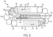
- FIG. 5illustrates a top view of the internal components depicted in FIG. 4 .
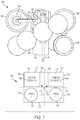
- FIG. 6illustrates a bottom view of the internal components depicted in FIG. 4 .
- FIG. 7illustrates a front view of the internal components depicted in FIG. 4 .
- FIG. 8illustrates a front view of a first alternative arrangement of internal components of the drug delivery device of FIGS. 1-3 .
- FIG. 9illustrates a front view of a second alternative arrangement of internal components of the drug delivery device of FIGS. 1-3 .
- This disclosurepresents various systems, components, and methods for delivering a liquid drug or medicine to a patient or user.
- Each of the systems, components, and methods disclosed hereinprovides one or more advantages over conventional systems, components, and methods.
- Various embodimentsinclude a wearable drug delivery device that can deliver high volumes of one or more liquid drugs stored in one or more corresponding containers to a patient or user.
- the wearable drug delivery devicecan include a first container to store a first liquid drug and a second container to store a second liquid drug.
- a first set of energy transfer spherescan be coupled to a first spring and a first plunger positioned within the first container.
- a second set of energy transfer spherescan be coupled to a second spring and a second plunger positioned within the second container.
- the first springcan expand to advance the first set of energy transfer spheres toward the first plunger to advance the first plunger further into the first cartridge, thereby expelling a portion of the first liquid drug from the first container for delivery to the patient.
- the second springcan expand to advance the second set of energy transfer spheres toward the second plunger to advance the second plunger further into the second cartridge, thereby expelling a portion of the second liquid drug from the second container for delivery to the patient.
- the first and second liquid drugscan be the same drug or can be different drugs.
- the first and second drugscan be delivered in succession or can be mixed for delivery to the patient.
- the wearable drug delivery devicecan be filled or refilled by the patient. Other embodiments are disclosed and described.
- FIG. 1illustrates an exemplary embodiment of a drug delivery device 100 .
- the drug delivery device 100can include a top portion or cover 102 and a lower portion or base 104 .
- the top portion 102 and the lower portion 104can together form a housing of the drug delivery device 100 .
- the top portion 102 and the lower portion 104can be coupled together to form an outside portion of the drug delivery device 100 .
- the top portion 102 and the lower portion 104can be formed from any material including, for example, plastic, metal, rubber, or any combination thereof.
- the drug delivery device 100can be used to deliver one or more therapeutic agents (e.g., one or more drugs) to a patient or user.
- the drug delivery device 100can include two or more containers for retaining or storing liquid drugs.
- the liquid drugscan be the same liquid drug or can be different liquid drugs.
- the drug delivery device 100can be used to deliver the liquid drugs from the containers to the patient. Any type of liquid drug can be stored by the drug delivery device 100 and delivered to the patient.
- the containerscan contain any therapeutic agent such as, for example, a drug, a subcutaneous injectable, a medicine, or a biologic, or any combination thereof.
- the liquid drugs stored by the drug delivery device 100can be delivered in succession or can be combined for delivery to the patient.
- a patient receiving a drug or other medicine (or any liquid) from the drug delivery device 100can also be referred to as a user.
- the drug delivery device 100can provide any amount of the stored liquid drugs to a patient over any period of time. In various embodiments, the drug delivery device 100 can provide the stored liquid drugs to the patient in a single dose over a desired amount of time. In various embodiments, the drug delivery device 100 can provide the stored liquid drugs to the patient over multiple doses. Each of the multiple doses can include substantially the same amount of the liquid drug or drugs or the sizes of the doses can vary. Further, each of the multiple doses can be provided to the patient over substantially the same amount of time or the delivery times can vary. Additionally, the amount of time between multiple doses can be approximately equal or can vary.
- the drug delivery device 100can maintain the liquid drugs within two or more primary drug containers.
- the primary drug containerscan each be a cartridge.
- each cartridgecan be an International Organization for Standardization (ISO) standardized cartridge.
- the drug delivery device 100can be provided to the patient with preloaded and prefilled cartridges.
- the drug delivery device 100can include a slot or opening for a patient to load prefilled cartridges into the drug delivery device 100 .
- the drug delivery device 100can be designed and/or intended for a single use such that after the liquid drugs are delivered to the patient, the drug delivery device 100 can be discarded.
- the primary drug containerscan be filled or refilled by a patient such that the drug delivery device 100 can be reused.
- the drug delivery device 100can include a port for accessing and filling the primary drug containers.
- the drug delivery device 100can include a fill port 106 .
- the fill port 106can provide access to each of the drug containers contained within the drug delivery device 100 such that a user can fill each drug container through the fill port 106 . Since the fill port 106 provides access to each drug container within the drug delivery device 100 , the fill port 106 can be considered a unionized fill port.
- the top portion 102can include a patient interaction element or component 108 .
- the patient interaction element 108can be a push button or other patient input device.
- the patient interaction element 108can be used to activate the drug delivery device 100 .
- the drug delivery device 100can begin delivering the stored liquid drugs to the patient.
- the drug delivery device 100can remain in an idle state of operation.
- the patient interaction element 108can be used to start, stop, and/or restart delivery of the liquid drugs to the patient to enable a patient to dispense multiple doses of one or more liquid drugs.
- the drug delivery device 100can be a wearable drug delivery device 100 .
- the drug delivery device 100can be an on-body delivery system (OBDS) or a portion thereof.
- OBDSon-body delivery system
- the drug delivery device 100can be coupled to a patient in many ways.
- the lower portion 104 of the drug delivery device 100can include an adhesive for attaching to a patient.
- the drug delivery device 100can be attached to a secondary device attached or worn by the patient such that the drug delivery device 100 fits onto or can be coupled to the secondary device.
- FIG. 1illustrates an exemplary form factor of the drug delivery device 100 .
- the drug delivery device 100can be designed according to any desired form factor—for example, according to any desired shape and size of the top and lower portions 102 and 104 . Further, the drug delivery device 100 can include any number of components that can be coupled together to form the housing of the drug delivery device 100 .
- the drug delivery device 100can be a relatively high capacity drug delivery device capable of relativity fast delivery of liquids with relativity high viscosities.
- the drug delivery device 100can include two 5 mL drug cartridges (e.g., two 5 mL ISO drug containers) such that the drug delivery device 100 can store and deliver at least 10 mL of one or more liquid drugs to a user. Accordingly, the drug delivery device 100 can be considered to be a very high volume (VHV) (e.g., 10 mL or more) drug delivery device.
- VHVvery high volume
- the drug delivery device 100can include a first opening or window 110 and a second opening or window 112 .
- the windows 110 and 112can expose a portion of each drug container (e.g., each cartridge) positioned within the drug delivery device 100 .
- the window 110can be positioned adjacent to a first 5 mL drug cartridge and the window 112 can be positioned adjacent to a second 5 mL drug cartridge.
- the windows 110 and 112can allow visual inspection and monitoring of the respective drug containers to, for example, monitor delivery progress or status.
- a patient of the drug delivery device 100can monitor an amount of liquid drug remaining in each drug container. In this way, a patient can monitor dosing status.
- the windows 110 and 112can also enable a patient to inspect the liquid drugs for particles or discoloration.
- the windows 110 and 112can each be covered with a clear material such as plastic to allow a user to view the contents of each respective drug container.
- the windows 110 and 112can be of any size or shape and can be positioned along any portion of the drug delivery device 100 .
- Many conventional drug delivery devices that can store and deliver relatively large volumes of liquid drugs to a userare generally shaped to be long and thin. Such conventional drug delivery devices are generally not comfortable when worn by the patient. Further, many conventional drug delivery devices that can dispense 10 mL or more of a stored liquid drug are not intended to be worn by the patient. In contrast, the drug delivery device 100 can store and deliver 10 mL or more of one or more liquid drugs to the user while being comfortably worn by the patient. Further, in contrast to many conventional drug delivery devices, the drug delivery device 100 can be filled or refilled by a user.
- FIG. 2illustrates a top view of the drug delivery device 100 .
- an exemplary arrangement of the fill port 106 , the patient interaction element 108 , and the viewing windows 110 and 112are shown.
- the drug delivery device 100can have a width 202 of approximately 35 mm.
- the drug delivery device 100can have a length 204 of approximately 91 mm.
- the arrangement of the fill port 106 , the patient interaction element 108 , and the viewing windows 110 and 112allows a patient to conveniently monitor the delivery progress of the stored liquid drugs while also being able to control or activate the drug delivery device 100 when the drug delivery device 100 is worn by the user.
- FIG. 3illustrates a side view of the drug delivery device 100 .
- an exemplary arrangement of the viewing window 112is shown in relation to the top portion 102 and the lower portion 104 of the drug delivery device 100 .
- the drug delivery device 100can have a height 302 of approximately 31 mm.
- the drug delivery device 100can include a user interface.
- the user interfacecan include, for example, a touchscreen, a liquid crystal display (LCD), light emitting diode (LED) display, or any other type of display for presenting information to the patient and/or receiving one or more inputs from the patient.
- the user interfacecan include one or more interfaces for displaying or providing information to the patient and/or receiving information from the patient.
- the user interfacecan provide an electronic display indicating the fill and/or dosing status (or any other operational status) of the drug delivery device 100 .
- the drug delivery device 100can include one or more drive mechanisms.
- a drive mechanismcan be provided for each container that stores, for example, a liquid drug.
- the drive mechanismscan be of the same type of drive mechanism or can be different drive mechanisms.
- Each drive mechanismcan be used to expel a liquid drug from a corresponding container for delivery to the patient.
- each drive mechanismcan be used to expel a desired amount of a liquid drug that is to be provided to the patient over a certain amount of time.
- each drive mechanismcan operate to control a plunger that can expel a portion of a liquid drug from a respective container based on the movement of the plunger.
- the plungercan be positioned within a drug storage container and can be moved within the container by a corresponding drive mechanism.
- drive mechanismscan be used and implemented by the drug delivery device 100 including any of the mechanisms, features, and/or components for storing and delivering a liquid drug from a container to a user as described in U.S. application Ser. No. 15/607,169, filed May 26, 2017, U.S. application Ser. No. 15/607,182, filed May 26, 2017, U.S. Provisional Application No. 62/562,802, filed Sep. 25, 2017, and U.S. Provisional Application No. 62/562,807, filed Sep. 25, 2017, each of which is incorporated by reference in their entirety.
- FIG. 4illustrates a first exemplary arrangement of various internal components 400 of the drug delivery device 100 .
- the various internal components 400 depicted in FIG. 4can be used for storing, for example, one or more liquid drugs, expelling the one or more liquid drugs from respective containers, and for delivering the expelled liquid drugs to a user.
- the drug delivery device 100can include additional components other than those depicted in FIG. 4 .
- the internal components 400can include a first container 402 and a second container 404 .
- the first and second containers 402 and 404can be ISO cartridges.
- the first and second containers 402 and 404can each be 5 mL cartridges and can be of the same size and shape.
- the first container 402can hold or store a first liquid drug 406 .
- the second container 404can hold or store a second liquid drug 408 .
- the first and second liquid drugs 406 and 408can be the same liquid drug or can be different liquid drugs.
- a first plunger 410can be positioned within the first container 402 .
- the first plunger 410can be advanced in a direction 412 to expel the first liquid drug 406 from the first container 402 .
- the first liquid drug 406can be expelled from a first end 414 of the first container 402 based on advancement of the first plunger 410 toward the first end 414 .
- a second plunger 416can be positioned within the second container 404 .
- the second plunger 416can be advanced in a direction 418 to expel the second liquid drug 408 from the second container 404 .
- the second liquid drug 408can be expelled from a first end 420 of the second container 404 based on advancement of the second plunger 416 toward the first end 420 .
- the first end 414 of the first container 402can be coupled to a first fluid path or tubing component 422 .
- the first tubing component 422can be coupled to a needle component 424 .
- the needle component 424can be coupled to the user when it is desired to deliver a stored liquid drug to the user.
- the first plunger 410is advanced in the direction 412 , then a portion of the first liquid drug 406 can be expelled from the first container 402 for delivery to the user by way of the first tubing component 422 and the needle component 424 .
- the first end 420 of the second container 404can be coupled to a second fluid path or tubing component 426 .
- the second tubing component 426can also be coupled to the needle component 424 .
- the needle component 424can be supported by and/or coupled to a structural component 440 .
- the first plunger 410can be moved by operation of a first spring 428 and first energy transfer spheres 430 (or a first set of energy transfer spheres).
- the first spring 428can be a compression spring and can be coupled to the first energy transfer spheres 430 .
- the first energy transfer spheres 430can be coupled to the first plunger 410 .
- the first energy transfer spheres 430can include any number of spheres.
- the first spring 428can be positioned below the second container 404 .
- a track or other guide not shown in FIG. 4can be used to guide the energy transfer spheres 430 to provide coupling between the first spring 428 and the first plunger 410 .
- the first spring 428When the first spring 428 is released and expands, the first spring 428 can provide a force to advance the energy transfer spheres 430 toward the first plunger 410 .
- the force provided by the first spring 428can be transferred to the first plunger 410 by way of the energy transfer spheres 430 , thereby causing the first plunger 410 to advance in the direction 412 .
- the energy transfer spheres 430can be sized to enter an open end of the first container 402 to advance the first plunger 410 further into the first container 402 (e.g., toward the first end 414 ).
- the second plunger 416can be moved by operation of a second spring 432 and second energy transfer spheres 434 (or a second set of energy transfer spheres).
- the second spring 432can be a compression spring and can be coupled to the second energy transfer spheres 434 .
- the second energy transfer spheres 434can be coupled to the second plunger 416 .
- the second energy transfer spheres 434can include any number of spheres.
- the second spring 432can be positioned below the first container 402 .
- a track or other guide not shown in FIG. 4can be used to guide the second energy transfer spheres 434 to provide coupling between the second spring 432 and the second plunger 416 .
- the second spring 432When the second spring 432 is released, the second spring 432 can provide a force to advance the second energy transfer spheres 434 toward the second plunger 416 .
- the force provided by the second spring 432can be transferred to the second plunger 416 by way of the second energy transfer spheres 434 , thereby causing the second plunger 432 to advance in the direction 418 .
- the directions 412 and 418can be approximately opposite.
- the energy transfer spheres 434can be sized to enter an open end of the second container 404 to advance the second plunger 416 further into the second container 404 (e.g., toward the first end 420 ).
- a fill port component 436can be used to access the first and second containers 402 and 404 .
- the fill port component 436can include an opening that can be aligned with the fill port 106 as shown in FIGS. 1 and 2 .
- the fill port component 436can be coupled to the first tubing component 422 and the second tubing component 426 .
- the fill port component 436can enable the user to fill the first container 402 with the first liquid drug 406 through the first tubing component 422 and to fill the second container 404 with the second liquid drug 408 through the second tubing component 426 .
- the fill port component 436can include one or more valves for directing fluid provided by the user to either the first container 402 or the second container 404 such that the first container 402 can be filled with the first liquid drug 406 and the second container 404 can be filled with the second liquid drug 408 .
- the fill port component 436can also be coupled to the needle component 424 .
- a tubing component 438can provide connectivity between the fill port component 436 and the needle component 424 .
- the tubing components 422 and 426can provide connectivity to the fill port component 436 which can then provide the expelled liquid drugs 406 and 408 to the needle component 424 through the tubing component 438 .
- one or more valves of the fill port component 436can direct the flow of the first and second liquid drugs 406 and 408 into the first and second containers 402 and 404 , respectively, or from the first and second containers 402 and 404 to the needle component 424 .
- the first spring 428 and the energy transfer spheres 430can form a portion of a first drive mechanism of the drug delivery device 100 .
- This first drive mechanismas described herein, can be used to deliver the stored first liquid drug 406 to the user.
- the second spring 432 and the energy transfer spheres 434can form a portion of a second drive mechanism of the drug delivery device 100 .
- This second drive mechanismas described herein, can be used to deliver the stored second liquid drug 408 to the user.
- the arrangement of the internal components of the drug delivery device 100 shown in FIG. 4allows the drug delivery device 100 to remain relatively small, compact, and lightweight.
- the drug delivery device 100can have a size and shape (e.g., as shown in FIGS. 1-3 ) that can be comfortable for a user to wear.
- FIG. 5illustrates a top (or overhead) view of the internal components 400 of the drug delivery device 100 shown in FIG. 4 .
- the tubing components 422 , 426 , and 438can each be flexible tubing comprising any suitable material including plastic or stainless steel.
- the tubing component 422 and tubing component 426can have the same inner diameters (e.g., to maintain the same flow rate capabilities from the first and second containers 402 and 404 , respectively) or can have different inner diameters.
- the first container 402is oriented in an approximately opposite direction from an orientation of the second container 404 .
- the first end 420 of the second container 404is located adjacent to and proximate to the fill port component 436 while the first end 414 of the first container 402 is located distal to the fill port component 436 .
- the first end 414 of the first container 402can be positioned closer to a tip or end of the needle component 424 (e.g., a tip or end of the needle component 424 coupled to the user).
- the first end 414 of the first container 402is adjacent to an open end of the second container 404 that enables the energy transfer spheres 434 to enter the second container 404 .
- the first end 420 of the second container 404is adjacent to an open end of the first container 402 that enables the energy transfer spheres 4340 to enter the first container 402 .
- FIG. 6illustrates a bottom (or underside) view of the internal components 400 of the drug delivery device 100 as shown in FIG. 4 .
- FIGS. 5 and 6together illustrate the compact arrangement of the internal components 400 including exemplary positioning of the first spring 428 under the second container 404 and the exemplary positioning of the second spring 432 under the first container 402 .
- the energy transfer spheres 430are shown wrapped around a first end of the arrangement depicted in FIG. 6 and the energy transfer spheres 434 are shown wrapped around a second, opposite end.
- the arrangement of the internal components 400 as shown in FIGS. 4-6enables the overall height of the internal components 400 to be relatively low while maintaining a manageable length of the drug delivery device 100 , thereby providing a comfortable experience by the user when the drug delivery device 100 is worn.
- a first indicator 602represents an applied force from the first spring 428 (or a direction of an applied force from the first spring 428 ).
- the applied force from the first spring 428is transferred by the energy transfer spheres 430 to the first plunger 410 (not shown in FIG. 6 ) of the first container 402 .
- the expansion of the first spring 428 in the direction 602advances the energy transfer spheres 430 toward the first container 402 .
- a second indicator 604represents an applied force from the second spring 432 (or a direction of an applied force from the second spring 432 ).
- the applied force from the second spring 432is transferred by the energy transfer spheres 434 to the second plunger 416 (not shown in FIG. 6 ) of the second container 404 .
- the expansion of the second spring 432advances the energy transfer spheres 434 and, consequently, the second plunger 416 .
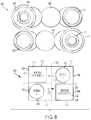
- FIG. 7illustrates a front (or head-on) view of the exemplary arrangement of the various internal components 400 of the drug delivery device 100 as well as a block diagram 700 representing the exemplary arrangement of the various internal components 400 .
- FIG. 7illustrates a view of the exemplary arrangement of the various internal components 400 when facing the needle component 424 and the energy transfer spheres 434 relative to the depictions of the internal components 400 in FIGS. 4-6 .
- the block diagram 700 of FIG. 7functionally represents the internal components 400 in a simplified manner to highlight the exemplary arrangement of the internal components 400 depicted in FIGS. 4-6 .
- the block diagram 700represents the drug delivery device 100 when it incorporates the internal components 400 as arranged in FIGS. 4-6 .
- a bottom surface 702 , a top surface 704 , a first side surface 706 , and a second side surface 708represent the housing and/or outer surfaces of the drug delivery device 100 .
- the first and second springs 428 and 432are positioned adjacent to the bottom surface 702 .
- the first and second containers 402 and 404are positioned adjacent to the top surface 704 .
- the first spring 428is positioned under the second container 404 and the second spring 432 is positioned under the first container 402 .
- Indicator 710represents the application of a force (or direction or path of a force) from the first spring 428 (e.g., via energy transfer spheres 430 ) to expel a liquid drug (e.g., the liquid drug 406 ) from the first container 402 .
- Indicator 712represents the application of a force (or direction or path of a force) from the second spring 432 (e.g., via energy transfer spheres 434 ) to expel a liquid drug (e.g., the liquid drug 408 ) from the second container 404 .
- the drive mechanism associated with the first container 402which can include the first spring 428 and the energy transfer spheres 430 —crosses the drive mechanism associated with the second container 402 —which can include the second spring 432 and the energy transfer spheres 434 .
- This arrangementprovides a suitable path for the energy transfer spheres 430 and 434 that is not too tight or narrow while still providing a compact arrangement of the internal components 400 .
- FIG. 7further illustrates exemplary positioning of windows or openings 714 and 716 for viewing the first and second containers 402 and 404 , respectively.
- the window 714can be used to view a portion of the first container 402 .
- the window 714can be arranged to occupy a portion 718 of the top surface 704 and/or a portion 720 of the side surface 706 .
- the window 716can be arranged to occupy a portion 722 of the top surface 704 and/or a portion 724 of the side surface 708 .
- the block diagram 700includes a first central axis (or plane) 726 and a second central axis (or plane) 728 .
- the first axis 726divides the block diagram 700 between a right side and a left side.
- the right sidecan include the first spring 428 and the second container 404 .
- the left sidecan include the second spring 432 and the first container 402 .
- the second axis 728divides the block diagram 700 between a top portion and a bottom portion.
- the top portioncan include the first and second containers 402 and 404 .
- the bottom portioncan include the first and second springs 428 and 432 .
- indicator 710traverses or crosses the first and second axes 726 and 728 —accordingly, the first spring 428 operates on the first container 402 by applying a force through the energy transfer spheres 430 that traverses both the first and second axes 726 and 728 .
- indicator 712traverses or crosses the first and second axes 726 and 728 —accordingly, the second spring 432 operates on the second container 404 by applying a force through the energy transfer spheres 434 that traverses both the first and second axes 726 and 728 .
- the first container 402can be oriented in an opposite direction relative to an orientation of the second container 404 .
- the first end 420 of the second container 404can be positioned closer to the fill port component 436 while the first end 414 of the first container 402 can be positioned further from the fill port component 436 .
- the first plunger 410can be moved in the direction 412 to expel the first liquid drug 406 that is approximately opposite to the direction 418 that the plunger 416 is moved to expel the second liquid drug 408 .
- the direction 602 of expansion of the first spring 428can be approximately opposite to the direction 604 of expansion of the second spring 432 .
- the direction 602can be approximately opposite to the direction 412 of the first plunger 410 while the direction 604 can be approximately opposite to the direction 418 of the second plunger 416 .
- the drug delivery device 100can be operated to expel and deliver the first liquid drug 406 to the user before subsequently expelling and delivering the second liquid drug 408 to the user.
- the first liquid drug 406 and the second liquid drug 408can be mixed and delivered to the user in any combination. Any ratio of mixing the first and second liquid drugs 406 and 408 can be provided. The ratio of mixing can be based on the amount of the first and second liquid drugs 406 and 408 stored in the first and second containers 402 and 404 , respectively (e.g., a fill ratio between the first and second containers 402 and 404 ).
- the ratio of mixingcan be based on rates of expelling the first and second liquid drugs 406 and 408 from the first and second containers 402 and 404 , respectively.
- the drug delivery device 100can be used to reconstitute one or more drugs for delivery to the user.
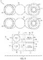
- FIG. 8illustrates a front view of a first alternative arrangement of various internal components 800 of the drug delivery device 100 as well as a block diagram 802 representing the exemplary arrangement of the various internal components 800 .
- the block diagram 802 of FIG. 8functionally represents the internal components 800 in a simplified manner to highlight the exemplary arrangement of the internal components 800 .
- Various additional componentsare not shown for simplicity (e.g., the needle component 424 ) to better illustrate the exemplary arrangement of storage containers and drive mechanisms.
- the block diagram 802represents the drug delivery device 100 when it incorporates the internal components 800 .
- the first spring 428 and the first container 402are positioned adjacent to the top surface 704 .
- the second spring 432 and the second container 404are positioned adjacent to the bottom surface 702 .
- the second spring 432is positioned under the first container 402 and the second container 404 is positioned under the first spring 428 .
- the first and second containers 402 and 404can be oriented in the same direction (e.g., the first and second plungers 410 and 416 can be moved in the same direction to expel the first and second liquid drugs 406 and 408 , respectively).
- the first and second springs 428 and 432can also be oriented in the same direction (e.g., the first and second springs 428 and 432 can extend in the same direction to advance forward the first and second sets of energy transfer spheres 430 and 434 , respectively).
- the application of a force from the first spring 428 (e.g., via the energy transfer spheres 430 ) to expel a liquid drug (e.g., the liquid drug 406 ) from the first container 402is represented by indicator 710 , which is positioned above central axis 728 , and traverses or crosses central axis 726 .
- the application of a force from the second spring 432 (e.g., via the energy transfer spheres 434 ) to expel a liquid drug (e.g., the liquid drug 408 ) from the second container 404is represented by indicator 712 , which is positioned below central axis 728 , and traverses or crosses central axis 726 .
- indicators 710 and 712represent applied forces (or directions or paths of applied forces) that are applied in approximately opposite directions. This arrangement provides a suitable path for the energy transfer spheres 430 and 434 that is not too tight or narrow while still providing a compact arrangement of the internal components 800 .
- FIG. 8further illustrates exemplary positioning of windows or openings 714 and 804 for viewing the first and second containers 402 and 404 , respectively.
- the window 714can be used to view a portion of the first container 402 .
- the window 714can be arranged to occupy a portion 718 of the top surface 704 and/or a portion 720 of the side surface 706 .
- the window 804can be arranged to occupy a portion 806 of the bottom surface 702 and/or a portion 808 of the side surface 708 .
- the right side of the block diagram 902can include the first spring 428 and the second container 404 .
- the left side of the block diagram 902can include the second spring 432 and the first container 402 .
- FIG. 9illustrates a front view of a second alternative arrangement of various internal components 900 of the drug delivery device 100 as well as a block diagram 902 representing the exemplary arrangement of the various internal components 900 .
- the block diagram 902 of FIG. 9functionally represents the internal components 900 in a simplified manner to highlight the exemplary arrangement of the internal components 900 . Further, various components are not shown for simplicity (e.g., the needle component 424 ) to better illustrate the exemplary arrangement of storage containers and drive mechanisms.
- the block diagram 902represents the drug delivery device 100 when it incorporates the internal components 900 .
- the first spring 428 and the first container 402are positioned adjacent to the top surface 704 .
- the second spring 432 and the second container 404are positioned adjacent to the bottom surface 702 .
- the second spring 432is positioned under the first spring 428 and the second container 404 is positioned under the first container 402 .
- the first and second containers 402 and 404can be oriented in the same direction.
- the first and second springs 428 and 432can also be oriented in the same direction.
- the application of a force from the first spring 428 (e.g., via the energy transfer spheres 430 ) to expel a liquid drug (e.g., the liquid drug 406 ) from the first container 402is represented by indicator 710 , which is positioned above central axis 728 and traverses or crosses central axis 726 .
- the application of a force from the second spring 432 (e.g., via the energy transfer spheres 434 ) to expel a liquid drug (e.g., the liquid drug 408 ) from the second container 404is represented by indicator 712 , which is positioned below central axis 728 and traverses or crosses central axis 726 .
- indicators 710 and 712represent applied forces (or directions or paths of applied forces) that are applied in the same direction.
- This arrangementprovides a suitable path for the energy transfer spheres 430 and 434 that is not too tight or narrow while still providing a compact arrangement of the internal components 900 .
- FIG. 9further illustrates exemplary positioning of windows or openings 904 and 910 for viewing the first and second containers 402 and 404 , respectively.
- the window 904can be used to view a portion of the first container 402 .
- the window 904can be arranged to occupy a portion 906 of the top surface 704 and/or a portion 908 of the side surface 708 .
- the window 910can be arranged to occupy a portion 912 of the bottom surface 702 and/or a portion 914 of the side surface 708 .
- the right side of the block diagram 902can include the first container 402 and the second container 404 .
- the left side of the block diagram 902can include the first spring 428 and the second spring 432 .
- Various embodiments described hereinincluding, for example the various exemplary arrangements of internal components 400 , 800 , and 900 depicted in FIGS. 7-9 —enable relatively large volumes of one or more drugs (e.g., 10 mL or more) to be delivered to the user.
- Various embodiments described hereincan store the one or more drugs across two or more containers. By using more than one container, a stroke of any spring (or other delivery mechanism) used to expel the liquid drugs from their respective containers can be shorter than the stroke of any spring (or other delivery mechanism) used in conventional drug delivery devices that are used for high volume drug delivery. As a result, an efficiency of the drive mechanism used for delivery of the liquid drugs within the embodiments described herein can be improved over conventional devices.
- the arrangement of the internal components 400 , 800 , and 900enables the drug delivery device 100 to made in a compact form to improve the comfort of a user that wears the drug delivery device 100 .
- the arrangement of components as shown in at least FIGS. 7-9enable the internal components for storing and delivering large volumes of one or more drugs to be arranged in a highly efficient manner that is compact, allowing the wearable drug delivery device to remain small and comfortable to wear.
Landscapes
- Health & Medical Sciences (AREA)
- Heart & Thoracic Surgery (AREA)
- Vascular Medicine (AREA)
- Engineering & Computer Science (AREA)
- Anesthesiology (AREA)
- Biomedical Technology (AREA)
- Hematology (AREA)
- Life Sciences & Earth Sciences (AREA)
- Animal Behavior & Ethology (AREA)
- General Health & Medical Sciences (AREA)
- Public Health (AREA)
- Veterinary Medicine (AREA)
- Dermatology (AREA)
- Infusion, Injection, And Reservoir Apparatuses (AREA)
Abstract
Description
Claims (20)
Priority Applications (2)
| Application Number | Priority Date | Filing Date | Title |
|---|---|---|---|
| US15/912,923US10695485B2 (en) | 2017-03-07 | 2018-03-06 | Very high volume user filled drug delivery device |
| US16/884,832US11229740B2 (en) | 2017-03-07 | 2020-05-27 | Very high volume user filled drug delivery device |
Applications Claiming Priority (2)
| Application Number | Priority Date | Filing Date | Title |
|---|---|---|---|
| US201762468152P | 2017-03-07 | 2017-03-07 | |
| US15/912,923US10695485B2 (en) | 2017-03-07 | 2018-03-06 | Very high volume user filled drug delivery device |
Related Child Applications (1)
| Application Number | Title | Priority Date | Filing Date |
|---|---|---|---|
| US16/884,832ContinuationUS11229740B2 (en) | 2017-03-07 | 2020-05-27 | Very high volume user filled drug delivery device |
Publications (2)
| Publication Number | Publication Date |
|---|---|
| US20180256815A1 US20180256815A1 (en) | 2018-09-13 |
| US10695485B2true US10695485B2 (en) | 2020-06-30 |
Family
ID=63446006
Family Applications (2)
| Application Number | Title | Priority Date | Filing Date |
|---|---|---|---|
| US15/912,923Active2038-04-05US10695485B2 (en) | 2017-03-07 | 2018-03-06 | Very high volume user filled drug delivery device |
| US16/884,832ActiveUS11229740B2 (en) | 2017-03-07 | 2020-05-27 | Very high volume user filled drug delivery device |
Family Applications After (1)
| Application Number | Title | Priority Date | Filing Date |
|---|---|---|---|
| US16/884,832ActiveUS11229740B2 (en) | 2017-03-07 | 2020-05-27 | Very high volume user filled drug delivery device |
Country Status (1)
| Country | Link |
|---|---|
| US (2) | US10695485B2 (en) |
Cited By (22)
| Publication number | Priority date | Publication date | Assignee | Title |
|---|---|---|---|---|
| US11229736B2 (en) | 2018-06-06 | 2022-01-25 | Insulet Corporation | Linear shuttle pump for drug delivery |
| US11229741B2 (en) | 2012-03-30 | 2022-01-25 | Insulet Corporation | Fluid delivery device, transcutaneous access tool and fluid drive mechanism for use therewith |
| US11229740B2 (en)* | 2017-03-07 | 2022-01-25 | Insulet Corporation | Very high volume user filled drug delivery device |
| US11280327B2 (en) | 2017-08-03 | 2022-03-22 | Insulet Corporation | Micro piston pump |
| US11369735B2 (en) | 2019-11-05 | 2022-06-28 | Insulet Corporation | Component positioning of a linear shuttle pump |
| US11406565B2 (en) | 2015-03-10 | 2022-08-09 | Regeneran Pharmaceuticals, Inc. | Aseptic piercing system and method |
| US11439765B2 (en) | 2016-08-14 | 2022-09-13 | Insulet Corporation | Variable fill drug delivery device |
| US11446435B2 (en) | 2018-11-28 | 2022-09-20 | Insulet Corporation | Drug delivery shuttle pump system and valve assembly |
| US11517674B2 (en) | 2015-06-30 | 2022-12-06 | Kaleo, Inc. | Auto-injectors for administration of a medicament within a prefilled syringe |
| US11547801B2 (en) | 2017-05-05 | 2023-01-10 | Regeneron Pharmaceuticals, Inc. | Auto-injector |
| US11633541B2 (en) | 2017-01-19 | 2023-04-25 | Insulet Corporation | Cartridge hold-up volume reduction |
| US11672917B2 (en) | 2018-05-31 | 2023-06-13 | Insulet Corporation | Drug cartridge with drive system |
| USD994110S1 (en) | 2011-01-26 | 2023-08-01 | Kaleo, Inc. | Medicament delivery device cover |
| USD994111S1 (en) | 2008-05-12 | 2023-08-01 | Kaleo, Inc. | Medicament delivery device cover |
| US11786668B2 (en) | 2017-09-25 | 2023-10-17 | Insulet Corporation | Drug delivery devices, systems, and methods with force transfer elements |
| USD1007676S1 (en) | 2021-11-16 | 2023-12-12 | Regeneron Pharmaceuticals, Inc. | Wearable autoinjector |
| US12017047B2 (en) | 2019-08-09 | 2024-06-25 | Kaleo, Inc. | Devices and methods for delivery of substances within a prefilled syringe |
| US12268847B1 (en) | 2021-02-10 | 2025-04-08 | Kaleo, Inc. | Devices and methods for delivery of substances within a medicament container |
| US12318594B2 (en) | 2016-05-26 | 2025-06-03 | Insulet Corporation | On-body interlock for drug delivery device |
| US12359903B2 (en) | 2021-05-28 | 2025-07-15 | Insulet Corporation | Spring-based status sensors |
| US12377208B2 (en) | 2021-01-08 | 2025-08-05 | Insulet Corporation | Single actuated precision dose intermediate pumping chamber |
| US12440617B2 (en) | 2022-01-05 | 2025-10-14 | Insulet Corporation | Linear activated drug dosing pump system |
Families Citing this family (13)
| Publication number | Priority date | Publication date | Assignee | Title |
|---|---|---|---|---|
| EP1762259B2 (en) | 2005-09-12 | 2025-01-01 | Unomedical A/S | Inserter for an infusion set with a first and second spring units |
| WO2012123274A1 (en) | 2011-03-14 | 2012-09-20 | Unomedical A/S | Inserter system with transport protection |
| USD794771S1 (en)* | 2015-07-10 | 2017-08-15 | Unitract Syringe Pty Ltd. | Drug delivery pump |
| US20170348479A1 (en) | 2016-06-03 | 2017-12-07 | Bryan Choate | Adhesive system for drug delivery device |
| USD872733S1 (en) | 2017-03-14 | 2020-01-14 | Insulet Corporation | Display screen with a graphical user interface |
| USD872734S1 (en) | 2017-03-14 | 2020-01-14 | Insulet Corporation | Display screen with a graphical user interface |
| USD836770S1 (en)* | 2017-09-25 | 2018-12-25 | Insulet Corporation | Drug delivery device |
| AU2019308251B2 (en) | 2018-07-17 | 2023-05-18 | Insulet Corporation | Low force valves for drug delivery pumps |
| USD882760S1 (en)* | 2018-07-22 | 2020-04-28 | Sorrel Medical Ltd. | Medical drug delivery device |
| US11458292B2 (en) | 2019-05-20 | 2022-10-04 | Unomedical A/S | Rotatable infusion device and methods thereof |
| US11305333B2 (en) | 2020-03-31 | 2022-04-19 | Insulet Corporation | Methods for forming low stress component for medical devices |
| WO2022046995A1 (en) | 2020-08-27 | 2022-03-03 | Insulet Corporation | Wearable micro-dosing drug delivery device |
| EP4101482A1 (en) | 2021-06-07 | 2022-12-14 | Insulet Corporation | Exercise safety prediction based on physiological conditions |
Citations (159)
| Publication number | Priority date | Publication date | Assignee | Title |
|---|---|---|---|---|
| US1441508A (en) | 1921-12-06 | 1923-01-09 | Jensen Anton Marius | Cylindrical slide valve |
| GB357139A (en) | 1929-06-14 | 1931-09-14 | Paul Von Vago | |
| US2198666A (en) | 1936-09-30 | 1940-04-30 | Lakeland Foundation | Syringe |
| GB810488A (en) | 1955-03-01 | 1959-03-18 | Eduard Woydt | Liquid pressure piston-engine or reciprocating pump |
| CA606281A (en) | 1960-10-04 | Dann Morris | Cartridge for metering syringe | |
| FR2096275A5 (en) | 1970-06-13 | 1972-02-11 | Ismatec Sa | |
| US3885662A (en) | 1973-12-26 | 1975-05-27 | Ibm | Steerable follower selection mechanism |
| US3946732A (en) | 1973-08-08 | 1976-03-30 | Ampoules, Inc. | Two-chamber mixing syringe |
| IL46017A (en) | 1974-11-07 | 1977-11-30 | Ampoules Inc | Two-chamber mixing syringe |
| US4108177A (en) | 1976-04-23 | 1978-08-22 | Michel Louis Paul Pistor | Automatic injector device |
| FR2455269A1 (en) | 1978-01-17 | 1980-11-21 | Marceau Serge | Dynamic dosing of liquid food product - utilises compressed air operation of cylinders to move liquid dose to outlet |
| US4268150A (en) | 1980-01-28 | 1981-05-19 | Laurence Chen | Disposable camera with simplified film advance and indicator |
| WO1981001658A1 (en) | 1979-12-13 | 1981-06-25 | M Loeb | Wearable insulin infusion system having a tubular reservoir and a positive displacement metering means |
| US4313439A (en)* | 1980-03-24 | 1982-02-02 | Biotek, Inc. | Automated, spring-powered medicament infusion system |
| US4424720A (en) | 1980-12-15 | 1984-01-10 | Ivac Corporation | Mechanism for screw drive and syringe plunger engagement/disengagement |
| US4435173A (en) | 1982-03-05 | 1984-03-06 | Delta Medical Industries | Variable rate syringe pump for insulin delivery |
| US4498843A (en) | 1982-08-02 | 1985-02-12 | Schneider Philip H | Insulin infusion pump |
| US4507115A (en) | 1981-04-01 | 1985-03-26 | Olympus Optical Co., Ltd. | Medical capsule device |
| US4551134A (en) | 1982-08-06 | 1985-11-05 | Nuvatec, Inc. | Intravenous set |
| US4562751A (en) | 1984-01-06 | 1986-01-07 | Nason Clyde K | Solenoid drive apparatus for an external infusion pump |
| US4585439A (en) | 1983-09-07 | 1986-04-29 | Disetronic Ag. | Portable infusion unit |
| US4601707A (en) | 1980-06-03 | 1986-07-22 | Albisser Anthony M | Insulin infusion device |
| WO1986006796A1 (en) | 1985-05-15 | 1986-11-20 | Henning Munk Ejlersen | A hose pump, in particular an insulin pump |
| US4634427A (en) | 1984-09-04 | 1987-01-06 | American Hospital Supply Company | Implantable demand medication delivery assembly |
| US4671429A (en) | 1983-11-15 | 1987-06-09 | Thomas J. Lipton, Inc. | Method and apparatus for volumetric dosing viscous products |
| US4678408A (en) | 1984-01-06 | 1987-07-07 | Pacesetter Infusion, Ltd. | Solenoid drive apparatus for an external infusion pump |
| US4684368A (en) | 1984-06-01 | 1987-08-04 | Parker Hannifin Corporation | Inverted pump |
| US4755169A (en) | 1985-05-20 | 1988-07-05 | Survival Technology, Inc. | Automatic medicament ingredient mixing and injecting apparatus |
| US4846797A (en)* | 1985-05-14 | 1989-07-11 | Intelligent Medicine, Inc. | Syringe positioning device for enhancing fluid flow control |
| US4898579A (en) | 1987-06-26 | 1990-02-06 | Pump Controller Corporation | Infusion pump |
| US4944659A (en) | 1987-01-27 | 1990-07-31 | Kabivitrum Ab | Implantable piezoelectric pump system |
| US4969874A (en) | 1987-05-18 | 1990-11-13 | Disetronic Ag | Infusion device |
| US5007458A (en) | 1990-04-23 | 1991-04-16 | Parker Hannifin Corporation | Poppet diaphragm valve |
| US5062841A (en) | 1988-08-12 | 1991-11-05 | The Regents Of The University Of California | Implantable, self-regulating mechanochemical insulin pump |
| US5205819A (en) | 1989-05-11 | 1993-04-27 | Bespak Plc | Pump apparatus for biomedical use |
| US5213483A (en) | 1991-06-19 | 1993-05-25 | Strato Medical Corporation | Peristaltic infusion pump with removable cassette and mechanically keyed tube set |
| DE4200595A1 (en) | 1992-01-13 | 1993-07-15 | Michail Efune | Assembly group for infusion set for insulin pump - involves steel needle inside plastics cannula with only limited axial movement and drawn back into cannula during infusion. |
| US5261882A (en) | 1993-04-26 | 1993-11-16 | Sealfon Andrew I | Negator spring-powered syringe |
| US5277338A (en) | 1990-12-21 | 1994-01-11 | Odin Developments Limited | Fluid metering apparatus |
| US5281202A (en) | 1991-09-03 | 1994-01-25 | Fresenius Ag | Device for draining a flexible fluid container |
| US5346476A (en) | 1992-04-29 | 1994-09-13 | Edward E. Elson | Fluid delivery system |
| US5364342A (en) | 1992-02-05 | 1994-11-15 | Nestle S.A. | Microsurgical cassette |
| US5433710A (en) | 1993-03-16 | 1995-07-18 | Minimed, Inc. | Medication infusion pump with fluoropolymer valve seat |
| JPH08238324A (en) | 1995-03-04 | 1996-09-17 | Nissho Corp | Means for mixed injection of plural medicinal liquids |
| US5582593A (en) | 1994-07-21 | 1996-12-10 | Hultman; Barry W. | Ambulatory medication delivery system |
| US5637095A (en) | 1995-01-13 | 1997-06-10 | Minimed Inc. | Medication infusion pump with flexible drive plunger |
| US5665070A (en) | 1995-01-19 | 1997-09-09 | I-Flow Corporation | Infusion pump with magnetic bag compression |
| US5713875A (en) | 1994-07-29 | 1998-02-03 | Abbott Laboratories | System for administration of a liquid agent to a patient with a syringe pump |
| US5747350A (en) | 1993-04-02 | 1998-05-05 | Boehringer Mannheim Gmbh | System for dosing liquids |
| US5748827A (en) | 1996-10-23 | 1998-05-05 | University Of Washington | Two-stage kinematic mount |
| US5776103A (en) | 1995-10-11 | 1998-07-07 | Science Incorporated | Fluid delivery device with bolus injection site |
| US5779676A (en) | 1995-10-11 | 1998-07-14 | Science Incorporated | Fluid delivery device with bolus injection site |
| US5785688A (en) | 1996-05-07 | 1998-07-28 | Ceramatec, Inc. | Fluid delivery apparatus and method |
| US5797881A (en) | 1996-06-20 | 1998-08-25 | Gadot; Amir | Intravenous infusion apparatus |
| US5800397A (en) | 1995-04-20 | 1998-09-01 | Invasatec, Inc. | Angiographic system with automatic high/low pressure switching |
| US5807075A (en) | 1993-11-23 | 1998-09-15 | Sarcos, Inc. | Disposable ambulatory microprocessor controlled volumetric pump |
| EP0867196A2 (en) | 1997-03-26 | 1998-09-30 | Disetronic Licensing AG | Catheter system for transdermal passages |
| US5839467A (en) | 1993-10-04 | 1998-11-24 | Research International, Inc. | Micromachined fluid handling devices |
| WO1998055073A1 (en) | 1997-06-03 | 1998-12-10 | Kunshan Wang | A medical apparatus comprising an elastic valve-type stopper and a piercing needle |
| WO1999010040A1 (en) | 1997-08-27 | 1999-03-04 | Science Incorporated | Fluid delivery device with temperature controlled energy source |
| WO1999010049A1 (en) | 1997-08-29 | 1999-03-04 | Cycle-Ops Products, Inc. | Exercise resistance device |
| US5891097A (en) | 1994-08-12 | 1999-04-06 | Japan Storage Battery Co., Ltd. | Electrochemical fluid delivery device |
| US5897530A (en) | 1997-12-24 | 1999-04-27 | Baxter International Inc. | Enclosed ambulatory pump |
| US5906597A (en) | 1998-06-09 | 1999-05-25 | I-Flow Corporation | Patient-controlled drug administration device |
| US5911716A (en) | 1992-01-24 | 1999-06-15 | I-Flow Corporation | Platen pump |
| US5919167A (en) | 1998-04-08 | 1999-07-06 | Ferring Pharmaceuticals | Disposable micropump |
| US5957890A (en) | 1997-06-09 | 1999-09-28 | Minimed Inc. | Constant flow medication infusion pump |
| WO1999062576A1 (en) | 1998-06-04 | 1999-12-09 | Elan Corporation, Plc | Gas driven drug delivery device |
| US6019747A (en) | 1997-10-21 | 2000-02-01 | I-Flow Corporation | Spring-actuated infusion syringe |
| US6190359B1 (en) | 1996-04-30 | 2001-02-20 | Medtronic, Inc. | Method and apparatus for drug infusion |
| US6200293B1 (en) | 1997-08-27 | 2001-03-13 | Science Incorporated | Fluid delivery device with temperature controlled energy source |
| WO2001078812A1 (en) | 2000-04-13 | 2001-10-25 | Novo Nordisk A/S | A drug delivery device provided with a one-way mechanism |
| US20010056258A1 (en) | 2000-03-22 | 2001-12-27 | Evans Robert F. | Drug delivery and monitoring system |
| EP1177802A1 (en) | 2000-07-31 | 2002-02-06 | Becton Dickinson and Company | Wearable, self-contained drug infusion device |
| US20020029018A1 (en) | 1996-03-30 | 2002-03-07 | Peter Jeffrey | Materials delivery device |
| US6363609B1 (en) | 2000-10-20 | 2002-04-02 | Short Block Technologies, Inc. | Method and apparatus for aligning crankshaft sections |
| WO2002026282A2 (en) | 2000-06-28 | 2002-04-04 | Science Incorporated | Fluid delivery device with light activated energy source |
| US6375638B2 (en) | 1999-02-12 | 2002-04-23 | Medtronic Minimed, Inc. | Incremental motion pump mechanisms powered by shape memory alloy wire or the like |
| WO2002076535A1 (en) | 2001-03-27 | 2002-10-03 | Dca Design International Limited | Improvements in and relating to an injection device |
| US6474219B2 (en) | 2000-03-24 | 2002-11-05 | Novo Nordisk A/S | Flexible piston rod |
| US20020173769A1 (en) | 2001-05-18 | 2002-11-21 | Gray Larry B. | Infusion set for a fluid pump |
| US6485461B1 (en) | 2000-04-04 | 2002-11-26 | Insulet, Inc. | Disposable infusion device |
| US6485462B1 (en) | 1997-08-27 | 2002-11-26 | Science Incorporated | Fluid delivery device with heat activated energy source |
| US6488652B1 (en) | 1998-02-02 | 2002-12-03 | Medtronic, Inc. | Safety valve assembly for implantable benefical agent infusion device |
| US6520936B1 (en) | 1999-06-08 | 2003-02-18 | Medtronic Minimed, Inc. | Method and apparatus for infusing liquids using a chemical reaction in an implanted infusion device |
| US20030040715A1 (en) | 2001-08-21 | 2003-02-27 | D'antonio Nicholas F. | Hypodermic jet injection kit |
| US6537249B2 (en) | 2000-12-18 | 2003-03-25 | Science, Incorporated | Multiple canopy |
| NL1019126C1 (en) | 2001-10-05 | 2003-04-08 | Fondse Valves B V | Dosing pump for e.g. measuring intercellular moisture, contains pump chamber with ejector and sliding part for sealing inlet and outlet ports |
| US6569115B1 (en) | 1997-08-28 | 2003-05-27 | Mdc Investment Holdings, Inc. | Pre-filled retractable needle injection device |
| US20030109827A1 (en) | 2001-12-07 | 2003-06-12 | Elan Pharma International Limited | Drug delivery system and method |
| US6595956B1 (en) | 1998-03-23 | 2003-07-22 | Joseph Gross | Drug delivery device |
| WO2003097133A1 (en) | 2002-05-17 | 2003-11-27 | Owen Mumford Limited | Injection device with automatically retractable needle |
| US6656158B2 (en) | 2002-04-23 | 2003-12-02 | Insulet Corporation | Dispenser for patient infusion device |
| US6699218B2 (en) | 2000-11-09 | 2004-03-02 | Insulet Corporation | Transcutaneous delivery means |
| US20040064088A1 (en) | 2002-09-30 | 2004-04-01 | William Gorman | Dispenser components and methods for patient infusion device |
| US20040068224A1 (en) | 2002-10-02 | 2004-04-08 | Couvillon Lucien Alfred | Electroactive polymer actuated medication infusion pumps |
| US20040069044A1 (en) | 1999-04-29 | 2004-04-15 | Gilad Lavi | Device for measuring a volume of drug |
| US6723072B2 (en) | 2002-06-06 | 2004-04-20 | Insulet Corporation | Plunger assembly for patient infusion device |
| WO2004056412A2 (en) | 2002-12-23 | 2004-07-08 | M2 Medical A/S | A disposable, wearable insulin dispensing device, a combination of such a device and a programming controller and a method of controlling the operation of such a device |
| US20040153032A1 (en) | 2002-04-23 | 2004-08-05 | Garribotto John T. | Dispenser for patient infusion device |
| US20050020980A1 (en) | 2003-06-09 | 2005-01-27 | Yoshio Inoue | Coupling system for an infusion pump |
| US6851260B2 (en) | 2001-01-17 | 2005-02-08 | M 2 Medical A/S | Shape memory alloy actuator |
| US6883778B1 (en) | 1996-11-18 | 2005-04-26 | Nypro Inc. | Apparatus for reducing fluid drawback through a medical valve |
| US20050203461A1 (en) | 2002-04-23 | 2005-09-15 | Insulet Corporation | Transcutaneous fluid delivery system |
| US20050238507A1 (en) | 2002-04-23 | 2005-10-27 | Insulet Corporation | Fluid delivery device |
| US20060041229A1 (en) | 2002-07-16 | 2006-02-23 | Insulet Corporation | Flow restriction system and method for patient infusion device |
| US20060079765A1 (en) | 2004-10-13 | 2006-04-13 | Liebel-Flarsheim Company | Powerhead of a power injection system |
| US20060173439A1 (en) | 2005-01-18 | 2006-08-03 | Thorne Gale H Jr | Syringe drive system |
| US20060178633A1 (en) | 2005-02-03 | 2006-08-10 | Insulet Corporation | Chassis for fluid delivery device |
| US7160272B1 (en) | 2002-05-31 | 2007-01-09 | Elcam Plastic | Y-site medical valve |
| WO2007066152A2 (en) | 2005-12-08 | 2007-06-14 | Owen Mumford Ltd | Substance delivery device |
| US20080114304A1 (en) | 2006-11-13 | 2008-05-15 | Medical Components, Inc | Syringe for sequential expression of different liquids and method of using same |
| US20080172028A1 (en) | 2006-10-17 | 2008-07-17 | Blomquist Michael L | Insulin pump having selectable insulin absorption models |
| US20090024083A1 (en)* | 2007-06-25 | 2009-01-22 | Kriesel Marshall S | Fluid dispenser with additive sub-system |
| WO2009039203A2 (en) | 2007-09-17 | 2009-03-26 | Satish Sundar | High precision infusion pump controller |
| US20100036326A1 (en) | 2007-04-19 | 2010-02-11 | Rudolf Matusch | Disposable injector comprising at least one draw hook and a sliding wedge-type gear for unlocking a locking element |
| US7771392B2 (en) | 2007-11-29 | 2010-08-10 | Roche Diagnostics Operations, Inc. | Lead screw delivery device using reusable shape memory actuator drive |
| US20100241066A1 (en) | 2006-05-29 | 2010-09-23 | Novo Nordisk A/S | Mechanism for Injection Device |
| WO2010139793A1 (en) | 2009-06-04 | 2010-12-09 | Novo Nordisk A/S | Mixing device with piston coupling arrangement |
| US7914499B2 (en)* | 2006-03-30 | 2011-03-29 | Valeritas, Inc. | Multi-cartridge fluid delivery device |
| US20110144586A1 (en) | 2009-07-30 | 2011-06-16 | Tandem Diabetes Care, Inc. | Infusion pump system with disposable cartridge having pressure venting and pressure feedback |
| WO2011075042A1 (en) | 2009-12-14 | 2011-06-23 | Shl Group Ab | Medicament delivery device |
| WO2011133823A1 (en) | 2010-04-21 | 2011-10-27 | Abbott Biotechnology Ltd. | Wearable automatic injection device for controlled delivery of therapeutic agents |
| WO2012073032A1 (en) | 2010-12-02 | 2012-06-07 | Oval Medical Technologies Limited | A drive assembly for an autoinjector and a method of assembling an autoinjector |
| EP2468338A1 (en) | 2010-12-21 | 2012-06-27 | Sanofi-Aventis Deutschland GmbH | Auto-injector |
| US20130006213A1 (en) | 2009-11-03 | 2013-01-03 | Theo Arnitz | Device for substantially germ-free provision of a fluid medium |
| US20130017099A1 (en) | 2010-03-17 | 2013-01-17 | Sensile Pat Ag | Micropump |
| US8382703B1 (en)* | 2011-10-18 | 2013-02-26 | King Saud University | Piezoelectric dual-syringe insulin pump |
| US20130064701A1 (en) | 2011-09-12 | 2013-03-14 | Satoshi Konishi | Pumping apparatus |
| WO2013050535A2 (en) | 2011-10-07 | 2013-04-11 | Novo Nordisk A/S | System for determining position of element |
| US8499913B2 (en) | 2011-05-20 | 2013-08-06 | The Boeing Company | Shape memory alloy actuator system and method |
| WO2013137893A1 (en) | 2012-03-15 | 2013-09-19 | Becton, Dickinson And Company | Multiple use disposable injection pen |
| US20130245545A1 (en) | 2011-09-20 | 2013-09-19 | Medingo Ltd. | Drug Injection Devices, Systems and Methods |
| US20130267932A1 (en) | 2010-11-03 | 2013-10-10 | Sanofi-Aventis Deutschland Gmbh | Needle Assembly for the Delivery of at Least Two Medicaments |
| US20140018730A1 (en) | 2011-03-31 | 2014-01-16 | Sanofi-Aventis Deutschland Gmbh | Dosing Mechanism |
| EP2703024A1 (en) | 2011-04-26 | 2014-03-05 | Taisei Kako Co., Ltd. | Elastic sealing body for prefilled syringe |
| US20140142508A1 (en) | 2012-03-30 | 2014-05-22 | Insulet Corporation | Fluid delivery device, transcutaneous access tool and insertion mechanism for use therewith |
| US20140148784A1 (en) | 2011-04-21 | 2014-05-29 | Abbvie Inc. | Wearable automatic injection device for controlled administration of therapeutic agents |
| US20140171901A1 (en) | 2012-12-13 | 2014-06-19 | Schott Ag | Device for retaining and storing liquid media and method of expelling the liquid media |
| WO2014149357A1 (en) | 2013-03-22 | 2014-09-25 | Amgen Inc. | Injector and method of assembly |
| US8939935B2 (en) | 2011-09-02 | 2015-01-27 | Unitract Syringe Pty Ltd | Drive mechanism for drug delivery pumps with integrated status indication |
| US20150041498A1 (en) | 2012-02-09 | 2015-02-12 | Arte Corporation | Device for accommodating a freeze-dried pharmaceutical product and method of manufacturing a sealed vessel accommodating a freeze-dried pharmaceutical product |
| US20150057613A1 (en) | 2013-08-23 | 2015-02-26 | Unitract Syringe Pty Ltd | Integrated pierceable seal fluid pathway connection and drug containers for drug delivery pumps |
| WO2015032772A1 (en) | 2013-09-03 | 2015-03-12 | Sanofi | Mechanism for a drug delivery device and drug delivery device comprising the mechanism |
| WO2015081337A2 (en) | 2013-12-01 | 2015-06-04 | Becton, Dickinson And Company | Medicament device |
| US20150202386A1 (en) | 2012-08-28 | 2015-07-23 | Osprey Medical, Inc. | Volume monitoring device utilizing hall sensor-based systems |
| WO2015117854A1 (en) | 2014-02-06 | 2015-08-13 | Novo Nordisk A/S | A cartridge and needle assembly in combination |
| US20150290389A1 (en) | 2012-12-10 | 2015-10-15 | Sanofi-Aventis Deutschland Gmbh | Medical pump and method of operating the same |
| US20150297825A1 (en) | 2014-04-18 | 2015-10-22 | Becton, Dickinson And Company | Split piston metering pump |
| WO2015167201A1 (en) | 2014-04-29 | 2015-11-05 | 최규동 | Length-reducing syringe driving device |
| US9192716B2 (en) | 2011-03-16 | 2015-11-24 | Sanofi-Aventis Deutschland Gmbh | Drive mechanism for a drug delivery device and drug delivery device |
| WO2015177082A1 (en) | 2014-05-19 | 2015-11-26 | Medicom Innovation Partner A/S | A medical cartridge comprising a one way valve |
| US20160025544A1 (en) | 2006-02-09 | 2016-01-28 | Deka Products Limited Partnership | Device to Determine Volume of Fluid Dispensed |
| US20170021096A1 (en) | 2014-04-24 | 2017-01-26 | Becton, Dickinson And Company | Cannula Insertion and Retraction Device for Infusion Device |
| US20170021137A1 (en) | 2014-04-24 | 2017-01-26 | Becton, Dickinson And Company | Catheter insertion mechanism for a patch pump |
| US20170216516A1 (en) | 2016-01-28 | 2017-08-03 | Deka Products Limited Partnership | Apparatus for monitoring, regulating, or controlling fluid flow |
| US20170239415A1 (en) | 2014-09-10 | 2017-08-24 | Becton, Dickinson And Company | Activation system and method for on-body medical devices |
| GB2549750A (en) | 2016-04-27 | 2017-11-01 | Owen Mumford Ltd | Medicament delivery device |
| US20180313346A1 (en) | 2016-01-06 | 2018-11-01 | Vincentra B.V. | Shape memory actuator |
Family Cites Families (116)
| Publication number | Priority date | Publication date | Assignee | Title |
|---|---|---|---|---|
| US3176712A (en) | 1961-10-03 | 1965-04-06 | Ramsden Clement | Non-return valve |
| US3297260A (en) | 1964-09-21 | 1967-01-10 | Conrad R Barlow | Nozzle and valve assembly |
| US3464359A (en) | 1967-11-13 | 1969-09-02 | Medimeter Corp The | Apparatus for moving fluid from one system to a second system |
| US3505809A (en) | 1968-05-20 | 1970-04-14 | Thermal Hydraulics Corp | Thermal motor |
| US3947692A (en) | 1974-08-05 | 1976-03-30 | Viron E. Payne, Inc. | Digital transducers |
| US3993061A (en) | 1975-02-28 | 1976-11-23 | Ivac Corporation | Syringe pump drive system and disposable syringe cartridge |
| US4210173A (en) | 1976-12-06 | 1980-07-01 | American Hospital Supply Corporation | Syringe pumping system with valves |
| US4152098A (en) | 1977-01-03 | 1979-05-01 | Clark Ivan P | Micropump |
| DE2749251C3 (en) | 1977-11-03 | 1981-10-08 | Danfoss A/S, 6430 Nordborg | Adjustable heating device for small masses, especially the expansion means in heat setting devices |
| US4221219A (en) | 1978-07-31 | 1980-09-09 | Metal Bellows Corporation | Implantable infusion apparatus and method |
| US4265601A (en) | 1978-09-05 | 1981-05-05 | Harold Mandroian | Three valve precision pump apparatus with head pressure flowthrough protection |
| US4257324A (en) | 1978-10-30 | 1981-03-24 | Bell & Howell Company | Position monitoring methods and apparatus |
| US4371790A (en) | 1980-09-19 | 1983-02-01 | Rmr Systems, Inc. | Fluid measuring system |
| IN155982B (en) | 1980-12-31 | 1985-04-20 | Choi Soo Bong | |
| FR2507637B1 (en) | 1981-06-16 | 1986-09-26 | Libero Elettrotecnica | THERMOELECTRIC ACTUATION DEVICE, IN PARTICULAR FOR ACTIVATING DISPENSERS OF DETERGENTS AND / OR GLOSS AGENTS IN WASHING MACHINES |
| US4475905A (en) | 1982-09-30 | 1984-10-09 | Himmelstrup Anders B | Injection device |
| US4685903A (en) | 1984-01-06 | 1987-08-11 | Pacesetter Infusion, Ltd. | External infusion pump apparatus |
| US4567549A (en) | 1985-02-21 | 1986-01-28 | Blazer International Corp. | Automatic takeup and overload protection device for shape memory metal actuator |
| US4908017A (en) | 1985-05-14 | 1990-03-13 | Ivion Corporation | Failsafe apparatus and method for effecting syringe drive |
| US5349852A (en) | 1986-03-04 | 1994-09-27 | Deka Products Limited Partnership | Pump controller using acoustic spectral analysis |
| US4778451A (en) | 1986-03-04 | 1988-10-18 | Kamen Dean L | Flow control system using boyle's law |
| US4766889A (en) | 1986-06-26 | 1988-08-30 | Medical Engineering Corporation | Infusion erectile system |
| US4858619A (en) | 1987-06-29 | 1989-08-22 | Toth Marie A | Intracranial pressure monitoring system |
| ATA228987A (en) | 1987-09-09 | 1993-07-15 | Pickhard Ewald | INJECTION DEVICE WITH A DEFORMABLE Vial |
| US5222362A (en) | 1989-01-10 | 1993-06-29 | Maus Daryl D | Heat-activated drug delivery system and thermal actuators therefor |
| US5020325A (en) | 1990-02-13 | 1991-06-04 | Procedes Vernet | Heat motor |
| US5097122A (en) | 1990-04-16 | 1992-03-17 | Pacesetter Infusion, Ltd. | Medication infusion system having optical motion sensor to detect drive mechanism malfunction |
| JPH0451966A (en) | 1990-06-19 | 1992-02-20 | Toichi Ishikawa | Medical fluid continuous injector |
| US5236416A (en) | 1991-05-23 | 1993-08-17 | Ivac Corporation | Syringe plunger position detection and alarm generation |
| DK47992D0 (en) | 1992-04-10 | 1992-04-10 | Novo Nordisk As | APPARATUS |
| US5261884A (en) | 1992-04-29 | 1993-11-16 | Becton, Dickinson And Company | Syringe pump control system |
| JPH0663133A (en) | 1992-06-18 | 1994-03-08 | Raifu Technol Kenkyusho | Portable automatic chemical injection device |
| US6068615A (en) | 1994-07-22 | 2000-05-30 | Health Hero Network, Inc. | Inductance-based dose measurement in syringes |
| DE4241943C2 (en) | 1992-12-11 | 1994-12-01 | Busak & Luyken Gmbh & Co | Closure means and sealing valve for container openings |
| CH685461B5 (en) | 1993-01-05 | 1996-01-31 | Jean Claude Berney | liquid substances therapeutic infusion sets and portable device comprising such a device. |
| JP3381301B2 (en) | 1993-04-14 | 2003-02-24 | 株式会社ジェイ・エム・エス | Syringe pump |
| US5520661A (en) | 1994-07-25 | 1996-05-28 | Baxter International Inc. | Fluid flow regulator |
| FR2731475B1 (en) | 1995-03-07 | 1997-05-30 | Thomson Dauphinoise | DEVICE FOR MOUNTING AN ELECTRIC HEATING AND / OR COOLING COMPONENT ON A THERMAL CYLINDER |
| US5503628A (en) | 1995-03-15 | 1996-04-02 | Jettek, Inc. | Patient-fillable hypodermic jet injector |
| US5618269A (en) | 1995-05-04 | 1997-04-08 | Sarcos, Inc. | Pressure-driven attachable topical fluid delivery system |
| EP0789146B1 (en) | 1995-07-27 | 2002-04-10 | Seiko Epson Corporation | Microvalve and method of manufacturing the same, micropump using the microvalve and method of manufacturing the same, and apparatus using the micropump |
| US6050457A (en) | 1995-12-06 | 2000-04-18 | The Procter & Gamble Company | High pressure manually-actuated spray pump |
| KR0138353Y1 (en) | 1996-12-13 | 1999-04-01 | 주식회사부윤테크 | Syringe device |
| DE19723648C1 (en) | 1997-06-05 | 1998-08-27 | Disetronic Licensing Ag | Controlled infusion equipment with leak and reverse flow prevention used e.g. in insulin therapy |
| US5954643A (en) | 1997-06-09 | 1999-09-21 | Minimid Inc. | Insertion set for a transcutaneous sensor |
| WO2000029047A1 (en) | 1998-11-18 | 2000-05-25 | Phiscience Gmbh, Entwicklung Von Sensoren | Portable device and method for the mobile supply of medicaments with wireless transmission of data for control or programming purposes |
| US6159188A (en) | 1998-01-14 | 2000-12-12 | Robert L. Rogers | Apparatus and method for delivery of micro and submicro quantities of materials |
| US6539286B1 (en) | 1998-01-26 | 2003-03-25 | Micron Technology, Inc. | Fluid level sensor |
| US5993423A (en) | 1998-08-18 | 1999-11-30 | Choi; Soo Bong | Portable automatic syringe device and injection needle unit thereof |
| DK1065378T3 (en) | 1999-06-28 | 2002-07-29 | California Inst Of Techn | Elastomeric micropump and micro valve systems |
| US6577899B2 (en) | 2000-01-21 | 2003-06-10 | Medtronic Minimed, Inc. | Microprocessor controlled ambulatory medical apparatus with hand held communication device |
| US7003336B2 (en) | 2000-02-10 | 2006-02-21 | Medtronic Minimed, Inc. | Analyte sensor method of making the same |
| US6494433B2 (en) | 2000-06-06 | 2002-12-17 | The Regents Of The University Of Michigan | Thermally activated polymer device |
| CA2421133C (en) | 2000-09-08 | 2012-06-26 | Insulet Corporation | Devices, systems and methods for patient infusion |
| US6644944B2 (en) | 2000-11-06 | 2003-11-11 | Nanostream, Inc. | Uni-directional flow microfluidic components |
| US20040094733A1 (en) | 2001-08-31 | 2004-05-20 | Hower Robert W. | Micro-fluidic system |
| US20040078028A1 (en) | 2001-11-09 | 2004-04-22 | Flaherty J. Christopher | Plunger assembly for patient infusion device |
| US6878136B2 (en) | 2002-02-28 | 2005-04-12 | Medical Product Specialists | Huber needle with anti-rebound safety mechanism |
| JP4350525B2 (en) | 2002-03-18 | 2009-10-21 | イーライ リリー アンド カンパニー | Drug dispensing device with gear set giving mechanical advantages |
| CN1375338A (en) | 2002-03-22 | 2002-10-23 | 张�浩 | Heating infusion device |
| US7104275B2 (en) | 2002-04-01 | 2006-09-12 | Emerson Electric Co. | Pinch valve |
| US7052251B2 (en) | 2002-04-22 | 2006-05-30 | Medtronic Minimed, Inc. | Shape memory alloy wire driven positive displacement micropump with pulsatile output |
| US6656159B2 (en) | 2002-04-23 | 2003-12-02 | Insulet Corporation | Dispenser for patient infusion device |
| US20040010207A1 (en) | 2002-07-15 | 2004-01-15 | Flaherty J. Christopher | Self-contained, automatic transcutaneous physiologic sensing system |
| US6749407B2 (en) | 2002-08-22 | 2004-06-15 | Motorola, Inc. | Method of installing valves in a micro-pump |
| EP1403519A1 (en) | 2002-09-27 | 2004-03-31 | Novo Nordisk A/S | Membrane pump with stretchable pump membrane |
| US7128727B2 (en) | 2002-09-30 | 2006-10-31 | Flaherty J Christopher | Components and methods for patient infusion device |
| DE60336834D1 (en) | 2002-10-09 | 2011-06-01 | Abbott Diabetes Care Inc | FUEL FEEDING DEVICE, SYSTEM AND METHOD |
| US7399401B2 (en) | 2002-10-09 | 2008-07-15 | Abbott Diabetes Care, Inc. | Methods for use in assessing a flow condition of a fluid |
| JP2004247271A (en) | 2003-02-12 | 2004-09-02 | Bimetal Japan Kk | Voltage sensing switch |
| JP2004274719A (en) | 2003-02-18 | 2004-09-30 | Fujitsu Hitachi Plasma Display Ltd | Predriver circuit, capacitive load drive circuit, and plasma display |
| WO2004093648A2 (en) | 2003-04-18 | 2004-11-04 | Insulet Corporation | User interface for infusion pump remote controller and method of using the same |
| DE10327254B4 (en) | 2003-06-17 | 2010-01-28 | Disetronic Licensing Ag | Modular infusion pump |
| JP4047803B2 (en) | 2003-12-25 | 2008-02-13 | 日機装株式会社 | Diaphragm pump |
| SI1729848T1 (en) | 2004-03-08 | 2015-08-31 | Ichor Medical Systems Inc. | Improved apparatus for electrically mediated delivery of therapeutic agents |
| US7220245B2 (en) | 2004-05-26 | 2007-05-22 | Kriesel Marshall S | Infusion apparatus |
| JP2006159228A (en) | 2004-12-06 | 2006-06-22 | Mitsubishi Heavy Ind Ltd | Brazing method for heat exchanger and preheating apparatus for brazing |
| US7470237B2 (en) | 2005-01-10 | 2008-12-30 | Ethicon Endo-Surgery, Inc. | Biopsy instrument with improved needle penetration |
| JP4997708B2 (en) | 2005-03-08 | 2012-08-08 | Dic株式会社 | Method for producing fluorinated alkyl group-containing oligomer |
| EP1877115A1 (en) | 2005-04-06 | 2008-01-16 | M 2 Medical A/S | An actuator |
| US20060253085A1 (en) | 2005-05-06 | 2006-11-09 | Medtronic Minimed, Inc. | Dual insertion set |
| US7691086B2 (en) | 2005-06-14 | 2010-04-06 | Tengiz Tkebuchava | Catheter for introduction of medications to the tissues of a heart or other organ |
| US8105279B2 (en) | 2005-09-26 | 2012-01-31 | M2 Group Holdings, Inc. | Dispensing fluid from an infusion pump system |
| US20070088271A1 (en) | 2005-10-18 | 2007-04-19 | Richards Cynthia C | Medication device |
| US20070146442A1 (en) | 2005-11-14 | 2007-06-28 | Mydata Automation Ab | System, assembly and method for jetting viscous medium onto a substrate |
| US20070282269A1 (en) | 2006-05-31 | 2007-12-06 | Seattle Medical Technologies | Cannula delivery apparatus and method for a disposable infusion device |
| US9119582B2 (en) | 2006-06-30 | 2015-09-01 | Abbott Diabetes Care, Inc. | Integrated analyte sensor and infusion device and methods therefor |
| US7682338B2 (en) | 2006-08-23 | 2010-03-23 | Medtronic Minimed, Inc. | Infusion medium delivery system, device and method with needle inserter and needle inserter device and method |
| GB2456681B (en) | 2006-10-26 | 2009-11-11 | Starbridge Systems Ltd | Pump |
| US8172799B2 (en) | 2007-01-10 | 2012-05-08 | Acist Medical Systems, Inc. | Volumetric pump |
| US20100152674A1 (en) | 2007-04-30 | 2010-06-17 | Medtronic Minimed, Inc | Needle inserting and fluid flow connection for infusion medium delivery system |
| JP5102350B2 (en) | 2007-04-30 | 2012-12-19 | メドトロニック ミニメド インコーポレイテッド | Reservoir filling / bubble management / infusion medium delivery system and method using the system |
| US9968742B2 (en) | 2007-08-29 | 2018-05-15 | Medtronic Minimed, Inc. | Combined sensor and infusion set using separated sites |
| EP2288400B1 (en) | 2008-05-20 | 2012-09-19 | Tecpharma Licensing AG | Device for administering an injectable product comprising a residual amount display |
| KR20110099031A (en) | 2008-12-12 | 2011-09-05 | 사노피-아벤티스 도이칠란트 게엠베하 | Resettable drive mechanism and drug release device for drug release device |
| US9370621B2 (en) | 2008-12-16 | 2016-06-21 | Medtronic Minimed, Inc. | Needle insertion systems and methods |
| IN2012DN01517A (en) | 2009-07-23 | 2015-06-05 | Swissinnov Product S Rl | |
| US8900190B2 (en) | 2009-09-02 | 2014-12-02 | Medtronic Minimed, Inc. | Insertion device systems and methods |
| EP3192548B1 (en) | 2009-12-07 | 2021-01-27 | Sanofi-Aventis Deutschland GmbH | Drive assembly for a drug delivery device and drug delivery device |
| US9677555B2 (en) | 2011-12-21 | 2017-06-13 | Deka Products Limited Partnership | System, method, and apparatus for infusing fluid |
| IL211800A (en) | 2010-03-21 | 2014-03-31 | Isaac Zukier | Device for injecting fluids or gels |
| DK2397181T3 (en) | 2010-06-18 | 2014-03-31 | Hoffmann La Roche | Insertion device with a permanently lockable and rotatable needle cover means |
| JP6006509B2 (en) | 2012-03-08 | 2016-10-12 | 武蔵エンジニアリング株式会社 | Liquid dispensing apparatus and coating apparatus |
| DE102012102274B4 (en) | 2012-03-19 | 2018-05-24 | B. Braun Melsungen Ag | piston pump |
| JP6098988B2 (en) | 2012-09-28 | 2017-03-22 | 味の素株式会社 | Support-containing prepolymer sheet |
| JP6748432B2 (en) | 2013-03-13 | 2020-09-02 | サノフィ−アベンティス・ドイチュラント・ゲゼルシャフト・ミット・ベシュレンクテル・ハフツング | Assembly for drug delivery device including feedback structure |
| KR102274902B1 (en) | 2013-05-31 | 2021-07-07 | 쓰리엠 이노베이티브 프로퍼티즈 컴파니 | Microneedle injection and infusion apparatus and method of using same |
| CN105828853B (en) | 2013-11-15 | 2018-02-09 | 艾韦尼克斯股份有限公司 | Fluid Flow Regulator Components |
| CA2994803C (en) | 2014-08-18 | 2023-09-12 | Windgap Medical, Inc. | Portable drug mixing and delivery device and associated methods |
| WO2017148855A1 (en) | 2016-03-01 | 2017-09-08 | Novo Nordisk A/S | Switch arrangement for drug delivery device with data capture |
| EP3463520B1 (en) | 2016-05-30 | 2024-01-24 | Novo Nordisk A/S | Mounting feature for accessory device |
| US10709845B2 (en) | 2016-07-21 | 2020-07-14 | Amgen Inc. | Drug delivery device with a rotatable drive mechanism |
| EP3354303B1 (en) | 2017-01-31 | 2020-01-08 | Société Industrielle de Sonceboz S.A. | Drug delivery system |
| FR3063015B1 (en)* | 2017-02-20 | 2021-10-01 | Aptar France Sas | AUTOMATIC FLUID PRODUCT INJECTION DEVICE. |
| US10792425B2 (en)* | 2017-03-03 | 2020-10-06 | Jerry Joseph | Treatment system with automated cannula and sensor inserter, fluid delivery device, and drive mechanism for use therewith |
| US10695485B2 (en)* | 2017-03-07 | 2020-06-30 | Insulet Corporation | Very high volume user filled drug delivery device |
- 2018
- 2018-03-06USUS15/912,923patent/US10695485B2/enactiveActive
- 2020
- 2020-05-27USUS16/884,832patent/US11229740B2/enactiveActive
Patent Citations (168)
| Publication number | Priority date | Publication date | Assignee | Title |
|---|---|---|---|---|
| CA606281A (en) | 1960-10-04 | Dann Morris | Cartridge for metering syringe | |
| US1441508A (en) | 1921-12-06 | 1923-01-09 | Jensen Anton Marius | Cylindrical slide valve |
| GB357139A (en) | 1929-06-14 | 1931-09-14 | Paul Von Vago | |
| US2198666A (en) | 1936-09-30 | 1940-04-30 | Lakeland Foundation | Syringe |
| GB810488A (en) | 1955-03-01 | 1959-03-18 | Eduard Woydt | Liquid pressure piston-engine or reciprocating pump |
| FR2096275A5 (en) | 1970-06-13 | 1972-02-11 | Ismatec Sa | |
| US3946732A (en) | 1973-08-08 | 1976-03-30 | Ampoules, Inc. | Two-chamber mixing syringe |
| US3885662A (en) | 1973-12-26 | 1975-05-27 | Ibm | Steerable follower selection mechanism |
| IL46017A (en) | 1974-11-07 | 1977-11-30 | Ampoules Inc | Two-chamber mixing syringe |
| US4108177A (en) | 1976-04-23 | 1978-08-22 | Michel Louis Paul Pistor | Automatic injector device |
| FR2455269A1 (en) | 1978-01-17 | 1980-11-21 | Marceau Serge | Dynamic dosing of liquid food product - utilises compressed air operation of cylinders to move liquid dose to outlet |
| WO1981001658A1 (en) | 1979-12-13 | 1981-06-25 | M Loeb | Wearable insulin infusion system having a tubular reservoir and a positive displacement metering means |
| US4268150A (en) | 1980-01-28 | 1981-05-19 | Laurence Chen | Disposable camera with simplified film advance and indicator |
| US4313439A (en)* | 1980-03-24 | 1982-02-02 | Biotek, Inc. | Automated, spring-powered medicament infusion system |
| US4601707A (en) | 1980-06-03 | 1986-07-22 | Albisser Anthony M | Insulin infusion device |
| US4424720A (en) | 1980-12-15 | 1984-01-10 | Ivac Corporation | Mechanism for screw drive and syringe plunger engagement/disengagement |
| US4507115A (en) | 1981-04-01 | 1985-03-26 | Olympus Optical Co., Ltd. | Medical capsule device |
| US4435173A (en) | 1982-03-05 | 1984-03-06 | Delta Medical Industries | Variable rate syringe pump for insulin delivery |
| US4498843A (en) | 1982-08-02 | 1985-02-12 | Schneider Philip H | Insulin infusion pump |
| US4551134A (en) | 1982-08-06 | 1985-11-05 | Nuvatec, Inc. | Intravenous set |
| US4585439A (en) | 1983-09-07 | 1986-04-29 | Disetronic Ag. | Portable infusion unit |
| US4671429A (en) | 1983-11-15 | 1987-06-09 | Thomas J. Lipton, Inc. | Method and apparatus for volumetric dosing viscous products |
| US4562751A (en) | 1984-01-06 | 1986-01-07 | Nason Clyde K | Solenoid drive apparatus for an external infusion pump |
| US4678408A (en) | 1984-01-06 | 1987-07-07 | Pacesetter Infusion, Ltd. | Solenoid drive apparatus for an external infusion pump |
| US4684368A (en) | 1984-06-01 | 1987-08-04 | Parker Hannifin Corporation | Inverted pump |
| US4634427A (en) | 1984-09-04 | 1987-01-06 | American Hospital Supply Company | Implantable demand medication delivery assembly |
| US4846797A (en)* | 1985-05-14 | 1989-07-11 | Intelligent Medicine, Inc. | Syringe positioning device for enhancing fluid flow control |
| WO1986006796A1 (en) | 1985-05-15 | 1986-11-20 | Henning Munk Ejlersen | A hose pump, in particular an insulin pump |
| US4755169A (en) | 1985-05-20 | 1988-07-05 | Survival Technology, Inc. | Automatic medicament ingredient mixing and injecting apparatus |
| US4944659A (en) | 1987-01-27 | 1990-07-31 | Kabivitrum Ab | Implantable piezoelectric pump system |
| US4969874A (en) | 1987-05-18 | 1990-11-13 | Disetronic Ag | Infusion device |
| US4898579A (en) | 1987-06-26 | 1990-02-06 | Pump Controller Corporation | Infusion pump |
| US5062841A (en) | 1988-08-12 | 1991-11-05 | The Regents Of The University Of California | Implantable, self-regulating mechanochemical insulin pump |
| US5205819A (en) | 1989-05-11 | 1993-04-27 | Bespak Plc | Pump apparatus for biomedical use |
| US5007458A (en) | 1990-04-23 | 1991-04-16 | Parker Hannifin Corporation | Poppet diaphragm valve |
| US5277338A (en) | 1990-12-21 | 1994-01-11 | Odin Developments Limited | Fluid metering apparatus |
| US5213483A (en) | 1991-06-19 | 1993-05-25 | Strato Medical Corporation | Peristaltic infusion pump with removable cassette and mechanically keyed tube set |
| US5281202A (en) | 1991-09-03 | 1994-01-25 | Fresenius Ag | Device for draining a flexible fluid container |
| DE4200595A1 (en) | 1992-01-13 | 1993-07-15 | Michail Efune | Assembly group for infusion set for insulin pump - involves steel needle inside plastics cannula with only limited axial movement and drawn back into cannula during infusion. |
| US5911716A (en) | 1992-01-24 | 1999-06-15 | I-Flow Corporation | Platen pump |
| US5364342A (en) | 1992-02-05 | 1994-11-15 | Nestle S.A. | Microsurgical cassette |
| US5346476A (en) | 1992-04-29 | 1994-09-13 | Edward E. Elson | Fluid delivery system |
| US5433710A (en) | 1993-03-16 | 1995-07-18 | Minimed, Inc. | Medication infusion pump with fluoropolymer valve seat |
| US5747350A (en) | 1993-04-02 | 1998-05-05 | Boehringer Mannheim Gmbh | System for dosing liquids |
| US5261882A (en) | 1993-04-26 | 1993-11-16 | Sealfon Andrew I | Negator spring-powered syringe |
| US5839467A (en) | 1993-10-04 | 1998-11-24 | Research International, Inc. | Micromachined fluid handling devices |
| US5807075A (en) | 1993-11-23 | 1998-09-15 | Sarcos, Inc. | Disposable ambulatory microprocessor controlled volumetric pump |
| US5582593A (en) | 1994-07-21 | 1996-12-10 | Hultman; Barry W. | Ambulatory medication delivery system |
| US5713875A (en) | 1994-07-29 | 1998-02-03 | Abbott Laboratories | System for administration of a liquid agent to a patient with a syringe pump |
| US5891097A (en) | 1994-08-12 | 1999-04-06 | Japan Storage Battery Co., Ltd. | Electrochemical fluid delivery device |
| US5637095A (en) | 1995-01-13 | 1997-06-10 | Minimed Inc. | Medication infusion pump with flexible drive plunger |
| US5665070A (en) | 1995-01-19 | 1997-09-09 | I-Flow Corporation | Infusion pump with magnetic bag compression |
| JPH08238324A (en) | 1995-03-04 | 1996-09-17 | Nissho Corp | Means for mixed injection of plural medicinal liquids |
| US5800397A (en) | 1995-04-20 | 1998-09-01 | Invasatec, Inc. | Angiographic system with automatic high/low pressure switching |
| US5776103A (en) | 1995-10-11 | 1998-07-07 | Science Incorporated | Fluid delivery device with bolus injection site |
| US5779676A (en) | 1995-10-11 | 1998-07-14 | Science Incorporated | Fluid delivery device with bolus injection site |
| US20020029018A1 (en) | 1996-03-30 | 2002-03-07 | Peter Jeffrey | Materials delivery device |
| US6190359B1 (en) | 1996-04-30 | 2001-02-20 | Medtronic, Inc. | Method and apparatus for drug infusion |
| US5785688A (en) | 1996-05-07 | 1998-07-28 | Ceramatec, Inc. | Fluid delivery apparatus and method |
| US5797881A (en) | 1996-06-20 | 1998-08-25 | Gadot; Amir | Intravenous infusion apparatus |
| US5748827A (en) | 1996-10-23 | 1998-05-05 | University Of Washington | Two-stage kinematic mount |
| US6883778B1 (en) | 1996-11-18 | 2005-04-26 | Nypro Inc. | Apparatus for reducing fluid drawback through a medical valve |
| EP0867196A2 (en) | 1997-03-26 | 1998-09-30 | Disetronic Licensing AG | Catheter system for transdermal passages |
| WO1998055073A1 (en) | 1997-06-03 | 1998-12-10 | Kunshan Wang | A medical apparatus comprising an elastic valve-type stopper and a piercing needle |
| US5957890A (en) | 1997-06-09 | 1999-09-28 | Minimed Inc. | Constant flow medication infusion pump |
| US5961492A (en) | 1997-08-27 | 1999-10-05 | Science Incorporated | Fluid delivery device with temperature controlled energy source |
| US6527744B1 (en) | 1997-08-27 | 2003-03-04 | Science Incorporated | Fluid delivery device with light activated energy source |
| US6174300B1 (en) | 1997-08-27 | 2001-01-16 | Science Incorporated | Fluid delivery device with temperature controlled energy source |
| US6200293B1 (en) | 1997-08-27 | 2001-03-13 | Science Incorporated | Fluid delivery device with temperature controlled energy source |
| WO1999010040A1 (en) | 1997-08-27 | 1999-03-04 | Science Incorporated | Fluid delivery device with temperature controlled energy source |
| US6485462B1 (en) | 1997-08-27 | 2002-11-26 | Science Incorporated | Fluid delivery device with heat activated energy source |
| US6569115B1 (en) | 1997-08-28 | 2003-05-27 | Mdc Investment Holdings, Inc. | Pre-filled retractable needle injection device |
| WO1999010049A1 (en) | 1997-08-29 | 1999-03-04 | Cycle-Ops Products, Inc. | Exercise resistance device |
| US6019747A (en) | 1997-10-21 | 2000-02-01 | I-Flow Corporation | Spring-actuated infusion syringe |
| US5897530A (en) | 1997-12-24 | 1999-04-27 | Baxter International Inc. | Enclosed ambulatory pump |
| US6488652B1 (en) | 1998-02-02 | 2002-12-03 | Medtronic, Inc. | Safety valve assembly for implantable benefical agent infusion device |
| US6595956B1 (en) | 1998-03-23 | 2003-07-22 | Joseph Gross | Drug delivery device |
| US5919167A (en) | 1998-04-08 | 1999-07-06 | Ferring Pharmaceuticals | Disposable micropump |
| WO1999062576A1 (en) | 1998-06-04 | 1999-12-09 | Elan Corporation, Plc | Gas driven drug delivery device |
| US5906597A (en) | 1998-06-09 | 1999-05-25 | I-Flow Corporation | Patient-controlled drug administration device |
| US6375638B2 (en) | 1999-02-12 | 2002-04-23 | Medtronic Minimed, Inc. | Incremental motion pump mechanisms powered by shape memory alloy wire or the like |
| US20040069044A1 (en) | 1999-04-29 | 2004-04-15 | Gilad Lavi | Device for measuring a volume of drug |
| US6520936B1 (en) | 1999-06-08 | 2003-02-18 | Medtronic Minimed, Inc. | Method and apparatus for infusing liquids using a chemical reaction in an implanted infusion device |
| US20010056258A1 (en) | 2000-03-22 | 2001-12-27 | Evans Robert F. | Drug delivery and monitoring system |
| US6474219B2 (en) | 2000-03-24 | 2002-11-05 | Novo Nordisk A/S | Flexible piston rod |
| US6485461B1 (en) | 2000-04-04 | 2002-11-26 | Insulet, Inc. | Disposable infusion device |
| WO2001078812A1 (en) | 2000-04-13 | 2001-10-25 | Novo Nordisk A/S | A drug delivery device provided with a one-way mechanism |
| WO2002026282A2 (en) | 2000-06-28 | 2002-04-04 | Science Incorporated | Fluid delivery device with light activated energy source |
| EP1177802A1 (en) | 2000-07-31 | 2002-02-06 | Becton Dickinson and Company | Wearable, self-contained drug infusion device |
| US6363609B1 (en) | 2000-10-20 | 2002-04-02 | Short Block Technologies, Inc. | Method and apparatus for aligning crankshaft sections |
| US6699218B2 (en) | 2000-11-09 | 2004-03-02 | Insulet Corporation | Transcutaneous delivery means |
| US6537249B2 (en) | 2000-12-18 | 2003-03-25 | Science, Incorporated | Multiple canopy |
| US6851260B2 (en) | 2001-01-17 | 2005-02-08 | M 2 Medical A/S | Shape memory alloy actuator |
| WO2002076535A1 (en) | 2001-03-27 | 2002-10-03 | Dca Design International Limited | Improvements in and relating to an injection device |
| US20020173769A1 (en) | 2001-05-18 | 2002-11-21 | Gray Larry B. | Infusion set for a fluid pump |
| US20030040715A1 (en) | 2001-08-21 | 2003-02-27 | D'antonio Nicholas F. | Hypodermic jet injection kit |
| NL1019126C1 (en) | 2001-10-05 | 2003-04-08 | Fondse Valves B V | Dosing pump for e.g. measuring intercellular moisture, contains pump chamber with ejector and sliding part for sealing inlet and outlet ports |
| US20030109827A1 (en) | 2001-12-07 | 2003-06-12 | Elan Pharma International Limited | Drug delivery system and method |
| US6656158B2 (en) | 2002-04-23 | 2003-12-02 | Insulet Corporation | Dispenser for patient infusion device |
| US20050238507A1 (en) | 2002-04-23 | 2005-10-27 | Insulet Corporation | Fluid delivery device |
| US20050203461A1 (en) | 2002-04-23 | 2005-09-15 | Insulet Corporation | Transcutaneous fluid delivery system |
| US20040153032A1 (en) | 2002-04-23 | 2004-08-05 | Garribotto John T. | Dispenser for patient infusion device |
| WO2003097133A1 (en) | 2002-05-17 | 2003-11-27 | Owen Mumford Limited | Injection device with automatically retractable needle |
| US7160272B1 (en) | 2002-05-31 | 2007-01-09 | Elcam Plastic | Y-site medical valve |
| US6723072B2 (en) | 2002-06-06 | 2004-04-20 | Insulet Corporation | Plunger assembly for patient infusion device |
| US20060041229A1 (en) | 2002-07-16 | 2006-02-23 | Insulet Corporation | Flow restriction system and method for patient infusion device |
| US7144384B2 (en)* | 2002-09-30 | 2006-12-05 | Insulet Corporation | Dispenser components and methods for patient infusion device |
| US20040064088A1 (en) | 2002-09-30 | 2004-04-01 | William Gorman | Dispenser components and methods for patient infusion device |
| US20040068224A1 (en) | 2002-10-02 | 2004-04-08 | Couvillon Lucien Alfred | Electroactive polymer actuated medication infusion pumps |
| US20050273059A1 (en) | 2002-12-23 | 2005-12-08 | M 2 Medical A/S | Disposable, wearable insulin dispensing device, a combination of such a device and a programming controller and a method of controlling the operation of such a device |
| WO2004056412A2 (en) | 2002-12-23 | 2004-07-08 | M2 Medical A/S | A disposable, wearable insulin dispensing device, a combination of such a device and a programming controller and a method of controlling the operation of such a device |
| US20050020980A1 (en) | 2003-06-09 | 2005-01-27 | Yoshio Inoue | Coupling system for an infusion pump |
| US20060079765A1 (en) | 2004-10-13 | 2006-04-13 | Liebel-Flarsheim Company | Powerhead of a power injection system |
| US20060173439A1 (en) | 2005-01-18 | 2006-08-03 | Thorne Gale H Jr | Syringe drive system |
| US20060178633A1 (en) | 2005-02-03 | 2006-08-10 | Insulet Corporation | Chassis for fluid delivery device |
| WO2007066152A2 (en) | 2005-12-08 | 2007-06-14 | Owen Mumford Ltd | Substance delivery device |
| US20160025544A1 (en) | 2006-02-09 | 2016-01-28 | Deka Products Limited Partnership | Device to Determine Volume of Fluid Dispensed |
| US7914499B2 (en)* | 2006-03-30 | 2011-03-29 | Valeritas, Inc. | Multi-cartridge fluid delivery device |
| US20100241066A1 (en) | 2006-05-29 | 2010-09-23 | Novo Nordisk A/S | Mechanism for Injection Device |
| US20080172028A1 (en) | 2006-10-17 | 2008-07-17 | Blomquist Michael L | Insulin pump having selectable insulin absorption models |
| US20080114304A1 (en) | 2006-11-13 | 2008-05-15 | Medical Components, Inc | Syringe for sequential expression of different liquids and method of using same |
| US20100036326A1 (en) | 2007-04-19 | 2010-02-11 | Rudolf Matusch | Disposable injector comprising at least one draw hook and a sliding wedge-type gear for unlocking a locking element |
| US20090024083A1 (en)* | 2007-06-25 | 2009-01-22 | Kriesel Marshall S | Fluid dispenser with additive sub-system |
| WO2009039203A2 (en) | 2007-09-17 | 2009-03-26 | Satish Sundar | High precision infusion pump controller |
| US7771392B2 (en) | 2007-11-29 | 2010-08-10 | Roche Diagnostics Operations, Inc. | Lead screw delivery device using reusable shape memory actuator drive |
| WO2010139793A1 (en) | 2009-06-04 | 2010-12-09 | Novo Nordisk A/S | Mixing device with piston coupling arrangement |
| US20110144586A1 (en) | 2009-07-30 | 2011-06-16 | Tandem Diabetes Care, Inc. | Infusion pump system with disposable cartridge having pressure venting and pressure feedback |
| US20130006213A1 (en) | 2009-11-03 | 2013-01-03 | Theo Arnitz | Device for substantially germ-free provision of a fluid medium |
| WO2011075042A1 (en) | 2009-12-14 | 2011-06-23 | Shl Group Ab | Medicament delivery device |
| US20130017099A1 (en) | 2010-03-17 | 2013-01-17 | Sensile Pat Ag | Micropump |
| US9180244B2 (en) | 2010-04-21 | 2015-11-10 | Abbvie Biotechnology Ltd | Wearable automatic injection device for controlled delivery of therapeutic agents |
| WO2011133823A1 (en) | 2010-04-21 | 2011-10-27 | Abbott Biotechnology Ltd. | Wearable automatic injection device for controlled delivery of therapeutic agents |
| US20130267932A1 (en) | 2010-11-03 | 2013-10-10 | Sanofi-Aventis Deutschland Gmbh | Needle Assembly for the Delivery of at Least Two Medicaments |
| WO2012073032A1 (en) | 2010-12-02 | 2012-06-07 | Oval Medical Technologies Limited | A drive assembly for an autoinjector and a method of assembling an autoinjector |
| EP2468338A1 (en) | 2010-12-21 | 2012-06-27 | Sanofi-Aventis Deutschland GmbH | Auto-injector |
| US9192716B2 (en) | 2011-03-16 | 2015-11-24 | Sanofi-Aventis Deutschland Gmbh | Drive mechanism for a drug delivery device and drug delivery device |
| US20140018730A1 (en) | 2011-03-31 | 2014-01-16 | Sanofi-Aventis Deutschland Gmbh | Dosing Mechanism |
| US20140148784A1 (en) | 2011-04-21 | 2014-05-29 | Abbvie Inc. | Wearable automatic injection device for controlled administration of therapeutic agents |
| EP2703024A1 (en) | 2011-04-26 | 2014-03-05 | Taisei Kako Co., Ltd. | Elastic sealing body for prefilled syringe |
| US8499913B2 (en) | 2011-05-20 | 2013-08-06 | The Boeing Company | Shape memory alloy actuator system and method |
| US8939935B2 (en) | 2011-09-02 | 2015-01-27 | Unitract Syringe Pty Ltd | Drive mechanism for drug delivery pumps with integrated status indication |
| US20130064701A1 (en) | 2011-09-12 | 2013-03-14 | Satoshi Konishi | Pumping apparatus |
| US20130245545A1 (en) | 2011-09-20 | 2013-09-19 | Medingo Ltd. | Drug Injection Devices, Systems and Methods |
| WO2013050535A2 (en) | 2011-10-07 | 2013-04-11 | Novo Nordisk A/S | System for determining position of element |
| US8382703B1 (en)* | 2011-10-18 | 2013-02-26 | King Saud University | Piezoelectric dual-syringe insulin pump |
| US20150041498A1 (en) | 2012-02-09 | 2015-02-12 | Arte Corporation | Device for accommodating a freeze-dried pharmaceutical product and method of manufacturing a sealed vessel accommodating a freeze-dried pharmaceutical product |
| WO2013137893A1 (en) | 2012-03-15 | 2013-09-19 | Becton, Dickinson And Company | Multiple use disposable injection pen |
| US20140142508A1 (en) | 2012-03-30 | 2014-05-22 | Insulet Corporation | Fluid delivery device, transcutaneous access tool and insertion mechanism for use therewith |
| US9402950B2 (en) | 2012-03-30 | 2016-08-02 | Insulet Corporation | Fluid delivery device, transcutaneous access tool and fluid drive mechanism for use therewith |
| US20150202386A1 (en) | 2012-08-28 | 2015-07-23 | Osprey Medical, Inc. | Volume monitoring device utilizing hall sensor-based systems |
| US20150290389A1 (en) | 2012-12-10 | 2015-10-15 | Sanofi-Aventis Deutschland Gmbh | Medical pump and method of operating the same |
| US20140171901A1 (en) | 2012-12-13 | 2014-06-19 | Schott Ag | Device for retaining and storing liquid media and method of expelling the liquid media |
| WO2014149357A1 (en) | 2013-03-22 | 2014-09-25 | Amgen Inc. | Injector and method of assembly |
| US20150057613A1 (en) | 2013-08-23 | 2015-02-26 | Unitract Syringe Pty Ltd | Integrated pierceable seal fluid pathway connection and drug containers for drug delivery pumps |
| WO2015032772A1 (en) | 2013-09-03 | 2015-03-12 | Sanofi | Mechanism for a drug delivery device and drug delivery device comprising the mechanism |
| US20160193423A1 (en) | 2013-09-03 | 2016-07-07 | Sanofi | Mechanism for a Drug Delivery Device and Drug Delivery Device Comprising the Mechanism |
| WO2015081337A2 (en) | 2013-12-01 | 2015-06-04 | Becton, Dickinson And Company | Medicament device |
| WO2015117854A1 (en) | 2014-02-06 | 2015-08-13 | Novo Nordisk A/S | A cartridge and needle assembly in combination |
| US20150297825A1 (en) | 2014-04-18 | 2015-10-22 | Becton, Dickinson And Company | Split piston metering pump |
| US20170021096A1 (en) | 2014-04-24 | 2017-01-26 | Becton, Dickinson And Company | Cannula Insertion and Retraction Device for Infusion Device |
| US20170021137A1 (en) | 2014-04-24 | 2017-01-26 | Becton, Dickinson And Company | Catheter insertion mechanism for a patch pump |
| WO2015167201A1 (en) | 2014-04-29 | 2015-11-05 | 최규동 | Length-reducing syringe driving device |
| WO2015177082A1 (en) | 2014-05-19 | 2015-11-26 | Medicom Innovation Partner A/S | A medical cartridge comprising a one way valve |
| US20170239415A1 (en) | 2014-09-10 | 2017-08-24 | Becton, Dickinson And Company | Activation system and method for on-body medical devices |
| US20180313346A1 (en) | 2016-01-06 | 2018-11-01 | Vincentra B.V. | Shape memory actuator |
| US20170216516A1 (en) | 2016-01-28 | 2017-08-03 | Deka Products Limited Partnership | Apparatus for monitoring, regulating, or controlling fluid flow |
| GB2549750A (en) | 2016-04-27 | 2017-11-01 | Owen Mumford Ltd | Medicament delivery device |
| WO2017187177A1 (en) | 2016-04-27 | 2017-11-02 | Owen Mumford Limited | Medicament delivery device |
Non-Patent Citations (18)
| Title |
|---|
| Author unknown, "The Animas R-1000 Insulin Pump-Animas Corporation intends to exit the insulin pump business and discontinue the manufacturing and sale of Animas® Vibe® and OneTouch Ping® insulin pumps." [online], Dec. 1999 [retrieved on Oct. 16, 2018]. Retrieved from the Internet URL: http://www.animaspatientsupport.com/. |
| Author unknown, "The Animas R-1000 Insulin Pump—Animas Corporation intends to exit the insulin pump business and discontinue the manufacturing and sale of Animas® Vibe® and OneTouch Ping® insulin pumps." [online], Dec. 1999 [retrieved on Oct. 16, 2018]. Retrieved from the Internet URL: http://www.animaspatientsupport.com/. |
| Author unknown, CeramTec "Discover the Electro Ceramic Products CeramTec acquired from Morgan Advanced Materials" [online], Mar. 1, 2001 [retrieved on Oct. 17, 2018]. Retrieved from the Internet URL: http://www.morgantechnicalceramics.com/, 2 pages. |
| Extended European Search Report for the European Patent Application No. EP19177571, dated Oct. 30, 2019, 8 pages. |
| Galante, et al., "Design, Modeling, and Performance of a High Force Piezoelectric Inchworm Motor," Journal of ntelligent Material Systems and Structures, vol. 10, 962-972 (1999). |
| International Preliminary Report on Patentability for the International Patent Application No. PCT/US2018/045155, dated Feb. 13, 2020, 10 pages. |
| International Search Report and Written Opinion for application No. PCT/US17/34814, dated Oct. 11, 2017, 16 pages. |
| International Search Report and Written Opinion for application No. PCT/US17/46508 dated Jan. 17, 2018, 14 pages. |
| International Search Report and Written Opinion for application No. PCT/US17/46737, dated Dec. 14, 2017, 11 pages. |
| International Search Report and Written Opinion for application No. PCT/US17/46777, dated Dec. 13, 2017, 14 pages. |
| International Search Report and Written Opinion for application No. PCT/US17/55054, dated Jan. 25, 2018, 13 pages. |
| International Search Report and Written Opinion for application No. PCT/US18/45155, dated Oct. 15, 2018, 15 pages. |
| International Search Report and Written Opinion for application No. PCT/US2017/034811, dated Oct. 18, 2017, 15 pages. |
| International Search Report and Written Opinion for application No. PCT/US2018/014351, dated Jun. 4, 2018, 11 pages. |
| International Search Report and Written Opinion for International application No. PCT/US2019/035756, dated Jul. 31, 2019, 10 pages. |
| International Search Report and Written Opinion for the International Patent Application No. PCT/US2019/063615, dated May 3, 2020, 17 pages. |
| Lind, et al.,"Linear Motion Miniature Actuators." Paper presented at the 2nd Tampere International Conference on Machine Automation, Tampere, Finland (Sep. 15-18, 1998) 2 pages. |
| Vaughan, M.E., "The Design, Fabrication, and Modeling of a Piezoelectric Linear Motor." Master's thesis, Virginia Polytechnic Institute and State University, VA. (2001). |
Cited By (27)
| Publication number | Priority date | Publication date | Assignee | Title |
|---|---|---|---|---|
| USD1043972S1 (en) | 2008-05-12 | 2024-09-24 | Kaleo, Inc. | Medicament delivery device cover |
| USD994111S1 (en) | 2008-05-12 | 2023-08-01 | Kaleo, Inc. | Medicament delivery device cover |
| USD994110S1 (en) | 2011-01-26 | 2023-08-01 | Kaleo, Inc. | Medicament delivery device cover |
| USD1011520S1 (en) | 2011-01-26 | 2024-01-16 | Kaleo, Inc. | Medicament delivery device and cover assembly |
| US11229741B2 (en) | 2012-03-30 | 2022-01-25 | Insulet Corporation | Fluid delivery device, transcutaneous access tool and fluid drive mechanism for use therewith |
| US12329928B2 (en) | 2012-03-30 | 2025-06-17 | Insulet Corporation | Fluid delivery device, transcutaneous access tool and fluid drive mechanism for use therewith |
| US11406565B2 (en) | 2015-03-10 | 2022-08-09 | Regeneran Pharmaceuticals, Inc. | Aseptic piercing system and method |
| US11517674B2 (en) | 2015-06-30 | 2022-12-06 | Kaleo, Inc. | Auto-injectors for administration of a medicament within a prefilled syringe |
| US12318594B2 (en) | 2016-05-26 | 2025-06-03 | Insulet Corporation | On-body interlock for drug delivery device |
| US11497856B2 (en) | 2016-08-14 | 2022-11-15 | Insulet Corporation | Drug delivery device with indicator |
| US11439765B2 (en) | 2016-08-14 | 2022-09-13 | Insulet Corporation | Variable fill drug delivery device |
| US11633541B2 (en) | 2017-01-19 | 2023-04-25 | Insulet Corporation | Cartridge hold-up volume reduction |
| US11229740B2 (en)* | 2017-03-07 | 2022-01-25 | Insulet Corporation | Very high volume user filled drug delivery device |
| US11547801B2 (en) | 2017-05-05 | 2023-01-10 | Regeneron Pharmaceuticals, Inc. | Auto-injector |
| US12226613B2 (en) | 2017-05-05 | 2025-02-18 | Regeneron Pharmaceuticals, Inc. | Auto-injector and related methods of use |
| US11280327B2 (en) | 2017-08-03 | 2022-03-22 | Insulet Corporation | Micro piston pump |
| US11786668B2 (en) | 2017-09-25 | 2023-10-17 | Insulet Corporation | Drug delivery devices, systems, and methods with force transfer elements |
| US11672917B2 (en) | 2018-05-31 | 2023-06-13 | Insulet Corporation | Drug cartridge with drive system |
| US11229736B2 (en) | 2018-06-06 | 2022-01-25 | Insulet Corporation | Linear shuttle pump for drug delivery |
| US11446435B2 (en) | 2018-11-28 | 2022-09-20 | Insulet Corporation | Drug delivery shuttle pump system and valve assembly |
| US12017047B2 (en) | 2019-08-09 | 2024-06-25 | Kaleo, Inc. | Devices and methods for delivery of substances within a prefilled syringe |
| US11369735B2 (en) | 2019-11-05 | 2022-06-28 | Insulet Corporation | Component positioning of a linear shuttle pump |
| US12377208B2 (en) | 2021-01-08 | 2025-08-05 | Insulet Corporation | Single actuated precision dose intermediate pumping chamber |
| US12268847B1 (en) | 2021-02-10 | 2025-04-08 | Kaleo, Inc. | Devices and methods for delivery of substances within a medicament container |
| US12359903B2 (en) | 2021-05-28 | 2025-07-15 | Insulet Corporation | Spring-based status sensors |
| USD1007676S1 (en) | 2021-11-16 | 2023-12-12 | Regeneron Pharmaceuticals, Inc. | Wearable autoinjector |
| US12440617B2 (en) | 2022-01-05 | 2025-10-14 | Insulet Corporation | Linear activated drug dosing pump system |
Also Published As
| Publication number | Publication date |
|---|---|
| US20180256815A1 (en) | 2018-09-13 |
| US11229740B2 (en) | 2022-01-25 |
| US20200282131A1 (en) | 2020-09-10 |
Similar Documents
| Publication | Publication Date | Title |
|---|---|---|
| US11229740B2 (en) | Very high volume user filled drug delivery device | |
| US10653830B2 (en) | Injection mechanism utilizing a vial | |
| JP4638609B2 (en) | Syringe device and operation method thereof | |
| US9393177B2 (en) | Cassette assembly for syringe fill system | |
| US20090093793A1 (en) | External drug pump | |
| JP7204875B2 (en) | Drug delivery inserter and system | |
| WO2005016405A3 (en) | Infusion apparatus with constant force spring energy source | |
| CN101472641A (en) | Infusion device capable of providing multiple liquid medicaments | |
| JP2019518582A (en) | Device for distributing a fluid | |
| US20120089091A1 (en) | Fluid dispenser | |
| CN219579582U (en) | Systems for infusing and delivering drugs | |
| JP6417007B2 (en) | Connections and medical kits | |
| JP2019154982A (en) | Medicine administration device | |
| EP3863697B1 (en) | Drug-delivery systems including drug-delivery device assemblies for attaching to infusion needle hubs | |
| WO2011114344A1 (en) | Multi dose cartridge for homogeneous liquid medicament solution | |
| AU2025238059A1 (en) | Drug delivery insertion apparatuses and system | |
| CN113874056A (en) | Cartridge Adapters for Drug Delivery Devices | |
| JP6276562B2 (en) | Medical kit | |
| KR101406614B1 (en) | Instillator for injection of Ringer's solution |
Legal Events
| Date | Code | Title | Description |
|---|---|---|---|
| FEPP | Fee payment procedure | Free format text:ENTITY STATUS SET TO UNDISCOUNTED (ORIGINAL EVENT CODE: BIG.); ENTITY STATUS OF PATENT OWNER: LARGE ENTITY | |
| STPP | Information on status: patent application and granting procedure in general | Free format text:DOCKETED NEW CASE - READY FOR EXAMINATION | |
| AS | Assignment | Owner name:INSULET CORPORATION, MASSACHUSETTS Free format text:ASSIGNMENT OF ASSIGNORS INTEREST;ASSIGNOR:NAZZARO, DAVID;REEL/FRAME:046847/0050 Effective date:20180426 | |
| STPP | Information on status: patent application and granting procedure in general | Free format text:NON FINAL ACTION MAILED | |
| STPP | Information on status: patent application and granting procedure in general | Free format text:FINAL REJECTION MAILED | |
| STPP | Information on status: patent application and granting procedure in general | Free format text:DOCKETED NEW CASE - READY FOR EXAMINATION | |
| STPP | Information on status: patent application and granting procedure in general | Free format text:NOTICE OF ALLOWANCE MAILED -- APPLICATION RECEIVED IN OFFICE OF PUBLICATIONS | |
| STPP | Information on status: patent application and granting procedure in general | Free format text:AWAITING TC RESP., ISSUE FEE NOT PAID | |
| STPP | Information on status: patent application and granting procedure in general | Free format text:PUBLICATIONS -- ISSUE FEE PAYMENT RECEIVED | |
| STCF | Information on status: patent grant | Free format text:PATENTED CASE | |
| AS | Assignment | Owner name:MORGAN STANLEY SENIOR FUNDING, INC., AS COLLATERAL AGENT, MARYLAND Free format text:SECURITY INTEREST;ASSIGNOR:INSULET CORPORATION;REEL/FRAME:056135/0974 Effective date:20210504 | |
| MAFP | Maintenance fee payment | Free format text:PAYMENT OF MAINTENANCE FEE, 4TH YEAR, LARGE ENTITY (ORIGINAL EVENT CODE: M1551); ENTITY STATUS OF PATENT OWNER: LARGE ENTITY Year of fee payment:4 |