US10695171B2 - Stent structures for use with valve replacements - Google Patents
Stent structures for use with valve replacementsDownload PDFInfo
- Publication number
- US10695171B2 US10695171B2US15/841,744US201715841744AUS10695171B2US 10695171 B2US10695171 B2US 10695171B2US 201715841744 AUS201715841744 AUS 201715841744AUS 10695171 B2US10695171 B2US 10695171B2
- Authority
- US
- United States
- Prior art keywords
- region
- stent
- proximal
- distal
- closed cells
- Prior art date
- Legal status (The legal status is an assumption and is not a legal conclusion. Google has not performed a legal analysis and makes no representation as to the accuracy of the status listed.)
- Active, expires
Links
Images


Classifications
- A—HUMAN NECESSITIES
- A61—MEDICAL OR VETERINARY SCIENCE; HYGIENE
- A61F—FILTERS IMPLANTABLE INTO BLOOD VESSELS; PROSTHESES; DEVICES PROVIDING PATENCY TO, OR PREVENTING COLLAPSING OF, TUBULAR STRUCTURES OF THE BODY, e.g. STENTS; ORTHOPAEDIC, NURSING OR CONTRACEPTIVE DEVICES; FOMENTATION; TREATMENT OR PROTECTION OF EYES OR EARS; BANDAGES, DRESSINGS OR ABSORBENT PADS; FIRST-AID KITS
- A61F2/00—Filters implantable into blood vessels; Prostheses, i.e. artificial substitutes or replacements for parts of the body; Appliances for connecting them with the body; Devices providing patency to, or preventing collapsing of, tubular structures of the body, e.g. stents
- A61F2/02—Prostheses implantable into the body
- A61F2/24—Heart valves ; Vascular valves, e.g. venous valves; Heart implants, e.g. passive devices for improving the function of the native valve or the heart muscle; Transmyocardial revascularisation [TMR] devices; Valves implantable in the body
- A61F2/2412—Heart valves ; Vascular valves, e.g. venous valves; Heart implants, e.g. passive devices for improving the function of the native valve or the heart muscle; Transmyocardial revascularisation [TMR] devices; Valves implantable in the body with soft flexible valve members, e.g. tissue valves shaped like natural valves
- A61F2/2418—Scaffolds therefor, e.g. support stents
- A—HUMAN NECESSITIES
- A61—MEDICAL OR VETERINARY SCIENCE; HYGIENE
- A61F—FILTERS IMPLANTABLE INTO BLOOD VESSELS; PROSTHESES; DEVICES PROVIDING PATENCY TO, OR PREVENTING COLLAPSING OF, TUBULAR STRUCTURES OF THE BODY, e.g. STENTS; ORTHOPAEDIC, NURSING OR CONTRACEPTIVE DEVICES; FOMENTATION; TREATMENT OR PROTECTION OF EYES OR EARS; BANDAGES, DRESSINGS OR ABSORBENT PADS; FIRST-AID KITS
- A61F2/00—Filters implantable into blood vessels; Prostheses, i.e. artificial substitutes or replacements for parts of the body; Appliances for connecting them with the body; Devices providing patency to, or preventing collapsing of, tubular structures of the body, e.g. stents
- A61F2/02—Prostheses implantable into the body
- A61F2/24—Heart valves ; Vascular valves, e.g. venous valves; Heart implants, e.g. passive devices for improving the function of the native valve or the heart muscle; Transmyocardial revascularisation [TMR] devices; Valves implantable in the body
- A61F2/2412—Heart valves ; Vascular valves, e.g. venous valves; Heart implants, e.g. passive devices for improving the function of the native valve or the heart muscle; Transmyocardial revascularisation [TMR] devices; Valves implantable in the body with soft flexible valve members, e.g. tissue valves shaped like natural valves
- A—HUMAN NECESSITIES
- A61—MEDICAL OR VETERINARY SCIENCE; HYGIENE
- A61F—FILTERS IMPLANTABLE INTO BLOOD VESSELS; PROSTHESES; DEVICES PROVIDING PATENCY TO, OR PREVENTING COLLAPSING OF, TUBULAR STRUCTURES OF THE BODY, e.g. STENTS; ORTHOPAEDIC, NURSING OR CONTRACEPTIVE DEVICES; FOMENTATION; TREATMENT OR PROTECTION OF EYES OR EARS; BANDAGES, DRESSINGS OR ABSORBENT PADS; FIRST-AID KITS
- A61F2220/00—Fixations or connections for prostheses classified in groups A61F2/00 - A61F2/26 or A61F2/82 or A61F9/00 or A61F11/00 or subgroups thereof
- A61F2220/0008—Fixation appliances for connecting prostheses to the body
- A61F2220/0016—Fixation appliances for connecting prostheses to the body with sharp anchoring protrusions, e.g. barbs, pins, spikes
- A—HUMAN NECESSITIES
- A61—MEDICAL OR VETERINARY SCIENCE; HYGIENE
- A61F—FILTERS IMPLANTABLE INTO BLOOD VESSELS; PROSTHESES; DEVICES PROVIDING PATENCY TO, OR PREVENTING COLLAPSING OF, TUBULAR STRUCTURES OF THE BODY, e.g. STENTS; ORTHOPAEDIC, NURSING OR CONTRACEPTIVE DEVICES; FOMENTATION; TREATMENT OR PROTECTION OF EYES OR EARS; BANDAGES, DRESSINGS OR ABSORBENT PADS; FIRST-AID KITS
- A61F2230/00—Geometry of prostheses classified in groups A61F2/00 - A61F2/26 or A61F2/82 or A61F9/00 or A61F11/00 or subgroups thereof
- A61F2230/0002—Two-dimensional shapes, e.g. cross-sections
- A61F2230/0017—Angular shapes
- A61F2230/0019—Angular shapes rectangular
- A—HUMAN NECESSITIES
- A61—MEDICAL OR VETERINARY SCIENCE; HYGIENE
- A61F—FILTERS IMPLANTABLE INTO BLOOD VESSELS; PROSTHESES; DEVICES PROVIDING PATENCY TO, OR PREVENTING COLLAPSING OF, TUBULAR STRUCTURES OF THE BODY, e.g. STENTS; ORTHOPAEDIC, NURSING OR CONTRACEPTIVE DEVICES; FOMENTATION; TREATMENT OR PROTECTION OF EYES OR EARS; BANDAGES, DRESSINGS OR ABSORBENT PADS; FIRST-AID KITS
- A61F2230/00—Geometry of prostheses classified in groups A61F2/00 - A61F2/26 or A61F2/82 or A61F9/00 or A61F11/00 or subgroups thereof
- A61F2230/0063—Three-dimensional shapes
- A61F2230/0073—Quadric-shaped
- A61F2230/0078—Quadric-shaped hyperboloidal
Definitions
- the present embodimentsrelate to implantable medical devices, and more particularly to an implantable medical device for the repair of a damaged endoluminal valve, such as an aortic valve.
- the aortic valvefunctions as a one-way valve between the heart and the rest of the body. Blood is pumped from the left ventricle of the heart, through the aortic valve, and into the aorta, which in turn supplies blood to the body. Between heart contractions the aortic valve closes, preventing blood from flowing backwards into the heart.
- Damage to the aortic valvecan occur from a congenital defect, the natural aging process, and from infection or scarring. Over time, calcium may build up around the aortic valve causing the valve not to open and close properly. Certain types of damage may cause the valve to “leak,” resulting in “aortic insufficiency” or “aortic regurgitation.” Aortic regurgitation causes extra workload for the heart, and can ultimately result in weakening of the heart muscle and eventual heart failure.
- aortic valveAfter the aortic valve becomes sufficiently damaged, the valve may need to be replaced to prevent heart failure and death.
- One current approachinvolves the use of a balloon-expandable stent to place an artificial valve at the site of the defective aortic valve.
- Another current approachinvolves the positioning of an artificial valve at the site of the aortic valve using a self-expanding stent.
- the normal aortic valvefunctions well because it is suspended from above through its attachment to the walls of the coronary sinus in between the coronary orifices, and it has leaflets of the perfect size and shape to fill the space in the annulus. However, these features may be difficult to replicate with an artificial valve.
- the size of the implantation sitedepends on the unpredictable effects of the balloon dilation of a heavily calcified native valve and its annulus. Poor valve function with a persistent gradient or regurgitation through the valve may result.
- different radial force considerationsmay be needed at the different locations for the prosthesis to optimally interact with a patient's anatomy. Still further, it is important to reduce or prevent in-folding or “prolapse” of an artificial valve after implantation, particularly during diastolic pressures.
- the present embodimentsprovide a medical device for implantation in a patient.
- the medical devicecomprises a stent and a valve.
- the stentcomprises a proximal region comprising a cylindrical shape having a first outer diameter when the stent is in an expanded state, and a distal region comprising a cylindrical shape having a second outer diameter when the stent is in the expanded state.
- the second outer diameteris greater than the first outer diameter.
- a plurality of closed cellsare disposed around the perimeter of the proximal region of the stent, and another plurality of closed cells are disposed around the perimeter of the distal region of the stent.
- An overall length of each of the closed cells of the proximal region of the stentis less than an overall length of each of the closed cells of the distal region of the stent when the stent is in the expanded state.
- the stentfurther comprises a tapered region disposed between the proximal and distal regions.
- the tapered regiontransitions the stent from the first diameter to the second diameter.
- the tapered regionfurther comprises a plurality of closed cells. An overall length of each of the closed cells of the tapered region is greater than the overall length of each of the closed cells of the proximal region and less than the overall length of each of the closed cells of the distal region when the stent is in the expanded state.
- a proximal region of the valveis at least partially positioned within the proximal region of the stent, and the distal region of the valve is at least partially positioned within one of the tapered and distal regions of the stent.
- the proximal region of the stent and the proximal region of the valveare aligned with a native valve, and the distal region of the valve is distally spaced-apart from the native valve.
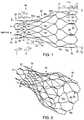
- FIGS. 1-2are, respectively, side and perspective views of an exemplary stent structure in an expanded state.
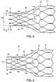
- FIG. 3is a side view illustrating the stent structure of FIGS. 1-2 in a compressed state.
- FIG. 4is a side view of an exemplary integral barb of the stent structure of FIGS. 1-2 .
- FIGS. 5-6are perspective views of an exemplary aortic valve when no forces are imposed upon the valve.
- FIG. 7is a perspective view the aortic valve of FIGS. 5-6 during systole.
- FIGS. 8-9are side views illustrating a technique for coupling the aortic valve of FIGS. 5-7 to the stent structure of FIGS. 1-3 .
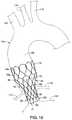
- FIG. 10is a schematic showing the aortic prosthesis of FIG. 9 disposed within a patient's anatomy.
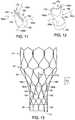
- FIGS. 11-12are, respectively, perspective views of an aortic valve comprising suspension ties when no forces are imposed and during diastole.
- FIG. 13is a side view illustrating coupling of the aortic valve of FIGS. 11-12 to the stent structure of FIGS. 1-3 .
- FIGS. 14-16are, respectively, perspective views illustrating an aortic valve comprising reinforcement strips when no forces are imposed, during systole and during diastole.
- FIGS. 17-19illustrate aortic valves comprising one or more alternative reinforcement strips.
- proximalrefers to a direction that is generally closest to the heart during a medical procedure
- distalrefers to a direction that is furthest from the heart during a medical procedure
- FIGS. 1-2a first embodiment of a stent structure 20 , which may be used in conjunction with an aortic valve prosthesis, is shown and described.
- the stent structure 20may be used in conjunction with an aortic valve 120 to form a completed aortic valve prosthesis 10 as shown in FIG. 9 below.
- the stent structure 20has a collapsed delivery state and an expanded deployed state, and generally comprises a proximal region 30 , a tapered region 50 , and a distal region 70 , as shown in FIGS. 1-2 .
- a pattern of the stent structure 20depicted in a flattened and collapsed state, is shown in FIG. 3 .
- the stent structure 20may be manufactured from a continuous cylinder into which a pattern may be cut by a laser or by chemical etching to produce slits in the wall of the cylinder. The resulting structure may then be heat set to give it a desired final configuration. As shown in FIGS. 1-2 , the final configuration may include a shape having a series of multiple closed cells.
- the proximal region 30 of the stent structure 20comprises a generally cylindrical shape having an expanded outer diameter d 1 .
- the proximal region 30is configured to be disposed at least partially within the aortic sinus, as shown in FIG. 10 below.
- the distal region 70 of the stent structure 20comprises a generally cylindrical shape having an expanded outer diameter d 2 , and is configured to be disposed at least partially within the ascending aorta.
- the tapered region 50generally bridges the change from diameter d 1 to diameter d 2 .
- the proximal region 30 of the stent structure 20may comprise multiple adjacent proximal apices 31 .
- Each proximal apex 31may comprise an end region 32 having an integral barb 33 formed therein, as shown in FIG. 4 .
- the barb 33may be formed by laser cutting a desired barb shape into the end regions 32 .
- a slit 34therefore is formed into each end region 32 after the desired barb shape is formed, as shown in FIG. 4 .
- a main body of the barb 33may be bent in a radially outward direction with respect to the end region 32 .
- the anglemay comprise any acute angle, or alternatively may be substantially orthogonal or obtuse.
- the barb 33may be sharpened, for example, by grinding the tip of the barb, to facilitate engagement at a target tissue site.
- the proximal region 30 of the stent structure 20further may comprise a plurality of closed cells 35 formed by multiple angled strut segments.
- four angled strut segments 36 , 37 , 38 and 39form one closed cell 35 , as shown in FIG. 1 .
- a first proximal apex 31extends distally and splits into first and second angled strut segments 36 and 37 , respectively, which are joined to one another at a junction 41 .
- third and fourth angled strut segments 38 and 39are joined at the junction 41 and extend distally therefrom, as shown in FIG. 1 .
- the angled strut segments 36 - 39 of the cell 35may be compressed such that they are substantially parallel to one another.
- the first and second angled strut segments 36 and 37each generally comprise a length L 1 , and each are generally disposed at an angle ⁇ 1 relative to a longitudinal axis L of the stent structure 20 , as shown in FIG. 1 .
- the third and fourth angled strut segments 38 and 39each generally comprise a length L 2 and each are generally disposed at an angle ⁇ 2 relative to the longitudinal axis L, as shown in FIG. 1 .
- the closed cell 35comprises a total length L 3 , representing the combined lengths L 1 and L 2 , as shown in FIG. 1 .
- the length L 1 of the first and second angled strut segments 36 and 37is greater than the length L 2 of the third and fourth angled strut segments 38 and 39 .
- the length L 1may be about 1.5 to about 4.0 times greater than the length L 2 .
- a cross-sectional area of the first and second angled strut segments 36 and 37may be greater than a cross-sectional area of the third and fourth angled strut segments 38 and 39 .
- the cross-sectional area of the first and second angled strut segments 36 and 37is about 4 times greater than the cross-sectional area of the third and fourth angled strut segments 38 and 39 .
- the increased cross-sectional area of the first and second angled strut segments 36 and 37causes these segments to primarily provide the radial force within the closed cells 35 , while the third and fourth angled strut segments 38 and 39 are mainly intended for connecting adjacent closed cells 35 and 55 a , instead of providing significant radial force.
- the angle ⁇ 2 of the third and fourth angled strut segments 38 and 39is greater than the angle ⁇ 1 of the first and second angled strut segments 36 and 37 . Since the first and second angled strut segments 36 and 37 are primarily providing the radial force, the angle ⁇ 1 is selected to achieve the desired radial force, while as noted above, the third and fourth angled strut segments 38 and 39 are mainly intended for connecting adjacent closed cells 35 and 55 a , and therefore yield a different angle ⁇ 2 for this different primary purpose. In one embodiment, the angle ⁇ 2 may be about 1.2 to 4.0 times greater than the angle ⁇ 1 .
- each closed cell 35comprises a generally spade-shaped configuration, as shown in FIGS. 1-2 .
- the relative lengths and anglesmay be greater or less than depicted and/or provided in the exemplary dimensions disclosed herein.
- the pattern of angled strut segments 36 - 39may be repeated around the circumference of the proximal region 30 of the stent structure 20 .
- the stent structure 20may be formed into a continuous, generally cylindrical shape.
- ten proximal apices 31 and ten closed cells 35are disposed around the circumference of the proximal region 30 , although greater or fewer proximal apices and closed cells may be provided to vary the diameter and/or radial force characteristics of the stent.
- the proximal region 30may be flared slightly relative to the longitudinal axis L. In one example, a proximal end of each apex 31 may be bowed outward relative to a distal end of the same apex 31 . Such a flaring may facilitate engagement with the aortic sinus when implanted.
- the tapered region 50also comprises a plurality of closed cells.
- four different closed cells 55 a , 55 b , 55 c and 55 dare provided along the length of the tapered region 50 .
- Each of the closed cells 55 a - 55 dmay comprise a slightly different shape, as shown in FIGS. 1-2 .
- ten of each series of closed cells 55 a - 55 dare disposed around the circumference of the tapered region 50 , and the diameter of the tapered region 50 increases from the outer diameter d 1 to the outer diameter d 2 .
- the first and second angled strut segments 56 and 57each generally comprise a length L 4 and each are generally disposed at an angle relative to the longitudinal axis L that may be about the same as, or slightly greater or less than, the angle ⁇ 1 .
- the third and fourth angled strut segments 58 and 59each generally comprise a length L 5 and each are generally disposed at an angle relative to the longitudinal axis L that may be about the same as, or slightly greater or less than, the angle ⁇ 2 .
- the closed cell 55 bcomprises a total length L 6 , representing the combined lengths L 4 and L 5 , as shown in FIG. 1 .
- the length L 4 of the first and second angled strut segments 56 and 57is greater than the length L 5 of the third and fourth angled strut segments 58 and 59 .
- the length L 4may be about 1.1 to about 4 times greater than the length L 5 .
- the total length L 6 of the closed cell 55 b of the tapered region 50is greater than the total length L 3 of the closed cell 35 of the proximal region 30 , as shown in FIG. 1 .
- the length of one or more individual struts of the tapered region 50e.g., first and second angled strut segments 56 and 57 having length L 4 , may be longer than the total length L 3 of the closed cell 35 of the proximal region 30 .
- the distal region 70similarly comprises a plurality of closed cells.
- two different closed cells 75 a and 75 bare provided along the length of the distal region 70 .
- the closed cells 75 a and 75 bmay comprise a different shape relative to one another, as shown in FIGS. 1-2 .
- ten of each series of closed cells 75 a and 75 bare disposed around the circumference of the distal region 70 to form the overall outer diameter d 2 .
- the most distal closed cell 75 bcomprises four angled strut segments 76 , 77 , 78 and 79 , as shown in FIG. 1 .
- the first and second angled strut segments 76 and 77each generally comprise a length L 7 and each are generally disposed at an angle relative to the longitudinal axis L that may be about the same as, or slightly greater or less than, the angle ⁇ 1 .
- the third and fourth angled strut segments 78 and 79each generally comprise a length L 9 and each are generally disposed at an angle relative to the longitudinal axis L that may be about the same as, or slightly greater or less than, the angle ⁇ 2 .
- a barbed region 80 having a barb 83is disposed between the angled strut segments, as shown in FIG. 1 .
- the barb 83 of the barbed region 80may be formed integrally in the same manner as the barb 33 of the proximal region 30 , as shown in FIG. 4 , but preferably faces in a proximal direction.
- the barbed region 80is generally parallel to the longitudinal axis L of the stent structure 20 and comprises a length L 8 .
- the cell 55 bcomprises a total length L 10 , representing the combined lengths L 7 , L 8 and L 9 , as shown in FIG. 1 .
- the length L 7 of the first and second angled strut segments 76 and 77is greater than the length L 9 of the third and fourth angled strut segments 78 and 79 .
- the length L 7may be about 1.1 to about 4.0 times greater than the length L 9 .
- the total length L 10 of the closed cell 75 b of the distal region 70is greater than the total length L 6 of the closed cell 55 b of the tapered region 50 , which in turn is greater than the total length L 3 of the closed cell 35 of the proximal region 30 , as shown in FIG. 1 . Therefore, the lengths of individual closed cells increase along the stent structure from a proximal end 22 to a distal end 24 of the stent structure 20 .
- the lengths of individual closed cellsgenerally increase along the stent structure 20 from the proximal end 22 to the distal end 24 , the forces imposed by the stent structure 20 along different regions may be varied for a patient's anatomy. Radial force and stiffness are a function of the individual cell lengths. Therefore, in the example of an aortic valve replacement, a relatively short length L 3 of the closed cell 35 of the proximal region 30 yields a relatively high radial force imposed upon the aortic sinus to allow for an enhanced and rigid attachment at this location.
- a relatively long length L 10 of the closed cell 75 b of the distal region 70yields a relatively low radial force imposed upon the ascending aorta, thereby facilitating a flexible contour at the distal region 70 that does not adversely impact the ascending aorta 105 .
- radial force and stiffnessare a function of the strut angles.
- the individual struts 36 and 37 of the proximal region 30may have a shallower strut angle relative to the individual struts 76 and 77 of the distal region 70 , i.e., the individual struts 36 and 37 may be more perpendicular to the longitudinal axis L of the device. Therefore, the angles of the individual struts 36 and 37 may contribute to a higher radial force at the proximal region 30 relative to the individual struts 76 and 77 of the distal region 70 .
- an increased strut widthmay be provided at the proximal region 30 to promote a higher radial force relative to the strut width at the distal region 70 .
- the stent structure 20has different radial force properties at its proximal and distal regions 30 and 70 that beneficially interact with their associated regions into which they are implanted, e.g., the aortic sinus and the ascending aorta, respectively.
- the lengths of individual cellsmay always increase relative to one another moving in a proximal to distal direction, i.e., each closed cell has an overall length that is greater than a length of every other closed cell that is disposed proximally thereof.
- adjacent cellsmay comprise about the same length, or a proximal cell may comprise a lesser length than an adjacent distal cell. Therefore, while the lengths of individual angled strut segments generally increase in a proximal to distal direction, it is possible that some of the individual angled strut segments of a more distal region may be smaller than a more proximally oriented region.
- Expansion of the stent structure 20is at least partly provided by the angled strut segments, which may be substantially parallel to one another in a compressed state of FIG. 3 , but may tend to bow outward away from one another in the expanded state shown in FIGS. 1-2 .
- the stent structure 20may be formed from any suitable material, and formed from a laser-cut cannula.
- the stent structure 20has a reduced diameter delivery state so that it may be advanced to a target location within a vessel or duct.
- the struts of the stentmay comprise a substantially flat wire profile or may comprise a rounded profile. As best seen in FIGS. 1-2 , the struts of the stent generally comprise a flat wire profile in this example.
- the stent structure 20may be manufactured from a super-elastic material.
- the super-elastic materialmay comprise a shape-memory alloy, such as a nickel titanium alloy (nitinol).
- the stent structure 20comprises a self-expanding material such as nitinol, the stent may be heat-set into the desired expanded state, whereby the stent structure 20 can assume a relaxed configuration in which it assumes the preconfigured first expanded inner diameter upon application of a certain cold or hot medium.
- the stent structure 20may be made from other metals and alloys that allow the stent structure 20 to return to its original, expanded configuration upon deployment, without inducing a permanent strain on the material due to compression.
- the stent structure 20may comprise other materials such as stainless steel, cobalt-chrome alloys, amorphous metals, tantalum, platinum, gold and titanium.
- the stent structure 20also may be made from non-metallic materials, such as thermoplastics and other polymers.
- some foreshortening of the stent structure 20may occur during expansion of the stent from the collapsed configuration of FIG. 3 to the expanded deployed state of FIGS. 1-2 . Since the proximal region 30 of the stent structure 20 is deployed first, it is expected that such foreshortening is not problematic since a precise landing area of the distal region 70 within the ascending aorta is generally not needed, so long as solid contact is achieved.
- the barbs 33 of the proximal region 30are oriented in a distally-facing direction, whereas the barbs 83 of the distal region 70 are oriented in a proximally-facing direction.
- additional or fewer barbsmay be disposed at various locations along the stent structure 20 and may be oriented in the same or different directions.
- integral and/or externally attached barbsmay be used.
- the aortic valve 120generally comprises proximal and distal regions 130 and 170 , respectively, and a tapered region 150 disposed therebetween.
- the aortic valve 120comprises a delivery state in which it may be compressed for percutaneous implantation along with the stent structure 20 , and further comprises different states during systole and diastole. Generally, antegrade flow opens the aortic valve 120 while retrograde flow closes the aortic valve 120 .
- phase of systole for the aortic valve 120depicted in FIG. 7 , blood may flow through the opposing flat surfaces 172 and 174 at the distal end 170 of the aortic valve 120 .
- opposing flat surfaces 172 and 174 at the distal end 170 of the aortic valve 120are generally adjacent to one another to inhibit blood flow back through the valve.
- the proximal region 130generally comprises a cylindrical body having an outer diameter that is approximately equal to, or just less than, an expanded inner diameter of the proximal region 30 of the stent structure 20 .
- the aortic valve 120is disposed generally within the stent structure 20 such that the proximal region 130 is at least partially aligned with the proximal region 30 of the stent structure 20 .
- the tapered region 150 of the aortic valve 120may comprise two opposing flat surfaces 152 and 154 , as shown in FIGS. 5-6 .
- the opposing flat surfaces 152 and 154generally each comprise a proximal portion 156 in the form of a curved area that reduces the diameter of the proximal region 130 , and a distal portion 157 in the form of a wide flat panel that transitions into the distal region 170 , as shown in FIGS. 5-6 .
- the distal region 170 of the aortic valve 120may comprise a generally rectangular profile from an end view, i.e., looking at the device from a distal to proximal direction.
- the distal region 170comprises the opposing flat surfaces 172 and 174 noted above, which are separated by narrower flat sides 175 a and 175 b , as shown in FIGS. 5-6 .
- the opposing flat surfaces 152 and 154 of the tapered region 150generally transition into the opposing flat surfaces 172 and 174 of the distal region 170 , respectively.
- the opposing flat surfaces 152 and 154 of the tapered region 150are angled relative to both the proximal region 130 and the distal region 170 , as shown in FIGS. 5-6 .
- the aortic valve 120may comprise a biocompatible graft material is preferably non-porous so that it does not leak under physiologic forces.
- the graft materialmay be formed of Thoralon® (Thoratec® Corporation, Pleasanton, Calif.), Dacron® (VASCUTEK® Ltd., Renfrewshire, Scotland, UK), a composite thereof, or another suitable material.
- the graft materialis formed without seams.
- the tubular graftcan be made of any other at least substantially biocompatible material including such fabrics as other polyester fabrics, polytetrafluoroethylene (PTFE), expanded PTFE, and other synthetic materials.
- Naturally occurring biomaterialsare also highly desirable, particularly a derived collagen material known as extracellular matrix.
- An element of elasticitymay be incorporated as a property of the fabric or by subsequent treatments such as crimping.
- the aortic valve 120is disposed generally within the stent structure 20 such that the proximal region 130 of the aortic valve 120 is at least partially aligned with the proximal region 30 of the stent structure 20 .
- a proximal attachment portion 132 of the aortic valve 120 having a length xis disposed proximal to the proximal apices 31 of the stent structure 20 , as shown in FIG. 8 , then the proximal attachment portion 132 is folded externally over the proximal apices 31 , as shown in FIG. 9 .
- the proximal attachment portion 132then may be sutured or otherwise attached to the proximal apices 31 and/or any of the angled strut segments 36 - 39 , thereby securing a portion of the aortic valve 120 to the stent structure 20 to form a complete aortic prosthesis 10 , as depicted in FIG. 9 .
- the barbs 33 of the stent structure 20may protrude through the fabric of the proximal attachment portion 132 for engagement with targeted tissue.
- the distal region 170 of the aortic valve 120may extend within the tapered region 50 and/or the distal region 70 of the stent structure 20 , and may be generally centrally disposed therein, although the exact positioning of distal region 170 of the aortic valve 120 relative to the stent structure 20 may be varied as needed.
- one or more reinforcement membersdescribed generally in FIGS. 11-19 below, may be coupled to the aortic valve 120 and/or the stent structure 20 to enhance structural integrity and/or functionality of the aortic prosthesis 10 .
- the distal region 170 of the aortic valve 120is disposed within the tapered region 50 and/or the distal region 70 of the stent structure 20 , which are positioned in the proximal ascending thoracic aorta above (distal to) the annulus and above the native aortic valve.
- Previous valvesare designed to occupy the aortic annulus; however, the unpredictable shape and diameter of the aortic annulus makes the valve unpredictable in shape and diameter, leading to asymmetric replacement valve movement, leakage and reduced durability.
- the distal region 170 of the aortic valve 120by moving the distal region 170 of the aortic valve 120 to a distally spaced-apart location relative to the native aortic valve, i.e., the unpredictable shape and diameter of the aortic annulus have less impact upon the spaced-apart distal region 170 of the aortic valve 120 , and therefore the distal region 170 is less subject to asymmetric valve movement and leakage, and may have increased durability.
- proximal and tapered regions 130 and 150can vary without significantly affecting flow or valve function at the distal region 170 . While the distal region 170 of the valve 120 is shown having a generally rectangular shape, a tricuspid-shaped distal region of the valve may be provided, in which case the tapered region 150 may be omitted or altered to accommodate such a tricuspid-shaped distal region.
- FIG. 10a partial cut-away view of a heart 102 and an aorta 104 are shown.
- the heart 102may comprise an aortic valve 106 that does not seal properly. This defect of the aortic valve 106 allows blood to flow from the aorta 104 back into the left ventricle, leading to a disorder known as aortic regurgitation.
- Also shown in FIG. 10are a brachiocephalic trunk 112 , a left common carotid artery 114 , and a left subclavian artery 116 .
- a portion of the aorta 104 referred to herein as an ascending aorta 105is shown located between the aortic valve 106 and the brachiocephalic trunk 112 .
- a patient's coronary arteries 117 and 118are located distal to the aortic valve 106 .
- the aortic prosthesis 10is introduced into a patient's vascular system, delivered, and deployed using a deployment device, or introducer.
- the deployment devicedelivers and deploys the aortic prosthesis 10 within the aorta at a location to replace the aortic valve 106 , as shown in FIG. 10 .
- the deployment devicemay be configured and sized for endoluminal delivery and deployment through a femoral cut-down.
- the aortic prosthesis 10with the stent structure 20 in a radially collapsed state, may be inserted into a delivery catheter using conventional methods.
- various other componentsmay need to be provided in order to obtain a delivery and deployment system that is optimally suited for its intended purpose.
- Zenith® Thoracic Aortic Aneurysm Endovascular Graftuses a delivery system that is commercially available from Cook Inc., Bloomington, Ind., and may be suitable for delivering and deploying an aortic prosthesis in accordance with the present embodiments.
- a trigger wire release mechanismfor releasing a retained end of the stent structure 20 of the aortic prosthesis 10 .
- the trigger wire arrangementincludes at least one trigger wire extending from a release mechanism through the deployment device, and the trigger wire is engaged with selected locations of the stent structure 20 . Individual control of the deployment of various regions of the stent structure 20 enables better control of the deployment of the aortic prosthesis 10 as a whole.
- stent structure 20is generally described as a self-expanding framework herein, it will be appreciated that a balloon-expandable framework may be employed to accomplish the same functionality. If a balloon-expandable stent structure is employed, then a suitable balloon catheter is employed to deliver the aortic prosthesis as generally outlined above. Optionally, after deployment of a self-expanding stent structure 20 , a relatively short balloon expandable stent may be delivered and deployed inside of the proximal region 30 of the stent structure 20 to provided added fixation at the location of the aortic sinus.
- the aortic prosthesis 10Upon deployment, the aortic prosthesis 10 is positioned as generally shown in FIG. 10 .
- a relatively high radial forceis imposed by the closed cells 35 of the proximal region 30 upon the aortic sinus 106 to allow for an enhanced and rigid attachment at this location.
- a relatively low radial forceis imposed by the closed cells 75 a and 75 b of the distal region 70 upon the ascending aorta 105 , thereby facilitating a flexible contour at the distal region that does not adversely impact the ascending aorta 105 .
- the aortic prosthesis 10When the aortic prosthesis 10 is implanted, sufficient flow into the coronary arteries 117 and 118 is maintained during retrograde flow. In particular, after blood flows through the distal region 170 of the aortic valve 120 , blood is allowed to flow adjacent to the outside of the tapered central region 150 of the aortic valve 120 and into the coronary arteries 117 and 118 , i.e., through the open individual cells of the stent structure 20 .
- the proximal and distal regions 30 and 70may be configured so that the radial forces exerted upon the coronary sinus 105 and the ascending aorta 105 , respectively, are enough to hold the stent structure 20 in place.
- each of the members of the aortic prosthesis 10may vary.
- the size of a preferred prosthetic deviceis determined primarily by the diameter of the vessel lumen (preferably for a healthy valve/lumen combination) at the intended implant site, as well as the desired length of the overall stent and valve device.
- an initial assessment of the location of the natural aortic valve in the patientis determinative of several aspects of the prosthetic design. For example, the location of the natural aortic valve in the patient will determine the dimensions of the stent structure 20 and the aortic valve 120 , the type of valve material selected, and the size of deployment vehicle.
- the aortic valve 120replaces the function of the recipient's native damaged or poorly performing aortic valve.
- the aortic valve 120allows blood flow when the pressure on the proximal side of the aortic valve 120 is greater than pressure on the distal side of the valve.
- the artificial valve 120regulates the unidirectional flow of fluid from the heart into the aorta.
- FIGS. 11-19various reinforcement members are described that may be coupled to the aortic valve 120 and/or the stent structure 20 to enhance structural integrity and/or functionality of the aortic prosthesis 10 .
- the normal, native aortic valveis suspended from above through its attachment to the walls of the coronary sinus, and suspended aortic valves resist the forces created by diastolic pressure on closed leaflets through attachment to downstream support.
- the various reinforcement members of FIGS. 11-19are intended to reinforce the aortic valve 120 , and in particular, prevent in-folding or “prolapse” of the valve during diastole.
- a first embodiment of reinforcement memberscomprises a plurality of suspension ties 180 a - 180 d that are coupled between the tapered region 150 of the aortic valve 120 and the tapered region 50 of the stent structure 20 .
- bloodmay flow through the opposing flat surfaces 172 and 174 at the distal end 170 of the aortic valve 120 , and the suspension ties 180 a - 180 d are relatively slack allowing for normal opening of the aortic valve 120 .
- opposing flat surfaces 172 and 174 at the distal end 170 of the aortic valve 120are generally adjacent to one another to inhibit blood flow back through the valve, while the suspension ties 180 a - 180 d become more taut and prevent prolapse of the aortic valve 120 when retrograde flow is imposed upon the exterior surfaces of the valve, as depicted in the finite element analysis simulation of FIG. 12 .
- the suspension ties 180 a - 180 dadvantageously provide a safety mechanism by which prolapse is avoided during retrograde flow.
- the suspension ties 180 a - 180 dmay be molded into the aortic valve 120 in the manner that fiber reinforcements are molded into a graft structure, and further may be coupled to one or more struts of the stent structure 20 using sutures 198 or another suitable coupling member that does not impede expansion of the stent structure 20 . While first ends of the suspension ties 180 a - 180 d are shown coupled to the tapered region 150 of the aortic valve 120 , they may alternatively, or additionally, be coupled to another location, such as the distal region 170 .
- suspension ties 180 a - 180 dare shown coupled to the tapered region 50 of the stent structure 20 , they may alternatively, or additionally, be coupled to another location, such as the distal region 70 . While four exemplary suspension ties 180 a - 180 d are shown, greater or fewer suspension ties may be used, and their positioning may be varied as noted above, to achieve the desired functionality and reduce potential prolapse of the aortic valve 120 .
- the angles ⁇ 3 of the suspension ties 180 a - 180 d relative to the longitudinal axis L, as shown in FIG. 13may be between about 40-80 degrees when relatively slack. However, it will be appreciated the angles ⁇ 3 may be greater or less than what is depicted in FIG. 13 .
- the suspension ties 180 a - 180 dcomprise a thickness of between about 0.002-0.02 inches, and are molded into a Thoralon® or Dacron® coating. Other materials may be used, so long as the suspension ties 180 a - 180 d are non-thrombogenic, or coated with a non-thrombogenic material.
- the aortic valve 120can therefore be as long as necessary for optimal valve function, even if it is of a simple bicuspid design.
- the length of the aortic valve 120can be varied such that the distal region 170 of the aortic valve 120 is positioned at the desired location within the ascending thoracic aorta spaced-apart from the native aortic annulus.
- a first reinforcement strip 185 agenerally extends between a portion of the proximal region 130 , through one opposing flat surface 152 of the tapered region 150 , and to one opposing flat surface 172 of the distal region 170 , as shown in FIGS. 14-16 .
- a second reinforcement strip 185 bis disposed about 90 degrees apart from the first reinforcement strip 185 a , and generally extends between a portion of the proximal region 130 towards one of the narrower flat sides 175 a .
- a third reinforcement strip 185 cis disposed about 90 degrees apart from the first reinforcement strip 185 a , and generally extends between a portion of the proximal region 130 , through one opposing flat surface 154 of the tapered region 150 , and to one opposing flat surface 174 of the distal region 170 .
- a fourth reinforcement stripis obscured in FIGS. 14-16 but may be disposed about 90 degrees apart from the second reinforcement strip 185 b and is a mirror image thereof.
- opposing flat surfaces 172 and 174 at the distal end 170 of the aortic valve 120are generally adjacent to one another to inhibit blood flow back through the valve, while the reinforcement strips 185 a - 185 d may become bowed radially inward along the tapered region 150 to prevent prolapse of the aortic valve 120 when retrograde flow is imposed upon the exterior surfaces of the valve.
- the reinforcement strips 185 a - 185 cmay snap between the states depicted in FIGS. 15-16 during systole and diastole, respectively, when the associated pressures are imposed upon the aortic valve 120 .
- the reinforcement strips 185 a - 185 cadvantageously provide a safety mechanism by which prolapse is avoided during retrograde flow.
- the reinforcement strips 185 a - 185 c of FIGS. 14-16comprise stainless steel or nitinol, though any suitable material to perform such functions may be used.
- the reinforcement stripsmay comprise a thickness of about 0.002 to about 0.010 inches and may be molded into the material of the aortic valve 120 , or coupled externally thereto.
- FIGS. 17-19various alternative reinforcement strips are depicted.
- at least one elliptical reinforcement strip 190is coupled to a portion of the proximal region 130 of the aortic valve 120 and extends distally into the tapered region 150 , positioned generally between the opposing flat surfaces 152 and 154 of the tapered region 150 .
- a first elliptical reinforcement strip 191is coupled entirely to the flat surface 152 of the tapered region 150
- a second longitudinal reinforcement strip 192extends between the proximal region 130 and tapered region 150 and is positioned generally between the opposing flat surfaces 152 and 154 of the tapered region 150 .
- FIG. 17at least one elliptical reinforcement strip 190 is coupled to a portion of the proximal region 130 of the aortic valve 120 and extends distally into the tapered region 150 , positioned generally between the opposing flat surfaces 152 and 154 of the tapered region 150 .
- a first elliptical reinforcement strip 191is
- a diamond-shaped reinforcement strip 193is coupled between the proximal region 130 and the flat surface 152 of the tapered region 150 .
- the reinforcement strips 190 - 193 of FIGS. 17-19may snap between two states during systole and diastole.
- the reinforcement strips 190 - 193advantageously provide a safety mechanism by which prolapse is avoided during retrograde flow. While various exemplary reinforcement strip shapes and locations are shown in FIGS. 14-19 , the shapes and locations of the reinforcement strips may be varied, and greater or fewer strips may be used, without departing from the spirit of the present embodiments.
- the stent structure 20 shown hereinmay be used in connection with different aortic valves, beside the aortic valve 120 .
- various artificial valve designsmay have two or three membranes, and may be arranged in various shapes including slots and flaps that mimic the natural functionality of an anatomical valve.
- the aortic valve 120 shown hereinmay be used in conjunction with different stent structures.
Landscapes
- Health & Medical Sciences (AREA)
- Engineering & Computer Science (AREA)
- Biomedical Technology (AREA)
- Cardiology (AREA)
- Oral & Maxillofacial Surgery (AREA)
- Transplantation (AREA)
- Heart & Thoracic Surgery (AREA)
- Vascular Medicine (AREA)
- Life Sciences & Earth Sciences (AREA)
- Animal Behavior & Ethology (AREA)
- General Health & Medical Sciences (AREA)
- Public Health (AREA)
- Veterinary Medicine (AREA)
- Prostheses (AREA)
Abstract
Description
Claims (19)
Priority Applications (5)
| Application Number | Priority Date | Filing Date | Title |
|---|---|---|---|
| US15/841,744US10695171B2 (en) | 2010-11-05 | 2017-12-14 | Stent structures for use with valve replacements |
| US16/913,434US11554011B2 (en) | 2010-11-05 | 2020-06-26 | Stent structures for use with valve replacements |
| US16/913,472US11602428B2 (en) | 2010-11-05 | 2020-06-26 | Stent structures for use with valve replacements |
| US18/154,573US11911270B2 (en) | 2010-11-05 | 2023-01-13 | Stent structures for use with valve replacements |
| US18/587,117US12245936B2 (en) | 2010-11-05 | 2024-02-26 | Stent structures for use with valve replacements |
Applications Claiming Priority (3)
| Application Number | Priority Date | Filing Date | Title |
|---|---|---|---|
| US41054010P | 2010-11-05 | 2010-11-05 | |
| US13/286,407US20120116496A1 (en) | 2010-11-05 | 2011-11-01 | Stent structures for use with valve replacements |
| US15/841,744US10695171B2 (en) | 2010-11-05 | 2017-12-14 | Stent structures for use with valve replacements |
Related Parent Applications (1)
| Application Number | Title | Priority Date | Filing Date |
|---|---|---|---|
| US13/286,407ContinuationUS20120116496A1 (en) | 2010-11-05 | 2011-11-01 | Stent structures for use with valve replacements |
Related Child Applications (2)
| Application Number | Title | Priority Date | Filing Date |
|---|---|---|---|
| US16/913,472ContinuationUS11602428B2 (en) | 2010-11-05 | 2020-06-26 | Stent structures for use with valve replacements |
| US16/913,434ContinuationUS11554011B2 (en) | 2010-11-05 | 2020-06-26 | Stent structures for use with valve replacements |
Publications (2)
| Publication Number | Publication Date |
|---|---|
| US20180104054A1 US20180104054A1 (en) | 2018-04-19 |
| US10695171B2true US10695171B2 (en) | 2020-06-30 |
Family
ID=45444504
Family Applications (6)
| Application Number | Title | Priority Date | Filing Date |
|---|---|---|---|
| US13/286,407AbandonedUS20120116496A1 (en) | 2010-11-05 | 2011-11-01 | Stent structures for use with valve replacements |
| US15/841,744Active2032-05-02US10695171B2 (en) | 2010-11-05 | 2017-12-14 | Stent structures for use with valve replacements |
| US16/913,472Active2032-09-24US11602428B2 (en) | 2010-11-05 | 2020-06-26 | Stent structures for use with valve replacements |
| US16/913,434Active2032-09-24US11554011B2 (en) | 2010-11-05 | 2020-06-26 | Stent structures for use with valve replacements |
| US18/154,573ActiveUS11911270B2 (en) | 2010-11-05 | 2023-01-13 | Stent structures for use with valve replacements |
| US18/587,117ActiveUS12245936B2 (en) | 2010-11-05 | 2024-02-26 | Stent structures for use with valve replacements |
Family Applications Before (1)
| Application Number | Title | Priority Date | Filing Date |
|---|---|---|---|
| US13/286,407AbandonedUS20120116496A1 (en) | 2010-11-05 | 2011-11-01 | Stent structures for use with valve replacements |
Family Applications After (4)
| Application Number | Title | Priority Date | Filing Date |
|---|---|---|---|
| US16/913,472Active2032-09-24US11602428B2 (en) | 2010-11-05 | 2020-06-26 | Stent structures for use with valve replacements |
| US16/913,434Active2032-09-24US11554011B2 (en) | 2010-11-05 | 2020-06-26 | Stent structures for use with valve replacements |
| US18/154,573ActiveUS11911270B2 (en) | 2010-11-05 | 2023-01-13 | Stent structures for use with valve replacements |
| US18/587,117ActiveUS12245936B2 (en) | 2010-11-05 | 2024-02-26 | Stent structures for use with valve replacements |
Country Status (4)
| Country | Link |
|---|---|
| US (6) | US20120116496A1 (en) |
| EP (1) | EP2489331B1 (en) |
| JP (1) | JP6105196B2 (en) |
| AU (1) | AU2011244968B2 (en) |
Cited By (1)
| Publication number | Priority date | Publication date | Assignee | Title |
|---|---|---|---|---|
| US20210315690A1 (en)* | 2020-04-10 | 2021-10-14 | St. Jude Medical, Cardiology Division, Inc. | Collapsible Leaflets For Prosthetic Heart Valves |
Families Citing this family (87)
| Publication number | Priority date | Publication date | Assignee | Title |
|---|---|---|---|---|
| DE102005003632A1 (en) | 2005-01-20 | 2006-08-17 | Fraunhofer-Gesellschaft zur Förderung der angewandten Forschung e.V. | Catheter for the transvascular implantation of heart valve prostheses |
| US20070213813A1 (en) | 2005-12-22 | 2007-09-13 | Symetis Sa | Stent-valves for valve replacement and associated methods and systems for surgery |
| US7896915B2 (en) | 2007-04-13 | 2011-03-01 | Jenavalve Technology, Inc. | Medical device for treating a heart valve insufficiency |
| DE202008018557U1 (en) | 2007-08-21 | 2015-10-26 | Symetis Sa | A replacement flap |
| EP2679198B1 (en)* | 2007-10-25 | 2021-03-24 | Symetis SA | Valved-stents and systems for delivery thereof |
| BR112012021347A2 (en) | 2008-02-26 | 2019-09-24 | Jenavalve Tecnology Inc | stent for positioning and anchoring a valve prosthesis at an implantation site in a patient's heart |
| US9044318B2 (en) | 2008-02-26 | 2015-06-02 | Jenavalve Technology Gmbh | Stent for the positioning and anchoring of a valvular prosthesis |
| US20090276040A1 (en)* | 2008-05-01 | 2009-11-05 | Edwards Lifesciences Corporation | Device and method for replacing mitral valve |
| AU2009261580B2 (en)* | 2008-06-20 | 2016-01-28 | Coloplast A/S | Esophageal valve |
| BR112012010321B8 (en) | 2009-11-02 | 2021-06-22 | Symetis Sa | replacement valve for use on a human body |
| US8449599B2 (en)* | 2009-12-04 | 2013-05-28 | Edwards Lifesciences Corporation | Prosthetic valve for replacing mitral valve |
| US8579964B2 (en) | 2010-05-05 | 2013-11-12 | Neovasc Inc. | Transcatheter mitral valve prosthesis |
| US10856978B2 (en) | 2010-05-20 | 2020-12-08 | Jenavalve Technology, Inc. | Catheter system |
| WO2011147849A1 (en) | 2010-05-25 | 2011-12-01 | Jenavalve Technology Inc. | Prosthetic heart valve and transcatheter delivered endoprosthesis comprising a prosthetic heart valve and a stent |
| US20120116496A1 (en) | 2010-11-05 | 2012-05-10 | Chuter Timothy A | Stent structures for use with valve replacements |
| US9744033B2 (en) | 2011-04-01 | 2017-08-29 | W.L. Gore & Associates, Inc. | Elastomeric leaflet for prosthetic heart valves |
| US9554897B2 (en) | 2011-04-28 | 2017-01-31 | Neovasc Tiara Inc. | Methods and apparatus for engaging a valve prosthesis with tissue |
| US9308087B2 (en) | 2011-04-28 | 2016-04-12 | Neovasc Tiara Inc. | Sequentially deployed transcatheter mitral valve prosthesis |
| US10285798B2 (en) | 2011-06-03 | 2019-05-14 | Merit Medical Systems, Inc. | Esophageal stent |
| US9554806B2 (en) | 2011-09-16 | 2017-01-31 | W. L. Gore & Associates, Inc. | Occlusive devices |
| US8986368B2 (en) | 2011-10-31 | 2015-03-24 | Merit Medical Systems, Inc. | Esophageal stent with valve |
| US20130274873A1 (en) | 2012-03-22 | 2013-10-17 | Symetis Sa | Transcatheter Stent-Valves and Methods, Systems and Devices for Addressing Para-Valve Leakage |
| US11207176B2 (en) | 2012-03-22 | 2021-12-28 | Boston Scientific Scimed, Inc. | Transcatheter stent-valves and methods, systems and devices for addressing para-valve leakage |
| US9345573B2 (en) | 2012-05-30 | 2016-05-24 | Neovasc Tiara Inc. | Methods and apparatus for loading a prosthesis onto a delivery system |
| KR102313261B1 (en) | 2012-06-05 | 2021-10-14 | 메리트 메디컬 시스템즈, 인크. | Esophageal stent |
| US9283072B2 (en) | 2012-07-25 | 2016-03-15 | W. L. Gore & Associates, Inc. | Everting transcatheter valve and methods |
| US10376360B2 (en) | 2012-07-27 | 2019-08-13 | W. L. Gore & Associates, Inc. | Multi-frame prosthetic valve apparatus and methods |
| US20140142693A1 (en)* | 2012-11-20 | 2014-05-22 | Medtronic, Inc | Valve Prosthesis Frames |
| US9968443B2 (en) | 2012-12-19 | 2018-05-15 | W. L. Gore & Associates, Inc. | Vertical coaptation zone in a planar portion of prosthetic heart valve leaflet |
| US10966820B2 (en) | 2012-12-19 | 2021-04-06 | W. L. Gore & Associates, Inc. | Geometric control of bending character in prosthetic heart valve leaflets |
| US9737398B2 (en) | 2012-12-19 | 2017-08-22 | W. L. Gore & Associates, Inc. | Prosthetic valves, frames and leaflets and methods thereof |
| US9144492B2 (en) | 2012-12-19 | 2015-09-29 | W. L. Gore & Associates, Inc. | Truncated leaflet for prosthetic heart valves, preformed valve |
| US10321986B2 (en) | 2012-12-19 | 2019-06-18 | W. L. Gore & Associates, Inc. | Multi-frame prosthetic heart valve |
| US10039638B2 (en) | 2012-12-19 | 2018-08-07 | W. L. Gore & Associates, Inc. | Geometric prosthetic heart valves |
| US9101469B2 (en) | 2012-12-19 | 2015-08-11 | W. L. Gore & Associates, Inc. | Prosthetic heart valve with leaflet shelving |
| EP2964148A4 (en) | 2013-03-05 | 2016-08-24 | Merit Medical Systems Inc | REINFORCED VALVE |
| WO2014150130A1 (en) | 2013-03-15 | 2014-09-25 | Merit Medical Systems, Inc. | Esophageal stent |
| CN105473105B (en) | 2013-03-15 | 2019-03-22 | 心脏结构导航公司 | Catheter-guided valve replacement device and method |
| KR20150130300A (en)* | 2013-03-15 | 2015-11-23 | 더블유.엘. 고어 앤드 어소시에이트스, 인코포레이티드 | Improved leaflet and valve apparatus |
| US9572665B2 (en) | 2013-04-04 | 2017-02-21 | Neovasc Tiara Inc. | Methods and apparatus for delivering a prosthetic valve to a beating heart |
| US11911258B2 (en) | 2013-06-26 | 2024-02-27 | W. L. Gore & Associates, Inc. | Space filling devices |
| CN105491978A (en) | 2013-08-30 | 2016-04-13 | 耶拿阀门科技股份有限公司 | Radially collapsible frame for a prosthetic valve and method for manufacturing such a frame |
| US9504565B2 (en) | 2013-12-06 | 2016-11-29 | W. L. Gore & Associates, Inc. | Asymmetric opening and closing prosthetic valve leaflet |
| US9750603B2 (en) | 2014-01-27 | 2017-09-05 | Medtronic Vascular Galway | Stented prosthetic heart valve with variable stiffness and methods of use |
| US10117763B2 (en)* | 2014-03-18 | 2018-11-06 | Boston Scientific Scimed, Inc. | Reduced granulation and inflammation stent design |
| DE102014205366B4 (en)* | 2014-03-21 | 2019-03-28 | Coloplast A/S | Catch wire instrument with catch wire structure made of tubular piece |
| AU2015277089B2 (en)* | 2014-06-18 | 2017-11-02 | Boston Scientific Scimed, Inc. | Biliary stent |
| BR112017003339A2 (en) | 2014-08-18 | 2017-11-28 | Gore & Ass | integral seamed structure for protective valves |
| US9827094B2 (en) | 2014-09-15 | 2017-11-28 | W. L. Gore & Associates, Inc. | Prosthetic heart valve with retention elements |
| EP3270825B1 (en) | 2015-03-20 | 2020-04-22 | JenaValve Technology, Inc. | Heart valve prosthesis delivery system |
| US10709555B2 (en) | 2015-05-01 | 2020-07-14 | Jenavalve Technology, Inc. | Device and method with reduced pacemaker rate in heart valve replacement |
| CA2986047C (en) | 2015-05-14 | 2020-11-10 | W. L. Gore & Associates, Inc. | Devices and methods for occlusion of an atrial appendage |
| CA3007660A1 (en) | 2015-12-15 | 2017-06-22 | Neovasc Tiara Inc. | Transseptal delivery system |
| US10433952B2 (en) | 2016-01-29 | 2019-10-08 | Neovasc Tiara Inc. | Prosthetic valve for avoiding obstruction of outflow |
| WO2017195125A1 (en) | 2016-05-13 | 2017-11-16 | Jenavalve Technology, Inc. | Heart valve prosthesis delivery system and method for delivery of heart valve prosthesis with introducer sheath and loading system |
| DE102016110410B4 (en)* | 2016-06-06 | 2023-03-02 | Acandis Gmbh | Stent, manufacturing process and treatment system |
| CA3042588A1 (en) | 2016-11-21 | 2018-05-24 | Neovasc Tiara Inc. | Methods and systems for rapid retraction of a transcatheter heart valve delivery system |
| US11628056B2 (en) | 2016-11-22 | 2023-04-18 | Cook Medical Technologies Llc | Graft for treating the distal aortic arch and descending aorta in type a patients |
| WO2018138658A1 (en) | 2017-01-27 | 2018-08-02 | Jenavalve Technology, Inc. | Heart valve mimicry |
| GB2563880B (en) | 2017-06-28 | 2022-03-23 | Cook Medical Technologies Llc | Implantable medical device including valve member |
| CA3073834A1 (en) | 2017-08-25 | 2019-02-28 | Neovasc Tiara Inc. | Sequentially deployed transcatheter mitral valve prosthesis |
| WO2019055577A1 (en) | 2017-09-12 | 2019-03-21 | W. L. Gore & Associates, Inc. | Leaflet frame attachment for prosthetic valves |
| CN111163728B (en) | 2017-09-27 | 2022-04-29 | W.L.戈尔及同仁股份有限公司 | Prosthetic valve with mechanically coupled leaflets |
| CN111132636B (en)* | 2017-09-27 | 2022-04-08 | W.L.戈尔及同仁股份有限公司 | Prosthetic valve with expandable frame and related systems and methods |
| US11090153B2 (en) | 2017-10-13 | 2021-08-17 | W. L. Gore & Associates, Inc. | Telescoping prosthetic valve and delivery system |
| US11173023B2 (en) | 2017-10-16 | 2021-11-16 | W. L. Gore & Associates, Inc. | Medical devices and anchors therefor |
| EP3703618A1 (en) | 2017-10-31 | 2020-09-09 | W. L. Gore & Associates, Inc. | Prosthetic heart valve |
| CN111295158A (en) | 2017-10-31 | 2020-06-16 | W.L.戈尔及同仁股份有限公司 | Medical valve and valve leaflet for promoting tissue ingrowth |
| US11154397B2 (en) | 2017-10-31 | 2021-10-26 | W. L. Gore & Associates, Inc. | Jacket for surgical heart valve |
| JP7072062B2 (en) | 2017-10-31 | 2022-05-19 | ダブリュ.エル.ゴア アンド アソシエイツ,インコーポレイティド | Transcatheter placement system and related methods |
| KR20210082188A (en)* | 2018-10-19 | 2021-07-02 | 에드워즈 라이프사이언시스 코포레이션 | Artificial heart valve with non-cylindrical frame |
| USD926322S1 (en) | 2018-11-07 | 2021-07-27 | W. L. Gore & Associates, Inc. | Heart valve cover |
| CN113271890B (en) | 2018-11-08 | 2024-08-30 | 内奥瓦斯克迪亚拉公司 | Ventricular deployment of transcatheter mitral valve prosthesis |
| WO2020150378A1 (en)* | 2019-01-17 | 2020-07-23 | Edwards Lifesciences Corporation | Frame for prosthetic heart valve |
| AU2020211601B2 (en)* | 2019-01-24 | 2023-08-17 | Shockwave Medical, Inc. | Flow modifying implants |
| US11497601B2 (en) | 2019-03-01 | 2022-11-15 | W. L. Gore & Associates, Inc. | Telescoping prosthetic valve with retention element |
| CA3132873A1 (en) | 2019-03-08 | 2020-09-17 | Neovasc Tiara Inc. | Retrievable prosthesis delivery system |
| CA3135753C (en) | 2019-04-01 | 2023-10-24 | Neovasc Tiara Inc. | Controllably deployable prosthetic valve |
| US11491006B2 (en) | 2019-04-10 | 2022-11-08 | Neovasc Tiara Inc. | Prosthetic valve with natural blood flow |
| US11779742B2 (en) | 2019-05-20 | 2023-10-10 | Neovasc Tiara Inc. | Introducer with hemostasis mechanism |
| JP7520897B2 (en) | 2019-06-20 | 2024-07-23 | ニオバスク ティアラ インコーポレイテッド | Thin prosthetic mitral valve |
| US12011349B2 (en) | 2020-03-04 | 2024-06-18 | Medtronic, Inc. | Balloon expandable stent with lengthened commissure posts for transcatheter implantation of a cardiac valve prosthesis |
| EP4138728A1 (en)* | 2020-04-23 | 2023-03-01 | W.L. Gore & Associates Inc. | Valved conduit prostheses |
| AU2022231082A1 (en) | 2021-03-01 | 2023-09-21 | Endovascular Engineering, Inc. | Aspiration devices for treatment of thrombosis including expandable distal ends and systems and methods thereof |
| GB2607878B (en) | 2021-06-10 | 2024-07-10 | Cook Medical Technologies Llc | Implantable medical device and assembly |
| US12053192B2 (en) | 2022-09-01 | 2024-08-06 | Endovascular Engineering, Inc. | Systems, devices, and methods for aspiration, including expandable structures and rotatable shafts |
| WO2024102411A1 (en) | 2022-11-09 | 2024-05-16 | Jenavalve Technology, Inc. | Catheter system for sequential deployment of an expandable implant |
Citations (117)
| Publication number | Priority date | Publication date | Assignee | Title |
|---|---|---|---|---|
| JPS495434B1 (en) | 1969-06-12 | 1974-02-07 | ||
| US4222126A (en) | 1978-12-14 | 1980-09-16 | The United States Of America As Represented By The Secretary Of The Department Of Health, Education & Welfare | Unitized three leaflet heart valve |
| US4994077A (en) | 1989-04-21 | 1991-02-19 | Dobben Richard L | Artificial heart valve for implantation in a blood vessel |
| US5163953A (en) | 1992-02-10 | 1992-11-17 | Vince Dennis J | Toroidal artificial heart valve stent |
| US5332402A (en) | 1992-05-12 | 1994-07-26 | Teitelbaum George P | Percutaneously-inserted cardiac valve |
| US5370685A (en) | 1991-07-16 | 1994-12-06 | Stanford Surgical Technologies, Inc. | Endovascular aortic valve replacement |
| US5397351A (en) | 1991-05-13 | 1995-03-14 | Pavcnik; Dusan | Prosthetic valve for percutaneous insertion |
| US5755782A (en) | 1991-01-24 | 1998-05-26 | Autogenics | Stents for autologous tissue heart valve |
| US5840081A (en) | 1990-05-18 | 1998-11-24 | Andersen; Henning Rud | System and method for implanting cardiac valves |
| US5855597A (en) | 1997-05-07 | 1999-01-05 | Iowa-India Investments Co. Limited | Stent valve and stent graft for percutaneous surgery |
| US5855600A (en) | 1997-08-01 | 1999-01-05 | Inflow Dynamics Inc. | Flexible implantable stent with composite design |
| US5938687A (en) | 1997-06-20 | 1999-08-17 | Ela Medical S.A. | Methods and apparatus for processing troubles of the atrial rhythm |
| US5938697A (en) | 1998-03-04 | 1999-08-17 | Scimed Life Systems, Inc. | Stent having variable properties |
| WO2000021463A1 (en) | 1998-10-13 | 2000-04-20 | Ventrica, Inc. | Devices and methods for use in performing transmyocardial coronary bypass |
| WO2000041652A1 (en) | 1999-01-12 | 2000-07-20 | Brice Letac | Prosthetic heart valve implantable by catheter insertion or surgically |
| US6120534A (en) | 1997-10-29 | 2000-09-19 | Ruiz; Carlos E. | Endoluminal prosthesis having adjustable constriction |
| US6168619B1 (en) | 1998-10-16 | 2001-01-02 | Quanam Medical Corporation | Intravascular stent having a coaxial polymer member and end sleeves |
| US6245102B1 (en) | 1997-05-07 | 2001-06-12 | Iowa-India Investments Company Ltd. | Stent, stent graft and stent valve |
| US6254642B1 (en) | 1997-12-09 | 2001-07-03 | Thomas V. Taylor | Perorally insertable gastroesophageal anti-reflux valve prosthesis and tool for implantation thereof |
| US6258120B1 (en) | 1997-12-23 | 2001-07-10 | Embol-X, Inc. | Implantable cerebral protection device and methods of use |
| WO2001049213A2 (en) | 1999-12-31 | 2001-07-12 | Advanced Bio Prosthetic Surfaces, Ltd. | Endoluminal cardiac and venous valve prostheses and methods of manufacture and delivery thereof |
| US20020055772A1 (en) | 2000-06-26 | 2002-05-09 | Rex Medical | Vascular device with valve for approximating vessel wall |
| US6409756B1 (en) | 2000-01-24 | 2002-06-25 | Edward G. Murphy | Endovascular aortic graft |
| US6416544B2 (en) | 1998-11-11 | 2002-07-09 | Actment Co., Ltd. | Stent manufacturing method thereof and indwelling method thereof |
| US6440164B1 (en) | 1999-10-21 | 2002-08-27 | Scimed Life Systems, Inc. | Implantable prosthetic valve |
| US6482228B1 (en) | 2000-11-14 | 2002-11-19 | Troy R. Norred | Percutaneous aortic valve replacement |
| EP1264582A2 (en) | 2001-06-05 | 2002-12-11 | M.I. Tech Co., Ltd. | Medical stent |
| US6494090B1 (en) | 1998-05-05 | 2002-12-17 | Pierburg Ag | Air-mass sensor |
| WO2003003943A2 (en) | 2001-07-03 | 2003-01-16 | Advanced Bio Prosthetic Surfaces, Ltd | Valvular prostheses having metal or pseudometallic construction and methods of manufacture |
| US20030040792A1 (en) | 2000-09-12 | 2003-02-27 | Shlomo Gabbay | Heart valve prosthesis and sutureless implantation of a heart valve prosthesis |
| US20030074052A1 (en) | 1997-01-24 | 2003-04-17 | Jomed Gmbh | Bistable spring construction for a stent and other medical apparatus |
| US20030120333A1 (en) | 2001-12-20 | 2003-06-26 | The Cleveland Clinic Foundation | Furcated endovascular prosthesis |
| US20030130726A1 (en) | 1999-09-10 | 2003-07-10 | Thorpe Patricia E. | Combination valve and stent for treating vascular reflux |
| US20030176914A1 (en) | 2003-01-21 | 2003-09-18 | Rabkin Dmitry J. | Multi-segment modular stent and methods for manufacturing stents |
| US20030199967A1 (en) | 2002-03-25 | 2003-10-23 | Cook Incorporated | Bifurcated/branch vessel prosthesis |
| JP2004500189A (en) | 2000-01-31 | 2004-01-08 | クック・バイオテック・インコーポレーテッド | Stent valve and method of using the same |
| US20040044402A1 (en) | 2002-09-03 | 2004-03-04 | M.I. Tech Co., Ltd. | Stent and method for manufacturing the same |
| US20040055606A1 (en) | 2001-03-02 | 2004-03-25 | Emphasys Medical, Inc. | Bronchial flow control devices with membrane seal |
| US6730118B2 (en) | 2001-10-11 | 2004-05-04 | Percutaneous Valve Technologies, Inc. | Implantable prosthetic valve |
| US20040117003A1 (en) | 2002-05-28 | 2004-06-17 | The Cleveland Clinic Foundation | Minimally invasive treatment system for aortic aneurysms |
| US6773454B2 (en) | 2000-08-02 | 2004-08-10 | Michael H. Wholey | Tapered endovascular stent graft and method of treating abdominal aortic aneurysms and distal iliac aneurysms |
| US6773453B2 (en) | 1995-01-31 | 2004-08-10 | Scimed Life Systems, Inc. | Method and apparatus for intraluminally implanting an endovascular aortic graft |
| US6797000B2 (en) | 1999-01-27 | 2004-09-28 | Carbomedics Inc. | Tri-composite, full root, stentless valve |
| US20040210304A1 (en) | 1999-11-17 | 2004-10-21 | Corevalve, S.A. | Prosthetic valve for transluminal delivery |
| US20040236411A1 (en) | 2001-07-19 | 2004-11-25 | The Cleveland Clinic Foundation | Prosthetic cardiac valve and method for making same |
| US6830584B1 (en) | 1999-11-17 | 2004-12-14 | Jacques Seguin | Device for replacing a cardiac valve by percutaneous route |
| US20040254636A1 (en) | 2003-05-28 | 2004-12-16 | Flagle Jacob A. | Prosthetic valve with vessel engaging member |
| WO2005011535A2 (en) | 2003-07-31 | 2005-02-10 | Cook Incorporated | Prosthetic valve for implantation in a body vessel |
| US20050075725A1 (en) | 2003-10-02 | 2005-04-07 | Rowe Stanton J. | Implantable prosthetic valve with non-laminar flow |
| US20050102018A1 (en) | 2003-11-06 | 2005-05-12 | Carpenter Judith T. | Endovascular prosthesis, system and method |
| JP2005514968A (en) | 2001-06-08 | 2005-05-26 | レックス メディカル リミテッド パートナーシップ | Vascular device with valve proximate to vessel wall |
| US20050137682A1 (en) | 2003-12-22 | 2005-06-23 | Henri Justino | Stent mounted valve |
| US6911040B2 (en) | 2002-01-24 | 2005-06-28 | Cordis Corporation | Covered segmented stent |
| US20050182483A1 (en) | 2004-02-11 | 2005-08-18 | Cook Incorporated | Percutaneously placed prosthesis with thromboresistant valve portion |
| US20050222674A1 (en) | 2004-03-31 | 2005-10-06 | Med Institute, Inc. | Endoluminal graft with a prosthetic valve |
| US20050251251A1 (en) | 1996-12-31 | 2005-11-10 | Alain Cribier | Valve prosthesis for implantation in body channels |
| US7018406B2 (en) | 1999-11-17 | 2006-03-28 | Corevalve Sa | Prosthetic valve for transluminal delivery |
| US20060149360A1 (en) | 2003-07-08 | 2006-07-06 | Ventor Technologies Ltd. | Fluid flow prosthetic device |
| US20060195180A1 (en) | 2005-02-25 | 2006-08-31 | Arash Kheradvar | Implantable small percutaneous valve and methods of delivery |
| CN2817764Y (en) | 2006-01-16 | 2006-09-20 | 孔祥清 | Transcutaneous active pulse valvular displacing device |
| US20060265056A1 (en) | 2005-05-13 | 2006-11-23 | Corevalve, Inc. | Heart valve prosthesis and methods of manufacture and use |
| WO2006127765A1 (en) | 2005-05-24 | 2006-11-30 | Corevalve, Inc. | A non-cylindrical prosthetic valve system for transluminal delivery |
| US20060276813A1 (en) | 2005-05-20 | 2006-12-07 | The Cleveland Clinic Foundation | Apparatus and methods for repairing the function of a diseased valve and method for making same |
| US7192442B2 (en) | 1999-06-30 | 2007-03-20 | Edwards Lifesciences Ag | Method and device for treatment of mitral insufficiency |
| US7220274B1 (en) | 2003-03-21 | 2007-05-22 | Quinn Stephen F | Intravascular stent grafts and methods for deploying the same |
| US20070118209A1 (en) | 2000-10-26 | 2007-05-24 | Strecker Ernst P | Implantable valve system |
| US20070123972A1 (en) | 2001-03-28 | 2007-05-31 | Cook Incorporated | Modular stent graft assembly and use thereof |
| US20070168013A1 (en) | 2006-01-19 | 2007-07-19 | Myles Douglas | Vascular graft and deployment system |
| US20070173926A1 (en) | 2005-12-09 | 2007-07-26 | Bobo Donald E Jr | Anchoring system for medical implant |
| US20070213813A1 (en) | 2005-12-22 | 2007-09-13 | Symetis Sa | Stent-valves for valve replacement and associated methods and systems for surgery |
| US20070239273A1 (en) | 2006-04-06 | 2007-10-11 | Medtronic Vascular | Riveted Stent Valve For Percutaneous Use |
| US20070244546A1 (en) | 2006-04-18 | 2007-10-18 | Medtronic Vascular, Inc. | Stent Foundation for Placement of a Stented Valve |
| US7329279B2 (en) | 2003-12-23 | 2008-02-12 | Sadra Medical, Inc. | Methods and apparatus for endovascularly replacing a patient's heart valve |
| US20080039891A1 (en) | 2004-01-22 | 2008-02-14 | Rex Medical | Vein filter |
| US7351256B2 (en) | 2002-05-10 | 2008-04-01 | Cordis Corporation | Frame based unidirectional flow prosthetic implant |
| US20080082166A1 (en) | 2006-09-28 | 2008-04-03 | Mikolaj Styrc | Implant which is intended to be placed in a blood vessel |
| US7381219B2 (en) | 2003-12-23 | 2008-06-03 | Sadra Medical, Inc. | Low profile heart valve and delivery system |
| WO2008070797A2 (en) | 2006-12-06 | 2008-06-12 | Medtronic Corevalve, Inc. | System and method for transapical delivery of an annulus anchored self-expanding valve |
| US20080208314A1 (en) | 2007-02-22 | 2008-08-28 | Wilson-Cook Medical Inc. | Prosthesis having a sleeve valve |
| US20080208325A1 (en) | 2007-02-27 | 2008-08-28 | Boston Scientific Scimed, Inc. | Medical articles for long term implantation |
| US7429269B2 (en) | 2003-07-08 | 2008-09-30 | Ventor Technologies Ltd. | Aortic prosthetic devices |
| US20080262593A1 (en) | 2007-02-15 | 2008-10-23 | Ryan Timothy R | Multi-layered stents and methods of implanting |
| US7510574B2 (en) | 2003-07-29 | 2009-03-31 | Pfm, Produkte Fur Die Medizin Ag | Implantable device as organ valve replacement |
| US20090099649A1 (en) | 2007-10-04 | 2009-04-16 | Chobotov Michael V | Modular vascular graft for low profile percutaneous delivery |
| US20090125098A1 (en) | 2007-11-09 | 2009-05-14 | Cook Incorporated | Aortic valve stent graft |
| US7544206B2 (en) | 2001-06-29 | 2009-06-09 | Medtronic, Inc. | Method and apparatus for resecting and replacing an aortic valve |
| US20090171437A1 (en) | 2007-12-26 | 2009-07-02 | Cook Incorporated | Low profile non-symmetrical stent |
| US7556643B2 (en) | 2002-07-24 | 2009-07-07 | Boston Scientific Scimed, Inc. | Graft inside stent |
| US20090198324A1 (en) | 2006-06-01 | 2009-08-06 | Mor Research Applications Ltd. | Methods and devices for treatment of cardiac valves |
| US7572286B1 (en) | 2002-05-13 | 2009-08-11 | Advanced Cardiovascular Systems, Inc. | Stent assembly for the treatment of vulnerable plaque |
| WO2010008549A1 (en) | 2008-07-15 | 2010-01-21 | St. Jude Medical, Inc. | Axially anchoring collapsible and re-expandable prosthetic heart valves for various disease states |
| US7682390B2 (en) | 2001-07-31 | 2010-03-23 | Medtronic, Inc. | Assembly for setting a valve prosthesis in a corporeal duct |
| US20100094411A1 (en) | 2008-10-13 | 2010-04-15 | Vector Technologies, Ltd. | Prosthetic valve having tapered tip when compressed for delivery |
| US20100168839A1 (en) | 2007-06-04 | 2010-07-01 | Braido Peter N | Prosthetic heart valves |
| US7780726B2 (en) | 2001-07-04 | 2010-08-24 | Medtronic, Inc. | Assembly for placing a prosthetic valve in a duct in the body |
| WO2010096176A1 (en) | 2009-02-20 | 2010-08-26 | St. Jude Medical, Inc. | Devices and methods for collapsing prosthetic heart valves |
| WO2010098857A1 (en) | 2009-02-27 | 2010-09-02 | St. Jude Medical, Inc. | Stent features for collapsible prosthetic heart valves |
| WO2010099032A2 (en) | 2009-02-25 | 2010-09-02 | Edwards Lifesciences Corporation | Mitral valve replacement with atrial anchoring |
| US7806920B2 (en) | 2002-04-16 | 2010-10-05 | The International Heart Institute Of Montana Foundation | Sigmoid valve and method for its percutaneous implantation |
| US20100256738A1 (en) | 2009-04-07 | 2010-10-07 | Medtronic Vascular, Inc. | Implantable temporary flow restrictor device |
| US7857845B2 (en) | 2005-02-10 | 2010-12-28 | Sorin Biomedica Cardio S.R.L. | Cardiac-valve prosthesis |
| WO2011025945A1 (en) | 2009-08-27 | 2011-03-03 | Medtronic Inc. | Transcatheter valve delivery systems and methods |
| US7967853B2 (en) | 2007-02-05 | 2011-06-28 | Boston Scientific Scimed, Inc. | Percutaneous valve, system and method |
| US20110208289A1 (en) | 2010-02-25 | 2011-08-25 | Endospan Ltd. | Flexible Stent-Grafts |
| WO2011106544A1 (en) | 2010-02-24 | 2011-09-01 | Medtronic Ventor Technologies Ltd | Mitral prosthesis |
| US8016877B2 (en) | 1999-11-17 | 2011-09-13 | Medtronic Corevalve Llc | Prosthetic valve for transluminal delivery |
| US8092521B2 (en) | 2005-10-28 | 2012-01-10 | Jenavalve Technology, Inc. | Device for the implantation and fixation of prosthetic valves |
| US20120053676A1 (en) | 2009-05-07 | 2012-03-01 | Ku David N | Implantable Prosthetic Vascular Valves |
| WO2012027487A2 (en) | 2010-08-24 | 2012-03-01 | St. Jude Medical, Cardiology Division, Inc. D/B/A St. Jude Medical, Cardiovascular Division | Repositoning of prosthetic heart valve and deployment |
| WO2012039753A2 (en) | 2010-09-20 | 2012-03-29 | St. Jude Medical, Cardiology Division, Inc. | Valve leaflet attachment in collapsible prosthetic valves |
| US20120116498A1 (en) | 2010-11-05 | 2012-05-10 | Chuter Timothy A | Aortic valve prostheses |
| US20120116496A1 (en) | 2010-11-05 | 2012-05-10 | Chuter Timothy A | Stent structures for use with valve replacements |
| US20120130478A1 (en) | 2010-11-16 | 2012-05-24 | Shaw Edward E | Devices and methods for in situ fenestration of a stent-graft at the site of a branch vessel |
| US8206438B2 (en) | 2001-03-23 | 2012-06-26 | Edwards Lifesciences Corporation | Prosthetic heart valve having flared outflow section |
| US8206437B2 (en) | 2001-08-03 | 2012-06-26 | Philipp Bonhoeffer | Implant implantation unit and procedure for implanting the unit |
| US20120283820A1 (en) | 2009-09-18 | 2012-11-08 | The Regents Of The University Of California | Endovascular prosthetic heart valve replacement |
| US8348996B2 (en) | 2006-09-19 | 2013-01-08 | Medtronic Ventor Technologies Ltd. | Valve prosthesis implantation techniques |
Family Cites Families (5)
| Publication number | Priority date | Publication date | Assignee | Title |
|---|---|---|---|---|
| US8728154B2 (en)* | 2007-08-24 | 2014-05-20 | St. Jude Medical, Inc. | Prosthetic aortic heart valves |
| EP2679198B1 (en)* | 2007-10-25 | 2021-03-24 | Symetis SA | Valved-stents and systems for delivery thereof |
| BR112012010321B8 (en) | 2009-11-02 | 2021-06-22 | Symetis Sa | replacement valve for use on a human body |
| KR101702417B1 (en) | 2009-11-09 | 2017-02-06 | 삼성전자주식회사 | Method and apparatus for monopolizing call session of transmitting/receiving call system using universal plug and play |
| EP2444030A1 (en)* | 2010-08-31 | 2012-04-25 | Biotronik AG | Medical valve implant for implantation in an animal body and/or human body |
- 2011
- 2011-11-01USUS13/286,407patent/US20120116496A1/ennot_activeAbandoned
- 2011-11-04EPEP11275139.1Apatent/EP2489331B1/enactiveActive
- 2011-11-04JPJP2011242377Apatent/JP6105196B2/enactiveActive
- 2011-11-04AUAU2011244968Apatent/AU2011244968B2/enactiveActive
- 2017
- 2017-12-14USUS15/841,744patent/US10695171B2/enactiveActive
- 2020
- 2020-06-26USUS16/913,472patent/US11602428B2/enactiveActive
- 2020-06-26USUS16/913,434patent/US11554011B2/enactiveActive
- 2023
- 2023-01-13USUS18/154,573patent/US11911270B2/enactiveActive
- 2024
- 2024-02-26USUS18/587,117patent/US12245936B2/enactiveActive
Patent Citations (145)
| Publication number | Priority date | Publication date | Assignee | Title |
|---|---|---|---|---|
| JPS495434B1 (en) | 1969-06-12 | 1974-02-07 | ||
| US4222126A (en) | 1978-12-14 | 1980-09-16 | The United States Of America As Represented By The Secretary Of The Department Of Health, Education & Welfare | Unitized three leaflet heart valve |
| US4994077A (en) | 1989-04-21 | 1991-02-19 | Dobben Richard L | Artificial heart valve for implantation in a blood vessel |
| US6582462B1 (en) | 1990-05-18 | 2003-06-24 | Heartport, Inc. | Valve prosthesis for implantation in the body and a catheter for implanting such valve prosthesis |
| US5840081A (en) | 1990-05-18 | 1998-11-24 | Andersen; Henning Rud | System and method for implanting cardiac valves |
| US7789909B2 (en) | 1990-05-18 | 2010-09-07 | Edwards Lifesciences Ag | System for implanting a valve prosthesis |
| US5755782A (en) | 1991-01-24 | 1998-05-26 | Autogenics | Stents for autologous tissue heart valve |
| US5397351A (en) | 1991-05-13 | 1995-03-14 | Pavcnik; Dusan | Prosthetic valve for percutaneous insertion |
| US5370685A (en) | 1991-07-16 | 1994-12-06 | Stanford Surgical Technologies, Inc. | Endovascular aortic valve replacement |
| US5163953A (en) | 1992-02-10 | 1992-11-17 | Vince Dennis J | Toroidal artificial heart valve stent |
| US5332402A (en) | 1992-05-12 | 1994-07-26 | Teitelbaum George P | Percutaneously-inserted cardiac valve |
| US6773453B2 (en) | 1995-01-31 | 2004-08-10 | Scimed Life Systems, Inc. | Method and apparatus for intraluminally implanting an endovascular aortic graft |
| US20050251251A1 (en) | 1996-12-31 | 2005-11-10 | Alain Cribier | Valve prosthesis for implantation in body channels |
| US20030074052A1 (en) | 1997-01-24 | 2003-04-17 | Jomed Gmbh | Bistable spring construction for a stent and other medical apparatus |
| US5855597A (en) | 1997-05-07 | 1999-01-05 | Iowa-India Investments Co. Limited | Stent valve and stent graft for percutaneous surgery |
| US6245102B1 (en) | 1997-05-07 | 2001-06-12 | Iowa-India Investments Company Ltd. | Stent, stent graft and stent valve |
| US5938687A (en) | 1997-06-20 | 1999-08-17 | Ela Medical S.A. | Methods and apparatus for processing troubles of the atrial rhythm |
| US5855600A (en) | 1997-08-01 | 1999-01-05 | Inflow Dynamics Inc. | Flexible implantable stent with composite design |
| US6120534A (en) | 1997-10-29 | 2000-09-19 | Ruiz; Carlos E. | Endoluminal prosthesis having adjustable constriction |
| US6254642B1 (en) | 1997-12-09 | 2001-07-03 | Thomas V. Taylor | Perorally insertable gastroesophageal anti-reflux valve prosthesis and tool for implantation thereof |
| US6258120B1 (en) | 1997-12-23 | 2001-07-10 | Embol-X, Inc. | Implantable cerebral protection device and methods of use |
| US5938697A (en) | 1998-03-04 | 1999-08-17 | Scimed Life Systems, Inc. | Stent having variable properties |
| US6494090B1 (en) | 1998-05-05 | 2002-12-17 | Pierburg Ag | Air-mass sensor |
| AU2003234967A1 (en) | 1998-10-13 | 2003-09-11 | Ventrica Inc. | Devices and methods for use in performing transmyocardial coronary bypass |
| WO2000021463A1 (en) | 1998-10-13 | 2000-04-20 | Ventrica, Inc. | Devices and methods for use in performing transmyocardial coronary bypass |
| US6168619B1 (en) | 1998-10-16 | 2001-01-02 | Quanam Medical Corporation | Intravascular stent having a coaxial polymer member and end sleeves |
| US6416544B2 (en) | 1998-11-11 | 2002-07-09 | Actment Co., Ltd. | Stent manufacturing method thereof and indwelling method thereof |
| WO2000041652A1 (en) | 1999-01-12 | 2000-07-20 | Brice Letac | Prosthetic heart valve implantable by catheter insertion or surgically |
| US6797000B2 (en) | 1999-01-27 | 2004-09-28 | Carbomedics Inc. | Tri-composite, full root, stentless valve |
| US7192442B2 (en) | 1999-06-30 | 2007-03-20 | Edwards Lifesciences Ag | Method and device for treatment of mitral insufficiency |
| US20030130726A1 (en) | 1999-09-10 | 2003-07-10 | Thorpe Patricia E. | Combination valve and stent for treating vascular reflux |
| US6440164B1 (en) | 1999-10-21 | 2002-08-27 | Scimed Life Systems, Inc. | Implantable prosthetic valve |
| US7267686B2 (en) | 1999-10-21 | 2007-09-11 | Boston Scientific Scimed, Inc | Implantable prosthetic valve |
| US6830584B1 (en) | 1999-11-17 | 2004-12-14 | Jacques Seguin | Device for replacing a cardiac valve by percutaneous route |
| US8016877B2 (en) | 1999-11-17 | 2011-09-13 | Medtronic Corevalve Llc | Prosthetic valve for transluminal delivery |
| US20040210304A1 (en) | 1999-11-17 | 2004-10-21 | Corevalve, S.A. | Prosthetic valve for transluminal delivery |
| US7892281B2 (en) | 1999-11-17 | 2011-02-22 | Medtronic Corevalve Llc | Prosthetic valve for transluminal delivery |
| US7329278B2 (en) | 1999-11-17 | 2008-02-12 | Corevalve, Inc. | Prosthetic valve for transluminal delivery |
| US7018406B2 (en) | 1999-11-17 | 2006-03-28 | Corevalve Sa | Prosthetic valve for transluminal delivery |
| US6458153B1 (en) | 1999-12-31 | 2002-10-01 | Abps Venture One, Ltd. | Endoluminal cardiac and venous valve prostheses and methods of manufacture and delivery thereof |
| WO2001049213A2 (en) | 1999-12-31 | 2001-07-12 | Advanced Bio Prosthetic Surfaces, Ltd. | Endoluminal cardiac and venous valve prostheses and methods of manufacture and delivery thereof |
| US6409756B1 (en) | 2000-01-24 | 2002-06-25 | Edward G. Murphy | Endovascular aortic graft |
| JP2004500189A (en) | 2000-01-31 | 2004-01-08 | クック・バイオテック・インコーポレーテッド | Stent valve and method of using the same |
| US20050096736A1 (en) | 2000-01-31 | 2005-05-05 | Osse Francisco J. | Percutaneous heart valve devices |
| US20020055772A1 (en) | 2000-06-26 | 2002-05-09 | Rex Medical | Vascular device with valve for approximating vessel wall |
| US6773454B2 (en) | 2000-08-02 | 2004-08-10 | Michael H. Wholey | Tapered endovascular stent graft and method of treating abdominal aortic aneurysms and distal iliac aneurysms |
| US20030040792A1 (en) | 2000-09-12 | 2003-02-27 | Shlomo Gabbay | Heart valve prosthesis and sutureless implantation of a heart valve prosthesis |
| US20070118209A1 (en) | 2000-10-26 | 2007-05-24 | Strecker Ernst P | Implantable valve system |
| US6482228B1 (en) | 2000-11-14 | 2002-11-19 | Troy R. Norred | Percutaneous aortic valve replacement |
| US20040055606A1 (en) | 2001-03-02 | 2004-03-25 | Emphasys Medical, Inc. | Bronchial flow control devices with membrane seal |
| US8206438B2 (en) | 2001-03-23 | 2012-06-26 | Edwards Lifesciences Corporation | Prosthetic heart valve having flared outflow section |
| US20070123972A1 (en) | 2001-03-28 | 2007-05-31 | Cook Incorporated | Modular stent graft assembly and use thereof |
| EP1264582A2 (en) | 2001-06-05 | 2002-12-11 | M.I. Tech Co., Ltd. | Medical stent |
| JP2005514968A (en) | 2001-06-08 | 2005-05-26 | レックス メディカル リミテッド パートナーシップ | Vascular device with valve proximate to vessel wall |
| US7544206B2 (en) | 2001-06-29 | 2009-06-09 | Medtronic, Inc. | Method and apparatus for resecting and replacing an aortic valve |
| WO2003003943A2 (en) | 2001-07-03 | 2003-01-16 | Advanced Bio Prosthetic Surfaces, Ltd | Valvular prostheses having metal or pseudometallic construction and methods of manufacture |
| US7780726B2 (en) | 2001-07-04 | 2010-08-24 | Medtronic, Inc. | Assembly for placing a prosthetic valve in a duct in the body |
| US20040236411A1 (en) | 2001-07-19 | 2004-11-25 | The Cleveland Clinic Foundation | Prosthetic cardiac valve and method for making same |
| US7377938B2 (en) | 2001-07-19 | 2008-05-27 | The Cleveland Clinic Foundation | Prosthetic cardiac value and method for making same |
| US7682390B2 (en) | 2001-07-31 | 2010-03-23 | Medtronic, Inc. | Assembly for setting a valve prosthesis in a corporeal duct |
| US8206437B2 (en) | 2001-08-03 | 2012-06-26 | Philipp Bonhoeffer | Implant implantation unit and procedure for implanting the unit |
| US6730118B2 (en) | 2001-10-11 | 2004-05-04 | Percutaneous Valve Technologies, Inc. | Implantable prosthetic valve |
| US20030120333A1 (en) | 2001-12-20 | 2003-06-26 | The Cleveland Clinic Foundation | Furcated endovascular prosthesis |
| US6911040B2 (en) | 2002-01-24 | 2005-06-28 | Cordis Corporation | Covered segmented stent |
| US20030199967A1 (en) | 2002-03-25 | 2003-10-23 | Cook Incorporated | Bifurcated/branch vessel prosthesis |
| US7806920B2 (en) | 2002-04-16 | 2010-10-05 | The International Heart Institute Of Montana Foundation | Sigmoid valve and method for its percutaneous implantation |
| US7351256B2 (en) | 2002-05-10 | 2008-04-01 | Cordis Corporation | Frame based unidirectional flow prosthetic implant |
| US7572286B1 (en) | 2002-05-13 | 2009-08-11 | Advanced Cardiovascular Systems, Inc. | Stent assembly for the treatment of vulnerable plaque |
| US20040117003A1 (en) | 2002-05-28 | 2004-06-17 | The Cleveland Clinic Foundation | Minimally invasive treatment system for aortic aneurysms |
| US7556643B2 (en) | 2002-07-24 | 2009-07-07 | Boston Scientific Scimed, Inc. | Graft inside stent |
| US20040044402A1 (en) | 2002-09-03 | 2004-03-04 | M.I. Tech Co., Ltd. | Stent and method for manufacturing the same |
| US20030176914A1 (en) | 2003-01-21 | 2003-09-18 | Rabkin Dmitry J. | Multi-segment modular stent and methods for manufacturing stents |
| US7220274B1 (en) | 2003-03-21 | 2007-05-22 | Quinn Stephen F | Intravascular stent grafts and methods for deploying the same |
| US20040254636A1 (en) | 2003-05-28 | 2004-12-16 | Flagle Jacob A. | Prosthetic valve with vessel engaging member |
| US7442204B2 (en) | 2003-07-08 | 2008-10-28 | Ventor Technologies, Ltd. | Fluid flow prosthetic device |
| US20060149360A1 (en) | 2003-07-08 | 2006-07-06 | Ventor Technologies Ltd. | Fluid flow prosthetic device |
| US7201772B2 (en) | 2003-07-08 | 2007-04-10 | Ventor Technologies, Ltd. | Fluid flow prosthetic device |
| US7429269B2 (en) | 2003-07-08 | 2008-09-30 | Ventor Technologies Ltd. | Aortic prosthetic devices |
| US7510574B2 (en) | 2003-07-29 | 2009-03-31 | Pfm, Produkte Fur Die Medizin Ag | Implantable device as organ valve replacement |
| US20100063577A1 (en) | 2003-07-31 | 2010-03-11 | Cook Incorporated | Method of implanting a prosthetic valve |
| WO2005011535A2 (en) | 2003-07-31 | 2005-02-10 | Cook Incorporated | Prosthetic valve for implantation in a body vessel |
| US20050085900A1 (en) | 2003-07-31 | 2005-04-21 | Case Brian C. | Prosthetic valve for implantation in a body vessel |
| US8080054B2 (en) | 2003-10-02 | 2011-12-20 | Edwards Lifesciences Corporation | Implantable prosthetic valve with non-laminar flow |
| US20080275549A1 (en) | 2003-10-02 | 2008-11-06 | Edwards Lifesciences Pvt, Inc. | Implantable prosthetic valve with non-laminar flow |
| US20050075725A1 (en) | 2003-10-02 | 2005-04-07 | Rowe Stanton J. | Implantable prosthetic valve with non-laminar flow |
| US7144421B2 (en) | 2003-11-06 | 2006-12-05 | Carpenter Judith T | Endovascular prosthesis, system and method |
| US20050102018A1 (en) | 2003-11-06 | 2005-05-12 | Carpenter Judith T. | Endovascular prosthesis, system and method |
| US20050137682A1 (en) | 2003-12-22 | 2005-06-23 | Henri Justino | Stent mounted valve |
| US7381219B2 (en) | 2003-12-23 | 2008-06-03 | Sadra Medical, Inc. | Low profile heart valve and delivery system |
| US7329279B2 (en) | 2003-12-23 | 2008-02-12 | Sadra Medical, Inc. | Methods and apparatus for endovascularly replacing a patient's heart valve |
| US20080039891A1 (en) | 2004-01-22 | 2008-02-14 | Rex Medical | Vein filter |
| US20050182483A1 (en) | 2004-02-11 | 2005-08-18 | Cook Incorporated | Percutaneously placed prosthesis with thromboresistant valve portion |
| US20050222674A1 (en) | 2004-03-31 | 2005-10-06 | Med Institute, Inc. | Endoluminal graft with a prosthetic valve |
| US7857845B2 (en) | 2005-02-10 | 2010-12-28 | Sorin Biomedica Cardio S.R.L. | Cardiac-valve prosthesis |
| US20060195180A1 (en) | 2005-02-25 | 2006-08-31 | Arash Kheradvar | Implantable small percutaneous valve and methods of delivery |
| US7331991B2 (en) | 2005-02-25 | 2008-02-19 | California Institute Of Technology | Implantable small percutaneous valve and methods of delivery |
| WO2006124649A2 (en) | 2005-05-13 | 2006-11-23 | Corevalve, Inc. | Heart valve prothesis and methods of manufacture and use |
| US7914569B2 (en) | 2005-05-13 | 2011-03-29 | Medtronics Corevalve Llc | Heart valve prosthesis and methods of manufacture and use |
| JP2008539985A (en) | 2005-05-13 | 2008-11-20 | コアヴァルヴ,インコーポレイテッド | Prosthetic heart valve and method for producing and using the same |
| US20060265056A1 (en) | 2005-05-13 | 2006-11-23 | Corevalve, Inc. | Heart valve prosthesis and methods of manufacture and use |
| US20060276813A1 (en) | 2005-05-20 | 2006-12-07 | The Cleveland Clinic Foundation | Apparatus and methods for repairing the function of a diseased valve and method for making same |
| US7799072B2 (en) | 2005-05-20 | 2010-09-21 | The Cleveland Clinic Foundation | Apparatus and methods for repairing the function of a diseased valve and method for making same |
| US20100298927A1 (en) | 2005-05-20 | 2010-11-25 | The Cleveland Clinic Foundation | Apparatus and methods for repairing the function of a diseased valve and method for making same |
| JP2008541865A (en) | 2005-05-24 | 2008-11-27 | コアヴァルヴ,インコーポレイテッド | Non-cylindrical prosthetic valve system for transluminal delivery |
| WO2006127765A1 (en) | 2005-05-24 | 2006-11-30 | Corevalve, Inc. | A non-cylindrical prosthetic valve system for transluminal delivery |
| US8092521B2 (en) | 2005-10-28 | 2012-01-10 | Jenavalve Technology, Inc. | Device for the implantation and fixation of prosthetic valves |
| US20070173926A1 (en) | 2005-12-09 | 2007-07-26 | Bobo Donald E Jr | Anchoring system for medical implant |
| US20070213813A1 (en) | 2005-12-22 | 2007-09-13 | Symetis Sa | Stent-valves for valve replacement and associated methods and systems for surgery |
| CN2817764Y (en) | 2006-01-16 | 2006-09-20 | 孔祥清 | Transcutaneous active pulse valvular displacing device |
| US20070168013A1 (en) | 2006-01-19 | 2007-07-19 | Myles Douglas | Vascular graft and deployment system |
| US7591848B2 (en) | 2006-04-06 | 2009-09-22 | Medtronic Vascular, Inc. | Riveted stent valve for percutaneous use |
| US20070239273A1 (en) | 2006-04-06 | 2007-10-11 | Medtronic Vascular | Riveted Stent Valve For Percutaneous Use |
| US20070244546A1 (en) | 2006-04-18 | 2007-10-18 | Medtronic Vascular, Inc. | Stent Foundation for Placement of a Stented Valve |
| US20090198324A1 (en) | 2006-06-01 | 2009-08-06 | Mor Research Applications Ltd. | Methods and devices for treatment of cardiac valves |
| US8348996B2 (en) | 2006-09-19 | 2013-01-08 | Medtronic Ventor Technologies Ltd. | Valve prosthesis implantation techniques |
| US8167934B2 (en) | 2006-09-28 | 2012-05-01 | Laboratoires Perouse | Implant which is intended to be placed in a blood vessel |
| US20080082166A1 (en) | 2006-09-28 | 2008-04-03 | Mikolaj Styrc | Implant which is intended to be placed in a blood vessel |
| DE102007045188A1 (en) | 2006-09-28 | 2008-06-05 | Laboratoires Perouse | Implant for placement in a blood vessel |
| WO2008070797A2 (en) | 2006-12-06 | 2008-06-12 | Medtronic Corevalve, Inc. | System and method for transapical delivery of an annulus anchored self-expanding valve |
| US7967853B2 (en) | 2007-02-05 | 2011-06-28 | Boston Scientific Scimed, Inc. | Percutaneous valve, system and method |
| US20080262593A1 (en) | 2007-02-15 | 2008-10-23 | Ryan Timothy R | Multi-layered stents and methods of implanting |
| US20080208314A1 (en) | 2007-02-22 | 2008-08-28 | Wilson-Cook Medical Inc. | Prosthesis having a sleeve valve |
| US20080208325A1 (en) | 2007-02-27 | 2008-08-28 | Boston Scientific Scimed, Inc. | Medical articles for long term implantation |
| US20100168839A1 (en) | 2007-06-04 | 2010-07-01 | Braido Peter N | Prosthetic heart valves |
| US20090099649A1 (en) | 2007-10-04 | 2009-04-16 | Chobotov Michael V | Modular vascular graft for low profile percutaneous delivery |
| US20090125098A1 (en) | 2007-11-09 | 2009-05-14 | Cook Incorporated | Aortic valve stent graft |
| US20090171437A1 (en) | 2007-12-26 | 2009-07-02 | Cook Incorporated | Low profile non-symmetrical stent |
| WO2010008549A1 (en) | 2008-07-15 | 2010-01-21 | St. Jude Medical, Inc. | Axially anchoring collapsible and re-expandable prosthetic heart valves for various disease states |
| US20100094411A1 (en) | 2008-10-13 | 2010-04-15 | Vector Technologies, Ltd. | Prosthetic valve having tapered tip when compressed for delivery |
| WO2010096176A1 (en) | 2009-02-20 | 2010-08-26 | St. Jude Medical, Inc. | Devices and methods for collapsing prosthetic heart valves |
| WO2010099032A2 (en) | 2009-02-25 | 2010-09-02 | Edwards Lifesciences Corporation | Mitral valve replacement with atrial anchoring |
| WO2010098857A1 (en) | 2009-02-27 | 2010-09-02 | St. Jude Medical, Inc. | Stent features for collapsible prosthetic heart valves |
| US20100256738A1 (en) | 2009-04-07 | 2010-10-07 | Medtronic Vascular, Inc. | Implantable temporary flow restrictor device |
| US20120053676A1 (en) | 2009-05-07 | 2012-03-01 | Ku David N | Implantable Prosthetic Vascular Valves |
| WO2011025945A1 (en) | 2009-08-27 | 2011-03-03 | Medtronic Inc. | Transcatheter valve delivery systems and methods |
| US20120283820A1 (en) | 2009-09-18 | 2012-11-08 | The Regents Of The University Of California | Endovascular prosthetic heart valve replacement |
| WO2011106544A1 (en) | 2010-02-24 | 2011-09-01 | Medtronic Ventor Technologies Ltd | Mitral prosthesis |
| US20110208289A1 (en) | 2010-02-25 | 2011-08-25 | Endospan Ltd. | Flexible Stent-Grafts |
| WO2012027487A2 (en) | 2010-08-24 | 2012-03-01 | St. Jude Medical, Cardiology Division, Inc. D/B/A St. Jude Medical, Cardiovascular Division | Repositoning of prosthetic heart valve and deployment |
| WO2012039753A2 (en) | 2010-09-20 | 2012-03-29 | St. Jude Medical, Cardiology Division, Inc. | Valve leaflet attachment in collapsible prosthetic valves |
| US20120116496A1 (en) | 2010-11-05 | 2012-05-10 | Chuter Timothy A | Stent structures for use with valve replacements |
| US20120116498A1 (en) | 2010-11-05 | 2012-05-10 | Chuter Timothy A | Aortic valve prostheses |
| EP2489331A2 (en) | 2010-11-05 | 2012-08-22 | A. M. Timothy Chuter | Stent structures for use with valve replacement |
| EP2489331B1 (en) | 2010-11-05 | 2017-06-28 | Cook Medical Technologies LLC | Stent structures for use with valve replacement |
| US20120130478A1 (en) | 2010-11-16 | 2012-05-24 | Shaw Edward E | Devices and methods for in situ fenestration of a stent-graft at the site of a branch vessel |
Non-Patent Citations (87)
| Title |
|---|
| "Beating Heart Aortic Valve. Replacement: The Future is Here" Ashok Babu, M.D., Department of Surgery, University of Colorado, PowerPoint presentation, 33 pgs. |
| "First Human Case of Retrograde Transcatheter Implantation of an Aortic Valve Prosthesis", David Paniagua, M.D., et al., Texas Heart Institute Journal, Transcatheter Aortic Valve Prothesis, vol. 32, No. 3, 2005, 6 pgs. |
| "Medtronic's Corevalve Shows Subclavian Access Success in Patients Contraindicated for Femoral Approach", Medical News Today, May 21, 2009, http://www.medicalnewstoday.com/releases/150929.php, last visited Nov. 24, 2011 1 pg. |
| "Medtronic's CoreValve Transcatheter Aortic Valve Replacement System Performs Well in Trial", Medgaget.com article, posted May 20, 2009, http://www.medgadget.com/archives/print/007754print.html, 3 pgs. |
| "Percutaneous Aortic Valve Implantation Scope of the Problem and Imaging", E Murat Tuzcu, Cleveland Clinic, 33 pgs. |
| "Percutaneous Approaches to Aortic Valve Replacement", Adam M. Brodsky, M.D., Applications in Imaging-Cardiac Interventions, Dec. 2004, 6 pgs. |
| "Percutaneous Implantation of the First Repositionable Aortic Valve Prosthesis in a Patent With Severe Aortic Stenosis", L. Buellesfeld, et al., Catheter Cardiovasc Interv. Apr. 1, 2008; 71(5): 579-84, 1 pg. |
| "Percutaneous Transcatheter Aortic Valve Implantation: Assessing Results, Judging Outcomes, and Planning Trials: The Interventionalist Perspective", Paul T.L. Chiam, et al., J. Am. Coll. Cardiol. Intv. 2008: 1; 341-350, 12 pgs. |
| "Percutaneous Transcatheter Aortic Valve Implantation: Evolution of the Technology", Paul T.L. Chiam, et al., American Heart Journal, Feb. 2009, 229-42, 14 pgs. |
| "Percutaneous Treatment of Aortic Valve Stenosis", Inder M. Singh, M.D., et al., Cleveland Clinic Journal of Medicine, vol. 75, Num. 11, Nov. 2008, 8 pgs. |
| "Percutaneous Valve Repair and Replacement", Howard C. Hermann, M.D., University of Pennsylvania Medical Center, PowerPoint presentation, 15 pgs. |
| "Sesame Membrane Covered Stent for SVG's", Steven R. Bailey, M.D., et al., Univeristy of Texas Health Sciences Center at San Antonio, PowerPoint presentation, 33 pgs. |
| Appeal Brief filed in U.S. Appl. No. 13,286,407, dated Aug. 21, 2014, 37 pgs. |
| Applicant Initiated Interview Summary for U.S. Appl. No. 13/286,407 dated Jun. 6, 2013, 3 pgs. |
| Biotronik AG—European Opposition Against Application/Patent 11275139.1/ 2489331, dated Apr. 4, 2018, 48 pgs. |
| Biotronik AG—European Opposition Against Application/Patent No. 11275139.1/ 2489331, dated Apr. 4, 2018, 48 pgs. |
| Cath Lab Digest, "Percutaneous Aortic Valve replacement with a Self-Expanding Stent: The CoreValve ReValving™ Procedure", talks with founder Dr. Jacques R. Seguin, Nov. 2004, pp. 26 and 28. |
| Cedars-Sinai Medical Center Prosthetic Heart Valve Information brochure, Cedars-Sinai Medical Center Division of Cardiology, 37 pgs. |
| Chiam, Paul T et al., "Percutaneous Transcatheter Aortic Valve Implantation: Assessing Results, Judging Outcomes, and Planning Trials", JACC: Cardiovascular Interventions, vol. 1, No. 4, 2008, pp. 341-350. |
| Cribier, Alain et al., "Transcatheter Aortic and Mitral Valve Update, The progress and promise of valvular interventions.", Cardiac Interventions Today, Jul./Aug. 2010, pp. 35-49. |
| Dave, Rajesh M. et al, "Aortic Valvuloplasty, The state of the art and an introduction to percutaneous aortic valve technology.", Cardiac Interventions Today, Jun. 2007, pp. 51-59. |
| Dave, Rajesh M. et al, "Aortic Valvuloplasty, The State of the Art and an Introductions to Percutaneous Aortic Valve Technology.", Cardiac Interventions Today, Jun. 2007, pp. 51-59. |
| Decision by CAFC, dated Sep. 6, 2018, 2 pgs. |
| Decision for Patent, and English language translation thereof, in corresponding Japanese Application No. 2011-242377, dated Feb. 21, 2017, 4 pages. |
| Decision of European Patent Opposition as rendered for EP 11 275 139.1, dated Nov. 14, 2019, 20 pgs. |
| Decision of European Patent Opposition for EP 11 275 139.1, dated Nov. 14, 2019, 26 pgs. |
| Decision of Reconsideration Denied, dated Apr. 4, 2018, 12 pgs. |
| Decision to Grant a European Patent Pursuant to Aritcle 97(1) EPC in European Application No. 11275138.3, dated Apr. 6, 2017, pages. |
| Dvir, Danny et al., "Percutaneous Aortic Valve Implantation: Early Clinical Experience and Future Perspectives", IMAJ, vol. 11. Apr. 2009, pp. 244-249. |
| Examination Report No. 1 in Australia Application No. 2011244968, dated Dec. 23, 2012, 3 pages. |
| Examination Report No. 2 in Australia Application No. 2011244968, dated Oct. 22, 2013, 4 pages. |
| Examination Report No. 3 in Australia Application No. 2011244968, dated Jan. 14, 2014, 4 pages. |
| Examiner's Answer to Appeal Brief filed in U.S. Appl. No. 13,286,407, dated Dec. 2, 2014, 9 pgs. |
| Extended European Search Report for European Patent Application No. 11275138.3 dated Jun. 26, 2012, 6 pgs. |
| Extended European Search Report in European Application No. 11275139.1, dated Oct. 8, 2012, 12 pages. |
| Feldman, Ted et al., "Prospects for Percutaneous Valve Therapies", American Heart Association, Circulation vol. 116, 2007, pp. 2866-2877. |
| Final Office Action for U.S. Appl. No. 13/286,407 dated Sep. 24, 2013, 12 pgs. |
| Green, Jacob et al., "Percutaneous Aortic Valve Replacement", An overview of catheter-based applications., Cardiac Interventions Today, Jun. 2007, pp. 29-32. |
| Grube, Eberhard et al., "Percutaneous Aortic Valve Replacement, An update on the current state of the CoreValve device.", Cardiac Interventions Today, May/Jun. 2008, pp. 27-30. |
| Grube, Eberhard et al., "Percutaneous Implantation of the CoreValve Self-Expanding Valve Prosthesis in High-Risk Patients With Aortic Valve Disease", Circulation of the American Heart Disease, vol. 114, 2006, pp. 1616-1624. |
| Intention to Grant in European Application No. 11275138.3, dated Oct. 5, 2016, 7 pages. |
| Intention to Grant in European Application No. 11275139.1, dated Sep. 28, 2016, 6 pages. |
| International Search Report and Written Opinion for PCT/US2008/012500 dated Feb. 6, 2009, 15 pgs. |
| Jilaihawi et al., "Self-Expanding Percutaneous Aortic Valve Implantation", Cardiac Interventions Today, 2009, pp. 43-49. |
| Medgaget, "Medtronic's CoreValve Transcatheter Aortic Valve Replacement System Performs Well in Trial", May 20, 2009, 2 pgs. |
| No. 16, Boudjemline, Younes et al., "Non-surgical aortic valve replacement: History, present, and future perspectives", from the book Transcatheter Valve Repair, by eds. Hijazi et al., copyright 2006, Taylor & Francis, United Kingdom, pp. 157-163. |
| No. 17, Cribier, Alain et al., "Clinical experience with the Percutaneous heart valve for treatment of degenerative aortic stenosis", from the book Transcatheter Valve Repair, by eds. Hijazi et al., copyright 2006, Taylor & Francis, United Kingdom, pp. 164-174. |
| No. 18, Laborde, Jean-Claude et al., "The CoreValve in the Aortic Position", from the book Transcatheter Value Repair, by eds. Hijazi et al., copyright 2006, Taylor & Francis, United Kingdom, pp. 175-185. |
| No. 18, Laborde, Jean-Claude et al., "The CoreValve in the aortic position", from the book Transcatheter Valve Repair, by eds. Hijazi et al., copyright 2006, Taylor & Francis, United Kingdom, pp. 175-185. |
| Notice of Acceptance in Australian Application No. 2011244966, dated Apr. 2, 2014, 2 pages. |
| Notice of Acceptance in Australian Application No. 2011244968, dated Apr. 3, 2014, 3 pages. |
| Notice of Loss of Rights for EP11275139.1 dated Jun. 13, 2013, 1 pg. |
| Office Action for U.S. Appl. No. 13/286,407 dated Feb. 15, 2013, 13 pgs. |
| Office Action in U.S. Appl. No. 13/286,416, dated Mar. 26, 2014, 10 pages. |
| Office Action in U.S. Appl. No. 13/286,416, dated Oct. 24, 2013, 7 pages. |
| Office Action, and English language translation thereof, in corresponding Japanese Application No. 2011-242377, dated Jun. 8, 2016, 8 pages. |
| Office Action, and English language translation thereof, in corresponding Japanese Application No. 2011-242377, dated Sep. 1, 2015, 4 pages. |
| Office Action, and English language translation thereof, in Japanese Application No. 2011-242624, dated Aug. 4, 2015, 7 pages. |
| Padala, Muralidhar et al., "An Engineering Review of Transcatheter Aortic Valve Technologies", Cardiovascular Engineering and Technology, vol. 1, No. 1, 2010, pp. 77-87. |
| Partial European Search Report in European Application No. 11275139.1, dated Jun. 29, 2012, 6 pages. |
| Patent Board Decision for U.S. Appl. No. 13,286,407, dated Oct. 26, 2017, 14 pgs. |
| Patent Examination Report No. 1 for AU2011244966 dated Dec. 23, 2012, 3 pgs. |
| Patent Examination Report No. 2 in Australian Application No. 2011244966, dated Jan. 28, 2014, 4 pages. |
| Percutaneous Aortic Valve Implantation: Early Clinical Experience and Future Perspectives:, Danny Dvir, M.D., et al., IMAJ, vol. 11, Apr. 2009, 6 pgs. |
| Popma, Jeffrey J. et al., "TAVI Using the CoreValve Revalving System, An Update on device data and the latest findings.", Cardiac Interventions Today, Jul./Aug. 2010, pp. 44-51. |
| Reply Brief filed in U.S. Appl. No. 13,286,407, dated Feb. 3, 2015, 9 pgs. |
| Request for Rehearing of Patent Board Decision, dated Dec. 22, 2017, 16 pgs. |
| Response to Examination Report No. 1 in Australian Application No. 2011244968, dated Oct. 17, 2013, 11 pages. |
| Response to Examination Report No. 2 in Australian Application No. 2011244968, dated Dec. 20, 2013, 7 pages. |
| Response to Examination Report No. 3 in Australian Application No. 2011244968, dated Mar. 24, 2014, 6 pages. |
| Response to Notice of Loss of Rights for EP11275139.1 dated Aug. 12, 2013, 11 pgs. |
| Response to Office Action for U.S. Appl. No. 13/286,407 dated Jul. 15, 2013, 13 pgs. |
| Response to Office Action in U.S. Appl. No. 13/286,416, dated Feb. 24, 2014, 17 pages. |
| Response to Office Action in U.S. Appl. No. 13/286,416, dated Jul. 28, 2014, 17 pages. |
| Response to Office Action, and English language translation thereof, in corresponding Japanese Application No. 2011-242377, dated Jan. 29, 2016, 22 pages. |
| Response to Office Action, and English language translation thereof, in corresponding Japanese Application No. 2011-242377, dated Oct. 12, 2016, 6 pages. |
| Response to Patent Examination Report No. 1 for AU2011244966 dated Jan. 22, 2014, 5 pgs. |
| Response to Patent Examination Report No. 2 in Australian Application No. 2011244966, dated Mar. 21, 2014, 6 pages. |
| Response to Restriction Requirement for U.S. Appl. No. 13/286,407 dated Jan. 22, 2013, 7 pgs. |
| Response to Written Opinion for European Patent Application No. 11275138.3 filed Jan. 25, 2013, 7 pgs. |
| Restriction Requirement for U.S. Appl. No. 13/286,407 dated Dec. 20, 2012, 6 pgs. |
| Shultz, Carl J. et al., "Geometry and Degree of Apposition of the CoreValve ReValving System With Multislice Computed Tomography After Implantation in Patients With Aortic Stenosis", Journal of the American College of Cardiology, vol. 54, No. 10, 2008, pp. 911-918. |
| Sisman, Mehtap et al., "The Comparison Between Self-Expanding and Balloon Expandable Stent Results in Left Anterior Descending Artery", International Journal of Angiology, Jan. 2001, pp. 34-40, vol. 10, No. 1, springer New York, springer Link Date Feb. 19, 2004, 2 pgs. |
| St. Jude Medical, LLC—European Opposition Against Application/Patent No. 11275139.1/ 2489331, dated Apr. 5, 2018, 39 pgs. |
| St. Jude Medical, LLLC—European Opposition Against Application/Patent No. 11275139.1/2489331, dated Apr. 5, 2018, 39 pgs. |
| The Minutes of the Oral Proceedings before the Opposition Division on Oct. 21, 2019 for EP 11 275 139.1, dated Nov. 14, 2019, 30 pgs. |
| Updated Intention to Grant in European Application No. 11275138.3, dated Mar. 15, 2017, 7 pages. |
Cited By (3)
| Publication number | Priority date | Publication date | Assignee | Title |
|---|---|---|---|---|
| US20210315690A1 (en)* | 2020-04-10 | 2021-10-14 | St. Jude Medical, Cardiology Division, Inc. | Collapsible Leaflets For Prosthetic Heart Valves |
| US11690715B2 (en)* | 2020-04-10 | 2023-07-04 | St. Jude Medical, Cardiology Division, Inc. | Collapsible leaflets for prosthetic heart valves |
| US12279952B2 (en) | 2020-04-10 | 2025-04-22 | St. Jude Medical, Cardiology Division, Inc. | Collapsible leaflets for prosthetic heart valves |
Also Published As
| Publication number | Publication date |
|---|---|
| AU2011244968A1 (en) | 2012-05-24 |
| EP2489331B1 (en) | 2017-06-28 |
| US11911270B2 (en) | 2024-02-27 |
| US20200323632A1 (en) | 2020-10-15 |
| AU2011244968B2 (en) | 2014-04-17 |
| JP6105196B2 (en) | 2017-03-29 |
| US20180104054A1 (en) | 2018-04-19 |
| US20240307174A1 (en) | 2024-09-19 |
| US20230255759A1 (en) | 2023-08-17 |
| US11602428B2 (en) | 2023-03-14 |
| EP2489331A2 (en) | 2012-08-22 |
| US12245936B2 (en) | 2025-03-11 |
| US11554011B2 (en) | 2023-01-17 |
| JP2012101061A (en) | 2012-05-31 |
| US20200323631A1 (en) | 2020-10-15 |
| US20120116496A1 (en) | 2012-05-10 |
| EP2489331A3 (en) | 2012-11-07 |
Similar Documents
| Publication | Publication Date | Title |
|---|---|---|
| US12245936B2 (en) | Stent structures for use with valve replacements | |
| EP2478869B1 (en) | Aortic valve prosthesis | |
| US20210338421A1 (en) | Aortic valve stent graft | |
| US10842618B2 (en) | Endoluminal prosthesis comprising a valve and an axially extendable segment | |
| CN106999273B (en) | Segmented transcatheter valve prosthesis with unsupported valve segment | |
| JP2022140591A (en) | flexible commissure frame | |
| CN110545756B (en) | Novel transcatheter valve replacement device | |
| EP2777608B1 (en) | Endoluminal prosthesis system | |
| US10058422B2 (en) | Transcatheter valve stent anchors | |
| MX2010008171A (en) | Stents for prosthetic heart valves. | |
| US11284996B2 (en) | Attachment of leaflets to prosthetic heart valve | |
| US20230068697A1 (en) | Prosthetic device for implantation in the aortic valve region of a heart |
Legal Events
| Date | Code | Title | Description |
|---|---|---|---|
| FEPP | Fee payment procedure | Free format text:ENTITY STATUS SET TO UNDISCOUNTED (ORIGINAL EVENT CODE: BIG.); ENTITY STATUS OF PATENT OWNER: LARGE ENTITY | |
| STPP | Information on status: patent application and granting procedure in general | Free format text:DOCKETED NEW CASE - READY FOR EXAMINATION | |
| STPP | Information on status: patent application and granting procedure in general | Free format text:NON FINAL ACTION MAILED | |
| STPP | Information on status: patent application and granting procedure in general | Free format text:FINAL REJECTION MAILED | |
| STPP | Information on status: patent application and granting procedure in general | Free format text:RESPONSE AFTER FINAL ACTION FORWARDED TO EXAMINER | |
| STPP | Information on status: patent application and granting procedure in general | Free format text:NOTICE OF ALLOWANCE MAILED -- APPLICATION RECEIVED IN OFFICE OF PUBLICATIONS | |
| STPP | Information on status: patent application and granting procedure in general | Free format text:PUBLICATIONS -- ISSUE FEE PAYMENT RECEIVED | |
| STCF | Information on status: patent grant | Free format text:PATENTED CASE | |
| MAFP | Maintenance fee payment | Free format text:PAYMENT OF MAINTENANCE FEE, 4TH YEAR, LARGE ENTITY (ORIGINAL EVENT CODE: M1551); ENTITY STATUS OF PATENT OWNER: LARGE ENTITY Year of fee payment:4 | |
| AS | Assignment | Owner name:WILMINGTON TRUST, NATIONAL ASSOCIATION, AS COLLATERAL AGENT, DELAWARE Free format text:SECURITY INTEREST;ASSIGNOR:COOK MEDICAL TECHNOLOGIES LLC;REEL/FRAME:066700/0277 Effective date:20240227 | |
| AS | Assignment | Owner name:COOK MEDICAL TECHNOLOGIES LLC, INDIANA Free format text:ASSIGNMENT OF ASSIGNORS INTEREST;ASSIGNOR:MEDICAL ENGINEERING AND DEVELOPMENT INSTITUTE, INC.;REEL/FRAME:070142/0181 Effective date:20111121 Owner name:MEDICAL ENGINEERING AND DEVELOPMENT INSTITUTE, INC., INDIANA Free format text:ASSIGNMENT OF ASSIGNORS INTEREST;ASSIGNORS:ROEDER, BLAYNE A.;GOPALAKRISHNAMURTHY, SHARATH;LEEWOOD, ALAN R.;SIGNING DATES FROM 20111103 TO 20111115;REEL/FRAME:070142/0017 Owner name:COOK MEDICAL TECHNOLOGIES LLC, INDIANA Free format text:ASSIGNMENT OF ASSIGNORS INTEREST;ASSIGNOR:CHUTER, TIMOTHY A.;REEL/FRAME:070141/0958 Effective date:20111103 |