US10695099B2 - Systems and methods for planning, performing, and assessing spinal correction during surgery - Google Patents
Systems and methods for planning, performing, and assessing spinal correction during surgeryDownload PDFInfo
- Publication number
- US10695099B2 US10695099B2US15/045,084US201615045084AUS10695099B2US 10695099 B2US10695099 B2US 10695099B2US 201615045084 AUS201615045084 AUS 201615045084AUS 10695099 B2US10695099 B2US 10695099B2
- Authority
- US
- United States
- Prior art keywords
- rod
- user
- spinal
- screw
- bend
- Prior art date
- Legal status (The legal status is an assumption and is not a legal conclusion. Google has not performed a legal analysis and makes no representation as to the accuracy of the status listed.)
- Active, expires
Links
Images


Classifications
- A—HUMAN NECESSITIES
- A61—MEDICAL OR VETERINARY SCIENCE; HYGIENE
- A61B—DIAGNOSIS; SURGERY; IDENTIFICATION
- A61B5/00—Measuring for diagnostic purposes; Identification of persons
- A61B5/103—Measuring devices for testing the shape, pattern, colour, size or movement of the body or parts thereof, for diagnostic purposes
- A61B5/107—Measuring physical dimensions, e.g. size of the entire body or parts thereof
- A61B5/1071—Measuring physical dimensions, e.g. size of the entire body or parts thereof measuring angles, e.g. using goniometers
- A—HUMAN NECESSITIES
- A61—MEDICAL OR VETERINARY SCIENCE; HYGIENE
- A61B—DIAGNOSIS; SURGERY; IDENTIFICATION
- A61B17/00—Surgical instruments, devices or methods
- A61B17/56—Surgical instruments or methods for treatment of bones or joints; Devices specially adapted therefor
- A61B17/58—Surgical instruments or methods for treatment of bones or joints; Devices specially adapted therefor for osteosynthesis, e.g. bone plates, screws or setting implements
- A61B17/68—Internal fixation devices, including fasteners and spinal fixators, even if a part thereof projects from the skin
- A61B17/70—Spinal positioners or stabilisers, e.g. stabilisers comprising fluid filler in an implant
- A61B17/7001—Screws or hooks combined with longitudinal elements which do not contact vertebrae
- A61B17/7002—Longitudinal elements, e.g. rods
- A61B17/7019—Longitudinal elements having flexible parts, or parts connected together, such that after implantation the elements can move relative to each other
- A61B17/7031—Longitudinal elements having flexible parts, or parts connected together, such that after implantation the elements can move relative to each other made wholly or partly of flexible material
- A—HUMAN NECESSITIES
- A61—MEDICAL OR VETERINARY SCIENCE; HYGIENE
- A61B—DIAGNOSIS; SURGERY; IDENTIFICATION
- A61B17/00—Surgical instruments, devices or methods
- A61B17/56—Surgical instruments or methods for treatment of bones or joints; Devices specially adapted therefor
- A61B17/58—Surgical instruments or methods for treatment of bones or joints; Devices specially adapted therefor for osteosynthesis, e.g. bone plates, screws or setting implements
- A61B17/68—Internal fixation devices, including fasteners and spinal fixators, even if a part thereof projects from the skin
- A61B17/70—Spinal positioners or stabilisers, e.g. stabilisers comprising fluid filler in an implant
- A61B17/7001—Screws or hooks combined with longitudinal elements which do not contact vertebrae
- A61B17/7002—Longitudinal elements, e.g. rods
- A61B17/7011—Longitudinal element being non-straight, e.g. curved, angled or branched
- A—HUMAN NECESSITIES
- A61—MEDICAL OR VETERINARY SCIENCE; HYGIENE
- A61B—DIAGNOSIS; SURGERY; IDENTIFICATION
- A61B17/00—Surgical instruments, devices or methods
- A61B17/56—Surgical instruments or methods for treatment of bones or joints; Devices specially adapted therefor
- A61B17/58—Surgical instruments or methods for treatment of bones or joints; Devices specially adapted therefor for osteosynthesis, e.g. bone plates, screws or setting implements
- A61B17/88—Osteosynthesis instruments; Methods or means for implanting or extracting internal or external fixation devices
- A61B17/8863—Apparatus for shaping or cutting osteosynthesis equipment by medical personnel
- A—HUMAN NECESSITIES
- A61—MEDICAL OR VETERINARY SCIENCE; HYGIENE
- A61B—DIAGNOSIS; SURGERY; IDENTIFICATION
- A61B34/00—Computer-aided surgery; Manipulators or robots specially adapted for use in surgery
- A61B34/10—Computer-aided planning, simulation or modelling of surgical operations
- A—HUMAN NECESSITIES
- A61—MEDICAL OR VETERINARY SCIENCE; HYGIENE
- A61B—DIAGNOSIS; SURGERY; IDENTIFICATION
- A61B34/00—Computer-aided surgery; Manipulators or robots specially adapted for use in surgery
- A61B34/20—Surgical navigation systems; Devices for tracking or guiding surgical instruments, e.g. for frameless stereotaxis
- A—HUMAN NECESSITIES
- A61—MEDICAL OR VETERINARY SCIENCE; HYGIENE
- A61B—DIAGNOSIS; SURGERY; IDENTIFICATION
- A61B34/00—Computer-aided surgery; Manipulators or robots specially adapted for use in surgery
- A61B34/10—Computer-aided planning, simulation or modelling of surgical operations
- A61B2034/101—Computer-aided simulation of surgical operations
- A61B2034/102—Modelling of surgical devices, implants or prosthesis
- A—HUMAN NECESSITIES
- A61—MEDICAL OR VETERINARY SCIENCE; HYGIENE
- A61B—DIAGNOSIS; SURGERY; IDENTIFICATION
- A61B34/00—Computer-aided surgery; Manipulators or robots specially adapted for use in surgery
- A61B34/10—Computer-aided planning, simulation or modelling of surgical operations
- A61B2034/108—Computer aided selection or customisation of medical implants or cutting guides
- A—HUMAN NECESSITIES
- A61—MEDICAL OR VETERINARY SCIENCE; HYGIENE
- A61B—DIAGNOSIS; SURGERY; IDENTIFICATION
- A61B34/00—Computer-aided surgery; Manipulators or robots specially adapted for use in surgery
- A61B34/20—Surgical navigation systems; Devices for tracking or guiding surgical instruments, e.g. for frameless stereotaxis
- A61B2034/2046—Tracking techniques
- A61B2034/2055—Optical tracking systems
- A—HUMAN NECESSITIES
- A61—MEDICAL OR VETERINARY SCIENCE; HYGIENE
- A61B—DIAGNOSIS; SURGERY; IDENTIFICATION
- A61B34/00—Computer-aided surgery; Manipulators or robots specially adapted for use in surgery
- A61B34/20—Surgical navigation systems; Devices for tracking or guiding surgical instruments, e.g. for frameless stereotaxis
- A61B2034/2068—Surgical navigation systems; Devices for tracking or guiding surgical instruments, e.g. for frameless stereotaxis using pointers, e.g. pointers having reference marks for determining coordinates of body points
- A—HUMAN NECESSITIES
- A61—MEDICAL OR VETERINARY SCIENCE; HYGIENE
- A61B—DIAGNOSIS; SURGERY; IDENTIFICATION
- A61B34/00—Computer-aided surgery; Manipulators or robots specially adapted for use in surgery
- A61B34/20—Surgical navigation systems; Devices for tracking or guiding surgical instruments, e.g. for frameless stereotaxis
- A61B2034/2072—Reference field transducer attached to an instrument or patient
- A—HUMAN NECESSITIES
- A61—MEDICAL OR VETERINARY SCIENCE; HYGIENE
- A61B—DIAGNOSIS; SURGERY; IDENTIFICATION
- A61B90/00—Instruments, implements or accessories specially adapted for surgery or diagnosis and not covered by any of the groups A61B1/00 - A61B50/00, e.g. for luxation treatment or for protecting wound edges
- A61B90/39—Markers, e.g. radio-opaque or breast lesions markers
- A61B2090/3983—Reference marker arrangements for use with image guided surgery
- A—HUMAN NECESSITIES
- A61—MEDICAL OR VETERINARY SCIENCE; HYGIENE
- A61B—DIAGNOSIS; SURGERY; IDENTIFICATION
- A61B34/00—Computer-aided surgery; Manipulators or robots specially adapted for use in surgery
- A61B34/25—User interfaces for surgical systems
Definitions
- the present applicationpertains to spine surgery. More particularly, the present application pertains to systems and methods related to the planning, performing, and assessing of surgical correction to the spine during a spinal surgical procedure.
- the spinal columnis a highly complex system of bones and connective tissues that provide support for the body and protect the delicate spinal cord and nerves.
- the spinal columnincludes a series of vertebral bodies stacked atop one another, each vertebral body including an inner or central portion of relatively weak cancellous bone and an outer portion of relatively strong cortical bone. Situated between each vertebral body is an intervertebral disc that cushions and dampens compressive forces exerted upon the spinal column.
- a vertebral canal containing the spinal cordis located behind the vertebral bodies.
- the spinehas a natural curvature (i.e., lordosis in the lumbar and cervical regions and kyphosis in the thoracic region) such that the endplates of the upper and lower vertebrae are inclined towards one another.
- spinal column disordersincluding scoliosis (abnormal lateral curvature of the spine), excess kyphosis (abnormal forward curvature of the spine), excess lordosis (abnormal backward curvature of the spine), spondylolisthesis (forward displacement of one vertebra over another), and other disorders caused by abnormalities, disease, or trauma (such as ruptured or slipped discs, degenerative disc disease, fractured vertebrae, and the like). Patients that suffer from such conditions often experience extreme and debilitating pain, as well as diminished nerve function. Posterior fixation for spinal fusions, decompression, deformity, and other reconstructions are performed to treat these patients. The aim of posterior fixation in lumbar, thoracic, and cervical procedures is to stabilize the spinal segments, correct multi-axis alignment, and aid in optimizing the long-term health of the spinal cord and nerves.
- Surgical objectives for spinal deformity correctioninclude curvature correction, prevention of further deformity, improvement or preservation of neurological function, and the restoration of sagittal and coronal balance.
- Sagittal plane alignment and parameters in cases of adult spinal deformity (ASD)are becoming increasingly recognized as correlative to health related quality of life score (HRQOL).
- HRQOLhealth related quality of life score
- the SRS-Schwab classification of ASDwas developed to assist surgeons with a way to categorize ASD, and provide methods of radiographic analysis.
- This classification systemhelps provide a protocol for pre-operative treatment planning and post-op assessment.
- the current environment to utilize this classification systemrequires surgeons to examine pre-operative patient films and measure pelvic incidence, lumbar lordosis, pelvic tilt, and sagittal vertical axis either manually or through the use of pre-operative software. After the procedure, the surgeon examines the post-operative films and measures the same parameters and how they changed as a result of the surgery.
- a spinal rodneeds to be oriented in six degrees of freedom to compensate for the anatomical structure of a patient's spine as well as the attachment points (screws, hooks, etc.) for securing the rod to the vertebrae. Additionally, the physiological problem being treated as well as the physician's preferences will determine the exact configuration necessary.
- the size, length, and particular bends of the spinal roddepends on the size, number, and position of each vertebrae to be constrained, the spatial relationship amongst vertebrae, as well as the screws and hooks used to hold the rods attached to the vertebrae.
- the bending of a spinal rodcan be accomplished by a number of methods.
- the most widely used methodis a three-point bender called a French Bender.
- the French benderis a pliers-like device that is manually operated to place one or more bends in a rod.
- the French benderrequires both handles to operate and provides leverage based on the length of the handle.
- the use of the French benderrequires a high degree of physician skill because the determination of the location, angle, and rotation of bends is often subjective and can be difficult to correlate to a patient's anatomy.
- Other methods of bending a rod to fit a screw and/or hook constructinclude the use of an in-situ rod bender and a keyhole bender.
- rod bending and reduction activitiescan be a time consuming and potentially frustrating step in the finalization of a complex and/or long spinal construct.
- Increased time in the operating room to achieve optimum bendingcan be costly to the patient and increase the chance of the morbidity.
- the rodcan preload the construct and increase the chance of failure of the fixation system.
- the bending and re-bending involvedcan also promote metal fatigue and the creation of stress risers in the rod.
- the present inventionincludes a system and methods for rod bending that enable a user (e.g., surgeon) to customize rod bend instructions to suit the desired correction of a patient's spinal condition.
- the present inventionincludes a spatial tracking system for obtaining the three-dimensional position information of surgical implants, a processing system with software to convert the implant locations to a series of bend instructions based on a desired correction, and a mechanical rod bender for bending a surgical linking device to achieve the desired spinal correction.
- the spatial tracking systemincludes an infrared (IR) position sensor and at least one IR-reflective tracking array attached to at digitizer pointer used to digitize the surgical implant location.
- the spatial tracking systemis communicatively linked to the processing system such that the processing system may utilize the spatial position information to generate bend instructions.
- the processing systemis programmed to generate bend instructions based on one or more surgeon-prescribed clinical objectives.
- the processing systemmay be programmed to create a custom bend, adjust one or more points to which the rod will be bent to, suggest a pre-bent rod option, provide spinal correction in the sagittal plane, provide spinal correction in the coronal plane, and provide correction to achieve global spinal balance, and as well as perform a plurality of predetermined functions.
- the processing systemmay be further programmed to receive preoperative spinal parameters, input planned or target spinal parameters, and/or track intraoperative measurement of those parameters.
- the processing systemis further configured to preview and display the results of these clinical objectives and/or predetermined functions to the user in a meaningful way.
- one or more surgical proceduresmay be performed using various embodiments of the system.
- a system for intraoperative planning and assessment of spinal deformity correction during a surgical spinal procedurecomprising: a spatial tracking system comprising an IR sensor and an IR tracking array, said IR tracking array being arranged along a proximal end of a surgical pointer tool capable of digitizing the location of an implanted surgical device and relaying to the spatial tracking system via the IR sensor; a control unit in communication with the spatial tracking system, said control unit being configured to: (a) receive the digitized location data of a plurality of implanted screws; (b) receive the digitized location data of at least one anatomical reference point; (c) generate at least one virtual anatomic reference line based on the digitized location data of said at least one anatomical reference point; (d) accept one or more spine correction inputs; and (e) generating at least one rod solution output shaped to engage the screws at locations distinct from the digitized location.
- the spine correction inputis a spine correction in the coronal plane.
- the spine correction inputcomprises aligning all of the digitized screw locations relative to the CSVL in the coronal plane.
- the systemgenerates a rod solution output that includes T a vertically straight rod along at least a portion of the length.
- the virtual anatomic reference lineis the central sacral vertical line (CSVL).
- the at least one anatomical reference pointcomprises at least two points that correlate to the CSVL.
- the at least one anatomical reference pointcomprises two points that lie along the CSVL.
- the at least two pointsare the left iliac crest, the right iliac crest, and the midpoint of the sacrum.
- the at least one anatomical reference pointcomprises a superior point and an inferior point on the sacrum.
- the control unitis configured to generate at least one measurement value based on at least two anatomically-based reference lines.
- this measurement valuemay be an offset distance between the two reference lines.
- the two reference linesare the central sacral vertical line (CSVL) and the C7 plumb line (C7PL).
- the control unitis further configured to assess intraoperative spinal balance based on a relationship between said CSVL and C7PL and communicate that assessment to a user.
- the relationshipmay be based on the coronal offset distance between the CSVL and C7PL.
- the communicationmay be a color.
- the communicationmay be such that a first color designates an offset distance indicating a balanced spine within the coronal plane and a second color designates an offset distance indicating an unbalanced spine within the coronal plane.
- control unitis configured to generate at least one measurement value based on at least one anatomically-based reference point.
- the measurement valuecomprises an intraoperative lumbar lordosis angle and a planned pelvic incidence angle.
- control unitis further configured to assess intraoperative spinal balance based on a relationship between an intraoperative lumbar lordosis angle measurement and a planned pelvic incidence angle. In some instances, the lumbar lordosis angle and pelvic incidence angle may be measured at least once during the operation progress.
- the relationship between lumbar lordosis and pelvic incidencemay be based on the variance between the intraoperative lumbar lordosis angle and the planned pelvic incidence angle.
- the communicationmay be a color. For example, a first color may designate variance indicating a balanced spine within the sagittal plane and a second color designates a variance distance indicating an unbalanced spine within the sagittal plane.
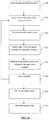
- FIG. 1is a surgical procedure setup depicting the components of a surgical planning, assessment, and correction system, according to one embodiment
- FIG. 2is a perspective view of one embodiment of a digitizer array in the closed position comprising part of the system of FIG. 1 ;
- FIG. 3is an exploded perspective view of the digitizer array of FIG. 2 ;
- FIG. 4is a perspective view of the digitizer array of FIG. 2 in the open position
- FIG. 5is a front view of one embodiment of a digitizer pointer assembly comprising part of the system of FIG. 1 ;
- FIG. 6is a perspective view of various surgical pointers compatible with the digitizer array of FIG. 2 ;
- FIG. 7is a partial perspective view of the offset pointer of FIG. 6 in a collapsed position
- FIG. 8is a partial exploded view of the offset pointer of FIG. 6 ;
- FIG. 9is a partial perspective view of the offset pointer of FIG. 6 in an extended position
- FIG. 10is a flowchart depicting the steps of the spatial tracking algorithm according to one embodiment
- FIG. 11is a flowchart depicting the rod bending workflow according to one embodiment
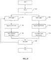
- FIG. 12is a flowchart depicting the steps in generating a rod solution according to a first embodiment
- FIG. 13is a flowchart depicting the steps in generating rod solution according to a second embodiment
- FIG. 14is a flowchart depicting the steps in generating a rod solution according to a third embodiment
- FIG. 15is a flowchart depicting the steps of the rod bending process according to a first embodiment
- FIG. 16is a screen shot depicting an example setup screen of the system of FIG. 1 ;
- FIG. 17is a screen shot depicting an example IR positioning sensor setup screen of the system of FIG. 1 ;
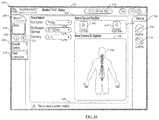
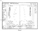
- FIG. 18is a screen shot depicting an example screw location digitization screen during a first step in the Acquire Screws step of FIG. 15 ;
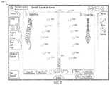
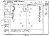
- FIG. 19is a screen shot depicting an example screw location digitization screen during a second step in the Acquire Screws step of FIG. 15 ;
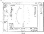
- FIG. 20is a screen shot depicting an example screw digitization screen during a third step in the Acquire Screws step of FIG. 15 ;
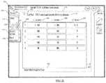
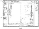
- FIG. 21is a screen shot depicting an example bend instructions screen in the Bend Instructions step of FIG. 15 ;
- FIG. 22is a flowchart depicting the steps of the rod bending process according to a second embodiment
- FIG. 23is a screen shot depicting an example Advanced Options menu screen of the system of FIG. 1 ;
- FIG. 24is a screen shot illustrating a first example screen of an Adjust Points feature according to one embodiment
- FIG. 25is a screen shot illustrating a second example screen of the Adjust Points feature of FIG. 24 ;
- FIG. 26is a screen shot illustrating a third example screen of the Adjust Points feature of FIG. 24 ;
- FIG. 27is a screen shot illustrating a first example screen of a Pre-Bent Preview feature according to one embodiment
- FIG. 28is a screen shot illustrating a second example screen of the Pre-Bent Preview feature of FIG. 27 ;
- FIG. 29is a screen shot illustrating a third example screen of the Pre-Bent Preview feature of FIG. 27 ;
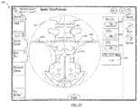
- FIG. 30is a screen shot illustrating a first example screen of a Sagittal Correction feature according to one embodiment
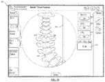
- FIG. 31is a screen shot illustrating a second example screen of the Sagittal Correction feature according to the first embodiment
- FIG. 32is a screen shot illustrating a first example screen of the Sagittal Correction feature according to a second embodiment
- FIG. 33is a screen shot illustrating an additional example screen of the Sagittal Correction feature according to the first and/or second embodiment
- FIG. 34is a screen shot illustrating a first example screen of the Coronal Correction feature according to a first embodiment
- FIG. 35is a screen shot illustrating a second example screen of the Coronal Correction feature according to the first embodiment
- FIG. 36is a screen shot illustrating a first example screen of the Coronal Correction feature according to a second embodiment
- FIG. 37is a screen shot illustrating a second example screen of the Coronal Correction feature according to the second embodiment.
- FIG. 38is a screen shot illustrating a first example screen of the Coronal Correction feature according to a third embodiment
- FIG. 39is a screen shot illustrating a second example screen of the Coronal Correction feature according to the third embodiment.
- FIG. 40is a screen shot illustrating a third example screen of the Coronal Correction feature according to the third embodiment.
- FIG. 41is a screen shot illustrating a fourth example screen of the Coronal Correction feature according to the third embodiment.
- FIG. 42is a screen shot illustrating a first example screen of the Coronal Correction feature according to a second embodiment
- FIG. 43is a screen shot illustrating a second example screen of the Coronal Correction feature according to the second embodiment.
- FIG. 44is a screen shot illustrating a third example screen of the Coronal Correction feature according to the second embodiment.
- FIG. 45is a screen shot illustrating a first example screen of the Coronal Correction feature according to the third embodiment.
- FIG. 46is a screen shot illustrating a second example screen of the Coronal Correction feature according to the third embodiment.
- FIG. 47is a screen shot illustrating a third example screen of the Coronal Correction feature according to the third embodiment.
- FIG. 48is a screen shot illustrating a fourth example screen of the Coronal Correction feature according to the third embodiment.
- FIG. 50is a flowchart illustrating the steps of the Global Spinal Balance feature according to one embodiment
- FIG. 51is a screen shot illustrating a first example screen of the Global Spinal Balance feature in pre-operative mode
- FIG. 52is a screen shot illustrating a first example screen of the Global Spinal Balance feature in target mode
- FIG. 53is a screen shot illustrating a second example screen of the Global Spinal Balance feature in target mode
- FIG. 54is a screen shot illustrating a first example screen of the Global Spinal Balance feature in intraoperative mode
- FIG. 55is a screen shot illustrating a second example screen of the Global Spinal Balance feature in intraoperative mode
- FIG. 56is a screen shot illustrating a third example screen of the Global Spinal Balance feature in intraoperative mode
- FIG. 57is a screen shot illustrating a fourth example screen of the Global Spinal Balance feature in intraoperative mode
- FIG. 58is a screen shot illustrating a fifth example screen of the Global Spinal Balance feature in intraoperative mode
- FIG. 59is a screen shot illustrating a first example screen of a Coronal Assessment and Correction feature according to a first embodiment
- FIG. 60is a screen shot illustrating a second example screen of a Coronal Assessment and Correction feature according to the embodiment of FIG. 60 ;
- FIG. 61is a screen shot illustrating a third example screen of a Coronal Assessment and Correction feature according the embodiment of FIG. 60 ;
- FIG. 62is a screen shot illustrating a fourth example screen of a Coronal Assessment and Correction feature according to the embodiment of FIG. 60 ;
- FIG. 63is a perspective view of one embodiment of a mechanical rod bender comprising part of the system of FIG. 1 ;
- FIG. 64is a screen shot illustrating a first example screen of a spinal parameter assessment feature in intraoperative mode
- FIG. 65is a screen shot illustrating a second example screen of a spinal parameter assessment feature in intraoperative mode
- FIG. 66is a screen shot illustrating a third example screen of a spinal parameter assessment feature in intraoperative mode
- FIG. 67is a screen shot illustrating a fourth example screen of a spinal parameter assessment feature in intraoperative mode
- FIG. 68is a screen shot illustrating a fifth example screen of a spinal parameter assessment feature in intraoperative mode
- FIG. 69is a screen shot illustrating a sixth example screen of a spinal parameter assessment feature in intraoperative mode
- FIG. 70is a screen shot illustrating a seventh example screen of a spinal parameter assessment feature in intraoperative mode.
- FIG. 71is a screen shot illustrating an eighth example screen of a spinal parameter assessment feature in intraoperative mode.
- a surgical planning, assessment, and correction system 10including a spatial tracking system 12 to obtain the location of one or more surgical implants 14 , a control unit 16 containing software to convert the implant locations to a series of bend instructions, and a bending device 18 to execute the bend instructions.
- the spatial tracking system 12includes an IR position sensor 20 , a digitizer pointer 23 , as well as other components including Host USB converter 21 .
- the spatial tracking system 12is in communication with control unit 16 .
- the control unit 16has spatial relation software and C-arm video import capabilities and is communicatively linked to the display 32 so that information relevant to the surgical procedure may be conveyed to the user in a meaningful manner.
- the relevant informationincludes, but is not limited to, spatial positioning data (e.g., translational data in the x, y, and z axes and orientation/rotational data R x , R y , and R z ) acquired by the IR position sensor 20 and intraoperative fluoroscopic images generated by the C-arm fluoroscope.
- spatial positioning datae.g., translational data in the x, y, and z axes and orientation/rotational data R x , R y , and R z
- the system 10comprises a neuromonitoring system communicatively linked to the spatial tracking system 12 and/or the C-arm via the control unit 16 .
- the neuromonitoring systemmay be the neuromonitoring system shown and described in U.S. Pat. No. 8,255,045, entitled “Neurophysiologic Monitoring System” and filed on Apr. 3, 2008, the entire contents of which are hereby incorporated by reference as if set forth fully herein.
- FIGS. 2-9depict the various components of one or more digitizer pointers 23 for use with the present invention.
- FIGS. 2-4detail an example IR-reflective tracking array 22 component of the digitizer pointer 23 .
- Array 22includes a housing 34 , bilateral shutters 36 , and a plurality of IR-reflective spheres 38 arranged in a calculated manner at various locations on the array 22 such that their position information is selectively detectable by the IR position sensor 20 .
- Housing 34comprises a top housing 40 , bottom housing 42 , and a distal threaded aperture 56 configured to threadably receive the threaded end 78 of a stylus (e.g., stylus 24 , 26 , 28 , and/or 30 ).
- a styluse.g., stylus 24 , 26 , 28 , and/or 30 .
- Top housing portion 40is further comprised of upper portion 44 , underside 46 , and sides 48 .
- a plurality of sphere apertures 52extend between upper portion 44 and underside 46 and are sized and dimensioned to receive reflective spheres 38 within recessed pockets 54 .
- Each side 48includes cutout 50 sized and dimensioned to receive tongue 70 .
- Bottom housing 42is comprised of a first face 58 and a second face 60 .
- the first face 58includes nesting platforms 62 and bullet posts 64 .
- Each shutter 36includes handle portion 66 , cover portion 68 , tongue 70 , interdigitating gear teeth 72 , and channel 74 for receiving bullet posts 64 .
- a spring 76extends between the two shutters 36 and is held in place via spring posts 71 .
- each IR-reflective sphere 38is nested on a platform 62 .
- Top housing 40is placed over bottom housing 42 in a snap fit configuration such that each IR-reflective sphere 38 fits within a recessed pocket 54 within its respective sphere aperture 52 .
- bilateral shutters 36are positioned over the housing 34 with tongues 70 sliding into cutouts 50 such that each shutter cover 68 obscures exactly one half of the IR-reflective sphere 38 (for example, the middle IR-reflective sphere 38 ) as depicted in FIG. 2 .
- the IR-reflective tracking array 22mates with one or more surgical objects (for example styluses 24 , 26 , 28 , 30 ).
- Each stylus 24 , 26 , 28 , 30includes a threaded proximal end 78 for mating with the threaded distal aperture 56 of the IR-reflective tracking array 22 , elongate shaft 80 , and shaped distal tip 82 .
- Shaped distal tip 82may be any shape that is complimentary to, and fits securely within, the shape of a particular screw head. For example, FIG.
- FIG. 6shows styluses 24 , 26 , 28 , and each with a different shaped distal tip designed to mate with different open screw systems, minimally-invasive screw systems, and closed tulip, iliac, and offset connector systems.
- the distal tip 82is preferably inserted into each screw while orienting the digitizer pointer coaxial to that screw (or other fixation device).
- the length of the elongate shaft 80is fixed relative to the array 22 such that all digitized points are a consistent length from the geometry of the IR-reflective markers 38 and position information may be obtained from this relationship.
- the length of the elongate shaft 80is adjustable relative to the array 22 such as that shown with stylus 30 , effectively elongating the distance from the digitized point and the IR-reflective markers. This longer distance translates to digitization of a point above the actual screw head based on the distance the user adjusted the elongate shaft 80 .
- the resulting bend instructionswould shape a rod that traverses that point above the screw allowing the user to reduce the screw to the rod.
- offset pointer 30includes an elongate tubular member 84 and an inner piston 86 .
- Elongate tubular member 84is comprised of a milled helical slot 104 and a plurality of offset depth slots 106 located around the helix that correspond to a plurality of offset distances as will be described below.
- Inner piston 86includes shaft 88 , T-shaped cap 92 , springs 94 , and bushing 96 .
- the T-shaped cap 92is positioned over the proximal end of the shaft 88 and is preferably welded to the proximal end 105 of the elongate tubular member 84 .
- Springs 94are slideably positioned along the length of the shaft 88 between the distal end 93 of the T-shaped cap 92 and bushing 96 .
- Bushing 96is positioned over the distal end of the shaft 88 .
- Pin 100is travels through, and protrudes laterally from, slots 90 , 98 on the inner shaft 88 and bushing 96 , thereby securing the bushing 96 to the inner shaft 88 .
- the pin 100is sized and dimensioned such that it travels through the helical slot 104 and be positioned within each of the offset depth slots 106 .
- the offset pointer 30gives the user the ability to execute planned screw movement by a specific, pre-determined amount.
- the userinserts the offset pointer 30 into the screw head. Keeping the distal tip 82 engaged to the screw head, the user then selects an offset amount to be added to the screw and angles the offset pointer 30 in the direction he or she wishes to apply the offset to.
- the shaft 88is pulled away from the array 22 and twisted until the pin 100 falls into the desired offset slot 106 . As the shaft 88 is pulled, it telescopes in and out of the elongate tubular member 84 such that the distance between the shaped distal end 82 and the array 22 is increased. For purposes of illustration, FIG.
- Offset options for sagittal correctionmay be provided, by way of example only from 0 mm to 16 mm offsets in 2 mm increments.
- the system 10will then acquire position information at that point in space as opposed to where the screw sits, allowing for sagittal correction of one or more vertebral levels.
- the digitizer pointer 23may be used to acquire positional information about some or all screw locations.
- the shaped distal tip 82is coaxially aligned into the screw head and the array 22 is triggered to register the screw point.
- Screw locationsmay be digitized in a superior-inferior or inferior-superior direction.
- the first screw location digitizedcorrelates to the rod insertion direction component of the bend instructions (described below).
- Squeezing handles 66activates the spring mechanism and permits the shutters 36 to open equally via the interdigitating gear teeth 72 ( FIG. 4 ).
- Opening the shutter covers 68exposes the middle IR-reflective sphere 38 and allows the IR tracking array 22 to be “seen” by the IR position sensor 20 and the position of the digitizer pointer 23 to be digitized. In this way, the IR position sensor 20 only recognizes the digitizer pointer 23 once the middle sphere 38 is exposed which allows for point-by-point tracking and obviates the sensing and digitization of one or more unnecessary data points which may occur with prior art systems that continually track surgical objects. Further, use of the gear mechanism allows the passive IR-reflective sphere 38 to be “seen” symmetrically by the IR position sensor 20 , thereby enabling a more accurate calculation of position information by the system 10 .
- control unit 16emits an audible sound to notify the user that the middle sphere 38 is recognized by the IR position sensor 20 and the screw point is acquired. Once a point has been registered, the shutter handles 66 may be released, thereby closing the bilateral shutters 36 . This process is then repeated for all screw locations to be digitized.
- the surgical bending algorithmsmay be divided into two smaller sub-systems: (1) the spatial location algorithms that acquire, collect, and digitize points in space and (2) the bending algorithms that analyze the points and calculate the bend instructions and rod length needed to bend a rod with the mechanical bending device 18 .
- the spatial tracking system 12measures the six degrees of freedom (6 DOF) information for the tracked IR-reflective spheres 38 . These data provide the full pose (position and orientation) of each screw of interest which may then be made available to the algorithm library to calculate the bend instructions.
- FIG. 10is a flow chart indicating the steps of the spatial location data acquisition process according to one embodiment.
- the system 10initializes the sensor objects from configuration to connect to, control, and read data from the IR position sensor 20 (step 140 ).
- the system 10inspects all devices connected to it and finds the device with a device ID that corresponds to the IR position sensor 20 (step 141 ).
- step 142if an IR position sensor 20 is found at step 141 , the system 10 continues to establish a connection with the IR position sensor 20 (step 143 ). However, if not, the system 10 continues to search. After the system 10 connects to the IR sensor 20 , it then loads a tool file that defines the array 22 (step 144 ). After initialization and tool file loading, the IR sensor 20 must prepare for taking data. At step 145 , the IR sensor 20 is enabled and ready to generate positional data but is left idle until tracking is enabled. By way of example and as described with reference to FIG. 17 , selecting the position of the IR sensor 20 with respect to the patient's body causes the control unit 16 to send the IR sensor 20 a command to begin tracking.
- the IR sensor 20may be polled to for data (step 147 ).
- new datais requested twenty times per second from the IR sensor 20 .
- the data generated from polling the IR sensor 20is checked to ensure that it is reporting valid data. The data may be considered valid if all of the IR-reflective spheres 38 are visible to the IR sensor 20 , the digitizer pointer 23 is fully inside the IR sensor's 20 working volume, there is no interference between the IR sensor 20 and the digitizer pointer 23 , and both the location and rotation information reported are not null.
- step 149if the data is not deemed valid, then the digitized point is not used by the system 10 and polling is resumed. If the fifth IR-reflective sphere 38 (i.e. the middle sphere) is visible on the digitizer pointer 23 (step 150 ), the process of collecting positional data for the bend algorithm commences. If the middle sphere 38 is not visible, then the data is available to the system 10 only to show proximity of the IR sensor 20 and IR-reflective tracking array 22 (step 151 ). Points used by the bend algorithm are preferably an average of several raw elements (step 152 ). Normally, five points are collected at this step before the points are processed and made available to the bend algorithm. The position data is averaged using a mean calculation.
- the directionsare averaged in the quaternion representation (raw form) then converted to a unit direction vector.
- the datais rotated from the spatial tracking system 12 coordinate from into the system 10 coordinate frame using a rotation matrix.
- the datais available for the bend algorithm to collect and process further as will be described in greater detail below.
- the surgical bending softwaretakes the location and direction data of the screw locations as described above and uses one or more geometry-based algorithms to convert these relative screw locations into a series of bend instructions.
- FIG. 11is a flow chart indicating the steps of the surgical bending process according to a first embodiment.
- the system 10may validate the system inputs to ensure the rod overhang is greater than zero, validate the sensor setup to ensure that the IR sensor 20 location has been set, and validate each of the acquired points.
- the validation of each of the acquired pointsensures, for example, that there are at least two screw points digitized, no two screw locations are too far apart, no two screw locations are too close together, and the span between the superior-most and inferior-most screw locations is not longer than the longest available rod.
- the datamay be centered and aligned such that the first data point acquired is set at the system 10 coordinate's origin and all data is aligned to the x-axis of the system's coordinates thereby reducing any potential misalignment of the IR sensor 20 relative to the patient's spine.
- the system 10may perform rod calculations for a straight rod solution, a pre-bent rod solution, and a custom-bend solution.
- a straight rod solutionthe system 10 first determines the length of a straight rod that will span all of the screw locations. This length may be calculated to accommodate each of the screw heads, hex and nose lengths of the rods chosen, and the user's selected rod overhang length.
- the system 10fits the data to a straight line, if the screw data is within tolerance of the straight line, then the bend instructions will return a straight rod, otherwise it will return no rod solution and proceed to look for a pre-bent rod solution.
- the tolerancemay be 2 mm in each of the sagittal and coronal planes.
- the system 10For a pre-bent rod solution, the system 10 first determines the length of the shortest pre-bent rod from the available rod from the available rods (as will be described in greater detail below) that will span all of the screw locations. This length may be calculated to accommodate each of the screw heads, hex and nose lengths of the rods chosen, and the user's selected rod overhang length. Next, the system 10 fits the digitized screw data to a circular arc in 3-dimensional space. If the screw data is within the tolerance of the arc, then the bend instructions will return a pre-bent rod solution, otherwise it will return no rod solution and proceed to look for a custom-bend rod solution. By way of example, this tolerance may be 2 mm in each of the sagittal and coronal planes.
- FIG. 12depicts a flow chart of a custom bend algorithm according to one embodiment.
- screw location and direction datais generated by the spatial tracking system 12 as set forth above. The data is then projected into two planes: the x-y plane (coronal view) and the x-z plane (sagittal view). Each projection is then handled as a 2D data set.
- a fixed size loopis generated over small incremental offsets for the first bend location for the end of the rod which optimizes the ability of the bend reduction step 162 to make smooth solutions.
- the system 10creates a spline node at each screw location and makes a piecewise continuous 4 th order polynomial curve (cubic spline) through the screw points.
- the smooth, continuous splineis sampled at a regular interval (e.g., every 1 cm) along the curve to generate an initial set of proposed bend locations.
- a regular intervale.g., every 1 cm
- as many bends as possibleare removed from the initial set of proposed bend locations from step 161 as possible to reduce the number of bends the user must execute on a rod in order to fit it into a screw at each digitized screw point.
- no bendis removed if eliminating it would: (1) cause the path of the bent rod to deviate more than a predefined tolerance limit; (2) cause any of the bend angles to exceed the maximum desired bend angle; and (3) cause the rod-to-screw intersection angle to exceed the maximum angulation of the screw head.
- the 2D data setsare combined and handled as a 3D data set.
- the 3D line segmentsare then evaluated based on distance between each line segment interaction (Location), the angle between two line segments (Bend Angle), and the rotation (Rotation) needed to orient the bend into the next bend plane using the following calculations: (( X 2 ⁇ X 1 ) 2 +( Y 2 ⁇ Y 1 ) 2 +( Z 2 ⁇ Z 1 ) 2 ) 1/2
- the loopis completed (step 163 ).
- the system 10may output the rod solution having the smallest maximum bend angle (i.e., the smoothest bent rod). It is to be appreciated that the system 10 may choose the rod solution displayed based on any number of other criteria.
- the system 10then generates the three-dimensional locations of the bends in space.
- the system 10generates instructions for the user to choose a straight rod, a pre-bent rod, or to custom bend a rod (step 157 ). All of the output instructions are human-readable strings or characters. In all cases, the length of the required rod is calculated as described above and is displayed to the user as either a cut rod or standard rod. For custom bend solutions, rods are loaded into the bender with the “inserter end” (e.g., one pre-determined end of the rod) into the bender collet 126 .
- the instructionsare flipped, and the cut (or nose) end of the rod is instructed to be put into the bender collet 126 .
- the bend instructionsare generated from the geometric bend locations and are given as “Location”, “Rotation”, and “Bend” values as will be described in greater detail below. These values correspond to marks on the mechanical bender 18 .
- FIGS. 13-14depict a flow chart of a second embodiment of a custom bend algorithm.
- the custom bend algorithmincludes a virtual bender used to render a virtual rod. The following calculations and the flowcharts of FIGS. 13-14 highlight the steps of this embodiment.
- a virtual bender (B)consists of a mandrel (M) of radius M r (mm).
- Mmandrel
- M rradius
- the key assumption when bending the virtual rod around Mis the conservation of arc length.
- the virtual rod, Ris bent according to a list of instructions.
- Each instructionconsists of a location (I l ), rotation (I r ), and bend angle (I ⁇ ).
- the locationis the position of the rod in the bender and corresponds to the point directly under the mandrel M.
- the rotationis given in degrees (0°-360°) and corresponds to the amount the rod is rotated from 0 in the collet.
- the bend angleis given by a single letter that corresponds to a specific angle in degrees. There is a corresponding notch on the bender with the same letter for the user to select.
- i0 N s ⁇ 1 which effectively orients the virtual rod to be at zero rotation in the virtual bender.
- the system 10rotates the virtual rod around the x-axis by I r (step 168 ).
- the system 10finds the point r i that matches I l .
- the virtual rodis translated by ⁇ circumflex over (r) ⁇ i .
- each rod point from i to i+M r *I ⁇is projected onto the mandrel M while preserving segment length (step 169 - 170 ).
- the virtual rodis then rotated around the x-axis by angle ⁇ I r .
- the next stepis to align the bent virtual rod to the acquired screw positions (step 172 ).
- the alignment processhas two stages-first, the system 100 finds the optimum rotation coarse scale (step 174 ). Second, the system performs the iterative closest point iteration algorithm fine scale.
- the systemfirst initializes the result close to a global minimum (step 173 ).
- this initializationfollows the approach described below.
- step 175the proposed solution may not be the global minimum. Thus, the following are repeated until convergence (step 175 ):
- Verify the erroris reduced (step 179 ).
- the virtual rodis rendered at step 180 .
- 0, then the middle point of the triad (in this case r 1 ) is redundant, provides no new information to the geometry of the rod and may be removed.
- the virtual bendermay be capable of bending a rod at any location of any angle perfectly to observe arc length.
- Using a virtually bent 3D rod to determine problem screwsi.e. screw locations with a high screw-rod fit error
- a Markov chainis a sequence of random variables, X 0 , X 1 . . . , such that the current state, the future and past states are independent.
- the system 10finds the set of bend instructions that define a rod that fits the screws in an optimum way defined by an error function. It is to be appreciated that the search of the bender space is quite complex as there are several constraints that must be observed for the algorithm to produce valid bend instructions (e.g., the bend locations cannot be in close proximity to the screws, the bend locations must be in multiples of 5 mm apart, the bend angles must be in multiples of 5°, no bend angle can be greater than 60°, etc.).
- the likelihood or error functionmay be constructed based on how well the virtual rod fits the data.
- the rodis fit to the data in the least squares sense.
- a likelihood functionis defined that incorporates, for example, a prior to prefer fewer bend instructions:
- Equation (3)there has been introduced a prior to control the number of bends introduced into the rod.
- This probabilistic approach to bend instruction generationallows for tailoring of constraints, for instance, a prior on the severity of the bends could also be introduced. Further, a prior could be introduced on how to define how close to the screws the bends may be located. This prior may have a “preferred” value, but probabilistically, there may be an optimal solution away from this idealized value.
- some hypothesized rules that may be applied to this algorithminclude, but are not limited to: birth move: add a bend to the current solution; death move; remove a bend from the current solution; update move: translate rod points along the rod. Use of this embodiment may provide more potential rod solutions to the user.
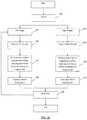
- the system 10is typically utilized at the end of a posterior or lateral fixation surgical procedure after screws, hooks or other instrumentation have been placed, but prior to rod insertion. As shown in the flowchart of FIG. 15 , the system 10 obtains position information of the implanted screw positions and outputs bend instructions for a rod shaped to custom-fit within those implanted screws. At step 190 , pertinent information is inputted into the system via a setup screen. At step 192 , the user designates the side for which a rod will be created (patient's left or right side). At step 194 , the system 10 digitizes the screw locations. At step 196 , the system 10 outputs bend instructions. At step 198 , the user bends the rod according to the bend instructions. Steps 190 - 198 may then be repeated for a rod on the contralateral side of the patient if desired.
- FIG. 16illustrates, by way of example only, one embodiment of a screen display 200 of the control unit 16 capable of receiving input from a user in addition to communicating feedback information to the user.
- a graphical user interfaceGUI
- the screen display 200may contain a header bar 202 , a navigation column 204 , device column 206 , and a message bar 208 .
- Header bar 202may allow the user to view the date and time, alter settings, adjust the system volume, and obtain help information via date and time display 210 , settings menu 212 , volume menu 214 , and help menu 216 respectively. Selecting the settings drop-down menu 212 allows the user to navigate to system, history, and shutdown buttons (not shown). For example, choosing the system button displays the rod bending software version and rod bender configuration file; choosing the shutdown option shuts down the rod bending software application as well as any other software application residing on the control unit 16 (e.g. a neuromonitoring software application); and choosing the history option allows the user to navigate to historical bend points/instruction data in previous system sessions as will be described in greater detail below.
- system buttondisplays the rod bending software version and rod bender configuration file
- choosing the shutdown optionshuts down the rod bending software application as well as any other software application residing on the control unit 16 (e.g. a neuromonitoring software application)
- choosing the history optionallows the user to navigate to historical bend points/in
- navigation column 204contains various buttons (e.g., buttons 218 , 220 , 222 , 224 , 226 ) for navigation through various steps in the rod bending process. Pressing button 204 expands/minimizes the details of the navigation column.
- Devices column 206contains various buttons indicating the status of one or more devices associated with the system 10 . By way of example, devices column 206 may include buttons 228 and 230 for the digitizer 23 and IR sensor 20 components of the system 10 , respectively. Pressing button 206 expands/minimizes the details of the devices column.
- pop-up message bar 208communicates instructions, alerts, and system errors to the user.
- FIGS. 16-17depict an example setup screen.
- the system 10Upon selecting setup button 218 on the display screen 200 , the system 10 automatically initiates the setup procedure.
- the system 10is configured to detect the connection status of each of its required components.
- icons 228 , 230indicate the connectivity and activity status of the digitizer 23 and IR sensor 20 , respectively. If one or more required components are not connected or are connected improperly, the display 200 may alert the user to address the issue before proceeding via textual, audio, and/or visual means (e.g., textual messages, audible tones, colored icons or screens, blinking icons or screens, etc.).
- the digitizer icon 228is a status indicator for the active acquisition and/or recognition of the digitizer and the presence and background color of the icon 228 may change to indicate the digitizer tracking status.
- the icon 228may be absent when the system 10 is not acquiring screws and does not recognize the digitizer, gray when the system 10 is not acquiring screws and recognizes the digitizer, green when the system 10 is in screw acquisition mode and recognizes the digitizer, and red when the system 10 is in screw acquisition mode and does not recognize the digitizer. Pressing button 206 expands/minimizes the details of the device column 206 .
- pressing icon 228expands a pull-out window for the different stylus options available with the system 10 (e.g., styluses 22 , 24 , 26 , 30 as described above).
- the IR sensor graphic icon 230is a status indicator for the IR sensor 20 . The presence and background color of the icon 230 may change to indicate the status of the IR sensor 20 .
- the icon 230may be absent when the system 10 does not recognize the IR sensor 20 , gray when the system 10 recognizes the IR sensor 20 is connected to the system 10 , and red when the system 10 senses a communication or bump error for the IR sensor 20 .
- the IR sensor 20should be recognized if it is connected after initialization of the bending application.
- the usermay then input one or more pieces of case-specific information from one or more drop-down menus.
- drop-down menus for rod system 234 , rod material/diameter 236 , rod overhang 238 , procedure type (not shown), and anatomical spinal levels of the surgical proceduremay be accessed from the setup selection panel 232 of the screen display 200 .
- the rod system drop-down menu 234allows the user to choose the rod system he/she plans to use. This selection drives choices for the rod material/diameter 236 drop-down menus.
- the system 10may be programmed with numerous fixation options from one or more manufacturers.
- the fixation system selections for one manufacturer onlye.g. NuVasive® Precept®, Armada®, and SpherX® EXT.
- the usermay also choose the combination of rod material (e.g. titanium, cobalt chrome, etc.) and rod diameter (e.g. 6.5 mm diameter, 5.5 mm diameter, 3.5 mm diameter, etc.).
- the drop-down menu 238 for material and diameter optionsmay preferably be dependent upon the choice of rod system. Because the geometry and sizes can vary between manufacturers and/or rod systems, programming the system 10 with these specific inputs can aid in outputting even more accurate bend instructions.
- the usermay also choose the amount of overhang from the rod overhang pull-down menu 238 .
- the amount of overhangmay be selectable in 0 mm, 2.5 mm, 5 mm, 7.5 mm, and 10 mm lengths.
- this functionprescribes a symmetric overhang on both the superior and inferior ends of the rod.
- this functionalso prescribes different overhang lengths on either end of the rod based on user preference and patient anatomical considerations.
- the system 10also contains functionality for accommodating multiple rod diameters and transitional rods as used, for example in Occipital-Cervical-Thoracic (OCT) fusion procedures.
- OCTOccipital-Cervical-Thoracic
- the system 10aids the user in setting up the IR sensor 20 in an optimal position for positional data acquisition.
- any visual (textual, graphic) indicatormay be used to indicate the IR sensor placement instructions.
- an active graphicdirects the user to position the IR sensor 20 relative to the digitizer array 22 held static within the patient's body. As shown in FIG. 17 , the user first selects the side of the patient the IR sensor 20 is located on by selecting the left side sensor position button 242 or right side sensor position button 244 in the IR sensor setup panel 240 .
- Choosing the left or right side sensor position button 242 , 244activates a the IR sensor positioning panel 246 such that sensor graphic 248 and a tracking volume box graphic 250 appear on the display screen 200 .
- Tracking volume box 252that moves with the sensor graphic 248 as the IR sensor 20 is moved.
- the userpositions the digitizer array 22 into the body of the patient. Once recognized by the system 10 , a target volume box 252 (which may be displayed as white in color) is positioned over the patient graphic 254 .
- the usermoves the IR sensor 20 relative to the digitizer array 22 until the tracking volume box 250 matches up to the position of the target volume box 252 .
- the sensor graphic 248increases in size if it is moved superior to the target tracking volume and decreases in size if it is moved inferior to the target volume.
- the tracking volume box 250may be color-coded to depict the relative distance to the target volume. By way of example, the tracking volume box 250 may be depicted in red if the distance to the target volume is outside of a certain distance in one or more axes (e.g., outside ⁇ 8 cm in all 3 axes.) and green if within or equal to ⁇ 8 cm in all 3 axes.
- a graphic(e.g., a check) may appear on setup button 218 to indicate such a completion and the system 10 proceeds to step 192 in the flowchart of FIG. 15 .
- the userdesignates which side of the patient's spine to acquire digitized positional information from by selecting either the Left “L” toggle/status button 220 or Right “R” toggle/status button 222 .
- the userselects the Acquire Screws button 224 which navigates the display screen 200 to an Acquire Screws (left or right) screen shown by way of example in FIGS. 18-20 .
- the display screen 200includes a sagittal view panel 256 and a coronal view panel 258 with spine graphics 260 , 262 in each of the sagittal and coronal views, respectively.
- Spine graphic 260may flip orientation depending on which side of the spine the user is digitizing (left or right).
- spine graphic 262may highlight the side of the patient the user is digitizing (left or right). The user may digitize the location of each implanted screw using, by way of example, the digitizer pointer 23 as described above.
- each screw point 264is digitized, its relative location with respect to the other acquired screw points 264 can be viewed in both sagittal and coronal views via the sagittal view panel 256 and the coronal view panel 258 as shown in FIG. 19 .
- the last screw point digitizedmay have a different graphic 266 than the previously-acquired screw points 264 (by way of example, the last screw point acquired 266 may be a halo and the previously-acquired screw points 264 may be circles).
- the screws locationsmay be digitized from a superior-to-inferior or inferior-to-superior direction and according to some embodiments, the system 10 can detect which direction the digitization is occurring in after the acquisition of two consecutive screw point locations.
- the userwishes to delete a digitized screw point, he/she may do so by pressing the “Clear Point” button 270 . If the user wishes to delete all digitized screw points, he/she may do so by pressing the “Clear All Points” button 268 .
- the usermay press the “Calculate Rod” button 272 which initiates the curve calculation preferably using one of the algorithms discussed above.
- a rod graphic 274populates through the screw points 264 , 266 and a confirmation graphic (e.g., a check) may appear on the “Acquire Screws” button 224 to indicate that the system 10 has generated a rod solution.
- the “Calculate Rod” button 272becomes the “Undo Rod” button 272 . If the user presses the “Undo Rod” button 272 , the rod solution 274 is cleared and the user may acquire more screw points or clear one or more screw points.
- the system 10may include a visual graphic for where along a rod the curve calculation is generating a severe bend (acute angle).
- the usermay select “Undo Rod” button 272 , perform one or more surgical maneuvers (e.g. reduce the screw, backup the screw, adjust the screw head, etc.), re-digitize the screw point, and generate a more feasible solution. If the rod solution is acceptable to the user, the Screw Acquisition step 194 is complete and the system 10 proceeds the Bend Instructions step 196 in the flowchart of FIG. 15 .
- the system 10may display the offending point resulting in the severe bend angle in red and offer the next-best solution that includes a bend angle falling within a pre-determined range of angles for that bender. If the rod solution is acceptable to the user, the Screw Acquisition step 194 is complete and the system 10 proceeds the Bend Instructions step 196 in the flowchart of FIG. 15 .
- the bend instructions within the bend instructions panel 276allows the user to view the bend instructions corresponding to the resulting rod solution in the Acquire Screws screen ( FIG. 20 ).
- the bend instructions panel 276contains three fields containing various aspects of the bending instruction: upper message field 278 , bender instructions field 280 , and lower message field 282 .
- the upper message field 278may communicate the rod cut length, rod type, and/or rod loading instructions to the user (e.g. “Cut Rod: 175.00 mm Load Inserter End Into Bender”).
- the bender instructions field 280displays rows 284 of bend maneuvers in location 286 , rotation 288 , and bend angle 290 to perform on the mechanical bender 18 as will be described in greater detail below. In the example shown in FIG. 21 , there are five rows indicating five bend instructions.
- the lower message field 282may communicate the direction of insertion or orientation of implanting the rod to the user. For example, the lower message field 282 shown in FIG. 21 provides the following sample instruction: “Insert Rod head to foot.” In some implementations, the rod insertion direction into the patient is dependent on the sequence of screw digitization (superior-to-inferior or inferior-to superior).
- the bend instruction algorithmtakes into account the orientation of the inferior, superior, anterior, and posterior aspects of the rod and ensures that these aspects are known to the user.
- the system 10manages which bends are imparted on the rod first based on the severity of the bend angles. The section of the bend instructions with greater bend angles may be performed first then the straighter bend sections of the bend instructions may be performed last. Further, the instructions may also direct the user to align a laser line or orientation line on the rod to an alignment arrow (not shown) on the mechanical rod bender 18 . This alignment controls the Anterior/Posterior orientation of the rod geometry and generates bend instructions accordingly.
- the userfollows the bend instructions generated by the system 10 for location (location may be color-coded on the bender 18 and on the screen 200 as green triangle), rotation (rotation may be color-coded on the bender 18 and on the screen 200 as red circle), and bend angle (bend angle may be color-coded on the bender 18 and on the screen 200 as blue square), sequentially, starting at the first bend instruction and working sequentially until the final bend is completed. From here, the user may repeat steps 190 - 198 on the rod construct for the contralateral side of the patient's spine.
- a usermay wish to toggle between left and right screens to view left and right digitized screw points, rod previews, and bend instructions for reference or comparison. Selecting the Left “L” toggle/status button 220 and right “R” toggle/status button 222 allows the user to do so.
- the GUImay additionally include a History feature. Selecting the History button (not shown) will allow the user to refer back to any previous rod bending solution.
- the usernavigates to the Bend Instructions screen 226 based on choice of the L/R toggle buttons 220 , 222 and pressing Bend Instruction button 226 . If navigating to previous bend instructions, the Bend Instructions screen will display previous bend instructions. Once the user has selected the desired rod solution, the user then executes the bends using the mechanical bender 18 .
- the system 10obtains position information of the implanted screws (steps 192 and 194 ), accepts correction inputs via one or more advanced options features (step 195 ), and generates for viewing bend instructions for a rod shaped to fit at locations apart from those implanted screw positions (step 196 ) as depicted in the flowchart of FIG. 22 . Installing a rod shaped in this manner could correct a curvature or deformity in the patient's spine according to a user's prescribed surgical plan. Details of the system 10 are discussed now discussed with examples for obtaining a rod bent according to one or more surgical plans.
- selecting the “Advanced Options” button 292expands an Advanced Options menu 292 from which the user may perform one or more corrections to the digitized screw points and the system 10 generates bend instructions that will achieve those desired corrections on the patient's spine once the rod is implanted and the screws are brought to the rod.
- a usermay wish that the rod bend solution will consider a point that is not a digitized screw point in determining the bend instructions. According to some implementations, this point is an adjusted distance from the digitized screw point location. Selecting the “Adjust Points” button 296 from the Advanced Options menu 292 navigates the user to an Adjust Points screen as depicted in FIG. 23 . Selecting a digitized screw location of interest (for example the screw point represented as dot 304 in FIG. 24 ) highlights the screw point and brings up an adjust points control 306 in each of the sagittal and coronal views 256 , 258 .
- dot 304changes color based on the distance from the originally digitized screw location as shown in FIG. 25 .
- that colorcorresponds to color-coded offset distance indicator 322 which provides visual feedback to the user as to the distance the point has been adjusted.
- dot 304appears yellow in FIG. 25 indicating that the point has moved 4 mm in each of the sagittal and coronal planes.
- the system 10may have a maximum distance from the digitized point past which it will not allow the manipulated point to exceed (by way of example only, this distance may be 5 mm). In other implementations, this distance may be depicted as a distance (for example, the numeral 18 in FIG. 48 , indicating that a screw point is 18 mm from its original location).
- the usermay adjust as many points as desired in this fashion. The user may reset all adjusted points to their original configurations via “Reset” button 316 or may undo the last adjusted point via the “Undo Last” button 318 . Once satisfied with the adjusted points, the user may either proceed to one or more additional advanced options as set forth below or select “Calculate Rod” 272 .
- the system 10generates a rod in which the curve traverses the adjusted points, as in FIG. 26 , thereby creating a correction-specific rod and providing the user with the ability to correct the curvature or deformity in the spine according to his or her prescribed curve.
- a usermay wish for a smoother rod bend.
- the “Virtual Point” button 320shown by way of example in FIG. 25
- the system 10allows the user to add an additional point anywhere in between the superior-most and inferior-most digitized screw locations. While there is no screw at this location, this point is taken into consideration during the curve calculation and may coerce the curve into a more natural shape yielding a smoother rod bend.
- the usermay either proceed to one or more additional advanced options as set forth below or select “Calculate Rod” 272 and as described above, the system 10 generates a correction-specific rod solution 274 that the user may use to correct the spine to the shape of the rod.
- pre-bent rodit may be advantageous for some patient anatomies for a user to use a pre-bent rod.
- Use of a pre-bent rodeliminates the need for making additional bends to a rod while assuring that a desirable rod curve is achieved.
- selecting the “View Pre-Bent Rod” button 298 from the Advanced Options menu 292navigates the user to a “View Pre-Bent Rod” screen as depicted in FIGS. 27-28 .
- the system 10calculates and outputs the best pre-bent rod geometry based on the selected manufacturer's rod system that was chosen during the setup step 190 (e.g.
- a color-coded offset distance indicator 322may provide the user with an indication of the distance each screw position will be from the pre-bent rod construct.
- the system 10proceeds to the Bend Instructions step 196 which displays the corresponding pre-bent rod specifications in the Bend Instructions Screen ( FIG. 29 ).
- the upper message field 278instructs the user that, based on the digitized screw points, an 85.0 mm pre-bent rod is recommended. From here, the user may decide whether the patient's anatomical and surgical requirements would be better suited with a pre-bent option or a custom-bent option. Armed with the information from FIGS. 27-29 , the user may then adjust the screw positions to fit the pre-bent rod if needed (e.g., adjust the screw head, adjust the screw depth, etc.).
- a usermay want to align or correct the patient's spine in the sagittal plane (i.e., add or subtract lordosis or kyphosis).
- the system 10includes a sagittal correction feature in which the user is able to measure the amount of lordosis in the spine and adjust angles in the sagittal plane. The system 10 then incorporates these inputs into the bend algorithm such that the rod solution includes the desired alignment or correction.
- Selecting the “View Vectors” button 300 from the Advanced Options menu 292initiates the sagittal correction feature.
- the usermay select at least two points of interest and the system then determines the appropriate vector in the sagittal view.
- the anglesare measured and adjusted based on the screw trajectory screw axis position) using the digitized screw data acquired in the Acquire Screws step 194 .
- the userselects at least two screw points of interest (e.g., screw points 338 and 342 ).
- the system 10measures the angle between the screw trajectories (shown here as 35 degrees).
- the system 10may measure the total amount of lumbar lordosis by measuring the lumbar lordosis angle 334 in the superior lumbar spine (shown in FIG. 30 as 15 degrees) and the lumbar lordosis angle 336 in the inferior lumbar spine (show in FIG. 30 as 35 degrees).
- the angle adjustment buttons 328 , 330 on the Angle Adjustment Menu 326the user may increase or decrease the desired angle correction of the spine in the sagittal plane (i.e., add or subtract lordosis or kyphosis superiorly or inferiorly). As the angle is adjusted, the angular position 336 between the two screw points 338 , 342 is changed as well.
- the system 10may include a color-coded offset distance indicator 322 to provide the user with an indication of the distance each digitized screw position will be adjusted in the sagittal plane as described above.
- the usermay select the “Set” button 332 , and then the “Calculate Rod” button 270 .
- the system 10displays a rod solution 274 incorporating the user's clinical objective for correction of the spine in the sagittal plane as depicted in FIG. 33 .
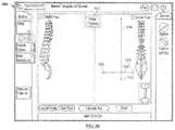
- the superior and inferior lumbar lordosis angles 354 , 356are measured, displayed, and adjusted referencing anatomy from an imported lateral radiographic image.
- lateral radiographic image 358may be inputted into the system 10 .
- the usermay touch the screen 200 and move lines 360 over at least two points of interest (e.g. the superior endplate of V 1 and the inferior endplate of V 3 ) and the system 10 then measures the angle between the two lines 360 .
- the usermay increase or decrease the desired angle correction of the spine in the sagittal plane (i.e., add or subtract lordosis or kyphosis superiorly or inferiorly).
- the amount of adjustmentis dynamically altered in its respective angle measurement box (i.e., either superior lumbar lordosis angle box 354 or inferior lumbar lordosis angle box 356 ).
- the useradjusts angle lines 360 as part of the inferior lumbar lordosis angle.
- the system 10measures this angle as 20 degrees as depicted in angle measurement field 350 .
- the userthen uses button 330 in superior angle adjustment menu 346 to increase the angle. This change is depicted in inferior lumbar lordosis angle box 356 . Once the desired amount of correction is achieved, in this example, it is achieved at 50 degrees.
- the usermay then press the capture angle button 352 and this parameter may be correlated to the digitized screw positions corresponding to the vertebral levels that those angles were measured off of.
- the system 10may include a color-coded offset distance indicator 322 to provide the user with an indication of the distance each digitized screw position will be adjusted in the sagittal plane as described above.
- the usermay select the “Set” button 332 , and then the “Calculate Rod” button 272 .
- the system 10displays a rod solution 274 incorporating the user's clinical objective for correction of the spine in the sagittal plane as depicted in FIG. 33 .
- the sagittal correction feature of the systemwill be able to account for any patient positioning-related deviations. It will also be appreciated that in addition to lordotic corrections, the sagittal angle assessment tool may be useful for other types of surgical maneuvers, including but not limited to pedicle subtraction osteotomy (PSO) procedures and anterior column reconstruction (ACR) procedures.
- PSOpedicle subtraction osteotomy
- ACRanterior column reconstruction
- a usermay want to align or correct the patient's spine in the coronal plane (i.e., correct scoliosis).
- the system 10includes one or more coronal correction features in which the user is able to view the patient's spine (and deformity) in the coronal plane via anterior-posterior x-rays; measure one or more anatomic reference angles; and/or persuade one or more screw locations towards a particular coronal alignment profile by manually or automatically biasing which direction the rod bend curve is adjusted.
- the system 10may then incorporates these inputs into the bend algorithm such that the rod solution includes the desired alignment or correction.
- Selecting the “Coronal Correction” button 302 from the Advanced Options menu 292initiates the coronal correction feature.
- the usermay wish to ascertain the degree of coronal deformity by referencing spinal anatomy, measuring the coronal Cobb angles between two anatomical references in the coronal plane, and adjusting those angles intraoperatively as part of the surgical plan to bring the spine into (or closer to) vertical alignment.
- the coronal Cobb anglesmay be ascertained using anterior-posterior radiographic images.
- Anterior-posterior radiographic image 358may be inputted into the system 10 .
- the coronal Cobb anglemay be determined by drawing lines parallel with the endplates of the most tilted vertebrae above and below the apex of the curve and measuring the angle between them. The user may touch the screen 200 and move lines 360 over at least two points of interest (e.g. the superior endplate of T 11 and the inferior endplate of L 3 ) and the system 10 then measures the angle between the two lines 360 .
- the' usermay increase or decrease the desired angle correction of the spine in the coronal plane (i.e., add or subtract correction to make the endplates of the superior and inferior vertebrae selected more parallel with one another).
- the coronal Cobb angle measurementmay be dynamically altered in the coronal Cobb angle measurement box 350 .
- the starting coronal Cobb angleis 58 degrees.
- the useruses buttons 328 , 330 to reduce the angle lines 360 between T 11 and L 3 .
- the usermay then press the capture angle button 352 .
- This parametermay be correlated to the digitized screw positions corresponding to the vertebral levels that those angles were measured off of.
- the system 10may include a color-coded offset distance indicator 322 to provide the user with an indication of the distance each digitized screw position will be adjusted in the coronal plane as described above (not shown here).
- the usermay select the “Set” button 332 , and then the “Calculate Rod” button 272 .
- the system 10displays a rod solution 274 incorporating the user's clinical objective for correction of the spine in the coronal plane.
- the coronal Cobb anglemay be displayed and adjusted referencing anatomy from digitized locations of screws placed in the left and right pedicles of the vertebrae of interest.
- the systemlinks left and right digitized screw locations for each respective vertebrae (line 361 ) and measures the angle between the two lines 361 (shown here in FIG. 36 as 58 degrees).
- the coronal Cobb anglemay be determined by selecting the screw location of the most tilted vertebrae above and below the apex of the curve. Using the angle adjustment buttons on the Angle Adjustment menu 326 , the user may increase or decrease the desired angle correction of the spine in the coronal plane (i.e.
- the Cobb angle measurementmay be dynamically altered as set forth above.
- the Cobb anglemay displayed alongside the radiographic image (shown in FIG. 36 with a starting coronal Cobb angle of 58 degrees).
- the useruses the buttons in menu 326 to reduce the angle lines 361 between T 11 and L 3 .
- the desired amount of correctionshown, by way of example, in FIG. 37 as 0 degrees, the user may then press the “Set” button 332 and this parameter may be correlated to the digitized screw positions corresponding to the vertebral levels that those angles were measured off of.
- the system 10may include a color-coded offset distance indicator 322 to provide the user with an indication of the distance each digitized screw position will be adjusted in the coronal plane as described above (not shown here). Once the desired amount of angular correction is achieved, the user may select the “Calculate Rod” button 272 . The system 10 then displays a rod solution 274 incorporating the user's clinical objective for correction of the spine in the coronal plane.
- the usermay select at least two points of interest and the system then generates a best fit reference line through all points including and lying between the at least two points of interest.
- the ideal correction of the spine in the coronal planeis a straight vertical line extending between the superior-most and inferior-most screw locations of interest.
- the usermay wish to achieve a certain amount of correction relative to the ideal correction. From the display screen, the user may select a percentage of relative correction between the screw points as digitized (0% correction) and the best fit reference line (100%).
- the systemcalculates a rod solution and shows an off-center indicator 322 to provide a user with an indication of the distance each screw is from the coronally-adjusted rod construct as set forth above.
- the usermay straighten all points within the construct (global coronal correction).
- the superior and inferior screw points 362 , 364are selected and the system 10 generates a best fit global reference line 366 through all points 362 , 364 , 368 .
- the usermanipulates the + and ⁇ buttons 372 , 374 to adjust the percentage of correction desired.
- the amount of desired correctionis shown as 100% on the percentage correction indicator 376 , meaning the rod solution 274 will be a straight line in the coronal plane and all screw locations will be adjusted to fit the rod/line.
- the percentage correction indicator 376As depicted in FIG.
- the system 10may include a color-coded offset distance indicator 322 to provide the user with an indication of the distance each digitized screw position will be adjusted in the coronal plane as set forth above. If the user deems this an acceptable rod solution, the user selects the “Calculate Rod” button 272 to view the rod solution 274 ( FIG. 41 ) and receive bend instructions or proceeds to another advanced feature as will be described in greater detail below.
- the usermay straighten a subset of the screw points within the construct (segmental coronal correction). Based on the sequence those points are inputted into the system, a best-fit segmental reference line is generated through the points in the direction of the last chosen point. If an inferior point 364 is selected first and then a superior point 362 is selected second, the system 10 will draw the best-fit segmental reference line 378 superiorly as shown in FIG. 42 . Conversely, if a superior point 362 is selected first and then an inferior point 364 is selected second, the system 10 will draw the best-fit segmental reference line 378 inferiorly.
- the usermanipulates the + and ⁇ buttons 372 , 374 to adjust the percentage of correction desired.
- the amount of desired correctionis shown as 100% on the percentage correction indicator 376 , meaning the rod solution 274 will be a straight line in the coronal plane and all selected screw locations will be adjusted to fit the rod/line.
- unselected screw locations 380will not be adjusted to fit the rod/line and their relative locations will be inputted into the system 10 and taken into consideration when the rod calculation is made. As depicted in FIG.
- the system 10may include a color-coded offset distance indicator 322 to provide the user with an indication of the distance each digitized screw position will be adjusted in the coronal plane as set forth above. If the user deems this an acceptable rod solution, the user selects the “Calculate Rod” button 272 to view the rod solution 274 ( FIG. 44 ) and receive bend instructions or proceeds to another advanced feature as will be described in greater detail below.
- segmental coronal correctionmay be achieved relative to the patient's central sacral vertical line (CSVL) instead of a best-fit segmental reference line running through two selected digitized screw locations.
- CSVLis the vertical line passing through the center of the sacrum that may serves as the vertical reference line for the patient's coronal deformity as well as a guide for spinal correction in the coronal plane in accordance with the coronal assessment and correction features of the present disclosure.
- FIGS. 45-49illustrate a method for using the CSVL line for assessing coronal deformity and achieving coronal correction according to one embodiment.
- this methodcommences after all screws are implanted into the patient and digitized in the manner set forth above.
- the usergenerates one or more radiographic images of the sacrum, localizes a superior and inferior point on the sacrum, and marks those points (e.g., implants Caspar pins, marks the patient's skin with a marker, etc.).
- the userselects the “Alignment” button 506 ( FIG. 45 ).
- the useris prompted to digitize the marked skin points representing the superior and inferior sacral landmarks. As shown by way of example in FIG.
- box 510may pop up to instruct the user of the various steps of the workflow.
- the superior point on the sacrumhas already been digitized (shown as digitized point 512 ) and check mark 514 .
- Box 510further instructs the user to “Acquire Point at Inferior End.” Selecting “Clear Coronal Alignment Line” 516 to re-digitize the sacral points and/or exit out of the CSVL coronal correction feature.
- a dashed line 518representing the patient's true CSVL line appears on the screen ( FIG. 47 ) and the digitized screw locations 264 are reoriented in system 10 relative to the CSVL line 518 .
- the display 200 in the coronal viewnow represents the patient's current coronal curve relative to a vertical reference (CSVL).
- CSVLvertical reference
- the usermay select two points (i.e., the screw segment) he/she would like to correct or straighten relative to the CSVL.
- the userselects points 542 and 544 .
- the first point chosen 542is the point of rotation of the segment and the origin of the straightening line 520 .
- the second point 544determines the direction of the straightening line 520 .
- the straightening line 520may be drawn parallel to the CSVL line 518 as the objective of coronal correction is to make the spine as vertical as possible in the coronal plane.
- the userselects the “Calculate Rod” button 272 to view the rod solution 274 ( FIG. 49 ) and receive bend instructions.
- the usernow has a rod solution he/she can pull the screws to, knowing that it is straight relative to the CSVL line and therefore providing the desired correction of the coronal deformity.
- the userwill and receive bend instructions or proceeds to another advanced feature as will be described in greater detail below.
- the system 10may include a Global Spinal Balance feature in which the control unit 16 is configured to receive and assess 1) preoperative spinal parameter measurements; 2) target spinal parameter inputs; 3) intraoperative spinal parameter inputs; and 4) postoperative spinal parameter inputs.
- One or more of these inputsmay be tracked and/or compared against other inputs to assess how the surgical correction is progressing toward a surgical plan, assess how close the patient's spine is to achieving global spinal balance, and utilized to develop/refine an operative plan to achieve the desired surgical correction.
- Spinal parametersmay comprise the patient's Pelvic Incidence (PI), Pelvic Tilt (PT), Sacral Slope (SS), Lumbar Lordosis (LL), Superior Lumbar Lordosis ( ⁇ LL), Inferior Lumbar Lordosis ( ⁇ LL), C7 Plumb Line offset (C7PL), and Thoracic Kyphosis (TK), T1 tilt, and Sagittal Vertical Axis (SVA) measurements.
- the target spinal parameter measurementsmay be a clinical guideline (by way of example only, the SRS-Schwab classification, or a patient-specific goal based on that patient's anatomy).
- these spinal parametersmay comprise Pelvic Incidence (PI), Pelvic Tilt (PT), Sacral Slope (SS), Lumbar Lordosis (LL), Superior Lumbar Lordosis ( ⁇ LL), Inferior Lumbar Lordosis ( ⁇ LL), C7 Plumb Line offset (C7PL), and Thoracic Kyphosis (TK), T1 tilt, and Sagittal Vertical Axis (SVA) measurements.
- PIPelvic Incidence
- PTPelvic Tilt
- SSSacral Slope
- ⁇ LLSuperior Lumbar Lordosis
- ⁇ LLSuperior Lumbar Lordosis
- ⁇ LLInferior Lumbar Lordosis
- C7 Plumb Line offsetC7 Plumb Line offset
- TKThoracic Kyphosis
- SVASagittal Vertical Axis
- FIG. 50depicts a flowchart indicating the steps of the Global Spinal Balance feature according to one embodiment.
- the system 10inputs a patient's preoperative spinal parameter measurements.
- the systemgenerates theoretical target spinal parameter measurements (step 392 ).
- One or more target spinal parameter measurementsmay be optionally adjusted the user in accordance with a surgical plan a step 394 .
- a target spinal rodmay be scaled to match the patient's anatomy using the theoretical or adjusted target spinal parameter measurements from step 392 or 394 . This scaled target rod may then be displayed 398 to the user.
- the system 10may generate one or more measurements (step 400 ) during the surgical procedure.
- the target spinal parameter datamay then be adjusted based on the intraoperative measurements from step 400 .
- the system 10may generate bend instructions for balanced spine correction.
- the usermay input a patient's preoperative measurements into the system 10 as depicted, by way of example in FIG. 51 .
- Selecting the Pre-Op measurement button 404allows the user to input measurements into PI, LL, Superior LL, Inferior LL, C7PL, and TK input fields 408 , 410 , 412 , 414 , 416 , 418 , and 420 respectively.
- Such pre-operative measurementsmay be obtained from manual measurement means imported from any number of commercially-available desktop and mobile software applications.
- pre-operative anatomical measurementsmay be used to understand the imbalance in the patient's deformed spine as well as help determine an operative plan to implant devices that would adjust or form the spine to a more natural balance (e.g., rods, screws, a hyperlordotic intervertebral implant, etc.).
- the global spinal balance featureallows the user to adjust the patient's anatomical measurement values to the user's preferred target spinal parameters for a balanced and/or aligned spine.
- selecting the target measurement button 406populates measurements into input fields 410 , 412 , 414 , 416 , 418 , 420 that represent an ideal or properly balanced spine. If the user accepts these target spinal parameters, the system 10 would output a theoretical rod solution comprising rod shapes and curves representing an ideal or properly balanced spine scaled and overlaid onto the digitized screw points as shown in FIG. 53 .
- the system 10may also include a color-coded offset distance indicator 322 to provide the user with an indication of the distance each digitized screw position is from the rod solution in the sagittal and coronal planes as set forth above.
- a color-coded offset distance indicator 322to provide the user with an indication of the distance each digitized screw position is from the rod solution in the sagittal and coronal planes as set forth above.
- the usermay use buttons 422 , 424 , 426 to adjust these target spinal parameters.
- the usercould then refer to the correction indicator 428 for an indication of how much correction (relative to the pre-operative and theoretical spinal parameters) would be achieved based on those adjusted input correction values.
- the user's input correction valueswould then drive the rod bending algorithm (based on the digitized screw locations) to a rod shape customized to the user's plan for that particular placement.
- the final rodcould be positioned within the patient and the screws and spine would be adjusted to the rod at the desired alignment.
- spinal parameter inputsmay be assessed intraoperatively.
- the usermay wish to intraoperatively measure the amount of lumbar lordosis that has been achieved (for example, after placement of an intervertebral implant).
- the system 10may include be configured to obtain or import one or more lateral images, generate one or more lines between two or more landmarks on the patient's anatomy, determine a relationship between those landmarks, and adjust one or more spinal parameters to be used in generating the rod solution.
- the userfirst selects the intraoperative measurement button 408 .
- lateral radiographic image 358may be inputted into the system 10 .
- the usermay touch the screen 200 and move lines 360 over at least two points of interest (e.g. the superior endplate of V 1 and the superior endplate of V 2 ) and the system 10 then measures the angle between the two lines 360 . As shown in FIG. 55 , the system 10 measures this angle as 15 degrees as indicated in the angle measurement field 350 .
- the systemmay compare the intraoperative measurement to the preoperative and/or target spinal parameter value and provide an indication to the user of how much correction has been achieved relative to the pre-operative and theoretical spinal parameters.
- the usermay increase the desired angle of correction of the spine in the sagittal plane (i.e., add or subtract lordosis or kyphosis).
- the amount of adjustmentmay dynamically displayed within angle measurement field 350 .
- the system 10may include a color-coded offset distance indicator (not shown) to provide the user with an indication of the distance each digitized screw position will be adjusted in the sagittal plane as described above.
- the usermay press the “Set” button 332 and then the “Calculate Rod” button (not shown in this view).
- the systemdisplays a rod solution 274 incorporating the user's intraoperative objective for correction of the spine in the sagittal plane.
- the usermay also wish to intraoperatively measure the patient's pelvic incidence angle.
- selecting the intra-op measurement button 408optionally brings up a PI assessment tool.
- the system 10obtains a fluoroscopic image 452 of the patient's pelvis.
- the userfirst selects the femoral head button 432 and uses arrows 450 on the PI Adjustment Menu 448 to locate the center point of the femoral head 434 .
- the userselects the posterior sacrum button 436 and uses arrows 450 to identify the posterior aspect of the sacral endplate 438 .
- the userselects the anterior sacrum button 440 and uses arrows 450 to identify the anterior aspect of the sacral end plate 442 .
- the usermay press the “Draw PI” button 446 after which the system 10 automatically draws and measures the pelvic incidence angle 446 for the user.
- the system 10may first input a patient's preoperative spinal parameter measurements. Next, the system 10 generates theoretical target spinal parameter measurements. One or more target spinal parameter measurements may then be optionally adjusted the user in accordance with a surgical plan. Next, the system 10 may measure one or more spinal parameter measurements intraoperatively and provide one or more indications to the user how the surgical procedure is progressing. Finally, the system 10 may measure one or more spinal parameter measurements postoperatively to assess the final status of the deformity correction and balance achieved.
- the usermay input a patient's preoperative measurements into the system 10 as depicted, by way of example in FIG. 51 .
- Selecting the Pre-Op measurement button 404allows the user to input measurements into PI, LL, Superior LL, Inferior LL, C7PL, and TK input fields 408 , 410 , 412 , 414 , 416 , 418 , and 420 respectively.
- Such pre-operative measurementsmay be obtained from manual measurement means imported from any number of commercially-available desktop and mobile software applications.
- pre-operative anatomical measurementsmay be used to understand the imbalance in the patient's deformed spine as well as help determine an operative plan to implant devices that would adjust or form the spine to a more natural balance (e.g., rods, screws, a hyperlordotic intervertebral implant, etc.).
- the global spinal balance featureallows the user to adjust the patient's anatomical measurement values to the user's preferred target spinal parameters for a balanced and/or aligned spine.
- selecting the target measurement button 406populates measurements into input fields 410 , 412 , 414 , 416 , 418 , 420 that represent an ideal or properly balanced spine.
- the usermay use buttons 422 , 424 , 426 to adjust these target spinal parameters.
- spinal parameter inputsmay be assessed intraoperatively.
- the usermay wish to intraoperatively measure the amount of lumbar lordosis that has been achieved (for example, after placement of an intervertebral implant).
- the system 10may be configured to obtain or import one or more lateral images, generate one or more lines between two or more landmarks on the patient's anatomy, determine a relationship between those landmarks, and adjust one or more spinal parameters to be used in generating the rod solution.
- the userfirst selects the intraoperative measurement button 408 .
- lateral radiographic image 358may be inputted into the system 10 .
- the usermay touch the screen 200 and move lines 360 over at least two points of interest (e.g.
- the system 10measures the angle between the two lines 360 . As shown in FIG. 55 , the system 10 measures this angle as 15 degrees as indicated in the angle measurement field 350 .
- the systemmay compare the intraoperative measurement to the preoperative and/or target spinal parameter value and provide an indication to the user of how much correction has been achieved relative to the pre-operative and theoretical target spinal parameters.
- the usermay increase the desired angle of correction of the spine in the sagittal plane (i.e., add or subtract lordosis or kyphosis). As the angle is adjusted, the amount of adjustment may dynamically displayed within angle measurement field 350 .
- the useris provided with a visual indication as to how the surgical procedure is proceeding relative to the targeted plan.
- a visual indicationas to how the surgical procedure is proceeding relative to the targeted plan.
- both buttonswill be represented on the screen 200 as green.
- the intraoperative lumbar lordosis measurementis greater than 10 but less than 21 degrees of the planned pelvic incidence value, then both buttons will be represented on the screen 200 as yellow.
- both buttonswill be represented on the screen 200 as red.
- the systemmay include a Coronal Offset Assessment feature configured to obtain or import one or more Anterior-Posterior images, acquire digital position information regarding landmarks on the patient's anatomy, generate one or more lines between those landmarks, and determine a relationship between those landmarks.
- the system 10first obtains a fluoroscopic image 454 of the iliac sacral region ( FIG. 57 ).
- the userdigitizes two points 456 and selects the Iliac Line: Set button 460 to establish a horizontal iliac line 458 .
- the userdigitizes the midpoint 462 of the sacrum and selects the CSVL Line: Set button 466 and the system 10 automatically generates an orthogonal line (CSVL line 464 ) from the sacral midpoint 462 to the iliac line 458 .
- the system 10then obtains a fluoroscopic image 468 of the C7 vertebra as depicted in FIG. 58 .
- the userdigitizes the midpoint 470 of the C7 vertebra and selects the “C7PL: Set” button 474 and the system 10 automatically generates an orthogonal line (C7PL line 476 ) from the midpoint 470 of C7 to the iliac line 458 .
- the system 10calculates the coronal offset distance (in box 476 ) using the offset distance between the CSVL line 464 and the C7PL line 476 line.
- the useris given an intraoperative assessment of the amount of coronal offset corrected or left to be corrected which affords the opportunity to decide if a surgical planning goal has been achieved or if one or more spinal parameter inputs need to be updated with respect to coronal alignment.
- the system 10provides the user with the functionality to select two points on the spine and generate a best-fit reference line between those two points to which to generate a rod solution and correct the spine to.
- a virtual orthogonal reference linethrough which the user may intraoperatively assess a deformed spine against and/or correct coronal a spinal deformity to.
- FIGS. 60-61describe the Virtual T-Square feature in greater detail.
- the userlocalizes three points of reference on the patient's anatomy via c-arm fluoroscopy and marks the location of those anatomical references (e.g., implants Caspar pins, marks the patient's skin with a marker, etc.).
- the anatomical points of referencemay be the left iliac crest, right iliac crest, and sacral midpoint.
- the usermay be prompted (via text box, audible alert, and the like) to digitize each of the previously-identified anatomical reference points in a manner previously described herein.
- points 528 , 530appear on the screen 200 , respectively and a horizontal line 534 representing the iliac line is drawn between the left and right iliac crest points 528 , 530 . This is shown, by way of example only as a dashed line 534 in FIG. 60 .
- the system 10registers the digitized location of the sacral midpoint, point 532 appears on screen 200 , and dashed line 536 representing the CSVL is drawn superiorly and orthogonal to the iliac line 534 .
- the system 10may use one or more algorithms to detect that, when the Virtual T-Square feature is activated, the next three acquired digitized points will correspond to the three anatomical reference points of interests.
- the CSVL line 536established the digitized screw locations 264 may be reoriented in system 10 relative to the CSVL line 536 , the user may select two points (i.e., the screw segment) he/she would like to correct or straighten relative to the CSVL as set forth above.
- the usermay also generate a rod solution, receive bend instructions, and output a rod to pull the screws to, knowing that it is straight relative to the CSVL line as explained in detail above.
- Selecting “Reset” button 316clears the lines 534 , 536 and all adjustments in the Coronal View and returns the adjusted spheres to their original digitized locations. If the user toggles off the Virtual T-square button 522 , the reference lines 526 are cleared and the orientation of the points converts back the best fit 524 within the Coronal View window.
- Coronal spinal balanceis determined by measuring the offset between the CSVL and a C7.
- the Virtual T-square featuremay be included with a C7 Plumb Line Measurement feature. After the user has acquired the CSVL line via the Virtual T-square feature 522 , the “C7 Plumb Line” button 540 is enabled. FIG. 62 describes the C7 Plumb Line feature in greater detail.
- the userlocalizes the center of the C7 vertebra via c-arm fluoroscopy and superficially marks the location of this anatomical reference on the patient's skin (e.g., with an “X”).
- the usermay be prompted (via text box, audible alert, and the like) to digitize each of the C7 vertebra points in a manner previously described herein.
- point 558appears on the screen 200 and a vertical line 538 representing the C7 Plumb Line is drawn parallel to the CSVL and orthogonal to the iliac line 534 . This is shown, by way of example only as a dashed line 538 in FIG. 62 .
- the system 10may use one or more algorithms to detect that, when the C7 Plumb Line feature is activated, the next acquired digitized points will correspond to the C7 anatomical landmark. Finally, the system 10 calculates the coronal offset distance using the offset distance between the CSVL line 536 and the C7PL line 538 .
- a double arrow lineis drawn between the two vertical lines to represent the degree of coronal offset, and hence the spinal balance or imbalance in the coronal plane (shown in FIG. 62 as 10 cm).
- a color-coded coronal offset distance indicatormay provide the user with an indication of the degree of coronal offset.
- an offset of 0-2 cmcould be indicated with a green double arrow line; an offset of 3-4 cm could be indicated with a yellow double arrow line; and an offset of greater than 4 cm could be indicated with a red double arrow line.
- the useris given an intraoperative assessment of the amount of coronal offset corrected or left to be corrected which affords the opportunity to decide if a surgical planning goal has been achieved or if one or more spinal parameter inputs need to be updated with respect to coronal alignment.
- the mechanical rod bender 18may be any bender that takes into account six degrees of freedom information as it effects bends onto a spinal rod.
- the mechanical rod bender 18may be the bender described in commonly-owned U.S. Pat. No. 7,957,831 entitled “System and Device for Designing and Forming a Surgical Implant” patented Jun. 7, 2011, the disclosure of which is hereby incorporated by reference as if set forth in its entirety herein.
- the mechanical rod bender 18may be the bender shown in FIG. 63 .
- First and second levers 106 , 110are shown as is lever handle 108 designed for grabbing the lever 106 manually and a base 112 for holding lever 110 in a static position.
- Second lever 110has a rod pass through 114 so that an infinitely long rod can be used as well as steady the rod during the bending process with the rod bending device 18 .
- the usergrabs handle 108 and opens it to bend a particular rod by picking an angle on the angle gauge 132 and closing the handle 108 such that levers 106 , 110 are brought closer together.
- the mechanical rod bender 18in other embodiments could be produced to bend the rod during the handle opening movement as well.
- the rodmoves through mandrel 118 and in between moving die 120 and fixed die 122 .
- the rodis bent between the two dies 120 , 122 . Gauges on the bender 18 allow the user to manipulate the rod in order to determine bend position, bend angle, and bend rotation.
- the rodis held in place by collet 126 .
- the rodBy sliding slide block 128 along base 112 , the rod can be moved proximally and distally within the mechanical rod bender 18 .
- Positionmay be measured by click stops 130 at regular intervals along base 112 . Each click stop 130 is a measured distance along the base 112 and thus moving a specific number of click stops 130 gives one a precise location for the location of a rod bend.
- the bend angleis measured by using angle gauge 132 .
- Angle gauge 132has ratchet teeth 116 spaced at regular intervals. Each ratchet stop represents five degrees of bend angle with the particular bend angle gauge 132 as the handle 106 is opened and closed. It is to be appreciated that each ratchet step may represent any suitable degree increment (e.g., between 0.25 degrees to 10 degrees).
- the bend rotationis controlled by collet knob 134 . By rotating collet knob 134 either clockwise or counterclockwise, the user can set a particular rotation angle.
- the collet knob 134is marked with regular interval notches 136 but this particular embodiment is continuously turnable and thus has infinite settings.
- knob 134Once a user turns knob 134 , the user can set the knob 134 at a particular marking or in between or the like to determine a particular angle rotation to a high degree of accuracy. Additionally, base 112 may have a ruler 138 along its length to aid the user in measuring a rod intraoperatively.
- the rod bender 18may be a pneumatic or motor-driven device which automatically adjusts the location, rotation and bend angle of the rod.
- three motorsmay be utilized for each movement.
- a linear translator motorwould move the rod in and out of the mandrel 118 and moving die 120 .
- One rotational motorwould rotate the rod and moving die 120 .
- the bend calculationscould be converted into an interface program that would run to power and control the motors.
- the automated benderwould lessen the possibility of user error in following the manual bend instructions. It would also increase the resolution or number of bends that can be imparted in the rod making for a smoother looking rod.
- the systems and methods hereinmeasure pelvic parameters and assess both sagittal and coronal balance intraoperatively, thereby enabling the conversion and transformation of the assessment into user actions on the patient. In some embodiments, the systems and methods herein assess the sagittal alignment interoperatively.
- One example embodimentis described below.
- FIG. 64exemplary functional features of a control unit (such as that described above) can be listed, in a sequenced workflow, in a left hand column of a GUI screen.
- exemplary functional features of a control unitsuch as that described above
- stepsare described as first, second, etc. for purposes of illustration, the present invention is not intended to be limited by such numbering of steps.
- the usercan obtain, either by intraoperative measurement or by manual user input, a first anatomical or pelvic characteristic, such as a Pelvic Incidence Angle (PI).
- PIcan be measured by selecting, for example, three points, such as the posterior and anterior points 64 - 1 , 64 - 2 of the S 1 endplate and the center of the femoral heads 64 - 3 .
- the control unit or usercan then draw geometric lines and calculate the PI angle based on the three point selection ( FIG. 64 ).
- a second stepcan include the user intraoperatively measuring a second anatomical or pelvic characteristic, such as the patient's Sacral Slope (SS) ( FIGS. 65-66 ).
- a true vertical reference line 65 - 1can be obtained or created. This can be accomplished by manual input by the user, or using a guidance reticle, or positioning two radio dense markers (not shown) at the 12 and 6 o'clock positions on the c-arm receiver face.
- a fluoroscopic imagecan be taken of the S 1 endplate ( FIGS. 65-66 ).
- the angle 65 - 3 between the S 1 endplate 65 - 2 and the vertical line 65 - 1can then be measured by the control unit or manually by the user, thus resulting in the SS angle.
- a targeted second anatomical characteristiccan be created.
- the anatomical targetcan be in the form of a factor like an industry recognized classification modifier, such as an SRS Schwab classification sagittal modifier of PT ⁇ 20 degrees.
- the targeted SS and/or actual SScan be converted or transformed to a patient position—i.e., targeted patient position and/or actual patient position.
- this conversioncan take the form of a user positioning a patient so that the actual SS (i.e., actual patient position) moves towards and/or converges on the targeted SS (i.e., targeted patient position).
- the actual and targeted SScan be in the form of graphical representations.
- the targeted SSis not achieved during patient positioning, then the patient's pelvis can be re-positioned (anteverted), as an example, in order to obtain the targeted SS (i.e., PT ⁇ 20 in this embodiment).
- the PTcan be displayed, for example, in a Red color ( FIG. 65 ) when the intraoperative angle (i.e., actual patient position) has not achieved the targeted patient position, or in a Green color ( FIG. 66 ) when the interoperative angle has achieved the targeted patient position).
- a Red colorFIG. 65
- a Green colorFIG. 66
- a third stepcan be to position the patient such that their sagittal vertical axis (SVA) is within another anatomical target or desired clinical outcome, such as +/ ⁇ 5 cm, which is another SRS Schwab classification sagittal modifier ( FIG. 67 ).
- SVAsagittal vertical axis
- Thiscan be done by using a central radio dense marker 67 - 1 placed on the c-arm receiver. Fluoroscopic images can be taken until the central marker is positioned on the posterior point of the S 1 endplate, as an example. At that point, the height of the c-arm may be noted and manually entered into the system. Then, the c-arm may be translated so that the central marker 68 - 1 can be localized at the mid-body of the C7 vertebra ( FIG. 68 ).
- the c-arm heightmay have to be adjusted to accomplish this localization. At that point, the c-arm height can be again noted and manually entered into the system. The difference is calculated which results in the SVA offset value ( FIG. 69 ). If the value is outside of the target, such as +/ ⁇ 5 cm ( FIG. 69 ), then the same can be converted or transformed to a repositioning of the patient's upper body/shoulders until the SVA is within +/ ⁇ 5 cm. The SVA value can be displayed as Red or Green based on this criteria. When the PT and SVA ( FIG. 69 ) are green ( FIG. 70 ), then the patient can be deemed properly positioned for the surgery to proceed.
- SRS sagittal modifieri.e., anatomical target or desired clinical outcome
- this featurecan measure lumbar lordosis and display the PI ⁇ LL based on that measurement and the entered PI.
- Surgerycan proceed when the PI ⁇ LL is within 9 degrees ( FIG. 71 ).
- the present inventionmay be implemented using any combination of computer programming software, firmware, or hardware.
- the computer programming code(whether software or firmware) according to the invention will typically be stored in one or more machine readable storage mediums such as fixed (hard) drives, diskettes, optical disks, magnetic tape, semiconductor memories such as ROMs, PROMs, etc., thereby making an article of manufacture in accordance with the invention.
- the article of manufacture containing the computer programming codeis used either by executing the code directly from the storage device, by copying the code from the storage device into another storage device such as a hard disk, RAM, etc. or by transmitting the code for remote execution.
Landscapes
- Health & Medical Sciences (AREA)
- Life Sciences & Earth Sciences (AREA)
- Orthopedic Medicine & Surgery (AREA)
- Surgery (AREA)
- Engineering & Computer Science (AREA)
- Public Health (AREA)
- General Health & Medical Sciences (AREA)
- Veterinary Medicine (AREA)
- Biomedical Technology (AREA)
- Heart & Thoracic Surgery (AREA)
- Medical Informatics (AREA)
- Molecular Biology (AREA)
- Animal Behavior & Ethology (AREA)
- Nuclear Medicine, Radiotherapy & Molecular Imaging (AREA)
- Neurology (AREA)
- Robotics (AREA)
- Pathology (AREA)
- Oral & Maxillofacial Surgery (AREA)
- Physics & Mathematics (AREA)
- Biophysics (AREA)
- Dentistry (AREA)
- Surgical Instruments (AREA)
Abstract
Description
((X2−X1)2+(Y2−Y1)2+(Z2−Z1)2)1/2 Location:
arc-cosine(V12⋅V23) Bend Angle:
- where ⋅ is the dot product and V is a vector between 2 points
arc-cosine(N123⋅N234) Rotation: - where ⋅ is the dot product and N is the normal vector to a plane containing 3 points.
These calculated numbers are then tabulated to the physical design of therod bender 18 and the selected rod material and diameter. Bend angles account for the mechanical rod bender's18 tolerance and will account for the rod's material and diameter based on previous calibration testing performed withmechanical rod bender 18 and the specific kind of rod. Calibration testing quantifies the amount of spring-back that is expected when bending a certain rod material and diameter. By way of illustration, a 5.5 mm diameter titanium rod's spring-back can be characterized by a 1storder linear equation:
BAA=0.94*BAT−5.66
where BATis the theoretical bend angle needed that was calculated from the 3D line segment and BAAis the actual bend angle needed to bend the rod to so it can spring back to the theoretical bend angle. Thus, using this equation, when 20 degrees of bend is calculated from the 3D line segment above, the “spring-back” equation for that rod will formulate that a 25 degree bend needs to be executed in order for it to spring-back to degrees. The length of the final rod is the total of all the calculated distances plus the selected rod overhang.
- where ⋅ is the dot product and V is a vector between 2 points
s=[s0, . . . ,sN−1]∈R3×N (1)
It may be assumed that the screws have been collected in order (e.g. superior-most screw to inferior-most screw or inferior-most screw to superior-most screw) so the index i can also be thought of as the index through time.
δi=|ri+1s−ris|. Let Δd=Σi=0αδi, then ΔN
∫dR=∫dR (2)
where T denotes the rotation matrix. Let {circumflex over (T)} denote the optimum 3D rotation matrix, then
It turns out that {circumflex over (T)}=UVT, where
(step177)
Given an ordered set of screws that define a construct
s=[s0, . . . ,sN−1]∈R3×N (2)
where si=[six, siy, siz]Tdenotes the ith3D screw digitized by the user, the
such that the log-likelihood function may be defined as
where Nbdenotes the number of bends in the rod, Nsdenotes the number of screw locations, s; is the ith screw, riis the ith rod point, and α is the control hyper-parameter for the number of bends (e.g. α=0.05).
Claims (9)
Priority Applications (4)
| Application Number | Priority Date | Filing Date | Title |
|---|---|---|---|
| US15/045,084US10695099B2 (en) | 2015-02-13 | 2016-02-16 | Systems and methods for planning, performing, and assessing spinal correction during surgery |
| US16/867,516US11376045B2 (en) | 2015-02-13 | 2020-05-05 | Systems and methods for planning, performing, and assessing spinal correction during surgery |
| US17/718,933US12167870B2 (en) | 2015-02-13 | 2022-04-12 | Systems and methods for planning, performing, and assessing spinal correction during surgery |
| US18/982,653US20250114127A1 (en) | 2015-02-13 | 2024-12-16 | Systems and methods for planning, performing, and assessing spinal correction during surgery |
Applications Claiming Priority (2)
| Application Number | Priority Date | Filing Date | Title |
|---|---|---|---|
| US201562116230P | 2015-02-13 | 2015-02-13 | |
| US15/045,084US10695099B2 (en) | 2015-02-13 | 2016-02-16 | Systems and methods for planning, performing, and assessing spinal correction during surgery |
Related Child Applications (1)
| Application Number | Title | Priority Date | Filing Date |
|---|---|---|---|
| US16/867,516DivisionUS11376045B2 (en) | 2015-02-13 | 2020-05-05 | Systems and methods for planning, performing, and assessing spinal correction during surgery |
Publications (2)
| Publication Number | Publication Date |
|---|---|
| US20160242857A1 US20160242857A1 (en) | 2016-08-25 |
| US10695099B2true US10695099B2 (en) | 2020-06-30 |
Family
ID=56693350
Family Applications (8)
| Application Number | Title | Priority Date | Filing Date |
|---|---|---|---|
| US15/045,084Active2038-03-28US10695099B2 (en) | 2015-02-13 | 2016-02-16 | Systems and methods for planning, performing, and assessing spinal correction during surgery |
| US15/044,947AbandonedUS20160262800A1 (en) | 2015-02-13 | 2016-02-16 | Systems and methods for planning, performing, and assessing spinal correction during surgery |
| US15/674,283AbandonedUS20170367738A1 (en) | 2015-02-13 | 2017-08-10 | Systems and Methods for Planning, Performing, and Assessing Spinal Correction During Surgery |
| US16/351,107AbandonedUS20190209212A1 (en) | 2015-02-13 | 2019-03-12 | Systems and methods for planning, performing, and assessing spinal correction during surgery |
| US16/867,516Active2036-02-28US11376045B2 (en) | 2015-02-13 | 2020-05-05 | Systems and methods for planning, performing, and assessing spinal correction during surgery |
| US16/997,388Active2038-10-03US11998242B2 (en) | 2015-02-13 | 2020-08-19 | Systems and methods for planning, performing, and assessing spinal correction during surgery |
| US17/718,933Active2036-06-16US12167870B2 (en) | 2015-02-13 | 2022-04-12 | Systems and methods for planning, performing, and assessing spinal correction during surgery |
| US18/982,653PendingUS20250114127A1 (en) | 2015-02-13 | 2024-12-16 | Systems and methods for planning, performing, and assessing spinal correction during surgery |
Family Applications After (7)
| Application Number | Title | Priority Date | Filing Date |
|---|---|---|---|
| US15/044,947AbandonedUS20160262800A1 (en) | 2015-02-13 | 2016-02-16 | Systems and methods for planning, performing, and assessing spinal correction during surgery |
| US15/674,283AbandonedUS20170367738A1 (en) | 2015-02-13 | 2017-08-10 | Systems and Methods for Planning, Performing, and Assessing Spinal Correction During Surgery |
| US16/351,107AbandonedUS20190209212A1 (en) | 2015-02-13 | 2019-03-12 | Systems and methods for planning, performing, and assessing spinal correction during surgery |
| US16/867,516Active2036-02-28US11376045B2 (en) | 2015-02-13 | 2020-05-05 | Systems and methods for planning, performing, and assessing spinal correction during surgery |
| US16/997,388Active2038-10-03US11998242B2 (en) | 2015-02-13 | 2020-08-19 | Systems and methods for planning, performing, and assessing spinal correction during surgery |
| US17/718,933Active2036-06-16US12167870B2 (en) | 2015-02-13 | 2022-04-12 | Systems and methods for planning, performing, and assessing spinal correction during surgery |
| US18/982,653PendingUS20250114127A1 (en) | 2015-02-13 | 2024-12-16 | Systems and methods for planning, performing, and assessing spinal correction during surgery |
Country Status (1)
| Country | Link |
|---|---|
| US (8) | US10695099B2 (en) |
Cited By (6)
| Publication number | Priority date | Publication date | Assignee | Title |
|---|---|---|---|---|
| US20220265369A1 (en)* | 2014-06-17 | 2022-08-25 | Nuvasive, Inc. | Systems and methods for planning, performing, and assessing spinal correction during surgery |
| US11576727B2 (en) | 2016-03-02 | 2023-02-14 | Nuvasive, Inc. | Systems and methods for spinal correction surgical planning |
| US20230329757A1 (en)* | 2020-12-17 | 2023-10-19 | Institute For Spine & Scoliosis, P.A. | Method for improved spinal correction surgery implementing non-fusion anterior scoliosis correction techniques |
| US11998242B2 (en) | 2015-02-13 | 2024-06-04 | Nuvasive, Inc. | Systems and methods for planning, performing, and assessing spinal correction during surgery |
| US12080415B2 (en) | 2020-10-09 | 2024-09-03 | Humatics Corporation | Radio-frequency systems and methods for co-localization of medical devices and patients |
| US12357384B2 (en) | 2013-03-15 | 2025-07-15 | Nuvasive, Inc. | Spinal balance assessment |
Families Citing this family (66)
| Publication number | Priority date | Publication date | Assignee | Title |
|---|---|---|---|---|
| FR3010628B1 (en) | 2013-09-18 | 2015-10-16 | Medicrea International | METHOD FOR REALIZING THE IDEAL CURVATURE OF A ROD OF A VERTEBRAL OSTEOSYNTHESIS EQUIPMENT FOR STRENGTHENING THE VERTEBRAL COLUMN OF A PATIENT |
| FR3012030B1 (en) | 2013-10-18 | 2015-12-25 | Medicrea International | METHOD FOR REALIZING THE IDEAL CURVATURE OF A ROD OF A VERTEBRAL OSTEOSYNTHESIS EQUIPMENT FOR STRENGTHENING THE VERTEBRAL COLUMN OF A PATIENT |
| US9993177B2 (en) | 2014-08-28 | 2018-06-12 | DePuy Synthes Products, Inc. | Systems and methods for intraoperatively measuring anatomical orientation |
| DE102015102776A1 (en) | 2015-02-26 | 2016-09-01 | Aesculap Ag | Medical instruments and procedures |
| CN108289660B (en)* | 2015-10-13 | 2021-07-27 | 马佐尔机器人有限公司 | Global spinal alignment method |
| US20170119316A1 (en)* | 2015-10-30 | 2017-05-04 | Orthosensor Inc | Orthopedic measurement and tracking system |
| US10456211B2 (en) | 2015-11-04 | 2019-10-29 | Medicrea International | Methods and apparatus for spinal reconstructive surgery and measuring spinal length and intervertebral spacing, tension and rotation |
| EP3376987B1 (en)* | 2015-11-19 | 2020-10-28 | EOS Imaging | Method of preoperative planning to correct spine misalignment of a patient |
| US10335241B2 (en) | 2015-12-30 | 2019-07-02 | DePuy Synthes Products, Inc. | Method and apparatus for intraoperative measurements of anatomical orientation |
| US9554411B1 (en) | 2015-12-30 | 2017-01-24 | DePuy Synthes Products, Inc. | Systems and methods for wirelessly powering or communicating with sterile-packed devices |
| WO2017127838A1 (en) | 2016-01-22 | 2017-07-27 | Nuvasive, Inc. | Systems and methods for facilitating spine surgery |
| WO2017139556A1 (en) | 2016-02-12 | 2017-08-17 | Medos International Sarl | Systems and methods for intraoperatively measuring anatomical orientation |
| DE102016115605A1 (en) | 2016-08-23 | 2018-03-01 | Aesculap Ag | Medical instruments and procedures |
| CN106236260B (en)* | 2016-09-05 | 2021-03-12 | 上海逸动医学科技有限公司 | Channel positioning method and system for sacroiliac joint screw fixation S1 vertebral body |
| CN106420053B (en)* | 2016-09-05 | 2020-08-07 | 上海逸动医学科技有限公司 | Channel positioning method and system for sacroiliac joint screw fixation S2 vertebral body |
| US10820835B2 (en) | 2016-09-12 | 2020-11-03 | Medos International Sarl | Systems and methods for anatomical alignment |
| WO2018109556A1 (en) | 2016-12-12 | 2018-06-21 | Medicrea International | Systems and methods for patient-specific spinal implants |
| US11089975B2 (en) | 2017-03-31 | 2021-08-17 | DePuy Synthes Products, Inc. | Systems, devices and methods for enhancing operative accuracy using inertial measurement units |
| EP3612122B1 (en)* | 2017-04-21 | 2023-12-20 | Medicrea International | A system for developing one or more patient-specific spinal implants |
| CN107260306B (en)* | 2017-06-28 | 2020-04-14 | 深圳市鑫君特智能医疗器械有限公司 | Planning method for three-dimensional simulation operation nail placement and surgical operation simulator |
| WO2019000270A1 (en)* | 2017-06-28 | 2019-01-03 | 深圳市鑫君特智能医疗器械有限公司 | Method for planning screw placement for three-dimensional simulated operation, and surgical operation simulator |
| CA3068833A1 (en)* | 2017-07-03 | 2019-01-10 | Spine Align, Llc | Intraoperative alignment assessment system and method |
| US11540767B2 (en) | 2017-07-03 | 2023-01-03 | Globus Medical Inc. | Intraoperative alignment assessment system and method |
| US11166764B2 (en) | 2017-07-27 | 2021-11-09 | Carlsmed, Inc. | Systems and methods for assisting and augmenting surgical procedures |
| DE102017122143A1 (en) | 2017-09-25 | 2019-03-28 | Aesculap Ag | Medical-technical deformation device, deformation system and method for deforming an article |
| US11357548B2 (en)* | 2017-11-09 | 2022-06-14 | Globus Medical, Inc. | Robotic rod benders and related mechanical and motor housings |
| US11794338B2 (en)* | 2017-11-09 | 2023-10-24 | Globus Medical Inc. | Robotic rod benders and related mechanical and motor housings |
| EP3713491B1 (en) | 2017-11-22 | 2025-02-26 | Mazor Robotics Ltd. | A system for verifying hard tissue location using implant imaging |
| US10918422B2 (en) | 2017-12-01 | 2021-02-16 | Medicrea International | Method and apparatus for inhibiting proximal junctional failure |
| US11083586B2 (en) | 2017-12-04 | 2021-08-10 | Carlsmed, Inc. | Systems and methods for multi-planar orthopedic alignment |
| US11076921B2 (en)* | 2017-12-28 | 2021-08-03 | Cilag Gmbh International | Adaptive control program updates for surgical hubs |
| WO2019167305A1 (en)* | 2018-02-28 | 2019-09-06 | 国立大学法人北海道大学 | Rod group, arched rod, s-shaped rod, spine stabilization system, and rod production method |
| US10966757B2 (en)* | 2018-03-09 | 2021-04-06 | ANDRO Computational Solutions LLC | Vertebral assist spinal medical device |
| US11432943B2 (en) | 2018-03-14 | 2022-09-06 | Carlsmed, Inc. | Systems and methods for orthopedic implant fixation |
| US11439514B2 (en) | 2018-04-16 | 2022-09-13 | Carlsmed, Inc. | Systems and methods for orthopedic implant fixation |
| US11376054B2 (en) | 2018-04-17 | 2022-07-05 | Stryker European Operations Limited | On-demand implant customization in a surgical setting |
| USD958151S1 (en) | 2018-07-30 | 2022-07-19 | Carlsmed, Inc. | Display screen with a graphical user interface for surgical planning |
| WO2020056186A1 (en) | 2018-09-12 | 2020-03-19 | Carlsmed, Inc. | Systems and methods for orthopedic implants |
| EP3888095A4 (en) | 2018-11-29 | 2022-08-31 | Carlsmed, Inc. | SYSTEMS AND PROCEDURES FOR ORTHOPEDIC IMPLANTS |
| JP7383027B2 (en) | 2019-01-14 | 2023-11-17 | ニューヴェイジヴ,インコーポレイテッド | Prediction of post-operative global sagittal plane alignment based on whole body musculoskeletal model and postural optimization |
| US11877801B2 (en) | 2019-04-02 | 2024-01-23 | Medicrea International | Systems, methods, and devices for developing patient-specific spinal implants, treatments, operations, and/or procedures |
| US11925417B2 (en) | 2019-04-02 | 2024-03-12 | Medicrea International | Systems, methods, and devices for developing patient-specific spinal implants, treatments, operations, and/or procedures |
| US11944385B2 (en) | 2019-04-02 | 2024-04-02 | Medicrea International | Systems and methods for medical image analysis |
| JP7317776B2 (en)* | 2019-09-04 | 2023-07-31 | グローバス メディカル インコーポレイティッド | Surgical rod and associated controller |
| US11769251B2 (en) | 2019-12-26 | 2023-09-26 | Medicrea International | Systems and methods for medical image analysis |
| US11376076B2 (en)* | 2020-01-06 | 2022-07-05 | Carlsmed, Inc. | Patient-specific medical systems, devices, and methods |
| US10902944B1 (en) | 2020-01-06 | 2021-01-26 | Carlsmed, Inc. | Patient-specific medical procedures and devices, and associated systems and methods |
| US11701176B2 (en)* | 2020-05-06 | 2023-07-18 | Warsaw Orthopedic, Inc. | Spinal surgery system and methods of use |
| US12226315B2 (en) | 2020-08-06 | 2025-02-18 | Carlsmed, Inc. | Kinematic data-based patient-specific artificial discs, implants and associated systems and methods |
| USD975122S1 (en)* | 2020-11-09 | 2023-01-10 | Siemens Healthcare Gmbh | Display screen or portion thereof with an animated graphical user interface |
| CN112370157B (en)* | 2020-11-13 | 2022-06-03 | 毕建平 | Double-fracture reduction trajectory planning method and reduction system |
| CN112370158B (en)* | 2020-11-13 | 2022-03-11 | 毕建平 | Robot fracture reduction path planning method and system and robot |
| WO2022109259A1 (en) | 2020-11-20 | 2022-05-27 | Carlsmed, Inc. | Patient-specific jig for personalized surgery |
| AU2022242717A1 (en) | 2021-03-22 | 2023-09-07 | Nuvasive, Inc. | Multi-user surgical cart |
| US12232980B2 (en) | 2021-06-08 | 2025-02-25 | Carlsmed, Inc. | Patient-specific expandable spinal implants and associated systems and methods |
| US12318144B2 (en) | 2021-06-23 | 2025-06-03 | Medicrea International SA | Systems and methods for planning a patient-specific spinal correction |
| USD1057759S1 (en)* | 2021-07-09 | 2025-01-14 | Mauna Kea Technologies | Display screen with transitional graphical user interface for medical imaging equipment |
| US12226131B2 (en) | 2021-10-18 | 2025-02-18 | Charles KANALY | Spinal fixation tool, system and method |
| CN114224322B (en)* | 2021-10-25 | 2023-06-02 | 上海工程技术大学 | Scoliosis assessment method based on key points of human bones |
| JP2024542048A (en) | 2021-11-01 | 2024-11-13 | カールスメッド インコーポレイテッド | Reduced Subsidence Spinal Implants and Surgical Procedures, and Related Systems and Methods - Patent application |
| US12408955B2 (en) | 2021-12-28 | 2025-09-09 | Nuvasive, Inc. | Adapter for patient reference array and bone anchor assembly |
| US11443838B1 (en) | 2022-02-23 | 2022-09-13 | Carlsmed, Inc. | Non-fungible token systems and methods for storing and accessing healthcare data |
| WO2023170505A1 (en)* | 2022-03-08 | 2023-09-14 | Medacta International Sa | Method for calculating the shape of a rod of a pedicle screw system for spinal fusion |
| EP4275640A1 (en)* | 2022-05-12 | 2023-11-15 | Stryker European Operations Limited | Technique for guiding a surgeon on how to adapt a pre-planned position of at least one implant interface |
| US11806241B1 (en) | 2022-09-22 | 2023-11-07 | Carlsmed, Inc. | System for manufacturing and pre-operative inspecting of patient-specific implants |
| US11793577B1 (en) | 2023-01-27 | 2023-10-24 | Carlsmed, Inc. | Techniques to map three-dimensional human anatomy data to two-dimensional human anatomy data |
Citations (34)
| Publication number | Priority date | Publication date | Assignee | Title |
|---|---|---|---|---|
| US5099846A (en)* | 1988-12-23 | 1992-03-31 | Hardy Tyrone L | Method and apparatus for video presentation from a variety of scanner imaging sources |
| US5658286A (en) | 1996-02-05 | 1997-08-19 | Sava; Garard A. | Fabrication of implantable bone fixation elements |
| US20070073137A1 (en) | 2005-09-15 | 2007-03-29 | Ryan Schoenefeld | Virtual mouse for use in surgical navigation |
| WO2009035358A1 (en) | 2007-09-13 | 2009-03-19 | Universidade Do Minho | System for automatic and personalized modelling/bending of surgical prosthesis for correction of pectus excavatum based on pre-surgical imaging information |
| US7634306B2 (en)* | 2002-02-13 | 2009-12-15 | Kinamed, Inc. | Non-image, computer assisted navigation system for joint replacement surgery with modular implant system |
| USRE42226E1 (en)* | 1997-09-24 | 2011-03-15 | Medtronic Navigation, Inc. | Percutaneous registration apparatus and method for use in computer-assisted surgical navigation |
| US7957831B2 (en) | 2008-04-04 | 2011-06-07 | Isaacs Robert E | System and device for designing and forming a surgical implant |
| US20120035507A1 (en) | 2010-07-22 | 2012-02-09 | Ivan George | Device and method for measuring anatomic geometries |
| US8235998B2 (en) | 2009-08-17 | 2012-08-07 | Warsaw Orthopedic, Inc. | Instruments and methods for in situ bending of an elongate spinal implant |
| DE102011006574A1 (en) | 2011-03-31 | 2012-10-04 | Siemens Aktiengesellschaft | Method and system for supporting the workflow in an operational environment |
| US20130053854A1 (en) | 2011-08-31 | 2013-02-28 | Biomet Manufacturing Corp. | Patient-specific sacroiliac guides and associated methods |
| US8442621B2 (en) | 2006-05-17 | 2013-05-14 | Nuvasive, Inc. | Surgical trajectory monitoring system and related methods |
| WO2013085982A2 (en) | 2011-12-05 | 2013-06-13 | Dignity Health | Surgical rod bending system and method |
| US20130345757A1 (en) | 2012-06-22 | 2013-12-26 | Shawn D. Stad | Image Guided Intra-Operative Contouring Aid |
| WO2014016824A1 (en) | 2012-07-24 | 2014-01-30 | Reuven Gepstein | Spine system and kit |
| US20140081659A1 (en) | 2012-09-17 | 2014-03-20 | Depuy Orthopaedics, Inc. | Systems and methods for surgical and interventional planning, support, post-operative follow-up, and functional recovery tracking |
| US20140076883A1 (en) | 2012-09-20 | 2014-03-20 | Vladimir Brailovski | Apparatus and method for per-operative modification of medical device stiffness |
| US8744826B2 (en) | 2006-12-07 | 2014-06-03 | Ecole Nationale Superieure D'arts Et Metiers | Method for simulating the behavior of an articulated set of bones |
| WO2014088801A1 (en) | 2012-12-05 | 2014-06-12 | Dignity Health | Surgical rod bending system and method |
| US8753346B2 (en) | 2009-10-01 | 2014-06-17 | Mako Surgical Corp. | Tool, kit-of-parts for multi-functional tool, and robotic system for same |
| US8831324B2 (en) | 2012-10-02 | 2014-09-09 | Brad L. Penenberg | Surgical method and workflow |
| US8885899B2 (en)* | 2010-01-28 | 2014-11-11 | Pécsi Tudományegyetem | Method and a system for multi-dimensional visualization of the spinal column by vertebra vectors, sacrum vector, sacrum plateau vector and pelvis vector |
| US20140378828A1 (en) | 2012-10-02 | 2014-12-25 | Brad L. Penenberg | Hip arthroplasty method and workflow |
| US20150073265A1 (en) | 2012-04-19 | 2015-03-12 | Koninklijke Philips N.V. | Guidance tools to manually steer endoscope using pre-operative and intra-operative 3d images |
| US8983813B2 (en) | 2011-02-25 | 2015-03-17 | Optimized Ortho Pty Ltd | Computer-implemented method, a computing device and a computer readable storage medium for providing alignment information data for the alignment of an orthopaedic implant for a joint of a patient |
| US20150157416A1 (en) | 2012-08-08 | 2015-06-11 | Ortorna AB | Method and System for Computer Assisted Surgery |
| US20150227679A1 (en) | 2012-07-12 | 2015-08-13 | Ao Technology Ag | Method for generating a graphical 3d computer model of at least one anatomical structure in a selectable pre-, intra-, or postoperative status |
| US20150238271A1 (en) | 2014-02-25 | 2015-08-27 | JointPoint, Inc. | Systems and Methods for Intra-Operative Image Analysis |
| US9119670B2 (en) | 2010-04-28 | 2015-09-01 | Ryerson University | System and methods for intraoperative guidance feedback |
| US9204937B2 (en) | 2013-02-19 | 2015-12-08 | Stryker Trauma Gmbh | Software for use with deformity correction |
| US9211145B2 (en) | 2010-11-29 | 2015-12-15 | Javier Pereiro de Lamo | Method and system for the treatment of spinal deformities |
| US9248002B2 (en) | 2013-09-26 | 2016-02-02 | Howmedica Osteonics Corp. | Method for aligning an acetabular cup |
| US9572682B2 (en) | 2011-09-29 | 2017-02-21 | Arthromeda, Inc. | System and method for precise prosthesis positioning in hip arthroplasty |
| US9877847B2 (en)* | 2012-02-29 | 2018-01-30 | Smith & Nephew, Inc. | Determining anatomical orientations |
Family Cites Families (319)
| Publication number | Priority date | Publication date | Assignee | Title |
|---|---|---|---|---|
| US2693798A (en) | 1951-04-23 | 1954-11-09 | Edward J Haboush | Device for bending, cutting and extracting the bone nails, nailplates, and the like |
| US3866458A (en) | 1973-11-12 | 1975-02-18 | Richard F Wagner | Bender for contouring surgical implants |
| US4409968A (en)* | 1980-02-04 | 1983-10-18 | Drummond Denis S | Method and apparatus for engaging a hook assembly to a spinal column |
| US4411259A (en)* | 1980-02-04 | 1983-10-25 | Drummond Denis S | Apparatus for engaging a hook assembly to a spinal column |
| US4474046A (en) | 1982-06-18 | 1984-10-02 | Zimmer, Inc. | Rod bender |
| US4653481A (en) | 1985-07-24 | 1987-03-31 | Howland Robert S | Advanced spine fixation system and method |
| US4773402A (en) | 1985-09-13 | 1988-09-27 | Isola Implants, Inc. | Dorsal transacral surgical implant |
| US4887595A (en) | 1987-07-29 | 1989-12-19 | Acromed Corporation | Surgically implantable device for spinal columns |
| US5290289A (en) | 1990-05-22 | 1994-03-01 | Sanders Albert E | Nitinol spinal instrumentation and method for surgically treating scoliosis |
| US5337758A (en)* | 1991-01-11 | 1994-08-16 | Orthopedic Systems, Inc. | Spine motion analyzer and method |
| JPH0669483B2 (en) | 1991-01-18 | 1994-09-07 | 村中医療器株式会社 | A shape-recovering molding tool that is the prototype of orthopedic investment material |
| US5113685A (en) | 1991-01-28 | 1992-05-19 | Acromed Corporation | Apparatus for contouring spine plates and/or rods |
| JPH0523291A (en) | 1991-07-24 | 1993-02-02 | Machida Endscope Co Ltd | Curved tube of endoscope |
| US5161404A (en) | 1991-10-23 | 1992-11-10 | Zimmer, Inc. | Rod bender |
| US5239716A (en) | 1992-04-03 | 1993-08-31 | Fisk Albert W | Surgical spinal positioning frame |
| GB2267757B (en) | 1992-06-13 | 1996-03-06 | Jeffrey Keith Middleton | Gauge |
| FR2697743B1 (en) | 1992-11-09 | 1995-01-27 | Fabrication Mat Orthopedique S | Spinal osteosynthesis device applicable in particular to degenerative vertebrae. |
| WO1994024631A1 (en) | 1993-04-20 | 1994-10-27 | General Electric Company | Computer graphic and live video system for enhancing visualisation of body structures during surgery |
| US5389099A (en) | 1993-07-28 | 1995-02-14 | Hartmeister; Ruben | Keyhole rod bender |
| FR2709248B1 (en) | 1993-08-27 | 1995-09-29 | Martin Jean Raymond | Ancillary equipment for placing a spinal instrumentation. |
| FR2709246B1 (en) | 1993-08-27 | 1995-09-29 | Martin Jean Raymond | Dynamic implanted spinal orthosis. |
| US5548985A (en) | 1994-05-13 | 1996-08-27 | Yapp; Ronald A. | Rod bender for forming surgical implants in the operating room |
| DE9408154U1 (en) | 1994-05-18 | 1994-07-21 | Aesculap Ag, 78532 Tuttlingen | Implantation set |
| WO1998008454A1 (en) | 1994-05-25 | 1998-03-05 | Jackson Roger P | Apparatus and method for spinal fixation and correction of spinal deformities |
| US5765561A (en) | 1994-10-07 | 1998-06-16 | Medical Media Systems | Video-based surgical targeting system |
| US5490409A (en) | 1994-11-07 | 1996-02-13 | K-Medic, Inc. | Adjustable cam action rod bender for surgical rods |
| DE29510041U1 (en) | 1995-06-21 | 1995-09-07 | Elekta Instrument GmbH, 79224 Umkirch | Device for forming thin flat workpieces |
| US5564302A (en) | 1995-07-11 | 1996-10-15 | Watrous; Willis G. | Orthopedic bone plate bending irons |
| US5799055A (en) | 1996-05-15 | 1998-08-25 | Northwestern University | Apparatus and method for planning a stereotactic surgical procedure using coordinated fluoroscopy |
| DE29609276U1 (en) | 1996-05-23 | 1996-08-14 | Aesculap AG & Co. KG, 78532 Tuttlingen | Surgical bending device |
| US20030055502A1 (en) | 2001-05-25 | 2003-03-20 | Philipp Lang | Methods and compositions for articular resurfacing |
| US8083745B2 (en) | 2001-05-25 | 2011-12-27 | Conformis, Inc. | Surgical tools for arthroplasty |
| US20110071802A1 (en) | 2009-02-25 | 2011-03-24 | Ray Bojarski | Patient-adapted and improved articular implants, designs and related guide tools |
| US8556983B2 (en) | 2001-05-25 | 2013-10-15 | Conformis, Inc. | Patient-adapted and improved orthopedic implants, designs and related tools |
| US5819571A (en) | 1997-02-10 | 1998-10-13 | Johnson; Stephen | Apparatus for bending surgical instruments |
| US5880976A (en) | 1997-02-21 | 1999-03-09 | Carnegie Mellon University | Apparatus and method for facilitating the implantation of artificial components in joints |
| US6205411B1 (en) | 1997-02-21 | 2001-03-20 | Carnegie Mellon University | Computer-assisted surgery planner and intra-operative guidance system |
| US6175758B1 (en)* | 1997-07-15 | 2001-01-16 | Parviz Kambin | Method for percutaneous arthroscopic disc removal, bone biopsy and fixation of the vertebrae |
| USD415665S (en) | 1997-09-30 | 1999-10-26 | Somnus Medical Technologies Inc. | Bending tool |
| WO1999026548A1 (en) | 1997-11-21 | 1999-06-03 | Synthes Ag Chur | Device for simulating implants located under the skin |
| US5819580A (en) | 1998-04-13 | 1998-10-13 | Beere Precision Medical Instruments, Inc. | Bending tool |
| US6529765B1 (en) | 1998-04-21 | 2003-03-04 | Neutar L.L.C. | Instrumented and actuated guidance fixture for sterotactic surgery |
| US6024759A (en) | 1998-05-08 | 2000-02-15 | Walter Lorenz Surgical, Inc. | Method and apparatus for performing pectus excavatum repair |
| US6264658B1 (en) | 1998-07-06 | 2001-07-24 | Solco Surgical Instruments Co., Ltd. | Spine fixing apparatus |
| US6327491B1 (en) | 1998-07-06 | 2001-12-04 | Neutar, Llc | Customized surgical fixture |
| US6006581A (en) | 1998-10-26 | 1999-12-28 | Hol-Med Corporation | Rod bending system |
| US6285902B1 (en) | 1999-02-10 | 2001-09-04 | Surgical Insights, Inc. | Computer assisted targeting device for use in orthopaedic surgery |
| CA2363254C (en) | 1999-03-07 | 2009-05-05 | Discure Ltd. | Method and apparatus for computerized surgery |
| US6128944A (en) | 1999-04-06 | 2000-10-10 | Haynes; Alvin | Apparatus for bending malleable metal rods |
| US6035691A (en) | 1999-08-10 | 2000-03-14 | Lin; Ruey-Mo | Adjustable rod bending device for a corrective spinal rod which is used in a surgical operation |
| US20030068824A1 (en) | 1999-12-21 | 2003-04-10 | Gerald S. Frankel | Corrosion-sensing composition and method of use |
| US6701174B1 (en) | 2000-04-07 | 2004-03-02 | Carnegie Mellon University | Computer-aided bone distraction |
| US6711432B1 (en) | 2000-10-23 | 2004-03-23 | Carnegie Mellon University | Computer-aided orthopedic surgery |
| US20040068187A1 (en) | 2000-04-07 | 2004-04-08 | Krause Norman M. | Computer-aided orthopedic surgery |
| FR2816200A1 (en) | 2000-11-06 | 2002-05-10 | Praxim | DETERMINING THE POSITION OF A KNEE PROSTHESIS |
| US20030055435A1 (en) | 2000-11-27 | 2003-03-20 | Barrick Earl Frederick | Orthopaedic implant shaper |
| SE0104323D0 (en) | 2001-12-20 | 2001-12-20 | Matts Andersson | Method and arrangement of implants for preferably human intermediate disc and such implant |
| FR2836818B1 (en) | 2002-03-05 | 2004-07-02 | Eurosurgical | PROCESS FOR VISUALIZING AND CHECKING THE BALANCE OF A SPINE COLUMN |
| US6638281B2 (en) | 2002-03-21 | 2003-10-28 | Spinecore, Inc. | Gravity dependent pedicle screw tap hole guide |
| US20040144149A1 (en) | 2002-05-02 | 2004-07-29 | Walter Strippgen | Non-marring spinal rod curving instrument and method for using same |
| DE10306793A1 (en)* | 2002-05-21 | 2003-12-04 | Plus Endoprothetik Ag Rotkreuz | Arrangement and method for the intraoperative determination of the position of a joint replacement implant |
| US6644087B1 (en) | 2002-07-26 | 2003-11-11 | Third Millennium Engineering, Llc | Rod bender for bending surgical rods |
| US20040044295A1 (en) | 2002-08-19 | 2004-03-04 | Orthosoft Inc. | Graphical user interface for computer-assisted surgery |
| WO2004017836A2 (en) | 2002-08-26 | 2004-03-04 | Orthosoft Inc. | Computer aided surgery system and method for placing multiple implants |
| GB2393625C (en) | 2002-09-26 | 2004-08-18 | Meridian Tech Ltd | Orthopaedic surgery planning |
| JP2006505366A (en) | 2002-11-07 | 2006-02-16 | コンフォーミス・インコーポレイテッド | Method of determining meniscus size and shape and devised treatment |
| ATE510495T1 (en) | 2002-12-23 | 2011-06-15 | Hoffmann La Roche | BODY FLUID TEST DEVICE |
| US7660623B2 (en) | 2003-01-30 | 2010-02-09 | Medtronic Navigation, Inc. | Six degree of freedom alignment display for medical procedures |
| US20050043660A1 (en) | 2003-03-31 | 2005-02-24 | Izex Technologies, Inc. | Orthoses |
| DE102004008870A1 (en) | 2003-03-31 | 2004-10-14 | Anders, Peter, Prof. Dr.-Ing. | Bending method for a workpiece such as a rod or tube for use in e.g. spinal surgery where a target curve is defined about which the rod is bent |
| DE10314882A1 (en) | 2003-04-01 | 2004-10-14 | Anders, Peter, Prof. Dr.-Ing. | Bending procedure for rod used in operatively treating scoliosis, by determining space curve or target curve using navigation system which dismantles the curve into part curves from which the bending of the rod takes place |
| US10588629B2 (en) | 2009-11-20 | 2020-03-17 | Covidien Lp | Surgical console and hand-held surgical device |
| US20050262911A1 (en) | 2004-02-06 | 2005-12-01 | Harry Dankowicz | Computer-aided three-dimensional bending of spinal rod implants, other surgical implants and other articles, systems for three-dimensional shaping, and apparatuses therefor |
| CN101816588A (en) | 2004-02-20 | 2010-09-01 | 赫克托·O·帕切科 | Adjustable awl for punching |
| US20050203511A1 (en) | 2004-03-02 | 2005-09-15 | Wilson-Macdonald James | Orthopaedics device and system |
| US20080269596A1 (en) | 2004-03-10 | 2008-10-30 | Ian Revie | Orthpaedic Monitoring Systems, Methods, Implants and Instruments |
| US7567834B2 (en) | 2004-05-03 | 2009-07-28 | Medtronic Navigation, Inc. | Method and apparatus for implantation between two vertebral bodies |
| US7340316B2 (en) | 2004-06-28 | 2008-03-04 | Hanger Orthopedic Group, Inc. | System and method for producing medical devices |
| US7346382B2 (en) | 2004-07-07 | 2008-03-18 | The Cleveland Clinic Foundation | Brain stimulation models, systems, devices, and methods |
| US8180601B2 (en) | 2006-03-09 | 2012-05-15 | The Cleveland Clinic Foundation | Systems and methods for determining volume of activation for deep brain stimulation |
| US7131952B1 (en)* | 2004-07-15 | 2006-11-07 | Dickholtz Sr Marshall | Method and apparatus for measuring spinal distortions |
| US20060082015A1 (en) | 2004-09-30 | 2006-04-20 | Inion Ltd. | Surgical implant shaping instrument, surgical system and method |
| WO2006063324A1 (en) | 2004-12-10 | 2006-06-15 | Virginia Tech Intellectual Properties, Inc. | Systems and methods for multi-dimensional characterization and classification of spinal shape |
| US20060212158A1 (en) | 2004-12-23 | 2006-09-21 | Robert Miller | System for manufacturing an implant |
| US7454939B2 (en) | 2005-01-12 | 2008-11-25 | Depuy Spine, Inc. | Instrument for bending spinal rods used in a spinal fixation system |
| US7623902B2 (en) | 2005-03-07 | 2009-11-24 | Leucadia 6, Llc | System and methods for improved access to vertebral bodies for kyphoplasty, vertebroplasty, vertebral body biopsy or screw placement |
| US20100100011A1 (en) | 2008-10-22 | 2010-04-22 | Martin Roche | System and Method for Orthopedic Alignment and Measurement |
| US8668699B2 (en) | 2005-04-14 | 2014-03-11 | Warsaw Orthopedic, Inc. | Multi-function orthopedic instrument |
| US7488331B2 (en) | 2005-05-23 | 2009-02-10 | Custon Spine, Inc. | Orthopedic implant bender |
| JP4999012B2 (en) | 2005-06-06 | 2012-08-15 | インチュイティブ サージカル,インコーポレイテッド | Laparoscopic ultrasonic robotic surgical system |
| DE102005029165B4 (en) | 2005-06-23 | 2009-01-22 | Stryker Leibinger Gmbh & Co. Kg | Bending pliers and bending forceps system for surgical elements |
| RU2008104562A (en) | 2005-07-22 | 2009-08-27 | Сидера Софтвеа Корп. (CA) | METHOD FOR DATA FILE MANAGEMENT BY IMPLANTS AND METHOD AND SYSTEM OF IMPLANT SELECTION |
| US20070118055A1 (en) | 2005-11-04 | 2007-05-24 | Smith & Nephew, Inc. | Systems and methods for facilitating surgical procedures involving custom medical implants |
| CN200966629Y (en) | 2005-12-31 | 2007-10-31 | 周兵 | Deplane angle type sucking tube and the free pipe bender |
| JP4826459B2 (en) | 2006-01-12 | 2011-11-30 | 株式会社豊田中央研究所 | Musculoskeletal model creation method, human stress / strain estimation method, program, and recording medium |
| US20070174769A1 (en) | 2006-01-24 | 2007-07-26 | Sdgi Holdings, Inc. | System and method of mapping images of the spine |
| EP1981422B1 (en) | 2006-02-06 | 2018-10-24 | Stryker European Holdings I, LLC | Rod contouring apparatus for percutaneous pedicle screw extension |
| US8177843B2 (en) | 2006-02-16 | 2012-05-15 | Nabil L. Muhanna | Automated pedicle screw rod bender |
| JP2007283081A (en) | 2006-03-23 | 2007-11-01 | Makoto Kobori | Bending device for spinal column fixing member |
| US20070269544A1 (en) | 2006-03-29 | 2007-11-22 | Sdgi Holdings, Inc. | Devices and methods for contouring a shape of an implant that is positioned within a patient |
| CN2885154Y (en) | 2006-03-30 | 2007-04-04 | 费新昌 | A medical bending device |
| EP2032023A4 (en) | 2006-06-28 | 2011-08-10 | Hector O Pacheco | Templating and placing artifical discs in spine |
| US8565853B2 (en) | 2006-08-11 | 2013-10-22 | DePuy Synthes Products, LLC | Simulated bone or tissue manipulation |
| WO2008038282A2 (en) | 2006-09-25 | 2008-04-03 | Mazor Surgical Technologies Ltd. | System for positioning of surgical inserts and tools |
| US20080103500A1 (en) | 2006-10-31 | 2008-05-01 | Nam Chao | Instruments and Methods For Smoothing A Portion of A Spinal Rod |
| US20080177203A1 (en) | 2006-12-22 | 2008-07-24 | General Electric Company | Surgical navigation planning system and method for placement of percutaneous instrumentation and implants |
| US20080161680A1 (en) | 2006-12-29 | 2008-07-03 | General Electric Company | System and method for surgical navigation of motion preservation prosthesis |
| WO2008087629A2 (en) | 2007-01-16 | 2008-07-24 | Simbionix Ltd. | Preoperative surgical simulation |
| US8374673B2 (en) | 2007-01-25 | 2013-02-12 | Warsaw Orthopedic, Inc. | Integrated surgical navigational and neuromonitoring system having automated surgical assistance and control |
| DE102007010806B4 (en) | 2007-03-02 | 2010-05-12 | Siemens Ag | A method of providing advanced capabilities in the use of patient image data and radiographic angiography system unsuitable for use in registration procedures |
| WO2008124079A1 (en) | 2007-04-03 | 2008-10-16 | Nuvasive, Inc. | Neurophysiologic monitoring system |
| EP2136715B1 (en) | 2007-04-19 | 2014-06-25 | Mako Surgical Corp. | Implant planning using captured joint motion information |
| US8313432B2 (en) | 2007-06-20 | 2012-11-20 | Surgmatix, Inc. | Surgical data monitoring and display system |
| US20090024164A1 (en) | 2007-06-25 | 2009-01-22 | Neubardt Seth L | System for determining spinal implants |
| US9119555B2 (en) | 2007-07-04 | 2015-09-01 | Eos Imaging | Method for correcting an acquired medical image and medical imager |
| EP2017785A1 (en) | 2007-07-17 | 2009-01-21 | BrainLAB AG | Imaging method for motion analysis |
| DE102007033219B4 (en) | 2007-07-17 | 2010-10-07 | Aesculap Ag | Orthopedic retention system |
| US8101116B2 (en) | 2007-09-19 | 2012-01-24 | Ethicon, Inc. | Preformed support device and method and apparatus for manufacturing the same |
| WO2009039371A1 (en) | 2007-09-19 | 2009-03-26 | Ethicon, Inc. | Performed support device and method and apparatus for manufacturing the same |
| WO2009062031A1 (en) | 2007-11-07 | 2009-05-14 | Alcon Research, Ltd. | Surgical console information display system and method |
| US10582934B2 (en) | 2007-11-27 | 2020-03-10 | Howmedica Osteonics Corporation | Generating MRI images usable for the creation of 3D bone models employed to make customized arthroplasty jigs |
| US10687856B2 (en) | 2007-12-18 | 2020-06-23 | Howmedica Osteonics Corporation | System and method for image segmentation, bone model generation and modification, and surgical planning |
| US8715291B2 (en) | 2007-12-18 | 2014-05-06 | Otismed Corporation | Arthroplasty system and related methods |
| US8221430B2 (en) | 2007-12-18 | 2012-07-17 | Otismed Corporation | System and method for manufacturing arthroplasty jigs |
| US9962166B1 (en) | 2008-02-12 | 2018-05-08 | David P. Sachs | Method and apparatus for performing a surgical operation on the cervical portion of the spine |
| GB0803514D0 (en) | 2008-02-27 | 2008-04-02 | Depuy Int Ltd | Customised surgical apparatus |
| WO2009111626A2 (en) | 2008-03-05 | 2009-09-11 | Conformis, Inc. | Implants for altering wear patterns of articular surfaces |
| US20090254097A1 (en) | 2008-04-04 | 2009-10-08 | Isaacs Robert E | System and device for designing and forming a surgical implant |
| US8549888B2 (en) | 2008-04-04 | 2013-10-08 | Nuvasive, Inc. | System and device for designing and forming a surgical implant |
| WO2009140294A1 (en) | 2008-05-12 | 2009-11-19 | Conformis, Inc. | Devices and methods for treatment of facet and other joints |
| ES2461353T3 (en) | 2008-05-15 | 2014-05-19 | Intelect Medical Inc. | Clinical programmer system and method to calculate activation volumes |
| EP2468201B1 (en) | 2008-08-12 | 2014-10-08 | Biedermann Technologies GmbH & Co. KG | Flexible stabilization device including a rod and tool for manufacturing the rod |
| US20100183201A1 (en) | 2008-09-18 | 2010-07-22 | Frank Johan Schwab | Adaptive Software and Hardware System for Scientific Image Processsing |
| US8078440B2 (en) | 2008-09-19 | 2011-12-13 | Smith & Nephew, Inc. | Operatively tuning implants for increased performance |
| US20100101295A1 (en) | 2008-10-28 | 2010-04-29 | Warsaw Orthopedic, Inc. | Isulated sheath for bending polymer-based rod |
| US20100111631A1 (en) | 2008-10-31 | 2010-05-06 | Warsaw Orthopedic, Inc. | Tool for Finishing the Ends of Surgical Rods and Methods of Use |
| US8992580B2 (en) | 2008-12-01 | 2015-03-31 | Mazor Robotics Ltd. | Robot guided oblique spinal stabilization |
| US8126736B2 (en) | 2009-01-23 | 2012-02-28 | Warsaw Orthopedic, Inc. | Methods and systems for diagnosing, treating, or tracking spinal disorders |
| US20100191100A1 (en) | 2009-01-23 | 2010-07-29 | Warsaw Orthopedic, Inc. | Methods and systems for diagnosing, treating, or tracking spinal disorders |
| US8170641B2 (en) | 2009-02-20 | 2012-05-01 | Biomet Manufacturing Corp. | Method of imaging an extremity of a patient |
| CA2753488C (en) | 2009-02-25 | 2014-04-29 | Mohamed Rashwan Mahfouz | Customized orthopaedic implants and related methods |
| US20100268119A1 (en) | 2009-04-15 | 2010-10-21 | Warsaw Orthopedic, Inc., An Indiana Corporation | Integrated feedback for in-situ surgical device |
| WO2010120990A1 (en) | 2009-04-15 | 2010-10-21 | James Schroeder | Personal fit medical implants and orthopedic surgical instruments and methods for making |
| US20110054870A1 (en) | 2009-09-02 | 2011-03-03 | Honda Motor Co., Ltd. | Vision Based Human Activity Recognition and Monitoring System for Guided Virtual Rehabilitation |
| DE102009047781B4 (en) | 2009-09-30 | 2011-06-09 | Hans Weigum | Device for processing rod-shaped elements |
| EP2488110B8 (en) | 2009-10-14 | 2017-10-25 | K2M, Inc. | Surgical rod scorer and method of use of the same |
| US9144447B2 (en) | 2009-10-14 | 2015-09-29 | K2M, Inc. | Surgical rod scorer and method of use of the same |
| US8506603B2 (en) | 2009-10-14 | 2013-08-13 | K2M, Inc. | Surgical rod scorer and method of use of the same |
| US8827986B2 (en) | 2009-10-19 | 2014-09-09 | Pharmaco-Kinesis Corporation | Remotely activated piezoelectric pump for delivery of biological agents to the intervertebral disc and spine |
| EP2505165B1 (en) | 2009-11-24 | 2018-04-25 | LEXI Co., Ltd. | Preoperative planning program for artificial hip joint replacement surgery and surgery support jig |
| GB0922640D0 (en) | 2009-12-29 | 2010-02-10 | Mobelife Nv | Customized surgical guides, methods for manufacturing and uses thereof |
| WO2011104028A1 (en) | 2010-02-26 | 2011-09-01 | Spontech Spine Intelligence Group Ag | Computer program for spine mobility simulation and spine simulation method |
| US20110245871A1 (en) | 2010-04-06 | 2011-10-06 | Williams Lytton A | Crosslink element and bender for spine surgery procedures |
| US8298242B2 (en) | 2010-04-30 | 2012-10-30 | Warsaw Orthopedic, Inc. | Systems, devices and methods for bending an elongate member |
| US8607603B2 (en) | 2010-04-30 | 2013-12-17 | Warsaw Orthopedic, Inc. | Systems, devices and methods for multi-dimensional bending of an elongate member |
| US8862237B2 (en) | 2010-06-14 | 2014-10-14 | Boston Scientific Neuromodulation Corporation | Programming interface for spinal cord neuromodulation |
| US8913804B2 (en) | 2010-06-14 | 2014-12-16 | Boston Scientific Neuromodulation Corporation | Programming interface for spinal cord neuromodulation |
| WO2012006064A1 (en) | 2010-06-28 | 2012-01-12 | K2M, Inc. | Spinal stabilization system |
| US8870889B2 (en) | 2010-06-29 | 2014-10-28 | George Frey | Patient matching surgical guide and method for using the same |
| US11376073B2 (en) | 2010-06-29 | 2022-07-05 | Mighty Oak Medical Inc. | Patient-matched apparatus and methods for performing surgical procedures |
| KR101859932B1 (en) | 2010-06-29 | 2018-05-21 | 조지 프레이 | Patient matching surgical guide and method for using the same |
| US9642633B2 (en) | 2010-06-29 | 2017-05-09 | Mighty Oak Medical, Inc. | Patient-matched apparatus and methods for performing surgical procedures |
| US9161821B2 (en) | 2010-07-08 | 2015-10-20 | DePuy Synthes Products, Inc. | Advanced bone marker and custom implants |
| DE102010033116A1 (en) | 2010-08-02 | 2012-02-02 | Siemens Aktiengesellschaft | Method for generating three-dimensional image data, involves performing mutual image registration of three-dimensional image data in overlap region and merging visual three-dimensional single-registered image data |
| FR2964030B1 (en) | 2010-08-25 | 2012-09-28 | Axs Ingenierie | METHOD AND DEVICE FOR DYNAMIC DETERMINATION OF THE POSITION AND ORIENTATION OF BONE ELEMENTS OF THE RACHIS |
| US8770006B2 (en) | 2010-08-26 | 2014-07-08 | Globus Medical, Inc. | Compound hinged rod bender |
| US8718346B2 (en) | 2011-10-05 | 2014-05-06 | Saferay Spine Llc | Imaging system and method for use in surgical and interventional medical procedures |
| US11231787B2 (en) | 2010-10-06 | 2022-01-25 | Nuvasive, Inc. | Imaging system and method for use in surgical and interventional medical procedures |
| US9785246B2 (en) | 2010-10-06 | 2017-10-10 | Nuvasive, Inc. | Imaging system and method for use in surgical and interventional medical procedures |
| US9717508B2 (en) | 2010-10-29 | 2017-08-01 | The Cleveland Clinic Foundation | System of preoperative planning and provision of patient-specific surgical aids |
| BE1019572A5 (en) | 2010-11-10 | 2012-08-07 | Materialise Nv | OPTIMIZED METHODS FOR THE PRODUCTION OF PATIENT-SPECIFIC MEDICAL TOOLS. |
| WO2012062464A1 (en) | 2010-11-10 | 2012-05-18 | Spontech Spine Intelligence Group Ag | Spine fixation installation system |
| CA2821110A1 (en) | 2010-12-13 | 2012-06-21 | Ortho Kinematics, Inc. | Methods, systems and devices for clinical data reporting and surgical navigation |
| US20120186411A1 (en) | 2011-01-25 | 2012-07-26 | Sebstian Lodahi | Automated surgical rod cutter and bender including a power-base, assembly for rod cutting, and assembly for rod bending |
| EP2667813B1 (en) | 2011-01-26 | 2016-04-20 | Brainlab AG | Computer program for planning the positioning of an implant |
| EP2691946A4 (en) | 2011-03-30 | 2015-09-23 | Mordechai Avisar | METHOD AND SYSTEM FOR SIMULATING SURGICAL PROCEDURES |
| US9003859B2 (en) | 2011-04-01 | 2015-04-14 | University of Alaska Anchorage | Bending instrument and methods of using same |
| KR101247165B1 (en) | 2011-04-05 | 2013-03-25 | 전남대학교산학협력단 | Therapeutic Microrobot System for Brain and Spinal Cord Diseases |
| US8830233B2 (en) | 2011-04-28 | 2014-09-09 | Howmedica Osteonics Corp. | Surgical case planning platform |
| EP2522295A1 (en) | 2011-05-10 | 2012-11-14 | Loran S.r.l. | Vitual platform for pre-surgery simulation and relative bio-mechanic validation of prothesis surgery of the lumbo-sacral area of the human spine |
| FR2975583B1 (en) | 2011-05-27 | 2014-02-28 | Iceram | BENDERS OR TORDS-BARS USED IN A SPINACH OPERATION |
| US10102309B2 (en) | 2011-07-20 | 2018-10-16 | Smith & Nephew, Inc. | Systems and methods for optimizing fit of an implant to anatomy |
| CN202161397U (en) | 2011-07-29 | 2012-03-14 | 中国人民解放军第四军医大学 | Novel titanium bar shaping device |
| US8915868B1 (en)* | 2011-08-11 | 2014-12-23 | Kendall Duane Anderson | Instrument for measuring the posture of a patent |
| US9295497B2 (en) | 2011-08-31 | 2016-03-29 | Biomet Manufacturing, Llc | Patient-specific sacroiliac and pedicle guides |
| US20130072982A1 (en) | 2011-09-19 | 2013-03-21 | Peter Melott Simonson | Spinal assembly load gauge |
| US8945133B2 (en)* | 2011-09-23 | 2015-02-03 | Orthosensor Inc | Spinal distraction tool for load and position measurement |
| US8459090B2 (en) | 2011-10-13 | 2013-06-11 | Warsaw Orthopedic, Inc. | Rod benders and methods of use |
| WO2013070628A1 (en) | 2011-11-07 | 2013-05-16 | Lorio Morgan Packard | Apparatuses for delivering a rod to a plurality of pedicle screws |
| DE102011118719A1 (en) | 2011-11-16 | 2013-05-16 | Brabender Gmbh & Co.Kg | Apparatus for extruding a medical instrument insertable into a human or animal body |
| US11207132B2 (en) | 2012-03-12 | 2021-12-28 | Nuvasive, Inc. | Systems and methods for performing spinal surgery |
| FR2988583B1 (en) | 2012-04-02 | 2014-03-14 | Safe Orthopaedics | CAM BENDER |
| JP5932468B2 (en) | 2012-04-27 | 2016-06-08 | メドトロニックソファモアダネック株式会社 | Bender coupling mechanism and vendor equipment |
| US20130296954A1 (en) | 2012-05-02 | 2013-11-07 | Warsaw Orthopedic, Inc. | Surgical tool for bending a rod |
| US9125556B2 (en) | 2012-05-14 | 2015-09-08 | Mazor Robotics Ltd. | Robotic guided endoscope |
| EP2852326B1 (en) | 2012-05-22 | 2018-12-05 | Mazor Robotics Ltd. | On-site verification of implant positioning |
| US10350013B2 (en) | 2012-06-21 | 2019-07-16 | Globus Medical, Inc. | Surgical tool systems and methods |
| US9033903B2 (en)* | 2012-07-12 | 2015-05-19 | The Trustees Of The Stevens Institute Of Technology | Tri-axial electro-goniometer for spinal motion, associated system and methods |
| ES2696676T3 (en) | 2012-09-04 | 2019-01-17 | Trigueros Ignacio Sanpera | System for a three-dimensional global correction of the curvatures of the column |
| US9839463B2 (en) | 2012-09-06 | 2017-12-12 | Stryker European Holdings I, Llc | Instrument for use in bending surgical devices |
| WO2014045119A2 (en)* | 2012-09-18 | 2014-03-27 | Curexo Technology Corporation | System and method for registration in orthopaedic applications |
| US9254158B2 (en) | 2012-10-04 | 2016-02-09 | DePuy Synthes Products, Inc. | Orthognathic bending pliers |
| CN104684497B (en) | 2012-10-04 | 2018-03-30 | 新特斯有限责任公司 | Orthognathic curved forceps |
| TW201426567A (en) | 2012-12-19 | 2014-07-01 | Bruce Zheng-San Chou | Electronic apparatus with hidden sensor guiding indication and instinctive guiding method applied to such apparatus |
| EP2730242B1 (en) | 2012-11-08 | 2018-12-19 | K2M, Inc. | Spine stabilization system |
| US20150289918A1 (en) | 2012-11-12 | 2015-10-15 | Flower Orthopedic Corporation | Sterile-Packaged Disposable Contouring Tool Systems for Medical Implants and Methods for Contouring Medical Implants |
| US9801662B2 (en) | 2012-11-13 | 2017-10-31 | K2M, Inc. | Spinal stabilization system |
| US9095378B2 (en) | 2012-11-13 | 2015-08-04 | K2M, Inc. | Spinal stabilization system |
| US9827018B2 (en) | 2012-11-13 | 2017-11-28 | K2M, Inc. | Spinal stabilization system |
| US9186182B2 (en) | 2012-11-13 | 2015-11-17 | K2M, Inc. | Spinal stabilization system |
| CN202982181U (en) | 2012-12-03 | 2013-06-12 | 中国人民解放军第二军医大学 | Bend rod device |
| WO2014107144A1 (en) | 2013-01-03 | 2014-07-10 | Warsaw Orthopedic, Inc. | Surgical implant bending system and method |
| DE102013102178B4 (en) | 2013-01-22 | 2016-08-25 | Medxpert Gmbh | Sternum osteosynthesis system |
| US9757072B1 (en) | 2013-02-11 | 2017-09-12 | Nuvasive, Inc. | Waveform marker placement algorithm for use in neurophysiologic monitoring |
| US8951258B2 (en)* | 2013-03-01 | 2015-02-10 | Warsaw Orthopedic, Inc. | Spinal correction system and method |
| US11086970B2 (en) | 2013-03-13 | 2021-08-10 | Blue Belt Technologies, Inc. | Systems and methods for using generic anatomy models in surgical planning |
| US9675272B2 (en) | 2013-03-13 | 2017-06-13 | DePuy Synthes Products, Inc. | Methods, systems, and devices for guiding surgical instruments using radio frequency technology |
| WO2014159191A1 (en) | 2013-03-14 | 2014-10-02 | The Cleveland Clinic Foundation | A method of producing a patient-specific three dimensional model having hard tissue and soft tissue portions |
| US8832324B1 (en) | 2013-03-15 | 2014-09-09 | International Business Machines Corporation | First-in-first-out queue-based command spreading |
| US9968408B1 (en) | 2013-03-15 | 2018-05-15 | Nuvasive, Inc. | Spinal balance assessment |
| US9901705B2 (en) | 2013-03-15 | 2018-02-27 | Armour Technologies, Inc. | Medical device curving apparatus, system, and method of use |
| FR3004100A1 (en) | 2013-04-04 | 2014-10-10 | Iceram | BENDER OR VERTICAL BARREL TORS USED DURING SPINAL OPERATION |
| WO2014191790A1 (en) | 2013-05-30 | 2014-12-04 | Eos Imaging | Method for designing a patient specific orthopaedic device |
| EP2810611B1 (en) | 2013-06-06 | 2017-03-08 | Stryker European Holdings I, LLC | Bending instrument for a surgical element |
| FR3010628B1 (en) | 2013-09-18 | 2015-10-16 | Medicrea International | METHOD FOR REALIZING THE IDEAL CURVATURE OF A ROD OF A VERTEBRAL OSTEOSYNTHESIS EQUIPMENT FOR STRENGTHENING THE VERTEBRAL COLUMN OF A PATIENT |
| US9848922B2 (en) | 2013-10-09 | 2017-12-26 | Nuvasive, Inc. | Systems and methods for performing spine surgery |
| US10561465B2 (en) | 2013-10-09 | 2020-02-18 | Nuvasive, Inc. | Surgical spinal correction |
| EP3057524B1 (en) | 2013-10-10 | 2019-11-20 | Imascap | Method for designing and producing a shoulder surgery guide |
| CA3175298A1 (en) | 2013-10-15 | 2015-04-23 | Mohamed Rashwan Mahfouz | Bone reconstruction and orthopedic implants |
| FR3012030B1 (en) | 2013-10-18 | 2015-12-25 | Medicrea International | METHOD FOR REALIZING THE IDEAL CURVATURE OF A ROD OF A VERTEBRAL OSTEOSYNTHESIS EQUIPMENT FOR STRENGTHENING THE VERTEBRAL COLUMN OF A PATIENT |
| US20150112349A1 (en)* | 2013-10-21 | 2015-04-23 | Biomet Manufacturing, Llc | Ligament Guide Registration |
| US10258256B2 (en) | 2014-12-09 | 2019-04-16 | TechMah Medical | Bone reconstruction and orthopedic implants |
| US9456817B2 (en) | 2014-04-08 | 2016-10-04 | DePuy Synthes Products, Inc. | Methods and devices for spinal correction |
| US10709509B2 (en) | 2014-06-17 | 2020-07-14 | Nuvasive, Inc. | Systems and methods for planning, performing, and assessing spinal correction during surgery |
| CN106999248B (en) | 2014-06-19 | 2021-04-06 | Kb医疗公司 | Systems and methods for performing minimally invasive surgery |
| US9730684B2 (en) | 2014-07-07 | 2017-08-15 | Warsaw Orthopedic, Inc. | Multiple spinal surgical pathways systems and methods |
| AU2015299750A1 (en) | 2014-08-05 | 2017-03-16 | Paul S. D'URSO | Stereotactic template |
| AU2015299752B2 (en) | 2014-08-05 | 2020-09-03 | Paul S. D'URSO | Surgical access retractor |
| US10420480B1 (en) | 2014-09-16 | 2019-09-24 | Nuvasive, Inc. | Systems and methods for performing neurophysiologic monitoring |
| DE102015118050A1 (en) | 2014-10-24 | 2016-04-28 | Hectec Gmbh | Method for planning, preparing, accompanying, monitoring and / or concluding control of an operation in the human or animal body, device for carrying out such an intervention and use of the device |
| JP6633353B2 (en) | 2014-11-06 | 2020-01-22 | 国立大学法人北海道大学 | Spinal deformity correction and fixation support device, spinal deformity correction and fixation support method, program, and rod manufacturing method used for spinal deformity correction and fixation |
| WO2016088130A1 (en) | 2014-12-04 | 2016-06-09 | Mazor Robotics Ltd. | Shaper for vertebral fixation rods |
| US10154239B2 (en) | 2014-12-30 | 2018-12-11 | Onpoint Medical, Inc. | Image-guided surgery with surface reconstruction and augmented reality visualization |
| WO2016123702A1 (en) | 2015-02-02 | 2016-08-11 | Orthosoft Inc. | A method and device for cup implanting using inertial sensors |
| US10695099B2 (en) | 2015-02-13 | 2020-06-30 | Nuvasive, Inc. | Systems and methods for planning, performing, and assessing spinal correction during surgery |
| US20160354161A1 (en) | 2015-06-05 | 2016-12-08 | Ortho Kinematics, Inc. | Methods for data processing for intra-operative navigation systems |
| WO2016209682A1 (en) | 2015-06-23 | 2016-12-29 | Duke University | Systems and methods for utilizing model-based optimization of spinal cord stimulation parameters |
| WO2017041080A1 (en) | 2015-09-04 | 2017-03-09 | Mayo Foundation For Medical Education And Research | Systems and methods for medical imaging of patients with medical implants for use in revision surgery planning |
| CN108289660B (en) | 2015-10-13 | 2021-07-27 | 马佐尔机器人有限公司 | Global spinal alignment method |
| US10595941B2 (en) | 2015-10-30 | 2020-03-24 | Orthosensor Inc. | Spine measurement system and method therefor |
| US10456211B2 (en) | 2015-11-04 | 2019-10-29 | Medicrea International | Methods and apparatus for spinal reconstructive surgery and measuring spinal length and intervertebral spacing, tension and rotation |
| EP3376987B1 (en) | 2015-11-19 | 2020-10-28 | EOS Imaging | Method of preoperative planning to correct spine misalignment of a patient |
| JP6876065B2 (en) | 2015-12-14 | 2021-05-26 | ニューヴェイジヴ,インコーポレイテッド | 3D visualization during surgery with reduced radiation |
| EP3184071A1 (en) | 2015-12-22 | 2017-06-28 | SpineMind AG | Device for intraoperative image-guided navigation during surgical interventions in the vicinity of the spine and the adjoining thoracic, pelvis or head area |
| WO2017127838A1 (en) | 2016-01-22 | 2017-07-27 | Nuvasive, Inc. | Systems and methods for facilitating spine surgery |
| WO2017151949A1 (en) | 2016-03-02 | 2017-09-08 | Nuvasive, Inc. | Systems and methods for spinal correction surgical planning |
| CN111329553B (en) | 2016-03-12 | 2021-05-04 | P·K·朗 | Devices and methods for surgery |
| CN120419981A (en) | 2016-03-13 | 2025-08-05 | 乌泽医疗有限公司 | Devices and methods for use with bone surgery |
| WO2018013416A1 (en) | 2016-07-11 | 2018-01-18 | Bullseye Hip Replacement, Llc | Methods to assist with medical procedures by utilizing patient-specific devices |
| AU2017340607B2 (en) | 2016-10-05 | 2022-10-27 | Nuvasive, Inc. | Surgical navigation system and related methods |
| US11707203B2 (en) | 2016-10-11 | 2023-07-25 | Wenzel Spine, Inc. | Systems for generating image-based measurements during diagnosis |
| US10869722B2 (en) | 2016-11-02 | 2020-12-22 | Rochester Institute Of Technology | Method and fixture for guided pedicle screw placement |
| WO2018087758A1 (en) | 2016-11-08 | 2018-05-17 | Mazor Robotics Ltd. | Bone cement augmentation procedure |
| WO2018109556A1 (en) | 2016-12-12 | 2018-06-21 | Medicrea International | Systems and methods for patient-specific spinal implants |
| EP3568773A4 (en) | 2017-01-12 | 2020-11-04 | Mazor Robotics Ltd. | Image based pathology prediction using artificial intelligence |
| CN110381874B (en) | 2017-01-12 | 2022-10-14 | 马佐尔机器人有限公司 | Global balancing using dynamic motion analysis |
| US11158415B2 (en) | 2017-02-16 | 2021-10-26 | Mako Surgical Corporation | Surgical procedure planning system with multiple feedback loops |
| KR20190123795A (en) | 2017-03-21 | 2019-11-01 | 씽크 써지컬, 인크. | 2 DOF system and method for spine application |
| EP3612122B1 (en) | 2017-04-21 | 2023-12-20 | Medicrea International | A system for developing one or more patient-specific spinal implants |
| US11207108B2 (en) | 2017-05-03 | 2021-12-28 | Eos Imaging | Surgery planning tool for spinal correction rod |
| WO2018232514A1 (en) | 2017-06-23 | 2018-12-27 | 7D Surgical Inc. | SYSTEMS AND METHODS FOR PEROPERATIVE SURFACE RECORDING AND NAVIGATION |
| CN107157579A (en) | 2017-06-26 | 2017-09-15 | 苏州铸正机器人有限公司 | A kind of pedicle screw is implanted into paths planning method |
| US20200129240A1 (en) | 2017-06-30 | 2020-04-30 | Mirus Llc | Systems and methods for intraoperative planning and placement of implants |
| WO2019014452A1 (en) | 2017-07-12 | 2019-01-17 | K2M, Inc. | Systems and methods for modeling spines and treating spines based on spine models |
| US11166764B2 (en) | 2017-07-27 | 2021-11-09 | Carlsmed, Inc. | Systems and methods for assisting and augmenting surgical procedures |
| US10561466B2 (en) | 2017-08-10 | 2020-02-18 | Sectra Ab | Automated planning systems for pedicle screw placement and related methods |
| CN107647914B (en) | 2017-08-18 | 2018-08-24 | 浙江大学宁波理工学院 | A kind of pedicle of vertebral arch surgical guide is optimal to set nail screw way intelligent generation method |
| AU2017429385B2 (en) | 2017-09-01 | 2024-06-13 | Eos Imaging | Spinal correction rod implant manufacturing process part |
| US10874460B2 (en) | 2017-09-29 | 2020-12-29 | K2M, Inc. | Systems and methods for modeling spines and treating spines based on spine models |
| US11357548B2 (en) | 2017-11-09 | 2022-06-14 | Globus Medical, Inc. | Robotic rod benders and related mechanical and motor housings |
| US11112770B2 (en) | 2017-11-09 | 2021-09-07 | Carlsmed, Inc. | Systems and methods for assisting a surgeon and producing patient-specific medical devices |
| EP3713491B1 (en) | 2017-11-22 | 2025-02-26 | Mazor Robotics Ltd. | A system for verifying hard tissue location using implant imaging |
| US11083586B2 (en) | 2017-12-04 | 2021-08-10 | Carlsmed, Inc. | Systems and methods for multi-planar orthopedic alignment |
| US10751127B2 (en) | 2018-02-14 | 2020-08-25 | Warsaw Orthopedic, Inc. | Spinal implant system and methods of use |
| US20200405397A1 (en) | 2018-02-26 | 2020-12-31 | Cornell University | Augmented reality guidance system for cardiac interventional surgery |
| US10249116B1 (en) | 2018-03-12 | 2019-04-02 | Mapsted Corp. | Method and system for mobile device localization-based access |
| US11580268B2 (en) | 2018-04-25 | 2023-02-14 | Loubert S. Suddaby | Method of creating a customized segmented alignment rod for alignment of a spine |
| AU2019267827B2 (en) | 2018-05-11 | 2021-11-04 | Stryker Corporation | Systems and methods for forming patient-specific-spinal rods |
| EP3840683A4 (en) | 2018-07-16 | 2022-06-29 | Medtronic Sofamor Danek USA, Inc. | Spinal surgery outcome prediction |
| CN109124763B (en) | 2018-09-20 | 2020-09-08 | 创辉医疗器械江苏有限公司 | Personalized spinal column orthopedic rod and manufacturing method thereof |
| US11648058B2 (en) | 2018-09-24 | 2023-05-16 | Simplify Medical Pty Ltd | Robotic system and method for bone preparation for intervertebral disc prosthesis implantation |
| US11819424B2 (en) | 2018-09-24 | 2023-11-21 | Simplify Medical Pty Ltd | Robot assisted intervertebral disc prosthesis selection and implantation system |
| US11908565B2 (en) | 2018-10-15 | 2024-02-20 | Mazor Robotics Ltd. | Force prediction for spinal implant optimization |
| US11284942B2 (en) | 2018-11-19 | 2022-03-29 | Charlie Wen-Ren Chi | Systems and methods for customized spine guide using two-dimensional imaging |
| WO2020123928A1 (en) | 2018-12-14 | 2020-06-18 | Mako Surgical Corp. | Systems and methods for preoperative planning and postoperative analysis of surgical procedures |
| US11080849B2 (en) | 2018-12-21 | 2021-08-03 | General Electric Company | Systems and methods for deep learning based automated spine registration and label propagation |
| US11471303B2 (en) | 2019-01-03 | 2022-10-18 | O'Grady Orthopaedics, LLC | Method and system for preparing bone for receiving an implant |
| JP7383027B2 (en) | 2019-01-14 | 2023-11-17 | ニューヴェイジヴ,インコーポレイテッド | Prediction of post-operative global sagittal plane alignment based on whole body musculoskeletal model and postural optimization |
| US11229493B2 (en) | 2019-01-18 | 2022-01-25 | Nuvasive, Inc. | Motion programming of a robotic device |
| US11065065B2 (en) | 2019-02-22 | 2021-07-20 | Warsaw Orthopedic, Inc. | Spinal implant system and methods of use |
| US11925417B2 (en) | 2019-04-02 | 2024-03-12 | Medicrea International | Systems, methods, and devices for developing patient-specific spinal implants, treatments, operations, and/or procedures |
| US11877801B2 (en) | 2019-04-02 | 2024-01-23 | Medicrea International | Systems, methods, and devices for developing patient-specific spinal implants, treatments, operations, and/or procedures |
| US11944385B2 (en) | 2019-04-02 | 2024-04-02 | Medicrea International | Systems and methods for medical image analysis |
| AU2020340989A1 (en) | 2019-09-03 | 2022-03-31 | Russell J. Bodner | Methods and systems for targeted alignment and sagittal plane positioning during hip replacement surgery |
| US11832893B2 (en) | 2019-10-01 | 2023-12-05 | Smith & Nephew, Inc. | Methods of accessing joints for arthroscopic procedures |
| DE19211698T1 (en) | 2019-11-27 | 2021-09-02 | Onward Medical B.V. | Neuromodulation system |
| US12193750B2 (en) | 2019-12-23 | 2025-01-14 | Mazor Robotics Ltd. | Multi-arm robotic system for spine surgery with imaging guidance |
| US10902944B1 (en) | 2020-01-06 | 2021-01-26 | Carlsmed, Inc. | Patient-specific medical procedures and devices, and associated systems and methods |
| US11376076B2 (en) | 2020-01-06 | 2022-07-05 | Carlsmed, Inc. | Patient-specific medical systems, devices, and methods |
| FR3106972B1 (en) | 2020-02-10 | 2022-02-18 | S M A I O | Method for designing a couple of connecting rods intended to be implanted on the spine of a patient, and method for manufacturing such a rod |
| US20210298834A1 (en) | 2020-03-30 | 2021-09-30 | Zimmer Biomet Spine, Inc. | Non-optical navigation system for guiding trajectories |
| US11450435B2 (en) | 2020-04-07 | 2022-09-20 | Mazor Robotics Ltd. | Spinal stenosis detection and generation of spinal decompression plan |
| US11426119B2 (en) | 2020-04-10 | 2022-08-30 | Warsaw Orthopedic, Inc. | Assessment of spinal column integrity |
| US11701176B2 (en) | 2020-05-06 | 2023-07-18 | Warsaw Orthopedic, Inc. | Spinal surgery system and methods of use |
| US20210346093A1 (en) | 2020-05-06 | 2021-11-11 | Warsaw Orthopedic, Inc. | Spinal surgery system and methods of use |
| US20220117749A1 (en) | 2020-07-09 | 2022-04-21 | Globus Medical, Inc. | Intradiscal fixation systems |
| US11819280B2 (en) | 2020-09-30 | 2023-11-21 | DePuy Synthes Products, Inc. | Customized patient-specific orthopaedic surgical instrument using patient-specific contacting bodies and parametric fixed geometry |
| US20220125602A1 (en) | 2020-10-27 | 2022-04-28 | Mazor Robotics Ltd. | Three-dimensional planning of interbody insertion |
| US12336764B2 (en) | 2020-11-12 | 2025-06-24 | Mazor Robotics Ltd. | Surgical path planning using artificial intelligence for feature detection |
- 2016
- 2016-02-16USUS15/045,084patent/US10695099B2/enactiveActive
- 2016-02-16USUS15/044,947patent/US20160262800A1/ennot_activeAbandoned
- 2017
- 2017-08-10USUS15/674,283patent/US20170367738A1/ennot_activeAbandoned
- 2019
- 2019-03-12USUS16/351,107patent/US20190209212A1/ennot_activeAbandoned
- 2020
- 2020-05-05USUS16/867,516patent/US11376045B2/enactiveActive
- 2020-08-19USUS16/997,388patent/US11998242B2/enactiveActive
- 2022
- 2022-04-12USUS17/718,933patent/US12167870B2/enactiveActive
- 2024
- 2024-12-16USUS18/982,653patent/US20250114127A1/enactivePending
Patent Citations (45)
| Publication number | Priority date | Publication date | Assignee | Title |
|---|---|---|---|---|
| US5099846A (en)* | 1988-12-23 | 1992-03-31 | Hardy Tyrone L | Method and apparatus for video presentation from a variety of scanner imaging sources |
| US5658286A (en) | 1996-02-05 | 1997-08-19 | Sava; Garard A. | Fabrication of implantable bone fixation elements |
| USRE42226E1 (en)* | 1997-09-24 | 2011-03-15 | Medtronic Navigation, Inc. | Percutaneous registration apparatus and method for use in computer-assisted surgical navigation |
| US7634306B2 (en)* | 2002-02-13 | 2009-12-15 | Kinamed, Inc. | Non-image, computer assisted navigation system for joint replacement surgery with modular implant system |
| US20070073137A1 (en) | 2005-09-15 | 2007-03-29 | Ryan Schoenefeld | Virtual mouse for use in surgical navigation |
| US8442621B2 (en) | 2006-05-17 | 2013-05-14 | Nuvasive, Inc. | Surgical trajectory monitoring system and related methods |
| US8744826B2 (en) | 2006-12-07 | 2014-06-03 | Ecole Nationale Superieure D'arts Et Metiers | Method for simulating the behavior of an articulated set of bones |
| WO2009035358A1 (en) | 2007-09-13 | 2009-03-19 | Universidade Do Minho | System for automatic and personalized modelling/bending of surgical prosthesis for correction of pectus excavatum based on pre-surgical imaging information |
| US7957831B2 (en) | 2008-04-04 | 2011-06-07 | Isaacs Robert E | System and device for designing and forming a surgical implant |
| US8235998B2 (en) | 2009-08-17 | 2012-08-07 | Warsaw Orthopedic, Inc. | Instruments and methods for in situ bending of an elongate spinal implant |
| US8753346B2 (en) | 2009-10-01 | 2014-06-17 | Mako Surgical Corp. | Tool, kit-of-parts for multi-functional tool, and robotic system for same |
| US9724167B2 (en) | 2009-10-01 | 2017-08-08 | Mako Surgical Corp. | System with brake to limit manual movement of member and control system for same |
| US9597157B2 (en) | 2009-10-01 | 2017-03-21 | Mako Surgical Corp. | Surgical system for positioning prosthetic component and/or for constraining movement of surgical tool |
| US8992542B2 (en) | 2009-10-01 | 2015-03-31 | Mako Surgical Corp. | Surgical system for positioning prosthetic component and/or for constraining movement of surgical tool |
| US8885899B2 (en)* | 2010-01-28 | 2014-11-11 | Pécsi Tudományegyetem | Method and a system for multi-dimensional visualization of the spinal column by vertebra vectors, sacrum vector, sacrum plateau vector and pelvis vector |
| US9119670B2 (en) | 2010-04-28 | 2015-09-01 | Ryerson University | System and methods for intraoperative guidance feedback |
| US20120035507A1 (en) | 2010-07-22 | 2012-02-09 | Ivan George | Device and method for measuring anatomic geometries |
| US9211145B2 (en) | 2010-11-29 | 2015-12-15 | Javier Pereiro de Lamo | Method and system for the treatment of spinal deformities |
| US9320604B2 (en) | 2011-02-25 | 2016-04-26 | Optimized Ortho Pty Ltd | Method incorporating computer-implemented steps for providing surgical parameter data |
| US8983813B2 (en) | 2011-02-25 | 2015-03-17 | Optimized Ortho Pty Ltd | Computer-implemented method, a computing device and a computer readable storage medium for providing alignment information data for the alignment of an orthopaedic implant for a joint of a patient |
| US9452050B2 (en) | 2011-02-25 | 2016-09-27 | Corin Limited | Method incorporating computer-implemented steps, a computing device and a computer readable storage medium for developing manufacturing parameters for manufacturing an orthopaedic implant |
| US9408698B2 (en) | 2011-02-25 | 2016-08-09 | Corin Limited | Method incorporating computer-implemented steps, a computing device, a computer readable storage medium, and a client computing device for modelling the alignment of an orthopaedic implant for a joint of a patient |
| US9233001B2 (en) | 2011-02-25 | 2016-01-12 | Optimized Ortho Pty Ltd | Methods for providing and calculating implant data, and for controlling an orthopaedic implant alignment system |
| DE102011006574A1 (en) | 2011-03-31 | 2012-10-04 | Siemens Aktiengesellschaft | Method and system for supporting the workflow in an operational environment |
| US20130053854A1 (en) | 2011-08-31 | 2013-02-28 | Biomet Manufacturing Corp. | Patient-specific sacroiliac guides and associated methods |
| US9572682B2 (en) | 2011-09-29 | 2017-02-21 | Arthromeda, Inc. | System and method for precise prosthesis positioning in hip arthroplasty |
| WO2013085982A2 (en) | 2011-12-05 | 2013-06-13 | Dignity Health | Surgical rod bending system and method |
| US9877847B2 (en)* | 2012-02-29 | 2018-01-30 | Smith & Nephew, Inc. | Determining anatomical orientations |
| US20150073265A1 (en) | 2012-04-19 | 2015-03-12 | Koninklijke Philips N.V. | Guidance tools to manually steer endoscope using pre-operative and intra-operative 3d images |
| US20130345757A1 (en) | 2012-06-22 | 2013-12-26 | Shawn D. Stad | Image Guided Intra-Operative Contouring Aid |
| US20150227679A1 (en) | 2012-07-12 | 2015-08-13 | Ao Technology Ag | Method for generating a graphical 3d computer model of at least one anatomical structure in a selectable pre-, intra-, or postoperative status |
| WO2014016824A1 (en) | 2012-07-24 | 2014-01-30 | Reuven Gepstein | Spine system and kit |
| US20150157416A1 (en) | 2012-08-08 | 2015-06-11 | Ortorna AB | Method and System for Computer Assisted Surgery |
| US20150282796A1 (en) | 2012-09-17 | 2015-10-08 | DePuy Synthes Products, Inc. | Systems And Methods For Surgical And Interventional Planning, Support, Post-Operative Follow-Up, And, Functional Recovery Tracking |
| US9700292B2 (en) | 2012-09-17 | 2017-07-11 | DePuy Synthes Products, Inc. | Systems and methods for surgical and interventional planning, support, post-operative follow-up, and functional recovery tracking |
| US9129054B2 (en) | 2012-09-17 | 2015-09-08 | DePuy Synthes Products, Inc. | Systems and methods for surgical and interventional planning, support, post-operative follow-up, and, functional recovery tracking |
| US20140081659A1 (en) | 2012-09-17 | 2014-03-20 | Depuy Orthopaedics, Inc. | Systems and methods for surgical and interventional planning, support, post-operative follow-up, and functional recovery tracking |
| US20140076883A1 (en) | 2012-09-20 | 2014-03-20 | Vladimir Brailovski | Apparatus and method for per-operative modification of medical device stiffness |
| US8831324B2 (en) | 2012-10-02 | 2014-09-09 | Brad L. Penenberg | Surgical method and workflow |
| US20140378828A1 (en) | 2012-10-02 | 2014-12-25 | Brad L. Penenberg | Hip arthroplasty method and workflow |
| WO2014088801A1 (en) | 2012-12-05 | 2014-06-12 | Dignity Health | Surgical rod bending system and method |
| US9204937B2 (en) | 2013-02-19 | 2015-12-08 | Stryker Trauma Gmbh | Software for use with deformity correction |
| US9248002B2 (en) | 2013-09-26 | 2016-02-02 | Howmedica Osteonics Corp. | Method for aligning an acetabular cup |
| US9662228B2 (en) | 2013-09-26 | 2017-05-30 | Howmedica Osteonics Corp. | Method for aligning an acetabular cup |
| US20150238271A1 (en) | 2014-02-25 | 2015-08-27 | JointPoint, Inc. | Systems and Methods for Intra-Operative Image Analysis |
Non-Patent Citations (4)
| Title |
|---|
| Lehman, et al., "Do Intraoperative Radiographs in Scoliosis Surgery Reflect Radiographic Result?"; Clin Orthop Relat Res (2010) 468: 679-686. |
| Schlenk, Richard P., et al., "Biomechanics of Spinal Deformity"; Neurosurg Focus, 14(1): Article 2, Jan. 2003; vol. 14. |
| Smith, et al., "Clinical and Radiographic Evaluation of the Adult Spinal Deformity Patient"; Neurosurg Clin N An 24 (2), 143-156; Feb. 21, 2013. |
| Tanquay, et al., "Clinical and Radiographic Evaluation of the Adult Spinal Deformity Patient"; Neurosurg Clin N An 24 (2), 143-156; Feb. 21, 2013. |
Cited By (9)
| Publication number | Priority date | Publication date | Assignee | Title |
|---|---|---|---|---|
| US12357384B2 (en) | 2013-03-15 | 2025-07-15 | Nuvasive, Inc. | Spinal balance assessment |
| US20220265369A1 (en)* | 2014-06-17 | 2022-08-25 | Nuvasive, Inc. | Systems and methods for planning, performing, and assessing spinal correction during surgery |
| US12357393B2 (en)* | 2014-06-17 | 2025-07-15 | Nuvasive, Inc. | Systems and methods for planning, performing, and assessing spinal correction during surgery |
| US11998242B2 (en) | 2015-02-13 | 2024-06-04 | Nuvasive, Inc. | Systems and methods for planning, performing, and assessing spinal correction during surgery |
| US11576727B2 (en) | 2016-03-02 | 2023-02-14 | Nuvasive, Inc. | Systems and methods for spinal correction surgical planning |
| US11903655B2 (en) | 2016-03-02 | 2024-02-20 | Nuvasive Inc. | Systems and methods for spinal correction surgical planning |
| US12080415B2 (en) | 2020-10-09 | 2024-09-03 | Humatics Corporation | Radio-frequency systems and methods for co-localization of medical devices and patients |
| US20230329757A1 (en)* | 2020-12-17 | 2023-10-19 | Institute For Spine & Scoliosis, P.A. | Method for improved spinal correction surgery implementing non-fusion anterior scoliosis correction techniques |
| US12193711B2 (en)* | 2020-12-17 | 2025-01-14 | Md Antonacci Family Trust | Method for improved spinal correction surgery implementing non-fusion anterior scoliosis correction techniques |
Also Published As
| Publication number | Publication date |
|---|---|
| US11376045B2 (en) | 2022-07-05 |
| US20190209212A1 (en) | 2019-07-11 |
| US20250114127A1 (en) | 2025-04-10 |
| US12167870B2 (en) | 2024-12-17 |
| US20160242857A1 (en) | 2016-08-25 |
| US20200261120A1 (en) | 2020-08-20 |
| US11998242B2 (en) | 2024-06-04 |
| US20210030443A1 (en) | 2021-02-04 |
| US20160262800A1 (en) | 2016-09-15 |
| US20220240986A1 (en) | 2022-08-04 |
| US20170367738A1 (en) | 2017-12-28 |
Similar Documents
| Publication | Publication Date | Title |
|---|---|---|
| US12167870B2 (en) | Systems and methods for planning, performing, and assessing spinal correction during surgery | |
| US11272987B2 (en) | Surgical spinal correction | |
| US12357393B2 (en) | Systems and methods for planning, performing, and assessing spinal correction during surgery | |
| US20220071709A1 (en) | Systems and methods for performing spinal surgery | |
| US9848922B2 (en) | Systems and methods for performing spine surgery |
Legal Events
| Date | Code | Title | Description |
|---|---|---|---|
| AS | Assignment | Owner name:NUVASIVE, INC., CALIFORNIA Free format text:ASSIGNMENT OF ASSIGNORS INTEREST;ASSIGNOR:SCHOLL, THOMAS;REEL/FRAME:038593/0656 Effective date:20160502 | |
| AS | Assignment | Owner name:BANK OF AMERICA, N.A., AS ADMINISTRATIVE AGENT, CALIFORNIA Free format text:NOTICE OF GRANT OF SECURITY INTEREST IN PATENTS;ASSIGNORS:NUVASIVE, INC.;IMPULSE MONITORING, INC.;REEL/FRAME:040634/0404 Effective date:20160208 Owner name:BANK OF AMERICA, N.A., AS ADMINISTRATIVE AGENT, CA Free format text:NOTICE OF GRANT OF SECURITY INTEREST IN PATENTS;ASSIGNORS:NUVASIVE, INC.;IMPULSE MONITORING, INC.;REEL/FRAME:040634/0404 Effective date:20160208 | |
| AS | Assignment | Owner name:BANK OF AMERICA, N.A., AS ADMINISTRATIVE AGENT, TE Free format text:NOTICE OF GRANT OF SECURITY INTEREST IN PATENTS;ASSIGNORS:NUVASIVE, INC.;BIOTRONIC NATIONAL, LLC;NUVASIVE CLINICAL SERVICES MONITORING, INC.;AND OTHERS;REEL/FRAME:042490/0236 Effective date:20170425 Owner name:BANK OF AMERICA, N.A., AS ADMINISTRATIVE AGENT, TEXAS Free format text:NOTICE OF GRANT OF SECURITY INTEREST IN PATENTS;ASSIGNORS:NUVASIVE, INC.;BIOTRONIC NATIONAL, LLC;NUVASIVE CLINICAL SERVICES MONITORING, INC.;AND OTHERS;REEL/FRAME:042490/0236 Effective date:20170425 | |
| STPP | Information on status: patent application and granting procedure in general | Free format text:RESPONSE TO NON-FINAL OFFICE ACTION ENTERED AND FORWARDED TO EXAMINER | |
| STPP | Information on status: patent application and granting procedure in general | Free format text:FINAL REJECTION MAILED | |
| STPP | Information on status: patent application and granting procedure in general | Free format text:ADVISORY ACTION MAILED | |
| STPP | Information on status: patent application and granting procedure in general | Free format text:DOCKETED NEW CASE - READY FOR EXAMINATION | |
| STPP | Information on status: patent application and granting procedure in general | Free format text:NON FINAL ACTION MAILED | |
| STPP | Information on status: patent application and granting procedure in general | Free format text:RESPONSE TO NON-FINAL OFFICE ACTION ENTERED AND FORWARDED TO EXAMINER | |
| STPP | Information on status: patent application and granting procedure in general | Free format text:NOTICE OF ALLOWANCE MAILED -- APPLICATION RECEIVED IN OFFICE OF PUBLICATIONS | |
| AS | Assignment | Owner name:BANK OF AMERICA, N.A., AS ADMINISTRATIVE AGENT, NORTH CAROLINA Free format text:SECURITY INTEREST;ASSIGNORS:NUVASIVE, INC.;NUVASIVE CLINICAL SERVICES MONITORING, INC.;NUVASIVE CLINICAL SERVICES, INC.;AND OTHERS;REEL/FRAME:052918/0595 Effective date:20200224 | |
| STPP | Information on status: patent application and granting procedure in general | Free format text:PUBLICATIONS -- ISSUE FEE PAYMENT VERIFIED | |
| STCF | Information on status: patent grant | Free format text:PATENTED CASE | |
| MAFP | Maintenance fee payment | Free format text:PAYMENT OF MAINTENANCE FEE, 4TH YEAR, LARGE ENTITY (ORIGINAL EVENT CODE: M1551); ENTITY STATUS OF PATENT OWNER: LARGE ENTITY Year of fee payment:4 |