US10694630B2 - Case for a mobile communications device with a screen - Google Patents
Case for a mobile communications device with a screenDownload PDFInfo
- Publication number
- US10694630B2 US10694630B2US15/591,875US201715591875AUS10694630B2US 10694630 B2US10694630 B2US 10694630B2US 201715591875 AUS201715591875 AUS 201715591875AUS 10694630 B2US10694630 B2US 10694630B2
- Authority
- US
- United States
- Prior art keywords
- cover
- tab
- opening
- main body
- cover portion
- Prior art date
- Legal status (The legal status is an assumption and is not a legal conclusion. Google has not performed a legal analysis and makes no representation as to the accuracy of the status listed.)
- Active - Reinstated
Links
Images


Classifications
- H—ELECTRICITY
- H05—ELECTRIC TECHNIQUES NOT OTHERWISE PROVIDED FOR
- H05K—PRINTED CIRCUITS; CASINGS OR CONSTRUCTIONAL DETAILS OF ELECTRIC APPARATUS; MANUFACTURE OF ASSEMBLAGES OF ELECTRICAL COMPONENTS
- H05K5/00—Casings, cabinets or drawers for electric apparatus
- H05K5/02—Details
- H05K5/0217—Mechanical details of casings
- H05K5/0221—Locks; Latches
- H—ELECTRICITY
- H04—ELECTRIC COMMUNICATION TECHNIQUE
- H04B—TRANSMISSION
- H04B1/00—Details of transmission systems, not covered by a single one of groups H04B3/00 - H04B13/00; Details of transmission systems not characterised by the medium used for transmission
- H04B1/38—Transceivers, i.e. devices in which transmitter and receiver form a structural unit and in which at least one part is used for functions of transmitting and receiving
- H04B1/3827—Portable transceivers
- H04B1/3888—Arrangements for carrying or protecting transceivers
- A—HUMAN NECESSITIES
- A45—HAND OR TRAVELLING ARTICLES
- A45C—PURSES; LUGGAGE; HAND CARRIED BAGS
- A45C11/00—Receptacles for purposes not provided for in groups A45C1/00-A45C9/00
- A45C11/002—Receptacles for purposes not provided for in groups A45C1/00-A45C9/00 for storing portable handheld communication devices, e.g. pagers or smart phones
- A45C2011/002—
Definitions
- the present inventionrelates to a case for a mobile communications device with a screen.
- the present inventionis directed to a case with a body and cover which has a reliable, low profile and low cost fastening mechanism.
- the present inventionrelates to an improved coupling between the cover and the body.
- a case for a mobile communications device with a screencomprising main body and a cover;
- the main bodyhaving a generally rectangular configuration comprising a back wall with a top edge and a bottom edge and a pair of side edges extending substantially perpendicular to the top and bottom edges, top and bottom walls extend away from the top and bottom edges and side walls extend away from the side edges such that the four walls define, with the back wall, a cavity to receive the device;
- the covercomprising a cover portion arranged to selectively cover the front of the cavity in a closed position and a connection portion to connect the cover portion to the body so that the cover portion can be moved between its closed position in which it covers the cavity and an open position in which the cavity is accessible;
- the cover portionbeing formed, at least partially, of a flexible sheet of material, the free edge of the cover portion adjacent to the side wall opposite the connection portion being provided with a tab which is an extension of the flexible sheet material forming the cover portion;
- the main body in the vicinity of the openingbeing formed of a first resilient material and the stud being formed of a material which is harder than the resilient material; and the opening being positioned, in use, so that when the cover portion is in the closed position, the tab can be moved so that the stud enters the opening and resiliently deforms the material in the vicinity of the opening to hold the stud in the opening in a secured configuration.
- a case for a mobile communications device with a screencomprising:
- the main bodyhaving a generally open front rectangular box shape comprising a back wall and a top, a bottom and two opposing side walls extending upward from the back wall, thereby defining a cavity to receive the device;
- the covercomprising a cover portion arranged to selectively cover the front of the main body over the cavity, when in a closed position, and a connection portion to connect the cover portion to the body so that the cover portion can be moved between its closed position and an open position in which the cavity is accessible;
- the cover portionbeing formed, at least partially, of a flexible sheet of material, a free edge of the cover portion adjacent to the side wall opposite the connection portion being provided with a tab which is an extension of the flexible sheet material forming the cover portion;
- one of the top, the bottom or one of the side walls of the main bodyhaving an opening, in a location adjacent to the tab, when the cover portion is in its closed position;
- the main body in a vicinity of the openingbeing formed of a first resilient material and the stud being formed of a material which is harder than the resilient material; and the opening being disposed in a location such that, when the cover portion is in its closed position, the tab can be moved so that the stud enters the opening and resiliently deforms the material in the vicinity of the opening to hold the stud in the opening in a secured configuration.
- the claimed arrangementhas a number of important benefits. Firstly, it can be manufactured very cheaply.
- the part of the fastening mechanism on the main bodyis simply a hole in the wall which is formed as part of the moulding process, avoiding the need for any further components or assembly steps.
- the only additional component required for the fastening mechanismis the stud which is fitted into a tab which itself is an extension of the cover portion.
- the tabis a flexible component which is typically less than half the size of all of the flexible tabs in the prior art which have to engage with the rear face of the back wall. Because it is small and flexible, it interferes far less with the usual operation of the case.
- the studcomprises a connection head which projects from the side of the tab which, in the closed configuration faces the body, and a neck portion in the form of a restriction between the head and the tab; the opening being provided with a narrow entrance and an enlarged portion behind the narrow entrance, wherein as the stud is moved to the secured configuration the head enters the opening, resiliently deforming the material of the narrow entrance allowing the head to pass through the narrow entrance until the neck is located in the narrow entrance and is held in place by the resilience of the material.
- Thisprovides a simple but robust engagement between the stud and the spring
- FIG. 1is a perspective view of the case with the cover open;
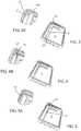
- FIG. 2is a rear perspective view of the wallet with a blank inserted in place of the cover;
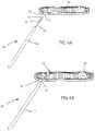
- FIG. 5is a perspective view showing the connection portion in a second position with FIG. 5A showing a detail of FIG. 5 ;
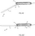
- FIG. 6Ais a schematic cross section showing the case and cover (without the tab) separate from one another;
- FIG. 6Cis a similar view showing the case and cover in the first position as shown in FIG. 4 ;
- FIG. 7is a cut-away perspective view showing a portion of the case, cover and connection portion
- FIG. 8is a plan view of the case with the cover closed
- FIG. 8Ais a cross section through A-A in FIG. 8 additionally showing the detail of the fastening device in a first position;
- FIG. 8Cis a view similar to FIGS. 8A and 8B showing the fastening device fully closed.
- the walletcomprises two main portions, the first of which is a case which largely corresponds to a conventional five sided case for a mobile electronic device.
- the second componentmay either be a cover as described below or a blank as illustrated in FIG. 2 . This will be described in greater detail below, but the only difference is that the cover has a portion which wraps around the front of the wallet while the blank does not.
- the blank illustrated in FIG. 2can equally be provided with the latching mechanism of the cover as described below.
- a recess 7(best shown in FIG. 3A ) is provided in the back of the case. This recess extends for most of the full height of the back of the case 1 and extends approximately a quarter of the way across the width of the back 2 .
- the left side 6can remain largely unaffected by the modification such that it retains ports and switches found on an unmodified case.
- the only part of the side 6 which may be affected by this modificationis the part which lies in the plane of the back 2 which is absent as described below.
- connection portion 14The third part of the cover 10 is the connection portion 14 .
- Thisis a rigid portion made in two pieces 15 , 16 as best shown in FIG. 7 . These two pieces sandwich the intermediate portion 13 between them to retain it in place. This defines a first edge 17 opposite to which is a free second edge 18 .
- a top edge 19 and a bottom edge 20extend between the first and second edges as best shown in FIGS. 1 and 3 .
- connection portion 14In order to attach the cover 10 to the case 1 , the connection portion 14 is pushed through the connection recess 7 initially pushing the slot 21 past the projection 23 in the position shown in FIGS. 3A and 6B . In this position, the recess 7 is long enough to receive the connection portion provided that it is inserted in a position away from the projections 23 . The connection portion 14 is then pulled back to the position shown in FIGS. 4 and 4A and 6C in which the projections 23 enter the slots 21 and then snap into the recesses 21 . This prevents the connection portion 14 from moving in anything other than a pivotal movement in which the connection portion 14 rotates about an axis 24 shown in FIG. 4A defined by the projections 23 .
- the deviceIn order to remove the cover 10 from the case 1 , the device first has to have been removed from the case.
- the engagement process described in FIGS. 3 to 5 (and 6 A to 6 D)is then reversed such that the connection portion is first pivoted to the first position shown in FIGS. 4 and 6C and is then pushed forward into the position shown in FIGS. 3 and 6B to disengage the projections 23 from the recesses 22 .
- Sufficient forceis required here in order to deflect the protrusions 23 such that they are forced out of the recesses 22 and along the slots 21 .
- connection portion 14is only made up of two moulded components, with the remaining features required to make the connection being moulded features either of the case or the connection portion, the wallet provides a low cost solution.
- Thiscomprises a three part material which results in a three layer structure forming the majority of the side wall as shown for side wall 5 in FIG. 6A to D.
- This three part structurecomprises an outer layer 30 of flexible polymer, and intermediate or dissipation layer 31 composed of dissipation material and an inner or damping layer 32 composed of damping material.
- the dissipation layer 31may be PC, ABS, PC/ABS blends, Hard TPU grades, glass and fibre-filled rigid thermoplastics, nylon, glass and fibre-filled nylons and similar materials.
- the inner layer 32may be a soft elastomer, soft TPU, TPE, silicone, foam or the like.
- the inner layer 32has a number of inwardly projecting ribs 33 which are configured to contact the device D such that there is generally no contact between the device and the case in the regions where the damping material is present other than through the ribs.
- the dissipation layer 31also extends to the vicinity of the recess 7 . It is arranged to form the perimeter of the recess at 7 as well as forming the projection 23 . If the projection is provided in the connection portion, and the slot is provided in the case, then the slot can be formed of the dissipation layer 31 . This ensures that a relatively ridged material forms the recess 7 and also provides engagement with the intermediate portion. This provides a more robust connection that using a softer material providing a more reliable connection which is less prone to damage.
- This arrangementprovides a simple construction, ease of use, a robust connection and low profile fastener.
Landscapes
- Engineering & Computer Science (AREA)
- Computer Networks & Wireless Communication (AREA)
- Signal Processing (AREA)
- Microelectronics & Electronic Packaging (AREA)
- Telephone Set Structure (AREA)
Abstract
Description
Claims (4)
Priority Applications (1)
| Application Number | Priority Date | Filing Date | Title |
|---|---|---|---|
| US15/591,875US10694630B2 (en) | 2017-05-10 | 2017-05-10 | Case for a mobile communications device with a screen |
Applications Claiming Priority (1)
| Application Number | Priority Date | Filing Date | Title |
|---|---|---|---|
| US15/591,875US10694630B2 (en) | 2017-05-10 | 2017-05-10 | Case for a mobile communications device with a screen |
Publications (2)
| Publication Number | Publication Date |
|---|---|
| US20180332724A1 US20180332724A1 (en) | 2018-11-15 |
| US10694630B2true US10694630B2 (en) | 2020-06-23 |
Family
ID=64097574
Family Applications (1)
| Application Number | Title | Priority Date | Filing Date |
|---|---|---|---|
| US15/591,875Active - ReinstatedUS10694630B2 (en) | 2017-05-10 | 2017-05-10 | Case for a mobile communications device with a screen |
Country Status (1)
| Country | Link |
|---|---|
| US (1) | US10694630B2 (en) |
Cited By (4)
| Publication number | Priority date | Publication date | Assignee | Title |
|---|---|---|---|---|
| USD908676S1 (en)* | 2019-04-25 | 2021-01-26 | Guangzhou Wenyi Communication Equipment Co., Ltd. | Mobile phone protective case |
| USD930640S1 (en)* | 2019-10-30 | 2021-09-14 | Changki YEO | Phone case |
| USD1042427S1 (en)* | 2022-11-03 | 2024-09-17 | Samsung Electronics Co., Ltd. | Case for electronic device |
| USD1096711S1 (en)* | 2017-08-10 | 2025-10-07 | Apple Inc. | Case for an electronic device |
Families Citing this family (7)
| Publication number | Priority date | Publication date | Assignee | Title |
|---|---|---|---|---|
| USD889453S1 (en) | 2017-09-08 | 2020-07-07 | Samsonite Ip Holdings S.Àr.L. | Case for an electronic device |
| USD889452S1 (en) | 2017-09-08 | 2020-07-07 | Samsonite Ip Holdings S.Àr.L. | Case for an electronic device |
| US10743630B2 (en) | 2017-09-08 | 2020-08-18 | Samsonite Ip Holdings S.Àr.L. | Dual-layer bumper for a case for a mobile device |
| US10694825B2 (en)* | 2017-09-08 | 2020-06-30 | Samsonite Ip Holdings S.Àr.L. | Tri-layer case with shock-absorbing impact geometry |
| US11522571B2 (en) | 2019-10-28 | 2022-12-06 | Speculative Product Design, Llc | Mobile device case with bonded soft resin insert and shell |
| USD949138S1 (en) | 2020-06-19 | 2022-04-19 | Speculative Product Design, Llc | Case for an electronic communications device |
| JP6842019B1 (en)* | 2020-08-25 | 2021-03-17 | 株式会社Pga | Mobile information terminal case |
Citations (47)
| Publication number | Priority date | Publication date | Assignee | Title |
|---|---|---|---|---|
| US5128829A (en)* | 1991-01-11 | 1992-07-07 | Health Innovations, Inc. | Hinge and stand for hand-held computer unit |
| US6634494B1 (en)* | 1996-07-18 | 2003-10-21 | Testo Ag | Watertight protective device for holding a measuring or display device |
| US20040173482A1 (en)* | 2003-03-05 | 2004-09-09 | Julian Nieves | PDA holding unit and holding case |
| US20040240164A1 (en)* | 2003-05-28 | 2004-12-02 | Tom Lee | Portable case for a notebook computer |
| US6967836B2 (en)* | 2003-01-30 | 2005-11-22 | Micro-Star Int'l Co., Ltd. | Device for accommodating a tablet PC |
| US20060007645A1 (en)* | 2004-07-09 | 2006-01-12 | Tatung Co., Ltd. | Foldable computer cover |
| US7318521B2 (en)* | 2004-09-21 | 2008-01-15 | Creative Technology Ltd | Pouch with integrated stand |
| US20080237432A1 (en)* | 2002-08-23 | 2008-10-02 | Case Logic, Inc. | Multi-Positionable Notebook Computer Case |
| US20090009945A1 (en)* | 2001-11-19 | 2009-01-08 | Jamie Lee Johnson | Protective enclosure for touch screen device |
| US7584841B2 (en)* | 2007-01-05 | 2009-09-08 | Belkin International, Inc. | Holding device for holding and positioning a portable object |
| US20100238119A1 (en)* | 2009-03-18 | 2010-09-23 | Zivthan Dubrovsky | Touchscreen Keyboard Overlay |
| US20100294683A1 (en)* | 2008-12-17 | 2010-11-25 | Patrick Mish | PLATFORM JACKET FOR AN eREADER |
| US20110034221A1 (en)* | 2009-08-06 | 2011-02-10 | Bekin International, Inc. | Case for electrical device and method of providing same |
| US20110297564A1 (en)* | 2010-06-03 | 2011-12-08 | Mozen Cna Co., Ltd. | Case for tablet personal computer |
| US20120043235A1 (en)* | 2010-08-23 | 2012-02-23 | James Robert Klement | Protective case for portable electrical device |
| US8132670B1 (en)* | 2011-03-16 | 2012-03-13 | E-Lead Electronics Co., Ltd. | Protective cover for portable electronic devices |
| US20120212896A1 (en)* | 2011-02-15 | 2012-08-23 | Daniel Helmut Schulz | Integrated computer case |
| US20120234716A1 (en)* | 2011-03-16 | 2012-09-20 | E-Lead Electronic Co., Ltd. | Adjustable protective cover for electronic device |
| US20120287565A1 (en)* | 2011-05-13 | 2012-11-15 | Lightwedge Llc | Case having an interchangeable cover |
| US20120298536A1 (en)* | 2011-05-25 | 2012-11-29 | Polar Electro Oy | Cover Mechanism for Casing |
| US8490783B1 (en)* | 2013-02-26 | 2013-07-23 | Eagle Fan | Protective cover |
| US20130213838A1 (en)* | 2012-01-06 | 2013-08-22 | Louis Hsuante TSAI | Adjustable holder for tablet computer and cover therefor |
| US20130264235A1 (en)* | 2012-04-09 | 2013-10-10 | Chia Hao LIN | Cell phone protection case structure |
| US20130334071A1 (en)* | 2005-01-28 | 2013-12-19 | Jeffrey D. Carnevali | Protective enclosure for touch screen device |
| US8727116B2 (en)* | 2010-10-06 | 2014-05-20 | Samsung Electronics Co., Ltd. | Protection cover for portable terminal |
| US8749960B2 (en)* | 2010-08-23 | 2014-06-10 | Belkin International, Inc. | Electronic device accessory and method of providing and using the same |
| US20140202890A1 (en)* | 2013-01-23 | 2014-07-24 | Targus Group International, Inc. | Dual support flap case |
| US20140216954A1 (en)* | 2007-06-06 | 2014-08-07 | Belkin International, Inc. | Case for electrical device and method of using same |
| US20140291176A1 (en)* | 2013-04-01 | 2014-10-02 | Marware, Inc. | Tablet Computer Cover and Stand |
| USD714550S1 (en)* | 2013-08-06 | 2014-10-07 | David & Young Group Corp. | Front fold mirror slot phone case |
| US20140347814A1 (en)* | 2013-04-19 | 2014-11-27 | Joseph A. Zaloom | Tablet transformer |
| US8899415B2 (en)* | 2012-04-09 | 2014-12-02 | Daymen Canada Acquisition Ulc | Electronic device case having variable angle stand |
| US8976536B2 (en)* | 2013-04-10 | 2015-03-10 | Lenovo Enterprise Solutions (Singapore) Pte. Ltd. | Latching cam handle assembly for securing mated circuit boards |
| US9010537B2 (en)* | 2010-11-04 | 2015-04-21 | Jeffrey D. Carnevali | Protective enclosure for touch screen device |
| US9078338B2 (en)* | 2012-07-24 | 2015-07-07 | Casio Computer Co., Ltd. | Protective cover for an electronic device |
| US20150195931A1 (en)* | 2014-01-03 | 2015-07-09 | Tech 21 Licensing Limited | Case for a portable device with a screen |
| USD734761S1 (en)* | 2013-12-20 | 2015-07-21 | Pelican Products, Inc. | Case for electronic pad |
| USD745013S1 (en)* | 2014-03-24 | 2015-12-08 | Malcolm Brierley | Case for an E-reader device with viewing stand and hand strap |
| US20160029759A1 (en)* | 2014-07-31 | 2016-02-04 | Iordanka Koleva Mulhern | Cradle-Cassette Apparatus for an Electronic Device |
| US20160157573A1 (en)* | 2014-12-04 | 2016-06-09 | Samsonite IP Holdings S.ar.I. | Case for an Electronic Device |
| US9380723B2 (en)* | 2010-10-12 | 2016-06-28 | Treefrog Developments, Inc. | Housing for encasing an electronic device |
| US20160211877A1 (en)* | 2014-11-13 | 2016-07-21 | Griffin Technology, Inc. | Customizable Device Case |
| USD765639S1 (en)* | 2015-06-17 | 2016-09-06 | Otter Products, Llc | Smartphone case |
| US20160316872A1 (en)* | 2015-04-28 | 2016-11-03 | World Richman Manufacturing Corporation | Grooved Case Construction for an Electronic Device |
| USD776645S1 (en)* | 2014-12-04 | 2017-01-17 | Samsonite IP Holdings S.à.r.l. | Case for an electronic device |
| US9559741B2 (en)* | 2011-06-13 | 2017-01-31 | Treefrog Developments, Inc. | Housing for encasing a mobile computing device |
| USD777421S1 (en)* | 2015-07-30 | 2017-01-31 | Griffin Technology, Inc. | Wallet style portable electronic device case |
- 2017
- 2017-05-10USUS15/591,875patent/US10694630B2/enactiveActive - Reinstated
Patent Citations (48)
| Publication number | Priority date | Publication date | Assignee | Title |
|---|---|---|---|---|
| US5128829A (en)* | 1991-01-11 | 1992-07-07 | Health Innovations, Inc. | Hinge and stand for hand-held computer unit |
| US6634494B1 (en)* | 1996-07-18 | 2003-10-21 | Testo Ag | Watertight protective device for holding a measuring or display device |
| US20090009945A1 (en)* | 2001-11-19 | 2009-01-08 | Jamie Lee Johnson | Protective enclosure for touch screen device |
| US20080237432A1 (en)* | 2002-08-23 | 2008-10-02 | Case Logic, Inc. | Multi-Positionable Notebook Computer Case |
| US6967836B2 (en)* | 2003-01-30 | 2005-11-22 | Micro-Star Int'l Co., Ltd. | Device for accommodating a tablet PC |
| US20040173482A1 (en)* | 2003-03-05 | 2004-09-09 | Julian Nieves | PDA holding unit and holding case |
| US20040240164A1 (en)* | 2003-05-28 | 2004-12-02 | Tom Lee | Portable case for a notebook computer |
| US20060007645A1 (en)* | 2004-07-09 | 2006-01-12 | Tatung Co., Ltd. | Foldable computer cover |
| US7318521B2 (en)* | 2004-09-21 | 2008-01-15 | Creative Technology Ltd | Pouch with integrated stand |
| US20130334071A1 (en)* | 2005-01-28 | 2013-12-19 | Jeffrey D. Carnevali | Protective enclosure for touch screen device |
| US7584841B2 (en)* | 2007-01-05 | 2009-09-08 | Belkin International, Inc. | Holding device for holding and positioning a portable object |
| US20140216954A1 (en)* | 2007-06-06 | 2014-08-07 | Belkin International, Inc. | Case for electrical device and method of using same |
| US20100294683A1 (en)* | 2008-12-17 | 2010-11-25 | Patrick Mish | PLATFORM JACKET FOR AN eREADER |
| US20100238119A1 (en)* | 2009-03-18 | 2010-09-23 | Zivthan Dubrovsky | Touchscreen Keyboard Overlay |
| US20110034221A1 (en)* | 2009-08-06 | 2011-02-10 | Bekin International, Inc. | Case for electrical device and method of providing same |
| US20110297564A1 (en)* | 2010-06-03 | 2011-12-08 | Mozen Cna Co., Ltd. | Case for tablet personal computer |
| US20120043235A1 (en)* | 2010-08-23 | 2012-02-23 | James Robert Klement | Protective case for portable electrical device |
| US8749960B2 (en)* | 2010-08-23 | 2014-06-10 | Belkin International, Inc. | Electronic device accessory and method of providing and using the same |
| US8727116B2 (en)* | 2010-10-06 | 2014-05-20 | Samsung Electronics Co., Ltd. | Protection cover for portable terminal |
| US9380723B2 (en)* | 2010-10-12 | 2016-06-28 | Treefrog Developments, Inc. | Housing for encasing an electronic device |
| US9010537B2 (en)* | 2010-11-04 | 2015-04-21 | Jeffrey D. Carnevali | Protective enclosure for touch screen device |
| US20120212896A1 (en)* | 2011-02-15 | 2012-08-23 | Daniel Helmut Schulz | Integrated computer case |
| US20120234716A1 (en)* | 2011-03-16 | 2012-09-20 | E-Lead Electronic Co., Ltd. | Adjustable protective cover for electronic device |
| US8132670B1 (en)* | 2011-03-16 | 2012-03-13 | E-Lead Electronics Co., Ltd. | Protective cover for portable electronic devices |
| US20120287565A1 (en)* | 2011-05-13 | 2012-11-15 | Lightwedge Llc | Case having an interchangeable cover |
| US8929057B2 (en)* | 2011-05-25 | 2015-01-06 | Polar Electro Oy | Cover mechanism for casing |
| US20120298536A1 (en)* | 2011-05-25 | 2012-11-29 | Polar Electro Oy | Cover Mechanism for Casing |
| US9559741B2 (en)* | 2011-06-13 | 2017-01-31 | Treefrog Developments, Inc. | Housing for encasing a mobile computing device |
| US20130213838A1 (en)* | 2012-01-06 | 2013-08-22 | Louis Hsuante TSAI | Adjustable holder for tablet computer and cover therefor |
| US20130264235A1 (en)* | 2012-04-09 | 2013-10-10 | Chia Hao LIN | Cell phone protection case structure |
| US8899415B2 (en)* | 2012-04-09 | 2014-12-02 | Daymen Canada Acquisition Ulc | Electronic device case having variable angle stand |
| US9078338B2 (en)* | 2012-07-24 | 2015-07-07 | Casio Computer Co., Ltd. | Protective cover for an electronic device |
| US20140202890A1 (en)* | 2013-01-23 | 2014-07-24 | Targus Group International, Inc. | Dual support flap case |
| US8490783B1 (en)* | 2013-02-26 | 2013-07-23 | Eagle Fan | Protective cover |
| US20140291176A1 (en)* | 2013-04-01 | 2014-10-02 | Marware, Inc. | Tablet Computer Cover and Stand |
| US8976536B2 (en)* | 2013-04-10 | 2015-03-10 | Lenovo Enterprise Solutions (Singapore) Pte. Ltd. | Latching cam handle assembly for securing mated circuit boards |
| US20140347814A1 (en)* | 2013-04-19 | 2014-11-27 | Joseph A. Zaloom | Tablet transformer |
| USD714550S1 (en)* | 2013-08-06 | 2014-10-07 | David & Young Group Corp. | Front fold mirror slot phone case |
| USD734761S1 (en)* | 2013-12-20 | 2015-07-21 | Pelican Products, Inc. | Case for electronic pad |
| US20150195931A1 (en)* | 2014-01-03 | 2015-07-09 | Tech 21 Licensing Limited | Case for a portable device with a screen |
| USD745013S1 (en)* | 2014-03-24 | 2015-12-08 | Malcolm Brierley | Case for an E-reader device with viewing stand and hand strap |
| US20160029759A1 (en)* | 2014-07-31 | 2016-02-04 | Iordanka Koleva Mulhern | Cradle-Cassette Apparatus for an Electronic Device |
| US20160211877A1 (en)* | 2014-11-13 | 2016-07-21 | Griffin Technology, Inc. | Customizable Device Case |
| US20160157573A1 (en)* | 2014-12-04 | 2016-06-09 | Samsonite IP Holdings S.ar.I. | Case for an Electronic Device |
| USD776645S1 (en)* | 2014-12-04 | 2017-01-17 | Samsonite IP Holdings S.à.r.l. | Case for an electronic device |
| US20160316872A1 (en)* | 2015-04-28 | 2016-11-03 | World Richman Manufacturing Corporation | Grooved Case Construction for an Electronic Device |
| USD765639S1 (en)* | 2015-06-17 | 2016-09-06 | Otter Products, Llc | Smartphone case |
| USD777421S1 (en)* | 2015-07-30 | 2017-01-31 | Griffin Technology, Inc. | Wallet style portable electronic device case |
Cited By (4)
| Publication number | Priority date | Publication date | Assignee | Title |
|---|---|---|---|---|
| USD1096711S1 (en)* | 2017-08-10 | 2025-10-07 | Apple Inc. | Case for an electronic device |
| USD908676S1 (en)* | 2019-04-25 | 2021-01-26 | Guangzhou Wenyi Communication Equipment Co., Ltd. | Mobile phone protective case |
| USD930640S1 (en)* | 2019-10-30 | 2021-09-14 | Changki YEO | Phone case |
| USD1042427S1 (en)* | 2022-11-03 | 2024-09-17 | Samsung Electronics Co., Ltd. | Case for electronic device |
Also Published As
| Publication number | Publication date |
|---|---|
| US20180332724A1 (en) | 2018-11-15 |
Similar Documents
| Publication | Publication Date | Title |
|---|---|---|
| US10694630B2 (en) | Case for a mobile communications device with a screen | |
| US5682910A (en) | Cosmetic case with push button defined and surrounded by an elastically deformable annular groove | |
| US20080083517A1 (en) | Door shutter | |
| KR100868394B1 (en) | Wet tissue container with one touch open | |
| EP2351692B1 (en) | Freely opened/closed container | |
| US7703627B2 (en) | Vanity case | |
| CN107681345B (en) | Electrical connector assembly | |
| US7870862B2 (en) | Vanity case | |
| KR20040003343A (en) | Folder of mobile terminal | |
| US4448327A (en) | Plastic container having a concealed hinge | |
| US7314052B2 (en) | Vanity case | |
| CN206327277U (en) | Device for keeping electronic equipment | |
| KR20130004222U (en) | Smart phone case having cover | |
| US12139305B2 (en) | Extruded spring strap for container and packaging applications | |
| WO2023041914A1 (en) | A mobile phone case | |
| US20040143944A1 (en) | Elastic buckle | |
| JP4911511B2 (en) | One-touch cap | |
| JP7218133B2 (en) | Household tissue paper storage container | |
| JPH0928485A (en) | Hand rest member | |
| JP7206068B2 (en) | Household tissue paper storage container | |
| KR200473933Y1 (en) | A Case for a portable electronics | |
| CN107305990B (en) | Door cover of electronic device | |
| JPH08205925A (en) | Cosmetic container | |
| CN110817203A (en) | Uncovering structure, garbage can cover assembly and garbage can | |
| JPH09140441A (en) | Cosmetic container |
Legal Events
| Date | Code | Title | Description |
|---|---|---|---|
| AS | Assignment | Owner name:TECH 21 LICENSING LIMITED, UNITED KINGDOM Free format text:ASSIGNMENT OF ASSIGNORS INTEREST;ASSIGNORS:ROBERTS, JASON;THORPE, BENJAMIN;SIGNING DATES FROM 20170605 TO 20170606;REEL/FRAME:043195/0756 | |
| STPP | Information on status: patent application and granting procedure in general | Free format text:RESPONSE TO NON-FINAL OFFICE ACTION ENTERED AND FORWARDED TO EXAMINER | |
| STPP | Information on status: patent application and granting procedure in general | Free format text:NON FINAL ACTION MAILED | |
| STPP | Information on status: patent application and granting procedure in general | Free format text:RESPONSE TO NON-FINAL OFFICE ACTION ENTERED AND FORWARDED TO EXAMINER | |
| STPP | Information on status: patent application and granting procedure in general | Free format text:NOTICE OF ALLOWANCE MAILED -- APPLICATION RECEIVED IN OFFICE OF PUBLICATIONS | |
| STCF | Information on status: patent grant | Free format text:PATENTED CASE | |
| FEPP | Fee payment procedure | Free format text:MAINTENANCE FEE REMINDER MAILED (ORIGINAL EVENT CODE: REM.); ENTITY STATUS OF PATENT OWNER: LARGE ENTITY | |
| LAPS | Lapse for failure to pay maintenance fees | Free format text:PATENT EXPIRED FOR FAILURE TO PAY MAINTENANCE FEES (ORIGINAL EVENT CODE: EXP.); ENTITY STATUS OF PATENT OWNER: LARGE ENTITY | |
| PRDP | Patent reinstated due to the acceptance of a late maintenance fee | Effective date:20240801 | |
| FEPP | Fee payment procedure | Free format text:ENTITY STATUS SET TO SMALL (ORIGINAL EVENT CODE: SMAL); ENTITY STATUS OF PATENT OWNER: SMALL ENTITY Free format text:PETITION RELATED TO MAINTENANCE FEES FILED (ORIGINAL EVENT CODE: PMFP); ENTITY STATUS OF PATENT OWNER: SMALL ENTITY Free format text:PETITION RELATED TO MAINTENANCE FEES GRANTED (ORIGINAL EVENT CODE: PMFG); ENTITY STATUS OF PATENT OWNER: SMALL ENTITY Free format text:SURCHARGE, PETITION TO ACCEPT PYMT AFTER EXP, UNINTENTIONAL. (ORIGINAL EVENT CODE: M2558); ENTITY STATUS OF PATENT OWNER: SMALL ENTITY | |
| MAFP | Maintenance fee payment | Free format text:PAYMENT OF MAINTENANCE FEE, 4TH YR, SMALL ENTITY (ORIGINAL EVENT CODE: M2551); ENTITY STATUS OF PATENT OWNER: SMALL ENTITY Year of fee payment:4 | |
| STCF | Information on status: patent grant | Free format text:PATENTED CASE | |
| FP | Lapsed due to failure to pay maintenance fee | Effective date:20240623 |