US10693052B2 - System and method for energy harvesting in a data center - Google Patents
System and method for energy harvesting in a data centerDownload PDFInfo
- Publication number
- US10693052B2 US10693052B2US14/442,645US201314442645AUS10693052B2US 10693052 B2US10693052 B2US 10693052B2US 201314442645 AUS201314442645 AUS 201314442645AUS 10693052 B2US10693052 B2US 10693052B2
- Authority
- US
- United States
- Prior art keywords
- data center
- waste heat
- thermoelectric device
- power feed
- collection device
- Prior art date
- Legal status (The legal status is an assumption and is not a legal conclusion. Google has not performed a legal analysis and makes no representation as to the accuracy of the status listed.)
- Active, expires
Links
Images


Classifications
- H01L35/30—
- H—ELECTRICITY
- H05—ELECTRIC TECHNIQUES NOT OTHERWISE PROVIDED FOR
- H05K—PRINTED CIRCUITS; CASINGS OR CONSTRUCTIONAL DETAILS OF ELECTRIC APPARATUS; MANUFACTURE OF ASSEMBLAGES OF ELECTRICAL COMPONENTS
- H05K7/00—Constructional details common to different types of electric apparatus
- H05K7/20—Modifications to facilitate cooling, ventilating, or heating
- H05K7/20709—Modifications to facilitate cooling, ventilating, or heating for server racks or cabinets; for data centers, e.g. 19-inch computer racks
- H05K7/20718—Forced ventilation of a gaseous coolant
- H05K7/20736—Forced ventilation of a gaseous coolant within cabinets for removing heat from server blades
- H01L35/02—
- H—ELECTRICITY
- H05—ELECTRIC TECHNIQUES NOT OTHERWISE PROVIDED FOR
- H05K—PRINTED CIRCUITS; CASINGS OR CONSTRUCTIONAL DETAILS OF ELECTRIC APPARATUS; MANUFACTURE OF ASSEMBLAGES OF ELECTRICAL COMPONENTS
- H05K7/00—Constructional details common to different types of electric apparatus
- H05K7/20—Modifications to facilitate cooling, ventilating, or heating
- H05K7/20709—Modifications to facilitate cooling, ventilating, or heating for server racks or cabinets; for data centers, e.g. 19-inch computer racks
- H05K7/20718—Forced ventilation of a gaseous coolant
- H05K7/20745—Forced ventilation of a gaseous coolant within rooms for removing heat from cabinets, e.g. by air conditioning device
- H—ELECTRICITY
- H10—SEMICONDUCTOR DEVICES; ELECTRIC SOLID-STATE DEVICES NOT OTHERWISE PROVIDED FOR
- H10N—ELECTRIC SOLID-STATE DEVICES NOT OTHERWISE PROVIDED FOR
- H10N10/00—Thermoelectric devices comprising a junction of dissimilar materials, i.e. devices exhibiting Seebeck or Peltier effects
- H10N10/10—Thermoelectric devices comprising a junction of dissimilar materials, i.e. devices exhibiting Seebeck or Peltier effects operating with only the Peltier or Seebeck effects
- H10N10/13—Thermoelectric devices comprising a junction of dissimilar materials, i.e. devices exhibiting Seebeck or Peltier effects operating with only the Peltier or Seebeck effects characterised by the heat-exchanging means at the junction
- H—ELECTRICITY
- H10—SEMICONDUCTOR DEVICES; ELECTRIC SOLID-STATE DEVICES NOT OTHERWISE PROVIDED FOR
- H10N—ELECTRIC SOLID-STATE DEVICES NOT OTHERWISE PROVIDED FOR
- H10N10/00—Thermoelectric devices comprising a junction of dissimilar materials, i.e. devices exhibiting Seebeck or Peltier effects
- H10N10/80—Constructional details
- H—ELECTRICITY
- H10—SEMICONDUCTOR DEVICES; ELECTRIC SOLID-STATE DEVICES NOT OTHERWISE PROVIDED FOR
- H10N—ELECTRIC SOLID-STATE DEVICES NOT OTHERWISE PROVIDED FOR
- H10N10/00—Thermoelectric devices comprising a junction of dissimilar materials, i.e. devices exhibiting Seebeck or Peltier effects
- Y—GENERAL TAGGING OF NEW TECHNOLOGICAL DEVELOPMENTS; GENERAL TAGGING OF CROSS-SECTIONAL TECHNOLOGIES SPANNING OVER SEVERAL SECTIONS OF THE IPC; TECHNICAL SUBJECTS COVERED BY FORMER USPC CROSS-REFERENCE ART COLLECTIONS [XRACs] AND DIGESTS
- Y02—TECHNOLOGIES OR APPLICATIONS FOR MITIGATION OR ADAPTATION AGAINST CLIMATE CHANGE
- Y02D—CLIMATE CHANGE MITIGATION TECHNOLOGIES IN INFORMATION AND COMMUNICATION TECHNOLOGIES [ICT], I.E. INFORMATION AND COMMUNICATION TECHNOLOGIES AIMING AT THE REDUCTION OF THEIR OWN ENERGY USE
- Y02D10/00—Energy efficient computing, e.g. low power processors, power management or thermal management
Definitions
- the present applicationis directed to a system and method for energy harvesting in a data center.
- a typical data centeroperates at around a power usage effectiveness (PUE) of about 2.0 which indicates that the data center's overall power demand is about two times greater than the Information Technology (IT) equipment load.
- PUEpower usage effectiveness
- ITInformation Technology
- An object of the present inventionis to provide a system and method for harvesting waste heat generated by data center operations.
- the energy harvesting systemgenerates from the waste heat, electricity usable by computing devices in the data center. In this way, the energy harvesting system is able to recycle waste heat energy that would otherwise be lost, and use that energy to power information technology equipment in the data center.
- the energy harvesting systemhas one or more collection devices, a thermoelectric device and a controller.
- the one or more collection devicesdirect waste heat and room temperature air in the data center into a thermoelectric device.
- the thermoelectric devicereceives the waste heat and room temperature air as input, interprets a temperature gradient between the waste heat and room temperature air, and generates from the temperature gradient an electrical potential as an output.
- the controllerdirects the conversion of the thermoelectric device-generated electrical potential to usable electricity and combines the usable electricity combinable with utility-input electricity to deliver power to the computing devices in the data center.
- thermoelectric devicea. directing waste heat expelled by computing devices in said data center into a thermoelectric device
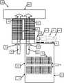
- FIG. 1is a schematic view of a first embodiment of a data center having a an energy harvesting system embodied in accordance with the present invention
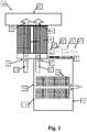
- FIG. 2is a schematic view of a second embodiment of the energy harvesting system in a data center having a chilled water loop;
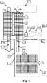
- FIG. 3shows an alternate arrangement of the first embodiment of the energy harvesting system of FIG. 1 ;
- FIG. 4shows the energy and data flow between the energy harvesting, IT and building management equipment and devices in the data center.
- FIG. 1A first embodiment of an energy harvesting system 20 for recovering waste heat in a data center 100 is shown in FIG. 1 .
- the energy harvesting system 20recovers the waste heat generated by data center 100 operations, transforms the waste heat into usable energy, and provides the usable energy for consumption by the electronic devices and other equipment in the data center 100 .
- the data center 100is comprised of racks of servers 50 such as application, network and other types of servers, devices such as power distribution units, batteries, rectifiers, inverters, computer room air handlers (CRAH), computer room air conditioners (CRAC), transformers, generators and other equipment necessary for conducting the operations of a data center.
- servers 50such as application, network and other types of servers, devices such as power distribution units, batteries, rectifiers, inverters, computer room air handlers (CRAH), computer room air conditioners (CRAC), transformers, generators and other equipment necessary for conducting the operations of a data center.
- servers 50such as application, network and other types of servers, devices such as power distribution units, batteries, rectifiers, inverters, computer room air handlers (CRAH), computer room air conditioners (CRAC), transformers, generators and other equipment necessary for conducting the operations of a data center.
- devicessuch as power distribution units, batteries, rectifiers, inverters, computer room air handlers (CRAH), computer room air conditioners (CRAC), transformer
- the data center 100occupies an enclosed space such as a room in a building, an entire building, a transportable container such as a shipping container for land or water transport, an underground location or any type of enclosure or environment that protects the computing equipment from heat, moisture, and other factors detrimental to the operation of computing equipment.
- Each server 50 rackis enclosed by a cabinet having a vented front door.
- multiple server racksare provided in a room having four walls, and upon the front wall is mounted a door 10 that is vented.
- the door 10is formed from fiber-reinforced plastic, metal or another suitable material and may be perforated or otherwise vented for permitting the passage of air between the data center 100 and the surrounding environment or building.
- the data center 100operates at about a power utilization effectiveness (PUE) of 2.0.
- PUErepresented the total power to the data center 100 divided by the power consumed by the IT equipment.
- a second one-Watt of poweris used by the facility equipment to cool and otherwise support the computing equipment.
- the energy harvesting system 20is capable to reduce the energy requirements and/or IT equipment load by generating power from the recovered waste heat.
- the amount of power generatedis dependent upon the efficiency of the thermoelectric device 38 .
- a resulting two-Watts of overall power savings for the data centeris realized.
- the energy harvesting system 20is comprised of a thermoelectric device 38 , one or more collection units 22 , 24 and a controller 70 .
- the energy harvesting system 20produces usable energy from waste heat and combines the usable energy with utility-input energy 60 to power the data center 100 partially or completely depending on the installation.
- the thermoelectric device 38may be a heat pump, heat exchanger, or any solid state device capable of utilizing a temperature gradient for heat transfer and energy recovery.
- Hot exhaust air, or waste heat 14is expelled from servers 50 and other IT/computing equipment as the servers 50 consume power during operation and performance of computational tasks.
- the waste heat 14measures about 45 degrees Celsius.
- the waste heat 14is contained in the data center 100 by a solid door 12 at the rear of the data center 100 . Further, rack spacers are also used to fill empty positions between servers 50 in the rack, preventing the waste heat 14 from being contained in the empty positions.
- the solid door 12may be located opposite the vented door 10 in the data center 100 .
- Room temperature air 15is circulating through the data center 100 at about 25 degrees Celsius at the same time the waste heat 14 is being generated.
- the waste heat 14 and room temperature air 15are directed over heat sinks 23 , 27 and further into the thermoelectric device 38 by one or more collection units 22 , 24 such as variable speed exhaust fans, outflow fans and fans internal to the servers.
- the one or more collection devices 22 , 24harness and direct the waste heat 14 and room temperature air 20 into the thermoelectric device 38 .
- the thermoelectric device 38receives the waste heat 14 and room temperature air 15 and detects a temperature gradient between the waste heat 14 and room temperature air 15 . The greater the temperature gradient between the room temperature air 15 and the waste heat 14 , the greater the direct current (DC) electrical energy that is produced at the output of the thermoelectric device 38 .
- the thermoelectric device 38converts the waste heat 14 and room temperature air 15 into an electrical potential. The electrical potential is interpreted, conditioned and distributed by a controller 70 .
- the controller 70is comprised of a central processing unit, memory, communication interfaces, digital and analog inputs and outputs, and a power converter.
- the controller 70executes purpose built and/or general purpose software which direct the overall operations of the energy harvesting system 20 and general data center 100 operations.
- the communication interfaces of the controller 70provide serial communication between a pair of redundant controllers and to the data center infrastructure management (DCIM) and other supervisory systems.
- the controller 70has interfaces and software that collects measurement data from a set of sensors installed in the data center itself and equipment within the data center. The sensors provide environmental, electrical and physical security data.
- the controller 70has interfaces and software to control the operation of electrical breakers, protection equipment, and fans such as the variable speed exhaust fans referred to above.
- the controller 70uses an internal electrical bus to combine electrical power from the power feed 60 , with power from the thermoelectric device 38 and the energy storage device 66 to deliver power to the servers 50 using the power distribution functionality.
- the controller 70also delivers power to the energy storage device 66 .
- a control algorithmdetermines the amount of electrical energy consumed by the servers 50 , protective equipment, data center cooling equipment, building management system, and other devices in the data center.
- the control algorithmfurther distributes to each heat sink in the data center in such a way as to minimize the electrical energy from the power feed 60 .
- Another control algorithmdetermines the appropriate fan speed to ensure the internal pressure of the server 50 cabinet is equal to the ambient air pressure in the data center 100 , room, or compartment within the data center 100 housing the server 50 cabinet in order to optimize the flow of air through the computer servers 50 and thermoelectric device 38 .
- the software stored in a computer-readable medium or otherwise in the controller 70further collects and measures data, computes analytics of the data and records both the raw measurements and the analytics in a database arranged to preserve historical records of the data.
- the controller 70 softwareprovides communication protocols which allow the transmission of measurement data and analytics to other systems as well as accepting supervisory control commands from other systems such as supervisory control and data acquisition (SCADA) and building management systems (BMS).
- SCADAsupervisory control and data acquisition
- BMSbuilding management systems
- thermoelectric device 38The electrical energy recovered by the thermoelectric device 38 at the direction of the controller 70 is then added to an input energy source such as a utility-provided energy input 60 .
- an input energy sourcesuch as a utility-provided energy input 60 .
- a portion of the DC power generated by the thermoelectric device 38is stored in an energy storage module 66 .
- the energy storage module 66provides at least sixty (60) seconds of backup power to the data center 100 servers 50 and other equipment in the event of loss of primary and secondary power feeds to the data center 100 .
- the inverter 64it is necessary to pass the output power of the inverter 64 through a filter 62 before combining the recovered energy (recovered from the conversion of the waste heat to usable energy) with utility-input power.
- the AC power at the output of the inverter 64is then fed back into the data center 100 to power the servers 50 and other equipment in the data center 100 such as CRAHs and CRACs.
- thermoelectric device 38expels exhaust air streams 26 , 28 that are further directed into a return plenum 40 .
- the return plenum 40routes the now-combined exhaust air streams 26 , 28 to the CRAH or CRAC, thereby forming a closed cooling loop.
- the second embodiment of the energy harvesting system 20utilizes a chilled water loop 48 to create a greater temperature gradient across the thermoelectric device 38 .
- the chilled water supply 48is about 10 degrees Celsius and the waste heat 14 generated at the output of the computer (IT) equipment in the data center 100 is about 45 degrees Celsius.
- the greater temperature gradientallows to the thermoelectric device 38 at the direction of the controller 70 to generate more power from the conversion of the input streams 48 , 14 .
- the third embodimentuses cool air 27 generated by a CRAH or CRAC located inside the data center 100 .
- the cool air 27may be generated in a room separated from the data center 100 main operational room by walls or partitions.
- the data flow in the data center 100follows a path wherein all devices (servers, fan drivers, thermal, environmental, power and security sensors) transmit data and/or signals to the primary controller 70 .
- the primary controller 70uses Ethernet communications to enable direct integration into a Data Center Infrastructure Management (DCIM) system and thereby control the power distribution, energy management, server rack monitoring, and building management conditions (such as power, temperature, humidity, airflow, smoke detection, leak detection and data center entry security).
- DCIMData Center Infrastructure Management
- the primary controller 70interprets the sensor data and directs the power distribution modules and operation of the fan drives of the one or more collection devices 22 , 24 and thermoelectric device 38 .
Landscapes
- Engineering & Computer Science (AREA)
- Computer Hardware Design (AREA)
- General Engineering & Computer Science (AREA)
- Physics & Mathematics (AREA)
- Thermal Sciences (AREA)
- Microelectronics & Electronic Packaging (AREA)
- Air Conditioning Control Device (AREA)
- Feedback Control In General (AREA)
Abstract
Description
Claims (13)
Priority Applications (1)
| Application Number | Priority Date | Filing Date | Title |
|---|---|---|---|
| US14/442,645US10693052B2 (en) | 2012-11-26 | 2013-11-25 | System and method for energy harvesting in a data center |
Applications Claiming Priority (3)
| Application Number | Priority Date | Filing Date | Title |
|---|---|---|---|
| US201261729955P | 2012-11-26 | 2012-11-26 | |
| PCT/US2013/071603WO2014082028A1 (en) | 2012-11-26 | 2013-11-25 | System and method for energy harvesting in a data center |
| US14/442,645US10693052B2 (en) | 2012-11-26 | 2013-11-25 | System and method for energy harvesting in a data center |
Publications (3)
| Publication Number | Publication Date |
|---|---|
| US20160284962A1 US20160284962A1 (en) | 2016-09-29 |
| US20180013049A9 US20180013049A9 (en) | 2018-01-11 |
| US10693052B2true US10693052B2 (en) | 2020-06-23 |
Family
ID=49759589
Family Applications (1)
| Application Number | Title | Priority Date | Filing Date |
|---|---|---|---|
| US14/442,645Active2034-12-23US10693052B2 (en) | 2012-11-26 | 2013-11-25 | System and method for energy harvesting in a data center |
Country Status (4)
| Country | Link |
|---|---|
| US (1) | US10693052B2 (en) |
| CA (1) | CA2892354A1 (en) |
| GB (1) | GB2525325B (en) |
| WO (1) | WO2014082028A1 (en) |
Cited By (1)
| Publication number | Priority date | Publication date | Assignee | Title |
|---|---|---|---|---|
| US20220312646A1 (en)* | 2021-03-26 | 2022-09-29 | Baidu Usa Llc | Thermal management system and method for power optimization for cooling an electronic rack |
Families Citing this family (18)
| Publication number | Priority date | Publication date | Assignee | Title |
|---|---|---|---|---|
| AU2009308467A1 (en) | 2008-10-21 | 2010-04-29 | Raritan Americas, Inc. | Methods of achieving cognizant power management |
| US10141492B2 (en) | 2015-05-14 | 2018-11-27 | Nimbus Materials Inc. | Energy harvesting for wearable technology through a thin flexible thermoelectric device |
| US10367131B2 (en) | 2013-12-06 | 2019-07-30 | Sridhar Kasichainula | Extended area of sputter deposited n-type and p-type thermoelectric legs in a flexible thin-film based thermoelectric device |
| US10290794B2 (en) | 2016-12-05 | 2019-05-14 | Sridhar Kasichainula | Pin coupling based thermoelectric device |
| US11024789B2 (en) | 2013-12-06 | 2021-06-01 | Sridhar Kasichainula | Flexible encapsulation of a flexible thin-film based thermoelectric device with sputter deposited layer of N-type and P-type thermoelectric legs |
| US20180090660A1 (en) | 2013-12-06 | 2018-03-29 | Sridhar Kasichainula | Flexible thin-film based thermoelectric device with sputter deposited layer of n-type and p-type thermoelectric legs |
| US10566515B2 (en) | 2013-12-06 | 2020-02-18 | Sridhar Kasichainula | Extended area of sputter deposited N-type and P-type thermoelectric legs in a flexible thin-film based thermoelectric device |
| HK1243522A1 (en) | 2014-11-04 | 2018-07-13 | Lo3能源有限公司 | Use of computationally generated thermal energy |
| US10164464B1 (en)* | 2015-03-12 | 2018-12-25 | Amazon Technologies, Inc. | Modular uninterruptible power supply |
| US9832912B2 (en)* | 2015-05-07 | 2017-11-28 | Dhk Storage, Llc | Computer server heat regulation utilizing integrated precision air flow |
| US11283000B2 (en) | 2015-05-14 | 2022-03-22 | Nimbus Materials Inc. | Method of producing a flexible thermoelectric device to harvest energy for wearable applications |
| US11276810B2 (en) | 2015-05-14 | 2022-03-15 | Nimbus Materials Inc. | Method of producing a flexible thermoelectric device to harvest energy for wearable applications |
| US11076509B2 (en) | 2017-01-24 | 2021-07-27 | The Research Foundation for the State University | Control systems and prediction methods for it cooling performance in containment |
| EP3431263B1 (en) | 2017-07-21 | 2021-04-21 | CL Schutzrechtsverwaltungs GmbH | Method for operating at least one apparatus for additively manufacturing three-dimensional objects |
| US11856686B1 (en)* | 2018-11-28 | 2023-12-26 | Nautilus True, Llc | Submerged data center facility system and method |
| US11496073B2 (en)* | 2019-06-28 | 2022-11-08 | Cupertino Electric, Inc. | Recovering small scale energy in electronic systems |
| US10998483B1 (en)* | 2019-10-23 | 2021-05-04 | Microsoft Technology Licensing, Llc | Energy regeneration in fuel cell-powered datacenter with thermoelectric generators |
| CN116916634B (en)* | 2023-09-11 | 2023-12-19 | 四川川西数据产业有限公司 | Heat energy recovery system and method for data center |
Citations (11)
| Publication number | Priority date | Publication date | Assignee | Title |
|---|---|---|---|---|
| US20020139123A1 (en)* | 2001-02-09 | 2002-10-03 | Bell Lon E. | Efficiency thermoelectrics utilizing thermal isolation |
| US7242580B1 (en) | 2005-12-28 | 2007-07-10 | Hitachi, Ltd. | Disk array apparatus |
| US20080209237A1 (en)* | 2007-02-23 | 2008-08-28 | Samsung Electronics Co., Ltd | Computer apparatus and power supply method thereof |
| US20100043858A1 (en)* | 2008-08-20 | 2010-02-25 | International Business Machines Corporation | Power generation system for an electronic system |
| US20100216388A1 (en)* | 2006-04-27 | 2010-08-26 | Wright Line Llc | Systems and Methods for Closed Loop Heat Containment with Cold Aisle Isolation for Data Center Cooling |
| US20120152298A1 (en)* | 2010-12-17 | 2012-06-21 | International Business Machines Corporation | Rack mounted thermoelectric generator assemblies for passively generating electricity within a data center |
| US20120279233A1 (en) | 2011-05-06 | 2012-11-08 | International Business Machines Corporation | Thermoelectric-enhanced, liquid-based cooling of a multi-component electronic system |
| US20120298334A1 (en)* | 2011-05-27 | 2012-11-29 | Stephen Madaffari | Air Cooling Unit For Data Centers |
| US20120306274A1 (en)* | 2011-06-03 | 2012-12-06 | Liebert Corporation | Ups adaptive output voltage control systems |
| US20130300266A1 (en)* | 2012-05-11 | 2013-11-14 | Panduit Corp. | Modular Containment System |
| US9041250B1 (en)* | 2012-03-15 | 2015-05-26 | Amazon Technologies, Inc. | System and method for maintaining power to electrical systems |
- 2013
- 2013-11-25USUS14/442,645patent/US10693052B2/enactiveActive
- 2013-11-25CACA2892354Apatent/CA2892354A1/ennot_activeAbandoned
- 2013-11-25GBGB1508244.9Apatent/GB2525325B/enactiveActive
- 2013-11-25WOPCT/US2013/071603patent/WO2014082028A1/enactiveApplication Filing
Patent Citations (11)
| Publication number | Priority date | Publication date | Assignee | Title |
|---|---|---|---|---|
| US20020139123A1 (en)* | 2001-02-09 | 2002-10-03 | Bell Lon E. | Efficiency thermoelectrics utilizing thermal isolation |
| US7242580B1 (en) | 2005-12-28 | 2007-07-10 | Hitachi, Ltd. | Disk array apparatus |
| US20100216388A1 (en)* | 2006-04-27 | 2010-08-26 | Wright Line Llc | Systems and Methods for Closed Loop Heat Containment with Cold Aisle Isolation for Data Center Cooling |
| US20080209237A1 (en)* | 2007-02-23 | 2008-08-28 | Samsung Electronics Co., Ltd | Computer apparatus and power supply method thereof |
| US20100043858A1 (en)* | 2008-08-20 | 2010-02-25 | International Business Machines Corporation | Power generation system for an electronic system |
| US20120152298A1 (en)* | 2010-12-17 | 2012-06-21 | International Business Machines Corporation | Rack mounted thermoelectric generator assemblies for passively generating electricity within a data center |
| US20120279233A1 (en) | 2011-05-06 | 2012-11-08 | International Business Machines Corporation | Thermoelectric-enhanced, liquid-based cooling of a multi-component electronic system |
| US20120298334A1 (en)* | 2011-05-27 | 2012-11-29 | Stephen Madaffari | Air Cooling Unit For Data Centers |
| US20120306274A1 (en)* | 2011-06-03 | 2012-12-06 | Liebert Corporation | Ups adaptive output voltage control systems |
| US9041250B1 (en)* | 2012-03-15 | 2015-05-26 | Amazon Technologies, Inc. | System and method for maintaining power to electrical systems |
| US20130300266A1 (en)* | 2012-05-11 | 2013-11-14 | Panduit Corp. | Modular Containment System |
Non-Patent Citations (1)
| Title |
|---|
| Sicuranza, "The Case for Thermoelectrics in the Data Center", Applied Methodologies, All Pages. (Year: 2009).* |
Cited By (3)
| Publication number | Priority date | Publication date | Assignee | Title |
|---|---|---|---|---|
| US20220312646A1 (en)* | 2021-03-26 | 2022-09-29 | Baidu Usa Llc | Thermal management system and method for power optimization for cooling an electronic rack |
| CN115135096A (en)* | 2021-03-26 | 2022-09-30 | 百度(美国)有限责任公司 | Power optimized thermal management system and method for cooling electronics racks |
| US11930625B2 (en)* | 2021-03-26 | 2024-03-12 | Baidu Usa Llc | Thermal management system and method for power optimization for cooling an electronic rack |
Also Published As
| Publication number | Publication date |
|---|---|
| GB2525325B (en) | 2017-06-14 |
| GB201508244D0 (en) | 2015-06-24 |
| WO2014082028A1 (en) | 2014-05-30 |
| GB2525325A (en) | 2015-10-21 |
| US20160284962A1 (en) | 2016-09-29 |
| US20180013049A9 (en) | 2018-01-11 |
| CA2892354A1 (en) | 2014-05-30 |
Similar Documents
| Publication | Publication Date | Title |
|---|---|---|
| US10693052B2 (en) | System and method for energy harvesting in a data center | |
| US7511959B2 (en) | Scalable computing apparatus | |
| US20200348034A1 (en) | Submerged, Self-Sustained Waterborne Data Center Facility | |
| US7141894B2 (en) | Apparatus for providing high quality power | |
| EP2333930A2 (en) | Server and uninterruptable power supply housed in that server | |
| EP2848105B2 (en) | Method for operating a data centre with efficient cooling means | |
| CN103729328A (en) | Data center module and data center formed by micro-modules | |
| EP3958424B1 (en) | Temperature based self-regulated cooling enhancement | |
| US11457547B1 (en) | Phase change thermal management system for electronic racks | |
| US12193197B2 (en) | Full system self-regulating architecture | |
| US20210028710A1 (en) | Bi-directional multi-function converter for backup battery unit | |
| CN102654339A (en) | Cloud refrigeration method and system | |
| Mondal et al. | Efficient data center design using novel modular DC UPS, server power supply with DC voltage and modular CDU cooling | |
| US11930625B2 (en) | Thermal management system and method for power optimization for cooling an electronic rack | |
| US11614783B2 (en) | Method and system for providing power from a utility power source or a photovoltaic (PV) system to information technology | |
| CN106332503A (en) | A rack-type data center and its implementation method | |
| CN117220320A (en) | Security control system and method suitable for energy storage integrated machine | |
| US20230112559A1 (en) | Self-regulated and self-powered fluid module for liquid cooling | |
| US20230106883A1 (en) | Energy-efficient fluid distributor for server racks | |
| CN211480994U (en) | Energy storage container and self-power-consumption energy-saving system and energy storage system thereof | |
| CN202697119U (en) | Cloud refrigerating system | |
| US12048126B2 (en) | Energy-generating fluid distribution module for servers | |
| CN219421429U (en) | One-to-many heat dissipation system of group string inverter | |
| CN215581061U (en) | Photovoltaic power monitoring system based on 5G communication | |
| Demetriou et al. | Energy efficiency and reliability transformation at the ibm india software lab data center |
Legal Events
| Date | Code | Title | Description |
|---|---|---|---|
| AS | Assignment | Owner name:ABB SCHWEIZ AG, SWITZERLAND Free format text:MERGER;ASSIGNOR:ABB TECHNOLOGY LTD.;REEL/FRAME:040621/0929 Effective date:20160509 | |
| AS | Assignment | Owner name:ABB SCHWEIZ AG, SWITZERLAND Free format text:MERGER;ASSIGNOR:ABB TECHNOLOGY AG;REEL/FRAME:043791/0506 Effective date:20160617 | |
| FEPP | Fee payment procedure | Free format text:PETITION RELATED TO MAINTENANCE FEES GRANTED (ORIGINAL EVENT CODE: PTGR); ENTITY STATUS OF PATENT OWNER: LARGE ENTITY | |
| STPP | Information on status: patent application and granting procedure in general | Free format text:FINAL REJECTION MAILED | |
| STPP | Information on status: patent application and granting procedure in general | Free format text:DOCKETED NEW CASE - READY FOR EXAMINATION | |
| STPP | Information on status: patent application and granting procedure in general | Free format text:NON FINAL ACTION MAILED | |
| STPP | Information on status: patent application and granting procedure in general | Free format text:RESPONSE TO NON-FINAL OFFICE ACTION ENTERED AND FORWARDED TO EXAMINER | |
| STPP | Information on status: patent application and granting procedure in general | Free format text:NOTICE OF ALLOWANCE MAILED -- APPLICATION RECEIVED IN OFFICE OF PUBLICATIONS | |
| STPP | Information on status: patent application and granting procedure in general | Free format text:NOTICE OF ALLOWANCE MAILED -- APPLICATION RECEIVED IN OFFICE OF PUBLICATIONS | |
| AS | Assignment | Owner name:ABB TECHNOLOGY AG, SWITZERLAND Free format text:ASSIGNMENT OF ASSIGNORS INTEREST;ASSIGNOR:HARDING, JEFFREY;REEL/FRAME:052598/0434 Effective date:20121126 | |
| STPP | Information on status: patent application and granting procedure in general | Free format text:PUBLICATIONS -- ISSUE FEE PAYMENT VERIFIED | |
| STCF | Information on status: patent grant | Free format text:PATENTED CASE | |
| MAFP | Maintenance fee payment | Free format text:PAYMENT OF MAINTENANCE FEE, 4TH YEAR, LARGE ENTITY (ORIGINAL EVENT CODE: M1551); ENTITY STATUS OF PATENT OWNER: LARGE ENTITY Year of fee payment:4 |