US10691967B2 - Distance estimation using multi-camera device - Google Patents
Distance estimation using multi-camera deviceDownload PDFInfo
- Publication number
- US10691967B2 US10691967B2US16/591,292US201916591292AUS10691967B2US 10691967 B2US10691967 B2US 10691967B2US 201916591292 AUS201916591292 AUS 201916591292AUS 10691967 B2US10691967 B2US 10691967B2
- Authority
- US
- United States
- Prior art keywords
- images
- camera
- acquired
- acquiring
- reference images
- Prior art date
- Legal status (The legal status is an assumption and is not a legal conclusion. Google has not performed a legal analysis and makes no representation as to the accuracy of the status listed.)
- Active
Links
Images


Classifications
- G06K9/209—
- G—PHYSICS
- G01—MEASURING; TESTING
- G01C—MEASURING DISTANCES, LEVELS OR BEARINGS; SURVEYING; NAVIGATION; GYROSCOPIC INSTRUMENTS; PHOTOGRAMMETRY OR VIDEOGRAMMETRY
- G01C3/00—Measuring distances in line of sight; Optical rangefinders
- G01C3/02—Details
- G01C3/06—Use of electric means to obtain final indication
- G01C3/08—Use of electric radiation detectors
- G01C3/085—Use of electric radiation detectors with electronic parallax measurement
- G—PHYSICS
- G01—MEASURING; TESTING
- G01C—MEASURING DISTANCES, LEVELS OR BEARINGS; SURVEYING; NAVIGATION; GYROSCOPIC INSTRUMENTS; PHOTOGRAMMETRY OR VIDEOGRAMMETRY
- G01C3/00—Measuring distances in line of sight; Optical rangefinders
- G01C3/02—Details
- G01C3/06—Use of electric means to obtain final indication
- G01C3/08—Use of electric radiation detectors
- G—PHYSICS
- G01—MEASURING; TESTING
- G01C—MEASURING DISTANCES, LEVELS OR BEARINGS; SURVEYING; NAVIGATION; GYROSCOPIC INSTRUMENTS; PHOTOGRAMMETRY OR VIDEOGRAMMETRY
- G01C3/00—Measuring distances in line of sight; Optical rangefinders
- G01C3/10—Measuring distances in line of sight; Optical rangefinders using a parallactic triangle with variable angles and a base of fixed length in the observation station, e.g. in the instrument
- G—PHYSICS
- G03—PHOTOGRAPHY; CINEMATOGRAPHY; ANALOGOUS TECHNIQUES USING WAVES OTHER THAN OPTICAL WAVES; ELECTROGRAPHY; HOLOGRAPHY
- G03B—APPARATUS OR ARRANGEMENTS FOR TAKING PHOTOGRAPHS OR FOR PROJECTING OR VIEWING THEM; APPARATUS OR ARRANGEMENTS EMPLOYING ANALOGOUS TECHNIQUES USING WAVES OTHER THAN OPTICAL WAVES; ACCESSORIES THEREFOR
- G03B35/00—Stereoscopic photography
- G03B35/02—Stereoscopic photography by sequential recording
- G—PHYSICS
- G03—PHOTOGRAPHY; CINEMATOGRAPHY; ANALOGOUS TECHNIQUES USING WAVES OTHER THAN OPTICAL WAVES; ELECTROGRAPHY; HOLOGRAPHY
- G03B—APPARATUS OR ARRANGEMENTS FOR TAKING PHOTOGRAPHS OR FOR PROJECTING OR VIEWING THEM; APPARATUS OR ARRANGEMENTS EMPLOYING ANALOGOUS TECHNIQUES USING WAVES OTHER THAN OPTICAL WAVES; ACCESSORIES THEREFOR
- G03B35/00—Stereoscopic photography
- G03B35/08—Stereoscopic photography by simultaneous recording
- G03B35/10—Stereoscopic photography by simultaneous recording having single camera with stereoscopic-base-defining system
- G06K9/22—
- G—PHYSICS
- G06—COMPUTING OR CALCULATING; COUNTING
- G06T—IMAGE DATA PROCESSING OR GENERATION, IN GENERAL
- G06T7/00—Image analysis
- G06T7/50—Depth or shape recovery
- G06T7/521—Depth or shape recovery from laser ranging, e.g. using interferometry; from the projection of structured light
- G—PHYSICS
- G06—COMPUTING OR CALCULATING; COUNTING
- G06T—IMAGE DATA PROCESSING OR GENERATION, IN GENERAL
- G06T7/00—Image analysis
- G06T7/50—Depth or shape recovery
- G06T7/55—Depth or shape recovery from multiple images
- G06T7/593—Depth or shape recovery from multiple images from stereo images
- G—PHYSICS
- G06—COMPUTING OR CALCULATING; COUNTING
- G06V—IMAGE OR VIDEO RECOGNITION OR UNDERSTANDING
- G06V10/00—Arrangements for image or video recognition or understanding
- G06V10/10—Image acquisition
- G06V10/12—Details of acquisition arrangements; Constructional details thereof
- G06V10/14—Optical characteristics of the device performing the acquisition or on the illumination arrangements
- G06V10/147—Details of sensors, e.g. sensor lenses
- G—PHYSICS
- G06—COMPUTING OR CALCULATING; COUNTING
- G06V—IMAGE OR VIDEO RECOGNITION OR UNDERSTANDING
- G06V10/00—Arrangements for image or video recognition or understanding
- G06V10/10—Image acquisition
- G06V10/17—Image acquisition using hand-held instruments
- H—ELECTRICITY
- H04—ELECTRIC COMMUNICATION TECHNIQUE
- H04N—PICTORIAL COMMUNICATION, e.g. TELEVISION
- H04N23/00—Cameras or camera modules comprising electronic image sensors; Control thereof
- H04N23/45—Cameras or camera modules comprising electronic image sensors; Control thereof for generating image signals from two or more image sensors being of different type or operating in different modes, e.g. with a CMOS sensor for moving images in combination with a charge-coupled device [CCD] for still images
- H—ELECTRICITY
- H04—ELECTRIC COMMUNICATION TECHNIQUE
- H04N—PICTORIAL COMMUNICATION, e.g. TELEVISION
- H04N23/00—Cameras or camera modules comprising electronic image sensors; Control thereof
- H04N23/50—Constructional details
- H04N23/51—Housings
- H04N5/2252—
- H04N5/2258—
- G—PHYSICS
- G06—COMPUTING OR CALCULATING; COUNTING
- G06T—IMAGE DATA PROCESSING OR GENERATION, IN GENERAL
- G06T2200/00—Indexing scheme for image data processing or generation, in general
- G06T2200/24—Indexing scheme for image data processing or generation, in general involving graphical user interfaces [GUIs]
- G—PHYSICS
- G06—COMPUTING OR CALCULATING; COUNTING
- G06T—IMAGE DATA PROCESSING OR GENERATION, IN GENERAL
- G06T2207/00—Indexing scheme for image analysis or image enhancement
- G06T2207/10—Image acquisition modality
- G06T2207/10004—Still image; Photographic image
- G—PHYSICS
- G06—COMPUTING OR CALCULATING; COUNTING
- G06T—IMAGE DATA PROCESSING OR GENERATION, IN GENERAL
- G06T2207/00—Indexing scheme for image analysis or image enhancement
- G06T2207/10—Image acquisition modality
- G06T2207/10016—Video; Image sequence
- G—PHYSICS
- G06—COMPUTING OR CALCULATING; COUNTING
- G06T—IMAGE DATA PROCESSING OR GENERATION, IN GENERAL
- G06T2207/00—Indexing scheme for image analysis or image enhancement
- G06T2207/20—Special algorithmic details
- G06T2207/20212—Image combination
- G06T2207/20221—Image fusion; Image merging
- G—PHYSICS
- G06—COMPUTING OR CALCULATING; COUNTING
- G06T—IMAGE DATA PROCESSING OR GENERATION, IN GENERAL
- G06T2207/00—Indexing scheme for image analysis or image enhancement
- G06T2207/30—Subject of image; Context of image processing
- G06T2207/30004—Biomedical image processing
- G06T2207/30041—Eye; Retina; Ophthalmic
- G—PHYSICS
- G06—COMPUTING OR CALCULATING; COUNTING
- G06T—IMAGE DATA PROCESSING OR GENERATION, IN GENERAL
- G06T2207/00—Indexing scheme for image analysis or image enhancement
- G06T2207/30—Subject of image; Context of image processing
- G06T2207/30244—Camera pose
Definitions
- the present inventionrelates to distance measurement and in particular to distance measurement by portable devices.
- Mobile devicesonce used solely for telephone communications, are used for a wide range of tasks and include various apparatus.
- Korean patent publication 2013/0022831 to Ryoodescribes a method of measuring distance, height and length of an object using a mobile communication terminal.
- Chinese patent publication 202940864 to Wu Haodescribes incorporating a distance sensor into a mobile phone.
- An aspect of some embodiments of the present inventionrelates to using a mobile device with a front camera and a rear camera to calculate the distance to an imaged object.
- the distance to an objectis optionally calculated by achieving two object images and two corresponding reference images, each pair of corresponding images being acquired from a different position.
- the disparity and/or distance in pixels and/or in the real world, between the different positionsis determined, and accordingly the distance is calculated by triangulation.
- a method of measuring a distance to an objectcomprising acquiring one or more first images including the object by a first camera of the device and one or more first reference images by a second camera of the device, while the device is in a first position, acquiring one or more second images including the object and one or more second reference images, by cameras of the device, while the device is in a second position, different from the first position, determining, based on the first and second reference images, information on the displacement of at least one camera of the device between the first and second positions, and calculating the distance from the device to the object, based on the first and second images including the object and the determined information on the displacement of the at least one camera.
- acquiring the one or more second images including the objectcomprises acquiring by the first camera, through which the one or more first images of the object were acquired.
- acquiring the one or more first images including the objectcomprises acquiring a plurality of images while the device is in the first position and generating a single image including the object from the plurality of acquired images.
- generating a single image including the object from the plurality of acquired imagescomprises selecting one of the images.
- generating a single image including the object from the plurality of acquired imagescomprises generating a combination of some or all of the images and/or automatically analyzing the quality of the acquired images and discarding images of a quality below a given threshold.
- the methodincludes displaying to a user instructions directing to change the position of the device to the second position, after acquiring the one or more first images.
- displaying the instructionscomprises displaying an indication of an extent of matching of a current image acquired by the second camera, to the first reference image.
- the methodincludes displaying, to a user, a video stream acquired by the second camera, after acquiring the one or more first images, so that the user can use the video stream in directing the device to the second position.
- determining information on the displacement of the at least one camera of the devicecomprises comparing the size of a body organ shown in both the first and second reference images.
- determining information on the displacement of the at least one camera of the devicecomprises comparing the size of a cornea shown in both the first and second reference images.
- determining information on the displacement of the at least one camera of the devicecomprises determining an extent of relative rotation between the first and second reference images.
- determining information on the displacement of the at least one camera of the devicecomprises determining based on a known distance between the first and second cameras.
- the first and second camerasare on opposite sides of the device.
- the one or more first images including the object and the one or more first reference imagesare acquired in pairs of reference and object images, the images of each pair being acquired substantially concurrently within less than 1 second.
- a devicecomprising: a housing, a first camera included in the housing, a second camera included in the housing; and a processor, included in the housing, configured to receive one or more first object images including an object, acquired by the first camera, and one or more second object images including the object, to receive one or more first reference images acquired by the second camera and one or more second reference images, to determine a displacement of at least one camera of the device between acquiring the first object image and acquiring the second object image, responsively to the first and second reference images, and to calculate the distance from the device to the object based on the first and second object images and the determined displacement.
- the first and second camerasare on opposite sides of the housing.
- the processoris configured to control the first and second cameras to acquire the images in pairs of concurrently acquired object images and respective reference images.
- the deviceincludes a screen located on a same side of the housing as the second camera.
- the processoris configured to provide, after receiving the one or more first object images and first reference images, instructions on changing the position of the housing, for acquiring the second object and second reference images.
- the processoris configured to analyze an input stream provided by the second camera relative to the one or more first reference images, after receiving the one or more first object images and first reference images, in order to determine when the housing is in a position suitable for acquiring the second reference images and the second object images.
- the deviceincludes a screen and wherein the processor is configured to display on the screen, after receiving the one or more first object images and first reference images, a stream of images acquired by the second camera, in order to allow a user to position the housing for acquiring the second images.
- the processoris configured to determine an extent of relative rotation between the first and second reference images and use the determined extent of relative rotation in determining the displacement of the at least one camera of the device between acquiring the first object image and acquiring the second object image.
- the processoris configured to determine the displacement by comparing the size of a body organ shown in both the first and second reference images.
- a computer program product for distance estimationcomprising a computer readable non-transitory storage medium having computer readable program code embodied therewith, which when executed by a computer performs, receives one or more first images including an object and one or more first reference images, receives one or more second images including the object and one or more second reference image, determines, based on the first and second reference images, information on a displacement of at least one camera of a device between acquiring the one or more first and one or more second images, and calculates a distance from the device to the object, based on the first and second images including the object and the determined information on the displacement of the at least one camera.
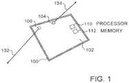
- FIG. 1is a schematic illustration of a mobile device 100 which may be configured to operate in accordance with an embodiment of the invention
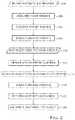
- FIG. 2is a flowchart of acts performed in estimating a distance to an object, in accordance with an embodiment of the invention
- FIG. 3is a schematic illustration of the mobile device in a rotated orientation relative to the orientation of FIG. 1 , in accordance with an embodiment of the invention.
- FIG. 4is a schematic diagram of a calculation of the distance to an object based on images acquired from two different positions, in accordance with an embodiment of the invention.
- An aspect of some embodiments of the inventionrelates to a method of measuring a distance to an object by a mobile device including at least two cameras. At least two images including the object are acquired from respective different positions of the device. Substantially concurrently with acquiring the images including the object (referred to herein as “object images”), respective reference images are acquired by a different camera than the camera acquiring the respective object image. The reference images are used to determine the relative positions of the camera(s) when the at least two images of the object were acquired and using the at least two images and the relative positions of the cameras, the distance to the object is determined.
- the different positions of the cameras acquiring the imagesare achieved by rotating the device and positioning the camera acquiring the reference images such that the reference images are substantially identical.
- the relative position of the camera acquiring the object imagescan then be determined from the extent of rotation and the positions of the cameras on the device.
- the different positions of the cameras acquiring the imagesare achieved by changing the distance between the device and a user holding the device.
- the distances to the user holding the deviceis determined from the reference images.
- device positionis used herein to relate to both the location and orientation of the device, such that two different orientations of the device, even if the device is in the same location, are referred to herein as two different positions.
- the object imagesare all acquired by a first camera and the reference images are all acquired by a second camera. In other embodiments, however, a same camera of the device is used for one or more of the object images and one or more of the reference images.
- FIG. 1is a schematic illustration of a mobile device 100 which may be configured to operate in accordance with an embodiment of the invention.
- Device 100optionally comprises a touch screen 102 , a front camera 104 , having an imaging axis 134 , on the same side as the touch screen 102 and a rear camera 106 , having an imaging axis 132 , directed in an opposite direction from front camera 104 .
- a processor 110 and a memory 112are embedded within mobile device 100 .
- Processor 110is configured with software to carry out distance estimation based on images acquired by front camera 104 and rear camera 106 as described herein below.
- Device 100optionally comprises a smart-phone or tablet, although other devices having the elements discussed herein may also be used.
- processor 110is configured to perform various tasks other than distance estimation, such as encoding and decoding speech signals, and/or any other tasks known to be performed by mobile devices.
- the softwaremay be downloaded to processor 110 in electronic form, over a network, for example, and stored in memory 112 .
- the softwaremay be held on tangible, non-transitory storage media, such as optical, magnetic, or electronic memory media.
- at least some of the functions of processor 110may be performed by dedicated or programmable hardware logic circuits.
- FIG. 2is a flowchart of acts performed in estimating a distance to an object, in accordance with an embodiment of the invention.
- rear camera 106is aimed at the object and mobile device 100 optionally begins to execute a software process that manages a distance estimation procedure.
- mobile device 100acquires ( 206 ) one or more images through rear camera 106 , which is aimed at the object, and in addition acquires ( 208 ) one or more images through front camera 104 .
- a single image pairreferred to herein as (Rear1, Front1), is selected ( 210 ) to represent the rear camera and front camera images.
- Mobile device 100then optionally instructs ( 212 ) the user to change the position or pose of mobile device 100 to a new position and aim front camera 104 in the same direction as before the change in position.
- Mobile device 100optionally verifies ( 214 ) that front camera 104 is properly aimed and then acquires ( 216 ) one or more images by both the front and rear cameras.
- Mobile device 100optionally selects ( 218 ) a single image acquired from the new position for each of the front and rear cameras. The selected pair of images from after the position change is referred to herein as (Rear2, Front2).
- Mobile device 100analyzes the selected images acquired before (Rear1, Front1) and after (Rear2, Front2) the position change, to determine ( 222 ) the change in position of the rear camera 106 due to the change in the position of mobile device 100 . Based on the determined change in the position in the rear camera and the selected images of the object (Rear1 and Rear2) from before and after the change, the distance to the object is estimated ( 224 ), as detailed hereinbelow.
- the instructions ( 212 ) to the user to change the position or pose of device 100include a display of a current video stream acquired by front camera 104 , allowing the user to adjust the position of front camera 104 according to the images it is currently acquiring.
- the instructions ( 212 ) to the userfurther include the selected ( 210 ) image acquired by front camera 104 before the position change (Front1), so the user can easily match the current position of front camera 104 to the selected ( 210 ) previously acquired image Front1.
- the current video streamis overlaid on the displayed image Front1 to allow simple alignment by the user.
- the current video streammay be displayed side by side with image Front1, possibly with a suitable grid correlating between the images.
- a shadow or grid extracted from the Front1 imageis displayed, and the user is requested to match the current video stream to the displayed shadow or grid.
- processor 110compares the images of an image stream currently collected by front camera 104 and the selected Front1 image, for example using feature matching, and accordingly provides aiming instructions, for example in the form of displayed arrows and/or other graphical guidance or spoken directions.
- the feature matchingoptionally includes selecting a feature appearing in both Front1 and the images of the currently collected image stream and determining the relative positions of the features in Front1 and the image stream.
- processor 110calculates a numerical matching extent score and displays the calculated matching extent score to the user.
- processor 110provides a stop instruction when the matching extent is above a predetermined threshold.
- the thresholdmay be a preconfigured threshold used universally, or may be a dynamically adjustable threshold according to a required accuracy level of the distance determination.
- a relatively low thresholdis required and processor 110 digitally compensates for the mismatch by performing image rectification, as described hereinbelow.
- the instructions ( 212 )also request the user to remain still until the images are acquired, in order to minimize the position changes between acquiring (Rear1, Front1) and (Rear2, Front2).
- the estimated distanceis optionally provided to the user by display on screen 102 , sounding to the user or any other suitable method.
- the distancemay be used by processor 110 or provided to a different processor, for further calculations.
- processor 110may optionally determine other sizes and/or distances in the scene, such as the size of the object and/or the distances and sizes of other objects in the images.
- device 100may operate as a measurement tool.
- the distance estimationis used to apply scale-in augmented reality applications, for example in overlaying virtual objects on an image, stream of images or live scene.
- the object sizeis used by processor 110 to improve object tracking between image frames in a video stream acquired by mobile device 100 , for example in surveillance applications.
- the instruction ( 204 ) to estimate a distance to an objectis provided, in some embodiments, by a human user, who is aware of the estimation and participates knowingly in the process. In other embodiments, the instruction ( 204 ) to estimate a distance is provided automatically by another software running on device 100 . In these embodiments, the user may participate knowingly in the process or may not be aware of the process. For example, the instruction ( 212 ) to move the device to a new position may be provided among other instructions provided by the other software initiating the distance estimation, such that the user does not necessarily know that the instructions are performed for distance estimation. Alternatively or additionally, the instruction ( 212 ) to change the position of device 100 is provided in an implied manner, without the user necessarily understanding that there was an instruction. For example, an image on screen 102 may be rotated in order to cause the user to instinctively rotate device 100 .
- At least three, at least five or even at least ten imagesare acquired by each of the cameras in each of the acquiring sessions (e.g., before and after the position change).
- the quality of the imagesare assessed as they are acquired and the image acquiring is repeated until an image, a predetermined number of images or pairs of front and rear images considered to have a sufficient quality, are acquired. Accordingly, in these embodiments, the number of acquired images varies according to the quality of the acquired images. Optionally, the same number of images is acquired by the front and rear cameras.
- front camera 104may be instructed to acquire more images than rear camera 106 .
- the front and rear camera images of each pairare acquired simultaneously or within a very short time difference, such as within less than 5 seconds, less than 1 second, less than a half a second, possibly even less than 30 milliseconds.
- the same criterionis used in determining the number of images acquired before and after the position change of device 100 .
- imagesare acquired until a predetermined number of images of sufficient quality were acquired.
- the same number of imagesis acquired before and after the position change.
- more imagesare acquired before the position change or after the position change.
- the quality assessment after the position changeincludes in addition to an objective quality, or instead of an objective quality, a matching measure indicative of the extent to which the image matches the images acquired before the position change.
- the image selection ( 210 ) of (Rear1, Front1)is performed based on quality assessment methods, such as verifying that the image has strong gradients and/or that the camera did not move while acquiring the picture (e.g., based on accelerometer measurements and/or image analysis).
- the selectionincludes selecting Rear1 as the best quality image acquired before the position change by rear camera 106 , and selecting the corresponding front camera image acquired at the same time to be Front1.
- After selecting Rear1, Front1is selected among a limited number of images acquired within a short period of time before, in parallel to and/or after acquiring Rear1.
- the selection of Rear1 and Front1is based on a weighted score giving different weight to the quality of the rear image and to the quality of the front image.
- the time difference between acquiring each pair of imagesis also factored into the score.
- the selectionprovides a combination of two or more images, for example generated as a weighted sum of the images or of those images considered having a quality above a given threshold.
- low quality imagese.g., blurred images
- the weighted selected imagesare calculated only based on the images considered of sufficient quality.
- the image selection ( 218 ) of (Rear2, Front2)may be performed in a manner similar to the selection ( 210 ) of (Rear1, Front1).
- Front2is selected as the first image considered sufficiently aligned to Front1, which has a sufficient quality.
- processor 110determines the location of the user relative to the background in the Front1 selected image, and analyzes the images acquired after the position change based on the extent to which the location of the user relative to the background in these images, matches the relative location in Front1.
- the image acquired after the position change, which best matches Front1is selected.
- analyzed images having a difference in location beyond a predetermined valueare weeded out from consideration.
- the extent to which the relative location of the user in the analyzed images matches that in Front1is weighted into a quality score used in selecting Front2.
- the useris requested to repeat the acquiring ( 216 ) of images after the position change or is requested to repeat the entire procedure of FIG. 2 .
- processor 110also verifies that the axis of the camera as determined from the rear camera images and/or front camera images did not change substantially between the acquiring of images before and after the position change. Alternatively or additionally, rectification is performed to compensate for movement of the camera axis, as detailed hereinbelow.
- the estimation ( 224 )optionally includes image rectification to correct for rotation bias of the images acquired before and after the position change of rear camera 106 (Rear1, Rear2).
- Rear1 and Rear2are adjusted such that they are both in the same plane.
- the rectificationis performed using any suitable method known in the art, such as any of the methods described in US patent publication 2013/0271578, to Richards, US patent publication 2005/0180632 to Aradhye et al. and Lim, Ser-Nam; Mittal, Anurag; Davis. Larry; Paragios, Nikos., “Uncalibrated stereo rectification for automatic 3d surveillance”. International Conference on Image Processing 2: 1357-1360, 2004, the disclosures of all of which are incorporated herein by reference in their entirety.
- Processor 110then optionally performs a triangulation method on the rectified versions of Rear1 and Rear2 to determine the distance to one or more points of interest in the images.
- the triangulationis performed using any suitable method known in the art, for example, using any of the methods described in Richard Hartley and Andrew Zisserman (2003). Multiple View Geometry in computer vision . Cambridge University Press, the disclosure of which is incorporated herein by reference.
- the triangulationis optionally based on the distance between the positions of the rear camera 106 , before and after the position change, i.e., the positions of rear camera 106 at the time of acquiring Rear1 and Rear2, respectively, and the f-number, also referred to as focal ratio, of rear camera 106 .
- estimation ( 224 )includes creating a stereo or disparity image based on the Rear1, Rear2 images.
- FIG. 3is a schematic illustration of mobile device 100 in a rotated orientation relative to the orientation of FIG. 1 , in accordance with an embodiment of the invention.
- the change in position of mobile device 100is a rotation of the mobile device.
- the instruction ( 212 ) to move mobile device 100 to the new positionincludes in these embodiments, an instruction to rotate the mobile device.
- the useris instructed to position mobile device 100 such that the images acquired by front camera 104 in the new position, after the rotation, are the same as the images acquired before the rotation, adjusted for the extent of rotation of the mobile device 100 .
- the useris instructed to rotate mobile device 100 by 180 degrees, to achieve a maximal change in the position of rear camera 106 relative to front camera 104 .
- the useris instructed to rotate mobile device 100 by 90 degrees, or any other desired extent.
- the usermay be requested to rotate device 100 to an extent close to 180 degrees, for example between 160-200 degrees, thus allowing the user to perform the rotation quickly without accurately adjusting the rotation to 180 degrees.
- FIG. 3which shows device 100 rotated by 180 degrees relative to its position in FIG. 1
- the distance 332 between the imaging axis of rear camera 106 before 334 and after 336 the rotationis twice the distance 140 between the locations of front camera 104 and rear camera 106 , as front camera 104 remains in the same relative location before and after the rotation.
- the determination ( 222 ) of the change in position of rear camera 106is optionally based on the known positions of cameras 104 and 106 on device 100 .
- the determinationincludes estimation of the extent of rotation of mobile device 100 , for example based on a comparison of the images taken by front camera 104 before and after the rotation.
- the estimationis based on a comparison of the images taken by rear camera 106 before and after the rotation.
- the extent of the rotationis known from an angle measurement unit within device 100 .
- front camera 104is directed to the user before and after the rotation
- front camera 104is directed at the object whose distance is to be determined before the rotation and is directed at the user after the rotation. This rotation is referred to herein as flipping.
- an image 352 taken by rear camera 106 before the position changeis optionally displayed to the user, and the user is requested to match images 354 currently acquired by front camera 104 with the displayed image.
- the distanceis optionally calculated based on an analysis of an image acquired by front camera 104 before the position change and an image acquired by rear camera 106 acquired after the position change.
- device 100has screens on both sides, in which the instructions to the user are provided as appropriate on the screen facing the user.
- the instruction ( 212 ) to move mobile device 100 to the new positionincludes an instruction to change the distance between the mobile device and the user (e.g., the user's face), by moving the device closer to the user or farther from the user.
- FIG. 4is a schematic illustration of distance measurement to an object 402 , in accordance with an embodiment of the invention.
- front camera 104acquires an image including a specific body portion (e.g., 410 ).
- the instruction ( 212 ) to the useroptionally states that the image acquired by front camera 104 should include the body portion 410 , and possibly includes an instruction to keep the body portion 410 in a central portion of the image.
- the useris instructed to aim the camera such that the body portion is located in the same relative location within the image acquired after the position change, as before the position change.
- the body portionoptionally includes the human cornea, although other body organs having a nearly fixed size for different people may be used.
- a plurality of different body portionsmay be considered and the distance is determined based on a weighted sum of the distance calculated for each body portion.
- processor 110is configured with the size of the body portion in an initialization stage and thereafter the configured size is used in a plurality of subsequent distance measurements performed by the user.
- the configured sizemay be entered manually by the user, based on a measurement performed without use of device 100 , or may be performed using device 100 , for example in a configuration procedure including acquiring images of the body portion from one or more predetermined distances and/or acquiring a plurality of images from different distances with known relative locations.
- front camera 104is aimed at an object having a known size, such as a ruler, coin or money note.
- a known sizesuch as a ruler, coin or money note.
- the known-size objectis included in the images acquired before and after the position change.
- the known-size objectis placed by the user next to the body portion, so that the size of the body portion can be determined from the known-size object.
- the known-size objectmay appear in only some of the images acquired.
- the change in positionis optionally determined ( 222 ) in these embodiments, based on a comparison of the size of the imaged body portion 410 in the front images before and after the position change (Front1, Front2).
- processor 110counts the number of pixels over which the cornea (or other specific body organ) spans in image Front1 and according to the known width of the cornea and the field of view (iFov) of front camera 104 , calculates the distance (F1) between device 100 and the user at the time the image Front1 was acquired.
- the width of the corneais evaluated as the white to white corneal diameter.
- Processor 110optionally additionally determines the size ratio of the cornea and/or other body portions between Front1 and Front2, referred to herein as FrontZoom and the size ratio of one or more features between Rear1 and Rear2, referred to herein as RearZoom.
- the one or more features used in calculating RearZoomare optionally selected using known methods of feature detection, matching and/or tracking, such as optical flow, speeded up robust features (SURF) and/or scale invariant feature transform (SIFT).
- SURFspeeded up robust features
- SIFTscale invariant feature transform
- R 1F 1*(FrontZoom ⁇ 1)/(1 ⁇ RearZoom)
- the calculationincludes determining the new distance (F2) between user 408 and device 100 , after the position change, in a manner similar to the calculation of F1, F2 may then be used to calculate FrontZoom and/or R2.
- Device 100 in some of the above embodimentsis assumed to be rigid, at least in portions on which cameras 104 and 106 are mounted, such that the relative positions of the cameras does not change.
- device 100may be flexible and/or cameras 104 and/or 106 are movably mounted on device 100 , such that the relative positions of the cameras on device 100 may change.
- processor 110is optionally configured to receive information on the pose of device 100 , which pose information includes not only the location and orientation of device 100 , but also the relative locations of cameras 104 and 106 on device 100 .
- device 100is assumed to be held by a user and the instructions as to changing the position of the device are provided to the user.
- device 100is mounted on a tripod, arm or other mount which includes a motor or other device which controls its movement.
- the mountis configured to receive movement instructions directly from device 100 , such that the entire method of FIG. 2 is carried out automatically without human aid.
- Such a setupmay be used, for example, for surveillance purposes.
Landscapes
- Engineering & Computer Science (AREA)
- Physics & Mathematics (AREA)
- General Physics & Mathematics (AREA)
- Theoretical Computer Science (AREA)
- Multimedia (AREA)
- Remote Sensing (AREA)
- Radar, Positioning & Navigation (AREA)
- Electromagnetism (AREA)
- Computer Vision & Pattern Recognition (AREA)
- Signal Processing (AREA)
- Human Computer Interaction (AREA)
- Optics & Photonics (AREA)
- Health & Medical Sciences (AREA)
- General Health & Medical Sciences (AREA)
- Vascular Medicine (AREA)
- Image Analysis (AREA)
- Geometry (AREA)
- Studio Devices (AREA)
- Length Measuring Devices By Optical Means (AREA)
- Image Processing (AREA)
Abstract
Description
F1=SizeOfCorneaInMeters/(iFovInRadiansToPixel*SizeOfCorneaInPixels)
R1=F1*(FrontZoom−1)/(1−RearZoom)
Claims (20)
Priority Applications (4)
| Application Number | Priority Date | Filing Date | Title |
|---|---|---|---|
| US16/591,292US10691967B2 (en) | 2013-04-08 | 2019-10-02 | Distance estimation using multi-camera device |
| US16/879,000US11879750B2 (en) | 2013-04-08 | 2020-05-20 | Distance estimation using multi-camera device |
| US18/373,685US12209883B2 (en) | 2013-04-08 | 2023-09-27 | Distance estimation using multi-camera device |
| US18/979,228US20250130042A1 (en) | 2013-04-08 | 2024-12-12 | Distance estimation using multi-camera device |
Applications Claiming Priority (6)
| Application Number | Priority Date | Filing Date | Title |
|---|---|---|---|
| US201361809464P | 2013-04-08 | 2013-04-08 | |
| US201361809447P | 2013-04-08 | 2013-04-08 | |
| PCT/IB2014/060462WO2014167475A1 (en) | 2013-04-08 | 2014-04-06 | Distance estimation using multi-camera device |
| US201514783119A | 2015-10-08 | 2015-10-08 | |
| US16/219,519US10467492B2 (en) | 2013-04-08 | 2018-12-13 | Distance estimation using multi-camera device |
| US16/591,292US10691967B2 (en) | 2013-04-08 | 2019-10-02 | Distance estimation using multi-camera device |
Related Parent Applications (1)
| Application Number | Title | Priority Date | Filing Date |
|---|---|---|---|
| US16/219,519ContinuationUS10467492B2 (en) | 2013-04-08 | 2018-12-13 | Distance estimation using multi-camera device |
Related Child Applications (1)
| Application Number | Title | Priority Date | Filing Date |
|---|---|---|---|
| US16/879,000ContinuationUS11879750B2 (en) | 2013-04-08 | 2020-05-20 | Distance estimation using multi-camera device |
Publications (2)
| Publication Number | Publication Date |
|---|---|
| US20200042815A1 US20200042815A1 (en) | 2020-02-06 |
| US10691967B2true US10691967B2 (en) | 2020-06-23 |
Family
ID=51689011
Family Applications (6)
| Application Number | Title | Priority Date | Filing Date |
|---|---|---|---|
| US14/783,119Active2035-05-04US10192312B2 (en) | 2013-04-08 | 2014-04-06 | Distance estimation using multi-camera device |
| US16/219,519ActiveUS10467492B2 (en) | 2013-04-08 | 2018-12-13 | Distance estimation using multi-camera device |
| US16/591,292ActiveUS10691967B2 (en) | 2013-04-08 | 2019-10-02 | Distance estimation using multi-camera device |
| US16/879,000ActiveUS11879750B2 (en) | 2013-04-08 | 2020-05-20 | Distance estimation using multi-camera device |
| US18/373,685ActiveUS12209883B2 (en) | 2013-04-08 | 2023-09-27 | Distance estimation using multi-camera device |
| US18/979,228PendingUS20250130042A1 (en) | 2013-04-08 | 2024-12-12 | Distance estimation using multi-camera device |
Family Applications Before (2)
| Application Number | Title | Priority Date | Filing Date |
|---|---|---|---|
| US14/783,119Active2035-05-04US10192312B2 (en) | 2013-04-08 | 2014-04-06 | Distance estimation using multi-camera device |
| US16/219,519ActiveUS10467492B2 (en) | 2013-04-08 | 2018-12-13 | Distance estimation using multi-camera device |
Family Applications After (3)
| Application Number | Title | Priority Date | Filing Date |
|---|---|---|---|
| US16/879,000ActiveUS11879750B2 (en) | 2013-04-08 | 2020-05-20 | Distance estimation using multi-camera device |
| US18/373,685ActiveUS12209883B2 (en) | 2013-04-08 | 2023-09-27 | Distance estimation using multi-camera device |
| US18/979,228PendingUS20250130042A1 (en) | 2013-04-08 | 2024-12-12 | Distance estimation using multi-camera device |
Country Status (5)
| Country | Link |
|---|---|
| US (6) | US10192312B2 (en) |
| EP (2) | EP2984448B1 (en) |
| KR (10) | KR102210054B1 (en) |
| CN (2) | CN105339756B (en) |
| WO (1) | WO2014167475A1 (en) |
Cited By (3)
| Publication number | Priority date | Publication date | Assignee | Title |
|---|---|---|---|---|
| US12209883B2 (en) | 2013-04-08 | 2025-01-28 | Snap Inc. | Distance estimation using multi-camera device |
| US12301941B2 (en) | 2023-05-23 | 2025-05-13 | Snap Inc. | Recommending relevant content augmentations based on context |
| US12341738B2 (en) | 2022-06-02 | 2025-06-24 | Snap Inc. | Contextual reply augmentation system |
Families Citing this family (7)
| Publication number | Priority date | Publication date | Assignee | Title |
|---|---|---|---|---|
| WO2016025962A1 (en)* | 2014-08-15 | 2016-02-18 | The University Of Akron | Device and method for three-dimensional video communication |
| WO2016086379A1 (en) | 2014-12-04 | 2016-06-09 | SZ DJI Technology Co., Ltd. | Imaging system and method |
| CN110658918B (en)* | 2019-09-25 | 2023-12-12 | 京东方科技集团股份有限公司 | Positioning method, device and medium for eyeball tracking camera of video glasses |
| CN111207688B (en)* | 2020-01-16 | 2022-06-03 | 睿镞科技(北京)有限责任公司 | Method, device and vehicle for measuring distance to target object in a vehicle |
| CN112378507B (en)* | 2020-11-05 | 2021-10-01 | 浙江大学 | A computer vision-based structural vibration monitoring method based on motion compensation |
| KR20230116565A (en)* | 2022-01-28 | 2023-08-04 | 삼성전자주식회사 | Electronic device and controlling method thereof |
| US12277632B2 (en) | 2022-04-26 | 2025-04-15 | Snap Inc. | Augmented reality experiences with dual cameras |
Citations (45)
| Publication number | Priority date | Publication date | Assignee | Title |
|---|---|---|---|---|
| US6038295A (en) | 1996-06-17 | 2000-03-14 | Siemens Aktiengesellschaft | Apparatus and method for recording, communicating and administering digital images |
| DE10334213A1 (en) | 2002-12-06 | 2004-07-15 | Lg Electronics Inc. | Device for controlling the drive of a linear motor and method therefor |
| US20050270368A1 (en) | 2004-06-04 | 2005-12-08 | Electronic Arts Inc. | Motion sensor using dual camera inputs |
| US6980909B2 (en) | 2000-07-24 | 2005-12-27 | Weatherbank, Inc. | Interactive advisory system |
| US20070019000A1 (en) | 2004-06-04 | 2007-01-25 | Hideto Motomura | Display control device, display control method, program, and portable apparatus |
| US7173651B1 (en) | 1998-06-02 | 2007-02-06 | Knowles Andrew T | Apparatus and system for prompt digital photo delivery and archival |
| US20080137940A1 (en) | 2005-02-23 | 2008-06-12 | Aisin Seiki Kabushiki Kaisha | Object Recognition Apparatus and Object Recognition Method Using Epipolar Geometry |
| US7411493B2 (en) | 2003-03-01 | 2008-08-12 | User-Centric Ip, L.P. | User-centric event reporting |
| US7535890B2 (en) | 2003-12-18 | 2009-05-19 | Ayalogic, Inc. | System and method for instant VoIP messaging |
| US20100074609A1 (en) | 2008-09-24 | 2010-03-25 | Fujitsu Limited | Distance measuring device and distance measuring method |
| US20100157128A1 (en) | 2008-12-24 | 2010-06-24 | Samsung Digital Imaging Co., Ltd. | Apparatus and method for capturing image |
| WO2010149854A1 (en) | 2009-06-26 | 2010-12-29 | Valtion Teknillinen Tutkimuskeskus | Method and device for determination of distance |
| US20110025829A1 (en) | 2009-07-31 | 2011-02-03 | 3Dmedia Corporation | Methods, systems, and computer-readable storage media for selecting image capture positions to generate three-dimensional (3d) images |
| US20110141227A1 (en) | 2009-12-11 | 2011-06-16 | Petronel Bigioi | Stereoscopic (3d) panorama creation on handheld device |
| US20110202598A1 (en) | 2010-02-16 | 2011-08-18 | Jeffrey Evans | Messaging System Apparatuses Circuits and Methods of Operation Thereof |
| US20110255775A1 (en) | 2009-07-31 | 2011-10-20 | 3Dmedia Corporation | Methods, systems, and computer-readable storage media for generating three-dimensional (3d) images of a scene |
| US20110304711A1 (en) | 2010-06-14 | 2011-12-15 | Hal Laboratory, Inc. | Storage medium having stored therein stereoscopic image display program, stereoscopic image display device, stereoscopic image display system, and stereoscopic image display method |
| US20120002019A1 (en) | 2010-06-30 | 2012-01-05 | Takashi Hashimoto | Multiple viewpoint imaging control device, multiple viewpoint imaging control method and conputer readable medium |
| US8131597B2 (en) | 1995-06-20 | 2012-03-06 | Neomedia Technologies, Inc. | System and method for using an ordinary article of commerce to access a remote computer |
| US20120147139A1 (en) | 2010-03-19 | 2012-06-14 | Bo Li | Stereoscopic image aligning apparatus, stereoscopic image aligning method, and program of the same |
| CN102550015A (en) | 2010-06-30 | 2012-07-04 | 富士胶片株式会社 | Multi-viewpoint imaging control device, multi-viewpoint imaging control method and multi-viewpoint imaging control program |
| US8259161B1 (en) | 2012-02-06 | 2012-09-04 | Google Inc. | Method and system for automatic 3-D image creation |
| US20120224032A1 (en)* | 2011-02-09 | 2012-09-06 | Sony Corporation | Image capturing device, image capturing device control method, and program |
| US20120242794A1 (en) | 2011-03-24 | 2012-09-27 | Minwoo Park | Producing 3d images from captured 2d video |
| US20120287243A1 (en) | 2011-05-13 | 2012-11-15 | Kenneth Alan Parulski | Stereoscopic camera using anaglyphic display during capture |
| US8332475B2 (en) | 2005-08-22 | 2012-12-11 | Triplay Communications Ltd. | Messaging system and method |
| US20120314036A1 (en) | 2010-12-27 | 2012-12-13 | 3Dmedia Corporation | Primary and auxiliary image capture devcies for image processing and related methods |
| KR20130022831A (en) | 2011-08-26 | 2013-03-07 | 유민규 | Method for measuring distance, height, length using mobile communication terminal |
| CN103017730A (en) | 2012-11-30 | 2013-04-03 | 中兴通讯股份有限公司 | Single-camera ranging method and single-camera ranging system |
| CN202940864U (en) | 2012-11-14 | 2013-05-15 | 吴昊 | Mobile phone with replaceable camera |
| US20130229529A1 (en) | 2010-07-18 | 2013-09-05 | Peter Lablans | Camera to Track an Object |
| US20140029837A1 (en) | 2012-07-30 | 2014-01-30 | Qualcomm Incorporated | Inertial sensor aided instant autofocus |
| US8718333B2 (en) | 2007-04-23 | 2014-05-06 | Ramot At Tel Aviv University Ltd. | System, method and a computer readable medium for providing an output image |
| US20140226864A1 (en) | 2013-02-14 | 2014-08-14 | Qualcomm Incorporated | Camera Aided Motion Direction and Speed Estimation |
| US20140240471A1 (en) | 2013-02-28 | 2014-08-28 | Samsung Electronics Co., Ltd | Method, device and apparatus for generating stereoscopic images using a non-stereoscopic camera |
| US20140285637A1 (en) | 2013-03-20 | 2014-09-25 | Mediatek Inc. | 3d image capture method with 3d preview of preview images generated by monocular camera and related electronic device thereof |
| US20140300722A1 (en)* | 2011-10-19 | 2014-10-09 | The Regents Of The University Of California | Image-based measurement tools |
| US20150002633A1 (en) | 2012-03-13 | 2015-01-01 | Fujifilm Corporation | Imaging apparatus having projector and control method thereof |
| US8937646B1 (en) | 2011-10-05 | 2015-01-20 | Amazon Technologies, Inc. | Stereo imaging using disparate imaging devices |
| US20150124059A1 (en) | 2012-06-08 | 2015-05-07 | Nokia Corporation | Multi-frame image calibrator |
| US9040574B2 (en) | 2001-12-13 | 2015-05-26 | Natrogen Therapeutics International, Inc. | Method of treating androgen independent prostate cancer |
| CA2887596A1 (en) | 2014-01-03 | 2015-07-31 | Benoit LALIBERTE | User content sharing system and method with automated external content integration |
| US20150285631A1 (en) | 2013-03-13 | 2015-10-08 | Panasonic Intellectual Property Management Co., Ltd. | Distance measuring apparatus, imaging apparatus, and distance measuring method |
| US9223404B1 (en) | 2012-01-27 | 2015-12-29 | Amazon Technologies, Inc. | Separating foreground and background objects in captured images |
| CN105339756A (en) | 2013-04-08 | 2016-02-17 | 希玛吉恩媒体有限公司 | Distance evaluation using multiple camera devices |
Family Cites Families (33)
| Publication number | Priority date | Publication date | Assignee | Title |
|---|---|---|---|---|
| AU704947B2 (en)* | 1993-05-18 | 1999-05-06 | University Of Utah Research Foundation | Apparatus and methods for multianalyte homogeneous fluoroimmunoassays |
| DE69526977T2 (en)* | 1994-10-28 | 2003-01-23 | Lasersight Technologies, Inc. | MULTI-CAMERA DEVICE FOR EXAMINATION OF THE CORNEA |
| JP3255360B2 (en)* | 1999-09-22 | 2002-02-12 | 富士重工業株式会社 | Inspection method of distance data and its inspection device |
| US7738706B2 (en) | 2000-09-22 | 2010-06-15 | Sri International | Method and apparatus for recognition of symbols in images of three-dimensional scenes |
| JP4767403B2 (en)* | 2000-11-06 | 2011-09-07 | 本田技研工業株式会社 | Three-dimensional measuring apparatus and three-dimensional measuring method |
| US20050206874A1 (en)* | 2004-03-19 | 2005-09-22 | Dougherty Robert P | Apparatus and method for determining the range of remote point light sources |
| JP2006113807A (en)* | 2004-10-14 | 2006-04-27 | Canon Inc | Multi-viewpoint image processing apparatus and image processing program |
| JP2007258989A (en)* | 2006-03-22 | 2007-10-04 | Eastman Kodak Co | Digital camera, composition corrector, and composition correcting method |
| CN100588902C (en)* | 2006-12-19 | 2010-02-10 | 北京中星微电子有限公司 | Method and device for detecting vehicle distance |
| JP4986679B2 (en) | 2007-03-29 | 2012-07-25 | 学校法人福岡工業大学 | Non-stationary object three-dimensional image measurement apparatus, three-dimensional image measurement method, and three-dimensional image measurement program |
| KR101477182B1 (en)* | 2007-06-01 | 2014-12-29 | 삼성전자주식회사 | Terminal and method of shooting an image thereof |
| US7826736B2 (en)* | 2007-07-06 | 2010-11-02 | Flir Systems Ab | Camera and method for use with camera |
| KR100998709B1 (en)* | 2008-04-28 | 2010-12-07 | 한양대학교 산학협력단 | A method of robot localization using spatial semantics of objects |
| US8204299B2 (en)* | 2008-06-12 | 2012-06-19 | Microsoft Corporation | 3D content aggregation built into devices |
| US20100053151A1 (en)* | 2008-09-02 | 2010-03-04 | Samsung Electronics Co., Ltd | In-line mediation for manipulating three-dimensional content on a display device |
| KR101284798B1 (en)* | 2009-12-08 | 2013-07-10 | 한국전자통신연구원 | Apparatus and method for estimating a distance and a position of an object based on an image of a single camera |
| US8687070B2 (en)* | 2009-12-22 | 2014-04-01 | Apple Inc. | Image capture device having tilt and/or perspective correction |
| JP5489897B2 (en)* | 2010-07-22 | 2014-05-14 | パナソニック株式会社 | Stereo distance measuring device and stereo distance measuring method |
| US9946076B2 (en)* | 2010-10-04 | 2018-04-17 | Gerard Dirk Smits | System and method for 3-D projection and enhancements for interactivity |
| CN102589516B (en)* | 2012-03-01 | 2014-05-28 | 长安大学 | Dynamic distance measuring system based on binocular line scan cameras |
| US9019350B2 (en) | 2012-04-12 | 2015-04-28 | Raytheon Company | Stereo rectification method |
| CN102997891B (en)* | 2012-11-16 | 2015-04-29 | 上海光亮光电科技有限公司 | Device and method for measuring scene depth |
| CN102980556B (en)* | 2012-11-29 | 2015-08-12 | 小米科技有限责任公司 | A kind of distance-finding method and device |
| CN103323461B (en) | 2013-06-14 | 2015-05-27 | 上海大学 | On-line detection method for movement of non-contact type wind driven generator blade |
| CN103344213A (en) | 2013-06-28 | 2013-10-09 | 三星电子(中国)研发中心 | Method and device for measuring distance of double-camera |
| CN103342130B (en) | 2013-07-15 | 2016-02-10 | 齐齐哈尔轨道交通装备有限责任公司 | Hand brake, brake equipment and railway truck |
| CN103824318B (en) | 2014-02-13 | 2016-11-23 | 西安交通大学 | A kind of depth perception method of multi-cam array |
| KR102296396B1 (en)* | 2014-07-31 | 2021-09-02 | 삼성전자주식회사 | Apparatus and method for improving accuracy of contactless thermometer module |
| US10704944B2 (en) | 2014-09-14 | 2020-07-07 | Becton, Dickinson And Company | System and method for capturing dose information |
| KR20160133230A (en)* | 2015-05-12 | 2016-11-22 | 엘지전자 주식회사 | Mobile terminal |
| JP2017060008A (en)* | 2015-09-16 | 2017-03-23 | キヤノン株式会社 | Multi-view image encoding apparatus, multi-view image encoding method, and program |
| JP2017086184A (en) | 2015-11-02 | 2017-05-25 | 国立大学法人埼玉大学 | Muscular activity visualization system and muscular activity visualization method |
| KR20170083327A (en)* | 2016-01-08 | 2017-07-18 | 엘지전자 주식회사 | Mobile terminal and method for controlling the same |
- 2014
- 2014-04-06KRKR1020207023225Apatent/KR102210054B1/enactiveActive
- 2014-04-06KRKR1020227045371Apatent/KR102536174B1/enactiveActive
- 2014-04-06KRKR1020227022411Apatent/KR102482186B1/enactiveActive
- 2014-04-06KRKR1020237032236Apatent/KR20230142635A/ennot_activeCeased
- 2014-04-06USUS14/783,119patent/US10192312B2/enactiveActive
- 2014-04-06KRKR1020157031654Apatent/KR102025535B1/enactiveActive
- 2014-04-06EPEP14782545.9Apatent/EP2984448B1/enactiveActive
- 2014-04-06WOPCT/IB2014/060462patent/WO2014167475A1/enactiveApplication Filing
- 2014-04-06KRKR1020217022065Apatent/KR102357800B1/enactiveActive
- 2014-04-06EPEP21152823.7Apatent/EP3828496A1/enactivePending
- 2014-04-06CNCN201480032676.7Apatent/CN105339756B/enactiveActive
- 2014-04-06CNCN201910630729.XApatent/CN110440747B/enactiveActive
- 2014-04-06KRKR1020197027532Apatent/KR102146641B1/enactiveActive
- 2014-04-06KRKR1020217002542Apatent/KR102279380B1/enactiveActive
- 2014-04-06KRKR1020227002988Apatent/KR102416814B1/enactiveActive
- 2014-04-06KRKR1020237017091Apatent/KR102582420B1/enactiveActive
- 2018
- 2018-12-13USUS16/219,519patent/US10467492B2/enactiveActive
- 2019
- 2019-10-02USUS16/591,292patent/US10691967B2/enactiveActive
- 2020
- 2020-05-20USUS16/879,000patent/US11879750B2/enactiveActive
- 2023
- 2023-09-27USUS18/373,685patent/US12209883B2/enactiveActive
- 2024
- 2024-12-12USUS18/979,228patent/US20250130042A1/enactivePending
Patent Citations (67)
| Publication number | Priority date | Publication date | Assignee | Title |
|---|---|---|---|---|
| US8131597B2 (en) | 1995-06-20 | 2012-03-06 | Neomedia Technologies, Inc. | System and method for using an ordinary article of commerce to access a remote computer |
| US6038295A (en) | 1996-06-17 | 2000-03-14 | Siemens Aktiengesellschaft | Apparatus and method for recording, communicating and administering digital images |
| US7173651B1 (en) | 1998-06-02 | 2007-02-06 | Knowles Andrew T | Apparatus and system for prompt digital photo delivery and archival |
| US8909679B2 (en) | 2000-07-24 | 2014-12-09 | Locator Ip, Lp | Interactive advisory system |
| US6980909B2 (en) | 2000-07-24 | 2005-12-27 | Weatherbank, Inc. | Interactive advisory system |
| US9191776B2 (en) | 2000-07-24 | 2015-11-17 | Locator Ip, Lp | Interactive advisory system |
| US9204252B2 (en) | 2000-07-24 | 2015-12-01 | Locator IP, L.P. | Interactive advisory system |
| US9040574B2 (en) | 2001-12-13 | 2015-05-26 | Natrogen Therapeutics International, Inc. | Method of treating androgen independent prostate cancer |
| DE10334213A1 (en) | 2002-12-06 | 2004-07-15 | Lg Electronics Inc. | Device for controlling the drive of a linear motor and method therefor |
| US7411493B2 (en) | 2003-03-01 | 2008-08-12 | User-Centric Ip, L.P. | User-centric event reporting |
| US7535890B2 (en) | 2003-12-18 | 2009-05-19 | Ayalogic, Inc. | System and method for instant VoIP messaging |
| US8995433B2 (en) | 2003-12-18 | 2015-03-31 | Empire Ip Llc | System and method for instant VoIP messaging |
| US8724622B2 (en) | 2003-12-18 | 2014-05-13 | Empire Ip Llc | System and method for instant VoIP messaging |
| US8199747B2 (en) | 2003-12-18 | 2012-06-12 | Ayalogic, Inc. | System and method for instant VoIP messaging |
| CN1934584A (en) | 2004-06-04 | 2007-03-21 | 松下电器产业株式会社 | Display control device, display control method, program, and portable apparatus |
| US20070019000A1 (en) | 2004-06-04 | 2007-01-25 | Hideto Motomura | Display control device, display control method, program, and portable apparatus |
| US20050270368A1 (en) | 2004-06-04 | 2005-12-08 | Electronic Arts Inc. | Motion sensor using dual camera inputs |
| US20080137940A1 (en) | 2005-02-23 | 2008-06-12 | Aisin Seiki Kabushiki Kaisha | Object Recognition Apparatus and Object Recognition Method Using Epipolar Geometry |
| US9491134B2 (en) | 2005-08-22 | 2016-11-08 | Triplay, Inc. | Messaging system and method |
| US8874677B2 (en) | 2005-08-22 | 2014-10-28 | Triplay Communications Ltd. | Messaging system and method |
| US8332475B2 (en) | 2005-08-22 | 2012-12-11 | Triplay Communications Ltd. | Messaging system and method |
| US9100806B2 (en) | 2005-08-22 | 2015-08-04 | Triplay, Inc. | Messaging system and method |
| US9100807B2 (en) | 2005-08-22 | 2015-08-04 | Triplay, Inc. | Messaging system and method |
| US9055416B2 (en) | 2005-08-22 | 2015-06-09 | Triplay, Inc. | Messaging system and method |
| US8718333B2 (en) | 2007-04-23 | 2014-05-06 | Ramot At Tel Aviv University Ltd. | System, method and a computer readable medium for providing an output image |
| US20100074609A1 (en) | 2008-09-24 | 2010-03-25 | Fujitsu Limited | Distance measuring device and distance measuring method |
| US20100157128A1 (en) | 2008-12-24 | 2010-06-24 | Samsung Digital Imaging Co., Ltd. | Apparatus and method for capturing image |
| WO2010149854A1 (en) | 2009-06-26 | 2010-12-29 | Valtion Teknillinen Tutkimuskeskus | Method and device for determination of distance |
| US20110025829A1 (en) | 2009-07-31 | 2011-02-03 | 3Dmedia Corporation | Methods, systems, and computer-readable storage media for selecting image capture positions to generate three-dimensional (3d) images |
| US20110255775A1 (en) | 2009-07-31 | 2011-10-20 | 3Dmedia Corporation | Methods, systems, and computer-readable storage media for generating three-dimensional (3d) images of a scene |
| US20110141227A1 (en) | 2009-12-11 | 2011-06-16 | Petronel Bigioi | Stereoscopic (3d) panorama creation on handheld device |
| US20110202598A1 (en) | 2010-02-16 | 2011-08-18 | Jeffrey Evans | Messaging System Apparatuses Circuits and Methods of Operation Thereof |
| US9489661B2 (en) | 2010-02-16 | 2016-11-08 | Tigertext, Inc. | Messaging system apparatuses circuits and methods of operation thereof |
| US9443227B2 (en) | 2010-02-16 | 2016-09-13 | Tigertext, Inc. | Messaging system apparatuses circuits and methods of operation thereof |
| US20120209924A1 (en) | 2010-02-16 | 2012-08-16 | Jeffrey Evans | Messaging System Apparatuses Circuits and Methods of Operation Thereof |
| US20120147139A1 (en) | 2010-03-19 | 2012-06-14 | Bo Li | Stereoscopic image aligning apparatus, stereoscopic image aligning method, and program of the same |
| US20110304711A1 (en) | 2010-06-14 | 2011-12-15 | Hal Laboratory, Inc. | Storage medium having stored therein stereoscopic image display program, stereoscopic image display device, stereoscopic image display system, and stereoscopic image display method |
| US20120002019A1 (en) | 2010-06-30 | 2012-01-05 | Takashi Hashimoto | Multiple viewpoint imaging control device, multiple viewpoint imaging control method and conputer readable medium |
| CN102550015A (en) | 2010-06-30 | 2012-07-04 | 富士胶片株式会社 | Multi-viewpoint imaging control device, multi-viewpoint imaging control method and multi-viewpoint imaging control program |
| US20130229529A1 (en) | 2010-07-18 | 2013-09-05 | Peter Lablans | Camera to Track an Object |
| US20120314036A1 (en) | 2010-12-27 | 2012-12-13 | 3Dmedia Corporation | Primary and auxiliary image capture devcies for image processing and related methods |
| US20120224032A1 (en)* | 2011-02-09 | 2012-09-06 | Sony Corporation | Image capturing device, image capturing device control method, and program |
| US20120242794A1 (en) | 2011-03-24 | 2012-09-27 | Minwoo Park | Producing 3d images from captured 2d video |
| US20120287243A1 (en) | 2011-05-13 | 2012-11-15 | Kenneth Alan Parulski | Stereoscopic camera using anaglyphic display during capture |
| KR20130022831A (en) | 2011-08-26 | 2013-03-07 | 유민규 | Method for measuring distance, height, length using mobile communication terminal |
| US8937646B1 (en) | 2011-10-05 | 2015-01-20 | Amazon Technologies, Inc. | Stereo imaging using disparate imaging devices |
| US20140300722A1 (en)* | 2011-10-19 | 2014-10-09 | The Regents Of The University Of California | Image-based measurement tools |
| US9223404B1 (en) | 2012-01-27 | 2015-12-29 | Amazon Technologies, Inc. | Separating foreground and background objects in captured images |
| US8259161B1 (en) | 2012-02-06 | 2012-09-04 | Google Inc. | Method and system for automatic 3-D image creation |
| US20130201301A1 (en) | 2012-02-06 | 2013-08-08 | Google Inc. | Method and System for Automatic 3-D Image Creation |
| US20150002633A1 (en) | 2012-03-13 | 2015-01-01 | Fujifilm Corporation | Imaging apparatus having projector and control method thereof |
| US20150124059A1 (en) | 2012-06-08 | 2015-05-07 | Nokia Corporation | Multi-frame image calibrator |
| US20140029837A1 (en) | 2012-07-30 | 2014-01-30 | Qualcomm Incorporated | Inertial sensor aided instant autofocus |
| CN202940864U (en) | 2012-11-14 | 2013-05-15 | 吴昊 | Mobile phone with replaceable camera |
| EP2927634A2 (en) | 2012-11-30 | 2015-10-07 | ZTE Corporation | Single-camera ranging method and system |
| CN103017730A (en) | 2012-11-30 | 2013-04-03 | 中兴通讯股份有限公司 | Single-camera ranging method and single-camera ranging system |
| US20150310619A1 (en) | 2012-11-30 | 2015-10-29 | Zte Corporation | Single-Camera Distance Ranging Method and System |
| US20140226864A1 (en) | 2013-02-14 | 2014-08-14 | Qualcomm Incorporated | Camera Aided Motion Direction and Speed Estimation |
| US20140240471A1 (en) | 2013-02-28 | 2014-08-28 | Samsung Electronics Co., Ltd | Method, device and apparatus for generating stereoscopic images using a non-stereoscopic camera |
| US20150285631A1 (en) | 2013-03-13 | 2015-10-08 | Panasonic Intellectual Property Management Co., Ltd. | Distance measuring apparatus, imaging apparatus, and distance measuring method |
| US20140285637A1 (en) | 2013-03-20 | 2014-09-25 | Mediatek Inc. | 3d image capture method with 3d preview of preview images generated by monocular camera and related electronic device thereof |
| US20160048968A1 (en) | 2013-04-08 | 2016-02-18 | Cimagine Media Ltd | Distance Estimation Using Multi-Camera Device |
| CN105339756A (en) | 2013-04-08 | 2016-02-17 | 希玛吉恩媒体有限公司 | Distance evaluation using multiple camera devices |
| US10192312B2 (en) | 2013-04-08 | 2019-01-29 | C3D Augmented Reality Solutions Ltd | Distance estimation using multi-camera device |
| US20190130201A1 (en) | 2013-04-08 | 2019-05-02 | C3D Augmented Reality Solutions Ltd | Distance estimation using multi-camera device |
| US10467492B2 (en) | 2013-04-08 | 2019-11-05 | C3D Augmented Reality Solutions Ltd | Distance estimation using multi-camera device |
| CA2887596A1 (en) | 2014-01-03 | 2015-07-31 | Benoit LALIBERTE | User content sharing system and method with automated external content integration |
Non-Patent Citations (36)
Cited By (3)
| Publication number | Priority date | Publication date | Assignee | Title |
|---|---|---|---|---|
| US12209883B2 (en) | 2013-04-08 | 2025-01-28 | Snap Inc. | Distance estimation using multi-camera device |
| US12341738B2 (en) | 2022-06-02 | 2025-06-24 | Snap Inc. | Contextual reply augmentation system |
| US12301941B2 (en) | 2023-05-23 | 2025-05-13 | Snap Inc. | Recommending relevant content augmentations based on context |
Also Published As
Similar Documents
| Publication | Publication Date | Title |
|---|---|---|
| US12209883B2 (en) | Distance estimation using multi-camera device | |
| CN109960401B (en) | Dynamic projection method, device and system based on face tracking | |
| US10297076B2 (en) | Apparatus and method for generating 3D face model using mobile device | |
| KR102111935B1 (en) | Display control apparatus, display control method, and program | |
| CN107273846B (en) | Human body shape parameter determination method and device | |
| CN108416285A (en) | Rifle ball linkage surveillance method, apparatus and computer readable storage medium | |
| CN104205828A (en) | Method and system for automatic 3D image creation | |
| JP2013171523A (en) | Ar image processing device and method | |
| KR101459522B1 (en) | Location Correction Method Using Additional Information of Mobile Instrument |
Legal Events
| Date | Code | Title | Description |
|---|---|---|---|
| FEPP | Fee payment procedure | Free format text:ENTITY STATUS SET TO UNDISCOUNTED (ORIGINAL EVENT CODE: BIG.); ENTITY STATUS OF PATENT OWNER: LARGE ENTITY | |
| STPP | Information on status: patent application and granting procedure in general | Free format text:NOTICE OF ALLOWANCE MAILED -- APPLICATION RECEIVED IN OFFICE OF PUBLICATIONS | |
| AS | Assignment | Owner name:SNAP INC., CALIFORNIA Free format text:ASSIGNMENT OF ASSIGNORS INTEREST;ASSIGNOR:SNAP GROUP LIMITED (SNAPCHAT LIMITED);REEL/FRAME:052652/0845 Effective date:20200512 Owner name:C3D AUGMENTED REALITY SOLUTIONS LTD, ISRAEL Free format text:ASSIGNMENT OF ASSIGNORS INTEREST;ASSIGNOR:CIMAGINE MEDIA LTD;REEL/FRAME:052652/0706 Effective date:20170115 Owner name:CIMAGINE MEDIA LTD., ISRAEL Free format text:ASSIGNMENT OF ASSIGNORS INTEREST;ASSIGNORS:ZAK, EYAL;EGRI, OZI;REEL/FRAME:052652/0337 Effective date:20151008 Owner name:SNAPCHAT LIMITED, UNITED KINGDOM Free format text:ASSIGNMENT OF ASSIGNORS INTEREST;ASSIGNOR:CIMGAINE MEDIA LTD.;REEL/FRAME:052655/0693 Effective date:20161220 | |
| STPP | Information on status: patent application and granting procedure in general | Free format text:PUBLICATIONS -- ISSUE FEE PAYMENT VERIFIED | |
| STCF | Information on status: patent grant | Free format text:PATENTED CASE | |
| CC | Certificate of correction | ||
| MAFP | Maintenance fee payment | Free format text:PAYMENT OF MAINTENANCE FEE, 4TH YEAR, LARGE ENTITY (ORIGINAL EVENT CODE: M1551); ENTITY STATUS OF PATENT OWNER: LARGE ENTITY Year of fee payment:4 |