US10691332B2 - Text input on an interactive display - Google Patents
Text input on an interactive displayDownload PDFInfo
- Publication number
- US10691332B2 US10691332B2US14/633,673US201514633673AUS10691332B2US 10691332 B2US10691332 B2US 10691332B2US 201514633673 AUS201514633673 AUS 201514633673AUS 10691332 B2US10691332 B2US 10691332B2
- Authority
- US
- United States
- Prior art keywords
- display
- user
- area
- gesture
- particular embodiments
- Prior art date
- Legal status (The legal status is an assumption and is not a legal conclusion. Google has not performed a legal analysis and makes no representation as to the accuracy of the status listed.)
- Active, expires
Links
Images


Classifications
- G—PHYSICS
- G06—COMPUTING OR CALCULATING; COUNTING
- G06F—ELECTRIC DIGITAL DATA PROCESSING
- G06F3/00—Input arrangements for transferring data to be processed into a form capable of being handled by the computer; Output arrangements for transferring data from processing unit to output unit, e.g. interface arrangements
- G06F3/01—Input arrangements or combined input and output arrangements for interaction between user and computer
- G06F3/048—Interaction techniques based on graphical user interfaces [GUI]
- G06F3/0487—Interaction techniques based on graphical user interfaces [GUI] using specific features provided by the input device, e.g. functions controlled by the rotation of a mouse with dual sensing arrangements, or of the nature of the input device, e.g. tap gestures based on pressure sensed by a digitiser
- G06F3/0488—Interaction techniques based on graphical user interfaces [GUI] using specific features provided by the input device, e.g. functions controlled by the rotation of a mouse with dual sensing arrangements, or of the nature of the input device, e.g. tap gestures based on pressure sensed by a digitiser using a touch-screen or digitiser, e.g. input of commands through traced gestures
- G06F3/04886—Interaction techniques based on graphical user interfaces [GUI] using specific features provided by the input device, e.g. functions controlled by the rotation of a mouse with dual sensing arrangements, or of the nature of the input device, e.g. tap gestures based on pressure sensed by a digitiser using a touch-screen or digitiser, e.g. input of commands through traced gestures by partitioning the display area of the touch-screen or the surface of the digitising tablet into independently controllable areas, e.g. virtual keyboards or menus
- G—PHYSICS
- G06—COMPUTING OR CALCULATING; COUNTING
- G06F—ELECTRIC DIGITAL DATA PROCESSING
- G06F1/00—Details not covered by groups G06F3/00 - G06F13/00 and G06F21/00
- G06F1/16—Constructional details or arrangements
- G06F1/1613—Constructional details or arrangements for portable computers
- G06F1/163—Wearable computers, e.g. on a belt
- G—PHYSICS
- G06—COMPUTING OR CALCULATING; COUNTING
- G06F—ELECTRIC DIGITAL DATA PROCESSING
- G06F3/00—Input arrangements for transferring data to be processed into a form capable of being handled by the computer; Output arrangements for transferring data from processing unit to output unit, e.g. interface arrangements
- G06F3/01—Input arrangements or combined input and output arrangements for interaction between user and computer
- G06F3/016—Input arrangements with force or tactile feedback as computer generated output to the user
- G—PHYSICS
- G06—COMPUTING OR CALCULATING; COUNTING
- G06F—ELECTRIC DIGITAL DATA PROCESSING
- G06F3/00—Input arrangements for transferring data to be processed into a form capable of being handled by the computer; Output arrangements for transferring data from processing unit to output unit, e.g. interface arrangements
- G06F3/01—Input arrangements or combined input and output arrangements for interaction between user and computer
- G06F3/017—Gesture based interaction, e.g. based on a set of recognized hand gestures
- G—PHYSICS
- G06—COMPUTING OR CALCULATING; COUNTING
- G06F—ELECTRIC DIGITAL DATA PROCESSING
- G06F3/00—Input arrangements for transferring data to be processed into a form capable of being handled by the computer; Output arrangements for transferring data from processing unit to output unit, e.g. interface arrangements
- G06F3/01—Input arrangements or combined input and output arrangements for interaction between user and computer
- G06F3/02—Input arrangements using manually operated switches, e.g. using keyboards or dials
- G06F3/023—Arrangements for converting discrete items of information into a coded form, e.g. arrangements for interpreting keyboard generated codes as alphanumeric codes, operand codes or instruction codes
- G06F3/0233—Character input methods
- G06F3/0236—Character input methods using selection techniques to select from displayed items
- G—PHYSICS
- G06—COMPUTING OR CALCULATING; COUNTING
- G06F—ELECTRIC DIGITAL DATA PROCESSING
- G06F3/00—Input arrangements for transferring data to be processed into a form capable of being handled by the computer; Output arrangements for transferring data from processing unit to output unit, e.g. interface arrangements
- G06F3/01—Input arrangements or combined input and output arrangements for interaction between user and computer
- G06F3/02—Input arrangements using manually operated switches, e.g. using keyboards or dials
- G06F3/023—Arrangements for converting discrete items of information into a coded form, e.g. arrangements for interpreting keyboard generated codes as alphanumeric codes, operand codes or instruction codes
- G06F3/0233—Character input methods
- G06F3/0237—Character input methods using prediction or retrieval techniques
- G—PHYSICS
- G06—COMPUTING OR CALCULATING; COUNTING
- G06F—ELECTRIC DIGITAL DATA PROCESSING
- G06F3/00—Input arrangements for transferring data to be processed into a form capable of being handled by the computer; Output arrangements for transferring data from processing unit to output unit, e.g. interface arrangements
- G06F3/01—Input arrangements or combined input and output arrangements for interaction between user and computer
- G06F3/03—Arrangements for converting the position or the displacement of a member into a coded form
- G06F3/033—Pointing devices displaced or positioned by the user, e.g. mice, trackballs, pens or joysticks; Accessories therefor
- G06F3/0346—Pointing devices displaced or positioned by the user, e.g. mice, trackballs, pens or joysticks; Accessories therefor with detection of the device orientation or free movement in a 3D space, e.g. 3D mice, 6-DOF [six degrees of freedom] pointers using gyroscopes, accelerometers or tilt-sensors
- G—PHYSICS
- G06—COMPUTING OR CALCULATING; COUNTING
- G06F—ELECTRIC DIGITAL DATA PROCESSING
- G06F3/00—Input arrangements for transferring data to be processed into a form capable of being handled by the computer; Output arrangements for transferring data from processing unit to output unit, e.g. interface arrangements
- G06F3/01—Input arrangements or combined input and output arrangements for interaction between user and computer
- G06F3/048—Interaction techniques based on graphical user interfaces [GUI]
- G06F3/0484—Interaction techniques based on graphical user interfaces [GUI] for the control of specific functions or operations, e.g. selecting or manipulating an object, an image or a displayed text element, setting a parameter value or selecting a range
- G06F3/04842—Selection of displayed objects or displayed text elements
- G—PHYSICS
- G06—COMPUTING OR CALCULATING; COUNTING
- G06F—ELECTRIC DIGITAL DATA PROCESSING
- G06F3/00—Input arrangements for transferring data to be processed into a form capable of being handled by the computer; Output arrangements for transferring data from processing unit to output unit, e.g. interface arrangements
- G06F3/01—Input arrangements or combined input and output arrangements for interaction between user and computer
- G06F3/048—Interaction techniques based on graphical user interfaces [GUI]
- G06F3/0484—Interaction techniques based on graphical user interfaces [GUI] for the control of specific functions or operations, e.g. selecting or manipulating an object, an image or a displayed text element, setting a parameter value or selecting a range
- G06F3/04847—Interaction techniques to control parameter settings, e.g. interaction with sliders or dials
- G—PHYSICS
- G06—COMPUTING OR CALCULATING; COUNTING
- G06F—ELECTRIC DIGITAL DATA PROCESSING
- G06F3/00—Input arrangements for transferring data to be processed into a form capable of being handled by the computer; Output arrangements for transferring data from processing unit to output unit, e.g. interface arrangements
- G06F3/01—Input arrangements or combined input and output arrangements for interaction between user and computer
- G06F3/048—Interaction techniques based on graphical user interfaces [GUI]
- G06F3/0487—Interaction techniques based on graphical user interfaces [GUI] using specific features provided by the input device, e.g. functions controlled by the rotation of a mouse with dual sensing arrangements, or of the nature of the input device, e.g. tap gestures based on pressure sensed by a digitiser
- G06F3/0488—Interaction techniques based on graphical user interfaces [GUI] using specific features provided by the input device, e.g. functions controlled by the rotation of a mouse with dual sensing arrangements, or of the nature of the input device, e.g. tap gestures based on pressure sensed by a digitiser using a touch-screen or digitiser, e.g. input of commands through traced gestures
- G06F3/04883—Interaction techniques based on graphical user interfaces [GUI] using specific features provided by the input device, e.g. functions controlled by the rotation of a mouse with dual sensing arrangements, or of the nature of the input device, e.g. tap gestures based on pressure sensed by a digitiser using a touch-screen or digitiser, e.g. input of commands through traced gestures for inputting data by handwriting, e.g. gesture or text
Definitions
- This disclosuregenerally relates to text input on an interactive display.
- Electronic devicesmay contain a display screen that displays information to a user of the device.
- An electronic devicemay also contain an input screen that receives input from the user. At times the input screen and the display screen may be the same or share the same surface.
- a user of a devicecan provide input to the device through the input screen while viewing content on the display screen. When the two are the same, the user can view content on the display screen while inputting content on the same screen. For example, a user can interact with a button or icon displayed on the display screen, or can input text, such as for example numbers, characters, symbols, or any combination thereof, to an input screen of a device.
- FIG. 1illustrates an example embodiment of an wearable electronic device.
- FIG. 2illustrates an example stack-up of a device.
- FIGS. 3A-3Eillustrate example form factors of a device.
- FIG. 4Aillustrates an example cross-section of a device body.
- FIGS. 4B-Cillustrate example connections between components of a device.
- FIGS. 5A-5Fillustrate example displays of a device.
- FIGS. 6A-Cillustrate example cross-sectional views of a device display.
- FIGS. 7A-7Dillustrate example outer elements about a device body.
- FIGS. 8A-8Cillustrate example outer elements about a device body.
- FIG. 9illustrates an example sealing ring of a device.
- FIG. 10illustrates an example retention ring of a device.
- FIG. 11illustrates various example embodiments for wearing a device.
- FIGS. 12A-12Billustrate a band attached to a body of a device.
- FIGS. 13A-13Iillustrate example embodiments for fastening or affixing a band of a device.
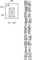
- FIGS. 14A-Dillustrate example camera placements on a device.
- FIG. 15illustrates an example device with a band and optical sensor.
- FIG. 16illustrates an example viewing triangle including a user, a device, and an object.
- FIG. 17illustrates an example angle of view for an optical sensor of a device.
- FIGS. 18A-18Billustrate example optical sensors of a device.
- FIG. 19illustrates an example sensor detection system of a device.
- FIGS. 20A-20Cillustrate example chargers operable with a device.
- FIGS. 21A-21Billustrate example chargers operable with a device.
- FIGS. 22A-22Billustrate example charging units operable with a device.
- FIG. 23illustrates an example charging scheme for a charging unit operable with a device.
- FIG. 24illustrates an example charging scheme for a charging unit operable with a device.
- FIGS. 25A-25Eillustrate example embodiments of energy storage and charging in a device and a charging unit.
- FIG. 26illustrates an example charging unit architecture.
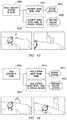
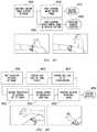
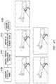
- FIGS. 27-92illustrate example gestures for use with a device.
- FIGS. 93A-93Billustrate example user inputs to a device.
- FIGS. 94A-94Cillustrate example user inputs to a device.
- FIGS. 95A-95Dillustrate example user touch input to a device.
- FIGS. 96A-96Billustrate example graphical user interface models of a device.
- FIG. 97illustrates an example graphical user interface model of a device.
- FIGS. 98A-98Gillustrate example graphical user interface models of a device.
- FIG. 99illustrates an example graphical user interface model of a device.
- FIGS. 100A-100Cillustrate example graphical user interface models of a device.
- FIGS. 101A-101Billustrate example screens of a graphical user interface of a device.
- FIGS. 102A-102Dillustrate example screens of a graphical user interface of a device.
- FIGS. 103A-103Dillustrate example screens of a graphical user interface of a device.
- FIG. 104illustrates an example menu of a graphical user interface of a device.
- FIGS. 105A-105Dillustrate example menus of a graphical user interface of a device.
- FIGS. 106A-106Cillustrate example menus of a graphical user interface of a device.
- FIGS. 107A-107Cillustrate example menus of a graphical user interface of a device.
- FIG. 108illustrates an example menu of a graphical user interface of a device.
- FIGS. 109A-109Cillustrate example menus of a graphical user interface of a device.
- FIGS. 110A-110Billustrate examples of scrolling in a graphical user interface of a device.
- FIG. 111A-111Cillustrate examples of scrolling in a graphical user interface of a device.
- FIG. 112illustrates examples of overlay and background content in a graphical user interface of a device.
- FIGS. 113A-Cillustrate examples of overlay and background content in a graphical user interface of a device.
- FIGS. 114A-114Billustrate example visual transition effects in a graphical user interface of a device.
- FIGS. 115A-115Billustrate example visual transition effects in a graphical user interface of a device.
- FIGS. 116A-116Billustrate example visual transition effects in a graphical user interface of a device.
- FIGS. 117A-117Billustrate example visual transition effects in a graphical user interface of a device.
- FIGS. 118A-118Cillustrate example visual transition effects in a graphical user interface of a device.
- FIGS. 119A-119Cillustrate example visual transition effects in a graphical user interface of a device.
- FIGS. 120A-120Cillustrate example visual transition effects in a graphical user interface of a device.
- FIGS. 121A-121Billustrate example visual transition effects in a graphical user interface of a device.
- FIG. 122illustrates an example use of a physical model in a graphical user interface of a device.
- FIG. 123illustrates example screens of a graphical user interface of a device.
- FIG. 124illustrates example screens of a graphical user interface of a device.
- FIG. 125illustrates an example method for automatic camera activation in a device.
- FIG. 126illustrates an example method for delegation by a device.
- FIG. 127illustrates example delegation models including a device.
- FIG. 128illustrates an example method for delegating by a device.
- FIGS. 129A-129Dillustrate example modes of a device.
- FIG. 130illustrates an example mode of a device.
- FIGS. 131A-131Dillustrate example modes of a device.
- FIG. 132illustrates an example method for providing augmented reality functions on a device.
- FIG. 133illustrates an example network environment in which a device may operate.
- FIG. 134illustrates an example of pairing between a device and a target device.
- FIG. 135illustrates an example method for pairing a device with a target device.
- FIG. 136illustrates example screens of a graphical user interface of a device.
- FIG. 137illustrates an example computer system comprising a device.
- FIGS. 138A-Eillustrate an example device with an example circular display that contains a display portion for inputting text, a portion for displaying inputted text, and a portion for displaying text available for input.
- FIGS. 139A-Fillustrate an example device with an example circular display that contains a display portion for inputting text, a portion for displaying inputted text, and a portion for displaying text available for input.
- FIGS. 140A-Billustrate an example device with an example circular display that contains a display portion for inputting text, a portion for displaying inputted text, and a portion for displaying text available for input, and a portion for suggesting selectable character strings to a user.
- FIGS. 141A-Billustrates an example device having a portion on which a user can input handwritten text.
- FIGS. 142A-Billustrate an example device having a portion on which a user can input guided handwritten text.
- FIGS. 143A-Billustrate an example device having a portion on which a user can input guided handwritten text.
- FIGS. 144A-Billustrate an example device having a portion on which a user can input guided handwritten text.
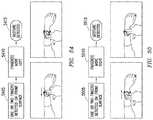
- FIGS. 145A-Billustrate example gestures that can be captured by a sensor of an example device to input text onto the device.
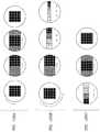
- FIGS. 146A-Cillustrate example character layouts for small displays displaying the English alphabet.
- FIGS. 146D-Eillustrate example highlighting of selected text.
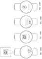
- FIGS. 147A-Cillustrate examples of altering displayed characters available for selection based on previously selected characters.
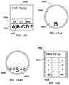
- FIGS. 148A-Cillustrate example layouts for example character sets displayed on the outer edge of an example circular display.
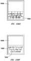
- FIGS. 149A-Cillustrate example layouts for example character sets displayed on an example rectangular display.
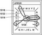
- FIGS. 150A-Dillustrate example hierarchical layouts for presenting characters to input to a display.
- FIGS. 151A-Dillustrate example gestures to select characters to input on example displays.
- FIGS. 152A-Cillustrate example interfaces for inputting text onto a display.
- FIGS. 153A-Billustrate example interfaces for inputting text onto a display.
- FIGS. 154A-Dillustrate example interfaces for inputting text onto a display.
- FIGS. 155A-Dillustrate example interfaces that rearrange characters as a user enters text onto a display.
- FIGS. 156A-Pillustrate example groupings of characters for entry onto a display.
- FIGS. 157A-Dillustrate example groupings of characters for entry onto a display.
- FIGS. 158A-Billustrate example groupings of characters for entry onto a display.
- FIGS. 159A-Fillustrate example displays having example interactive elements for inputting characters onto the display.
- FIG. 160illustrate an example display having example interactive elements for inputting characters and suggested character strings onto the display.
- FIG. 161illustrates an example display having example interactive elements for inputting characters onto the display.
- FIG. 162illustrate an example display having example interactive elements for inputting characters and suggested character strings onto the display.
- FIG. 163illustrate an example display having example interactive elements for inputting characters onto the display.
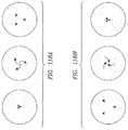
- FIGS. 164A-Billustrate example displays having example interactive elements for inputting characters onto the display.
- FIG. 165illustrates an example interface for constructing characters for input to an example display using example character portions.
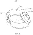
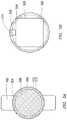
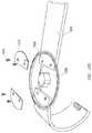
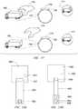
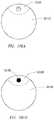
- FIG. 1illustrates an example embodiment of an wearable electronic device 100 .
- Device 100includes a body 105 containing all or some of the circuitry, structure, and display of device 100 .
- body 105may include all or some of the processing components, data storage components, memory, sensors, wiring, or communication components of device 100 .
- device 100may include a display.
- the displaymay take any suitable form or shape, such as for example a circular shape, as illustrated by circular display 110 .
- “circular display”includes substantially circular displays or circular-like displays, such as for example elliptical displays.
- device 100may include an element about the display.
- an element about the displayincludes a rotatable element encircling the display or the body on or in which the display sits.
- an elementmay be an outer ring 115 about a circular display 110 .
- the element about the displaymay move relative to the display or body.
- outer ring 115may rotate relative to the body of device 100 , as described more fully below.
- device 100may include a band 120 attached to body 105 .
- device 100may include a sensor module, such as for example camera module 125 housing a camera, affixed in or to body 105 or band 125 , as described more fully below.
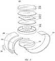
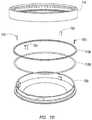
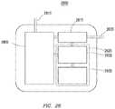
- FIG. 2illustrates an example stack-up 200 of an wearable electronic device. As illustrated in FIG. 2 , some or all of the components of stack-up 200 may adopt the form of the device, which is circular in the example of FIG. 2 .
- Stack-up 200may include a layer of protective glass (or other suitable transparent, solid material) 205 .
- protective glass 205may be laminated to protective glass 205 , or be attached to base 245 .
- protective layer 205may be mechanically connected to outer ring 235 , or any other suitable component of the body of the device.
- Directly beneath protective glass 205may be a touch-sensitive layer 210 .
- Touch-sensitive layer 210may be composed of any suitable material and be of any suitable type, such as for example resistive, surface acoustic wave, capacitive (including mutual capacitive or self-capacitive), infrared, optical, dispersive, or any other suitable type. Touch-sensitive layer 210 may be applied directly to protective glass 205 , laminated onto it, or physically affixed to.
- Touch-sensitive layer 210may be a fully two-dimensional touch surface, or may be composed of touch-sensitive regions, such as a number of capacitive buttons or areas. Touch-sensitive layer 210 may be connected to processor board 215 via a flexible connector at the edge of the touch surface, as described more fully herein
- Display 215may be laminated or mechanically affixed to any of the preceding or forgoing layers. In particular embodiments, lamination may reduce glare and improve display legibility by reducing internal reflections. As described more fully below, display 215 may have an outer inactive area that may be symmetric or asymmetric. Display 215 may be positioned such that it is axially centered relative to protective layer 205 for a visually symmetric presentation. Display 215 may be of any suitable type, such as for example light-emitting diode (LED), organic light emitting diode (OLED), or liquid crystal display (LCD). In particular embodiments, display 215 may be flexible. In particular embodiments, display 215 may be partially transparent. In particular embodiments, display 215 may be translucent.
- LEDlight-emitting diode
- OLEDorganic light emitting diode
- LCDliquid crystal display
- Battery 220may be positioned so that base 245 may be reduced in diameter without affecting the size of the battery.
- Battery 220may be of any suitable type, such as for example lithium-ion based.
- Battery 220may adopt the circular shape of the device, or may adopt any other suitable shape, such as a rectangular form, as illustrated.
- battery 220may “float” in the device, e.g. may have space above, below, or around the battery to accommodate thermal expansion.
- high-height componentssuch as for example haptic actuators or other electronics may be positioned in the additional space beyond the edge of the battery for optimal packing of components.
- connectors from processor board 225may be placed in this space to reduce the overall height of the device.
- Processor board 225may include any suitable processing components, such as for example one or more processing units, drive units, sense units, caches, memory elements, or integrated circuits.
- Processor board 225may include one or more heat sensors or cooling units (such as e.g., fans) for monitoring and controlling the temperature of one or more processor board components.
- body 105 of the devicemay itself act as the heat sink
- encoder 230may be of any suitable type, and may be part of outer ring 235 or may be a separate component, as illustrated in FIG. 2 .
- outer ring 235may provide the haptic feel of the detent of the outer ring or position sensing of the outer ring 235 .
- encoder 230is a mechanical encoder separate from the device body, as illustrated in FIG. 2 , the encoder may support the outer ring 235 .
- encoder 230is mounted to base 245 , and the connections to base 245 or to band 240 may pass through some portion of the encoder, such as, for example, the center of the encoder.
- processor board 225 and one or more layers abovemay be attached to a central post passing through encoder 235 .
- the postmay transfer mechanical forces on components of the device to the post, which may allow components such as the processor board and the display to be supported by the post rather than by the encoder, reducing strain on the encoder.
- outer ring 235attaches to the moveable portion of the encoder via prongs or other suitable connections.
- the device bodymay conclude with a base 245 .
- Base 245may be stationary relative to the one or more rotatable components of the device, such as outer ring 235 .
- base 245connects to band 240 , described more fully herein. Connections may be mechanical or electrical, such as for example part of the circuitry linking wired communication components in band 240 to processing board 225 . In particular embodiments, connectors are positioned to avoid the encoder and the anchor points for the bands.
- band 240may be detachable from base 245 . As described more fully herein, band 240 may include one or more inner connectors 250 , one or more optical sensing modules 255 , or one or more other sensors. In particular embodiments, the interior of the device, or portions of that interior, may be sealed from the external environment.
- a wearable devicesuch as device 100
- a wearable devicemay include any suitable components of any suitable shape, size, and order connected or communicating in any suitable way.
- battery 220may be placed more toward the bottom of the stack up than is illustrated in FIG. 2 .
- the body of the devicemay take any suitable form factor, such as elliptoid or disc-like as illustrated by the example of FIG. 3A , tapered on one end as illustrated by the example of FIG. 3B , or beveled or rounded at one or more edges as illustrated by the example of FIGS.
- FIG. 3Eillustrates additional example form factors of the device body, such as for example bodies 320 A-E having a polygonal shape with a flat protective covering or display or a curved protective covering or display.
- bodies 325 A-Dhave a partially-curved shape with a flat protective covering or display or a curved protective covering or display.
- Bodies 330 A-Chave a curved shape.
- One or more internal components of the device bodysuch as for example one or more internal components, may take any form factor suitable for the body in which they sit.
- FIG. 4Aillustrates an example cross section of a device body.
- the device bodyhas a width of D 1 , such as for example approximately 43 millimeters.
- Particular embodimentsmay include a slight gap D 4 between the outer ring and the OLED display, such as for example a gap of up to 0.3 millimeters.
- theremay also be a distance between the outer ring and a glass protective covering (which may have a width D 3 , such as for example approximately 42.6 millimeters), such as for example 0.2 millimeters.
- the gap between the glass protective covering and the outer ringis greater than the gap between the display and the outer ring.
- the outer ring(which may include serration) may have a width D 2 of, for example, 1.0 millimeter.
- FIGS. 4B-4Cillustrate example set of connections between components of the device.
- FIG. 4Billustrates a touch glass 405 above a display 410 .
- the displayis attached to the top of inner body 440 with, for example, adhesive sealant 425 .
- Display flexible printed circuit 430couples the display to the electronics within the device body.
- Adhesive sealing membrane 445may be used to connect band 450 to the device, and one or more retention rings 435 may be used to connect outer ring 415 to the inner body 440 .
- the retention ringsmay inhibit twisting of the outer ring on its vertical axis and provide physical spacing between the outer ring and the glass covering.
- a layer of protective glassmay sit on the top of the inner body, providing an environmental seal.
- a retention ringmay also provide an environmental seal for the inner body.
- FIG. 5Cillustrates an example retention ring 465 attaching an outer ring to the device body and provides an environmental seal between the outer ring and the inner body.
- flock-type materialpossibly coated with a hydrophobe such as, for example, TEFLON, may be used to prevent water and dirt intrusion into the cavity.
- the outer ringmay be sealed to the inner body with a ring of metal or plastic, preventing air (and thus water vapor or other particles) from moving through the cavity between the outer ring and the inner body.
- Gap 455allows the outer ring to move, such as for example by rotation, relative to the inner device body.
- Adhesive sealant 460attaches the display to the body and provides an environmental seal between the display and components of the inner body.
- the display of the devicehas a circular or elliptical form, and houses a circular display unit, such as for example an LCD display, and an OLED display.
- the display unitmay be mounted such that the visible area is centrally located within the display module. Should the display unit have an offset design, one or more appropriate maskings may be used to obscure part of the display to produce a circular and correctly placed visual outline.
- a display modulehas an outer ring that is part of the user interface of the device.
- the outer ringmay rotate while the band holds the bottom and inside part of the device stable.
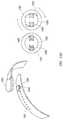
- FIG. 5Aillustrates an example of a top-view of the device's display relative to other device components.
- Outer ring 510may be attached to the front surface 512 of device 508 , or it may be independent of front surface 512 .
- display 506does not rotate regardless of rotation of outer ring 510 surrounding display 506 . That may be achieved by attaching display 506 to the portion 504 of display module that is affixed to band 502 , or by programming displayed content to remain static while the display unit rotates. In the latter case, displayed content is rotated such that the visual vertical axis of the image displayed by the display unit remains parallel to the band at all times.
- a display modulemay additionally incorporate one or more sensors on or near the same surface as the display.
- the display modulemay include a camera or other optical sensor, microphone, or antenna.
- One or more sensorsmay be placed in an inactive area or of the display.
- FIG. 5Billustrates device 522 with a camera module 516 placed coplanar with the battery below display 520 , with optical opening 514 positioned under the clear section of display 520 .
- Camera module 516may be placed between gird line connectors 518 for display 520 .
- Any camera or other suitable sensorsmay be placed coplanar with the display, such as antenna 524 of FIG. 5C , which is placed is inactive area 526 .
- sensorsmay be placed below or above the display, may be placed in any suitable location in or on the outer body of the device, may be placed in any suitable location in or in the band of a device, or any suitable combination thereof, as described more fully herein.
- a front-facing-cameramaybe placed under the display, on the display, or above the display.
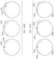
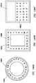
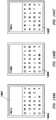
- the packaging of a circular displayincludes an inactive area, as illustrated in FIG. 5D .
- row drive lines powering the displayare routed to the nearest lateral edge, then either routed down along the inactive areas, or connected directly to the driver integrated chips along that edge.
- a number of approachesmay be taken to reduce the amount of inactive area for the display. For example, particular embodiments reduce the size of the inactive area by rerouting grid control lines powering the display to one edge of the display.
- FIG. 5Dillustrates grid control lines 532 routed to one edge of display 536 and connected to a connector 538 routing the lines to the processing center of device 528 . In that configuration, inactive area 530 may be minimized.
- FIG. 5Eillustrates another example embodiments for reducing the inactive area of a display 554 of device 540 by creating a polygonal-type display outline, with a circular area masked in the center by one or more masks 550 .
- Connectors 552are arranged in a polygonal design. Rows 546 and columns 542 of grid lines are routed to the nearest connector 552 .
- connectors 552connect to a flexible circuit behind the display that carries the driver chip. Due to the reduced density of connection, the electronics of FIG. 5E may be easier to connect to a flexible printed circuit board (FPC board) and thus increases yield.
- FPC boardflexible printed circuit board
- one or more inactive areas 548can be further reduced while allowing the integrated circuit to remain on a stable and flat surface.
- This designis particularly suited to OLED displays, but may be used with LCDs, given that a backlight unit (BLU) may be laminated on to the device before the FPC board is connected. While the above example illustrates a polygonal arrangement of connectors, any suitable arrangement of connectors may be used as long as all pixels are reached by grid lines.
- FIG. 5Fillustrates an example physical arrangement and sizing of a display of a device.
- the devicehas a diameter of D 4 , such as for example approximately 41.1 millimeters.
- the deviceincludes one or more inactive areas having a width D 3 , such as for example approximately 1.55 millimeters.
- the deviceincludes a visible area with a diameter D 2 , such as for example approximately 38 millimeters.
- the deviceincludes connectors 568 for column lines 564 and row lines 566 .
- Connectors 568may be coupled to the device by one or more FPC bonds 570 , which have a width of D 1 , such as for example approximately 0.2 millimeters.
- Connectors 568may have a width D 5 , such as for example approximately 6 millimeters.
- Display connector FPC 556may be used to connected the electronics of the display, such as for example circuitry from connectors 568 , to driver chip 558 , which may be below the display or on the back of the device body
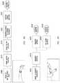
- FIGS. 6A-Cillustrate example cross-sectional views of a device display, including manufacturing of the device.
- hotbar knife 605is used to solder the flexible printed circuit(s) 610 coupling the electronics of the display to processing electronics of the device.
- a support 615may be used to stabilize the FPC 610 during this process.
- FIG. 6Billustrates the connected FPC 620 , which has been folded over (portion 625 ) and glued to the back of the display using adhesive 630 .
- FIG. 6Cillustrates an example finished display.
- FPC 645has been laminated to the back of protective display glass 635 , and is bent over the front of glass 635 and is attached to the front of glass 635 via microbond 649 .
- Adhesive 650connects the FPC 645 to the device.
- the FPCpass over driver chip 655 , which is connected to device by adhesive 650 .
- all processing and RF componentsare located within the body of the device, which may create a challenge in allowing RF signals to pass out of the device.
- the FPC boardmay additionally be attached to sides of the polygon where there is no connection to the display itself to allow the mounting of strip line, stub, ceramic, or other antennae (or other suitable sensors) in the same plane as the display, as illustrated in FIG. 5C .
- the antenna of FIG. 5Cis coplanar with the display, interference from the dense mesh of wiring (e.g. as illustrated in FIG. 5E ) from the display is reduced.
- a displaymay be shielded from electromagnetic interference with the main processor board using a metal shield.
- the metal shieldmay also be used as a heat sink for the battery, and thus may improve charge or discharge rates for the battery.
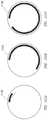
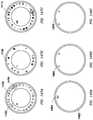
- an wearable electronic devicemay include one or more outer elements (which may be of any suitable shape) about the device body.
- FIG. 7Aillustrates an outer element by an example outer ring 710 about a display 705 .
- Outer ringmay be composed of any suitable material, such as for example stainless steel or aluminum.
- outer ring 710may be rotatable in one direction, both directions, or may be used in both configurations based on e.g. a switch.
- one outer ring 710may rotate in one direction while a second outer ring 710 rotates in the opposite direction.
- Outer ring 710may be coupled to base 720 of the device by a retention ring 715 .
- FIGS. 7C-Dillustrate retention ring 715 affixed to base 720 via screws 725 screwed into corresponding posts of base 720 .
- the devicemay include fasteners/spacers 730 , as illustrated in FIG. 7C .
- detents or encoders (which may be used interchangeably, where suitable) of an outer elementmay provide a user with haptic feedback (e.g. a tactile click) provided by, for example, a detent that allows the user to determine when the element has been moved one “step” or “increment”, which may be used interchangeably herein.
- This clickmay be produced directly via a mechanical linkage (e.g. a spring mechanism) or may be produced electronically via a haptic actuator (e.g. a motor or piezo actuator).
- a motormay provide resistance to motion of a ring, such as for example by being shorted to provide resistance and unshorted to provide less resistance, simulating the relative high and low torque provided by a mechanical detent system.
- magnetic systemsmay be used to provide the haptic feel of a detent.
- a solenoid mechanismmay be used to disengage the detent spring or escapement as needed. The spring or escapement provides the actual mechanical feedback.
- this arrangementallows the device to skip a number of détentes as needed, while re-engaging the detent at exact intervals to create the sensation of detents, such as those that have changed size.
- a rotatable outer element(such as, for example, the outer ring) may be magnetized, such as by an electromagnetic used to attract the ring at “detent” positions, increasing torque and simulating detent feedback.
- a rotatable outer elementmay have alternating north-south poles, which repels and attracts corresponding magnetic poles in the device body.
- a permanent magnetmay be used to lock the ring in place when the electromagnet is not in use, preventing freewheeling.
- an easily-magnetizable ferromagnetic alloymay be used within a solenoid.
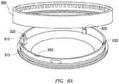
- FIG. 8Aillustrates an outer ring 805 with notches for a spring-based detent system etched onto the inner surface of outer ring 805 .
- Springs 820attached to spring posts 810 .
- Retention ring 815may be made of Delrin, steel, or any other suitable material, and may be segmented or solid/continuous.
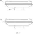
- FIG. 8Billustrates an example outer ring having small notches 830 that engage a spring-loaded element to provide haptic feedback from the illustrated detent.
- the feedbackmay be produced in rapid synchrony with the motion of the ring, and must have a sufficient attack and decay rate such that successive movements of the ring are distinguishable from each other.
- an outer ringmay be freely (e.g.
- a ringmay be capable of both continuously rotating and rotating in steps/increments, based on, for example, input from a user indicating which rotational mode the outer ring should be in.
- the ringmay also or in the alternative rotate freely in one direction and in increments in the other. Different functionality may occur based on the rotational mode used. For example, rotating in continuous mode may change a continuous parameter, such as e.g. volume or zooming, while rotation in incremental mode may change a discrete parameter, such as e.g. menu items or contacts in a list, as described more fully herein.
- the ringwhen rotating freely the ring may provide haptic feedback to the user, for example a force applied such that the ring appears to rotate in viscous media (e.g. the more quickly the ring is rotate the more it resists rotation).
- an outer ringmay be depressed or raised in the direction of the axis the outer ring rotates about, such as for example as part of a gesture or to change rotational modes.
- an outer ringmay have touch-sensitive portions.
- an encoder or detentmay be used to determine the position of the outer ring relative to the device body.
- Particular embodimentsutilize an encoder that is affixed to the device body, as illustrated by encoder 230 of FIG. 2 .
- the encoderis part of the inner surface of the outer ring itself, as illustrated by printed optical elements 825 in FIG. 8B .
- the outer ringacts as the rotating part of the encoder directly.
- An optical encoder patternis printed onto the inner surface, and is read out by an optical module on the processing board.
- the encoder on the interior of the outer ringshould have sufficient optical contrast for detectors, and may be etched on the outer ring via e.g. printing or laser-etching.
- the inner and outer ringsmay be environmentally sealed with a low-friction ring (such as for example, ring 840 of FIG. 8C ) made of a material such as Teflon or Delrin that maintains a tight fit while preventing contaminants from entering the inner part of the device.
- a lip on the inner ringmay engage a similar lip on the outer ring, allowing the two rings to be joined while still allowing free rotation.
- a larger lip at the bottom of the inner ringprovides further sealing by deflecting environmental hazards from below.
- sealing ring 915may fit into groove 905 of the base, which may include a grip area 910 .
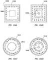
- a retention ring connecting the outer ring to the body of the devicemay have strain gages to detect pressure on the outer ring.
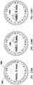
- FIG. 10illustrates a retention ring connected to four strain gauges (which are also connected to the inner body) that are symmetrically placed around the ring.
- the four strain gaugesmay be an electronic component detecting strain.
- strain gaugesIn contrast, squeezing a larger portion of the outer ring will likely produce a symmetric strain on opposite pairs of strain gauges (e.g. due to elongation of the ring under pressure). The relative difference in strain between the two pairs of strain gauges thus differentiates intentional squeezing of the outer ring from regular motion of or contact with the outer ring. While this disclosure describes specific examples of the number and placement of strain gauges in the retention ring, this disclosure contemplates placement of any suitable number of strain gauges in any suitable component of the device to detect pressure on the component. As one example, strain gauges may be placed on the band of the device or in the outer ring.
- the detected strainmay result in any suitable functionality.
- the outer ringsuch as for example by a user squeezing the outer ring
- feedbackmay be provided to the user. That feedback may take any suitable form, such as tactile feedback (e.g. vibration, shaking, or heating/cooling), auditory feedback such as beeping or playing a particular user-defined tone, visual feedback (e.g. by the display of the device), or any other suitable feedback or combination thereof.
- tactile feedbacke.g. vibration, shaking, or heating/cooling
- auditory feedbacksuch as beeping or playing a particular user-defined tone
- visual feedbacke.g. by the display of the device
- Functionality associated with squeezing a ringis described more fully herein, and this disclosure contemplates any suitable functionality resulting from strain or pressure placed on and detected by any suitable components.
- An wearable electronic devicemay be attached to a band to affix the device to the user.
- a “band”may encompass any suitable apparatus for affixing a device to the user, such as for example a traditional band 1405 that can be worn around the arm, wrist, waist, or leg of the user, as illustrated by way of example in FIG. 14A ; a clip 1415 for affixing to a piece of clothing, as illustrated by way of example in FIG. 14B ; a necklace or bracelet 1420 configuration, as illustrated by way of example in FIG. 14C ; a keychain 1425 or other accessory configuration to secure the device, for example, in the user's pocket, as illustrated by way of example in FIG. 14D ; or any other suitable configuration.
- FIG. 11illustrates various embodiments for wearing the device, such as for example around a neck as illustrated in 1105 ; pinned to clothing (such as, for example, the chest as illustrated by 1110 ); on a belt as illustrated in 115 ; on an appendage (such as, for example, an arm as illustrated in 1120 ); on the wrist as illustrated in 1125 , or in a pocket as illustrated in 1130 . While this disclosure describes specific examples of bands and ways of affixing devices to a user, this disclosure contemplates any suitable bands or ways of affixing a device to a user.
- sensors and corresponding electronicsmay be attached to a band, where appropriate.
- the bands of FIGS. 14A-14Cmay be suitable for housing an optical sensor. All illustrated, particular embodiments may be suited for including a touch-sensitive area.
- This disclosurecontemplates any suitable bands including any suitable sensors or electronics, such as for example communication components (such as antennae), environmental sensors, or inertial sensors.
- the bandmay be detachable from the device, and may communicate remotely with the device when not attached to the device.
- wiring associated with electrical components in the bandmay also be housed in the band, for example to minimize the volume of the device or to minimize electromagnetic interference with internal device components.
- devicesthat may cause high levels of internal EMI (for example, camera or communication systems), that may require additional volume (for example, battery or speaker), that may require the environmental seal of the main body (for example, power/data connector), or that may require additional contact with the skin of the user (for example, biometric sensors) may benefit by housing at least some of electronics in a band of the device.
- a display modulewhen wiring is contained in a band, a display module may be attached to the band such that electronic connections made to or via the band do not twist when the outer ring is rotated.
- the modulemay use a connector that is user-removable, such that the display module or device body can be removed and attached by the user at will.
- a band 1215 as illustrated in FIG. 12Amay be attached to the body by being placed over one or more posts 1205 and then affixed to those posts using fasteners (e.g. screws) 1210 .
- a retention plate 1215may be used to secured the band to device 1225 , as illustrated in FIG. 12B .
- This disclosurecontemplates any suitable interface between the band and the device.
- a USB interfacemay be provided between the band and the body of the device, to for example communicate data between the device and the band or components of the device and components of the band.
- an interfacemay enable a user of the device to easily detach, attach, or change the band of the device.
- FIG. 13Aillustrates example structures for fastening band 1305 having a camera module 1310 to a wearer of device 1300 .
- Fastenersmay include one or more snaps 1315 , holes 1320 and 1335 and corresponding components, clasps 1340 , or clips 1325 with push buttons 1330 .
- FIG. 13Billustrates an example mechanism for affixing band 1301 to a wearer using clips 1311 and 1303 .
- Components 1309insert in the cavity on the other side of components 1307 to fasten band 1301 .
- FIG. 13Bfurther illustrates example internal mechanisms for clips 1303 and 1311 .
- Component 1317 of clip 1313may include one or more magnetic portions, which may be attracted to magnets in cavity 1323 .
- component 1317may include a magnetic portion at its outer edge, and a magnet of opposite polarity may be placed in front of spring 1319 to attract the magnet of component 1317 .
- Components 1317may then fill cavity 1323 , fastening clip 1313 to clip 1303 by coupling of the magnets.
- components 1321may be used to engage springs 1319 , which force components 1317 out of cavity 1323 .
- Clip 1313may be detached from clip 1303 .
- magnetsmay also be placed within clip 1313 , for example to assist removal of clip 1313 when springs 1319 are engaged or to prevent components 1317 from sliding in and out of clip 1313 when not fastened to clip 1303 .
- one or more magnetsmay be placed in the center of clip 1313 equidistant from components 1317 and in the same plane as components 1317 , attracting magnets of each component (and thus, the components themselves) toward the center of clip 1313 .
- FIG. 13Cillustrates example structure for affixing a band 1327 using fasteners 1333 and 1331 , for example through the use of cavity 1329 and components 1337 and 1341 .
- FIG. 13Cillustrates the internal structure of fasteners 1331 and 1333 .
- Fasteners 1339(corresponding to fastener 1333 ) includes components 1337 .
- components 1341attach to components 1337 , and may be secured by extending over a lip of fastener 1339 .
- magnetsmay be placed in or on fasteners 1333 and 1331 to fasten them together.
- a magnetmay be placed at the edge of each of component 1341 and 1337 .
- a magnetmay be placed in fastener 1343 , for example to assist removal of component 1341 from component 1337 or to prevent components 1341 from sliding in and out of fastener 1343 when not affixed to fastener 1339 .
- one or more magnetsmay be placed in the center of fastener 1343 equidistant from components 1341 and in the same plane as components 1341 , attracting magnets at the end of each component (and thus, the components themselves) toward the center of fastener 1343 .
- FIG. 13Dillustrates an alternative arrangement for affixing band 1351 using fasteners 1349 and 1353 .
- fastener 1357corresponding to fastener 1353
- disengaging components 1359which may be rounded
- fastener 1361corresponding to fastener 1349
- one or magnetsmay be used to affix fasteners 1357 and 1361 to each other and/or remove fasteners 1357 and 1361 from each other.
- magnetsmay be placed in cavities 1363 and at the outer (convex) edge of components 1359 , attracting components 1359 into cavities 1363 and securing fastener 1361 to fastener 1357 .
- magnetsmay be placed on the inner edge of components 1359 (i.e., on the concave surface of components 1359 ), attracting components 1359 into fastener 1361 , for example to assist removal of components 1359 from cavities 1363 or to prevent components 1359 from sliding in and out of fastener 1361 when not affixed to fastener 1357 .
- Corresponding magnetsmay also be placed on the surfaces of fastener 1361 that are in contact with components 1359 when those components are not extended into cavities 1363 . In other words, those magnets may attract (and, in particular embodiments, ultimately make directed contact with) magnets on the concave surface of components 1359 , securing components 1359 to fastener 1361 .
- FIGS. 13E-13Gillustrate example embodiments of affixing a band 1369 with camera module 1373 to itself, for example when worn by a user of device 1367 .
- one or more magnets 1371 on one side of band 1369may be attracted to one or more magnets 1379 on the other side of band 1369 .
- Magnetsmay be strips of magnetic material partially crossing a band, as illustrated by magnetic strip 1307 in FIG. 13H , may be strips of magnetic material fully cross the band, as illustrated by strips 1321 and 1327 in FIG. 13I , or may be areas of magnetic material 1393 as illustrated in FIG. 13F .
- band 1369may include holes 1391 and one or more posts 1377 for securing band 1369 to the wearer of device 1367 .
- FIG. 13Gillustrates fasteners 1387 (e.g. screws 1396 ) affixing to fasteners 1371 (e.g. nut with covering 1395 ) to affix band 1381 to a wearer of device 1367 using holds 1383 ( 1398 ).
- a band containing electrical componentsmay also incorporate a traditional physical contact connector, as illustrated by connector 250 of FIG. 2 .
- the connectormay allow for connectivity with the device, for example, for charging, system updates, debugging, or data transfer.
- a connectormay be of the pogo variety or may be plated surfaces to which a charging cable can interface by contact.
- Such connectorsmay be plated in precious metals to prevent corrosion from exposure to moisture from the environment and the human body.
- physical connectorsmay be used only for power, and data may be transferred using short-range communication modalities, such as BLUETOOTH, near field communication (NFC) technology, or WI-FI.
- a bandmay be used to house flexible batteries (such as, e.g., lithium-based batteries) to increase the energy storage of the device.
- flexible batteriessuch as, e.g., lithium-based batteries
- energy storage capacitymay be tied to total volume
- batteries internal to the bandincrease the storage capacity for volume-limited wearable devices without impacting the total size of the device body.
- an wearable electronic devicemay include one or more sensors on or in the device.
- an wearable electronic devicemay include one or more optical sensors or depth sensors.
- Optical sensorsmay be placed in any suitable location, such as for example on the face of the device, on a band facing outward from the user's body, on a band facing opposite the face, on a band facing toward the user's body, or any suitable combination thereof.
- FIG. 15illustrates a device 1500 with a band having an outward-facing optical sensor 1505 . Placement of an optical sensor on the band may reduce the number of high-frequency signals inside the case, allowing for lighter shielding within the device body and thus weight and volume savings.
- 14A-14Dillustrate example camera placements for different embodiments of an wearable electronic device.
- electronicssuch as that for processing camera input may be located in the band as well, for example in a “volcano” shape housing the camera, as illustrated by housing 125 in FIG. 1 .
- other sensorsmay be placed near an optical sensor, such as for example in the same housing as the optical sensor on the band of the device.
- a depth sensormay be used in conjunction with an optical camera to enhance display or detection of a device's environment, or to determine which object a user is pointing at or interacting with via a gesture.
- placement of an optical sensor on the bandmay be adjustable by the user within a predetermined range.
- placement of an optical sensor on the bandmay be optimized such that the sensor is conveniently aimable by the user. For example, as illustrated by FIG. 15 if the user wears the device about the user's wrist, optical sensor 1505 may be placed in an outward-facing fashion such that the optical sensor aims outward from the user's body when the user's palm is roughly parallel to the ground.
- placement of an optical sensormay be such that the user may view the display of the device while the sensor is pointing outward from the user's body.
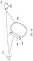
- the usermay view content captured by the optical sensor and displayed by the device without blocking the user's view of the physical scene captured by the sensor, as illustrated by the viewing triangle in FIG. 16 .
- a display 1620 of a device 1600may have an associated viewing cone, e.g., the volume within which the display can be reasonably viewed.
- user 1615(1) views a real trophy 1610 and (2) views an image of the trophy on display 1620 of device 1600 from within the viewing cone of display 1620 by aiming sensor 1605 at the real trophy.
- Sensor 1605has an associated angle of view corresponding to a volume within which images can be reasonably captured by sensor 1605 . Note that in the example of FIG. 16 , sensor 1605 is placed such that the user can conveniently aim sensor 1605 outward while maintaining display 1620 of device 1600 in a direction facing the user, and can do so without device 1600 blocking the user's view of trophy 1610 .
- FIG. 17illustrates an example angle of view for an optical sensor.
- a usermay view both object 1725 and an image 1710 or 1715 of object 1725 as displayed on device 1700 .
- the user's hand 1720is in the angle of view, the user may view object 1725 , hand 1720 , and an image 1710 of object 1725 and hand 1720 on display 1700 of the device.
- hand 1720is not displayed by image 1715 presented on display 1700 .
- the device's sensorWhen worn by a user, the device's sensor may capture the user's hand/arm/fingers in the angle of view of the sensor while performing a gesture to be captured by the same or other sensors (e.g. a gesture selecting an object in the angle of view of the device, such as, for example, pinching, tapping, or pulling toward or pushing away).
- the sensor and displaymay be oriented such that, when worn by a user, an object to be displayed on the device is in the angle of view of the device while the device does not block the user's view of the object and the user's gaze is within the viewing cone of the device's display.
- a usermay interact with the image captured by the sensor or displayed on the device, such as, for example, by tapping on the portion of the display at or near where the image is displayed, by performing a gesture within the angle of view of the sensor, or by any other suitable method.
- This interactionmay provide some functionality related to the object, such as, for example, identifying the object, determining information about the object, and displaying at least some of the information on the display; by capturing a picture of the object; or by pairing with or otherwise communicating with the object if the object has pairing/communicating capabilities.
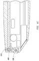
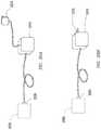
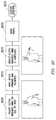
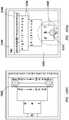
- an optical or depth sensor modulemay communicate with a device via a simple extension of the bus the optical sensor would use if it were directly mounted on the main printed circuit board (PCB), as illustrated in FIG. 18A .
- optical sensor 1825transmits data over flexible printed circuits or wiring 1820 to an integrated control 1810 , which in the example of FIG. 18A is located in or on device 1805 , which houses the main printed circuit board.
- FIG. 18Billustrates the optical sensor integrated circuit 1850 on or in the optical sensor module 1860 , which also houses optical sensor 1855 . Communication between the main printed circuit board of device 1830 and electronics in camera module 1860 occur via flexible printed circuit 1845 .
- 18Bmay allow an integrated circuit to compress and otherwise process the data and send it via a method that requires fewer signal lines, or that requires a smaller transfer of data. That may be beneficial since the band must flex when the user wears the device, and thus a smaller number of lines may be desirable. Such an approach can reduce the number of lines to one or two signal lines and two power lines, which is advantageous for packaging, molding, and reliability.
- one or more of the electronics described abovemust be shielded to prevent electromagnetic interference from the long high-frequency cabling.
- the use of a parallel busis common is such cases, and may require the use of a larger cable or FPC.
- the camera control integrated circuitmay be mounted directly on a small circuit board at the optical module, as illustrated in FIGS. 18A-B .
- An wearable electronic devicemay include any suitable sensors.
- one or more sensors or its corresponding electronicsmay be located on a band of the device, in or on the body of a device, or both.
- Sensorsmay communicate with each other and with processing and memory components through any suitable wired or wireless connections, such as for example direct electrical connection, NFC, or BLUETOOTH.
- Sensorsmay detect the context (e.g. environment) or state of the device, the user, an application, or another device or application running on another device.
- This disclosurecontemplates an wearable electronic device containing any suitable configuration of sensors at any suitable location of the wearable electronic device.
- this disclosurecontemplates any suitable sensor receiving any suitable input described herein, or initiating, involved in, or otherwise associated with the provision of any suitable functionality or services described herein.
- touch-sensitive sensorsmay be involved in the transition between graphical user interfaces displayed on the device, as described more fully herein.
- This disclosurefurther contemplates that functionality associated with the wearable device, activation/deactivation of sensors, sensitivity of sensors, or priority of sensor processing may be user-customizable, when appropriate.
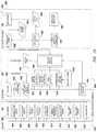
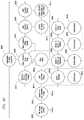
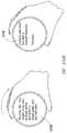
- FIG. 19illustrates an example sensor detection system and illustrates example sensors for an wearable electronic device. Sensors send data in a sensor-specific format to the sensor hub subsystem of the device.
- sensors 19 A illustrated in example sensor module 1924may include one or more: face-detecting cameras 1902 , outward-facing cameras 1904 , face proximity sensors 1906 , face touch sensors 1908 , band touch sensors 1910 , acoustic skin touch sensors 1912 , inertial measurement system (IMU) 1914 , gravity vector sensors 1916 , touch sensors 1918 and 1920 , and any other suitable sensors 1922 .
- Data from sensorsis sent to sensor hub 19 B illustrated in example sensor hub module 1944 . The data is conditioned and cleaned of noise in steps 1928 and 1930 as needed and transferred to a locked-state detector 1942 .
- Locked state detector 1942detects when the device is inactive, and disables sensors as needed to conserve power, while monitoring the sensor data for a gesture or other suitable input that may reactivate the device.
- numeric gesture detectorsreceive sensor output and compare that output to one or more numeric thresholds to determine an outcome.
- Heuristic gesture detectors 1934receive sensor output and make decisions based on one or more decision trees, such as for example ANDing rules applied to more than one threshold.
- Pattern-based gesture detectors 1938evaluate sensor input against a predetermined library of gesture patterns 1940 , such as for example patterns determined by empirical evaluation of sensor output when a gesture is performed.
- One or more gesture priority decoders 1948evaluate output from gesture detectors, locked state detectors, or both to determine which, if any, of the detected gestures should be utilized to provide functionality to a particular application or system-level process. More broadly, in particular embodiments, when the device is active, application-requested or system-requested sensor detectors are activated in turn and provide their data to the sensor priority decoder. In particular embodiments, the priority detector determines which, if any, of a plurality of sensor input to process, and this disclosure contemplates that combined input from multiple sensors may be associated with functionality different than functionality associated with each sensor input individually. The decoder decides when a sensor has been detected with sufficient certainty, and provides sensor data to the sensor hub driver.
- FIG. 19illustrates example sensor hub driver 1950 , application APIs 1952 , system navigation controllers 1954 for, for example, determining appropriate system functionality (for example, system-level navigation 1962 through a graphical user interface of the device), and application-level gesture priority detectors for applications 1956 .
- sensor hub 19 B and application processor 19 Cillustrated in example application processor module 1964 ) of FIG. 19 are illustrated as separate entities, they may be expressed by (and their functions performed by) at least some of the same or similar components.
- the boundaries delineating the components and functions of the sensor hub and the application processormay be more or less inclusive. The boundaries illustrated in FIG.
- sensors 19are merely one example embodiment.
- functions executed by and components of the sensor hub system and application processormay occur or be in the device body, in the band, or both.
- Particular embodimentsmay use more than one sensor hub or application processor, or components therein, to receive and process sensor data.
- Sensorsmay internally produce sensor data, which may be simply filtered or reformatted by, for example, a detector or data conditioner.
- Raw datamay be formatted to an uniform format by the data formatter for ingestion by the Application API.
- Recognizersmay use numeric models (such as decision trees), heuristic models, pattern recognition, or any other suitable hardware, software, and techniques to detect sensor data, such as gesture input. Recognizers may be enabled or disabled by the API. In such cases, the associated sensors may also be disabled if the recognizer is not to receive data from the sensors or is incapable of recognizing the sensor data.
- a devicemay incorporate a database of sensor outputs that allow the same detector to detect many different sensor outputs.
- a sensor priority decodermay suppress or pass through sensor output based on criteria supplied.
- the criteriamay be a function of the design of the API.
- recognizersmay ingest the output of more than one sensor to detect sensor output.
- multiple sensorsmay be used to detect similar information.
- a normal and a depth sensing cameramay be used to detect a finger
- both a gyroscope and a magnetometermay be used to detect orientation.
- functionality that depends on or utilizes sensor informationmay substitute sensors or choose among them based on implementation and runtime considerations such as cost, energy use, or frequency of use.
- Sensorsmay be of any suitable type, and as described herein, may be located in or on a device body, in or on a band, or a suitable combination thereof.
- sensorsmay include one or more depth or proximity sensors (terms which may be used interchangeably herein, when appropriate), such as for example infrared sensor, optical sensors, acoustic sensors, or any other suitable depth sensors or proximity sensors.
- a depth sensormay be placed on or near a display of a device to detect when, e.g., the user's hand, finger, or face comes near the display.
- depth sensorsmay detect any object that a user's finger in the angle of view of the depth sensor is pointing to, as described more fully herein.
- sensorsmay include on or more touch-sensitive areas on the device body, band or both.
- Touch-sensitive areasmay utilize any suitable touch-sensitive techniques, such as for example resistive, surface acoustic wave, capacitive (including mutual capacitive or self-capacitive), infrared, optical, dispersive, or any other suitable techniques.
- Touch-sensitive areasmay detect any suitable contact, such as swipes, taps, contact at one or more particular points or with one or more particular areas, or multi-touch contact (such as, e.g., pinching two or more fingers on a display or rotating two or more fingers on a display).
- touch-sensitive areasmay comprise at least a portion of a device's display, ring, or band. Like for other sensors, in particular embodiments touch-sensitive areas may be activated or deactivated for example based on context, power considerations, or user settings. For example, a touch-sensitive portion of a ring may be activated when the ring is “locked” (e.g. does not rotate) and deactivated when the ring rotates freely.
- sensorsmay include one or more optical sensors, such as suitable cameras or optical depth sensors.
- sensorsmay include one or more inertial sensors or orientation sensors, such as an accelerometer, a gyroscope, a magnetometer, a GPS chip, or a compass.
- output from inertial or orientation sensorsmay be used to activate or unlock a device, detect one or more gestures, interact with content on the device's display screen or a paired device's display screen, access particular data or activate particular functions of the device or of a paired device, initiate communications between a device body and band or a device and a paired device, or any other suitable functionality.
- sensorsmay include one or more microphones for detecting e.g. speech of a user, or ambient sounds to determine the context of the device.
- a devicemay include one or more speakers on the device body or on the band.
- sensorsmay include components for communicating with other devices, such as network devices (e.g. servers or routers), smartphones, computing devices, display devices (e.g. televisions or kiosks), audio systems, video systems, other wearable electronic devices, or between a band and a device body.
- network devicese.g. servers or routers
- smartphonese.g. servers or routers
- computing devicese.g. computing devices
- display devicese.g. televisions or kiosks
- audio systemse.g. televisions or kiosks
- video systemse.g. televisions or kiosks
- sensorsmay include NFC readers/beacons, BLUETOOTH technology, or antennae for transmission or reception at any suitable frequency.
- sensorsmay include sensors that receive or detect haptic input from a user of the device, such as for example piezoelectrics, pressure sensors, force sensors, inertial sensors (as described above), strain/stress sensors, or mechanical actuators. Such sensors may be located at any suitable location on the device.
- components of the devicemay also provide haptic feedback to the user. For example, one or more rings, surfaces, or bands may vibrate, produce light, or produce audio.
- an wearable electronic devicemay include one or more sensors of the ambient environment, such as a temperature sensor, humidity sensor, or altimeter.
- an wearable electronic devicemay include one or more sensors for sensing a physical attribute of the user of the wearable device. Such sensors may be located in any suitable area, such as for example on a band of the device or on base of the device contacting the user's skin.
- sensorsmay include acoustic sensors that detects vibrations of a user's skin, such as when the user rubs skin (or clothing covering skin) near the wearable device, taps the skin near the device, or moves the device up and down the user's arm.
- a sensormay include one or more body temperature sensors, a pulse oximeter, galvanic-skin-response sensors, capacitive imaging sensors, electromyography sensors, biometric data readers (e.g. fingerprint or eye), and any other suitable sensors.
- Such sensorsmay provide feedback to the user of the user's state, may be used to initiate predetermined functionality (e.g. an alert to take particular medication, such as insulin for a diabetic), or may communicate sensed information to a remote device (such as, for example, a terminal in a medical office).
- An wearable electronic devicemay include one or more charging components for charging or powering the device.
- Charging componentsmay utilize any suitable charging method, such as capacitive charging, electromagnetic charging, trickle charging, charging by direct electrical contact, solar, kinetic, inductive, or intelligent charging (for example, charging based on a condition or state of a battery, and modifying charging actions accordingly).
- Charging componentsmay be located on any suitable portion of the device, such as in or on the body of the device or in or on the band of a device.
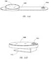
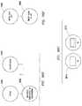
- FIG. 20Aillustrates a charger 2000 with slot 2005 for connecting a charging component with the charger.
- slot 2005may use friction, mechanical structures (such as latches or snaps), magnetism, or any other suitable technique for accepting and securing a prong from a charging component such that the prong and charger 2000 make direct electrical contact.
- FIG. 20Cillustrates prong 2015 on band 2010 utilizing pogo-style connectors to create a circuit connection between charger 2022 and band 2010 through contacts 2020 .
- prong 2015may be on charger 2022 and slot 2005 of FIG. 20A may be on the band or body of the wearable device.
- contacts 2020(such as, for example, pogo-style connectors) may be on the body of the device, which may be used to create a circuit between the band or the charger for charging the device.
- Charger 2000 of FIG. 20Amay be connected to any suitable power source (such as, for example, power from an alternating current (AC) outlet or direct current (DC) power from a USB port on a computing device) by any suitable wired or wireless connection.
- ACalternating current
- DCdirect current
- Charger 2000may be made of any suitable material, such as acrylic, and in particular embodiments may have a non-slip material as its backing, such as e.g. rubber.
- charger 2000may be affixed or attached to a surface, for example may be attached to a wall as illustrated in FIG. 20B . Attachment may be made by any suitable technique, such as for example by mechanically, magnetically, or adhesively.
- an wearable electronic devicemay be fully usable while attached to the charger. For example, when a charging component is located on the body of the device, the device may sit in the charger while a user interacts with the device or other devices communicate with the device.
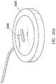
- FIGS. 21A-21Billustrate additional example chargers using e.g. inductive charger.
- a bandmay include one or more charging coils 2110 .
- this disclosurecontemplates charging coils (or any other suitable charging component) incorporated in or on the body of the device, in alternative to or in addition to on the band of the device.
- a magnetic field 2105 generated by e.g. charging surface 2115 or charging surface 2120passes through charging coil 2110 .
- Charging surface 2120 of FIG. 21Bmay improve the density of the magnetic field 2105 through charging coil 2110 relative to charging surface 2115 and allows more precise placement than charging surface 2115 , thus improving the charge transfer rate of the system.
- This disclosurecontemplates that, when suitable, charging may power components on or on the body of the device, components in or on the band, or both.
- the band or devicemay implement an antenna for a wireless charging solution. Since wireless charging operates optimally in the absence of ferrous metals, this allows a wider choice of materials for the body of the device, while allowing improved wireless charging transfer capacity by allowing the coil to be held between the poles of a charging driver (as described above) rather than being simply coplanar to the driver. As described above and illustrated in FIG. 2 , the active band may also incorporate a traditional internal physical contact connector 250 .
- a charging unit with an internal charge reservoirmay be associated with a wearable electronic device.
- the charging unitcan charge both an attached device and the charging unit's internal reservoir.
- the charging unitcan still charge an attached device from its reservoir of power until that reservoir is depleted.
- the chargerWhen only the charger is connected to a power source without a device, it still charges itself, so that it can provide additional power for the device at a later point.
- the charging unit described hereinis useful with and without being plugged into a power source, as it also can power any partially-charged device for a while when a person is not able to connect to a power source, for example when travelling, on plane, train station, outdoors, or anywhere a user might need charge for a device but does not have access to a power source.
- the devicecan be both in standby or in-use while the charger charges the device, and no modifications to the software or hardware of the target device is needed. Additional benefits of one or more embodiments of the invention may include reducing the number of items one must carry, providing the benefits of both a charger and a power pack, making charger useful to carry when on the move, and reducing the number of cables and connectors one must carry to extend the battery life of their devices.
- This disclosurecontemplates that such a charging unit may be applied to any suitable electronic devices, including but not limited to an wearable electronic device.
- FIGS. 22A-22Billustrate particular embodiments of an example charging unit 2210 with example connections 2205 to device 2200 and connections 2215 and 2220 .
- FIG. 22Aillustrates cable connectivity from the charging unit 2210 to device 2200 and to an external power source.
- FIG. 22Billustrates charging unit 2210 with cable connectivity from device 2200 and direct connectivity to a power source.
- This disclosurecontemplates any suitable connections between a device, the charging unit, and a power source charging the charging unit.
- connections both to the device and to the power sourcemay be direct, via cabling, or wireless.
- a charging unitcan charge a device from the charging unit's internal charging reservoir even when not connected to an external power source, and can charge itself, a connected device, or both when connected to an external power source.
- This disclosurecontemplates any suitable scheme for allocating charge between the charging unit and device. Such allocation scheme may depend on the amount of charge internal to the device, internal to the charging unit, the amount of power being consumed by the device, the charging capabilities of an external power source, or any suitable combination thereof.
- charging thresholdmay determine which allocation scheme to use. For example, one charging scheme may be used when the device is near full charge and the charging unit has little charge left, and another may be used when the device has little charge left.
- FIGS. 23-24illustrate example charging schemes for the charging unit and connected device.
- step 2405determines whether the device is fully charged. If yes, no further charging action is taken. If not, step 2410 determines whether the charger is connected to an external power source, such as for example line voltage. If so, the device is charged from that external source in 2425 . If not, step determines whether the charger has any power left, and if so, the device is charged from the charger's internal power source in step 2420 from line voltage rather than the charging unit's reservoir when the charging unit is connected to the line voltage.
- FIG. 23illustrates a similar decision tree.
- step 2310determines whether the device is fully charged, and if not, the device is charged from the power source the charger is connected to (step 2315 ).
- step 2320determines whether the charger is fully charged, and if not, the charger unit is charged from the power source in step 2325 .
- the allocation scheme usedmay be determined or customized by a user.
- FIGS. 25A-25Eillustrate example embodiments of energy storage and charging in a device and a charging unit.
- charge reservoir 2500 of the device and charge reservoir 2520 of the charging unitare both depleted.
- FIGS. 25B-25Cillustrate charging the charge reservoir 2500 of the device and charge reservoir 2505 of the device after the charging unit has been connected to external power source 2510 . After a short time, both charging unit and the device are charged simultaneously, with charging being distributed such that each is given the same percent of its total charge capacity. Both charging reservoir 2500 of the device and the charging reservoir 2505 of the charging unit are completely charged after some time, as illustrated in FIG. 25C .
- the amount of charge allocated to the device or the charging unitmay vary based on any suitable charge allocation scheme. For example, if the power conversion capability of the charging unit is limited, the charging unit's reservoir is nearly full and the device's charge reservoir is nearly empty, or the energy demand of the device is very high, the charging unit may prioritize the charging of the device before charging its internal reserves. As another example, charging of the charging unit may continue until a predetermined threshold charge has been reached.
- FIGS. 25D-25Eillustrate transfer of charge between the charging unit and the device when the charging unit is not connected to an external power source.
- a device with little charge remaining in its reservoir 2500is connected to a charging unit with a fully charged reservoir 2505 .
- this disclosurecontemplates any suitable charge allocation scheme between the device and the charger when the charger is not connected to an external power source. That allocation scheme may be the same as or different from the allocation schemed used when the charging unit is connected to an external power source.
- FIG. 25Eillustrates an allocation scheme that maximizes the charge of the charging reservoir 2500 of the device. As long as the charging unit still has charge, it continues charging device until the device is fully charged or until the charging reservoir 2505 of the charger is completely empty.
- FIG. 26illustrates an example internal architecture of an example charging unit 2600 .
- Line voltage converter 2605produces a lower voltage direct current from the high voltage line current 2610 . This voltage is fed both to battery charger/regulator 2630 and connector 2615 , to which a device can be connected via connection 2620 for charging.
- Battery charger 2630uses available power from line voltage converter 2605 to charge the energy reservoir (battery 2635 ). It may take an equal share of the power as the device, take a smaller share when the device demand is high (device priority), or take a larger share when internal power reserves are low (charger priority). Those priorities may be user-selectable.
- charger/regulator 2630when line voltage converter 2605 is not providing power, charger/regulator 2630 produces the appropriate charging voltage from the power on battery 2635 .
- Regulator 2630may be always on, or it may be switched on by connection to the device, or the press of a button that indicates the user wishes to charge the device. Once activated, regulator 2630 will charge the device until internal reserves are depleted. At that point, some charge may still remain in battery 2635 to improve battery life, but it will not be available to the user.
- the devicemay incorporate an emergency mode that allows access to some of this energy to gain a minimal amount of emergency usage time, at the cost of battery lifetime.
- Regulator 2630may continue to provide energy until either the device is unplugged, or until the device only draws a minimal amount of energy, indicating completion of charge. Finally, charger/regulator 2630 may include an on-demand display that shows the amount of energy remaining in reserve to the user. Since displays generally use energy, a button or other input may be used to trigger the display for a limited time. While FIG. 26 illustrates an example internal architecture of an example charging unit 2600 , this disclosure contemplates any suitable internal architecture of any suitable charging unit described herein, and contemplates that such a charging unit may be of any suitable size and shape.
- functionality or components of the devicemay be activated and deactivated, for example, to conserve power or reduce or eliminate unwanted functionality.
- a locked state detectordetects when the device is inactivated, and disables sensors as needed to conserve power, while monitoring the sensor data for a gesture or other suitable input that may reactivate the device.
- a devicemay have one or more power modes, such as sleep mode or fully active mode.
- the deviceis arm-worn, and a touch surface of the device may come in contact with objects and persons while in regular use.
- an accelerometer or other inertial sensor in the body or band of the devicecan be used to gauge the approximate position of the device relative to the gravity of the Earth.
- the touch screencan be locked and display disabled to reduce energy use.
- the systemmay power up the display and enable the touch screen for further interactions.
- a rate of change of the direction or magnitude of the gravity vectormay be used to wake or unlock a device.
- the devicemay be woken or unlocked.
- one or more inertial sensors in the devicemay detect a specific gesture or sequence of gestures for activating a display or other suitable component or application.
- the encoder of the deviceis robust to accidental activation, and thus can be left active so that the user may change between selections while bringing the device up to their angle of view. In other embodiments the encoder may be deactivated based on context or user input.
- particular embodimentsmay lock one or more sensors, particular functionality, or particular applications to provide security for one or more users.
- Appropriate sensorsmay detect activation or unlocking of the secure aspects of the device or of another device paired with or communicating with the wearable device. For example, a specific gesture performed with the device or on a touch-sensitive area of the device may unlock one or more secure aspects of the device.
- particular rotation or sequence of rotations of a rotatable ring of the devicemay unlock one or more secure aspects of the device, on its own or in combination with other user input. For example, a user may turn a rotatable ring to a unique sequence of symbols, such as numbers or pictures.
- the displaymay display the specific symbol(s) corresponding to each rotational input, as described more fully herein.
- the symbols usedmay be user-specific (such as, e.g., user pictures stored on or accessible by the device or symbols pre-selected by the user).
- different symbolsmay be presented to the user after a predetermined number of unlockings or after a predetermined amount of time.
- the example inputs described abovemay also or in the alternative be used to activate/deactivate aspects of the device, particular applications, or access to particular data.
- While this disclosuredescribes specific examples of user input unlocking secure aspects of a device, this disclosure contemplates any suitable input or combination of inputs for unlocking any secure aspect of the device. This disclosure contemplates that input or other suitable parameters for unlocking secure aspects of a device or activating/deactivating components of the device may be user-customizable.
- an wearable electronic devicemay detect one or more gestures performed with or on the device.
- Gesturesmay be of any suitable type, may be detected by any suitable sensors (e.g. inertial sensors, touch sensors, cameras, or depth sensors), and may be associated with any suitable functionality.
- one or more depth sensorsmay be used in conjunction with one or more cameras to capture a gesture.
- several depth sensors or camerasmay be used to enhance the accuracy of detecting a gesture or the background associated with a gesture.
- sensors used to detect gestures(or processing used to initiate functionality associated with a gesture) may be activated or deactivated to conserve power or provide security, as described more fully above. As shown above, FIG.
- gesturesmay include manipulation of another device while using the wearable device.
- a gesturemay include shaking another device while aiming, moving, or otherwise utilizing the wearable device.
- any of the gestures described hereinmay involve manipulation of another device. While the examples and illustrations discussed below involve specific aspects or attributes of gestures, this disclosure contemplates combining any suitable aspects or attributes of the gesture and sensor described herein.
- an wearable electronic devicemay detect one or more gestures performed with or on the device.
- Gesturesmay be of any suitable type, may be detected by any suitable sensors (e.g. inertial sensors, touch sensors, cameras, or depth sensors), and may be associated with any suitable functionality.
- one or more depth sensorsmay be used in conjunction with one or more cameras to capture a gesture.
- several depth sensors or camerasmay be used to enhance the accuracy of detecting a gesture or the background associated with a gesture.
- sensors used to detect gestures(or processing used to initiate functionality associated with a gesture) may be activated or deactivated to conserve power or provide security, as described more fully above.
- FIG. 19As described more fully above, FIG.
- gesturesmay include manipulation of another device while using the wearable device.
- a gesturemay include shaking another device while aiming, moving, or otherwise utilizing the wearable device.
- any of the gestures described hereinmay involve manipulation of another device. While the examples and illustrations discussed below involve specific aspects or attributes of gestures, this disclosure contemplates combining any suitable aspects or attributes of the gesture and sensor described herein.
- gesturesmay include gestures that involve at least on hand of the user and an appendage on which the device is worn, such as e.g. the other wrist of the user.
- a usermay use the hand/arm on which the device is worn to appropriately aim an optical sensor of the device (e.g. a camera or depth sensor) and may move or position the other arm/hand/fingers to perform a particular gesture.
- an optical sensor of the devicee.g. a camera or depth sensor
- the scene aimed atmay be displayed on the device's display, such that a user can view both the real scene, the scene as-displayed on the device, and the user's hand/arm/fingers, if in the angle of view of the.
- the displayed scenemay include the hands/fingers/arm used detected by the sensor and used to perform the gesture.
- FIGS. 27-28illustrate example gestures in which the user aims an outward-facing (e.g. away from the body of the user) sensor on the device (e.g. on the band of the device, as illustrated in the figures) and moves or positions his other arm/hand/fingers to perform a gesture. For example, in FIG.
- an outward sensordetects an object in the angle of view of the sensor 2705
- an outward sensor(which may be the same sensor detecting the object) detects one or more fingers pointing at the object 2710 , and when the pointing finger(s) are determined to be at rest 2715 , a gesture is detected 2720 .
- raw gesture data captured by the outward-facing cameracan be conditioned and cleaned of noise and that data can be sent to the Heuristic Gesture Detector.
- the Gesture Priority Decoderprocesses the gesture data and determines when the gesture has been identified with sufficient certainty. When the gesture has been identified, the gesture is sent to the Sensor Hub Driver which provides an API to the end applications and system controllers.
- FIG. 28illustrates an example gesture similar to the gesture of FIG. 27 ; however, the illustrated gesture includes the outward-facing sensor detecting a “tapping” motion of the finger(s) (e.g. that the finger(s) are moving away from the sensor). For example, the gesture of FIG.
- step 28may include detecting an object in the scene of a camera (or other suitable sensor) in step 2805 , detecting the finger in the scene in step 2810 , detecting a lack of lateral movement of the finger in step 2815 , detecting the finger tip moving further away from the sensor in step 2820 , and detecting a gesture in step 2825 .
- the gesture illustrated in FIG. 28may provide any suitable functionality.
- the “tapped” objectmay be selected from the objects displayed on the display screen.
- FIGS. 29-30illustrate example gestures where an object is detected with an outward-facing sensor along with movement of the user's fingers and hand.
- FIG. 29illustrates the outward-facing sensor detecting two fingers separated 2915 , the two fingers coming together (e.g. in a pinching motion) 2920 , and then the pinched fingers moving towards the sensor 2925 .
- the motion of the fingers coming together and moving toward the sensormay occur simultaneously or in sequence, and performing the steps in sequence (or time between steps in the sequence) or simultaneously may each be a different gesture.
- the two fingers illustratedare initially near together 3010 , and the outward-facing sensor detects the fingers moving apart 3020 and the hand moving away 3015 .
- FIG. 29illustrates the outward-facing sensor detecting two fingers separated 2915 , the two fingers coming together (e.g. in a pinching motion) 2920 , and then the pinched fingers moving towards the sensor 2925 .
- the motion of the fingers coming together and moving toward the sensormay occur simultaneously or in sequence, and performing
- the movement of the fingers and the handmay be simultaneous or in any suitable sequence.
- aspects of FIGS. 29-30may be combined to form a gesture.
- pinching fingers together and moving away from the sensormay be a unique gesture.
- the detected fingers or handmay be manipulating another device, and that manipulation may form part of the gesture.
- this disclosurecontemplates any suitable functionality associated with gestures illustrated in FIGS. 29-30 .
- FIGS. 31-32illustrate example gestures similar to FIGS. 29-30 , except that here all fingers are used to perform the gesture.
- the fingersare detected as initially close together (e.g. in a first) 3105 , the first is detected moving away from the sensor 3110 , and the sensor detects the first opening 3115 .
- the sequence of steps illustratedmay occur in any suitable order.
- FIG. 32illustrates the reverse of FIG. 31 .
- FIGS. 31-32may be associated with any suitable functionality.
- FIG. 31illustrates an example of sending all or a portion of content displayed on the device to another device, such as the television illustrated in FIG. 31 .
- the gestures of FIGS. 31-32may be implemented when the user performs the gestures with the wearable device in proximity of another device, such as a smart phone, tablet, personal computing device, smart appliance (e.g. refrigerator, thermostat, or washing machine), or any other suitable device.
- a smart phonee.g., Apple MacBook Air, a smart phone, Samsung Galaxy Tab, Samsung Galaxy Tab, or any other suitable device.
- smart appliancee.g. refrigerator, thermostat, or washing machine
- the described functionalityare merely examples of functionality that may be associated with gestures illustrated in FIGS. 31-32 , and this disclosure contemplates that other suitable gesture may perform the described functionality.
- FIGS. 33-37illustrate an outward-facing sensor detecting a hand or portion of an arm swiping in front of the sensor.
- swiping with the front of the handmay be a different gesture than swiping with the back of the hand.
- FIGS. 33-34illustrate the hand being swiped from right to left 3310 - 3315 and left to right 3410 - 3415 across the sensor's angle of view
- FIGS. 35-37illustrate the hand being swiped from bottom to top 3510 - 3515 (as well as 3735 - 3740 ) and top to bottom 3610 - 3615 (as well as 3710 - 3715 ) across the sensor's angle of view.
- the handmay initially start in the angle of view, pass through the angle of view, and exit the angle of view (as illustrated in FIG. 36 ); may start outside of the angle of view, pass through the angle of view, and exit the angle of view (as illustrated in FIG. 37 ); may start out of the angle of view, pass through a portion of the angle of view, and remain in the angle of view (as illustrated in FIGS. 33-35 ); or may start in the angle of view, pass through a portion of the angle of view, and remain in the angle of view.
- This disclosurecontemplates the hand being swiped at other angles, such as, e.g., entering at a 45 degree angle below and to the right of the device and exiting at a 45 degree angle relative to the top and to the left of the device. Further, this disclose contemplates detecting hand swipes in motions other than a straight line, such as curved swipes or triangular swipes.
- This disclosurecontemplates any suitable functionality associated with any or all of the gestures illustrated in FIGS. 33-37 , such as, for example, transitioning among user interfaces displayed on the device or among applications active and displayed on the device, opening or closing applications, or scrolling through displayed content (e.g. documents, webpages, or images). As reiterated elsewhere, this disclosure contemplates any suitable gesture associated with the functionality described in relation to FIGS. 33-37 .
- FIGS. 38-39illustrate example gestures where the outward-facing sensor detects the user's hand in the angle of view 3805 and detects one or more fingers pointing in a direction (along with, in particular embodiments, a portion of the user's hand or arm) 3815 .
- the gesture detectedmay depend on the fingers detected or direction the detected fingers are pointed.
- the fingermay be a thumb pointing upwards 3820
- the fingermay be a thumb pointing downwards 3920 .
- Any suitable functionalitymay be associated with gestures illustrated in FIGS. 38-39 , such as saving or deleting a file locally on the device or on an associated device, or approving or disapproving of changes made to settings or other content.
- FIG. 40illustrates an example gesture involving a shape made with multiple fingers or a portion of the hand in the angle of view of the outward-facing sensor.
- the shapemay be a ring 4010
- the gesturemay include fingers not involved in the shape pointing in a specific direction 4015 .
- a gesturemay include holding the shape 4020 (and possibly the other fingers) for a predetermined amount of time.
- FIGS. 41-42illustrate example gestures including covering all or a portion of the outward-facing sensor with the user's fingers or hand. Covering the sensor from the top of the device with a thumbs-down type gesture 4105 (as illustrated in FIG. 41 ) may be a different gesture than covering the sensor from the bottom of the device 4210 (as illustrated in FIG. 42 ) or the sides of the device.
- the direction of coveringmay be detected by, e.g., the shape of the hand when covering the device, the orientation of the hand when covering the device, data from other sensors indicating the direction in which the outward-facing sensor is being covered (e.g. detecting that the display and the outward-facing sensor are covered), or any other suitable technique.
- FIGS. 43-44illustrate example gestures where one or more of the user's fingers or portion of a hand/arm are detected in the angle of view of the outward-facing sensor 4305 / 4405 , and then move within the angle of view (or “frame”) to perform a specific gesture 4310 / 4320 / 4410 / 4420 .
- a gesturemay be any suitable movement or may be movement in a specific pattern.
- a gesturemay be associated with the fingers or a portion of the hand/arm detected. For example, a single pointing finger may be associated with a gesture 4305 (as illustrated in FIG. 43 ) or multiple fingers/a palm may be associated with a gesture 4405 (as illustrated in FIG. 44 ).
- the direction of the palme.g. front, back, at an angle
- FIG. 45illustrates an example gesture include detecting a shape with multiple fingers or the hand/arm of the user 4505 , and detecting movement of the shape in the angle of view 4510 / 4520 .
- FIG. 45illustrates the shape of FIG. 40 moving throughout the outward-facing sensor's angle of view.
- FIG. 46illustrates an example gesture involving detecting one or more fingers (some or all of a user's hand/arm) and their initial orientation, and subsequently detecting the change in orientation or the rate of change of orientation over time.
- FIG. 46illustrates detecting two fingers in a angle of view at step 4605 , detecting the fingers and edge of the hand in the angle of view at step 4610 , detecting the fingers making a “C” shape at step 4615 , decoding an initial orientation of the “C” shape at step 4620 , decoding a change in orientation of the “C” shape at step 4625 , determining a relative rotational value of the “C” shape at step 4630 , and detecting the gesture at step 4635 .
- This disclosurecontemplates any suitable shape made with the user's fingers/hand/arm.
- FIG. 47illustrates an example gesture that involves detecting the number of fingers in a particular position in the outward-facing sensor's angle of view.
- FIG. 47illustrates detecting fingertips in an angle of view at step 4705 , such as for example one outstretched thumb, an outstretched thumb and a finger, or an outstretched thumb and two fingers.
- the specific fingertip orientation configurationis detected at step 4710 , and the mapping of the configuration to at least a numeric count of the fingers is performed in step 4715 to detect the gesture in step 4725 .
- Each of the displayed imagesmay be a different gesture.
- This disclosurecontemplates any suitable position of the fingers that comprise a gesture. As for all other example gesture described herein, this disclosure contemplates any suitable functionality associated with the gestures.
- each gesture of FIG. 47may be associated with a contact to call, e-mail, or text and the detected gesture may activate the call, e-mail, or text to the contact assigned to the gesture.
- the position of the hand/arm/fingersmay indicate which method of contact should be used for the contact associated with the gesture.
- FIGS. 48-49illustrate example gestures involving dual sensors on the device.
- FIG. 48illustrates a sensor on the bottom band portion of the device. That sensors detects the position of the user's other hand relative to the device, and detects separation of the hand from the sensor.
- the gesturemay include determining that both hands are moving, such as for example by additional information supplied by one or more inertial sensors in the device or by an inward-facing (e.g. facing the body of the user) camera detecting movement of the device via change in scenery.
- a handis detected in the angle of view at step 4805 .
- a sensordetects that the hand is in a pinched shape at step 4810 and the same or another sensor detects that the device is in a horizontal orientation in step 4815 .
- a sensordetects the hand moving relative to the device at step 4820 and estimates the relative position at step 4825 .
- the gestureis detected at step 4830 .
- FIG. 49illustrates an example gesture also involving detection of the user's hand in the angle of view and subsequently moving away from a device sensor.
- the device sensoris positioned on the top of the device (e.g. a front-facing sensor).
- a handis detected in the angle of view of a front-facing camera in step 4905 .
- the handis detected in a pinched shape in step 4910 , and the device is detected in a horizontal orientation in step 4915 .
- the handmoves closer or further from the device in step 4920 , and the relative position estimate is performed in step 4925 , at which point the gesture is detected in step 4930 .
- FIGS. 50-58illustrate example gestures detected by at least one front-facing sensor (e.g. sensor on the top of the device). Any of the gestures of FIGS. 50-58 may be detected by sensors in any other suitable location (e.g. outward-facing, as described above), and any of the gestures detected by a sensor described in another location may be detected by a front-facing sensor, where appropriate.
- FIG. 50illustrates an example gesture involving one or more fingertips hovering above the device, and the front-facing sensor detects the fingertips in step 5005 , detects the position of the fingertips or motion (or lack of motion) of those fingertips in steps 5010 and 5015 to detect a gesture in step 5020 .
- FIG. 50illustrates an example gesture involving one or more fingertips hovering above the device, and the front-facing sensor detects the fingertips in step 5005 , detects the position of the fingertips or motion (or lack of motion) of those fingertips in steps 5010 and 5015 to detect a gesture in step 5020 .
- a gesturemay include detecting one or more of the fingertips changing position relative to each other, such as for example moving apart as in step 5120 .
- FIG. 52illustrates the fingertips detected by the sensor in step 5205 , the fingertips moving together in step 5210 , the fingers moving toward the device in step 5215 , and the duration of which the motion lasts in step 5220 to detect the gesture in step 5225 .
- a gesturemay include detecting a change in relative position of the fingertips in addition to the motion of the fingertips toward the sensor.
- step 5305one or two fingers are detect on the front surface; in step 5310 the fingers are detected moving upward or downward; and a gesture is detected in step 5315 .
- the duration of the gesture of FIGS. 50-52may determine whether a gesture is detected, or different durations may comprise different gestures.
- FIGS. 54-57illustrate example gestures involving motion of one or more fingers or motion of a portion of a hand/arm across the face of the device (and thus across the front-facing sensor).
- a gesturemay depend on the number of fingers used (e.g. two fingers vs. a whole palm); on the direction of motion across the device face (e.g. bottom to top or left to right); on the duration of motion across the device face; on the proximity of the detected fingers or hand/arm to the device face; on the portion of the device face (e.g. all or a portion, and the relative location of the portion (e.g.
- the gesture of FIG. 54may include detecting one or two fingers detected on the front surface in step 5405 ; detecting the fingers moving left in step 5410 , and detecting the gesture in step 5415 .
- FIG. 55may include detecting one or two fingers detected on the front surface in step 5505 ; detecting the fingers moving right in step 5510 , and detecting the gesture in step 5515 .
- FIG. 54may include detecting one or two fingers detected on the front surface in step 5405 ; detecting the fingers moving right in step 5510 , and detecting the gesture in step 5515 .
- FIG. 56may include detecting no fingers in step 5605 , detecting multiple fingers entering the angle of view from the left, detecting the front surface covered, detecting the fingers exiting the frame in step 5620 , and detecting a gesture in step 5625 .
- FIG. 57may include detecting no fingers in step 5705 , detecting multiple fingers entering the angle of view from the right in step 5710 , detecting a covering of the full front surface in step 5715 , detecting the fingers exiting the angle of view in step 5720 , and detecting a gesture in step 5725 .
- any suitable combination of those factorsand any other suitable factors associated with the gestures
- Any suitable functionalitymay be associated with a gesture, such as, for example, transitioning between graphical user interface screens, scrolling through displayed content, or scrolling through available applications or devices to communicate/pair with.
- FIG. 58illustrates an example gesture involving one or more fingers detected on the edge of the device, and may include movement of those fingers around all or a portion of the edge of the device.
- a gesturemay include detecting no fingers in step 5805 , detecting a single finger at the edge of the front face in step 5810 , detecting a finger moving along the edge in step 5815 , decoding the angular motion of the finger relative to the device in step 5820 , and detecting a gesture in step 5825 .
- the movement of the fingermay rotate some or all of the displayed content on the device.
- a gesturemay include a motion of the wearable device, such as, for example, by the arm wearing the device.
- the motionmay be detected by any suitable sensors, such as inertial sensors, orientation sensors, or any suitable combination thereof.
- FIGS. 59-66illustrate example gestures involving detection of the gravity vector relative to the device (e.g. pointing in the direction of the device face or pointing down through the base) and detecting subsequent motion of the device relative to that gravity vector. For example, FIG.
- FIG. 59may include detecting the gravity pointing downward through the face in step 5905 , detecting acceleration of the device along the same axis as the gravity vector is pointing in step 5910 , detecting that the acceleration of the device remains for some time step in step 5915 , and detecting a gesture in step 5920 .
- FIG. 60is substantially similar to the gesture of FIG. 59 , except that the gravity vector points down through the base (rather than the face) in step 6005 .
- FIG. 61illustrates a gesture that uses a gravity vector to determine orientation/position of the device, for example, that the device is not by the user's body. Motion of the device from the detected orientation (such, as for example, perpendicular to the gravity vector) may be detected, resulting in a gesture.
- a detected gravity orientationmay indicate that an arm is not by the side of the body in step 6105
- a lateral acceleration of the devicemay be detected in step 6110
- the accelerationmay be detected for some time in step 6115
- a gesturemay be detected in step 6120 .
- detecting an aspect of the motione.g. duration of acceleration
- ranges of an aspectranges of duration of motion
- FIGS. 62-63illustrate rotational motion of a device.
- detection of the initial orientation or position of the devicemay be part of the gesture detection.
- the gesture of FIG. 63may include detecting that the gravity vector indicates the arm is not by the side of the body in step 6205 , detecting some rotational motion in step 6210 , estimating that the radius of the rotational motion is large enough for elbow motion in step 6215 , estimating the relative rotation in step 6220 , and detecting a gesture in step 6225 .
- the gesture of FIG. 63may include detecting that the gravity vector indicates the arm is not by the side of the body in step 6305 , detecting some rotational motion in step 6310 , estimating that the radius of the rotational motion is small enough for wrist motion in step 6315 , estimating the relative rotation in step 6320 , and detecting a gesture in step 6325 . As illustrated in FIGS.
- a gesturemay include estimating the type of rotation of the device, such as, for example, rotation primarily from the shoulder ( FIG. 62 ), rotation primarily from the elbow ( FIG. 63 ), or any other suitable rotation.
- a gesturemay include detecting the amount of rotation, duration of rotation, radial acceleration of the rotation, any other suitable aspect of the rotation, or any suitable combination thereof.
- FIG. 64indicates a gesture involving detecting the initial orientation or position of the device.
- the gesture of FIG. 64may include detecting the gravity vector indicates that the arm is not by the side of the body in step 6405 , detecting lateral acceleration of the arm along the axis of the arm in step 6410 , detecting that the acceleration remains for some time in step 6415 , and detecting a gesture in step 6420 .
- FIG. 65illustrates that a gesture may include motion of the device along the axis of the appendage wearing the device, such as, for example, the acceleration of the device along that axis.
- the gesturemay include an impact along the path of motion (e.g.
- the back-and-forth motionmay repeat until the motion stops or the hand returns to some position, such as, e.g., the user's side.
- different gesturesmay be based on the number or frequency of the back-and-forth motion. For example, the gesture of FIG.
- step 65may include detecting the gravity vector indicates that the arm is not by the side of the body in step 6505 , detecting that the hand is in motion in step 6510 , detecting an impulse (impact) along the path of the motion in step 6515 , detecting that the hand reversed motion along the same linear path in step 6520 , repeating steps 6515 and 6520 as suitable, detecting that the motion stops for some time in step 6525 , and detecting a gesture in step 6530 .
- FIGS. 66-68illustrate example gestures based on detection of motion that matches a predetermined motion template, which may be user-customizable or user-creatable.
- customizable gesturesmay include an initial position or orientation of the device, motion or aspects of motion in a particular direction, stopping and starting of motion, duration of motion, or any other suitable motion parameter. Some or all of the parameters may be user-customizable, in particular embodiments.
- a detected gesturemay be determined by matching the detected motion to the closest available motion template.
- a gesturemay correspond to a horizontal position or motion of the arm or fingers.
- a gesturemay include detecting a gravity vector oriented down through the bottom of the base of the device in step 6605 , detecting motion forward and inward in step 6610 , matching a motion template in step 6615 (for example, using heuristic, numeric, or pattern-based gesture recognition modules of FIG. 19 ), and detecting a gesture in step 6620 .
- FIG. 67may include detecting a gravity vector oriented sideways through the bottom of the base of the device in step 6705 , detecting motion forward and inward in step 6710 , matching a motion template in step 6715 (for example, using heuristic, numeric, or pattern-based gesture recognition modules of FIG. 19 ), and detecting a gesture in step 6720 .
- FIG. 67may include detecting a gravity vector oriented sideways through the bottom of the base of the device in step 6705 , detecting motion forward and inward in step 6710 , matching a motion template in step 6715 (for example, using heuristic
- 68may include detecting a gravity vector indicating an arm is not by the side of the body in step 6805 , detecting motion of the device in step 6810 , detecting motion stopping in step 6815 , matching a motion template in step 6820 , selecting the best motion-template match in step 6825 , and detecting a gesture in step 6830 . While FIGS. 66-68 illustrate specific examples of customizable gestures corresponding to specific motion templates, this disclosure contemplates any suitable gestures (or any aspect thereof) detected by any suitable sensors being customizable by a user of the device.
- gesturemay optionally include detecting some non-motion or non-orientation input.
- FIGS. 69-71illustrate a gesture comprising detection of acoustics, although the gestures illustrated do not require such detection.
- FIG. 69illustrates an acoustic output (such as, e.g., ringing from an incoming or outgoing telephone call) or response, followed by some motion of the device (such as the device being brought to a user's face).
- an audio response or outputis initiated in step 6905
- upward motionis detected in step 6910
- stopping of upward motionis detected in step 6915
- the gravity vectoris within a predetermined window in step 6920
- a gestureis detected in step 6925 .
- a gesturemay include detecting the gravity vector in a particular orientation or orientation window, as illustrated.
- the gesture of FIG. 69may also include detecting the position of the user's hand/fingers.
- FIG. 70 and steps 7005 - 7025illustrates an example gesture having similar attributes as those described for FIG. 69 , but involving different orientation of the user's hand/fingers.
- FIG. 71illustrates an example gesture including acoustics generated by the user (e.g. by the user snapping her fingers together), which are detected by a microphone associated with the device.
- FIG. 71may include detecting a gravity vector indicating an arm is not by the side of the body in step 7105 , detecting a motion with relatively high acceleration in step 7110 , detecting a sudden change in one or more acoustic frequencies in step 7115 , and detecting a gesture in step 7120 .
- the snap motionmay be detected solely by the motion generated by the snap alone (e.g. by the vibration of the user's hand/skin or by some degree or rate of change of rotation due to the snap), or may be detected by the combination of motion plus an auditory input generated by the snap.
- the auditory confirmationmust be detected within a predetermined time of the motion for the gesture to be detected.
- FIGS. 72-73illustrate example gestures involving periodic motion of the device, such as shaking of the arm the device is on in the lateral or vertical direction.
- FIG. 72illustrates a gesture including detecting the gravity vector indicating the arm is not beside the body in step 7205 , detecting the device moving laterally forward on an axis in step 7210 , detecting the device moving backwards on the same axis in step 7215 , repeating the steps of 7210 and 7215 as is desirable, and detecting a gesture in step 7220 .
- FIG. 72illustrates a gesture including detecting the gravity vector indicating the arm is not beside the body in step 7205 , detecting the device moving laterally forward on an axis in step 7210 , detecting the device moving backwards on the same axis in step 7215 , repeating the steps of 7210 and 7215 as is desirable, and detecting a gesture in step 7220 .
- FIG. 72illustrates a gesture including detecting the gravity vector indicating the arm is not beside the body in
- FIG. 73illustrates a gesture including detecting the gravity vector indicating the arm is not beside the body in step 7305 , detecting the device moving vertically forward on an axis in step 7310 , detecting the device moving backwards on the same axis in step 7315 , repeating the steps of 7310 and 7315 as is desirable, and detecting a gesture in step 7220 .
- FIG. 74illustrates an example gesture involving an adjustment of the position/orientation of the device relative to the user's body.
- the gesture of FIG. 74may include including detecting the gravity vector indicating the arm is beside the body in step 7405 , detecting the gravity vector indicating the arm is beside the body in step 7410 , detecting a gesture in step 7415 .
- FIG. 75illustrates an example gesture involving the height of the device or the relative change in height of the device from start to stop of the device.
- a gesturemay include the orientation of the device before, during, or after the gesture.
- a gesturemay include detecting the gravity vector indicating the arm is not beside the body in step 7505 , detecting upward motion in step 7510 , detecting halt of upward motion in step 7515 , detecting that the gravity vector points through the side of the device's base in step 7520 , and detecting a gesture in step 7525 .
- Any suitable functionalitymay be associated with the gesture of FIG. 75 , such as, for example, activating equipment paired with the device, turning on one or more lights in a room, or activating equipment near the device.
- a gesturemay include interacting directly with the body or band of a wearable device.
- FIG. 76illustrates a gesture involving contact with a touch-sensitive area of a band worn about the user's wrist. The gesture may include detecting that the device is not in a locked state in step 7605 , detecting an absence of touch on a band in step 7610 , detecting touch on the band in step 7615 , decoding the position of the ouch in step 7620 , and detecting a gesture in step 7625 .
- FIG. 77illustrates that touches in multiple positions may be determined to be a single gesture, such as, for example, to unlock a device or aspects of the device.
- the gesturemay include detecting that the device is not in a locked state in step 7705 , detecting an absence of touch on a band in step 7710 , detecting touch on the band in step 7715 , decoding the position of the ouch in step 7720 , decoding an action in step 7725 , and detecting a gesture in step 7730 .
- FIG. 78illustrates that a gesture may include contacting a touch-sensitive area of a device and sliding across a touch-sensitive area while maintaining contact with the device.
- the gesturemay include detecting that the device is not in a locked state in step 7805 , detecting an absence of touch on a band in step 7810 , detecting touch on the band in step 7815 , detecting movement of the touch point(s) in step 7820 , decoding relative motion in step 7825 , and detecting a gesture in step 7830 .
- a gesturemay include the duration of contact, physical area of contact (e.g. with one finger or two fingers), the sequence of contact, pressure generated by contact, or any other suitable contact-related attribute. While FIGS.
- a gesturemay involve contact on a touch-sensitive area on any suitable location of the device, such as the device band, ring, display, or any suitable combination thereof.
- FIGS. 79-80illustrate contact with touch sensitive areas on a ring of the device, similar to the gestures of FIGS. 77-78 .
- a gesturemay include detecting that the device is not in a locked state in step 7905 , detecting lack of touch on a ring in step 7915 , detecting touch on the ring in step 7920 , and detecting a gesture in step 7925 .
- a gesturemay include detecting that the device is not in a locked state in step 8005 , detecting lack of touch on a ring in step 8010 , detecting touch on the ring in step 8015 , detecting movement of the touch point in step 8020 , decoding relative motion in step 8025 , and detecting a gesture in step 8030 .
- FIG. 81illustrates a gesture involving multi-touch contact with a touch-sensitive area of a device face, and detecting subsequent motion of the contact points, caused by, e.g., motion of the fingers contacting the touch-sensitive area or by movement of the wrist/hand on which the device is worn.
- the gesturemay include detecting that the device is not in a locked state in step 8105 , detecting lack of touch on a surface in step 8110 , detecting at least two fingers touching the surface in step 8115 , detecting movement of the touch points in step 8120 , decoding relative motion in step 8125 , and detecting a gesture in step 8130 .
- Motion of the wrist/handmay be detected by, e.g., inertial sensors in the device, allowing the different ways of moving touch points to be two distinct gestures.
- FIG. 82illustrates a gesture involving initial contact with a device, which may detected by one or more proximity sensors on or in the device, or inertial sensors on or near the device.
- the gesturemay involve detecting that the contact persists, indicating that, e.g., the user has put the device on.
- the gesturemay include detecting no contact with the rear or band proximity sensor in step 8205 , detecting contact by the proximity sensor in step 8210 , detecting that the contact persists in step 8215 , and detecting a gesture in step 8220 .
- the gesture of FIG. 82may unlock or power on a sleeping device, or provide any other suitable functionality.
- a gesturemay include contact with skin near the device.
- FIG. 83illustrates a gesture involving tapping on the skin near where the device is worn.
- the tappingmay be detected by vibration sensors in the device.
- the tapping motionmay be confirmed by, e.g., one or more acoustic sensors detecting sound generated by the tapping gesture.
- the gesturemay include detecting that the device is unlocked in step 8305 , detecting motion with a relatively high acceleration in step 8310 , detecting the sound of, for example, a tap in step 8315 , matching the motion or sound to a pattern in step 8320 , and detecting a gesture in step 8325 .
- FIG. 83illustrates a gesture involving tapping on the skin near where the device is worn.
- the tappingmay be detected by vibration sensors in the device.
- the tapping motionmay be confirmed by, e.g., one or more acoustic sensors detecting sound generated by the tapping gesture.
- the gesturemay include detecting that the device is unlocked in step
- the gesturemay include detecting that the device is unlocked in step 8405 , detecting motion with a relatively high acceleration in step 8410 , detecting the sound of, for example, a tap in step 8415 , detecting the vibrations or sound of lateral movement on the skin in step 8420 , matching the motion or sound to a pattern in step 8425 , and detecting a gesture in step 8430 .
- gesturesmay involve detecting metaphoric gestures made by the hand not wearing the device.
- such gesturemay be detected by, e.g., any suitable front-facing sensor on or near the display of the device oriented such that the hand not wearing the device is in the angle of view of the sensor.
- FIG. 85illustrates an example gesture involving a front-facing sensor detecting motion of multiple fingers, such as tapping of the fingers.
- the gesturemay include determining that the device is in a predetermined orientation in step 8505 , detecting a fingertip in step 8510 , detecting motion of the fingertip in step 8515 or detecting a tap sound in step 8525 , and detecting one or more gestures in steps 8520 and 8530 .
- FIG. 85illustrates an example gesture involving a front-facing sensor detecting motion of multiple fingers, such as tapping of the fingers.
- the gesturemay include determining that the device is in a predetermined orientation in step 8505 , detecting a fingertip in step 8510 , detecting motion of the fingertip in step
- the gesturemay include determining that the device is in a predetermined orientation in step 8605 , detecting a fingertip in step 8610 , detecting motion of the fingertip in step 8615 or detecting a tap sound in step 8525 , and detecting one or more gestures in step 8620 .
- FIG. 87illustrates a gesture involving detecting movement of a hand holding an object, detecting the motion of the object, locking on to the object, and then detecting subsequent motion of the object.
- the gesturemay include detecting that the device is in a predetermined orientation in step 8705 , detecting a hand in step 8710 , detecting motion of the hand in step 8715 , detecting an additional object to be moving the hand in step 8720 , locking on the object in step 8725 , detecting motion of the object in step 8730 , and detecting a gesture in step 8735 .
- an objectmay be a pen or other stylus-like implement, and the front-facing sensor on the device may detect writing motions of the implement to, e.g., generate/store text on the device or on another device communicating with the wearable device.
- any suitable gesture or combination of gesturesmay be used to impact or initiate augmented-reality (“AR”) functionality, and may be used to perform tasks using AR functionality.
- ARaugmented-reality
- the gestures of FIGS. 85-87may be used to capture a user's interaction with a virtual keyboard, virtual mouse, or virtual touchscreen and those interactions may generate input on the wearable device or any other suitable paired device. While this disclosure describes specific examples of metaphoric gestures and object detection (and associated functionality), this disclosure contemplates any suitable metaphoric gestures, detection of any suitable objects, and such gestures associated with any suitable functionality.
- a gesturemay involve the entire appendage on which a device is affixed or worn.
- FIGS. 88-92illustrate example gestures involving motion of the arm on which the device is worn.
- the gesturesmay include detecting the initial position of the arm (e.g. via an accelerometer detecting the direction of the gravity vector), detecting the motion of the device (via the arm), detecting the corresponding change in the gravity vector, and detecting that the arm has stopped moving.
- Such gesturesmay also include detecting the duration of movement, the amount of movement (e.g. detecting a large radius of motion, confirming that the entire arm has moved), the acceleration of movement, or any other suitable movement-related attributes. As illustrated by FIGS.
- gesturesmay involve detecting arm movements above the head, to the front, to the side, to the back, or down from an initially-higher starting position.
- a gesturemay include detecting a gravity vector indicating a hand is on the side of the body in step 8805 , detecting upward movement of the hand in step 8810 , detecting that the gravity vector indicates the hand is above the head in step 8815 , detecting the hand stopping movement in step 8820 , and detecting a gesture in step 8825 .
- a gesturemay include detecting a gravity vector indicating a hand is on the side of the body in step 8905 , detecting upward and forward movement of the hand in step 8910 , detecting that the gravity vector indicates the hand is horizontal in step 8915 , detecting the hand stopping movement in step 8920 , and detecting a gesture in step 8925 .
- a gesturemay include detecting a gravity vector indicating a hand is horizontal in step 9005 , detecting the hand moving downward and backward in step 9010 , detecting that the gravity vector indicates the hand is by the side in step 9015 , detecting the hand stopping movement in step 9020 , and detecting a gesture in step 9025 .
- a gesturemay include detecting a gravity vector indicating a hand is by the side of the body in step 9105 , detecting the hand moving upward and backward in step 9110 , detecting that the gravity vector indicates the hand is horizontal in step 9115 , detecting the hand stopping movement in step 9120 , and detecting a gesture in step 9125 .
- a gesturemay include detecting a gravity vector indicating a hand is by the side of the body in step 9205 , detecting the hand moving upward and outward in step 9210 , detecting that the gravity vector indicates the hand is horizontal in step 9215 , detecting the hand stopping movement in step 9220 , and detecting a gesture in step 9225 .
- gesturesmay involve motion of the entire body rather than just of the appendage on which the device is worn.
- a usermay interact with the device via a variety of input mechanisms or types including, for example, the outer ring, touch-sensitive interfaces (e.g. the touch-sensitive layer), gestures performed by the user (described herein), or a speech interface (e.g. including voice input and speech recognition for applications including text input, communication, or searching). Additionally, in particular embodiments, a user may interact with a graphical user interface presented on a circular display of the device via any of the input mechanisms or types.
- input mechanisms or typesincluding, for example, the outer ring, touch-sensitive interfaces (e.g. the touch-sensitive layer), gestures performed by the user (described herein), or a speech interface (e.g. including voice input and speech recognition for applications including text input, communication, or searching).
- a usermay interact with a graphical user interface presented on a circular display of the device via any of the input mechanisms or types.
- a user of the wearable electronic devicemay interact with the device (including, e.g., a graphical user interface presented on the circular display) by using the outer ring.
- the outer ringmay be touch-sensitive, such that a user's touch on one or more portions of the ring may be detected as an input to the device and interpreted, causing one or more actions to be taken by the device (e.g. within a graphical user interface of the device).
- a touch-sensitive outer ringmay be a capacitive ring or inductive ring, and a user of the device may perform any suitable touch gesture on the touch-sensitive ring to provide input to the device.
- the inputmay, for example, include swiping the ring with one finger, swiping the ring with two or more fingers, performing a rotational gesture with one or more fingers, or squeezing the ring.
- the outer ringmay be rotatable, such that a physical rotation of the ring may serve as an input to the device. Additionally, in particular embodiments, the outer ring may be clicked (e.g. pressed down) or squeezed. Any of the embodiments of the outer ring may be combined, as suitable, such that the ring may be one or more of touch-sensitive, rotatable, clickable (or pressable), or squeezable. Inputs from the different modalities of the outer ring (e.g.
- touch, rotation, clicking or pressing, or squeezingmay be interpreted differently depending, for example, on the combination of the modalities of input provided by a user.
- a rotation of the outer ringmay indicate a different input than a rotation in combination with a clicking or pressing of the ring.
- feedbackmay be provided to the user when the user provides input via the outer ring, including haptic feedback, audio feedback, or visual feedback, described herein.
- FIG. 93Aillustrates an example of a user clicking (e.g. pressing down) on the outer ring, indicated by arrows 9310 .
- FIG. 93Billustrates an example of a user squeezing the outer ring, indicated by arrows 9320 .
- FIG. 94Aillustrates an example of a user rotating the outer ring, such that content 9410 of a graphical user interface of the device changes in accordance with the rotation (e.g. to the right).
- FIG. 94Billustrates an example of a user performing a rotating gesture on a touch-sensitive ring, without the ring itself rotating, such that content 9420 of a graphical user interface of the device changes in accordance with the rotation (e.g. to the right).
- FIG. 94Cillustrates an example of a user rotating the outer ring while simultaneously pressing or clicking the ring, such that content 9430 of a graphical user interface of the device changes in accordance with the rotation (e.g. to the right) and the pressing or
- a touch-sensitive interface of the devicemay accept user touch input and allow the device to determine the x-y coordinates of a user's touch, identify multiple points of touch contact (e.g. at different areas of the touch-sensitive layer), and distinguish between different temporal lengths of touch interaction (e.g. differentiate gestures including swiping, single tapping, or double tapping).
- Touch gesturesmay include multi-directional swiping or dragging, pinching, double-tapping, pressing or pushing on the display (which may cause a physical movement of the display in an upward or downward direction), long pressing, multi-touch (e.g.
- FIG. 95Aillustrates an example of a user tapping 9510 a touch-sensitive interface (e.g. the touch-sensitive layer) to provide input to the device. The precise x-y coordinates of the user's tapping may be determined by the device through input from the touch-sensitive interface (e.g. the touch-sensitive layer).
- FIG. 95Billustrates an example of a user performing, respectively, a clockwise rotational gesture 9515 , a counter-clockwise rotational gesture 9520 , a vertical swipe gesture 9525 , and a horizontal swipe gesture 9530 .
- FIG. 95Aillustrates an example of a user tapping 9510 a touch-sensitive interface (e.g. the touch-sensitive layer) to provide input to the device. The precise x-y coordinates of the user's tapping may be determined by the device through input from the touch-sensitive interface (e.g. the touch-sensitive layer).
- FIG. 95Billustrates an example of a user performing, respectively, a clockwise rotational gesture 9515 , a counter-clockwise
- FIG. 95Cillustrates an example of a user touching the display (including a touch-sensitive layer with multi-touch sensing capability) using, respectively, one, two, or three points of contact 9535 (e.g. with one, two, or three fingers or implements) simultaneously.
- FIG. 95Dillustrates an example of a user performing touch gestures having multiple points of contact with the touch-sensitive interface.
- the usermay, in this example, perform an expanding gesture 9540 , a pinching gesture 9545 , a clockwise rotational gesture 9550 , or a counter-clockwise rotational gesture 9555 with two fingers.
- a graphical user interface of the devicemay operate according to an interaction and transition model.
- the modelmay, for example, determine how modes including applications, functions, sub-modes, confirmations, content, controls, active icons, actions, or other features or elements may be organized (e.g. in a hierarchy) within a graphical user interface of the device.
- the graphical user interfaceincludes multiple top-level screens that each correspond to a different mode or application (or sub-mode, function, confirmation, content, or any other feature) of the device.
- Each of these applicationsmay be on the same level of the hierarchy of the interaction and transition model of the GUI.
- FIG. 96Aillustrates an example layout of a hierarchy within the GUI in which multiple top-level screens 9602 - 9606 and 9610 - 9614 each correspond to a different application, and one of the top-level screens 9608 (the home screen) corresponds to a clock.
- State transitions within the GUImay be events triggered by input from an input source such as the user of the device. An input from a user of the device or from another input source (e.g.
- GUImay cause a transition within the GUI (e.g. from one top-level screen to another).
- an inputmay cause the GUI to transition from the home screen 9608 (e.g. the clock) to an application (e.g. 3 or 4 ) or from an application to another application.
- the GUImay transition from the home screen 9608 to Application 4 9610
- the GUImay transition from the home screen 9608 to Application 3 9606 .
- contexte.g. as determined by sensors or other input sources on the device
- contextmay cause the GUI to transition from the home screen to an application or from an application to another application.
- the modelmay include operability for differentiation of the “left” and “right” sides in relation to the home screen.
- one or more of the top-level screensmay be associated with modes or applications (or other features) in the hierarchy of the interaction and transition model of the GUI that are fixed (e.g. always available to the user) or contextual or dynamic (e.g. available depending on context).
- the contextual screensmay, for example, reflect the modes, applications, or functions most recently used by the user, the modes, applications, or functions most recently added (e.g. downloaded) by the user, ad-hoc registered devices (that may, for example, enter or exit the communication range of the device as it is used), modes, applications, or functions that are “favorites” of the user (e.g.
- FIG. 96Billustrates an example layout of a hierarchy within the GUI in which contextual or dynamic applications 9616 - 9620 and fixed applications 9624 - 9628 are grouped separately, with the left side (in relation to the home clock screen 9622 ) including contextual applications, and the right side including fixed applications.
- Dynamic Application 01 9620may be the most recently used application
- Dynamic Application 02 9618may be the second most recently used application, and so forth.
- the top level of the hierarchy of the interaction and transition model of the GUImay include only “faces,” and the next level of the hierarchy may include applications (or any other features).
- the top level of the hierarchymay include a home screen (e.g. the clock), and one or more faces, each face corresponding to a different type of background, mode, or activity such as a wallpaper (e.g. customizable by the user), weather information, a calendar, or daily activity information.
- Each of the facesmay show the time in addition to any other information displayed.
- the face currently displayedmay be selected by the user (e.g. via any suitable input mechanism or type) or automatically change based on context (e.g. the activity of the user).
- FIG. 97illustrates an example layout of a hierarchy within the GUI in which the top level of the hierarchy includes faces 9710 - 9770 (including clock face 9740 ) and the next level of the hierarchy includes applications 9715 - 9775 .
- an input from a user of the device or an input from another input sourcemay cause a transition within the GUI from a screen at one level of the hierarchy of the interaction and transition model of the GUI to a screen at another level of the hierarchy.
- a selection event or input by the usere.g.
- a touch or tap of the displaymay cause a transition within the GUI from a top-level screen to a screen nested one level deeper in the hierarchy.
- a selection evente.g. pressing the ring
- This second screenmay, for example, allow for interaction with a feature of the selected application and may, in particular embodiments, correspond to a main function of the selected application.
- a “back” selection input or event by the usermay cause a transition within the GUI from one screen (e.g. a feature of a particular application) to another screen that is one level higher in the hierarchy (e.g. the top-level application screen).
- FIG. 98Aillustrates an example of the operation of the interaction and transition model with respect to a function or a mode 9805 of a particular application of the device and the use or application of the function 9810 .
- the functions, modes, or other elements of the camera applicationmay include picture mode, video mode (e.g. with a live view), and turning on or off a flash.
- the various functions, modes, or other elementsmay be accessed via transitions within a single layer of the model hierarchy. These intra-layer transitions may occur upon receiving or determining a particular type of transition event or input from an input source such as the user of the device (e.g.
- a transition event inputmay also include, e.g., a touch or tap of the display, voice input, eye gazing, clicking or pressing of the outer ring, squeezing of the outer ring, any suitable gesture, internal muscular motion detected by sensors, or other sensor input.
- the usermay provide a particular type of selection event or input (e.g. a tap or touch of the display, a press or click of the outer ring, a particular gesture, or sensor input), causing an inter-layer transition within the GUI to a deeper layer of the hierarchy.
- the usermay tap a screen associated with the video mode feature of the camera application.
- the usermay cause the GUI to transition between different options in that layer, if available (e.g. options related to video mode).
- the usermay select one of the options in the deeper layer, causing the GUI to transition to an even deeper layer.
- the usermay again tap the display to transition the GUI to a deeper layer, which in this case may include the option to stop recording video.
- the usermay return to a higher layer of the hierarchy by providing a particular type of selection event or input (e.g. a “back” input, described herein).
- the usermay touch a particular “back” portion of the display, causing video recording to be canceled and causing the GUI to transition to the screen associated with the video mode feature of the camera application (e.g. in the features layer of the hierarchy).
- the interaction and transition model hierarchy of the GUImay have any number of layers and any number of elements (e.g. functions or content) within a single layer.
- FIG. 98Billustrates an example of the operation of the interaction and transition model with respect to content 9815 on the device.
- contentmay behave similarly to an application, except that if the user selects the content 9815 (e.g.
- FIG. 98Cillustrates an example of the operation of the interaction and transition model with respect to a control 9825 on the device.
- a control elementmay function like a knob, in that it may modify a value over a range of possible values.
- User input to the devicee.g. rotating the outer ring to the right or left
- the value modified by a control elementmay be substantially continuous in nature (e.g.
- FIG. 98Dillustrates an example of the operation of the interaction and transition model with respect to an application 9835 on the device and a main function 9840 of the application.
- each mode or function of the devicee.g. camera or augmented reality functions
- may be an application on the device. Transitions within a single layere.g.
- FIG. 98Eillustrates an example of the operation of the interaction and transition model with respect to an action 9845 (e.g. within an application) on the device.
- an action 9845e.g. within an application
- a captured imagemay be selected, and one or more actions may be available for the selected image, such as deleting the image, sharing the image on FACEBOOK, sharing the image on TWITTER, or sending an e-mail with the image.
- GUI transitions within the “action” layere.g. performed upon receiving a particular user input such as a rotation of the outer ring) allow the user to view different actions to take. Transitions between layers (e.g.
- FIG. 98Fillustrates an example of the operation of the interaction and transition model with respect to an icon (e.g.
- a television communicatively paired with the devicemay be indicated by an active icon, for example, a television screen.
- GUI transitions within the device/application top layere.g. performed upon receiving a particular user input such as a rotation of the outer ring
- the televisionmay appear in a menu in the GUI of the device even when the television is off, but the television must be turned on before it may be used. If the user selects the television (e.g.
- the GUImay transition to a state in a deeper layer of the interaction and transition model hierarchy in which the television is turned on 9865 .
- the icon associated with the televisiondisplayed, for example, in the top layer of the model in the GUI
- 9870may change to directly represent that the television has been turned on 9875 , as illustrated in FIG. 98G .
- the GUImay transition to an even deeper layer of the hierarchy in which functions or capabilities of the television (e.g. volume or channel changing) are exposed.
- the option to turn the television off againmay be the first menu item in this deeper layer of the hierarchy, to enable quick access to the off function (e.g. in case the user has accidentally turned on the television).
- the televisionmay be turned on and the icon associated with the television may change to directly represent that the television has been turned on without the GUI transitioning to a different layer of the hierarchy or to a different user interface.
- the active television iconmay, therefore, directly indicate within the top level of the hierarchy (e.g. a main menu) the state of the paired television.
- FIG. 99illustrates an example of the interaction and transition model hierarchy of a GUI for an image capture application.
- the first screen 9902 arrived at after selection of the applicationmay correspond to a “live view” function of the application.
- Other fixed features of the image capture applicationincluding video mode 9904 , zoom 9906 , or flash 9908 , may be available to the right of the home main function screen 9902 of the selected application.
- Dynamically or contextually available features (e.g. captured images 9910 ) of the selected applicationmay be available to the left of the home main function screen.
- a selection event at this functional layer of the hierarchymay cause a transition within the GUI to another nested layer even deeper within the hierarchy.
- the GUImay transition to a screen 9912 in which the user may control the zoom setting of a camera with any suitable input (e.g. a rotation of the outer ring to the right to increase zoom or a rotation of the outer ring to the left to decrease zoom).
- the usermay be able to control the state of different features (e.g. turning a flash feature on or off 9914 , or switching from a picture mode to a video mode 9916 ), browse content (e.g. 9918 - 9922 ), enter a deeper layer of the hierarchy in which actions 9924 - 9930 may be taken, or enter yet another, even deeper layer of the hierarchy in which confirmations 9932 - 9938 are provided once an action is selected.
- an interaction layoutmay structure an interaction and transition model of a GUI of the device.
- An interaction layoutmay be applied to any suitable interaction model and need not be dependent on any specific type of motion or animation within a GUI of the device, for example. Although specific examples of interaction layouts are discussed below, any suitable interaction layout may be used to structure an interaction and transition model.
- a panning linear interaction layoutmay structure an interaction and transition model of a GUI of the device.
- elements or features within a layermay be arranged to the left and right of the currently displayed element or feature.
- User inputsuch as a rotation of the outer ring in a clockwise or counterclockwise direction navigates within a single layer of the model hierarchy.
- a rotation of the outer ring clockwise one rotational incrementmay display the element or feature to the right (e.g. the next element), and a rotation counterclockwise one rotational increment may display the element or feature to the left (e.g. the previous element).
- a fast rotation clockwise or counterclockwisemay cause the GUI to perform accelerated browsing.
- a single turnmay cause the GUI to transition through multiple elements or features, rather than a single element or feature, as described herein.
- Different user inputmay navigate between layers (e.g. either deeper layers or higher layers) in the model hierarchy.
- the GUImay transition one layer deeper in the model hierarchy (e.g. confirming the user's selection or providing options related to the selection).
- Any suitable input by the usermay cause the GUI to transition between layers in the model hierarchy, either in place of or in addition to touch- or tap-based input.
- the GUImay transition one layer higher in the model hierarchy (e.g. to the previous layer). If, for example, the user performs a long press of the display or screen, the GUI may transition back to the home screen (e.g. a clock). Without additional user input, the GUI may also transition back to the home screen after a pre-determined period of time (e.g. a timeout period).
- a pre-determined period of timee.g. a timeout period
- GUItransitions within the same layer, and the next user interface element or feature (e.g. a breadcrumb icon in the same layer) to the right or left, respectively, may begin to appear while the current user interface element or feature may begin to disappear.
- next user interface element or featuree.g. a breadcrumb icon in the same layer
- FIG. 100Aillustrates an example of the panning linear interaction layout.
- GUI elements 10001 , 10002 , 10003 , and 10004are in the same layer of the interaction and transition model hierarchy of the panning-linear-type GUI.
- GUI elements 10002 A, 10002 B, and 10002 Care elements in a second, deeper layer of the hierarchy and are sub-elements of element 10002 .
- the first layermay include devices paired with the device—element 10001 may represent an automobile, element 10002 may represent a television, element 10003 may represent a mobile phone, element 10004 may represent a home thermostat.
- Element 10002 Amay be a volume control element for the television
- element 10002 Bmay be a channel control element for the television
- element 10002 Cmay be a picture control element for the television.
- the GUImay transition one layer deeper in the hierarchy if the user clicks the ring (e.g. presses down on the ring once), and then sub-elements in the deeper layer may be panned by rotating the ring.
- the usermay pan the sub-elements in the deeper layer by rotating the ring while simultaneously pressing down on the ring.
- the devicemay include a switch to select how the user input is used to navigate between layers.
- a panning radial (or panning circular) interaction layoutmay structure an interaction and transition model of a GUI of the device.
- elements or features in a layermay be arranged above and below the currently displayed element or feature.
- User inputsuch as a rotation of the outer ring in a clockwise or counterclockwise direction navigates between layers of the model hierarchy.
- a rotation of the outer ring clockwise one incrementmay cause the GUI to transition one layer deeper in the model hierarchy (e.g. entering a particular application's layer or confirming selection of the application), and a rotation counterclockwise one increment may cause the GUI to transition one layer higher in the model hierarchy (e.g. exiting a particular application's layer to the previous layer).
- a fast rotation clockwise or counterclockwisemay cause the GUI to perform accelerated browsing, as described herein.
- a single rotational incrementmay cause the GUI to transition through multiple layers of the hierarchy, rather than a single layer.
- Different user inputmay navigate within a single layer in the model hierarchy.
- the GUImay transition to the next element or feature (e.g. the element below the currently displayed element).
- the GUImay transition to a previous element or feature (e.g.
- the GUImay transition back to the home screen (e.g. a clock). Without additional user input, the GUI may also transition back to the home screen after a pre-determined period of time (e.g. a timeout period).
- a pre-determined period of timee.g. a timeout period.
- the GUItransitions to a different layer, and the next user interface element or feature (e.g. in a different layer) may begin to appear while the current user interface element or feature may begin to disappear.
- FIG. 100Billustrates an example of the panning radial interaction layout.
- GUI elements 10001 , 10002 , 10003 , and 10004are in the same layer of the interaction and transition model hierarchy of the panning-radial-type GUI.
- GUI elements 10002 A, 10002 B, and 10002 Care elements in a second, deeper layer of the hierarchy and are sub-elements of element 10002 .
- the first layermay include devices paired with the device—element 10001 may represent an automobile, element 10002 may represent a television, element 10003 may represent a mobile phone, element 10004 may represent a home thermostat.
- Element 10002 Amay be a volume control element for the television, element 10002 B may be a channel control element for the television, and element 10002 C may be a picture control element for the television.
- an accordion-type interaction layoutmay structure an interaction and transition model of a GUI of the device.
- elements or features of multiple layersmay be arranged in a circular list structure. For example, rotating within the list structure (e.g. by rotating the outer ring) in a first direction past a screen associated with the last element or feature in that direction (e.g. the last fixed application of the device) may cause the GUI to transition to a screen associated with the last element or feature in a second direction (e.g. the least-recently used contextual application of the device). Continuing to rotate in the first direction may cause the GUI to transition through screens associated with contextual applications in “reverse” order (e.g. from least-recently used to most-recently used).
- rotating in the second direction past the screen of the least-recently used contextual applicationmay cause the GUI to transition to the screen associated with the last fixed application, and continuing to rotate in the second direction may cause the GUI to transition through the screens of the fixed applications in reverse order (e.g. from the last fixed application to the first, adjacent to the home screen).
- the element or feature currently displayedmay be “expanded” (e.g. if selected by the user) such that its sub-elements or sub-features may become part of the single-layer list structure.
- an element or feature with sub-elementsmay indicate (when displayed) that it has sub-elements through, for example, visible edges of the sub-elements.
- a rotation of the outer ring in a clockwise or counterclockwise directionnavigates within a single layer of the model, which may include elements or features, as well as sub-elements or sub-features of a selected element or feature.
- a rotation of the outer ring clockwise one incrementmay display the element or feature to the right (e.g. the next element), and a rotation counterclockwise one increment may display the element or feature to the left (e.g. the previous element).
- a fast rotation clockwise or counterclockwisemay cause the GUI to perform accelerated browsing.
- a single rotational incrementmay cause the GUI to transition through multiple elements or features, rather than a single element or feature.
- Different user inputmay cause the selection and expansion of an element or feature in the model.
- the GUImay expand the displayed feature or element within the existing layer and transition to a sub-element or sub-feature.
- the GUImay collapse the expanded sub-elements or sub-features and transition to an element or feature in the list. If, for example, the user performs a long press of the display or screen, the GUI may transition back to the home screen (e.g. a clock).
- the GUImay also transition back to the home screen after a pre-determined period of time (e.g. a timeout period).
- a pre-determined period of timee.g. a timeout period.
- the GUItransitions within the same layer, and the next user interface element or feature (e.g. a breadcrumb icon in the same layer) to the right or left, respectively, may begin to appear while the current user interface element or feature may begin to disappear.
- FIG. 100Cillustrates an example of the accordion-type interaction layout.
- GUI elements 10001 , 10002 , 10003 , and 10004are in the same layer of the interaction and transition model of the accordion-type GUI.
- GUI sub-elements 10002 A, 10002 B, and 10002 Care expanded and also included in the list structure in the same layer of the model.
- the GUImay transition from sub-element 10002 C to either sub-element 10002 B or directly to element 10003 . If, however, the user desires to collapse the sub-elements (e.g. through a “back” input such as tapping the screen associated with element 10002 again), then the list structure will only include GUI elements 10001 , 10002 , 10003 , and 10004 again.
- the GUImay navigate to a home screen based on input received by a user of the device.
- the user inputmay include, for example, pressing and holding (e.g. a long press) the touch-sensitive layer, pressing and holding the display, pressing (e.g. clicking) and holding the outer ring, squeezing and holding the outer ring, covering the face (e.g. the display) of the device, covering a particular sensor of the device, turning the face of the device in a downward direction, pressing a software button (discussed herein), pressing a hardware button on the device, or shaking the device (or any other suitable gesture).
- FIGS. 101A-101Billustrate examples of a “back” software button layout in the GUI.
- receiving user touch input in the bottom portion 10110 of the displaycauses the GUI to confirm a selection or transition one layer deeper in the model hierarchy.
- Receiving user touch input in the top portion 10120 of the displaycauses the GUI to transition “back” or one layer higher in the model hierarchy.
- FIG. 101Billustrates a similar layout, with the “back” region 10130 including a breadcrumb icon 10135 to indicate to the user where navigating “back” will transition.
- any region of the displaymay be designated as a “back” region, a “confirm/select” region, or any other suitable functional region.
- the GUI of the devicemay display particular types of content including, for example, lists.
- FIG. 102Aillustrates an example of the GUI displaying a vertical list of items.
- An input from the usere.g. any suitable input mechanism or type
- the selection frame 10210may move from the top of the vertical list toward the bottom of the vertical list.
- Each rotational increment of the outer ringe.g. if the outer ring moves in discrete increments, causes the selection frame 10210 to move one item within the list.
- FIG. 102Aillustrates an example of the GUI displaying a vertical list of items.
- FIG. 102Aillustrates an example of the GUI displaying a horizontal list of items.
- An input from the usere.g. any suitable input mechanism or type may cause a selection frame 10210 of the GUI to move through elements of the horizontal list.
- the selection frame 10210may move from the left of the horizontal list toward the right of the horizontal list.
- Each rotational increment of the outer ringe.g. if the outer ring moves in discrete increments
- the selection frame 10210remains constant in the center of the display, and items of the list move toward the left (e.g. one item at a time) in response to the clockwise rotation.
- the displayed items of the listremain constant, and the selection frame moves left or right through items of the list, depending on the direction of rotation of the outer ring.
- the GUI of the devicemay display vertically or horizontally continuous (or substantially continuous) content including, for example, charts or text.
- an input from the usere.g. any suitable input mechanism or type
- an input from the usermay cause the content to move into and out of the display in a horizontal direction, vertical direction, or any other direction mapped to the user's input (and the selection indicator, if present, may remain in a constant position).
- a temperature chartis displayed.
- FIGS. 103A-103Dillustrate an example calendar application displayed in GUI of the device.
- FIG. 103A-103Dillustrate an example calendar application displayed in GUI of the device.
- a usermay click or press the outer ring (indicated by arrow 10305 ), causing the GUI to display a circular menu 10310 with options “Go Up,” “Weekly” (the default setting), “Monthly,” and “Daily.”
- the usermay again click or press the outer ring (indicated by arrow 10305 ), confirming selection of “Weekly” and causing the GUI to display the weekly view 10320 of the user's calendar.
- the GUImay display content that is of a size larger than the display.
- the GUImay scale or crop (or otherwise shrink or fit) the content so that all of the content may be displayed within the display at one time.
- the GUIdoes not alter the size of the content, and instead provides the ability for the user to pan through the content one portion at a time, for example using scrolling (described herein).
- the deviceincludes the circular display, and the GUI includes circular navigation and menu layouts.
- This disclosurecontemplates any shape for the display, however, and any suitable navigation or menu layout for the GUI.
- the menu layoutmay provide a user a visual indication of where the user is located within an interaction and transition model hierarchy of the GUI, for example.
- the menu layoutmay also provide visual indicators that allow the user to differentiate between different types of menu items, as well as show an overall view of menu options. Additionally, the menu may be displayed over any suitable background or content of the device.
- FIG. 104illustrates an example circular menu layout in which each segment 10410 represents one item or option in the menu and visual gaps such as 10420 separate the items from one another.
- the default or currently selected item 10430is on the top of the visual display (but may be anywhere on the display), and may remain at the top of the display as the user orients the device display in different ways during use.
- FIGS. 105A-105Billustrate an example of browsing the items in a circular menu. The user may provide input such as a clockwise rotation of the outer ring, and in response to this user input, the next item in the menu 10520 (e.g. to the right of the currently selected item 10510 ) may be highlighted for selection.
- the content in the center of the display 10530may automatically change to reflect the user's rotation input or may, in particular embodiments, change only after the user provides another input (e.g. pressing or clicking the outer ring once the desired menu item is highlighted).
- FIGS. 105C-105Dillustrate an example of browsing a circular menu by rotating the outer ring, causing the next item in the menu 10550 (e.g. clockwise or to the right of the currently selected item 10540 ) to be highlighted for selection.
- the user's inputalso causes the rotation of a central “pointer” 10560 that points at the highlighted menu segment corresponding to the currently-selected menu item.
- the content in the center of the displayautomatically changes to reflect the user's rotation.
- FIGS. 106A-106Ceach illustrate different alignments and arrangements of a circular menu layout for the GUI of the device.
- the circular menumay, for example, be displayed directly on the border of the display (as shown in FIG. 106A ) or may be shown further inside the display, or as an overlay over a background of the device (shown in FIGS. 106B-106C ).
- FIGS. 107A-107Cillustrate other forms and alignments of a circular menu layout for the GUI of the device.
- the menumay consist of line segments (of various possible sizes) arranged in a circle 10710 , line segments arranged in a semicircle 10720 , or dots arranged in a circle or semi-circle, 10730 or 10740 .
- the visual indicator of the currently selected or default menu item 10732may remain at the top center of the display, and the visual indicators of items in the menu 10734 may shift left or right based on user input ( FIG. 107C ). In other embodiments, the visual indicator of the currently selected or default item 10732 may move through the indicators of the items of the menu, which remain fixed in position ( FIG. 107B ). In particular embodiments, instead of segments or dots, the visual indicators of items in the menu may be icons (e.g. breadcrumb icons) associated with the menu items.
- FIG. 108illustrates that the menu layout need not be circular and may be any suitable layout, including a layout in which indicators of menu items 10810 are scattered throughout the display. With user input (e.g. a rotation of the outer ring), different items may be selected according to their position in the menu layout. As an example, if the user rotates in a clockwise manner, the next menu item 10820 in a clockwise direction may be selected.
- FIGS. 109A-109Cillustrate different menu layouts with respect to menu items to the “left” and to the “right” (e.g. in the interaction and transition model hierarchy) of the currently selected or displayed menu item 10915 .
- all menu items 10910are equally distributed on the circular menu around the display.
- the menuincludes a gap which indicates a differentiation of items 10910 to the left and items to the right of the currently-displayed or selected menu item 10915 (e.g. in accordance with the interaction and transition model described herein).
- FIG. 109Aillustrate different menu layouts with respect to menu items to the “left” and to the “right” (e.g. in the interaction and transition model hierarchy) of the currently selected or displayed menu item 10915 .
- FIG. 109Aall menu items 10910 are equally distributed on the circular menu around the display.
- the menuincludes a gap which indicates a differentiation of items 10910 to the left and items to the right of the currently-displayed or selected menu item 10915 (e.
- 109Cillustrates an example in which there are more items 10910 to the left than to the right of the currently-selected or displayed item 10915 , so that the left-hand segments of the circular menu are adjusted in size to accommodate the number of items available for selection.
- the segments of the circular menumay disappear, and the visual indicator presented to the user may be a scroll bar 11020 that allows the user to circularly scroll through the various menu items, as illustrated in FIG. 110A .
- a similar scrollbar-type visual indicator 11020may allow the user of the device to manipulate an absolute or fixed value (e.g.
- the length of a scrollbar-type visual indicatormay show the user the level of a certain value. For example, if the user is controlling the volume of a television using the outer ring of the device, as the user turns the ring (e.g. clockwise) to increase the volume level, the visual indicator 11120 will grow longer, until it encircles or nearly encircles the entire display, as illustrated in FIGS. 111A-111C .
- the GUImay display both an item of reference or background content as well as an indication of an available action or function to be performed with respect to the reference or background content.
- FIG. 112illustrates example layouts within the GUI of reference content and contextual overlay actions or functions. Different types of layouts (e.g. including those illustrated) may be selected based on the different types of reference or background content presented, for example, to minimize obscuring the reference or background content. For example, if the reference or background content is a picture of a person, an overlay that does not obscure the center of the photo may be selected.
- the perceptual brightness of the pixels of the reference or background content(e.g. behind the overlay) may be determined on a pixel-by-pixel basis.
- FIGS. 113A-113Cillustrate examples 11310 - 11350 , of contextual overlays composed with background or reference content (here, images captured by a camera of the device).
- the contextual overlaymay allow the user to perform actions or functions (e.g.
- contextual overlaysmay be used anywhere within a menu layout of a GUI except for the top level of the interaction and transition model hierarchy.
- icons displayed in the GUI of devicemay optimize the energy or battery usage of the device.
- an iconmay include primarily black background with the icon itself being composed of thin white strokes. This may allow for the amount of white color on the display screen to be very low, allowing for reduced energy consumption of the display while the GUI is used.
- the icons displayed in GUImay also include real-time notifications.
- a mobile phone iconmay include a notification with the number of new voicemails
- an e-mail iconmay include a notification with the number of new e-mails
- a chat iconmay include a notification with the number of new chat messages
- a telephone iconmay include a notification with the number of missed calls.
- the GUI of the deviceonly displays colors other than black and white for user-generated content (e.g. pictures, files, contacts, notifications, or schedules). Other information, including menu items, may be displayed in black and white.
- the GUImay display visual transition effects. These transition effects may depend, for example, on the type of input received from a user of device. As an example, a single touch on the display may trigger particular transition effects, while a rotation of the outer ring may trigger a different (potentially overlapping) set of transition effects.
- a user's touch input on the touch-sensitive layermay trigger transition effects including center-oriented expansion, directional sliding, and scaling in or out.
- FIG. 114Aillustrates center-oriented mode or function expansion or scaling up.
- FIG. 114Billustrates center-oriented mode or function collapsing or scaling down.
- FIG. 115Aillustrates center-oriented scaling up of an icon.
- FIG. 115Billustrates center-oriented scaling down of an icon.
- FIG. 116Aillustrates an example of center-oriented icon scaling up with a twisting motion.
- FIG. 116Billustrates an example of center-oriented icon scaling down with a twisting motion.
- FIG. 117Aillustrates an example of center-oriented unfolding and expansion outward of an icon.
- FIG. 117Billustrates an example of center-oriented folding and collapsing inward of an icon.
- FIG. 118Aillustrates an example of text vertically sliding into the display, where the text is revealed by unmasking
- FIG. 118Billustrates an example of text horizontally sliding in from the left to the right of the display.
- FIG. 118Cillustrates an example of text horizontally sliding in from the left to the right of the display within a masked region (e.g. a contextual overlay).
- FIG. 119Aillustrates a horizontal slide transition from right to left for content or an icon.
- FIG. 119Billustrates a horizontal slide transition from right to left, with fading effects; the icon or content exiting the screen fades out gradually once it reaches the screen's border, and the icon or content entering the screen fades in gradually as it crosses the screen's border.
- FIG. 119Cillustrates an example of a horizontal slide transition from right to left with scaling effects; the content or icon exiting the screen is shrunk down, and the content or icon entering the screen is scaled up to full size.
- a user's rotation of the outer ringmay trigger visual transition effects including zooming, directional sliding, blurring, masking, page folding, rotational movement, and accelerated motion.
- FIG. 120Aillustrates an example of a transition in response to a low-acceleration rotation of the outer ring.
- a single rotational incrementmay correspond to a single item, such that one turn (e.g. rotational increment) counterclockwise causes the next element (e.g. icon or content item) to enter the screen from the left toward the right, and no scaling of elements occurs.
- FIGS. 120B-120Ctogether illustrate an example of a transition in response to a high-acceleration rotation of the outer ring. In this example, a single turn (e.g.
- FIG. 121Aillustrates an example of a transition within the GUI in which content is zoomed-in in response to rotation of the outer ring.
- FIG. 121Billustrates an example of a transition within the GUI in which a first screen 1 “folds over” in an animation, resulting in a second screen 2 (e.g. for the next feature or content item) being displayed to the user.
- the GUI of the devicemay include a physical model that takes into account motion of the user and produces visual feedback reflecting the user's movements.
- the user's motionmay be continuously tracked through input from one or more of the sensors of the device.
- the visual feedbackmay reflect the user's motion in the user interface, while the underlying content stays still, so that gestures may be registered and parallax may be used to distinguish between UI features or controls and underlying content.
- the physical modelmay include a generalized spring model with damping. In such a model, items may be arranged in layers. Deeper layer may have a “stiffer” spring in the physical model holding items in place.
- FIG. 122illustrate an example of using a physical model in the GUI.
- the userwears the device 100 on her arm. Once the user moves her arm in a downward fashion, the icon 12210 displayed on the screen (e.g. a light bulb) moves in a manner reflecting the user's movement.
- the underlying content (e.g. the background image) on the screendoes not move, however.
- This type of floating icon or menu itemmay, for example, be helpful when the display is of a size that does not allow for many icons or menu items to be displayed simultaneously due to visual crowding. Additionally, this type of floating behavior may also be used with notification means for presenting an event to the user.
- the GUI of the devicemay include faces as default screens or wallpapers for the device, and these faces may be part of an interaction and transition model hierarchy (e.g. in the top layer of the hierarchy or as a home screen).
- these facesmay be changeable applications or modes that may automatically respond contextually to a user's activity.
- the facesmay change depending on the user's environment, needs, taste, location, activity, sensor data, gestures, or schedule.
- the availability of a face(or the transition in the GUI from one face to another) may be determined based on contextual information. As an example, if the user has an upcoming event scheduled in her calendar, the face of the device may change to a calendar face that displays the upcoming event information to the user.
- the face of the devicemay change to a face associated with a home-automation application.
- the face of the devicemay change to a fitness mode, showing the user's measured pulse, calories burned, time elapsed since the activity (e.g. a run) began, and the time. Any suitable sensor data (e.g.
- Contextual facesmay also be associated with the suppression of notifications (e.g. if the user is determined to be driving or if the device is not being worn) or a change in how notifications are expressed (e.g. visually, or audibly).
- the faces of the deviceneed not be associated with any application on the device and may be wallpapers or backgrounds on the display of the device. Faces may be dedicated to specific channels of information (e.g. calendar feeds, health or activity feeds, notifications, weather feeds, or news). As an example, a severe weather notification or alert (received, e.g., from a weather feed) may cause the weather face to be displayed on the display along with the notification. Faces may display the time (e.g. in analog or digital format) regardless of the type of face.
- the facesmay be customizable by the user. The user's customizations or tastes may be input explicitly by the user (e.g. to management software on the device or a paired device) or learned directly by the device (e.g.
- FIG. 123illustrates example faces, including an analog watch 12310 , an analog watch with a circular menu layout 12320 , a health-mode face 12330 , and a weather face 12340 .
- FIG. 124illustrates an example set of faces 12410 - 12440 for the device in which calendar and appointment information is displayed.
- the devicemay be worn on a limb of a user (without obscuring the user's face and without requiring the user to hold the device) and may include augmented reality (AR) functionality.
- ARaugmented reality
- This AR functionalitymay be based on the use of body motion for aiming a camera of the device, which may allow for aiming with higher accuracy due to a user's sense of proprioception.
- This type of systemmay allow the user of the device to view an object in the real world at the same time that the user views a version of the object (e.g. captured by a camera of the device) on the display.
- An example of this AR capabilityis illustrated in FIG. 16 .
- Such an AR systemmay allow for “see-through” capability using an aligned camera and sensor on opposite sides of a user's limb.
- Various AR applicationsmay be enabled by this type of arrangement, described herein.
- applicationsmay be designed specifically for the device to allow for immediate, opportunistic use.
- a delegation modelmay be provided on the device, allowing for the use of external resources to improve the breadth of applications available to run on the device while incurring less (or no) penalty in terms of processing requirements or energy use.
- the devicemay control or be controlled by other devices (e.g. nearby devices discovered via a network and communicatively paired with the device). This type of control may be achieved via proximity, gestures, or traditional interfaces. Pairing may be achieved using a variety of technologies including a camera of the device, discussed in further detail herein.
- FIG. 125illustrates an example of an automatic camera activation decision flow for the device.
- whether the camera is enabled and whether automatic activation of the camera (e.g. for object recognition) is enabledmay depend on the application or mode the device is currently in.
- automatic camera activationmay be enabled on the device 12510 . If this feature is enabled (determined at step 12520 ) and if there is sufficient CPU capacity and power available on the device (e.g. to calculate features of interest from an image, determined at step 12530 ), then a camera of the device (e.g.
- an outward-facing cameramay automatically capture, process, or display 12560 one or more images if the camera is held steadily in an aiming position by the user for a pre-determined amount of time (e.g. as detected by an inertial measurement unit on the wearable device or as calculated by the blurring of the image, determined at step 12540 ).
- the cameramay be activated and searching for images at all times.
- the cameramay capture an image and perform feature recognition only if the user manually triggers image capture (e.g. pressing or clicking the outer ring, or tapping the display, determined at step 12550 ).
- augmented reality (AR) functionalitymay be enabled.
- the AR functionalitymay be automatically enabled (depending, e.g., on CPU capacity and power available on the device).
- AR functionalitymay be explicitly enabled by the user via any suitable input by the user.
- the usermay, for example, provide touch input on the display to enable AR functionality.
- a usermay capture an object such as a bird (e.g. by pointing a camera of the device at the bird), and the user may touch the image of the bird as displayed on the display. This action may enable the AR functions of the device, causing, for example, the device to recognize the bird as an object and return information about the bird to the user.
- the usermay perform one or more gestures to enable AR functionality, as well as to perform tasks using AR functionality (e.g. using a “virtual” keyboard by performing typing gestures in view of a camera of the device).
- the devicemay capture an image, transfer the image to a communicatively coupled device (e.g. a nearby device such as a phone or personal computer) or to an Internet-based service, where the features of interest may be calculated remotely.
- a communicatively coupled devicee.g. a nearby device such as a phone or personal computer
- an Internet-based servicemay be consulted for additional information about a recognized object. If information is found, the relevant data may be displayed to the user on the device along with the recognized feature.
- the devicemay, in particular embodiments, have a small form factor and be constrained in terms of available memory, processing, and energy.
- a delegation modelmay allow the device to delegate portions of one or more processing tasks (e.g. tasks related to AR functionality) to nearby devices (e.g. phone or personal computer) or to network- or Internet-based services, for example.
- processing taskse.g. tasks related to AR functionality
- nearby devicese.g. phone or personal computer
- network- or Internet-based servicesfor example.
- the application requiring the taskprovides the system (e.g. a kernel of an operating system of the device) with characteristics or a profile of the task, including the task's latency sensitivity, processing requirements, and network payload size. This may be done for each delegable subtask of the overall delegable task. Since tasks are often pipelined, contiguous chunks of the task pipeline may be delegated.
- the systemmay, in particular embodiments, take measurements of or build a model of one or more characteristics of the device.
- Characteristics of the devicemay include static properties of the device, e.g. properties of hardware components of the device including total memory installed, maximum CPU speed, maximum battery energy, or maximum bandwidth of a network interface.
- Characteristics of the devicemay also include dynamic properties of the device, e.g. operating properties of the device including available memory, current CPU capacity, available energy, current network connectivity, availability of network-based services, a tally of average user behavior among one or more users, or a predicted or expected processing time of a task (e.g. given a particular usage scenario).
- the devicemay have a model that incorporates previous and current measurements of device characteristics to aid in determining future device behavior.
- the systemmay delegate (or not delegate) one or more portions of the task or task pipeline. For example, if the available memory on the device cannot support the processing of a task (e.g. playing a video), one or more portions of the task may be delegated. As another example, if the CPU capacity of the device cannot support processing a task (e.g. if the CPU is running at capacity due to its existing load), one or more portions of the task may be delegated.
- one or more portions of the taskmay be delegated.
- the network connectivity of the deviceis low or non-existent, one or more portions of the task may not be delegated (e.g. if the device also has enough available memory, CPU capacity, and energy).
- one or more network-based servicesare available to the device (e.g. cloud-based services for processing) and the device has suitable network connectivity (e.g. good available bandwidth), one or more portions of the task may be delegated.
- a user of the devicetypically (e.g.
- one or more portions of the task of playing a videomay be delegated.
- a predicted processing time of the taske.g. predicted based on a model incorporating previous and current measurements of device characteristics
- a certain thresholde.g. several minutes
- the taskmay be delegated.
- Any suitable characteristics of the devicee.g. static or dynamic properties
- any suitable characteristics of a task of the devicee.g. including a task profile or characteristics of the task including latency sensitivity, processing requirements, or network payload size
- any model of the devicemay be used, either alone or in conjunction with device or task characteristics, may be used to determine whether to delegate a task.
- devices paired with the devicemay also include a delegation model, such that the paired device (e.g. a phone) performs the same steps, delegating tasks based on its own models of energy, connectivity, runtime requirements, and feasibility.
- the delegated taskmay be processed or run to completion on the paired device (e.g. phone), and the results of processing the delegated task may be returned to the device.
- the devicemay operate in standalone mode (e.g. without delegating any processing tasks) when it does not have any network connectivity or when no paired devices are in range of the device. Once the device regains connectivity, or when a device is paired with the device, delegation of tasks may resume.
- a delegable task processbegins on the device ( 12610 ).
- the system of the deviceperforms a power use analysis and prediction ( 12620 ) (based, e.g., on the user's historical energy usage 12630 and the expected time until a charge of the device 12640 ). Based on this, the system determines at step 12650 whether there is sufficient charge remaining for the required uptime of the delegable task. If sufficient charge remains, the system of the device may increase the power usage 12660 and process the delegable task on the device itself 12670 . If, however, the device does not have sufficient charge for the required uptime, the device may query a paired device (e.g.
- a phone12680 to determine the energy status of the paired device ( 12690 ). If, in the example of a phone, there is sufficient charge remaining on the phone for the required uptime, the task may be processed on the phone 12694 . If, however, there is not sufficient charge on the phone, the system may determine at step 12692 if the device has connectivity to an Internet-based (e.g. cloud) or other network-based service. If not, the device may delegate the process to the phone 12694 . If there is connectivity, the device may delegate the process to the cloud 12696 , where the task is processed and the results later returned to the device.
- an Internet-basede.g. cloud
- the devicemay delegate the process to the cloud 12696 , where the task is processed and the results later returned to the device.
- delegable tasksmay be delegated by the device in a divided fashion to one or more paired devices (e.g. mobile phones or personal computers) or network/Internet services. That is, delegable sub-tasks of a delegable task or process may be delegated by the device to different locations.
- a delegation model for a particular the devicemay be dynamic or contextual.
- a delegation modelmay take into account available memory, CPU capacity, and available energy of a particular the device (or a family of devices), factors which may all change over time.
- the delegation modelmay also take into account the availability of network- or cloud-based services (and the capacity of each), as well as network connectivity (e.g. bandwidth and latency), which may also change over time.
- network connectivitye.g. bandwidth and latency
- a second delegation model 12720(which may, e.g., be applicable for devices manufactured in a three-year timeframe), most processing may be handled locally by the device (e.g. due to predicted advances in memory, CPU, and energy capacity in a small form factor).
- some processingmay be delegated to a server (e.g. more than in the first delegation model, due to improved network connectivity) and only a small amount of delegation may occur to the locally paired device.
- a third delegation model 12730(which may, e.g., be applicable for devices manufactured in a five-year timeframe), all or almost all processing tasks may be evenly divided between the device and a server of a cloud-based service, with no or almost no processing being delegated to a locally-paired device.
- Any number of delegation modelsmay be created, as the factors taken into account by a delegation model are dynamic.
- all or almost all tasksmay be performed locally on the device according to one delegation model, and all or almost all tasks may be delegated by the device in another delegation model.
- the devicemay choose to delegate functionality to a paired processing-rich device (e.g. phone, computer, tablet, television, set-top box, refrigerator, washer, or dryer) or to the Internet based on the energy reserves or connectivity bandwidth to each of these locations. For example, a device with a powerful processor may delegate to the paired device when low on energy, or it may choose to delegate to the Internet service when the paired device does not have sufficient power reserves. Likewise, the system of the device may choose to process locally if the connection to the Internet is showing higher latency to reduce the size of the data transfer.
- a paired processing-rich devicee.g. phone, computer, tablet, television, set-top box, refrigerator, washer, or dryer
- the Internetmay choose to process locally if the connection to the Internet is showing higher latency to reduce the size of the data transfer.
- an entire application or a portion of an applicationmay be delegated by a user of the device to a paired device or vice versa. This may occur on a per-application basis.
- the target devicemay send a request over the paired connection (possibly via an intermediary device, such as a smartphone or personal computer) to load the application on the device.
- the devicemay then act as a client to a server running on the paired device (e.g. television).
- an application running on the devicemay be delegated to the paired device (e.g. a video playing on the device may be delegated to playing on a paired television). For example, if the device is running a first application, and a user of the device wants to interact with a second application, the device may automatically delegate a task of the first application to be processed by another device (e.g. a paired television).
- FIG. 128illustrates an example of a decision flow in the device operating according to a delegation model.
- an image-capture applicationis running on the device.
- a sceneis captured on the device 12810 , and the device determines 12820 if it has sufficient CPU capacity for image feature calculations. If the device does have enough CPU capacity, it calculates the features of interest in the scene locally 12830 . If the device does not have sufficient CPU capacity, it may first determine 12840 if it is paired communicatively with another device with more processing capability (e.g. a mobile phone or a personal computer). If it is paired with such a device, the device may send data to the paired device so the paired device may calculate features of interest in the image 12850 .
- another devicewith more processing capability
- the devicemay determine if it is connected to an Internet-based (e.g. cloud) service 12860 . If not, the device performs no further action. If so, the device may send data to the cloud service so the service may calculate features of interest in the scene 12870 . Features of interest may be calculated (wherever they are calculated) using any suitable algorithm including, for example, SURF. In this example, the features of interest may be compared to a local catalog or an Internet-based service to determine whether any matches are found (and if so, relevant information of interest) 12880 . If a match is found 12890 , the result may be presented to a user on the device 12895 . If no match is found, no further action is taken.
- an Internet-based (e.g. cloud) service 12860the device performs no further action. If so, the device may send data to the cloud service so the service may calculate features of interest in the scene 12870 . Features of interest may be calculated (wherever they are calculated) using any suitable algorithm including, for example,
- a camera or other optical sensor of the devicemay be used to recognize any gestures performed by the user (e.g. in the space between the camera and a target in the real world). These gestures may, for example, be used to act upon the data presented (e.g. the real world target, such as a sign including text) or may be used to point to particular items upon which augmented reality functions may be performed. For example, the user may point to a word on a sign, causing the device to translate it and display the translation to the user.
- FIG. 17illustrates two examples of images captured by a camera of the device.
- a truck 1725 and the hand 1720 of a user of the deviceare both within the angle of view of a camera 1705 of the device and displayed by the device (shown at 1710 ).
- gestures performed by the user upon the truckmay be recognized by the device and processed by device to provide, for example, AR functionality.
- only the truckis within the angle of view of the camera (shown at 1715 ), and as such, gestures performed by the user are not captured or recognized by the device. Gesture recognition may also be delegated by the device.
- objects or imagesmay be recognized by the device when they are within the frame of view of a camera of the device.
- a gesture performed by the usere.g. a pointing gesture indicating a particular object
- AR functionality on the devicemay enable AR functionality on the device and cause the device to recognize the object.
- automatic object recognitionmay occur when, for example, the user positions the camera for a certain amount of time on a particular object (e.g. a section of text).
- object recognition or AR functionalitymay be enabled explicitly by the user when, for example, the user taps or touches the display (or, e.g., clicks the outer ring) when the camera of the device has captured an object of interest.
- Global object recognitionmay, in some instances, be computationally intensive and error-prone.
- a limiting sete.g. the pages of a magazine or catalog or a catalog of a particular type of object such as plant leaves or book covers
- feature vectorsThere exist a number of choices for calculation of feature vectors from images, which the designer of the system for the device may select from. In some instances, the conversion of feature vectors between different approaches may be computationally expensive, so that the choice of the database of possible matches is replicated on the device. The calculation of feature vectors may be delegated, as described herein.
- barcodes of various typesmay be recognized by the device. These barcodes may be used to query Internet-based services for additional data, as well as options to purchase, review, or bookmark the barcoded item for future review. While two-dimensional barcodes may generally be read directly, the system of the device may offer an addition close-focus mode for particularly small or one-dimensional barcodes to improve recognition rate. Should the system lack the ability to decode the barcode, it may simply focus the camera, take a picture, and delegate recognition to a remote service, as described herein.
- FIGS. 129A-129Dillustrate an example of barcode recognition mode. The device may be pointed at an item ( 129 A), recognize the item ( 129 B), display additional information obtained from the Internet about the item ( 129 C), and provide the user an interface to purchase the item ( 129 D).
- the devicemay perform translation. Translation functionality may be divided into two portions: optical character recognition (OCR), and translation of recognized characters, words, or phrases. OCR may be completed on the device or delegated (e.g. to a paired processing device) to reduce the amount of data to be translated by the device. Simple word translations may be performed on the device or delegated (e.g. to a paired processing device). As with other functionality described herein, part or all of the recognition or translation process may be delegated as needed. The user may optionally use a gesture to indicate the word to be translated, as shown in FIG. 130 (e.g. the word “Warning”). Since individual words may be circumscribed by white space, the system may segment the word before attempting translation.
- OCRoptical character recognition
- Simple word translationsmay be performed on the device or delegated (e.g. to a paired processing device).
- part or all of the recognition or translation processmay be delegated as needed.
- the usermay optionally use a gesture to indicate the word to be translated,
- the devicemay show the text to the user so that the user knows when the device is targeting and correctly recognizing the correct text. If automatic OCR is enabled, then the device may automatically identify images in the angle of view of an outward-facing camera and present on the device display information about the identified images. If automatic translation is enabled, then the device may automatically translate text in the angle of view of the outward-facing camera and present the translated text on the device display.
- FIGS. 131A-131Dillustrate examples of the device operating in various augmented reality modes described herein, including barcode recognition mode ( 131 A), image recognition mode ( 131 B), OCR and translate mode ( 131 C), and object recognition mode ( 131 D).
- FIG. 132illustrates an example of the overall flow of actions for an augmented reality system for the device.
- this exampleillustrates an image capture application
- any suitable task or process on the devicemay follow a similar flow.
- any task after the device captures an image and before the device displays results to the usermay (as suitable) be delegable by the device.
- an image from a camera of the deviceis captured (in the image capture section 13210 ), pre-processed (in section 13220 ), features are extracted and recognized to produce image recognition results (in section 13230 ), and any objects may be recognized (in section 13240 ).
- Object datamay be formatted for action by a user of the device.
- the usermay activate the augmented reality mode of the device 13211 (e.g.
- Pre-processing stage 13220may be entered.
- Pre-processing 13220may, for example, include contrast enhancement, grayscale conversion, sharpening, or down-sampling.
- the cameramay operate in a general augmented reality mode in which anything in front of the camera may be processed and recognized. In other embodiments, the camera may operate in specific modes (e.g.
- AR image processingmay proceed on a first path.
- This first pathbegins with preliminary processing 13221 , proceeds to segmentation 13231 (which may, for example, determine symbol or symbol group boundaries such as letters or words), and commences with one or more of optical character recognition 13234 (e.g. if it is determined the image may contain characters, determining what those characters are), barcode recognition 13235 (e.g.
- the imagemay contain a barcode, recognizing the barcode), or visual marker recognition (e.g. recognizing other types of visual markers) 13236 (e.g. for all other types of visual markers).
- the results of this first pathare sent to object recognizer 13242 .
- AR image processingmay proceed on a second path.
- the second pathbegins with feature extraction 13222 (e.g. in which the presence of edges or lines, changes in angles of lines, edges, points of interest, or patterns. are detected in the captured image).
- the second pathproceeds to image recognition 13232 , in which the features of the image are compared with feature data from a recognition database 13233 (which may, for example, reside on the device, on a locally-paired device, or on a remote server or computer).
- the results of the image recognition comparisonare provided 13237 and sent to the object recognizer 13242 .
- the object recognition section 13240the first and second paths converge at the object recognizer 13242 .
- results from an object database 13241are used to recognize objects (e.g. that a phone recognized using the image recognition database 13233 is a particular brand and model of phone).
- Object data 13243 about the object recognized by recognizer 13242e.g.
- the price of the model of phone recognized, or where the phone may be available for purchasemay be provided.
- For textthere may be definitions or translations that occur and are displayed to the user.
- For barcodesthere may be product information and links to buy the recognized object that are displayed to the user.
- the datamay be purely descriptive (e.g. the price of the phone) or may be active (e.g. a link where the user may purchase the phone).
- an action controller 13250which controls, formats, and outputs a GUI for the user of the device) may show a UI to the user 13255 including the active data (e.g. the link for purchasing the phone). If the user selects an action 13260 (e.g.
- the action controllershows the action UI to the user 13265 (e.g. opening of the link), and if the action is confirmed 13270 , then the action (e.g. the actual opening of the webpage associated with the link) is performed 13275 .
- FIG. 133illustrates an example of a network environment.
- the device 13310may be paired with other devices (e.g. nearby devices).
- the devicemay connect directly to a personal area network 13320 (which may bridge via other devices on the same network to a local area network), or the device may connect to a local area network 13330 directly.
- the personal area networkmay include, for example, non-WI-FI radio technology, such as BLUETOOTH, NFC, or ZIGBEE.
- the personal area networkmay, for example, include a smart media gateway 13322 (e.g. a media server), a smart TV 13324 , another processing provider 13326 , or a phone 13328 .
- the local area network 13330may include, for example, WI-FI with or without authentication.
- the local area networkmay, for example, include a local wireless network router 13332 , smart media devices 13334 , smart appliances 13336 , and home automation technology 13338 .
- the local area networkmay, in turn, connect to the global Internet 13350 via, for example, local router 13332 that connects to an Internet service (e.g. a proprietary cloud service 13352 or other cloud service partners 13354 ).
- Some devicesmay be reached by the device either via direct access (e.g. through the personal area network) or through the local area network.
- Those devices reachable by the devicemay be paired with the device and may be controlled by the device or control the device.
- the devicemay connect to the personal area network or the local area network using, for example, any suitable RF technology.
- pairing to a target device in the peripherymay first occur over the RF network. This allows the device to know what is “nearby”. This may happen over the personal area network (e.g. an ad-hoc or peer-to-peer network), or may use a mediated network such as 802.11 wireless (e.g. the local area network). Once a neighborhood is established, the device may request that nearby devices enter pairing mode.
- a paired processing devicewith a greater gamut of connectivity options, such as a mobile phone.
- the target devicesmay exhibit their pairing signals. For example, devices with displays may show a visual tag on their display, while others may enable an NFC tag allowing for a scanner to identify them. Other approaches such as selection from a list or by pin code may also be used.
- the devicemay exchange a security token with the target device to finalize the pairing.
- FIG. 134illustrates an example of different types of pairing technology that may be used to pair a target device with the device.
- the target devicewhich may be a smart device such as a phone, may include passive NFC tags 13402 or active NFC transmitters 13404 (which may be recognized by a NFC tag reader 13420 and NFC decoder 13428 of the device); an NFC decoder 13406 (which may recognize NFC tags written by the NFC tag writer 13422 of the device), passive visual tags 13408 (e.g. stickers), barcodes 13410 , or other display information 13412 (which may be recognized by a camera 13424 of the device); or other pairing system 13416 .
- passive NFC tags 13402 or active NFC transmitters 13404which may be recognized by a NFC tag reader 13420 and NFC decoder 13428 of the device
- an NFC decoder 13406which may recognize NFC tags written by the NFC tag writer 13422 of the device
- passive visual tags 13408e
- An active tag generator 13414 of the target devicemay create the display information 13412 or provide information to the other pairing system 13416 of the target device (which is recognized by a mirror pairing system 13426 with pairing code decoder 13438 of the device).
- the devicemay write data to NFC tags (e.g. with an NFC tag writer 13422 ) to transmit this data to other target devices that may be paired to the device.
- Tags written by the devicemay be recognized by NFC tag decoders 13406 on a target device.
- the devicemay include any of a number of decoders including barcode decoder 13430 , visual tag decoder 13432 , image recognizer 13434 , or other image-based decoder 13436 (e.g.
- a decoder for QR codes, logos, or blink patterns of LEDsall taking input from camera 13424 of the device.
- the devicemay decode (e.g. through a variety of decoders) the relevant information to proceed with pairing with the target device.
- pairingmay be achieved using motion—a motion-sensitive target device (e.g. mobile phone or remote) may be paired with the device by holding and moving the target device in the same hand as the device (e.g. if both devices include accelerometers, the similar pattern of motion may be detected and used to pair the devices).
- a motion-sensitive target devicee.g. mobile phone or remote
- the devicemay be paired with the device by holding and moving the target device in the same hand as the device (e.g. if both devices include accelerometers, the similar pattern of motion may be detected and used to pair the devices).
- a fixed target devicemay be paired with the device by, for example, tapping the fixed target device with a random pattern while holding the fixed target device in the same hand as the device (e.g. if both devices include touch detection, the similar pattern of tapping may be detected and used to pair the devices).
- pairingmay be done using audio—if the device and a target device both have audio reception capabilities, a user may make a sound (e.g. say a phrase) that both devices detect and then set up a pairing.
- Any suitable technologyincluding, e.g., augmented reality functions
- the device and target devicemay each connect to other possible intermediary network devices 13440 , and also to a local area network 13450 .
- FIG. 135illustrates an example process for pairing a target device (e.g. using any of the methods described herein) with the device.
- the devicedetermines if the RF network contains pairable target devices 13512 . If not, no further action is taken (e.g. the device may continue to scan periodically). If so, the device may request that the pairable devices enter pairing mode 13514 . The device may then proceed (in any order, or in a parallel fashion) to scan, via different available technologies, for available target devices. These may include NFC tag scans 13516 , visual tag scans in the camera's angle of view 13518 , barcode scans in the camera's angle of view 13520 , or any other method 13522 .
- the target deviceis paired to the device 13524 .
- the devicemay show menu items to the user for controlling the paired device(s).
- the devicemay allow for both visual and motion-based gestural control of the paired devices.
- the usermay gesture (e.g. wave her hand) to change channels on a paired television, or may make a pinching gesture to transfer video media from the device to a paired display (using, e.g., AR functionality).
- Device control mediated over an RF networkmay be both local and securable.
- 136illustrates example controls enabled on the device for a paired and controlled television including an active ON/OFF icon 13610 , favorite channels 13620 , a current channel display 13630 , and volume 13640 .
- any suitable input from the usermay be used to control functionality of a paired device.
- gesture input, click or press input, or touch inputmay be used, for example, to change channels, adjust volume, or control other functions of the paired television.
- a pairing and control model for the devicemay include the following characteristics.
- the devicemay function as the host for an application that interacts with or controls one or more functions of a remote device (e.g. an appcessory such as a controllable thermostat).
- a remote devicee.g. an appcessory such as a controllable thermostat.
- a smartphoneor other locally-paired device, which may have previously been the host for the application, may now function merely as a local target device to which the device may delegate certain functions related to the interaction or control of the remote device (e.g. longer-range wireless connectivity to the remote device, sending commands to the remote device, receiving data from the remote device, or processing tasks).
- Control of the remote appcessory devicemay be done by the device using any suitable means including, for example, visual means (e.g. using the camera) or motion-based gestures.
- the locally-paired smartphonemay continue to function as the host for the application that interacts with the remote appcessory, but the device may provide some or all of the user interface for data input and output to and from the application (e.g. a “light” version of the application hosted by the smartphone).
- the usermay control the application using the device, but the smartphone may still function as the host of the application.
- the devicemay be operable with one or more services. These services may fall in categories including security, energy, home automation and control, content sharing, healthcare, sports and entertainment, commerce, vehicles, and social applications.
- Example security applicationsinclude the following.
- the devicemay authenticate a user (who is wearing the unlocked device) to another device near the user (e.g. paired with the device).
- the devicemay be unlocked with a code entered by the user using any suitable input including, for example, rotating the outer ring of the device.
- rotating the outer ring of the deviceAs an example, while a user rotates (or presses or clicks) the outer ring, the display may show alphanumeric or symbolic data corresponding to the rotation (or press or click) by the user.
- the displaymay show the user a “1,” and if the user rotates the outer ring two rotational increments (e.g. within a certain period of time, such as a millisecond) in a clockwise direction (or, e.g., clicks or presses the outer ring twice), the display may show the user a “2.”
- the display of alphanumeric or symbolic data corresponding to a rotation (or press or click) by the usermay allow the user to unlock the device using the metaphor of a combination lock.
- the devicemay also be unlocked using biometric data (e.g. by skin or bone signatures of the user).
- the devicemay automatically display information about the energy consumption of the room or other location in which the user is located.
- the devicemay also be able to display information about the energy consumption of other paired devices and update all of this information dynamically as the user changes location.
- the usermay select and directly control paired home-control devices using, for example, rotation of the outer ring or a gesture input.
- the usermay use gestures to control the sharing or transfer of content to or from the device (e.g. transferring video playing on the device to a paired television, as described herein).
- auxiliary informatione.g. movie subtitles
- the devicemay automatically determine a healthcare context (e.g. if the user is exercising or sleeping). When it determines this context, the device may open applications corresponding to the healthcare context (e.g. for recording heart rate during exercise, movement during exercise, duration of exercise, pulse oximetry during exercise, sleep patterns, duration of sleep, or galvanic skin response). The device may, for example, measure a user's health-related data (e.g. heart rate, movement, or pulse oximetry) and send some or all of this data to a paired device or a server.
- a relevant contexte.g. based on a user's behavior
- opening of corresponding applications, recording of data, or transmission of this datamay be applicable in any suitable context.
- the devicemay assist in sports-related applications such as, for example, automatically assessing a golf swing of the user and suggesting corrections.
- the devicemay automatically identify a product (e.g. using RFID, NFC, barcode recognition, or object recognition) when the user picks up the product and may provide information about the product (e.g. nutrition information, source information, or reviews) or the option to purchase the product.
- Payment for the productmay, for example, be accomplished using visual barcode technology on the device.
- the devicemay be used to pay for a product using NFC, RFID, or any other suitable form of short-distance communication.
- the user's informationmay, for example, be authenticated by the device, which may detect the user's biometric information (e.g. bone structure or skin signature).
- the devicemay also automatically provide an indication to the user (e.g. a vibration) when the user is near a product on her shopping list (e.g. stored in the device) or another list (e.g. a wish list of the user's friend).
- the devicemay function as a key for unlocking or turning on one or more vehicles.
- the usermay, for example, enter a code using the outer ring to unlock or turn on the vehicle (e.g. using NFC technology), as described earlier.
- both user biometric information and a code entered by the usermay be required to unlock the car, allowing for enhanced security for a car-based application.
- the devicemay include profiles for one or more users, each profile containing vehicle settings (e.g. temperature or seat position).
- biometric information of a particular usermay be used not only to unlock the device, but also to determine which user profile to load during the car's operation. The proximity of the device to the vehicle may automatically cause the vehicle to implement the vehicle settings of the profile of the user.
- the devicemay also be operable for GPS navigation (either directly on the device or when paired with and controlling a phone, for example).
- the devicemay access and operate in conjunction with a service that provides support for mixed-reality games or massively multi-player reality-based games.
- This functionalitymay, for example, include registration, management of user data (e.g. user profiles and game-related data such as levels completed or inventories of supplies), and management of accomplishment lists.
- the functionality of the device and the servicemay also include management of connectivity (e.g. concentrator functionality) that handles fragile wireless communication channels and provides a unified API to third party game servers.
- the devicemay access and operate in conjunction with a service that allows a user of the device to publish locations, check-ins, or other location-based data that allows various services to access a consistent reservoir of the most current information regarding the position and status of the user.
- a servicethat allows a user of the device to publish locations, check-ins, or other location-based data that allows various services to access a consistent reservoir of the most current information regarding the position and status of the user.
- the service and devicetogether may handle status updates, profile management, application access permissions, blacklists, or user-to-user access permissions.
- the servicemay be a trusted and centralized touchpoint for private data. By combining access to a unified location service, energy and battery life may, in particular embodiments, be conserved.
- certain functionality tokensmay be made available based on the position of the user.
- An applicationmay, for example, check on the device to see if this token is available and act accordingly.
- APIsmay allow developers to see use of the tokens or allow for redemption.
- informationmay be distributed by the device to other users (e.g. a single other user, or in broadcast mode to multiple users).
- the devicemay access and operate in conjunction with a service that provides a unified polling interface that allows devices to receive and send polls.
- the device and servicetogether may manage distribution lists, scoring criteria, and poll availability frames (both temporal and geographic, for example).
- This servicemay be exposed on the device and on a server such that third parties may use APIs to write applications and receive results back via online APIs.
- the devicemay access and operate in conjunction with a service that provides optimizations for the presentation of text, images, or other information on a circular display of the device.
- a web sitemay be rendered or formatted for display on a computer monitor, but a service may customize the rendering and formatting for a smaller, circular display by emphasizing images and truncating text.
- the customized rendering and formattingmay, for example, be a task delegable among the device and one or more servers or locally-paired devices.
- This servicemay also include news or advertising services.
- FIG. 137illustrates an example computer system 13700 .
- one or more computer systems 13700perform one or more steps of one or more methods described or illustrated herein.
- one or more computer systems 13700provide functionality described or illustrated herein.
- software running on one or more computer systems 13700performs one or more steps of one or more methods described or illustrated herein or provides functionality described or illustrated herein.
- Particular embodimentsinclude one or more portions of one or more computer systems 13700 .
- reference to a computer systemmay encompass a computing device, and vice versa, where appropriate.
- reference to a computer systemmay encompass one or more computer systems, where appropriate.
- computer system 13700may be an embedded computer system, a system-on-chip (SOC), a single-board computer system (SBC) (such as, for example, a computer-on-module (COM) or system-on-module (SOM)), a desktop computer system, a laptop or notebook computer system, an interactive kiosk, a mainframe, a mesh of computer systems, a mobile telephone, a personal digital assistant (PDA), a server, a tablet computer system, or a combination of two or more of these.
- SOCsystem-on-chip
- SBCsingle-board computer system
- COMcomputer-on-module
- SOMsystem-on-module
- computer system 13700may include one or more computer systems 13700 ; be unitary or distributed; span multiple locations; span multiple machines; span multiple data centers; or reside in a cloud, which may include one or more cloud components in one or more networks.
- one or more computer systems 13700may perform without substantial spatial or temporal limitation one or more steps of one or more methods described or illustrated herein.
- one or more computer systems 13700may perform in real time or in batch mode one or more steps of one or more methods described or illustrated herein.
- One or more computer systems 13700may perform at different times or at different locations one or more steps of one or more methods described or illustrated herein, where appropriate.
- computer system 13700includes a processor 13702 , memory 13704 , storage 13706 , an input/output (I/O) interface 13708 , a communication interface 13710 , and a bus 13712 .
- I/Oinput/output
- this disclosuredescribes and illustrates a particular computer system having a particular number of particular components in a particular arrangement, this disclosure contemplates any suitable computer system having any suitable number of any suitable components in any suitable arrangement.
- processor 13702includes hardware for executing instructions, such as those making up a computer program.
- processor 13702may retrieve (or fetch) the instructions from an internal register, an internal cache, memory 13704 , or storage 13706 ; decode and execute them; and then write one or more results to an internal register, an internal cache, memory 13704 , or storage 13706 .
- processor 13702may include one or more internal caches for data, instructions, or addresses. This disclosure contemplates processor 13702 including any suitable number of any suitable internal caches, where appropriate.
- processor 13702may include one or more instruction caches, one or more data caches, and one or more translation lookaside buffers (TLBs). Instructions in the instruction caches may be copies of instructions in memory 13704 or storage 13706 , and the instruction caches may speed up retrieval of those instructions by processor 13702 . Data in the data caches may be copies of data in memory 13704 or storage 13706 for instructions executing at processor 13702 to operate on; the results of previous instructions executed at processor 13702 for access by subsequent instructions executing at processor 13702 or for writing to memory 13704 or storage 13706 ; or other suitable data. The data caches may speed up read or write operations by processor 13702 .
- TLBstranslation lookaside buffers
- the TLBsmay speed up virtual-address translation for processor 13702 .
- processor 13702may include one or more internal registers for data, instructions, or addresses. This disclosure contemplates processor 13702 including any suitable number of any suitable internal registers, where appropriate. Where appropriate, processor 13702 may include one or more arithmetic logic units (ALUs); be a multi-core processor; or include one or more processors 13702 . Although this disclosure describes and illustrates a particular processor, this disclosure contemplates any suitable processor.
- ALUsarithmetic logic units
- memory 13704includes main memory for storing instructions for processor 13702 to execute or data for processor 13702 to operate on.
- computer system 13700may load instructions from storage 13706 or another source (such as, for example, another computer system 13700 ) to memory 13704 .
- Processor 13702may then load the instructions from memory 13704 to an internal register or internal cache.
- processor 13702may retrieve the instructions from the internal register or internal cache and decode them.
- processor 13702may write one or more results (which may be intermediate or final results) to the internal register or internal cache.
- Processor 13702may then write one or more of those results to memory 13704 .
- processor 13702executes only instructions in one or more internal registers or internal caches or in memory 13704 (as opposed to storage 13706 or elsewhere) and operates only on data in one or more internal registers or internal caches or in memory 13704 (as opposed to storage 13706 or elsewhere).
- One or more memory buses(which may each include an address bus and a data bus) may couple processor 13702 to memory 13704 .
- Bus 13712may include one or more memory buses, as described below.
- one or more memory management units (MMUs)reside between processor 13702 and memory 13704 and facilitate accesses to memory 13704 requested by processor 13702 .
- memory 13704includes random access memory (RAM).
- This RAMmay be volatile memory, where appropriate, and this RAM may be dynamic RAM (DRAM) or static RAM (SRAM), where appropriate. Moreover, where appropriate, this RAM may be single-ported or multi-ported RAM.
- Memory 13704may include one or more memories 13704 , where appropriate. Although this disclosure describes and illustrates particular memory, this disclosure contemplates any suitable memory.
- storage 13706includes mass storage for data or instructions.
- storage 13706may include a hard disk drive (HDD), a floppy disk drive, flash memory, an optical disc, a magneto-optical disc, magnetic tape, or a Universal Serial Bus (USB) drive or a combination of two or more of these.
- Storage 13706may include removable or non-removable (or fixed) media, where appropriate.
- Storage 13706may be internal or external to computer system 13700 , where appropriate.
- storage 13706is non-volatile, solid-state memory.
- storage 13706includes read-only memory (ROM).
- this ROMmay be mask-programmed ROM, programmable ROM (PROM), erasable PROM (EPROM), electrically erasable PROM (EEPROM), electrically alterable ROM (EAROM), or flash memory or a combination of two or more of these.
- This disclosurecontemplates mass storage 13706 taking any suitable physical form.
- Storage 13706may include one or more storage control units facilitating communication between processor 13702 and storage 13706 , where appropriate.
- storage 13706may include one or more storages 13706 .
- this disclosuredescribes and illustrates particular storage, this disclosure contemplates any suitable storage.
- I/O interface 13708includes hardware, software, or both, providing one or more interfaces for communication between computer system 13700 and one or more I/O devices.
- Computer system 13700may include one or more of these I/O devices, where appropriate.
- One or more of these I/O devicesmay enable communication between a person and computer system 13700 .
- an I/O devicemay include a keyboard, keypad, microphone, monitor, mouse, printer, scanner, speaker, still camera, stylus, tablet, touch screen, trackball, video camera, another suitable I/O device or a combination of two or more of these.
- An I/O devicemay include one or more sensors. This disclosure contemplates any suitable I/O devices and any suitable I/O interfaces 13708 for them.
- I/O interface 13708may include one or more device or software drivers enabling processor 13702 to drive one or more of these I/O devices.
- I/O interface 13708may include one or more I/O interfaces 13708 , where appropriate.
- this disclosuredescribes and illustrates a particular I/O interface, this disclosure contemplates any suitable I/O interface.
- communication interface 13710includes hardware, software, or both providing one or more interfaces for communication (such as, for example, packet-based communication) between computer system 13700 and one or more other computer systems 13700 or one or more networks.
- communication interface 13710may include a network interface controller (NIC) or network adapter for communicating with an Ethernet or other wire-based network or a wireless NIC (WNIC) or wireless adapter for communicating with a wireless network, such as a WI-FI network.
- NICnetwork interface controller
- WNICwireless NIC
- WI-FI networkwireless network
- computer system 13700may communicate with an ad hoc network, a personal area network (PAN), a local area network (LAN), a wide area network (WAN), a metropolitan area network (MAN), body area network (BAN), or one or more portions of the Internet or a combination of two or more of these.
- PANpersonal area network
- LANlocal area network
- WANwide area network
- MANmetropolitan area network
- BANbody area network
- One or more portions of one or more of these networksmay be wired or wireless.
- computer system 13700may communicate with a wireless PAN (WPAN) (such as, for example, a BLUETOOTH WPAN), a WI-FI network, a WI-MAX network, a cellular telephone network (such as, for example, a Global System for Mobile Communications (GSM) network), or other suitable wireless network or a combination of two or more of these.
- WPANwireless PAN
- WI-FIwireless personal area network
- WI-MAXsuch as, for example, a Global System for Mobile Communications (GSM) network
- GSMGlobal System for Mobile Communications
- Computer system 13700may include any suitable communication interface 13710 for any of these networks, where appropriate.
- Communication interface 13710may include one or more communication interfaces 13710 , where appropriate.
- bus 13712includes hardware, software, or both coupling components of computer system 13700 to each other.
- bus 13712may include an Accelerated Graphics Port (AGP) or other graphics bus, an Enhanced Industry Standard Architecture (EISA) bus, a front-side bus (FSB), a HYPERTRANSPORT (HT) interconnect, an Industry Standard Architecture (ISA) bus, an INFINIBAND interconnect, a low-pin-count (LPC) bus, a memory bus, a Micro Channel Architecture (MCA) bus, a Peripheral Component Interconnect (PCI) bus, a PCI-Express (PCIe) bus, a serial advanced technology attachment (SATA) bus, a Video Electronics Standards Association local (VLB) bus, or another suitable bus or a combination of two or more of these.
- Bus 13712may include one or more buses 13712 , where appropriate.
- a computer-readable non-transitory storage medium or mediamay include one or more semiconductor-based or other integrated circuits (ICs) (such, as for example, field-programmable gate arrays (FPGAs) or application-specific ICs (ASICs)), hard disk drives (HDDs), hybrid hard drives (HHDs), optical discs, optical disc drives (ODDs), magneto-optical discs, magneto-optical drives, floppy diskettes, floppy disk drives (FDDs), magnetic tapes, solid-state drives (SSDs), RAM-drives, SECURE DIGITAL cards or drives, any other suitable computer-readable non-transitory storage media, or any suitable combination of two or more of these, where appropriate.
- ICssuch, as for example, field-programmable gate arrays (FPGAs) or application-specific ICs (ASICs)
- HDDshard disk drives
- HHDshybrid hard drives
- ODDsoptical disc drives
- magneto-optical discsmagneto-optical drives
- a displaymay provide for user input such as entry of text, symbols, or any suitable combination thereof.
- text and symbolsmay include alphanumeric characters, such as letters, words, numerical symbols, punctuation, etc.; logograms, such as Chinese characters, Japanese characters, etc.; any symbol, character, or combination of symbols or characters used to visually communicate meaning, such as words or grammar of one or more languages, or any suitable combination thereof.
- the disclosure belowmay refer to some or all of the examples above as “text,” unless indicated otherwise.
- textmay be entered on a relatively small electronic display, such as a display on a mobile or wearable device, such as for example on the wearable electronic device described more fully herein.
- a relatively small electronic displaysuch as a display on a mobile or wearable device, such as for example on the wearable electronic device described more fully herein.
- This disclosurecontemplates text entered onto any suitable display including any suitable small display, such as for example keychain-size screens, watch-size screens, digital camera screens, small-scale television screens, small-scale tablet screens, and any other type of digital small-scale devices that include a screen.
- screens of any suitable shapesuch as for example square screens, rectangular screens, circular screens, ellipsoid screens, or any other suitable shape.
- text input on a displaymay include interaction with the display, such as for example by using a user's finger or a tool such as a stylus.
- text input on a displaymay include interaction with non-display portion of the device that the display is part of, such for example with a rotatable element of an electronic wearable device, as described more fully herein.
- text inputmay include interaction with or activation of any suitable element of a device, such as for example a microphone, an accelerometer, a gyroscope, an optical sensor, or any other suitable element.
- This disclosurecontemplates text input on any suitable display of any suitable device using any suitable means including interaction with or activation or any suitable element of the device.
- text inputmay include input by one or both of a portion of a user's hand(s), such as one or more fingers, or an additional tool held by the user, such as a pen or stylus.
- text inputmay use predictive methods to suggest or select one or more characters, words, or combination thereof based on context, such as on characters a user has already entered or on content displayed on the display.
- textcan be input on top of existing visual content, thus enabling at least part of a display, such as a small display, to provide visual feedback while at the same time accepting input from the user.
- text inputmay be used to create special characters, numbers, symbols, and spaces or line breaks; delete characters; or switch between letters, such as for example between upper case and lower case letters.
- FIG. 138Aillustrates an example device with an example circular display 13802 that contains a display portion for inputting text, a portion for displaying inputted, and a portion for displaying text available for input.
- available textincludes a character set 13804 arranged in a circular fashion around outer edge of display 13802 .
- character set 13804 in the example of FIG. 138Aincludes capitalized letters of the English alphabet, this disclosure contemplates that character set 13804 may be any suitable text, including characters, letters, numbers, symbols, or any combination thereof.
- FIGS. 139D-Fdisplay examples of text available for input that may displayed on a display, such as on the outer portion of circular display 13904 of FIG. 139E .
- a displaymay include a rotatable element encircling the display, such as for example rotatable element 13906 , which may be used to facilitate text input.
- Display 13802 of FIG. 138Aincludes displayed text, e.g., “Hello. It was.” A cursor appears after the “ll” of “Hello.” The cursor may be used to indicate the current text interaction location, such as to input text, delete text, etc.
- text inputmay include interacting with display 13802 to generate a space.
- a swipe gesture, a tap gesture, or any suitable combination thereofmay be used to generate a space. For example, a user may place one or more fingers on touch position 13806 of FIG. 138B and swipe left to generate a space. A space may be generated at the location of the cursor or at the location of text nearest touch position 13806 .
- a usermay place one or more fingers on touch position 13808 of FIG. 138C and swipe to the right to generate a space.
- This disclosurecontemplates that a user may swipe in any suitable direction, such has for example up or down, to generate a space.
- a usermay input a space by tapping on display 13802 .
- a usermay tap on or near touch position 13810 of FIG. 138D with one finger.
- a usermay tap any suitable number of times, such as once or twice, on or near touch position 13810 to generate a space.
- a usermay touch and hold a touch position for a predetermined amount of time to input a space.
- a usermay input a space by touching two positions on display 13802 , such as for example on positions 13812 of FIG. 138E , at substantially the same time.
- a usermay touch on or near the positions any suitable number of times, such as once or twice, to input a space.
- touch positions to input a spacemay be on or near displayed text.
- touch positionsmay be on any suitable portion of a display. While this disclosure describes example methods of text input to input a space, this disclosure contemplates that those methods may be used to input any suitable character. Moreover, this disclosure contemplates that any of those methods may be used to delete one or more characters, words, or portions of words.
- any of the methodsmay be used to delete the last entered character or word, or the character to the left or right of a cursor.
- the text input to delete a character or wordmay occur on a portion of the displayed text, such as for example by swiping left from touch position 13806 of FIG. 138B .
- a rotatable elementmay be used to select text to add in text input or deletion.
- a devicemay include a rotatable ring encircling a display, such as ring 13906 illustrated in FIG. 139A . Rotating the ring in any suitable direction may selection one or more characters. For example, when the cursor is positioned as displayed in FIG.
- a usermay rotate ring 13906 counterclockwise to select the word “Heljo,” as illustrated in FIG. 139B .
- the usermay then delete the selected text using any suitable method, such as for example swiping right from touch position 13908 of FIG. 139C .
- any of the methods described abovemay be used to input symbols, such as for example punctuation marks such as a period.
- the methodsmay also be used, as appropriate, to transition a display between types of text available for input. For example, a user may tap or swipe on a display or may rotate a rotatable element to transition a display among the displays of FIGS. 139D-F .
- this disclosurecontemplates that transitioning between text available for display may be accomplished by any suitable gesture, such as for example by one or more taps, swipes, pinches (e.g., pinch-in or pinch-out with two or more fingers) or any suitable combination thereof
- a usermay select a cursor location by any suitable gesture, such as for example by tapping a display on the location of displayed text that a user wishes the cursor to appear.
- a displaymay display one or more suggested characters, words, or portions of words.
- display 14002 of FIG. 140Aillustrates suggested text in ribbon 14008 .
- a usermay toggle between suggested text, such as the words displayed in ribbon 14008 , by any suitable method, such as for example by rotating a rotatable element 14006 , by swiping left, right, up, or down on the ribbon (or any other suitable portion of the display; by executing any suitable gesture or combination on the display; or by any suitable combination thereof.
- a usermay use a rotatable element 14006 to navigate among displayed suggestions and may use touch functionality to select one or more characters 14004 for text entry.
- ribbon 14008may include a highlighted portion indicating the suggested text that will be input if a user selects the suggestion, such as for example by performing a gesture on the highlighted portion.
- a usermay swipe right to left or left to right to switch between different suggested text options.
- a usermay swipe left to right to add space character, swipe right to left to delete the last-entered character, and swipe from top to bottom or bottom to top to switch between different suggested text options.
- a usermay swipe right to left to add space character; swipe left to right to delete last character, and execute a two-finger swipe from bottom to top or top to bottom to switch between different suggested text options.
- a usermay swipe right to left or left to right to switch between different suggested text options, may rotate a rotatable element to the right to add space character, and may rotate a rotatable element to the left to delete a last-entered character.
- text inputmay include handwritten input by one or both of a portion of a user's hand(s), such as one or more fingers, or an additional tool held by the user, such as a pen or stylus.
- handwritten inputmay use predictive methods to suggest or select one or more characters, words, or combination thereof based on context, such as on characters a user has already entered or on content displayed on the display.
- handwritten textcan be input on top of existing visual content, thus enabling at least part of a display, such as a small display, to provide visual feedback while at the same time accepting input from the user.
- handwritten text inputmay be used to create special characters, spaces or line breaks, delete characters, switch between letter, numbers, or symbol, such as for example between upper case and lower case letters.
- handwritten inputmay include gestures captured by a sensor of a device, such as for example by a touch-sensitive display, by an optical sensor, by a motion sensor, or any other suitable sensor or combination of sensors.
- FIG. 141Aillustrates an example display 14102 that contains a handwriting input portion 14106 and an inputted text portion 14104 .
- portions 14104 and 1406may at least in part overlap.
- portion 14106may include a portion of display 14102 that displays content, thus utilizing more screen space.
- portion 14106may be on top of a keyboard or other display of characters that can be input by selection of the characters.
- a usercan choose to select text or draw text to input text.
- portion 14102 and portion 14106may take any suitable shape and size, which may be based on the shape and size of a display.
- portions 14104 and 14106may be portions of a circle when presented on a circular display.
- textmaybe input on the screen when the user's finger draws each letter on the display surface of the device. Additional features may help the user to more quickly input text.
- Display portion 14104 at the top part of the display 14102shows the text that is being or has been input.
- the example FIG. 141Aillustrates “M” in input portion 14104 as the user is completing the “M” drawn on portion 14106 .
- This disclosurecontemplates that a user may input text using any suitable handwriting input.
- FIG. 141Aillustrates a using drawing “M” to generate the character “M,” a user may, for example, swipe right on portion 14106 to generate a space.
- text predictionmay be used to assist text input.
- FIG. 141Billustrates suggested text in portion 14108 of the display.
- the words suggested in portion 14108are based on the text input in portion 14106 by the user.
- a usermay navigate among the suggested text in portion 14108 , such as for example by swiping on portion 14108 , to access additional suggestions.
- portion 14108may take any suitable size and shape, which depend on the size and shape of the physical display on which it is displayed.
- one or more visual guidesmay be displayed to facilitate a user's input of handwritten text.
- the visual guidesmay assist a user to execute the gestures necessary to input text.
- the visual guidemay be always displayed, displayed at a user's request, displayed when the user commits one or more errors (e.g. when the user frequently deletes just-entered handwritten characters), when the user first uses handwriting functionality, or any other suitable time.
- each charactercan have several representations within a pattern, so that the user can use more than one approach to inputting text.
- FIG. 142Aillustrates an example display 14202 with visual guide in the form of grid 14204 .
- Display 14202may include a portion for displaying inputted text, such as text 14206 .
- the usercan trace one or more lines of grid 14204 to input characters.
- FIG. 142Billustrates example traces that can be used to input upper and lower case A-K in the English alphabet.
- the display of a gridsuch as the shape of its grid lines, their relative alignment, and the visual patterns they make may vary depending on the device, screen size and the purpose of text input.
- input for numbers or symbolsmay be either integrated in the same grid or may have a specific grid for themselves. For example when only numbers are a valid input, a simpler grid than that displayed in FIG. 142A may be presented.
- FIGS. 143A-B and 144 A-Billustrates examples displays 14302 and 14402 with example grids 14304 and 14404 for inputting text 14404 and 14406 , respectively.
- a usermay write text on a surface other than the display of a device, and the written text may be captured by the device and displayed on the device's display.
- the devicemay capture written text by any suitable method, such as by an optical sensor or by a wired or wirelessly connected pen writing on digital paper or on another device.
- textmay be directly transferred to the display, and further related action like corrections, deletion or direct usage of the text may be available for the user on the display.
- those optionsmay also be available on the connected pen, so that the user can directly use or send text without touching the screen or the device itself.
- the usermay use or send text by either physical input methods on the pen using, e.g., buttons; by drawing a specific symbol after the text; by specific gestures with the pen like tapping or double tapping the surface; or any suitable combination thereof.
- a usermay input text by using gestures that are not constrained to the display of a device.
- a gesturemay either be handwritten symbol, such as a symbol representing a character, made in front of an optical sensor of the device.
- This disclosurecontemplates that such gesture may be captured by any suitable optical sensor, such as for example any of the sensors described in connection with a wearable device described herein.
- a gesturemay be made by an arm or hand that is used to wear or hold the device.
- any suitable gesture captured by any suitable sensorincluding the gestures and sensors described in connection with a wearable device described herein.
- FIG. 145Aillustrated an example of gesture input used to enter text on display 14504 of wearable device 14502 .
- a gesturesuch as a writing or tracing of the characters 14512 made by the user's finger 14514 , may be captured by optical sensor 14508 and input as text 14506 on display 14504 .
- a gesturemay be made in the air or on any suitable surface.
- device 14502may include one or more sensors, such as an accelerometer, than captures motion of user's arm 14516 about which wearable device 14502 is worn. For example, arm 14516 may trace characters 14512 , and that motion may be detected by device 14502 and displayed on display 14502 .
- textmay be entered by gesture that does not necessarily correspond to a visual representation of the text.
- a user's fingerssuch as the thumb and middle finger, of arm 14518 about which wearable device 14502 is worn may make come together to input one or more text characters onto the display of device 14502 .
- Such gesturesmay be captured by any suitable sensors, such has for example an optical sensor detecting the motion of the finger(s) or a microphone to detect vibrations generated by the thumb and middle finger meeting.
- Gesturesmay be performed in air, on a surface, or both. When performed independently of a surface, gestures may be based on sensing where the user's fingers and hand touches. Every letter may correspond to gestures made by specific fingers or specific portions of fingers.
- a thumb touching a middle finger in the frontmay correspond to an “a”
- a thumb touching the middle of the middle fingermay correspond to a “c”
- a thumb touching the front of the index fingermay correspond to an “e”.
- a thumb in combination with four fingersmay map an entire set of characters, such as for example the English alphabet.
- text entrymay depend at least in part on the number of times two or more fingers contact each other. For example, touching the index finger with a thumb three times may correspond to a “c”.
- This disclosurecontemplates any suitable gestures corresponding to any suitable text in any suitable written language or communication scheme.
- gesturesmay identify the type of characters (e.g., upper case, lower case, numbers, etc.) a user wishes to input.
- gesturesmay be made on a surface to indicate input text.
- specific characters or wordsmay be input based at least in part on the length or number of taps on a surface, and/or by the number of fingers used to tap the surface.
- a usermay program specific characters, combinations of characters, or words that correspond to specific gestures. While this disclosure describes specific gestures made to generate specific characters, this disclosure contemplates that any such gestures or combinations of gestures (both hand-only gestures and gestures involving a surface) may be used to generate words, symbols, or portions or words and symbols as appropriate.
- a full set of charactersmay be displayed on a display.
- a usermay be able to access each displayed character directly by any suitable method, such as swiping, tapping, physical interactions, using a rotatable element, any of the selection methods described herein, or any other suitable method.
- a spatial distribution of charactersmay be based on physical parameters of display, as well as on letter frequency, letter combination frequencies, letter adjacencies, and the total number of characters in a set of characters.
- FIGS. 146A-Cillustrate example character layouts for small displays displaying the English alphabet, and in FIG. 146C , additional common punctuation marks.
- display 14602 of FIG. 146Amay have a circular shape and character set 14604 may be displayed in an outer ring of display 14602 ;
- display 14606may take a square or rectangular shape and character set 14608 may be displayed in an outer perimeter of display 14606 ;
- display 14610may take a square or rectangular shape while character set 14612 occupies a square or rectangular portion of display 14612 , such as a lower portion as depicted in FIG. 146C .
- This disclosurecontemplates any suitable display shapes and character set layouts. The exact layout of the display of a character set may vary depending on the specific device, screen sizes and applications.
- a character (or other suitable text portion) displayed on a displaymay be highlighted when selected by a user.
- FIGS. 146D-Eillustrate example highlighting 14614 and 14616 of characters selected by a user's finger.
- highlighting 14614 or 14616may move as the user's finger moves around the screen without being removed from the screen. Once the finger is removed from the screen, the character that was highlighted at the time of removal gets input.
- when no character was highlightedno character is added.
- Visual highlightingcan be used additionally to orient the user to which character is more likely to appear next, or to completely remove characters that cannot create a word with the characters already input. Mistakes of not touching in an exact location can be corrected by word prediction and recognition. While the examples of FIGS. 146D-E illustrate highlighting based on a particular example method of selection, this disclosure contemplates highlighting when any suitable method of selection is used.
- the ordering of the letters in the different keyboard formatsis exemplary, and can be varied based on any suitable consideration, such as one or more of: alphabetical order; similarity to regular (qwerty) keyboard layout; letters that occur frequently after each other are not placed next to each other, but as far away as possible, e.g., to minimize the possibility of errors, to provide a better word prediction and to make them visible to the user while typing on a part of the screen that is not covered with the finger; letters that occur frequently after each other are placed next to each other e.g. to allow faster typing; the most frequent letters are placed more to the right/bottom, e.g.
- FIGS. 149A-Cillustrate specific layouts 14904 , 14906 , and 14908 on a display 14902 of a device.
- the appearance of one or more charactersmay be altered based on the context of a device, such as for example on the characters entered or being entered on a display of a device.
- character alterationmay be used to draw a user's attention to characters that are predicted or likely to be selected next.
- character alterationmay include removing characters from a display, changing the size of a character on a display, changing the opacity of a character on a display (e.g., making the character more transparent), moving characters around on a display (e.g., to make certain character appear more prominent), or any other suitable method.
- FIGS. 147A-Cillustrate an example of altering characters based on the characters being selected by a user on display 14702 .
- FIG. 147Aa user is selecting characters from full character set 14704 displayed on display 14702 .
- a usermay select character 14706 , which is then displayed on display 14702 in FIG. 147C .
- FIG. 147BWhile a full character set is displayed in FIG. 147A , in FIG. 147B only certain characters are displayed based on the display of “H” on display 14702 . For example, characters highly unlikely to be selected after “H” may be completely removed, while characters that are most likely to be selected may be emphasized, such as for example by bolding the vowels as shown in character set 14708 .
- FIG. 147Cillustrates another example character set 14112 that illustrates removal and emphasis of characters based on a user's selection of “E” in FIG.
- the characters that are less likely to be selectede.g., those that wouldn't form a word in the selected language
- the virtual touch areas of the remaining wordscan be increased, e.g., to assist the user in inputting characters more quickly and with less precision.
- FIG. 147illustrates alphabetical characters arranged in a clockwise direction.
- FIG. 148Aillustrates the first and last characters as would be arranged in a counter clockwise direction (additional characters are not shown in FIG. 148A-C .)
- FIG. 148Cillustrates a counterclockwise arrangement that includes a space 14808 between the first and last characters. Space 14808 is larger than the space that separates characters “Z’ and “A” in FIG. 147A .
- FIG. 148Billustrates a clockwise arrangement that also includes a relatively larger space between the terminal characters than is illustrated in FIG. 147A .
- a character layoutmay be presented in a hierarchical or level-based structure.
- FIGS. 150A-Dillustrate example hierarchical layouts.
- FIG. 150Aillustrates a display 15002 that includes a character layout having a first level 1004 and a second level 15006 .
- level 15004may include the characters a user most frequently selects.
- tapping on a character in level 15004may result in inputting that character.
- tapping on a row beneath level 15004may input the character in level 15004 nearest to the touch point.
- a usermay select characters in level 15006 by swiping down from level 15004 to the desired character in level 15006 .
- a layered keyboardmay condense into a smaller keyboard, e.g., a keyboard having the most frequently selected characters. Condensation may be based on context, as described more fully herein, or on user commands, and may facilitate a user's view of content on the non-character portion of the display (especially on a relatively small screen).
- FIGS. 150B-Dillustrate condensed versions 15010 , 15012 , and 15014 of the keyboard displayed in FIG. 150A . As illustrated in FIG. 150B , in particular embodiments once a user has swiped from a first level to a second level, a user may swipe horizontally within the second level to select a character from that level.
- a usermay input characters by continuously swiping an object, such as one of the users fingers, across characters displayed on a display.
- the usercan select several characters, possibly forming a word or multiple words, with one gesture. Mistakes of not touching in an exact location can be corrected by word prediction and recognition.
- when the user removes the finger from the displaythe swiped characters get added to the display.
- a space charactermay be automatically added after input text.
- any suitable inputsuch as a gesture (like horizontal or vertical swipe or double tap) can change a space character into a period, a comma, or any other suitable character.
- swipingmay begin from a preset place on a display, such as for example from near the center of a display that has a character set arranged around the edge of the display, as shown in FIGS. 146A-B .
- swipingmay facilitate a user's entry of commonly entered strings of characters by equating each string with the swiping gesture that creates the string.
- FIGS. 151A-Dillustrate example character set arrangements and example swiping gestures that create an example string of characters on that display.
- FIG. 151Aillustrates a rectangular display 1502 that includes a rectangular character set 15014 .
- User's finger 15108may create swiping gesture 14106 across character set 15104 to create the character string “apple,” as illustrated in FIG. 151A .
- FIG. 151Ba user may start from the illustrated finger position and create gesture 15114 across character set 14112 to create the character string “world” on display 15114 .
- a usermay create gesture 15122 by swiping across character set 15118 to create the character string “upper” on display 15116 .
- a usermay create gesture 15128 by swiping across character set 15124 to create the character string “hea” on display 15126 .
- a usermay have to return to a specific area of a display, such as the center of the display, to enter a character after a first character has been swiped. For example, in FIG. 151D , after a user swipes the “h” another character is not entered until the user passes through center, after which an “e” is entered, as so on.
- selectionmay occur by swiping through a character, as illustrated in FIG. 151D .
- selectionmay occur by encircling a character in a swiping motion, as illustrated in FIG. 151C .
- textmay be added by one continuous drag of the user's finger on the screen.
- the displayed character setmoves according to the finger movement in a continuous animation, and with every chosen character a new set of characters to add appear.
- the release of the fingermay pause the animation, thereby giving a user access to other functionalities.
- the paused typingcan be continued once the screen is touched again.
- the space between two characters or some special charactersare also available for selection within the set of characters.
- FIG. 152Aillustrates an example text entry portion 15204 .
- a usermay select characters from portion 15204 by swiping on display 15202 near or onto portion 15204 from, e.g., touch point 15206 .
- FIG. 152Billustrates an example of inputting text.
- columns 15208 with characters for selectionmay appear.
- some are all of columns 15208may change as a user selects characters, and some may display characters that are already selected. For example, a user may have selected “h” and “e”, as represented by the two left-most columns 15208 .
- a usermay select from characters in a column by swiping vertically within the column, such as in column 15208 of FIG. 152C .
- usermay swipe back through previously selected characters to delete those characters.
- text selection area 15204may take any suitable shape in any suitable portion of display 15202 . For example, the portion may be oriented horizontally, and the corresponding animations may then appear as rows of characters for a user's selection.
- textmay be input by one continuous drag of the user's finger on the screen.
- a fingermay be placed in a predetermined location, such as the center at the bottom of the screen as indicated by touch point 15310 of FIG. 153A .
- the usermay select characters by making slight movements toward character set 15306 , which draws rows 15308 near touch point 15310 .
- Input textmay be displayed on display portion 15304 .
- FIG. 153Aa user has drawn “h” and then “e” to touch point 15310 .
- a usermay both select characters and draw specific characters near touch point 15310 by moving in the direction of the characters.
- FIG. 153Ba user has selected “f” by moving towards that character from touch point 15310 .
- “hf”is displayed on portion 15304 .
- moving backwards from the touch pointdeletes previously entered characters.
- FIGS. 154A-Billustrate the above-described embodiment for character set 15404 that is displayed on the perimeter of a rectangular display.
- a userselects characters by placing a finger on the center portion 15402 of the display, e.g. at touch point 15408 in FIG. 154B , and moving towards the desired character(s).
- FIG. 154Billustrates character set 15410 drawn near touch point 15408 .
- a special charactersuch as square 15406 , may enter a space.
- a usermay delete previously entered characters by performing a gesture on portion 15402 , e.g., a left or right swipe.
- 154C-Dillustrates similar functionally for a circular display having a circular character set 15414 and a circular center portion 15412 .
- a usermay select characters by moving from, e.g., touch point 15416 to draw characters near touch point 15416 , as displayed by character set 15418 of FIG. 154D .
- charactersmay be rearranged as a user selects characters for input, such as for example by selecting characters during a continuous swipe.
- FIGS. 155A-Dillustrate examples of character rearrangement while swiping.
- FIG. 155Aillustrates a display having a input text display area 15502 and an initial character set 15504 .
- Initial character setmay take any suitable configuration, such as for example having vowels appear towards the center of the character set.
- FIG. 155Ba user has selected character “a” at touch point 15506 , and character set 15508 is rearranged relative to character set 15504 . For example, letters more likely to be input after “a” may be moved closer to touch point 15506 .
- 156C-Dillustrate additional rearrangements resulting in character sets 15510 and 15152 , respectively, as a user inputs text by swiping.
- a usermay select a character during a swiping gesture by pausing on the character.
- the usercan select characters that are not necessarily next to the user's current touch point simply by passing through the character without pausing on that character.
- specific gesturessuch as a swipe left or swipe right, may result in specific characters, such as a space, or in specific functions, such as deleting the previous character.
- a small display screenmay result in a limited set of buttons or input fields.
- a displaymay include a character set grouped into several touch areas, e.g., to compensate for the difficulty of hitting individual small virtual buttons.
- different layouts and groupingsmay be based on physical parameters of the interaction of the screen as well as on letter frequency, letter combination frequencies, letter adjacencies, and/or context.
- a usercan enter text by tapping the group that contains the character(s) the user wishes to input.
- a word prediction enginemay then calculate which character string (for example, a word) is most likely intended from the tapped combination.
- additional suggested wordsmay be presented with or accessible from the chosen word, and the user may select from the additional words by, e.g., swiping.
- a usercan select an individual character from a group by pressing the group a predetermined number of times within a predetermined length of time, each predetermined number corresponding to a particular character.
- a usercan select an individual character from a group by pressing and holding on the group until the desired letter appears or is input.
- FIGS. 156A-Hillustrate particular groupings 15604 on a rectangular screen. Selected text may be shown in display portion 15602 . As illustrated by FIGS. 151A-H , this disclosure contemplates any suitable groups having any suitable number, shape, location, distribution, area, and kinds or types of characters.
- FIG. 156Iillustrates a circular display with groups 15610 and a text display portion 15608 .
- FIGS. 156J-Nillustrate a circular display having groups and text input areas of various types. For example, FIG. 156J illustrates groups 15612 arranged in a lower semicircle of the display, while input text may be displayed on portion 15614 .
- the groupsmay include a semicircular group 15616 containing, for example, special characters.
- FIG. 156Lillustrates groups 15618 arranged on a larger portion of a circular display, large enough so that group 15620 constitutes a circle.
- FIG. 156Nillustrates groups 15622 arranged in quarters on the display, with text display area 15624 arranged in horizontal portion in or near the middle of the display.
- FIG. 156Oillustrates a rectangular display having a text display portion 15626 and a character set arranged into groups 15628 .
- groupsmay be indicated by visual indicators other than lines delineating the groups.
- FIG. 156Pillustrates groups by visible touch points, such as for example touch points 15630 and 15632 . Each group consists of the letters nearest the touch point. For example, touch point 15630 contains the letters “Q”, “W”, and “A.”
- groupsmay identified by visual cues such as colors.
- the visual indicator of that groupmay be highlighted, alerting the user to the group that the user has selected.
- a usermay select a character by performing a gesture on a group that contains the character.
- FIG. 157Aillustrates a rectangular display having a text display portion 15702 and groups 15706 .
- the usermay select a character by touching a group, such as for example on touch point 15708 , with finger 15710 .
- the particular character selected from the groupmay be determined by the length and/or direction of a swipe from the touch point. For example, in FIG. 157A a user may swipe farther to the right to select a “g” than to select an “f.”
- characters within a groupmay be displayed on a display to facilitate the user's selections. For example, FIG.
- FIG. 157Billustrates characters within group 15717 displayed in a vertical row when a user touches touch point 15716 . Swiping to the displayed position may result in selection of the character displayed at that position.
- FIG. 157Cillustrates a horizontal layout of character set 15720 with an enlarged preview of characters 15722 . A user may select a character by touching the character, for example at touch point 15724 , or by touching the screen and swiping horizontally or vertically to select the desired character. The selected character may be displayed in text input area 15718 .
- FIG. 157Dillustrates an example character set with groups 15728 . A user may swipe across groups to input characters from the group into text input area 15726 .
- a usermay execute swiped gesture 15730 to input “Apple” on the display.
- a usermay select a character by swiping through the character, or a word prediction engine may determine the appropriate character to select from the group during or after performance of the swiping gesture.
- a spacemay be automatically added after a character string is input onto display 15726 .
- a gesture(like horizontal or vertical swipe or double tap) can change that space character into a period, a comma, or any other suitable character(s).
- FIGS. 158A-Billustrate a keyboard that facilitates text entry on a screen of a wrist-wearable device.
- a larger portion of the rest of the screenmay be visible to the user while the user is entering text.
- the userWhen wearing the device on the left hand, as in FIG. 158A , the user interacts with characters set 15804 with the right hand from the bottom right corner.
- a usercan select characters by tapping or swiping, such as for example on or from touch point 15806 to input text in text input area 15802 of the display.
- FIG. 158Aillustrates a keyboard that facilitates text entry on a screen of a wrist-wearable device.
- a usermay access character set 15808 (which in particular embodiments, may or may not be the mirror image of character set 15804 ) to input text, such as for example by tapping or swiping on or from touch point 15810 .
- a usermay rotate the semicircles of the character set of FIGS. 158A-B to access additional characters. More frequently used characters may be permanently or initially visible, while less used characters may be swiped on the screen.
- a wrist-wearable devicemay sense the hand on which the user is wearing the device and may orient the display accordingly.
- FIGS. 159A-Cillustrate example text-input interface displays.
- Input element (or interactive element) 15906is used to input characters. Each character may correspond to a particular location in input element 15906 , which may be referred to as a “ribbon.” For example, FIG. 159A illustrates that “M” corresponds to position 15908 .
- the character being selectedmay be displayed to the user in display area 15904 , while other content may be displayed in display area 15902 .
- display area 15904may overlay display area 15902 , e.g., by being relatively transparent so that a user may see a portion of area 15902 through area 15904 . Characters may be arranged in any suitable order, such as e.g.
- FIG. 159Billustrates the touch position 15910 corresponding to “A”
- FIG. 159Cillustrates the touch position 15912 corresponding to “Z.”
- performing gestures on display area 15904may add, edit, remove, or otherwise alter displayed text.
- swiping from right to leftmay add a space, while swiping from left to right may delete the last input character or string of characters.
- FIGS. 159D-Fillustrates a vertical touch element 15916 on a display 15914 .
- FIG. 159Dillustrates that touch position 15918 corresponds to “M”
- FIG. 159Eillustrates that touch position 15920 corresponds to character “A”
- FIG. 159Fillustrates that touch position 15922 corresponds to character “Z”.
- FIG. 160illustrates a display 16002 that has a text input area 16004 and suggested character string area 16006 .
- Area 16006may appear after a character from input area 16004 is selected, and suggested character strings may be sorted by likelihood of being selected by the user.
- the usercan either browse this list, e.g., by swiping up or down on area 16006 , or may continue to enter text from input area 16004 .
- the usermay navigate among characters by any suitable method, such as for example by swiping up or down on text input area 16004 .
- display area 16004may be a ribbon, such as that shown in FIGS. 159A-F .
- This disclosurecontemplates that areas 16004 , 16006 , and 16002 may take any suitable shape or size and be placed on any suitable area of a display having any suitable shape.
- FIG. 161illustrates a display 16102 having a text input area 16104 .
- a usercan navigate among characters using navigation icons 16108 and 16110 .
- the character or string of characters that the user has currently navigated tois displayed in area 16106 .
- the userhas navigated to “M”.
- selection of icon 16108may move one character forward or backward
- selection of icon 16110may move a predetermined number of steps forward or backward.
- the character(s) displayed in area 16104may continuously cycle until the button gets released.
- Interaction with icons 16108 and 16110may occur by any suitable method, such as for example by interaction with physical buttons rather than virtual buttons on a display screen.
- FIG. 162illustrates a display 16202 having a text input area 16206 and a suggested text area 16204 .
- Characters in a character setmay browsed by, e.g., swiping horizontally on the input area 16206 .
- a usercan input a character by quickly swiping the character up a predetermined distance, e.g. past area 16204 with a vertical swipe gesture.
- suggested text area 16204may also be scrolled by swiping horizontally, and selection of a suggested character string may be made by flicking up on the desired string.
- FIG. 163illustrates a display screen with swipeable display portions 16304 and 16306 .
- swipeable portion 16304may include characters for a user's selection
- portion 16306may include functions that toggle portion 16304 between, e.g., alphabet characters, numbers, symbols, typesetting, capitalization, or any other suitable characters or character-related functions.
- a usermay input characters onto text display portion 16302 by, for example, tapping on the character, such as for example on touch area 16308 .
- FIGS. 164A-Billustrates examples methods of using a rotatable element 16406 of a circular device 16402 to select and enter text on the display of device 16402 .
- the text to be enteredsuch as an individual character, may be displayed on display portion 16404 .
- a usermay navigate among characters by rotating rotatable element 16406 .
- a character displayed in portion 16404may change letter by letter in alphabetical order with each rotational step.
- a fast rotation over several steps at oncecan change this one to one ratio for an accelerated character selection. By rotating clockwise the selection may move to the next character, and by rotating counterclockwise the selection may move to the previous character.
- rotating element 16406 counterclockwise one stepmay transition “B” to “A”.
- Tapping a displayed character or waiting for a short timemay add the chosen character as inputted text.
- more than one character for selectionmay be displayed.
- FIG. 164Billustrates additional characters shown on input portion 16408 .
- One of the characters, such as character 16410may be emphasized relative to the others, indicating that that character is the one that will be input if the user taps area 16408 or waits for a predetermined time.
- FIG. 165illustrates a text entry portion 16504 that consists of character portions, such as for example portion 16506 . Characters are made of the character portions, which a user can select by, for example, swiping or tapping the appropriate portions. Created characters may be displayed on text display portion 16502 , for example as the character is being built or after a complete character is constructed.
- icons and display areas for entry of textmay be displayed based on device context, on user command, or continuously.
- an apparatus or system or a component of an apparatus or systembeing adapted to, arranged to, capable of, configured to, enabled to, operable to, or operative to perform a particular function encompasses that apparatus, system, component, whether or not it or that particular function is activated, turned on, or unlocked, as long as that apparatus, system, or component is so adapted, arranged, capable, configured, enabled, operable, or operative.
Landscapes
- Engineering & Computer Science (AREA)
- Theoretical Computer Science (AREA)
- General Engineering & Computer Science (AREA)
- Human Computer Interaction (AREA)
- Physics & Mathematics (AREA)
- General Physics & Mathematics (AREA)
- Computer Hardware Design (AREA)
- User Interface Of Digital Computer (AREA)
Abstract
Description
Claims (30)
Priority Applications (5)
| Application Number | Priority Date | Filing Date | Title |
|---|---|---|---|
| US14/633,673US10691332B2 (en) | 2014-02-28 | 2015-02-27 | Text input on an interactive display |
| KR1020167026992AKR102319421B1 (en) | 2014-02-28 | 2015-03-02 | Text input on an interactive display |
| EP15754441.2AEP3111314A4 (en) | 2014-02-28 | 2015-03-02 | Text input on an interactive display |
| CN201580021006.XACN106233240B (en) | 2014-02-28 | 2015-03-02 | Text input on interactive displays |
| PCT/KR2015/001992WO2015130150A1 (en) | 2014-02-28 | 2015-03-02 | Text input on an interactive display |
Applications Claiming Priority (2)
| Application Number | Priority Date | Filing Date | Title |
|---|---|---|---|
| US201461946509P | 2014-02-28 | 2014-02-28 | |
| US14/633,673US10691332B2 (en) | 2014-02-28 | 2015-02-27 | Text input on an interactive display |
Publications (2)
| Publication Number | Publication Date |
|---|---|
| US20150248235A1 US20150248235A1 (en) | 2015-09-03 |
| US10691332B2true US10691332B2 (en) | 2020-06-23 |
Family
ID=54006783
Family Applications (1)
| Application Number | Title | Priority Date | Filing Date |
|---|---|---|---|
| US14/633,673Active2035-03-15US10691332B2 (en) | 2014-02-28 | 2015-02-27 | Text input on an interactive display |
Country Status (5)
| Country | Link |
|---|---|
| US (1) | US10691332B2 (en) |
| EP (1) | EP3111314A4 (en) |
| KR (1) | KR102319421B1 (en) |
| CN (1) | CN106233240B (en) |
| WO (1) | WO2015130150A1 (en) |
Cited By (3)
| Publication number | Priority date | Publication date | Assignee | Title |
|---|---|---|---|---|
| US11659133B2 (en) | 2021-02-24 | 2023-05-23 | Logitech Europe S.A. | Image generating system with background replacement or modification capabilities |
| US11800056B2 (en) | 2021-02-11 | 2023-10-24 | Logitech Europe S.A. | Smart webcam system |
| US12386428B2 (en)* | 2022-05-17 | 2025-08-12 | Apple Inc. | User interfaces for device controls |
Families Citing this family (155)
| Publication number | Priority date | Publication date | Assignee | Title |
|---|---|---|---|---|
| EP0864145A4 (en)* | 1995-11-30 | 1998-12-16 | Virtual Technologies Inc | Tactile feedback man-machine interface device |
| US8074172B2 (en) | 2007-01-05 | 2011-12-06 | Apple Inc. | Method, system, and graphical user interface for providing word recommendations |
| TWI439960B (en) | 2010-04-07 | 2014-06-01 | Apple Inc | Avatar editing environment |
| NL2010357C2 (en)* | 2013-02-14 | 2014-08-18 | Optelec Dev B V | Low vision device and method for recording and displaying an object on a screen. |
| US11422695B2 (en)* | 2013-03-27 | 2022-08-23 | Texas Instruments Incorporated | Radial based user interface on touch sensitive screen |
| CN109144248A (en)* | 2013-06-07 | 2019-01-04 | 意美森公司 | Haptic effect signal exchange unlock |
| US9465985B2 (en) | 2013-06-09 | 2016-10-11 | Apple Inc. | Managing real-time handwriting recognition |
| USD791793S1 (en) | 2013-12-05 | 2017-07-11 | Nikon Corporation | Display screen with graphical user interface |
| USD765668S1 (en)* | 2013-12-05 | 2016-09-06 | Nikon Corporation | Display screen with graphical user interface |
| USD750646S1 (en)* | 2013-12-26 | 2016-03-01 | Omron Healthcare Co., Ltd. | Display screen of mobile device with graphical user interface |
| JP2017508229A (en)* | 2014-02-28 | 2017-03-23 | グプタ ヴィカスGUPTA, Vikas | Wrist-mounted camera system operated by gestures |
| CN105204796B (en)* | 2014-06-17 | 2019-01-15 | 联想(北京)有限公司 | A kind of information processing method and electronic equipment |
| USD763866S1 (en)* | 2014-06-26 | 2016-08-16 | Xiaomi Inc. | Display screen or portion thereof with a graphical user interface |
| USD751090S1 (en)* | 2014-06-26 | 2016-03-08 | Xiaomi Inc. | Display screen or portion thereof with a graphical user interface |
| USD763865S1 (en)* | 2014-06-26 | 2016-08-16 | Xiaomi Inc. | Display screen or portion thereof with a graphical user interface |
| USD760735S1 (en)* | 2014-06-26 | 2016-07-05 | Xiaomi Inc. | Display screen or portion thereof with a graphical user interface |
| EP3147747A1 (en) | 2014-06-27 | 2017-03-29 | Apple Inc. | Manipulation of calendar application in device with touch screen |
| USD789974S1 (en)* | 2014-07-18 | 2017-06-20 | Xiaomi Inc. | Display screen or portion thereof with animated graphical user interface |
| TWI647608B (en) | 2014-07-21 | 2019-01-11 | 美商蘋果公司 | Remote user interface |
| KR102511376B1 (en) | 2014-08-02 | 2023-03-17 | 애플 인크. | Context-specific user interfaces |
| USD823312S1 (en)* | 2014-08-11 | 2018-07-17 | Sony Corporation | Display panel or screen with graphical user interface |
| US10452253B2 (en) | 2014-08-15 | 2019-10-22 | Apple Inc. | Weather user interface |
| CN115665320B (en) | 2014-09-02 | 2024-10-11 | 苹果公司 | Electronic device, storage medium, and method for operating an electronic device |
| US10261674B2 (en)* | 2014-09-05 | 2019-04-16 | Microsoft Technology Licensing, Llc | Display-efficient text entry and editing |
| CN105446608A (en)* | 2014-09-25 | 2016-03-30 | 阿里巴巴集团控股有限公司 | Information searching method, information searching device and electronic device |
| KR20170120174A (en)* | 2015-03-03 | 2017-10-30 | 임머숀 코퍼레이션 | Wearable device surface haptic interaction |
| WO2016144385A1 (en) | 2015-03-08 | 2016-09-15 | Apple Inc. | Sharing user-configurable graphical constructs |
| US9791979B2 (en) | 2015-04-21 | 2017-10-17 | Dell Products L.P. | Managing inputs at an information handling system by adaptive infrared illumination and detection |
| US9720446B2 (en) | 2015-04-21 | 2017-08-01 | Dell Products L.P. | Information handling system projected work space calibration |
| US9753591B2 (en) | 2015-04-21 | 2017-09-05 | Dell Products L.P. | Capacitive mat information handling system display and totem interactions |
| US11243640B2 (en) | 2015-04-21 | 2022-02-08 | Dell Products L.P. | Information handling system modular capacitive mat with extension coupling devices |
| US9720550B2 (en) | 2015-04-21 | 2017-08-01 | Dell Products L.P. | Adaptable input active zones at an information handling system projected user interface |
| US9690400B2 (en) | 2015-04-21 | 2017-06-27 | Dell Products L.P. | Information handling system interactive totems |
| US9804733B2 (en) | 2015-04-21 | 2017-10-31 | Dell Products L.P. | Dynamic cursor focus in a multi-display information handling system environment |
| US10139854B2 (en) | 2015-04-21 | 2018-11-27 | Dell Products L.P. | Dynamic display resolution management for an immersed information handling system environment |
| US9804718B2 (en) | 2015-04-21 | 2017-10-31 | Dell Products L.P. | Context based peripheral management for interacting with an information handling system |
| US9983717B2 (en) | 2015-04-21 | 2018-05-29 | Dell Products L.P. | Disambiguation of false touch inputs at an information handling system projected user interface |
| US9921644B2 (en) | 2015-04-21 | 2018-03-20 | Dell Products L.P. | Information handling system non-linear user interface |
| US11106314B2 (en) | 2015-04-21 | 2021-08-31 | Dell Products L.P. | Continuous calibration of an information handling system projected user interface |
| USD795917S1 (en) | 2015-05-17 | 2017-08-29 | Google Inc. | Display screen with an animated graphical user interface |
| US10042548B2 (en) | 2015-06-02 | 2018-08-07 | Facebook, Inc. | Methods and systems for providing user feedback using an emotion scale |
| US10572571B2 (en)* | 2015-06-05 | 2020-02-25 | Apple Inc. | API for specifying display of complication on an electronic watch |
| US10175866B2 (en) | 2015-06-05 | 2019-01-08 | Apple Inc. | Providing complications on an electronic watch |
| US11327640B2 (en) | 2015-06-05 | 2022-05-10 | Apple Inc. | Providing complications on an electronic device |
| US9916075B2 (en) | 2015-06-05 | 2018-03-13 | Apple Inc. | Formatting content for a reduced-size user interface |
| KR101685891B1 (en)* | 2015-07-21 | 2016-12-13 | 현대자동차주식회사 | Controlling apparatus using touch input and controlling method of the same |
| KR102430941B1 (en)* | 2015-08-11 | 2022-08-10 | 삼성전자주식회사 | Method for providing physiological state information and electronic device for supporting the same |
| CN107921317B (en) | 2015-08-20 | 2021-07-06 | 苹果公司 | Movement-based watch faces and complications |
| USD823859S1 (en) | 2015-08-28 | 2018-07-24 | Snap Inc. | Display screen portion having graphical user interface with transitional icon |
| USD786297S1 (en)* | 2015-09-02 | 2017-05-09 | Samsung Electronics Co., Ltd. | Display screen or portion thereof with graphical user interface |
| USD786914S1 (en)* | 2015-09-07 | 2017-05-16 | Samsung Electronics Co., Ltd. | Display screen or portion thereof with graphical user interface |
| KR102483379B1 (en)* | 2015-09-21 | 2023-01-02 | 삼성디스플레이 주식회사 | Display device |
| US20170102697A1 (en)* | 2015-10-08 | 2017-04-13 | General Motors Llc | Selecting a vehicle function to control using a wearable electronic device |
| USD786916S1 (en)* | 2015-10-29 | 2017-05-16 | Samsung Electronics Co., Ltd. | Display screen or portion thereof with graphical user interface |
| US10137777B2 (en) | 2015-11-03 | 2018-11-27 | GM Global Technology Operations LLC | Systems and methods for vehicle system control based on physiological traits |
| KR102413657B1 (en)* | 2015-11-05 | 2022-06-28 | 삼성전자주식회사 | Method for sensing a rotation of rotation member and an electronic device thereof |
| US20170131775A1 (en)* | 2015-11-10 | 2017-05-11 | Castar, Inc. | System and method of haptic feedback by referral of sensation |
| JP6470674B2 (en)* | 2015-12-22 | 2019-02-13 | ミネベアミツミ株式会社 | Portable device |
| USD800768S1 (en)* | 2015-12-24 | 2017-10-24 | Samsung Electronics Co., Ltd. | Display screen or portion thereof with transitional graphical user interface |
| USD800767S1 (en)* | 2015-12-24 | 2017-10-24 | Samsung Electronics Co., Ltd. | Display screen or portion thereof with transitional graphical user interface |
| KR102588521B1 (en)* | 2016-01-04 | 2023-10-13 | 삼성전자주식회사 | Apparatus and method for displaying data in an eletronic device |
| USD813888S1 (en)* | 2016-02-04 | 2018-03-27 | Coway Co., Ltd. | Display screen with graphical user interface |
| KR101767070B1 (en)* | 2016-04-21 | 2017-08-10 | 현대자동차주식회사 | Vehicle, and control method for the same |
| USD801985S1 (en)* | 2016-05-27 | 2017-11-07 | Samsung Electronics Co., Ltd. | Display screen with graphical user interface |
| US12175065B2 (en) | 2016-06-10 | 2024-12-24 | Apple Inc. | Context-specific user interfaces for relocating one or more complications in a watch or clock interface |
| AU2017100667A4 (en) | 2016-06-11 | 2017-07-06 | Apple Inc. | Activity and workout updates |
| DK179329B1 (en) | 2016-06-12 | 2018-05-07 | Apple Inc | Handwriting keyboard for monitors |
| US10514822B2 (en)* | 2016-08-24 | 2019-12-24 | Motorola Solutions, Inc. | Systems and methods for text entry for multi-user text-based communication |
| WO2018057272A1 (en) | 2016-09-23 | 2018-03-29 | Apple Inc. | Avatar creation and editing |
| WO2018058014A1 (en) | 2016-09-23 | 2018-03-29 | Apple Inc. | Device, method, and graphical user interface for annotating text |
| US10496216B2 (en) | 2016-11-09 | 2019-12-03 | Dell Products L.P. | Information handling system capacitive touch totem with optical communication support |
| US10139951B2 (en) | 2016-11-09 | 2018-11-27 | Dell Products L.P. | Information handling system variable capacitance totem input management |
| US10139973B2 (en) | 2016-11-09 | 2018-11-27 | Dell Products L.P. | Information handling system totem tracking management |
| US10146366B2 (en) | 2016-11-09 | 2018-12-04 | Dell Products L.P. | Information handling system capacitive touch totem with optical communication support |
| US10139930B2 (en) | 2016-11-09 | 2018-11-27 | Dell Products L.P. | Information handling system capacitive touch totem management |
| US10922887B2 (en)* | 2016-12-13 | 2021-02-16 | Magic Leap, Inc. | 3D object rendering using detected features |
| USD823879S1 (en)* | 2016-12-22 | 2018-07-24 | Omron Healthcare Co., Ltd. | Display screen with graphical user interface for a sphygmomanometer with wireless communication device |
| CN106686497B (en)* | 2016-12-27 | 2020-04-24 | 广东小天才科技有限公司 | Volume adjustment method of wearable device and wearable device |
| US20180232136A1 (en)* | 2017-02-14 | 2018-08-16 | Fitbit, Inc. | Gestural swipe user input |
| CN106873899A (en)* | 2017-03-21 | 2017-06-20 | 网易(杭州)网络有限公司 | The acquisition methods and device of input information, storage medium and processor |
| USD846566S1 (en)* | 2017-03-27 | 2019-04-23 | Samsung Electronics Co., Ltd. | Display screen or portion thereof with transitional graphical user interface |
| US10627911B2 (en) | 2017-04-25 | 2020-04-21 | International Business Machines Corporation | Remote interaction with content of a transparent display |
| DK179412B1 (en) | 2017-05-12 | 2018-06-06 | Apple Inc | Context-Specific User Interfaces |
| WO2018222247A1 (en) | 2017-06-02 | 2018-12-06 | Apple Inc. | Device, method, and graphical user interface for annotating content |
| US11120264B2 (en) | 2017-06-02 | 2021-09-14 | Apple Inc. | Augmented reality interface for facilitating identification of arriving vehicle |
| US10558278B2 (en) | 2017-07-11 | 2020-02-11 | Apple Inc. | Interacting with an electronic device through physical movement |
| EP3674865B1 (en)* | 2017-10-09 | 2023-12-06 | Huawei Technologies Co., Ltd. | Display processing method and electronic device |
| US11301836B2 (en)* | 2017-10-12 | 2022-04-12 | Ncr Corporation | Portable point-of-sale (POS) device |
| USD843864S1 (en) | 2017-11-07 | 2019-03-26 | Fitbit, Inc. | Low-profile fitness tracker |
| US10134084B1 (en)* | 2017-11-17 | 2018-11-20 | Capital One Services, Llc | Augmented reality systems for facilitating a purchasing process at a merchant location |
| US10459528B2 (en) | 2018-02-28 | 2019-10-29 | Dell Products L.P. | Information handling system enhanced gesture management, control and detection |
| GB2572386B (en)* | 2018-03-28 | 2021-05-19 | Canon Europa Nv | An image processing system and an image processing method |
| CN108594935B (en)* | 2018-04-10 | 2021-09-07 | 努比亚技术有限公司 | Wearable device control method and device and computer readable storage medium |
| DK179874B1 (en) | 2018-05-07 | 2019-08-13 | Apple Inc. | USER INTERFACE FOR AVATAR CREATION |
| US11327650B2 (en)* | 2018-05-07 | 2022-05-10 | Apple Inc. | User interfaces having a collection of complications |
| US12033296B2 (en) | 2018-05-07 | 2024-07-09 | Apple Inc. | Avatar creation user interface |
| US11722764B2 (en) | 2018-05-07 | 2023-08-08 | Apple Inc. | Creative camera |
| US10978018B2 (en)* | 2018-05-29 | 2021-04-13 | Samsung Electronics Co., Ltd. | Virtual reality resource management for virtual reality head mounted display devices |
| US12340034B2 (en)* | 2018-06-01 | 2025-06-24 | Apple Inc. | Devices, methods, and graphical user interfaces for an electronic device interacting with a stylus |
| USD871435S1 (en)* | 2018-06-06 | 2019-12-31 | Fennec Corp. | Display screen or portion thereof with animated graphical user interface |
| US10852853B2 (en) | 2018-06-28 | 2020-12-01 | Dell Products L.P. | Information handling system touch device with visually interactive region |
| US10664101B2 (en) | 2018-06-28 | 2020-05-26 | Dell Products L.P. | Information handling system touch device false touch detection and mitigation |
| US10761618B2 (en) | 2018-06-28 | 2020-09-01 | Dell Products L.P. | Information handling system touch device with automatically orienting visual display |
| US10817077B2 (en) | 2018-06-28 | 2020-10-27 | Dell Products, L.P. | Information handling system touch device context aware input tracking |
| US10795502B2 (en) | 2018-06-28 | 2020-10-06 | Dell Products L.P. | Information handling system touch device with adaptive haptic response |
| US10635199B2 (en) | 2018-06-28 | 2020-04-28 | Dell Products L.P. | Information handling system dynamic friction touch device for touchscreen interactions |
| US10831346B2 (en)* | 2018-10-30 | 2020-11-10 | International Business Machines Corporation | Ergonomic and sensor analysis based user experience design |
| USD910617S1 (en) | 2018-11-06 | 2021-02-16 | Firbit, Inc. | Smart watch |
| USD910011S1 (en) | 2019-04-25 | 2021-02-09 | Fitbit, Inc. | Smart watch |
| US11131967B2 (en) | 2019-05-06 | 2021-09-28 | Apple Inc. | Clock faces for an electronic device |
| US11960701B2 (en) | 2019-05-06 | 2024-04-16 | Apple Inc. | Using an illustration to show the passing of time |
| JP6921338B2 (en) | 2019-05-06 | 2021-08-18 | アップル インコーポレイテッドApple Inc. | Limited operation of electronic devices |
| US11194467B2 (en) | 2019-06-01 | 2021-12-07 | Apple Inc. | Keyboard management user interfaces |
| KR20210016752A (en)* | 2019-08-05 | 2021-02-17 | 윤현진 | English input keyboard for critically ill patients |
| USD923652S1 (en)* | 2019-08-23 | 2021-06-29 | Beijing Xiaomi Mobile Software Co., Ltd. | Display screen or portion thereof with animated graphical user interface |
| US10852905B1 (en) | 2019-09-09 | 2020-12-01 | Apple Inc. | Techniques for managing display usage |
| USD900810S1 (en)* | 2019-09-20 | 2020-11-03 | Shenzhen Yawell Intelligent Technology Co., Ltd. | Smart bracelet |
| USD901492S1 (en)* | 2019-09-26 | 2020-11-10 | Shenzhen Yawell Intelligent Technology Co., Ltd. | Smart bracelet |
| USD900809S1 (en)* | 2019-11-04 | 2020-11-03 | Shenzhen Yawell Intelligent Technology Co., Ltd. | Smart bracelet |
| US11009969B1 (en) | 2019-12-03 | 2021-05-18 | International Business Machines Corporation | Interactive data input |
| USD1006044S1 (en)* | 2019-12-12 | 2023-11-28 | Honeywell International Inc. | Display screen with graphical user interface for a building controller |
| USD901493S1 (en)* | 2019-12-12 | 2020-11-10 | Jinfeng Gao | Smart watch |
| CN111064847B (en)* | 2019-12-14 | 2021-05-07 | 惠州Tcl移动通信有限公司 | False touch prevention method and device, storage medium and electronic equipment |
| US11360651B2 (en)* | 2020-02-14 | 2022-06-14 | Dtoor Inc. Spc | Mobile communication system with charging station and circular user interface |
| JP1684573S (en)* | 2020-03-17 | 2021-05-10 | ||
| JP1670002S (en)* | 2020-03-17 | 2020-10-12 | ||
| US11372659B2 (en) | 2020-05-11 | 2022-06-28 | Apple Inc. | User interfaces for managing user interface sharing |
| US11921998B2 (en) | 2020-05-11 | 2024-03-05 | Apple Inc. | Editing features of an avatar |
| DK202070624A1 (en) | 2020-05-11 | 2022-01-04 | Apple Inc | User interfaces related to time |
| US11526256B2 (en) | 2020-05-11 | 2022-12-13 | Apple Inc. | User interfaces for managing user interface sharing |
| US12154329B1 (en) | 2020-07-30 | 2024-11-26 | Apple Inc. | Method and device for displaying a task list |
| USD973680S1 (en)* | 2020-09-02 | 2022-12-27 | Mitsubishi Heavy Industries, Ltd. | Display screen with graphical user interface |
| CN116507997A (en) | 2020-09-11 | 2023-07-28 | 苹果公司 | Method for displaying user interface in environment, corresponding electronic device, and computer-readable storage medium |
| JP2023543799A (en) | 2020-09-25 | 2023-10-18 | アップル インコーポレイテッド | How to navigate the user interface |
| CN117555417B (en) | 2020-09-25 | 2024-07-19 | 苹果公司 | Method for adjusting and/or controlling immersion associated with a user interface |
| US11694590B2 (en) | 2020-12-21 | 2023-07-04 | Apple Inc. | Dynamic user interface with time indicator |
| US11720239B2 (en) | 2021-01-07 | 2023-08-08 | Apple Inc. | Techniques for user interfaces related to an event |
| US11995230B2 (en) | 2021-02-11 | 2024-05-28 | Apple Inc. | Methods for presenting and sharing content in an environment |
| US12182373B2 (en) | 2021-04-27 | 2024-12-31 | Apple Inc. | Techniques for managing display usage |
| US11921992B2 (en) | 2021-05-14 | 2024-03-05 | Apple Inc. | User interfaces related to time |
| US20220374085A1 (en)* | 2021-05-19 | 2022-11-24 | Apple Inc. | Navigating user interfaces using hand gestures |
| US11714536B2 (en) | 2021-05-21 | 2023-08-01 | Apple Inc. | Avatar sticker editor user interfaces |
| KR20240160253A (en) | 2021-05-21 | 2024-11-08 | 애플 인크. | Avatar sticker editor user interfaces |
| US20220382383A1 (en)* | 2021-05-27 | 2022-12-01 | Arlo Technologies, Inc. | Monitoring System and Method Having Gesture Detection |
| US11776190B2 (en) | 2021-06-04 | 2023-10-03 | Apple Inc. | Techniques for managing an avatar on a lock screen |
| CN117980962A (en) | 2021-09-23 | 2024-05-03 | 苹果公司 | Apparatus, method and graphical user interface for content application |
| US20230236547A1 (en) | 2022-01-24 | 2023-07-27 | Apple Inc. | User interfaces for indicating time |
| US12272005B2 (en) | 2022-02-28 | 2025-04-08 | Apple Inc. | System and method of three-dimensional immersive applications in multi-user communication sessions |
| US11949808B2 (en)* | 2022-03-04 | 2024-04-02 | Humane, Inc. | Context-sensitive home screens for use with wearable multimedia devices |
| US12315607B2 (en)* | 2022-03-28 | 2025-05-27 | Doug Klassen | Portable non-volatile storage device for use in providing patient medical records regardless of patient's level of consciousness |
| CN120653173A (en) | 2022-05-10 | 2025-09-16 | 苹果公司 | Interaction between an input device and an electronic device |
| CN115439859B (en)* | 2022-08-23 | 2025-06-10 | 华南理工大学 | Self-supervision text recognition method based on character movement task |
| US12287913B2 (en) | 2022-09-06 | 2025-04-29 | Apple Inc. | Devices, methods, and graphical user interfaces for controlling avatars within three-dimensional environments |
| US12417596B2 (en) | 2022-09-23 | 2025-09-16 | Apple Inc. | User interfaces for managing live communication sessions |
| EP4439347A1 (en)* | 2023-03-30 | 2024-10-02 | Thales Dis France Sas | Multi-direction and rotary selection data entry on a touch screen |
Citations (493)
| Publication number | Priority date | Publication date | Assignee | Title |
|---|---|---|---|---|
| US2473226A (en) | 1946-08-22 | 1949-06-14 | Sheldon Lillian | Wrist band |
| US3062369A (en) | 1960-08-30 | 1962-11-06 | Esber E Moubayed | Leak-proof variable-volume holder for frozen confections |
| US3477285A (en) | 1967-08-04 | 1969-11-11 | Joseph M Krafft | Four-lobed diametral-strain gage |
| US3915534A (en) | 1967-08-15 | 1975-10-28 | Joslyn Mfg & Supply Co | Grounded surface distribution apparatus |
| USD249874S (en) | 1976-10-12 | 1978-10-10 | Texas Instruments Incorporated | Digital wrist watch |
| US4427303A (en) | 1982-06-17 | 1984-01-24 | Hermann Hirsch Leder Und Kunstoffwarenfabrik | Electronic wristwatch |
| USD282914S (en) | 1983-10-13 | 1986-03-11 | Jeffrey Maron | Indicator watch |
| USD284949S (en) | 1984-04-16 | 1986-08-05 | Kong Hung W | Watch frame |
| US4636047A (en) | 1986-03-21 | 1987-01-13 | Green Ronald N | Wrist watch mirror accessory |
| US4757456A (en) | 1981-05-19 | 1988-07-12 | Ralph Benghiat | Device and method for utility meter reading |
| USD297121S (en) | 1985-12-03 | 1988-08-09 | Porsche Design Gmbh | Sport watch |
| USD299028S (en) | 1985-08-21 | 1988-12-20 | Divetronic Ag | Wrist computer for divers |
| USD300678S (en) | 1987-06-11 | 1989-04-11 | Moulinex, Societe Anonyme | Re-charging stand for a cordless electric iron |
| USD302664S (en) | 1986-09-08 | 1989-08-08 | Dawson Jr Melvyn H | Electronic watch |
| US4906207A (en) | 1989-04-24 | 1990-03-06 | W. L. Gore & Associates, Inc. | Dielectric restrainer |
| USD335263S (en) | 1990-06-28 | 1993-05-04 | Willis John E | Wristband |
| USD347589S (en) | 1992-03-12 | 1994-06-07 | Labate Joseph A | Wrist band and mounting for a tape measure |
| USD351558S (en) | 1991-11-06 | 1994-10-18 | Junho Moon | Wrist watch |
| US5361169A (en) | 1993-04-29 | 1994-11-01 | Deal Jerry L | Diver's mirror |
| USD355132S (en) | 1992-02-28 | 1995-02-07 | Kenneth Williams | Combined sweatband and watch |
| USD356960S (en) | 1993-02-03 | 1995-04-04 | Societe Nouvelle Chaumet S.A. | Watch with band portions |
| US5418760A (en) | 1992-08-18 | 1995-05-23 | Casio Computer Co., Ltd. | Electronic devices with a liquid crystal display |
| USD362396S (en) | 1990-06-27 | 1995-09-19 | Chester Edna L | Wristwatch |
| USD365550S (en) | 1993-05-17 | 1995-12-26 | Timex Corporation | Personal digital assistant to be worn on a wrist |
| USD366036S (en) | 1993-05-28 | 1996-01-09 | Timex Corporation | Personal digital assistant to be worn on a wrist |
| USD372878S (en) | 1995-05-09 | 1996-08-20 | Danny Finnegan | Workman's magnetic wrist band for holding small metal objects |
| JPH0985983A (en) | 1995-09-21 | 1997-03-31 | Canon Inc | Printer control device |
| USD383985S (en) | 1995-12-22 | 1997-09-23 | Doris Davenport | Combination watch and pager |
| USD384661S (en) | 1996-08-28 | 1997-10-07 | Garmin Corporation | Portable handheld combination GPS and communication transceiver |
| USD386696S (en) | 1995-02-16 | 1997-11-25 | Christophe Walch | Multipiece plastic wristwatch |
| JPH10177449A (en) | 1996-10-18 | 1998-06-30 | Toshiba Corp | Information input device, information input method, correction data generation device, and solid-state imaging device |
| US5832296A (en) | 1995-04-26 | 1998-11-03 | Interval Research Corp. | Wearable context sensitive user interface for interacting with plurality of electronic devices of interest to the user |
| USD401515S (en) | 1998-01-23 | 1998-11-24 | Yacov Yida | Watch |
| USD404317S (en) | 1998-02-05 | 1999-01-19 | Bernice M Cameron | Bottle mounted timer |
| USD410854S (en) | 1997-12-11 | 1999-06-15 | Imus Co., Ltd. | Wrist watch |
| US5915580A (en) | 1997-12-24 | 1999-06-29 | Outer Circle Products, Ltd. | Container covering |
| USD413817S (en) | 1998-12-18 | 1999-09-14 | Casio Keisanki Kabushiki Kaisha | Watch case with global positioning system |
| JPH11298362A (en) | 1998-04-06 | 1999-10-29 | Sony Corp | Small portable terminal |
| USD416814S (en) | 1998-05-15 | 1999-11-23 | Nancy Lynn Welsh | Ring having a time piece mounted within its central finger opening |
| JP2000050133A (en) | 1998-02-10 | 2000-02-18 | Asulab Sa | Portable object for low power consumption, especially watch having camera and radio data transmitting means |
| US6031525A (en)* | 1998-04-01 | 2000-02-29 | New York University | Method and apparatus for writing |
| USD422513S (en) | 1998-12-22 | 2000-04-11 | Gucci Timepieces Sa | Wristwatch |
| WO2000025193A2 (en) | 1998-10-28 | 2000-05-04 | Via, Inc. | Flexible user interface device and method |
| JP2000152060A (en) | 1998-11-06 | 2000-05-30 | Fuji Photo Film Co Ltd | Wrist fitted type camera and watch type information equipment |
| JP2000267797A (en) | 1999-03-15 | 2000-09-29 | Seiko Epson Corp | Information processing device |
| USD433949S (en) | 1999-10-04 | 2000-11-21 | Chanel, Inc. | Wrist watch case |
| USD434675S (en) | 1999-12-13 | 2000-12-05 | Casio Keisanki Kabushiki Kaisha | Watch case with global positioning system |
| US20010017663A1 (en) | 1999-12-28 | 2001-08-30 | Ryusuke Yamaguchi | Portable image capturing device |
| US6285757B1 (en) | 1997-11-07 | 2001-09-04 | Via, Inc. | Interactive devices and methods |
| US20010043514A1 (en) | 2000-05-17 | 2001-11-22 | Casio Computer Co., Ltd. | Body wearable information processing terminal device |
| US6336126B1 (en) | 1996-05-24 | 2002-01-01 | International Business Machines Corporation | Wearable computer |
| CN1330303A (en) | 2000-06-30 | 2002-01-09 | 国际商业机器公司 | Wearable electrical equipment for realizing interfacing with user and interfae control method thereof |
| USD453005S1 (en) | 2000-04-26 | 2002-01-22 | Dinh Van | Wrist-watch |
| JP2002041235A (en) | 2000-07-11 | 2002-02-08 | Internatl Business Mach Corp <Ibm> | Device, wrist watch type device, control method of device and transfer method of pointer |
| US6359837B1 (en) | 1999-06-30 | 2002-03-19 | Casio Computer Co., Ltd. | Camera, camera system, information recording system, timepiece, and link system for camera and timepiece |
| JP2002099476A (en) | 2000-09-26 | 2002-04-05 | Sanyo Electric Co Ltd | Software distribution method, software distribution device, and user terminal that can use them |
| USD455356S1 (en) | 2000-06-19 | 2002-04-09 | Rainer Saffer | Watch |
| US20020044691A1 (en) | 1995-11-01 | 2002-04-18 | Masakazu Matsugu | Object extraction method, and image sensing apparatus using the method |
| US6400996B1 (en) | 1999-02-01 | 2002-06-04 | Steven M. Hoffberg | Adaptive pattern recognition based control system and method |
| US20020068600A1 (en) | 2000-06-21 | 2002-06-06 | Hiroyuki Chihara | Mobile video telephone system |
| US6407379B1 (en) | 1998-09-30 | 2002-06-18 | Seiko Epson Corporation | Information processor |
| USD459352S1 (en) | 2001-08-10 | 2002-06-25 | Michael C. Giovanniello | Wireless mouse wristband |
| USD460430S1 (en) | 2000-12-28 | 2002-07-16 | Seiko Instruments Inc. | Mobile phone |
| US6424743B1 (en) | 1999-11-05 | 2002-07-23 | Motorola, Inc. | Graphical handwriting recognition user interface |
| US20020101457A1 (en) | 2001-01-31 | 2002-08-01 | Microsoft Corporation | Bezel interface for small computing devices |
| US20020115478A1 (en) | 2000-06-21 | 2002-08-22 | Teruhiko Fujisawa | Mobile telephone and radio communication device cooperatively processing incoming call |
| US20020118603A1 (en) | 2000-12-26 | 2002-08-29 | Ken Tamagawa | Input object selector and method therefor |
| US20020122031A1 (en)* | 2001-03-01 | 2002-09-05 | International Business Machines Corporation | Character input interface for compact electronic devices |
| USD463296S1 (en) | 2000-10-23 | 2002-09-24 | Eseoghene Esther Sanomi | Wrist radius watch |
| US20020135615A1 (en) | 2001-01-31 | 2002-09-26 | Microsoft Corporation | Overlaid display for electronic devices |
| US6477117B1 (en) | 2000-06-30 | 2002-11-05 | International Business Machines Corporation | Alarm interface for a smart watch |
| US20020180586A1 (en) | 2001-05-30 | 2002-12-05 | Kitson Frederick Lee | Face and environment sensing watch |
| JP2003018923A (en) | 2001-07-09 | 2003-01-21 | Onga Eng:Kk | House switchgear |
| US20030025603A1 (en) | 2001-08-01 | 2003-02-06 | Smith Edwin Derek | Master authenticator |
| US20030025670A1 (en) | 2001-08-03 | 2003-02-06 | Ricky Barnett | Wearable electronic device |
| US20030030595A1 (en) | 2000-02-28 | 2003-02-13 | Radley-Smith Philip John | Bracelet with information display and imputting capability |
| US20030046228A1 (en) | 2001-08-28 | 2003-03-06 | Jean-Marc Berney | User-wearable functional jewelry with biometrics and smartcard to remotely sign and/or authenticate to e-services |
| US6535461B1 (en) | 1999-05-26 | 2003-03-18 | Nokia Mobile Phones Limited | Communication device |
| US20030070106A1 (en) | 2000-03-31 | 2003-04-10 | Tsukasa Kosuda | Information processing apparatus |
| JP2003131785A (en) | 2001-10-22 | 2003-05-09 | Toshiba Corp | Interface device, operation control method and program product |
| USD474982S1 (en) | 2002-08-15 | 2003-05-27 | Nike, Inc. | Portion of a watch |
| US6573883B1 (en) | 1998-06-24 | 2003-06-03 | Hewlett Packard Development Company, L.P. | Method and apparatus for controlling a computing device with gestures |
| US20030123328A1 (en) | 2001-12-27 | 2003-07-03 | Asulab S.A. | Control method for executing functions in a diary watch |
| US6597345B2 (en) | 2000-03-03 | 2003-07-22 | Jetway Technologies Ltd. | Multifunctional keypad on touch screen |
| US20030197740A1 (en) | 2002-04-22 | 2003-10-23 | Nokia Corporation | System and method for navigating applications using a graphical user interface |
| US20030204132A1 (en) | 2000-05-31 | 2003-10-30 | Kabushiki Kaisha Toshiba | Life support apparatus and method for providing advertisement information |
| US20030229900A1 (en) | 2002-05-10 | 2003-12-11 | Richard Reisman | Method and apparatus for browsing using multiple coordinated device sets |
| WO2004012178A1 (en) | 2002-07-30 | 2004-02-05 | Motorola, Inc., A Corporation Of The State Of Delaware | Rotating user interfaces for controlling scrolling of information on a display |
| US20040044721A1 (en) | 2002-08-12 | 2004-03-04 | Yu Song | Application mobility service |
| JP2004072450A (en) | 2002-08-07 | 2004-03-04 | Casio Comput Co Ltd | Electronic camera |
| US6703918B1 (en) | 1999-12-09 | 2004-03-09 | Casio Computer Co., Ltd. | Portable information equipment, authentication device, authentication system and authentication method |
| WO2004023289A2 (en) | 2002-09-09 | 2004-03-18 | Intel Corporation | Firmware architecture supporting safe updates and multiple processor types |
| US6744423B2 (en) | 2001-11-19 | 2004-06-01 | Nokia Corporation | Communication terminal having a predictive character editor application |
| US20040104896A1 (en) | 2002-11-29 | 2004-06-03 | Daniel Suraqui | Reduced keyboards system using unistroke input and having automatic disambiguating and a recognition method using said system |
| US6747680B1 (en) | 1999-12-13 | 2004-06-08 | Microsoft Corporation | Speed-dependent automatic zooming interface |
| JP2004184396A (en) | 2002-10-09 | 2004-07-02 | Seiko Epson Corp | Display device, clock, control method of display device, control program, and recording medium |
| US20040130581A1 (en) | 2003-01-03 | 2004-07-08 | Microsoft Corporation | Interaction model |
| US20040164957A1 (en) | 2003-02-26 | 2004-08-26 | Kosuke Yamaguchi | Three-dimensional object manipulating apparatus, method and computer program |
| JP2004288172A (en) | 2003-03-04 | 2004-10-14 | Sony Corp | Input device, information terminal device and mode switching method |
| CN1538721A (en) | 2003-04-15 | 2004-10-20 | ���ǵ�����ʽ���� | Apparatus and method for using rotary key on mobile terminal |
| US20040209657A1 (en) | 1999-01-04 | 2004-10-21 | Yoram Ghassabian | Wrist-mounted telephone device |
| US20040210479A1 (en) | 1996-10-25 | 2004-10-21 | Ipf, Inc. | Internet-based brand marketing communication instrumentation network for deploying, installing and remotely programming brand-building server-side driven multi-mode virtual kiosks on the World Wide Web (WWW), and methods of brand marketing communication between brand marketers and consumers using the same |
| US20040261031A1 (en) | 2003-06-23 | 2004-12-23 | Nokia Corporation | Context dependent auxiliary menu elements |
| US20040263473A1 (en) | 2003-06-28 | 2004-12-30 | Samsung Electronics Co., Ltd. | Wearable finger montion sensor for sensing finger motion and method of sensing finger motion using the same |
| US20050001821A1 (en) | 2003-07-02 | 2005-01-06 | Low Tse How | Option selector and electronic device including such an option selector |
| US20050007337A1 (en) | 2002-01-19 | 2005-01-13 | Sellen Abigail Jane | Data communication system, method and personal article |
| US20050038653A1 (en) | 2001-09-05 | 2005-02-17 | Voice Signal Technologies, Inc. | Word recognition using word transformation commands |
| US20050037814A1 (en) | 2002-06-20 | 2005-02-17 | Shigeya Yasui | Mobile information communication terminal program and recording medium containing the program |
| US20050114796A1 (en) | 2000-02-18 | 2005-05-26 | Bast Christopher D. | Mobile telephone with improved man machine interface |
| US20050137470A1 (en) | 2003-12-08 | 2005-06-23 | Rosenthal Robert D. | Method and apparatus for low blood glucose level detection |
| KR20050065197A (en) | 2003-12-24 | 2005-06-29 | 한국전자통신연구원 | Wearable interface device |
| JP2005174356A (en) | 2000-02-01 | 2005-06-30 | Toshiba Corp | Direction detection method |
| WO2005065404A2 (en) | 2003-12-31 | 2005-07-21 | James Marin | Rotating bezel watch |
| US20050162523A1 (en) | 2004-01-22 | 2005-07-28 | Darrell Trevor J. | Photo-based mobile deixis system and related techniques |
| GB2411337A (en) | 2004-02-27 | 2005-08-31 | Simon Richard Daniel | Wearable modular strap device |
| JP2005244676A (en) | 2004-02-27 | 2005-09-08 | Dowango:Kk | Remote control system |
| US20050210402A1 (en) | 1999-03-18 | 2005-09-22 | 602531 British Columbia Ltd. | Data entry for personal computing devices |
| US20050212767A1 (en) | 2004-03-23 | 2005-09-29 | Marvit David L | Context dependent gesture response |
| US20050212911A1 (en) | 2004-03-23 | 2005-09-29 | Marvit David L | Gesture identification of controlled devices |
| WO2005103863A2 (en) | 2004-03-23 | 2005-11-03 | Fujitsu Limited | Distinguishing tilt and translation motion components in handheld devices |
| JP2005352739A (en) | 2004-06-10 | 2005-12-22 | Nec Corp | Portable terminal device, input system and information input method |
| JP2006502457A (en) | 2001-10-31 | 2006-01-19 | ヒューレット・パッカード・カンパニー | Method and system for offloading the execution and resources of a device having constraints on networked resources |
| US20060026535A1 (en)* | 2004-07-30 | 2006-02-02 | Apple Computer Inc. | Mode-based graphical user interfaces for touch sensitive input devices |
| US20060026288A1 (en) | 2004-07-30 | 2006-02-02 | Arup Acharya | Method and apparatus for integrating wearable devices within a SIP infrastructure |
| USD519858S1 (en) | 2004-10-06 | 2006-05-02 | Giochi Preziosi S.P.A. | Watch |
| CN1766824A (en) | 2004-10-30 | 2006-05-03 | 国际商业机器公司 | Input method and apparatus using tactile guidance and bi-directional segmented stroke |
| US20060149652A1 (en) | 2005-01-06 | 2006-07-06 | Fellenstein Craig W | Receiving bid requests and pricing bid responses for potential grid job submissions within a grid environment |
| US7081905B1 (en) | 2000-06-30 | 2006-07-25 | International Business Machines Corporation | Method and apparatus for dynamically controlling scroller speed employed for a user interface of a wearable appliance |
| USD526215S1 (en) | 2005-03-22 | 2006-08-08 | Rolex Watch U.S.A., Inc. | Watch frame |
| USD526973S1 (en) | 2004-11-17 | 2006-08-22 | Xirrus, Inc. | Electronic device housing |
| US7096048B2 (en) | 2003-04-01 | 2006-08-22 | Sanders Donald T | Portable communications device |
| US20060197835A1 (en) | 2005-03-04 | 2006-09-07 | Anderson Robert C | Wrist-attached display system for unmanned vehicle imagery and communication |
| US20060209218A1 (en) | 2004-12-31 | 2006-09-21 | Cheng-Chung Lee | Flexible display device for displaying electronic information |
| USD528928S1 (en) | 2006-02-14 | 2006-09-26 | Nike, Inc. | Portion of a watch |
| USD529402S1 (en) | 2006-02-13 | 2006-10-03 | Nike, Inc. | Portion of a watch |
| US20060224766A1 (en) | 2005-03-31 | 2006-10-05 | Malackowski Donald W | Operating room communication bus and method |
| JP2006279137A (en) | 2005-03-28 | 2006-10-12 | Sharp Corp | Remote control system |
| US20060253010A1 (en) | 2004-09-28 | 2006-11-09 | Donald Brady | Monitoring device, method and system |
| WO2006120211A1 (en) | 2005-05-11 | 2006-11-16 | Eurotech Spa | Energy saving device for a portable electronic apparatus |
| US20060271867A1 (en) | 2005-05-27 | 2006-11-30 | Wang Kong Q | Mobile communications terminal and method therefore |
| US20060288233A1 (en) | 2005-04-25 | 2006-12-21 | Douglas Kozlay | Attachable biometric authentication apparatus for watchbands and other personal items |
| US20070004969A1 (en) | 2005-06-29 | 2007-01-04 | Microsoft Corporation | Health monitor |
| US20070018591A1 (en) | 2003-05-14 | 2007-01-25 | Matsushita Electric Industrial Co., Ltd. | Device and method for lighting high-voltage discharge lamp |
| JP2007014471A (en) | 2005-07-06 | 2007-01-25 | Sumitomo Precision Prod Co Ltd | Wireless sensor terminal |
| USD537371S1 (en) | 2006-02-03 | 2007-02-27 | Bell & Ross B.V. | Watch |
| USD537409S1 (en) | 2006-01-10 | 2007-02-27 | Sony Corporation | Combined charger and infrared ray emitter |
| USD537738S1 (en) | 2006-03-17 | 2007-03-06 | Citizen Tokei Kabushiki Kaisha | Wrist watch case with band |
| US7187908B2 (en) | 2000-12-25 | 2007-03-06 | Seiko Epson Corporation | Wrist-watch device having communication function, information display method, control program, and recording medium |
| EP1760573A2 (en) | 2005-08-30 | 2007-03-07 | Samsung Electronics Co., Ltd. | Apparatus and method for controlling user interface using jog dial and navigation key |
| JP2007064758A (en) | 2005-08-30 | 2007-03-15 | Sony Corp | Mobile electronic apparatus, display control program, display control method, timepiece device |
| US20070074131A1 (en) | 2005-05-18 | 2007-03-29 | Assadollahi Ramin O | Device incorporating improved text input mechanism |
| US20070100244A1 (en) | 2005-10-31 | 2007-05-03 | Chin-Shu Lin | Wrist-worn monitor for heartbeat detection |
| JP2007116270A (en) | 2005-10-18 | 2007-05-10 | Hitachi Ltd | Terminal device and device control system |
| USD543122S1 (en) | 2006-05-10 | 2007-05-22 | Ronald Lafever | Combined flexible band and clip-on watch |
| US20070124949A1 (en) | 2005-11-01 | 2007-06-07 | Hunter Engineering Company | Method and Apparatus for Wheel Alignment System Target Projection and Illumination |
| US7229385B2 (en) | 1998-06-24 | 2007-06-12 | Samsung Electronics Co., Ltd. | Wearable device |
| USD545305S1 (en) | 2006-03-22 | 2007-06-26 | Mulcahy Michael R | Personal data assistant, particularly for the visually impaired |
| USD545697S1 (en) | 2007-01-10 | 2007-07-03 | Nike, Inc. | Portion of a watch |
| US20070155434A1 (en) | 2006-01-05 | 2007-07-05 | Jobs Steven P | Telephone Interface for a Portable Communication Device |
| US20070156891A1 (en) | 1998-12-18 | 2007-07-05 | Tangis Corporation | Automated response to computer user's context |
| WO2007074905A1 (en) | 2005-12-28 | 2007-07-05 | Matsushita Electric Works, Ltd. | Network equipment system |
| USD547211S1 (en) | 2005-11-10 | 2007-07-24 | Dias M Carlos | Wrist watch |
| JP3948260B2 (en) | 2000-11-22 | 2007-07-25 | 松下電器産業株式会社 | Text input method and apparatus |
| USD550105S1 (en) | 2005-07-18 | 2007-09-04 | Garmin Ltd. | GPS exercise monitoring device |
| USD550614S1 (en) | 2006-09-22 | 2007-09-11 | 10Charge, Inc. | Battery charger |
| CN101035148A (en) | 2006-03-10 | 2007-09-12 | 三星电子株式会社 | Method and device for selecting menu in portable terminal |
| KR100761262B1 (en) | 2005-12-28 | 2007-09-28 | 엘지전자 주식회사 | Character input device of mobile communication terminal |
| US20070236475A1 (en)* | 2006-04-05 | 2007-10-11 | Synaptics Incorporated | Graphical scroll wheel |
| US20070236381A1 (en) | 2006-03-27 | 2007-10-11 | Kabushiki Kaisha Toshiba | Appliance-operating device and appliance operating method |
| US7286063B2 (en) | 2002-11-26 | 2007-10-23 | Asulab S.A. | Method of input of a security code by means of a touch screen for access to a function, an apparatus or a given location, and device for implementing the same |
| US20070250835A1 (en) | 2004-05-14 | 2007-10-25 | Seiji Kobayashi | Grid Computing System, Information Processing Apparatus, Job Execution Request Generating Apparatus, Control Method, and Recording Medium |
| USD554636S1 (en) | 2006-06-27 | 2007-11-06 | Qualcomm Incorporated | Media display unit |
| US20070271528A1 (en) | 2006-05-22 | 2007-11-22 | Lg Electronics Inc. | Mobile terminal and menu display method thereof |
| US20070276270A1 (en) | 2006-05-24 | 2007-11-29 | Bao Tran | Mesh network stroke monitoring appliance |
| US20070279852A1 (en) | 2004-02-27 | 2007-12-06 | Daniel Simon R | Wearable Modular Interface Strap |
| USD558209S1 (en) | 2006-07-28 | 2007-12-25 | Microsoft Corporation | Docking station |
| USD558207S1 (en) | 2006-07-28 | 2007-12-25 | Microsoft Corporation | Docking station |
| USD558208S1 (en) | 2006-07-28 | 2007-12-25 | Microsoft Corporation | Docking station |
| US20070298785A1 (en)* | 2006-06-27 | 2007-12-27 | Samsung Electronics Co., Ltd. | Character input device and method for mobile terminal |
| US20080018591A1 (en) | 2006-07-20 | 2008-01-24 | Arkady Pittel | User Interfacing |
| US20080043824A1 (en) | 2006-04-18 | 2008-02-21 | Qualcomm Incorporated | Offloaded processing for wireless applications |
| US20080062127A1 (en) | 2006-09-11 | 2008-03-13 | Apple Computer, Inc. | Menu overlay including context dependent menu icon |
| US20080062141A1 (en) | 2006-09-11 | 2008-03-13 | Imran Chandhri | Media Player with Imaged Based Browsing |
| USD564367S1 (en) | 2007-11-30 | 2008-03-18 | Nike, Inc. | Watch |
| US20080086704A1 (en) | 2006-10-06 | 2008-04-10 | Veveo, Inc. | Methods and systems for a Linear Character Selection Display Interface for Ambiguous Text Input |
| JP2008089039A (en) | 2006-09-29 | 2008-04-17 | Jtekt Corp | Tapered roller bearings and differential devices |
| WO2008045379A2 (en) | 2006-10-06 | 2008-04-17 | Timex Group B.V. | Electronic device with changeable display configurations |
| RU2324970C2 (en) | 2002-06-28 | 2008-05-20 | Майкрософт Корпорейшн | Distribution of computation based on identity for devices resources |
| US7382691B2 (en) | 2006-04-21 | 2008-06-03 | Nixon, Inc. | Multifunction watch system and method |
| US20080129621A1 (en) | 2004-11-30 | 2008-06-05 | Fukuro Koshiji | Information Processing Apparatus |
| US7385592B2 (en) | 2002-01-18 | 2008-06-10 | Qualcomm Cambridge Limited | Graphic user interface for data processing device |
| RU74259U1 (en) | 2008-02-19 | 2008-06-20 | Татаренков Валерий Владимирович | MOBILE BRACELET PHONE |
| US20080162834A1 (en) | 2003-09-25 | 2008-07-03 | Daniel Alan Brokenshire | Task Queue Management of Virtual Devices Using a Plurality of Processors |
| US7398151B1 (en) | 2004-02-25 | 2008-07-08 | Garmin Ltd. | Wearable electronic device |
| US20080171572A1 (en) | 2007-01-15 | 2008-07-17 | Lg Electronics Inc. | Mobile terminal having rotating input device |
| US7404146B2 (en) | 2004-05-27 | 2008-07-22 | Agere Systems Inc. | Input device for portable handset |
| US20080184360A1 (en) | 2007-01-26 | 2008-07-31 | Research In Motion Limited | Touch entry of password on a mobile device |
| USD574262S1 (en) | 2006-05-19 | 2008-08-05 | Lorenz S.P.A. | Wrist watch |
| USD574263S1 (en) | 2006-03-28 | 2008-08-05 | The British Masters Sa | Wristwatch |
| USD575289S1 (en) | 2006-12-11 | 2008-08-19 | Hon Hai Precision Ind. Co., Ltd. | Dock connector |
| US20080276168A1 (en) | 2006-10-13 | 2008-11-06 | Philip Andrew Mansfield | Method, device, and graphical user interface for dialing with a click wheel |
| US20080273755A1 (en) | 2007-05-04 | 2008-11-06 | Gesturetek, Inc. | Camera-based user input for compact devices |
| US20080319353A1 (en) | 2007-06-22 | 2008-12-25 | Howell Thomas A | Activity monitoring system for pregnant women |
| JP2009005320A (en) | 2007-06-21 | 2009-01-08 | Rumiko Aso | Watch type portable cell phone |
| US7477890B1 (en) | 2000-06-30 | 2009-01-13 | International Business Machines Corporation | Demand pull—multichannel asynchronous data and application synchronization for pervasive devices |
| US20090022118A1 (en) | 2007-07-20 | 2009-01-22 | Arya Behzad | Method and system for an atomizing function of a mobile device |
| US7487467B1 (en) | 2005-06-23 | 2009-02-03 | Sun Microsystems, Inc. | Visual representation and other effects for application management on a device with a small screen |
| USD585898S1 (en) | 2008-04-01 | 2009-02-03 | Sdi Technologies, Inc. | Base unit for digital media player |
| US20090049412A1 (en) | 2007-08-16 | 2009-02-19 | Samsung Electronics Co., Ltd. | Apparatus and method of providing graphical user interface |
| US20090059730A1 (en) | 2007-08-28 | 2009-03-05 | Garmin Ltd. | Watch device having touch-bezel user interface |
| US20090058809A1 (en) | 2007-08-27 | 2009-03-05 | Research In Motion Limited | Reduced key arrangement for a mobile communication device |
| EP2037579A2 (en) | 2007-09-13 | 2009-03-18 | Fagor, S. Coop. | Remote control system for domestic appliances |
| US20090083847A1 (en) | 2007-09-24 | 2009-03-26 | Apple Inc. | Embedded authentication systems in an electronic device |
| JP2009071726A (en) | 2007-09-14 | 2009-04-02 | Ricoh Co Ltd | Image processing apparatus, load distribution system, and load distribution program |
| CN101404928A (en) | 2006-03-21 | 2009-04-08 | 皇家飞利浦电子股份有限公司 | Indication of the condition of a user |
| USD590277S1 (en) | 2007-04-27 | 2009-04-14 | New Heritage Ltd. | Watch case |
| US20090096746A1 (en) | 2007-10-12 | 2009-04-16 | Immersion Corp., A Delaware Corporation | Method and Apparatus for Wearable Remote Interface Device |
| USD590727S1 (en) | 2007-04-27 | 2009-04-21 | New Heritage Ltd. | Watch case |
| US7539532B2 (en) | 2006-05-12 | 2009-05-26 | Bao Tran | Cuffless blood pressure monitoring appliance |
| US20090134838A1 (en) | 2007-11-27 | 2009-05-28 | Puthalath Koroth Raghuprasad | Circular self-powered magnetic generator |
| US20090169018A1 (en) | 2007-12-31 | 2009-07-02 | Deisher Michael E | Handheld device association via shared vibration |
| US20090167487A1 (en) | 2007-12-29 | 2009-07-02 | Shah Rahul C | Secure association between devices |
| USD596509S1 (en) | 2009-01-08 | 2009-07-21 | Seiko Watch Kabushiki Kaisha | Watch case |
| USD596610S1 (en) | 2008-11-07 | 2009-07-21 | Cheng Uei Precision Industry Co., Ltd. | Wrist type mobile phone |
| USD596959S1 (en) | 2009-03-05 | 2009-07-28 | Zino Davidoff Trading Ag | Watch case |
| US7567239B2 (en) | 2003-06-26 | 2009-07-28 | Motorola, Inc. | Method and system for message and note composition on small screen devices |
| US20090196124A1 (en) | 2008-01-31 | 2009-08-06 | Pillar Ventures, Llc | Modular movement that is fully functional standalone and interchangeable in other portable devices |
| US20090199092A1 (en) | 2005-06-16 | 2009-08-06 | Firooz Ghassabian | Data entry system |
| US20090217211A1 (en) | 2008-02-27 | 2009-08-27 | Gesturetek, Inc. | Enhanced input using recognized gestures |
| US20090228707A1 (en) | 2008-03-06 | 2009-09-10 | Qualcomm Incorporated | Image-based man-in-the-middle protection in numeric comparison association models |
| USD600144S1 (en) | 2004-02-13 | 2009-09-15 | Cartier Creation Studio, Sa | Watch |
| US20090234967A1 (en) | 2008-03-17 | 2009-09-17 | Nokia Corporation | Method, system, and apparatus for transferring P2P file distribution tasks between devices |
| US20090254904A1 (en) | 2007-04-05 | 2009-10-08 | Newton Howard | Intent-Based Ontology for Grid Computing Using Autonomous Mobile Agents |
| US20090265669A1 (en) | 2008-04-22 | 2009-10-22 | Yasuo Kida | Language input interface on a device |
| USD602858S1 (en) | 2006-09-06 | 2009-10-27 | Amx Llc | Remote control charging base |
| US20090280861A1 (en) | 2008-05-09 | 2009-11-12 | Ashana Sabana Nisha Khan | Multifunctional all-in-one detachable wrist wireless mobile communication device |
| USD604643S1 (en) | 2007-05-16 | 2009-11-24 | Suunto Oy | Multi-function wristwatch |
| DE102008027746A1 (en) | 2008-06-11 | 2009-12-17 | Kirner, Markus A. | Wrist-watch arrangement for use with mobile telephone, comprises clock for indicating time, bracelet, with which clock is connected, mobile telephone unit, projection unit and camera |
| US20090320023A1 (en) | 2008-06-24 | 2009-12-24 | Barsness Eric L | Process Migration Based on Service Availability in a Multi-Node Environment |
| JP2009301485A (en) | 2008-06-17 | 2009-12-24 | Olympus Corp | Information display system and portable information terminal therewith |
| US20090327724A1 (en) | 2008-06-30 | 2009-12-31 | Shah Rahul C | Two-way authentication between two communication endpoints using a one-way out-of-band (oob) channel |
| US20100020033A1 (en) | 2008-07-23 | 2010-01-28 | Obinna Ihenacho Alozie Nwosu | System, method and computer program product for a virtual keyboard |
| US20100029327A1 (en) | 2008-07-29 | 2010-02-04 | Jee Hyun Ho | Mobile terminal and operation control method thereof |
| US20100039393A1 (en) | 2008-08-15 | 2010-02-18 | At&T Intellectual Property I, L.P. | Text entry on touch screen cellphones by different pressure levels |
| USD610472S1 (en) | 2008-12-22 | 2010-02-23 | Swarovski Aktiengesellschaft | Wrist watch |
| RU2383915C2 (en) | 2004-03-01 | 2010-03-10 | Майкрософт Корпорейшн | Device for capturing images |
| KR20100028465A (en) | 2008-09-04 | 2010-03-12 | 백상주 | The letter or menu input method which follows in drag direction of the pointer |
| US20100070913A1 (en) | 2008-09-15 | 2010-03-18 | Apple Inc. | Selecting an item of content in a graphical user interface for a portable computing device |
| USD612269S1 (en) | 2009-08-13 | 2010-03-23 | P.S.L. Limited | Slap-on watch |
| US20100082485A1 (en) | 2008-09-30 | 2010-04-01 | Apple Inc. | Portable point of purchase devices and methods |
| US20100082444A1 (en) | 2008-09-30 | 2010-04-01 | Apple Inc. | Portable point of purchase user interfaces |
| US20100122214A1 (en) | 2008-11-11 | 2010-05-13 | Canon Kabushiki Kaisha | Display control apparatus and display control method |
| USD615955S1 (en) | 2009-05-26 | 2010-05-18 | Samsung Electronics Co., Ltd. | Mobile phone |
| US20100123792A1 (en) | 2008-11-20 | 2010-05-20 | Takefumi Nagumo | Image processing device, image processing method and program |
| US20100124949A1 (en) | 2008-11-14 | 2010-05-20 | Sony Ericsson Mobile Communications Ab | Portable communication device and remote motion input device |
| US20100125847A1 (en) | 2008-11-17 | 2010-05-20 | Fujitsu Limited | Job managing device, job managing method and job managing program |
| JP2010124181A (en) | 2008-11-19 | 2010-06-03 | Sony Corp | Image processor, image display method, and image display program |
| US20100167646A1 (en) | 2008-12-30 | 2010-07-01 | Motorola, Inc. | Method and apparatus for device pairing |
| US20100164879A1 (en) | 2008-08-26 | 2010-07-01 | Research In Motion Limimted | Portable electronic device and method of controlling same |
| US20100169781A1 (en) | 2009-01-01 | 2010-07-01 | Graumann David L | Pose to device mapping |
| US20100188249A1 (en) | 2008-11-21 | 2010-07-29 | Lenovo (Singapore) Pte. Ltd. | Convertible wireless remote control |
| US20100188428A1 (en) | 2008-10-15 | 2010-07-29 | Lg Electronics Inc. | Mobile terminal with image projection |
| US20100199232A1 (en) | 2009-02-03 | 2010-08-05 | Massachusetts Institute Of Technology | Wearable Gestural Interface |
| JP2010527057A (en) | 2007-04-25 | 2010-08-05 | クゥアルコム・インコーポレイテッド | A device that determines whether an application should be launched locally or remotely as a web application |
| EP2220997A1 (en) | 2009-02-24 | 2010-08-25 | Koninklijke Philips Electronics N.V. | Device, system and method for monitoring motion sequences |
| CN101815326A (en) | 2010-01-11 | 2010-08-25 | 北京邮电大学 | Method for allocating tasks in wireless sensor network based on negotiation |
| US20100219943A1 (en) | 2009-02-27 | 2010-09-02 | Nokia Corporation | Touch Sensitive Wearable Band Apparatus and Method |
| US20100225592A1 (en) | 2007-10-08 | 2010-09-09 | Won-Hyong Jo | Apparatus and method for inputting characters/numerals for communication terminal |
| US20100250789A1 (en) | 2009-03-27 | 2010-09-30 | Qualcomm Incorporated | System and method of managing memory at a portable computing device and a portable computing device docking station |
| US20100245078A1 (en) | 2009-03-26 | 2010-09-30 | Wellcore Corporation | Wearable Motion Sensing Device |
| US20100272258A1 (en) | 2007-02-02 | 2010-10-28 | Microsoft Corporation | Bidirectional dynamic offloading of tasks between a host and a mobile device |
| USD626550S1 (en) | 2009-05-26 | 2010-11-02 | Implanet | PDA device |
| US20100291911A1 (en) | 2007-04-26 | 2010-11-18 | Nokia Corporation | Mobile communication terminal and method |
| US20100289760A1 (en) | 2007-09-14 | 2010-11-18 | Kyocera Corporation | Electronic apparatus |
| US20100289740A1 (en) | 2009-05-18 | 2010-11-18 | Bong Soo Kim | Touchless control of an electronic device |
| USD627718S1 (en) | 2009-12-11 | 2010-11-23 | Black & Decker Inc. | Charger base for a hand-held vacuum cleaner |
| US20100295773A1 (en) | 2009-05-22 | 2010-11-25 | Rachid Alameh | Electronic device with sensing assembly and method for interpreting offset gestures |
| JP2010267220A (en) | 2009-05-18 | 2010-11-25 | Nara Institute Of Science & Technology | Ring-type interface, interface device, and interface method used for wearable computer |
| US20100300771A1 (en) | 2009-05-26 | 2010-12-02 | Reiko Miyazaki | Information processing apparatus, information processing method, and program |
| US20100304673A1 (en) | 2009-05-29 | 2010-12-02 | Junichi Yoshizawa | Wireless Communication Apparatus and Wireless Communication Method |
| US20100318999A1 (en) | 2009-06-16 | 2010-12-16 | Microsoft Corporation | Program partitioning across client and cloud |
| US20110004574A1 (en) | 2009-07-02 | 2011-01-06 | Samsung Electronics Co., Ltd. | Execution allocation cost assessment for computing systems and environments including elastic computing systems and environments |
| US20110016405A1 (en) | 2009-07-17 | 2011-01-20 | Qualcomm Incorporated | Automatic interafacing between a master device and object device |
| USD631373S1 (en) | 2010-06-29 | 2011-01-25 | Worldwide Watch Company Limited | Watch |
| US20110035751A1 (en) | 2009-08-10 | 2011-02-10 | Avaya Inc. | Soft Real-Time Load Balancer |
| US20110055317A1 (en) | 2009-08-27 | 2011-03-03 | Musigy Usa, Inc. | System and Method for Pervasive Computing |
| JP2011049897A (en) | 2009-08-27 | 2011-03-10 | Kyocera Corp | Electronic device |
| US20110072263A1 (en) | 2009-09-23 | 2011-03-24 | Microsoft Corporation | Device Pairing Based on Graphically Encoded Data |
| USD635472S1 (en) | 2009-12-23 | 2011-04-05 | Simone Dalla Libera | Watch |
| US20110080339A1 (en) | 2009-10-07 | 2011-04-07 | AFA Micro Co. | Motion Sensitive Gesture Device |
| US7932893B1 (en) | 1999-08-25 | 2011-04-26 | Swatch Ag | Watch including a contactless control device for a computer cursor |
| USD636686S1 (en) | 2011-01-04 | 2011-04-26 | Nike, Inc. | Watch |
| USD636687S1 (en) | 2009-03-06 | 2011-04-26 | Rado Uhren AG (Rado Watch Co. Ltd.) (Montres Rado SA) | Watch |
| US20110102161A1 (en) | 2009-11-04 | 2011-05-05 | Immersion Corporation | Systems And Methods For Haptic Confirmation Of Commands |
| US20110128824A1 (en) | 2008-05-29 | 2011-06-02 | Garmin Switzerland Gmbh | Swim watch |
| US20110144543A1 (en) | 2009-05-27 | 2011-06-16 | Takashi Tsuzuki | Behavior recognition apparatus |
| RU2421774C2 (en) | 2006-09-29 | 2011-06-20 | Сони Эрикссон Мобайл Коммьюникейшнз Аб | Compact rotary switch for mobile terminal |
| US20110149101A1 (en) | 2009-12-18 | 2011-06-23 | Samsung Electronics Co. Ltd. | Method and system for generating data using a mobile device with a projection function |
| USD640576S1 (en) | 2010-10-13 | 2011-06-28 | Swarovski Aktiengesellschaft | Watch case for a wrist watch |
| US20110161974A1 (en) | 2009-12-28 | 2011-06-30 | Empire Technology Development Llc | Methods and Apparatus for Parallelizing Heterogeneous Network Communication in Smart Devices |
| US20110157046A1 (en)* | 2009-12-30 | 2011-06-30 | Seonmi Lee | Display device for a mobile terminal and method of controlling the same |
| USD640948S1 (en) | 2010-11-15 | 2011-07-05 | Hook-Link, LLC | Magnetically hooking bracelet |
| USD640936S1 (en) | 2011-01-01 | 2011-07-05 | Teresa Teixeia | Combined watch and bracelet |
| EP2341420A1 (en)* | 2010-01-04 | 2011-07-06 | Research In Motion Limited | Portable electronic device and method of controlling same |
| US20110173622A1 (en) | 2010-01-08 | 2011-07-14 | Samsung Electronics Co., Ltd. | System and method for dynamic task migration on multiprocessor system |
| US20110190053A1 (en) | 2006-01-27 | 2011-08-04 | Nintendo Co., Ltd. | Game apparatus and storage medium storing a handwriting input program |
| US20110189981A1 (en) | 2009-11-25 | 2011-08-04 | Patrick Faith | Transaction Using A Mobile Device With An Accelerometer |
| US8001488B1 (en) | 2002-05-31 | 2011-08-16 | Hewlett-Packard Development Company, L.P. | User interface dial with display |
| US20110205067A1 (en) | 2008-10-28 | 2011-08-25 | Toyota Jidosha Kabushiki Kaisha | Walking assist device |
| US20110214158A1 (en) | 2010-02-26 | 2011-09-01 | Research In Motion Limited | Wireless communications system providing mobile device authentication bypass based upon user-wearable security device and related methods |
| US20110216060A1 (en) | 2010-03-05 | 2011-09-08 | Sony Computer Entertainment America Llc | Maintaining Multiple Views on a Shared Stable Virtual Space |
| US20110219427A1 (en) | 2010-03-04 | 2011-09-08 | RSSBus, Inc. | Smart Device User Authentication |
| US20110221688A1 (en) | 2010-03-15 | 2011-09-15 | Lg Electronics Inc. | Watch type mobile terminal |
| US20110221685A1 (en)* | 2010-03-11 | 2011-09-15 | Jeffery Theodore Lee | Device, Method, and Graphical User Interface for Performing Character Entry |
| US20110221666A1 (en) | 2009-11-24 | 2011-09-15 | Not Yet Assigned | Methods and Apparatus For Gesture Recognition Mode Control |
| USD645360S1 (en) | 2010-09-17 | 2011-09-20 | Simpel, LLC | Slap band watch |
| US20110231872A1 (en) | 2010-03-17 | 2011-09-22 | Verizon Patent And Licensing, Inc. | Mobile interface for interactive television applications |
| RU2011127116A (en) | 2011-07-04 | 2011-10-10 | Общество с ограниченной ответственностью "ТРИДИВИ" (RU) | METHOD FOR MANAGING A DEVICE USING GESTURES AND A 3D SENSOR FOR ITS IMPLEMENTATION |
| US20110271076A1 (en) | 2010-04-28 | 2011-11-03 | Maarten Koning | Optimizing Task Management |
| US20110287757A1 (en) | 2008-05-08 | 2011-11-24 | Unify4Life Corporation | Remote control system and method |
| US20110289519A1 (en) | 2010-05-21 | 2011-11-24 | Frost Gary R | Distributing workloads in a computing platform |
| JP2011237953A (en) | 2010-05-10 | 2011-11-24 | Nec Corp | User interface device |
| US20110300851A1 (en) | 2010-06-04 | 2011-12-08 | Qualcomm Incorporated | Method and apparatus for wireless distributed computing |
| USD650706S1 (en) | 2011-08-08 | 2011-12-20 | Blue Sky SRL | Wrist watch |
| USD651099S1 (en) | 2011-01-10 | 2011-12-27 | Montblanc-Simplo Gmbh | Watch case |
| US20110320520A1 (en) | 2010-06-23 | 2011-12-29 | Microsoft Corporation | Dynamic partitioning of applications between clients and servers |
| WO2012009335A1 (en) | 2010-07-14 | 2012-01-19 | Dynavox Systems Llc | A wearable speech generation device |
| CN102349073A (en) | 2009-02-09 | 2012-02-08 | 苹果公司 | Portable electronic device with proximity-based content synchronization |
| US8117540B2 (en) | 2005-05-18 | 2012-02-14 | Neuer Wall Treuhand Gmbh | Method and device incorporating improved text input mechanism |
| USD654431S1 (en) | 2011-08-29 | 2012-02-21 | Eveready Battery Company, Inc. | Charger for a lighting device |
| CN102368200A (en) | 2011-10-28 | 2012-03-07 | 青岛海信移动通信技术股份有限公司 | Touch screen unlocking method and electronic product with touch screen |
| WO2012030477A1 (en) | 2010-09-02 | 2012-03-08 | Qualcomm Incorporated | Methods and apparatuses for gesture-based user input detection in a mobile device |
| WO2012030653A2 (en) | 2010-08-29 | 2012-03-08 | Vascode Technologies Ltd. | A system and methods for multi-tasking in a clientless mobile phone |
| US20120065814A1 (en) | 2010-09-13 | 2012-03-15 | Hyundai Motor Company | System for controlling an in-vehicle device using augmented reality and method thereof |
| US20120062465A1 (en) | 2010-09-15 | 2012-03-15 | Spetalnick Jeffrey R | Methods of and systems for reducing keyboard data entry errors |
| US20120062571A1 (en) | 2010-09-08 | 2012-03-15 | Martin Malek | Electronic display wearable item |
| JP4899108B2 (en) | 2008-08-24 | 2012-03-21 | 照彦 矢上 | Wristwatch type electronic memo device |
| US20120072481A1 (en) | 2010-09-21 | 2012-03-22 | Vishwamitra Nandlall | Cloud phone with distributed processing |
| KR20120028314A (en) | 2009-04-26 | 2012-03-22 | 나이키 인터내셔널 엘티디. | Athletic watch |
| US20120069027A1 (en) | 2009-04-28 | 2012-03-22 | Wataru Yamazaki | Input device |
| US20120075204A1 (en) | 2010-09-27 | 2012-03-29 | Google Inc. | Using a Touch-Sensitive Display of a Mobile Device with a Host Computer |
| US20120081852A1 (en) | 2010-10-01 | 2012-04-05 | Maravilla Daniel J | Wrist band for portable electronic devices |
| US20120083237A1 (en) | 2010-10-04 | 2012-04-05 | Ram David Adva Fish | Fall detection system using a combination of accelerometer, audio input and magnetometer |
| JP2012073830A (en) | 2010-09-29 | 2012-04-12 | Pioneer Electronic Corp | Interface device |
| US20120096345A1 (en) | 2010-10-19 | 2012-04-19 | Google Inc. | Resizing of gesture-created markings for different display sizes |
| US20120092383A1 (en) | 2009-07-03 | 2012-04-19 | Hysek Joerg | Wristwatch with a touch screen and method for displaying on a touch-screen watch |
| US20120102504A1 (en) | 2010-10-25 | 2012-04-26 | Microsoft Corporation | Application lifetime management |
| US20120106789A1 (en) | 2010-10-29 | 2012-05-03 | Sony Corporation | Image processing apparatus and method and program |
| US20120105312A1 (en)* | 2010-10-29 | 2012-05-03 | Microsoft Corporation | User Input Device |
| US8176432B2 (en) | 2001-11-20 | 2012-05-08 | UEI Electronics Inc. | Hand held remote control device having an improved user interface |
| USD659093S1 (en) | 2011-04-08 | 2012-05-08 | The Gillette Company | Charger |
| CN102446081A (en) | 2010-08-25 | 2012-05-09 | 横河电机株式会社 | Device information display device and device information display method |
| US8179604B1 (en) | 2011-07-13 | 2012-05-15 | Google Inc. | Wearable marker for passive interaction |
| US8179563B2 (en) | 2004-08-23 | 2012-05-15 | Google Inc. | Portable scanning device |
| US20120119997A1 (en) | 2009-07-14 | 2012-05-17 | Howard Gutowitz | Keyboard comprising swipe-switches performing keyboard actions |
| US8184070B1 (en) | 2011-07-06 | 2012-05-22 | Google Inc. | Method and system for selecting a user interface for a wearable computing device |
| US8184983B1 (en) | 2010-11-12 | 2012-05-22 | Google Inc. | Wireless directional identification and subsequent communication between wearable electronic devices |
| US20120127074A1 (en) | 2010-11-18 | 2012-05-24 | Panasonic Corporation | Screen operation system |
| US20120130547A1 (en) | 2010-11-19 | 2012-05-24 | Nest Labs, Inc. | Thermostat user interface |
| USD661206S1 (en) | 2011-04-06 | 2012-06-05 | Garmin Switzerland Gmbh | Electronic device |
| USD661275S1 (en) | 2011-08-19 | 2012-06-05 | Cox Communications, Inc. | Mobile communications device with wrist band |
| US8194036B1 (en) | 2011-06-29 | 2012-06-05 | Google Inc. | Systems and methods for controlling a cursor on a display using a trackpad input device |
| US20120140451A1 (en) | 2010-12-03 | 2012-06-07 | Surefire, Llc | Wearable lighting device |
| JP2012110037A (en) | 2012-02-10 | 2012-06-07 | Olympus Imaging Corp | Information appliance |
| JP2012113525A (en) | 2010-11-25 | 2012-06-14 | Univ Of Aizu | Gesture recognition device and gesture recognition method |
| US8212781B2 (en) | 2001-11-30 | 2012-07-03 | Hewlett-Packard Development Company, L.P. | Electronic device with bezel feature for receiving input |
| US20120172126A1 (en) | 2011-01-05 | 2012-07-05 | Qualcomm Incorporated | Method and apparatus for tracking orientation of a user |
| EP2474950A1 (en) | 2011-01-05 | 2012-07-11 | Softkinetic Software | Natural gesture based user interface methods and systems |
| US8228315B1 (en) | 2011-07-12 | 2012-07-24 | Google Inc. | Methods and systems for a virtual input device |
| WO2012099584A1 (en) | 2011-01-19 | 2012-07-26 | Hewlett-Packard Development Company, L.P. | Method and system for multimodal and gestural control |
| US20120194551A1 (en) | 2010-02-28 | 2012-08-02 | Osterhout Group, Inc. | Ar glasses with user-action based command and control of external devices |
| USD664881S1 (en) | 2012-01-18 | 2012-08-07 | Nike, Inc. | Wristband |
| USD664880S1 (en) | 2012-01-18 | 2012-08-07 | Nike, Inc. | Wristband |
| US20120200494A1 (en) | 2009-10-13 | 2012-08-09 | Haim Perski | Computer vision gesture based control of a device |
| US20120210266A1 (en) | 2011-02-14 | 2012-08-16 | Microsoft Corporation | Task Switching on Mobile Devices |
| US20120221968A1 (en) | 2011-02-24 | 2012-08-30 | Google Inc. | Electronic Book Navigation Systems and Methods |
| US20120223889A1 (en) | 2009-03-30 | 2012-09-06 | Touchtype Ltd | System and Method for Inputting Text into Small Screen Devices |
| CN102681786A (en) | 2012-05-14 | 2012-09-19 | 华为技术有限公司 | Method and device for text selection |
| US8279716B1 (en) | 2011-10-26 | 2012-10-02 | Google Inc. | Smart-watch including flip up display |
| US20120249590A1 (en) | 2011-03-29 | 2012-10-04 | Giuliano Maciocci | Selective hand occlusion over virtual projections onto physical surfaces using skeletal tracking |
| US20120249409A1 (en) | 2011-03-31 | 2012-10-04 | Nokia Corporation | Method and apparatus for providing user interfaces |
| US20120256959A1 (en) | 2009-12-30 | 2012-10-11 | Cywee Group Limited | Method of controlling mobile device with touch-sensitive display and motion sensor, and mobile device |
| US8289162B2 (en) | 2008-12-22 | 2012-10-16 | Wimm Labs, Inc. | Gesture-based user interface for a wearable portable device |
| US20120262379A1 (en) | 2011-04-12 | 2012-10-18 | Apple Inc. | Gesture visualization and sharing between electronic devices and remote displays |
| US20120262370A1 (en) | 2011-04-12 | 2012-10-18 | Lg Electronics Inc. | Mobile terminal performing remote control function for display device |
| US8295879B2 (en) | 2008-05-30 | 2012-10-23 | Motorola Mobility Llc | Devices and methods for initiating functions based on movement characteristics relative to a reference |
| USD669371S1 (en) | 2010-09-20 | 2012-10-23 | Daniel Rasumowsky | Watch |
| US20120268376A1 (en) | 2011-04-20 | 2012-10-25 | Qualcomm Incorporated | Virtual keyboards and methods of providing the same |
| US20120281149A1 (en) | 2011-05-02 | 2012-11-08 | Funai Electric Co., Ltd. | Mobile Terminal |
| US20120283855A1 (en) | 2010-08-09 | 2012-11-08 | Nike, Inc. | Monitoring fitness using a mobile device |
| CN102779002A (en) | 2012-06-19 | 2012-11-14 | 邓朝进 | Touch screen keyboard and input method thereof |
| WO2012154620A2 (en) | 2011-05-06 | 2012-11-15 | Magic Leap, Inc. | Massive simultaneous remote digital presence world |
| US8313353B2 (en) | 2009-05-22 | 2012-11-20 | John Mezzalingua Associates, Inc. | Coaxial cable connector having electrical continuity member |
| US20120299847A1 (en) | 2011-05-27 | 2012-11-29 | Yunmi Kwon | Mobile terminal and mode controlling method therein |
| USD671858S1 (en) | 2012-01-18 | 2012-12-04 | Nike, Inc. | Wristband |
| US20120306740A1 (en) | 2011-05-30 | 2012-12-06 | Canon Kabushiki Kaisha | Information input device using virtual item, control method therefor, and storage medium storing control program therefor |
| US20120311430A1 (en) | 2011-06-03 | 2012-12-06 | Samsung Electronics Co., Ltd. | Apparatus and method for performing web browsing using remote controller |
| USD672255S1 (en) | 2012-04-16 | 2012-12-11 | I'M SpA | Watch |
| US20120316456A1 (en) | 2011-06-10 | 2012-12-13 | Aliphcom | Sensory user interface |
| US20120317024A1 (en) | 2011-06-10 | 2012-12-13 | Aliphcom | Wearable device data security |
| US8335993B1 (en)* | 2008-10-24 | 2012-12-18 | Marvell International Ltd. | Enhanced touch sensitive interface and methods and software for making and using the same |
| US20120322430A1 (en) | 2011-04-04 | 2012-12-20 | Bluelibris | Single button mobile telephone using server-based call routing |
| US20120319950A1 (en) | 2003-09-15 | 2012-12-20 | Sony Computer Entertainment Inc. | Methods and systems for enabling depth and direction detection when interfacing with a computer program |
| US20130007289A1 (en) | 2011-07-01 | 2013-01-03 | Rsupport Co., Ltd. | Remote control system and remote control method of the same |
| US20130007842A1 (en) | 2011-06-28 | 2013-01-03 | Hyekyung Park | Mobile terminal and display controlling method therein |
| US20130018659A1 (en) | 2011-07-12 | 2013-01-17 | Google Inc. | Systems and Methods for Speech Command Processing |
| US20130016070A1 (en) | 2011-07-12 | 2013-01-17 | Google Inc. | Methods and Systems for a Virtual Input Device |
| US20130021374A1 (en) | 2011-07-20 | 2013-01-24 | Google Inc. | Manipulating And Displaying An Image On A Wearable Computing System |
| US20130031550A1 (en) | 2011-07-28 | 2013-01-31 | International Business Machines Corporation | Method for improving the performance of high performance computing applications on cloud using integrated load balancing |
| US20130036382A1 (en) | 2011-08-03 | 2013-02-07 | Ebay Inc. | Control of search results with multipoint pinch gestures |
| US20130033447A1 (en) | 2010-02-03 | 2013-02-07 | Cho Hyeon Joong | Written character inputting device and method |
| US20130047155A1 (en) | 2011-08-19 | 2013-02-21 | Eric R. Caspole | Data layout transformation for workload distribution |
| US20130046544A1 (en) | 2010-03-12 | 2013-02-21 | Nuance Communications, Inc. | Multimodal text input system, such as for use with touch screens on mobile phones |
| US20130045037A1 (en) | 2011-08-16 | 2013-02-21 | Mark Schaffer | Wristwatch Keyboard |
| US20130050096A1 (en) | 2011-08-31 | 2013-02-28 | Farzan Fallah | Data entry systems and methods |
| US20130057774A1 (en) | 2010-05-19 | 2013-03-07 | Sharp Kabushiki Kaisha | Reproduction device, display device, television receiver, system, recognition method, program, and recording medium |
| USD678081S1 (en) | 2011-03-14 | 2013-03-19 | Montblanc-Simplo Gmbh | Watchcase |
| US20130073403A1 (en) | 2011-09-15 | 2013-03-21 | Teletech Holdings, Inc. | Method for activating services associated with a product via a service center supporting a variety of products |
| US20130069985A1 (en) | 2011-09-21 | 2013-03-21 | Google Inc. | Wearable Computer with Superimposed Controls and Instructions for External Device |
| US20130080525A1 (en) | 2011-03-31 | 2013-03-28 | Norihiro Edwin Aoki | Systems and methods for transferring application state between devices based on gestural input |
| US20130080143A1 (en) | 2011-09-27 | 2013-03-28 | Paul E. Reeves | Unified desktop docking behavior with device as master |
| US20130082962A1 (en) | 2011-09-30 | 2013-04-04 | Samsung Electronics Co., Ltd. | Method and apparatus for handling touch input in a mobile terminal |
| US20130089848A1 (en) | 2011-10-11 | 2013-04-11 | Teletech Holdings, Inc. | Method for providing learning courses via a service center supporting a variety of products |
| USD680541S1 (en) | 2012-04-11 | 2013-04-23 | Coby Electronics Corp. | Docking station for a portable media player |
| US20130104079A1 (en) | 2011-10-21 | 2013-04-25 | Nozomu Yasui | Radial graphical user interface |
| US20130107674A1 (en) | 2011-10-26 | 2013-05-02 | Google Inc. | Smart-watch with user interface features |
| US20130111009A1 (en) | 2011-10-28 | 2013-05-02 | Swee Huat Sng | Method and System for Indirectly Establishing a Unique Communication Channel Between a Plurality of Devices |
| US20130111395A1 (en) | 2011-10-28 | 2013-05-02 | Flipboard Inc. | Systems and methods for flipping through content |
| US20130117834A1 (en) | 2011-05-18 | 2013-05-09 | Toshiyuki Ishioka | Communication control system and method, and communication device and method |
| US20130120405A1 (en) | 2011-11-14 | 2013-05-16 | Microsoft Corporation | Animation creation and management in presentation application programs |
| US20130120106A1 (en) | 2011-11-16 | 2013-05-16 | Motorola Mobility, Inc. | Display device, corresponding systems, and methods therefor |
| US20130125224A1 (en) | 2011-11-10 | 2013-05-16 | Skype Limited | Device association via video handshake |
| US20130132848A1 (en) | 2011-11-18 | 2013-05-23 | Apple Inc. | Application interaction via multiple user interfaces |
| US20130145322A1 (en) | 2011-11-02 | 2013-06-06 | Hendricks Investment Holdings, Llc | Device navigation icon and system, and method of use thereof |
| US20130142016A1 (en) | 2010-03-30 | 2013-06-06 | Comme Le Temps Sa | Wristwatch with electronic display |
| US20130141325A1 (en) | 2011-12-05 | 2013-06-06 | Microsoft Corporation | Portable device pairing with a tracking system |
| US20130165180A1 (en) | 2010-09-27 | 2013-06-27 | Adobe Systems Incorporated | Integrating Operation Of Consumer Electronic Devices |
| US20130169571A1 (en) | 2011-12-30 | 2013-07-04 | Bowei Gai | Systems and methods for mobile device pairing |
| US20130176228A1 (en) | 2011-11-10 | 2013-07-11 | Research In Motion Limited | Touchscreen keyboard predictive display and generation of a set of characters |
| US20130187857A1 (en) | 2012-01-19 | 2013-07-25 | Research In Motion Limited | Next letter prediction for virtual keyboard |
| US20130191232A1 (en) | 2012-01-23 | 2013-07-25 | Bank Of America Corporation | Enhanced mobile application for assisting users at a point of transaction |
| US20130197680A1 (en) | 2010-11-01 | 2013-08-01 | Nike, Inc. | Wearable Device Assembly Having Athletic Functionality |
| US20130198056A1 (en) | 2012-01-27 | 2013-08-01 | Verizon Patent And Licensing Inc. | Near field communication transaction management and application systems and methods |
| US20130194294A1 (en) | 2012-01-27 | 2013-08-01 | Microsoft Corporation | Relational rendering of multi-faceted data |
| US20130197681A1 (en) | 2012-01-26 | 2013-08-01 | Motorola Mobility, Inc. | Portable electronic device and method for controlling operation thereof taking into account which limb possesses the electronic device |
| USD687736S1 (en) | 2012-02-16 | 2013-08-13 | Christopher D. Wycoff | Bracelet with removable chip |
| US8506158B2 (en) | 2010-10-12 | 2013-08-13 | P.S.L. Limited | Watch |
| US20130211843A1 (en) | 2012-02-13 | 2013-08-15 | Qualcomm Incorporated | Engagement-dependent gesture recognition |
| US8511890B2 (en) | 2006-08-27 | 2013-08-20 | Nike, Inc. | Rocking bezel control |
| US20130217978A1 (en) | 2012-02-16 | 2013-08-22 | Motorola Mobility, Inc. | Method and device with customizable power management |
| US20130222270A1 (en) | 2012-02-28 | 2013-08-29 | Motorola Mobility, Inc. | Wearable display device, corresponding systems, and method for presenting output on the same |
| US20130227460A1 (en) | 2012-02-27 | 2013-08-29 | Bjorn David Jawerth | Data entry system controllers for receiving user input line traces relative to user interfaces to determine ordered actions, and related systems and methods |
| US20130232095A1 (en) | 2008-06-26 | 2013-09-05 | Microsoft Corporation | Recognizing finger gestures from forearm emg signals |
| US20130250182A1 (en) | 2010-12-15 | 2013-09-26 | Ming Yuan | Method, device and system for mobile terminal to control digital television receiving terminal |
| US20130254705A1 (en) | 2012-03-20 | 2013-09-26 | Wimm Labs, Inc. | Multi-axis user interface for a touch-screen enabled wearable device |
| US20130262305A1 (en) | 2012-03-27 | 2013-10-03 | International Business Machines Corporation | Authentication for transactions using near field communication |
| US20130278504A1 (en) | 2011-11-01 | 2013-10-24 | Xiaofeng Tong | Dynamic gesture based short-range human-machine interaction |
| US8572175B2 (en) | 2006-04-10 | 2013-10-29 | Microsoft Corporation | User interface for a communication device |
| US20130300719A1 (en) | 2012-05-10 | 2013-11-14 | Research In Motion Limited | Method and apparatus for providing stylus orientation and position input |
| US20130326398A1 (en) | 2010-05-12 | 2013-12-05 | Dave Zuverink | Method for dynamically modifying zoom level to facilitate navigation on a graphical user interface |
| CN103488420A (en) | 2013-09-02 | 2014-01-01 | 宇龙计算机通信科技(深圳)有限公司 | Virtual keyboard adjusting method and device |
| CN103534676A (en) | 2012-04-30 | 2014-01-22 | 黑莓有限公司 | Touchscreen keyboard with correction of previously input text |
| US8639214B1 (en) | 2007-10-26 | 2014-01-28 | Iwao Fujisaki | Communication device |
| US8655027B1 (en) | 2011-03-25 | 2014-02-18 | The United States of America, as represented by the Director, National Security Agency | Method of image-based user authentication |
| US20140049477A1 (en)* | 2012-08-14 | 2014-02-20 | Motorola Mobility Llc | Systems and Methods for Touch-Based Two-Stage Text Input |
| US20140059558A1 (en) | 2012-08-21 | 2014-02-27 | Lenovo (Singapore) Pte. Ltd. | Task scheduling in big and little cores |
| US20140068520A1 (en) | 2012-08-29 | 2014-03-06 | Apple Inc. | Content presentation and interaction across multiple displays |
| US8676273B1 (en) | 2007-08-24 | 2014-03-18 | Iwao Fujisaki | Communication device |
| US8676123B1 (en) | 2011-11-23 | 2014-03-18 | Evernote Corporation | Establishing connection between mobile devices using light |
| US20140078065A1 (en) | 2012-09-15 | 2014-03-20 | Ahmet Akkok | Predictive Keyboard With Suppressed Keys |
| US20140139422A1 (en) | 2012-11-20 | 2014-05-22 | Samsung Electronics Company, Ltd. | User Gesture Input to Wearable Electronic Device Involving Outward-Facing Sensor of Device |
| US20140143785A1 (en) | 2012-11-20 | 2014-05-22 | Samsung Electronics Companty, Ltd. | Delegating Processing from Wearable Electronic Device |
| US20140139454A1 (en) | 2012-11-20 | 2014-05-22 | Samsung Electronics Company, Ltd. | User Gesture Input to Wearable Electronic Device Involving Movement of Device |
| US20140143737A1 (en) | 2012-11-20 | 2014-05-22 | Samsung Electronics Company, Ltd. | Transition and Interaction Model for Wearable Electronic Device |
| US20140143784A1 (en) | 2012-11-20 | 2014-05-22 | Samsung Electronics Company, Ltd. | Controlling Remote Electronic Device with Wearable Electronic Device |
| US20140143678A1 (en) | 2012-11-20 | 2014-05-22 | Samsung Electronics Company, Ltd. | GUI Transitions on Wearable Electronic Device |
| US20140165187A1 (en) | 2011-12-29 | 2014-06-12 | Kim Daesung | Method, Apparatus, and Computer-Readable Recording Medium for Authenticating a User |
| US20140181758A1 (en) | 2012-12-20 | 2014-06-26 | Research In Motion Limited | System and Method for Displaying Characters Using Gestures |
| US20140189115A1 (en) | 2012-12-28 | 2014-07-03 | Nokia Corporation | Method and apparatus for establishiing, authenticating, and accessing a content channel |
| JPWO2012124250A1 (en) | 2011-03-15 | 2014-07-17 | パナソニック株式会社 | Object control apparatus, object control method, object control program, and integrated circuit |
| US20140197232A1 (en) | 2011-03-31 | 2014-07-17 | Sony Mobile Communications Ab | System and Method for Establishing a Communication Session |
| US20140282211A1 (en) | 2013-03-15 | 2014-09-18 | Motorola Mobility Llc | Systems and Methods for Predictive Text Entry for Small-Screen Devices with Touch-Based Two-Stage Text Input |
| US20140282274A1 (en) | 2013-03-15 | 2014-09-18 | Qualcomm Incorporated | Detection of a gesture performed with at least two control objects |
| US20140306898A1 (en)* | 2013-04-10 | 2014-10-16 | Barnesandnoble.Com Llc | Key swipe gestures for touch sensitive ui virtual keyboard |
| US20140330900A1 (en) | 2011-11-23 | 2014-11-06 | Evernote Corporation | Encounter-driven personal contact space |
| US8963806B1 (en) | 2012-10-29 | 2015-02-24 | Google Inc. | Device authentication |
| US8994827B2 (en) | 2012-11-20 | 2015-03-31 | Samsung Electronics Co., Ltd | Wearable electronic device |
| US9007302B1 (en) | 2011-11-11 | 2015-04-14 | Benjamin D. Bandt-Horn | Device and user interface for visualizing, navigating, and manipulating hierarchically structured information on host electronic devices |
| US9022292B1 (en) | 2014-07-24 | 2015-05-05 | Apple Inc. | Invisible optical label for transmitting information between computing devices |
| US9030446B2 (en) | 2012-11-20 | 2015-05-12 | Samsung Electronics Co., Ltd. | Placement of optical sensor on wearable electronic device |
| US20160134419A1 (en) | 2014-11-11 | 2016-05-12 | Ned M. Smith | Technologies for trusted device on-boarding |
| US20160132233A1 (en)* | 2013-02-17 | 2016-05-12 | Keyless Systems Ltd. | Data entry systems |
| US9373230B2 (en) | 2012-10-31 | 2016-06-21 | Wal-Mart Stores, Inc. | Customer reprint of a physical receipt from an electronic receipt |
Family Cites Families (12)
| Publication number | Priority date | Publication date | Assignee | Title |
|---|---|---|---|---|
| US6011542A (en)* | 1998-02-13 | 2000-01-04 | Sony Corporation | Graphical text entry wheel |
| JP2001060137A (en)* | 1999-08-23 | 2001-03-06 | Seiko Epson Corp | Information processing apparatus and information input method |
| DE10201192A1 (en)* | 2002-01-14 | 2003-07-24 | Oliver Voelckers | Compact keypad for electronic device character input consists of a contact sensitive strip along which a finger or object is moved so that a character is highlighted on the screen and then input when the finger is removed |
| US20040160419A1 (en)* | 2003-02-11 | 2004-08-19 | Terradigital Systems Llc. | Method for entering alphanumeric characters into a graphical user interface |
| DE102005062707A1 (en)* | 2005-12-24 | 2007-07-05 | Rapp, Stefan, Dr. | Characters inputting method for use in e.g. short messaging service, involves automatically indicating character with largest probability of selection under selectable character in section area before de-selection and selection |
| KR101405998B1 (en)* | 2007-12-17 | 2014-06-11 | 삼성전자주식회사 | Input apparatus, image forming apparatus using the input apparatus, and, method thereof |
| KR20100000617A (en)* | 2008-06-25 | 2010-01-06 | 삼성전자주식회사 | Character input apparatus and, method thereof |
| WO2010123485A2 (en)* | 2009-04-20 | 2010-10-28 | Hewlett-Packard Development Company, L.P. | Entering information into a communications device |
| CN101876878A (en)* | 2009-04-29 | 2010-11-03 | 深圳富泰宏精密工业有限公司 | Word prediction input system and method |
| KR20110098477A (en)* | 2010-02-26 | 2011-09-01 | 신규호 | Character input method using circular keyboard and supporting terminal |
| US20140173717A1 (en)* | 2011-03-21 | 2014-06-19 | Assa Abloy Ab | System and method of secure data entry |
| US9535511B2 (en)* | 2011-06-29 | 2017-01-03 | Sony Corporation | Character input device |
- 2015
- 2015-02-27USUS14/633,673patent/US10691332B2/enactiveActive
- 2015-03-02WOPCT/KR2015/001992patent/WO2015130150A1/ennot_activeCeased
- 2015-03-02CNCN201580021006.XApatent/CN106233240B/ennot_activeExpired - Fee Related
- 2015-03-02KRKR1020167026992Apatent/KR102319421B1/enactiveActive
- 2015-03-02EPEP15754441.2Apatent/EP3111314A4/ennot_activeCeased
Patent Citations (549)
| Publication number | Priority date | Publication date | Assignee | Title |
|---|---|---|---|---|
| US2473226A (en) | 1946-08-22 | 1949-06-14 | Sheldon Lillian | Wrist band |
| US3062369A (en) | 1960-08-30 | 1962-11-06 | Esber E Moubayed | Leak-proof variable-volume holder for frozen confections |
| US3477285A (en) | 1967-08-04 | 1969-11-11 | Joseph M Krafft | Four-lobed diametral-strain gage |
| US3915534A (en) | 1967-08-15 | 1975-10-28 | Joslyn Mfg & Supply Co | Grounded surface distribution apparatus |
| USD249874S (en) | 1976-10-12 | 1978-10-10 | Texas Instruments Incorporated | Digital wrist watch |
| US4757456A (en) | 1981-05-19 | 1988-07-12 | Ralph Benghiat | Device and method for utility meter reading |
| US4427303A (en) | 1982-06-17 | 1984-01-24 | Hermann Hirsch Leder Und Kunstoffwarenfabrik | Electronic wristwatch |
| USD282914S (en) | 1983-10-13 | 1986-03-11 | Jeffrey Maron | Indicator watch |
| USD284949S (en) | 1984-04-16 | 1986-08-05 | Kong Hung W | Watch frame |
| USD299028S (en) | 1985-08-21 | 1988-12-20 | Divetronic Ag | Wrist computer for divers |
| USD297121S (en) | 1985-12-03 | 1988-08-09 | Porsche Design Gmbh | Sport watch |
| US4636047A (en) | 1986-03-21 | 1987-01-13 | Green Ronald N | Wrist watch mirror accessory |
| USD302664S (en) | 1986-09-08 | 1989-08-08 | Dawson Jr Melvyn H | Electronic watch |
| USD300678S (en) | 1987-06-11 | 1989-04-11 | Moulinex, Societe Anonyme | Re-charging stand for a cordless electric iron |
| US4906207A (en) | 1989-04-24 | 1990-03-06 | W. L. Gore & Associates, Inc. | Dielectric restrainer |
| USD362396S (en) | 1990-06-27 | 1995-09-19 | Chester Edna L | Wristwatch |
| USD335263S (en) | 1990-06-28 | 1993-05-04 | Willis John E | Wristband |
| USD351558S (en) | 1991-11-06 | 1994-10-18 | Junho Moon | Wrist watch |
| USD355132S (en) | 1992-02-28 | 1995-02-07 | Kenneth Williams | Combined sweatband and watch |
| USD347589S (en) | 1992-03-12 | 1994-06-07 | Labate Joseph A | Wrist band and mounting for a tape measure |
| US5418760A (en) | 1992-08-18 | 1995-05-23 | Casio Computer Co., Ltd. | Electronic devices with a liquid crystal display |
| USD356960S (en) | 1993-02-03 | 1995-04-04 | Societe Nouvelle Chaumet S.A. | Watch with band portions |
| US5361169A (en) | 1993-04-29 | 1994-11-01 | Deal Jerry L | Diver's mirror |
| USD365550S (en) | 1993-05-17 | 1995-12-26 | Timex Corporation | Personal digital assistant to be worn on a wrist |
| USD366036S (en) | 1993-05-28 | 1996-01-09 | Timex Corporation | Personal digital assistant to be worn on a wrist |
| USD386696S (en) | 1995-02-16 | 1997-11-25 | Christophe Walch | Multipiece plastic wristwatch |
| US5832296A (en) | 1995-04-26 | 1998-11-03 | Interval Research Corp. | Wearable context sensitive user interface for interacting with plurality of electronic devices of interest to the user |
| USD372878S (en) | 1995-05-09 | 1996-08-20 | Danny Finnegan | Workman's magnetic wrist band for holding small metal objects |
| JPH0985983A (en) | 1995-09-21 | 1997-03-31 | Canon Inc | Printer control device |
| US20020044691A1 (en) | 1995-11-01 | 2002-04-18 | Masakazu Matsugu | Object extraction method, and image sensing apparatus using the method |
| US6636635B2 (en) | 1995-11-01 | 2003-10-21 | Canon Kabushiki Kaisha | Object extraction method, and image sensing apparatus using the method |
| USD383985S (en) | 1995-12-22 | 1997-09-23 | Doris Davenport | Combination watch and pager |
| US6336126B1 (en) | 1996-05-24 | 2002-01-01 | International Business Machines Corporation | Wearable computer |
| USD384661S (en) | 1996-08-28 | 1997-10-07 | Garmin Corporation | Portable handheld combination GPS and communication transceiver |
| JPH10177449A (en) | 1996-10-18 | 1998-06-30 | Toshiba Corp | Information input device, information input method, correction data generation device, and solid-state imaging device |
| US20040210479A1 (en) | 1996-10-25 | 2004-10-21 | Ipf, Inc. | Internet-based brand marketing communication instrumentation network for deploying, installing and remotely programming brand-building server-side driven multi-mode virtual kiosks on the World Wide Web (WWW), and methods of brand marketing communication between brand marketers and consumers using the same |
| US6285757B1 (en) | 1997-11-07 | 2001-09-04 | Via, Inc. | Interactive devices and methods |
| USD410854S (en) | 1997-12-11 | 1999-06-15 | Imus Co., Ltd. | Wrist watch |
| US5915580A (en) | 1997-12-24 | 1999-06-29 | Outer Circle Products, Ltd. | Container covering |
| USD401515S (en) | 1998-01-23 | 1998-11-24 | Yacov Yida | Watch |
| USD404317S (en) | 1998-02-05 | 1999-01-19 | Bernice M Cameron | Bottle mounted timer |
| JP2000050133A (en) | 1998-02-10 | 2000-02-18 | Asulab Sa | Portable object for low power consumption, especially watch having camera and radio data transmitting means |
| US6031525A (en)* | 1998-04-01 | 2000-02-29 | New York University | Method and apparatus for writing |
| JPH11298362A (en) | 1998-04-06 | 1999-10-29 | Sony Corp | Small portable terminal |
| USD416814S (en) | 1998-05-15 | 1999-11-23 | Nancy Lynn Welsh | Ring having a time piece mounted within its central finger opening |
| US7229385B2 (en) | 1998-06-24 | 2007-06-12 | Samsung Electronics Co., Ltd. | Wearable device |
| US6573883B1 (en) | 1998-06-24 | 2003-06-03 | Hewlett Packard Development Company, L.P. | Method and apparatus for controlling a computing device with gestures |
| US7854684B1 (en) | 1998-06-24 | 2010-12-21 | Samsung Electronics Co., Ltd. | Wearable device |
| US6407379B1 (en) | 1998-09-30 | 2002-06-18 | Seiko Epson Corporation | Information processor |
| JP2002528811A (en) | 1998-10-28 | 2002-09-03 | ヴィーア・インコーポレイテッド | Flexible-rigid user interface device and method |
| WO2000025193A2 (en) | 1998-10-28 | 2000-05-04 | Via, Inc. | Flexible user interface device and method |
| JP2000152060A (en) | 1998-11-06 | 2000-05-30 | Fuji Photo Film Co Ltd | Wrist fitted type camera and watch type information equipment |
| US20040218474A1 (en) | 1998-11-06 | 2004-11-04 | Fuji Photo Film Co., Ltd. | Wrist-carried camera and watch-type information equipment |
| US6809774B1 (en) | 1998-11-06 | 2004-10-26 | Fuji Photo Film Co., Ltd. | Wrist-carried camera and watch-type information equipment |
| US6873575B2 (en) | 1998-11-06 | 2005-03-29 | Fuji Photo Film Co., Ltd. | Wrist-carried camera and watch-type information equipment |
| USD413817S (en) | 1998-12-18 | 1999-09-14 | Casio Keisanki Kabushiki Kaisha | Watch case with global positioning system |
| US20070156891A1 (en) | 1998-12-18 | 2007-07-05 | Tangis Corporation | Automated response to computer user's context |
| USD422513S (en) | 1998-12-22 | 2000-04-11 | Gucci Timepieces Sa | Wristwatch |
| US20040209657A1 (en) | 1999-01-04 | 2004-10-21 | Yoram Ghassabian | Wrist-mounted telephone device |
| US6400996B1 (en) | 1999-02-01 | 2002-06-04 | Steven M. Hoffberg | Adaptive pattern recognition based control system and method |
| JP2000267797A (en) | 1999-03-15 | 2000-09-29 | Seiko Epson Corp | Information processing device |
| US20050210402A1 (en) | 1999-03-18 | 2005-09-22 | 602531 British Columbia Ltd. | Data entry for personal computing devices |
| US6535461B1 (en) | 1999-05-26 | 2003-03-18 | Nokia Mobile Phones Limited | Communication device |
| US6359837B1 (en) | 1999-06-30 | 2002-03-19 | Casio Computer Co., Ltd. | Camera, camera system, information recording system, timepiece, and link system for camera and timepiece |
| US7932893B1 (en) | 1999-08-25 | 2011-04-26 | Swatch Ag | Watch including a contactless control device for a computer cursor |
| USD433949S (en) | 1999-10-04 | 2000-11-21 | Chanel, Inc. | Wrist watch case |
| US6424743B1 (en) | 1999-11-05 | 2002-07-23 | Motorola, Inc. | Graphical handwriting recognition user interface |
| US6703918B1 (en) | 1999-12-09 | 2004-03-09 | Casio Computer Co., Ltd. | Portable information equipment, authentication device, authentication system and authentication method |
| US6747680B1 (en) | 1999-12-13 | 2004-06-08 | Microsoft Corporation | Speed-dependent automatic zooming interface |
| USD434675S (en) | 1999-12-13 | 2000-12-05 | Casio Keisanki Kabushiki Kaisha | Watch case with global positioning system |
| US20010017663A1 (en) | 1999-12-28 | 2001-08-30 | Ryusuke Yamaguchi | Portable image capturing device |
| JP2005174356A (en) | 2000-02-01 | 2005-06-30 | Toshiba Corp | Direction detection method |
| US20050114796A1 (en) | 2000-02-18 | 2005-05-26 | Bast Christopher D. | Mobile telephone with improved man machine interface |
| US20030030595A1 (en) | 2000-02-28 | 2003-02-13 | Radley-Smith Philip John | Bracelet with information display and imputting capability |
| US6597345B2 (en) | 2000-03-03 | 2003-07-22 | Jetway Technologies Ltd. | Multifunctional keypad on touch screen |
| US20030070106A1 (en) | 2000-03-31 | 2003-04-10 | Tsukasa Kosuda | Information processing apparatus |
| US20050030112A1 (en) | 2000-03-31 | 2005-02-10 | Tsukasa Kosuda | Information processing apparatus |
| USD453005S1 (en) | 2000-04-26 | 2002-01-22 | Dinh Van | Wrist-watch |
| US20010043514A1 (en) | 2000-05-17 | 2001-11-22 | Casio Computer Co., Ltd. | Body wearable information processing terminal device |
| CN1324030A (en) | 2000-05-17 | 2001-11-28 | 卡西欧计算机株式会社 | Carried type information processing terminal device |
| JP2002040175A (en) | 2000-05-17 | 2002-02-06 | Casio Comput Co Ltd | Portable equipment |
| US20030204132A1 (en) | 2000-05-31 | 2003-10-30 | Kabushiki Kaisha Toshiba | Life support apparatus and method for providing advertisement information |
| USD455356S1 (en) | 2000-06-19 | 2002-04-09 | Rainer Saffer | Watch |
| US20020115478A1 (en) | 2000-06-21 | 2002-08-22 | Teruhiko Fujisawa | Mobile telephone and radio communication device cooperatively processing incoming call |
| US20020068600A1 (en) | 2000-06-21 | 2002-06-06 | Hiroyuki Chihara | Mobile video telephone system |
| CN1404676A (en) | 2000-06-21 | 2003-03-19 | 精工爱普生株式会社 | Mobile video telephone system |
| EP1213896A1 (en) | 2000-06-21 | 2002-06-12 | Seiko Epson Corporation | Mobile videotelephone system |
| CN1176417C (en) | 2000-06-30 | 2004-11-17 | 国际商业机器公司 | Wearable electrical equipment for realizing interfacing with user and interfae control method thereof |
| US7081905B1 (en) | 2000-06-30 | 2006-07-25 | International Business Machines Corporation | Method and apparatus for dynamically controlling scroller speed employed for a user interface of a wearable appliance |
| CN1330303A (en) | 2000-06-30 | 2002-01-09 | 国际商业机器公司 | Wearable electrical equipment for realizing interfacing with user and interfae control method thereof |
| US6477117B1 (en) | 2000-06-30 | 2002-11-05 | International Business Machines Corporation | Alarm interface for a smart watch |
| US7477890B1 (en) | 2000-06-30 | 2009-01-13 | International Business Machines Corporation | Demand pull—multichannel asynchronous data and application synchronization for pervasive devices |
| US6556222B1 (en) | 2000-06-30 | 2003-04-29 | International Business Machines Corporation | Bezel based input mechanism and user interface for a smart watch |
| JP2002041235A (en) | 2000-07-11 | 2002-02-08 | Internatl Business Mach Corp <Ibm> | Device, wrist watch type device, control method of device and transfer method of pointer |
| JP2002099476A (en) | 2000-09-26 | 2002-04-05 | Sanyo Electric Co Ltd | Software distribution method, software distribution device, and user terminal that can use them |
| USD463296S1 (en) | 2000-10-23 | 2002-09-24 | Eseoghene Esther Sanomi | Wrist radius watch |
| JP3948260B2 (en) | 2000-11-22 | 2007-07-25 | 松下電器産業株式会社 | Text input method and apparatus |
| US7187908B2 (en) | 2000-12-25 | 2007-03-06 | Seiko Epson Corporation | Wrist-watch device having communication function, information display method, control program, and recording medium |
| US20020118603A1 (en) | 2000-12-26 | 2002-08-29 | Ken Tamagawa | Input object selector and method therefor |
| USD466488S1 (en) | 2000-12-28 | 2002-12-03 | Seiko Instruments Inc. | Mobile phone |
| USD466487S1 (en) | 2000-12-28 | 2002-12-03 | Seiko Instruments Inc. | Mobile phone |
| USD460430S1 (en) | 2000-12-28 | 2002-07-16 | Seiko Instruments Inc. | Mobile phone |
| US20020101457A1 (en) | 2001-01-31 | 2002-08-01 | Microsoft Corporation | Bezel interface for small computing devices |
| US20060139320A1 (en) | 2001-01-31 | 2006-06-29 | Microsoft Corporation | Bezel interface for small computing devices |
| US7506269B2 (en) | 2001-01-31 | 2009-03-17 | Microsoft Corporation | Bezel interface for small computing devices |
| US20020135615A1 (en) | 2001-01-31 | 2002-09-26 | Microsoft Corporation | Overlaid display for electronic devices |
| US6744427B2 (en) | 2001-03-01 | 2004-06-01 | International Business Machines Corporation | Character input interface for compact electronic devices |
| US20020122031A1 (en)* | 2001-03-01 | 2002-09-05 | International Business Machines Corporation | Character input interface for compact electronic devices |
| US20020180586A1 (en) | 2001-05-30 | 2002-12-05 | Kitson Frederick Lee | Face and environment sensing watch |
| JP2003018923A (en) | 2001-07-09 | 2003-01-21 | Onga Eng:Kk | House switchgear |
| US20030025603A1 (en) | 2001-08-01 | 2003-02-06 | Smith Edwin Derek | Master authenticator |
| US20030025670A1 (en) | 2001-08-03 | 2003-02-06 | Ricky Barnett | Wearable electronic device |
| USD459352S1 (en) | 2001-08-10 | 2002-06-25 | Michael C. Giovanniello | Wireless mouse wristband |
| US20030046228A1 (en) | 2001-08-28 | 2003-03-06 | Jean-Marc Berney | User-wearable functional jewelry with biometrics and smartcard to remotely sign and/or authenticate to e-services |
| US20050038653A1 (en) | 2001-09-05 | 2005-02-17 | Voice Signal Technologies, Inc. | Word recognition using word transformation commands |
| JP2003131785A (en) | 2001-10-22 | 2003-05-09 | Toshiba Corp | Interface device, operation control method and program product |
| JP2006502457A (en) | 2001-10-31 | 2006-01-19 | ヒューレット・パッカード・カンパニー | Method and system for offloading the execution and resources of a device having constraints on networked resources |
| US6744423B2 (en) | 2001-11-19 | 2004-06-01 | Nokia Corporation | Communication terminal having a predictive character editor application |
| US8176432B2 (en) | 2001-11-20 | 2012-05-08 | UEI Electronics Inc. | Hand held remote control device having an improved user interface |
| US8212781B2 (en) | 2001-11-30 | 2012-07-03 | Hewlett-Packard Development Company, L.P. | Electronic device with bezel feature for receiving input |
| US20030123328A1 (en) | 2001-12-27 | 2003-07-03 | Asulab S.A. | Control method for executing functions in a diary watch |
| US7385592B2 (en) | 2002-01-18 | 2008-06-10 | Qualcomm Cambridge Limited | Graphic user interface for data processing device |
| US20050007337A1 (en) | 2002-01-19 | 2005-01-13 | Sellen Abigail Jane | Data communication system, method and personal article |
| US20030197740A1 (en) | 2002-04-22 | 2003-10-23 | Nokia Corporation | System and method for navigating applications using a graphical user interface |
| US20030229900A1 (en) | 2002-05-10 | 2003-12-11 | Richard Reisman | Method and apparatus for browsing using multiple coordinated device sets |
| US8001488B1 (en) | 2002-05-31 | 2011-08-16 | Hewlett-Packard Development Company, L.P. | User interface dial with display |
| US20050037814A1 (en) | 2002-06-20 | 2005-02-17 | Shigeya Yasui | Mobile information communication terminal program and recording medium containing the program |
| RU2324970C2 (en) | 2002-06-28 | 2008-05-20 | Майкрософт Корпорейшн | Distribution of computation based on identity for devices resources |
| WO2004012178A1 (en) | 2002-07-30 | 2004-02-05 | Motorola, Inc., A Corporation Of The State Of Delaware | Rotating user interfaces for controlling scrolling of information on a display |
| US6968508B2 (en) | 2002-07-30 | 2005-11-22 | Motorola, Inc. | Rotating user interface |
| JP2004072450A (en) | 2002-08-07 | 2004-03-04 | Casio Comput Co Ltd | Electronic camera |
| US20040044721A1 (en) | 2002-08-12 | 2004-03-04 | Yu Song | Application mobility service |
| USD474982S1 (en) | 2002-08-15 | 2003-05-27 | Nike, Inc. | Portion of a watch |
| WO2004023289A2 (en) | 2002-09-09 | 2004-03-18 | Intel Corporation | Firmware architecture supporting safe updates and multiple processor types |
| JP2004184396A (en) | 2002-10-09 | 2004-07-02 | Seiko Epson Corp | Display device, clock, control method of display device, control program, and recording medium |
| US7286063B2 (en) | 2002-11-26 | 2007-10-23 | Asulab S.A. | Method of input of a security code by means of a touch screen for access to a function, an apparatus or a given location, and device for implementing the same |
| US20040104896A1 (en) | 2002-11-29 | 2004-06-03 | Daniel Suraqui | Reduced keyboards system using unistroke input and having automatic disambiguating and a recognition method using said system |
| US20040130581A1 (en) | 2003-01-03 | 2004-07-08 | Microsoft Corporation | Interaction model |
| US20040164957A1 (en) | 2003-02-26 | 2004-08-26 | Kosuke Yamaguchi | Three-dimensional object manipulating apparatus, method and computer program |
| JP2004288172A (en) | 2003-03-04 | 2004-10-14 | Sony Corp | Input device, information terminal device and mode switching method |
| US20060170649A1 (en) | 2003-03-04 | 2006-08-03 | Sony Corporation | Input device, information terminal device, and mode switching method |
| US7096048B2 (en) | 2003-04-01 | 2006-08-22 | Sanders Donald T | Portable communications device |
| US20040209642A1 (en) | 2003-04-15 | 2004-10-21 | Dong-Ryong Kim | Apparatus and method for using a rotating key on a mobile terminal |
| CN1538721A (en) | 2003-04-15 | 2004-10-20 | ���ǵ�����ʽ���� | Apparatus and method for using rotary key on mobile terminal |
| US20070018591A1 (en) | 2003-05-14 | 2007-01-25 | Matsushita Electric Industrial Co., Ltd. | Device and method for lighting high-voltage discharge lamp |
| US20040261031A1 (en) | 2003-06-23 | 2004-12-23 | Nokia Corporation | Context dependent auxiliary menu elements |
| US7567239B2 (en) | 2003-06-26 | 2009-07-28 | Motorola, Inc. | Method and system for message and note composition on small screen devices |
| US20040263473A1 (en) | 2003-06-28 | 2004-12-30 | Samsung Electronics Co., Ltd. | Wearable finger montion sensor for sensing finger motion and method of sensing finger motion using the same |
| US20050001821A1 (en) | 2003-07-02 | 2005-01-06 | Low Tse How | Option selector and electronic device including such an option selector |
| US20120319950A1 (en) | 2003-09-15 | 2012-12-20 | Sony Computer Entertainment Inc. | Methods and systems for enabling depth and direction detection when interfacing with a computer program |
| US20080162834A1 (en) | 2003-09-25 | 2008-07-03 | Daniel Alan Brokenshire | Task Queue Management of Virtual Devices Using a Plurality of Processors |
| US20050137470A1 (en) | 2003-12-08 | 2005-06-23 | Rosenthal Robert D. | Method and apparatus for low blood glucose level detection |
| KR20050065197A (en) | 2003-12-24 | 2005-06-29 | 한국전자통신연구원 | Wearable interface device |
| WO2005065404A2 (en) | 2003-12-31 | 2005-07-21 | James Marin | Rotating bezel watch |
| US20050162523A1 (en) | 2004-01-22 | 2005-07-28 | Darrell Trevor J. | Photo-based mobile deixis system and related techniques |
| USD600144S1 (en) | 2004-02-13 | 2009-09-15 | Cartier Creation Studio, Sa | Watch |
| US7398151B1 (en) | 2004-02-25 | 2008-07-08 | Garmin Ltd. | Wearable electronic device |
| US20070279852A1 (en) | 2004-02-27 | 2007-12-06 | Daniel Simon R | Wearable Modular Interface Strap |
| GB2411337A (en) | 2004-02-27 | 2005-08-31 | Simon Richard Daniel | Wearable modular strap device |
| GB2411552A (en) | 2004-02-27 | 2005-08-31 | Simon Richard Daniel | A wrist strap mobile communications handset with docking points for removable modules |
| JP2005244676A (en) | 2004-02-27 | 2005-09-08 | Dowango:Kk | Remote control system |
| RU2383915C2 (en) | 2004-03-01 | 2010-03-10 | Майкрософт Корпорейшн | Device for capturing images |
| WO2005103863A2 (en) | 2004-03-23 | 2005-11-03 | Fujitsu Limited | Distinguishing tilt and translation motion components in handheld devices |
| KR20060134119A (en) | 2004-03-23 | 2006-12-27 | 후지쯔 가부시끼가이샤 | Differentiation of Tilt and Parallel Movement Components in Handheld Devices |
| CN101329600A (en) | 2004-03-23 | 2008-12-24 | 富士通株式会社 | motion control system |
| US20050212767A1 (en) | 2004-03-23 | 2005-09-29 | Marvit David L | Context dependent gesture response |
| JP2008299866A (en) | 2004-03-23 | 2008-12-11 | Fujitsu Ltd | Identification of mobile device tilt and translational components |
| US20050212911A1 (en) | 2004-03-23 | 2005-09-29 | Marvit David L | Gesture identification of controlled devices |
| US20070250835A1 (en) | 2004-05-14 | 2007-10-25 | Seiji Kobayashi | Grid Computing System, Information Processing Apparatus, Job Execution Request Generating Apparatus, Control Method, and Recording Medium |
| US7404146B2 (en) | 2004-05-27 | 2008-07-22 | Agere Systems Inc. | Input device for portable handset |
| JP2005352739A (en) | 2004-06-10 | 2005-12-22 | Nec Corp | Portable terminal device, input system and information input method |
| US20060026288A1 (en) | 2004-07-30 | 2006-02-02 | Arup Acharya | Method and apparatus for integrating wearable devices within a SIP infrastructure |
| US20060026535A1 (en)* | 2004-07-30 | 2006-02-02 | Apple Computer Inc. | Mode-based graphical user interfaces for touch sensitive input devices |
| CN101052939A (en) | 2004-07-30 | 2007-10-10 | 苹果电脑有限公司 | A schema-based graphical user interface for touch-sensitive input devices |
| US8179563B2 (en) | 2004-08-23 | 2012-05-15 | Google Inc. | Portable scanning device |
| US20060253010A1 (en) | 2004-09-28 | 2006-11-09 | Donald Brady | Monitoring device, method and system |
| USD519858S1 (en) | 2004-10-06 | 2006-05-02 | Giochi Preziosi S.P.A. | Watch |
| US20060092177A1 (en) | 2004-10-30 | 2006-05-04 | Gabor Blasko | Input method and apparatus using tactile guidance and bi-directional segmented stroke |
| CN1766824A (en) | 2004-10-30 | 2006-05-03 | 国际商业机器公司 | Input method and apparatus using tactile guidance and bi-directional segmented stroke |
| USD526973S1 (en) | 2004-11-17 | 2006-08-22 | Xirrus, Inc. | Electronic device housing |
| US7667657B2 (en) | 2004-11-30 | 2010-02-23 | Konica Minolta Holdings, Inc. | Information processing apparatus |
| US20080129621A1 (en) | 2004-11-30 | 2008-06-05 | Fukuro Koshiji | Information Processing Apparatus |
| US20060209218A1 (en) | 2004-12-31 | 2006-09-21 | Cheng-Chung Lee | Flexible display device for displaying electronic information |
| US20060149652A1 (en) | 2005-01-06 | 2006-07-06 | Fellenstein Craig W | Receiving bid requests and pricing bid responses for potential grid job submissions within a grid environment |
| US20060197835A1 (en) | 2005-03-04 | 2006-09-07 | Anderson Robert C | Wrist-attached display system for unmanned vehicle imagery and communication |
| USD526215S1 (en) | 2005-03-22 | 2006-08-08 | Rolex Watch U.S.A., Inc. | Watch frame |
| USD526912S1 (en) | 2005-03-22 | 2006-08-22 | Rolex Watch U.S.A., Inc. | Watch frame |
| JP2006279137A (en) | 2005-03-28 | 2006-10-12 | Sharp Corp | Remote control system |
| US20060224766A1 (en) | 2005-03-31 | 2006-10-05 | Malackowski Donald W | Operating room communication bus and method |
| US20060288233A1 (en) | 2005-04-25 | 2006-12-21 | Douglas Kozlay | Attachable biometric authentication apparatus for watchbands and other personal items |
| WO2006120211A1 (en) | 2005-05-11 | 2006-11-16 | Eurotech Spa | Energy saving device for a portable electronic apparatus |
| US8117540B2 (en) | 2005-05-18 | 2012-02-14 | Neuer Wall Treuhand Gmbh | Method and device incorporating improved text input mechanism |
| US20070074131A1 (en) | 2005-05-18 | 2007-03-29 | Assadollahi Ramin O | Device incorporating improved text input mechanism |
| CN101185050A (en) | 2005-05-27 | 2008-05-21 | 诺基亚公司 | Improved graphic user interface for mobile communication terminal |
| US20060271867A1 (en) | 2005-05-27 | 2006-11-30 | Wang Kong Q | Mobile communications terminal and method therefore |
| US20090199092A1 (en) | 2005-06-16 | 2009-08-06 | Firooz Ghassabian | Data entry system |
| US7487467B1 (en) | 2005-06-23 | 2009-02-03 | Sun Microsystems, Inc. | Visual representation and other effects for application management on a device with a small screen |
| US20070004969A1 (en) | 2005-06-29 | 2007-01-04 | Microsoft Corporation | Health monitor |
| JP2007014471A (en) | 2005-07-06 | 2007-01-25 | Sumitomo Precision Prod Co Ltd | Wireless sensor terminal |
| USD550105S1 (en) | 2005-07-18 | 2007-09-04 | Garmin Ltd. | GPS exercise monitoring device |
| JP2007064758A (en) | 2005-08-30 | 2007-03-15 | Sony Corp | Mobile electronic apparatus, display control program, display control method, timepiece device |
| EP1760573A2 (en) | 2005-08-30 | 2007-03-07 | Samsung Electronics Co., Ltd. | Apparatus and method for controlling user interface using jog dial and navigation key |
| JP2007116270A (en) | 2005-10-18 | 2007-05-10 | Hitachi Ltd | Terminal device and device control system |
| US20070100244A1 (en) | 2005-10-31 | 2007-05-03 | Chin-Shu Lin | Wrist-worn monitor for heartbeat detection |
| US20070124949A1 (en) | 2005-11-01 | 2007-06-07 | Hunter Engineering Company | Method and Apparatus for Wheel Alignment System Target Projection and Illumination |
| USD547211S1 (en) | 2005-11-10 | 2007-07-24 | Dias M Carlos | Wrist watch |
| KR100761262B1 (en) | 2005-12-28 | 2007-09-28 | 엘지전자 주식회사 | Character input device of mobile communication terminal |
| WO2007074905A1 (en) | 2005-12-28 | 2007-07-05 | Matsushita Electric Works, Ltd. | Network equipment system |
| US20070155434A1 (en) | 2006-01-05 | 2007-07-05 | Jobs Steven P | Telephone Interface for a Portable Communication Device |
| USD537409S1 (en) | 2006-01-10 | 2007-02-27 | Sony Corporation | Combined charger and infrared ray emitter |
| US20110190053A1 (en) | 2006-01-27 | 2011-08-04 | Nintendo Co., Ltd. | Game apparatus and storage medium storing a handwriting input program |
| USD537371S1 (en) | 2006-02-03 | 2007-02-27 | Bell & Ross B.V. | Watch |
| USD529402S1 (en) | 2006-02-13 | 2006-10-03 | Nike, Inc. | Portion of a watch |
| USD528928S1 (en) | 2006-02-14 | 2006-09-26 | Nike, Inc. | Portion of a watch |
| EP1832969A2 (en) | 2006-03-10 | 2007-09-12 | Samsung Electronics Co., Ltd. | Method and apparatus for selection of a menu in a portable terminal |
| US20070211042A1 (en) | 2006-03-10 | 2007-09-13 | Samsung Electronics Co., Ltd. | Method and apparatus for selecting menu in portable terminal |
| CN101035148A (en) | 2006-03-10 | 2007-09-12 | 三星电子株式会社 | Method and device for selecting menu in portable terminal |
| USD537738S1 (en) | 2006-03-17 | 2007-03-06 | Citizen Tokei Kabushiki Kaisha | Wrist watch case with band |
| CN101404928A (en) | 2006-03-21 | 2009-04-08 | 皇家飞利浦电子股份有限公司 | Indication of the condition of a user |
| US20090128487A1 (en) | 2006-03-21 | 2009-05-21 | Koninklijke Philips Electronics N.V. | Indication of the condition of a user |
| USD545305S1 (en) | 2006-03-22 | 2007-06-26 | Mulcahy Michael R | Personal data assistant, particularly for the visually impaired |
| US20070236381A1 (en) | 2006-03-27 | 2007-10-11 | Kabushiki Kaisha Toshiba | Appliance-operating device and appliance operating method |
| USD574263S1 (en) | 2006-03-28 | 2008-08-05 | The British Masters Sa | Wristwatch |
| US20070236475A1 (en)* | 2006-04-05 | 2007-10-11 | Synaptics Incorporated | Graphical scroll wheel |
| US8572175B2 (en) | 2006-04-10 | 2013-10-29 | Microsoft Corporation | User interface for a communication device |
| US20080043824A1 (en) | 2006-04-18 | 2008-02-21 | Qualcomm Incorporated | Offloaded processing for wireless applications |
| US7382691B2 (en) | 2006-04-21 | 2008-06-03 | Nixon, Inc. | Multifunction watch system and method |
| USD543122S1 (en) | 2006-05-10 | 2007-05-22 | Ronald Lafever | Combined flexible band and clip-on watch |
| US7539532B2 (en) | 2006-05-12 | 2009-05-26 | Bao Tran | Cuffless blood pressure monitoring appliance |
| USD574262S1 (en) | 2006-05-19 | 2008-08-05 | Lorenz S.P.A. | Wrist watch |
| US20070271528A1 (en) | 2006-05-22 | 2007-11-22 | Lg Electronics Inc. | Mobile terminal and menu display method thereof |
| US20090318779A1 (en) | 2006-05-24 | 2009-12-24 | Bao Tran | Mesh network stroke monitoring appliance |
| US20070276270A1 (en) | 2006-05-24 | 2007-11-29 | Bao Tran | Mesh network stroke monitoring appliance |
| US20070298785A1 (en)* | 2006-06-27 | 2007-12-27 | Samsung Electronics Co., Ltd. | Character input device and method for mobile terminal |
| USD554636S1 (en) | 2006-06-27 | 2007-11-06 | Qualcomm Incorporated | Media display unit |
| US20080018591A1 (en) | 2006-07-20 | 2008-01-24 | Arkady Pittel | User Interfacing |
| USD558207S1 (en) | 2006-07-28 | 2007-12-25 | Microsoft Corporation | Docking station |
| USD558208S1 (en) | 2006-07-28 | 2007-12-25 | Microsoft Corporation | Docking station |
| USD558209S1 (en) | 2006-07-28 | 2007-12-25 | Microsoft Corporation | Docking station |
| US8511890B2 (en) | 2006-08-27 | 2013-08-20 | Nike, Inc. | Rocking bezel control |
| USD602858S1 (en) | 2006-09-06 | 2009-10-27 | Amx Llc | Remote control charging base |
| US20080062127A1 (en) | 2006-09-11 | 2008-03-13 | Apple Computer, Inc. | Menu overlay including context dependent menu icon |
| US20080062141A1 (en) | 2006-09-11 | 2008-03-13 | Imran Chandhri | Media Player with Imaged Based Browsing |
| USD550614S1 (en) | 2006-09-22 | 2007-09-11 | 10Charge, Inc. | Battery charger |
| JP2008089039A (en) | 2006-09-29 | 2008-04-17 | Jtekt Corp | Tapered roller bearings and differential devices |
| RU2421774C2 (en) | 2006-09-29 | 2011-06-20 | Сони Эрикссон Мобайл Коммьюникейшнз Аб | Compact rotary switch for mobile terminal |
| US7925986B2 (en) | 2006-10-06 | 2011-04-12 | Veveo, Inc. | Methods and systems for a linear character selection display interface for ambiguous text input |
| US20110185306A1 (en) | 2006-10-06 | 2011-07-28 | Veveo, Inc. | Methods and Systems for a Linear Character Selection Display Interface for Ambiguous Text Input |
| WO2008045379A2 (en) | 2006-10-06 | 2008-04-17 | Timex Group B.V. | Electronic device with changeable display configurations |
| US20080086704A1 (en) | 2006-10-06 | 2008-04-10 | Veveo, Inc. | Methods and systems for a Linear Character Selection Display Interface for Ambiguous Text Input |
| US20080276168A1 (en) | 2006-10-13 | 2008-11-06 | Philip Andrew Mansfield | Method, device, and graphical user interface for dialing with a click wheel |
| USD575289S1 (en) | 2006-12-11 | 2008-08-19 | Hon Hai Precision Ind. Co., Ltd. | Dock connector |
| USD545697S1 (en) | 2007-01-10 | 2007-07-03 | Nike, Inc. | Portion of a watch |
| US20080171572A1 (en) | 2007-01-15 | 2008-07-17 | Lg Electronics Inc. | Mobile terminal having rotating input device |
| US20080184360A1 (en) | 2007-01-26 | 2008-07-31 | Research In Motion Limited | Touch entry of password on a mobile device |
| US20100272258A1 (en) | 2007-02-02 | 2010-10-28 | Microsoft Corporation | Bidirectional dynamic offloading of tasks between a host and a mobile device |
| US20110214126A1 (en) | 2007-02-02 | 2011-09-01 | Microsoft Corporation | Bidirectional dynamic offloading of tasks between a host and a mobile device |
| US20090254904A1 (en) | 2007-04-05 | 2009-10-08 | Newton Howard | Intent-Based Ontology for Grid Computing Using Autonomous Mobile Agents |
| JP2010527057A (en) | 2007-04-25 | 2010-08-05 | クゥアルコム・インコーポレイテッド | A device that determines whether an application should be launched locally or remotely as a web application |
| US20100291911A1 (en) | 2007-04-26 | 2010-11-18 | Nokia Corporation | Mobile communication terminal and method |
| USD590277S1 (en) | 2007-04-27 | 2009-04-14 | New Heritage Ltd. | Watch case |
| USD590727S1 (en) | 2007-04-27 | 2009-04-21 | New Heritage Ltd. | Watch case |
| US20080273755A1 (en) | 2007-05-04 | 2008-11-06 | Gesturetek, Inc. | Camera-based user input for compact devices |
| USD604643S1 (en) | 2007-05-16 | 2009-11-24 | Suunto Oy | Multi-function wristwatch |
| JP2009005320A (en) | 2007-06-21 | 2009-01-08 | Rumiko Aso | Watch type portable cell phone |
| US20080319353A1 (en) | 2007-06-22 | 2008-12-25 | Howell Thomas A | Activity monitoring system for pregnant women |
| US20090022118A1 (en) | 2007-07-20 | 2009-01-22 | Arya Behzad | Method and system for an atomizing function of a mobile device |
| US20090049412A1 (en) | 2007-08-16 | 2009-02-19 | Samsung Electronics Co., Ltd. | Apparatus and method of providing graphical user interface |
| US8676273B1 (en) | 2007-08-24 | 2014-03-18 | Iwao Fujisaki | Communication device |
| US20090058809A1 (en) | 2007-08-27 | 2009-03-05 | Research In Motion Limited | Reduced key arrangement for a mobile communication device |
| US7778118B2 (en) | 2007-08-28 | 2010-08-17 | Garmin Ltd. | Watch device having touch-bezel user interface |
| US20090059730A1 (en) | 2007-08-28 | 2009-03-05 | Garmin Ltd. | Watch device having touch-bezel user interface |
| EP2037579A2 (en) | 2007-09-13 | 2009-03-18 | Fagor, S. Coop. | Remote control system for domestic appliances |
| JP2009071726A (en) | 2007-09-14 | 2009-04-02 | Ricoh Co Ltd | Image processing apparatus, load distribution system, and load distribution program |
| US20100289760A1 (en) | 2007-09-14 | 2010-11-18 | Kyocera Corporation | Electronic apparatus |
| US20090083847A1 (en) | 2007-09-24 | 2009-03-26 | Apple Inc. | Embedded authentication systems in an electronic device |
| US20100225592A1 (en) | 2007-10-08 | 2010-09-09 | Won-Hyong Jo | Apparatus and method for inputting characters/numerals for communication terminal |
| US20090096746A1 (en) | 2007-10-12 | 2009-04-16 | Immersion Corp., A Delaware Corporation | Method and Apparatus for Wearable Remote Interface Device |
| US8639214B1 (en) | 2007-10-26 | 2014-01-28 | Iwao Fujisaki | Communication device |
| US20090134838A1 (en) | 2007-11-27 | 2009-05-28 | Puthalath Koroth Raghuprasad | Circular self-powered magnetic generator |
| USD564367S1 (en) | 2007-11-30 | 2008-03-18 | Nike, Inc. | Watch |
| US20090167487A1 (en) | 2007-12-29 | 2009-07-02 | Shah Rahul C | Secure association between devices |
| US20090169018A1 (en) | 2007-12-31 | 2009-07-02 | Deisher Michael E | Handheld device association via shared vibration |
| US20090196124A1 (en) | 2008-01-31 | 2009-08-06 | Pillar Ventures, Llc | Modular movement that is fully functional standalone and interchangeable in other portable devices |
| RU74259U1 (en) | 2008-02-19 | 2008-06-20 | Татаренков Валерий Владимирович | MOBILE BRACELET PHONE |
| US20090217211A1 (en) | 2008-02-27 | 2009-08-27 | Gesturetek, Inc. | Enhanced input using recognized gestures |
| US20090228707A1 (en) | 2008-03-06 | 2009-09-10 | Qualcomm Incorporated | Image-based man-in-the-middle protection in numeric comparison association models |
| US20090234967A1 (en) | 2008-03-17 | 2009-09-17 | Nokia Corporation | Method, system, and apparatus for transferring P2P file distribution tasks between devices |
| USD585898S1 (en) | 2008-04-01 | 2009-02-03 | Sdi Technologies, Inc. | Base unit for digital media player |
| US20090265669A1 (en) | 2008-04-22 | 2009-10-22 | Yasuo Kida | Language input interface on a device |
| US20110287757A1 (en) | 2008-05-08 | 2011-11-24 | Unify4Life Corporation | Remote control system and method |
| US20090280861A1 (en) | 2008-05-09 | 2009-11-12 | Ashana Sabana Nisha Khan | Multifunctional all-in-one detachable wrist wireless mobile communication device |
| US20110128824A1 (en) | 2008-05-29 | 2011-06-02 | Garmin Switzerland Gmbh | Swim watch |
| US8295879B2 (en) | 2008-05-30 | 2012-10-23 | Motorola Mobility Llc | Devices and methods for initiating functions based on movement characteristics relative to a reference |
| DE102008027746A1 (en) | 2008-06-11 | 2009-12-17 | Kirner, Markus A. | Wrist-watch arrangement for use with mobile telephone, comprises clock for indicating time, bracelet, with which clock is connected, mobile telephone unit, projection unit and camera |
| JP2009301485A (en) | 2008-06-17 | 2009-12-24 | Olympus Corp | Information display system and portable information terminal therewith |
| US20090320023A1 (en) | 2008-06-24 | 2009-12-24 | Barsness Eric L | Process Migration Based on Service Availability in a Multi-Node Environment |
| US20130232095A1 (en) | 2008-06-26 | 2013-09-05 | Microsoft Corporation | Recognizing finger gestures from forearm emg signals |
| US20090327724A1 (en) | 2008-06-30 | 2009-12-31 | Shah Rahul C | Two-way authentication between two communication endpoints using a one-way out-of-band (oob) channel |
| US20100020033A1 (en) | 2008-07-23 | 2010-01-28 | Obinna Ihenacho Alozie Nwosu | System, method and computer program product for a virtual keyboard |
| US20100029327A1 (en) | 2008-07-29 | 2010-02-04 | Jee Hyun Ho | Mobile terminal and operation control method thereof |
| US20100039393A1 (en) | 2008-08-15 | 2010-02-18 | At&T Intellectual Property I, L.P. | Text entry on touch screen cellphones by different pressure levels |
| JP4899108B2 (en) | 2008-08-24 | 2012-03-21 | 照彦 矢上 | Wristwatch type electronic memo device |
| US20100164879A1 (en) | 2008-08-26 | 2010-07-01 | Research In Motion Limimted | Portable electronic device and method of controlling same |
| KR20100028465A (en) | 2008-09-04 | 2010-03-12 | 백상주 | The letter or menu input method which follows in drag direction of the pointer |
| US20100070913A1 (en) | 2008-09-15 | 2010-03-18 | Apple Inc. | Selecting an item of content in a graphical user interface for a portable computing device |
| US20100082485A1 (en) | 2008-09-30 | 2010-04-01 | Apple Inc. | Portable point of purchase devices and methods |
| US20100082444A1 (en) | 2008-09-30 | 2010-04-01 | Apple Inc. | Portable point of purchase user interfaces |
| US20100188428A1 (en) | 2008-10-15 | 2010-07-29 | Lg Electronics Inc. | Mobile terminal with image projection |
| US8335993B1 (en)* | 2008-10-24 | 2012-12-18 | Marvell International Ltd. | Enhanced touch sensitive interface and methods and software for making and using the same |
| US20110205067A1 (en) | 2008-10-28 | 2011-08-25 | Toyota Jidosha Kabushiki Kaisha | Walking assist device |
| USD596610S1 (en) | 2008-11-07 | 2009-07-21 | Cheng Uei Precision Industry Co., Ltd. | Wrist type mobile phone |
| CN101739203A (en) | 2008-11-11 | 2010-06-16 | 佳能株式会社 | Display control apparatus and display control method |
| US20100122214A1 (en) | 2008-11-11 | 2010-05-13 | Canon Kabushiki Kaisha | Display control apparatus and display control method |
| US20100124949A1 (en) | 2008-11-14 | 2010-05-20 | Sony Ericsson Mobile Communications Ab | Portable communication device and remote motion input device |
| US20100125847A1 (en) | 2008-11-17 | 2010-05-20 | Fujitsu Limited | Job managing device, job managing method and job managing program |
| JP2010124181A (en) | 2008-11-19 | 2010-06-03 | Sony Corp | Image processor, image display method, and image display program |
| CN101739206A (en) | 2008-11-19 | 2010-06-16 | 索尼株式会社 | Image processing apparatus, image display method, and image display program |
| US20100123792A1 (en) | 2008-11-20 | 2010-05-20 | Takefumi Nagumo | Image processing device, image processing method and program |
| US20100188249A1 (en) | 2008-11-21 | 2010-07-29 | Lenovo (Singapore) Pte. Ltd. | Convertible wireless remote control |
| USD610472S1 (en) | 2008-12-22 | 2010-02-23 | Swarovski Aktiengesellschaft | Wrist watch |
| US20130002538A1 (en) | 2008-12-22 | 2013-01-03 | Mooring David J | Gesture-based user interface for a wearable portable device |
| US8289162B2 (en) | 2008-12-22 | 2012-10-16 | Wimm Labs, Inc. | Gesture-based user interface for a wearable portable device |
| US20100167646A1 (en) | 2008-12-30 | 2010-07-01 | Motorola, Inc. | Method and apparatus for device pairing |
| US20100169781A1 (en) | 2009-01-01 | 2010-07-01 | Graumann David L | Pose to device mapping |
| USD596509S1 (en) | 2009-01-08 | 2009-07-21 | Seiko Watch Kabushiki Kaisha | Watch case |
| US20100199232A1 (en) | 2009-02-03 | 2010-08-05 | Massachusetts Institute Of Technology | Wearable Gestural Interface |
| CN102349073A (en) | 2009-02-09 | 2012-02-08 | 苹果公司 | Portable electronic device with proximity-based content synchronization |
| EP2220997A1 (en) | 2009-02-24 | 2010-08-25 | Koninklijke Philips Electronics N.V. | Device, system and method for monitoring motion sequences |
| US20100219943A1 (en) | 2009-02-27 | 2010-09-02 | Nokia Corporation | Touch Sensitive Wearable Band Apparatus and Method |
| USD596959S1 (en) | 2009-03-05 | 2009-07-28 | Zino Davidoff Trading Ag | Watch case |
| USD636687S1 (en) | 2009-03-06 | 2011-04-26 | Rado Uhren AG (Rado Watch Co. Ltd.) (Montres Rado SA) | Watch |
| US20100245078A1 (en) | 2009-03-26 | 2010-09-30 | Wellcore Corporation | Wearable Motion Sensing Device |
| US20100250789A1 (en) | 2009-03-27 | 2010-09-30 | Qualcomm Incorporated | System and method of managing memory at a portable computing device and a portable computing device docking station |
| US20120223889A1 (en) | 2009-03-30 | 2012-09-06 | Touchtype Ltd | System and Method for Inputting Text into Small Screen Devices |
| KR20120028314A (en) | 2009-04-26 | 2012-03-22 | 나이키 인터내셔널 엘티디. | Athletic watch |
| EP2866103A2 (en) | 2009-04-26 | 2015-04-29 | NIKE Innovate C.V. | Athletic watch |
| US20120069027A1 (en) | 2009-04-28 | 2012-03-22 | Wataru Yamazaki | Input device |
| JP2010267220A (en) | 2009-05-18 | 2010-11-25 | Nara Institute Of Science & Technology | Ring-type interface, interface device, and interface method used for wearable computer |
| EP2256592A1 (en) | 2009-05-18 | 2010-12-01 | Lg Electronics Inc. | Touchless control of an electronic device |
| US20100289740A1 (en) | 2009-05-18 | 2010-11-18 | Bong Soo Kim | Touchless control of an electronic device |
| US8313353B2 (en) | 2009-05-22 | 2012-11-20 | John Mezzalingua Associates, Inc. | Coaxial cable connector having electrical continuity member |
| US20100295773A1 (en) | 2009-05-22 | 2010-11-25 | Rachid Alameh | Electronic device with sensing assembly and method for interpreting offset gestures |
| USD615955S1 (en) | 2009-05-26 | 2010-05-18 | Samsung Electronics Co., Ltd. | Mobile phone |
| JP2010277198A (en) | 2009-05-26 | 2010-12-09 | Sony Corp | Information processing apparatus, information processing method, and program |
| US20100300771A1 (en) | 2009-05-26 | 2010-12-02 | Reiko Miyazaki | Information processing apparatus, information processing method, and program |
| USD626550S1 (en) | 2009-05-26 | 2010-11-02 | Implanet | PDA device |
| US20110144543A1 (en) | 2009-05-27 | 2011-06-16 | Takashi Tsuzuki | Behavior recognition apparatus |
| US20100304673A1 (en) | 2009-05-29 | 2010-12-02 | Junichi Yoshizawa | Wireless Communication Apparatus and Wireless Communication Method |
| US20100318999A1 (en) | 2009-06-16 | 2010-12-16 | Microsoft Corporation | Program partitioning across client and cloud |
| US20110004574A1 (en) | 2009-07-02 | 2011-01-06 | Samsung Electronics Co., Ltd. | Execution allocation cost assessment for computing systems and environments including elastic computing systems and environments |
| US20120092383A1 (en) | 2009-07-03 | 2012-04-19 | Hysek Joerg | Wristwatch with a touch screen and method for displaying on a touch-screen watch |
| US20120119997A1 (en) | 2009-07-14 | 2012-05-17 | Howard Gutowitz | Keyboard comprising swipe-switches performing keyboard actions |
| US20110016405A1 (en) | 2009-07-17 | 2011-01-20 | Qualcomm Incorporated | Automatic interafacing between a master device and object device |
| US20110035751A1 (en) | 2009-08-10 | 2011-02-10 | Avaya Inc. | Soft Real-Time Load Balancer |
| USD612269S1 (en) | 2009-08-13 | 2010-03-23 | P.S.L. Limited | Slap-on watch |
| US20110055317A1 (en) | 2009-08-27 | 2011-03-03 | Musigy Usa, Inc. | System and Method for Pervasive Computing |
| JP2011049897A (en) | 2009-08-27 | 2011-03-10 | Kyocera Corp | Electronic device |
| US20110072263A1 (en) | 2009-09-23 | 2011-03-24 | Microsoft Corporation | Device Pairing Based on Graphically Encoded Data |
| US20110080339A1 (en) | 2009-10-07 | 2011-04-07 | AFA Micro Co. | Motion Sensitive Gesture Device |
| US20120200494A1 (en) | 2009-10-13 | 2012-08-09 | Haim Perski | Computer vision gesture based control of a device |
| US20110102161A1 (en) | 2009-11-04 | 2011-05-05 | Immersion Corporation | Systems And Methods For Haptic Confirmation Of Commands |
| US20110221666A1 (en) | 2009-11-24 | 2011-09-15 | Not Yet Assigned | Methods and Apparatus For Gesture Recognition Mode Control |
| CN102713794A (en) | 2009-11-24 | 2012-10-03 | 奈克斯特控股公司 | Methods and apparatus for gesture recognition mode control |
| US20110189981A1 (en) | 2009-11-25 | 2011-08-04 | Patrick Faith | Transaction Using A Mobile Device With An Accelerometer |
| USD627718S1 (en) | 2009-12-11 | 2010-11-23 | Black & Decker Inc. | Charger base for a hand-held vacuum cleaner |
| US20110149101A1 (en) | 2009-12-18 | 2011-06-23 | Samsung Electronics Co. Ltd. | Method and system for generating data using a mobile device with a projection function |
| USD635472S1 (en) | 2009-12-23 | 2011-04-05 | Simone Dalla Libera | Watch |
| US20110161974A1 (en) | 2009-12-28 | 2011-06-30 | Empire Technology Development Llc | Methods and Apparatus for Parallelizing Heterogeneous Network Communication in Smart Devices |
| US20110157046A1 (en)* | 2009-12-30 | 2011-06-30 | Seonmi Lee | Display device for a mobile terminal and method of controlling the same |
| CN102117178A (en) | 2009-12-30 | 2011-07-06 | Lg电子株式会社 | Display device for a mobile terminal and method of controlling the same |
| US20120256959A1 (en) | 2009-12-30 | 2012-10-11 | Cywee Group Limited | Method of controlling mobile device with touch-sensitive display and motion sensor, and mobile device |
| EP2341420A1 (en)* | 2010-01-04 | 2011-07-06 | Research In Motion Limited | Portable electronic device and method of controlling same |
| US20110173622A1 (en) | 2010-01-08 | 2011-07-14 | Samsung Electronics Co., Ltd. | System and method for dynamic task migration on multiprocessor system |
| CN101815326A (en) | 2010-01-11 | 2010-08-25 | 北京邮电大学 | Method for allocating tasks in wireless sensor network based on negotiation |
| US20130033447A1 (en) | 2010-02-03 | 2013-02-07 | Cho Hyeon Joong | Written character inputting device and method |
| US20110214158A1 (en) | 2010-02-26 | 2011-09-01 | Research In Motion Limited | Wireless communications system providing mobile device authentication bypass based upon user-wearable security device and related methods |
| US20120194551A1 (en) | 2010-02-28 | 2012-08-02 | Osterhout Group, Inc. | Ar glasses with user-action based command and control of external devices |
| US20110219427A1 (en) | 2010-03-04 | 2011-09-08 | RSSBus, Inc. | Smart Device User Authentication |
| US20110216060A1 (en) | 2010-03-05 | 2011-09-08 | Sony Computer Entertainment America Llc | Maintaining Multiple Views on a Shared Stable Virtual Space |
| US20110221685A1 (en)* | 2010-03-11 | 2011-09-15 | Jeffery Theodore Lee | Device, Method, and Graphical User Interface for Performing Character Entry |
| CN103038728A (en) | 2010-03-12 | 2013-04-10 | 纽昂斯通信有限公司 | Multimodal text input system, such as for use with touch screens on mobile phones |
| US20130046544A1 (en) | 2010-03-12 | 2013-02-21 | Nuance Communications, Inc. | Multimodal text input system, such as for use with touch screens on mobile phones |
| US20110221688A1 (en) | 2010-03-15 | 2011-09-15 | Lg Electronics Inc. | Watch type mobile terminal |
| US20110231872A1 (en) | 2010-03-17 | 2011-09-22 | Verizon Patent And Licensing, Inc. | Mobile interface for interactive television applications |
| US20130142016A1 (en) | 2010-03-30 | 2013-06-06 | Comme Le Temps Sa | Wristwatch with electronic display |
| US20110271076A1 (en) | 2010-04-28 | 2011-11-03 | Maarten Koning | Optimizing Task Management |
| JP2011237953A (en) | 2010-05-10 | 2011-11-24 | Nec Corp | User interface device |
| US20130326398A1 (en) | 2010-05-12 | 2013-12-05 | Dave Zuverink | Method for dynamically modifying zoom level to facilitate navigation on a graphical user interface |
| US20130057774A1 (en) | 2010-05-19 | 2013-03-07 | Sharp Kabushiki Kaisha | Reproduction device, display device, television receiver, system, recognition method, program, and recording medium |
| US20110289519A1 (en) | 2010-05-21 | 2011-11-24 | Frost Gary R | Distributing workloads in a computing platform |
| US20110300851A1 (en) | 2010-06-04 | 2011-12-08 | Qualcomm Incorporated | Method and apparatus for wireless distributed computing |
| US20110320520A1 (en) | 2010-06-23 | 2011-12-29 | Microsoft Corporation | Dynamic partitioning of applications between clients and servers |
| USD631373S1 (en) | 2010-06-29 | 2011-01-25 | Worldwide Watch Company Limited | Watch |
| WO2012009335A1 (en) | 2010-07-14 | 2012-01-19 | Dynavox Systems Llc | A wearable speech generation device |
| US20120283855A1 (en) | 2010-08-09 | 2012-11-08 | Nike, Inc. | Monitoring fitness using a mobile device |
| CN102446081A (en) | 2010-08-25 | 2012-05-09 | 横河电机株式会社 | Device information display device and device information display method |
| US20130095814A1 (en) | 2010-08-29 | 2013-04-18 | Vascode Technologies Ltd. | System and methods for multi-tasking in a clientless mobile phone |
| WO2012030653A2 (en) | 2010-08-29 | 2012-03-08 | Vascode Technologies Ltd. | A system and methods for multi-tasking in a clientless mobile phone |
| WO2012030477A1 (en) | 2010-09-02 | 2012-03-08 | Qualcomm Incorporated | Methods and apparatuses for gesture-based user input detection in a mobile device |
| US20120062571A1 (en) | 2010-09-08 | 2012-03-15 | Martin Malek | Electronic display wearable item |
| US20120065814A1 (en) | 2010-09-13 | 2012-03-15 | Hyundai Motor Company | System for controlling an in-vehicle device using augmented reality and method thereof |
| US20120062465A1 (en) | 2010-09-15 | 2012-03-15 | Spetalnick Jeffrey R | Methods of and systems for reducing keyboard data entry errors |
| USD645360S1 (en) | 2010-09-17 | 2011-09-20 | Simpel, LLC | Slap band watch |
| USD669371S1 (en) | 2010-09-20 | 2012-10-23 | Daniel Rasumowsky | Watch |
| US20120072481A1 (en) | 2010-09-21 | 2012-03-22 | Vishwamitra Nandlall | Cloud phone with distributed processing |
| US20130165180A1 (en) | 2010-09-27 | 2013-06-27 | Adobe Systems Incorporated | Integrating Operation Of Consumer Electronic Devices |
| US20120075204A1 (en) | 2010-09-27 | 2012-03-29 | Google Inc. | Using a Touch-Sensitive Display of a Mobile Device with a Host Computer |
| JP2012073830A (en) | 2010-09-29 | 2012-04-12 | Pioneer Electronic Corp | Interface device |
| US20120081852A1 (en) | 2010-10-01 | 2012-04-05 | Maravilla Daniel J | Wrist band for portable electronic devices |
| US20120083237A1 (en) | 2010-10-04 | 2012-04-05 | Ram David Adva Fish | Fall detection system using a combination of accelerometer, audio input and magnetometer |
| US8506158B2 (en) | 2010-10-12 | 2013-08-13 | P.S.L. Limited | Watch |
| USD640576S1 (en) | 2010-10-13 | 2011-06-28 | Swarovski Aktiengesellschaft | Watch case for a wrist watch |
| US20120096345A1 (en) | 2010-10-19 | 2012-04-19 | Google Inc. | Resizing of gesture-created markings for different display sizes |
| US20120102504A1 (en) | 2010-10-25 | 2012-04-26 | Microsoft Corporation | Application lifetime management |
| JP2012098771A (en) | 2010-10-29 | 2012-05-24 | Sony Corp | Image forming apparatus and image forming method, and program |
| US20120106789A1 (en) | 2010-10-29 | 2012-05-03 | Sony Corporation | Image processing apparatus and method and program |
| US20120105312A1 (en)* | 2010-10-29 | 2012-05-03 | Microsoft Corporation | User Input Device |
| US20130197680A1 (en) | 2010-11-01 | 2013-08-01 | Nike, Inc. | Wearable Device Assembly Having Athletic Functionality |
| US8184983B1 (en) | 2010-11-12 | 2012-05-22 | Google Inc. | Wireless directional identification and subsequent communication between wearable electronic devices |
| USD640948S1 (en) | 2010-11-15 | 2011-07-05 | Hook-Link, LLC | Magnetically hooking bracelet |
| US20120127074A1 (en) | 2010-11-18 | 2012-05-24 | Panasonic Corporation | Screen operation system |
| JP2012108771A (en) | 2010-11-18 | 2012-06-07 | Panasonic Corp | Screen operation system |
| US20120130547A1 (en) | 2010-11-19 | 2012-05-24 | Nest Labs, Inc. | Thermostat user interface |
| JP2012113525A (en) | 2010-11-25 | 2012-06-14 | Univ Of Aizu | Gesture recognition device and gesture recognition method |
| US20120140451A1 (en) | 2010-12-03 | 2012-06-07 | Surefire, Llc | Wearable lighting device |
| WO2012075292A2 (en) | 2010-12-03 | 2012-06-07 | Surefire, Llc | Wearable lighting device |
| US20130250182A1 (en) | 2010-12-15 | 2013-09-26 | Ming Yuan | Method, device and system for mobile terminal to control digital television receiving terminal |
| USD640936S1 (en) | 2011-01-01 | 2011-07-05 | Teresa Teixeia | Combined watch and bracelet |
| USD636686S1 (en) | 2011-01-04 | 2011-04-26 | Nike, Inc. | Watch |
| EP2474950A1 (en) | 2011-01-05 | 2012-07-11 | Softkinetic Software | Natural gesture based user interface methods and systems |
| US20120172126A1 (en) | 2011-01-05 | 2012-07-05 | Qualcomm Incorporated | Method and apparatus for tracking orientation of a user |
| USD651099S1 (en) | 2011-01-10 | 2011-12-27 | Montblanc-Simplo Gmbh | Watch case |
| US20130290911A1 (en) | 2011-01-19 | 2013-10-31 | Chandra Praphul | Method and system for multimodal and gestural control |
| WO2012099584A1 (en) | 2011-01-19 | 2012-07-26 | Hewlett-Packard Development Company, L.P. | Method and system for multimodal and gestural control |
| US20120210266A1 (en) | 2011-02-14 | 2012-08-16 | Microsoft Corporation | Task Switching on Mobile Devices |
| US20120221968A1 (en) | 2011-02-24 | 2012-08-30 | Google Inc. | Electronic Book Navigation Systems and Methods |
| USD678081S1 (en) | 2011-03-14 | 2013-03-19 | Montblanc-Simplo Gmbh | Watchcase |
| JPWO2012124250A1 (en) | 2011-03-15 | 2014-07-17 | パナソニック株式会社 | Object control apparatus, object control method, object control program, and integrated circuit |
| US8655027B1 (en) | 2011-03-25 | 2014-02-18 | The United States of America, as represented by the Director, National Security Agency | Method of image-based user authentication |
| US20120249590A1 (en) | 2011-03-29 | 2012-10-04 | Giuliano Maciocci | Selective hand occlusion over virtual projections onto physical surfaces using skeletal tracking |
| US20130080525A1 (en) | 2011-03-31 | 2013-03-28 | Norihiro Edwin Aoki | Systems and methods for transferring application state between devices based on gestural input |
| US20140197232A1 (en) | 2011-03-31 | 2014-07-17 | Sony Mobile Communications Ab | System and Method for Establishing a Communication Session |
| US20120249409A1 (en) | 2011-03-31 | 2012-10-04 | Nokia Corporation | Method and apparatus for providing user interfaces |
| US20120322430A1 (en) | 2011-04-04 | 2012-12-20 | Bluelibris | Single button mobile telephone using server-based call routing |
| USD661206S1 (en) | 2011-04-06 | 2012-06-05 | Garmin Switzerland Gmbh | Electronic device |
| USD659093S1 (en) | 2011-04-08 | 2012-05-08 | The Gillette Company | Charger |
| US20120262379A1 (en) | 2011-04-12 | 2012-10-18 | Apple Inc. | Gesture visualization and sharing between electronic devices and remote displays |
| US20120262370A1 (en) | 2011-04-12 | 2012-10-18 | Lg Electronics Inc. | Mobile terminal performing remote control function for display device |
| US20120268376A1 (en) | 2011-04-20 | 2012-10-25 | Qualcomm Incorporated | Virtual keyboards and methods of providing the same |
| US20120281149A1 (en) | 2011-05-02 | 2012-11-08 | Funai Electric Co., Ltd. | Mobile Terminal |
| WO2012154620A2 (en) | 2011-05-06 | 2012-11-15 | Magic Leap, Inc. | Massive simultaneous remote digital presence world |
| US20130117834A1 (en) | 2011-05-18 | 2013-05-09 | Toshiyuki Ishioka | Communication control system and method, and communication device and method |
| US20120299847A1 (en) | 2011-05-27 | 2012-11-29 | Yunmi Kwon | Mobile terminal and mode controlling method therein |
| US20120306740A1 (en) | 2011-05-30 | 2012-12-06 | Canon Kabushiki Kaisha | Information input device using virtual item, control method therefor, and storage medium storing control program therefor |
| US20120311430A1 (en) | 2011-06-03 | 2012-12-06 | Samsung Electronics Co., Ltd. | Apparatus and method for performing web browsing using remote controller |
| US20120316456A1 (en) | 2011-06-10 | 2012-12-13 | Aliphcom | Sensory user interface |
| US20120317024A1 (en) | 2011-06-10 | 2012-12-13 | Aliphcom | Wearable device data security |
| US20130007842A1 (en) | 2011-06-28 | 2013-01-03 | Hyekyung Park | Mobile terminal and display controlling method therein |
| US8194036B1 (en) | 2011-06-29 | 2012-06-05 | Google Inc. | Systems and methods for controlling a cursor on a display using a trackpad input device |
| US20130007289A1 (en) | 2011-07-01 | 2013-01-03 | Rsupport Co., Ltd. | Remote control system and remote control method of the same |
| RU2011127116A (en) | 2011-07-04 | 2011-10-10 | Общество с ограниченной ответственностью "ТРИДИВИ" (RU) | METHOD FOR MANAGING A DEVICE USING GESTURES AND A 3D SENSOR FOR ITS IMPLEMENTATION |
| RU2455676C2 (en) | 2011-07-04 | 2012-07-10 | Общество с ограниченной ответственностью "ТРИДИВИ" | Method of controlling device using gestures and 3d sensor for realising said method |
| US8184070B1 (en) | 2011-07-06 | 2012-05-22 | Google Inc. | Method and system for selecting a user interface for a wearable computing device |
| US8228315B1 (en) | 2011-07-12 | 2012-07-24 | Google Inc. | Methods and systems for a virtual input device |
| US20130018659A1 (en) | 2011-07-12 | 2013-01-17 | Google Inc. | Systems and Methods for Speech Command Processing |
| US20130016070A1 (en) | 2011-07-12 | 2013-01-17 | Google Inc. | Methods and Systems for a Virtual Input Device |
| US20140337037A1 (en) | 2011-07-12 | 2014-11-13 | Google Inc. | Systems and Methods for Speech Command Processing |
| US8179604B1 (en) | 2011-07-13 | 2012-05-15 | Google Inc. | Wearable marker for passive interaction |
| US20130021374A1 (en) | 2011-07-20 | 2013-01-24 | Google Inc. | Manipulating And Displaying An Image On A Wearable Computing System |
| WO2013012603A2 (en) | 2011-07-20 | 2013-01-24 | Google Inc. | Manipulating and displaying an image on a wearable computing system |
| US20130031550A1 (en) | 2011-07-28 | 2013-01-31 | International Business Machines Corporation | Method for improving the performance of high performance computing applications on cloud using integrated load balancing |
| US20130036382A1 (en) | 2011-08-03 | 2013-02-07 | Ebay Inc. | Control of search results with multipoint pinch gestures |
| USD650706S1 (en) | 2011-08-08 | 2011-12-20 | Blue Sky SRL | Wrist watch |
| US20130045037A1 (en) | 2011-08-16 | 2013-02-21 | Mark Schaffer | Wristwatch Keyboard |
| USD661275S1 (en) | 2011-08-19 | 2012-06-05 | Cox Communications, Inc. | Mobile communications device with wrist band |
| US20130047155A1 (en) | 2011-08-19 | 2013-02-21 | Eric R. Caspole | Data layout transformation for workload distribution |
| USD654431S1 (en) | 2011-08-29 | 2012-02-21 | Eveready Battery Company, Inc. | Charger for a lighting device |
| US20130050096A1 (en) | 2011-08-31 | 2013-02-28 | Farzan Fallah | Data entry systems and methods |
| US20130073403A1 (en) | 2011-09-15 | 2013-03-21 | Teletech Holdings, Inc. | Method for activating services associated with a product via a service center supporting a variety of products |
| US20130069985A1 (en) | 2011-09-21 | 2013-03-21 | Google Inc. | Wearable Computer with Superimposed Controls and Instructions for External Device |
| US20130080143A1 (en) | 2011-09-27 | 2013-03-28 | Paul E. Reeves | Unified desktop docking behavior with device as master |
| US20130082962A1 (en) | 2011-09-30 | 2013-04-04 | Samsung Electronics Co., Ltd. | Method and apparatus for handling touch input in a mobile terminal |
| US20130089848A1 (en) | 2011-10-11 | 2013-04-11 | Teletech Holdings, Inc. | Method for providing learning courses via a service center supporting a variety of products |
| US20130104079A1 (en) | 2011-10-21 | 2013-04-25 | Nozomu Yasui | Radial graphical user interface |
| US20130107674A1 (en) | 2011-10-26 | 2013-05-02 | Google Inc. | Smart-watch with user interface features |
| US8279716B1 (en) | 2011-10-26 | 2012-10-02 | Google Inc. | Smart-watch including flip up display |
| US20130111395A1 (en) | 2011-10-28 | 2013-05-02 | Flipboard Inc. | Systems and methods for flipping through content |
| US20130111009A1 (en) | 2011-10-28 | 2013-05-02 | Swee Huat Sng | Method and System for Indirectly Establishing a Unique Communication Channel Between a Plurality of Devices |
| CN102368200A (en) | 2011-10-28 | 2012-03-07 | 青岛海信移动通信技术股份有限公司 | Touch screen unlocking method and electronic product with touch screen |
| US20130278504A1 (en) | 2011-11-01 | 2013-10-24 | Xiaofeng Tong | Dynamic gesture based short-range human-machine interaction |
| US20130145322A1 (en) | 2011-11-02 | 2013-06-06 | Hendricks Investment Holdings, Llc | Device navigation icon and system, and method of use thereof |
| US20130125224A1 (en) | 2011-11-10 | 2013-05-16 | Skype Limited | Device association via video handshake |
| US20130176228A1 (en) | 2011-11-10 | 2013-07-11 | Research In Motion Limited | Touchscreen keyboard predictive display and generation of a set of characters |
| US9007302B1 (en) | 2011-11-11 | 2015-04-14 | Benjamin D. Bandt-Horn | Device and user interface for visualizing, navigating, and manipulating hierarchically structured information on host electronic devices |
| US20130120405A1 (en) | 2011-11-14 | 2013-05-16 | Microsoft Corporation | Animation creation and management in presentation application programs |
| US20130120106A1 (en) | 2011-11-16 | 2013-05-16 | Motorola Mobility, Inc. | Display device, corresponding systems, and methods therefor |
| US20130132848A1 (en) | 2011-11-18 | 2013-05-23 | Apple Inc. | Application interaction via multiple user interfaces |
| US20140330900A1 (en) | 2011-11-23 | 2014-11-06 | Evernote Corporation | Encounter-driven personal contact space |
| US8676123B1 (en) | 2011-11-23 | 2014-03-18 | Evernote Corporation | Establishing connection between mobile devices using light |
| US20130141325A1 (en) | 2011-12-05 | 2013-06-06 | Microsoft Corporation | Portable device pairing with a tracking system |
| US20140165187A1 (en) | 2011-12-29 | 2014-06-12 | Kim Daesung | Method, Apparatus, and Computer-Readable Recording Medium for Authenticating a User |
| US20130169571A1 (en) | 2011-12-30 | 2013-07-04 | Bowei Gai | Systems and methods for mobile device pairing |
| USD671858S1 (en) | 2012-01-18 | 2012-12-04 | Nike, Inc. | Wristband |
| USD664881S1 (en) | 2012-01-18 | 2012-08-07 | Nike, Inc. | Wristband |
| USD664880S1 (en) | 2012-01-18 | 2012-08-07 | Nike, Inc. | Wristband |
| US20130187857A1 (en) | 2012-01-19 | 2013-07-25 | Research In Motion Limited | Next letter prediction for virtual keyboard |
| US20130191232A1 (en) | 2012-01-23 | 2013-07-25 | Bank Of America Corporation | Enhanced mobile application for assisting users at a point of transaction |
| US20130197681A1 (en) | 2012-01-26 | 2013-08-01 | Motorola Mobility, Inc. | Portable electronic device and method for controlling operation thereof taking into account which limb possesses the electronic device |
| US20130194294A1 (en) | 2012-01-27 | 2013-08-01 | Microsoft Corporation | Relational rendering of multi-faceted data |
| US20130198056A1 (en) | 2012-01-27 | 2013-08-01 | Verizon Patent And Licensing Inc. | Near field communication transaction management and application systems and methods |
| JP2012110037A (en) | 2012-02-10 | 2012-06-07 | Olympus Imaging Corp | Information appliance |
| US20130211843A1 (en) | 2012-02-13 | 2013-08-15 | Qualcomm Incorporated | Engagement-dependent gesture recognition |
| US20130217978A1 (en) | 2012-02-16 | 2013-08-22 | Motorola Mobility, Inc. | Method and device with customizable power management |
| USD687736S1 (en) | 2012-02-16 | 2013-08-13 | Christopher D. Wycoff | Bracelet with removable chip |
| US20130227460A1 (en) | 2012-02-27 | 2013-08-29 | Bjorn David Jawerth | Data entry system controllers for receiving user input line traces relative to user interfaces to determine ordered actions, and related systems and methods |
| US20130222270A1 (en) | 2012-02-28 | 2013-08-29 | Motorola Mobility, Inc. | Wearable display device, corresponding systems, and method for presenting output on the same |
| US20130254705A1 (en) | 2012-03-20 | 2013-09-26 | Wimm Labs, Inc. | Multi-axis user interface for a touch-screen enabled wearable device |
| US20130262305A1 (en) | 2012-03-27 | 2013-10-03 | International Business Machines Corporation | Authentication for transactions using near field communication |
| USD680541S1 (en) | 2012-04-11 | 2013-04-23 | Coby Electronics Corp. | Docking station for a portable media player |
| USD672255S1 (en) | 2012-04-16 | 2012-12-11 | I'M SpA | Watch |
| CN103534676A (en) | 2012-04-30 | 2014-01-22 | 黑莓有限公司 | Touchscreen keyboard with correction of previously input text |
| US20130300719A1 (en) | 2012-05-10 | 2013-11-14 | Research In Motion Limited | Method and apparatus for providing stylus orientation and position input |
| CN102681786A (en) | 2012-05-14 | 2012-09-19 | 华为技术有限公司 | Method and device for text selection |
| CN102779002A (en) | 2012-06-19 | 2012-11-14 | 邓朝进 | Touch screen keyboard and input method thereof |
| US20140049477A1 (en)* | 2012-08-14 | 2014-02-20 | Motorola Mobility Llc | Systems and Methods for Touch-Based Two-Stage Text Input |
| US20140059558A1 (en) | 2012-08-21 | 2014-02-27 | Lenovo (Singapore) Pte. Ltd. | Task scheduling in big and little cores |
| US20140068520A1 (en) | 2012-08-29 | 2014-03-06 | Apple Inc. | Content presentation and interaction across multiple displays |
| US20140078065A1 (en) | 2012-09-15 | 2014-03-20 | Ahmet Akkok | Predictive Keyboard With Suppressed Keys |
| US8963806B1 (en) | 2012-10-29 | 2015-02-24 | Google Inc. | Device authentication |
| US9373230B2 (en) | 2012-10-31 | 2016-06-21 | Wal-Mart Stores, Inc. | Customer reprint of a physical receipt from an electronic receipt |
| US20140143678A1 (en) | 2012-11-20 | 2014-05-22 | Samsung Electronics Company, Ltd. | GUI Transitions on Wearable Electronic Device |
| US20140139422A1 (en) | 2012-11-20 | 2014-05-22 | Samsung Electronics Company, Ltd. | User Gesture Input to Wearable Electronic Device Involving Outward-Facing Sensor of Device |
| US20140139454A1 (en) | 2012-11-20 | 2014-05-22 | Samsung Electronics Company, Ltd. | User Gesture Input to Wearable Electronic Device Involving Movement of Device |
| US9030446B2 (en) | 2012-11-20 | 2015-05-12 | Samsung Electronics Co., Ltd. | Placement of optical sensor on wearable electronic device |
| US20140143785A1 (en) | 2012-11-20 | 2014-05-22 | Samsung Electronics Companty, Ltd. | Delegating Processing from Wearable Electronic Device |
| US8994827B2 (en) | 2012-11-20 | 2015-03-31 | Samsung Electronics Co., Ltd | Wearable electronic device |
| US20140143784A1 (en) | 2012-11-20 | 2014-05-22 | Samsung Electronics Company, Ltd. | Controlling Remote Electronic Device with Wearable Electronic Device |
| US20140143737A1 (en) | 2012-11-20 | 2014-05-22 | Samsung Electronics Company, Ltd. | Transition and Interaction Model for Wearable Electronic Device |
| US20140181758A1 (en) | 2012-12-20 | 2014-06-26 | Research In Motion Limited | System and Method for Displaying Characters Using Gestures |
| US20140189115A1 (en) | 2012-12-28 | 2014-07-03 | Nokia Corporation | Method and apparatus for establishiing, authenticating, and accessing a content channel |
| US20160132233A1 (en)* | 2013-02-17 | 2016-05-12 | Keyless Systems Ltd. | Data entry systems |
| US20140282274A1 (en) | 2013-03-15 | 2014-09-18 | Qualcomm Incorporated | Detection of a gesture performed with at least two control objects |
| US20140282211A1 (en) | 2013-03-15 | 2014-09-18 | Motorola Mobility Llc | Systems and Methods for Predictive Text Entry for Small-Screen Devices with Touch-Based Two-Stage Text Input |
| US20140306898A1 (en)* | 2013-04-10 | 2014-10-16 | Barnesandnoble.Com Llc | Key swipe gestures for touch sensitive ui virtual keyboard |
| CN103488420A (en) | 2013-09-02 | 2014-01-01 | 宇龙计算机通信科技(深圳)有限公司 | Virtual keyboard adjusting method and device |
| US9022292B1 (en) | 2014-07-24 | 2015-05-05 | Apple Inc. | Invisible optical label for transmitting information between computing devices |
| US9022291B1 (en) | 2014-07-24 | 2015-05-05 | Apple Inc. | Invisible optical label for transmitting information between computing devices |
| US20160134419A1 (en) | 2014-11-11 | 2016-05-12 | Ned M. Smith | Technologies for trusted device on-boarding |
Non-Patent Citations (281)
| Title |
|---|
| 1.312 Amendment After Allowance for U.S. Appl. No. 14/015,795, dated Feb. 2, 2015. |
| Alan Messer, et al. "Towards a Distributed Platform for Resource-Constrained Devices;" Proceedings of the 22nd International Conference on Distributed Computing System, Jul. 2, 2002. |
| Appeal Brief filed for U.S. Appl. No. 14/015,940, Sep. 20, 2017. |
| Appeal Brief for U.S. Appl. No. 14/015,873, dated Feb. 11, 2016. |
| Appeal Brief for U.S. Appl. No. 14/015,926, Jan. 13, 2017. |
| Appeal Brief for U.S. Appl. No. 14/015,947, Apr. 4, 2018. |
| AU Examination Report for Application No. 2013260685, dated Aug. 15, 2019. |
| AU Examination Report No. 1 for Application No. 2013260681, dated Aug. 22, 2018. |
| AU Examination Report No. 1 for Application No. 2013260682, dated Sep. 18, 2018. |
| AU Examination Report No. 1 for Application No. 2013260683, dated Sep. 19, 2018. |
| AU Examination Report No. 1 for Application No. 2013260684, dated Sep. 27, 2018. |
| AU Examination Report No. 1 for Application No. 2013260685, dated Sep. 25, 2018. |
| AU Examination Report No. 1 for Application No. 2013260686, dated Aug. 6, 2018. |
| AU Examination Report No. 1 for Application No. 2013260688, dated Oct. 2, 2018. |
| AU Examination Report No. 2 for Application No. 2013260681, dated Jan. 4, 2019. |
| AU Examination Report No. 2 for Application No. 2013260682, dated Feb. 14, 2019. |
| AU Examination Report No. 3 for Application No. 2013260686, dated Feb. 11, 2019. |
| AU Notice of Acceptance for Application No. 2013260681, dated Jul. 26, 2019. |
| AU Notice of Acceptance for Application No. 2013260683, dated Jan. 21, 2019. |
| AU Notice of Acceptance for Application No. 2013260684, dated Jan. 17, 2019. |
| AU Notice of Acceptance for Application No. 2013260688, dated Feb. 4, 2019. |
| AU Notice of Allowance for Application No. 2013260682, dated May 7, 2019. |
| AU Notice of Allowance for Application No. 2013260686, dated Apr. 16, 2019. |
| Au Patent Office - Notice of Acceptance for AU Appln No. 2013260687, dated Apr. 12, 2016. |
| Australian Government Patent Examination Report No. 2 for AU Patent Application No. 2013260687, dated Sep. 24, 2015. |
| Australian Government Patent Examination Report No. 3 for AU Patent Application No. 2013260687, dated Dec. 16, 2015. |
| Australian Government Patent Examinaton Report No. 1 for AU Patent Application No. 2013260687, dated Apr. 21, 2015. |
| Bennett, B., "Sonostar enters the smartwatch arena (hands-on)," Retrieved from Internet, http:reviews.cnet.com/cell-phone-and-smart/sonostar-smartwatch/4505-6448_7-35768972.html, May 21, 2013. |
| Bohn, Dieter, I'm Watch hands-on pictures and video, Retrieved from Internet, http://www.theverge.com/2012/1/10/2697043/im-watch-pictures-video-release-date-price, Jan. 10, 2012. |
| Campbell, M., "Samsung to reportedly debut 'Galaxy Gear' smart watch on Sep. 4," Retrieved from Internet, http://appleinsider.com/articles/13/08/14/samsung-to-rep ortedly-debut-galaxy-gear-smart-watch-on-sept-4, Aug. 14, 2013. |
| Campbell, M., "Samsung to reportedly debut ‘Galaxy Gear’ smart watch on Sep. 4," Retrieved from Internet, http://appleinsider.com/articles/13/08/14/samsung-to-rep ortedly-debut-galaxy-gear-smart-watch-on-sept-4, Aug. 14, 2013. |
| Campbell, Mikey, "Apple patent filing points directly to 'iWatch' Concept with Flexible Touchscreen Display," Retrieved from Internet, http://appleinsider.com/articles/13/02/21/apple-patent-filing-points-directly-to-iwatch-concept-with-flexible-touchscreen-display, Feb. 21, 2013. |
| Campbell, Mikey, "Apple patent filing points directly to ‘iWatch’ Concept with Flexible Touchscreen Display," Retrieved from Internet, http://appleinsider.com/articles/13/02/21/apple-patent-filing-points-directly-to-iwatch-concept-with-flexible-touchscreen-display, Feb. 21, 2013. |
| CN 2nd Office Action for Chinese Patent Application No. 201580021006.X (with English Translation), 14 pages, dated Aug. 2, 2019. |
| CN 4th Office Action for Application No. 201380070244.0 (no English translation), dated Jun. 10, 2019. |
| CN Decision of Rejection for Application No. 201580021006.X, 10 pages, dated Jan. 3, 2020. |
| CN Office Action for Application No. 20130070246.X (no English translation), dated Apr. 4, 2018. |
| CN Office Action for Application No. 201380070243.6 (with English translation), dated Dec. 19, 2017. |
| CN Office Action for Application No. 201380070244.0 (no English translation), dated Jan. 18, 2019. |
| CN Office Action for Application No. 201380070244.0 (with English translation), dated Dec. 13, 2017. |
| CN Office Action for Application No. 201380070244.0 (with no English translation), dated Jun. 13, 2018. |
| CN Office Action for Application No. 201380070246.X (no English translation), dated Mar. 1, 2019. |
| CN Office Action for Application No. 201380070246.X (no English translation), dated Sep. 28, 2018. |
| CN Office Action for Application No. 201380070246.X (with English translation), dated Aug. 3, 2017. |
| CN Office Action for Application No. 201380070247.4 (with English translation), dated Aug. 29, 2017. |
| CN Office Action for Application No. 201380070260.X (with English translation), dated Jul. 4, 2017. |
| CN Office Action for Application No. 201380070260.X (with English translation), dated Oct. 10, 2017. |
| CN Office Action for Application No. 201380070264.8 (with English translation), dated Sep. 14, 2017. |
| CN Office Action for Application No. 201380070267.1 (no English translation), dated Aug. 17, 2018. |
| CN Office Action for Application No. 201380070267.1 (no English translation), dated Feb. 5, 2018. |
| CN Office Action for Application No. 201380070267.1 (no English translation), dated Mar. 19, 2019. |
| CN Office Action for Application No. 201380070267.1 (with English translation), dated May 22, 2017. |
| CN Office Action for Application No. 201580021006.X (with English translation), dated Jan. 21, 2019. |
| CN-First OA for Application No. 201380070241.7 (with English translation), Feb. 3, 2017. |
| CN—First OA for Application No. 201380070241.7 (with English translation), Feb. 3, 2017. |
| CN-First OA for Application No. 201380070244.0 (with English translation), Apr. 14, 2017. |
| CN—First OA for Application No. 201380070244.0 (with English translation), Apr. 14, 2017. |
| Communication Pursuant to Article 94(3) for EP Application No. 13193638.7-1216, dated Jun. 29, 2018. |
| Communication Pursuant to Article 94(3) for EP Application No. 13193672.6-1216, dated Apr. 6, 2018. |
| Computer User's Dictionary, fifth edition, 2002. |
| Decision on Appeal for U.S. Appl. No. 14/015,873, dated Jun. 2, 2017. |
| Decision on Appeal for U.S. Appl. No. 14/015,926, Mar. 29, 2018. |
| Decision on Grant for RU Application No. 2015124004/08(037489) (with English translation), dated Mar. 22, 2017. |
| Decision on Pre-Appeal Brief for U.S. Appl. No. 14/015,947, Feb. 1, 2018. |
| Elliot, Amy-Mae, Zypad WL 1000, Retrieved from Internet, http://www.pocket-lint.com/news/81360-zypad-w1000-futuristic-wearable-computer, Jun. 29, 2007. |
| EP Communication Pursuant to Article 94(3) for Application No. 13 193 558.7-1879, dated Dec. 1, 2017. |
| EP Communication Pursuant to Article 94(3) for Application No. 13 193 638.7-1972, dated Nov. 13, 2017. |
| EP Communication Pursuant to Article 94(3) for Application No. 13 193 666.8-1972, dated Nov. 13, 2017. |
| EP Communication Pursuant to Article 94(3) for Application No. 13 193 670.0-1879, dated Dec. 5, 2017. |
| EP Communication Pursuant to Article 94(3) for Application No. 13 193 672.6-1972, dated Jul. 27, 2017. |
| EP Communication Pursuant to Article 94(3) for Application No. 13 193 702.1-1972, dated Nov. 13, 2017. |
| EP Communication Pursuant to Article 94(3) for Application No. 16181520.4-1216, dated Jul. 26, 2018. |
| EP Communication under Rule 71(3) for Application No. 13 193 674.2-1972, dated Jun. 9, 2017. |
| EP Decision to Refuse for Application No. 13 193 670.0-14, dated Jan. 22, 2019. |
| EP Examination Report for Application No. 15754441.2, 8 pgs, dated Sep. 3, 2019. |
| EP Search Report for Application No. 19162170.5, dated Jul. 10, 2019. |
| European Search Report for Application No. EP 13193558.7, dated Jul. 21, 2016. |
| European Search Report for Application No. EP 13193638.7, dated Jul. 26, 2016. |
| European Search Report for Application No. EP 13193666.8, dated Jul. 26, 2016. |
| European Search Report for Application No. EP 13193670.0, dated Jul. 21, 2016. |
| European Search Report for Application No. EP 13193702.1, dated Aug. 9, 2016. |
| European Search Report for EP Appln No. 13193638.7, dated May 4, 2016. |
| European Search Report for EP Appln No. 13193666.8, dated Apr. 29, 2016. |
| European Search Report for EP Appln No. 13193702.1, dated May 3, 2016. |
| Examination Report No. 2 for AU Application No. 2013260686, dated Nov. 12, 2018. |
| Examiner's Answer to Appeal Brief for U.S. Appl. No. 14/015,873. |
| Examiner's Answer to Appeal Brief for U.S. Appl. No. 14/015,926, dated Jun. 2, 2017. |
| Examiner's Answer to Appeal Brief for U.S. Appl. No. 14/015,940, Jan. 11, 2018. |
| Examiner's Answer to Appeal Brief for U.S. Appl. No. 14/015,947, Oct. 4, 2018. |
| Extended European Search Report for EP Appln No. 13193561.1, dated May 9, 2016. |
| Extended European Search Report for EP Appln No. 13193672.6, dated May 9, 2016. |
| Extended European Search Report for EP Appln No. 13193674.2, dated Apr. 29, 2016. |
| Extended Search Report for EP Application No. 15754441.2-1879, dated Sep. 22, 2017. |
| Final OA for U.S. Appl. No. 14/015,890, Nov. 4, 2016. |
| Final OA for U.S. Appl. No. 14/015,926, Apr. 8, 2016. |
| Final OA for U.S. Appl. No. 14/015,940, dated Mar. 20, 2017. |
| Final OA for U.S. Appl. No. 14/015,940, Jul. 28, 2016. |
| Final OA for U.S. Appl. No. 14/015,947, Nov. 30, 2016. |
| Final Office Action for U.S. Appl. No. 14/015,183, dated Jul. 9, 2018. |
| Final Office Action for U.S. Appl. No. 14/015,830, dated Apr. 15, 2014. |
| Final Office Action for U.S. Appl. No. 14/015,873, dated May 23, 2014. |
| Final Office Action for U.S. Appl. No. 14/015,873, dated May 29, 2015. |
| Final Office Action for U.S. Appl. No. 14/015,890, dated Feb. 7, 2018. |
| Final Office Action for U.S. Appl. No. 14/015,890, dated Nov. 17, 2015. |
| Final Office Action for U.S. Appl. No. 14/015,909, dated Sep. 4, 2015. |
| Final Office Action for U.S. Appl. No. 14/015,926, dated Jun. 17, 2015. |
| Final Office Action for U.S. Appl. No. 14/015,940, dated Aug. 1, 2014. |
| Final Office Action for U.S. Appl. No. 14/015,940, dated Jul. 30, 2015. |
| Final Office Action for U.S. Appl. No. 14/015,947, dated Dec. 8, 2015. |
| Final Office Action for U.S. Appl. No. 14/015,947, dated May 11, 2015. |
| Final Office Action for U.S. Appl. No. 14/015,947, dated Oct. 4, 2017. |
| Final Office action for U.S. Appl. No. 14/632,065, dated Apr. 11, 2018. |
| Final Office Action for U.S. Appl. No. 14/813,002, dated Jul. 13, 2017. |
| Final Office Action for U.S. Appl. No. 14/813,002, dated Jun. 14, 2018. |
| Honig, Zach, Pebble Smartwatch Review, http://wwwengadget.com/2013/01/25/pebble-smartwatch-review/, Jan. 25, 2013. |
| Houghton, S., "Smartwatches-Fad or the future," Retrieved from Internet, http://www.trustedreviews.com/opinions/smart-watches-fad-or-the-future, Mar. 25, 2013. |
| Houghton, S., "Smartwatches—Fad or the future," Retrieved from Internet, http://www.trustedreviews.com/opinions/smart-watches-fad-or-the-future, Mar. 25, 2013. |
| Hughes. N., "New Samsung smart watch will be company's third stab at wrist accessory," Retrieved from Internet, http://appleinsider.com/articles/13/03/21/new-samsung-smart-watch-will-be-companys-third-stab-at-wrist-accessory, Mar. 21, 2013. |
| ID Office Action for Application No. P00201503666 (with English translation), dated Nov. 8, 2018. |
| ID Office Action for Application No. P00201503667 (with English translation), dated Oct. 8, 2018. |
| IN 1st Office Action for Application No. 201627027445, 6 pages, dated Feb. 10, 2020. |
| IN Office Action for Application No. 3654/MUM/2013 (with English translation), dated Nov. 27, 2018. |
| International Search Report and Written Opinion from International Application No. PCT/KR2015/001992 dated May 14, 2015. |
| ISR Report for Int'l Appl. PCT/KR2013-010538, Feb. 28, 2014. |
| ISR Report for Int'l Appl. PCT/KR2013-010539, Feb. 26, 2014. |
| ISR Report for Int'l Appl. PCT/KR2013-010544, Feb. 24, 2014. |
| ISR Report for Int'l Appl. PCT/KR2013-010546, Feb. 27, 2014. |
| ISR Report for Int'l Appl. PCT/KR2013-010547, Mar. 7, 2014. |
| ISR Report for Int'l Appl. PCT/KR2013-010554, Feb. 28, 2014. |
| ISR Report for Int'l Appl. PCT/KR2013-010555, Feb. 25, 2014. |
| ISR Report for Int'l Appl. PCT/KR2013-010566, Feb. 28, 2014. |
| JP Non-Final Office Action for Application No. 2013-240447(with English translation), dated Sep. 27, 2017. |
| JP Non-Final Office Action for Application No. 2013-240448 (with English translation), dated Aug. 14, 2017. |
| JP Non-Final Office Action for Application No. 2013-240459 (with English translation), dated Sep. 27, 2017. |
| JP Non-Final Office Action for Application No. 2013-240460 (with English translation), dated Sep. 28, 2017. |
| JP Non-Final Office Action for Application No. 2013-240462 (with English translation), dated Sep. 11, 2017. |
| JP Notice of Allowance for Application No. 2013-240447 (no English translation), dated Dec. 3, 2018. |
| JP Notice of Allowance for Application No. 2013-240448 (no English translation), dated Oct. 15, 2018. |
| JP Notice of Allowance for Application No. 2013-240449 (no English translation), dated Jun. 24, 2019. |
| JP Notice of Allowance for Application No. 2013-240457 (no English translation), dated Sep. 21, 2018. |
| JP Notice of Allowance for Application No. 2013-240459 (with English translation), dated Apr. 2, 2018. |
| JP Notice of Allowance for Application No. 2013-240460 (with English translation), dated Mar. 19, 2018. |
| JP Notice of Allowance for Application No. 2013-240462 (no English translation), dated Mar. 18, 2019. |
| JP Notice of Allowance for Patent Application No. 2013-240458 with English abstract only, dated Feb. 9, 2015. |
| JP Office Action for Application No. 2013-240447 (no English translation), dated Aug. 13, 2018. |
| JP Office Action for Application No. 2013-240448 (with English translation), dated Apr. 9, 2018. |
| JP Office Action for Application No. 2013-240449 (no English translation), dated Jan. 21, 2019. |
| JP Office Action for Application No. 2013-240449 (with English translation), dated Jan. 15, 2018. |
| JP Office Action for Application No. 2013-240449 (with English translation), dated Jun. 18, 2018. |
| JP Office Action for Application No. 2013-240457 (with English translation), dated Jan. 15, 2018. |
| JP Office Action for Application No. 2013-240462 (no English translation), dated Sep. 10, 2018. |
| JP Office Action for Application No. 2013-240462 (with English translation), dated Apr. 2, 2018. |
| Keene, J.. "Sony Smart Watch review," Retrieved from Internet, http://www.theverge.com/2012/3/19/2876341/sony-smartwatch-review, Mar. 19, 2013. |
| Kim, David et al. "Digits: Freehand 3D Interactions Anywhere Using a Wrist-Worn Gloveless Sensor" Oct. 7, 2012. |
| KR Office Action for Application No. 10-2013-141777, dated Sep. 10, 2019. |
| Mentor et al., Microsoft SPOT Watch Smartwatch. Retrieved from Internet, http://www.smartwatchnews.org/2004-microsoft-spot-watch-smartwatch/, Mar. 11, 2013. |
| Mogg, T., "Microsoft smartwatch? Computer Giant Reportedly Gathering Components for High-Tech Wristwatch," Retrieved from Internet, http://www.digitaltrends.com/mobile/microsoft-reportedly-gathering-components-for-smartwatch/, Apr. 15, 2013. |
| MX Office Action for Application No. MX/a/2015/006361 (with English translation), dated Jun. 15, 2017. |
| MX Office Action for Application No. MX/a/2017/013843, dated Jan. 4, 2019. |
| MX-OA Memo Concerning the Official Action Reported in the Covering Letter, Mexican Patent Application No. MX/a/2015/006359, with English translation, Jul. 6, 2016. |
| MX—OA Memo Concerning the Official Action Reported in the Covering Letter, Mexican Patent Application No. MX/a/2015/006359, with English translation, Jul. 6, 2016. |
| MX-OA Memo Concerning the Official Action Reported in the Covering Letter, Mexican Patent Application No. MX/a/2015/006361, with English translation, Jul. 6, 2016. |
| MX—OA Memo Concerning the Official Action Reported in the Covering Letter, Mexican Patent Application No. MX/a/2015/006361, with English translation, Jul. 6, 2016. |
| MY Office Action for Application No. PI 2015701575, dated Aug. 15, 2018. |
| MY Office Action for Application No. PI 2015701577, dated Aug. 15, 2018. |
| MY Office Action for Application No. PI 2015701579, dated Aug. 30, 2018. |
| My Office Action for Application No. PI 2015701582, dated Nov. 15, 2018. |
| Narayanaswami et al., "Application design for a smart with a high resolution display", IEEE, 2000. |
| Niroshinie Fernando, et al. "Mobile cloud computing: A Survey;" Future Generation Computing Systems 29 (2013) Jun. 6, 2012. |
| Non-Final OA for U.S. Appl. No. 14/015,890, Aug. 24, 2017. |
| Non-Final OA for U.S. Appl. No. 14/015,890, Jul. 12, 2016. |
| Non-Final OA for U.S. Appl. No. 14/015,940, Nov. 17, 2016. |
| Non-Final OA for U.S. Appl. No. 14/015,947, dated Mar. 22, 2017. |
| Non-Final OA for U.S. Appl. No. 14/632,065, dated Mar. 10, 2017. |
| Non-Final OA for U.S. Appl. No. 14/813,002, Dec. 30, 2016. |
| Non-Final Office Action for U.S. Appl. No. 14/015,795, dated Jan. 13, 2014. |
| Non-Final Office Action for U.S. Appl. No. 14/015,795, dated Jul. 16, 2014. |
| Non-Final Office Action for U.S. Appl. No. 14/015,830, dated Nov. 15, 2013. |
| Non-Final Office Action for U.S. Appl. No. 14/015,873, dated Dec. 19, 2013. |
| Non-Final Office Action for U.S. Appl. No. 14/015,873, dated Dec. 3, 2014. |
| Non-Final Office Action for U.S. Appl. No. 14/015,873, dated Dec. 6, 2017. |
| Non-Final Office Action for U.S. Appl. No. 14/015,890, dated May 22, 2015. |
| Non-Final Office Action for U.S. Appl. No. 14/015,890, dated Nov. 2, 2018. |
| Non-Final Office Action for U.S. Appl. No. 14/015,909, dated Feb. 24, 2015. |
| Non-Final Office Action for U.S. Appl. No. 14/015,909, dated Jan. 12, 2016. |
| Non-Final Office Action for U.S. Appl. No. 14/015,909, dated Jul. 12, 2016. |
| Non-Final Office Action for U.S. Appl. No. 14/015,926, dated Jan. 29, 2015. |
| Non-Final Office Action for U.S. Appl. No. 14/015,926, dated Oct. 7, 2015. |
| Non-Final Office Action for U.S. Appl. No. 14/015,940, dated Dec. 30, 2013. |
| Non-Final Office Action for U.S. Appl. No. 14/015,940, dated Feb. 12, 2015. |
| Non-Final Office Action for U.S. Appl. No. 14/015,940, dated Feb. 19, 2016. |
| Non-Final Office Action for U.S. Appl. No. 14/015,947, dated Mar. 24, 2016. |
| Non-Final Office Action for U.S. Appl. No. 14/015,947, dated May 11, 2015. |
| Non-Final Office Action for U.S. Appl. No. 14/632,065, dated Sep. 19, 2017. |
| Notice of Allowance for U.S. Appl. No. 14/015,795, dated Nov. 26, 2014. |
| Notice of Allowance for U.S. Appl. No. 14/015,830, dated Jan. 14, 2015. |
| Notice of Allowance for U.S. Appl. No. 14/015,830, dated Oct. 9, 2014. |
| Notice of Allowance for U.S. Appl. No. 14/015,926, dated Aug. 15, 2018. |
| Notice of Allowance for U.S. Appl. No. 14/632,065, dated Aug. 31, 2018. |
| Notice of Appeal and Pre-Appeal Brief for U.S. Appl. No. 14/015,873, Sep. 29, 2015. |
| Notice of Appeal and Pre-Appeal Brief for U.S. Appl. No. 14/015,926, Aug. 8, 2016. |
| Notice of Appeal and Pre-Appeal Brief for U.S. Appl. No. 14/015,940, Jun. 20, 2017. |
| Notice of Defective Appeal Brief for U.S. Appl. No. 14/015,926, Feb. 14, 2017. |
| Notice of Panel Decision for U.S. Appl. No. 14/015,873, Dec. 11, 2015. |
| Notice of Panel Decision for U.S. Appl. No. 14/015,940, dated Jul. 10, 2017. |
| Office Action for CN Patent Application No. 201380070243.6 (no English translation), dated Nov. 2, 2016. |
| Office Action for CN Patent Application No. 201380070247.4 (no English translation), dated Jan. 10, 2017. |
| Office Action for CN Patent Application No. 2013800702620.X (no English translation), dated Dec. 27, 2016. |
| Office Action for CN Patent Application No. 201380070264.8 (no English translation), dated Dec. 23, 2016. |
| Office Action for JP Patent Application No. 2013-240458, dated Oct. 7, 2014. |
| Office Action for RU 2015123702 (no English translation), dated Dec. 16, 2016. |
| Office Action for RU 2015124004 (no English translation), dated Aug. 4, 2016. |
| Plunkett, L., Report: Xbox Staff Working on Microsoft "Smartwatch", Retrieved from Internet, http://kotaku.com/report-xbox-staff-working-on-microsoft-smartwatch-475322574, Apr. 17, 2013. |
| Pre-Appeal and Notice of Appeal for U.S. Appl. No. 14/015,947, Jan. 4, 2018. |
| Reply Brief for U.S. Appl. No. 14/015,873, Sep. 21, 2016. |
| Reply Brief for U.S. Appl. No. 14/015,940, Mar. 12, 2018. |
| Response to Final OA for U.S. Appl. No. 14/015,890, Feb. 6, 2017. |
| Response to Final OA for U.S. Appl. No. 14/015,940, Oct. 28, 2016. |
| Response to Final OA for U.S. Appl. No. 14/015,947, Feb. 28, 2017. |
| Response to Final Office Action for U.S. Appl. No. 14/015,830, dated Jul. 15, 2014. |
| Response to Final Office Action for U.S. Appl. No. 14/015,873, dated Oct. 23, 2014. |
| Response to Final Office Action for U.S. Appl. No. 14/015,873, dated Oct. 9, 2018. |
| Response to Final Office Action for U.S. Appl. No. 14/015,890, dated Feb. 17, 2016. |
| Response to Final Office Action for U.S. Appl. No. 14/015,890, dated May 7, 2018. |
| Response to Final Office Action for U.S. Appl. No. 14/015,909, dated Dec. 4, 2015. |
| Response to Final Office Action for U.S. Appl. No. 14/015,926, dated May 31, 2018. |
| Response to Final Office Action for U.S. Appl. No. 14/015,926, dated Sep. 17, 2015. |
| Response to Final Office Action for U.S. Appl. No. 14/015,940, dated Dec. 16, 2015. |
| Response to Final Office Action for U.S. Appl. No. 14/015,940, dated Jan. 2, 2015. |
| Response to Final Office Action for U.S. Appl. No. 14/015,947, dated Mar. 8, 2016. |
| Response to Final Office Action for U.S. Appl. No. 14/632,065, dated Jul. 3, 2018. |
| Response to Final Office Action for U.S. Appl. No. 14/813,002, dated Oct. 13, 2017. |
| Response to Final Office Action for U.S. Appl. No. 14/813,002, dated Sep. 7, 2018. |
| Response to Non-Final OA for U.S. Appl. No. 14/015,890, Oct. 12, 2016. |
| Response to Non-Final OA for U.S. Appl. No. 14/015,940, Feb. 17, 2017. |
| Response to Non-Final OA for U.S. Appl. No. 14/015,947, Jun. 22, 2017. |
| Response to Non-Final OA for U.S. Appl. No. 14/632,065, Jun. 12, 2017. |
| Response to Non-Final OA for U.S. Appl. No. 14/813,002, Mar. 30, 2017. |
| Response to Non-Final Office Action for U.S. Appl. No. 14/015,795, dated Apr. 11, 2014. |
| Response to Non-Final Office Action for U.S. Appl. No. 14/015,795, dated Oct. 16, 2014. |
| Response to Non-Final Office Action for U.S. Appl. No. 14/015,830, dated Feb. 18, 2014. |
| Response to Non-Final Office Action for U.S. Appl. No. 14/015,873, dated Mar. 19, 2014. |
| Response to Non-Final Office Action for U.S. Appl. No. 14/015,873, dated Mar. 3, 2015. |
| Response to Non-Final Office Action for U.S. Appl. No. 14/015,890, dated Nov. 22, 2017. |
| Response to Non-Final Office Action for U.S. Appl. No. 14/015,890, dated Sep. 22, 2015. |
| Response to Non-Final Office Action for U.S. Appl. No. 14/015,909, dated Jun. 24, 2015. |
| Response to Non-Final Office Action for U.S. Appl. No. 14/015,926, dated Apr. 29, 2015. |
| Response to Non-Final Office Action for U.S. Appl. No. 14/015,926, dated Feb. 8, 2016. |
| Response to Non-Final Office Action for U.S. Appl. No. 14/015,940, dated Jun. 12, 2015. |
| Response to Non-Final Office Action for U.S. Appl. No. 14/015,940, dated Jun. 20, 2016. |
| Response to Non-Final Office Action for U.S. Appl. No. 14/015,940, dated Mar. 31, 2014. |
| Response to Non-Final Office Action for U.S. Appl. No. 14/015,947, dated Aug. 24, 2016. |
| Response to Non-Final Office Action for U.S. Appl. No. 14/015,947, dated Sep. 10, 2015. |
| Response to Non-Final Office Action for U.S. Appl. No. 14/632,065, dated Dec. 18, 2017. |
| Response to Non-Final Office Action for U.S. Appl. No. 14/813,002, dated Feb. 9, 2018. |
| Response to Notice of Non-Compliant Brief for U.S. Appl. No. 14/015,947, May 21, 2018. |
| RU Decision on Grant for Application No. 2015124021/08 (with English translation), dated Mar. 14, 2017. |
| RU Decision on Grant for Application No. 2015124029/08 (with English translation) , dated Aug. 25, 2017. |
| RU-OA for Application No. 2015124029/08(037515) (with English translation), Mar. 24, 2017. |
| RU—OA for Application No. 2015124029/08(037515) (with English translation), Mar. 24, 2017. |
| RU-OA-Application No. 2015123702/08(037003) (no translation), Nov. 20, 2013. |
| RU—OA—Application No. 2015123702/08(037003) (no translation), Nov. 20, 2013. |
| RU-OA-Application No. 2015124004/08(037489) (no translation) Nov. 20, 2013. |
| RU—OA—Application No. 2015124004/08(037489) (no translation) Nov. 20, 2013. |
| RU-OA-Application No. 2015124021/08(037506) (no translation), Nov. 20, 2013. |
| RU—OA—Application No. 2015124021/08(037506) (no translation), Nov. 20, 2013. |
| RU-OA-Application No. 2015124029/08(037515) (no translation), Nov. 20, 2013. |
| RU—OA—Application No. 2015124029/08(037515) (no translation), Nov. 20, 2013. |
| Slap Band Watches, Retrieved from Internet, http://www.whatsondeals.com.au/deal/perth/894/stop-the-clock-twice-2-kids-funm-and-funky-slap-band-watches-this-summer-for-only-17-free-delivery-to-your-door-normall.html, Dec. 18, 2011. |
| Submission with R.C.E. after Decision of the Patent Trial and Appeal Board for U.S. Appl. No. 14/015,873, Aug. 2, 2017. |
| Summons to Attend Oral Proceedings pursuant to Rule 115(1) for EP Application No. 13193558.7-1221, May 9, 2018. |
| Summons to Attend Oral Proceedings pursuant to Rule 115(1) for EP Application No. 13193670.0-1221, May 17, 2018. |
| Supplemental Appeal Brief for U.S. Appl. No. 14/015,926, Mar. 9, 2017. |
| Supplemental Response for U.S. Appl. No. 14/015,873, dated Aug. 21, 2017. |
| Supplemental Response to Non-Final Office Action for U.S. Appl. No. 14/015,795, dated Nov. 11, 2014. |
| Supplementary European Search Report for Publication No. EP 1213896, dated Apr. 8, 2004. |
| Volpe, J.; "Sony SmartWatch 2 unveiled: a water resistant 'second screen' for Android devices." Available at FTP: http://www.engadget.com/2013/06/25/sony-smartwatch-2-water-resistant-android/ pp. 1-18, Jun. 25, 2013. |
| Volpe, J.; "Sony SmartWatch 2 unveiled: a water resistant ‘second screen’ for Android devices." Available at FTP: http://www.engadget.com/2013/06/25/sony-smartwatch-2-water-resistant-android/ pp. 1-18, Jun. 25, 2013. |
| Website Architecture, "Web Site Information Architecture Models", retrieved from the internet<http://webdesignfromscratch.com/, 2007. |
| Wilbert O. Galitz, "The Essential Guide to User Interface Design", second edition, 2002. |
| Wolski, Rich et al., "Using Bandwidth Data to Make Computation Offloading Decisions", IEEE International Symposium on Parallell & Distributed Processing, Apr. 14, 2008. |
Cited By (5)
| Publication number | Priority date | Publication date | Assignee | Title |
|---|---|---|---|---|
| US11800056B2 (en) | 2021-02-11 | 2023-10-24 | Logitech Europe S.A. | Smart webcam system |
| US11659133B2 (en) | 2021-02-24 | 2023-05-23 | Logitech Europe S.A. | Image generating system with background replacement or modification capabilities |
| US11800048B2 (en) | 2021-02-24 | 2023-10-24 | Logitech Europe S.A. | Image generating system with background replacement or modification capabilities |
| US12058471B2 (en) | 2021-02-24 | 2024-08-06 | Logitech Europe S.A. | Image generating system |
| US12386428B2 (en)* | 2022-05-17 | 2025-08-12 | Apple Inc. | User interfaces for device controls |
Also Published As
| Publication number | Publication date |
|---|---|
| KR20160128378A (en) | 2016-11-07 |
| US20150248235A1 (en) | 2015-09-03 |
| CN106233240A (en) | 2016-12-14 |
| CN106233240B (en) | 2020-11-24 |
| EP3111314A4 (en) | 2017-10-25 |
| KR102319421B1 (en) | 2021-10-29 |
| WO2015130150A1 (en) | 2015-09-03 |
| EP3111314A1 (en) | 2017-01-04 |
Similar Documents
| Publication | Publication Date | Title |
|---|---|---|
| US12067228B2 (en) | Transition and interaction model for wearable electronic device | |
| US11240408B2 (en) | Wearable electronic device | |
| US10691332B2 (en) | Text input on an interactive display | |
| US10551928B2 (en) | GUI transitions on wearable electronic device | |
| US11237719B2 (en) | Controlling remote electronic device with wearable electronic device | |
| US9477313B2 (en) | User gesture input to wearable electronic device involving outward-facing sensor of device | |
| US10423214B2 (en) | Delegating processing from wearable electronic device | |
| US10185416B2 (en) | User gesture input to wearable electronic device involving movement of device | |
| US9030446B2 (en) | Placement of optical sensor on wearable electronic device | |
| US12443338B2 (en) | Controlling remote electronic device with wearable electronic device |
Legal Events
| Date | Code | Title | Description |
|---|---|---|---|
| AS | Assignment | Owner name:SAMSUNG ELECTRONICS COMPANY, LTD., KOREA, REPUBLIC Free format text:ASSIGNMENT OF ASSIGNORS INTEREST;ASSIGNORS:OFFENBERG, EVA;HUANG, LINK;KIM, CATHY;AND OTHERS;SIGNING DATES FROM 20150226 TO 20150325;REEL/FRAME:035314/0736 Owner name:SAMSUNG ELECTRONICS COMPANY, LTD., KOREA, REPUBLIC OF Free format text:ASSIGNMENT OF ASSIGNORS INTEREST;ASSIGNORS:OFFENBERG, EVA;HUANG, LINK;KIM, CATHY;AND OTHERS;SIGNING DATES FROM 20150226 TO 20150325;REEL/FRAME:035314/0736 | |
| STPP | Information on status: patent application and granting procedure in general | Free format text:NON FINAL ACTION MAILED | |
| STPP | Information on status: patent application and granting procedure in general | Free format text:RESPONSE TO NON-FINAL OFFICE ACTION ENTERED AND FORWARDED TO EXAMINER | |
| STPP | Information on status: patent application and granting procedure in general | Free format text:FINAL REJECTION MAILED | |
| STPP | Information on status: patent application and granting procedure in general | Free format text:RESPONSE AFTER FINAL ACTION FORWARDED TO EXAMINER | |
| STPP | Information on status: patent application and granting procedure in general | Free format text:NOTICE OF ALLOWANCE MAILED -- APPLICATION RECEIVED IN OFFICE OF PUBLICATIONS | |
| STPP | Information on status: patent application and granting procedure in general | Free format text:AWAITING TC RESP., ISSUE FEE NOT PAID | |
| STPP | Information on status: patent application and granting procedure in general | Free format text:PUBLICATIONS -- ISSUE FEE PAYMENT VERIFIED | |
| FEPP | Fee payment procedure | Free format text:PETITION RELATED TO MAINTENANCE FEES GRANTED (ORIGINAL EVENT CODE: PTGR); ENTITY STATUS OF PATENT OWNER: LARGE ENTITY | |
| STCF | Information on status: patent grant | Free format text:PATENTED CASE | |
| MAFP | Maintenance fee payment | Free format text:PAYMENT OF MAINTENANCE FEE, 4TH YEAR, LARGE ENTITY (ORIGINAL EVENT CODE: M1551); ENTITY STATUS OF PATENT OWNER: LARGE ENTITY Year of fee payment:4 |