US10688938B2 - Hitch-mounted cargo carrier - Google Patents
Hitch-mounted cargo carrierDownload PDFInfo
- Publication number
- US10688938B2 US10688938B2US16/108,700US201816108700AUS10688938B2US 10688938 B2US10688938 B2US 10688938B2US 201816108700 AUS201816108700 AUS 201816108700AUS 10688938 B2US10688938 B2US 10688938B2
- Authority
- US
- United States
- Prior art keywords
- section
- hitch
- lid member
- support
- cargo carrier
- Prior art date
- Legal status (The legal status is an assumption and is not a legal conclusion. Google has not performed a legal analysis and makes no representation as to the accuracy of the status listed.)
- Expired - Fee Related
Links
- 238000012986modificationMethods0.000description3
- 230000004048modificationEffects0.000description3
- 238000010276constructionMethods0.000description1
- 230000035943smellEffects0.000description1
Images


Classifications
- B—PERFORMING OPERATIONS; TRANSPORTING
- B60—VEHICLES IN GENERAL
- B60R—VEHICLES, VEHICLE FITTINGS, OR VEHICLE PARTS, NOT OTHERWISE PROVIDED FOR
- B60R9/00—Supplementary fittings on vehicle exterior for carrying loads, e.g. luggage, sports gear or the like
- B60R9/06—Supplementary fittings on vehicle exterior for carrying loads, e.g. luggage, sports gear or the like at vehicle front or rear
- B—PERFORMING OPERATIONS; TRANSPORTING
- B60—VEHICLES IN GENERAL
- B60R—VEHICLES, VEHICLE FITTINGS, OR VEHICLE PARTS, NOT OTHERWISE PROVIDED FOR
- B60R9/00—Supplementary fittings on vehicle exterior for carrying loads, e.g. luggage, sports gear or the like
- B60R9/08—Supplementary fittings on vehicle exterior for carrying loads, e.g. luggage, sports gear or the like specially adapted for sports gear
- B60R9/10—Supplementary fittings on vehicle exterior for carrying loads, e.g. luggage, sports gear or the like specially adapted for sports gear for cycles
- B—PERFORMING OPERATIONS; TRANSPORTING
- B60—VEHICLES IN GENERAL
- B60R—VEHICLES, VEHICLE FITTINGS, OR VEHICLE PARTS, NOT OTHERWISE PROVIDED FOR
- B60R9/00—Supplementary fittings on vehicle exterior for carrying loads, e.g. luggage, sports gear or the like
- B60R9/06—Supplementary fittings on vehicle exterior for carrying loads, e.g. luggage, sports gear or the like at vehicle front or rear
- B60R9/065—Enclosure-type carriers, e.g. trunks
Definitions
- the present inventionrelates to a hitch-mounted cargo carrier configured to store and transport objects therein. More specifically, the present invention provides a rectangular container with lid members supported by a frame. The frame is affixed to a support rod, having two sections joined by an intermediate bar, wherein one end of the support rod is configured to affix to a trailer hitch.
- the present inventionprovides a hitch-mounted cargo carrier wherein the same can be utilized for providing convenience for the user when desiring to remove a plurality of different objects outside their vehicle.
- the present systemcomprises a hitch-mounted cargo carrier having a container with a base, wherein the base has a perimeter and a plurality of sidewalls extending therefrom.
- One or more lid membersare affixed to an upper edge of a sidewall and configured to enclose the container, such that each lid member has an upper surface configured to support cargo thereon, in addition to one or more extendable legs affixed thereon.
- a frameis disposed around the container and configured to support the container using a support rod.
- the support rodhas a first section and a second section connected by an intermediate bar, wherein one end of the first section is configured to removably secure to a trailer hitch. In this way, a user is able to easily transport cargo without encumbering the space within their vehicle.
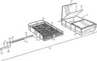
- FIG. 1shows an exploded view of an embodiment of the hitch-mounted cargo carrier.
- FIG. 2shows a perspective view of an embodiment of the hitch-mounted cargo carrier.
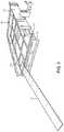
- FIG. 3shows a perspective view of an embodiment of the frame of the hitch-mounted cargo carrier.
- FIG. 4shows a perspective view of an embodiment of the hitch-mounted cargo carrier in use as a raised platform.
- FIG. 5shows a perspective view of an embodiment of the hitch-mounted cargo carrier affixed to a vehicle with one or more pieces of cargo secured on the upper surface of the lid members.
- a hitch-mounted cargo carrier 10comprises a container 11 , having a base 12 with a plurality of sidewalls extending therefrom. Each sidewall is flush against another sidewall, such that an enclosure having an interior 13 is formed therein, wherein the interior 13 is configured to hold cargo.
- the container 11further comprises a plurality of modular compartments configured to fit flush within the container 11 , such that each modular compartment is frictionally secured.
- the base 12is rectangular, such that the interior 13 forms a box.
- the container 11has two lateral sidewalls 15 that are disposed opposite one another and are equivalent in length.
- the container 11additionally comprises two longitudinal sidewalls 14 that are disposed opposite one another and perpendicular to the lateral sidewalls 15 , wherein the longitudinal sidewalls 14 are equivalent in length to one another and greater in length than the lateral sidewalls 15 .
- At least one lid member 17is affixed to an upper edge 16 of one of the plurality of sidewalls.
- there are two lid members 17wherein each lid member 17 is affixed to the upper edge 16 of one of the sidewalls such that each lid member 17 is affixed to a different sidewall.
- Each lid member 17is configured to affix overtop the container 11 , such that the total surface area of all lid members 17 are configured to be equivalent to the surface area of the base 12 , such that the lid members 17 fully enclose the interior volume 13 .
- each lid member 17is hingedly affixed to the upper edge 16 of the sidewall, such that each lid member 17 is configured to rotate around the upper edge 16 to rest flush against an outer surface of the container 11 .
- Thisallows a user to access the interior volume 13 from any side of the container 11 while allowing each lid member 17 to remain affixed to the container 11 such that the lid members 17 are not misplaced.
- each lid member 17is removably affixed to the upper edge 16 via a fastener, such as a clip or a latch, such that the lid member 17 can be completely removed. This allows a user to access the interior volume 13 when the container 11 is in an area where there is not enough space to allow the lid members 17 to open via rotation.
- the two lid members 17are each disposed on each of the lateral sidewalls 15 , such that they are opposing one another and configured to rotate away from one another when opened.
- each lid member 17is affixed to a varying sidewall, such that in one embodiment both lid members 17 are disposed proximally to one another on one of the longitudinal sidewalls 14 , whereas in another embodiment each lid member 17 is disposed on each of the longitudinal sidewalls 14 , such that the lid members 17 are offset from one another and disposed diagonally so as not to interfere with one another when rotating open or closed.
- Each lid member 17has an upper surface 19 and a lower surface.
- the upper surface 19is planar, such that it is configured to support additional cargo thereon, such as a tarp or a bike rack.
- the upper surface 19 of each lid member 17comprises a raised flange 20 disposed about the perimeter of each lid member 17 configured to provide an additional aid when securing the cargo on the upper surface 19 of the lid member 17 , such that the objects are confined to the upper surface 19 .
- the flange 20has a plurality of apertures 21 disposed at even intervals, thereby allowing a user to tie down any cargo placed atop the upper surface 19 of the lid member 17 .
- each lid member 17has at least one extendable leg 23 disposed on the upper surface 19 .
- Each extendable leg 23is disposed in a casing 22 configured to hold the extendable leg 23 therein.
- Each casing 22has one or more apertures 24 that allow a user to lock the extendable leg 23 into place once it has been extended to a desired length.
- each extendable leg 23is disposed in a corner of the lid member 17 such that it rests flush against the upper surface 19 and extends along the longitudinal sidewall 14 parallel to the upper surface 19 of the container 11 .
- Each casing 22 and extendable leg 23 thereinis configured to rotate ninety degrees prior to extending. In this way, the user can rotate and extend each casing 22 and extendable leg 23 prior to opening and rotating each lid member 17 , thereby allowing the user to utilize the lower surface of each lid member 17 as a table supported by the extendable legs 23 .
- the container 11further comprises at least one secondary lid member 18 , wherein each lower lid member 18 is configured to rest flush against the lower surface of each lid member 17 .
- Each secondary lid member 18is sized to fit flush beneath the lid member 17 above it and is similarly affixed to the container beneath the lid members 17 within the interior 13 of the container 11 such that it does not interfere with the operation of the lid members 17 .
- the lower lid members 18are also hingedly affixed to the container 11 and are configured to act as a table surface when the lid members 17 are rotated away from the container 11 .
- the hitch-mounted cargo carrier 10further comprises a frame 25 , configured to removably receive and support the container 11 .
- the frame 25is rectangularly shaped in the illustrated embodiment, having two lateral sides and two longitudinal sides disposed similarly to the container 11 . Additionally, the frame 25 is configured to support larger cargo therein that may otherwise not fit inside the container 11 , such as a small riding mower.
- the frame 25has a support bar 26 disposed about a perimeter of the frame 25 , wherein the support bar 26 is configured to enclose a portion of a lower body of the container 11 and is sized to fit flush around a perimeter of the container 11 .
- the support bar 26extends upward to support the container 11 and prevent the container 11 from moving while disposed in the frame 25 .
- a support siding 27is additionally disposed along an outer surface of the support bar 26 on one or more sides of the frame 25 .
- the support siding 27is configured to provide greater support and stability to the container 11 when the container 11 is secured to the frame 25 .
- the support siding 27extends further up the side of the container 11 than the support bar 26 on the respective sides on which the support siding 27 is disposed.
- the support siding 27is disposed on two sides of the frame 25 , such that the support siding 27 is disposed on one lateral side of the frame 25 and one longitudinal side of the frame 25 .
- the support siding 27varies with respect to which specific sides of the frame 25 it is disposed thereon, such that the support siding 27 can be disposed on both lateral sides or both longitudinal sides of the frame 25 . Further, the support siding 27 can also vary with respect to the number of sides of the frame 25 on which it is disposed, such that the support siding 27 can be disposed on only one of the sides of the frame 25 or on three sides of the frame 25 or on all four sides of the frame 25 .
- the hitch-mounted cargo carrier 10further comprises a support rod 28 , having a first section 29 and a second section 30 removably secured to one another via an intermediate bar 31 .
- Each section of the support rod 28has a first end and a second end.
- the first end 291 of the first section 29is configured to removably secure to a trailer hitch.
- the second end 292 of the first section 29 of the support rod 28is secured into the intermediate bar 31 , as is the first end 301 of the second section 30 of the support rod 28 .
- the second section 30is permanently offset from the first section 29 when both are removably secured within the intermediate bar 31 , such that each section is disposed at a different vertical height.
- the height of the second section 30is changeable within the intermediate bar 31 , such that the height of the second section 30 is offset from the first section wherein the second section 30 is of equivalent or greater height than the height of the first section 29 .
- the height of the second section 30is adjustable up to a terminal end of the intermediate bar 31 .
- the second end 302 of the second section 30is configured to removably affix to a support casing 33 disposed on a lower surface of the frame 25 .
- the support casing 33is dimensioned to receive the second end 302 of the second section 30 of the support rod 28 therein.
- the second section 30 of the support rod 28is telescopic, such that a length of the second section 30 is adjustable, thereby allowing a user to control the distance of the container 11 from the intermediate bar 31 through a sliding section 32 .
- the first end 291 of the first section 29 of the support rod 28is configured to removably secure to a hitch on a back end of a vehicle.
- the adjustability of the height of the second section 30allows the user to freely change a height of the frame 25 and container 11 to ensure the height of the container 11 is offset from the hitch of the vehicle, thereby providing greater stability to the hitch-mounted cargo container 10 .
- FIG. 3there is shown a perspective view of an embodiment of the frame of the hitch-mounted cargo carrier.
- the support bar 26is pivotably secured to the frame 25 , such that the support bar 26 can be rotated.
- the pivotable support bar 26is held in place with a locking pin 261 .
- the locking pin 261is pulled, the support bar 26 is free to rotate about an axis of the frame 25 edge. In this way, the user is able to move cargo into the frame 25 without having to lift the cargo over the support bar 26 .
- the support siding 27is reinforced to support additional weight and is removably secured to at least one side of the perimeter of the frame 25 , such that the support siding 27 can be removed from the frame 25 and disposed elsewhere.
- the support siding 27has a tapered end 271 and a non-tapered end.
- the tapered end 271is configured to sit flush against the base of the frame 25 when the support siding 27 is rotated ninety degrees, such that the support siding 27 provides a planar surface sloped towards the ground, wherein the non-tapered end rests against the ground.
- the support siding 27is configured to act as a ramp, allowing a user to push cargo onto the frame 25 along the planar surface of the support siding 27 .
- FIG. 4there is shown a perspective view of an embodiment of the hitch-mounted cargo carrier in use as a raised platform.
- at least one housing 34having an opening at one end and sealed at an opposing end, is disposed on an outer surface 35 of the container.
- each longitudinal side of the containerhas two housings 34 disposed at even intervals thereon, wherein each housing 34 is disposed such that each opening is aligned with the base of the container.
- a support leg 36is slidably disposed within each housing 34 , wherein each support leg 36 is configured to extend out of the housing 34 from the open end and lock into place at a predetermined point.
- each housing 34has one or more apertures 37 configured to accept a locking pin therethrough, such that the user can choose between one or more heights when extending each support leg 36 .
- the containerfurther comprises a plurality of cylindrical casings 38 disposed along one or more corners of the container, wherein each cylindrical casing 38 has an opening 39 at one end and is sealed at an opposing end.
- the cylindrical casings 38are disposed such that the openings 39 are aligned with the upper surface of the container, and the cylindrical casings 38 are disposed on each of the corners of the container.
- Each cylindrical casing 38is configured to accept a pole 71 therein, such as from an umbrella or tent 72 . Thereby, a user can set up a tent 72 to cover the container by removably securing the pole 71 of the tent 72 within the cylindrical casing 38 .
- a usercan set up the container as a platform or table, wherein the container is supported by a plurality of the support legs 36 and extendable legs 23 while the tent 72 is secured overtop the container with the tent poles 71 disposed in the cylindrical casings 38 .
- FIG. 5there is shown a perspective view of an embodiment of the hitch-mounted cargo carrier affixed to a vehicle with one or more pieces of cargo secured on the upper surface of the lid members.
- a userwill affix the first end of the first section of the support rod 28 to a hitch disposed on the rear of a vehicle 70 .
- the second end of the first section of the support rod 28is then secured to the intermediate bar, and the first end of the second section of the support rod 28 is secured to the intermediate bar at an appropriate height, depending on the height of the vehicle 70 and the bumper 73 of the vehicle.
- the second end of the second section of the support rod 28is then secured to the lower surface of the frame.
- the container 11is disposed in the frame and the lid members are disposed overtop the container 11 , enclosing any objects therein.
- One or more objectssuch as a pair of bikes 74 , are secured on the upper surface of the container.
- the bikes 74are secured via wire 75 by utilizing the apertures 21 disposed on the flanged edge 20 of the lid members. In this way, a user can secure any number of objects in or on a cargo container that is easily affixable to a trailer hitch of a vehicle, thereby allowing the user to easily carry a greater number of objects while additionally transporting the objects outside the vehicle.
Landscapes
- Engineering & Computer Science (AREA)
- Mechanical Engineering (AREA)
- Fittings On The Vehicle Exterior For Carrying Loads, And Devices For Holding Or Mounting Articles (AREA)
Abstract
Description
Claims (17)
Priority Applications (1)
| Application Number | Priority Date | Filing Date | Title |
|---|---|---|---|
| US16/108,700US10688938B2 (en) | 2017-08-22 | 2018-08-22 | Hitch-mounted cargo carrier |
Applications Claiming Priority (2)
| Application Number | Priority Date | Filing Date | Title |
|---|---|---|---|
| US201762548439P | 2017-08-22 | 2017-08-22 | |
| US16/108,700US10688938B2 (en) | 2017-08-22 | 2018-08-22 | Hitch-mounted cargo carrier |
Publications (2)
| Publication Number | Publication Date |
|---|---|
| US20190061636A1 US20190061636A1 (en) | 2019-02-28 |
| US10688938B2true US10688938B2 (en) | 2020-06-23 |
Family
ID=65434791
Family Applications (1)
| Application Number | Title | Priority Date | Filing Date |
|---|---|---|---|
| US16/108,700Expired - Fee RelatedUS10688938B2 (en) | 2017-08-22 | 2018-08-22 | Hitch-mounted cargo carrier |
Country Status (1)
| Country | Link |
|---|---|
| US (1) | US10688938B2 (en) |
Cited By (2)
| Publication number | Priority date | Publication date | Assignee | Title |
|---|---|---|---|---|
| US11332948B2 (en)* | 2018-01-23 | 2022-05-17 | KOKO Sports Management, LLC | Arena apparatus and methods of using and constructing same |
| US20240140324A1 (en)* | 2022-04-14 | 2024-05-02 | Hill Ready, Llc | Rear mounted bike rack for automobiles |
Families Citing this family (3)
| Publication number | Priority date | Publication date | Assignee | Title |
|---|---|---|---|---|
| US11040668B2 (en)* | 2019-08-15 | 2021-06-22 | Steven John Schmidt | Hitch mounted double deck cargo carrier for a vehicle |
| IL269564B2 (en) | 2019-09-23 | 2023-11-01 | Keter Home & Garden Products Ltd | Sawhorse |
| USD1021752S1 (en)* | 2022-10-31 | 2024-04-09 | Zhongshan Minghui Hardware Co., Ltd. | Hitch mount cargo carrier |
Citations (31)
| Publication number | Priority date | Publication date | Assignee | Title |
|---|---|---|---|---|
| US3582131A (en)* | 1969-03-21 | 1971-06-01 | Alan J Brown | Collapsible trailer |
| US4014586A (en)* | 1975-06-26 | 1977-03-29 | Engineering Concepts, Inc. | Combined trailer-camper unit |
| US4126324A (en)* | 1976-11-15 | 1978-11-21 | Browning Willard A | Collapsible trailer |
| US4372568A (en) | 1980-10-20 | 1983-02-08 | Spare Trunk Corporation | Luggage and accessory trailer |
| US4758008A (en)* | 1985-07-08 | 1988-07-19 | Albertus Moddejonge | Folding trailer |
| US4824163A (en)* | 1988-03-15 | 1989-04-25 | Jaroslav Hendrych | Convertible cover |
| US5249821A (en)* | 1991-01-26 | 1993-10-05 | John Raymond Evans | Trailer capable of being dismantled to readily storable condition |
| US5375902A (en)* | 1993-08-17 | 1994-12-27 | Church; James T. | Foldable mobile camper |
| US5524383A (en)* | 1995-03-20 | 1996-06-11 | Sanko; Paul J. | Disassembleable portable cold frame apparatus |
| US5595414A (en)* | 1994-10-13 | 1997-01-21 | Dulnig; Nikolai A. | Trailer that transforms into platform |
| US5761854A (en)* | 1993-07-19 | 1998-06-09 | Weatherhaven Resources, Ltd. | Collapsible portable containerized shelter |
| US6217106B1 (en)* | 1998-09-30 | 2001-04-17 | Fleetwood Folding Trailers, Inc. | Folding trailer with expandable bed assembly |
| US6283537B1 (en)* | 1997-07-09 | 2001-09-04 | Devore, Iii Phillip A. | Multifunction trailer |
| US6446997B1 (en)* | 2000-12-04 | 2002-09-10 | Walter F. Bergman | Trailer for transporting an inflated raft and related equipment |
| US20030173758A1 (en)* | 2002-03-14 | 2003-09-18 | Badger William A. | Tent assembly for use with utility trailers and vehicles |
| US6739617B1 (en)* | 2002-06-14 | 2004-05-25 | Arne L. Martin | Expandable trailer |
| US6962370B2 (en)* | 2002-04-05 | 2005-11-08 | Tricam International, Inc. | Collapsible utility trailer |
| US7073816B1 (en)* | 2003-10-22 | 2006-07-11 | Hiniker Company | Multi-use trailer |
| US20060158000A1 (en)* | 2004-11-29 | 2006-07-20 | Warlick Arthur G Iii | Sliding storage compartment |
| US7144070B2 (en) | 2005-01-07 | 2006-12-05 | Michael Wiebe | Combination multipurpose trailer and rooftop storage container and method therefor |
| US7156273B2 (en) | 2003-10-31 | 2007-01-02 | Morris Daniel W | Convertible cargo container system |
| US7165779B2 (en)* | 2002-03-27 | 2007-01-23 | Badger John T | Convertible combination utility/camper tow trailer |
| US7677592B2 (en)* | 2005-02-25 | 2010-03-16 | Stephen Giesler | Bicycle pod transport system |
| US20110221168A1 (en)* | 2010-03-10 | 2011-09-15 | John Alexander | Foldable Trailer |
| US8061571B2 (en) | 2007-03-28 | 2011-11-22 | Martin Aghajanian | Collapsible trailer container |
| US8240732B2 (en) | 2008-06-09 | 2012-08-14 | Cequent Consumer Products | Trailer utility box |
| US9718411B2 (en)* | 2015-06-17 | 2017-08-01 | Richard Doak Field, JR. | Tailgating trailer hitch assembly |
| US9932078B1 (en)* | 2016-09-30 | 2018-04-03 | Karavan Trailers, Inc. | Utility trailer |
| US20180178703A1 (en)* | 2016-12-27 | 2018-06-28 | Theodore J. Keck | Hitch-mounted carrier system with ramp |
| US10206495B2 (en)* | 2016-03-25 | 2019-02-19 | David Garside Smith | Vehicle receiver hitch-supported cargo rack transformable into a picnic table with benches |
| US20190193641A1 (en)* | 2017-12-06 | 2019-06-27 | Octavio I. Garza, JR. | Fisherman's Gear Box |
- 2018
- 2018-08-22USUS16/108,700patent/US10688938B2/ennot_activeExpired - Fee Related
Patent Citations (32)
| Publication number | Priority date | Publication date | Assignee | Title |
|---|---|---|---|---|
| US3582131A (en)* | 1969-03-21 | 1971-06-01 | Alan J Brown | Collapsible trailer |
| US4014586A (en)* | 1975-06-26 | 1977-03-29 | Engineering Concepts, Inc. | Combined trailer-camper unit |
| US4126324A (en)* | 1976-11-15 | 1978-11-21 | Browning Willard A | Collapsible trailer |
| US4372568A (en) | 1980-10-20 | 1983-02-08 | Spare Trunk Corporation | Luggage and accessory trailer |
| US4758008A (en)* | 1985-07-08 | 1988-07-19 | Albertus Moddejonge | Folding trailer |
| US4824163A (en)* | 1988-03-15 | 1989-04-25 | Jaroslav Hendrych | Convertible cover |
| US5249821A (en)* | 1991-01-26 | 1993-10-05 | John Raymond Evans | Trailer capable of being dismantled to readily storable condition |
| US5761854A (en)* | 1993-07-19 | 1998-06-09 | Weatherhaven Resources, Ltd. | Collapsible portable containerized shelter |
| US5375902A (en)* | 1993-08-17 | 1994-12-27 | Church; James T. | Foldable mobile camper |
| US5595414A (en)* | 1994-10-13 | 1997-01-21 | Dulnig; Nikolai A. | Trailer that transforms into platform |
| US5524383A (en)* | 1995-03-20 | 1996-06-11 | Sanko; Paul J. | Disassembleable portable cold frame apparatus |
| US6283537B1 (en)* | 1997-07-09 | 2001-09-04 | Devore, Iii Phillip A. | Multifunction trailer |
| US6217106B1 (en)* | 1998-09-30 | 2001-04-17 | Fleetwood Folding Trailers, Inc. | Folding trailer with expandable bed assembly |
| US6446997B1 (en)* | 2000-12-04 | 2002-09-10 | Walter F. Bergman | Trailer for transporting an inflated raft and related equipment |
| US20030173758A1 (en)* | 2002-03-14 | 2003-09-18 | Badger William A. | Tent assembly for use with utility trailers and vehicles |
| US7159893B2 (en)* | 2002-03-14 | 2007-01-09 | Jumping Jack, Inc. | Tent assembly for use with utility trailers and vehicles |
| US7165779B2 (en)* | 2002-03-27 | 2007-01-23 | Badger John T | Convertible combination utility/camper tow trailer |
| US6962370B2 (en)* | 2002-04-05 | 2005-11-08 | Tricam International, Inc. | Collapsible utility trailer |
| US6739617B1 (en)* | 2002-06-14 | 2004-05-25 | Arne L. Martin | Expandable trailer |
| US7073816B1 (en)* | 2003-10-22 | 2006-07-11 | Hiniker Company | Multi-use trailer |
| US7156273B2 (en) | 2003-10-31 | 2007-01-02 | Morris Daniel W | Convertible cargo container system |
| US20060158000A1 (en)* | 2004-11-29 | 2006-07-20 | Warlick Arthur G Iii | Sliding storage compartment |
| US7144070B2 (en) | 2005-01-07 | 2006-12-05 | Michael Wiebe | Combination multipurpose trailer and rooftop storage container and method therefor |
| US7677592B2 (en)* | 2005-02-25 | 2010-03-16 | Stephen Giesler | Bicycle pod transport system |
| US8061571B2 (en) | 2007-03-28 | 2011-11-22 | Martin Aghajanian | Collapsible trailer container |
| US8240732B2 (en) | 2008-06-09 | 2012-08-14 | Cequent Consumer Products | Trailer utility box |
| US20110221168A1 (en)* | 2010-03-10 | 2011-09-15 | John Alexander | Foldable Trailer |
| US9718411B2 (en)* | 2015-06-17 | 2017-08-01 | Richard Doak Field, JR. | Tailgating trailer hitch assembly |
| US10206495B2 (en)* | 2016-03-25 | 2019-02-19 | David Garside Smith | Vehicle receiver hitch-supported cargo rack transformable into a picnic table with benches |
| US9932078B1 (en)* | 2016-09-30 | 2018-04-03 | Karavan Trailers, Inc. | Utility trailer |
| US20180178703A1 (en)* | 2016-12-27 | 2018-06-28 | Theodore J. Keck | Hitch-mounted carrier system with ramp |
| US20190193641A1 (en)* | 2017-12-06 | 2019-06-27 | Octavio I. Garza, JR. | Fisherman's Gear Box |
Cited By (3)
| Publication number | Priority date | Publication date | Assignee | Title |
|---|---|---|---|---|
| US11332948B2 (en)* | 2018-01-23 | 2022-05-17 | KOKO Sports Management, LLC | Arena apparatus and methods of using and constructing same |
| US12006722B2 (en) | 2018-01-23 | 2024-06-11 | Sensei Ltd. | Arena apparatus and methods of using and constructing same |
| US20240140324A1 (en)* | 2022-04-14 | 2024-05-02 | Hill Ready, Llc | Rear mounted bike rack for automobiles |
Also Published As
| Publication number | Publication date |
|---|---|
| US20190061636A1 (en) | 2019-02-28 |
Similar Documents
| Publication | Publication Date | Title |
|---|---|---|
| US10688938B2 (en) | Hitch-mounted cargo carrier | |
| US9101206B1 (en) | Folding table umbrella wagon | |
| US5653194A (en) | Collapsible portable animal crate | |
| US6575509B1 (en) | Extendable bumper for external vehicle transportation and storage | |
| US6926129B2 (en) | Rolling duffel bag | |
| USRE44454E1 (en) | Collapsible trailer container | |
| US10065304B2 (en) | Case | |
| US6045172A (en) | Pick-up truck bed extending device | |
| US5383703A (en) | Modular trailer | |
| US20080190977A1 (en) | Vehicle gate with interchangeable accessories | |
| US4195889A (en) | Camper box | |
| US6467433B1 (en) | Vehicle-mounted animal enclosure | |
| US20190283684A1 (en) | Collapsible folding truck trunk | |
| US20120223494A1 (en) | Storage Tote With Legs | |
| CN107616102A (en) | Multifunctional pet cage | |
| US11840385B2 (en) | Collapsible cargo utility box | |
| US6189945B1 (en) | Rack assembly for van | |
| US8393634B2 (en) | Easy access collapsible cart | |
| US20150048129A1 (en) | Modular truck bed storage system | |
| US3940175A (en) | Multi-purpose combination trailer and picnic table | |
| US10399505B1 (en) | Collapsable pickup truck storage compartment | |
| US10455915B2 (en) | Personal wheeled container exterior support shelf | |
| US6125772A (en) | Platform apparatus | |
| US5102180A (en) | Vehicle cover with sideways accessible storage container | |
| US9919658B1 (en) | Collapsible container assembly |
Legal Events
| Date | Code | Title | Description |
|---|---|---|---|
| FEPP | Fee payment procedure | Free format text:ENTITY STATUS SET TO UNDISCOUNTED (ORIGINAL EVENT CODE: BIG.); ENTITY STATUS OF PATENT OWNER: MICROENTITY | |
| FEPP | Fee payment procedure | Free format text:ENTITY STATUS SET TO SMALL (ORIGINAL EVENT CODE: SMAL); ENTITY STATUS OF PATENT OWNER: MICROENTITY Free format text:ENTITY STATUS SET TO MICRO (ORIGINAL EVENT CODE: MICR); ENTITY STATUS OF PATENT OWNER: MICROENTITY | |
| STPP | Information on status: patent application and granting procedure in general | Free format text:DOCKETED NEW CASE - READY FOR EXAMINATION | |
| STPP | Information on status: patent application and granting procedure in general | Free format text:NON FINAL ACTION MAILED | |
| STPP | Information on status: patent application and granting procedure in general | Free format text:NOTICE OF ALLOWANCE MAILED -- APPLICATION RECEIVED IN OFFICE OF PUBLICATIONS | |
| FEPP | Fee payment procedure | Free format text:ENTITY STATUS SET TO MICRO (ORIGINAL EVENT CODE: MICR); ENTITY STATUS OF PATENT OWNER: MICROENTITY | |
| STPP | Information on status: patent application and granting procedure in general | Free format text:PUBLICATIONS -- ISSUE FEE PAYMENT RECEIVED | |
| STCF | Information on status: patent grant | Free format text:PATENTED CASE | |
| FEPP | Fee payment procedure | Free format text:MAINTENANCE FEE REMINDER MAILED (ORIGINAL EVENT CODE: REM.); ENTITY STATUS OF PATENT OWNER: MICROENTITY | |
| LAPS | Lapse for failure to pay maintenance fees | Free format text:PATENT EXPIRED FOR FAILURE TO PAY MAINTENANCE FEES (ORIGINAL EVENT CODE: EXP.); ENTITY STATUS OF PATENT OWNER: MICROENTITY | |
| STCH | Information on status: patent discontinuation | Free format text:PATENT EXPIRED DUE TO NONPAYMENT OF MAINTENANCE FEES UNDER 37 CFR 1.362 | |
| FP | Lapsed due to failure to pay maintenance fee | Effective date:20240623 |