US10688226B2 - Canister lid and corresponding systems and methods - Google Patents
Canister lid and corresponding systems and methodsDownload PDFInfo
- Publication number
- US10688226B2 US10688226B2US15/437,232US201715437232AUS10688226B2US 10688226 B2US10688226 B2US 10688226B2US 201715437232 AUS201715437232 AUS 201715437232AUS 10688226 B2US10688226 B2US 10688226B2
- Authority
- US
- United States
- Prior art keywords
- canister
- lobe
- canister lid
- lid
- annular perimeter
- Prior art date
- Legal status (The legal status is an assumption and is not a legal conclusion. Google has not performed a legal analysis and makes no representation as to the accuracy of the status listed.)
- Active, expires
Links
Images


Classifications
- A61M1/0005—
- A—HUMAN NECESSITIES
- A61—MEDICAL OR VETERINARY SCIENCE; HYGIENE
- A61M—DEVICES FOR INTRODUCING MEDIA INTO, OR ONTO, THE BODY; DEVICES FOR TRANSDUCING BODY MEDIA OR FOR TAKING MEDIA FROM THE BODY; DEVICES FOR PRODUCING OR ENDING SLEEP OR STUPOR
- A61M1/00—Suction or pumping devices for medical purposes; Devices for carrying-off, for treatment of, or for carrying-over, body-liquids; Drainage systems
- A61M1/60—Containers for suction drainage, adapted to be used with an external suction source
- A61M1/604—Bag or liner in a rigid container, with suction applied to both
- A61M1/0001—
- A61M1/0017—
- A—HUMAN NECESSITIES
- A61—MEDICAL OR VETERINARY SCIENCE; HYGIENE
- A61M—DEVICES FOR INTRODUCING MEDIA INTO, OR ONTO, THE BODY; DEVICES FOR TRANSDUCING BODY MEDIA OR FOR TAKING MEDIA FROM THE BODY; DEVICES FOR PRODUCING OR ENDING SLEEP OR STUPOR
- A61M1/00—Suction or pumping devices for medical purposes; Devices for carrying-off, for treatment of, or for carrying-over, body-liquids; Drainage systems
- A61M1/60—Containers for suction drainage, adapted to be used with an external suction source
- A61M1/63—Containers for suction drainage, adapted to be used with an external suction source with means for emptying the suction container, e.g. by interrupting suction
Definitions
- This disclosurerelates generally to canister lids, and more particularly to suction canister lids.
- Fluid collection canistersare used to collect and dispose of fluids in a variety of medical procedures.
- Fluid collection canistershave evolved over the years. In the early twentieth century, fluid collection canisters were manufactured from glass. After a particular procedure, the glass canister was sterilized and reused. Sometime around the 1960's, plastic fluid collection canisters, such as those manufactured from polystyrene, began to replace glass canisters. The polystyrene canisters were disposable, thereby reducing the chance of a patient getting an infection or other malady as a result of improper sterilization.
- linerswere introduced. Rather than capturing fluid in the canister itself, fluids were captured in a disposable lining. The introduction of liners reduced both cost and the amount of waste.
- FIG. 1illustrates a perspective view of one explanatory canister lid in accordance with one or more embodiments of the disclosure.
- FIG. 2illustrates a top plan view of one explanatory canister lid in accordance with one or more embodiments of the disclosure.
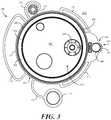
- FIG. 3illustrates a bottom plan view of one explanatory canister lid in accordance with one or more embodiments of the disclosure.
- FIG. 4illustrates a side elevation view of one explanatory canister lid in accordance with one or more embodiments of the disclosure.
- FIG. 5illustrates one explanatory canister suitable for use with an explanatory canister lid in accordance with one or more embodiments of the disclosure.
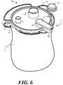
- FIG. 6illustrates a portion of one explanatory canister system in accordance with one or more embodiments of the disclosure.
- FIG. 7illustrates a sectional view of one explanatory canister system in accordance with one or more embodiments of the disclosure.
- a “substantially orthogonal” angle with a manufacturing tolerance of plus or minus two degreeswould include all angles between 88 and 92, inclusive.
- reference designators shown herein in parenthesisindicate components shown in a figure other than the one in discussion. For example, talking about a device ( 10 ) while discussing figure A would refer to an element, 10 , shown in figure other than figure A.
- the apparatus components shown belowhave been represented where appropriate by conventional symbols in the drawings, showing only those specific details that are pertinent to understanding the embodiments of the present disclosure so as not to obscure the disclosure with details that will be readily apparent to those of ordinary skill in the art having the benefit of the description herein.
- Embodiments of the disclosureprovide a canister lid that is suitable for use with a canister in fluid collection operations.
- canister lids configured in accordance with embodiments of the disclosureeliminate one or more of the tubes or hoses required with prior art systems. Not only does this reduce system complexity and cost, the elimination of a hose or tube makes use of fluid collection canisters equipped with canister lids configured in accordance with embodiments of the disclosure quicker and less complex as well.
- a canister lidincludes an annular perimeter surrounding an interior portion, which may be planar, convex, or concave.
- the canister lidincludes a suction conduit extending from a perimeter of the canister lid.
- the suction conduitinterrupts the annular perimeter with a portion of the suction duct that extends distally away from the annular perimeter.
- the suction conduitincludes a suction duct that separates a first lobe and a second lobe, each of which is semicircular in one or more embodiments.
- the suction ductdefines a frustoconical shape. This results in the first semicircular lobe, the frustoconical suction duct, and the second semicircular lobe defining a tapered stadium shape when viewed in plan view.
- the suction ductseparates the first lobe and the second lobe and traverses or intersects the annular perimeter such that the first lobe is disposed interior of the annular perimeter while the second lobe is disposed exterior to the annular perimeter.
- the second lobeis operable to engage a suction port extending distally from the sidewall of a canister when the annular perimeter engages the lip of the canister.
- aircan flow from the second lobe through the suction duct to the first lobe, or vice versa, such that the suction conduit serves as either a suction input or an exhaust. This eliminates the need for at least one tube or hose in fluid collection operations.
- FIGS. 1-4illustrated therein is one embodiment of a canister lid 100 configured in accordance with one or more embodiments of the disclosure.
- FIG. 1illustrates a top perspective view of the canister lid 100
- FIG. 2illustrates a top plan view of the canister lid 100
- FIG. 3illustrates a bottom plan view of the canister lid 100
- FIG. 4illustrates a side elevation view of the canister lid 100 .
- the canister lid 100can be manufactured from a thermoplastic material by way of an injection molding process.
- the canister lid 100is manufactured from polypropylene.
- the canister lid 100is manufactured from polyethylene. It will be obvious to those of ordinary skill in the art having the benefit of this disclosure that other suitable semi-rigid materials may be substituted for the thermoplastic. Further, other manufacturing processes may be used to fabricate the canister lid 100 as well.
- the canister lid 100includes an annular perimeter 101 surrounding an interior portion 102 .
- the annular perimeter 101defines a substantially circular (when viewed in plan view) sidewall surrounding the interior portion 102 .
- the annular perimeter 101is operable as a “canister connector” in that it is configured to connect to a canister, one example of which is a fluid collection canister.
- the canister lid 100also includes a suction conduit 103 .
- the suction conduit 103comprises a suction duct 104 , a first lobe 105 , and a second lobe 106 .
- the suction conduit 103instead interrupts the annular perimeter 101 . As best shown in FIG.
- the suction duct 104 separating the first lobe 105 and the second lobe 106traverses or intersects the annular perimeter 101 such that the first lobe 105 is disposed interior of the annular perimeter 101 along the interior portion 102 of the canister lid 100 , while the second lobe 106 is disposed exterior to, and extends distally away from an outer edge of, the annular perimeter 101 .
- the first lobe 105 and the second lobe 106are substantially semicircular. While they can be the same, in one or more embodiments the radii of the first lobe 105 and the second lobe 106 are different. In the illustrative embodiment of FIGS. 1-4 , the radius of the second lobe 106 is less than that of the first lobe. To connect the first lobe 105 with the second lobe 106 , this results in the suction duct 104 being tapering or frustoconical when viewed in plan view. Accordingly, in such an embodiment when the suction conduit is viewed in plan view, the suction conduit can resemble a tapered stadium shape.
- a “stadium shape”is a geometric figure consisting of a rectangle with common top and bottom lengths, but where the normally orthogonal ends are replaced with semicircles having a common radius.
- the perimeter of the stadium shaperesembles a conventional football stadium.
- a “tapered stadium shape”occurs where the radius of one semicircle is less than the other. Rather than the connecting sides being parallel, they then become tapered. They thus are frustoconical, which means that they have the shape of a frustum of a cone.
- a frustoconical shapeis the shape of a cone if the narrow end, or tip, has been cut off.
- the center of the “tapered stadium shape” of the suction conduit 103bisects the annular perimeter 101 with half of the tapered stadium shape, i.e., the second lobe 106 and a portion of the suction duct 104 , extending outwardly away from an outer side of the annular perimeter 101 while another half of the tapered stadium shape, i.e., the first lobe 105 and another portion of the suction duct 104 , are inside the annular perimeter 101 and traverse the interior portion 102 of the canister lid 100 .
- the suction conduit 103is hollow on the inside such that air or other fluid can be drawn through each of the first lobe 105 , the suction duct 104 , and the second lobe 106 .
- the bottom side of the canister lid 100includes a first aperture 305 disposed under the first lobe ( 105 ).
- the first lobe 105 and the second lobe 106serve as chamber walls for the first aperture 305 and the second aperture 306 , respectively.
- the suction duct 104includes a hollow duct 307 and connects these two chambers, air and other fluids can flow into the first aperture 305 , through the first lobe 105 , through the hollow duct 307 of the suction duct 104 , into the second lobe 106 , and out of the second aperture 306 , or vice versa.
- the inclusion of the suction conduit 103advantageously allows for the elimination of a hose that would traditionally be used to remove air from, or deliver air to, a suction canister.
- the first lobe 105comprises a first lobe annular wall 107 .
- the second lobe 106comprises a second lobe annular wall 108 .
- the suction duct 104can include one or more suction duct sidewalls 109 that connect the first lobe annular wall 107 and the second lobe annular wall 108 .
- the suction duct sidewalls 109are non-parallel, and taper as they extend from the first lobe annular wall 107 to the second lobe annular wall 108 .
- first lobe annular wall 107 and the second lobe annular wall 108are substantially semicircular.
- other shapescan be substituted for the generally semicircular first lobe annular wall 107 and second lobe annular wall 108 .
- These sidewallscould alternatively be rectangular, triangular, take free form shapes, or be ovular, pentagonal, hexagonal, and so forth.
- Other shapes and configurations for the first lobe annular wall 107 and the second lobe annular wall 108will be obvious to those of ordinary skill in the art having the benefit of this disclosure.
- the first lobe annular wall 107is greater in circumference than is the second lobe annular wall 108 .
- the second lobe annular wall 108may have a greater perimeter than the first lobe annular wall 107 .
- the first lobe annular wall 107 and the second lobe annular wall 108will have substantially equal perimeters, which would result in a conventional stadium shape.
- the annular perimeter 101 of the canister lid 100is operable to connect to the lip edge of a canister. When this occurs, the interior portion 102 spans and essentially seals the opening of the canister. Embodiments of the canister will be shown in subsequent figures.
- the canister lid 100also includes one or more ports 110 , 111 extending from the interior portion 102 . The one or more ports 110 , 111 facilitate the transport of fluids, be they air, liquids, or other fluids, into and away from the canister.
- the canister lid 100includes two ports 110 , 111 .
- the canister lid 100can be thought of as having a top side 112 and a “canister engaging side” 312 .
- the top side 112is shown in plan view in FIG. 2
- the canister engaging side 312is shown in plan view in FIG. 3 .
- the top side 112is the side exposed to the environment when the canister lid 100 is coupled to a canister.
- the canister engaging side 312engages the canister and correspondingly is oriented toward the interior of the canister when the canister lid 100 seals the canister.
- each of the ports 110 , 111extends distally from the interior portion 102 from the top side 112 .
- the first aperture 305 disposed beneath the first lobe 105 and the second aperture 306 disposed beneath the second lobe 106are each disposed on the canister engaging side 312 .
- the one or more ports 110 , 111facilitate fluid collection and transport to and from a canister to which the canister lid 100 is coupled. While the ports can be arranged in any number of ways, and can accommodate any number of functions, in one embodiment a first port 111 comprises a suction port while a second port 110 comprises a pour spout.
- a tube or hosecan be coupled to the suction port.
- a vacuum or other suction applianceis then coupled to the second aperture 306 disposed beneath the second lobe 106 .
- the tube or hose coupled to the suction portcan then coupled to a hand-held suction device.
- the vacuum or suction applianceWhen the vacuum or suction appliance is actuated, the vacuum draws air from the canister through the first aperture 305 disposed beneath the first lobe 105 , through the suction duct 104 , through the second lobe 106 and out the second aperture 306 . This causes fluid to be drawn through the hand-held suction device into the suction port and into the canister to which the canister lid 100 is coupled. Fluid can be prevented from entering the vacuum or suction device by way of a filter (not shown) placed beneath the first aperture 305 disposed beneath the first lobe 105 .
- the suction portcan alternatively be used as a tandem port.
- a tandem portis a port that can be used to daisy chain fluid collection canisters together. For example, in some medical procedures, it will be anticipated that more fluid will be collected than can be stored in a single fluid collection canister. In such situations, it may be necessary to couple multiple fluid collection canisters together with a tandem port, such that when one gets full, fluid can be delivered to other, empty fluid collection canisters.
- the pour spoutcan be used for a variety of purposes. Illustrating by example, in one or more embodiments the pour spout can be used for pouring solidifier into a filled canister after drawing fluids into the canister. The solidifier agglutinates the fluid, thereby making it easy to transport or dispose. In alternate embodiments, the pour spout can be used to pour fluids out of the canister.
- ports not in usecan be sealed with one or more caps 113 , 114 that are integrally tethered, in this illustrative embodiment, to the canister lid 100 by a corresponding tab 115 , 116 .
- caps 113 , 114are to cover the one or more ports 110 , 111 on a one-to-one basis.
- cap 113is convex up, meaning that when it is inverted 180 degrees it becomes a female receiver for the first port 111 .
- cap 114is concave up, which means that when it is inverted 180 degrees, it becomes a male insert for the second port 110 .
- each cap 113 , 114is tethered directly to an exterior wall of the annular perimeter 101 by a corresponding tab 115 , 116 that is integrally formed with, and extends distally away from, the exterior wall of the annular perimeter 101 .
- each tab 115 , 116is straight and extends substantially orthogonally away from the annular perimeter 101 .
- each tab 115 , 116is arcuate, having a radius less than the annular perimeter 101 . In other embodiments, one tab 115 will be arcuate, while the other tab 116 is linear, and vice versa.
- the ports 110 , 111can be disposed in various locations across the interior portion 102 of the canister lid 100 , in one embodiment the ports 110 , 111 and the first lobe 105 of the suction conduit 103 are roughly evenly spaced around the interior portion 102 .
- the first lobe 105 , the pour spout, i.e., port 110 , and the suction port, i.e., port 111are each radially separated 201 by about 120 degrees along the interior portion 102 .
- first lobe 105being roughly at the “three o'clock” position when the suction conduit 103 is oriented at the right of the canister lid 100 , while port 111 is roughly at the eleven o'clock position and port 110 is roughly at the seven o'clock position.
- Arranging the first lobe 105 and one or more ports 110 , 111 in this orientationoffers maximum separation from each element about the interior portion 102 of the canister lid 100 .
- the one or more ports 110 , 111extend distally from the top side 112 of the interior portion 102 of the canister lid 100 .
- each of the one or more ports 110 , 111extends to a common height from the interior portion 102 of the canister lid 100 .
- the one or more ports 110 , 111extend to different heights from the interior portion 102 of the canister lid.
- port 110extends distally away from the interior portion 102 farther than does port 111 . Accordingly, where port 111 is a suction port and port 110 is a pour spout, port 110 can extend farther from the interior portion 102 to facilitate easier pouring of fluids from a container coupled to the canister lid 100 .
- the annular perimeter 101defines a canister lip engaging recess 301 open to the canister engaging side 312 of the canister lid 100 .
- the canister lip engaging recess 301comprises a first annular wall 302 , a second annular wall 304 , and a bridge 303 spanning the first annular wall 302 and the second annular wall 304 .
- the second annular wall 304comprises an exterior wall of both the canister lid 100 and the annular perimeter 101 .
- the bridge 303is oriented substantially orthogonally with both the first annular wall 302 and the second annular wall 304 .
- the canister lip engaging recess 301can include mechanical features for engaging the lip edge of a canister. Examples of these mechanical features include mechanical locks, snaps, and the like.
- the canister lip engaging recess 301can include threads so as to be screwed onto a canister to form a hermetic seal.
- the second annular wall 304can include an inclined plane disposed along an interior portion of the second annular wall 304 that defines a thread. Alternatively, a dual thread can be used.
- Other attachment mechanisms suitable for use in the canister lip engaging recess 301will be obvious to those of ordinary skill in the art having the benefit of this disclosure.
- each of the one or more of ports 110 , 111extends distally from the interior portion 102 by a height that exceeds a height of the annular perimeter 101 .
- a height of the first annular wall 302 to the top side 112 from the interior portion 102is less than a height of either of the one or more ports 110 , 111 as best shown in FIG. 4 .
- one or more arcuate handles 117 , 118 , 119are included.
- the one or more arcuate handlescomprise at least two arcuate handles 117 , 118 , with each arcuate handle 117 , 118 being separated from the annular perimeter 101 except at a first end and a second end, and wrapping radially about a common center with an exterior wall of the annular perimeter 101 .
- the one or more arcuate handlescomprise three arcuate handles 117 , 118 , 119 .
- a first arcuate handle 119coupled to the annular perimeter 101 at two ends, and has a greater radius than either of the other two arcuate handles 117 , 118 .
- each of a second arcuate handle 117 and a third arcuate handle 118are coupled between the annular perimeter 101 and the second lobe 106 of the suction conduit 103 .
- each arcuate handle 117 , 118 , 119comprises a substantially planar element separated from the annular perimeter 101 except at the first end and the second end.
- each arcuate handle 117 , 118 , 119is not only separated from the annular perimeter except at the first end and the second end, but additionally wraps radially about a common center with the exterior wall of the annular perimeter 101 .
- the amount that the arcuate handles 117 , 118 , 119 wrap about the annular perimeter 101can vary based upon design choice and application. For example, while arcuate handle 119 is shown has having a greater radius than either arcuate handle 117 or acruate handle 118 , the opposite could also be true. Additionally, the arcuate handles 117 , 118 , 119 could all have different radii as well.
- a usercan grasp one or more of the arcuate handles 117 , 118 , 119 to remove the canister lid 100 from a canister. In one embodiment, only one arcuate handle will be included. In other embodiments, two or more arcuate handles are included. In still other embodiments, three or more arcuate handles are included. Other configurations will be obvious to those of ordinary skill in the art having the benefit of this disclosure.
- the canister lid 100is manufactured as a unitary, singular, integrated part where, for example, the annular perimeter 101 , interior portion 102 , ports 110 , 111 , suction conduit 103 , caps 113 , 114 , tabs 115 , 116 , and arcuate handles 117 , 118 , 119 comprise a single part.
- FIG. 5illustrated therein is one illustrative canister 500 suitable for use with a canister lid ( 100 ) configured in accordance with one or more embodiments of the disclosure.
- Canisters suitable for use with embodiments of the disclosurecan be manufactured in different sizes.
- the canister 500is a 2400 cc canister.
- the canister 500is a 1500 cc canister.
- the canister 500is manufactured from a clear, substantially rigid thermoplastic by way of an injection molding process.
- the canister 500is manufactured from clear polystyrene, which is also known sometimes by the name “crystal styrene.”
- the canisterincludes a rim 501 , which may include a lip 502 or other mating feature that is suitable for coupling to or otherwise engaging a canister lip engaging recess ( 201 ) of a canister lid ( 100 ).
- the canisterincludes a cylindrical sidewall 503 that extends from a base 504 .
- the cylindrical sidewall 503is substantially orthogonal relative to the base 504 .
- the cylindrical sidewall 503is modestly tapered, such as by two degrees.
- the canister 500can include tapered sidewalls that extend distally from the base 504 to the rim 501 with an outward flare.
- Tapered sidewallshelp facilitate release of the canister 500 both from stacked configurations with other canisters and from a mold, where the canister 500 can be manufactured by injection molding.
- the lip 502extends outwardly from the cylindrical sidewall 503 .
- the canister 500also includes an exterior suction assembly 505 .
- the exterior suction assemblyincludes a suction port 506 extending distally from the cylindrical sidewall 503 on a mechanical support 507 that allows the suction port 506 to attach to a central vacuum or suction apparatus in a hospital or other medical facility.
- the “overhanging dog bone” of the second lobe ( 106 ) extending from the annular perimeter ( 101 ) of a canister lid ( 100 )configured in accordance with one or more embodiments of the disclosure allows this suction port 506 to draw air through the suction conduit ( 103 ) from the interior 508 of the canister 500 .
- the second lobe ( 106 )is to engage the suction port 506 when the canister lip engaging recess ( 301 ) of the annular perimeter ( 101 ) of a canister lid ( 100 ) engages the lip 502 of the canister 500 . This will be shown in more detail in FIG. 7 below.
- the portion 600 of the canister systemincludes the canister lid 100 of FIGS. 1-4 , which can be attached to the canister ( 500 ) of FIG. 5 .
- Attached to the canister lid 100 in this embodimentis a disposable liner 601 operable to catch fluids or other materials drawn in through the suction port.
- the canister lid 100is manufactured as a unitary, singular, integrated part where, for example, the annular perimeter 101 , interior portion 102 , ports 110 , 111 , suction conduit 103 , caps 113 , 114 , tabs 115 , 116 , and arcuate handles 117 , 118 , 119 comprise a single part.
- the suction conduit 103comprises a separate suction conduit cap 602 coupled to each of the first lobe annular wall 107 , the second lobe annular wall 108 , and the one or more suction duct sidewalls 109 .
- the suction conduit cap 602can be adhesively sealed to each of the first lobe annular wall 107 , the second lobe annular wall 108 , and the one or more suction duct sidewalls 109 in one embodiment.
- the suction conduit cap 602can be thermally or ultrasonically welded to each of the first lobe annular wall 107 , the second lobe annular wall 108 , and the one or more suction duct sidewalls 109 in other embodiments.
- FIG. 7illustrated therein is a sectional view, taken along the sectional line shown in FIG. 2 , of an assembled canister system 700 once the canister lid 100 has been attached to the lip 502 of the canister 500 .
- the second annular wall 304 of the annular perimeter 101can include one or more compliant coupling members to attach to the lip 502 of the canister 500 .
- the second annular wall 304 of the annular perimeter 101can also be configured as cantilevered member operable to “clamp” the second annular wall 304 of the canister lid 100 to the lip 502 of the canister 500 .
- the second lobe 106engages the suction port 506 of the canister 500 when the annular perimeter 101 of the canister lid 100 engages the lip 502 of the canister 500 .
- the interior portion 102 of the canister lid 100defines a convex surface 701 toward the container engaging side 312 of the canister lid 100 .
- the interior portion 102is shown spanning an interior of the annular perimeter 101 . This convex surface 701 can be advantageous when the pressure within the canister 500 is less than outside the canister 500 .
- the convex surface 701works as a mechanical buttress to improve the seal between the canister lid 100 and canister 500 .
- the convex surface 701is pushed outward, the second annular wall 304 of the annular perimeter 101 is pushed inward against the lip 502 of the canister 500 , thereby increasing the integrity of the seal therebetween.
- the convex surface 701is configured to extend from the first annular wall 302 of the annular perimeter 101 towards the canister engaging side 312 of the canister lid 100 . Said differently, as viewed in FIG. 7 , the convex surface 701 points downward, or toward the canister engaging side 312 . In one embodiment, the portions of the interior portion 102 defining the sides of the convex surface 701 extend from the first annular wall 302 of the annular perimeter at an angle between ninety-five and one hundred and five degrees. This results in a convex surface 701 shape that is between three and ten millimeters in depth.
- barrier wall 702extending from the interior portion 102 distally toward the canister engaging side 312 of the canister lid 100 .
- the barrier wall 702is to engage the disposable liner 601 to ensure that no fluids pass outside the disposable liner into the interior portion of the canister 500 disposed between the disposable liner 601 and the cylindrical sidewall 503 .
- the orientation of the one or more ports 110 ,( 111 )can also be seen in the sectional view of FIG. 7 .
- a major axis 703 of the one or more ports 110 ,( 111 )is oriented substantially parallel with the barrier wall 702 .
- the major axis 703 of the one or more ports 110 ,( 111 )can be oriented orthogonally with the barrier wall 702 as taught in commonly assigned U.S. patent application Ser. No. 12/769,900, filed Apr. 29, 2010.
- the major axis 703 of the one or more ports 110 ,( 111 )can be oriented skew with the barrier wall 702 .
- Other configurationswill be obvious to those of ordinary skill in the art having the benefit of this disclosure.
Landscapes
- Health & Medical Sciences (AREA)
- Heart & Thoracic Surgery (AREA)
- Engineering & Computer Science (AREA)
- Hematology (AREA)
- Anesthesiology (AREA)
- Biomedical Technology (AREA)
- Vascular Medicine (AREA)
- Life Sciences & Earth Sciences (AREA)
- Animal Behavior & Ethology (AREA)
- General Health & Medical Sciences (AREA)
- Public Health (AREA)
- Veterinary Medicine (AREA)
- External Artificial Organs (AREA)
- Mechanical Engineering (AREA)
Abstract
Description
Claims (20)
Priority Applications (1)
| Application Number | Priority Date | Filing Date | Title |
|---|---|---|---|
| US15/437,232US10688226B2 (en) | 2016-01-25 | 2017-02-20 | Canister lid and corresponding systems and methods |
Applications Claiming Priority (2)
| Application Number | Priority Date | Filing Date | Title |
|---|---|---|---|
| US15/005,741US10398807B2 (en) | 2016-01-25 | 2016-01-25 | Canister lid and corresponding systems and methods |
| US15/437,232US10688226B2 (en) | 2016-01-25 | 2017-02-20 | Canister lid and corresponding systems and methods |
Related Parent Applications (1)
| Application Number | Title | Priority Date | Filing Date |
|---|---|---|---|
| US15/005,741Continuation-In-PartUS10398807B2 (en) | 2016-01-25 | 2016-01-25 | Canister lid and corresponding systems and methods |
Publications (2)
| Publication Number | Publication Date |
|---|---|
| US20170209629A1 US20170209629A1 (en) | 2017-07-27 |
| US10688226B2true US10688226B2 (en) | 2020-06-23 |
Family
ID=59360093
Family Applications (1)
| Application Number | Title | Priority Date | Filing Date |
|---|---|---|---|
| US15/437,232Active2036-12-18US10688226B2 (en) | 2016-01-25 | 2017-02-20 | Canister lid and corresponding systems and methods |
Country Status (1)
| Country | Link |
|---|---|
| US (1) | US10688226B2 (en) |
Citations (55)
| Publication number | Priority date | Publication date | Assignee | Title |
|---|---|---|---|---|
| US3814098A (en) | 1971-12-08 | 1974-06-04 | Deaton Medical Co | Medical suction apparatus |
| US3866608A (en) | 1973-10-23 | 1975-02-18 | Sorenson Research Co | Aseptic suction collection system and method |
| US4321922A (en) | 1980-01-21 | 1982-03-30 | Deaton David W | Medical receptacle with disposable liner assembly |
| US4379455A (en) | 1980-01-21 | 1983-04-12 | Deaton David W | Medical receptacle with disposable liner assembly |
| US4419093A (en) | 1980-01-21 | 1983-12-06 | American Hospital Supply Corporation | Method of receiving and disposing of fluids from the body |
| US4430084A (en) | 1980-01-21 | 1984-02-07 | American Hospital Supply Corp. | Method for pre-use storage of a medical receptacle |
| US4460361A (en) | 1980-07-31 | 1984-07-17 | American Hospital Supply Corp. | Vacuum port connector assembly on fluid collection apparatus |
| US4681571A (en) | 1981-04-23 | 1987-07-21 | C. R. Bard, Inc. | Suction canister with disposable liner and check valve |
| US4802506A (en) | 1984-07-13 | 1989-02-07 | Aslanian Jerry L | Flow control device for administration of intravenous fluids |
| FR2639543A1 (en) | 1988-11-28 | 1990-06-01 | Technologie Medicale | DEVICE FOR RECOVERING LIQUID RESIDUES, FOR SINGLE USE |
| EP0466884A1 (en) | 1990-02-07 | 1992-01-22 | Flow Meter Spa | Jar for picking up and retaining liquids. |
| WO1992014496A2 (en) | 1991-02-25 | 1992-09-03 | Baxter International Inc. | Vacuum system for autotransfusion device |
| JPH0477517B2 (en) | 1986-12-11 | 1992-12-08 | Victor Company Of Japan | |
| US5185007A (en) | 1989-03-30 | 1993-02-09 | Abbott Laboratories | Suction drainage infection control system |
| US5234419A (en) | 1989-03-30 | 1993-08-10 | Abbott Laboratories | Suction drainage infection control system |
| US5279602A (en) | 1989-03-30 | 1994-01-18 | Abbott Laboratories | Suction drainage infection control system |
| WO1994014045A1 (en) | 1992-12-15 | 1994-06-23 | Langdon Medical, Inc. | An apparatus for collecting a fluid sample from a patient and container for storing the same |
| EP0659090A1 (en) | 1993-07-01 | 1995-06-28 | Allegiance Corporation | Patient fluid collection system |
| WO1996011031A1 (en) | 1994-10-11 | 1996-04-18 | Research Medical Pty. Ltd. | Improved wound drainage system |
| WO1997000090A1 (en) | 1995-06-15 | 1997-01-03 | Abbott Laboratories | Locking cap for the pour spout of a suction container |
| WO1997014450A1 (en) | 1995-10-20 | 1997-04-24 | Harvest Technologies Llc | Container with integral pump platen |
| US5725516A (en) | 1993-07-01 | 1998-03-10 | Allegiance Healthcare Corp. | Suction canister system |
| US5792126A (en) | 1995-05-04 | 1998-08-11 | Waterstone Medical, Inc. | Fluid collection canister for use in medical procedures |
| WO1998055164A1 (en) | 1997-06-03 | 1998-12-10 | Femrx, Inc. | Method and apparatus for collecting surgical fluids |
| US6053896A (en) | 1998-05-01 | 2000-04-25 | Cobe Cardiovascular Operating Co., Inc. | Left ventricle valve |
| US6056731A (en) | 1997-06-03 | 2000-05-02 | B. Braun Melsungen Ag | Suction device for body fluids |
| US6071095A (en) | 1995-10-20 | 2000-06-06 | Harvest Technologies Corporation | Container with integral pump platen |
| US6093230A (en) | 1998-10-12 | 2000-07-25 | Allegiance Corporation | Filter assembly comprising two filter elements separated by a hydrophobic foam |
| WO2001024846A1 (en) | 1999-10-01 | 2001-04-12 | Serres Oy | Suction bag assembly |
| WO2001072350A1 (en) | 2000-03-28 | 2001-10-04 | Bemis Manufacturing Company | Medical suction apparatus and methods for draining same |
| US6342048B1 (en) | 1995-10-20 | 2002-01-29 | Harvest Technologies Corporation | System for collection of blood without damage |
| US6575946B2 (en) | 2001-04-16 | 2003-06-10 | Andrew I. Sealfon | Portable aspirating device with anti-splash baffle |
| US6652495B1 (en)* | 1995-04-10 | 2003-11-25 | Kenneth Gordon Walker | System for disposal of fluids |
| US6673055B2 (en) | 1993-06-08 | 2004-01-06 | Bemis Manufacturing Company | Medical suction system |
| US6672477B2 (en) | 2001-01-12 | 2004-01-06 | Bemis Manufacturing Company | Method and apparatus for disposing of bodily fluids from a container |
| JP2004077517A (en) | 2002-08-09 | 2004-03-11 | Ricoh Co Ltd | Camera with auto focus function |
| US6780309B2 (en) | 2002-03-22 | 2004-08-24 | Allegiance Corporation | Tapered hydrophobic filter for suction canisters |
| WO2005025666A2 (en) | 2003-09-17 | 2005-03-24 | Broockeville Corporation N.V. | Wound drainage device |
| US20050139532A1 (en)* | 2003-10-20 | 2005-06-30 | David Hershberger | Manifold assembly |
| US7153294B1 (en) | 2004-06-16 | 2006-12-26 | H2Or, Inc. | Surgical vacuum canister |
| US20070016152A1 (en) | 2005-07-14 | 2007-01-18 | Boehringer Laboratories, Inc. | System for treating a wound with suction and method detecting loss of suction |
| US20080004574A1 (en) | 2005-10-21 | 2008-01-03 | Daniel Dyar | Selectable rate intravenous infusion set |
| WO2008144951A1 (en) | 2007-05-31 | 2008-12-04 | Medela Holding Ag | Drainage device |
| US7481243B2 (en) | 2004-02-19 | 2009-01-27 | Allegiance Corporation | Method and apparatus for the disposal of waste fluids |
| US20090030384A1 (en)* | 2006-01-27 | 2009-01-29 | Medela Holding Ag | Fastening Device for a Drainage Container |
| US7585292B2 (en) | 2000-03-28 | 2009-09-08 | Bemis Manufacturing Company | Medical suction apparatus and draining of same |
| US20090247968A1 (en) | 2008-03-28 | 2009-10-01 | Deroyal Industries, Inc. | Medical Suction System |
| CN201353366Y (en) | 2009-01-04 | 2009-12-02 | 伊佳保(广州)医疗器材有限公司 | Closed negative pressure suction system structure |
| DE102008027486A1 (en) | 2008-06-10 | 2009-12-17 | Human Med Ag | Method and apparatus for separating tissue cells from a fluid |
| US7674248B2 (en) | 2000-03-28 | 2010-03-09 | Bemis Manufacturing Company | Medical suction apparatus and methods for draining same |
| US20100241091A1 (en) | 2009-03-20 | 2010-09-23 | Mr. Tan Wu (Owners in common 1/2) | Sputum collecting device |
| US8118796B2 (en) | 2006-02-13 | 2012-02-21 | Serres Oy | Suction bag arrangement |
| US20140236129A1 (en) | 2012-11-29 | 2014-08-21 | Boehringer Laboratories Llc | Gastric sizing systems including instruments for use in bariatric surgery |
| WO2015055893A1 (en) | 2013-10-16 | 2015-04-23 | Serres Oy | Emptying device, assembly, and method for emptying suction bag |
| US20150141943A1 (en) | 2012-05-29 | 2015-05-21 | Medela Holding Ag | Drainage container device and suction bag unit |
Family Cites Families (2)
| Publication number | Priority date | Publication date | Assignee | Title |
|---|---|---|---|---|
| KR20070001377A (en)* | 2005-06-29 | 2007-01-04 | 삼성에스디아이 주식회사 | Electron emitting device and driving method thereof |
| US7809889B2 (en)* | 2007-07-18 | 2010-10-05 | Texas Instruments Incorporated | High performance multilevel cache hierarchy |
- 2017
- 2017-02-20USUS15/437,232patent/US10688226B2/enactiveActive
Patent Citations (69)
| Publication number | Priority date | Publication date | Assignee | Title |
|---|---|---|---|---|
| US3814098A (en) | 1971-12-08 | 1974-06-04 | Deaton Medical Co | Medical suction apparatus |
| US3866608A (en) | 1973-10-23 | 1975-02-18 | Sorenson Research Co | Aseptic suction collection system and method |
| US4321922A (en) | 1980-01-21 | 1982-03-30 | Deaton David W | Medical receptacle with disposable liner assembly |
| US4379455A (en) | 1980-01-21 | 1983-04-12 | Deaton David W | Medical receptacle with disposable liner assembly |
| US4419093A (en) | 1980-01-21 | 1983-12-06 | American Hospital Supply Corporation | Method of receiving and disposing of fluids from the body |
| US4430084A (en) | 1980-01-21 | 1984-02-07 | American Hospital Supply Corp. | Method for pre-use storage of a medical receptacle |
| US4460361A (en) | 1980-07-31 | 1984-07-17 | American Hospital Supply Corp. | Vacuum port connector assembly on fluid collection apparatus |
| US4681571A (en) | 1981-04-23 | 1987-07-21 | C. R. Bard, Inc. | Suction canister with disposable liner and check valve |
| US4802506A (en) | 1984-07-13 | 1989-02-07 | Aslanian Jerry L | Flow control device for administration of intravenous fluids |
| JPH0477517B2 (en) | 1986-12-11 | 1992-12-08 | Victor Company Of Japan | |
| FR2639543A1 (en) | 1988-11-28 | 1990-06-01 | Technologie Medicale | DEVICE FOR RECOVERING LIQUID RESIDUES, FOR SINGLE USE |
| US5279602A (en) | 1989-03-30 | 1994-01-18 | Abbott Laboratories | Suction drainage infection control system |
| US5185007A (en) | 1989-03-30 | 1993-02-09 | Abbott Laboratories | Suction drainage infection control system |
| US5234419A (en) | 1989-03-30 | 1993-08-10 | Abbott Laboratories | Suction drainage infection control system |
| EP0466884A1 (en) | 1990-02-07 | 1992-01-22 | Flow Meter Spa | Jar for picking up and retaining liquids. |
| WO1992014496A2 (en) | 1991-02-25 | 1992-09-03 | Baxter International Inc. | Vacuum system for autotransfusion device |
| AU649128B2 (en) | 1991-02-25 | 1994-05-12 | Allegiance Corporation | Vacuum system for autotransfusion device |
| WO1994014045A1 (en) | 1992-12-15 | 1994-06-23 | Langdon Medical, Inc. | An apparatus for collecting a fluid sample from a patient and container for storing the same |
| US7115115B2 (en) | 1993-06-08 | 2006-10-03 | Bemis Manufacturing Company | Medical suction system |
| US6673055B2 (en) | 1993-06-08 | 2004-01-06 | Bemis Manufacturing Company | Medical suction system |
| EP0659090A1 (en) | 1993-07-01 | 1995-06-28 | Allegiance Corporation | Patient fluid collection system |
| US5725516A (en) | 1993-07-01 | 1998-03-10 | Allegiance Healthcare Corp. | Suction canister system |
| US5470324A (en) | 1993-07-01 | 1995-11-28 | Baxter International Inc. | Non-refluxing suction canister system and components therefor |
| US5624417A (en) | 1993-07-01 | 1997-04-29 | Baxter International Inc. | Non-refluxing suction canister system and components thereof |
| US5944703A (en) | 1994-10-11 | 1999-08-31 | Research Medical Pty Ltd. | Wound drainage system |
| WO1996011031A1 (en) | 1994-10-11 | 1996-04-18 | Research Medical Pty. Ltd. | Improved wound drainage system |
| US6652495B1 (en)* | 1995-04-10 | 2003-11-25 | Kenneth Gordon Walker | System for disposal of fluids |
| US5792126A (en) | 1995-05-04 | 1998-08-11 | Waterstone Medical, Inc. | Fluid collection canister for use in medical procedures |
| EP0830152A1 (en) | 1995-06-07 | 1998-03-25 | Allegiance Corporation | Suction canister system |
| EP0831943A1 (en) | 1995-06-15 | 1998-04-01 | Abbott Laboratories | Locking cap for the pour spout of a suction container |
| WO1997000090A1 (en) | 1995-06-15 | 1997-01-03 | Abbott Laboratories | Locking cap for the pour spout of a suction container |
| EP0858347A2 (en) | 1995-10-20 | 1998-08-19 | Harvest Technologies LLC | Container with integral pump platen |
| WO1997014450A1 (en) | 1995-10-20 | 1997-04-24 | Harvest Technologies Llc | Container with integral pump platen |
| US6663586B2 (en) | 1995-10-20 | 2003-12-16 | Harvest Technologies Corporation | System for collection of blood without damage |
| US6342048B1 (en) | 1995-10-20 | 2002-01-29 | Harvest Technologies Corporation | System for collection of blood without damage |
| US6071095A (en) | 1995-10-20 | 2000-06-06 | Harvest Technologies Corporation | Container with integral pump platen |
| US6056731A (en) | 1997-06-03 | 2000-05-02 | B. Braun Melsungen Ag | Suction device for body fluids |
| WO1998055164A1 (en) | 1997-06-03 | 1998-12-10 | Femrx, Inc. | Method and apparatus for collecting surgical fluids |
| EP0983098A1 (en) | 1997-06-03 | 2000-03-08 | Femrx, Inc. | Method and apparatus for collecting surgical fluids |
| US6053896A (en) | 1998-05-01 | 2000-04-25 | Cobe Cardiovascular Operating Co., Inc. | Left ventricle valve |
| US6093230A (en) | 1998-10-12 | 2000-07-25 | Allegiance Corporation | Filter assembly comprising two filter elements separated by a hydrophobic foam |
| WO2001024846A1 (en) | 1999-10-01 | 2001-04-12 | Serres Oy | Suction bag assembly |
| EP1225930A1 (en) | 1999-10-01 | 2002-07-31 | Serres Oy | Suction bag assembly |
| US7674248B2 (en) | 2000-03-28 | 2010-03-09 | Bemis Manufacturing Company | Medical suction apparatus and methods for draining same |
| US6626877B2 (en) | 2000-03-28 | 2003-09-30 | Bemis Manufacturing Company | Medical suction apparatus and methods for draining same |
| WO2001072350A1 (en) | 2000-03-28 | 2001-10-04 | Bemis Manufacturing Company | Medical suction apparatus and methods for draining same |
| US7585292B2 (en) | 2000-03-28 | 2009-09-08 | Bemis Manufacturing Company | Medical suction apparatus and draining of same |
| US6672477B2 (en) | 2001-01-12 | 2004-01-06 | Bemis Manufacturing Company | Method and apparatus for disposing of bodily fluids from a container |
| US6575946B2 (en) | 2001-04-16 | 2003-06-10 | Andrew I. Sealfon | Portable aspirating device with anti-splash baffle |
| US6780309B2 (en) | 2002-03-22 | 2004-08-24 | Allegiance Corporation | Tapered hydrophobic filter for suction canisters |
| JP2004077517A (en) | 2002-08-09 | 2004-03-11 | Ricoh Co Ltd | Camera with auto focus function |
| WO2005025666A2 (en) | 2003-09-17 | 2005-03-24 | Broockeville Corporation N.V. | Wound drainage device |
| US20050139532A1 (en)* | 2003-10-20 | 2005-06-30 | David Hershberger | Manifold assembly |
| US7481243B2 (en) | 2004-02-19 | 2009-01-27 | Allegiance Corporation | Method and apparatus for the disposal of waste fluids |
| US7153294B1 (en) | 2004-06-16 | 2006-12-26 | H2Or, Inc. | Surgical vacuum canister |
| US20070016152A1 (en) | 2005-07-14 | 2007-01-18 | Boehringer Laboratories, Inc. | System for treating a wound with suction and method detecting loss of suction |
| US20080004574A1 (en) | 2005-10-21 | 2008-01-03 | Daniel Dyar | Selectable rate intravenous infusion set |
| US20090030384A1 (en)* | 2006-01-27 | 2009-01-29 | Medela Holding Ag | Fastening Device for a Drainage Container |
| US8715255B2 (en) | 2006-01-27 | 2014-05-06 | Medela Holding Ag | Fastening device for a drainage container |
| US8118796B2 (en) | 2006-02-13 | 2012-02-21 | Serres Oy | Suction bag arrangement |
| WO2008144951A1 (en) | 2007-05-31 | 2008-12-04 | Medela Holding Ag | Drainage device |
| US20090247968A1 (en) | 2008-03-28 | 2009-10-01 | Deroyal Industries, Inc. | Medical Suction System |
| US7806879B2 (en) | 2008-03-28 | 2010-10-05 | Deroyal Industries, Inc. | Medical suction system |
| DE102008027486A1 (en) | 2008-06-10 | 2009-12-17 | Human Med Ag | Method and apparatus for separating tissue cells from a fluid |
| CN201353366Y (en) | 2009-01-04 | 2009-12-02 | 伊佳保(广州)医疗器材有限公司 | Closed negative pressure suction system structure |
| US20100241091A1 (en) | 2009-03-20 | 2010-09-23 | Mr. Tan Wu (Owners in common 1/2) | Sputum collecting device |
| US20150141943A1 (en) | 2012-05-29 | 2015-05-21 | Medela Holding Ag | Drainage container device and suction bag unit |
| US20140236129A1 (en) | 2012-11-29 | 2014-08-21 | Boehringer Laboratories Llc | Gastric sizing systems including instruments for use in bariatric surgery |
| WO2015055893A1 (en) | 2013-10-16 | 2015-04-23 | Serres Oy | Emptying device, assembly, and method for emptying suction bag |
Non-Patent Citations (9)
| Title |
|---|
| Medi-Vac Suction and Fluid Collection Products Catalog; CRD Hardware; Cardinal Health; COpyright 20013; Unknown Publication date but prior to filing of present application. |
| Medi-Vac Suction and Fluid Collection Products; Flex Advantage Suction Canister System; Publication; Cardinal Health; Unknown publication date prior to filing of present application. |
| Weng, Kai , "Final Office Action", U.S. Appl. No. 15/214,280, filed Jul. 19, 2016; dated Oct. 8, 2019. |
| Weng, Kai , "NonFInal OA", U.S. Appl. No. 15/005,741, filed Jan. 25, 2016; dated Feb. 21, 2018. |
| Weng, Kai , "NonFinal OA", U.S. Appl. No. 15/214,280, filed Jul. 19, 2016; dated Mar. 29, 2019. |
| Weng, Kai , "Notice of Allowance", U.S. Appl. No. 15/005,741, filed Jan. 25, 2016, dated May 20, 2019. |
| Weng, Kai , "Notice of Allowance", U.S. Appl. No. 15/005,741, filed Jan. 25, 2016; dated Jan. 23, 2019. |
| Weng, Kai , "Notice of Allowance", U.S. Appl. No. 15/214,280, filed Jul. 19, 2016; dated Feb. 4, 2020. |
| Weng, Kai H. , "Final Office Action", U.S. Appl. No. 15/005,741, filed Jan. 25, 2016; dated Aug. 24, 2018. |
Also Published As
| Publication number | Publication date |
|---|---|
| US20170209629A1 (en) | 2017-07-27 |
Similar Documents
| Publication | Publication Date | Title |
|---|---|---|
| EP3503958B1 (en) | Port connector for medical waste fluid receptacles and methods of use | |
| US11583622B2 (en) | Suction canister and corresponding systems and methods | |
| JP3956056B2 (en) | Lock cap for spout of suction container | |
| CN112118876B (en) | Multifunctional cap for fluid port on medical device | |
| US9011407B2 (en) | Pre-evacuatable or pre-evacuated container for medical purposes | |
| US8715255B2 (en) | Fastening device for a drainage container | |
| US7329250B2 (en) | Method and apparatus for converting supplies and reducing waste | |
| CN103987626B (en) | eyewash container | |
| US20160067147A1 (en) | Transfer lid | |
| CA2706157C (en) | Stackable suction canister and lid assembly | |
| JP2009526556A (en) | Suction bag device | |
| US20110238022A1 (en) | Corporeal drainage system | |
| US11191884B2 (en) | System for drainage of fluids or wound secretion | |
| US20250009954A1 (en) | Fluid collection systems | |
| US10398807B2 (en) | Canister lid and corresponding systems and methods | |
| US10688226B2 (en) | Canister lid and corresponding systems and methods | |
| US11357901B2 (en) | Surgical suction filter | |
| KR102369576B1 (en) | Medical waste collecting apparatus including main vessel and buffer vessel | |
| WO2017113904A1 (en) | Precision filtering infusion container | |
| KR102369572B1 (en) | Vessel for medical waste including super absorbent polymer and medical waste collecting system using the same | |
| US20250010054A1 (en) | Closure cap for liquid connections of a dialyser | |
| RU147560U1 (en) | DEVICE FOR REMOVING LEUKOCYTES FROM BLOOD PRODUCTS | |
| HK1243313B (en) | Connector system comprising at least two outlet ports | |
| HK1243313A1 (en) | Connector system comprising at least two outlet ports | |
| HK1243312B (en) | Connector system comprising at least two withdrawal ports |
Legal Events
| Date | Code | Title | Description |
|---|---|---|---|
| AS | Assignment | Owner name:MEDLINE INDUSTRIES, INC., ILLINOIS Free format text:ASSIGNMENT OF ASSIGNORS INTEREST;ASSIGNORS:BARKELEY, BRIAN;MINTZ, STUART;ROBERTS, DEREK;AND OTHERS;SIGNING DATES FROM 20170130 TO 20170206;REEL/FRAME:041767/0205 | |
| STPP | Information on status: patent application and granting procedure in general | Free format text:NON FINAL ACTION MAILED | |
| STPP | Information on status: patent application and granting procedure in general | Free format text:RESPONSE TO NON-FINAL OFFICE ACTION ENTERED AND FORWARDED TO EXAMINER | |
| STPP | Information on status: patent application and granting procedure in general | Free format text:NOTICE OF ALLOWANCE MAILED -- APPLICATION RECEIVED IN OFFICE OF PUBLICATIONS | |
| STPP | Information on status: patent application and granting procedure in general | Free format text:PUBLICATIONS -- ISSUE FEE PAYMENT VERIFIED | |
| STCF | Information on status: patent grant | Free format text:PATENTED CASE | |
| AS | Assignment | Owner name:BANK OF AMERICA, N.A., TEXAS Free format text:SECURITY INTEREST;ASSIGNOR:MEDLINE INDUSTRIES, LP;REEL/FRAME:058040/0001 Effective date:20211021 Owner name:WILMINGTON TRUST, NATIONAL ASSOCIATION, MINNESOTA Free format text:SECURITY INTEREST;ASSIGNOR:MEDLINE INDUSTRIES, LP;REEL/FRAME:057927/0091 Effective date:20211021 | |
| AS | Assignment | Owner name:MEDLINE INDUSTRIES, LP, ILLINOIS Free format text:CONVERSION OF ENTITY FROM CORPORATION TO LIMITED PARTNERSHIP;ASSIGNOR:MEDLINE INDUSTRIES, INC.;REEL/FRAME:057977/0567 Effective date:20210907 | |
| MAFP | Maintenance fee payment | Free format text:PAYMENT OF MAINTENANCE FEE, 4TH YEAR, LARGE ENTITY (ORIGINAL EVENT CODE: M1551); ENTITY STATUS OF PATENT OWNER: LARGE ENTITY Year of fee payment:4 | |
| AS | Assignment | Owner name:WILMINGTON TRUST, NATIONAL ASSOCIATION, AS NOTES COLLATERAL AGENT, MINNESOTA Free format text:PATENT SECURITY AGREEMENT;ASSIGNOR:MEDLINE INDUSTRIES, LP;REEL/FRAME:071672/0100 Effective date:20240327 |