US10687871B2 - Intramedullary rod for pivoting a fastener - Google Patents
Intramedullary rod for pivoting a fastenerDownload PDFInfo
- Publication number
- US10687871B2 US10687871B2US15/864,360US201815864360AUS10687871B2US 10687871 B2US10687871 B2US 10687871B2US 201815864360 AUS201815864360 AUS 201815864360AUS 10687871 B2US10687871 B2US 10687871B2
- Authority
- US
- United States
- Prior art keywords
- head
- fastener
- intramedullary rod
- proximal
- insert
- Prior art date
- Legal status (The legal status is an assumption and is not a legal conclusion. Google has not performed a legal analysis and makes no representation as to the accuracy of the status listed.)
- Active, expires
Links
Images


Classifications
- A—HUMAN NECESSITIES
- A61—MEDICAL OR VETERINARY SCIENCE; HYGIENE
- A61B—DIAGNOSIS; SURGERY; IDENTIFICATION
- A61B17/00—Surgical instruments, devices or methods
- A61B17/56—Surgical instruments or methods for treatment of bones or joints; Devices specially adapted therefor
- A61B17/58—Surgical instruments or methods for treatment of bones or joints; Devices specially adapted therefor for osteosynthesis, e.g. bone plates, screws or setting implements
- A61B17/68—Internal fixation devices, including fasteners and spinal fixators, even if a part thereof projects from the skin
- A61B17/72—Intramedullary devices, e.g. pins or nails
- A61B17/7233—Intramedullary devices, e.g. pins or nails with special means of locking the nail to the bone
- A61B17/7241—Intramedullary devices, e.g. pins or nails with special means of locking the nail to the bone the nail having separate elements through which screws pass
- A—HUMAN NECESSITIES
- A61—MEDICAL OR VETERINARY SCIENCE; HYGIENE
- A61B—DIAGNOSIS; SURGERY; IDENTIFICATION
- A61B17/00—Surgical instruments, devices or methods
- A61B17/56—Surgical instruments or methods for treatment of bones or joints; Devices specially adapted therefor
- A61B17/58—Surgical instruments or methods for treatment of bones or joints; Devices specially adapted therefor for osteosynthesis, e.g. bone plates, screws or setting implements
- A61B17/68—Internal fixation devices, including fasteners and spinal fixators, even if a part thereof projects from the skin
- A61B17/74—Devices for the head or neck or trochanter of the femur
- A61B17/742—Devices for the head or neck or trochanter of the femur having one or more longitudinal elements oriented along or parallel to the axis of the neck
- A61B17/744—Devices for the head or neck or trochanter of the femur having one or more longitudinal elements oriented along or parallel to the axis of the neck the longitudinal elements coupled to an intramedullary nail
- A—HUMAN NECESSITIES
- A61—MEDICAL OR VETERINARY SCIENCE; HYGIENE
- A61B—DIAGNOSIS; SURGERY; IDENTIFICATION
- A61B17/00—Surgical instruments, devices or methods
- A61B17/56—Surgical instruments or methods for treatment of bones or joints; Devices specially adapted therefor
- A61B17/58—Surgical instruments or methods for treatment of bones or joints; Devices specially adapted therefor for osteosynthesis, e.g. bone plates, screws or setting implements
- A61B17/68—Internal fixation devices, including fasteners and spinal fixators, even if a part thereof projects from the skin
- A61B17/74—Devices for the head or neck or trochanter of the femur
- A61B17/742—Devices for the head or neck or trochanter of the femur having one or more longitudinal elements oriented along or parallel to the axis of the neck
- A61B17/748—Devices for the head or neck or trochanter of the femur having one or more longitudinal elements oriented along or parallel to the axis of the neck with means for adapting the angle between the longitudinal elements and the shaft axis of the femur
- A—HUMAN NECESSITIES
- A61—MEDICAL OR VETERINARY SCIENCE; HYGIENE
- A61B—DIAGNOSIS; SURGERY; IDENTIFICATION
- A61B17/00—Surgical instruments, devices or methods
- A61B17/56—Surgical instruments or methods for treatment of bones or joints; Devices specially adapted therefor
- A61B17/58—Surgical instruments or methods for treatment of bones or joints; Devices specially adapted therefor for osteosynthesis, e.g. bone plates, screws or setting implements
- A61B17/68—Internal fixation devices, including fasteners and spinal fixators, even if a part thereof projects from the skin
- A61B17/72—Intramedullary devices, e.g. pins or nails
- A61B17/7233—Intramedullary devices, e.g. pins or nails with special means of locking the nail to the bone
- A61B17/725—Intramedullary devices, e.g. pins or nails with special means of locking the nail to the bone with locking pins or screws of special form
Definitions
- the present inventionrelates to apparatus for treating bones and, more particularly, to an intramedullary rod for treating femoral fractures.
- Peritrochanteric fractures of the femurhave been treated with femoral rod assemblies that for example are inserted into the femoral canal to coapt the femur fractured parts.
- One or two angled cross-nails or locking screwsare inserted through the femur and the proximal end of the intramedullary rod.
- An intramedullary rod for use with a fastener to repair a femurincludes an elongate nail extending along a longitudinal axis and having a stem and a head.
- the headis provided with an aperture extending along an axis at an angle to the longitudinal axis for receiving the fastener.
- a mechanismis carried by the head for pivoting the axis of the aperture from a first angled position relative to the head to a second angled position relative to the head.
- a method for using the rod and fasteneris provided.
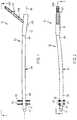
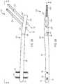
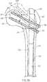
- FIG. 1is a front view of one embodiment of an intramedullary rod with pivotable fastener of the present invention.
- FIG. 2is a side view of the intramedullary rod with pivotable fastener of FIG. 1 taken along the line 2 - 2 of FIG. 1 .
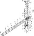
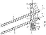
- FIG. 4is an enlarged cross sectional view of the intramedullary rod with pivotable fastener of FIG. 1 taken along the line 4 - 4 of FIG. 3 .
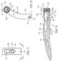
- FIG. 8is a side view of the nail of FIG. 7 taken along the line 8 - 8 of FIG. 7 .
- FIG. 9is a cross-sectional view of the nail of FIG. 7 taken along the line 9 - 9 of FIG. 7 .
- FIG. 10is a cross-sectional view of the proximal portion of the nail of FIG. 7 taken along the line 10 - 10 of FIG. 8 .
- FIG. 11is a side view of the head of the nail of FIG. 7 taken along the line 11 - 11 of FIG. 10 .
- FIG. 12is an top end view of the nail of FIG. 7 taken along the line 12 - 12 of FIG. 11 .
- FIG. 13is a cross-sectional view of the proximal portion of the nail of FIG. 7 taken along the line 13 - 13 of FIG. 12 .
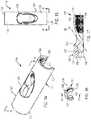
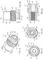
- FIG. 14is a perspective view of the insert of the intramedullary rod with pivotable fastener of FIG. 1 .
- FIG. 18is a perspective view of the end nut of the intramedullary rod with pivotable fastener of FIG. 1 .
- FIG. 19is a side view of the end nut of FIG. 18 taken along the line 19 - 19 of FIG. 18 .
- FIG. 21is top end view of the end nut of FIG. 18 taken along the line 21 - 21 of FIG. 19 .
- FIG. 23is a perspective view of the spindle of the intramedullary rod with pivotable fastener of FIG. 1 .
- FIG. 24is a side view of the spindle of FIG. 23 taken along the line 24 - 24 of FIG. 23 .
- FIG. 26is bottom end view of the spindle of FIG. 23 taken along the line 26 - 26 of FIG. 24 .
- FIG. 27is a cross-sectional view of the spindle of FIG. 23 taken along the line 27 - 27 of FIG. 25 .
- FIG. 28is a perspective view of the set screw of the intramedullary rod with fastener of FIG. 1 .
- FIG. 30is an end view of the set screw of FIG. 28 taken along the line 30 - 30 of FIG. 29 .
- FIG. 31is a cross-sectional view of the set screw of FIG. 28 taken along the line 31 - 31 of FIG. 30 .
- FIG. 32is a perspective view of the fastener of the intramedullary rod with fastener of FIG. 1 .
- FIG. 33is a side view of the fastener of FIG. 32 taken along the line 33 - 33 of FIG. 32 .
- FIG. 34is an end view of the fastener of FIG. 32 taken along the line 34 - 34 of FIG. 33 .
- FIG. 35is a cross-sectional view of the fastener of FIG. 32 taken along the line 35 - 35 of FIG. 34 .
- FIG. 36is a front view of the proximal portion of the intramedullary rod with pivotable fastener of FIG. 1 showing the fastener in the first position of FIG. 1 relative to the intramedullary rod and the fastener in a second position relative pivoted counterclockwise to the intramedullary rod.
- FIG. 37is a cross-sectional view of the proximal portion of the intramedullary rod and pivotable fastener of FIG. 1 showing the fastener in a third position relative to the intramedullary rod.
- FIG. 39is a side view of the intramedullary rod with pivotable fasteners of FIG. 38 taken along the line 39 - 39 of FIG. 38 .
- FIG. 40is a cross-sectional view of the intramedullary rod with pivotable fasteners of FIG. 38 taken along the line 40 - 40 of FIG. 39 .
- FIG. 41is a perspective view of the insert of the intramedullary rod with pivotable fasteners of FIG. 38 .
- FIG. 42is a top view of the insert of FIG. 41 taken along the line 42 - 42 of FIG. 41 .
- FIG. 43is an end view of the insert of FIG. 41 taken along the line 43 - 43 of FIG. 42 .
- FIG. 44is a cross-sectional view of the insert of FIG. 41 taken along the line 44 - 44 of FIG. 43 .
- FIG. 45is a perspective view of the spindle of the intramedullary rod with pivotable fasteners of FIG. 38 .
- FIG. 46is a side view of the spindle of FIG. 45 taken along the line 46 - 46 of FIG. 45 .
- FIG. 47is an end view of the spindle of FIG. 45 taken along the line 47 - 47 of FIG. 46 .
- FIG. 48is a cross-sectional view of the spindle of FIG. 45 taken along the line 48 - 48 of FIG. 47 .
- FIG. 49is a side view of the set screw of the intramedullary rod with pivotable fasteners of FIG. 38 .
- FIG. 50is an end view of the set screw of FIG. 49 taken along the line 50 - 50 of FIG. 49 .
- FIG. 51is a cross-sectional view of the set screw of FIG. 49 taken along the line 51 - 51 of FIG. 50 .
- FIG. 53is a front view of a distal portion of a further embodiment of an intramedullary rod with pivotable fasteners of the present invention.
- FIG. 54is a front view of a distal portion of a yet another embodiment of an intramedullary rod with pivotable fasteners of the present invention.
- FIG. 55is a side view of a distal portion of a yet a further embodiment of an intramedullary rod with pivotable fasteners of the present invention.
- FIG. 56is an end view of the intramedullary rod with pivotable fastener of FIG. 55 taken along the line 56 - 56 of FIG. 55 .
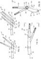
- FIG. 57is a schematic front view of the intramedullary rod with pivotable fasteners of FIG. 38 disposed in a femur to repair a femoral neck fracture.
- FIG. 58is a schematic front view of the intramedullary rod with pivotable fasteners of FIG. 38 disposed in a femur to repair an intertrochanteric fracture.
- FIG. 59is a schematic front view of the intramedullary rod with pivotable fasteners of FIG. 38 disposed in a femur to repair a subtrochanteric fracture.
- an apparatus or devicefor treating fractures, nonunions or malunions of the femur or other bones of a mammalian body and includes an intramedullary rod or nail and at least one fastener carried by the rod. At least one opening is provided in the head of the apparatus for slidably receiving the one or more fasteners and permitting the fastener or fasteners to pivot relative to the head of the apparatus.
- the apparatus 61 of the inventioncomprises an intramedullary rod 62 and a proximal fastener 63 pivotably carried by the proximal portion of the rod (see FIGS. 1-3 ).
- the proximal fastener 63can be of any suitable type, including a fixation screw, a screw, a peg, a helical blade or any other fixation device, and for simplicity is referred to herein as a fixation screw.
- the femoral nail or rod 62includes an elongate body 64 that extends along a longitudinal axis 66 and can have a proximal portion or head 67 , a central portion or neck 68 and a distal portion or shaft 69 that terminates at a distal tip 71 .
- the elongate body 64may curve in at least one portion of the shaft or stem 69 to align the rod 62 along the length of the marrow canal of the femur when the rod is inserted in the femur.
- the elongate body 64can be made from any suitable material such as stainless steel, titanium or another alloy and can have a length, dependent in part on the length in which the rod 62 is to be utilized, ranging from 180 to 500 centimeters.
- the head 67 of the nail 62can have a length ranging from four to 15 centimeters and preferably ranging from eight to 12 centimeters and a diameter ranging from eight to 20 millimeters.
- a longitudinally-extending passageway or bore 76can be provided and extends from a proximal opening 77 in the head 67 to an opening 78 in the tip of the stem for permitting the rod to slide along a guide wire during insertion of the rod into the femur.
- the curve of the longitudinal axis 66and thus the curve of the stem 69 of the rod 62 , can be through a single plane or through multiple planes. In the illustrated embodiment of nail 62 , as shown in FIGS. 8, 10, 12 and 13 , the curve of body 64 extends through multiple planes.
- first and second bores 81which can extend perpendicular to the longitudinal axis 66 , are provided in the distal end portion of the stem 69 adjacent the tapered tip 71 of the stem.
- the boresare sized to receive respective distal fasteners, such as fixation screws, screws, pegs, helical blades or any other suitable fixation devices, and in one embodiment such distal fasteners are in the form of fixation screws or screws 82 that can be fixed at an orthogonal angle relative to stem 69 .
- fixation screwsscrews, pegs, helical blades or any other suitable fixation devices
- the distal-most bore 81is elongated in its transverse direction, that is parallel to the longitudinal axis 66 of the stem 69 , to permit the stem to be moved longitudinally relative to the respective distal fastener or fixation screw 82 before tightening of the fastener or screw to the underlying portion of the femur.
- At least one transverse apertures or opening 91is provided through the head 67 of the rod 62 and in one embodiment is angled toward the proximal end of the rod relative to longitudinal axis 66 for receiving the proximal fixation screw or fixation screw 63 . More specifically, the one or more transverse apertures or holes 91 each pivotably receive a fixation screw 63 and allow for changing the angle made between the screw 63 and the nail 62 . Each such aperture or first hole can extend through the head 67 in an angled direction relative to longitudinal axis 66 such that when the rod is in position within the marrow canal of the femur, axis 92 of the opening is directed toward the head of the femur (see FIG. 13 ). As can be seen from FIGS.
- the transverse aperture or aperture 92 in the head 67can communicate with a first or lateral transverse opening 93 , through which the respective fixation screw is inserted, and an opposite second or medial transverse opening 94 , from which the distal portion of the screw extends.
- the medial transverse opening 94as shown in FIGS. 5, 8, 11 and 13 , can be elongate or oblong in a transverse direction, that is parallel to longitudinal axis 66 of head 67 and body 64 , so as to accommodate pivoting of the distal portion of the proximal fixation screw 63 .
- the head 67 of rod 62may include an actuation or adjustment mechanism or assembly 101 for selectively pivoting the proximal fixation screw 63 within the transverse aperture 91 (see FIGS. 4-31 ).
- the proximal portion of the central passageway 76 of the nail 62can be hollowed to form a longitudinally-extending proximal recess 102 in the head that communicates with a proximal opening 103 in the head. As illustrated in FIGS.
- the recess 102can have a proximal portion 102 a , adjacent the proximal opening 103 , and a segmented circular portion 102 b that extends in cross section through any suitable angle preferably ranging from 180 to 240 degrees and illustrated in FIG. 12 as approximately 240 degrees, along the inside of the head 67 adjacent the medial transverse opening 94 .
- Internal threads 104can be provided in proximal portion 102 a .
- the segmented circular portion or segmented portion 102 b of recess 102may be formed from an inner arcuate surface 105 .
- the other side of the recess 102can be formed with a first shelf 107 , a second shelf 108 and a third shelf 109 that can each extend further radially inwardly than the inner arcuate surface 105 of the segmented portion 102 b and can have increasingly smaller radii relative to longitudinal axis 66 (see FIGS. 11-13 ).
- the proximal portion of the first shelf 107can be optionally provided with internal threads 111 , as shown in FIGS. 4, 9 and 10 .
- a shoulder 112can extend radially inwardly from first shelf 107 to second shelf 108 (see FIG. 13 ).
- the third shelf 109may abut the lateral transverse opening 93 , as shown in FIG. 11 .
- Transversely aligned slots 110may be provided on the proximal end of head 67 at proximal opening 103 for registering the nail 62 with an insertion jig, targeting device or other suitable device when placing or otherwise manipulating the nail within the targeted bone.
- the actuation mechanism 101 for pivoting the proximal fixation screw 63can be of any suitable type, in one embodiment the mechanism 101 includes an insert or sleeve 116 , a spindle 117 , an end or safety nut 118 and an alignment or set screw 119 , as shown in the exploded views of FIGS. 5-6 and in the assembled view of FIG. 4 .
- Each of these componentscan be made from any suitable material such as stainless steel.
- Elongate insert or sleeve 116may be formed from a tubular-like member 121 that can have a proximal portion 122 and a distal portion 123 and a longitudinally-extending opening 124 extending through one side.
- Sleeve 116can have the shape of a cylinder with an elongate cutout 126 provided along one side thereof, opposite opening 124 , that communicates with the longitudinal bore 127 extending therethrough from proximal or top end 128 and distal or bottom end 129 .
- the planar top and bottom endscan extend parallel to each other.
- sleeve 116has a segmented circular or C shape when viewed from an end along its longitudinal axis, as shown in FIG.
- Such transverse, cross-sectional configuration of sleeve 116preferably approximates the cross-sectional configuration of the segmented circular portion 102 b of the recess 102 in head 67 and can extend through an arc ranging from 100 to 360 degrees, preferably ranging from 180 to 240 degrees and illustrated in FIG. 16 as approximately 240 degrees.
- the elongate transverse opening 124can be formed in the center of the insert. Such opening 124 may be oblong or elongate in shape and smaller than the medial transverse opening 94 provided in head 67 of the nail 62 .
- the insert 116may be provided with internal thread 131 extending through the bore 127 at the proximal portion 122 of the insert, such threads being adjacent the top or proximal end of the insert as shown in FIGS. 14 and 17 .
- the insertcan have a length ranging from 30 to 110 millimeters and can have an external radius sized to fit within head 67 of the nail 62 .
- the distal portion of internal bore 127that is the portion of the bore distal transverse opening 124 , has a smaller internal diameter than the internal diameter of the proximal portion of the bore.
- Spindle 117can be formed from a cylindrical body 136 provided with a distal portion 137 of constant radius and can have a smooth outer cylindrical surface 138 , a central portion 139 adjacent the distal portion and having external threads 141 extending radially outwardly relative to the distal portion and a proximal or neck portion 142 adjacent the central portion (see FIGS. 18-22 ).
- the neck portioncan include a proximal flange 143 and an annular recess 144 disposed between the flange and the central portion 139 of the spindle 117 .
- the cylindrical bodycan further include a proximal or top end 147 and a distal or bottom end 148 , as shown in FIG. 22 .
- the planar ends 148 and 148may extend parallel to each other.
- a central passageway or bore 151can extend through the spindle.
- the distal portion of the central passagewaymay be provided with internal thread 152 and the proximal portion of the central passageway may be provided with any suitable cross-sectional configuration for serving as a drive socket 153 .
- the spindlecan have a length ranging from five to 50 millimeters and preferably approximately 15 millimeters.
- End nut 118can be formed from a cylindrical body 161 provided with a distal portion 162 of constant radius and a smooth outer surface 163 and a proximal portion 164 adjacent the distal portion and having external threads 166 extending radially outwardly relative to the distal portion (see FIGS. 23-27 ).
- the cylindrical bodycan further include a proximal or top end 167 and a distal or bottom end 168 , as shown in FIG. 27 .
- Planar ends 167 and 168can extend parallel to each other.
- a central passageway or bore 171can extend longitudinally through the end nut between ends 167 and 168 and at least the proximal portion of the bore 171 can be provided with any suitable cross-sectional configuration for serving as a drive socket.
- the distal end portion of the end nutmay be provided with a recess or socket 172 , that can be in communication with bore 171 and be side opening onto the outer cylindrical surface 163 of the distal portion 162 .
- the socket 172can be sized and configured for cooperatively receiving the neck portion 142 of the spindle 117 and may include a partial annular flange 173 , shown most clearly in FIG. 24 , extending radially inwardly for partially seating in the annular recess 144 of the spindle and a partial annular recess 174 extending radially outwardly relative to the flange for receiving part of the proximal, annular flange 143 of the spindle.
- the end nutcan have a length ranging from five to 50 millimeters and preferably approximately 15 millimeters.
- Set screw 119can be formed from a cylindrical body 181 provided with a distal portion 182 of constant radius and a smooth outer surface 183 and a proximal portion 184 adjacent the distal portion and having external threads 186 extending radially outwardly relative to the distal portion (see FIGS. 28-31 ).
- the cylindrical body 181can further include a proximal or top end 187 and a distal or bottom end 188 , as shown in FIG. 29 .
- a drive socket 191 of any suitable cross-sectional configurationmay extend longitudinally through at least a portion of the cylindrical body and open at the top end 187 of the body.
- the bottom end 188 of the bodycan be blunted.
- the set screwcan have a length ranging from five to 60 millimeters and preferably approximately 20 millimeters.
- Proximal fastener 63 for use in the head 67 of the intramedullary rod 62can be of any suitable type and in one embodiment is made from an elongate cylindrical body 201 or spiral blade (not shown) having a length ranging from 40 to 200 millimeters and a diameter ranging from two to 20 millimeters (see FIGS. 32-35 ).
- the fasteneris a fixation screw formed from a body having a threaded portion and a smooth portion.
- the elongate body 201can be formed from any suitable material such as stainless steel and include a proximal portion 202 having any outer cylindrical or irregular-shaped surface 203 .
- the proximal portion 202may be provided with a plurality and as shown four longitudinally-extending slots 204 extending through the surface 203 in circumferentially-spaced apart positions.
- Distal portion 206 of the body 201may be provided with external threads 207 that extend to a sharpened distal end or tip 208 of the body.
- the distal portion 206 of the body 207may be irregularly shaped or flat (not shown).
- the bodycan further have a proximal end 211 and be provided with a central bore 212 that extends longitudinally through the body from the proximal end 211 to the distal end 208 (see FIG. 35 ).
- the proximal end of the central bore 212may be provided with internal threads 213 and be formed with a drive socket 214 of any suitable type for facilitating connection of the proximal fixation screw to a drive tool of any suitable type.
- insert or sleeve 116is slidably inserted through the proximal opening 103 of the head and slidably seated in the segmented circular portion 102 b of the recess 102 in the head.
- the transverse opening 124 in the insert 116is in general registration with the medial transverse opening 94 in the head 67 .
- the proximal or neck portion 142 of spindle 117is seated in the socket 172 formed in the distal portion 162 of end nut 118 so that the end nut and spindle are coaxial along the central longitudinal axes of the end nut and spindle.
- the combined spindle 117 and end nut 118 assemblyare loaded into the head 67 by introducing the distal portion 137 of the spindle into the proximal opening 103 in the head.
- a suitable drive tool(not shown) can be used to engage the drive socket in the central bore 171 at the proximal portion 164 of the end nut to rotate the end nut within the internal threads 104 adjacent the proximal opening 103 in the head so as to move the end nut 118 , and the spindle 117 captured thereby, longitudinally into the recess 102 of the head until the spindle seats is the distal portion of the first shelf 107 against shoulder 112 extending between the first shelf 107 and the second shelf 108 .
- the external threads 141 of the spindleengage the internal threads 131 on the proximal portion 122 of insert 116 .
- the spindlecan be moved longitudinally into threaded engagement with the insert by engagement of the drive socket 153 in the proximal or neck portion 142 of spindle 117 with a suitable drive tool and clockwise rotation of the spindle within the recess 102 of the head 67 .
- the set screw 119can thereafter be introduced through central bore 171 of the end nut 118 and into central bore 151 of the spindle 117 until the external threads 186 provided on the proximal end portion 184 of the set screw engage the internal threads 152 provided within the distal portion 137 of the spindle.
- a suitable drive toolmay be used to engage the drive socket 191 in the proximal portion 184 of the set screw 119 to move the set screw distally relative to the spindle 117 by the rotational engagement of the external threads 186 on the set screw with the internal threads 152 of the spindle.
- the distal portion 182 of the set screwcan thus be moved distally of the spindle 117 into the transverse aperture 91 in head 67 of the nail 62 .
- the fixation screwcan be pivoted about a transverse axis of the head through an angle of up to 70 degrees and preferably approximately 30 degrees relative to the nail 62 .
- the fixation screw 63is pivotable between a first position 216 , extending at an angle ⁇ of approximately 115 degrees relative to the stem 69 of the nail and shown in FIG. 36 , and a second position 217 , extending at an angle ⁇ of approximately 145 degrees relative to the stem of the nail and shown in FIG. 37 .
- the fixation screwis shown in an intermediate position 218 , extending at an angle ⁇ of approximately 130 degrees relative to the stem of the nail, in FIG. 36 .
- the physicianrotates the spindle 117 within the head 67 , for example by engaging the drive socket 153 in the neck portion 142 of the spindle with a suitable drive tool, so that the external threads 141 on the central portion 139 of the spindle that engage the internal threads 131 within the insert 116 cause the insert to move proximally within the head from a first or distal position in the segmented circular portion (not shown) to a second or proximal position in the segmented circular portion, illustrated in FIG. 37 .
- the distal end of the transverse opening 124 in the insert 116engages the fixation screw during proximal movement of the insert within the head 67 to cause the fixation screw to pivot within the medial transverse opening 93 of the transverse aperture 91 of the head.
- the spindle 117can rotate freely relative to the head and the end cap 118 .
- the set screw 119can be rotated distally with the spindle 117 so that the blunted end 188 of the set screw seats within one of the longitudinal slots 294 formed in the proximal portion 202 of the fixation screw 63 so as to rotatably lock the fixation screw relative to the head 67 of the intramedullary rod 62 and thus inhibit undesirable further advancement or withdrawal of the screw 63 relative to the rod 62 .
- actuation mechanism 101 of intramedullary rod 62has been shown and described with a longitudinally movable insert or sleeve 116 disposed within the nail, it is appreciated that an insert or sleeve slidably disposed on the outside of the nail 62 can be provided for pivoting the fixation screw 62 relative to the nail.
- FIGS. 38-52Another apparatus 231 is illustrated in FIGS. 38-52 and can includes an intramedullary rod 232 substantially similar to rod 62 . Like reference numerals have been utilized to describe like components of rods 62 and 232 .
- the intramedullary rod 232has any suitable first and second proximal fasteners, shown as first and second proximal fixation screws 233 and 234 that can each be substantially identical to proximal fixation screw 63 , pivotably received within respective first and second transverse apertures 236 and 237 that can each be substantially identical to transverse aperture 91 and extend along respective axes 92 .
- the first and second fasteners 233 and 234extend parallel to each other, may or may not be of the same length and may or may not be of the same type of fastener.
- the first fastener 233may be a screw and the second fastener 234 may be a peg or blade.
- the apertures 236 and 237are provided in a head 239 , substantially similar to head 67 , of the rod 232 .
- Actuation mechanism 241can be provided with the head 239 of the rod 232 .
- Actuation mechanism 241shown in an assembled position in FIG. 40 , can include an insert or sleeve 242 substantially similar to the insert 116 of mechanism 101 but having first and second transverse apertures 246 and 247 similar to transverse aperture 91 of the sleeve 116 and extending at an angle to the longitudinal axis of the nail for respectively receiving and pivoting the first and second fixation screws 233 and 234 (see FIGS. 41-44 ).
- the axes 92 of the first and second transverse apertures 246 and 247can be parallel to each other but may also not be parallel to each other.
- the insert 242can have a length ranging from 20 to 120 millimeters and an external radius sized to fit within head 239 of the nail 232 .
- a spindle 256can be provided that is substantially similar to the spindle 117 but formed without the distal portion 137 of spindle 117 (see FIGS. 45-48 ). Instead, spindle 256 of the dual fixation screw rod 232 of FIGS. 38-52 has a proximal or neck portion 142 and a distal portion 257 substantially similar to central portion 139 of the spindle 117 .
- the spindle 256can have a length ranging from five to 30 millimeters.
- An end cap or nut 266 substantially similar to end nut 118 but shorter in lengthcan be further provided (see FIGS. 49-51 ).
- the end nutcan have a length ranging from three to 30 millimeters.
- the proximal portion 142 of spindle 256is shown as being captured or seated in socket 172 in the distal portion 162 of end nut 266 in FIG. 52 so that the spindle and end cap are coaxially aligned in their operational positions relative to each other.
- actuation assembly 241can be loaded into head 239 of dual fixation screw rod 232 , and operated therein with respect to first and second proximal fixation screws 233 and 234 , in substantially the same manner as discussed above with respect to apparatus 61 .
- Sleeve 242is shown in FIG. 40 in its distal position.
- the inclusion in apparatus 241 of the second fixation screw 234minimizes the need for a set screw, such as set screw 119 , and preferably eliminates the need for such a set screw.
- the second proximal fixation screwis included in the means or mechanism of the rod 232 for preventing rotation of the head of the femur relative to the first proximal fixation screw 233 during use of rod 232 .
- an intramedullary rod of the present inventionfor inhibiting rotation of the head of the femur relative to the first fixation screw.
- the optional second aperture 237 and second proximal fixation screw 234allow sliding compression so as to prevent rotation and to adapt the apparatus or device to a variety of applications.
- FIG. 53A further embodiment of the intramedullary rod with pivotable fasteners of the present invention is illustrated in FIG. 53 wherein an apparatus 271 substantially similar to apparatus 61 and 231 is provided. Like reference numerals have been used to describe like components of apparatus 61 , 231 and 271 .
- Intramedullary rod or nail 272 of the apparatus 271is substantially similar to rods 62 and 232 and has any suitable first and second proximal fasteners, shown as first and second proximal fixation screws 233 and 234 .
- the first screw 233is pivotably received within first transverse aperture 236 extending along axis 92 .
- the second screw 234is pivotably received within a second transverse aperture 273 extending along an axis 274 .
- the aperture 273can be substantially identical to transverse aperture 236 except that axis 274 of the second transverse aperture 273 is not parallel to the axis 92 of the first transverse aperture 236 .
- the first and second fasteners 233 and 234extend nonparallel to each other, may or may not be of the same length and may or may not be of the same type of fastener.
- the apertures 236 and 273are provided in a head 276 of the rod 272 that is substantially similar to head 239 of rod 232 .
- An actuation mechanism or assemblysubstantially similar to actuation mechanism 241 but modified to provide for the nonparallel disposition of apertures 236 and 273 is provided.
- FIG. 54Another embodiment in the form or apparatus 281 is illustrated in FIG. 54 and can include an intramedullary rod 282 substantially similar to rods 62 and 232 . Like reference numerals have been utilized to describe like components of rods 62 , 232 and 282 .
- the intramedullary rod 282has any suitable first, second and third proximal fasteners, shown as first, second and third proximal fixation screws 233 , 234 and 283 , pivotably received within respective first, second and third transverse apertures 236 , 237 and 286 .
- the third proximal fixation screw 283can be identical to one or both of first and second proximal fixation screws 233 and 234 , and the third transverse aperture 286 can be identical to one or both of first and second transverse apertures 236 and 237 .
- the first, second and third fasteners 233 , 234 and 283may or may not extend parallel to each other, may or may not be of the same length and may or may not be of the same type of fastener. In the illustrated embodiment, the fasteners 233 , 234 and 283 extend parallel to each other.
- the apertures 236 , 237 and 286are provided in a head 287 of the rod 282 that is substantially similar to head 239 of rod 232 .
- An actuation mechanism or assemblysubstantially similar to actuation mechanism 241 but modified to provide for the third transverse aperture 286 can be provided.
- FIGS. 55-56Yet a further embodiment of the intramedullary rod with pivotable fasteners of the present invention is illustrated in FIGS. 55-56 wherein an apparatus 296 substantially similar to apparatus 61 and 231 is provided. Like reference numerals have been used to describe like components of apparatus 61 , 231 and 296 .
- Intramedullary rod or nail 297 of the apparatus 296is substantially similar to rods 62 and 232 and has any suitable first and second proximal fasteners, shown as first and second proximal fixation screws 233 and 234 .
- the first screw 233is pivotably received within first transverse aperture 236 extending along axis 92 .
- the second screw 234is pivotably received within a second transverse aperture 298 extending along an axis 299 .
- the second transverse aperture 298can be substantially identical to the first transverse aperture 236 except that axis 299 of the second transverse aperture 298 is not parallel to the axis 92 of the first transverse aperture 236 . More specifically, axis 299 is circumferentially angled about the longitudinal axis 66 of rod 297 relative to axis 92 , as shown in FIG. 56 by angle ⁇ . Angle ⁇ can be any suitable number. Axes 92 and 299 can extend at the same angle relative to longitudinal axis 66 , such as axes 92 of rod 232 as shown in FIG. 38 , or can extend at different angles relative to longitudinal axis 66 , such as axes 92 and 274 of rod 272 as shown in FIG. 53 .
- the first and second fasteners 233 and 234may or may not be of the same length and may or may not be of the same type of fastener.
- the apertures 236 and 298are provided in a head 301 of the rod 297 that is substantially similar to head 239 of rod 232 .
- An actuation mechanism or assemblysubstantially similar to actuation mechanism 241 but modified to provide for the different circumferential alignment of apertures 236 and 298 is provided.
- the fastenerscan be of any suitable number. Where multiple fasteners are provided, the fasteners can extend parallel to each other or at various angles to each other relative to the longitudinal axis and about the longitudinal axis of the nail.
- Extrapolations of the illustrated apparatuscan be provided, for example where three nonparallel fasteners are provided, where multiple fasteners are circumferentially aligned relative to each other about the longitudinal axis of the rod but spaced the same distance from the proximal end of the rod or where two or more first fasteners are circumferentially aligned relative to such longitudinal axis and one or more second fasteners are circumferentially spaced apart about such longitudinal axis relative to the first fasteners.
- the apparatus of the inventionhas been illustrated as having a separate transverse aperture in the rod for each fastener, it is appreciated that multiple fasteners can pivotably extend through a single transverse aperture.
- a single transverse aperturereceives two fasteners
- one or both of the aperture in the rod and the aperture in the actuation mechanismhas a configuration that narrows between two end portions of such aperture such that the two fasteners extending through respective end portions of such aperture are separated from each other by the narrowed material of the rod and/or the actuation mechanism.
- FIGS. 57-59Several procedures for utilizing the intramedullary rod with pivotable fixation screws of the present invention are illustrated in FIGS. 57-59 , where apparatus 231 with dual fixation screw rod 232 is shown in use to repair peritrochanteric fractures of a femur 311 . More specifically, 232 rod is shown repairing a femoral neck fracture 316 , an intertrochanteric fracture 317 and a subtrochanteric fracture 318 , respectively, in FIGS. 57-59 . Previous to the procedure of the invention, the rod 233 was introduced through the greater trochanter 321 into the medullary canal 322 in the shaft 323 of the femur.
- Suitable holes 324were made in the side of the greater trochanter to allow insertion of the first and second fixation screws 233 and 234 into the lateral transverse openings 93 of the respective first and second transverse apertures 236 and 237 in the head 239 of the rod.
- the fixation screwswere thereafter screwed into the head 326 of the femur 311 . In each instance, however, further adjustment of the head of the femur may be required either because the fracture is malreduced, the entry point for the rod in the greater trochanter was too lateral or a combination of the foregoing.
- a suitable drive (not shown) elementis introduced through the entry point 327 in the femur into the proximal opening 103 in the head 239 of the nail 232 and through the end nut 266 so as to seat within the drive socket 153 in the neck portion 142 of the spindle 256 .
- the spindle 256is rotated by the drive element, for example in a clockwise direction, so that the external threads 141 on the spindle engaged with the internal threads 131 on the proximal portion 122 of the insert or sleeve 242 and cause the insert 242 to slide or move proximally within the head 239 and thus cause each of the first and second proximal fixation screws 233 and 234 to pivot upwardly toward the head 239 of the rod, that is in a clockwise direction in FIGS. 57-59 , until the fracture is reduced and the head 326 of the femur 311 is brought out of varus and thus properly positioned relative to the remainder of the femur, as shown in phantom lines in FIGS. 57-59 .
- the first and second proximal fixation screwsare identified as 233 ′ and 234 ′ in FIGS. 57-59 when in their second position in which they have been pivoted upwardly toward the head 239 of the rod 232 .
- the second fixation screw 234inhibits, if not prevents, rotation of the femoral head 326 relative to the first fixation screw 233 .
- the apparatus of the inventioncan include more than two proximal fasteners to fixate head 326 of the femur, or a portion of any other suitable bone, and be within the scope of the present invention.
- an apparatusfor treating fractures of the femur that marries the fixation attributes of an intramedullary nail with the benefits of a sliding compression screw.
- the apparatusprovides a single device for treating a variety of femoral fractures, which heretofore have required more than one device.
- the devicecan be used to treat a variety of femoral fractures and femoral osteotomies and permits hospitals and manufacturers to reduce the variety of inventories of orthopedic surgical devices and thereby reduce costs.
- the deviceallows physicians to move the fracture or osteotomy to a more favorable position after implantation, and for example allows sliding compression of a femoral neck or intertrochanteric fracture.
- the apparatuspermits the physician to vary the angle of the proximal fixation screws extending into the head of the femur, which can be done before insertion or after insertion of the femoral rod into the femoral intramedullary canal.
Landscapes
- Health & Medical Sciences (AREA)
- Orthopedic Medicine & Surgery (AREA)
- Surgery (AREA)
- Life Sciences & Earth Sciences (AREA)
- Heart & Thoracic Surgery (AREA)
- Nuclear Medicine, Radiotherapy & Molecular Imaging (AREA)
- Engineering & Computer Science (AREA)
- Biomedical Technology (AREA)
- Neurology (AREA)
- Medical Informatics (AREA)
- Molecular Biology (AREA)
- Animal Behavior & Ethology (AREA)
- General Health & Medical Sciences (AREA)
- Public Health (AREA)
- Veterinary Medicine (AREA)
- Surgical Instruments (AREA)
Abstract
Description
Claims (15)
Priority Applications (2)
| Application Number | Priority Date | Filing Date | Title |
|---|---|---|---|
| US15/864,360US10687871B2 (en) | 2007-06-22 | 2018-01-08 | Intramedullary rod for pivoting a fastener |
| US16/908,649US20200315673A1 (en) | 2007-06-22 | 2020-06-22 | Intramedullary rod with pivotable fastener and method for using same |
Applications Claiming Priority (4)
| Application Number | Priority Date | Filing Date | Title |
|---|---|---|---|
| US93688707P | 2007-06-22 | 2007-06-22 | |
| US12/143,798US8906023B2 (en) | 2007-06-22 | 2008-06-22 | Intramedullary rod for pivoting a fastener |
| US14/555,232US9861403B2 (en) | 2007-06-22 | 2014-11-26 | Method for pivoting a fastener |
| US15/864,360US10687871B2 (en) | 2007-06-22 | 2018-01-08 | Intramedullary rod for pivoting a fastener |
Related Parent Applications (1)
| Application Number | Title | Priority Date | Filing Date |
|---|---|---|---|
| US14/555,232DivisionUS9861403B2 (en) | 2007-06-22 | 2014-11-26 | Method for pivoting a fastener |
Related Child Applications (1)
| Application Number | Title | Priority Date | Filing Date |
|---|---|---|---|
| US16/908,649ContinuationUS20200315673A1 (en) | 2007-06-22 | 2020-06-22 | Intramedullary rod with pivotable fastener and method for using same |
Publications (2)
| Publication Number | Publication Date |
|---|---|
| US20180125546A1 US20180125546A1 (en) | 2018-05-10 |
| US10687871B2true US10687871B2 (en) | 2020-06-23 |
Family
ID=40186001
Family Applications (4)
| Application Number | Title | Priority Date | Filing Date |
|---|---|---|---|
| US12/143,798Active2030-11-22US8906023B2 (en) | 2007-06-22 | 2008-06-22 | Intramedullary rod for pivoting a fastener |
| US14/555,232ActiveUS9861403B2 (en) | 2007-06-22 | 2014-11-26 | Method for pivoting a fastener |
| US15/864,360Active2028-08-05US10687871B2 (en) | 2007-06-22 | 2018-01-08 | Intramedullary rod for pivoting a fastener |
| US16/908,649AbandonedUS20200315673A1 (en) | 2007-06-22 | 2020-06-22 | Intramedullary rod with pivotable fastener and method for using same |
Family Applications Before (2)
| Application Number | Title | Priority Date | Filing Date |
|---|---|---|---|
| US12/143,798Active2030-11-22US8906023B2 (en) | 2007-06-22 | 2008-06-22 | Intramedullary rod for pivoting a fastener |
| US14/555,232ActiveUS9861403B2 (en) | 2007-06-22 | 2014-11-26 | Method for pivoting a fastener |
Family Applications After (1)
| Application Number | Title | Priority Date | Filing Date |
|---|---|---|---|
| US16/908,649AbandonedUS20200315673A1 (en) | 2007-06-22 | 2020-06-22 | Intramedullary rod with pivotable fastener and method for using same |
Country Status (10)
| Country | Link |
|---|---|
| US (4) | US8906023B2 (en) |
| EP (2) | EP2166970B1 (en) |
| JP (1) | JP5566287B2 (en) |
| KR (1) | KR101503665B1 (en) |
| CN (1) | CN101754723B (en) |
| AU (1) | AU2008268507C1 (en) |
| BR (1) | BRPI0813156A2 (en) |
| CA (1) | CA2690786C (en) |
| ES (1) | ES2595308T3 (en) |
| WO (1) | WO2009002890A1 (en) |
Families Citing this family (65)
| Publication number | Priority date | Publication date | Assignee | Title |
|---|---|---|---|---|
| US8303590B2 (en)* | 2007-01-26 | 2012-11-06 | Ebi, Llc | Lockable intramedullary fixation device |
| US9308031B2 (en) | 2007-01-26 | 2016-04-12 | Biomet Manufacturing, Llc | Lockable intramedullary fixation device |
| US9320551B2 (en) | 2007-01-26 | 2016-04-26 | Biomet Manufacturing, Llc | Lockable intramedullary fixation device |
| US8157802B2 (en)* | 2007-01-26 | 2012-04-17 | Ebi, Llc | Intramedullary implant with locking and compression devices |
| KR101503665B1 (en) | 2007-06-22 | 2015-03-18 | 이픽스 오소페딕스, 인코포레이티드 | Intramedullary rod for pivoting a fastener |
| US8394103B2 (en) | 2007-10-16 | 2013-03-12 | Biomet Manufacturing Corp. | Method and apparatus for orthopedic fixation |
| US8328806B2 (en)* | 2008-06-24 | 2012-12-11 | Extremity Medical, Llc | Fixation system, an intramedullary fixation assembly and method of use |
| US8313487B2 (en)* | 2008-06-24 | 2012-11-20 | Extremity Medical Llc | Fixation system, an intramedullary fixation assembly and method of use |
| US9289220B2 (en)* | 2008-06-24 | 2016-03-22 | Extremity Medical Llc | Intramedullary fixation assembly and method of use |
| US9044282B2 (en) | 2008-06-24 | 2015-06-02 | Extremity Medical Llc | Intraosseous intramedullary fixation assembly and method of use |
| US20110230884A1 (en)* | 2008-06-24 | 2011-09-22 | Adam Mantzaris | Hybrid intramedullary fixation assembly and method of use |
| US9017329B2 (en)* | 2008-06-24 | 2015-04-28 | Extremity Medical, Llc | Intramedullary fixation assembly and method of use |
| US8343199B2 (en)* | 2008-06-24 | 2013-01-01 | Extremity Medical, Llc | Intramedullary fixation screw, a fixation system, and method of fixation of the subtalar joint |
| US8303589B2 (en) | 2008-06-24 | 2012-11-06 | Extremity Medical Llc | Fixation system, an intramedullary fixation assembly and method of use |
| US8790343B2 (en)* | 2008-10-11 | 2014-07-29 | Epix Orthopaedics, Inc. | Intramedullary rod with pivotable and fixed fasteners and method for using same |
| ES2524076T3 (en)* | 2008-10-15 | 2014-12-04 | Zimmer Gmbh | Intramedullary nail |
| CA2749684C (en) | 2009-01-16 | 2016-04-26 | Carbofix Orthopedics Ltd. | Composite material bone implant |
| US9295504B2 (en)* | 2009-03-31 | 2016-03-29 | Biomet C.V. | Intramedullary nail with locking key |
| US8915917B2 (en)* | 2009-08-13 | 2014-12-23 | Cork Institute Of Technology | Intramedullary nails for long bone fracture setting |
| US10154867B2 (en) | 2010-06-07 | 2018-12-18 | Carbofix In Orthopedics Llc | Multi-layer composite material bone screw |
| CN105877829B (en) | 2010-06-07 | 2018-06-22 | 卡波菲克斯整形有限公司 | Composite material bone implant |
| KR101789498B1 (en) | 2010-07-09 | 2017-10-25 | 신세스 게엠바하 | Intramedullary nail |
| FR2965471B1 (en)* | 2010-09-30 | 2013-07-26 | Christian Cuny | INTRAMEDULAR FASTENING ASSEMBLY |
| CA2825444C (en) | 2011-02-08 | 2016-01-12 | Stryker Trauma Gmbh | Implant system for bone fixation |
| BR112013020956B1 (en)* | 2011-02-14 | 2020-12-08 | Synthes Gmbh | bone fixation set |
| TWI434667B (en)* | 2011-03-30 | 2014-04-21 | Metal Ind Res & Dev Ct | Medical instrument with three dimensional fixation shape memory intramedullary nail |
| US9220544B2 (en)* | 2011-12-15 | 2015-12-29 | Epix Orthopaedics, Inc. | Implantable device with locking adjustment mechanism and method for using same |
| US9526549B2 (en) | 2012-01-16 | 2016-12-27 | Carbofix Orthopedics Ltd. | Bone screw with insert |
| JP6247644B2 (en)* | 2012-02-08 | 2017-12-13 | エピックス オーソペディックス インコーポレイテッド | Implant insertion device having a continuously adjustable targeting assembly |
| CN107184248B (en)* | 2012-02-08 | 2020-02-21 | Epix整形外科股份有限公司 | Implant Insertion Device |
| US9017055B2 (en) | 2012-07-12 | 2015-04-28 | Biomet Manufacturing, Llc | Device for coating intramedullary rods with cement |
| EP2916742B1 (en) | 2012-11-12 | 2018-08-29 | Ziran, Navid | Dynamic axial nail for intramedullary treatment of long bone fractures |
| US10123828B2 (en)* | 2013-03-15 | 2018-11-13 | Epix Orthopaedics, Inc. | Implantable device with pivotable fastener and self-adjusting set screw |
| US9468478B2 (en) | 2013-07-24 | 2016-10-18 | Sreevathsa Boraiah | Interlocking intramedullary rod assembly for proximal femoral fractures, including unstable hip fractures |
| US9757169B2 (en)* | 2013-07-24 | 2017-09-12 | Sreevathsa Boraiah | Interlocking intramedullary rod assembly for proximal femoral fractures, including unstable hip fractures |
| ES2805053T3 (en) | 2013-12-09 | 2021-02-10 | Acumed Llc | Nail-based elastic hip fixation system |
| US9433451B2 (en) | 2013-12-09 | 2016-09-06 | Acumed Llc | Hip fixation system with a compliant fixation element |
| US9526542B2 (en)* | 2014-05-07 | 2016-12-27 | Acumed Llc | Hip fixation with load-controlled dynamization |
| US9463055B2 (en) | 2013-12-09 | 2016-10-11 | Acumed Llc | Plate-based compliant hip fixation system |
| US10080596B2 (en) | 2013-12-09 | 2018-09-25 | Acumed Llc | Hip fixation with load-controlled dynamization |
| JP6562595B2 (en)* | 2014-05-21 | 2019-08-21 | ディトマール・ヴォルター | Osteosynthesis system for multi-directional, angle-stable treatment of tubular fractures with intramedullary nails and bone screws |
| JP6562596B2 (en)* | 2014-05-21 | 2019-08-21 | ディトマール・ヴォルター | Osteosynthesis system for multi-directional, angle-stable treatment of tubular fractures with intramedullary nails and bone screws |
| US20220151664A1 (en)* | 2015-04-16 | 2022-05-19 | Texas Tech University System | Ankle (Tibio-Talar) Fusion Nail |
| US11253298B2 (en)* | 2015-05-22 | 2022-02-22 | Stryker European Operations Holdings Llc | Implant system for bone fixation |
| US10617458B2 (en) | 2015-12-23 | 2020-04-14 | Carbofix In Orthopedics Llc | Multi-layer composite material bone screw |
| UY37137A (en) | 2016-02-24 | 2017-09-29 | Merial Inc | ANTIPARASITARY COMPOUNDS OF ISOXAZOLINE, INJECTABLE FORMULATIONS OF PROLONGED ACTION THAT INCLUDE THEM, METHODS AND USES OF THE SAME |
| US10219846B2 (en)* | 2016-03-04 | 2019-03-05 | Nail Kinetics, LLC | Interlocking intramedullary rod assembly for treating proximal tibial fractures |
| WO2018042595A1 (en)* | 2016-09-01 | 2018-03-08 | 株式会社オーミック | Thighbone fixing tool |
| US10299847B2 (en)* | 2016-09-22 | 2019-05-28 | Globus Medical, Inc. | Systems and methods for intramedullary nail implantation |
| US10492803B2 (en) | 2016-09-22 | 2019-12-03 | Globus Medical, Inc. | Systems and methods for intramedullary nail implantation |
| US11083503B2 (en) | 2016-09-22 | 2021-08-10 | Globus Medical, Inc. | Systems and methods for intramedullary nail implantation |
| MX2019004076A (en)* | 2016-10-10 | 2019-06-10 | Ferrero Manzanal Francisco | Intramedullary nailing system of variable angle to treat femur fractures. |
| US10716682B2 (en) | 2017-07-19 | 2020-07-21 | Acumed Llc | Orthopedic alignment guide |
| US10952774B2 (en)* | 2017-08-07 | 2021-03-23 | The Solsidan Group, LLC | Orthopaedic fixation assembly, system, and method of use |
| EP3466357B1 (en)* | 2017-10-09 | 2022-01-05 | Globus Medical, Inc. | Systems intramedullary nail implantation |
| US11446072B2 (en) | 2017-10-10 | 2022-09-20 | DePuy Synthes Products, Inc. | Self-retaining nail to insertion handle interface |
| US10932828B2 (en) | 2018-01-25 | 2021-03-02 | Advanced Orthopaedic Solutions, Inc. | Bone nail |
| CN109394325B (en)* | 2018-10-26 | 2024-07-02 | 上海大博医疗科技有限公司 | Adjustable intramedullary nail and medical implantation fixing system |
| US10856916B2 (en)* | 2018-11-15 | 2020-12-08 | DePuy Synthes Products, Inc. | Flexible shaft guide tube |
| US11633219B2 (en) | 2019-06-26 | 2023-04-25 | Globus Medical, Inc. | Fenestrated pedicle nail |
| CN110811802B (en)* | 2019-09-11 | 2020-11-20 | 杭州辰昀企业管理有限公司 | Reduction support assembly for treating femoral fracture |
| US12207849B2 (en) | 2020-03-06 | 2025-01-28 | Stryker European Operations Limited | Set screw for femoral nail |
| WO2021176272A1 (en) | 2020-03-06 | 2021-09-10 | Stryker European Operations Limited | Set screw for femoral nail |
| CN116133605A (en) | 2020-05-29 | 2023-05-16 | 史赛克欧洲运营有限公司 | Funnel Hole for Intramedullary Nails |
| US12004785B2 (en) | 2022-04-21 | 2024-06-11 | DePuy Synthes Products, Inc. | Retrograde femoral intramedullary nail, and related systems and methods |
Citations (105)
| Publication number | Priority date | Publication date | Assignee | Title |
|---|---|---|---|---|
| US2181746A (en) | 1939-02-04 | 1939-11-28 | John R Siebrandt | Combination bone clamp and adjustable drill guide |
| US2441765A (en) | 1945-04-28 | 1948-05-18 | Surgical Specialties Corp | Surgical device |
| US3308812A (en) | 1964-05-27 | 1967-03-14 | Gidlund Ake Samuel | Device for osteosynthesis |
| US3783860A (en) | 1972-10-27 | 1974-01-08 | Sampson Corp | Intramedullary rod |
| US4519100A (en) | 1982-09-30 | 1985-05-28 | Orthopedic Equipment Co. Inc. | Distal locking intramedullary nail |
| US4622959A (en) | 1985-03-05 | 1986-11-18 | Marcus Randall E | Multi-use femoral intramedullary nail |
| US4653487A (en) | 1986-01-29 | 1987-03-31 | Maale Gerhard E | Intramedullary rod assembly for cement injection system |
| US4657001A (en) | 1984-07-25 | 1987-04-14 | Fixel Irving E | Antirotational hip screw |
| US4733654A (en) | 1986-05-29 | 1988-03-29 | Marino James F | Intramedullar nailing assembly |
| US4776330A (en) | 1986-06-23 | 1988-10-11 | Pfizer Hospital Products Group, Inc. | Modular femoral fixation system |
| US4827917A (en) | 1986-12-30 | 1989-05-09 | Richards Medical Company | Fermoral fracture device |
| US4846162A (en) | 1987-09-14 | 1989-07-11 | Moehring H David | Orthopedic nail and method of bone fracture fixation |
| US4875475A (en) | 1984-11-30 | 1989-10-24 | Synthes (U.S.A.) | Device for treating a bone |
| US4881535A (en) | 1988-09-06 | 1989-11-21 | Sohngen Gary W | Intramedullary rod targeting device |
| US5032125A (en) | 1990-02-06 | 1991-07-16 | Smith & Nephew Richards Inc. | Intramedullary hip screw |
| US5047034A (en) | 1990-05-29 | 1991-09-10 | Ace Orthopedic Manufacturing | Intramedullary rod screw guide |
| US5127913A (en) | 1991-04-22 | 1992-07-07 | Thomas Jr Charles B | Apparatus and method for implanting an intramedullary rod |
| US5167663A (en) | 1986-12-30 | 1992-12-01 | Smith & Nephew Richards Inc. | Femoral fracture device |
| US5176681A (en) | 1987-12-14 | 1993-01-05 | Howmedica International Inc. | Intramedullary intertrochanteric fracture fixation appliance and fitting device |
| US5190544A (en) | 1986-06-23 | 1993-03-02 | Pfizer Hospital Products Group, Inc. | Modular femoral fixation system |
| US5248313A (en) | 1991-04-17 | 1993-09-28 | Greene Bruce L | Fibular intramedullary rod |
| US5295991A (en) | 1991-05-24 | 1994-03-22 | Synthes (U.S.A.) | Surgical instrument for positioning osteosynthetic elements |
| US5429640A (en) | 1992-11-27 | 1995-07-04 | Clemson University | Intramedullary rod for fracture fixation of femoral shaft independent of ipsilateral femoral neck fracture fixation |
| US5454813A (en) | 1991-06-24 | 1995-10-03 | Howmedica International Inc. | Intramedullary intertrochanteric fracture fixation appliance |
| EP0696441A2 (en) | 1994-08-10 | 1996-02-14 | Howmedica GmbH | Means for the stabilization of long bones, especially for the osteotomy |
| US5514137A (en) | 1993-12-06 | 1996-05-07 | Coutts; Richard D. | Fixation of orthopedic devices |
| WO1997039693A1 (en) | 1996-04-25 | 1997-10-30 | Nuvana Medical Innovations, L.L.C. | Intermedullary rod apparatus and methods of repairing proximal humerus fractures |
| EP0845245A2 (en) | 1996-11-22 | 1998-06-03 | Howmedica GmbH | A locking marrow nail with adjustable openings for locking screws |
| US5935127A (en) | 1997-12-17 | 1999-08-10 | Biomet, Inc. | Apparatus and method for treatment of a fracture in a long bone |
| US6120504A (en) | 1998-12-10 | 2000-09-19 | Biomet Inc. | Intramedullary nail having dual distal bore formation |
| US6123708A (en) | 1999-02-03 | 2000-09-26 | Pioneer Laboratories, Inc. | Intramedullary bone fixation rod |
| US6126661A (en) | 1997-01-20 | 2000-10-03 | Orthofix S.R.L. | Intramedullary cavity nail and kit for the treatment of fractures of the hip |
| US6221074B1 (en) | 1999-06-10 | 2001-04-24 | Orthodyne, Inc. | Femoral intramedullary rod system |
| US6235031B1 (en) | 2000-02-04 | 2001-05-22 | Encore Medical Corporation | Intramedullary fracture fixation device |
| US6406477B1 (en) | 2000-07-27 | 2002-06-18 | Koi Inc. | Intramedullary nail |
| US6443954B1 (en) | 2001-04-24 | 2002-09-03 | Dale G. Bramlet | Femoral nail intramedullary system |
| US20020133156A1 (en) | 1999-06-10 | 2002-09-19 | Cole J. Dean | Femoral intramedullary rod system |
| US20020151898A1 (en) | 1999-10-21 | 2002-10-17 | Sohngen Gary W. | Modular intramedullary nail |
| US20020156473A1 (en) | 2001-04-24 | 2002-10-24 | Bramlet Dale G. | Intramedullary hip nail with bifurcated lock |
| US6488684B2 (en) | 2001-04-25 | 2002-12-03 | Dale G. Bramlet | Intramedullary nail |
| US20030036758A1 (en) | 1999-07-07 | 2003-02-20 | Robert Frigg | Angle-adjustable bone screw and device for osteosynthetic bone fixation |
| US6562042B2 (en) | 2000-02-02 | 2003-05-13 | Owen A. Nelson | Orthopedic implant used to repair intertrochanteric fractures and a method for inserting the same |
| US20030114855A1 (en) | 1997-03-19 | 2003-06-19 | Stryker Trauma-Selzach Ag | Modular intramedullary nail |
| WO2003053265A1 (en) | 2001-12-20 | 2003-07-03 | Merete Medical Gmbh | Modular bone nail |
| GB2387112A (en) | 2002-02-23 | 2003-10-08 | Odathurai Nallasam Paramasivan | Bone fracture compression assembly |
| EP1356777A2 (en) | 2002-04-15 | 2003-10-29 | HIT MEDICA S.r.L. | Screw Guide for an intramedullary nail |
| US6702816B2 (en) | 2001-05-25 | 2004-03-09 | Sulzer Orthopedics Ltd. | Femur marrow nail for insertion at the knee joint |
| US20040106922A1 (en) | 1998-11-11 | 2004-06-03 | Snyder Samuel J. | Apparatus and method for targeting and/or installing screws into intramedullary nails |
| US6783529B2 (en) | 1999-04-09 | 2004-08-31 | Depuy Orthopaedics, Inc. | Non-metal inserts for bone support assembly |
| WO2004096067A2 (en) | 2003-04-29 | 2004-11-11 | Grampian University Hospitals Nhs Trust | Bone fixture apparatus |
| US20050010226A1 (en) | 2003-05-30 | 2005-01-13 | Grady Mark P. | Bone plate |
| US6860691B2 (en) | 2001-06-18 | 2005-03-01 | John Duncan Unsworth | Self adjusting, high strength, screw system |
| US20050055023A1 (en) | 2002-07-23 | 2005-03-10 | Advanced Orthopaedic Solutions, Inc. | Intramedullary nail for long bone fractures |
| US20050085812A1 (en) | 2003-10-21 | 2005-04-21 | Sherman Michael C. | Apparatus and method for providing dynamizable translations to orthopedic implants |
| US20050149025A1 (en) | 2003-09-08 | 2005-07-07 | Joseph Ferrante | Orthopaedic plate and screw assembly |
| EP1557131A1 (en) | 2004-01-20 | 2005-07-27 | Depuy Orthopaedics, Inc. | Intramedullary nail for static or dynamic fixation |
| US20050182406A1 (en) | 2004-01-23 | 2005-08-18 | Orbay Jorge L. | System for stabilization of fractures of convex articular bone surfaces including subchondral support structure |
| US20050182405A1 (en) | 2004-01-23 | 2005-08-18 | Orbay Jorge L. | System for stabilization of fractures of convex articular bone surfaces including subchondral support structure |
| JP2005270503A (en) | 2004-03-26 | 2005-10-06 | Koki Shimizu | Osteosynthesis equipment |
| WO2005092219A1 (en) | 2004-03-26 | 2005-10-06 | Hirotaka Shimizu | Bone connecting tool |
| WO2005094707A2 (en) | 2004-03-26 | 2005-10-13 | Smith & Nephew, Inc. | Methods for treating fractures of the femur and femoral fracture devices |
| US20060015101A1 (en) | 2004-07-15 | 2006-01-19 | Wright Medical Technology, Inc. | Intramedullary fixation assembly and devices and methods for installing the same |
| US7008425B2 (en) | 1999-05-27 | 2006-03-07 | Jonathan Phillips | Pediatric intramedullary nail and method |
| US20060058887A1 (en) | 2004-09-15 | 2006-03-16 | Desmet Koen | Unitary acetabular cup prosthesis with extension for deficient acetabulum |
| EP1639953A1 (en) | 2004-09-27 | 2006-03-29 | Orthofix International B.V. | Intramedullary nail for the treatment of proximal femur fractures |
| US20060106398A1 (en) | 2004-11-18 | 2006-05-18 | Carl Lauryssen | Cervical bone preparation tool and implant guide systems |
| WO2006066440A2 (en) | 2004-12-23 | 2006-06-29 | Staeubli Hans Ulrich | Bone fixing device |
| WO2006091625A2 (en) | 2005-02-22 | 2006-08-31 | Smith & Nephew, Inc. | Instrument for targeting blocking screws |
| US20070049939A1 (en) | 2005-08-31 | 2007-03-01 | Wallace Matthew S | Intramedullary nail assembly with sleeve and screw for use therewith |
| US20070049940A1 (en) | 2005-08-31 | 2007-03-01 | Wallace Matthew S | Intramedullary nail assembly with fixed securement and associated method |
| US20070049938A1 (en) | 2005-08-31 | 2007-03-01 | Wallace Matthew S | Intramedullary nail assembly with locking component, locking component and nail for use therewith |
| US20070100343A1 (en) | 2003-05-17 | 2007-05-03 | Cole Dean J | Intramedullary nail assembly |
| US20070123876A1 (en) | 2005-10-31 | 2007-05-31 | Czartoski Timothy J | Multiple purpose nail, nail assembly and associated method |
| US20070123878A1 (en) | 2005-10-21 | 2007-05-31 | Shaver Joseph A | Orthopedic rod with locking aperture |
| JP2007143942A (en) | 2005-11-29 | 2007-06-14 | Tetsuo Nakano | Fracture adjusting joining device |
| US20070162016A1 (en) | 2005-10-25 | 2007-07-12 | Matityahu Amir M | Bone fastening assembly and bushing and screw for use therewith |
| US20070179835A1 (en) | 2006-02-02 | 2007-08-02 | Yahoo! Inc. | Syndicated ratings and reviews |
| US7267678B2 (en) | 2003-09-30 | 2007-09-11 | Robert J. Medoff | Intramedullary implant for fracture fixation |
| US20070233104A1 (en) | 2006-03-31 | 2007-10-04 | Metzinger Anthony J | Intramedullary nail implant assembly, kit and method |
| US20070233103A1 (en) | 2006-03-31 | 2007-10-04 | Metzinger Anthony J | Intramedullary nail, intramedullary nail assembly and method |
| US20070233101A1 (en) | 2006-03-31 | 2007-10-04 | Metzinger Anthony J | Variable angle intramedullary nail, assembly and method |
| US20070233102A1 (en) | 2006-03-31 | 2007-10-04 | Metzinger Anthony J | Variable angle fixture, kit and method of presetting a nail assembly |
| US20070233100A1 (en) | 2006-03-31 | 2007-10-04 | Metzinger Anthony J | Variable angle intramedullary nail |
| US20070270845A1 (en) | 2003-09-08 | 2007-11-22 | Kohsuke Watanabe | Orthopaedic plate and screw assembly |
| US20070276385A1 (en) | 2004-02-23 | 2007-11-29 | Synthes Gmbh | Intramedullary Nail |
| US20080039845A1 (en) | 2006-02-07 | 2008-02-14 | Bonutti Peter M | Methods and devices for intracorporeal bonding of implants with thermal energy |
| US20080140077A1 (en) | 2006-12-09 | 2008-06-12 | Adel Kebaish | Femoral Universal Nail |
| US20080147066A1 (en) | 2006-12-19 | 2008-06-19 | Zimmer Technology, Inc. | Bone fixing system |
| US20080161805A1 (en) | 2006-11-22 | 2008-07-03 | Sonoma Orthopedic Products, Inc. | Fracture fixation device, tools and methods |
| WO2008089096A2 (en) | 2007-01-12 | 2008-07-24 | Lanx, Inc. | Bone fastener assembly |
| US20080287949A1 (en) | 2007-05-15 | 2008-11-20 | Zimmer, Inc. | Method and apparatus for securing a bone screw to an intramedullary nail |
| WO2008146150A1 (en) | 2007-05-31 | 2008-12-04 | Scaglia Spa | Surgical device |
| WO2009002890A1 (en) | 2007-06-22 | 2008-12-31 | Anthem Orthopaedics Van, Llc | Intramedullary rod with pivotable fastener and method for using same |
| US20090048598A1 (en) | 2006-01-27 | 2009-02-19 | Smith & Nephew, Inc | Assemblies for the reduction of a fracture |
| US20090069816A1 (en) | 2005-04-05 | 2009-03-12 | Sasing Jude L | Intramedullary Nail Distal Targeting Device |
| US7601153B2 (en) | 2003-12-25 | 2009-10-13 | Homs Engineering Inc. | Intramedullary nail |
| US20090306666A1 (en) | 2005-10-31 | 2009-12-10 | Czartoski Timothy J | Intramedullary nail with oblique openings |
| US20100094293A1 (en) | 2008-10-11 | 2010-04-15 | Anthem Orthopaedics Van, Llc | Intramedullary rod with pivotable and fixed fasteners and method for using same |
| US20100179550A1 (en) | 2007-05-23 | 2010-07-15 | Ulrich Schreiber | Intramedullary nail, particularly lockable intramedullary nail, and device for fixating the intramedullary nail in a hollow bone |
| US7771428B2 (en) | 2004-06-11 | 2010-08-10 | Synthes Usa, Llc | Intramedullary rod with spiraling flutes |
| US20100211112A1 (en) | 2007-09-26 | 2010-08-19 | Zimmer, Gmbh | Bone anchoring device for the operative repair of fractures |
| US20110066152A1 (en) | 2009-09-14 | 2011-03-17 | Zimmer, Gmbh | Angular lag implant for intramedullary nails |
| US20110295255A1 (en) | 2009-02-05 | 2011-12-01 | Sonoma Orthopedic Products, Inc. | Proximal femur fixation apparatus, systems and methods with angled elongate elements |
| US8100911B2 (en) | 2008-06-30 | 2012-01-24 | Depuy Products, Inc. | Fracture fixation apparatus |
| US20120109128A1 (en) | 2010-10-27 | 2012-05-03 | Robert Frigg | Bone Implant |
Family Cites Families (4)
| Publication number | Priority date | Publication date | Assignee | Title |
|---|---|---|---|---|
| US5545813A (en) | 1995-01-31 | 1996-08-13 | Pioneer Hi-Bred International, Inc. | Inbred maize line PHRF5 |
| US6985207B2 (en)* | 1997-07-15 | 2006-01-10 | Silverbrook Research Pty Ltd | Photographic prints having magnetically recordable media |
| US6925719B2 (en)* | 2003-12-01 | 2005-08-09 | Lars Callne | Powered coping saw |
| JP4289342B2 (en)* | 2004-11-22 | 2009-07-01 | 日本ビクター株式会社 | Optical disc and manufacturing method thereof |
- 2008
- 2008-06-22KRKR1020107001583Apatent/KR101503665B1/ennot_activeExpired - Fee Related
- 2008-06-22CNCN2008800252861Apatent/CN101754723B/enactiveActive
- 2008-06-22EPEP08780913.3Apatent/EP2166970B1/ennot_activeNot-in-force
- 2008-06-22EPEP16189449.8Apatent/EP3153119B1/enactiveActive
- 2008-06-22USUS12/143,798patent/US8906023B2/enactiveActive
- 2008-06-22WOPCT/US2008/067818patent/WO2009002890A1/enactiveApplication Filing
- 2008-06-22CACA2690786Apatent/CA2690786C/enactiveActive
- 2008-06-22AUAU2008268507Apatent/AU2008268507C1/ennot_activeCeased
- 2008-06-22ESES08780913.3Tpatent/ES2595308T3/enactiveActive
- 2008-06-22BRBRPI0813156-2A2Apatent/BRPI0813156A2/ennot_activeApplication Discontinuation
- 2008-06-22JPJP2010513479Apatent/JP5566287B2/ennot_activeExpired - Fee Related
- 2014
- 2014-11-26USUS14/555,232patent/US9861403B2/enactiveActive
- 2018
- 2018-01-08USUS15/864,360patent/US10687871B2/enactiveActive
- 2020
- 2020-06-22USUS16/908,649patent/US20200315673A1/ennot_activeAbandoned
Patent Citations (129)
| Publication number | Priority date | Publication date | Assignee | Title |
|---|---|---|---|---|
| US2181746A (en) | 1939-02-04 | 1939-11-28 | John R Siebrandt | Combination bone clamp and adjustable drill guide |
| US2441765A (en) | 1945-04-28 | 1948-05-18 | Surgical Specialties Corp | Surgical device |
| US3308812A (en) | 1964-05-27 | 1967-03-14 | Gidlund Ake Samuel | Device for osteosynthesis |
| US3783860A (en) | 1972-10-27 | 1974-01-08 | Sampson Corp | Intramedullary rod |
| US4519100A (en) | 1982-09-30 | 1985-05-28 | Orthopedic Equipment Co. Inc. | Distal locking intramedullary nail |
| US4657001A (en) | 1984-07-25 | 1987-04-14 | Fixel Irving E | Antirotational hip screw |
| US4875475A (en) | 1984-11-30 | 1989-10-24 | Synthes (U.S.A.) | Device for treating a bone |
| US4622959A (en) | 1985-03-05 | 1986-11-18 | Marcus Randall E | Multi-use femoral intramedullary nail |
| US4653487A (en) | 1986-01-29 | 1987-03-31 | Maale Gerhard E | Intramedullary rod assembly for cement injection system |
| US4733654A (en) | 1986-05-29 | 1988-03-29 | Marino James F | Intramedullar nailing assembly |
| US5772662A (en) | 1986-06-23 | 1998-06-30 | Howmedica Inc. | Femoral fixation system |
| US5190544A (en) | 1986-06-23 | 1993-03-02 | Pfizer Hospital Products Group, Inc. | Modular femoral fixation system |
| US5041114A (en) | 1986-06-23 | 1991-08-20 | Pfizer Hospital Products Group, Inc. | Modular femoral fixation system |
| US4776330A (en) | 1986-06-23 | 1988-10-11 | Pfizer Hospital Products Group, Inc. | Modular femoral fixation system |
| US5167663A (en) | 1986-12-30 | 1992-12-01 | Smith & Nephew Richards Inc. | Femoral fracture device |
| US4827917A (en) | 1986-12-30 | 1989-05-09 | Richards Medical Company | Fermoral fracture device |
| US4846162A (en) | 1987-09-14 | 1989-07-11 | Moehring H David | Orthopedic nail and method of bone fracture fixation |
| US5176681A (en) | 1987-12-14 | 1993-01-05 | Howmedica International Inc. | Intramedullary intertrochanteric fracture fixation appliance and fitting device |
| US4881535A (en) | 1988-09-06 | 1989-11-21 | Sohngen Gary W | Intramedullary rod targeting device |
| US5032125A (en) | 1990-02-06 | 1991-07-16 | Smith & Nephew Richards Inc. | Intramedullary hip screw |
| US5047034A (en) | 1990-05-29 | 1991-09-10 | Ace Orthopedic Manufacturing | Intramedullary rod screw guide |
| US5248313A (en) | 1991-04-17 | 1993-09-28 | Greene Bruce L | Fibular intramedullary rod |
| US5127913A (en) | 1991-04-22 | 1992-07-07 | Thomas Jr Charles B | Apparatus and method for implanting an intramedullary rod |
| US5295991A (en) | 1991-05-24 | 1994-03-22 | Synthes (U.S.A.) | Surgical instrument for positioning osteosynthetic elements |
| US5454813A (en) | 1991-06-24 | 1995-10-03 | Howmedica International Inc. | Intramedullary intertrochanteric fracture fixation appliance |
| US5429640A (en) | 1992-11-27 | 1995-07-04 | Clemson University | Intramedullary rod for fracture fixation of femoral shaft independent of ipsilateral femoral neck fracture fixation |
| US5562667A (en) | 1992-11-27 | 1996-10-08 | Shuler; Thomas E. | Intramedullary rod for fracture fixation of femoral shaft independent of ipsilateral femoral neck fracture fixation |
| US5514137A (en) | 1993-12-06 | 1996-05-07 | Coutts; Richard D. | Fixation of orthopedic devices |
| EP0696441A2 (en) | 1994-08-10 | 1996-02-14 | Howmedica GmbH | Means for the stabilization of long bones, especially for the osteotomy |
| WO1997039693A1 (en) | 1996-04-25 | 1997-10-30 | Nuvana Medical Innovations, L.L.C. | Intermedullary rod apparatus and methods of repairing proximal humerus fractures |
| EP0845245A2 (en) | 1996-11-22 | 1998-06-03 | Howmedica GmbH | A locking marrow nail with adjustable openings for locking screws |
| US6126661A (en) | 1997-01-20 | 2000-10-03 | Orthofix S.R.L. | Intramedullary cavity nail and kit for the treatment of fractures of the hip |
| US20030114855A1 (en) | 1997-03-19 | 2003-06-19 | Stryker Trauma-Selzach Ag | Modular intramedullary nail |
| US5935127A (en) | 1997-12-17 | 1999-08-10 | Biomet, Inc. | Apparatus and method for treatment of a fracture in a long bone |
| US20040106922A1 (en) | 1998-11-11 | 2004-06-03 | Snyder Samuel J. | Apparatus and method for targeting and/or installing screws into intramedullary nails |
| US6120504A (en) | 1998-12-10 | 2000-09-19 | Biomet Inc. | Intramedullary nail having dual distal bore formation |
| US6123708A (en) | 1999-02-03 | 2000-09-26 | Pioneer Laboratories, Inc. | Intramedullary bone fixation rod |
| US6783529B2 (en) | 1999-04-09 | 2004-08-31 | Depuy Orthopaedics, Inc. | Non-metal inserts for bone support assembly |
| US7008425B2 (en) | 1999-05-27 | 2006-03-07 | Jonathan Phillips | Pediatric intramedullary nail and method |
| US20080147067A1 (en) | 1999-05-27 | 2008-06-19 | Jonathan Phillips | Pediatric intramedullary nail and method |
| US6402753B1 (en) | 1999-06-10 | 2002-06-11 | Orthodyne, Inc. | Femoral intramedullary rod system |
| US6221074B1 (en) | 1999-06-10 | 2001-04-24 | Orthodyne, Inc. | Femoral intramedullary rod system |
| US7041104B1 (en) | 1999-06-10 | 2006-05-09 | Orthodyne, Inc. | Femoral intramedullary rod system |
| US20020133156A1 (en) | 1999-06-10 | 2002-09-19 | Cole J. Dean | Femoral intramedullary rod system |
| US20060122600A1 (en) | 1999-06-10 | 2006-06-08 | Orthodyne, Inc. | Femoral intramedullary rod system |
| US20030036758A1 (en) | 1999-07-07 | 2003-02-20 | Robert Frigg | Angle-adjustable bone screw and device for osteosynthetic bone fixation |
| US6893443B2 (en) | 1999-07-07 | 2005-05-17 | Synthes (U.S.A) | Angle-adjustable bone screw and fixation device |
| US6926719B2 (en) | 1999-10-21 | 2005-08-09 | Gary W. Sohngen | Modular intramedullary nail |
| US20020151898A1 (en) | 1999-10-21 | 2002-10-17 | Sohngen Gary W. | Modular intramedullary nail |
| US6562042B2 (en) | 2000-02-02 | 2003-05-13 | Owen A. Nelson | Orthopedic implant used to repair intertrochanteric fractures and a method for inserting the same |
| US6235031B1 (en) | 2000-02-04 | 2001-05-22 | Encore Medical Corporation | Intramedullary fracture fixation device |
| US6406477B1 (en) | 2000-07-27 | 2002-06-18 | Koi Inc. | Intramedullary nail |
| US6648889B2 (en) | 2001-04-24 | 2003-11-18 | Dale G. Bramlet | Intramedullary hip nail with bifurcated lock |
| US6443954B1 (en) | 2001-04-24 | 2002-09-03 | Dale G. Bramlet | Femoral nail intramedullary system |
| US20020156473A1 (en) | 2001-04-24 | 2002-10-24 | Bramlet Dale G. | Intramedullary hip nail with bifurcated lock |
| US6488684B2 (en) | 2001-04-25 | 2002-12-03 | Dale G. Bramlet | Intramedullary nail |
| US6702816B2 (en) | 2001-05-25 | 2004-03-09 | Sulzer Orthopedics Ltd. | Femur marrow nail for insertion at the knee joint |
| US6860691B2 (en) | 2001-06-18 | 2005-03-01 | John Duncan Unsworth | Self adjusting, high strength, screw system |
| WO2003053265A1 (en) | 2001-12-20 | 2003-07-03 | Merete Medical Gmbh | Modular bone nail |
| GB2387112A (en) | 2002-02-23 | 2003-10-08 | Odathurai Nallasam Paramasivan | Bone fracture compression assembly |
| EP1356777A2 (en) | 2002-04-15 | 2003-10-29 | HIT MEDICA S.r.L. | Screw Guide for an intramedullary nail |
| US20050055023A1 (en) | 2002-07-23 | 2005-03-10 | Advanced Orthopaedic Solutions, Inc. | Intramedullary nail for long bone fractures |
| US7001386B2 (en) | 2002-07-23 | 2006-02-21 | Advanced Orthopaedic Solutions, Inc. | Intramedullary nail for long bone fractures |
| WO2004096067A2 (en) | 2003-04-29 | 2004-11-11 | Grampian University Hospitals Nhs Trust | Bone fixture apparatus |
| US20070100343A1 (en) | 2003-05-17 | 2007-05-03 | Cole Dean J | Intramedullary nail assembly |
| US20050010226A1 (en) | 2003-05-30 | 2005-01-13 | Grady Mark P. | Bone plate |
| US20050149025A1 (en) | 2003-09-08 | 2005-07-07 | Joseph Ferrante | Orthopaedic plate and screw assembly |
| US20070270845A1 (en) | 2003-09-08 | 2007-11-22 | Kohsuke Watanabe | Orthopaedic plate and screw assembly |
| US7267678B2 (en) | 2003-09-30 | 2007-09-11 | Robert J. Medoff | Intramedullary implant for fracture fixation |
| US20050085812A1 (en) | 2003-10-21 | 2005-04-21 | Sherman Michael C. | Apparatus and method for providing dynamizable translations to orthopedic implants |
| US7601153B2 (en) | 2003-12-25 | 2009-10-13 | Homs Engineering Inc. | Intramedullary nail |
| EP1557131A1 (en) | 2004-01-20 | 2005-07-27 | Depuy Orthopaedics, Inc. | Intramedullary nail for static or dynamic fixation |
| US20050182405A1 (en) | 2004-01-23 | 2005-08-18 | Orbay Jorge L. | System for stabilization of fractures of convex articular bone surfaces including subchondral support structure |
| US20050182406A1 (en) | 2004-01-23 | 2005-08-18 | Orbay Jorge L. | System for stabilization of fractures of convex articular bone surfaces including subchondral support structure |
| US20070276385A1 (en) | 2004-02-23 | 2007-11-29 | Synthes Gmbh | Intramedullary Nail |
| US20050234457A1 (en) | 2004-03-26 | 2005-10-20 | Anthony James | Methods for treating fractures of the femur and femoral fracture devices |
| WO2005094707A2 (en) | 2004-03-26 | 2005-10-13 | Smith & Nephew, Inc. | Methods for treating fractures of the femur and femoral fracture devices |
| JP2005270503A (en) | 2004-03-26 | 2005-10-06 | Koki Shimizu | Osteosynthesis equipment |
| WO2005092219A1 (en) | 2004-03-26 | 2005-10-06 | Hirotaka Shimizu | Bone connecting tool |
| US7972336B2 (en) | 2004-03-26 | 2011-07-05 | Smith & Nephew, Inc. | Methods for treating fractures of the femur and femoral fracture devices |
| US20100268229A1 (en) | 2004-06-11 | 2010-10-21 | Mark Siravo | Intramedullary Rod with Spiraling Flutes |
| US7771428B2 (en) | 2004-06-11 | 2010-08-10 | Synthes Usa, Llc | Intramedullary rod with spiraling flutes |
| US20060015101A1 (en) | 2004-07-15 | 2006-01-19 | Wright Medical Technology, Inc. | Intramedullary fixation assembly and devices and methods for installing the same |
| US20080091203A1 (en) | 2004-07-15 | 2008-04-17 | Wright Medical Technology, Inc. | Intramedullary fixation assembly and devices and methods for installing the same |
| US20060058887A1 (en) | 2004-09-15 | 2006-03-16 | Desmet Koen | Unitary acetabular cup prosthesis with extension for deficient acetabulum |
| US7670340B2 (en) | 2004-09-27 | 2010-03-02 | Orthofix International B.V. | Endomedullary nail for the treatment of proximal femur fractures |
| EP1639953A1 (en) | 2004-09-27 | 2006-03-29 | Orthofix International B.V. | Intramedullary nail for the treatment of proximal femur fractures |
| US20060069392A1 (en) | 2004-09-27 | 2006-03-30 | Orthofix International B.V. | Endomedullary nail for the treatment of proximal femur fractures |
| US20060106398A1 (en) | 2004-11-18 | 2006-05-18 | Carl Lauryssen | Cervical bone preparation tool and implant guide systems |
| WO2006066440A2 (en) | 2004-12-23 | 2006-06-29 | Staeubli Hans Ulrich | Bone fixing device |
| WO2006091625A2 (en) | 2005-02-22 | 2006-08-31 | Smith & Nephew, Inc. | Instrument for targeting blocking screws |
| US20090069816A1 (en) | 2005-04-05 | 2009-03-12 | Sasing Jude L | Intramedullary Nail Distal Targeting Device |
| US20070049938A1 (en) | 2005-08-31 | 2007-03-01 | Wallace Matthew S | Intramedullary nail assembly with locking component, locking component and nail for use therewith |
| US20070049939A1 (en) | 2005-08-31 | 2007-03-01 | Wallace Matthew S | Intramedullary nail assembly with sleeve and screw for use therewith |
| US20070049940A1 (en) | 2005-08-31 | 2007-03-01 | Wallace Matthew S | Intramedullary nail assembly with fixed securement and associated method |
| US20070123878A1 (en) | 2005-10-21 | 2007-05-31 | Shaver Joseph A | Orthopedic rod with locking aperture |
| US20070162016A1 (en) | 2005-10-25 | 2007-07-12 | Matityahu Amir M | Bone fastening assembly and bushing and screw for use therewith |
| US20070123876A1 (en) | 2005-10-31 | 2007-05-31 | Czartoski Timothy J | Multiple purpose nail, nail assembly and associated method |
| US20090306666A1 (en) | 2005-10-31 | 2009-12-10 | Czartoski Timothy J | Intramedullary nail with oblique openings |
| JP2007143942A (en) | 2005-11-29 | 2007-06-14 | Tetsuo Nakano | Fracture adjusting joining device |
| US20090048598A1 (en) | 2006-01-27 | 2009-02-19 | Smith & Nephew, Inc | Assemblies for the reduction of a fracture |
| US20070179835A1 (en) | 2006-02-02 | 2007-08-02 | Yahoo! Inc. | Syndicated ratings and reviews |
| US20080039845A1 (en) | 2006-02-07 | 2008-02-14 | Bonutti Peter M | Methods and devices for intracorporeal bonding of implants with thermal energy |
| US20070233104A1 (en) | 2006-03-31 | 2007-10-04 | Metzinger Anthony J | Intramedullary nail implant assembly, kit and method |
| US20070233103A1 (en) | 2006-03-31 | 2007-10-04 | Metzinger Anthony J | Intramedullary nail, intramedullary nail assembly and method |
| US20070270846A1 (en) | 2006-03-31 | 2007-11-22 | Metzinger Anthony J | Fixture, intramedullary nail kit and method of presetting a nail assembly |
| US20070233102A1 (en) | 2006-03-31 | 2007-10-04 | Metzinger Anthony J | Variable angle fixture, kit and method of presetting a nail assembly |
| US20070233101A1 (en) | 2006-03-31 | 2007-10-04 | Metzinger Anthony J | Variable angle intramedullary nail, assembly and method |
| US20070233100A1 (en) | 2006-03-31 | 2007-10-04 | Metzinger Anthony J | Variable angle intramedullary nail |
| US20080161805A1 (en) | 2006-11-22 | 2008-07-03 | Sonoma Orthopedic Products, Inc. | Fracture fixation device, tools and methods |
| US20080140077A1 (en) | 2006-12-09 | 2008-06-12 | Adel Kebaish | Femoral Universal Nail |
| US20080147066A1 (en) | 2006-12-19 | 2008-06-19 | Zimmer Technology, Inc. | Bone fixing system |
| WO2008089096A2 (en) | 2007-01-12 | 2008-07-24 | Lanx, Inc. | Bone fastener assembly |
| US20080287949A1 (en) | 2007-05-15 | 2008-11-20 | Zimmer, Inc. | Method and apparatus for securing a bone screw to an intramedullary nail |
| US20100179550A1 (en) | 2007-05-23 | 2010-07-15 | Ulrich Schreiber | Intramedullary nail, particularly lockable intramedullary nail, and device for fixating the intramedullary nail in a hollow bone |
| US20100160913A1 (en) | 2007-05-31 | 2010-06-24 | Enzo Scaglia | Surgical Device |
| CN101686836A (en) | 2007-05-31 | 2010-03-31 | 斯卡利亚股份公司 | Surgical device |
| WO2008146150A1 (en) | 2007-05-31 | 2008-12-04 | Scaglia Spa | Surgical device |
| CN101754723A (en) | 2007-06-22 | 2010-06-23 | 圣歌整形外科梵有限责任公司 | Intramedullary rod with pivotable fastener and method for using same |
| US20090048600A1 (en) | 2007-06-22 | 2009-02-19 | Anthem Orthopaedics Van, Llc | Intramedullary rod with pivotable fastener and method for using same |
| JP2010530791A (en) | 2007-06-22 | 2010-09-16 | アンセム オーソペディックス ヴァン エルエルシー | Bone marrow rod with pivotable fastener and method of use |
| WO2009002890A1 (en) | 2007-06-22 | 2008-12-31 | Anthem Orthopaedics Van, Llc | Intramedullary rod with pivotable fastener and method for using same |
| US20100211112A1 (en) | 2007-09-26 | 2010-08-19 | Zimmer, Gmbh | Bone anchoring device for the operative repair of fractures |
| US8100911B2 (en) | 2008-06-30 | 2012-01-24 | Depuy Products, Inc. | Fracture fixation apparatus |
| US20100094293A1 (en) | 2008-10-11 | 2010-04-15 | Anthem Orthopaedics Van, Llc | Intramedullary rod with pivotable and fixed fasteners and method for using same |
| US8790343B2 (en) | 2008-10-11 | 2014-07-29 | Epix Orthopaedics, Inc. | Intramedullary rod with pivotable and fixed fasteners and method for using same |
| US20110295255A1 (en) | 2009-02-05 | 2011-12-01 | Sonoma Orthopedic Products, Inc. | Proximal femur fixation apparatus, systems and methods with angled elongate elements |
| US20110066152A1 (en) | 2009-09-14 | 2011-03-17 | Zimmer, Gmbh | Angular lag implant for intramedullary nails |
| US20120109128A1 (en) | 2010-10-27 | 2012-05-03 | Robert Frigg | Bone Implant |
Non-Patent Citations (82)
| Title |
|---|
| Advisory Action and Response after Final dated Nov. 14, 2012 for U.S. Appl. No. 12/576,210, filed Oct. 8, 2009, pp. 1-3. |
| Advisory Action and Response After Final dated Nov. 9, 2011 for U.S. Appl. No. 12/143,798, filed Jun. 22, 2008, pp. 1-4. |
| Amendment after Final dated Aug. 29, 2017 for Final Office Action dated Jun. 7, 2017 for U.S. Appl. No. 13/763,599, filed Feb. 8, 2013, 1 page. |
| Amendment after Final dated Jul. 7, 2015 for Final Office Action dated Jan. 29, 2015 for U.S. Appl. No. 13/763,599, filed Feb. 8, 2013, pp. 1-3. |
| Applicant Initiated Interview Summary dated Dec. 2, 2011 for U.S. Appl. No. 12/143,798, filed Jun. 22, 2008, pp. 1-3. |
| Applicant Initiated Interview Summary dated Jul. 15, 2015 for U.S. Appl. No. 13/763,599, filed Feb. 8, 2013, pp. 1-2. |
| Applicant Initiated Interview Summary dated Jul. 3, 2017 for U.S. Appl. No. 13/763,599, filed Feb. 8, 2013, pp. 1-3. |
| Applicant Initiated Interview Summary dated Jun. 24, 2014 for U.S. Appl. No. 12/143,798, filed Jun. 22, 2008, pp. 1-4. |
| Applicant-Initiated Interview Summary dated Feb. 25, 2014 for U.S. Appl. No. 12/576,210, filed Oct. 8, 2009, pp. 1-3. |
| DePuy Orthopaedics, Inc., Surgical Technique, Femoral Troch Entry Nailing System Options Made Easy, Versanail Femoral Troch Entry, Brochure, DePuy, a Johnson-Johnson Company, 2006, pp. 1-20. |
| English Translation of Notice to File Response dated Jul. 3, 2014 for Korean Patent Application No. 1020107001583 filed Jun. 22, 2008, pp. 1-8. |
| EPO Communication dated Sep. 16, 2014 for European Application No. 13706828.4 requiring a response to the Written Opinion issued for the parent PCT application. |
| Examination Report dated Apr. 9, 2015 for European Patent Application No. 08780913.3 filed Dec. 22, 2006, pp. 1-4. |
| Examination Report dated Jul. 24, 2014 for Canadian Patent Application No. 2690786 filed Jun. 22, 2008, pp. 1-2. |
| Examination Report dated Nov. 20, 2014 for European Patent Application No. 08780913.3 filed Dec. 22, 2006, pp. 1-4. |
| Examiner Initiated Interview Summary dated Jun. 2, 2011 for U.S. Appl. No. 12/143,798, filed Jun. 22, 2008, pp. 1-4. |
| Extended European Search Report dated Jun. 21, 2013 for European Patent Application No. 08780913.3 filed Dec. 22, 2006, pp. 1-5. |
| Final Office Action dated Aug. 31, 2011 for U.S. Appl. No. 12/143,798, filed Jun. 22, 2008, pp. 1-29. |
| Final Office Action dated Feb. 1, 2017 for U.S. Appl. No. 14/555,232, filed Sep. 26, 2014, pp. 1-9. |
| Final Office Action dated Jan. 29, 2015 for U.S. Appl. No. 13/763,599, filed Feb. 8, 2013, pp. 1-11. |
| Final Office Action dated Jul. 19, 2012 for U.S. Appl. No. 12/576,210, filed Oct. 8, 2009, pp. 1-13. |
| Final Office Action dated Jun. 7, 2017 for U.S. Appl. No. 13/763,599, filed Feb. 8, 2013, pp. 1-12. |
| Final Office Action dated Mar. 24, 2016 for U.S. Appl. No. 13/763,599, filed Feb. 8, 2013, pp. 1-9. |
| First Instructional Letter dated Jun. 6, 2011 in Response to Office Action dated Mar. 3, 2011 for Chinese Patent Application No. 200880025286.1, pp. 1-5. |
| First Patent Examination Report issued by the Australian Patent Office for Australian Patent Application Serial No. 2008268507, dated Dec. 4, 2012, pp. 1-4. |
| International Preliminary Report on Patentability for Application No. PCT/US2008/067818, dated Dec. 22, 2009, pp. 1-5. |
| International Preliminary Report on Patentability for Application No. PCT/US2009/060067, dated Apr. 12, 2011, pp. 1-6. |
| International Preliminary Report on Patentability for Application No. PCT/US2013/025455, dated Aug. 12, 2014, pp. 1-10. |
| International Search Report for Application No. PCT/US2008/067818, dated Oct. 8, 2008, pp. 1. |
| International Search Report for Application No. PCT/US2009/060067, dated Dec. 17, 2009, pp. 1-2. |
| International Search Report for Application No. PCT/US2013/025455, dated Jul. 1, 2013, pp. 1-6. |
| Non-Final Office Action dated Apr. 23, 2014 for U.S. Appl. No. 12/143,798, filed Jun. 22, 2008, pp. 1-16. |
| Non-Final Office Action dated Dec. 8, 2011 for U.S. Appl. No. 12/576,210, filed Oct. 8, 2009, pp. 1-18. |
| Non-Final Office Action dated Feb. 22, 2011 for U.S. Appl. No. 12/143,798, filed Jun. 22, 2008, pp. 1-17. |
| Non-Final Office Action dated Jan. 5, 2017 for U.S. Appl. No. 13/763,599, filed Feb. 8, 2013, pp. 1-9. |
| Non-Final Office Action dated Jul. 15, 2015 for U.S. Appl. No. 13/763,599, filed Feb. 8, 2013, pp. 1-14. |
| Non-Final Office Action dated Jun. 16, 2016 for U.S. Appl. No. 14/555,232, filed Sep. 26, 2014, pp. 1-9. |
| Non-Final Office Action dated Mar. 27, 2014 for U.S. Appl. No. 13/763,599, filed Feb. 8, 2013, pp. 1-11. |
| Non-Final Office Action dated Oct. 23, 2013 for U.S. Appl. No. 12/576,210, filed Oct. 8, 2009, pp. 1-17. |
| Notice of Allowance and Examiner-Initiated Interview Summary dated Aug. 29, 2017 for U.S. Appl. No. 13/763,599, filed Feb. 8, 2013, pp. 1-12. |
| Notice of Allowance and Examiner-Initiated Interview Summary dated Mar. 26, 2014 for U.S. Appl. No. 12/576,210, filed Oct. 8, 2009, pp. 1-12. |
| Notice of Allowance dated Jul. 31, 2014 for U.S. Appl. No. 12/143,798, filed Jun. 22, 2008, pp. 1-7. |
| Notice of Allowance dated Jun. 8, 2017 for U.S. Appl. No. 14/555,232, filed Nov. 26, 2014; pp. 1-5. |
| Office Action dated Apr. 19, 2017 for European Application No. 13706828.4 filed Feb. 8, 2013, 5 pages. |
| Office Action dated Jan. 12, 2017 for Japanese Patent Application No. 2014-556760, pp. 1-7 (with Translation). |
| Office Action dated May 24, 2016 for Chinese Patent Application No. 201380016394.3, pp. 1-25 (with Translation). |
| Requirement for Restriction/Election dated Mar. 11, 2016 for U.S. Appl. No. 14/555,232, filed Sep. 26, 2014, pp. 1-9. |
| Requirement for Restriction/Election dated Mar. 19, 2014 for U.S. Appl. No. 12/143,798, filed Jun. 22, 2008, pp. 1-9. |
| Response dated Apr. 20, 2015 for Examination Report dated Jul. 24, 2014 for Canadian Patent Application No. 2690786 filed Jun. 22, 2008, pp. 1-16. |
| Response dated Apr. 30, 2014 for Examination Report dated Dec. 4, 2012 for Australian Patent Application No. 2008268507 filed Jun. 22, 2006, pp. 1-27. |
| Response dated Apr. 5, 2017 for Non-Final Office Action dated Jan. 5, 2017 for U.S. Appl. No. 13/763,599, filed Feb. 8, 2013, pp. 1-12. |
| Response dated Apr. 8, 2014 for Requirement for Restriction/Election dated Mar. 19, 2014 for U.S. Appl. No. 12/143,798, filed Jun. 22, 2008, pp. 1-7. |
| Response dated Aug. 27, 2014 for Non-Final Office Action dated Mar. 27, 2014 for U.S. Appl. No. 13/763,599, filed Feb. 8, 2013, pp. 1-11. |
| Response dated Dec. 15, 2015 for Non-Final Office Action dated Jul. 15, 2015 for U.S. Appl. No. 13/763,599, filed Feb. 8, 2013, pp. 1-12. |
| Response dated Dec. 15, 2016 for Non-Final Office Action dated Jun. 16, 2016 for U.S. Appl. No. 14/555,232, filed Sep. 26, 2014, pp. 1-14. |
| Response dated Feb. 21, 2014 for Non-Final Office Action dated Oct. 23, 2013 for U.S. Appl. No. 12/576,210, filed Oct. 8, 2009, pp. 1-10. |
| Response dated Jan. 3, 2014 for European office actions dated Jul. 9, 2013 and Jun. 21, 2013 for Application No. EP08780913.3 filed Jun. 22, 2008, pp. 1-9. |
| Response dated Jan. 3, 2014 for Extended European Search Report dated Jun. 21, 2013 for European Patent Application No. 08780913.3 filed Dec. 22, 2006, pp. 1-8. |
| Response dated Jul. 13, 2017 for Final Office Action dated Jun. 7, 2017 for U.S. Appl. No. 13/763,599, filed Feb. 8, 2013, pp. 1-12. |
| Response dated Jun. 22, 2014 for Non-Final Office Action dated Apr. 23, 2014 for U.S. Appl. No. 12/143,798, filed Jun. 22, 2008, pp. 1-17. |
| Response dated Jun. 3, 2011 for Non-Final Office Action dated Feb. 22, 2011 for U.S. Appl. No. 12/143,798, filed Jun. 22, 2008, pp. 1-16. |
| Response dated Jun. 8, 2012 for Non-Final Office Action dated Dec. 8, 2011 for U.S. Appl. No. 12/576,210, filed Oct. 8, 2009, pp. 1-14. |
| Response dated Mar. 23, 2016 for Restriction Requirement/Election dated Mar. 11, 2016 for U.S. Appl. No. 14/555,232, filed Sep. 26, 2014, pp. 1-5. |
| Response dated Mar. 26, 2015 for EPO communication dated Sep. 16, 2014 for European Application No. 13706828.4 filed Feb. 8, 2013. |
| Response dated Mar. 30, 2015 for Examination Report dated Nov. 20, 2014 for European Patent Application No. 08780913.3 filed Dec. 22, 2006, pp. 1-10. |
| Response dated May 27, 2015 for Final Office Action dated Jan. 29, 2015 for U.S. Appl. No. 13/763,599, filed Feb. 8, 2013, pp. 1-13. |
| Response dated May 31, 2017 for Final Office Action dated Feb. 1, 2017 for U.S. Appl. No. 14/555,232, filed Nov. 26, 2014, pp. 1-13. |
| Response dated Oct. 14, 2011 for Final Office Action dated Aug. 31, 2011 for U.S. Appl. No. 12/143,798, filed Jun. 22, 2008, pp. 1-17. |
| Response dated Oct. 24, 2012 for Final Office Action dated Jul. 19, 2012 for U.S. Appl. No. 12/576,210, filed Oct. 8, 2009, pp. 1-10. |
| Response dated Oct. 30, 2014 for Notice of Allowance dated Jul. 31, 2014 for U.S. Appl. No. 12/143,798, filed Jun. 22, 2008, pp. 1-3. |
| Response dated Sep. 19, 2016 for Final Office Action dated Mar. 24, 2016 for U.S. Appl. No. 13/763,599, filed Feb. 8, 2013, pp. 1-14. |
| Second Instructional Letter mailed Jul. 5, 2011 in Response to Office Action dated Mar. 3, 2011 for Chinese Patent Application No. 200880025286.1, pp. 1-5. |
| Second Response dated Nov. 30, 2011 for Final Office Action dated Aug. 31, 2011 and the Advisory Action dated Nov. 9, 2011 for U.S. Appl. No. 12/143,798, filed Jun. 22, 2008, pp. 1-18. |
| Stryker Product, Gamma3-The Compact Version of the Gamma Nail System-Operative Technique: Hip Fracture System Trochanteric and Long Nails, Brochure, Literature No. LG3-0T Rev, 1, 10M Oct. 2004, Stryker, 2004, pp. 1-44, Retrieved from the Internet<www.stryker.com>. |
| Stryker Product, Gamma3—The Compact Version of the Gamma Nail System—Operative Technique: Hip Fracture System Trochanteric and Long Nails, Brochure, Literature No. LG3-0T Rev, 1, 10M Oct. 2004, Stryker, 2004, pp. 1-44, Retrieved from the Internet<www.stryker.com>. |
| Translation of Dec. 6, 2012 Office Action issued by Japanese Patent Office for corresponding Japanese patent application No. 2010513479 filed Jun. 22, 2008, pp. 1-3. |
| Translation of Feb. 20, 2014 Office Action issued by Japanese Patent Office for corresponding Japanese patent application No. 2010513479 filed Jun. 22, 2008, pp. 1. |
| Translation of Office Action dated Mar. 3, 2011 for Chinese Patent Application No. 200880025286.1, pp. 1 -10. |
| Translation of Sep. 14, 2013 Office Action issued by Japanese Patent Office for corresponding Japanese patent application No. 2010513479 filed Jun. 22, 2008, pp. 1. |
| Written Opinion for Application No. PCT/US2008/067818, dated Oct. 8, 2008, pp. 1-4. |
| Written Opinion for Application No. PCT/US2009/060067, dated Dec. 17, 2009, pp. 1-5. |
| Written Opinion for Application No. PCT/US2013/025455, dated Jul. 1, 2013, pp. 1-9. |
Also Published As
| Publication number | Publication date |
|---|---|
| AU2008268507C1 (en) | 2014-11-13 |
| KR101503665B1 (en) | 2015-03-18 |
| US8906023B2 (en) | 2014-12-09 |
| JP5566287B2 (en) | 2014-08-06 |
| AU2008268507B2 (en) | 2014-06-19 |
| JP2010530791A (en) | 2010-09-16 |
| WO2009002890A1 (en) | 2008-12-31 |
| CN101754723B (en) | 2012-07-18 |
| US20180125546A1 (en) | 2018-05-10 |
| EP2166970B1 (en) | 2016-09-21 |
| KR20100050476A (en) | 2010-05-13 |
| US9861403B2 (en) | 2018-01-09 |
| US20150080894A1 (en) | 2015-03-19 |
| EP3153119A1 (en) | 2017-04-12 |
| EP2166970A1 (en) | 2010-03-31 |
| AU2008268507A1 (en) | 2008-12-31 |
| BRPI0813156A2 (en) | 2014-12-23 |
| EP2166970A4 (en) | 2013-07-24 |
| CN101754723A (en) | 2010-06-23 |
| CA2690786A1 (en) | 2008-12-31 |
| CA2690786C (en) | 2015-12-15 |
| ES2595308T3 (en) | 2016-12-29 |
| US20200315673A1 (en) | 2020-10-08 |
| EP3153119B1 (en) | 2020-05-06 |
| US20090048600A1 (en) | 2009-02-19 |
Similar Documents
| Publication | Publication Date | Title |
|---|---|---|
| US10687871B2 (en) | Intramedullary rod for pivoting a fastener | |
| US8790343B2 (en) | Intramedullary rod with pivotable and fixed fasteners and method for using same | |
| US10123828B2 (en) | Implantable device with pivotable fastener and self-adjusting set screw | |
| US9220544B2 (en) | Implantable device with locking adjustment mechanism and method for using same | |
| US6706046B2 (en) | Intramedullary fixation device for metaphyseal long bone fractures and methods of using the same | |
| US9295504B2 (en) | Intramedullary nail with locking key | |
| CA2649444C (en) | Hip helical implant | |
| US20010034523A1 (en) | Orthopedic implant used to repair intertrochanteric fractures and a method for inserting the same | |
| US20060161156A1 (en) | Fracture fixation device | |
| US20080262498A1 (en) | Double locked hip implant | |
| US20240285319A1 (en) | Retrograde femoral intramedullary nail, and related systems and methods | |
| WO2008064059A2 (en) | Sliding hip helical implant |
Legal Events
| Date | Code | Title | Description |
|---|---|---|---|
| FEPP | Fee payment procedure | Free format text:ENTITY STATUS SET TO UNDISCOUNTED (ORIGINAL EVENT CODE: BIG.); ENTITY STATUS OF PATENT OWNER: SMALL ENTITY | |
| FEPP | Fee payment procedure | Free format text:ENTITY STATUS SET TO SMALL (ORIGINAL EVENT CODE: SMAL); ENTITY STATUS OF PATENT OWNER: SMALL ENTITY | |
| STPP | Information on status: patent application and granting procedure in general | Free format text:DOCKETED NEW CASE - READY FOR EXAMINATION | |
| AS | Assignment | Owner name:ANTHEM ORTHOPAEDICS VAN, LLC, CALIFORNIA Free format text:ASSIGNMENT OF ASSIGNORS INTEREST;ASSIGNORS:MATITYAHU, AMIR M.;MCCLELLAN, ROBERT TRIGG;REEL/FRAME:048400/0309 Effective date:20080729 | |
| AS | Assignment | Owner name:EPIX ORTHOPAEDICS, INC., CALIFORNIA Free format text:CERTIFICATE OF CONVERSION AND NAME CHANGE;ASSIGNOR:ANTHEM ORTHOPAEDICS VAN, LLC;REEL/FRAME:048415/0342 Effective date:20130228 | |
| STPP | Information on status: patent application and granting procedure in general | Free format text:NON FINAL ACTION MAILED | |
| STPP | Information on status: patent application and granting procedure in general | Free format text:RESPONSE TO NON-FINAL OFFICE ACTION ENTERED AND FORWARDED TO EXAMINER | |
| STPP | Information on status: patent application and granting procedure in general | Free format text:NON FINAL ACTION MAILED | |
| STPP | Information on status: patent application and granting procedure in general | Free format text:NOTICE OF ALLOWANCE MAILED -- APPLICATION RECEIVED IN OFFICE OF PUBLICATIONS | |
| STPP | Information on status: patent application and granting procedure in general | Free format text:PUBLICATIONS -- ISSUE FEE PAYMENT VERIFIED | |
| STCF | Information on status: patent grant | Free format text:PATENTED CASE | |
| MAFP | Maintenance fee payment | Free format text:PAYMENT OF MAINTENANCE FEE, 4TH YR, SMALL ENTITY (ORIGINAL EVENT CODE: M2551); ENTITY STATUS OF PATENT OWNER: SMALL ENTITY Year of fee payment:4 |