US10687852B2 - Separable instrument driver handle - Google Patents
Separable instrument driver handleDownload PDFInfo
- Publication number
- US10687852B2 US10687852B2US14/853,332US201514853332AUS10687852B2US 10687852 B2US10687852 B2US 10687852B2US 201514853332 AUS201514853332 AUS 201514853332AUS 10687852 B2US10687852 B2US 10687852B2
- Authority
- US
- United States
- Prior art keywords
- longitudinal axis
- orthopaedic
- driver handle
- separable housing
- locking member
- Prior art date
- Legal status (The legal status is an assumption and is not a legal conclusion. Google has not performed a legal analysis and makes no representation as to the accuracy of the status listed.)
- Active, expires
Links
Images


Classifications
- A—HUMAN NECESSITIES
- A61—MEDICAL OR VETERINARY SCIENCE; HYGIENE
- A61B—DIAGNOSIS; SURGERY; IDENTIFICATION
- A61B17/00—Surgical instruments, devices or methods
- A61B17/16—Instruments for performing osteoclasis; Drills or chisels for bones; Trepans
- A61B17/1613—Component parts
- A61B17/1633—Sleeves, i.e. non-rotating parts surrounding the bit shaft, e.g. the sleeve forming a single unit with the bit shaft
- A—HUMAN NECESSITIES
- A61—MEDICAL OR VETERINARY SCIENCE; HYGIENE
- A61B—DIAGNOSIS; SURGERY; IDENTIFICATION
- A61B17/00—Surgical instruments, devices or methods
- A61B17/56—Surgical instruments or methods for treatment of bones or joints; Devices specially adapted therefor
- A—HUMAN NECESSITIES
- A61—MEDICAL OR VETERINARY SCIENCE; HYGIENE
- A61B—DIAGNOSIS; SURGERY; IDENTIFICATION
- A61B17/00—Surgical instruments, devices or methods
- A61B17/16—Instruments for performing osteoclasis; Drills or chisels for bones; Trepans
- A61B17/1613—Component parts
- A61B17/1631—Special drive shafts, e.g. flexible shafts
- A—HUMAN NECESSITIES
- A61—MEDICAL OR VETERINARY SCIENCE; HYGIENE
- A61B—DIAGNOSIS; SURGERY; IDENTIFICATION
- A61B17/00—Surgical instruments, devices or methods
- A61B17/16—Instruments for performing osteoclasis; Drills or chisels for bones; Trepans
- A61B17/1613—Component parts
- A61B17/162—Chucks or tool parts which are to be held in a chuck
- A—HUMAN NECESSITIES
- A61—MEDICAL OR VETERINARY SCIENCE; HYGIENE
- A61B—DIAGNOSIS; SURGERY; IDENTIFICATION
- A61B17/00—Surgical instruments, devices or methods
- A61B2017/0042—Surgical instruments, devices or methods with special provisions for gripping
- A61B2017/00429—Surgical instruments, devices or methods with special provisions for gripping with a roughened portion
- A—HUMAN NECESSITIES
- A61—MEDICAL OR VETERINARY SCIENCE; HYGIENE
- A61B—DIAGNOSIS; SURGERY; IDENTIFICATION
- A61B17/00—Surgical instruments, devices or methods
- A61B2017/0046—Surgical instruments, devices or methods with a releasable handle; with handle and operating part separable
- A—HUMAN NECESSITIES
- A61—MEDICAL OR VETERINARY SCIENCE; HYGIENE
- A61B—DIAGNOSIS; SURGERY; IDENTIFICATION
- A61B17/00—Surgical instruments, devices or methods
- A61B2017/00477—Coupling
Definitions
- the present inventionrelates to orthopaedic instrument handles, and, more particularly, to separably connected orthopaedic driver handles.
- orthopaedic driversWhen performing orthopaedic procedures, orthopaedic drivers are often used to connect a surgical instrument, such as a reamer head, to a power drill or other rotating element.
- Typical orthopaedic driversinclude a shank that couples with the rotating element and a drive shaft to transmit rotation from the shank to the surgical instrument.
- the reamer head connected to the orthopaedic driveris used to cut a bone in order to prepare it to receive the stem of an orthopaedic implant.
- a reamer headtypically has a convex shape with a peripheral surface that has a plurality of radially extending teeth for cutting the bone.
- the boneis cut into a hemispherical shape as the reamer cuts deeper into the bone in an axial direction. Much of the size and shape of the cut depends on the configuration of the reamer head, which ultimately leads to whether the implant will be successfully received.
- Angled orthopaedic drivershave become more popular by furthering the endeavor of making joint replacement surgery less invasive.
- the drive shafttypically defines one axis and the driven instrument defines another axis which is oriented at an angle relative to the drive shaft.
- Angled orthopaedic driversallow the user to obtain the desired angle for reaming or attaching bone screws into an implant without necessitating a more invasive and less ergonomic approach.
- Angled configurations of orthopaedic driverspermit the surgical instrument to operate using a smaller incision, in some instances less than 50 mm for a total hip arthroplasty (THA).
- Orthopaedic driversshould be sterilized prior to use in order to lower the risk of infection during a surgical procedure. Since the cost of producing orthopaedic drivers is typically too high to produce the driver as a disposable tool, orthopaedic drivers are frequently reused for multiple orthopaedic surgeries. This creates a great need for durability and a more easily sterilized orthopaedic driver. Yet, prior to the sterilization process the orthopaedic driver must be disassembled and meticulously cleaned to remove contaminating matter, making ease of access to contaminated surfaces of the orthopaedic driver a paramount concern. Unfortunately, cleaning orthopaedic drivers is generally an arduous process, particularly when cleaning the intricate components that secure the housing around the drive shaft and rotating element.
- orthopaedic surgerycauses considerable contamination of the surgical instrument and the orthopaedic driver holder.
- tissue debris and coagulated bloodcan become trapped in the crevices within the orthopaedic driver handle, making the cleaning process especially burdensome.
- the adverse issues of the cleaning processare exacerbated when the orthopaedic driver has more moving parts associated therewith.
- An orthopaedic driver handle with a greater number of connecting partsincreases the likelihood that debris will collect therein.
- the present inventionprovides an orthopaedic driver handle that includes a drivetrain and a separable housing that has a first portion and a second portion such that distally sliding the first portion relative to the second portion unlocks the first portion from the second portion.
- the invention in one formis directed to an orthopaedic driver handle that includes a drivetrain having a driving end and a driven end opposite the driving end and defining a longitudinal axis, and a separable housing covering at least a portion of the drivetrain.
- the separable housingincludes a first portion and a second portion separably connected to the first portion, wherein sliding the first portion relative to the second portion in a direction of the longitudinal axis unlocks the first portion from the second portion.
- the invention in another formis directed to a method of sanitizing an orthopaedic driver handle that includes providing the orthopaedic driver handle which includes a drivetrain having a driving end and a driven end opposite the driving end and defining a longitudinal axis and a separable housing covering at least a portion of the drivetrain.
- the separable housingincludes a first portion and a second portion separably connected to the first portion, wherein sliding the first portion relative to the second portion in a direction of the longitudinal axis unlocks the first portion from the second portion.
- the methodfurther includes sliding the first portion relative to the second portion in the direction of the longitudinal axis to unlock the separable housing, separating the first portion from the second portion, sterilizing at least one of the drivetrain, the first portion of the separable housing and the second portion of the separable housing, and relocking the separable housing by aligning the first portion with the second portion of the separable housing and sliding the first portion relative to the second portion.
- An advantage of the present inventionis the orthopaedic driver handle includes relatively few parts and can be quickly disassembled and reassembled, making the process of sterilization less burdensome.
- FIG. 1is a perspective view of an embodiment of an orthopaedic driver handle according to the present invention
- FIG. 2is an exploded view of the orthopaedic driver handle shown in FIG. 1 with the housing removed;
- FIG. 3is a perspective view of the first portion of the separable housing shown in FIG. 2 ;
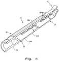
- FIG. 4is a perspective view of the second portion of the separable housing shown in FIG. 2 ;
- FIGS. 5-7are perspective views of the orthopaedic driver handle according to the present invention illustrating the disassembly of the orthopaedic driver handle.
- an orthopaedic driver handle 10that generally includes a drivetrain 12 , which has a driven end 14 opposite a driving end 16 and defines a longitudinal axis LA, and a separable housing 18 that partially covers the drivetrain 12 .
- the driven end 14 of the drivetrain 12may be a shank, or another connecting member, which connects to a source of rotational motion, such as a power drill (not shown).
- the driving end 16may be rotatably connected to an instrument connector 20 that connects to an orthopaedic end effector, such as a reamer head (not shown). While the driving end 16 is shown as being flared, any configuration of a driving end can be chosen that can rotatably couple to an instrument connector 20 and/or end effector.
- the drivetrain 12will transfer the rotational motion from the drill to the orthopaedic end effector.
- the longitudinal axis LAis the axis about which the drivetrain 12 rotates, as shown in FIG. 1 .
- the separable housing 18that generally includes a first portion 22 and a second portion 24 .
- the separable housing 18can include more than two portions, i.e. three portions, four portions, etc.
- the first portion 22can have locking features in the form of grooves 26 that correspond with locking features in the form of tabs 28 on the second portion 24 .
- the grooves 26can be formed adjacent to the circumferential edge 30 of the first portion 22
- the tabs 28can be formed adjacent to the circumferential edge 32 of the second portion 24 .
- the grooves 26 and tabs 28are shown to be machined from their respective portions 22 and 24 .
- the grooves 26 and tabs 28may be formed of a different material and/or be individually attached as separate members.
- the grooves 26 and tabs 28may also simply be in the form of one groove and one corresponding tab.
- the grooves 26each have an inner wall 26 A and a bottom surface 26 B.
- the inner wall 26 A of the grooves 26can extend parallel to the circumferential edge 30 of the first portion 22 .
- the bottom surface 26 B of the grooves 26can support at least one ramped feature 34 that has an outer surface 34 A and an inner surface 34 B.
- Each respective outer surface 34 A of the ramped features 34can be aligned flush with the circumferential edge 30 .
- the tabs 28can extend outwardly from the circumferential edge 32 of the second portion 24 .
- the tabs 28have an outer surface 28 A that is parallel to the circumferential edge 32 .
- the tabs 28can include at least one locking protrusion 36 that has an outer surface 36 A and an inner surface 36 B. Each outer surface 36 A of the locking protrusion 36 can align flush with the outer surface 28 A of the tabs 28 .
- the tabs 28can have a series of locking protrusions 36 that form an appearance of alternating plateaus and valleys.
- the locking protrusions 36are disposed to pass between the ramped features 34 and fit within the grooves 26 of the first portion 22 .
- first portion 22 and the second portion 24can each include an elongated straight region 38 and an angled region 40 .
- the elongated region 38can be substantially parallel to the longitudinal axis LA.
- the elongated region 38may include spaces to accommodate the drivetrain 12 , bushings and/or bearings.
- the angled region 40defines an angled axis AA that is oriented at a transverse angle relative to the longitudinal angle LA, as shown in FIG. 1 .
- the angled region 40may include spaces to accommodate the instrument connector 20 , bushings and or bearings.
- the separable housing 18may include a gripping feature in the form of a plurality of scallops 42 on the outer surface of the separable housing 18 for improving a user's tactile grip during the surgical procedure.
- the scallops 42as shown in FIG. 1 , can be parallel to the longitudinal axis LA.
- the scallops 42can be created by forming valleys between two ridges in the outer surface of the separable housing 18 .
- the scallops 42can be oriented at an angle transverse to the longitudinal axis LA and may be formed by any pattern of undulations.
- the gripping featuremay be formed by a gripping texture or an abrasion on the outer surface of the separable housing 18 .
- the orthopaedic driver handle 10may also include a first locking member in the form of an annular collar 44 that is mated to the exterior of the separable housing 18 , as shown in FIG. 1 .
- the annular collar 44may include a second locking member in the form of a spring-loaded element, such as a spring pin 46 (shown in FIG. 2 ), to keep the annular collar 44 from slipping off of the separable housing 18 .
- the second locking membermay mate at a specified notch and/or ridge 48 (shown in FIG. 5 ) formed in the exterior surface of the separable housing 18 adjacent the driven end 16 , or at any desired location along the exterior of the separable housing 18 .
- the second locking membermay also be in the form of pins, clasps, threads and/or fasteners.
- the first and second portions 22 , 24are aligned so that the locking protrusions 36 of the tabs 28 can pass between the spaced ramped features 34 along the bottom surface 26 A of the grooves 26 .
- the first and second portions 22 , 24are then brought together so that their respective circumferential edges 30 , 32 touch each other.
- the outer surface 36 A of the locking protrusions 36abut the inner wall 26 A of the grooves 26
- the outer surface 34 A of the ramped features 34abut the circumferential edge 32 of the second portion 24 .
- the locking protrusions 36fit substantially within the grooves 26 , thereby being housed within the first portion 22 .
- the first portion 22is slid in a direction of the longitudinal axis LA. Once the first portion 22 is slid into place, each inner surface 36 B of the locking protrusions 36 abuts the corresponding inner surface 34 B of the ramped features 34 . Now, since the grooves 26 and tabs 28 have been interlocked, the first portion 22 and the second portion 24 cannot separate laterally outward and the first and second portions 22 , 24 are rotationally locked together. Then, the annular collar 44 is mated to the first and second portions 22 , 24 of the separable housing 18 , which interferes with sliding of the first and second portions 22 , 24 relative to one another and prevents them from unlocking.
- FIGS. 5-7there is shown an orthopaedic driver handle 10 according to the present invention as it undergoes disassembly.
- FIG. 5shows the beginning step of removing the annular collar 44 , which frees the first portion 22 and the section portion 24 to move in a direction of the longitudinal axis LA, with such sliding illustrated by arrows.
- FIG. 6illustrates the step of distally sliding the first portion 22 in a direction of the longitudinal axis LA to disengage the locking protrusions 36 of the tabs 28 from the ramped features 34 . Sliding the first portion 22 aligns the tabs 28 such that the locking protrusions 36 may pass outwardly along the bottom surface 26 B of the grooves 26 between the ramped features 34 .
- FIG. 6illustrates the first portion 22 has been moved in a direction toward the instrument connector 20 .
- FIG. 7illustrates the step of separating the first portion 22 from the second portion 24 .
- the first and second portions 22 , 24are free to separate from each other.
- the separable housing 18can be made having any desired shape.
- the separable housing 18may have a rectangular or hexagonal cross-section.
- the separable housing 18is shown to be angled at one end, as defined by the angled axis AA, however the separable housing 18 may be composed of an entirely straight member or a member that has multiple angles and curves.
- the first and second portions 22 , 24 of the separable housing 18may also connect to each other along an axis that is transverse to the longitudinal axis LA.
- an embodiment of the separable housing 18may be in the form of a multi-portion body that slides over a drive shaft, along the longitudinal axis LA, and connects by radially twisting or simply interlocking the portions along an axis that is perpendicular to the longitudinal axis LA.
Landscapes
- Health & Medical Sciences (AREA)
- Surgery (AREA)
- Life Sciences & Earth Sciences (AREA)
- Biomedical Technology (AREA)
- Medical Informatics (AREA)
- Orthopedic Medicine & Surgery (AREA)
- Veterinary Medicine (AREA)
- Engineering & Computer Science (AREA)
- Public Health (AREA)
- Heart & Thoracic Surgery (AREA)
- Nuclear Medicine, Radiotherapy & Molecular Imaging (AREA)
- Molecular Biology (AREA)
- Animal Behavior & Ethology (AREA)
- General Health & Medical Sciences (AREA)
- Dentistry (AREA)
- Oral & Maxillofacial Surgery (AREA)
- Surgical Instruments (AREA)
Abstract
Description
Claims (7)
Priority Applications (1)
| Application Number | Priority Date | Filing Date | Title |
|---|---|---|---|
| US14/853,332US10687852B2 (en) | 2015-09-14 | 2015-09-14 | Separable instrument driver handle |
Applications Claiming Priority (1)
| Application Number | Priority Date | Filing Date | Title |
|---|---|---|---|
| US14/853,332US10687852B2 (en) | 2015-09-14 | 2015-09-14 | Separable instrument driver handle |
Publications (2)
| Publication Number | Publication Date |
|---|---|
| US20170071631A1 US20170071631A1 (en) | 2017-03-16 |
| US10687852B2true US10687852B2 (en) | 2020-06-23 |
Family
ID=58256921
Family Applications (1)
| Application Number | Title | Priority Date | Filing Date |
|---|---|---|---|
| US14/853,332Active2037-07-02US10687852B2 (en) | 2015-09-14 | 2015-09-14 | Separable instrument driver handle |
Country Status (1)
| Country | Link |
|---|---|
| US (1) | US10687852B2 (en) |
Families Citing this family (5)
| Publication number | Priority date | Publication date | Assignee | Title |
|---|---|---|---|---|
| IT201900005272A1 (en)* | 2019-04-05 | 2020-10-05 | Limacorporate Spa | MILLING DEVICE FOR PROSTHETIC SURGERY |
| US11446073B2 (en)* | 2019-08-26 | 2022-09-20 | DePuy Synthes Products, Inc. | Flexible shaft support rod |
| IT202000005947A1 (en)* | 2020-03-19 | 2021-09-19 | Limacorporate Spa | GUIDED MILLING DEVICE FOR PROSTHETIC SURGERY |
| US11638653B2 (en)* | 2020-11-05 | 2023-05-02 | Warsaw Orthopedic, Inc. | Surgery instruments with a movable handle |
| CN117898788B (en)* | 2024-01-16 | 2025-02-18 | 北京和华瑞博医疗科技有限公司 | Curved acetabular file connecting rod, end effector and surgical robot |
Citations (24)
| Publication number | Priority date | Publication date | Assignee | Title |
|---|---|---|---|---|
| US2090885A (en) | 1935-04-12 | 1937-08-24 | Clark Charles Howard | Dental drilling instrument |
| US5643271A (en) | 1994-09-09 | 1997-07-01 | Sulzer Orthopedics Inc. | Angled orthopedic surfacer and guide |
| US5772436A (en) | 1995-07-05 | 1998-06-30 | Akira Matsui | Odontotherapeutic hand piece |
| US20040172036A1 (en) | 2003-02-27 | 2004-09-02 | Donald Dye | Angled acetabular reamer and method of use |
| US20050075660A1 (en)* | 2003-10-03 | 2005-04-07 | Chu Michael S. H. | Systems and methods for delivering a medical implant to an anatomical location in a patient |
| US7326198B2 (en) | 2000-06-24 | 2008-02-05 | Precimed S.A. | Remote release instrument holder for surgical use |
| US20090088757A1 (en) | 2007-10-02 | 2009-04-02 | Howmedica Osteonics Corp. | Acetabular reamer |
| US7537597B2 (en) | 2001-01-25 | 2009-05-26 | Linvatec Corporation | Storage package for coring reamer assembly |
| US7611515B2 (en) | 2002-09-13 | 2009-11-03 | Symmetry Medical, Inc. | Orthopaedic reamer driver for minimally invasive surgery |
| US7615053B2 (en)* | 2004-12-06 | 2009-11-10 | Aeolin, Llc | Surgical rongeur |
| US7699852B2 (en)* | 2003-11-19 | 2010-04-20 | Zimmer Spine, Inc. | Fenestrated bone tap and method |
| US7780669B2 (en) | 2002-04-30 | 2010-08-24 | Greatbatch Medical S.A. | Reamer spindle for minimally invasive joint surgery |
| US7819296B2 (en) | 2008-02-14 | 2010-10-26 | Ethicon Endo-Surgery, Inc. | Surgical stapling apparatus with retractable firing systems |
| US7976548B2 (en) | 2005-08-24 | 2011-07-12 | Greatbatch Medical S.A. | Surgical tool holder for facilitated sterilization |
| US8052690B2 (en) | 2004-01-13 | 2011-11-08 | Symmetry Medical, Inc. | Variable angle orthopaedic reamer driver |
| US20120184946A1 (en)* | 2007-10-05 | 2012-07-19 | Ethicon Endo-Surgery, Inc. | Ergonomic surgical instruments |
| US8323284B2 (en) | 2007-09-24 | 2012-12-04 | Symmetry Medical Manufacturing, Inc. | Adapter driver for orthopaedic reamer |
| US8348959B2 (en) | 2006-03-23 | 2013-01-08 | Symmetry Medical Manufacturing, Inc. | Angled surgical driver |
| US8398642B2 (en) | 2007-09-20 | 2013-03-19 | Symmetry Medical, Inc. | Dual reamer driver |
| US8403931B2 (en) | 2007-02-09 | 2013-03-26 | Christopher G. Sidebotham | Modular tapered hollow reamer for medical applications |
| US20130261632A1 (en) | 2012-03-29 | 2013-10-03 | Carl F. Livorsi | Surgical instrument and method of positioning an acetabular prosthetic component |
| US8806973B2 (en) | 2009-12-02 | 2014-08-19 | Covidien Lp | Adapters for use between surgical handle assembly and surgical end effector |
| US8834484B2 (en) | 2011-11-14 | 2014-09-16 | Biomet Manufacturing, Llc | Surgical instrument including angle adjustment mechanism and quick-connect mechanism |
| US8900246B2 (en) | 2011-04-06 | 2014-12-02 | DePuy Synthes Products, LLC | Proximal trial instrument for use during an orthopaedic surgical procedure to implant a revision hip prosthesis |
- 2015
- 2015-09-14USUS14/853,332patent/US10687852B2/enactiveActive
Patent Citations (24)
| Publication number | Priority date | Publication date | Assignee | Title |
|---|---|---|---|---|
| US2090885A (en) | 1935-04-12 | 1937-08-24 | Clark Charles Howard | Dental drilling instrument |
| US5643271A (en) | 1994-09-09 | 1997-07-01 | Sulzer Orthopedics Inc. | Angled orthopedic surfacer and guide |
| US5772436A (en) | 1995-07-05 | 1998-06-30 | Akira Matsui | Odontotherapeutic hand piece |
| US7326198B2 (en) | 2000-06-24 | 2008-02-05 | Precimed S.A. | Remote release instrument holder for surgical use |
| US7537597B2 (en) | 2001-01-25 | 2009-05-26 | Linvatec Corporation | Storage package for coring reamer assembly |
| US7780669B2 (en) | 2002-04-30 | 2010-08-24 | Greatbatch Medical S.A. | Reamer spindle for minimally invasive joint surgery |
| US7611515B2 (en) | 2002-09-13 | 2009-11-03 | Symmetry Medical, Inc. | Orthopaedic reamer driver for minimally invasive surgery |
| US20040172036A1 (en) | 2003-02-27 | 2004-09-02 | Donald Dye | Angled acetabular reamer and method of use |
| US20050075660A1 (en)* | 2003-10-03 | 2005-04-07 | Chu Michael S. H. | Systems and methods for delivering a medical implant to an anatomical location in a patient |
| US7699852B2 (en)* | 2003-11-19 | 2010-04-20 | Zimmer Spine, Inc. | Fenestrated bone tap and method |
| US8052690B2 (en) | 2004-01-13 | 2011-11-08 | Symmetry Medical, Inc. | Variable angle orthopaedic reamer driver |
| US7615053B2 (en)* | 2004-12-06 | 2009-11-10 | Aeolin, Llc | Surgical rongeur |
| US7976548B2 (en) | 2005-08-24 | 2011-07-12 | Greatbatch Medical S.A. | Surgical tool holder for facilitated sterilization |
| US8348959B2 (en) | 2006-03-23 | 2013-01-08 | Symmetry Medical Manufacturing, Inc. | Angled surgical driver |
| US8403931B2 (en) | 2007-02-09 | 2013-03-26 | Christopher G. Sidebotham | Modular tapered hollow reamer for medical applications |
| US8398642B2 (en) | 2007-09-20 | 2013-03-19 | Symmetry Medical, Inc. | Dual reamer driver |
| US8323284B2 (en) | 2007-09-24 | 2012-12-04 | Symmetry Medical Manufacturing, Inc. | Adapter driver for orthopaedic reamer |
| US20090088757A1 (en) | 2007-10-02 | 2009-04-02 | Howmedica Osteonics Corp. | Acetabular reamer |
| US20120184946A1 (en)* | 2007-10-05 | 2012-07-19 | Ethicon Endo-Surgery, Inc. | Ergonomic surgical instruments |
| US7819296B2 (en) | 2008-02-14 | 2010-10-26 | Ethicon Endo-Surgery, Inc. | Surgical stapling apparatus with retractable firing systems |
| US8806973B2 (en) | 2009-12-02 | 2014-08-19 | Covidien Lp | Adapters for use between surgical handle assembly and surgical end effector |
| US8900246B2 (en) | 2011-04-06 | 2014-12-02 | DePuy Synthes Products, LLC | Proximal trial instrument for use during an orthopaedic surgical procedure to implant a revision hip prosthesis |
| US8834484B2 (en) | 2011-11-14 | 2014-09-16 | Biomet Manufacturing, Llc | Surgical instrument including angle adjustment mechanism and quick-connect mechanism |
| US20130261632A1 (en) | 2012-03-29 | 2013-10-03 | Carl F. Livorsi | Surgical instrument and method of positioning an acetabular prosthetic component |
Also Published As
| Publication number | Publication date |
|---|---|
| US20170071631A1 (en) | 2017-03-16 |
Similar Documents
| Publication | Publication Date | Title |
|---|---|---|
| US10687852B2 (en) | Separable instrument driver handle | |
| US11806023B2 (en) | Orthopedic reamer for bone preparation, particularly glenoid preparation | |
| US6409732B1 (en) | Tool driver | |
| KR101271164B1 (en) | Spinal fixation system instrumentation and method of using same | |
| US9198672B2 (en) | Dual reamer driver | |
| JP2019051346A (en) | System and method for inverted shoulder implant | |
| JP6647279B2 (en) | Motorized surgical handpiece with chuck to facilitate alignment of cutting accessory mounted on tool | |
| US5295992A (en) | Patella cutting system | |
| US9936960B2 (en) | Detachable orthopaedic reamer handle | |
| AU2020276042B2 (en) | A set of tools for installing an implant | |
| KR20040104649A (en) | Reamer spindle for minimally invasive joint surgery | |
| JP2019506956A (en) | Orthopedic trial device | |
| CN108472047B (en) | Rotary cutter for preparing femoral bone for resurfacing hip implant | |
| AU2020395875A1 (en) | Adjustable reamer driver and impactor, and methods of preparing said driver and impactor | |
| US20170354424A1 (en) | Tool for cutting bone for surgical use | |
| US20180303495A1 (en) | Medical instrumentarium | |
| US9241811B2 (en) | Method and apparatus for implanting a prosthesis | |
| EP3485821B1 (en) | Orthopaedic reamer system | |
| US20170303936A1 (en) | Orthopaedic reamer connector | |
| EP3427676B1 (en) | Orthopaedic reamer connector | |
| CN114786596A (en) | Assembly and kit for reaming, method of assembling a reamer and use thereof in reaming an orthopaedic joint | |
| EP4223237B1 (en) | Acetabular cup remover assembly | |
| US11013519B2 (en) | Orthopaedic surgical instrument for manipulating a medical device |
Legal Events
| Date | Code | Title | Description |
|---|---|---|---|
| AS | Assignment | Owner name:SYMMETRY MEDICAL MANUFACTURING, INC., INDIANA Free format text:ASSIGNMENT OF ASSIGNORS INTEREST;ASSIGNORS:PHILLIPS, ALTON;CONLEY, JOHN;REEL/FRAME:036558/0555 Effective date:20150911 | |
| AS | Assignment | Owner name:WELLS FARGO BANK, NATIONAL ASSOCIATION, AS ADMINIS Free format text:SECURITY INTEREST;ASSIGNORS:TECOMET INC.;SYMMETRY MEDICAL INC.;SYMMETRY MEDICAL MANUFACTURING INC.;REEL/FRAME:042380/0915 Effective date:20170501 Owner name:WELLS FARGO BANK, NATIONAL ASSOCIATION, AS ADMINISTRATIVE AGENT, CALIFORNIA Free format text:SECURITY INTEREST;ASSIGNORS:TECOMET INC.;SYMMETRY MEDICAL INC.;SYMMETRY MEDICAL MANUFACTURING INC.;REEL/FRAME:042380/0915 Effective date:20170501 | |
| AS | Assignment | Owner name:JEFFERIES FINANCE LLC, AS COLLATERAL AGENT, NEW YO Free format text:SECURITY AGREEMENT;ASSIGNORS:TECOMET INC.;SYMMETRY MEDICAL MANUFACTURING INC.;SYMMETRY MEDICAL INC.;REEL/FRAME:042386/0154 Effective date:20170501 Owner name:JEFFERIES FINANCE LLC, AS COLLATERAL AGENT, NEW YORK Free format text:SECURITY AGREEMENT;ASSIGNORS:TECOMET INC.;SYMMETRY MEDICAL MANUFACTURING INC.;SYMMETRY MEDICAL INC.;REEL/FRAME:042386/0154 Effective date:20170501 | |
| STPP | Information on status: patent application and granting procedure in general | Free format text:ADVISORY ACTION MAILED | |
| STPP | Information on status: patent application and granting procedure in general | Free format text:DOCKETED NEW CASE - READY FOR EXAMINATION | |
| STPP | Information on status: patent application and granting procedure in general | Free format text:NON FINAL ACTION MAILED | |
| STPP | Information on status: patent application and granting procedure in general | Free format text:RESPONSE TO NON-FINAL OFFICE ACTION ENTERED AND FORWARDED TO EXAMINER | |
| STPP | Information on status: patent application and granting procedure in general | Free format text:FINAL REJECTION MAILED | |
| STPP | Information on status: patent application and granting procedure in general | Free format text:RESPONSE AFTER FINAL ACTION FORWARDED TO EXAMINER | |
| STPP | Information on status: patent application and granting procedure in general | Free format text:NOTICE OF ALLOWANCE MAILED -- APPLICATION RECEIVED IN OFFICE OF PUBLICATIONS | |
| STPP | Information on status: patent application and granting procedure in general | Free format text:PUBLICATIONS -- ISSUE FEE PAYMENT VERIFIED | |
| STCF | Information on status: patent grant | Free format text:PATENTED CASE | |
| AS | Assignment | Owner name:PNC BANK, NATIONAL ASSOCIATION, NEW YORK Free format text:SECURITY INTEREST;ASSIGNORS:TECOMET INC.;SYMMETRY MEDICAL MANUFACTURING INC.;SYMMETRY MEDICAL INC.;REEL/FRAME:064236/0110 Effective date:20230707 Owner name:SYMMETRY MEDICAL INC., INDIANA Free format text:RELEASE BY SECURED PARTY;ASSIGNOR:WELLS FARGO BANK, NATIONAL ASSOCIATION, AS ADMINISTRATIVE AGENT;REEL/FRAME:064239/0266 Effective date:20230707 Owner name:SYMMETRY MEDICAL MANUFACTURING INC., INDIANA Free format text:RELEASE BY SECURED PARTY;ASSIGNOR:WELLS FARGO BANK, NATIONAL ASSOCIATION, AS ADMINISTRATIVE AGENT;REEL/FRAME:064239/0266 Effective date:20230707 Owner name:TECOMET INC., MASSACHUSETTS Free format text:RELEASE BY SECURED PARTY;ASSIGNOR:WELLS FARGO BANK, NATIONAL ASSOCIATION, AS ADMINISTRATIVE AGENT;REEL/FRAME:064239/0266 Effective date:20230707 Owner name:SYMMETRY MEDICAL INC., INDIANA Free format text:RELEASE BY SECURED PARTY;ASSIGNOR:JEFFERIES FINANCE LLC, AS COLLATERAL AGENT;REEL/FRAME:064239/0203 Effective date:20230707 Owner name:SYMMETRY MEDICAL MANUFACTURING INC., INDIANA Free format text:RELEASE BY SECURED PARTY;ASSIGNOR:JEFFERIES FINANCE LLC, AS COLLATERAL AGENT;REEL/FRAME:064239/0203 Effective date:20230707 Owner name:TECOMET INC., MASSACHUSETTS Free format text:RELEASE BY SECURED PARTY;ASSIGNOR:JEFFERIES FINANCE LLC, AS COLLATERAL AGENT;REEL/FRAME:064239/0203 Effective date:20230707 Owner name:HPS INVESTMENT PARTNERS, LLC, AS ADMINISTRATIVE AGENT, NEW YORK Free format text:SECURITY INTEREST;ASSIGNORS:TECOMET INC.;SYMMETRY MEDICAL MANUFACTURING INC.;SYMMETRY MEDICAL INC.;REEL/FRAME:064239/0169 Effective date:20230707 | |
| MAFP | Maintenance fee payment | Free format text:PAYMENT OF MAINTENANCE FEE, 4TH YEAR, LARGE ENTITY (ORIGINAL EVENT CODE: M1551); ENTITY STATUS OF PATENT OWNER: LARGE ENTITY Year of fee payment:4 |