US10687793B2 - Minimally invasive no touch (MINT) procedure for harvesting the great saphenous vein (GSV) and venous hydrodissector and retractor for use during the MINT procedure - Google Patents
Minimally invasive no touch (MINT) procedure for harvesting the great saphenous vein (GSV) and venous hydrodissector and retractor for use during the MINT procedureDownload PDFInfo
- Publication number
- US10687793B2 US10687793B2US16/039,115US201816039115AUS10687793B2US 10687793 B2US10687793 B2US 10687793B2US 201816039115 AUS201816039115 AUS 201816039115AUS 10687793 B2US10687793 B2US 10687793B2
- Authority
- US
- United States
- Prior art keywords
- hydrodissector
- gsv
- tip
- vascular target
- fluid
- Prior art date
- Legal status (The legal status is an assumption and is not a legal conclusion. Google has not performed a legal analysis and makes no representation as to the accuracy of the status listed.)
- Active
Links
Images


Classifications
- A—HUMAN NECESSITIES
- A61—MEDICAL OR VETERINARY SCIENCE; HYGIENE
- A61B—DIAGNOSIS; SURGERY; IDENTIFICATION
- A61B17/00—Surgical instruments, devices or methods
- A61B17/00008—Vein tendon strippers
- A—HUMAN NECESSITIES
- A61—MEDICAL OR VETERINARY SCIENCE; HYGIENE
- A61B—DIAGNOSIS; SURGERY; IDENTIFICATION
- A61B17/00—Surgical instruments, devices or methods
- A61B17/02—Surgical instruments, devices or methods for holding wounds open, e.g. retractors; Tractors
- A—HUMAN NECESSITIES
- A61—MEDICAL OR VETERINARY SCIENCE; HYGIENE
- A61B—DIAGNOSIS; SURGERY; IDENTIFICATION
- A61B17/00—Surgical instruments, devices or methods
- A61B17/02—Surgical instruments, devices or methods for holding wounds open, e.g. retractors; Tractors
- A61B17/0218—Surgical instruments, devices or methods for holding wounds open, e.g. retractors; Tractors for minimally invasive surgery
- A—HUMAN NECESSITIES
- A61—MEDICAL OR VETERINARY SCIENCE; HYGIENE
- A61B—DIAGNOSIS; SURGERY; IDENTIFICATION
- A61B17/00—Surgical instruments, devices or methods
- A61B17/32—Surgical cutting instruments
- A61B17/320016—Endoscopic cutting instruments, e.g. arthroscopes, resectoscopes
- A—HUMAN NECESSITIES
- A61—MEDICAL OR VETERINARY SCIENCE; HYGIENE
- A61B—DIAGNOSIS; SURGERY; IDENTIFICATION
- A61B17/00—Surgical instruments, devices or methods
- A61B17/32—Surgical cutting instruments
- A61B17/3203—Fluid jet cutting instruments
- A—HUMAN NECESSITIES
- A61—MEDICAL OR VETERINARY SCIENCE; HYGIENE
- A61B—DIAGNOSIS; SURGERY; IDENTIFICATION
- A61B90/00—Instruments, implements or accessories specially adapted for surgery or diagnosis and not covered by any of the groups A61B1/00 - A61B50/00, e.g. for luxation treatment or for protecting wound edges
- A61B90/30—Devices for illuminating a surgical field, the devices having an interrelation with other surgical devices or with a surgical procedure
- A—HUMAN NECESSITIES
- A61—MEDICAL OR VETERINARY SCIENCE; HYGIENE
- A61B—DIAGNOSIS; SURGERY; IDENTIFICATION
- A61B17/00—Surgical instruments, devices or methods
- A61B2017/00831—Material properties
- A61B2017/00902—Material properties transparent or translucent
- A61B2017/00907—Material properties transparent or translucent for light
- A—HUMAN NECESSITIES
- A61—MEDICAL OR VETERINARY SCIENCE; HYGIENE
- A61B—DIAGNOSIS; SURGERY; IDENTIFICATION
- A61B17/00—Surgical instruments, devices or methods
- A61B17/32—Surgical cutting instruments
- A61B17/320016—Endoscopic cutting instruments, e.g. arthroscopes, resectoscopes
- A61B17/32002—Endoscopic cutting instruments, e.g. arthroscopes, resectoscopes with continuously rotating, oscillating or reciprocating cutting instruments
- A61B2017/320024—Morcellators, e.g. having a hollow cutting tube with an annular cutter for morcellating and removing tissue
- A—HUMAN NECESSITIES
- A61—MEDICAL OR VETERINARY SCIENCE; HYGIENE
- A61B—DIAGNOSIS; SURGERY; IDENTIFICATION
- A61B17/00—Surgical instruments, devices or methods
- A61B17/32—Surgical cutting instruments
- A61B2017/320044—Blunt dissectors
- A—HUMAN NECESSITIES
- A61—MEDICAL OR VETERINARY SCIENCE; HYGIENE
- A61B—DIAGNOSIS; SURGERY; IDENTIFICATION
- A61B17/00—Surgical instruments, devices or methods
- A61B17/32—Surgical cutting instruments
- A61B2017/320056—Tunnelers
- A—HUMAN NECESSITIES
- A61—MEDICAL OR VETERINARY SCIENCE; HYGIENE
- A61B—DIAGNOSIS; SURGERY; IDENTIFICATION
- A61B17/00—Surgical instruments, devices or methods
- A61B17/32—Surgical cutting instruments
- A61B17/3203—Fluid jet cutting instruments
- A61B2017/32035—Fluid jet cutting instruments with gas or air
- A—HUMAN NECESSITIES
- A61—MEDICAL OR VETERINARY SCIENCE; HYGIENE
- A61B—DIAGNOSIS; SURGERY; IDENTIFICATION
- A61B90/00—Instruments, implements or accessories specially adapted for surgery or diagnosis and not covered by any of the groups A61B1/00 - A61B50/00, e.g. for luxation treatment or for protecting wound edges
- A61B90/30—Devices for illuminating a surgical field, the devices having an interrelation with other surgical devices or with a surgical procedure
- A61B2090/306—Devices for illuminating a surgical field, the devices having an interrelation with other surgical devices or with a surgical procedure using optical fibres
- A—HUMAN NECESSITIES
- A61—MEDICAL OR VETERINARY SCIENCE; HYGIENE
- A61B—DIAGNOSIS; SURGERY; IDENTIFICATION
- A61B90/00—Instruments, implements or accessories specially adapted for surgery or diagnosis and not covered by any of the groups A61B1/00 - A61B50/00, e.g. for luxation treatment or for protecting wound edges
- A61B90/30—Devices for illuminating a surgical field, the devices having an interrelation with other surgical devices or with a surgical procedure
- A61B2090/309—Devices for illuminating a surgical field, the devices having an interrelation with other surgical devices or with a surgical procedure using white LEDs
- A—HUMAN NECESSITIES
- A61—MEDICAL OR VETERINARY SCIENCE; HYGIENE
- A61B—DIAGNOSIS; SURGERY; IDENTIFICATION
- A61B2217/00—General characteristics of surgical instruments
- A61B2217/002—Auxiliary appliance
- A61B2217/007—Auxiliary appliance with irrigation system
- A—HUMAN NECESSITIES
- A61—MEDICAL OR VETERINARY SCIENCE; HYGIENE
- A61B—DIAGNOSIS; SURGERY; IDENTIFICATION
- A61B90/00—Instruments, implements or accessories specially adapted for surgery or diagnosis and not covered by any of the groups A61B1/00 - A61B50/00, e.g. for luxation treatment or for protecting wound edges
- A61B90/36—Image-producing devices or illumination devices not otherwise provided for
- A61B90/361—Image-producing devices, e.g. surgical cameras
Definitions
- Atherosclerosisdirectly leads to coronary artery disease (CAD), which is the leading cause of death in the United States today.
- Coronary artery bypass graftingmay be described simply as a procedure for bypassing severely damaged or non-functional coronary arteries using a grafted portion of a healthy vein or artery harvested from the patient under treatment, such as the great saphenous vein (GSV), explained in greater detail below.
- GSVgreat saphenous vein
- Atherosclerosisalso is the cause of peripheral arterial disease (PAD), which leads to significant disability, increased amputation rates, and death.
- a second epidemic which is present in the United Statesis a very high incidence of significant varicose veins.
- This patent applicationdiscloses an improvement over the known endoscopic vein harvest (EVH) methods presently used to harvest the GSV for use in CABG procedures in a way that increases long term patency of the grafted portions as well as an improvement in the treatment of varicose veins that preserves the GSV in the body of the patient under treatment so that it will be available in an optimized state for harvesting in the future, if required.
- EHendoscopic vein harvest
- a minimally invasive method for dissecting a greater saphenous vein (GSV) from surrounding tissuescomprises inserting one of a needle and a hydrodissector into a patient's body so that a tip of the one of the needle and the hydrodissector is placed in a predetermined position adjacent to the GSV to be dissected from surrounding tissues, and injecting fluid at a substantially constant volumetric flow rate from the one of the needle and the hydrodissector while moving the one of the needle and the hydrodissector along a predetermined length of the GSV to cause dissection of the GSV from the surrounding tissues, wherein hydrodissected GSV is suitable for subsequent harvesting for use in surgical bypass procedures.
- the predetermined position adjacent the GSVis 1-2 mm away from an upper surface of the GSV closest to the patient's skin or 1-2 mm away from a lower surface of the GSV furthest from the patient's skin.
- the fluid injected in the injecting stepcomprises tumescent fluid including one or more of: isotonic sodium bicarbonate solution, Balanced Salt Solution with a pH of 7.4, isotonic saline solution, Plasma Lyte A solution, and an endothelial damage inhibitor solution comprising glutathione, ascorbic acid and L-arginine.
- the tumescent fluidfurther comprises one or more medications including one or more of: aspirin, low-molecular weight heparin, one or more vasodilators, nitroglycerine, Endothelin A receptor antagonist, folic acid, angiotensin II receptor antagonist, Spermine/NO, Losartan, Perilyl alcohol, Superoxide dismutase, Antitissue factor antibody, Verapamil, Ursolic acid. Rapamycin, Azathioprin, Paclitaxel, C-type natriuretic peptide, Leoligin, Papaverine, platelet rich plasma and stem cells. In some embodiments, these medications may be applied to the GSV after performing the hydrodissection.
- these medicationsmay be applied to the GSV after performing the hydrodissection.
- the GSVis hydrodissected from the surrounding tissues using one or more needles, and the inserting and injection steps are successively performed for each of a plurality of portions of a length of the GSV to cause dissection the respective portion of the length of the GSV from the surrounding tissues.
- a plurality of needlesare used, and each respective portion of the length of the GSV is hydrodissected from the surrounding tissues using a respective one of the plurality of needles.
- the steps of inserting and injectingare performed under one or more of: (1) ultrasound guidance for visualizing the one of the needle and the hydrodissector and (2) direct vision of the one of the needle and the hydrodissector using an image capturing device provided on or in proximity with the one of the needle and the hydrodissector.
- the ultrasound guidance for visualizing one of the needle and hydrodissectormay be performed using a portable ultrasound device.
- direct visionthe direct vision may be obtained by capturing live images using the image capturing device provided at the tip of the hydrodissector.
- the minimally invasive methodfurther comprises, before performing the inserting and injecting steps, making an incision in a patient's extremity; and positioning a barrier with an access port through the incision so as to cover and seal the incision, wherein the inserting step comprises inserting the one of the needle and the hydrodissector through the access port into the predetermined position adjacent the GSV to be dissected from the surrounding tissues.
- the barrieris formed from fluid-tight material and comprises one of a diaphragm and a tissue occluder, and the access port comprises a fluid-tight one way valve.
- the present inventionis also directed to a surgical bypass method that includes the above minimally invasive method, and further includes harvesting the hydrodissected GSV by exposing the hydrodissected GSV, dividing side branches of the hydrodissected GSV and dividing proximal and distal ends of the hydrodissected GSV, and using harvested GSV for bypass surgery.
- the harvesting stepfurther comprises lifting the hydrodissected GSV after exposing the hydrodissected GSV and prior to dividing the side branches.
- the present inventionis also directed to an ambulatory selective varicose vein ablation method comprising the above minimally invasive method and further including exposing the hydrodissected GSV; and ligating incompetent perforator and varicosed vein side branches.
- the ambulatory selective varicose vein ablation methodmay further include applying drug eluting stents to the hydrodissected GSV and ligated vein side branches for delivering one or more of drug therapy, stem cell therapy and gene therapy to the GSV.
- the present inventionis further directed to harvesters and hydrodissectors used for the above methods.
- the inventionprovides a harvester for harvesting a vein, the harvester comprising a handle, a blade extending at an angle from the handle, and one or more hook-shaped attachments configured to couple with the blade so as to protrude from a surface of the blade, the one or more hook-shaped attachments being configured for lifting of a vein during a vein harvesting procedure.
- the hook-shaped attachmentmay be a C-shaped attachment or a U-shaped attachment, and may be detachable from the blade.
- the bladeincludes a plurality of coupling mechanisms along a length of the blade, each of the coupling mechanisms being configured to selectively couple with one of the hook-shaped attachments.
- the bladehas a first surface facing away from the handle and an opposing second surface, and the one or more hook-shaped attachments are configured to couple to the first surface of the blade.
- the bladecomprises a tubular shaft and a spoon-shaped tip at a distal end of the tubular shaft and the one or more hook-shaped attachments are configured to couple to one or more of the tubular shaft and the spoon-shaped tip.
- the harvester of the present inventionmay also include one or more ports provided at the distal end of the tubular shaft, each of the one or more ports is configured to be coupled to one of a fluid supply, a gas supply and a vacuum.
- the harvesterfurther includes an image capturing assembly for capturing images of an operating field, with the image capturing assembly including an image capturing device provided at a tip of the blade.
- the tip of the blademay be spoon-shaped including a concave surface and an opposing convex surface, and the image capturing device may be provided on the concave surface of the spoon-shaped tip.
- the present inventionprovides a harvester for harvesting a vein, the harvester comprising a handle, a blade extending at an angle from the handle and having a spoon-shaped tip at a distal end of the blade, the spoon-shaped tip including a concave surface and a convex surface, and an image capturing assembly for capturing images of an operating field, the image capturing assembly including an image capturing device provided on the concave surface of the spoon-shaped tip.
- the present inventionprovides a harvesting retractor for harvesting a vein, which includes a handle, a blade extending at an angle from the handle and having a first surface facing away from the handle and an opposing second surface, and a tunnel formed on the first surface of the blade and extending along a portion of the blade configured for accommodating a direct visualization device therein.
- the harvesting retractormay also include a channel along the first surface of the blade and a channel cover covering the channel, wherein the channel is configured for one or more of: removal of fluids from operating field, removal of debris from the operating field, removal of smoke from the operating field, injecting fluid into the operating field and infusing gas into the operating field, and wherein the channel and the tunnel extend along the first surface of the blade and are parallel to one another.
- the present inventionalso provides a hydrodissector for hydrodissecting a vein, the hydrodissector comprising a handle, a shaft extending from the handle at an angle and including a tip at a distal end thereof, at least one port configured to be coupled to a fluid supply for supplying fluid at a substantially constant pressure, and provided at the distal end of the shaft, and an image capturing assembly configured to provide direct visualization of the vein during hydrodissection.
- the image capturing assemblycomprises an image capture device encased by the tip of the shaft.
- the image capture deviceincludes a lens, an image sensor and/or one or more light sources.
- the image capturing assemblymay also include a power source for powering the image capture device, said power source being provided in one of the tip, the shaft and the handle.
- the tip of the shaftis transparent and the image capture device is positioned inside the tip so that an optical axis of the image capture device is angled relative to a lengthwise axis of the tip so as to allow direct viewing of the vein to be hydrodissected.
- the tiphas a substantially cylindrical shape and an angled end so that a first surface of the tip is longer than an opposing second surface of the tip.
- the at least one portis external and adjacent to the first surface of the tip, while in other embodiments, the at least one port is provided in the tip and is configured to be coupled the fluid supply via one of the shaft and a conduit extending inside the shaft.
- the at least one portmay include a first port configured to be coupled to a fluid supply and having a size between 14 and 22 gauge, and in some embodiments, a second port may be provided for coupling to a vacuum.
- the tipis configured to rotate relative to the shaft.
- the shaftis configured to rotate relative to the handle.
- the tip of the shaftis removable from a body of the shaft and interchangeable with one or more second tips, while in other embodiments the shaft is removable from the handle and interchangeable with one or more second shafts.
- the second tipmay be a spoon-shaped tip configured for retracting tissues and for harvesting the vein, and a second image capturing device may be provided on the spoon-shaped tip.
- the second shaftmay include a second tip, such as a spoon-shaped tip, and may be configured to releasably couple with the handle and to convert the hydrodissector into a harvester for harvesting the vein, and may have a second image capturing device is provided on the second tip.
- a second tipsuch as a spoon-shaped tip
- FIGS. 1 -A- 1 Bshow a process of hydrodissecting the GSV using one needle to hydrodissect multiple sections of the GSV;
- FIGS. 2A-2Bshow another process of hydrodissecting the GSV using one needle to hydrodissect multiple sections of the GSV;
- FIGS. 3A-3Bshow another process of hydrodissecting the GSV using multiple needles to hydrodissect respective sections of the GSV;
- FIG. 4shows another process of hydrodissecting the GSV using a venous hydrodissector
- FIGS. 5A-5Cshow an exemplary venous hydrodissector for use in the process of FIG. 4 ;
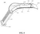
- FIG. 6shows a retractor for use during harvesting the GSV
- FIG. 7shows another version of a retractor for use during the harvesting of the GSV
- FIGS. 8A and 8Bshow a front view of different versions of the retractor of FIG. 7 ;
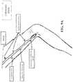
- FIG. 9Ashows a GSV after undergoing an endoscopic ASVAL procedure
- FIG. 9Bshows a GSV after undergoing the Endoscopic ASVAL procedure and having bioabsorbable drug eluting stents applied thereto;
- FIG. 10shows an exemplary visualization device that uses a pediatric cystoscope
- FIG. 11shows a 7F introducer sheath suitable for use with the visualization device of FIG. 10 ;
- FIG. 12shows the visualization device used with the introducer sheath
- FIG. 13shows an end portion of the visualization device extending through an end of the introducer sheath and fluid being pumped through the introducer sheath around the visualization device;
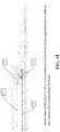
- FIG. 14shows a retractor of the present invention used with the visualization device of FIG. 10 ;
- FIG. 15shows a side view of another exemplary hydrodissector for use with the procedure shown in FIG. 4 ;
- FIG. 16shows a close-up of the side view of the hydrodissector of FIG. 15 at its distal end
- FIG. 17shows a cross-sectional view of the hydrodissector's tip, taken along a dashed line in FIG. 16 ;
- FIG. 18shows an end view of the hydrodissector of FIG. 15 in situ, surrounded by connective tissue above the GSV;
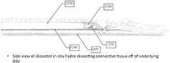
- FIG. 19shows an end view of the hydrodissector of FIG. 15 in situ while dissecting connective tissue off the underlying GSV;
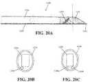
- FIGS. 20A-20Cshow another exemplary version of the hydrodissector for use with the procedure shown in FIG. 4 ;
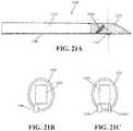
- FIGS. 21A-21Cshow another exemplary version of the hydrodissector for use with the procedure shown in FIG. 4 ;
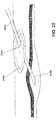
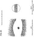
- FIGS. 22-25show another version of the procedure for hydrodissecting the GSV.
- FIG. 26shows an exemplary split screen visualization which includes an ultrasound view of hydrodissection and a direct visualization view.
- CABGcoronary artery bypass surgery
- CADcoronary artery disease
- the EVH techniqueemploys a 2 cm incision at the level of the knee.
- the GSVis exposed through this incision and bluntly dissected from its surrounding connective tissue, including a well-developed laminar ligament which attaches the GSV to the underlying muscular fascia.
- This laminar ligamenthas been anatomically well defined and arises from the adventitia of the GSV.
- EVHhas greatly reduced the incidence of leg wound complications, several recent articles have suggested that the patency rates of the GSV harvested by EVH are inferior to those harvested by the open vein technique (OVH).
- the minimally invasive no touch (MINT) procedure of the present inventionprovides these advantages by effectively improving the patency rates of harvested GSVs without the local leg wound complications associated with the known “No Touch” harvesting technique.
- the MINT procedurealso provides for visualization of the vein during dissection and harvesting, thereby reducing or eliminating a risk of damaging the harvested GSV and making it easy for physicians to acquire the skill of harvesting the GSV.
- the MINT procedureutilizes the technique of hydrodissection to facilitate the harvesting of the GSV. It should be noted that the MINT procedure, including the hydrodissection and the harvesting of the GSV, can be readily applied to harvesting the GSV for CABG and for lower extremity bypass procedures.
- Hydrodissectionis a technique that has been used in microsurgical procedures such as DIEP flaps, robotic prostatectomy and dissection of ITA for CABG. It has been established that hydrodissection facilitates microvascular dissection while not affecting the patency of the microvascular pedicle itself.
- One difficulty in using hydrodissection for harvesting the GSVis the laminar ligament which attaches the GSV to the underlying muscular fascia and which typically requires a blunt force to divide it.
- the blunt force necessary to divide this ligament during the EVH procedurelikely contributes to endothelial damage to the GSV, which can result in reduced patency rates.
- the MINT procedurecontemplates performing hydrodissection several hours and preferably, several days, prior to harvesting the GSV at the time of CABG. Doing so allows for recovery of any endothelial damage done at the time of the hydrodissection.
- hydrodissectioncan be performed immediately before harvesting and excess fluid remaining after hydrodissection can be milked or suctioned from the tunnel along the GSV before harvesting the GSV.
- the inventive improved MINT procedureincludes bringing the candidate for CABG surgery to the catheterization lab (or an associated venous treatment facility) several hours and preferably, several days prior to the actual harvesting of the GSV.
- the candidateis placed with the lower extremity in a frog leg position and then subjected to duplex scanning of the GSV to be hydrodissected and utilized.
- Ultrasonic equipmentmay be used for evaluating the GSV and to trace its course using a marker, e.g., Sharpie® marking pen. After confirming that the GSV is of significant caliber and quality to be utilized, the lower extremity is prepped and sterilized with Chlorhexidine prep.
- Hydrodissection of the GSVis then carried out under sonographic control, such as by ultrasound guidance, using a needle, such as a 20 gauge or 22 gauge echogenic spinal needle and an infusion pump, or using a venous hydrodissector with a blunt tip or a pencil tip and an opening at the end, or a venous hydrodissector as described below and shown in FIGS. 10-13 and 15-21 .
- a needlesuch as a 20 gauge or 22 gauge echogenic spinal needle and an infusion pump
- a venous hydrodissectorwith a blunt tip or a pencil tip and an opening at the end, or a venous hydrodissector as described below and shown in FIGS. 10-13 and 15-21 .
- the GSVis exposed using a harvester (or retractor) described in more detail herein below, and is harvested by exposing and dividing side branches of the GSV and by dividing proximal and distal ends of the GSV.
- needle visualization or venous hydrodissector visualization using ultrasoundis used in order to insert the needle into a “sweet spot” in the extremity near the GSV without making contact with the GSV.
- the “sweet spot”is a predetermined position into which a tip of the needle or hydrodissector is inserted and is preferably about 1-2 mm distance away from the wall of the GSV. In other embodiments, the distance from the GSV may be smaller or greater than 1-2 mm.
- the “sweet spot”is located at or near the upper surface of the GSV, i.e., surface closest to the patient's skin, i.e., at a 12 o'clock location, while in other embodiments, the “sweet spot” is located to the side of the upper surface of the GSV, i.e., at about 20-90 degrees away from a plane connecting the center of the GSV and the top surface of the GSV in either direction (or between 9 o'clock and 12 o'clock or between 12 o'clock and 3 o'clock), and preferably at an angle of around 30-60 degrees from the plane connecting the center and the top surface of the GSV.
- the “sweet spot”may include other surfaces of the GSV, the top and side surfaces of the vein are the preferred locations because the GSV is held tightly to the fascia by a ligament. Since the GSV is surrounded by the fascia, needle or venous hydrodissector localization and placement of the needle or venous hydrodissector in the “sweet spot” is important so that fluid to be injected flows only into desired areas around the GSV.
- a second or subsequent hydrodissection passmay be performed with a second “sweet spot” being adjacent to the lower surface of the GSV, i.e., at or around a 6 o'clock location, which is opposite to the to the upper or top surface of the GSV.
- the first passmay be performed with the “sweet spot” being adjacent to the lower surface of the GSV and the second or subsequent pass may be performed with the second “sweet spot” being adjacent to the upper surface of the GSV.
- the second “sweet spot”may be to the side of the lower surface of the GSV (between 6 o'clock and 9 o'clock or between 6 o'clock and 3 o'clock).
- Fluid used during hydrodissectionis tumescent fluid, such as isotonic sodium bicarbonate with or without lidocaine, Balanced Salt Solution with a pH of around 7.4, such as Hank's Balanced Salt Solution manufactured by Thermo Fisher Scientific Isolyte Solution, or isotonic saline solution and/or any other suitable tumescent fluid solution.
- the tumescent fluidis DuraGraft (GALA Solution named after Glutathione, Ascorbic acid, L-Arginine) endothelial damage inhibitor solution manufactured by Somahlution, Inc. based in Jupiter, Fla.
- DuraGraftis used for tissue preservation in the GSV specifically for CABG, and is a preferred solution for performing the hydrodissection in order to reduce endothelial damage during this procedure.
- Examples of a GALA solution and a Hank's Balanced Salt Solution suitable for use as tumescent fluid during hydrodissectionare disclosed in U.S. Pat. No. 7,981,596.
- tumescent fluidincludes one or more medications for protecting the GSV and assisting in healing of the GSV.
- These one or more medicationsinclude one or more of aspirin, which protects the endothelium, heparin, such as local low-molecular weight heparin, and one or more vasodilators, such as venous vasodilators or combination dilators.
- Other medications that can be included in the tumescent fluidinclude but are not limited to one or more of the following: Nitroglycerine, Endothelin A receptor antagonist, Folic Acid, Angiotensin II receptor antagonist.
- tumescent fluidmay include platelet rich plasma or stem cells for strengthening the wall of the GSV, and in certain embodiments, gene therapy may be used as part of the tumescent fluid.
- the GSVis hydrodissected completely from the surrounding fascia. Complete hydrodissection may be necessary when the harvesting of the vein is performed immediately or shortly after the hydrodissection. In order to completely hydrodissect the GSV from the surrounding fascia, it may be necessary to perform multiple passes of hydrodissection along the length of the GSV, e.g., two passes of hydrodissection. For example, in a first hydrodissection pass, the needle or the hydrodissector is inserted into the “sweet spot” at or around the upper surface of the GSV (at or around 12 o'clock) and the GSV is hydrodissected by moving the needle or the hydrodissector along the upper surface of the GSV.
- the first hydrodissection passwill hydrodissect at least the upper half of the GSV (from 9 o'clock to 3 o'clock).
- the second hydrodissection passmay be performed by placing the needle or hydrodissector in the second “sweet spot” at or around the lower surface of the GSV (at or around 6 o'clock), which is opposite to the “sweet spot” at the upper surface so that the needle and the dissector is between the GSV and the muscular fascia.
- the second hydrodissection passproceeds by moving the needle or the hydrodissector along the lower surface of the GSV until the GSV is lifted off the muscular fascia.
- the locations of the “sweet spot” and the second “sweet spot”may be reversed or may be provided at different locations relative to the GSV.
- the GSVis partially hydrodissected so that all surrounding fascia is dissected from the vein except the laminar ligament, which can be dissected at a later time, under direct vision.
- the partially hydrodissected GSVremains tethered to some of the surrounding tissues. Partial hydrodissection of the GSV may result in less damage to the vein, thus extending the utility of the GSV and reducing its failure rate. Any remaining tissue can be hydrodissected under direct vision with either a spinal needle or venous hydrodissector.
- ultrasound guidanceis used for needle or venous hydrodissector localization and during hydrodissection. After the needle or venous hydrodissector is inserted and fluid is injected, the fluid makes a pocket around the GSV and the GSV may move during the hydrodissection. Ultrasound guidance allows the user to see the pocket forming around the vein and to see the tip of the needle or venous hydrodissector to ensure that the needle or venous hydrodissector does not damage the GSV.
- portable ultrasound equipmentis used for the ultrasound guidance.
- Terason® t3200 or t3300 Ultrasound System with Enhanced Needle Visualization (ENV)may be used for ultrasound guidance and for needle localization during the hydrodissection. The ENV helps the user to insert the needle or venous hydrodissector close to the GSV without coming into contact with the GSV.
- ENVEnhanced Needle Visualization
- the “sweet spot” for hydrodissection using one or more needlesis at the top of the GSV and about 1 mm away from the wall of the GSV.
- the “sweet spot”may be off to the side of the GSV.
- a predetermined length of the GSVe.g., about 10 cm of the GSV, is hydrodissected, after which the needle is removed, inserted at the next section of the GSV to be hydrodissected, the needle tip is visualized under ultrasound guidance, and after the needle tip is visualized in the “sweet spot,” fluid is again injected at high pressure to hydrodissect another predetermined length of the GSV. This process is repeated until the entire length of the GSV is hydrodissected.
- the amount of fluidmay be determined based on time of performing the hydrodissection, wherein the fluid is pumped at a constant volumetric flow rate (e.g., ml/m or ml/s).
- a constant volumetric flow ratee.g., ml/m or ml/s.
- about 100 ml of fluidis injected for about every 10 cm of the GSV being hydrodissected.
- typically hydrodissectionis performed 3 or 4 times along the length of the GSV, injecting between about 300 ml and 400 ml of fluid.
- Hydrodissection using one or more needlesmay be performed using one needle, such as an 18 gauge needle, a 20 gauge needle or a 22 gauge needle, e.g.
- the size of the needleis not limited to 18, 20 or 22 gauge sizes and other sizes may be used as long as sufficient fluid pressure is provided for hydrodissection.
- the size of the needlemay be between 14 gauge and 22 gauge.
- FIGS. 1A-1B, 2A-2B and 3A-3BThe process of hydrodissecting the GSV using one or more needles is illustrated in FIGS. 1A-1B, 2A-2B and 3A-3B .
- one needle 104is used for hydrodissection to hydrodissect four consecutive sections of the GSV 102 .
- the needle 104is inserted into each consecutive section of the GSV 102 in accordance with the circled numbers 1 - 4 , from the knee area and up to the groin area.
- FIG. 1Billustrates insertion of the needle 104 into the “sweet spot” adjacent to the GSV 102 prior to injecting the fluid to dissect the GSV from surrounding connective tissue.
- FIGS. 1A-1Billustrates insertion of the needle 104 into the “sweet spot” adjacent to the GSV 102 prior to injecting the fluid to dissect the GSV from surrounding connective tissue.
- FIGS. 3A-3Bthe order of insertion of the needle 104 into each consecutive section of the GSV 102 is opposite of FIG. 1A , starting from the groin area to the knee area.
- the insertion of the needle 104 into the “sweet spot” adjacent the GSV 102 in FIG. 2Bis similar to that of FIG. 1B .
- FIGS. 3A-3Bfour needles are used for hydrodissection of four consecutive sections of the GSV 102 .
- FIG. 3Aall four needles 104 are inserted into the “sweet spot” as shown in FIG. 3B , after which the fluid is injected through each needle to hydrodissect the corresponding section of the GSV from the surrounding connective tissue.
- hydrodissectionbeing performed on the GSV between the knee area and the groin area
- the same hydrodissection proceduremay also be performed between the knee area and the ankle of the lower extremity, and may be performed along the entire length of the GSV.
- the number of sections of the GSVis not limited to 3 or 4 and may be greater depending on the length of the GSV being hydrodissected.
- multiple hydrodissection passesmay be made where needed in order to achieve sufficient dissection of the GSV.
- hydrodissectionmay be performed by passing a narrow pencil-tip or a blunt-tipped venous hydrodissector under ultrasound guidance in the “sweet spot” through a small incision in the lower extremity and by pumping fluid, e.g., tumescent fluid, at high pressure through an opening at the tip of the venous hydrodissector to hydrodissect the GSV from surrounding connective tissues.
- the incision for inserting the venous hydrodissectoris formed around the knee area. In this way, the hydrodissection procedure requires only one incision for hydrodissecting the entire length of the GSV, including a portion between the knee area and the groin area and a portion between the knee area and the ankle area.
- the “sweet spot” for inserting the venous hydrodissectoris about 1 mm away from the GSV wall and at a location off to the side of the GSV, such as about 20-90 degrees in either direction from a plane connecting the top surface of the GSV and the center of the GSV. This way, the venous hydrodissector is introduced along the side of the vein transversely, reducing possibility of damage to the GSV.
- the venous hydrodissectoris introduced into the incision and after the venous hydrodissector tip is visualized in the “sweet spot,” fluid is injected at high pressure through the opening in the venous hydrodissector to hydrodissect the GSV from the surrounding connective tissue.
- the venous hydrodissectoris slid up along the GSV while injecting the fluid until the venous hydrodissector is fully inserted into the lower extremity along the GSV.
- the venous hydrodissectorAfter performing hydrodissection on one of the portions of the GSV, i.e., either the portion between the knee and the groin area or the portion between the knee and the ankle, the venous hydrodissector is removed and the same hydrodissection process may be performed on the other portion of the GSV through the same incision until the whole length of the GSV has been hydrodissected.
- the venous hydrodissectormay be introduced into the incision and fully inserted along the GSV to the other end of the GSV before visualizing the venous hydrodissector tip in the “sweet spot” and thereafter injecting fluid.
- the GSVis hydrodissected by pulling the venous hydrodissector back along the GSV.
- both portions of the GSVmay be hydrodissected through the same incision made in the knee area.
- the amount of fluidmay be determined based on the amount of time of performing the hydrodissection, wherein the fluid is pumped at a constant volumetric flow rate (e.g., ml/m or ml/s).
- a constant volumetric flow ratee.g., ml/m or ml/s.
- about 100 ml of fluidis injected for about every 10 cm of the GSV being hydrodissected, with around 300-400 ml of fluid injected for each portion of the GSV that is hydrodissected.
- FIG. 4The process of hydrodissecting the GSV using a venous hydrodissector is illustrated in FIG. 4 .
- a blunt tipped venous hydrodissector 204is used for hydrodissection to hydrodissect the one of two sections of the GSV 202 .
- the venous hydrodissector 204is inserted into a small incision, which is preferably formed in the knee area, and slid along the GSV 202 before placing the tip of the venous hydrodissector in the “sweet spot” and pumping tumescent fluid to hydrodissect the GSV from the surrounding tissue.
- the venous hydrodissector 204is slowly pulled out through the incision while hydrodissecting the GSV.
- the venous hydrodissector 204may be inserted into the incision and once the venous hydrodissector 204 tip is visualized in the “sweet spot”, the fluid is pumped to hydrodissect the GSV while sliding the venous hydrodissector 204 further along the GSV.
- FIG. 4shows the venous hydrodissector being inserted at the top of the GSV, in other embodiments, the venous hydrodissector is inserted along the side of the GSV, at an angle between 20 and 90 degrees from the plane connecting the center and the top of the GSV.
- multiple hydrodissection passesmay be made where needed in order to achieve sufficient dissection of the GSV, and in a second hydrodissection pass, the hydrodissector is visualized in the second “sweet spot” which is on the opposite side of the GSV from the “sweet spot” during the first hydrodissection pass (e.g., around 180 degrees relative to the “sweet spot” during the first hydrodissection pass).
- FIGS. 5A-5BAn example of a pencil tip venous hydrodissector suitable for hydrodissecting the GSV is shown in FIGS. 5A-5B .
- the venous hydrodissectormay be disposable or may be reusable.
- the venous hydrodissector 204has an elongated hollow substantially cylindrical body 206 and a pencil tip with a small opening 206 a therein.
- the length of the venous hydrodissector body 206can be between 10 and 30 cm long, and preferably between 15-25 cm long.
- the body of the venous hydrodissectormay be made from metallic materials, such as stainless steel or titanium, or from polymers and/or plastics with sufficient strength.
- the venous hydrodissector 206also includes a port 208 at the other end to which an infusion pump for pumping the fluid can be connected.
- the port 208can be a standard port, e.g., a Luer Lock port, to which any standard infusion pump may be coupled, or can be any other type of port.
- FIG. 5Bshows a close-up of the tip of the venous hydrodissector, showing a small opening 206 a formed at the tip.
- the opening 206 ashould be small enough to create sufficient pressure when the fluid is pumped therethrough. For example an opening sized between about 0.01 and 0.1 inches in diameter is suitable, and preferably between 0.01625 and 0.06 inches in diameter (14-22 gauge in size).
- the opening 206 ais about 0.02 inches to about 0.04 inches in diameter. In another illustrative embodiment, the opening is between 0.01625 and 0.024 inches in diameter.
- FIG. 5Cshows a close-up view of another venous hydrodissector tip which has a cone-shaped blunt tip. Like in FIG. 5B , the venous hydrodissector tip in FIG. 5C includes a small opening formed at the tip which is sized to create sufficient fluid pressure when fluid is pumped therethrough.
- a venous hydrodissector with a wider body and a larger opening at tipmay be used in combination with a needle.
- the needleis inserted into the venous hydrodissector so that the tip of the needle is covered by the tip of the venous hydrodissector.
- the needlemay be 14 gauge to 22 gauge in size, similar to the needle size used for the hydrodissection with a needle or a different size (gauge) needle.
- the infusion pumpis connected to the needle and pumps the fluid through the needle and out of the tip of the venous hydrodissector. This arrangement provides for sufficient fluid pressure to hydrodissect the GSV from the surrounding tissue while protecting the GSV from inadvertent damage by using the venous hydrodissector near the wall of the GSV.
- the inventive hydrodissection techniquesare optimized by use of the above-described venous hydrodissector.
- the venous hydrodissectoris configured with a pencil tip shaped or a cone-shaped tip and only one outflow port in the center of the tip in in order to ensure that the hydrodissection implemented by use of the venous hydrodissector occurs in parallel to the GSV.
- venous hydrodissectorminimizes force vectors that might result off-angle from the axial center of the linear extent of the GSV, for example, at 90° or less which is likely in conventional or standard infusion cannulas, which are known to have one or more outflow ports arranged in the cannula shaft, which create fluid paths substantially perpendicular to the cannula longitudinal axis. Fluid typically exits from these conventional ports creating force vectors perpendicular or slightly less than perpendicular to the longitudinal axis. The venous hydrodissector, therefore, reduces trauma that the hydrodissection procedure might impose on or to the GSV.
- Direct vision of the hydrodissection procedurecan be achieved by using a visualization device comprising a thin tube with a camera and a light source provided at one end and capable of connecting to a display panel (e.g., a tablet, a TV, a monitor, etc.) either using a wire or wirelessly.
- a visualization devicecomprising a thin tube with a camera and a light source provided at one end and capable of connecting to a display panel (e.g., a tablet, a TV, a monitor, etc.) either using a wire or wirelessly.
- the diameter of the tubeis about 2 mm or smaller.
- a port for infusion of liquidmay be included in the visualization device, which is used as a hydrodissector, while in other embodiments, no such port is included in order to reduce the diameter of the tube.
- a pediatric cystoscope, an angioscope or an endoscopemay be used as the visualization device. It is desired for the visualization device to be capable of capturing and transmitting clear images when exposed to liquids.
- An example of a suitable visualization device, which is a pediatric cystoscope,is shown in FIG. 10 , or a hydrodissector shown in FIGS. 15-19 .
- An example of a suitable angioscopeis an Olympus 2 mm angioscope. In this way, the MINT procedure can be performed utilizing currently available urologic or vascular equipment.
- the patientis first prepped and draped in the usual fashion with the donor lower extremity in the frog leg position.
- the tumescent fluidis injected just above the GSV, i.e., at 12 o'clock position, while in other embodiments, the tumescent fluid may be injected to the side of the GSV.
- This injection of the tumescent fluidcan be performed either percutaneously with ultrasound guidance, such as by using a portable ultrasound device, or under direct vision via a small incision, e.g., about 2 cm incision, that exposes the GSV. If a percutaneous injection is performed, the GSV is then exposed via a small incision, e.g., standard 2-3 cm incision, just below the tumescent fluid collection.
- FIG. 11shows a 7F introducer sheath suitable for use in this procedure.
- the introducer sheathincludes a side port which can be used for pumping fluid through the introducer sheath, as described in more detail below.
- the visualization devicesuch as a 2 mm pediatric cystoscope shown in FIG. 10 or a 2 mm angioscope
- FIG. 12shows a 2 mm cystoscope inserted into the 7F introducer sheath and demonstrates the positioning of the cystoscope relative to the 7F introducer sheath.
- the visualization devicee.g., cystoscope or angioscope
- the visualization deviceis connected to a display device, either by a wire or wirelessly
- the GSVis visualized directly on the monitor using the visualization device, e.g., cystoscope or angioscope.
- This techniqueallows the hydrodissection of the GSV to be performed under direct vision in real time.
- hydrodissectioncan be performed using one of the following techniques.
- the side port of the introducer sheathis attached to an infusion pump and fluid is infused via the introducer sheath at a sufficiently high rate to hydrodissect the GSV.
- Hydrodissectionis performed by moving the assembly of the visualization device with the introducer sheath, while pumping fluid along the length of the GSV or a portion of the GSV.
- FIG. 13shows an end portion of the visualization device extending through an end of the introducer sheath, and fluid being pumped through the introducer sheath around the visualization device.
- the visualization deviceallows the hydrodissection to be performed under direct vision in real time and eliminates the need for ultrasound guidance.
- a 7F introducer sheath like the one shown in FIG. 11 and a 2 mm cystoscope as shown in FIG. 10 or a 2 mm angioscopeare used for performing hydrodissection of the GSV.
- the size match of the 7F introducer and the 2 mm cystoscope/angioscope diameterallows just enough room for the fluid to travel in the sheath and around the cystoscope/angioscope and to exit the sheath as a jet of fluid with sufficient pressure to hydrodissect the GSV.
- the hydrodissection of the GSVis performed using a single assembly of the visualization device with the introducer sheath, with the assembly being advanced together as a unit along the GSV.
- the hydrodissectionis performed by advancing the cystoscope/angioscope and introducer sheath assembly proximally toward the groin.
- the direction in which the hydrodissection is performedmay be changed.
- the hydrodissection of the GSVis performed using a needle or the venous hydrodissector, as described above, with the fluid being pumped through the needle or the venous hydrodissector, and using the visualization device with the introducer sheath for direct visualization of the GSV and of the needle or the venous hydrodissector.
- the configuration of the needle or venous hydrodissector used in this variation of the hydrodissection procedureis the same as described above.
- the hydrodissectionmay be performed percutaneously using a needle, such as a 22 gauge spinal needle, under direct vision using the visualization device with the introducer sheath.
- This hydrodissection techniqueis similar to the hydrodissection technique described above using one or more needles or using the venous hydrodissector, but instead of ultrasound guidance, this procedure is performed under direct vision.
- a needle or a venous hydrodissectoris attached to the visualization device lengthwise, so that the visualization device and the needle or the venous hydrodissector extend side by side within the introducer sheath.
- the configuration of the needle or venous hydrodissector used in this variation of the hydrodissection procedureis the same as described above.
- the needle or the venous hydrodissectoris attached to an infusion pump so as to pump fluid therethrough.
- a 20 or 22 gauge blunt tipped spinal needlecan be attached lengthwise to a 2 mm cystoscope.
- the hydrodissection of the GSV in this techniqueis performed by advancing the visualization device with the attached needle or venous hydrodissector along the GSV as the fluid is being pumped, while leaving the introducer sheath in place.
- the hydrodissection of the GSVis performed under direct vision via the venous hydrodissector in real time.
- FIGS. 15-21Other types of hydrodissectors 1200 (or dissectors) that can be used for hydrodissection of the GSV are shown in FIGS. 15-21 .
- the hydrodissectors of FIGS. 15-21provide direct visualization of the GSV during hydrodissection by capturing and transmitting live images of the GSV and surrounding areas during the procedure.
- FIG. 15shows a general side view of the hydrodissector 1200 with a handle 1210 .
- the hydrodissector 1200includes an elongated tubular-shaped body 1220 having a proximal end 1220 a to which the handle 1210 is coupled and a distal end 1220 b to which an angled tip 1230 is coupled.
- the angled tip 1230is preferably formed from plastic, polymer material, glass, acrylic glass, e.g., poly(methylmethacrylate), Plexiglass, etc., or other suitable materials, and is transparent or translucent.
- the body 1220can be formed from a metallic material, e.g., stainless steel, aluminum, titanium, etc., or from a suitable plastic or polymer material.
- the handle 1210can be formed from plastic or polymer material or may be formed from metal or any other suitable material.
- the angled tip 1230has a substantially cylindrical shape and has an angled end so that a lower surface (first surface) of the tip 1230 is longer than an upper surface (second surface) of the tip 1230 .
- the angled end of the tip 1230is preferably sealed or closed so as to prevent fluids and debris from entering the angled tip 1230 through the angled end.
- the angled end of the tip 1230may be partially sealed/closed or may be open.
- the lower surface of the tip 1230would be positioned closer to the GSV than the upper surface during the hydrodissection procedure.
- the orientation of the angled tip 1230 relative to the orientation of the handle 1210may be adjustable.
- the handle 1210can be rotated around the tubular-shaped body 1220 and can be locked in one or more orientations, or the tubular-shaped body 1220 can be rotated relative to the handle 1210 .
- the locking orientations of the handle 1210may be flexible to allow an operator to select any suitable orientation, or the locking orientations of the handle 1210 may be predetermined so as to limit the number of orientations of the handle 1210 relative to the tubular-shaped body 1220 .
- one locking orientationmay be as shown in FIG. 15 where the handle is oriented in the same direction as the upper surface of the angled tip 1230 , and another locking orientation may be 180 degrees around the tubular-shaped body so that the handle 1210 is oriented in the same direction as the lower surface of the angled tip 1230 .
- Additional locking orientationsmay be provided in the hydrodissector.
- the angled tip 1230may be rotated relative to the tubular-shaped body 1220 and may be locked in one or more orientations, which may be predetermined or may be flexible so as to be selectable by the operator.
- Rotating the handle 1210 and/or the angled tip 1230 around the tubular-shaped body 1220allows the hydrodissector 1220 to be used to hydrodissect the GSV along the upper surface of the GSV, i.e., along the surface closest to the patient's skin, and to hydrodissect the GSV along the lower surface of the GSV, i.e., along the surface adjacent the muscular fascia.
- FIG. 16shows a close-up of the side view of the hydrodissector 1200 at its distal end
- FIG. 17shows a cross-sectional view of the hydrodissector's angled tip 1230 taken along a dashed line in FIG. 16
- the hydrodissector 1200includes at least one fluid port 1240 for injecting fluid therethrough to hydrodissect the GSV as described above.
- the at least one fluid port 1240includes a conduit that extends along the tubular-shaped body 1220 and is coupled to a fluid supply at a proximal end thereof (not shown) and has an injection opening 1241 at a distal end thereof.
- the proximal end of the conduit of the fluid port 1240may have a Luer Lock fitting or any other suitable fitting at its end to allow the fluid port 1240 to be connected to the fluid supply, e.g., tumescent fluid supply, gas supply, e.g., CO2 supply, and/or vacuum source.
- the injection opening 1241is preferably located at or near the angled end of the angled tip 1230 .
- the hydrodissector 1200includes two fluid ports 1240 a , 1240 b including conduits that extend substantially parallel to one another along the tubular-shaped body 1220 .
- the conduit of each portmay have a Luer Lock fitting or any other suitable fitting at its proximal end for connection to fluid supply, gas supply and/or vacuum source.
- the fluid ports 1240 a , 1240 bmay have the same size or may have different sizes from one another, and the sizes of the ports may vary between 14 and 22 gauge. In the illustrative embodiment shown in FIG.
- the fluid port 1240 ais smaller than the fluid port 1240 b , with the fluid port 1240 a having a 20 gauge size opening and the fluid port 1240 b having a 14 gauge size opening.
- the fluid port 1240 ais used for injecting tumescent fluid for hydrodissecting the GSV, as described above, and the fluid port 1240 b is used for suction of tumescent fluid after hydrodissection of the GSV.
- the smaller sized portmay be used for suction of fluid while the larger sized port is used for injection of fluid, or the ports may have the same size. In the embodiment of FIG.
- the conduits of the ports 1240 a , 1240 bare provided along a lower outer surface of the tubular-shaped body 1220 and along the outer lower surface of the angular tip 1230 .
- the ports 1240 a , 1240 bare spaced from one another so that each port 1240 a , 1240 b is provided along a different side of the lower outer surface of the tubular-shaped body 1220 and along a different side of the lower surface of the angled tip 1230 .
- the ports 1240 a , 1240 bmay be provided along the same side of the lower outer surface of the tubular-shaped body 1220 and the lower surface of the angled tip 1230 .
- one or both of the portsmay include a sealing or closing mechanism to close the port opening when not in use. In this way, when one of the ports is being used to inject fluid to hydrodissect the GSV, the fluid is prevented from escaping though the other port.
- Certain embodimentsmay include only one port 1240 , instead of two ports, for supplying fluid for hydrodissection of the GSV.
- the conduit of the single portmay extend along the lower outer surface of the tubular-shaped body 1220 and along the lower surface of the angled tip 1230 and may be centered or may be shifted to one of the sides relative to the tubular-shaped body and the tip.
- the positioning of the portdepends on the position of an image capture device 1250 and is made such that the port does not block the field of view of the image capture device.
- the hydrodissector 1200includes the image capture apparatus 1250 , such as a video camera or the like, disposed inside the angled tip 1230 .
- the image capture apparatus 1250is protected from fluids and debris during the hydrodissection of the GSV.
- the angled end of the angled tip 1230is closed or sealed, and thus, in such embodiments, the image capture apparatus 1250 is encapsulated or encased in the angled tip and protected from fluids and debris.
- the image capture apparatus 1250is configured to capture live images so as to visualize the GSV during the hydrodissection procedure.
- the live imagesmay be transmitted wirelessly from the image capture apparatus 1250 to a computer, a tablet or a suitable display, or may be transmitted through a wire, e.g., by a USB connection.
- the image capture apparatusis preferably an miniature camera so that it can be fitted within the angled tip 1230 .
- the image capture apparatusmay be a waterproof or non-waterproof, CMOS-based video camera with encapsulated lighting.
- the camerais a HD waterproof endoscope video camera probe with a small diameter of less than 1 inch, e.g., about 0.1-0.5 inch diameter, that includes a Hi-Vision or Super Hi-Vision CMOS sensor and has a resolution of 2.0 MP or higher.
- the camerapreferably has a focal distance between 0.5 and 4 inches. However, the focal distance of the camera may vary depending on its configuration and desired position within the angled tip 1230 .
- the camera of this exampleincludes one or more of a USB-C connection, a Micro USB connection, a Bluetooth® connection and/or a Wi-Fi connection for connecting with an external display, computer or tablet.
- the cameramay be a miniature cystoscope, angioscope or laparoscope camera.
- the cameramay be compatible with any operating system, such as Windows 7/8/10, Mac OS, Android system, etc. and may support a USB On-The-Go (USB OTG or OTG) and USB video device class (UVC) functions.
- the camerauses a lens carrier housing for enclosing the lens, and image sensor chip and/or lighting, such as the endoscope video cameras, and the lens carrier housing is attached to a surface of the angled tip of the hydrodissector or positioned within the angled tip.
- the cameramay be a one-piece assembly that incorporates the lens, the image sensor chip and/or the lighting, which can be molded into the angled tip or received in a cavity formed in the angled tip of the hydrodissector.
- the image capture apparatus 1250is positioned at an angle with respect to the lower surface of the angled tip 1230 , i.e., an optical axis of the camera is at an angle with respect to the lower surface of the angled tip 1230 , so that a camera lens and a camera sensor are provided at an angle with respect to the line of sight to the GSV which underlies the lower surface of the angled tip during hydrodissection.
- the angle of the image capture apparatus 1250may be between 15 and 60 degrees relative to the lower surface of the angled tip 1230 . In the illustrative embodiment of FIG. 16 , the image capture apparatus 1250 is positioned at about a 30 degree angle relative to the lower surface of the angled tip 1230 .
- This angled positioning of the image capture apparatus 1250allows for direct viewing of the GSV to be hydrodissected and during the hydrodissection procedure.
- the angle of the image capture apparatus 1250 relative to the lower surface of the angled tip 1230will depend on the distance of the image capture device 1250 from the injection opening 1241 of the fluid input port 1240 a and the field of view of the image capture apparatus 1250 .
- the angled tip 1230may also have one or more light sources, e.g., one or more LEDs, disposed therein.
- a plurality of LEDsmay be disposed around the image capture apparatus 1250 , or at least one LED may be disposed adjacent to the image capture apparatus 1250 .
- the LEDsare angled relative to the lower surface of the angled tip 1230 similarly to the image capture apparatus 1250 so as to direct light emitted from the LEDs in the same direction as the object being captured by the image capture apparatus 1250 .
- the power sourcesfor powering the image capture apparatus 1250 and/or the light source(s) and any connections or wiring necessary for connecting the power source(s) to the image capture apparatus 1250 and/or the light source(s) and for connecting the image capture apparatus 1250 with a display, a computer or tablet, if needed.
- the image capture apparatus 1250may include an internal power source, while in other embodiments, the power source may be disposed within the tubular-shaped body 1220 or within the handle 1210 .
- the connections or wiring to the power source and/or to the display, computer or tabletmay be provided through the tubular-shaped body 1220 and/or through the handle 1210 .
- FIGS. 18 and 19show the hydrodissector of FIGS. 15-17 being used during hydrodissection of the GSV along the top surface of the GSV.
- the hydrodissectoris surrounded by the connective tissue just above the GSV.
- the hydrodissectoris placed in the “sweet spot”, with the angled tip 1230 being preferably just above the top surface of the GSV, e.g., a few millimeters above the GSV, and the image capture apparatus 1250 is used for directly visualizing the hydrodissector 1200 in the “sweet spot” and for directly visualizing the GSV and the surrounding area.
- the hydrodissector 1200is moved along the length of the GSV while dissecting the connective tissue off the GSV in order to hydrodissect the entire length of the GSV.
- the GSVmay be hydrodissected using multiple hydrodissection passes, so that during the second hydrodissection pass, the hydrodissector 1200 is visualized adjacent the lower surface of the GSV, which is opposite to the upper surface of the GSV shown in FIGS.
- the handle 1210 or the angled tip 1230 of the hydrodissectoris rotated about 180 degrees relative to the tubular body so that during the second hydrodissection pass, the lower (longer) surface of the angular tip 1230 faces the GSV.
- FIGS. 20A-20C and 21A-21Cshow other versions of the hydrodissector 1200 that can be used for hydrodissecting the GSV.
- the hydrodissector 1200 in FIGS. 20A-20C and 21A-21Cis modified by providing the one or more ports 1240 that include conduits inside the tubular-shaped body 1220 .
- FIGS. 20A-20C and 21A-21Cshow other versions of the hydrodissector 1200 that can be used for hydrodissecting the GSV.
- the hydrodissector 1200 in FIGS. 20A-20C and 21A-21Cis modified by providing the one or more ports 1240 that include conduits inside the tubular-shaped body 1220 .
- the hydrodissector 1200includes the tubular-shaped body 1220 , the angled tip 1230 attached to the distal end of the tubular-shaped body 1220 , the image capture apparatus 1250 provided inside and enclosed by the angled tip 1230 and one or more ports 1240 for fluid supply, gas supply and/or vacuum.
- the image capture apparatus 1250is provided at an angle between 15 and 60 degrees relative to the lower surface of the angled tip 1230 .
- the conduits of the one or more ports 1240are provided within the tubular-shaped body 1220 and the difference between the embodiment of FIGS. 20A-C and FIG. 21A-C is the configuration of the one or more ports 1240 .
- FIGS. 20B and 20Cshow cross-sectional views of the hydrodissector 1200 in FIG. 20A taken along the dashed line in FIG. 20A .
- FIG. 20Bshows a cross-sectional view of a hydrodissector with one port 1240
- FIG. 20Cshows a cross-sectional view of a hydrodissector with two ports 1240 a and 1240 b .
- the ports 1240 , 1240 a , 1240 bpreferably have an opening of 14-22 gauge in size.
- the port 1240is preferably a fluid port for supplying tumescent fluid for hydrodissection of the GSV and has a size between 14 and 22 gauge, and preferably, 20 or 22 gauge.
- the ports 1240 a , 1240 bmay have the same size or may have different sizes.
- port 1240 amay be used as a fluid port for supplying tumescent fluid for hydrodissection of the GSV and may have a size between 14 and 22 gauge, and preferably, 20 or 22 gauge.
- the port 1240 bmay be used as a suction port and may have a larger size between 14 and 22 gauge, and preferably between 14 and 18 gauge.
- the port 1240 amay be used for suction and the port 1240 b may be used for fluid supply and may be sized as needed for these functions.
- one or both of the ports 1240 a , 1240 bmay be closed or sealed when not in use in order to prevent fluid from entering the unused port during the hydrodissection procedure.
- the port 1240 or the ports 1240 a , 1240 bare disposed on the inner lower surface of the angled tip 1230 and are shifted to the side away from the center.
- both portsmay be provided on the same side instead of being on different sides of the angled tip 1230 .
- the ports 1240 , 1240 a , 1240 bare positioned so as not to block the field of view of the image capture apparatus 1250 through the lower surface of the angled tip 1230 .
- the hydrodissector 1200has one or more ports 1240 including conduits which extend along the lower inner surface of the tubular-shaped body 1220 and along a portion of the angled tip 1230 . Each port 1240 is then directed through an opening 1243 in the lower surface of the angled tip 1230 to outside of the hydrodissector 1200 . The end of the port 1240 may extend downwardly from the opening or may be angled toward the distal end of the hydrodissector, as shown in FIG. 21A .
- 21Ashows the port 1240 extending through the opening 1243 in the lower surface of the angled tip 1230
- the openingmay be provided in the lower surface of the tubular body 1220 and the port 1240 would extend through the opening in the tubular body 1220 .
- the position of the openingwould depend on the desired position of fluid injection from the hydrodissector 1200 during the hydrodissection procedure.
- FIGS. 21B and 21Cshow cross-sectional views of the hydrodissector 1200 in FIG. 21A taken along the dashed line in FIG. 21A .
- FIG. 21Bshows a configuration of the hydrodissector 1200 with one port 1240
- FIG. 21Cshows a configuration of the hydrodissector 1200 with two ports 1240 a , 1240 b .
- the ports 1240 , 1240 a , 1240 bare shifted to the side away from the center so as not to block the view of the image capture apparatus 1250 through the angled tip 1230 .
- port sizes and usesare similar to those of FIGS. 20B and 20C and thus, detailed description thereof is omitted.
- FIGS. 20A-21Cshow at least one port 1240 extending along the lower surface of the body 1220 and the angled tip 1230
- fluidmay be supplied directly to the tubular-shaped body 1220 , without using a separate structure for the port, and a small opening may be provided in the angular tip for fluid injection therefrom.
- the opening sizeshould be such that fluid is injected from the opening with sufficient fluid pressure for hydrodissection of the GSV.
- the opening sizemay be between 14 and 22 gauge and preferably, 20 or 22 gauge.
- the openingmay be provided at the end of the angled tip, similar to FIG. 20A or may be provided in the lower surface of the angled tip, similar to FIG. 21A .
- FIGS. 15-17 and 20A-21Cshow the hydrodissector that uses the angled tip 1230
- the angled tip 1230may be removable from the body 1220 and may be interchangeable with other types of tips attachable to the body 1220 . Different tips may be used for different phases of the procedure, e.g., angled tip 1230 for hydrodissection of the GSV and other types of tips for harvesting of the GSV.
- the angled tip 1230may be removable from the body 1220 and may be replaced with a shovel-shaped or spoon-shaped tip. An example of a shovel-shaped or spoon-shaped tip is shown in FIGS.
- the camera and/or light source(s)may be positioned so as to face in a direction away from the handle and toward a distal end of the dissector (e.g., at about 90 degrees relative to the lower surface of the tip) or may be angled to face away from the concave surface of the shovel-shaped or spoon-shaped tip (e.g., at an angle between 90 and 180 degrees relative to the lower surface of the tip).
- the cameramay use a lens carrier housing that encloses the lens, the image sensor chip and/or lighting (e.g., LEDs) and the lens carrier is attached, either permanently or detachably, to the concave surface of the spoon-shaped tip.
- the cameramay be a one-piece assembly that incorporates the lens, the image sensor chip and/or the lighting, which can be molded into the spoon-shaped tip or received in a cavity formed in the spoon-shaped tip.
- the port(s) in this embodimentare provided along the lower surface of the shovel-shaped or spoon-shaped tip (along the convex surface thereof) and any wiring or connections and power source(s) are provided within the body 1220 and/or the handle 1210 .
- the fluid port(s)may be provided along the inside surface of the body 1220 , similar to the embodiments of FIGS. 20A and 21A , and may be passed to the outside through an opening in the body 1220 .
- the body 1220 of the hydrodissectoris releasable and removable from the handle, and can be replaced with a different body having a different tip.
- the body 1220i.e., shaft
- the hydrodissector of FIGS. 15-17may be removable from the handle and interchangeable with a second body, i.e., shaft, with a different tip, such as a shovel-shaped or spoon-shaped tip, to be attached to the handle.
- This configuration of the hydrodissector, where the body together with the tip, is interchangeableavoids removal and changing of small parts on the hydrodissector during or in between surgical procedures.
- the dissector with the shovel-shaped or spoon-shaped tip thereon, or with the second body having the shovel-shaped or spoon-shaped tipmay be used as a retractor or harvester during the harvesting of the GSV, as described in more detail below.
- one or more C-shaped and/or U-shaped attachmentsmay be releasably attached to the shovel-shaped or spoon-shaped tip or to the body 1220 of the dissector.
- the tip and/or the body 1220may have multiple coupling positions for selectively coupling or clipping on the C-shaped and/or U-shaped attachments at different locations.
- the above-described hydrodissection proceduremay be modified as shown in FIGS. 22-26 in order to provide a fluid-tight insertion access site to the GSV through an incision.
- the modified hydrodissection procedure of FIGS. 22-26may also be used when the tumescent fluid is injected using one or more needles. As shown in FIG. 22 , a 3 cm or similar size incision is made at the knee of the patient, and as shown in FIG.
- a small circular or elliptical diaphragm 2300 or a suitable tissue occluder with a one-way valve 2310 or access portis placed through the incision to cover and seal the incision made in FIG. 22 .
- the diaphragmmay be made of rubber or similar fluid-tight and malleable material.
- the one-way valve 2310is water-tight so as to prevent leakage of tumescent fluid injected into the incision during hydrodissection.
- the hydrodissector 2400such as the visualization device of FIGS. 10-13 or the hydrodissector of FIG.
- 5A-5C, 15-19, 20A -C or 21 A-Cis placed through the access port 2310 and thereafter directed to the “sweet spot” adjacent the top surface of the GSV.
- the hydrodissection procedureis then performed as described above by injecting tumescent fluid to hydrodissect the GSV from the surrounding fascia and moving the hydrodissector along the top surface of the GSV to accomplish hydrodissection of the entire length of the GSV.
- multiple hydrodissection passesmay be needed to achieve sufficient hydrodissection of the GSV from the surrounding fascia.
- the second hydrodissection passmay be performed along the lower surface of the GSV.
- the image capture apparatus in the angled tip 1230faces the GSV to provide direct visualization of the GSV.
- the hydrodissector 2400is placed through the access port 2310 in the diaphragm and directed to the second “sweet spot” adjacent the lower surface of the GSV (at or around the 6 o'clock position). In this position, the angled tip 2430 of the hydrodissector 2400 is positioned between the GSV and the muscular fascia to which the GSV is attached.
- the second hydrodissection passthen proceeds in a controlled fashion by injecting tumescent fluid from the hydrodissector and with the image capture apparatus facing the GSV, i.e., looking up at the GSV at 6 o'clock, as the GSV is being lifted off the muscular fascia.
- the second hydrodissection passensures complete hydrodissection of the GSV from the surrounding fascia and eliminates the need for use of a needle to touch up the hydrodissection.
- ultrasound guidancemay be used in order to place the tip of the hydrodissector in the “sweet spot” and to advance the hydrodissector along the GSV.
- an ultrasound probe used for ultrasound guidanceis connected to the same or different display unit, computer or tablet as the camera of the hydrodissector.
- a split screenis displayed showing live images from the camera and ultrasound images from the ultrasound probe. In this way, the operator can control the dissection of the GSV by keeping the hydrodissector right over the GSV and also watching the fluid form a halo around the GSV using the ultrasound probe.
- FIG. 26shows an exemplary split screen visualization which includes an ultrasound view of hydrodissection on a left screen portion and direct visualization on a right screen portion.
- the above described hydrodissection of the GSV proceduresallow the GSV to be dissected from the surrounding fascia without damaging the GSV. Moreover, the saphenous nerve runs along the GSV and is often damaged by conventional techniques, resulting in loss of a sensory function. Hydrodissection of the GSV completely dissects the saphenous nerve from the GSV, without damaging the nerve, and as a result, sensory function of the extremity is not affected. In experienced hands, the GSV hydrodissection procedure takes less than 10 minutes to perform. In this technique, a catheter in the GSV is not required to render the GSV echogenic and thus easy to visualize during hydrodissection. Therefore, the above-described hydrodissection is performed without a catheter present in the GSV.
- the hydrodissection procedurealso requires that a sufficient amount of tumescent fluid is injected around the GSV so that the vein is surrounded by a dark halo of fluid (when viewed using u/s or under direct vision) without any echogenic connective tissue.
- Thisensures that at the time of GSV harvest for CABG, the only attachments of the GSV will be its branches which have also been hydrodissected from the surrounding connective tissue. This is possible because in a closed space such as the fascial envelope surrounding the GSV, the force vector of the fluid creating the hydrodissection travels along the path of least resistance which is the interface between the adventitia of the GSV and its branches and the surrounding connective tissue.
- the hydrodissected GSVmay be used as a drug-delivery system by applying one or more medications or solutions to the adventitia or the outer wall of the GSV.
- the one or more medications or solutionsmay be applied to the GSV during hydrodissection by including one or more medications in the tumescent fluid, as described above, or by separately applying the one or more medications to the hydrodissected GSV after performing the hydrodissection.
- medications to protect the GSV and to heal the GSVmay be applied to the hydrodissected GSV, and in particular, to the adventitia of the hydrodissected GSV, including aspirin, which protects the endothelium, heparin, such as local low-molecular weight heparin, and one or more vasodilators, such as venous vasodilators or combination dilators.
- aspirinwhich protects the endothelium
- heparinsuch as local low-molecular weight heparin
- vasodilatorssuch as venous vasodilators or combination dilators.
- Other medicationsmay include but are not limited to one or more of the following: Nitroglycerine, Endothelin A receptor antagonist, Folic Acid, Angiotensin II receptor antagonist, Spermine/NO, Losartan, Perilyl alcohol, Superoxide dismutase, Antitissue factor antibody, Verapamil, Heparin, Ursolic acid, Local Aspirin, Rapamycin, Azathioprin, Paclitaxel, C-type natriuretic peptide, Leoligin and Papaverine.
- hydrodissection of the GSVis performed several hours or one or two days prior to the harvesting of the GSV and the actual bypass surgery.
- the patientis prepped and draped in a standard fashion, and the hydrodissected GSV is exposed through an incision in the knee area.
- a retractoralso referred to as a “harvester”
- the hydrodissector described above with respect to FIGS. 15-17 and with the shovel-shaped or spoon-shaped tipmay be used for harvesting the GSV.
- the retractor or harvesteris used to expose the GSV and to lift the GSV so that exposed side branches of the GSV can be divided.
- the side branches of the GSVare divided with a bipolar cautery device or using hemoclips or scissors.
- proximal and distal ends of the GSVare also divided so as to allow the harvested GSV to be used for bypass surgery.
- FIGS. 6, 7, 8A and 8Billustrate a retractor or harvester which may be used during the GSV harvesting procedure.
- the retractoris preferably a disposable retractor. However, in some embodiments, the retractor may be reusable.
- FIG. 6shows one embodiment of the retractor or harvester
- FIGS. 7 and 8A-8Bshow another variation of the retractor of FIG. 6 , which has a different blade and tip configuration. Both retractors of FIG. 6 and of FIGS. 7 and 8A-8B may be used for harvesting as shown in FIG. 7 .
- the retractor 600includes a handle 602 and a blade 604 extending at an angle from the handle 602 .
- the retractor 600may include a curved section 603 connecting the handle 602 to the blade 604 .
- the blade 604 of the retractor 600is of sufficient length to be inserted along the dissected GSV so as to expose the GSV and its branches.
- the length of the blade 604may be between 10 and 30 cm. In one example, the length of the blade is around 25 cm, while in another example, the blade is 15 cm in length.
- the width of the bladecan be between 1 and 5 cm, and preferably between 2 and 4 cm. In one example, the width of the blade 604 is 2 cm, while in another example, the width of the blade is 4 cm.
- the blade 604also includes a tip 604 a , which in FIG. 6 is shown as a substantially rectangular tip angled relative to the rest of the blade 604 .
- the configuration of the tip 604 a of the blade 604may be varied and is not limited to the one shown in FIG. 6 .
- the tip 604 amay have a rounded shape or may have a triangular shape with the sidewalls converging to a narrower tip or to a point.
- the tipmay be shovel-shaped or spoon-shaped, as shown in FIGS. 7 and 8A-8B .
- the tip 604 amay include a lip at its end, or projections or an in-molded pattern to assist in holding back the tissue.
- the end of the tip 604 amay be smooth.
- the tip 604 amay be aligned with the rest of the blade 604 instead of being angled.
- the blade 604has a first surface 604 b which faces an inside of the patient when in use and a second surface 604 c which faces the outside of the patient when in use.
- the retractor 600also includes a channel formed along the first surface 604 b of the blade 604 and extending through the handle 602 of the retractor to a port 608 .
- the channelincludes a channel cover 606 that covers at least a portion of the channel extending along the first surface 604 b of the blade 604 and which is coupled with the handle and/or may extend into the handle.
- the configuration of the channel and the channel cover 606may be similar to the smoke evacuation channel used in a retractor described in U.S. Pub. Nos. US 2016/0354072 and 2017/0245849 and U.S.
- the channelcan be used for removal of fluid, debris and/or smoke as well as for providing fluid into the incision and the open cavity.
- the channelmay be used for washing the GSV with fluid, such as the sodium bicarbonate solution or a solution of one or more medications mentioned above, and/or for providing a CO 2 infusion to the GSV.
- the construction of the channelis made airtight and/or watertight so as to prevent the fluids from leaking into and possibly damaging other components of the retractor, e.g. electrical components.
- the channelmay include a tube, a conduit or a similar fluid conveying member extending from the port 608 in the handle and through the length of the handle 602 .
- the tubemay also extend under the cover 606 along at least a portion of the length of the blade 604 .
- the covermay engage with the blade 604 in an airtight manner and extend into the handle to fluidly couple with the tube or similar device passing through the handle to the port 608 .
- the port 608can be connected to a fluid supply and/or an infusion pump for supplying the fluid, e.g., CO 2 , sodium bicarbonate solution, medication solution, etc. Additionally, the port 608 can be connected to a vacuum source when suction from the cavity is needed.
- the retractoralso includes one or more U-shaped attachments 610 which are releasably attached to the blade 604 so as to protrude from the first surface 604 b of the blade.
- U-shaped attachments 610which are releasably attached to the blade 604 so as to protrude from the first surface 604 b of the blade.
- a single U-shaped attachmentis provided near the distal end of the blade 604 .
- the position of the U-shaped attachmentmay be varied, and may be changed from one position to another depending on the needs of the user. In some embodiments, multiple U-shaped attachments may be used if desired.
- the U-shaped attachmentis used to gently lift and hold the hydrodissected GSV. This allows for holding and exposing the perivenous space with one hand.
- the tip 604 a of the blade 604is inserted into the incision to expose the hydrodissected GSV.
- the U-shaped attachmentcan be snapped or clipped onto the blade and around the GSV so as to allow the retractor to gently raise the GSV to separate it from the surrounding tissues.
- the branchesare easily visible to the user and can be divided using bipolar cautery, hemoclips or scissors.
- the U-shaped attachment(s)it is desired for the U-shaped attachment(s) to be completely releasable from the retractor blade. This configuration avoids having any branches of the GSV being torn or damaged.
- the U-shaped attachmentmay be clipped onto the blade 604 such as by inserting the ends of the U-shaped attachment into corresponding slots in the blade and engaging the ends of the U-shaped attachment with the corresponding slots.
- the ends of the U-shaped attachmentmay include outward protrusions, which are inserted into corresponding slots in the blade while squeezing the legs of the U-shaped attachment toward each other and which engage with the corresponding slots in the blade by releasing the legs of the U-shaped attachment.
- the slots in the blademay have a horizontal, vertical or angled orientation relative to the length of the blade.
- Other mechanisms of releasable coupling of the U-shaped attachmentsuch as use of cantilever joints and other types snap-fit mechanisms, are contemplated by the invention.
- the U-shaped attachmentmay have only one leg permanently fixed to the retractor and the other leg releasably attached so as to allow opening and closing of the U-shaped attachment.
- one or more C-shaped attachmentsmay be used instead of the U-shaped attachment(s), wherein one of the ends of the C-shaped attachment is attached to or engaged with the first surface of the blade, while the other end is not attached to the blade and is positioned at a distance from the first surface of the blade.
- This configurationallows the GSV to be slipped into the C-shaped attachment through the space between the unattached end and the first surface of the blade.
- the C-shaped attachment(s)may be releasable from the retractor blade, or in some embodiments, the C-shaped attachment(s) may be permanently attached to the retractor blade.
- FIG. 6shows the U-shaped attachment being coupled to the first surface of the blade
- the span of the U-shaped attachment or C-shaped attachmentmay be smaller and the coupling of one or both legs of the attachment may be to the channel cover 606 .
- one or more coupling mechanisms for the attachmentmay be provided at or near the tip 604 a of the blade. It is also understood that the particular shape of the attachment is not limited to the U or C shape and that other shapes may be suitable for lifting the GSV.
- the retractor 600 of FIG. 6may be a “smart” retractor which is provided with an illumination assembly for illuminating the operating field and/or with an image capturing assembly for capturing still and/or video images of the operating field in order to allow for observation of the GSV during the harvesting procedure.
- the illumination assemblyis provided separately from the image capturing assembly.
- the illumination assemblyis integrated into the image capturing assembly, wherein the image capturing assembly includes one or more light sources for illuminating the operating field and for illuminating an area to be captured in one or more still or video images.
- FIGS. 8A and 8Bshow schematic exemplary embodiments of the “smart” retractor when viewed from the tip 604 a of the retractor blade 604 of FIG. 7 .
- the “smart” retractor of FIGS. 8A and 8Bincludes an illumination assembly with at least one light source 812 and/or an image capturing assembly with a camera 814 .
- the light source 812may be an LED or any other suitable light source, and in some embodiments, the light source may be used in combination with an optical guide (a waveguide) for conducting light from the light source.
- the camera 814is an endoscope camera which is miniature in size so that it can be attached to the retractor blade 604 without interfering with the tissues and the GSV.
- the camera 814may be a waterproof, CMOS-based video camera with encapsulated lighting.
- the camera 814is a HD waterproof endoscope video camera probe with a small diameter of less than 1 inch, e.g., about 0.1-0.5 inch diameter, that includes a Hi-Vision or Super Hi-Vision CMOS sensor and has a resolution of 2.0 MP or higher.
- the camerapreferably has a focal distance between 0.5 and 4 inches, and in this example has a focal distance between 1.2 and 2.4 inches. However, the focal distance of the camera may vary depending on its configuration and desired position on the retractor blade.
- the cameramay include adjustable light sources, e.g., LEDs, at the camera tip.
- the camera in this examplemay have 6-8 LEDs disposed at the tip of the camera and spaced around the periphery of the tip.
- the number of LEDsmay be varied depending on the size of the camera and the size and brightness of the LEDs.
- the brightness and/or color of the LEDsmay be adjustable.
- the camera 814 of this exampleincludes one or more of a USB-C connection, a Micro USB connection, a Bluetooth® connection and/or a Wi-Fi connection for connecting with an external display.
- the cameramay be compatible with any operating system, such as Windows 7/8/10, Mac OS, Android system, etc. and may support a USB On-The-Go (USB OTG or OTG) and USB video device class (UVC) functions.
- More specific examples of the camera 814include endoscope cameras manufactured by Depstech® including NTC85S 2-In-1 Endoscope, WiFi 10 WIFI Endoscope or WIFI Borescope. Other waterproof miniature cameras are suitable for use in the retractor of the present invention.
- the illumination assemblyfurther includes at least one energy source, e.g., a battery, an activation device, e.g., a removable tab, a switch, a button or the like, and electrical connections among the activation device, the energy source and the light source(s).
- an energy sourcee.g., a battery
- an activation devicee.g., a removable tab, a switch, a button or the like
- electrical connections among the activation device, the energy source and the light source(s)e.g., a battery
- an activation devicee.g., a removable tab, a switch, a button or the like
- the image capturing assemblyincludes an image capture apparatus, i.e., a camera 814 , which is capable of taking still and/or video images.
- the image capturing assemblymay also include a storage device, e.g., a memory card, flash storage, or the like, for storing captured images/videos and/or a communication interface for communicating captured images/videos and/or live view images/videos to one or more outside devices.
- the communication interfacemay be a wired communication interface, such as USB or HDMI, or a wireless communication interface, such as Bluetooth®, Wi-Fi or Near Field Communication.
- the cameramay be capable of both wired and wireless communication, including but not limited to USB, HDMI, Bluetooth®, Wi-Fi, Near Field Communication, etc.
- the image capture assemblymay be connected, by a wire or wirelessly, to a video screen, so as to transmit images during the procedure and to allow the user to view the images on the video screen.
- the image capture apparatus, the storage device and/or the communication interfaceare preferably housed within the same housing.
- the image capturing assemblyalso includes one or more energy sources, e.g., batteries, or may be electrically coupled with the one or more energy sources of the illumination assembly.
- the image capturing assemblymay not include any energy sources therein and may require external power supply, e.g., via a USB connection.
- the image capturing assemblymay be connected via the USB connection with a display screen so that power is supplied to the image capturing assembly from the display screen via the USB connection and captured or live images are transmitted from the image capturing assembly to the display screen via the same USB connection.
- the camerauses a lens carrier housing for enclosing the lens, and image sensor chip and/or lighting, such as the endoscope video camera described above, and the lens carrier housing is permanently or releasably attached to the surface of the retractor or to the tip of the retractor.
- the cameramay be a one-piece assembly that incorporates the lens, the image sensor chip and/or the lighting, which can be molded into the retractor blade or into the tip of the retractor blade, or may be received in a cavity formed in the retractor blade or the tip of the blade.
- the retractoris modified from the retractor of FIG. 6 , wherein the blade includes a channel passing therethrough, the channel cover 606 is formed on the concave surface of the tip 604 a and is coupled with the channel passing through the blade 604 .
- the blademay include a channel along the surface of the blade with a channel cover provided on the surface of the blade 604 , similar to the configuration of FIG. 6 , and the channel cover 606 formed on the surface of the tip 604 a may be coupled with the channel and the corresponding channel cover provided on the blade 604 .
- FIG. 6the embodiments of FIGS. 7, 8A and 8B .
- the light source 812 (or a waveguide when used in combination with the light source) of the illumination assemblyis positioned at or near the open end of the channel cover 606 and is configured to illuminate the operating area around the tip 604 a of the retractor blade.
- the camera 814is provided outside of the channel cover 606 and is attached to the concave surface of the retractor tip 604 a , the surface of the retractor blade and/or to the external surface of the channel cover 606 .
- the camera 814is releasably attached to or clipped or snapped onto the retractor blade, the retractor tip or the channel cover. In other embodiments, the camera is permanently attached to the retractor.
- the positions of the camera 814 and the light source 812may be switched so that the camera 814 is provided inside or partially enclosed by the channel cover 606 and the light source 812 is provided outside the channel cover 606 .
- wiring connecting the light source 812 to the at least one energy sourcecan be provided between the channel cover 606 and the concave surface of the tip 604 a and extend along or inside the blade and into the handle of the retractor. Exemplary positioning of the wiring between the light source and the energy source is described in U.S. Pub. Nos. US 2016/0354072 and 2017/0245849.
- Wiring, if any, for connecting the camera 814 to an energy source (external or within the handle of the retractor) and/or to any external device (e.g., display screen)may be provided along the surface of the retractor blade 604 outside of the channel in the retractor blade or may be provided in the channel in the retractor blade and may extend from the proximal end of the blade or through the retractor handle.
- the light source 812 of the illumination assembly and the camera 814 of the image capturing assemblyare positioned adjacently at or near the open end of the channel cover 606 .
- wiring connecting the light source 812 and the camera 814are provided between the channel cover 606 and the concave surface of the tip 604 a , along the channel in the blade 604 or along the outer surface of the blade, and may extend into and through the handle of the retractor and/or from the proximal end of the blade.
- the positioning of the light source 812 and/or the camera 814may be varied relative to the end of the channel cover 606 .
- either the light source 812 or the camera 814 , or bothmay be positioned closer to a distal end of the tip 604 a of the retractor blade.
- the camera 814may be positioned at the end of the tip of the retractor blade, and in other embodiments, the camera may be positioned about 1-2 cm away from the end of the blade tip. In yet other embodiments, the camera 814 may be positioned further away from the blade tip.
- the positioning of the camera 814 relative to the tip of the retractor bladeis dependent on the depth of field, the color of the illumination and the amount of light provided by the illumination assembly.
- the camera 814should be positioned so as to allow clear visualization of the GSV being harvested while avoiding debris and fluids from the operating region blocking the view of the camera 814 .
- the position of the camera 814 relative to the tip of the blademay be changeable, such as by sliding by a sliding mechanism along the blade or by detaching the camera 814 from one position and reattaching the camera 814 at another position relative to the tip.
- the cameramay be a self-cleaning camera that is capable of clearing any debris or fluids accumulating on the camera lens.
- the cameramay be water proof or liquid proof and/or may be coated with a waterproof coating, such as a silicone coating.
- the illumination assemblymay be integrated with the image capturing assembly.
- one or more light sourcesmay be provided as part of the image capturing assembly on the camera 814 or may surround the camera 814 or the camera lens so as to provide a single integrated assembly.
- power for the integrated image capturing and illumination assemblymay be provided from an external source, e.g., via a USB cable.
- the retractormay include one or more energy sources provided in the handle or near the proximal end of the blade for powering the one or more light sources and/or the camera.
- the integrated image capturing and illumination assemblymay selectively use power supplied by one or more energy sources in the retractor, e.g., in the handle or on the blade, for the light sources and/or the camera when external power is not available and use external power supplied from an external power source when available.
- the “smart” retractor or harvester of the present inventioncan be used during the GSV harvesting procedure to enable direct visualization of the GSV being harvested and to provide illumination during the harvesting procedure.
- the camera 814 of the retractoris connected wirelessly or by a sterile USB cord to a portable ultrasound machine, such as Terason® t3200 or t3300, so that the display screen of the portable ultrasound machine acts as a monitor or display for the camera.
- a portable ultrasound machinesuch as Terason® t3200 or t3300
- powermay be supplied to the camera via the USB cord so that additional wires or batteries are not required for operation of the camera.
- the retractor of this inventionexposes the GSV and allows for better visualization of the GSV and its branches during the harvesting procedure.
- FIG. 14another version of a retractor 900 is shown in FIG. 14 .
- the configuration of the retractor 900is similar to that of FIGS. 6 and 7 , and similar features are shown using similar reference numbers.
- the retractor of FIG. 14includes a tunnel 902 formed on or connected to the blade 604 for loading a visualization device 1000 , such as a cystoscope, an angioscope or an endoscope.
- the visualization devicemay be the same visualization device used for hydrodissecting the GSV under direct vision.
- the tunnel 902is formed on the first surface 604 b of the blade 604 and extends adjacent to the channel cover 606 used for smoke evacuation or fluid/gas delivery.
- the size and shape of the tunnel 902is not limited to the shape shown in FIG. 4 and may be smaller in width, shorter or longer in length and/or may be formed using a solid tunnel cover permanently or releasably attached to the first surface 604 b of the blade or using a plurality of C or U shaped attachments permanently or releasably attached to the first surface of the blade along the channel cover 606 .
- the tunnelmay be integrally formed with the blade, instead of using a separate cover or attachments.
- the position of the tunnel 902may be varied.
- the tunnel 902may be provided on top of the channel cover 606 instead of to the side of the channel cover 606 .
- the tunnel 902is used for loading and holding the visualization device 1000 adjacent to the retractor blade 604 .
- the tip of the visualization devicewhen the visualization device is loaded into the tunnel, the tip of the visualization device is placed near the tip 604 a of the retractor for optimal visualization of the GSV during harvesting.
- the positioning of the tip of the visualization devicemay be adjusted so as to provide desired visualization of the GSV.
- a locking mechanismmay be used to lock in place the position of the visualization device in the tunnel 902 or relative to the retractor blade 604 . The locking mechanism would prevent movement of the visualization device relative to the retractor during the GSV harvesting procedure.
- the tunnel 902 in the retractor of FIG. 14is used for loading the visualization device, in other embodiments, the tunnel can be used for holding other devices, as needed.
- the configuration of the retractor of FIG. 6may be modified to include the tunnel for loading the visualization device.
- the retractorwould include a camera, as shown in FIGS. 8A and 8B , and would also be capable of loading a visualization device, or other devices, as needed.
- the hydrodissector 1200 of FIGS. 15-21 or the hydrodissector with the shovel-shaped or spatula-shaped tip described abovemay be used during the harvesting procedure.
- the camera of the hydrodissectorprovides direct visualization and illumination of the GSV being harvested.
- One or more of the fluid ports 1240 , 1240 a , 1240 b of the hydrodissectormay be used for washing the GSV with fluid, such as the sodium bicarbonate solution or a solution of one or more medications mentioned above, and/or for providing a CO 2 infusion to the GSV.
- suctionmay be provided to the GSV using one of the fluid ports 1240 a , 1240 b to remove any excess fluids.
- the hydrodissector of FIGS. 15-21has interchangeable tips or interchangeable bodies with different tips, so that the angled tip 1230 or the body with the angled tip of the hydrodissector in FIGS. 15-21 may be removed and replaced with another tip, such as a shovel-shaped or spoon-shaped tip, or another body with a different tip, in order to convert the hydrodissector into a retractor/harvester.
- the shovel-shaped or spoon-shaped tipincludes a camera provided on its concave surface and directed so as to provide direct visualization of the GSV when the tip is used to retract tissue around the GSV.
- the camerais angled between 90 and 180 degrees relative to the surface of the shovel-shaped or spoon-shaped tip.
- one or more C-shaped or U-shaped attachment(s)may be removably attached to the shovel-shaped or spoon-shaped tip or to the tubular-shaped body so that the C-shaped or U-shaped attachment(s) is used for lifting the GSV.
- one or more C-shaped or U-shaped attachmentsmay be removably attached on the concave side of the shovel-shaped or spoon-shaped tip.
- the one or more C-shaped or U-shaped attachmentsmay be attached at other locations on this convertible hydrodissector so as to optimize lifting of the hydrodissected GSV without causing damage thereto.
- VasoPrep Surgicala Vein Preparation Kit manufactured and sold by VasoPrep Surgical (vasoprep.com) may be used during harvesting the GSV.
- VasoPrep's Vein Preparation Kitincludes a non-toxic surgical marking pen that preserves endothelial function, a pressure relief assembly that automatically limits distention pressure during preparation of the vein, a bulldog clamp for atraumatic vein occlusion, a vein cannula and cannula introducer assembly and other components such as syringes and temporary vein storage cup.
- a kit for performing the MINT proceduremay be provided in order to supply the devices needed for performing the MINT procedure.
- the kitincludes one or more of the following items: one or more needles for use in hydrodissecting the GSV, one or more disposable venous hydrodissectors having a pencil tip and/or the cone-shaped blunt tip, at least one disposable “smart” retractor/harvester with one or more U-shaped and/or C-shaped adapters, disposable clip appliers, such as clip appliers manufactured by Microline Surgical, clips, such as hemoclips, disposable scissors, disposable hook(s), disposable cauteries, disposable electrode(s) and tumescent fluid for use in hydrodissection.
- the kitmay also include medication solutions for use after hydrodissection and other solutions and/or devices for use during the MINT procedure.
- the kitmay also include the hydrodissector and sheath introducer shown in FIGS. 10-13 , and/or the hydrodissector of FIGS. 15-19 and/or FIGS. 20A-C and/or FIGS. 21A-C as well as interchangeable tips or interchangeable bodies with different tips for the hydrodissector of FIGS. 15-19, 20A -C and/or 21 A-C to enable conversion between hydrodissecting functions and harvesting functions.
- the kitmay also include a vein preservation kit, such as a Vein Preparation Kit manufactured by VasoPrep (www.vasoprep.com) that includes a surgical marking pen, a pressure relief assembly, a bulldog clamp for atraumatic vein occlusion, a vein cannula and cannula introducer assembly and other components such as syringes, temporary vein storage cup, etc.
- a vein preservation kitsuch as a Vein Preparation Kit manufactured by VasoPrep (www.vasoprep.com) that includes a surgical marking pen, a pressure relief assembly, a bulldog clamp for atraumatic vein occlusion, a vein cannula and cannula introducer assembly and other components such as syringes, temporary vein storage cup, etc.
- GSVGreat Saphenous Vein
- the “ascending theory”posits that varicose veins start in the more superficial, thin wall veins and the GSV only becomes pathologic once a large venous reservoir develops. This allows the majority of patients to be treated by meticulous, ultrasound guided, phlebectomy such as the ASVAL technique, which can prevent the loss of the GSV.
- ASVALultrasound guided, phlebectomy
- the ASVAL methodworks well for C-2 level venous disease and for some C-3 level venous disease.
- the ASVAL method alonewill not save the GSV, and this patient group would be an ideal group of candidates for Endoscopic ASVAL of the present invention.
- the Endoscopic ASVAL procedurestarts exactly as the MINT procedure described above, with ultrasound guided hydrodissection of the GSV from just below the knee at Boyd's perforator to the groin. A small incision is made at the knee and the hydrodissection is started as in the MINT procedure. The position of the incision and hydrodissection may be adjusted as needed for the procedure.
- the Endoscopic ASVAL procedurediffers from the above-described MINT procedure in that the side branches which are varicosed and incompetent perforators are divided, while branches which are normal, healthy and competent perforators are left alone and are not divided. In this way, the varicosed branches of the GSV are divided while leaving the healthy branches that are competent perforators intact to ensure long-term patency of the GSV.
- the abnormal branches to be dividedcan be identified by ultrasound preoperatively with the patient in a standing position. Once the abnormal vessels have been divided, the Endoscopic ASVAL procedure is finished with the GSV left in situ. The knee incision is closed and the patient is placed in a thigh length compression stocking. Compression therapy is continued for several weeks post-op to ensure that the GSV remains undilated while the cicatrix around the vein forms.
- the cicatrix formed around the GSVshould act as an exoskeleton at the time it is harvested for bypass.
- the use of exoskeletons around venous bypasses in animal and human studieshave resulted in improved hemodynamics and reduced Vein Graft Failure (VGF).
- VVFVein Graft Failure
- the GSV and its surrounding cicatrixcan be harvested using the principles developed by Dr. Keith Delman in performing minimally invasive lymph node groin dissection in patients with metastatic malignant melanoma.
- the Endoscopic ASVAL procedure and any future harvesting of the GSVcan be performed using the same equipment as the above-described MINT procedure, namely the echogenic needle and/or venous hydrodissector, the portable ultrasound, such as Terason t3200 or t3300, and/or the visualization device, and the “smart” retractor, all of which are described above.
- These procedurescan all be done under local tumescent anesthesia in an outpatient setting, thus reducing the complexity and cost of the procedures and reducing patient recovery time.
- the Endoscopic ASVALallows the adventitia of the GSV to be treated with drugs such as platelet rich plasma or stem cells to strengthen the wall of the GSV, since weakness of the vein wall is thought to be a primary cause of varicose veins.
- drugssuch as platelet rich plasma or stem cells
- These and other drugs, as well as gene therapycan be delivered to the GSV over several days, weeks or months, using existing technology.
- drug therapy, stem cell therapy and/or gene therapycan be delivered to the GSV on a permanent or a bioabsorbable drug eluting stents.
- Other drugssuch as the ones mentioned herein above used in the MINT procedure, may be applied to the GSV to promote strengthening of the venous wall, preventing thrombosis and preventing damage to the GSV.
- FIG. 9Ashows a GSV after undergoing the Endoscopic ASVAL procedure described above.
- the procedureis performed through a 2-cm incision preferably in the knee region to hydrodissect the GSV between the knee and the groin.
- incompetent perforator and varicosed vein branchesare ligated while competent perforator branches are left intact.
- the position of the incision and the size thereofmay be different, and in some embodiments, the portion of the GSV treated may be between the knee and the ankle, or may be the full length of the GSV.
- the procedure of FIG. 9Amay be modified to use a diaphragm with a one-way access port, as described above with respect to FIGS. 22-26 , and to perform multiple hydrodissection passes.
- FIG. 9Bshows a GSV after undergoing the Endoscopic ASVAL procedure and having bioabsorbable drug eluting stents applied thereto.
- the stentsare applied to the hydrodissected GSV and the ligated branches in order to deliver drug therapy, stem cell therapy and/or gene therapy to the GSV.
- the stentsare not applied to the competent perforator branches, which are not ligated. In other embodiments, however, the stents may be applied to all branches, including the competent perforator branches and the ligated branches, or to selected branches of the GSV, as needed.
- the above-described MINT procedure and the Endoscopic ASVAL procedurecan also address a concern that thrombus might develop in the GSV at the time of hydrodissection. This may be prevented by giving the patient one dose of therapeutic Lovenox two hours prior to the hydrodissection. This would protect against the possibility of any intraluminal clots developing during the hydrodissection and the effect of the Lovenox would be completely neutralized by the time GSV harvesting is carried out at the time of the CABG.
- standard EVH procedure as well as the MINT procedure described abovecan cause intra and postoperative bleeding at the saphenectomy site leading to hematoma formation and increased leg wound complications.
- a needlesuch as an echogenic spinal needle, or venous hydrodissector to perform the hydrodissection under ultrasound guidance or under direct vision to make this procedure as minimally invasive as possible
- other effective imaging techniquesare available.
- a rigid 2 mm cannulacan be easily placed in the saphenous space with a 7-French introducer sheath. This blunt tipped 2 mm infusion cannula completely eliminates any potential damage to the GSV at the time of hydrodissection secondary to a sharp tipped echogenic spinal needle.
- the venous hydrodissectors described abovecan be used instead of the needle.
- the above-described MINT procedure and the Endoscopic ASVAL proceduresolve a number of problems typically associated with vein dissection and harvesting procedures.
- the MINT procedure and the Endoscopic ASVAL proceduresolve a problem of leg wound complications that occur with open vein harvest techniques by using a minimally invasive technique performed through a 3 cm incision.
- the MINT procedure and the Endoscopic ASVAL proceduresolve a problem of blunt trauma to the GSV that occurs during harvesting because hydrodissection of the GSV eliminates all blunt trauma during harvesting.
- thrombusAnother common problem occurring in conventional procedures is thrombus, both macro and micro, which occurs in about 67% of GSVs harvested with standard EVH procedures.
- addition of low molecular heparin to the perivascular spacehas been demonstrated to penetrate the vessel wall down to the endothelium.
- addition of aspirin to the perivascular spacehas a direct protective effect on the endothelium which reduces endothelial denudation and thrombosis.
- the MINT procedure and the Endoscopic ASVAL procedurealso solve a problem of spasms of the GSV. Specifically, addition of anti-spasmotic agents such as Papaverine or nitroglycerine-verapamil solutions, to the tumescent fluid prevents spasms of the GSV.
- the fascial space surrounding the GSVhas to be gently re-expanded with the tumescent fluid solution containing the above-described medications, i.e., aspirin, low molecular weight heparin, Papaverine, etc.
- the tumescent fluid solution containing the above-described medicationsi.e., aspirin, low molecular weight heparin, Papaverine, etc.
- Thisis necessary to ensure the perivascular delivery of the aspirin, low molecular weight heparin and anti-spasmotic agents at the moment the harvesting of the GSV is started.
- This prevents the initiation of thrombosiswhich is known to be the first step leading to intimal hyperplasia and the chief cause of vein graft failure. Therefore, at the time of vein harvest for either CABG or the lower extremity bypass, the hydrodissector and/or retractor described above used for harvesting is required.
- the present inventionalso solves a problem of a toxic environment surrounding the GSV.
- Plasma Lyte Awhich is a major component of the tumescent fluid, has a pH of 7.4 compared to Normal Saline with a pH of 5.6, which is known to be toxic to the GSV.
- the tumescent fluid used during the MINT procedure and the Endoscopic ASVAL procedureavoids a toxic environment surrounding the GSV.
- the present inventionsolves the problem of a toxic effect of CO 2 , which is a further cause of acidosis leading to endothelial damage.
- the MINT procedure and the Endoscopic ASVAL procedureuse an open CO 2 system and the Plasma Lyte A solution is a buffered salt solution which would neutralize the effect of CO 2 .
- the MINT procedure and the Endoscopic ASVAL procedure of the present inventionsolve a problem of inexperienced physician assistants (PAs) damaging the GSV during harvesting, thus leading to inferior GSV patency rates.
- PAsinexperienced physician assistants
- the PAcan perfect the hydrodissection technique on venous patients that are having their GSVs ablated. PAs would be allowed in a cardiac suite after video confirmation of mastery of this technique on venous patients.
- the hydrodissectors described abovefeature real-time visualization of the GSV and ultrasound monitoring of the hydrodissection will ensure complete and atraumatic dissection of the GSV. As a result, this process eliminates the learning curve needed for the standard EVH procedures.
- the MINT procedure and the Endoscopic ASVAL procedure of the present inventionsolve a problem of post-operative hematomas at harvest site.
- the siteis infiltrated with tumescent fluid consisting of isotonic sodium bicarbonate with xylocaine and epinephrine added. During this procedure, no drain is used and a water tight closure is performed. Thigh length stocking and Ace wrap is applied to the patient's extremity prior to leaving the operating room.
- the present inventionsubstantially reduces the occurrence of surgical trauma, and the surgical trauma for this reconstruction is the same as for a simple embolectomy. Therefore, the procedures of the present invention reduce post-operative morbidity and mortality rates.
Landscapes
- Health & Medical Sciences (AREA)
- Surgery (AREA)
- Life Sciences & Earth Sciences (AREA)
- Molecular Biology (AREA)
- General Health & Medical Sciences (AREA)
- Veterinary Medicine (AREA)
- Engineering & Computer Science (AREA)
- Biomedical Technology (AREA)
- Heart & Thoracic Surgery (AREA)
- Medical Informatics (AREA)
- Nuclear Medicine, Radiotherapy & Molecular Imaging (AREA)
- Animal Behavior & Ethology (AREA)
- Public Health (AREA)
- Rheumatology (AREA)
- Pathology (AREA)
- Oral & Maxillofacial Surgery (AREA)
- Orthopedic Medicine & Surgery (AREA)
- Surgical Instruments (AREA)
- Media Introduction/Drainage Providing Device (AREA)
- Infusion, Injection, And Reservoir Apparatuses (AREA)
Abstract
Description
Claims (32)
Priority Applications (4)
| Application Number | Priority Date | Filing Date | Title |
|---|---|---|---|
| US16/039,115US10687793B2 (en) | 2017-07-18 | 2018-07-18 | Minimally invasive no touch (MINT) procedure for harvesting the great saphenous vein (GSV) and venous hydrodissector and retractor for use during the MINT procedure |
| US16/208,915US20190167240A1 (en) | 2017-07-18 | 2018-12-04 | Minimally invasive no touch (mint) procedure for harvesting the great saphenous vein (gsv) and venous hydrodissector and retractor for use during the mint procedure |
| US16/909,704US11540817B2 (en) | 2017-07-18 | 2020-06-23 | Minimally invasive no touch (MINT) procedure for harvesting the great saphenous vein (GSV) and venous hydrodissector and retractor for use during the mint procedure |
| US18/084,374US20230172593A1 (en) | 2017-07-18 | 2022-12-19 | Minimally invasive no touch (mint) procedure for harvesting the great saphenous vein (gsv), endoscopic asval technique and assisted pin stripping of superficial gsv, hydrodissection-based endoscopic vein harvesting (evh) system, venous hydrodissector, retractor and tip adapter for use with flexible cystosope and adapted cystoscope system |
Applications Claiming Priority (4)
| Application Number | Priority Date | Filing Date | Title |
|---|---|---|---|
| US201762533714P | 2017-07-18 | 2017-07-18 | |
| US201862640892P | 2018-03-09 | 2018-03-09 | |
| US201862683376P | 2018-06-11 | 2018-06-11 | |
| US16/039,115US10687793B2 (en) | 2017-07-18 | 2018-07-18 | Minimally invasive no touch (MINT) procedure for harvesting the great saphenous vein (GSV) and venous hydrodissector and retractor for use during the MINT procedure |
Related Child Applications (1)
| Application Number | Title | Priority Date | Filing Date |
|---|---|---|---|
| US16/208,915DivisionUS20190167240A1 (en) | 2017-07-18 | 2018-12-04 | Minimally invasive no touch (mint) procedure for harvesting the great saphenous vein (gsv) and venous hydrodissector and retractor for use during the mint procedure |
Publications (2)
| Publication Number | Publication Date |
|---|---|
| US20190021709A1 US20190021709A1 (en) | 2019-01-24 |
| US10687793B2true US10687793B2 (en) | 2020-06-23 |
Family
ID=65014504
Family Applications (3)
| Application Number | Title | Priority Date | Filing Date |
|---|---|---|---|
| US16/039,115ActiveUS10687793B2 (en) | 2017-07-18 | 2018-07-18 | Minimally invasive no touch (MINT) procedure for harvesting the great saphenous vein (GSV) and venous hydrodissector and retractor for use during the MINT procedure |
| US16/208,915AbandonedUS20190167240A1 (en) | 2017-07-18 | 2018-12-04 | Minimally invasive no touch (mint) procedure for harvesting the great saphenous vein (gsv) and venous hydrodissector and retractor for use during the mint procedure |
| US16/909,704Active2039-02-07US11540817B2 (en) | 2017-07-18 | 2020-06-23 | Minimally invasive no touch (MINT) procedure for harvesting the great saphenous vein (GSV) and venous hydrodissector and retractor for use during the mint procedure |
Family Applications After (2)
| Application Number | Title | Priority Date | Filing Date |
|---|---|---|---|
| US16/208,915AbandonedUS20190167240A1 (en) | 2017-07-18 | 2018-12-04 | Minimally invasive no touch (mint) procedure for harvesting the great saphenous vein (gsv) and venous hydrodissector and retractor for use during the mint procedure |
| US16/909,704Active2039-02-07US11540817B2 (en) | 2017-07-18 | 2020-06-23 | Minimally invasive no touch (MINT) procedure for harvesting the great saphenous vein (GSV) and venous hydrodissector and retractor for use during the mint procedure |
Country Status (3)
| Country | Link |
|---|---|
| US (3) | US10687793B2 (en) |
| EP (1) | EP3654859A4 (en) |
| WO (1) | WO2019018470A1 (en) |
Cited By (1)
| Publication number | Priority date | Publication date | Assignee | Title |
|---|---|---|---|---|
| US11471140B2 (en)* | 2020-04-24 | 2022-10-18 | Verivas Solutions Inc. | Verivas rapid vein harvester |
Families Citing this family (4)
| Publication number | Priority date | Publication date | Assignee | Title |
|---|---|---|---|---|
| US10959609B1 (en) | 2020-01-31 | 2021-03-30 | Obp Medical Corporation | Illuminated suction device |
| EP4181998A2 (en)* | 2020-07-16 | 2023-05-24 | Intervene, Inc. | Intravascular devices for delivery of fluids and therapeutic agents into blood vessel walls and intravascular structures |
| ES3022257T3 (en)* | 2021-03-02 | 2025-05-28 | Ab Medica | Instrument for blowing a gas into a live organ for aiding a medical dissection of said organ |
| US12318080B2 (en) | 2023-07-21 | 2025-06-03 | Coopersurgical, Inc. | Illuminated surgical retractor capable of hand-held operation and of being mounted to a fixed frame |
Citations (347)
| Publication number | Priority date | Publication date | Assignee | Title |
|---|---|---|---|---|
| US559122A (en) | 1896-04-28 | Endoscopic instrument | ||
| US2235979A (en) | 1940-06-03 | 1941-03-25 | Albert L Brown | Surgical and diagnostic instrument |
| US2247458A (en) | 1939-05-19 | 1941-07-01 | Gen Steel Castings Corp | Railway truck |
| US2482971A (en) | 1947-07-11 | 1949-09-27 | Golson Kelly Kendall | Self-illuminated transparent proctoscope |
| US2592190A (en) | 1948-08-27 | 1952-04-08 | Nat Electric Instr Company Inc | Illuminated speculum |
| US3324850A (en) | 1964-04-08 | 1967-06-13 | Aubern Instr Corp | Illuminated vaginal speculum with rotatable cam pivoting and locking means |
| US3332414A (en) | 1964-01-20 | 1967-07-25 | Monarch Molding Inc | Vaginal speculum having selectively locked angular and vertical blade adjustment means |
| US3532088A (en) | 1966-02-23 | 1970-10-06 | Bio Analytical Labor Inc | Speculum instrument |
| US3592199A (en) | 1970-02-09 | 1971-07-13 | Medical Products Corp | Autoclavable surgical instrument illumination |
| US3595222A (en) | 1967-06-13 | 1971-07-27 | William Noel Vellacott | Laryngoscope |
| US3638644A (en) | 1969-03-05 | 1972-02-01 | Michael Elbert | Illuminated surgical speculum |
| US3675641A (en) | 1969-11-21 | 1972-07-11 | Bio Analytical Labor Inc | Speculum instrument and isolated light means therefor |
| DE2128855A1 (en) | 1971-06-11 | 1972-12-28 | Manning, Claus Reinhard, 4006 Erkrath-Unterbach | Speculum for instrumental diagnosis of the vagina |
| US3716047A (en) | 1970-12-21 | 1973-02-13 | Welch Allyn Inc | Disposable light-conductive speculum |
| US3729006A (en) | 1971-05-27 | 1973-04-24 | M Kanbar | Disposable surgical retractors |
| US3762400A (en) | 1971-10-26 | 1973-10-02 | Donald B Mc | Medical examining instrument |
| US3769968A (en) | 1971-11-22 | 1973-11-06 | L Blount | Speculum |
| US3789835A (en) | 1972-03-16 | 1974-02-05 | R Whitman | Illuminating attachments for vaginal speculum |
| US3815585A (en) | 1971-01-14 | 1974-06-11 | Bio Analytical Labor Inc | Disposable vaginal speculum |
| US3826248A (en) | 1971-09-21 | 1974-07-30 | G Gobels | Laryngoscope |
| US3851642A (en) | 1971-10-26 | 1974-12-03 | Medical Testing Syst Inc | Medical examining instrument |
| US3934578A (en) | 1974-05-28 | 1976-01-27 | Propper Manufacturing Co., Inc. | Direct illumination otoscope |
| US3945371A (en) | 1972-05-26 | 1976-03-23 | Stuart Lee Adelman | Apparatus for inspection and sampling in restricted aperture cavities employing fibre optics |
| US3978850A (en) | 1975-03-24 | 1976-09-07 | Welch Allyn, Inc. | Medical diagnostic instruments |
| US4067323A (en) | 1975-12-02 | 1978-01-10 | Concept Inc. | Light for vaginal speculum |
| US4156424A (en) | 1978-05-01 | 1979-05-29 | Burgin Kermit H | Locking adjustable speculum |
| US4210133A (en) | 1975-10-21 | 1980-07-01 | Consejo Nacional De Ciencia Y Tecnologia | Vaginal microscope |
| US4226228A (en) | 1978-11-02 | 1980-10-07 | Shin Hee J | Multiple joint retractor with light |
| US4300541A (en) | 1979-02-09 | 1981-11-17 | Kermit Burgin | Speculum lens structure |
| FR2490478A1 (en) | 1980-09-24 | 1982-03-26 | Chouraqui Albert | Speculum with built-in illumination - has light source mounted on inside surface of blade powered by battery lamp or laser |
| US4337763A (en) | 1980-04-21 | 1982-07-06 | The United States Of America As Represented By The Department Of Health, Education And Welfare | Illuminated surgical instrument |
| US4432351A (en) | 1980-06-26 | 1984-02-21 | Institute For Industrial Research And Standards | Vaginal speculum |
| US4492220A (en) | 1982-11-15 | 1985-01-08 | Hayes Allen L | Vaginal speculum protector |
| US4502468A (en) | 1979-12-20 | 1985-03-05 | Burgin Kermit H | Adjustable speculum with incorporated lighting system |
| US4527553A (en) | 1980-04-28 | 1985-07-09 | Upsher Michael S | Laryngoscope with improved light source |
| US4546761A (en) | 1983-01-12 | 1985-10-15 | Mccullough Cartwright Pharmaceutical Corp. | Large animal speculum holder and battery-powered illuminator |
| US4562832A (en) | 1984-01-21 | 1986-01-07 | Wilder Joseph R | Medical instrument and light pipe illumination assembly |
| US4566439A (en) | 1984-07-16 | 1986-01-28 | Burgin Kermit H | Acrylooptic examination device with auxiliary light |
| US4574784A (en) | 1984-09-04 | 1986-03-11 | Soloway David J | Laryngoscope |
| US4597383A (en) | 1985-04-25 | 1986-07-01 | Luxtec Corporation | Fiber-optic illuminated vaginal speculum |
| EP0190014A2 (en) | 1985-01-23 | 1986-08-06 | The Trylon Corporation | Medical instruments and illuminating attachments |
| US4607623A (en) | 1984-11-08 | 1986-08-26 | Jack Bauman | Unitary insert support frame for the handle of an examining device |
| US4619248A (en) | 1984-08-22 | 1986-10-28 | Walsh David J | Light attachment for speculum |
| US4638792A (en) | 1979-12-20 | 1987-01-27 | Burgin Kermit H | Adjustable speculum with incorporated lighting system |
| US4766887A (en) | 1986-06-19 | 1988-08-30 | Welch Allyn, Inc. | Disposable vaginal speculum |
| US4807600A (en) | 1986-10-15 | 1989-02-28 | Hayes Allen L | Speculum protector |
| US4884559A (en) | 1987-12-04 | 1989-12-05 | Collins Jason H | Surgical speculum |
| US4905670A (en) | 1988-12-28 | 1990-03-06 | Adair Edwin Lloyd | Apparatus for cervical videoscopy |
| US4934352A (en) | 1982-10-22 | 1990-06-19 | Sullivan Jr Eugene M | Surgical retractor handle construction |
| US4971036A (en) | 1987-12-04 | 1990-11-20 | Collins Jason H | Vaginal speculum |
| US5018507A (en) | 1990-01-26 | 1991-05-28 | Montaldi David H | One-piece disposable speculum |
| US5026368A (en) | 1988-12-28 | 1991-06-25 | Adair Edwin Lloyd | Method for cervical videoscopy |
| US5054906A (en) | 1986-01-17 | 1991-10-08 | Brimfield Precision, Inc. | Indirectly illuminating ophthalmological speculum |
| US5063908A (en) | 1989-06-02 | 1991-11-12 | Collins Jason H | Adapter for cervical speculum |
| US5143054A (en) | 1988-12-28 | 1992-09-01 | Adair Edwin Lloyd | Cervical videoscope with detachable camera unit |
| US5165387A (en) | 1991-02-04 | 1992-11-24 | Transidyne General Corporation | Endoscope with disposable light |
| US5174278A (en) | 1990-11-26 | 1992-12-29 | Beth Babkow | Downward rotating speculum with conical shaped blades |
| US5179938A (en) | 1983-02-17 | 1993-01-19 | The Trylon Corporation | Apparatus for endoscopic examination of body cavity using chemiluminescent light source |
| US5179937A (en) | 1988-02-04 | 1993-01-19 | Lee Chenault D | Disposable vaginal speculum |
| US5222271A (en) | 1992-07-09 | 1993-06-29 | Eganhouse Thomas J | Speculum cleaner |
| USD337384S (en) | 1991-01-14 | 1993-07-13 | Teleflex, Inc. | Laryngoscope blade |
| US5318009A (en) | 1993-03-03 | 1994-06-07 | Scientific Medical Programs, Inc. | Illuminated tongue depressor |
| US5427152A (en) | 1991-09-21 | 1995-06-27 | Hydac Technology Gmbh | Hydraulic accumulator with dividing wall supported by connecting and retaining parts |
| US5438976A (en) | 1993-11-29 | 1995-08-08 | Nash; Jeanne L. | Teeth protector for laryngoscope blade |
| US5465709A (en) | 1993-11-10 | 1995-11-14 | Advanced Medical Products Inc. | Illuminated vaginal speculum |
| US5499964A (en) | 1994-09-16 | 1996-03-19 | Welch Al Iyn, Inc. | Speculum with smoke evacuation channel |
| US5512038A (en) | 1993-11-15 | 1996-04-30 | O'neal; Darrell D. | Spinal retractor apparatus having a curved blade |
| US5553627A (en) | 1995-12-04 | 1996-09-10 | Newkirk; Darrel D. | Tongue depressor |
| CN2239235Y (en) | 1995-06-16 | 1996-11-06 | 张淑文 | Anus colposcope |
| CN2265156Y (en) | 1996-03-28 | 1997-10-22 | 商加瑞 | Endoscope with illumination for medical use |
| US5695492A (en) | 1995-04-11 | 1997-12-09 | Brown; Alan W. | Lamellar illumination apparatus for eye surgery |
| US5716329A (en) | 1996-09-30 | 1998-02-10 | Dieter; Michael A. | Disposable expandable speculum |
| WO1998025512A1 (en) | 1996-12-13 | 1998-06-18 | Solution S.A.S. | Light and handle device for vaginal speculum |
| US5785648A (en) | 1996-10-09 | 1998-07-28 | David Min, M.D., Inc. | Speculum |
| US5840013A (en) | 1994-03-18 | 1998-11-24 | Lee; Jai S. | Method of introducing a tubular member at a site in the body |
| US5846249A (en) | 1996-02-07 | 1998-12-08 | Pinotage, Llc | Video gynecological examination apparatus |
| US5865729A (en) | 1997-10-10 | 1999-02-02 | Olympus America, Inc. | Apparatus for facilitating gynecological examinations and procedures |
| US5873820A (en) | 1995-07-04 | 1999-02-23 | Norell; Nils-Erik | Vaginal speculum |
| US5879304A (en) | 1993-11-12 | 1999-03-09 | Truphatek International Ltd. | Single use laryngoscope blade |
| US5888195A (en) | 1998-03-26 | 1999-03-30 | Schneider; Cary N. | Laryngoscope blade |
| US5899854A (en) | 1998-04-20 | 1999-05-04 | University Of New Mexico | Speculum and method for inserting an elongated instrument into an animal's body |
| US5916150A (en) | 1997-08-29 | 1999-06-29 | Sillman; Jonathon S. | Speculum for simultaneously viewing and removing obstructions |
| US6004265A (en) | 1999-03-01 | 1999-12-21 | Hsu; Jin-Cherng | Vaginal speculum with light guide means |
| US6036638A (en) | 1997-11-04 | 2000-03-14 | Nwawka; Chudi C. | Vaginal sleeve |
| US6036713A (en)* | 1996-01-24 | 2000-03-14 | Archimedes Surgical, Inc. | Instruments and methods for minimally invasive vascular procedures |
| US6048308A (en) | 1999-03-30 | 2000-04-11 | Strong; John E. | Vaginal speculum |
| US6080105A (en) | 1997-06-26 | 2000-06-27 | Spears; Robert A. | Illuminated dental and surgical retractor and kit including plurality of blades and blades recharging base |
| US6130520A (en) | 1998-03-13 | 2000-10-10 | Welch Allyn, Inc. | Diagnostic instrument system |
| US6176824B1 (en) | 1996-10-29 | 2001-01-23 | James M. Davis | Fiberoptically illuminated appliances |
| US6186944B1 (en) | 1998-11-25 | 2001-02-13 | Jory Tsai | Medical inspection device |
| US6217512B1 (en) | 1997-12-12 | 2001-04-17 | Program For Appropriate Technology In Health | Self-illuminated, non-invasive, visual cervical inspection apparatus and method |
| US6231505B1 (en) | 1999-09-20 | 2001-05-15 | Tyson Edward Martin | Laryngoscope blade |
| US6254247B1 (en) | 1999-01-14 | 2001-07-03 | Redgate Industries, Inc. | Illuminable containers and method |
| US6277067B1 (en) | 1997-04-04 | 2001-08-21 | Kerry L. Blair | Method and portable colposcope useful in cervical cancer detection |
| US20010029044A1 (en) | 1999-11-29 | 2001-10-11 | Gombrich Peter P. | Cervical screening system |
| US6319199B1 (en) | 1998-10-26 | 2001-11-20 | David M. Sheehan | Portable data collection device |
| US6346085B1 (en) | 2000-06-27 | 2002-02-12 | Noah I. Schiffman | Soft tissue biopsy instrument |
| US20020022769A1 (en) | 1999-03-03 | 2002-02-21 | Smith Vincent A. | Portable video laryngoscope |
| US6359644B1 (en) | 1998-09-01 | 2002-03-19 | Welch Allyn, Inc. | Measurement system for video colposcope |
| US6361489B1 (en) | 1998-11-25 | 2002-03-26 | Jory Tsai | Medical inspection device |
| US20020038075A1 (en) | 1998-11-25 | 2002-03-28 | Jory Tsai | Medical inspection device |
| US6379296B1 (en) | 1999-03-26 | 2002-04-30 | Richard W. Baggett | Medical lighting device |
| US6379299B1 (en) | 2000-05-04 | 2002-04-30 | German Borodulin | Vaginal speculum with adjustable blades |
| US20020055670A1 (en) | 2000-10-17 | 2002-05-09 | Sol Weiss | Surgical instrument |
| US6394111B1 (en) | 1997-06-11 | 2002-05-28 | Ethicon, Inc. | Detection of cleanliness of a medical device during a washing process |
| US6416465B2 (en) | 2000-04-14 | 2002-07-09 | Salvador A. Brau | Surgical retractor and related surgical approach to access the anterior lumbar region |
| US6428180B1 (en) | 1999-07-20 | 2002-08-06 | Mickey M. Karram | Surgical illumination device and method of use |
| US6432045B2 (en) | 2000-03-31 | 2002-08-13 | Artes Medical | Urethra surgical device |
| US6432049B1 (en) | 2000-08-29 | 2002-08-13 | Linda Kay Banta | Adjustable vaginal speculum light |
| US6436033B2 (en) | 1997-09-09 | 2002-08-20 | Mca Medical Products Pty Ltd. | Speculum |
| US20020115909A1 (en) | 2001-02-22 | 2002-08-22 | Bolser Jeffrey William | Surgical instrument |
| RU2187972C2 (en) | 2000-04-13 | 2002-08-27 | Военно-медицинский институт Федеральной пограничной службы Российской Федерации при Нижегородской государственной медицинской академии | Phlebotome device |
| US6450952B1 (en) | 1998-04-23 | 2002-09-17 | Scimed Life Systems, Inc. | Medical body access device |
| CN2516109Y (en) | 2002-01-07 | 2002-10-16 | 刘振秀 | Vaginal speculum with lighting device |
| US6468206B1 (en) | 1998-05-01 | 2002-10-22 | Genzyme Corporation | Illuminated surgical retractor |
| US6468232B1 (en) | 2000-07-13 | 2002-10-22 | The Regents Of The University Of Michigan | Method and apparatus for measuring properties of the pelvic floor muscles |
| US20020156350A1 (en) | 2001-02-27 | 2002-10-24 | German Nieto | Disposable speculum with included light and mechanisms for examination and gynecological surgery |
| US20020165435A1 (en) | 2000-10-17 | 2002-11-07 | Sol Weiss | Attachment devices for surgical instruments |
| US6487440B2 (en) | 1998-07-08 | 2002-11-26 | Lifespex, Inc. | Optical probe having and methods for difuse and uniform light irradiation |
| US20020198471A1 (en) | 2001-06-08 | 2002-12-26 | Cervilenz, Inc. | Devices and methods for cervix measurement |
| US6504985B2 (en) | 1995-06-27 | 2003-01-07 | Lumitex, Inc. | Illuminated surgical retractor |
| US6523973B2 (en) | 1999-08-16 | 2003-02-25 | Robert D. Galli | Miniature flashlight |
| US20030095781A1 (en) | 1997-07-02 | 2003-05-22 | Williams Jeffrey B. | Illuminated surgical retractor |
| US6569091B2 (en) | 2000-05-04 | 2003-05-27 | Ananias Diokno | Disconnectable vaginal speculum with removeable blades |
| US20030139673A1 (en) | 2002-01-18 | 2003-07-24 | Vivenzio Robert L. | Illumination system |
| US6616603B1 (en) | 2000-09-01 | 2003-09-09 | Sergio Bicocchi | Anoscope |
| US20030176772A1 (en) | 2002-03-12 | 2003-09-18 | Yang Yeong Fang | Disposable vaginal speculum having light device |
| US20030187331A1 (en) | 2002-02-22 | 2003-10-02 | Jeremy Faludi | Ergonomic otoscope with efficient light |
| WO2003082123A2 (en) | 2002-03-28 | 2003-10-09 | Imre Jordy | Medical instrument for holding open an intervention site and a method for producing the same |
| US6676598B2 (en) | 1999-05-21 | 2004-01-13 | Karl Storz Gmbh & Co. Kg | Laryngoscope |
| US20040026829A1 (en) | 2000-05-23 | 2004-02-12 | Clemens Van Der Weegen | Manufacture of dome-shaped articles from thermoplastic foam sheet material technical field |
| US20040054260A1 (en) | 1999-12-24 | 2004-03-18 | Klaassen Bernard Wilhelm Geziena Nicolaas | Vaginal speculum |
| US6719688B2 (en) | 2001-11-19 | 2004-04-13 | Truphatek International Limited | Light guide mount for use with a laryngoscope |
| DE202004002963U1 (en) | 2004-02-26 | 2004-04-22 | Aesculap Ag & Co. Kg | Lighting element for a surgical instrument has a connecting device to make a detachable fastening for the lighting element on the instrument |
| US6761687B1 (en) | 1999-12-17 | 2004-07-13 | Umesh C. P. Doshi | Speculum |
| US20040141175A1 (en) | 2002-07-12 | 2004-07-22 | Leo Baldwin | Method and apparatus for uniform lighting source |
| CN2629738Y (en) | 2003-06-18 | 2004-08-04 | 赵桂强 | Light-source type disposable vaginal dilator |
| WO2004064624A1 (en) | 2003-01-21 | 2004-08-05 | Metech S.R.L. | A retractor for operations on the arteria haemorroidalis |
| US20040184288A1 (en) | 2003-03-21 | 2004-09-23 | Welch Allyn, Inc. | Illumination assembly having fluid-tight seal |
| US20040186355A1 (en) | 2003-03-21 | 2004-09-23 | Welch Allyn, Inc. | Protective sheath for illumination assembly of a disposable vaginal speculum |
| US20040183482A1 (en) | 2003-03-20 | 2004-09-23 | Welch Allyn, Inc. | Electrical adapter for medical diagnostic instruments using leds as illumination sources |
| CN2668152Y (en) | 2003-12-04 | 2005-01-05 | 华中科技大学同济医学院附属协和医院 | Disposable light guide vaginal dilator |
| CN1565664A (en) | 2003-06-18 | 2005-01-19 | 赵桂强 | Disposable vaginal dilator with illuminating source |
| US20050065496A1 (en) | 2002-03-06 | 2005-03-24 | Simon James S. | Chemiluminescently illuminated suction appliances |
| US20050085699A1 (en) | 2000-10-17 | 2005-04-21 | Sol Weiss | Attachment devices for surgical instruments |
| US20050085723A1 (en) | 2003-10-04 | 2005-04-21 | Joel Huebner | Radiolucent medical devices with radiopaque markers |
| US6896653B1 (en) | 2002-03-07 | 2005-05-24 | Science For Medical Advocates, Inc. | Personal pelvic viewer |
| US20050125015A1 (en) | 2003-12-04 | 2005-06-09 | Mcnally-Heintzelman Karen M. | Tissue-handling apparatus, system and method |
| US20050159649A1 (en) | 2004-01-16 | 2005-07-21 | Patel Rajeev J. | Laryngoscope and associated method of intubating a patient |
| US20050192482A1 (en) | 2004-01-30 | 2005-09-01 | Endoluminal Therapeutics, Inc. | Disposable sheath for specula |
| US20050215858A1 (en) | 2002-03-07 | 2005-09-29 | Vail William B Iii | Tubular personal pelvic viewers |
| US20050240081A1 (en) | 2004-04-22 | 2005-10-27 | The Cleveland Clinic Foundation | Laryngoscope blade |
| US20050277811A1 (en) | 2004-05-25 | 2005-12-15 | Innovative Gynecological Solutions, Llc | Speculum |
| US7029439B2 (en) | 2002-07-09 | 2006-04-18 | Welch Allyn, Inc. | Medical diagnostic instrument |
| DE202005019780U1 (en) | 2005-01-12 | 2006-04-20 | Hidde, Gregor | Surgical hook assembly has an electrical and/or pneumatic and/or mechanical separation point between hand grip andhook shank |
| US20060084843A1 (en) | 2004-09-30 | 2006-04-20 | Codman & Shurtleff, Inc. | Disposable padding for a self-retaining retraction device |
| USD520464S1 (en) | 2003-03-21 | 2006-05-09 | Welch Allyn, Inc. | Illuminator switch assembly |
| US20060155276A1 (en) | 2005-01-11 | 2006-07-13 | Walulik Stephen B | Bone fixation assembly and related method |
| US20060189847A1 (en) | 2003-02-11 | 2006-08-24 | Anaesthesia Airways Pty Limited | Single use laryngoscope |
| US20060200186A1 (en) | 2005-03-04 | 2006-09-07 | Marchek Connie P | Adjustable access device for surgical procedures |
| WO2006107877A2 (en) | 2005-04-01 | 2006-10-12 | Welch Allyn, Inc. | Vaginal speculum |
| US20070043264A1 (en) | 2004-05-25 | 2007-02-22 | Innovative Gynecological Solutions, Llc | Speculum |
| US20070060938A1 (en)* | 2005-09-15 | 2007-03-15 | Dziadik Stephen P | Vessel harvesting apparatus |
| US20070060795A1 (en) | 2005-09-14 | 2007-03-15 | Spotlight Surgical, Inc. | Lighted surgical retractors with LED illumination light engines |
| US20070100212A1 (en) | 2004-10-08 | 2007-05-03 | Nuvasive, Inc. | Surgical access system and related methods |
| US7223223B2 (en) | 2003-06-05 | 2007-05-29 | Bescorp, Inc. | Method of folding and stacking multiple sheet sets |
| US20070208226A1 (en) | 2006-01-18 | 2007-09-06 | Spotlight Surgical, Inc. | Retractor illumination system |
| US20070230167A1 (en) | 2006-04-03 | 2007-10-04 | Welch Allyn, Inc. | Power connections and interface for compact illuminator assembly |
| US20070230164A1 (en) | 2006-04-03 | 2007-10-04 | Welch Allyn, Inc. | Vaginal speculum assembly having portable illuminator |
| RU2308873C2 (en) | 2003-01-21 | 2007-10-27 | МЕТЕК С.р.Л. | Retractor for carrying out operations on rectal artery |
| US20070255110A1 (en) | 2006-04-28 | 2007-11-01 | Maine Medical Center | Operative vaginal speculum |
| US20070270866A1 (en) | 2006-04-13 | 2007-11-22 | General Electric Company | Percutaneous Registration-and-Access Tool for Minimally Invasive Spinal Surgery |
| DE60033612T2 (en) | 1999-10-06 | 2007-12-06 | Johnson & Johnson Professional, Inc. | Surgical retractor with controlled rotational movement |
| US20070287888A1 (en) | 2006-06-09 | 2007-12-13 | Dp Medical | Integrated laryngoscope and suction device |
| US20080002426A1 (en) | 2006-06-13 | 2008-01-03 | Spotlight Surgical, Inc. | Film illumination system |
| CN201055387Y (en) | 2007-07-02 | 2008-05-07 | 张小军 | Vein stripping hook |
| CN101179982A (en) | 2005-04-01 | 2008-05-14 | 韦尔奇阿林公司 | Vaginal speculum apparatus |
| US20080221569A1 (en) | 2007-03-08 | 2008-09-11 | Depuy Products, Inc. | Orthopaedic instrumentation with integral load-bearing members |
| US20080269564A1 (en) | 2007-04-17 | 2008-10-30 | Coopersurgical, Incorporated | Surgical retractor system and method |
| US20080278936A1 (en) | 2007-05-07 | 2008-11-13 | Pressure Pruducts Medical Supplies, Inc. | Surgical lights freely positionable in the operating theater |
| US20090018400A1 (en) | 2003-12-18 | 2009-01-15 | Depuy Spine, Inc. | Surgical retractor systems and illuminated cannulae |
| US20090069634A1 (en) | 2007-09-06 | 2009-03-12 | Daniel Larkin | Vaginal speculum including collapsible and expandable frame |
| US20090097236A1 (en) | 2007-10-15 | 2009-04-16 | Utah Medical Products, Inc. | Disposable medical-examination light |
| US20090112068A1 (en) | 2007-10-24 | 2009-04-30 | Spotlight Surgical, Inc. | Blade Insert Illuminator |
| US20090275603A1 (en) | 2002-05-31 | 2009-11-05 | Michigan State University | NF- kB Inhibitors And Uses Thereof |
| WO2009137017A2 (en) | 2008-05-05 | 2009-11-12 | Ranier Limited | Distractor |
| US20090287192A1 (en) | 2005-04-01 | 2009-11-19 | Vivenzio Robert L | Medical diagnostic instrument having portable illuminator |
| US20090312610A1 (en) | 2008-06-13 | 2009-12-17 | Obp Corporation | Disposable Speculums Having Single-Sided Support and Operating Mechanism |
| US20100036382A1 (en) | 2006-12-26 | 2010-02-11 | Solvay Advanced Polymers, L.L.C. | Orthopedic tool made of a plastic material |
| US20100041955A1 (en) | 2008-08-13 | 2010-02-18 | Invuity, Inc. | Cyclo Olefin Polymer and Copolymer Medical Devices |
| US7736304B2 (en) | 2004-02-29 | 2010-06-15 | Truphatek International Ltd. | Metal laryngoscope blade |
| US20100191062A1 (en) | 2009-01-23 | 2010-07-29 | Lucan Miles Kieffer | Battlefield laryngoscope adaptor cap for flashlight |
| US20100292533A1 (en)* | 2009-05-14 | 2010-11-18 | Terumo Cardiovascular Systems Corporation | Endoscopic Cutter with Reconfigurable Guides |
| US20110022032A1 (en) | 2007-10-05 | 2011-01-27 | Tyco Healthcare Group Lp | Battery ejection design for a surgical device |
| US7909759B2 (en) | 2004-11-23 | 2011-03-22 | Truphatek International Ltd | Handheld penknife-like laryngoscope |
| US7967809B2 (en) | 2008-05-28 | 2011-06-28 | Obp Corporation | Self-sealing assembly for preventing fluid leakage from medical device |
| US8012089B2 (en) | 2006-05-22 | 2011-09-06 | Ardeshir Bayat | Disposable expandable cordless lighted retractor |
| US8047987B2 (en) | 2006-05-26 | 2011-11-01 | Invuity, Inc. | Blade insert illuminator |
| US8052702B2 (en) | 2001-09-28 | 2011-11-08 | Sorin Group Usa, Inc. | Vessel harvesting retractor with bilateral electrosurgical ligation |
| US20110275894A1 (en) | 2004-02-10 | 2011-11-10 | Mackin Robert A | Catheter with camera and illuminator at distal end |
| US20120055470A1 (en) | 2005-03-08 | 2012-03-08 | Truphatek International Ltd. | Intubation stylet |
| US20120059226A1 (en) | 2010-09-01 | 2012-03-08 | Funt David K | Surgical retractors with illumination |
| US8142353B2 (en) | 2004-02-29 | 2012-03-27 | Truphatek International Ltd. | Metal laryngoscope blade with illumination assembly |
| DE202010017638U1 (en) | 2010-10-07 | 2012-03-28 | Blasius Gerg | Medical retaining hook |
| US20120078060A1 (en) | 2010-09-28 | 2012-03-29 | Obp Corporation | Disposable speculum having lateral stabilizing mechanism |
| CN102415869A (en) | 2010-07-15 | 2012-04-18 | Thd股份公司 | Medical device for colorectal lesions |
| US8162826B2 (en) | 2007-03-11 | 2012-04-24 | Truphatek International Ltd. | Laryngoscopes and rechargeable illumination units for use therewith |
| US20120116170A1 (en) | 2010-10-08 | 2012-05-10 | Invuity, Inc. | Method and apparatus for soft tissue retraction |
| CN102573700A (en) | 2009-05-18 | 2012-07-11 | 纽姆克斯股份有限公司 | Cross-sectional changes of an elongated lung volume reducing device during deployment |
| US8251898B2 (en) | 2007-08-07 | 2012-08-28 | Truphatek International Ltd | Laryngoscope apparatus with enhanced viewing capability |
| US20130018230A1 (en) | 2011-07-13 | 2013-01-17 | Chi Mei Medical Center | Surgical retractor having a lighting unit |
| US20130021798A1 (en) | 2011-07-22 | 2013-01-24 | Excellence Optoelectronics Inc. | Light shielding plate of outdoor led lighting device |
| US20130041229A2 (en) | 2010-09-29 | 2013-02-14 | Alfred E. Mann Institute For Biomedical Engineering At The University Of Southern California | Minimally obstructive retractor |
| WO2013044151A1 (en) | 2011-09-23 | 2013-03-28 | Invuity, Inc. | Illuminated and modular soft tissue retractor |
| US20130102887A1 (en) | 2006-03-13 | 2013-04-25 | Pneumrx, Inc. | Minimally Invasive Lung Volume Reduction Devices, Methods, and Systems |
| US20130158345A1 (en)* | 2011-12-19 | 2013-06-20 | Heshmat Majlessi | Veno-Merse / Harvester Device |
| US20130197313A1 (en) | 2012-01-31 | 2013-08-01 | Shaw P. Wan | Surgical retractor with light |
| CN302536685S (en) | 2013-02-27 | 2013-08-14 | Obp医学公司 | anal guide |
| US8512234B2 (en) | 2011-04-07 | 2013-08-20 | Truphatek International Ltd. | Laryngoscope assembly with enhanced viewing capability |
| US20130245657A1 (en) | 2007-12-03 | 2013-09-19 | Covidien Ag | Battery Assembly for Battery-Powered Surgical Instruments |
| US8555892B2 (en) | 2009-09-28 | 2013-10-15 | Obp Corporation | Mayo stand drape with self-disposing feature |
| US20130281784A1 (en) | 2012-04-23 | 2013-10-24 | Stephen P. RAY | Surgical sleeve suction retractor |
| US8628879B2 (en) | 2006-10-09 | 2014-01-14 | Truphatek International Ltd. | Magnetic resonance (MR) conditional medical equipment for use in MR environments |
| GB2505463A (en) | 2012-08-31 | 2014-03-05 | Marc Philip Daveraj Karoo | Transparent retractor with light |
| WO2014041172A1 (en) | 2012-09-14 | 2014-03-20 | Corlife Ohg | Lighting device for surgical purposes |
| US20140088371A1 (en) | 2009-11-10 | 2014-03-27 | Invuity, Inc. | Illuminated suction apparatus |
| CN203591245U (en) | 2013-08-15 | 2014-05-14 | Obp医学公司 | Laryngoscope structure |
| CN103925266A (en) | 2014-04-17 | 2014-07-16 | 宝钢发展有限公司 | Large plastic plate matching structure based on cantilever buckles |
| US20140202459A1 (en) | 2013-01-22 | 2014-07-24 | Swengg Co. | Intubation device |
| US8821385B2 (en) | 2012-03-21 | 2014-09-02 | Olympus Medical Systems Corp. | Endoscope and helical rotation member attached to insertion unit of this endoscope |
| US20140275790A1 (en) | 2013-03-15 | 2014-09-18 | Welch Allyn, Inc. | Illumination device, system, and method of use |
| US20140309499A1 (en) | 2010-09-28 | 2014-10-16 | Obp Corporation | Speculum |
| US20140316211A1 (en)* | 2013-04-18 | 2014-10-23 | Rainer Hermle | Medical Instrument |
| CN203898367U (en) | 2014-04-15 | 2014-10-29 | 张新红 | Anus drag hook |
| US20140323800A1 (en)* | 2010-12-23 | 2014-10-30 | Mayo Foundation For Medical Education And Research | Vessel dissection and harvesting apparatus, systems and methods |
| US20140364695A1 (en) | 2011-09-29 | 2014-12-11 | Alfred E. Mann Inst for Biomedical Engineering at the University of Southern California | Speculum for obstetrical and gynecological exams and related procedures |
| USD719652S1 (en) | 2013-02-27 | 2014-12-16 | Obp Medical Corporation | Anal speculum with introducer and built-in disposable light source |
| US20140371536A1 (en) | 2011-12-09 | 2014-12-18 | Intersurgical Ag | Laryngoscope |
| US20150018625A1 (en) | 2013-07-09 | 2015-01-15 | Edwards Lifesciences Corporation | Tissue retractor |
| US20150157469A1 (en) | 2013-11-26 | 2015-06-11 | Xenco Medical LLC | Lock and release implant delivery system |
| US20150238070A1 (en) | 2014-02-25 | 2015-08-27 | Welch Allyn, Inc. | Medical device illuminator and charging system |
| US20150285382A1 (en) | 2014-04-02 | 2015-10-08 | Vat Holding Ag | Vacuum valve |
| USD745669S1 (en) | 2013-08-15 | 2015-12-15 | Obp Medical Corporation | Laryngoscope |
| US20160000305A1 (en) | 2013-09-03 | 2016-01-07 | Truphatek International Ltd. | Single use laryngoscope handle for use in dual component laryngoscope assembly |
| US20160030128A1 (en) | 2010-12-10 | 2016-02-04 | Illumix Surgical Canada Inc. | Illuminating surgical device |
| US20160038032A1 (en) | 2013-03-24 | 2016-02-11 | Truphatek International Ltd. | Pre-Intubation Examination Apparatus and Probe |
| US20160066915A1 (en) | 2014-09-05 | 2016-03-10 | Ethicon Endo-Surgery, Inc. | Polarity of hall magnet to detect misloaded cartridge |
| USD753295S1 (en) | 2014-06-27 | 2016-04-05 | Welch Allyn, Inc. | Illuminator for a medical device or the like |
| US20160095506A1 (en) | 2013-05-16 | 2016-04-07 | Truphatek International Ltd | Video Laryngoscope Systems |
| US20160100751A1 (en) | 2014-10-10 | 2016-04-14 | James M. Davis | Illuminated Surgical Retractor System |
| US20160151058A1 (en) | 2014-11-27 | 2016-06-02 | AOD Holdings, LLC | Surgical Retractor |
| US20160302657A1 (en) | 2015-04-15 | 2016-10-20 | Jacqueline Marie Hussey | Dual channeled gynecologic speculum with specimen collection and diagnostic imaging capabilities |
| WO2016196788A1 (en) | 2015-06-03 | 2016-12-08 | Obp Medical | Retractor |
| US9532706B2 (en) | 2014-08-07 | 2017-01-03 | Welch Allyn, Inc. | Vaginal speculum with illuminator |
| US20170007228A1 (en) | 2015-07-07 | 2017-01-12 | Alphatec Spine, Inc. | Retractor and retractor blade |
| US20170020621A1 (en) | 2015-07-24 | 2017-01-26 | Izi Medical Products, Llc | Dynamic reference frame for surgical navigation system |
| US20170079518A1 (en) | 2014-03-11 | 2017-03-23 | Truphatek International Ltd. | Metal laryngoscope blade with non-metal safety tip |
| US9629529B1 (en) | 2015-10-16 | 2017-04-25 | THI Medical, LLC | Speculum with color filter |
| US20170181607A1 (en) | 2015-12-29 | 2017-06-29 | CEEK Enterprises | Insertable sleeve for speculum and use thereof |
| US20170181605A1 (en) | 2015-12-29 | 2017-06-29 | CEEK Enterprises | Sleeve for speculum and use thereof |
| US20170181615A1 (en) | 2015-12-29 | 2017-06-29 | CEEK Enterprises | Ergonomically designed vaginal speculum |
| US20170181616A1 (en) | 2015-12-29 | 2017-06-29 | CEEK Enterprises | Speculum with secondary bills |
| US20170224206A1 (en) | 2005-05-13 | 2017-08-10 | Invuity, Inc. | Body cavity illumination system |
| US20170231712A1 (en) | 2016-02-17 | 2017-08-17 | Invuity, Inc. | Systems and methods for illuminating and imaging |
| US9763743B2 (en) | 2014-07-25 | 2017-09-19 | Arrinex, Inc. | Apparatus and method for treating rhinitis |
| US20170300623A1 (en) | 2014-09-16 | 2017-10-19 | Truphatek International Ltd. | Imaging device and data management system for medical device |
| US20170303903A1 (en) | 2016-04-22 | 2017-10-26 | Welch Allyn, Inc. | System and method for medical diagnostics |
| US9814377B2 (en) | 2015-12-03 | 2017-11-14 | Welch Allyn, Inc. | Medical instrument having LED illumination system |
| US9820638B2 (en) | 2006-02-07 | 2017-11-21 | Boston Scientific Scimed, Inc. | Medical device light source |
| US9820729B2 (en) | 2002-10-08 | 2017-11-21 | Nuvasive, Inc. | Surgical access system and related methods |
| US9826892B2 (en) | 2012-06-13 | 2017-11-28 | Boston Scientific Scimed, Inc. | Medical device visualization system |
| US9833295B2 (en) | 2009-11-10 | 2017-12-05 | Invuity, Inc. | Illuminated suction apparatus |
| US20170347871A1 (en) | 2016-06-02 | 2017-12-07 | Centurion Medical Products Corporation | Vaginal speculum |
| US20170360423A1 (en) | 2012-05-25 | 2017-12-21 | Cook Medical Technologies Llc | Removable medical retractor tip |
| US20180000469A1 (en) | 2011-10-14 | 2018-01-04 | Welch Allyn, Inc. | Motion sensitive and capacitor powered handheld device |
| US20180008138A1 (en) | 2015-09-04 | 2018-01-11 | Medos International Sarl | Surgical visualization systems and related methods |
| US20180008368A1 (en) | 2016-07-06 | 2018-01-11 | Illumix Surgical Canada Inc. | Illuminating surgical device and control element |
| US20180008137A1 (en) | 2016-07-06 | 2018-01-11 | Flexicare (Group) Limited | Laryngoscopes |
| US9867531B2 (en) | 2012-12-26 | 2018-01-16 | Verathon Inc. | Video retractor |
| US20180014842A1 (en)* | 2015-01-28 | 2018-01-18 | Covidien Lp | Tissue resection system |
| US20180014721A1 (en) | 2016-07-14 | 2018-01-18 | Rultract, Inc. | Speculum retractor |
| US9877644B2 (en) | 2009-11-10 | 2018-01-30 | Illumigyn Ltd. | Optical speculum |
| USD809660S1 (en) | 2013-12-09 | 2018-02-06 | Dryshield, Llc | Cheek retractor for a dental mouthpiece |
| US9888957B2 (en) | 2011-06-14 | 2018-02-13 | Aerin Medical Inc. | Pressure sensitive tissue treatment device |
| US20180042596A1 (en) | 2016-08-09 | 2018-02-15 | Terumo Cardiovascular Systems Corporation | Minimally-invasive surgery tool with automatic lighting |
| US20180064317A1 (en) | 2012-06-27 | 2018-03-08 | Camplex, Inc. | Optics for video camera on a surgical visualization system |
| US9918618B2 (en) | 2014-08-08 | 2018-03-20 | Wm & Dg, Inc. | Medical devices and methods of placement |
| US9918802B2 (en) | 2014-04-16 | 2018-03-20 | Engineered Medical Solutions Company LLC | Systems for conducting surgical procedures and illuminating surgical sites |
| US20180078301A1 (en) | 2016-09-16 | 2018-03-22 | Invuity, Inc. | Methods and apparatus for electrosurgical illumination |
| US9931028B2 (en) | 2010-07-01 | 2018-04-03 | Welch Allyn, Inc. | Replacement light assembly |
| US9943295B2 (en) | 2010-07-17 | 2018-04-17 | Debra King | Methods and systems for minimally invasive endoscopic surgeries |
| US9949814B2 (en) | 2010-09-29 | 2018-04-24 | Boston Scientific Scimed, Inc. | Systems, tools, and methods for treatments of pelvic conditions |
| US9955858B2 (en) | 2009-08-21 | 2018-05-01 | Maquet Cardiovascular Llc | Surgical instrument and method for use |
| US20180116581A1 (en) | 2015-06-25 | 2018-05-03 | M/S. Manipal University | Device and Apparatus to Facilitate Cervix Cancer Screening |
| US20180125336A1 (en) | 2004-04-21 | 2018-05-10 | Acclarent, Inc. | Endoscopic methods and devices for transnasal procedures |
| US20180125347A1 (en) | 2015-05-14 | 2018-05-10 | Anwipharma Spólka Z Ograniczona Odpowiedzialnoscia | Nasal speculum |
| US9968346B2 (en) | 2010-09-29 | 2018-05-15 | Boston Scientific Scimed, Inc. | Systems, tools, and methods for treatments of pelvic conditions |
| US9968262B2 (en) | 2009-11-10 | 2018-05-15 | Illumigyn Ltd. | Optical speculum |
| US20180132970A1 (en) | 2016-11-16 | 2018-05-17 | Austin R. Ritter | Illuminated dental instrument assemblies and components for use within illuminated dental instrument assemblies |
| US9980710B2 (en) | 2014-03-14 | 2018-05-29 | Globus Medical, Inc. | Surgical devices for access to surgical sites |
| US9986903B2 (en) | 2014-08-03 | 2018-06-05 | Alfred E. Mann Institute For Biomedical Engineering At University Of Southern California | Minimally obstructive compact speculum |
| US20180156448A1 (en) | 2016-10-31 | 2018-06-07 | Green Lite Innovations, LLC | Positionable Tool Light |
| US9999345B2 (en) | 2014-01-28 | 2018-06-19 | Invuity, Inc. | Drop in surgical illuminator |
| US10004393B2 (en) | 2010-07-29 | 2018-06-26 | Cannuflow, Inc. | Arthroscopic system |
| US10004392B2 (en) | 2013-12-31 | 2018-06-26 | Matthew D. Millard | Device and method for conducting a pap smear test |
| US10028649B2 (en) | 2013-12-02 | 2018-07-24 | Welch Allyn, Inc. | Digital colposcope system |
| US10028648B2 (en) | 2014-09-15 | 2018-07-24 | Welch Allyn, Inc. | Borescopic optical system for medical diagnostic instruments and medical diagnostic instruments having interlocking assembly features |
| US20180206832A1 (en) | 2017-01-24 | 2018-07-26 | Medtronic Advanced Energy Llc | Modular lighted surgical retractor |
| US10045686B2 (en) | 2008-11-12 | 2018-08-14 | Trice Medical, Inc. | Tissue visualization and modification device |
| US20180228483A1 (en) | 2017-02-12 | 2018-08-16 | Illumix Surgical Canada Inc. | Malleable retractor |
| US10052432B2 (en) | 2011-09-23 | 2018-08-21 | Medtronic Ps Medical, Inc. | Irrigation system and clip for a surgical instrument |
| US20180235592A1 (en) | 2015-08-04 | 2018-08-23 | The Penn State Research Foundation | Skin retractor and prop device and methods of use |
| US20180235444A1 (en) | 2017-02-20 | 2018-08-23 | Yih-Chiou Tsai | Disposable medical device with a lighting effect |
| US10064611B2 (en) | 2015-07-22 | 2018-09-04 | Covidien Lp | Methods and devices for vein harvesting |
| US10068173B2 (en) | 2014-05-22 | 2018-09-04 | Invuity, Inc. | Medical device featuring cladded waveguide |
| US20180263480A1 (en) | 2017-03-17 | 2018-09-20 | CEEK Enterprises | Lighting module for a medical device and methods for using the same |
| US20180271581A1 (en) | 2008-11-12 | 2018-09-27 | Trice Medical, Inc. | Tissue visualization and modification devices and methods |
| US10092281B2 (en) | 2015-10-06 | 2018-10-09 | Inmotus Medical Llc | Surgical retractor |
| US10092176B2 (en) | 2014-01-13 | 2018-10-09 | Trice Medical, Inc. | Fully integrated, disposable tissue visualization device |
| US10098530B2 (en) | 2014-11-07 | 2018-10-16 | Welch Allyn, Inc. | Medical diagnostic instrument |
| US10105043B2 (en) | 2010-10-29 | 2018-10-23 | Samuel George | Specula |
| US10117646B2 (en) | 2012-03-13 | 2018-11-06 | Globus Medical, Inc. | System and method for retracting body tissue |
| US20180317902A1 (en) | 2017-05-03 | 2018-11-08 | University Of Virginia Patent Foundation | Illuminated suction retractor device |
| US20180317752A1 (en) | 2008-07-22 | 2018-11-08 | Insyte Medical Technologies, Inc. | Tissue modification devices and methods of using the same |
| US20180317746A1 (en) | 2017-05-05 | 2018-11-08 | CEEK Enterprises | Applicator for a speculum accessory sleeve and use thereof |
| US20180328572A1 (en) | 2017-05-10 | 2018-11-15 | Sunoptic Technologies Llc | Disposable Light Source for an Endoscope or Retractor |
| US10130441B2 (en) | 2015-05-08 | 2018-11-20 | Millie Martinez | Clip-on affixable light source |
| US20180344144A1 (en) | 2011-09-02 | 2018-12-06 | Viospex | Vaginal speculum and cervical screening kit |
| US10166016B2 (en) | 2014-09-13 | 2019-01-01 | Yusuke Shimizu | Medical retractor |
| US10172601B2 (en) | 2014-04-22 | 2019-01-08 | University Hospitals Cleveland Medical Center | Spine retractor |
| US20190038273A1 (en) | 2015-10-06 | 2019-02-07 | Inmotus Medical Llc | Surgical retractor |
| US20190049655A1 (en) | 2014-11-12 | 2019-02-14 | Invuity, Inc. | Thermally controlled illumination devices |
| US10226555B2 (en) | 2013-09-16 | 2019-03-12 | Invuity, Inc. | Thermally controlled illumination devices |
| US20190076138A1 (en) | 2016-03-11 | 2019-03-14 | David A. Opperman | Retractor and tip extender therefor |
| US10238462B2 (en) | 2011-11-09 | 2019-03-26 | Welch Allyn, Inc. | Digital-based medical devices |
| USD846119S1 (en) | 2017-01-24 | 2019-04-16 | Medtronic Advanced Energy Llc | Lighted surgical retractor base |
| US20190133432A1 (en) | 2017-11-09 | 2019-05-09 | Yih-Chiou Tsai | Sigmoidoscope with integral illuminating assembly |
| US20190150422A1 (en) | 2017-06-26 | 2019-05-23 | Gerry M. Welch | Skeeter EaterTM Apparatus and Method for Concentrating then Killing Mosquitos |
| US20190150786A1 (en) | 2012-04-05 | 2019-05-23 | Welch Allyn, Inc. | User Interface Enhancements for Physiological Parameter Monitoring Platform Devices |
| US20190150725A1 (en) | 2016-03-30 | 2019-05-23 | Duke University | Colposcopes and mammoscopes having curved ends and flat ends, associated methods, and speculum-free imaging methods |
| US20190150739A1 (en) | 2017-11-20 | 2019-05-23 | C/O Welch Allyn, Inc. | Modular Vital Signs Monitor |
| US20190190293A1 (en) | 2017-12-19 | 2019-06-20 | Welch Allyn, Inc. | Vital Signs Monitor with a Removable and Dischargable Battery |
| US20190223708A1 (en) | 2018-01-25 | 2019-07-25 | Maurice Andre Recanati | Vaginal speculum and side wall retractor |
| US20190254512A1 (en) | 2016-11-07 | 2019-08-22 | Comfortpat B.V. | Vaginal Speculum |
| US20190365217A1 (en) | 2017-11-10 | 2019-12-05 | Hegenbergerspeculum Aps | Vaginal speculum |
| US20200008694A1 (en) | 2017-11-02 | 2020-01-09 | Welch Allyn, Inc. | Connectors for medical equipment |
| US20200046216A1 (en) | 2018-08-10 | 2020-02-13 | Sudabeh Moein | One-time use expandable speculum |
Family Cites Families (69)
| Publication number | Priority date | Publication date | Assignee | Title |
|---|---|---|---|---|
| US659182A (en) | 1900-05-21 | 1900-10-02 | George P Pilling | Retractor. |
| US3650266A (en) | 1970-02-02 | 1972-03-21 | Illinois Tool Works | Speculum |
| US4551129A (en) | 1983-04-08 | 1985-11-05 | Coleman D Jackson | Technique and apparatus for intraocular and microsurgery including lighter-irrigator hypodermic tube |
| US5231973A (en) | 1989-12-21 | 1993-08-03 | Advanced Medical Devices Incorporated | Vaginal speculum |
| US5551448A (en)* | 1991-10-18 | 1996-09-03 | United States Surgical Corporation | Endoscopic surgical instrument for aspiration and irrigation |
| US5759150A (en)* | 1995-07-07 | 1998-06-02 | Olympus Optical Co., Ltd. | System for evulsing subcutaneous tissue |
| FR2751333B1 (en)* | 1996-07-18 | 1998-09-25 | Roquette Freres | IMPROVED NUTRITIONAL COMPOSITION RESULTING FROM CORN QUENCHING AND PROCESS FOR OBTAINING SAME |
| US5902315A (en) | 1997-08-28 | 1999-05-11 | Ethicon Endo-Surgery, Inc. | Optical tissue dissector/retractor |
| US6436116B1 (en)* | 1997-10-06 | 2002-08-20 | Smith & Nephew, Inc. | Methods and apparatus for removing veins |
| AU2589699A (en)* | 1998-02-06 | 1999-08-23 | Ronald J. Brinkerhoff | Device for visualizing, dissecting and harvesting vessels |
| US5967971A (en) | 1998-04-14 | 1999-10-19 | Bolser; Jeffrey William | Surgical instrument |
| US6001077A (en) | 1998-05-26 | 1999-12-14 | Ellman; Alan G. | Vacuum wand for surgical smoke plume evacuation system |
| DE19827360C2 (en)* | 1998-06-19 | 2000-05-31 | Storz Karl Gmbh & Co Kg | Medical instrument for endoscopic removal of the saphenous vein |
| US6331158B1 (en) | 1999-05-04 | 2001-12-18 | Cardiothoracic Systems, Inc. | Surgical retractor apparatus for operating on the heart through an incision |
| US6363763B1 (en) | 1999-07-29 | 2002-04-02 | Arthur Geringer | Lock with sensor |
| US6206823B1 (en) | 1999-08-02 | 2001-03-27 | Ethicon Endo-Surgery, Inc. | Surgical instrument and method for endoscopic tissue dissection |
| US6352544B1 (en) | 2000-02-22 | 2002-03-05 | Gregory A. Spitz | Apparatus and methods for removing veins |
| US7055994B2 (en) | 2000-09-19 | 2006-06-06 | L-3 Communications Corporation | Light source assembly and methods for aircraft external lighting |
| US20020151941A1 (en) | 2001-04-16 | 2002-10-17 | Shinichi Okawa | Medical illuminator, and medical apparatus having the medical illuminator |
| US20030105387A1 (en) | 2001-10-16 | 2003-06-05 | Andrew Frumovitz | Vaginal speculum and procedure |
| WO2004030600A2 (en)* | 2002-09-30 | 2004-04-15 | Damage Control Surgical Technologies, Inc. | Rapid deployment chest drainage |
| NL1021773C2 (en) | 2002-10-29 | 2004-05-03 | Comfortpat B V | Vaginal speculum. |
| US20050182301A1 (en) | 2003-01-31 | 2005-08-18 | Zimmer Technology, Inc. | Lit retractor |
| US20070066872A1 (en) | 2003-03-07 | 2007-03-22 | Paul Morrison | IIIuminable retractor |
| WO2004110247A2 (en) | 2003-05-22 | 2004-12-23 | Stephen Ritland | Intermuscular guide for retractor insertion and method of use |
| US7042184B2 (en) | 2003-07-08 | 2006-05-09 | Board Of Regents Of The University Of Nebraska | Microrobot for surgical applications |
| US7510524B2 (en) | 2005-04-04 | 2009-03-31 | Invuity, Inc. | Optical waveguide sheath |
| US9005115B2 (en) | 2005-04-04 | 2015-04-14 | Invuity, Inc. | Illuminated telescoping cannula |
| US8376942B2 (en) | 2005-05-06 | 2013-02-19 | Welch Allyn, Inc. | Articulation mechanism for a vaginal speculum |
| US7474820B2 (en) | 2006-04-27 | 2009-01-06 | Invuity, Inc. | Micro-optic adapters and tips for surgical illumination fibers |
| WO2008014260A1 (en) | 2006-07-25 | 2008-01-31 | Bausch & Lomb Incorporated | Intraocular lens injector plunger |
| WO2008018804A1 (en) | 2006-08-08 | 2008-02-14 | Mony Paz | Combination dental hand tool |
| US7597554B2 (en) | 2006-11-14 | 2009-10-06 | Enrique Fernandez Del Busto Ortega | Device for unilateral or bilateral illumination of oral cavity |
| TW200925513A (en) | 2007-12-11 | 2009-06-16 | Prodisc Technology Inc | LED lamp structure for reducing multiple shadows |
| CN201139589Y (en) | 2007-12-28 | 2008-10-29 | 刘鸿箫 | Skin retractor |
| GB0800835D0 (en) | 2008-01-17 | 2008-02-27 | Cardioprec Ltd | Retractor |
| US7845824B2 (en) | 2008-02-19 | 2010-12-07 | Robotham Creative, Inc. | Virtual single light source having variable color temperature with integral thermal management |
| US20100089405A1 (en)* | 2008-04-04 | 2010-04-15 | Tactical Medical Solutions, Inc. | Combination tracheal hook and surgical blade |
| US9282878B2 (en) | 2008-08-13 | 2016-03-15 | Invuity, Inc. | Cyclo olefin polymer and copolymer medical devices |
| US8651704B1 (en) | 2008-12-05 | 2014-02-18 | Musco Corporation | Solid state light fixture with cooling system with heat rejection management |
| CA2783236C (en) | 2009-12-08 | 2020-03-10 | Vanderbilt University | Improved methods and compositions for vein harvest and autografting |
| AU2010339436B2 (en)* | 2009-12-30 | 2015-01-15 | Boston Scientific Scimed, Inc. | Systems, implants, tools, and methods for treatments of pelvic conditions |
| JP5463205B2 (en) | 2010-05-27 | 2014-04-09 | 日本メクトロン株式会社 | Flexible circuit board |
| EP2586486B1 (en) | 2010-07-14 | 2016-04-06 | Shanghai Linjing Medical Equipment Co. Ltd. | Vaginal dilator having two side blades and upper and lower blades |
| GB201015746D0 (en) | 2010-09-21 | 2010-10-27 | Cardioprec Ltd | Optical switch |
| JP6317583B2 (en) | 2010-12-16 | 2018-04-25 | インブイティ・インコーポレイテッド | Illuminated suction device |
| JP2012161506A (en)* | 2011-02-08 | 2012-08-30 | Seiko Epson Corp | Liquid ejecting apparatus |
| US20120243212A1 (en) | 2011-03-22 | 2012-09-27 | David Smith | Portable and bendable utility light |
| US8998807B2 (en) | 2011-10-24 | 2015-04-07 | Warsaw Orthopedic, Inc. | Retractor extensions and methods of use |
| US8899809B2 (en) | 2012-01-30 | 2014-12-02 | Invuity, Inc. | Illuminated clip and methods of use |
| US20140228875A1 (en)* | 2013-02-08 | 2014-08-14 | Nidus Medical, Llc | Surgical device with integrated visualization and cauterization |
| US20140257039A1 (en) | 2013-03-08 | 2014-09-11 | Joel Feldman | Surgical retractor with smoke evacuator |
| US20140323811A1 (en) | 2013-04-30 | 2014-10-30 | Invuity, Inc. | Methods and apparatus for retracting tissue |
| FR3005564B1 (en) | 2013-05-20 | 2018-01-12 | Cousin Biotech | INSTRUMENT FOR USE IN MODIFYING THE VOLUME OF THE STOMACH OF A PATIENT. |
| WO2015164881A1 (en) | 2014-04-25 | 2015-10-29 | Mindskid Labs, Llc | Illuminating speculum |
| US10405844B2 (en) | 2014-07-16 | 2019-09-10 | Shaw P. Wan | Surgical retractor with light |
| EP4613231A3 (en) | 2014-08-12 | 2025-10-15 | Invuity, Inc. | Illuminated electrosurgical system and method of use |
| KR102475203B1 (en) | 2014-12-02 | 2022-12-07 | 인뷰이티 인코퍼레이티드 | Methods and apparatus for coupling an optical input to an illumination device |
| JP6674952B2 (en) | 2014-12-08 | 2020-04-01 | インブイティ・インコーポレイテッド | Method and apparatus for electrosurgical lighting and sensing |
| US9867602B2 (en) | 2015-02-05 | 2018-01-16 | Obp Medical Corporation | Illuminated surgical retractor |
| US10500010B2 (en) | 2015-05-19 | 2019-12-10 | Invuity, Inc. | Multispectral light source |
| US10881387B2 (en) | 2015-06-03 | 2021-01-05 | Obp Medical Corporation | Retractor |
| US10342525B2 (en) | 2016-04-23 | 2019-07-09 | Wesley Wilson | Breast retractor tool |
| CN110719750A (en) | 2017-04-05 | 2020-01-21 | 寺贝镜视有限公司 | Speculum arrangement with detachable camera and method of use thereof |
| US11147445B2 (en) | 2018-05-09 | 2021-10-19 | Michael Altamura | Universal surgical vaginal speculum |
| US11547292B2 (en) | 2018-09-04 | 2023-01-10 | Cyalume Technologies, Inc. | Vaginal speculum |
| US11234587B2 (en) | 2019-02-07 | 2022-02-01 | Artisan Medical Devices Corporation | Multi-layered speculum and methods of manufacturing and using same |
| US11547291B2 (en) | 2019-02-27 | 2023-01-10 | Welch Allyn, Inc. | Integrated illumination assembly for handheld medical devices |
| US11464404B2 (en) | 2019-04-26 | 2022-10-11 | Michael Altamura | Universal surgical vaginal speculum |
- 2018
- 2018-07-18USUS16/039,115patent/US10687793B2/enactiveActive
- 2018-07-18EPEP18835908.7Apatent/EP3654859A4/enactivePending
- 2018-07-18WOPCT/US2018/042597patent/WO2019018470A1/ennot_activeCeased
- 2018-12-04USUS16/208,915patent/US20190167240A1/ennot_activeAbandoned
- 2020
- 2020-06-23USUS16/909,704patent/US11540817B2/enactiveActive
Patent Citations (428)
| Publication number | Priority date | Publication date | Assignee | Title |
|---|---|---|---|---|
| US559122A (en) | 1896-04-28 | Endoscopic instrument | ||
| US2247458A (en) | 1939-05-19 | 1941-07-01 | Gen Steel Castings Corp | Railway truck |
| US2235979A (en) | 1940-06-03 | 1941-03-25 | Albert L Brown | Surgical and diagnostic instrument |
| US2482971A (en) | 1947-07-11 | 1949-09-27 | Golson Kelly Kendall | Self-illuminated transparent proctoscope |
| US2592190A (en) | 1948-08-27 | 1952-04-08 | Nat Electric Instr Company Inc | Illuminated speculum |
| US3332414A (en) | 1964-01-20 | 1967-07-25 | Monarch Molding Inc | Vaginal speculum having selectively locked angular and vertical blade adjustment means |
| US3324850A (en) | 1964-04-08 | 1967-06-13 | Aubern Instr Corp | Illuminated vaginal speculum with rotatable cam pivoting and locking means |
| US3532088A (en) | 1966-02-23 | 1970-10-06 | Bio Analytical Labor Inc | Speculum instrument |
| US3595222A (en) | 1967-06-13 | 1971-07-27 | William Noel Vellacott | Laryngoscope |
| US3638644A (en) | 1969-03-05 | 1972-02-01 | Michael Elbert | Illuminated surgical speculum |
| US3675641A (en) | 1969-11-21 | 1972-07-11 | Bio Analytical Labor Inc | Speculum instrument and isolated light means therefor |
| US3592199A (en) | 1970-02-09 | 1971-07-13 | Medical Products Corp | Autoclavable surgical instrument illumination |
| US3716047A (en) | 1970-12-21 | 1973-02-13 | Welch Allyn Inc | Disposable light-conductive speculum |
| US3815585A (en) | 1971-01-14 | 1974-06-11 | Bio Analytical Labor Inc | Disposable vaginal speculum |
| US3729006A (en) | 1971-05-27 | 1973-04-24 | M Kanbar | Disposable surgical retractors |
| DE2128855A1 (en) | 1971-06-11 | 1972-12-28 | Manning, Claus Reinhard, 4006 Erkrath-Unterbach | Speculum for instrumental diagnosis of the vagina |
| US3826248A (en) | 1971-09-21 | 1974-07-30 | G Gobels | Laryngoscope |
| US3762400A (en) | 1971-10-26 | 1973-10-02 | Donald B Mc | Medical examining instrument |
| US3851642A (en) | 1971-10-26 | 1974-12-03 | Medical Testing Syst Inc | Medical examining instrument |
| US3769968A (en) | 1971-11-22 | 1973-11-06 | L Blount | Speculum |
| US3789835A (en) | 1972-03-16 | 1974-02-05 | R Whitman | Illuminating attachments for vaginal speculum |
| US3945371A (en) | 1972-05-26 | 1976-03-23 | Stuart Lee Adelman | Apparatus for inspection and sampling in restricted aperture cavities employing fibre optics |
| US3934578A (en) | 1974-05-28 | 1976-01-27 | Propper Manufacturing Co., Inc. | Direct illumination otoscope |
| US3978850A (en) | 1975-03-24 | 1976-09-07 | Welch Allyn, Inc. | Medical diagnostic instruments |
| US4210133A (en) | 1975-10-21 | 1980-07-01 | Consejo Nacional De Ciencia Y Tecnologia | Vaginal microscope |
| US4067323A (en) | 1975-12-02 | 1978-01-10 | Concept Inc. | Light for vaginal speculum |
| US4156424A (en) | 1978-05-01 | 1979-05-29 | Burgin Kermit H | Locking adjustable speculum |
| US4263899A (en) | 1978-05-01 | 1981-04-28 | Burgin Kermit H | Locking adjustable speculum |
| US4226228A (en) | 1978-11-02 | 1980-10-07 | Shin Hee J | Multiple joint retractor with light |
| US4300541A (en) | 1979-02-09 | 1981-11-17 | Kermit Burgin | Speculum lens structure |
| US4502468A (en) | 1979-12-20 | 1985-03-05 | Burgin Kermit H | Adjustable speculum with incorporated lighting system |
| US4638792A (en) | 1979-12-20 | 1987-01-27 | Burgin Kermit H | Adjustable speculum with incorporated lighting system |
| US4337763A (en) | 1980-04-21 | 1982-07-06 | The United States Of America As Represented By The Department Of Health, Education And Welfare | Illuminated surgical instrument |
| US4527553A (en) | 1980-04-28 | 1985-07-09 | Upsher Michael S | Laryngoscope with improved light source |
| US4432351A (en) | 1980-06-26 | 1984-02-21 | Institute For Industrial Research And Standards | Vaginal speculum |
| FR2490478A1 (en) | 1980-09-24 | 1982-03-26 | Chouraqui Albert | Speculum with built-in illumination - has light source mounted on inside surface of blade powered by battery lamp or laser |
| US4934352A (en) | 1982-10-22 | 1990-06-19 | Sullivan Jr Eugene M | Surgical retractor handle construction |
| US4492220A (en) | 1982-11-15 | 1985-01-08 | Hayes Allen L | Vaginal speculum protector |
| US4546761A (en) | 1983-01-12 | 1985-10-15 | Mccullough Cartwright Pharmaceutical Corp. | Large animal speculum holder and battery-powered illuminator |
| US5329938A (en) | 1983-02-17 | 1994-07-19 | The Trylon Corporation | Method for endoscopic examination of body cavity using chemilumine-scent light source |
| US5179938A (en) | 1983-02-17 | 1993-01-19 | The Trylon Corporation | Apparatus for endoscopic examination of body cavity using chemiluminescent light source |
| US4562832A (en) | 1984-01-21 | 1986-01-07 | Wilder Joseph R | Medical instrument and light pipe illumination assembly |
| US4566439A (en) | 1984-07-16 | 1986-01-28 | Burgin Kermit H | Acrylooptic examination device with auxiliary light |
| US4619248A (en) | 1984-08-22 | 1986-10-28 | Walsh David J | Light attachment for speculum |
| US4574784A (en) | 1984-09-04 | 1986-03-11 | Soloway David J | Laryngoscope |
| US4607623A (en) | 1984-11-08 | 1986-08-26 | Jack Bauman | Unitary insert support frame for the handle of an examining device |
| EP0190014A2 (en) | 1985-01-23 | 1986-08-06 | The Trylon Corporation | Medical instruments and illuminating attachments |
| US4597383A (en) | 1985-04-25 | 1986-07-01 | Luxtec Corporation | Fiber-optic illuminated vaginal speculum |
| US5054906A (en) | 1986-01-17 | 1991-10-08 | Brimfield Precision, Inc. | Indirectly illuminating ophthalmological speculum |
| US4766887A (en) | 1986-06-19 | 1988-08-30 | Welch Allyn, Inc. | Disposable vaginal speculum |
| US4807600A (en) | 1986-10-15 | 1989-02-28 | Hayes Allen L | Speculum protector |
| US4971036A (en) | 1987-12-04 | 1990-11-20 | Collins Jason H | Vaginal speculum |
| US4884559A (en) | 1987-12-04 | 1989-12-05 | Collins Jason H | Surgical speculum |
| US5179937A (en) | 1988-02-04 | 1993-01-19 | Lee Chenault D | Disposable vaginal speculum |
| US5026368A (en) | 1988-12-28 | 1991-06-25 | Adair Edwin Lloyd | Method for cervical videoscopy |
| US4905670A (en) | 1988-12-28 | 1990-03-06 | Adair Edwin Lloyd | Apparatus for cervical videoscopy |
| US5143054A (en) | 1988-12-28 | 1992-09-01 | Adair Edwin Lloyd | Cervical videoscope with detachable camera unit |
| US5063908A (en) | 1989-06-02 | 1991-11-12 | Collins Jason H | Adapter for cervical speculum |
| US5018507A (en) | 1990-01-26 | 1991-05-28 | Montaldi David H | One-piece disposable speculum |
| US5174278A (en) | 1990-11-26 | 1992-12-29 | Beth Babkow | Downward rotating speculum with conical shaped blades |
| USD337384S (en) | 1991-01-14 | 1993-07-13 | Teleflex, Inc. | Laryngoscope blade |
| US5165387A (en) | 1991-02-04 | 1992-11-24 | Transidyne General Corporation | Endoscope with disposable light |
| US5427152A (en) | 1991-09-21 | 1995-06-27 | Hydac Technology Gmbh | Hydraulic accumulator with dividing wall supported by connecting and retaining parts |
| US5222271A (en) | 1992-07-09 | 1993-06-29 | Eganhouse Thomas J | Speculum cleaner |
| US5318009A (en) | 1993-03-03 | 1994-06-07 | Scientific Medical Programs, Inc. | Illuminated tongue depressor |
| US5465709A (en) | 1993-11-10 | 1995-11-14 | Advanced Medical Products Inc. | Illuminated vaginal speculum |
| US5879304A (en) | 1993-11-12 | 1999-03-09 | Truphatek International Ltd. | Single use laryngoscope blade |
| US5512038A (en) | 1993-11-15 | 1996-04-30 | O'neal; Darrell D. | Spinal retractor apparatus having a curved blade |
| US5438976A (en) | 1993-11-29 | 1995-08-08 | Nash; Jeanne L. | Teeth protector for laryngoscope blade |
| US5840013A (en) | 1994-03-18 | 1998-11-24 | Lee; Jai S. | Method of introducing a tubular member at a site in the body |
| US5499964A (en) | 1994-09-16 | 1996-03-19 | Welch Al Iyn, Inc. | Speculum with smoke evacuation channel |
| US5695492A (en) | 1995-04-11 | 1997-12-09 | Brown; Alan W. | Lamellar illumination apparatus for eye surgery |
| CN2239235Y (en) | 1995-06-16 | 1996-11-06 | 张淑文 | Anus colposcope |
| US6504985B2 (en) | 1995-06-27 | 2003-01-07 | Lumitex, Inc. | Illuminated surgical retractor |
| US5873820A (en) | 1995-07-04 | 1999-02-23 | Norell; Nils-Erik | Vaginal speculum |
| US5553627A (en) | 1995-12-04 | 1996-09-10 | Newkirk; Darrel D. | Tongue depressor |
| US6036713A (en)* | 1996-01-24 | 2000-03-14 | Archimedes Surgical, Inc. | Instruments and methods for minimally invasive vascular procedures |
| US5846249A (en) | 1996-02-07 | 1998-12-08 | Pinotage, Llc | Video gynecological examination apparatus |
| US6589168B2 (en) | 1996-02-07 | 2003-07-08 | Robert Lee Thompson | Video gynecological examination apparatus |
| CN2265156Y (en) | 1996-03-28 | 1997-10-22 | 商加瑞 | Endoscope with illumination for medical use |
| US5716329A (en) | 1996-09-30 | 1998-02-10 | Dieter; Michael A. | Disposable expandable speculum |
| US5785648A (en) | 1996-10-09 | 1998-07-28 | David Min, M.D., Inc. | Speculum |
| US6176824B1 (en) | 1996-10-29 | 2001-01-23 | James M. Davis | Fiberoptically illuminated appliances |
| WO1998025512A1 (en) | 1996-12-13 | 1998-06-18 | Solution S.A.S. | Light and handle device for vaginal speculum |
| US6277067B1 (en) | 1997-04-04 | 2001-08-21 | Kerry L. Blair | Method and portable colposcope useful in cervical cancer detection |
| US6394111B1 (en) | 1997-06-11 | 2002-05-28 | Ethicon, Inc. | Detection of cleanliness of a medical device during a washing process |
| US6080105A (en) | 1997-06-26 | 2000-06-27 | Spears; Robert A. | Illuminated dental and surgical retractor and kit including plurality of blades and blades recharging base |
| US20030095781A1 (en) | 1997-07-02 | 2003-05-22 | Williams Jeffrey B. | Illuminated surgical retractor |
| US7306559B2 (en) | 1997-07-02 | 2007-12-11 | Lumitex, Inc. | Illuminated surgical retractor |
| US5916150A (en) | 1997-08-29 | 1999-06-29 | Sillman; Jonathon S. | Speculum for simultaneously viewing and removing obstructions |
| US6436033B2 (en) | 1997-09-09 | 2002-08-20 | Mca Medical Products Pty Ltd. | Speculum |
| US5865729A (en) | 1997-10-10 | 1999-02-02 | Olympus America, Inc. | Apparatus for facilitating gynecological examinations and procedures |
| US6036638A (en) | 1997-11-04 | 2000-03-14 | Nwawka; Chudi C. | Vaginal sleeve |
| US6217512B1 (en) | 1997-12-12 | 2001-04-17 | Program For Appropriate Technology In Health | Self-illuminated, non-invasive, visual cervical inspection apparatus and method |
| US6130520A (en) | 1998-03-13 | 2000-10-10 | Welch Allyn, Inc. | Diagnostic instrument system |
| US5888195A (en) | 1998-03-26 | 1999-03-30 | Schneider; Cary N. | Laryngoscope blade |
| US5899854A (en) | 1998-04-20 | 1999-05-04 | University Of New Mexico | Speculum and method for inserting an elongated instrument into an animal's body |
| US6450952B1 (en) | 1998-04-23 | 2002-09-17 | Scimed Life Systems, Inc. | Medical body access device |
| US6468206B1 (en) | 1998-05-01 | 2002-10-22 | Genzyme Corporation | Illuminated surgical retractor |
| US6487440B2 (en) | 1998-07-08 | 2002-11-26 | Lifespex, Inc. | Optical probe having and methods for difuse and uniform light irradiation |
| US6359644B1 (en) | 1998-09-01 | 2002-03-19 | Welch Allyn, Inc. | Measurement system for video colposcope |
| US6319199B1 (en) | 1998-10-26 | 2001-11-20 | David M. Sheehan | Portable data collection device |
| US20020038076A1 (en) | 1998-10-26 | 2002-03-28 | Sheehan David M. | Portable data collection device |
| US6361489B1 (en) | 1998-11-25 | 2002-03-26 | Jory Tsai | Medical inspection device |
| US20020038075A1 (en) | 1998-11-25 | 2002-03-28 | Jory Tsai | Medical inspection device |
| US6186944B1 (en) | 1998-11-25 | 2001-02-13 | Jory Tsai | Medical inspection device |
| US6626825B2 (en) | 1998-11-25 | 2003-09-30 | Jory Tsai | Medical inspection device |
| US6254247B1 (en) | 1999-01-14 | 2001-07-03 | Redgate Industries, Inc. | Illuminable containers and method |
| US6004265A (en) | 1999-03-01 | 1999-12-21 | Hsu; Jin-Cherng | Vaginal speculum with light guide means |
| US20020022769A1 (en) | 1999-03-03 | 2002-02-21 | Smith Vincent A. | Portable video laryngoscope |
| US6379296B1 (en) | 1999-03-26 | 2002-04-30 | Richard W. Baggett | Medical lighting device |
| US6048308A (en) | 1999-03-30 | 2000-04-11 | Strong; John E. | Vaginal speculum |
| US6676598B2 (en) | 1999-05-21 | 2004-01-13 | Karl Storz Gmbh & Co. Kg | Laryngoscope |
| US6428180B1 (en) | 1999-07-20 | 2002-08-06 | Mickey M. Karram | Surgical illumination device and method of use |
| US6523973B2 (en) | 1999-08-16 | 2003-02-25 | Robert D. Galli | Miniature flashlight |
| US6231505B1 (en) | 1999-09-20 | 2001-05-15 | Tyson Edward Martin | Laryngoscope blade |
| DE60033612T2 (en) | 1999-10-06 | 2007-12-06 | Johnson & Johnson Professional, Inc. | Surgical retractor with controlled rotational movement |
| US6663576B2 (en) | 1999-11-29 | 2003-12-16 | Molecular Diagnostics, Inc. | Cervical screening system |
| US20010029044A1 (en) | 1999-11-29 | 2001-10-11 | Gombrich Peter P. | Cervical screening system |
| US6761687B1 (en) | 1999-12-17 | 2004-07-13 | Umesh C. P. Doshi | Speculum |
| US20040054260A1 (en) | 1999-12-24 | 2004-03-18 | Klaassen Bernard Wilhelm Geziena Nicolaas | Vaginal speculum |
| US6432045B2 (en) | 2000-03-31 | 2002-08-13 | Artes Medical | Urethra surgical device |
| RU2187972C2 (en) | 2000-04-13 | 2002-08-27 | Военно-медицинский институт Федеральной пограничной службы Российской Федерации при Нижегородской государственной медицинской академии | Phlebotome device |
| US6416465B2 (en) | 2000-04-14 | 2002-07-09 | Salvador A. Brau | Surgical retractor and related surgical approach to access the anterior lumbar region |
| US6379299B1 (en) | 2000-05-04 | 2002-04-30 | German Borodulin | Vaginal speculum with adjustable blades |
| US6569091B2 (en) | 2000-05-04 | 2003-05-27 | Ananias Diokno | Disconnectable vaginal speculum with removeable blades |
| US20040026829A1 (en) | 2000-05-23 | 2004-02-12 | Clemens Van Der Weegen | Manufacture of dome-shaped articles from thermoplastic foam sheet material technical field |
| US6346085B1 (en) | 2000-06-27 | 2002-02-12 | Noah I. Schiffman | Soft tissue biopsy instrument |
| US6468232B1 (en) | 2000-07-13 | 2002-10-22 | The Regents Of The University Of Michigan | Method and apparatus for measuring properties of the pelvic floor muscles |
| US6432049B1 (en) | 2000-08-29 | 2002-08-13 | Linda Kay Banta | Adjustable vaginal speculum light |
| US6616603B1 (en) | 2000-09-01 | 2003-09-09 | Sergio Bicocchi | Anoscope |
| US20020055670A1 (en) | 2000-10-17 | 2002-05-09 | Sol Weiss | Surgical instrument |
| US6394950B1 (en) | 2000-10-17 | 2002-05-28 | Sol Weiss | Surgical instrument |
| US20050085699A1 (en) | 2000-10-17 | 2005-04-21 | Sol Weiss | Attachment devices for surgical instruments |
| US6830547B2 (en) | 2000-10-17 | 2004-12-14 | Sol Weiss | Attachment devices for surgical instruments |
| US20020165435A1 (en) | 2000-10-17 | 2002-11-07 | Sol Weiss | Attachment devices for surgical instruments |
| US20020115909A1 (en) | 2001-02-22 | 2002-08-22 | Bolser Jeffrey William | Surgical instrument |
| US6595917B2 (en) | 2001-02-27 | 2003-07-22 | German Nieto | Disposable speculum with included light and mechanisms for examination and gynecological surgery |
| US20020156350A1 (en) | 2001-02-27 | 2002-10-24 | German Nieto | Disposable speculum with included light and mechanisms for examination and gynecological surgery |
| US20020198471A1 (en) | 2001-06-08 | 2002-12-26 | Cervilenz, Inc. | Devices and methods for cervix measurement |
| US20030158502A1 (en) | 2001-06-08 | 2003-08-21 | Cervilenz, Inc. | Devices and methods for cervix measurement |
| US6524259B2 (en) | 2001-06-08 | 2003-02-25 | Cervilenz, Inc. | Devices and methods for cervix measurement |
| US8052702B2 (en) | 2001-09-28 | 2011-11-08 | Sorin Group Usa, Inc. | Vessel harvesting retractor with bilateral electrosurgical ligation |
| US6719688B2 (en) | 2001-11-19 | 2004-04-13 | Truphatek International Limited | Light guide mount for use with a laryngoscope |
| CN2516109Y (en) | 2002-01-07 | 2002-10-16 | 刘振秀 | Vaginal speculum with lighting device |
| US20030139673A1 (en) | 2002-01-18 | 2003-07-24 | Vivenzio Robert L. | Illumination system |
| US20030187331A1 (en) | 2002-02-22 | 2003-10-02 | Jeremy Faludi | Ergonomic otoscope with efficient light |
| US20050065496A1 (en) | 2002-03-06 | 2005-03-24 | Simon James S. | Chemiluminescently illuminated suction appliances |
| US20050215858A1 (en) | 2002-03-07 | 2005-09-29 | Vail William B Iii | Tubular personal pelvic viewers |
| US6896653B1 (en) | 2002-03-07 | 2005-05-24 | Science For Medical Advocates, Inc. | Personal pelvic viewer |
| US20030176772A1 (en) | 2002-03-12 | 2003-09-18 | Yang Yeong Fang | Disposable vaginal speculum having light device |
| WO2003082123A2 (en) | 2002-03-28 | 2003-10-09 | Imre Jordy | Medical instrument for holding open an intervention site and a method for producing the same |
| US20090275603A1 (en) | 2002-05-31 | 2009-11-05 | Michigan State University | NF- kB Inhibitors And Uses Thereof |
| US7029439B2 (en) | 2002-07-09 | 2006-04-18 | Welch Allyn, Inc. | Medical diagnostic instrument |
| US20040141175A1 (en) | 2002-07-12 | 2004-07-22 | Leo Baldwin | Method and apparatus for uniform lighting source |
| US9820729B2 (en) | 2002-10-08 | 2017-11-21 | Nuvasive, Inc. | Surgical access system and related methods |
| RU2308873C2 (en) | 2003-01-21 | 2007-10-27 | МЕТЕК С.р.Л. | Retractor for carrying out operations on rectal artery |
| CN1717195A (en) | 2003-01-21 | 2006-01-04 | Me技术有限公司 | Retractor for surgery on rectal artery |
| WO2004064624A1 (en) | 2003-01-21 | 2004-08-05 | Metech S.R.L. | A retractor for operations on the arteria haemorroidalis |
| US20060189847A1 (en) | 2003-02-11 | 2006-08-24 | Anaesthesia Airways Pty Limited | Single use laryngoscope |
| US7878973B2 (en) | 2003-02-11 | 2011-02-01 | Anaesthesia Airways Pty Limited | Single use laryngoscope |
| US7276025B2 (en) | 2003-03-20 | 2007-10-02 | Welch Allyn, Inc. | Electrical adapter for medical diagnostic instruments using LEDs as illumination sources |
| US20040183482A1 (en) | 2003-03-20 | 2004-09-23 | Welch Allyn, Inc. | Electrical adapter for medical diagnostic instruments using leds as illumination sources |
| US20040184288A1 (en) | 2003-03-21 | 2004-09-23 | Welch Allyn, Inc. | Illumination assembly having fluid-tight seal |
| US20040186355A1 (en) | 2003-03-21 | 2004-09-23 | Welch Allyn, Inc. | Protective sheath for illumination assembly of a disposable vaginal speculum |
| US7014340B2 (en) | 2003-03-21 | 2006-03-21 | Welch Allyn, Inc. | Illumination assembly having fluid-tight seal |
| USD520464S1 (en) | 2003-03-21 | 2006-05-09 | Welch Allyn, Inc. | Illuminator switch assembly |
| US7223223B2 (en) | 2003-06-05 | 2007-05-29 | Bescorp, Inc. | Method of folding and stacking multiple sheet sets |
| CN1565664A (en) | 2003-06-18 | 2005-01-19 | 赵桂强 | Disposable vaginal dilator with illuminating source |
| CN2629738Y (en) | 2003-06-18 | 2004-08-04 | 赵桂强 | Light-source type disposable vaginal dilator |
| US20050085723A1 (en) | 2003-10-04 | 2005-04-21 | Joel Huebner | Radiolucent medical devices with radiopaque markers |
| US20050125015A1 (en) | 2003-12-04 | 2005-06-09 | Mcnally-Heintzelman Karen M. | Tissue-handling apparatus, system and method |
| CN2668152Y (en) | 2003-12-04 | 2005-01-05 | 华中科技大学同济医学院附属协和医院 | Disposable light guide vaginal dilator |
| US20090018400A1 (en) | 2003-12-18 | 2009-01-15 | Depuy Spine, Inc. | Surgical retractor systems and illuminated cannulae |
| US20050159649A1 (en) | 2004-01-16 | 2005-07-21 | Patel Rajeev J. | Laryngoscope and associated method of intubating a patient |
| US20050192482A1 (en) | 2004-01-30 | 2005-09-01 | Endoluminal Therapeutics, Inc. | Disposable sheath for specula |
| US20110275894A1 (en) | 2004-02-10 | 2011-11-10 | Mackin Robert A | Catheter with camera and illuminator at distal end |
| DE202004002963U1 (en) | 2004-02-26 | 2004-04-22 | Aesculap Ag & Co. Kg | Lighting element for a surgical instrument has a connecting device to make a detachable fastening for the lighting element on the instrument |
| US7736304B2 (en) | 2004-02-29 | 2010-06-15 | Truphatek International Ltd. | Metal laryngoscope blade |
| US8142353B2 (en) | 2004-02-29 | 2012-03-27 | Truphatek International Ltd. | Metal laryngoscope blade with illumination assembly |
| US20180125336A1 (en) | 2004-04-21 | 2018-05-10 | Acclarent, Inc. | Endoscopic methods and devices for transnasal procedures |
| US20050240081A1 (en) | 2004-04-22 | 2005-10-27 | The Cleveland Clinic Foundation | Laryngoscope blade |
| US20070043264A1 (en) | 2004-05-25 | 2007-02-22 | Innovative Gynecological Solutions, Llc | Speculum |
| US20050277811A1 (en) | 2004-05-25 | 2005-12-15 | Innovative Gynecological Solutions, Llc | Speculum |
| US20060084843A1 (en) | 2004-09-30 | 2006-04-20 | Codman & Shurtleff, Inc. | Disposable padding for a self-retaining retraction device |
| US20070100212A1 (en) | 2004-10-08 | 2007-05-03 | Nuvasive, Inc. | Surgical access system and related methods |
| US7909759B2 (en) | 2004-11-23 | 2011-03-22 | Truphatek International Ltd | Handheld penknife-like laryngoscope |
| US20060155276A1 (en) | 2005-01-11 | 2006-07-13 | Walulik Stephen B | Bone fixation assembly and related method |
| DE202005019780U1 (en) | 2005-01-12 | 2006-04-20 | Hidde, Gregor | Surgical hook assembly has an electrical and/or pneumatic and/or mechanical separation point between hand grip andhook shank |
| US20060200186A1 (en) | 2005-03-04 | 2006-09-07 | Marchek Connie P | Adjustable access device for surgical procedures |
| US20120055470A1 (en) | 2005-03-08 | 2012-03-08 | Truphatek International Ltd. | Intubation stylet |
| US20170172404A1 (en) | 2005-04-01 | 2017-06-22 | Welch Allyn, Inc. | Vaginal speculum apparatus |
| WO2006107878A2 (en) | 2005-04-01 | 2006-10-12 | Welch Allyn, Inc. | Illumination assembly for use with vaginal speculum apparatus |
| CN101179982A (en) | 2005-04-01 | 2008-05-14 | 韦尔奇阿林公司 | Vaginal speculum apparatus |
| US20090287192A1 (en) | 2005-04-01 | 2009-11-19 | Vivenzio Robert L | Medical diagnostic instrument having portable illuminator |
| US20080228038A1 (en) | 2005-04-01 | 2008-09-18 | Welch Allyn, Inc. | Illumination Assembly For Use With Vaginal Speculum Apparatus |
| US20080269565A1 (en) | 2005-04-01 | 2008-10-30 | Welch Allyn, Inc. | Vaginal Speculum Apparatus |
| US8157728B2 (en) | 2005-04-01 | 2012-04-17 | Welch Allyn, Inc. | Vaginal speculum |
| US8388523B2 (en) | 2005-04-01 | 2013-03-05 | Welch Allyn, Inc. | Medical diagnostic instrument having portable illuminator |
| WO2006121530A2 (en) | 2005-04-01 | 2006-11-16 | Welch Allyn, Inc. | Vaginal speculum apparatus |
| US8435175B2 (en) | 2005-04-01 | 2013-05-07 | Welch Allyn, Inc. | Vaginal speculum apparatus |
| US20180153391A1 (en) | 2005-04-01 | 2018-06-07 | Welch Allyn, Inc. | Vaginal speculum apparatus |
| US9332898B2 (en) | 2005-04-01 | 2016-05-10 | Welch Allyn, Inc. | Vaginal speculum apparatus |
| WO2006107877A2 (en) | 2005-04-01 | 2006-10-12 | Welch Allyn, Inc. | Vaginal speculum |
| US9883792B2 (en) | 2005-04-01 | 2018-02-06 | Welch Allyn, Inc. | Vaginal speculum apparatus |
| US20170224206A1 (en) | 2005-05-13 | 2017-08-10 | Invuity, Inc. | Body cavity illumination system |
| US20070060795A1 (en) | 2005-09-14 | 2007-03-15 | Spotlight Surgical, Inc. | Lighted surgical retractors with LED illumination light engines |
| US20070060938A1 (en)* | 2005-09-15 | 2007-03-15 | Dziadik Stephen P | Vessel harvesting apparatus |
| US9844364B2 (en) | 2006-01-18 | 2017-12-19 | Invuity, Inc. | Retractor illumination system |
| US20070208226A1 (en) | 2006-01-18 | 2007-09-06 | Spotlight Surgical, Inc. | Retractor illumination system |
| US20130324801A1 (en) | 2006-01-18 | 2013-12-05 | Invuity, Inc. | Retractor illumination system |
| US9820638B2 (en) | 2006-02-07 | 2017-11-21 | Boston Scientific Scimed, Inc. | Medical device light source |
| US20170065282A1 (en) | 2006-03-13 | 2017-03-09 | Pneumrx, Inc. | Cross-Sectional Modification During Deployment of an Elongate Lung Volume Reduction Device |
| US20130102887A1 (en) | 2006-03-13 | 2013-04-25 | Pneumrx, Inc. | Minimally Invasive Lung Volume Reduction Devices, Methods, and Systems |
| US8142352B2 (en) | 2006-04-03 | 2012-03-27 | Welch Allyn, Inc. | Vaginal speculum assembly having portable illuminator |
| US20070230164A1 (en) | 2006-04-03 | 2007-10-04 | Welch Allyn, Inc. | Vaginal speculum assembly having portable illuminator |
| US20070230167A1 (en) | 2006-04-03 | 2007-10-04 | Welch Allyn, Inc. | Power connections and interface for compact illuminator assembly |
| US7758203B2 (en) | 2006-04-03 | 2010-07-20 | Welch Allyn, Inc. | Power connections and interface for compact illuminator assembly |
| US20070270866A1 (en) | 2006-04-13 | 2007-11-22 | General Electric Company | Percutaneous Registration-and-Access Tool for Minimally Invasive Spinal Surgery |
| US20070255110A1 (en) | 2006-04-28 | 2007-11-01 | Maine Medical Center | Operative vaginal speculum |
| US8012089B2 (en) | 2006-05-22 | 2011-09-06 | Ardeshir Bayat | Disposable expandable cordless lighted retractor |
| US9877639B2 (en) | 2006-05-26 | 2018-01-30 | Invuity, Inc. | Blade insert illuminator |
| US8047987B2 (en) | 2006-05-26 | 2011-11-01 | Invuity, Inc. | Blade insert illuminator |
| US20070287888A1 (en) | 2006-06-09 | 2007-12-13 | Dp Medical | Integrated laryngoscope and suction device |
| US20080002426A1 (en) | 2006-06-13 | 2008-01-03 | Spotlight Surgical, Inc. | Film illumination system |
| US8596847B2 (en) | 2006-06-13 | 2013-12-03 | Invuity, Inc. | Film illumination system |
| US8628879B2 (en) | 2006-10-09 | 2014-01-14 | Truphatek International Ltd. | Magnetic resonance (MR) conditional medical equipment for use in MR environments |
| US20100036382A1 (en) | 2006-12-26 | 2010-02-11 | Solvay Advanced Polymers, L.L.C. | Orthopedic tool made of a plastic material |
| US20080221569A1 (en) | 2007-03-08 | 2008-09-11 | Depuy Products, Inc. | Orthopaedic instrumentation with integral load-bearing members |
| US8162826B2 (en) | 2007-03-11 | 2012-04-24 | Truphatek International Ltd. | Laryngoscopes and rechargeable illumination units for use therewith |
| US20080269564A1 (en) | 2007-04-17 | 2008-10-30 | Coopersurgical, Incorporated | Surgical retractor system and method |
| US20080278936A1 (en) | 2007-05-07 | 2008-11-13 | Pressure Pruducts Medical Supplies, Inc. | Surgical lights freely positionable in the operating theater |
| CN201055387Y (en) | 2007-07-02 | 2008-05-07 | 张小军 | Vein stripping hook |
| US8251898B2 (en) | 2007-08-07 | 2012-08-28 | Truphatek International Ltd | Laryngoscope apparatus with enhanced viewing capability |
| US20090069634A1 (en) | 2007-09-06 | 2009-03-12 | Daniel Larkin | Vaginal speculum including collapsible and expandable frame |
| US20110022032A1 (en) | 2007-10-05 | 2011-01-27 | Tyco Healthcare Group Lp | Battery ejection design for a surgical device |
| US20090097236A1 (en) | 2007-10-15 | 2009-04-16 | Utah Medical Products, Inc. | Disposable medical-examination light |
| US7631981B2 (en) | 2007-10-15 | 2009-12-15 | Utah Medical Products, Inc. | Disposable medical-examination light |
| US8088066B2 (en) | 2007-10-24 | 2012-01-03 | Invuity, Inc. | Blade insert illuminator |
| US20090112068A1 (en) | 2007-10-24 | 2009-04-30 | Spotlight Surgical, Inc. | Blade Insert Illuminator |
| US20180249902A1 (en) | 2007-10-24 | 2018-09-06 | Invuity, Inc. | Blade insert illuminator |
| US9986901B2 (en) | 2007-10-24 | 2018-06-05 | Invuity, Inc. | Blade insert illuminator |
| US20130245657A1 (en) | 2007-12-03 | 2013-09-19 | Covidien Ag | Battery Assembly for Battery-Powered Surgical Instruments |
| WO2009137017A2 (en) | 2008-05-05 | 2009-11-12 | Ranier Limited | Distractor |
| US7967809B2 (en) | 2008-05-28 | 2011-06-28 | Obp Corporation | Self-sealing assembly for preventing fluid leakage from medical device |
| US20090312610A1 (en) | 2008-06-13 | 2009-12-17 | Obp Corporation | Disposable Speculums Having Single-Sided Support and Operating Mechanism |
| US8096945B2 (en) | 2008-06-13 | 2012-01-17 | Obp Corporation | Disposable speculums having single-sided support and operating mechanism |
| US20180317752A1 (en) | 2008-07-22 | 2018-11-08 | Insyte Medical Technologies, Inc. | Tissue modification devices and methods of using the same |
| US8317693B2 (en) | 2008-08-13 | 2012-11-27 | Invuity, Inc. | Cyclo olefin polymer and copolymer medical devices |
| US20100041955A1 (en) | 2008-08-13 | 2010-02-18 | Invuity, Inc. | Cyclo Olefin Polymer and Copolymer Medical Devices |
| US10045686B2 (en) | 2008-11-12 | 2018-08-14 | Trice Medical, Inc. | Tissue visualization and modification device |
| US20180271581A1 (en) | 2008-11-12 | 2018-09-27 | Trice Medical, Inc. | Tissue visualization and modification devices and methods |
| US20100191062A1 (en) | 2009-01-23 | 2010-07-29 | Lucan Miles Kieffer | Battlefield laryngoscope adaptor cap for flashlight |
| US8394017B2 (en) | 2009-01-23 | 2013-03-12 | Lucan Miles Kieffer | Battlefield laryngoscope adaptor cap for flashlight |
| US20100292533A1 (en)* | 2009-05-14 | 2010-11-18 | Terumo Cardiovascular Systems Corporation | Endoscopic Cutter with Reconfigurable Guides |
| CN102573700B (en) | 2009-05-18 | 2014-12-17 | 纽姆克斯股份有限公司 | Cross-sectional changes of an elongated lung volume reducing device during deployment |
| CN102573700A (en) | 2009-05-18 | 2012-07-11 | 纽姆克斯股份有限公司 | Cross-sectional changes of an elongated lung volume reducing device during deployment |
| US9955858B2 (en) | 2009-08-21 | 2018-05-01 | Maquet Cardiovascular Llc | Surgical instrument and method for use |
| US8555892B2 (en) | 2009-09-28 | 2013-10-15 | Obp Corporation | Mayo stand drape with self-disposing feature |
| US20140088371A1 (en) | 2009-11-10 | 2014-03-27 | Invuity, Inc. | Illuminated suction apparatus |
| US9833295B2 (en) | 2009-11-10 | 2017-12-05 | Invuity, Inc. | Illuminated suction apparatus |
| US9877644B2 (en) | 2009-11-10 | 2018-01-30 | Illumigyn Ltd. | Optical speculum |
| US10188298B2 (en) | 2009-11-10 | 2019-01-29 | Illumigyn Ltd. | Optical speculum |
| US9968262B2 (en) | 2009-11-10 | 2018-05-15 | Illumigyn Ltd. | Optical speculum |
| US20180228376A1 (en) | 2009-11-10 | 2018-08-16 | Illumigyn Ltd. | Optical speculum |
| US20180036095A1 (en) | 2009-11-10 | 2018-02-08 | Invuity, Inc. | Illuminated suction apparatus |
| US20190167111A1 (en) | 2009-11-10 | 2019-06-06 | Illumigyn Ltd. | Optical speculum |
| US9931028B2 (en) | 2010-07-01 | 2018-04-03 | Welch Allyn, Inc. | Replacement light assembly |
| US8512237B2 (en) | 2010-07-15 | 2013-08-20 | Thd S.P.A. | Medical device for colo-proctological pathologies |
| CN102415869A (en) | 2010-07-15 | 2012-04-18 | Thd股份公司 | Medical device for colorectal lesions |
| US9943295B2 (en) | 2010-07-17 | 2018-04-17 | Debra King | Methods and systems for minimally invasive endoscopic surgeries |
| US20180360301A1 (en) | 2010-07-29 | 2018-12-20 | Cannuflow, Inc. | Arthroscopic system |
| US10004393B2 (en) | 2010-07-29 | 2018-06-26 | Cannuflow, Inc. | Arthroscopic system |
| US20120059226A1 (en) | 2010-09-01 | 2012-03-08 | Funt David K | Surgical retractors with illumination |
| US20140309499A1 (en) | 2010-09-28 | 2014-10-16 | Obp Corporation | Speculum |
| US20120078060A1 (en) | 2010-09-28 | 2012-03-29 | Obp Corporation | Disposable speculum having lateral stabilizing mechanism |
| US9307897B2 (en) | 2010-09-28 | 2016-04-12 | Obp Corporation | Disposable speculum having lateral stabilizing mechanism |
| US9050048B2 (en) | 2010-09-29 | 2015-06-09 | Alfred E. Mann Institute For Biomedical Engineering At The University Of Southern California | Minimally obstructive retractor |
| US9968346B2 (en) | 2010-09-29 | 2018-05-15 | Boston Scientific Scimed, Inc. | Systems, tools, and methods for treatments of pelvic conditions |
| US20130041229A2 (en) | 2010-09-29 | 2013-02-14 | Alfred E. Mann Institute For Biomedical Engineering At The University Of Southern California | Minimally obstructive retractor |
| US9949814B2 (en) | 2010-09-29 | 2018-04-24 | Boston Scientific Scimed, Inc. | Systems, tools, and methods for treatments of pelvic conditions |
| DE202010017638U1 (en) | 2010-10-07 | 2012-03-28 | Blasius Gerg | Medical retaining hook |
| US20120116170A1 (en) | 2010-10-08 | 2012-05-10 | Invuity, Inc. | Method and apparatus for soft tissue retraction |
| US10105043B2 (en) | 2010-10-29 | 2018-10-23 | Samuel George | Specula |
| US10292784B2 (en) | 2010-12-10 | 2019-05-21 | Illumix Surgical Canada Inc. | Illuminating surgical device |
| US20160030128A1 (en) | 2010-12-10 | 2016-02-04 | Illumix Surgical Canada Inc. | Illuminating surgical device |
| US20140323800A1 (en)* | 2010-12-23 | 2014-10-30 | Mayo Foundation For Medical Education And Research | Vessel dissection and harvesting apparatus, systems and methods |
| US8512234B2 (en) | 2011-04-07 | 2013-08-20 | Truphatek International Ltd. | Laryngoscope assembly with enhanced viewing capability |
| US10028780B2 (en) | 2011-06-14 | 2018-07-24 | Aerin Medical, Inc. | Methods and devices to treat nasal airways |
| US9888957B2 (en) | 2011-06-14 | 2018-02-13 | Aerin Medical Inc. | Pressure sensitive tissue treatment device |
| US9913682B2 (en) | 2011-06-14 | 2018-03-13 | Aerin Medical, Inc. | Methods and devices to treat nasal airways |
| US20130018230A1 (en) | 2011-07-13 | 2013-01-17 | Chi Mei Medical Center | Surgical retractor having a lighting unit |
| US20130021798A1 (en) | 2011-07-22 | 2013-01-24 | Excellence Optoelectronics Inc. | Light shielding plate of outdoor led lighting device |
| US20180344144A1 (en) | 2011-09-02 | 2018-12-06 | Viospex | Vaginal speculum and cervical screening kit |
| US20190143414A1 (en) | 2011-09-23 | 2019-05-16 | Invuity, Inc. | Illuminated and Modular Soft Tissue Retractor |
| US10220445B2 (en) | 2011-09-23 | 2019-03-05 | Invuity, Inc. | Illuminated and modular soft tissue retractor |
| WO2013044151A1 (en) | 2011-09-23 | 2013-03-28 | Invuity, Inc. | Illuminated and modular soft tissue retractor |
| US10052432B2 (en) | 2011-09-23 | 2018-08-21 | Medtronic Ps Medical, Inc. | Irrigation system and clip for a surgical instrument |
| US9718130B1 (en) | 2011-09-23 | 2017-08-01 | Invuity, Inc. | Illuminated and modular soft tissue retractor |
| US20130267786A1 (en) | 2011-09-23 | 2013-10-10 | Invuity, Inc. | Illuminated and modular soft tissue retractor |
| US20180014900A1 (en) | 2011-09-23 | 2018-01-18 | Invuity, Inc. | Illuminated and modular soft tissue retraction |
| US20140364695A1 (en) | 2011-09-29 | 2014-12-11 | Alfred E. Mann Inst for Biomedical Engineering at the University of Southern California | Speculum for obstetrical and gynecological exams and related procedures |
| US9907544B2 (en) | 2011-09-29 | 2018-03-06 | Proa Medical, Inc. | Minimally obstructive retractor for vaginal repairs |
| US9861349B2 (en) | 2011-09-29 | 2018-01-09 | Proa Medical, Inc. | Speculum for obstetrical and gynecological exams and related procedures |
| US20180000469A1 (en) | 2011-10-14 | 2018-01-04 | Welch Allyn, Inc. | Motion sensitive and capacitor powered handheld device |
| US10238462B2 (en) | 2011-11-09 | 2019-03-26 | Welch Allyn, Inc. | Digital-based medical devices |
| US20190167378A1 (en) | 2011-11-09 | 2019-06-06 | Welch Allyn, Inc. | Digital-based medical devices |
| US20140371536A1 (en) | 2011-12-09 | 2014-12-18 | Intersurgical Ag | Laryngoscope |
| US20130158345A1 (en)* | 2011-12-19 | 2013-06-20 | Heshmat Majlessi | Veno-Merse / Harvester Device |
| US20130197313A1 (en) | 2012-01-31 | 2013-08-01 | Shaw P. Wan | Surgical retractor with light |
| US10117646B2 (en) | 2012-03-13 | 2018-11-06 | Globus Medical, Inc. | System and method for retracting body tissue |
| US8821385B2 (en) | 2012-03-21 | 2014-09-02 | Olympus Medical Systems Corp. | Endoscope and helical rotation member attached to insertion unit of this endoscope |
| US20190150786A1 (en) | 2012-04-05 | 2019-05-23 | Welch Allyn, Inc. | User Interface Enhancements for Physiological Parameter Monitoring Platform Devices |
| US20130281784A1 (en) | 2012-04-23 | 2013-10-24 | Stephen P. RAY | Surgical sleeve suction retractor |
| US20170360423A1 (en) | 2012-05-25 | 2017-12-21 | Cook Medical Technologies Llc | Removable medical retractor tip |
| US9826892B2 (en) | 2012-06-13 | 2017-11-28 | Boston Scientific Scimed, Inc. | Medical device visualization system |
| US20180353059A1 (en) | 2012-06-27 | 2018-12-13 | Camplex, Inc. | Optical assembly providing a surgical microscope view for a surgical visualization system |
| US20180064317A1 (en) | 2012-06-27 | 2018-03-08 | Camplex, Inc. | Optics for video camera on a surgical visualization system |
| US20180064316A1 (en) | 2012-06-27 | 2018-03-08 | Camplex, Inc. | Surgical visualization system with camera tracking |
| GB2505463A (en) | 2012-08-31 | 2014-03-05 | Marc Philip Daveraj Karoo | Transparent retractor with light |
| WO2014041172A1 (en) | 2012-09-14 | 2014-03-20 | Corlife Ohg | Lighting device for surgical purposes |
| US10292782B2 (en) | 2012-09-14 | 2019-05-21 | Corlife Ohg | Lighting device for surgical purposes |
| US20180132710A1 (en) | 2012-12-26 | 2018-05-17 | Verathon Inc. | Video retractor |
| US9867531B2 (en) | 2012-12-26 | 2018-01-16 | Verathon Inc. | Video retractor |
| US20140202459A1 (en) | 2013-01-22 | 2014-07-24 | Swengg Co. | Intubation device |
| CN302536685S (en) | 2013-02-27 | 2013-08-14 | Obp医学公司 | anal guide |
| USD719652S1 (en) | 2013-02-27 | 2014-12-16 | Obp Medical Corporation | Anal speculum with introducer and built-in disposable light source |
| USD752217S1 (en) | 2013-02-27 | 2016-03-22 | Obp Medical Corporation | Anal speculum with introducer and built-in disposable light source |
| US20140275790A1 (en) | 2013-03-15 | 2014-09-18 | Welch Allyn, Inc. | Illumination device, system, and method of use |
| US20160038032A1 (en) | 2013-03-24 | 2016-02-11 | Truphatek International Ltd. | Pre-Intubation Examination Apparatus and Probe |
| US20140316211A1 (en)* | 2013-04-18 | 2014-10-23 | Rainer Hermle | Medical Instrument |
| US20160095506A1 (en) | 2013-05-16 | 2016-04-07 | Truphatek International Ltd | Video Laryngoscope Systems |
| US20150018625A1 (en) | 2013-07-09 | 2015-01-15 | Edwards Lifesciences Corporation | Tissue retractor |
| US9808231B2 (en) | 2013-07-09 | 2017-11-07 | Edwards Lifesciences Corporation | Tissue retractor |
| US8979745B2 (en) | 2013-08-15 | 2015-03-17 | Obp Medical Corporation | Laryngoscope handle |
| USD745669S1 (en) | 2013-08-15 | 2015-12-15 | Obp Medical Corporation | Laryngoscope |
| CN203591245U (en) | 2013-08-15 | 2014-05-14 | Obp医学公司 | Laryngoscope structure |
| US20160000305A1 (en) | 2013-09-03 | 2016-01-07 | Truphatek International Ltd. | Single use laryngoscope handle for use in dual component laryngoscope assembly |
| US20190143006A1 (en) | 2013-09-16 | 2019-05-16 | Invuity, Inc. | Thermally Controlled Illumination Devices |
| US10226555B2 (en) | 2013-09-16 | 2019-03-12 | Invuity, Inc. | Thermally controlled illumination devices |
| US20150157469A1 (en) | 2013-11-26 | 2015-06-11 | Xenco Medical LLC | Lock and release implant delivery system |
| US20180296082A1 (en) | 2013-12-02 | 2018-10-18 | Welch Allyn, Inc. | Digital Colposcope System |
| US10028649B2 (en) | 2013-12-02 | 2018-07-24 | Welch Allyn, Inc. | Digital colposcope system |
| USD809660S1 (en) | 2013-12-09 | 2018-02-06 | Dryshield, Llc | Cheek retractor for a dental mouthpiece |
| US10004392B2 (en) | 2013-12-31 | 2018-06-26 | Matthew D. Millard | Device and method for conducting a pap smear test |
| US10092176B2 (en) | 2014-01-13 | 2018-10-09 | Trice Medical, Inc. | Fully integrated, disposable tissue visualization device |
| US9999345B2 (en) | 2014-01-28 | 2018-06-19 | Invuity, Inc. | Drop in surgical illuminator |
| US20150238070A1 (en) | 2014-02-25 | 2015-08-27 | Welch Allyn, Inc. | Medical device illuminator and charging system |
| US20190335988A1 (en) | 2014-02-25 | 2019-11-07 | Welch Allyn, Inc. | Medical device illuminator and charging system |
| US20170079518A1 (en) | 2014-03-11 | 2017-03-23 | Truphatek International Ltd. | Metal laryngoscope blade with non-metal safety tip |
| US9980710B2 (en) | 2014-03-14 | 2018-05-29 | Globus Medical, Inc. | Surgical devices for access to surgical sites |
| US20150285382A1 (en) | 2014-04-02 | 2015-10-08 | Vat Holding Ag | Vacuum valve |
| CN203898367U (en) | 2014-04-15 | 2014-10-29 | 张新红 | Anus drag hook |
| US9918802B2 (en) | 2014-04-16 | 2018-03-20 | Engineered Medical Solutions Company LLC | Systems for conducting surgical procedures and illuminating surgical sites |
| CN103925266A (en) | 2014-04-17 | 2014-07-16 | 宝钢发展有限公司 | Large plastic plate matching structure based on cantilever buckles |
| US10172601B2 (en) | 2014-04-22 | 2019-01-08 | University Hospitals Cleveland Medical Center | Spine retractor |
| US20180336474A1 (en) | 2014-05-22 | 2018-11-22 | Invuity, Inc. | Medical device featuring cladded waveguide |
| US10068173B2 (en) | 2014-05-22 | 2018-09-04 | Invuity, Inc. | Medical device featuring cladded waveguide |
| USD753295S1 (en) | 2014-06-27 | 2016-04-05 | Welch Allyn, Inc. | Illuminator for a medical device or the like |
| US9763743B2 (en) | 2014-07-25 | 2017-09-19 | Arrinex, Inc. | Apparatus and method for treating rhinitis |
| US9986903B2 (en) | 2014-08-03 | 2018-06-05 | Alfred E. Mann Institute For Biomedical Engineering At University Of Southern California | Minimally obstructive compact speculum |
| US9532706B2 (en) | 2014-08-07 | 2017-01-03 | Welch Allyn, Inc. | Vaginal speculum with illuminator |
| US9918618B2 (en) | 2014-08-08 | 2018-03-20 | Wm & Dg, Inc. | Medical devices and methods of placement |
| US20160066915A1 (en) | 2014-09-05 | 2016-03-10 | Ethicon Endo-Surgery, Inc. | Polarity of hall magnet to detect misloaded cartridge |
| US10166016B2 (en) | 2014-09-13 | 2019-01-01 | Yusuke Shimizu | Medical retractor |
| US20190083079A1 (en) | 2014-09-13 | 2019-03-21 | Yusuke Shimizu | Medical retractor |
| US10028648B2 (en) | 2014-09-15 | 2018-07-24 | Welch Allyn, Inc. | Borescopic optical system for medical diagnostic instruments and medical diagnostic instruments having interlocking assembly features |
| US20170300623A1 (en) | 2014-09-16 | 2017-10-19 | Truphatek International Ltd. | Imaging device and data management system for medical device |
| US20160100751A1 (en) | 2014-10-10 | 2016-04-14 | James M. Davis | Illuminated Surgical Retractor System |
| US10064613B2 (en) | 2014-10-10 | 2018-09-04 | James M. Davis | Illuminated surgical retractor system |
| US10098530B2 (en) | 2014-11-07 | 2018-10-16 | Welch Allyn, Inc. | Medical diagnostic instrument |
| US20190049655A1 (en) | 2014-11-12 | 2019-02-14 | Invuity, Inc. | Thermally controlled illumination devices |
| US20160151058A1 (en) | 2014-11-27 | 2016-06-02 | AOD Holdings, LLC | Surgical Retractor |
| US20180280011A1 (en) | 2014-11-27 | 2018-10-04 | AOD Holdings, LLC | Surgical Retractor |
| US9986988B2 (en) | 2014-11-27 | 2018-06-05 | AOD Holdings, LLC | Surgical retractor |
| US20180014842A1 (en)* | 2015-01-28 | 2018-01-18 | Covidien Lp | Tissue resection system |
| US20160302657A1 (en) | 2015-04-15 | 2016-10-20 | Jacqueline Marie Hussey | Dual channeled gynecologic speculum with specimen collection and diagnostic imaging capabilities |
| US10130441B2 (en) | 2015-05-08 | 2018-11-20 | Millie Martinez | Clip-on affixable light source |
| US20180125347A1 (en) | 2015-05-14 | 2018-05-10 | Anwipharma Spólka Z Ograniczona Odpowiedzialnoscia | Nasal speculum |
| WO2016196788A1 (en) | 2015-06-03 | 2016-12-08 | Obp Medical | Retractor |
| US10045731B2 (en) | 2015-06-25 | 2018-08-14 | M/S Manipal University | Device and apparatus to facilitate cervix cancer screening |
| US20180116581A1 (en) | 2015-06-25 | 2018-05-03 | M/S. Manipal University | Device and Apparatus to Facilitate Cervix Cancer Screening |
| US20170007228A1 (en) | 2015-07-07 | 2017-01-12 | Alphatec Spine, Inc. | Retractor and retractor blade |
| US10064611B2 (en) | 2015-07-22 | 2018-09-04 | Covidien Lp | Methods and devices for vein harvesting |
| US20170020621A1 (en) | 2015-07-24 | 2017-01-26 | Izi Medical Products, Llc | Dynamic reference frame for surgical navigation system |
| US20180235592A1 (en) | 2015-08-04 | 2018-08-23 | The Penn State Research Foundation | Skin retractor and prop device and methods of use |
| US20180008138A1 (en) | 2015-09-04 | 2018-01-11 | Medos International Sarl | Surgical visualization systems and related methods |
| US10092281B2 (en) | 2015-10-06 | 2018-10-09 | Inmotus Medical Llc | Surgical retractor |
| US20190038273A1 (en) | 2015-10-06 | 2019-02-07 | Inmotus Medical Llc | Surgical retractor |
| US9629529B1 (en) | 2015-10-16 | 2017-04-25 | THI Medical, LLC | Speculum with color filter |
| US9814377B2 (en) | 2015-12-03 | 2017-11-14 | Welch Allyn, Inc. | Medical instrument having LED illumination system |
| US20170181607A1 (en) | 2015-12-29 | 2017-06-29 | CEEK Enterprises | Insertable sleeve for speculum and use thereof |
| US20170181616A1 (en) | 2015-12-29 | 2017-06-29 | CEEK Enterprises | Speculum with secondary bills |
| US20170181605A1 (en) | 2015-12-29 | 2017-06-29 | CEEK Enterprises | Sleeve for speculum and use thereof |
| US20170181615A1 (en) | 2015-12-29 | 2017-06-29 | CEEK Enterprises | Ergonomically designed vaginal speculum |
| US20170231712A1 (en) | 2016-02-17 | 2017-08-17 | Invuity, Inc. | Systems and methods for illuminating and imaging |
| US20190076138A1 (en) | 2016-03-11 | 2019-03-14 | David A. Opperman | Retractor and tip extender therefor |
| US20190150725A1 (en) | 2016-03-30 | 2019-05-23 | Duke University | Colposcopes and mammoscopes having curved ends and flat ends, associated methods, and speculum-free imaging methods |
| US20170303903A1 (en) | 2016-04-22 | 2017-10-26 | Welch Allyn, Inc. | System and method for medical diagnostics |
| US20170347871A1 (en) | 2016-06-02 | 2017-12-07 | Centurion Medical Products Corporation | Vaginal speculum |
| US10278571B2 (en) | 2016-07-06 | 2019-05-07 | Flexicare (Group) Limited | Laryngoscopes |
| US20180008368A1 (en) | 2016-07-06 | 2018-01-11 | Illumix Surgical Canada Inc. | Illuminating surgical device and control element |
| US10213271B2 (en) | 2016-07-06 | 2019-02-26 | Illumix Surgical Canada Inc. | Illuminating surgical device and control element |
| US20180008137A1 (en) | 2016-07-06 | 2018-01-11 | Flexicare (Group) Limited | Laryngoscopes |
| US20180014721A1 (en) | 2016-07-14 | 2018-01-18 | Rultract, Inc. | Speculum retractor |
| US10219800B2 (en) | 2016-08-09 | 2019-03-05 | Terumo Cardiovascular Systems Corporation | Minimally-invasive surgery tool with automatic lighting |
| US20180042596A1 (en) | 2016-08-09 | 2018-02-15 | Terumo Cardiovascular Systems Corporation | Minimally-invasive surgery tool with automatic lighting |
| US20180078301A1 (en) | 2016-09-16 | 2018-03-22 | Invuity, Inc. | Methods and apparatus for electrosurgical illumination |
| US10174933B2 (en) | 2016-10-31 | 2019-01-08 | Green Lite Innovations, LLC | Positionable tool light |
| US20180156448A1 (en) | 2016-10-31 | 2018-06-07 | Green Lite Innovations, LLC | Positionable Tool Light |
| US20190254512A1 (en) | 2016-11-07 | 2019-08-22 | Comfortpat B.V. | Vaginal Speculum |
| US20180132970A1 (en) | 2016-11-16 | 2018-05-17 | Austin R. Ritter | Illuminated dental instrument assemblies and components for use within illuminated dental instrument assemblies |
| US20180206832A1 (en) | 2017-01-24 | 2018-07-26 | Medtronic Advanced Energy Llc | Modular lighted surgical retractor |
| USD846119S1 (en) | 2017-01-24 | 2019-04-16 | Medtronic Advanced Energy Llc | Lighted surgical retractor base |
| US20180228483A1 (en) | 2017-02-12 | 2018-08-16 | Illumix Surgical Canada Inc. | Malleable retractor |
| US20180235444A1 (en) | 2017-02-20 | 2018-08-23 | Yih-Chiou Tsai | Disposable medical device with a lighting effect |
| US20180263480A1 (en) | 2017-03-17 | 2018-09-20 | CEEK Enterprises | Lighting module for a medical device and methods for using the same |
| US20180317902A1 (en) | 2017-05-03 | 2018-11-08 | University Of Virginia Patent Foundation | Illuminated suction retractor device |
| US20180317746A1 (en) | 2017-05-05 | 2018-11-08 | CEEK Enterprises | Applicator for a speculum accessory sleeve and use thereof |
| US20180328572A1 (en) | 2017-05-10 | 2018-11-15 | Sunoptic Technologies Llc | Disposable Light Source for an Endoscope or Retractor |
| US20190150422A1 (en) | 2017-06-26 | 2019-05-23 | Gerry M. Welch | Skeeter EaterTM Apparatus and Method for Concentrating then Killing Mosquitos |
| US20200008694A1 (en) | 2017-11-02 | 2020-01-09 | Welch Allyn, Inc. | Connectors for medical equipment |
| US20190133432A1 (en) | 2017-11-09 | 2019-05-09 | Yih-Chiou Tsai | Sigmoidoscope with integral illuminating assembly |
| US20190365217A1 (en) | 2017-11-10 | 2019-12-05 | Hegenbergerspeculum Aps | Vaginal speculum |
| US20190150739A1 (en) | 2017-11-20 | 2019-05-23 | C/O Welch Allyn, Inc. | Modular Vital Signs Monitor |
| US20190190293A1 (en) | 2017-12-19 | 2019-06-20 | Welch Allyn, Inc. | Vital Signs Monitor with a Removable and Dischargable Battery |
| US20190223708A1 (en) | 2018-01-25 | 2019-07-25 | Maurice Andre Recanati | Vaginal speculum and side wall retractor |
| US20200046216A1 (en) | 2018-08-10 | 2020-02-13 | Sudabeh Moein | One-time use expandable speculum |
Non-Patent Citations (16)
| Title |
|---|
| http://www.makeitfrom.com/material-properties/Polyetheretheketone-PEEK, printed on Oct. 9, 2016, pp. 1-9. |
| International Search Report for International application No. PCT/US2016/016154 dated May 19, 2016 for corresponding U.S. application, U.S. Appl. No. 14/614,413, which is enclosed. |
| International Search Report for International application No. PCT/US2016/036833 dated Jan. 19, 2017. |
| International Search Report of PCT/US2018/042597, dated Jul. 18, 2019, which is enclosed. |
| International Search Report, for International application No. PCT/US2016/035508 dated Sep. 15, 2016 for corresponding U.S. application, U.S. Appl. No. 15/171,581, which is enclosed. |
| Pankaj Saxena et al. Hydrodissection Technique of Harvesting Left Internal Thoracic Artery, Ann Thorac Surg. (Year 2005).* |
| Pankaj Saxena, et al., Hydrodissection Technique of Harvesting Left Internal Thoracic Artery, Department of Cardiac Surgery, The Prince Charles Hospital, Chermside, Brisbane, Queensland, Australia, Thoracic Artery, Ann Thorac Surg., 2005; 80:335-6. |
| Redefining illumination, Elkon LT Adapt SE for optimal precision and protection (2019), Stryker, www.stryker.com/surgical (3 pages). |
| Solvey, Techinical Data Sheet, Ixef 1022 polyarylamide, Feb. 13, 2015, pp. 1-5. |
| The above documents were cited in a European Search Report dated Nov. 23, 2018, which is unclosed, that issued in the corresponding European Patent Application No. 16747107.7. |
| The above foreign patent documents was cited in the Jul. 16, 2018 Chinese Office Action, which is enclosed without an English Translation, that issued in Chinese Patent Application No. 201510543086.7. |
| The above foreign patent documents were cited in a Nov. 1, 2017 Chinese Office Action, which is enclosed without an English Translation, that issued in Chinese Patent Application No. 201510543086.7. |
| The above patent was cited in a Oct. 29, 2018 Chinese Office Action, which is enclosed without an English Translation, that issued in Chinese Patent Application No. 201711159829.6. |
| The above U.S. Publications documents were cited in a Supplementary European Search Report dated Apr. 24, 2019, which is enclosed, that issued in European Patent Application No. 16804432.9. |
| U.S. Patent and U.S. Published Patent Application were cited in an Office Action issued in U.S. Appl. No. 15/171,581, which is enclosed. |
| U.S. Published Patent Application references were cited in a PCT Search Report issued in PCT Application No. PCT/US2017/042617, which is enclosed. |
Cited By (1)
| Publication number | Priority date | Publication date | Assignee | Title |
|---|---|---|---|---|
| US11471140B2 (en)* | 2020-04-24 | 2022-10-18 | Verivas Solutions Inc. | Verivas rapid vein harvester |
Also Published As
| Publication number | Publication date |
|---|---|
| WO2019018470A1 (en) | 2019-01-24 |
| US11540817B2 (en) | 2023-01-03 |
| US20190021709A1 (en) | 2019-01-24 |
| EP3654859A1 (en) | 2020-05-27 |
| US20210045722A1 (en) | 2021-02-18 |
| US20190167240A1 (en) | 2019-06-06 |
| EP3654859A4 (en) | 2020-12-02 |
Similar Documents
| Publication | Publication Date | Title |
|---|---|---|
| US11540817B2 (en) | Minimally invasive no touch (MINT) procedure for harvesting the great saphenous vein (GSV) and venous hydrodissector and retractor for use during the mint procedure | |
| US20240277213A1 (en) | Medical device kit with endoscope accessory | |
| JP4953540B2 (en) | Patch and adhesive delivery system for closing tissue openings during surgery | |
| US5873889A (en) | Tissue separation cannula with dissection probe and method | |
| US7981133B2 (en) | Tissue dissection method | |
| US5976168A (en) | Tissue separation cannula | |
| AU719712B2 (en) | Tissue separation cannula with dissection probe and method | |
| JP3914260B2 (en) | Blood collection device | |
| CN201743767U (en) | Medical appliance | |
| US9986896B2 (en) | Disposable sheath designs for the stimulating endoscope and needle endoscopes having distal electrodes for nerve block under direct vision and methods for making and using same | |
| US20140142606A1 (en) | Hemostatic stabilization system | |
| US9265638B2 (en) | One-piece stent implanter | |
| PHILLIPS et al. | Laparoscopic cholecystectomy: instrumentation and technique | |
| US20090240106A1 (en) | Endoscope With a Stimulating Electrode For Peripheral Nerve Blocks Under Direct Vision | |
| JP2016032523A (en) | Cellular tissue transection method | |
| US20230172593A1 (en) | Minimally invasive no touch (mint) procedure for harvesting the great saphenous vein (gsv), endoscopic asval technique and assisted pin stripping of superficial gsv, hydrodissection-based endoscopic vein harvesting (evh) system, venous hydrodissector, retractor and tip adapter for use with flexible cystosope and adapted cystoscope system | |
| CN111479526B (en) | Fine cannula trocars and methods | |
| US8486094B2 (en) | System and method for providing an obturator for enhanced directional capabilities in a vascular environment | |
| FR2847799B1 (en) | DEVICE FOR ENDOVASCULAR SURGERY | |
| WO2019104682A1 (en) | Water jet for tissue pulverizer | |
| JP6472078B2 (en) | Endoscope system | |
| EP2241276A1 (en) | Bendable veress needle assembly | |
| RU2260448C1 (en) | Apparatus for injection of medicinal drugs | |
| Chandrasinghe et al. | Double single-port pan-proctocolectomy with transanal total mesorectal excision [TaTME] and ileal pouch-anal anastomosis [IPAA]: improvisation under limited resources | |
| Kawanishi et al. | A minimally invasive method for harvesting the epigastric artery for penile revascularization. |
Legal Events
| Date | Code | Title | Description |
|---|---|---|---|
| FEPP | Fee payment procedure | Free format text:ENTITY STATUS SET TO UNDISCOUNTED (ORIGINAL EVENT CODE: BIG.); ENTITY STATUS OF PATENT OWNER: SMALL ENTITY | |
| FEPP | Fee payment procedure | Free format text:ENTITY STATUS SET TO SMALL (ORIGINAL EVENT CODE: SMAL); ENTITY STATUS OF PATENT OWNER: SMALL ENTITY | |
| AS | Assignment | Owner name:OBP MEDICAL CORPORATION, MASSACHUSETTS Free format text:ASSIGNMENT OF ASSIGNORS INTEREST;ASSIGNORS:GALLAGHER, JOHN;SWIFT, JEFFREY RALPH;MCCONNELL, DOUGLAS;SIGNING DATES FROM 20180827 TO 20180829;REEL/FRAME:046829/0750 | |
| STPP | Information on status: patent application and granting procedure in general | Free format text:NON FINAL ACTION MAILED | |
| STPP | Information on status: patent application and granting procedure in general | Free format text:RESPONSE TO NON-FINAL OFFICE ACTION ENTERED AND FORWARDED TO EXAMINER | |
| STPP | Information on status: patent application and granting procedure in general | Free format text:FINAL REJECTION MAILED | |
| AS | Assignment | Owner name:OBP MEDICAL CORPORATION, MASSACHUSETTS Free format text:ASSIGNMENT OF ASSIGNORS INTEREST;ASSIGNOR:SWIFT, JASON;REEL/FRAME:050491/0245 Effective date:20190923 | |
| STPP | Information on status: patent application and granting procedure in general | Free format text:DOCKETED NEW CASE - READY FOR EXAMINATION | |
| STPP | Information on status: patent application and granting procedure in general | Free format text:NON FINAL ACTION MAILED | |
| STPP | Information on status: patent application and granting procedure in general | Free format text:RESPONSE TO NON-FINAL OFFICE ACTION ENTERED AND FORWARDED TO EXAMINER | |
| STPP | Information on status: patent application and granting procedure in general | Free format text:NOTICE OF ALLOWANCE MAILED -- APPLICATION RECEIVED IN OFFICE OF PUBLICATIONS | |
| STPP | Information on status: patent application and granting procedure in general | Free format text:PUBLICATIONS -- ISSUE FEE PAYMENT VERIFIED | |
| STCF | Information on status: patent grant | Free format text:PATENTED CASE | |
| AS | Assignment | Owner name:ONETRAC SURGICAL, LLC, MASSACHUSETTS Free format text:ASSIGNMENT OF ASSIGNORS INTEREST;ASSIGNOR:OBP MEDICAL CORPORATION;REEL/FRAME:056686/0260 Effective date:20210430 | |
| AS | Assignment | Owner name:OBP SURGICAL CORPORATION, MASSACHUSETTS Free format text:CHANGE OF NAME;ASSIGNOR:ONETRAC SURGICAL, LLC;REEL/FRAME:056713/0492 Effective date:20210430 | |
| FEPP | Fee payment procedure | Free format text:ENTITY STATUS SET TO UNDISCOUNTED (ORIGINAL EVENT CODE: BIG.); ENTITY STATUS OF PATENT OWNER: LARGE ENTITY | |
| MAFP | Maintenance fee payment | Free format text:PAYMENT OF MAINTENANCE FEE, 4TH YEAR, LARGE ENTITY (ORIGINAL EVENT CODE: M1551); ENTITY STATUS OF PATENT OWNER: LARGE ENTITY Year of fee payment:4 | |
| AS | Assignment | Owner name:GALLAGHER, JOHN FRANCIS, DR., NEW YORK Free format text:ASSIGNMENT OF ASSIGNORS INTEREST;ASSIGNOR:OBP SURGICAL CORPORATION;REEL/FRAME:066634/0249 Effective date:20240304 | |
| AS | Assignment | Owner name:PJPG LLC, NEW YORK Free format text:ASSIGNMENT OF ASSIGNORS INTEREST;ASSIGNOR:GALLAGHER, JOHN F.;REEL/FRAME:069225/0301 Effective date:20241112 |