US10687555B2 - Vaporizer assembly having a vaporizer and a matrix - Google Patents
Vaporizer assembly having a vaporizer and a matrixDownload PDFInfo
- Publication number
- US10687555B2 US10687555B2US15/322,221US201515322221AUS10687555B2US 10687555 B2US10687555 B2US 10687555B2US 201515322221 AUS201515322221 AUS 201515322221AUS 10687555 B2US10687555 B2US 10687555B2
- Authority
- US
- United States
- Prior art keywords
- vaporizer
- matrix
- assembly according
- contact
- assembly
- Prior art date
- Legal status (The legal status is an assumption and is not a legal conclusion. Google has not performed a legal analysis and makes no representation as to the accuracy of the status listed.)
- Active
Links
- 239000006200vaporizerSubstances0.000titleclaimsabstractdescription357
- 239000011159matrix materialSubstances0.000titleclaimsabstractdescription142
- 239000007788liquidSubstances0.000claimsabstractdescription52
- 239000000463materialSubstances0.000claimsdescription15
- PEDCQBHIVMGVHV-UHFFFAOYSA-NGlycerineChemical compoundOCC(O)COPEDCQBHIVMGVHV-UHFFFAOYSA-N0.000claimsdescription9
- 239000012858resilient materialSubstances0.000claimsdescription4
- SNICXCGAKADSCV-JTQLQIEISA-N(-)-NicotineChemical compoundCN1CCC[C@H]1C1=CC=CN=C1SNICXCGAKADSCV-JTQLQIEISA-N0.000claimsdescription3
- 229960002715nicotineDrugs0.000claimsdescription3
- SNICXCGAKADSCV-UHFFFAOYSA-NnicotineNatural productsCN1CCCC1C1=CC=CN=C1SNICXCGAKADSCV-UHFFFAOYSA-N0.000claimsdescription3
- 239000011148porous materialSubstances0.000claimsdescription3
- XLYOFNOQVPJJNP-UHFFFAOYSA-NwaterSubstancesOXLYOFNOQVPJJNP-UHFFFAOYSA-N0.000claimsdescription3
- 239000010410layerSubstances0.000description13
- 239000000443aerosolSubstances0.000description9
- 238000001704evaporationMethods0.000description9
- 239000006260foamSubstances0.000description7
- 238000010438heat treatmentMethods0.000description7
- 230000000694effectsEffects0.000description6
- 239000004744fabricSubstances0.000description6
- 239000000835fiberSubstances0.000description6
- 229910052751metalInorganic materials0.000description6
- 239000002184metalSubstances0.000description6
- 229910001220stainless steelInorganic materials0.000description6
- 239000000126substanceSubstances0.000description6
- 230000008016vaporizationEffects0.000description6
- 238000009834vaporizationMethods0.000description5
- 229910045601alloyInorganic materials0.000description4
- 239000000956alloySubstances0.000description4
- 239000000919ceramicSubstances0.000description4
- 239000002131composite materialSubstances0.000description4
- 239000003571electronic cigaretteSubstances0.000description4
- 230000008020evaporationEffects0.000description4
- 239000011888foilSubstances0.000description4
- OKTJSMMVPCPJKN-UHFFFAOYSA-NCarbonChemical compound[C]OKTJSMMVPCPJKN-UHFFFAOYSA-N0.000description3
- VYPSYNLAJGMNEJ-UHFFFAOYSA-NSilicium dioxideChemical compoundO=[Si]=OVYPSYNLAJGMNEJ-UHFFFAOYSA-N0.000description3
- 238000009835boilingMethods0.000description3
- 230000008021depositionEffects0.000description3
- 150000002739metalsChemical class0.000description3
- 238000000034methodMethods0.000description3
- 230000008569processEffects0.000description3
- 239000010935stainless steelSubstances0.000description3
- 238000003466weldingMethods0.000description3
- 241000506680Haemulon melanurumSpecies0.000description2
- PXHVJJICTQNCMI-UHFFFAOYSA-NNickelChemical compound[Ni]PXHVJJICTQNCMI-UHFFFAOYSA-N0.000description2
- 229920002614Polyether block amidePolymers0.000description2
- 239000004433Thermoplastic polyurethaneSubstances0.000description2
- 230000009471actionEffects0.000description2
- 229910052799carbonInorganic materials0.000description2
- VNNRSPGTAMTISX-UHFFFAOYSA-Nchromium nickelChemical compound[Cr].[Ni]VNNRSPGTAMTISX-UHFFFAOYSA-N0.000description2
- 239000004020conductorSubstances0.000description2
- 230000020169heat generationEffects0.000description2
- 230000003993interactionEffects0.000description2
- 229910000953kanthalInorganic materials0.000description2
- 239000011344liquid materialSubstances0.000description2
- 230000004048modificationEffects0.000description2
- 238000012986modificationMethods0.000description2
- 229910001120nichromeInorganic materials0.000description2
- 239000004745nonwoven fabricSubstances0.000description2
- BASFCYQUMIYNBI-UHFFFAOYSA-NplatinumChemical compound[Pt]BASFCYQUMIYNBI-UHFFFAOYSA-N0.000description2
- 229920000728polyesterPolymers0.000description2
- 239000002356single layerSubstances0.000description2
- 238000005245sinteringMethods0.000description2
- 229920002803thermoplastic polyurethanePolymers0.000description2
- -1Lubrizol)Polymers0.000description1
- 229920000877Melamine resinPolymers0.000description1
- 229920001410MicrofiberPolymers0.000description1
- ZOKXTWBITQBERF-UHFFFAOYSA-NMolybdenumChemical compound[Mo]ZOKXTWBITQBERF-UHFFFAOYSA-N0.000description1
- 239000004721Polyphenylene oxideSubstances0.000description1
- 229920000297RayonPolymers0.000description1
- 239000004772SontaraSubstances0.000description1
- 230000002411adverseEffects0.000description1
- 230000008901benefitEffects0.000description1
- 230000015572biosynthetic processEffects0.000description1
- 238000005266castingMethods0.000description1
- 230000008859changeEffects0.000description1
- 238000004891communicationMethods0.000description1
- 230000006835compressionEffects0.000description1
- 238000007906compressionMethods0.000description1
- 230000000994depressogenic effectEffects0.000description1
- 238000005485electric heatingMethods0.000description1
- 230000007613environmental effectEffects0.000description1
- 230000002349favourable effectEffects0.000description1
- 238000010285flame sprayingMethods0.000description1
- 239000011521glassSubstances0.000description1
- 229910002804graphiteInorganic materials0.000description1
- 239000010439graphiteSubstances0.000description1
- 230000006698inductionEffects0.000description1
- JDSHMPZPIAZGSV-UHFFFAOYSA-NmelamineChemical compoundNC1=NC(N)=NC(N)=N1JDSHMPZPIAZGSV-UHFFFAOYSA-N0.000description1
- 239000003658microfiberSubstances0.000description1
- 229910052750molybdenumInorganic materials0.000description1
- 239000011733molybdenumSubstances0.000description1
- NQBKFULMFQMZBE-UHFFFAOYSA-Nn-bz-3-benzanthronylpyrazolanthronChemical compoundC12=CC=CC(C(=O)C=3C4=CC=CC=3)=C2C4=NN1C1=CC=C2C3=C1C1=CC=CC=C1C(=O)C3=CC=C2NQBKFULMFQMZBE-UHFFFAOYSA-N0.000description1
- 229910052759nickelInorganic materials0.000description1
- 239000012811non-conductive materialSubstances0.000description1
- 229910052697platinumInorganic materials0.000description1
- 229920002239polyacrylonitrilePolymers0.000description1
- 229920000570polyetherPolymers0.000description1
- 229920000098polyolefinPolymers0.000description1
- 238000007639printingMethods0.000description1
- 230000004044responseEffects0.000description1
- 230000000717retained effectEffects0.000description1
- 239000000377silicon dioxideSubstances0.000description1
- 229910052715tantalumInorganic materials0.000description1
- GUVRBAGPIYLISA-UHFFFAOYSA-Ntantalum atomChemical compound[Ta]GUVRBAGPIYLISA-UHFFFAOYSA-N0.000description1
- 229920006344thermoplastic copolyesterPolymers0.000description1
- 230000007704transitionEffects0.000description1
- WFKWXMTUELFFGS-UHFFFAOYSA-NtungstenChemical compound[W]WFKWXMTUELFFGS-UHFFFAOYSA-N0.000description1
- 229910052721tungstenInorganic materials0.000description1
- 239000010937tungstenSubstances0.000description1
- 238000009423ventilationMethods0.000description1
Images


Classifications
- A24F47/008—
- A—HUMAN NECESSITIES
- A24—TOBACCO; CIGARS; CIGARETTES; SIMULATED SMOKING DEVICES; SMOKERS' REQUISITES
- A24F—SMOKERS' REQUISITES; MATCH BOXES; SIMULATED SMOKING DEVICES
- A24F40/00—Electrically operated smoking devices; Component parts thereof; Manufacture thereof; Maintenance or testing thereof; Charging means specially adapted therefor
- A24F40/40—Constructional details, e.g. connection of cartridges and battery parts
- A24F40/46—Shape or structure of electric heating means
- A—HUMAN NECESSITIES
- A24—TOBACCO; CIGARS; CIGARETTES; SIMULATED SMOKING DEVICES; SMOKERS' REQUISITES
- A24F—SMOKERS' REQUISITES; MATCH BOXES; SIMULATED SMOKING DEVICES
- A24F40/00—Electrically operated smoking devices; Component parts thereof; Manufacture thereof; Maintenance or testing thereof; Charging means specially adapted therefor
- A24F40/40—Constructional details, e.g. connection of cartridges and battery parts
- A24F40/42—Cartridges or containers for inhalable precursors
- A—HUMAN NECESSITIES
- A24—TOBACCO; CIGARS; CIGARETTES; SIMULATED SMOKING DEVICES; SMOKERS' REQUISITES
- A24F—SMOKERS' REQUISITES; MATCH BOXES; SIMULATED SMOKING DEVICES
- A24F47/00—Smokers' requisites not otherwise provided for
- A—HUMAN NECESSITIES
- A24—TOBACCO; CIGARS; CIGARETTES; SIMULATED SMOKING DEVICES; SMOKERS' REQUISITES
- A24B—MANUFACTURE OR PREPARATION OF TOBACCO FOR SMOKING OR CHEWING; TOBACCO; SNUFF
- A24B15/00—Chemical features or treatment of tobacco; Tobacco substitutes, e.g. in liquid form
- A24B15/10—Chemical features of tobacco products or tobacco substitutes
- A24B15/16—Chemical features of tobacco products or tobacco substitutes of tobacco substitutes
- A24B15/167—Chemical features of tobacco products or tobacco substitutes of tobacco substitutes in liquid or vaporisable form, e.g. liquid compositions for electronic cigarettes
- A—HUMAN NECESSITIES
- A24—TOBACCO; CIGARS; CIGARETTES; SIMULATED SMOKING DEVICES; SMOKERS' REQUISITES
- A24F—SMOKERS' REQUISITES; MATCH BOXES; SIMULATED SMOKING DEVICES
- A24F40/00—Electrically operated smoking devices; Component parts thereof; Manufacture thereof; Maintenance or testing thereof; Charging means specially adapted therefor
- A24F40/10—Devices using liquid inhalable precursors
- A—HUMAN NECESSITIES
- A24—TOBACCO; CIGARS; CIGARETTES; SIMULATED SMOKING DEVICES; SMOKERS' REQUISITES
- A24F—SMOKERS' REQUISITES; MATCH BOXES; SIMULATED SMOKING DEVICES
- A24F40/00—Electrically operated smoking devices; Component parts thereof; Manufacture thereof; Maintenance or testing thereof; Charging means specially adapted therefor
- A24F40/40—Constructional details, e.g. connection of cartridges and battery parts
- A24F40/44—Wicks
- A—HUMAN NECESSITIES
- A61—MEDICAL OR VETERINARY SCIENCE; HYGIENE
- A61M—DEVICES FOR INTRODUCING MEDIA INTO, OR ONTO, THE BODY; DEVICES FOR TRANSDUCING BODY MEDIA OR FOR TAKING MEDIA FROM THE BODY; DEVICES FOR PRODUCING OR ENDING SLEEP OR STUPOR
- A61M15/00—Inhalators
- A61M15/06—Inhaling appliances shaped like cigars, cigarettes or pipes
- H—ELECTRICITY
- H05—ELECTRIC TECHNIQUES NOT OTHERWISE PROVIDED FOR
- H05B—ELECTRIC HEATING; ELECTRIC LIGHT SOURCES NOT OTHERWISE PROVIDED FOR; CIRCUIT ARRANGEMENTS FOR ELECTRIC LIGHT SOURCES, IN GENERAL
- H05B1/00—Details of electric heating devices
- H05B1/02—Automatic switching arrangements specially adapted to apparatus ; Control of heating devices
- H05B1/0227—Applications
- H05B1/023—Industrial applications
- H05B1/0244—Heating of fluids
- A—HUMAN NECESSITIES
- A61—MEDICAL OR VETERINARY SCIENCE; HYGIENE
- A61M—DEVICES FOR INTRODUCING MEDIA INTO, OR ONTO, THE BODY; DEVICES FOR TRANSDUCING BODY MEDIA OR FOR TAKING MEDIA FROM THE BODY; DEVICES FOR PRODUCING OR ENDING SLEEP OR STUPOR
- A61M2205/00—General characteristics of the apparatus
- A61M2205/82—Internal energy supply devices
- A61M2205/8206—Internal energy supply devices battery-operated
- H—ELECTRICITY
- H05—ELECTRIC TECHNIQUES NOT OTHERWISE PROVIDED FOR
- H05B—ELECTRIC HEATING; ELECTRIC LIGHT SOURCES NOT OTHERWISE PROVIDED FOR; CIRCUIT ARRANGEMENTS FOR ELECTRIC LIGHT SOURCES, IN GENERAL
- H05B2203/00—Aspects relating to Ohmic resistive heating covered by group H05B3/00
- H05B2203/021—Heaters specially adapted for heating liquids
Definitions
- the present disclosurerelates to a vaporizer assembly and devices incorporating the vaporizer assembly.
- Devicessuch as e-cigarettes may include an assembly which is responsible for creating an aerosol which is subsequently inhaled by the user.
- the aerosolmay be formed by vaporizing (evaporating) a suitable liquid.
- the vaporized liquidsubsequently forms an aerosol which is then inhaled by the user.
- the aerosolmay also be produced via mechanical means, for example by using a piezo-electric atomizer, or via a heater.
- a device including a vaporizeris provided in WO 2010/045671.
- the vaporizermay contact a liquid reservoir via the upper major surface of the vaporizer.
- a vaporizer assemblycomprising a vaporizer and a matrix suitable for retaining a vaporizable liquid, wherein the vaporizer comprises: first and second surfaces forming a common edge, the first surface having a greater surface area than the second surface; wherein the vaporizer is in contact with the matrix via the second surface.
- a devicesuch as an e-cigarette, comprising the vaporizer assembly according to the first aspect.
- a vaporizer assemblycomprising a vaporizer configured to be fed with a vaporizable liquid in a direction substantially perpendicular to the longitudinal axis of the vaporizer.
- a vaporizer assemblycomprises a vaporizer and a matrix suitable for retaining a vaporizable liquid.
- the vaporizerproduces a vapor by evaporating the liquid retained in the matrix. This evaporation is carried out via heating. Therefore, the vaporizer may also be referred interchangeably to as a heater or distiller. It will be understood that following the formation of a vapor an aerosol is subsequently formed as a result of the vapor condensing. As a result, the vaporizer may also be referred to as an aerosol forming component.
- the vaporizeris typically a three dimensional structure having at least first and second surfaces.
- the first and second surfacesform a common edge.
- the first surface and the second surfaceare arranged so that they share a common edge.
- the first and second surfacesmay be substantially perpendicular to each other, however, it may be that the angle formed between the two surfaces is greater than or less than 90°.
- Reference in the present disclosure to a surfacerelates to an area of the vaporizer enclosed by one or more edges.
- the vaporizeris substantially rectangular in shape it has a first surface and a second surface forming a common edge, the first and second surfaces being perpendicular to each other.
- the vaporizeris substantially circular (disc like) it has a first surface enclosed by a circular edge, said edge being common to the second surface which extends at an angle away from the first surface (e.g. 90°) and around the disc.
- edgeit is pointed out that this term encompasses rounded or chamfered edges, as well as other profiles that transition two surfaces.
- the first surfacehas a surface area which is greater than the surface area of the second surface.
- the first surfacetypically forms the upper face of the vaporizer (or lower face, depending on orientation) and the second surface may then form either a side face or an end face of the vaporizer.
- the particular shape of the vaporizeris not, however, particularly limited and various shapes are possible, provided that the first surface and the second surface form a common edge and the surface area of the first surface is greater than that of the second surface.
- the vaporizeris sheet-like.
- the vaporizeris planar. Further examples of suitable vaporizer shapes and configurations are described later.
- the vaporizeritself may be formed from a material having a capillary structure.
- the capillary structureserves to distribute the liquid to be vaporized throughout the vaporizer. Accordingly, the capillary structure may extend throughout the entire vaporizer. Alternatively, it is possible that the capillary structure may be localized to specific areas of the vaporizer.
- the capillary structure of the vaporizermay be exposed on at least one surface of the vaporizer.
- the capillary structureextends to the exterior of the vaporizer surface.
- the capillary structureserves to draw liquid from the matrix into the vaporizer. Therefore, in one embodiment, the capillary structure of the vaporizer is exposed on at least one surface of the vaporizer, such as the second surface, or any surface forming a common edge with the first surface.
- the capillary structure of the vaporizermay be exposed on all surfaces of the vaporizer. In one embodiment, the capillary structure of the vaporizer is exposed on at least the second surface of the vaporizer. In a preferred embodiment, the capillary structure of the vaporizer is exposed on at least the first and second surfaces of the vaporizer. In a further preferred embodiment, the capillary structure of the vaporizer is exposed on all surfaces of the vaporizer.
- liquidis drawn from the matrix via capillary action and vaporized by the vaporizer.
- the dimensions of the capillary pores in the vaporizerwill be such that they are able to draw liquid from the matrix.
- the vaporized liquidexits the vaporizer via the portion of the capillary structure that is exposed.
- the capillary structure of the second surfaceeven though exposed, is in contact with the matrix. Accordingly, vaporized liquid exits the vaporizer through those areas where the capillary structure is exposed and open to the local environment, such as a chamber within a device in which the vaporizer assembly is incorporated.
- reference to “exposed” in the present contextdoes not mean that the surface containing the exposed capillary structure cannot be in contact with a component other than the vaporizer, such as the matrix.
- “exposed”refers to the extension of the capillary structure to the perimeter of the vaporizer so that liquid can be drawn from an external source (e.g. a matrix) into the vaporizer through the capillary structure. If the capillary structure is extending to the exterior of the vaporizer surface (considering the vaporizer only), the capillary structure can be considered to be exposed on that surface.
- an external sourcee.g. a matrix
- At least one of the surfaces of the vaporizerdoes not have an exposed capillary structure. This may be because the surface in question does not include a capillary structure, or it may be because the capillary structure of this surface has been completely or partially covered with another component of the vaporizer.
- the vaporizermay have any one of the following structures: a woven structure, mesh structure, fabric structure, open-pored fiber structure, open-pored sintered structure, open-pored foam or open-pored deposition structure. Said structures are suitable in particular for providing a vaporizer body with a high degree of porosity. A high degree of porosity may ensure that the heat produced by the vaporizer is predominately used for evaporating the liquid and high efficiency can be obtained. A porosity of greater than 50% may be envisaged with said structures. In one embodiment, the porosity of the vaporizer is 50% or greater, 60% or greater, 70% or greater.
- the open-pored fiber structurecan consist, for example, of a non-woven fabric which can be arbitrarily compacted, and can additionally be sintered in order to improve the cohesion.
- the open-pored sintered structurecan consist, for example, of a granular, fibrous or flocculent sintered composite produced by a film casting process.
- the open-pored deposition structurecan be produced, for example, by a CVD process, PVD process or by flame spraying.
- Open-pored foamsare in principle commercially available and are also obtainable in a thin, fine-pored design.
- An example of an open-pored foamis foamed ceramic.
- the vaporizerhas at least two layers, wherein the layers contain at least one of the following structures: a plate, foil, paper, mesh, woven structure, fabric, open-pored fiber structure, open-pored sintered structure, open-pored foam or open-pored deposition structure.
- the vaporizercan be formed by an electric heating resistor consisting of a metal foil combined with a structure comprising a capillary structure. Such a configuration might provide a vaporizer wherein one of the surfaces of vaporizer is not exposed (due to the presence of the metal foil).
- the vaporizeris considered to be formed from a single layer, such a layer may be formed from a non-woven metal fiber fabric which, firstly, because of the electric resistance thereof, makes a contribution to the heating, and, secondly, exerts a capillary effect on the liquid material.
- Individual layersare advantageously but not necessarily connected to one another by a heat treatment, such as sintering or welding.
- the vaporizercan be designed as a sintered composite consisting of a stainless steel foil and one or more layers of a stainless steel wire fabric (material, for example AISI 304 or AISI 316).
- the vaporizercan be designed as a sintered composite consisting of at least two layers of a stainless steel wire fabric.
- the layersmay be connected to one another by spot welding or resistance welding. Individual layers may also be connected to one another mechanically. For instance, a double-layer wire fabric could be produced just by folding a single layer.
- a double-layer wire fabriccould be produced just by folding a single layer.
- usemay also be made, by way of example, of heating conductor alloys-in particular NiCr alloys and CrFeAl alloys (“Kanthal”) which have an even higher specific electric resistance than stainless steel.
- Kanthalheating conductor alloys-in particular NiCr alloys and CrFeAl alloys
- the vaporizermay comprise, for example, an electrically conductive thin layer of platinum, nickel, molybdenum, tungsten or tantalum, said thin layer being applied to a surface of the vaporizer by a PVD or CVD process.
- the vaporizermay comprise an electrically non-conductive material, for example quartz glass.
- the vaporizercomprises an electric resistance material, for example carbon, or an electrically conductive or semi-conductive ceramic or a PTC material. It is particularly favorable if the electric resistance material is metallic. Metals have greater ductility than the previously mentioned materials. This property has proven advantageous in so far as the vaporizer is exposed during operation to a thermal alternating load, thus causing the induction of thermal expansions. Metals can better compensate for such thermal expansions.
- metalshave a higher impact toughness by comparison. This property has proven an advantage whenever the inhalator component is exposed to impacts.
- suitable metallic resistance materialsinclude: stainless steels, such as AISI 304 or AISI 316, and heating conductor alloys-in particular NiCr alloys and CrFeAl alloys (“Kanthal”), such as DIN material number 2,4658, 2,4867, 2,4869, 2,4872, 1,4843, 1,4860, 1,4725, 1,4765 and 1,4767.
- Kanthalheating conductor alloys-in particular NiCr alloys and CrFeAl alloys
- Suitable vaporizersare also referred to in WO 2010/045671 as composites, the entire content of which is included herein by reference.
- the vaporizermay have a thickness of 1.0 mm or less, for example, 0.9 mm, 0.8 mm, 0.7 mm, 0.6 mm, or 0.5 mm. In one embodiment, the vaporizer may have a thickness of 50-300 ⁇ m.
- the width of the vaporizermay be from about 1 mm to about 10 mm. In one embodiment, the width of the vaporizer is selected from 1 mm, 2 mm, 3 mm, 4 mm, 5 mm, 6 mm, 7 mm, 8 mm, 9 mm or 10 mm. This dimensioning has the result that the heat introduced in the interior of the vaporizer can flow efficiently by means of heat conduction, i.e.
- the thickness of the vaporizercorresponds substantially to the thickness of the second surface. In one embodiment, the vaporizer has a substantially uniform thickness.
- the vaporizermay include one or more slot-shaped recesses extending from the second surface into the first surface.
- the slot(s)may extend halfway across the width of the first surface. Alternatively the slot(s) may extend even further.
- slotsthere are multiple slots disposed along the vaporizer.
- the slotsmay be formed as cuts in the vaporizer or may be stamped/punched.
- Suitable slotted vaporizersare also disclosed in WO 2011/109849, the entire content of which is included herein by reference.
- the presence of one or more slot-shaped recesseshas the effect of restricting the flow of current through the vaporizer. This restriction leads to areas of increased heat generation around the internal apex of the slot(s). This increase in localized heat generation contributes to the creation of temperature gradients across the vaporizer.
- a similar effectmay also be achieved by employing recesses of different dimensions (not necessarily slot-shaped) provided that such recesses have the effect of restricting the flow of current through the vaporizer and promote the creation of localized temperature gradients.
- a similar effectmay also be achieved by replacing the slot(s)/recess(s) with an insulative material.
- the longitudinal and transverse dimensions of the vaporizerare not particularly limited.
- the longitudinal dimension of the vaporizermay be dictated by the size of the device which incorporates the assembly and/or the orientation of the vaporizer within said assembly.
- the longitudinal dimension/axis of the vaporizeris that which has the greatest length and does not necessarily correspond to the orientation of the vaporizer within a device.
- the vaporizer assemblymay be oriented within a device such that the longitudinal dimension of the vaporizer is perpendicular to the longitudinal dimension of the device.
- the longitudinal dimension of the vaporizermay be substantially parallel with the longitudinal dimension of the device.
- the matrix of the present disclosureis required to be suitable for retaining a vaporizable liquid.
- the vaporizable liquidmay contain substances such as nicotine, combined with one or more other components such as glycerol, water or other components as desired.
- the configuration of the matrixis such that it retains the vaporizable liquid under normal environmental conditions, e.g. atmospheric pressure etc., but releases the vaporizable liquid in those areas in contact with the second surface of the vaporizer.
- the matrixmay have a capillary structure which, relative to the capillary structure of the vaporizer, allows for release of the vaporizable liquid when the capillary structure of the vaporizer is in contact with the capillary structure of the matrix.
- Suitable materials for the matrixinclude non-woven fabrics (for example, Kuraflex®, Kuraray; Sontara®, DuPont), thermoplastic polyurethanes (for example, Tecophilic TPU, Lubrizol), thermoplastic copolyesters (for example Arnitel®, DSM), melamine foam, open cell polyether and polyester foams, polyolefin based open cell porous materials, printing foam, borosilicate microfiber glass filters, natural cotton wick, silica wick, viscose felt wicks, carbon felt, graphite felt, polyacrylonitrile fibers (for example, Pyron®, Zoltek), ceramic fiber (for example, Nextel®, 3M); hydrophilic polyether block amides (for example, Pebax®, Arkema), porous ceramics, and polyester cotton wick, or combinations thereof.
- non-woven fabricsfor example, Kuraflex®, Kuraray; Sontara®, DuPont
- thermoplastic polyurethanesfor example, Tec
- the matrixmay be configured to have varying degrees of capillarity.
- an outer portion of the matrixmay have a capillary structure with larger capillary channels compared to an inner portion of the matrix.
- Such a configurationfavors the inward progression of liquid through the capillary channels.
- the matrixis tubular and has a capillary structure, the channels of which become progressively smaller in an inward direction.
- concentric portions of the matrixmay have relatively larger and smaller capillary channels, the portion with smaller capillary channels being disposed inwardly of the portion with larger channels.
- the matrixis in contact with the vaporizer via the second surface.
- the matrixmay be in contact with the vaporizer at other additional surfaces.
- more than one matrixmay be present such that at least one matrix is in contact with the second surface of the vaporizer and one or more other matrixes contact other surfaces.
- the matrixwill typically comprise a capillary structure which retains the vaporizable liquid under the above mentioned circumstances. So that the vaporizable liquid can be transmitted to the vaporizer, the capillary structure of the matrix needs to be exposed at least in those areas which contact the second surface of the vaporizer. The portions of the matrix that do not contact the vaporizer need not all have an exposed surface. However, it will be understood that a second surface of the matrix is generally exposed for ventilation purposes to allow air entering the capillary structure of the matrix replacing the volume of liquid that has been supplied to the vaporizer. In one embodiment, the matrix has an exposed capillary surface in those areas in which it contacts the vaporizer. As described above, “exposed” in the present context does not mean that the exposed surfaces of the matrix cannot be in contact with another component which does not form part of the matrix, e.g. the vaporizer.
- the particular shape of the matrixis not limited. However, it will be appreciated that where the vaporizer and matrix are incorporated into a device, such as an e-cigarette, the shape and dimensions of the matrix should be such as to provide a device which is compact. Thus, the matrix may be distributed around other components of the device and may be shaped to conform to the required external or internal profile of the device, the only requirement being that at least a portion of the matrix is in contact with the vaporizer via the second surface. It will also be understood that a single matrix can be in contact with multiple surfaces of the vaporizer, provided of course that it is at least in contact with the second surface as defined above. In one embodiment, a matrix contacts the vaporizer via all surfaces forming a common edge with the first surface. In one embodiment, the vaporizer is only in contact with the matrix via the side surfaces, i.e. those surfaces forming a common edge with the first surface.
- the matrixis tubular, for example cylindrical.
- its longitudinal axismay be parallel to the longitudinal axis of any device within which it is located.
- the longitudinal axis of the tubular matrix and associated deviceare substantially aligned.
- the vaporizermay extend across the matrix so as to be in contact with opposing surfaces of the matrix.
- the vaporizermay form a bridge across a tubular matrix.
- more than one matrixmay be in contact with the vaporizer, or a single matrix may be in contact with more than one surface of the vaporizer. For instance, where multiple matrixes are present it may be that each matrix is in contact with a surface that forms a common edge with the first surface.
- the first surface of the vaporizerwould correspond to the upper or lower surface (depending on orientation) and the second surface may be any one of the first or second sides or first or second ends, then one or more matrix may be in contact with the second surface of the vaporizer, and one or more matrix may be in contact with any of the remaining five surfaces of the vaporizer.
- at least one matrixis in contact with at least the second surface, and one or more additional matrixes can be in contact with the remaining surfaces.
- at least a portion, for example the entire first surfacee.g.
- the upper or lower surface(for a rectangular vaporizer) is not in contact with a matrix.
- said surfacesare substantially free from contact with any other component (other than electrical and fixing contacts) so as to allow for efficient evaporation and distribution of the liquid once vaporized.
- the first surfaceis not in contact with a matrix.
- any contact between the first surface of the vaporizer and the matrixis minimal.
- the matrixis formed of a resilient material it may be that the area which is in contact with the vaporizer is compressed to a small degree. This small degree of compression may cause a surface of the matrix to overhang the first surface to the extent that there is superficial contact.
- the first surface of the vaporizeris substantially free from contact by a matrix.
- the opposing surfacemay also not be in contact with a matrix (or be substantially free from contact as explained above).
- a matrixis in contact with the first surface, it is considered advantageous that a portion of the first surface is free from contact with the matrix, or indeed any other component of the vaporizer assembly.
- the vaporizer assemblycomprises a first matrix in contact with the second surface of the vaporizer and a second matrix in contact with a further surface of the vaporizer, said further surface also forming a common edge with the first surface.
- the vaporizerhas a second surface and a third surface, each of which independently forms a common edge with the first surface.
- the third surfaceis orientated opposite the second surface.
- the vaporizercomprises second, third, fourth and fifth surfaces, all of which form independent common edges with the first surface.
- the vaporizercomprises one or more surfaces which form independent common edges with the first surface.
- the vaporizercomprises more than one surface which each form an independent common edge with the first surface.
- the vaporizercomprises more than two surfaces which each form an independent common edge with the first surface. In one embodiment, the vaporizer comprises more than three surfaces which each form an independent common edge with the first surface. In one embodiment, the vaporizer comprises more than four surfaces which each form an independent common edge with the first surface. In one embodiment, the vaporizer comprises two, three, four, five, six, seven, eight, nine or ten surfaces, each of which forms an independent common edge with the first surface.
- the multiple surfaces of the vaporizer which form common edges with the first surfaceform planes that are substantially parallel. In other words, the angles formed between the first surface and the multiple surfaces forming common edges with the first surface are the same, or substantially the same.
- the vaporizer assemblycomprises two, three, four or more vaporizers.
- each vaporizermay be in a stacked configuration (above and below each other/in different planes), or they may be oriented in substantially the same plane. Where there are multiple vaporizers, each vaporizer may be separated by one or more matrixes (e.g. vertically or horizontally sandwiched).
- the vaporizer assemblycomprises one vaporizer. In one embodiment, the vaporizer assembly comprises two vaporizers. In one embodiment, the vaporizer assembly comprises three vaporizers. In one embodiment, the vaporizer assembly comprises four vaporizers. As described, each vaporizer comprises at least a first and second surface and is in contact with at least one matrix via at least said second surface.
- the vaporizer(s) present in the assemblymay act to support one or more matrix present in the assembly. This is particularly the case when the assembly is present in a device.
- the vaporizermay be configured to retain the matrix against a surface of the device.
- the vaporizersmay sandwich one or more matrixes between them, thus supporting the matrixes within the device.
- the matrixescan be considered to support the vaporizer(s).
- one or more vaporizersmay be supported by one or more matrixes.
- the matrixmay be formed of a resilient material and have an inner diameter slightly smaller than the length/width of the vaporizer (depending on orientation) such that the vaporizer may bridge opposing surfaces of the matrix and yet be supported by the matrix (due to the resilient nature of the matrix).
- the matrixmay not particularly resilient, it may still act to support a bridging vaporizer as the vaporizer may be attached to the matrix in other suitable ways.
- the vaporizeris responsible for evaporating the liquid present in the matrix.
- the vaporizeris made of/comprises an electrically resistive material which when connected to an electrical circuit will experience an increase in temperature and thus evaporate any vaporizable substance in contact with its surface.
- opposing ends of the vaporizermay be attached to respective positive and negative terminals of a power source (battery).
- a power sourcebattery
- eachmay be connected individually to a power source (battery) or one or more electrically conductive bridges may join each of the vaporizers and these bridges may be in electrical contact with the relevant terminals of a battery etc.
- Suitable batteries for use in devices such as e-cigarettes and the likeare well known to the skilled person. For example, rechargeable batteries are envisaged.
- contactbetween the vaporizer and the matrix via the second surface of the vaporizer is to be understood as being sufficient contact so as to allow for a sufficient capillary link to be established between the matrix and the vaporizer.
- contactinsufficient to establish such a link is not considered to be “contact” in the context of the present disclosure.
- the devicemay be an e-cigarette and comprise a housing, a power source (battery), the vaporizer assembly, one or more LEDs and one or more sensors to detect when the device is in use and to activate the vaporizer of the vaporizer assembly.
- the housingtypically encompasses the other components of the device and holds them in position.
- the housingtypically encompasses the other components of the device and may be designed so as to provide an air channel through the device and over at least one surface of one or more vaporizers present in the device.
- the other components encompassed by the housingmay be configured so as to provide an air channel through the device and over at least one surface of one or more vaporizers present in the device.
- the matrixis tubular
- the inner walls of the tubular matrixmay serve to form an air channel.
- the air channelwill be arranged over at least the first surface of any vaporizer present in the device, but it may also be that the design of the housing/other components is such that air flow is directed over multiple surfaces of any vaporizers present in the device.
- the housingmay be separable into two or more parts.
- the vaporizer assembly and mouthpiecemay be contained in the first part and the power source, LED and sensor may be contained in the second part.
- Each of the parts of the housingmay contain a suitable aperture to allow air flow through the device and out of the mouthpiece.
- the devicemay be configured such that only one of the parts of the housing, e.g. the first part, has suitable apertures.
- the housingmay be separable into three parts and in this case, the vaporizer assembly may be contained in two different parts of the housing that can be brought together to form the vaporizer assembly.
- the vaporizer assemblyis part of a first housing and said housing includes a mouthpiece and a connector for establishing mechanical and electrical connection with a further housing part.
- the first housingmay form a cartomizer comprising the vaporizer assembly according to the present disclosure.
- FIG. 1Ashows a perspective view of a portion 100 of a vaporizer according to the present disclosure.
- FIG. 1Bshows a perspective view of a portion 100 of a vaporizer according to the present disclosure.
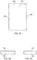
- FIG. 2shows a perspective view of a vaporizer 100 according to the present disclosure.
- FIGS. 3A, 3B and 3Cshow plan and end views of a vaporizer 100 according to the present disclosure.
- FIG. 4shows an exemplary region of contact between a vaporizer 100 and a matrix 150 .
- FIG. 5shows further exemplary regions of contact between a vaporizer 100 and a matrix 150 .
- FIG. 6shows a vaporizer 200 according to the present disclosure.
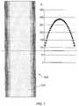
- FIG. 7shows a graphical representation of the temperature gradient formed in the vaporizer 100 .
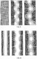
- FIG. 8shows the distribution of the electric power released across vaporizers according to the present disclosure containing no slots (left), 7 slots (middle) and 4 slots (right).
- FIG. 9shows the relative temperature distribution and gradients of the vaporizers shown in FIG. 8 .
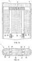
- FIG. 10shows a plan view of a device 7 incorporating a vaporizer assembly according to the present disclosure.
- FIG. 11shows a cross section view of the device 7 of FIG. 10 .
- FIG. 12shows a longitudinal cross section of a further vaporizer assembly according to the present disclosure.
- FIG. 13shows a schematic view of a further vaporizer assembly according to the present disclosure.
- FIG. 14shows a stacked configuration of vaporizer according to the present disclosure.
- FIG. 1Ashows a portion of a first vaporizer 100 according to the present disclosure.
- the vaporizer 100has a first surface 101 and a second surface 102 .
- the first and second surfacesform a common edge 110 .
- FIG. 1Aalso shows a further surface 103 which forms an independent common edge 111 with the first surface 101 and also forms a common edge 112 with the second surface 102 .
- the surface area of the first surface 101is greater than that of the second surface 102 .
- the vaporizer 100itself may be formed from a material 106 having a capillary structure 107 .
- the capillary structure 107serves to distribute the liquid to be vaporized through the vaporizer 100 .
- the capillary structure 107may extend through the entire vaporizer 100 .
- it is possible that capillary structure 107may be localized to specific areas of the vaporizer 100 .
- FIG. 2shows vaporizer 100 and in this instance vaporizer 100 has a rectangular profile. It will be appreciated that the vaporizer 100 shown in FIG. 2 has four surfaces which each form independent common edges with the first surface 101 . In this regard, second surface 102 and fourth and fifth surfaces 104 , 105 are depicted in FIGS. 3A, 3B and 3C .
- FIG. 4The interaction between the vaporizer 100 and the matrix 150 is shown in FIG. 4 .
- the matrix 150is in contact with the vaporizer via second surface 102 . More precisely, second surface 102 of vaporizer 100 contacts surface 151 of matrix 150 .
- the matrix 150may be in contact with more than one surface of the vaporizer 100 .
- Such an arrangementis depicted in FIG. 5 , where matrix 150 has a surface 151 in contact with the vaporizer 100 via second surface 102 as well as surface 153 in contact with the vaporizer 100 via third surface 103 .
- FIG. 6shows a further vaporizer 200 which has a first surface 201 , and multiple further surfaces 202 , 203 , 204 , 205 , 206 each of which independently form a common edge 210 , 211 , 213 , 214 , 215 with the first surface 201 .
- any of the multiple further surfaces shown in FIG. 6can be considered to be the second surface. Consequently, one or more matrixes may be in contact with the vaporizer via any one of the surfaces 202 , 203 , 204 , 205 , 206 .
- a single matrixmay be in contact with more than one of said surfaces and/or more than one matrix may be present and each may be in contact with one or more of said surfaces.
- the surfaces opposite to and parallel with surface 203may also be in contact with a matrix.
- the matrixneed not contact the entire second surface of the vaporizer assembly. However, this may be advantageous in order to establish a great degree of contact (and potentially flow of liquid) between the matrix and the vaporizer.
- the one or more matrixescontacts the vaporizer(s) along a “side” face, i.e. one or more of the surfaces forming a common edge with the first surface.
- This contact faceis referred to as a “side” face owing to the configuration that results from the first surface having a surface area greater than that of the second surface.
- Such a configurationmay be particularly advantageous as when the vaporizer is operational the liquid drawn from the matrix can be distributed substantially along the entire length of the vaporizer without compromising the evaporating efficiency of the vaporizer.
- the first surfacecan be left free of contact so that any liquid vaporized by the vaporizer can exit the vaporizer freely.
- Thisis typically advantageous where the vaporizer 100 , 200 assembly is incorporated into devices, such as e-cigarettes, where the flow of air through the device will pass over the first surface 101 , 201 of the vaporizer 100 , 200 and thus the vapor produced by the vaporizer 100 , 201 is able to form an aerosol more effectively.
- the specific orientation of the vaporizer and the matrix of the present assemblyis also advantageous in that it provides for a graduated vaporization profile across the vaporizer. Due to liquid being delivered to the vaporizer via the “side” face of the vaporizer, a vaporization or temperature gradient is established across the width of the vaporizer 100 , 200 . Without being bound by theory, this gradient is formed at least in part because of the greater proximity of the second (side) surface of the vaporizer to the matrix compared to the centre of the vaporizer. The relative flow of liquid through this portion of the vaporizer is therefore greater than towards the centre of the vaporizer and therefore the temperature of the vaporizer in these areas is depressed to a greater extent.
- the unheated and usually more voluminous matrixforms a heat sink for the heated vaporizer.
- This vaporization gradientis particularly advantageous if the liquid to be vaporized contains multiple substances having different boiling points.
- the natural action of the capillary structure formed in the vaporizer 100 , 200will draw the liquid inwards from the matrix 150 via the side face (second surface as defined herein) and as a result of the vaporization gradient the vaporizer simultaneously evaporates multiple substances having different boiling points.
- the liquid to be vaporizedcontains nicotine, water and glycerol, each of which has a different boiling point
- each substancecan be vaporized substantially simultaneously leading to an aerosol with a more balanced profile.
- An example of the gradient established across the vaporizer 101is shown in FIG. 7 . It will be appreciated that this gradient is generally established when the vaporizer is configured to be fed with a vaporizable liquid in a direction substantially perpendicular to the longitudinal axis of the vaporizer.
- the vaporizer of the present disclosuremay include one or more slots extending from the second surface of the vaporizer into the first surface. Vaporizers having such slots are shown in FIGS. 8 and 9 , alongside a vaporizer having no such slots. As can be seen from FIGS. 8 and 9 , the electrical power (power distribution) is influenced by the presence of the slots. When no slots are present, the electrical power generated and energy released across the device/vaporizer surface 101 is substantially constant Such a uniform generation of power/release of energy does not, however, lead to a constant temperature profile across the vaporizer as a result of the orientation of the vaporizer and matrixes, as explained above and shown in FIG. 7 . The temperature gradient induced in the vaporizer is shown again in FIG. 9 .
- slotshelps keeping the generation of power/release of energy away from the second surface, where the energy would otherwise (no slots) be immediately absorbed by the matrix which—as explained above—can be considered as a heat sink. As a result the slots are increasing the evaporation efficiency.
- the vaporizer assemblymay contain more than one matrix.
- FIG. 10depicts a device 7 , such as an e-cigarette, comprising a vaporizer assembly comprising first and second vaporizers 2 A, 2 B, each vaporizer being in contact with a respective matrix 3 a , 3 b , 3 c via multiple surfaces of the vaporizer, each surface forming an independent edge with the respective first surface of each vaporizer.
- matrix 2 Ais in contact with vaporizer 3 a via a second surface of the vaporizer 2 A, the second surface forming a common edge with the first surface of the vaporizer 2 A.
- matrix 3 bis also in contact with vaporizer 2 A via a further surface, the further surface forming an independent common edge with the first surface of the vaporizer 2 A. Additionally, matrix 3 b is in contact with vaporizer 2 B via a second surface of the vaporizer 2 B, the second surface forming a common edge with the first surface of the vaporizer 2 B. Further, vaporizer 2 B is also in contact with matrix 3 c via a further surface, the further surface forming an independent common edge with the first surface of the vaporizer 2 B. In this way, multiple vaporizers can cooperate with multiple matrixes in the vaporizer assembly so as to provide mutual support and efficient supply of liquid to the vaporizers.
- the vaporizers 100 , 2 A, 2 B, 200may include portions at the distal and proximal ends which are adapted to provide electrical contacts. These portions of the vaporizers are depicted in FIG. 10 as U+ and U ⁇ . Furthermore, in some embodiments, a bridge 6 is present which provides electrical communication between multiple vaporizers so as to simply any electrical connections that may be required.
- FIG. 11shows a cross-sectional profile of device 7 (transverse to the longitudinal dimension of the device).
- device 7includes vaporizers 2 A and 2 B, matrixes 3 a , 3 b , 3 c , and channels 4 ′, 4 ′′ formed above and below vaporizer 2 A and channels 5 ′, 5 ′′ formed above and below vaporizer 2 B.
- Said channelsare formed by the upper and lower major surfaces of the vaporizers, the side surfaces of the matrixes 3 a , 3 b , and 3 c , as well as the inner walls of housing 1 .
- such an arrangementallows the vaporizers to cooperate with multiple matrixes in the vaporizer assembly so as to provide mutual support, efficient supply of liquid to the vaporizers and also the ability to form vaporization gradients across each vaporizer whilst at the same time ensuring that the first surfaces (upper surfaces as depicted in FIG. 11 ) remain substantially or completely contact free. This ensures efficient provision of vapor to any air channel formed above the vaporizers. Of course, the same applies to the surfaces (lower surfaces as depicted in FIG. 11 ).
- the device 7encloses the vaporizers and matrixes by a device wall 1 .
- the device wall 1also referred to as a housing, may encompasses/defines other features/components typically found in e-cigarettes: a mouthpiece; an air inlet and air outlet interconnected by channels 4 ′, 4 ′′, 5 ′, 5 ′′; a battery; a PCB, various sensors and microprocessors used to operate the device in response to use of the device (e.g. inhalation though the mouthpiece); and one or more LEDs.
- the device 7 depicted in FIG. 11is not intended to be limiting and any combination of vaporizers and matrixes as described herein can be incorporated into a suitable device.
- Device 7is generally operated as follows. A user places the mouthpiece of the device to his/her mouth and inhales, thereby causing air to flow through the device. Said air flow (or reduced pressure) is detected by the sensor in the device, which then relays information to the microprocessor that the device is in use. Power is then delivered to the vaporizer and, owing to the electrical resistance of the vaporizer, the temperature of the vaporizer increases. Due to the capillary effect induced by the capillary structures of the vaporizer and matrix and due to the contact between the vaporizer and the matrix (which contains a liquid to be vaporized) liquid is drawn by capillary force from the matrix to the vaporizer.
- each vaporizer 2 A and 2 Bwill display a greater temperature at its center compared to the temperature at the surface in contact with the respective matrixes 3 a , 3 b and 3 c .
- vaporis expelled from the vaporizers 2 A and 2 B into the channels 4 ′, 4 ′′, 5 ′ and 5 ′′. Air flowing through the device 7 also travels through channels 4 ′, 4 ′′, 5 ′ and 5 ′′ and as a result mixes with the expelled vapor. The vapor cools and condenses to form an aerosol which travels through the device 7 to the mouthpiece and is inhaled by the user. As vapor is expelled from the vaporizers 2 A and 2 B, further liquid is drawn from the matrixes 3 a , 3 b and 3 c and the volume of liquid present inside the vaporizer is replenished.
- the sensor within the devicedetects the relative change in flow (or pressure) and communicates this to the microprocessor, following which the power to the vaporizer is terminated, the temperature of the vaporizer drops and liquid ceases to be vaporized (at least to the same extent as during operation).
- the power to the vaporizermay be terminated after a certain period of time (e.g. 2 seconds after start of inhalation) has elapsed.
- the microprocessormay also cause other functions to be activated, such as operation of one or more LEDs etc.
- FIG. 12A further embodiment of a vaporizer assembly according to the present disclosure is shown in FIG. 12 .
- the vaporizer assembly depicted in FIG. 12comprises a matrix 250 which is tubular and a matrix 100 which is dimensioned as shown in FIG. 2 .
- vaporizer 100has a first surface 101 and second surfaces 102 and 104 .
- Second surfaces 102 and 104are in contact with surfaces 251 and 252 of matrix 250 .
- the orientation of vaporizer 100 within tubular matrix 250is such that air channels 300 are formed above and below the vaporizer 100 .
- Matrix 250may be made of a resilient material. Further, the inner diameter of matrix 250 may be slightly smaller than the width of vaporizer 100 so that vaporizer 100 is supported by matrix 250 (via, for example, friction fit/the resilient nature of matrix 250 ).
- FIG. 13shows a schematic view of a further device 1300 including a vaporizer assembly 1302 according to the present disclosure.
- the embodiment shown in FIG. 13includes a power source 1306 , one or more sensors 1310 ; and optionally one or more LEDs 1308 , a first part and second part of a housing ( 1312 and 1314 , respectively), a mouthpiece 1316 , and a connector 1318 for establishing mechanical and electrical connection according to the present disclosure.
- the housing 1304may be separable into two or more parts.
- the vaporizer assembly 1302 and mouthpiece 1316may be contained in the first part 1312 while the power source 1306 , LED 1308 , and one or more sensors 1310 may be contained in the second part 1314 .
- Each of the parts ( 1312 , 1314 ) of the housing 1304may contain a suitable aperture (not shown) to allow air flow through the device 1300 and out of the mouthpiece 1316 .
- the device 1300may be configured such that only one of the parts of the housing, e.g. the first part 1312 , has suitable apertures.
- the housingmay be separable into three parts and in this case, the vaporizer assembly may be contained in two different parts of the housing that can be brought together to form the vaporizer assembly.
- the vaporizer assembly 1302is part of a first housing part 1312 and said housing part 1312 includes a mouthpiece 1316 and a connector 1318 for establishing mechanical and electrical connection with a further housing part 1314 .
- the first housingmay form a cartomizer comprising the vaporizer assembly according to the present disclosure.
- each vaporizermay be in a stacked configuration (above and below each other/in different planes), or in alternative embodiments they could be oriented in substantially the same plane.
- each vaporizermay be separated by one or more matrixes (e.g. vertically or horizontally sandwiched), in embodiments.
- the interaction between the vaporizers 1400 A- 1400 C and the matrix 1450is also shown in FIG. 14 , and is substantially similar to the arrangement described above with respect to FIG. 4 .
- the matrix 1450is in contact with the vaporizers ( 1400 A- 1400 C) via second surfaces thereof, such as second surface 1402 corresponding to vaporizer 1401 A.
- the second surfaces of the vaporizer 1400 A- 1400 Ceach contact the surface 1451 of matrix 1450 .
Landscapes
- Health & Medical Sciences (AREA)
- Engineering & Computer Science (AREA)
- Hematology (AREA)
- Life Sciences & Earth Sciences (AREA)
- Chemical Kinetics & Catalysis (AREA)
- Bioinformatics & Cheminformatics (AREA)
- Pulmonology (AREA)
- Anesthesiology (AREA)
- Biomedical Technology (AREA)
- Heart & Thoracic Surgery (AREA)
- Chemical & Material Sciences (AREA)
- General Chemical & Material Sciences (AREA)
- Animal Behavior & Ethology (AREA)
- General Health & Medical Sciences (AREA)
- Public Health (AREA)
- Veterinary Medicine (AREA)
- Catching Or Destruction (AREA)
- Chemical Vapour Deposition (AREA)
- Vaporization, Distillation, Condensation, Sublimation, And Cold Traps (AREA)
- Filling Or Discharging Of Gas Storage Vessels (AREA)
- Cooling Or The Like Of Semiconductors Or Solid State Devices (AREA)
Abstract
Description
Claims (24)
Applications Claiming Priority (3)
| Application Number | Priority Date | Filing Date | Title |
|---|---|---|---|
| GBGB1411483.9AGB201411483D0 (en) | 2014-06-27 | 2014-06-27 | Vaporizer Assembly |
| GB1411483.9 | 2014-06-27 | ||
| PCT/GB2015/051845WO2015198049A1 (en) | 2014-06-27 | 2015-06-25 | Vaporizer assembly |
Related Parent Applications (1)
| Application Number | Title | Priority Date | Filing Date |
|---|---|---|---|
| PCT/GB2015/051845A-371-Of-InternationalWO2015198049A1 (en) | 2014-06-27 | 2015-06-25 | Vaporizer assembly |
Related Child Applications (1)
| Application Number | Title | Priority Date | Filing Date |
|---|---|---|---|
| US16/871,279ContinuationUS11058152B2 (en) | 2014-06-27 | 2020-05-11 | Vaporizer assembly having a vaporizer and a matrix |
Publications (2)
| Publication Number | Publication Date |
|---|---|
| US20170127725A1 US20170127725A1 (en) | 2017-05-11 |
| US10687555B2true US10687555B2 (en) | 2020-06-23 |
Family
ID=51410254
Family Applications (2)
| Application Number | Title | Priority Date | Filing Date |
|---|---|---|---|
| US15/322,221ActiveUS10687555B2 (en) | 2014-06-27 | 2015-06-25 | Vaporizer assembly having a vaporizer and a matrix |
| US16/871,279ActiveUS11058152B2 (en) | 2014-06-27 | 2020-05-11 | Vaporizer assembly having a vaporizer and a matrix |
Family Applications After (1)
| Application Number | Title | Priority Date | Filing Date |
|---|---|---|---|
| US16/871,279ActiveUS11058152B2 (en) | 2014-06-27 | 2020-05-11 | Vaporizer assembly having a vaporizer and a matrix |
Country Status (15)
| Country | Link |
|---|---|
| US (2) | US10687555B2 (en) |
| EP (1) | EP3160272B1 (en) |
| JP (2) | JP6531119B2 (en) |
| KR (2) | KR102120211B1 (en) |
| CN (2) | CN111789298A (en) |
| AU (1) | AU2015278890B2 (en) |
| CA (1) | CA2951511C (en) |
| ES (1) | ES2753593T3 (en) |
| GB (1) | GB201411483D0 (en) |
| MY (1) | MY181844A (en) |
| PH (1) | PH12016502549B1 (en) |
| PL (1) | PL3160272T3 (en) |
| RU (2) | RU2656952C1 (en) |
| UA (1) | UA120852C2 (en) |
| WO (1) | WO2015198049A1 (en) |
Families Citing this family (44)
| Publication number | Priority date | Publication date | Assignee | Title |
|---|---|---|---|---|
| US20160345631A1 (en) | 2005-07-19 | 2016-12-01 | James Monsees | Portable devices for generating an inhalable vapor |
| CN103491815B (en) | 2011-02-11 | 2016-01-20 | 巴特马克有限公司 | Inhalator assembly |
| US10279934B2 (en) | 2013-03-15 | 2019-05-07 | Juul Labs, Inc. | Fillable vaporizer cartridge and method of filling |
| US10159282B2 (en) | 2013-12-23 | 2018-12-25 | Juul Labs, Inc. | Cartridge for use with a vaporizer device |
| USD842536S1 (en) | 2016-07-28 | 2019-03-05 | Juul Labs, Inc. | Vaporizer cartridge |
| US10076139B2 (en) | 2013-12-23 | 2018-09-18 | Juul Labs, Inc. | Vaporizer apparatus |
| DE202014011260U1 (en) | 2013-12-23 | 2018-11-13 | Juul Labs Uk Holdco Limited | Systems for an evaporation device |
| USD825102S1 (en) | 2016-07-28 | 2018-08-07 | Juul Labs, Inc. | Vaporizer device with cartridge |
| US20160366947A1 (en) | 2013-12-23 | 2016-12-22 | James Monsees | Vaporizer apparatus |
| US10058129B2 (en) | 2013-12-23 | 2018-08-28 | Juul Labs, Inc. | Vaporization device systems and methods |
| MX394125B (en) | 2014-12-05 | 2025-03-24 | Juul Labs Inc | CALIBRATED DOSE CONTROL |
| DE102015009276A1 (en)* | 2015-07-16 | 2017-01-19 | Torsten Niemeitz | Unit for volatilizing nicotine, flavors and therapeutically useful substances in a vaporizer |
| GB2542838B (en) | 2015-10-01 | 2022-01-12 | Nicoventures Trading Ltd | Aerosol provision system |
| CO2018009342A2 (en) | 2016-02-11 | 2018-09-20 | Juul Labs Inc | Secure fixing cartridges for vaporizing devices |
| EP3413960B1 (en) | 2016-02-11 | 2021-03-31 | Juul Labs, Inc. | Fillable vaporizer cartridge and method of filling |
| US10405582B2 (en) | 2016-03-10 | 2019-09-10 | Pax Labs, Inc. | Vaporization device with lip sensing |
| WO2017185051A1 (en) | 2016-04-22 | 2017-10-26 | Pax Labs, Inc. | Aerosol devices having compartmentalized materials |
| ES2987583T3 (en) | 2016-04-27 | 2024-11-15 | Nicoventures Trading Ltd | Electronic aerosol supply system and aerosol vaporizer |
| USD849996S1 (en) | 2016-06-16 | 2019-05-28 | Pax Labs, Inc. | Vaporizer cartridge |
| USD836541S1 (en) | 2016-06-23 | 2018-12-25 | Pax Labs, Inc. | Charging device |
| USD851830S1 (en) | 2016-06-23 | 2019-06-18 | Pax Labs, Inc. | Combined vaporizer tamp and pick tool |
| GB201707050D0 (en) | 2017-05-03 | 2017-06-14 | British American Tobacco Investments Ltd | Data communication |
| CN106974324A (en)* | 2017-05-19 | 2017-07-25 | 深圳市新宜康科技有限公司 | Electronic cigarette atomizing cored structure and electronic smoke atomizer by heat generating components of metal felt |
| EP3675661B1 (en) | 2017-08-28 | 2023-06-07 | Juul Labs, Inc. | Wick for vaporizer device |
| USD887632S1 (en) | 2017-09-14 | 2020-06-16 | Pax Labs, Inc. | Vaporizer cartridge |
| GB201722241D0 (en) | 2017-12-29 | 2018-02-14 | British American Tobacco Investments Ltd | Data capture across devices |
| GB201722278D0 (en) | 2017-12-29 | 2018-02-14 | British American Tobacco Investments Ltd | Device identification and method |
| GB201801146D0 (en) | 2018-01-24 | 2018-03-07 | Nicoventures Trading Ltd | Aerosol source for a vapour provision system |
| GB201801144D0 (en) | 2018-01-24 | 2018-03-07 | Nicoventures Trading Ltd | Aerosol source for a vapour provision system |
| GB201801143D0 (en)* | 2018-01-24 | 2018-03-07 | Nicoventures Trading Ltd | vapour provision apparatus and systems |
| GB201801145D0 (en) | 2018-01-24 | 2018-03-07 | Nicoventures Trading Ltd | Vapour provision systems |
| AT521172B1 (en)* | 2018-05-23 | 2019-11-15 | Von Erl Gmbh | Evaporator body for an evaporator device of an inhaler |
| JP7502015B2 (en) | 2018-11-08 | 2024-06-18 | ジュール・ラブズ・インコーポレイテッド | Vaporizer device with one or more heating elements |
| CN113939203A (en) | 2019-01-15 | 2022-01-14 | 尤尔实验室有限公司 | Evaporator device |
| US20230354884A1 (en)* | 2019-01-24 | 2023-11-09 | Inno-It Co., Ltd. | Aerosol Generation System |
| US12336565B2 (en)* | 2019-01-24 | 2025-06-24 | Inno-It Co., Ltd. | Liquid cartridge that can be inserted into electrically heated smoking article, electrically heated smoking article including the same, and aerosol generating device and system therefor |
| WO2020205561A1 (en) | 2019-03-29 | 2020-10-08 | Juul Labs, Inc. | Cartridges for vaporizer devices |
| CN112167725B (en)* | 2019-07-03 | 2023-03-14 | 深圳市合元科技有限公司 | Application of organic porous material in aerosol generating device and atomizer using material |
| WO2021053225A1 (en) | 2019-09-20 | 2021-03-25 | Nerudia Limited | Smoking substitute apparatus |
| EP3795003A1 (en)* | 2019-09-20 | 2021-03-24 | Nerudia Limited | Smoking substitute apparatus |
| GB2586301B (en) | 2020-04-07 | 2021-08-25 | Splash Tm Gmbh | Stable-Foam inhalation Device and Cartridge |
| KR20230124632A (en)* | 2020-12-22 | 2023-08-25 | 필립모리스 프로덕츠 에스.에이. | Cartridges for use in aerosol-generating systems |
| DE102021127532B4 (en) | 2021-10-22 | 2023-11-09 | Körber Technologies Gmbh | Vaporizer device, vaporizer tank unit, inhaler and method of making a vaporizer device |
| WO2024243722A1 (en)* | 2023-05-26 | 2024-12-05 | Imperial Tobacco Limited | Heating system |
Citations (85)
| Publication number | Priority date | Publication date | Assignee | Title |
|---|---|---|---|---|
| US4223292A (en) | 1977-07-25 | 1980-09-16 | Hitachi, Ltd. | Hall element |
| US4588976A (en) | 1984-11-19 | 1986-05-13 | Microelettrica Scientifica S.P.S. | Resistors obtained from sheet material |
| US4735217A (en) | 1986-08-21 | 1988-04-05 | The Procter & Gamble Company | Dosing device to provide vaporized medicament to the lungs as a fine aerosol |
| US4922901A (en) | 1988-09-08 | 1990-05-08 | R. J. Reynolds Tobacco Company | Drug delivery articles utilizing electrical energy |
| US5060671A (en) | 1989-12-01 | 1991-10-29 | Philip Morris Incorporated | Flavor generating article |
| US5095921A (en) | 1990-11-19 | 1992-03-17 | Philip Morris Incorporated | Flavor generating article |
| US5179966A (en) | 1990-11-19 | 1993-01-19 | Philip Morris Incorporated | Flavor generating article |
| US5222362A (en) | 1989-01-10 | 1993-06-29 | Maus Daryl D | Heat-activated drug delivery system and thermal actuators therefor |
| US5322075A (en) | 1992-09-10 | 1994-06-21 | Philip Morris Incorporated | Heater for an electric flavor-generating article |
| US5530225A (en) | 1991-03-11 | 1996-06-25 | Philip Morris Incorporated | Interdigitated cylindrical heater for use in an electrical smoking article |
| US5613505A (en) | 1992-09-11 | 1997-03-25 | Philip Morris Incorporated | Inductive heating systems for smoking articles |
| US5666978A (en) | 1992-09-11 | 1997-09-16 | Philip Morris Incorporated | Electrical smoking system for delivering flavors and method for making same |
| US5692525A (en) | 1992-09-11 | 1997-12-02 | Philip Morris Incorporated | Cigarette for electrical smoking system |
| US5771845A (en) | 1994-05-18 | 1998-06-30 | Gaz De France | Vaporization method device |
| JPH1189551A (en) | 1997-07-23 | 1999-04-06 | Japan Tobacco Inc | Flavor or perfume generator |
| US6124579A (en) | 1997-10-06 | 2000-09-26 | Watlow Electric Manufacturing | Molded polymer composite heater |
| US6155268A (en) | 1997-07-23 | 2000-12-05 | Japan Tobacco Inc. | Flavor-generating device |
| WO2001067819A1 (en) | 2000-03-03 | 2001-09-13 | Cooper Richard P | Thin film tubular heater |
| US20020113685A1 (en) | 2000-07-21 | 2002-08-22 | Masatoshi Izaki | Thermal fuse, battery pack, and method of manufacturing thermal fuse |
| US20030049025A1 (en) | 2000-01-13 | 2003-03-13 | Hermann Neumann | Chip that comprises an active agent and an integrated heating element |
| WO2003037412A2 (en) | 2001-10-31 | 2003-05-08 | Gw Pharma Limited | A device, method and resistive element for vaporising a medicament |
| US6598607B2 (en)* | 2001-10-24 | 2003-07-29 | Brown & Williamson Tobacco Corporation | Non-combustible smoking device and fuel element |
| US20030186474A1 (en) | 2001-10-31 | 2003-10-02 | Haluzak Charles C. | Drop generator for ultra-small droplets |
| WO2003103387A2 (en) | 2002-06-06 | 2003-12-18 | S.C. Johnson & Son, Inc. | Localized surface volatilization |
| US6671450B2 (en) | 2000-09-01 | 2003-12-30 | Lightwave Microsystems Corporation | Apparatus and method to metallize, reinforce, and hermetically seal multiple optical fibers |
| US20040096204A1 (en) | 2002-11-15 | 2004-05-20 | Engineered Glass Products, Llc. | Vacuum insulated quartz tube heater assembly |
| US20050211711A1 (en) | 2004-03-23 | 2005-09-29 | Reid Aarne H | Vacuum insulated structures |
| US20050268911A1 (en) | 2004-06-03 | 2005-12-08 | Alexza Molecular Delivery Corporation | Multiple dose condensation aerosol devices and methods of forming condensation aerosols |
| US20070047434A1 (en) | 2003-08-22 | 2007-03-01 | Bernd Stilling | Method for starting lasers in a network |
| US20070155255A1 (en) | 2005-12-29 | 2007-07-05 | Charles Galauner | Heating element connector assembly with press-fit terminals |
| US20080047956A1 (en)* | 2006-08-28 | 2008-02-28 | Richard Dudman | Inductively heated warming system |
| US20080216828A1 (en) | 2007-03-09 | 2008-09-11 | Alexza Pharmaceuticals, Inc. | Heating unit for use in a drug delivery device |
| US20090126745A1 (en) | 2006-05-16 | 2009-05-21 | Lik Hon | Emulation Aerosol Sucker |
| EP1736065B1 (en) | 2004-04-14 | 2009-06-03 | Best Partners Worldwide Limited | An aerosol electronic cigarette |
| US20090220222A1 (en)* | 2005-05-16 | 2009-09-03 | Vapore, Inc. | Capillary force vaporizers |
| WO2009118085A1 (en) | 2008-03-25 | 2009-10-01 | Philip Morris Products S.A. | Method for controlling the formation of smoke constituents in an electrical aerosol generating system |
| US20090272379A1 (en) | 2008-04-30 | 2009-11-05 | Philip Morris Usa Inc. | Electrically heated smoking system having a liquid storage portion |
| CN201375023Y (en) | 2009-04-15 | 2010-01-06 | 中国科学院理化技术研究所 | A heating and atomizing electronic cigarette powered by a capacitor |
| WO2010045671A1 (en) | 2008-10-23 | 2010-04-29 | Helmut Buchberger | Inhaler |
| CN201767029U (en) | 2010-08-13 | 2011-03-23 | 李永海 | Disposable atomizer of electronic cigarette |
| US20110094523A1 (en) | 2009-10-27 | 2011-04-28 | Philip Morris Usa Inc. | Smoking system having a liquid storage portion |
| EP2316286A1 (en) | 2009-10-29 | 2011-05-04 | Philip Morris Products S.A. | An electrically heated smoking system with improved heater |
| CN201830900U (en) | 2010-06-09 | 2011-05-18 | 李永海 | Tobacco juice atomization device for electronic cigarette |
| US20110155153A1 (en) | 2009-12-30 | 2011-06-30 | Philip Morris Usa Inc. | Heater for an electrically heated aerosol generating system |
| EP2340730A1 (en) | 2009-12-30 | 2011-07-06 | Philip Morris Products S.A. | A shaped heater for an aerosol generating system |
| WO2011109849A1 (en) | 2010-03-10 | 2011-09-15 | Helmut Buchberger | Planar evaporator |
| EP2399636A1 (en) | 2010-06-23 | 2011-12-28 | Philip Morris Products S.A. | An improved aerosol generator and liquid storage portion for use with the aerosol generator |
| EP2460424A1 (en) | 2010-12-03 | 2012-06-06 | Philip Morris Products S.A. | An aerosol generating system with leakage prevention |
| DE202012005406U1 (en) | 2012-05-31 | 2012-06-25 | Thomas Brückmann | Cigarette-type, electrically operated inhaler with a mouthpiece, evaporator and tank space |
| CN202354377U (en) | 2011-11-24 | 2012-08-01 | 深圳市奉天元电子有限公司 | Electronic cigarette atomizer and electronic cigarette |
| WO2012106739A1 (en) | 2011-02-11 | 2012-08-16 | Helmut Buchberger | Inhaler component |
| US20130056012A1 (en) | 2010-03-03 | 2013-03-07 | Alex Hearn | Simulated cigarette |
| EP2574247A1 (en) | 2011-09-28 | 2013-04-03 | Philip Morris Products S.A. | Permeable electric heat resistant foil for evaporating liquids out of disposable mouthpieces with evaporator nozzles |
| WO2013057185A1 (en) | 2011-10-21 | 2013-04-25 | Batmark Limited | Inhaler component |
| WO2013060781A1 (en) | 2011-10-27 | 2013-05-02 | Philip Morris Products S.A. | Aerosol generating system with improved aerosol production |
| WO2013068304A1 (en) | 2011-11-07 | 2013-05-16 | Philip Morris Products S.A. | Smoking article with liquid delivery material |
| WO2013083635A1 (en) | 2011-12-07 | 2013-06-13 | Philip Morris Products S.A. | An aerosol generating device having airflow inlets |
| WO2013083634A1 (en) | 2011-12-08 | 2013-06-13 | Philip Morris Products S.A. | An aerosol generating device with a capillary interface |
| WO2013083636A1 (en) | 2011-12-08 | 2013-06-13 | Philip Morris Products S.A. | An aerosol generating device with adjustable airflow |
| US20130152922A1 (en) | 2011-12-14 | 2013-06-20 | Atmos Technology, Llc. | Portable Pen Sized Electric Herb Vaporizer with Ceramic Heating Chamber |
| WO2013098395A1 (en) | 2011-12-30 | 2013-07-04 | Philip Morris Products S.A. | Aerosol generating device with improved temperature distribution |
| WO2013098409A1 (en) | 2011-12-30 | 2013-07-04 | Philip Morris Products S.A. | Smoking article with front-plug and aerosol-forming substrate and method |
| WO2013098410A2 (en) | 2011-12-30 | 2013-07-04 | Philip Morris Products S.A. | Smoking article with front-plug and method |
| WO2013102609A2 (en) | 2012-01-03 | 2013-07-11 | Philip Morris Products S.A. | An aerosol generating device and system with improved airflow |
| US20130192615A1 (en)* | 2012-01-31 | 2013-08-01 | Altria Client Services Inc. | Electronic cigarette |
| US20130213419A1 (en)* | 2012-02-22 | 2013-08-22 | Altria Client Services Inc. | Electronic smoking article and improved heater element |
| WO2013160112A2 (en) | 2012-04-23 | 2013-10-31 | British American Tobacco (Investments) Limited | Heating smokeable material |
| US20140000638A1 (en) | 2012-06-28 | 2014-01-02 | R.J. Reynolds Tobacco Company | Reservoir and heater system for controllable delivery of multiple aerosolizable materials in an electronic smoking article |
| WO2014037794A2 (en) | 2012-09-04 | 2014-03-13 | R. J. Reynolds Tobacco Company | Electronic smoking article comprising one or more microheaters |
| US20140182608A1 (en) | 2011-09-06 | 2014-07-03 | British American Tobacco (Investments) Limited | Heating smokable material |
| US20140196734A1 (en)* | 2013-01-16 | 2014-07-17 | Qiuming Liu | Electronic Cigarette Tightly Engaged By Expansion |
| WO2014130772A1 (en) | 2013-02-22 | 2014-08-28 | Altria Client Services Inc. | Electronic smoking article |
| US20140238422A1 (en)* | 2013-02-22 | 2014-08-28 | Altria Client Services Inc. | Electronic smoking article |
| US20150007835A1 (en)* | 2013-07-05 | 2015-01-08 | Qiuming Liu | Electronic cigarette |
| US20150030317A1 (en) | 2012-03-15 | 2015-01-29 | Resmed Limited | Heating apparatus |
| US20150059780A1 (en)* | 2013-08-28 | 2015-03-05 | R.J. Reynolds Tobacco Company | Carbon conductive substrate for electronic smoking article |
| US20150157055A1 (en)* | 2012-07-16 | 2015-06-11 | Nicoventures Holdings Limited | Electronic vapour provision device |
| US20150208728A1 (en) | 2012-07-16 | 2015-07-30 | Nicoventures Holdings Limited | Electronic vapour provision device |
| US20150216237A1 (en)* | 2014-01-22 | 2015-08-06 | E-Nicotine Technology, Inc. | Methods and devices for smoking urge relief |
| US20160353802A1 (en)* | 2014-02-10 | 2016-12-08 | Philip Morris Products S.A. | Cartridge for an aerosol-generating system |
| US20170027234A1 (en)* | 2014-04-30 | 2017-02-02 | Philip Morris Products S.A. | Aerosol generating device with battery indication |
| US20170027225A1 (en) | 2014-01-29 | 2017-02-02 | Batmark Limited | Aerosol-forming member |
| US9572373B2 (en)* | 2013-09-29 | 2017-02-21 | Shenzhen Smoore Technology Limited | Electronic cigarette |
| US20170188629A1 (en)* | 2014-01-29 | 2017-07-06 | Batmark Limited | Aerosol-forming member |
| US20170188630A1 (en) | 2014-01-29 | 2017-07-06 | Batmark Limited | Aerosol-forming member |
Family Cites Families (6)
| Publication number | Priority date | Publication date | Assignee | Title |
|---|---|---|---|---|
| CN1045691C (en)* | 1990-04-21 | 1999-10-13 | 穆秀珍 | Process for protecting electrolyte of accumulator |
| US7431570B2 (en)* | 2002-02-19 | 2008-10-07 | Vapore, Inc. | Capillary pumps for vaporization of liquids |
| JP5901892B2 (en)* | 2011-05-24 | 2016-04-13 | シャープ株式会社 | Fuel cell |
| WO2013017441A1 (en)* | 2011-08-01 | 2013-02-07 | Fmp Technology Gmbh Fluid Measurements & Projects | Method and device for drying a fluid film applied to a substrate |
| CN203168034U (en)* | 2013-01-05 | 2013-09-04 | 刘秋明 | Electronic cigarette device, electronic cigarette and atomizing device of electronic cigarette |
| DE102013106520B4 (en)* | 2013-06-21 | 2024-02-08 | Röhm Gmbh | Drilling device |
- 2014
- 2014-06-27GBGBGB1411483.9Apatent/GB201411483D0/ennot_activeCeased
- 2015
- 2015-06-25CACA2951511Apatent/CA2951511C/enactiveActive
- 2015-06-25KRKR1020197025252Apatent/KR102120211B1/enactiveActive
- 2015-06-25USUS15/322,221patent/US10687555B2/enactiveActive
- 2015-06-25EPEP15732918.6Apatent/EP3160272B1/enactiveActive
- 2015-06-25MYMYPI2016704639Apatent/MY181844A/enunknown
- 2015-06-25RURU2016151783Apatent/RU2656952C1/enactive
- 2015-06-25CNCN202010711257.3Apatent/CN111789298A/enactivePending
- 2015-06-25KRKR1020167036321Apatent/KR102017873B1/enactiveActive
- 2015-06-25ESES15732918Tpatent/ES2753593T3/enactiveActive
- 2015-06-25WOPCT/GB2015/051845patent/WO2015198049A1/enactiveApplication Filing
- 2015-06-25JPJP2016575451Apatent/JP6531119B2/enactiveActive
- 2015-06-25UAUAA201612948Apatent/UA120852C2/enunknown
- 2015-06-25RURU2018119467Apatent/RU2673616C2/enactive
- 2015-06-25PLPL15732918Tpatent/PL3160272T3/enunknown
- 2015-06-25CNCN201580034426.1Apatent/CN106455727B/ennot_activeExpired - Fee Related
- 2015-06-25AUAU2015278890Apatent/AU2015278890B2/ennot_activeCeased
- 2016
- 2016-12-20PHPH12016502549Apatent/PH12016502549B1/enunknown
- 2019
- 2019-05-20JPJP2019094523Apatent/JP6864035B2/enactiveActive
- 2020
- 2020-05-11USUS16/871,279patent/US11058152B2/enactiveActive
Patent Citations (111)
| Publication number | Priority date | Publication date | Assignee | Title |
|---|---|---|---|---|
| US4223292A (en) | 1977-07-25 | 1980-09-16 | Hitachi, Ltd. | Hall element |
| US4588976A (en) | 1984-11-19 | 1986-05-13 | Microelettrica Scientifica S.P.S. | Resistors obtained from sheet material |
| US4735217A (en) | 1986-08-21 | 1988-04-05 | The Procter & Gamble Company | Dosing device to provide vaporized medicament to the lungs as a fine aerosol |
| US4922901A (en) | 1988-09-08 | 1990-05-08 | R. J. Reynolds Tobacco Company | Drug delivery articles utilizing electrical energy |
| US5222362A (en) | 1989-01-10 | 1993-06-29 | Maus Daryl D | Heat-activated drug delivery system and thermal actuators therefor |
| US5060671A (en) | 1989-12-01 | 1991-10-29 | Philip Morris Incorporated | Flavor generating article |
| US5095921A (en) | 1990-11-19 | 1992-03-17 | Philip Morris Incorporated | Flavor generating article |
| US5179966A (en) | 1990-11-19 | 1993-01-19 | Philip Morris Incorporated | Flavor generating article |
| US5530225A (en) | 1991-03-11 | 1996-06-25 | Philip Morris Incorporated | Interdigitated cylindrical heater for use in an electrical smoking article |
| US5322075A (en) | 1992-09-10 | 1994-06-21 | Philip Morris Incorporated | Heater for an electric flavor-generating article |
| US5613505A (en) | 1992-09-11 | 1997-03-25 | Philip Morris Incorporated | Inductive heating systems for smoking articles |
| US5666978A (en) | 1992-09-11 | 1997-09-16 | Philip Morris Incorporated | Electrical smoking system for delivering flavors and method for making same |
| US5692525A (en) | 1992-09-11 | 1997-12-02 | Philip Morris Incorporated | Cigarette for electrical smoking system |
| US5771845A (en) | 1994-05-18 | 1998-06-30 | Gaz De France | Vaporization method device |
| JPH1189551A (en) | 1997-07-23 | 1999-04-06 | Japan Tobacco Inc | Flavor or perfume generator |
| US6155268A (en) | 1997-07-23 | 2000-12-05 | Japan Tobacco Inc. | Flavor-generating device |
| US6124579A (en) | 1997-10-06 | 2000-09-26 | Watlow Electric Manufacturing | Molded polymer composite heater |
| US20030049025A1 (en) | 2000-01-13 | 2003-03-13 | Hermann Neumann | Chip that comprises an active agent and an integrated heating element |
| WO2001067819A1 (en) | 2000-03-03 | 2001-09-13 | Cooper Richard P | Thin film tubular heater |
| US20020113685A1 (en) | 2000-07-21 | 2002-08-22 | Masatoshi Izaki | Thermal fuse, battery pack, and method of manufacturing thermal fuse |
| US6671450B2 (en) | 2000-09-01 | 2003-12-30 | Lightwave Microsystems Corporation | Apparatus and method to metallize, reinforce, and hermetically seal multiple optical fibers |
| US6598607B2 (en)* | 2001-10-24 | 2003-07-29 | Brown & Williamson Tobacco Corporation | Non-combustible smoking device and fuel element |
| WO2003037412A2 (en) | 2001-10-31 | 2003-05-08 | Gw Pharma Limited | A device, method and resistive element for vaporising a medicament |
| US20030186474A1 (en) | 2001-10-31 | 2003-10-02 | Haluzak Charles C. | Drop generator for ultra-small droplets |
| US20050063686A1 (en) | 2001-10-31 | 2005-03-24 | Whittle Brian Anthony | Device, method and resistive element for vaporising a medicament |
| WO2003103387A2 (en) | 2002-06-06 | 2003-12-18 | S.C. Johnson & Son, Inc. | Localized surface volatilization |
| US20040096204A1 (en) | 2002-11-15 | 2004-05-20 | Engineered Glass Products, Llc. | Vacuum insulated quartz tube heater assembly |
| US20070047434A1 (en) | 2003-08-22 | 2007-03-01 | Bernd Stilling | Method for starting lasers in a network |
| US20050211711A1 (en) | 2004-03-23 | 2005-09-29 | Reid Aarne H | Vacuum insulated structures |
| US7374063B2 (en) | 2004-03-23 | 2008-05-20 | Concept Group Inc. | Vacuum insulated structures |
| US20130213420A1 (en) | 2004-04-14 | 2013-08-22 | Ruyan Investment (Holdings) Limited | Electronic atomization cigarette |
| US8393331B2 (en) | 2004-04-14 | 2013-03-12 | Ruyan Investment (Holdings) Limited | Electronic atomization cigarette |
| EP1736065B1 (en) | 2004-04-14 | 2009-06-03 | Best Partners Worldwide Limited | An aerosol electronic cigarette |
| US20050268911A1 (en) | 2004-06-03 | 2005-12-08 | Alexza Molecular Delivery Corporation | Multiple dose condensation aerosol devices and methods of forming condensation aerosols |
| US20090220222A1 (en)* | 2005-05-16 | 2009-09-03 | Vapore, Inc. | Capillary force vaporizers |
| US20070155255A1 (en) | 2005-12-29 | 2007-07-05 | Charles Galauner | Heating element connector assembly with press-fit terminals |
| US20090126745A1 (en) | 2006-05-16 | 2009-05-21 | Lik Hon | Emulation Aerosol Sucker |
| US8375957B2 (en) | 2006-05-16 | 2013-02-19 | Ruyan Investment (Holdings) Limited | Electronic cigarette |
| US8365742B2 (en) | 2006-05-16 | 2013-02-05 | Ruyan Investment (Holdings) Limited | Aerosol electronic cigarette |
| JP2009537120A (en) | 2006-05-16 | 2009-10-29 | ホン、リック | Emulation aerosol inhaler |
| US8156944B2 (en) | 2006-05-16 | 2012-04-17 | Ruyan Investments (Holdings) Limited | Aerosol electronic cigarette |
| US20080047956A1 (en)* | 2006-08-28 | 2008-02-28 | Richard Dudman | Inductively heated warming system |
| US20080216828A1 (en) | 2007-03-09 | 2008-09-11 | Alexza Pharmaceuticals, Inc. | Heating unit for use in a drug delivery device |
| EP2110033A1 (en) | 2008-03-25 | 2009-10-21 | Philip Morris Products S.A. | Method for controlling the formation of smoke constituents in an electrical aerosol generating system |
| WO2009118085A1 (en) | 2008-03-25 | 2009-10-01 | Philip Morris Products S.A. | Method for controlling the formation of smoke constituents in an electrical aerosol generating system |
| US20090272379A1 (en) | 2008-04-30 | 2009-11-05 | Philip Morris Usa Inc. | Electrically heated smoking system having a liquid storage portion |
| US20110226236A1 (en)* | 2008-10-23 | 2011-09-22 | Helmut Buchberger | Inhaler |
| US20140299125A1 (en) | 2008-10-23 | 2014-10-09 | Batmark Limited | Inhaler |
| WO2010045671A1 (en) | 2008-10-23 | 2010-04-29 | Helmut Buchberger | Inhaler |
| US20170197044A1 (en) | 2008-10-23 | 2017-07-13 | Batmark Limited | Inhaler |
| US20140283825A1 (en) | 2008-10-23 | 2014-09-25 | Helmut Buchberger | Inhaler |
| US20170197046A1 (en) | 2008-10-23 | 2017-07-13 | Batmark Limited | Inhaler |
| US8833364B2 (en) | 2008-10-23 | 2014-09-16 | Batmark Limited | Inhaler |
| US20170197043A1 (en) | 2008-10-23 | 2017-07-13 | Batmark Limited | Inhaler |
| CN201375023Y (en) | 2009-04-15 | 2010-01-06 | 中国科学院理化技术研究所 | A heating and atomizing electronic cigarette powered by a capacitor |
| US20110094523A1 (en) | 2009-10-27 | 2011-04-28 | Philip Morris Usa Inc. | Smoking system having a liquid storage portion |
| EP2316286A1 (en) | 2009-10-29 | 2011-05-04 | Philip Morris Products S.A. | An electrically heated smoking system with improved heater |
| EP2340730A1 (en) | 2009-12-30 | 2011-07-06 | Philip Morris Products S.A. | A shaped heater for an aerosol generating system |
| WO2011079932A1 (en) | 2009-12-30 | 2011-07-07 | Philip Morris Products S.A. | An improved heater for an electrically heated aerosol generating system |
| US20110155153A1 (en) | 2009-12-30 | 2011-06-30 | Philip Morris Usa Inc. | Heater for an electrically heated aerosol generating system |
| US20130056012A1 (en) | 2010-03-03 | 2013-03-07 | Alex Hearn | Simulated cigarette |
| US20170203057A1 (en) | 2010-03-10 | 2017-07-20 | Batmark Limited | Laminar evaporator |
| WO2011109849A1 (en) | 2010-03-10 | 2011-09-15 | Helmut Buchberger | Planar evaporator |
| US9555199B2 (en) | 2010-03-10 | 2017-01-31 | Batmark Limited | Laminar evaporator |
| CN201830900U (en) | 2010-06-09 | 2011-05-18 | 李永海 | Tobacco juice atomization device for electronic cigarette |
| EP2399636A1 (en) | 2010-06-23 | 2011-12-28 | Philip Morris Products S.A. | An improved aerosol generator and liquid storage portion for use with the aerosol generator |
| CN201767029U (en) | 2010-08-13 | 2011-03-23 | 李永海 | Disposable atomizer of electronic cigarette |
| EP2460424A1 (en) | 2010-12-03 | 2012-06-06 | Philip Morris Products S.A. | An aerosol generating system with leakage prevention |
| WO2012106739A1 (en) | 2011-02-11 | 2012-08-16 | Helmut Buchberger | Inhaler component |
| US20140238396A1 (en) | 2011-02-11 | 2014-08-28 | Batmark Limited | Inhaler component |
| US8752545B2 (en) | 2011-02-11 | 2014-06-17 | Batmark Limited | Inhaler component |
| US20140182608A1 (en) | 2011-09-06 | 2014-07-03 | British American Tobacco (Investments) Limited | Heating smokable material |
| EP2574247A1 (en) | 2011-09-28 | 2013-04-03 | Philip Morris Products S.A. | Permeable electric heat resistant foil for evaporating liquids out of disposable mouthpieces with evaporator nozzles |
| US8948578B2 (en) | 2011-10-21 | 2015-02-03 | Batmark Limited | Inhaler component |
| WO2013057185A1 (en) | 2011-10-21 | 2013-04-25 | Batmark Limited | Inhaler component |
| WO2013060781A1 (en) | 2011-10-27 | 2013-05-02 | Philip Morris Products S.A. | Aerosol generating system with improved aerosol production |
| WO2013068304A1 (en) | 2011-11-07 | 2013-05-16 | Philip Morris Products S.A. | Smoking article with liquid delivery material |
| CN202354377U (en) | 2011-11-24 | 2012-08-01 | 深圳市奉天元电子有限公司 | Electronic cigarette atomizer and electronic cigarette |
| WO2013083635A1 (en) | 2011-12-07 | 2013-06-13 | Philip Morris Products S.A. | An aerosol generating device having airflow inlets |
| US20140353856A1 (en)* | 2011-12-08 | 2014-12-04 | Philip Morris Products S.A. | Aerosol generating device with adjustable airflow |
| US20140346689A1 (en)* | 2011-12-08 | 2014-11-27 | Philip Morris Products S.A. | Aerosol generating device with a capillary interface |
| WO2013083634A1 (en) | 2011-12-08 | 2013-06-13 | Philip Morris Products S.A. | An aerosol generating device with a capillary interface |
| WO2013083636A1 (en) | 2011-12-08 | 2013-06-13 | Philip Morris Products S.A. | An aerosol generating device with adjustable airflow |
| US20130152922A1 (en) | 2011-12-14 | 2013-06-20 | Atmos Technology, Llc. | Portable Pen Sized Electric Herb Vaporizer with Ceramic Heating Chamber |
| WO2013098409A1 (en) | 2011-12-30 | 2013-07-04 | Philip Morris Products S.A. | Smoking article with front-plug and aerosol-forming substrate and method |
| WO2013098395A1 (en) | 2011-12-30 | 2013-07-04 | Philip Morris Products S.A. | Aerosol generating device with improved temperature distribution |
| WO2013098410A2 (en) | 2011-12-30 | 2013-07-04 | Philip Morris Products S.A. | Smoking article with front-plug and method |
| WO2013102609A2 (en) | 2012-01-03 | 2013-07-11 | Philip Morris Products S.A. | An aerosol generating device and system with improved airflow |
| US20130192615A1 (en)* | 2012-01-31 | 2013-08-01 | Altria Client Services Inc. | Electronic cigarette |
| US20130192623A1 (en) | 2012-01-31 | 2013-08-01 | Altria Client Services Inc. | Electronic cigarette |
| US20130213419A1 (en)* | 2012-02-22 | 2013-08-22 | Altria Client Services Inc. | Electronic smoking article and improved heater element |
| US20150030317A1 (en) | 2012-03-15 | 2015-01-29 | Resmed Limited | Heating apparatus |
| WO2013160112A2 (en) | 2012-04-23 | 2013-10-31 | British American Tobacco (Investments) Limited | Heating smokeable material |
| US20150040925A1 (en) | 2012-04-23 | 2015-02-12 | British American Tobacco (Investments) Limited | Heating smokeable material |
| DE202012005406U1 (en) | 2012-05-31 | 2012-06-25 | Thomas Brückmann | Cigarette-type, electrically operated inhaler with a mouthpiece, evaporator and tank space |
| US20140000638A1 (en) | 2012-06-28 | 2014-01-02 | R.J. Reynolds Tobacco Company | Reservoir and heater system for controllable delivery of multiple aerosolizable materials in an electronic smoking article |
| US20150157055A1 (en)* | 2012-07-16 | 2015-06-11 | Nicoventures Holdings Limited | Electronic vapour provision device |
| US20150208728A1 (en) | 2012-07-16 | 2015-07-30 | Nicoventures Holdings Limited | Electronic vapour provision device |
| WO2014037794A2 (en) | 2012-09-04 | 2014-03-13 | R. J. Reynolds Tobacco Company | Electronic smoking article comprising one or more microheaters |
| US20140196734A1 (en)* | 2013-01-16 | 2014-07-17 | Qiuming Liu | Electronic Cigarette Tightly Engaged By Expansion |
| WO2014130772A1 (en) | 2013-02-22 | 2014-08-28 | Altria Client Services Inc. | Electronic smoking article |
| US20140238422A1 (en)* | 2013-02-22 | 2014-08-28 | Altria Client Services Inc. | Electronic smoking article |
| US20150007835A1 (en)* | 2013-07-05 | 2015-01-08 | Qiuming Liu | Electronic cigarette |
| US20150059780A1 (en)* | 2013-08-28 | 2015-03-05 | R.J. Reynolds Tobacco Company | Carbon conductive substrate for electronic smoking article |
| US9572373B2 (en)* | 2013-09-29 | 2017-02-21 | Shenzhen Smoore Technology Limited | Electronic cigarette |
| US20150216237A1 (en)* | 2014-01-22 | 2015-08-06 | E-Nicotine Technology, Inc. | Methods and devices for smoking urge relief |
| US20170027225A1 (en) | 2014-01-29 | 2017-02-02 | Batmark Limited | Aerosol-forming member |
| US20170188629A1 (en)* | 2014-01-29 | 2017-07-06 | Batmark Limited | Aerosol-forming member |
| US20170188630A1 (en) | 2014-01-29 | 2017-07-06 | Batmark Limited | Aerosol-forming member |
| US20160353802A1 (en)* | 2014-02-10 | 2016-12-08 | Philip Morris Products S.A. | Cartridge for an aerosol-generating system |
| US20170027234A1 (en)* | 2014-04-30 | 2017-02-02 | Philip Morris Products S.A. | Aerosol generating device with battery indication |
Non-Patent Citations (15)
| Title |
|---|
| Application and File History for U.S. Appl. No. 13/583,381, filed Dec. 17, 2012, inventors Buchberger. |
| Application and File History for U.S. Appl. No. 15/398,981, filed Jan. 5, 2017, inventors Buchberger. |
| Canadian Office Action, Application No. 2,951,511, dated Nov. 16, 2017, 5 pages. |
| Chinese Office Action, Application No. 201580034426.1, dated Apr. 2, 2019, 20 pages. |
| Davies, G.J., "Metallic Foams: Their Production, Properties and Applications," Journal of Materials Science, vol. 18, p. 1899-1911, 1983. |
| Great Britain Search Report, Application No. GB1411483.9, dated Dec. 22, 2014, 4 pages. |
| International Preliminary Report on Patentability for corresponding International Application No. PCT/GB2015/051845 dated Sep. 30, 2015; 13 pages. |
| International Search Report and Written Opinion, Application No. pct/ep2013/057539, dated Apr. 11, 2013. |
| International Search Report for corresponding International Application No. PCT/GB2015/051845 dated Sep. 30, 2015; 3 pages. |
| Japanese Office Action, Application No. 2015-506185, dated Sep. 29, 2015, 3 pages. |
| Japanese Office Action, Application No. 2016-575451, dated Dec. 5, 2017, 3 pages. |
| Japanese Search Report, Application No. 2016-575451, dated Nov. 27, 2017, 12 pages. |
| Warrier et al., "Effect of the Porous Structure of Graphite on Atomic Hydrogen Diffusion and Inventory," Nucl. Fusion 47 (2007), 1656-1663. |
| Written Opinion of the International Searching Authority for corresponding International Application No. PCT/GB2015/051845 dated Sep. 30, 2015; 5 pages. |
| X6 Atomizer / KTS Atomizer, Fly Smoker Manufacture in electric cigarette, http://www.flysmoke.com/x6-atomizer-kts-atomizer.html retrieved Sep. 3, 2013. |
Also Published As
| Publication number | Publication date |
|---|---|
| AU2015278890A1 (en) | 2016-12-22 |
| RU2018119467A3 (en) | 2018-11-09 |
| US11058152B2 (en) | 2021-07-13 |
| PH12016502549A1 (en) | 2017-04-10 |
| JP2019162132A (en) | 2019-09-26 |
| UA120852C2 (en) | 2020-02-25 |
| US20170127725A1 (en) | 2017-05-11 |
| JP2017522868A (en) | 2017-08-17 |
| ES2753593T3 (en) | 2020-04-13 |
| PL3160272T3 (en) | 2020-03-31 |
| US20200268048A1 (en) | 2020-08-27 |
| MY181844A (en) | 2021-01-08 |
| WO2015198049A1 (en) | 2015-12-30 |
| RU2656952C1 (en) | 2018-06-07 |
| RU2018119467A (en) | 2018-11-09 |
| KR20170008867A (en) | 2017-01-24 |
| EP3160272A1 (en) | 2017-05-03 |
| CA2951511C (en) | 2020-04-07 |
| JP6531119B2 (en) | 2019-06-12 |
| CA2951511A1 (en) | 2015-12-30 |
| CN106455727A (en) | 2017-02-22 |
| RU2673616C2 (en) | 2018-11-28 |
| AU2015278890B2 (en) | 2018-03-29 |
| GB201411483D0 (en) | 2014-08-13 |
| CN106455727B (en) | 2020-08-18 |
| EP3160272B1 (en) | 2019-10-02 |
| PH12016502549B1 (en) | 2020-10-09 |
| KR20190102312A (en) | 2019-09-03 |
| JP6864035B2 (en) | 2021-04-21 |
| KR102120211B1 (en) | 2020-06-09 |
| KR102017873B1 (en) | 2019-09-03 |
| CN111789298A (en) | 2020-10-20 |
Similar Documents
| Publication | Publication Date | Title |
|---|---|---|
| US11058152B2 (en) | Vaporizer assembly having a vaporizer and a matrix | |
| EP3099190B1 (en) | Aerosol-forming member | |
| EP3099189B1 (en) | Aerosol-forming member | |
| HK1234969A1 (en) | Vaporizer assembly | |
| HK1234969B (en) | Vaporizer assembly | |
| BR122020013823B1 (en) | VAPORIZER AND DEVICE SET | |
| HK1230442A1 (en) | Aerosol-forming member | |
| HK1230442B (en) | Aerosol-forming member | |
| HK1230443B (en) | Aerosol-forming member | |
| HK1230443A1 (en) | Aerosol-forming member |
Legal Events
| Date | Code | Title | Description |
|---|---|---|---|
| AS | Assignment | Owner name:BATMARK LIMITED, UNITED KINGDOM Free format text:ASSIGNMENT OF ASSIGNORS INTEREST;ASSIGNORS:BUCHBERGER, HELMUT;DICKENS, COLIN JOHN;SIGNING DATES FROM 20161214 TO 20161216;REEL/FRAME:040772/0730 | |
| STPP | Information on status: patent application and granting procedure in general | Free format text:RESPONSE TO NON-FINAL OFFICE ACTION ENTERED AND FORWARDED TO EXAMINER | |
| STPP | Information on status: patent application and granting procedure in general | Free format text:FINAL REJECTION MAILED | |
| STPP | Information on status: patent application and granting procedure in general | Free format text:DOCKETED NEW CASE - READY FOR EXAMINATION | |
| STPP | Information on status: patent application and granting procedure in general | Free format text:NON FINAL ACTION MAILED | |
| STPP | Information on status: patent application and granting procedure in general | Free format text:RESPONSE TO NON-FINAL OFFICE ACTION ENTERED AND FORWARDED TO EXAMINER | |
| STPP | Information on status: patent application and granting procedure in general | Free format text:NOTICE OF ALLOWANCE MAILED -- APPLICATION RECEIVED IN OFFICE OF PUBLICATIONS | |
| STPP | Information on status: patent application and granting procedure in general | Free format text:AWAITING TC RESP., ISSUE FEE NOT PAID | |
| STPP | Information on status: patent application and granting procedure in general | Free format text:PUBLICATIONS -- ISSUE FEE PAYMENT VERIFIED | |
| STCF | Information on status: patent grant | Free format text:PATENTED CASE | |
| AS | Assignment | Owner name:NICOVENTURES TRADING LIMITED, UNITED KINGDOM Free format text:ASSIGNMENT OF ASSIGNORS INTEREST;ASSIGNOR:NICOVENTURES HOLDINGS LIMITED;REEL/FRAME:055424/0056 Effective date:20200305 | |
| MAFP | Maintenance fee payment | Free format text:PAYMENT OF MAINTENANCE FEE, 4TH YEAR, LARGE ENTITY (ORIGINAL EVENT CODE: M1551); ENTITY STATUS OF PATENT OWNER: LARGE ENTITY Year of fee payment:4 |