US10685588B2 - Self-erectable displays and methods of making such self-erectable displays - Google Patents
Self-erectable displays and methods of making such self-erectable displaysDownload PDFInfo
- Publication number
- US10685588B2 US10685588B2US16/421,116US201916421116AUS10685588B2US 10685588 B2US10685588 B2US 10685588B2US 201916421116 AUS201916421116 AUS 201916421116AUS 10685588 B2US10685588 B2US 10685588B2
- Authority
- US
- United States
- Prior art keywords
- panel
- shroud
- support
- elastic band
- display
- Prior art date
- Legal status (The legal status is an assumption and is not a legal conclusion. Google has not performed a legal analysis and makes no representation as to the accuracy of the status listed.)
- Active
Links
- 238000000034methodMethods0.000titleabstractdescription25
- 239000000853adhesiveSubstances0.000claimsdescription10
- 230000001070adhesive effectEffects0.000claimsdescription10
- 239000000126substanceSubstances0.000claimsdescription5
- 239000000758substrateSubstances0.000description29
- 238000003860storageMethods0.000description28
- FMINYZXVCTYSNY-UHFFFAOYSA-NMethyldymronChemical compoundC=1C=CC=CC=1N(C)C(=O)NC(C)(C)C1=CC=CC=C1FMINYZXVCTYSNY-UHFFFAOYSA-N0.000description8
- 239000003292glueSubstances0.000description6
- 238000005520cutting processMethods0.000description5
- 238000004519manufacturing processMethods0.000description5
- 238000010586diagramMethods0.000description3
- 239000000463materialSubstances0.000description3
- 239000011159matrix materialSubstances0.000description3
- 239000002699waste materialSubstances0.000description3
- 230000005540biological transmissionEffects0.000description2
- 230000003139buffering effectEffects0.000description2
- 238000004891communicationMethods0.000description2
- 230000008878couplingEffects0.000description2
- 238000010168coupling processMethods0.000description2
- 238000005859coupling reactionMethods0.000description2
- 230000001902propagating effectEffects0.000description2
- 230000001413cellular effectEffects0.000description1
- 229910003460diamondInorganic materials0.000description1
- 239000010432diamondSubstances0.000description1
- 238000003384imaging methodMethods0.000description1
- 230000003993interactionEffects0.000description1
- 239000004973liquid crystal related substanceSubstances0.000description1
- 238000004806packaging method and processMethods0.000description1
- 230000000717retained effectEffects0.000description1
- 230000001360synchronised effectEffects0.000description1
- 230000007704transitionEffects0.000description1
Images


Classifications
- G—PHYSICS
- G09—EDUCATION; CRYPTOGRAPHY; DISPLAY; ADVERTISING; SEALS
- G09F—DISPLAYING; ADVERTISING; SIGNS; LABELS OR NAME-PLATES; SEALS
- G09F1/00—Cardboard or like show-cards of foldable or flexible material
- G09F1/04—Folded cards
- G09F1/06—Folded cards to be erected in three dimensions
- G09F1/065—Totem-like displays; Portable collapsible columnar displays
Definitions
- This disclosurerelates generally to displays and, more particularly, to self-erectable displays and methods of making such self-erectable displays.
- Displaysmay be used at a point of purchase to provide advertising or other information. Some of these displays have a tubular shape and include outwardly facing indicia.
- FIG. 1is a perspective view of an example self-erectable display in accordance with the teachings of this disclosure.
- FIG. 2is a top view of the self-erectable display of FIG. 1 .
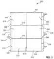
- FIG. 3illustrates a plan view of an example shroud in a flat state that can be used to implement the example self-erectable display of FIG. 1
- FIG. 4illustrates a plan view of an example support in a flat state that can be used to implement the example self-erectable display of FIG. 1 .
- FIG. 5illustrates a plan view of an example web including a plurality of example supports that can be used to implement the examples disclosed herein.
- FIG. 6illustrates an example flow diagram including processes of forming an example support that can used to implement the example self-erectable display of FIG. 1 .
- FIG. 7illustrates an example apparatus that can be used to produce the example self-erectable displays disclosed herein.
- FIG. 8illustrates a flowchart representative of machine readable instructions that may be executed to implement the apparatus of FIG. 7 .
- FIG. 9illustrates a processor platform to execute the instructions of FIG. 8 to implement the apparatus of FIG. 7 .
- the examples disclosed hereinrelate to self-erectable displays that can be used for point-of-sale advertising, providing information, or for other suitable purposes.
- the example self-erectable displaysmay be shipped to a customer in a folded, flat state.
- the example displaysmay include a biased support that is in a state of tension when the display is in the folded, flat state because forces imparted by the folded material of the display is greater than a force exerted by the biased support.
- the force being imparted on the biased supportis less than the force exerted by the biased support, thereby enabling the biased support to urge the display from the folded position to the erected position.
- an individualcan erect the example displays with little if any instruction and/or training.
- the example self-erectable displaysinclude an elongate, tubular shroud into which an internal structure is disposed.
- the shroudincludes an oblong cross-section having an example base coupled at an end and the internal structure includes an example biased support(s) coupled within the shroud.
- the cross-sectionmay be another shape including, for example, triangular, square, diamond, circular, or other semi-circular, elliptical, polygonal and/or non-polygonal shape(s).
- the example shroudis formed of an elongate substrate having top and bottom edges and first and second side edges.
- longitudinal lines of weakness and transverse lines of weaknessare defined in the shroud.
- the longitudinal lines of weaknessmay enable the example self-erectable display to be folded relatively flat and the transverse lines of weakness may enable the example self-erectable display to be folded about itself to form a z-fold, for example.
- the longitudinal and transverse lines of weaknessdefine central panels and outwardly facing flaps.
- the shroudis folded about a central line of weakness and the flaps are inwardly folded and coupled to enable the shroud to have an oblong cross-section and/or to define an aperture.
- notchesare defined between the flaps.
- the example shrouds disclosed hereinmay include any number of display panels (e.g., one, two, three, four, etc.) and/or any number of example supports (e.g., one example support per panel or more than one support per panel) disposed within the example shrouds depending on the application, etc. Also, in some examples, a support may be used for multiple panels.
- the example supportis formed of a substrate having top and bottom edges and first and second side edges.
- lines of weaknessare formed in the support to define four relatively larger panels and three relatively smaller panels.
- pairs of the larger panelsare disposed adjacent one another and one of the smaller panels is disposed on either side of each pair of the larger panels.
- notchesare formed between the larger panels that receive the elastic band.
- the supportis folded about the lines of weakness and the ends of the support are brought together and coupled.
- a tongue adjacent a side edge of the supportis received in an aperture defined adjacent another side edge of the support.
- the side edges of the supportmay be coupled in any suitable manner.
- an elastic bandis disposed about the support such that at least a first portion of the elastic band is disposed relatively parallel to the lines of weakness of the support and at least a second portion of the elastic band extends across an aperture defined by the tubular-shaped support.
- the dimensions of the supports and the elasticity of the bandsare selected to solely or fully brace the display in the erected or deployed position.
- the dimensions of the panels of the example support(s) and/or the elasticity and/or dimensions of the elastic band(s) used in connection with the example support(s)are tuned in combination and/or configured in such a way that some structure included on some other example supports may be excluded.
- the example biased supports disclosed hereinmay exclude a “stop” panel that controls the movement of different structures of those example supports relative to one another when an elastic band is coupled thereto. By excluding some of these additional structures in connection with the example supports disclosed herein, less material may be used to produce the example supports, thereby saving money in material and/or time producing and/or manufacturing the example supports disclosed herein.
- the example tubular supportis coupled within the example tubular shroud.
- the smaller support panelsare directly coupled to the shroud panels such that the lines of weakness of the support that separate the larger support panels face the flaps or the central lines of weakness of the shroud.
- the shroud panelsare outwardly biased by the smaller support panels via the elastic band.
- the lines of weakness that separate the larger support panelsare moved toward the ends of the shroud to enable the shroud panels to move toward one another and be disposed immediately adjacent one another.
- the shroud panelsWhen the shroud panels are disposed adjacent one another, the shroud may be folded about itself along the transverse lines of weakness to enable the display to be stored and/or shipped.
- the examples disclosed hereinenable a display to be folded flat for storage and to later self-erect into a tubular shape.
- FIG. 1illustrates an example self-erectable display 100 including a tubular-shaped shroud 102 coupled to a base 104 .
- the example self-erectable display 100may not include the base 104 such that the shroud 102 is used as an upright display without the base 104 .
- the shroud 102includes opposing first and second shroud panels 106 , 108 that are separated by a central line of weakness 109 and flaps 110 , 112 adjacent side edges 114 , 116 of the shroud 102 .
- the flaps 110 , 112are coupled together to enclose the shroud 102 and to enable adjacent longitudinal lines of weakness 118 , 120 to define an outward facing end of the tubular-shaped shroud 102 opposite the central line of weakness 109 that defines another outward facing end of the shroud 102 .
- example first and second biased supports 122 , 123are disposed within the example shroud 102 .
- FIG. 2shows a top view of the example self-erectable display 100 that illustrates the biased supports 122 , 123 coupled within the shroud 102 .
- the supports 122 , 123are the same or substantially the same size and/or shape.
- the first biased support 122includes first and second support panels 202 , 204 and third, fourth, fifth and sixth support panels 206 , 208 , 210 , 212 .
- the first support panel 202is coupled to an internal surface 214 of the first shroud panel 106 and the second support panel 204 is coupled to an internal surface 216 of the second shroud panel 108 .
- the support 122is formed using a substrate 217 including first, second, third, fourth, fifth and sixth lines of weakness 218 , 220 , 222 , 224 , 226 , 228 that define the first, second, third, fourth, fifth, sixth and seventh support panels 202 , 204 , 206 , 208 , 210 , 212 , 230 .
- notches 234are defined between the third and fourth panels 206 , 208 and notches 236 are defined between the fifth and sixth panels 210 , 212 .
- the first support panel 202is coupled to the seventh support panel 230 .
- the first and seventh support panels 202 , 230may be coupled in any suitable way such as with adhesive, glue, staple(s) and/or a tongue on one of the support panels 202 , 230 extending through an aperture on the other of the support panels 202 , 230 .
- Other suitable mechanical and/or chemical fastener(s)may additionally or alternatively be used.
- the elastic band 232is positioned about the support 122 and held in place, in this example, by being disposed within the notches 234 , 236 .
- the interaction between the elastic band 232 and the substrate 217urges the lines of weakness 220 , 226 toward one another and urges the support panels 202 , 204 away from one another.
- the support 122is formed into a tubular shape and the elastic band 232 is disposed about the substrate 217
- the first support panel 202is coupled to the first shroud panel 106 and the second support panel 204 is coupled to the second shroud panel 108 .
- the support panels 202 , 204may be coupled to the shroud panels 106 , 108 in any suitable way such as with adhesive, glue, tape, staples, and/or any other suitable mechanical and/or chemical fastener(s).
- the biasing force imposed by the elastic band 232outwardly urges the support panels 202 , 204 and, in turn, outwardly urges the shroud panels 106 , 108 to have an oblong cross-section when erected.
- the support panels 202 , 204 and the shroud panels 106 , 108are urged toward one another against the biasing force of the elastic band 232 .
- a usermay push the opposite sides of the shroud panels 106 , 108 together to flatten the display 100 .
- FIG. 3illustrates an example shroud 300 in a flat state that can be used to implement the example self-erectable display 100 of FIG. 1 .
- the example shroud 300is shown as being a single piece of substrate, in other examples, the shroud may be more than one piece of substrate that is coupled together to form the example self-erectable display as disclosed herein.
- the shroud 300includes top and bottom edges 302 , 304 and first and second side edges 306 , 308 .
- the shroud 300defines first, second and third longitudinal lines of weakness 310 , 312 , 314 and first and second transverse lines of weakness 316 , 318 .
- the longitudinal lines of weakness 310 , 312 , 314are substantially perpendicular relative to the transverse lines of weakness 316 , 318 .
- substantially perpendicularmeans between about 5-degrees from perpendicular and/or accounts for manufacturing tolerances.
- the lines of weakness 310 , 312 , 314 , 316 , 318define first, second, third, fourth, fifth and sixth central panels 320 , 322 , 324 , 326 , 328 , 330 and first, second, third, fourth, fifth and sixth flaps 332 , 334 , 336 , 338 , 340 , 342 .
- notches 344 , 346 , 348 , 350are defined by the shroud 300 between the flaps 332 , 334 , 336 , 338 , 340 , 342 .
- the shroud 300is folded about the second line of weakness 312 and the flaps 332 , 334 , 336 , 338 , 340 , 342 are inwardly folded about the first and third lines of weakness 310 , 314 to enable the opposing flaps 332 and 334 , 336 and 338 , 340 and 342 to be coupled to one another and disposed within an interior of the shroud 300 .
- the opposing flaps 332 and 334 , 336 and 338 , 340 and 342may be coupled in any suitable way using, for example, adhesive, glue, tape, staples, and/or any suitable mechanical and/or chemical fastener(s).
- the shroud 300may be folded (e.g., a z-fold or a c-fold) about the transverse axes 316 , 318 for shipping and/or storage.
- the notches 344 , 346 , 348 , 350may more easily enable the shroud 300 to be folded about the transverse axes 316 , 318 .
- FIG. 4illustrates an example support and/or insert 400 in a flat state that can be used to implement the example self-erectable display 100 of FIG. 1 .
- the support 400includes top and bottom edges 402 , 404 and first and second side edges 406 , 408 .
- lines of weakness 410 , 412 , 414 , 416 , 418 , 419 , 420are formed in the support 400 to define first, second, third and fourth larger panels 422 , 424 , 426 , 428 and first, second and third smaller panels 430 , 432 , 434 .
- the lines of weakness 410 , 412 , 414 , 416 , 418 , 419 , 420may be similar or different.
- the line of weakness 410may be a crease while the line of weakness 412 may be a die cut.
- the first and second larger panels 422 , 424are positioned between the first and second smaller panels 430 , 432 and the third and fourth larger panels 426 , 428 are positioned between the second and third smaller panels 432 , 434 .
- notches 436 , 438are formed between the first and second larger panels 422 , 424 and notches 440 , 442 are formed between the third and fourth larger panels 426 , 428 .
- the notches 436 , 438are v-shaped and oppose one another and the notches 440 , 442 are v-shaped and oppose one another.
- one or more of the notches 436 , 438 , 440 , 442may be differently shaped and/or the support 400 may define more or less notches than shown in this example.
- apertures through which the elastic member is threadedmay be used in addition to or alternatively to the notches 436 , 438 , 440 , 442 .
- the support 400is folded about the lines of weakness 410 , 414 , 416 , 418 , 419 , 420 and the sides 406 , 408 of the support 400 are brought together and coupled.
- a tongue 444 adjacent the second side 408is received in the aperture 412 defined adjacent the first side 406 of the support 400 .
- the smaller panels 430 , 434are further coupled using, for example, adhesive, glue, tape, a staple(s), and/or any suitable mechanical and/or chemical fastener(s).
- an elastic bandis disposed about the support 400 and within the notches 436 , 438 , 440 , 442 .
- portions of the elastic bandare disposed relatively parallel to the lines of weakness 414 , 419 that separate the respective larger panels 422 , 424 , 426 , 428 and portions of the elastic band extend between the lines of weakness 414 , 419 and/or the interior of the support.
- substantially parallelmeans between about 5-degrees of parallel and/or accounts for manufacturing tolerances.
- FIG. 5illustrates an example web 500 including the supports 400 that can be used to implement the examples disclosed herein.
- each of the supports 400may be die cut from a waste matrix 502 surrounding the supports 400 prior to forming the tubular support.
- FIG. 6is an example flow diagram 600 that illustrates example processes of assembling the example support 400 .
- Reference number 602illustrates the example support 400 in a flat or non-tubular state.
- the support 400is being folded about the lines of weakness 410 , 414 , 416 , 418 , 419 , 420 and the sides 406 , 408 of the support 400 are being brought together to position the tongue 444 within the aperture 412 to couple the sides 406 , 408 together.
- the fasteners 446 , 448e.g., double sided tape
- an elastic band 610is disposed about the support 400 and within the notches 436 , 438 , 440 , 442 .
- the elastic band 610is disposed relatively parallel to the lines of weakness 414 , 419 .
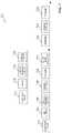
- FIG. 7represents an example apparatus 700 that can be used to produce the example self-erectable displays disclosed herein.
- the apparatus 700performs an in-line process that includes processes to produce an example support in accordance with the teachings of this disclosure, processes to produce an example shroud in accordance with the teachings of this disclosure and processes to produce an example self-erectable display in accordance with the teachings of this disclosure. While the processes disclosed below are described in connection with automatic processes, any and/or all of the processes disclosed may instead be implemented manually.
- the example apparatus 700includes elements to produce the example support including, for example, a substrate mover 702 , a die cutter 704 , a lines of weakness creator 706 , a folding station 708 , a coupler 709 and an elastic band applicator 710 .
- the example apparatus 700also includes elements to produce the example shroud including, for example, a substrate mover 712 , an imager 714 , a lines of weakness creator 716 and a shroud former 718 .
- the apparatus 700also includes elements to produce the example self-erectable display including, for example, an inserter 720 , a folding station 722 and a stacker 724 .
- the substrate mover 702feeds one or more pieces of substrate and/or a web of substrate into the apparatus 700 .
- the die cutter 704die cuts the substrate to form a support blank and a waste matrix
- the lines of weakness creator 706forms one or more lines of weakness on first and/or second sides of the support blank using a die(s), a cutting tool(s), a scoring tool(s), a slotting tool(s), etc.
- the folding station 708folds the support blank along one or more of the lines of weakness to form a tubular support.
- the coupler 709couples the ends of the support together by, for example, inserting a tongue on one end of the support into an aperture adjacent another end of the support.
- the coupler 709applies a fastener such as, for example, an adhesive, glue and/or tape to one or more of the smaller support panels to enable the tubular support to be coupled within the tubular shroud.
- the elastic band applicator 710positions an elastic band about the support within notches defined by the support. In some examples, the processes implemented by the folding station 708 , the coupler 709 and/or the elastic band applicator 710 are performed manually.
- the substrate mover 712feeds one or more pieces of substrate and/or a web of substrate into the apparatus 700 .
- the imager 714images a first and/or a second side of the shroud blank.
- the imagesmay include brand-related images and/or text, advertising-related images and/or text, point-of-purchase-related images and/or text, instructional images and/or text, and/or any other desired indicia.
- the lines of weakness creator 716forms one or more lines of weakness on first and/or second sides of the shroud blank using a die(s), a cutting tool(s), a scoring tool(s), a slotting tool(s), etc.
- the shroud former 718forms a tubular-shaped shroud by folding the shroud about a central line of weakness and coupling inwardly facing flaps. In some examples, the processes implemented by the shroud former 718 is performed manually.
- the inserter 720inserts and couples one or more example tubular supports within the example shroud.
- the folding station 722flattens and/or folds the self-erectable display about longitudinal axes of the shroud and/or folds the self-erectable display about transverse axes of the shroud for storage and/or shipping.
- the stacker 724stacks self-erectable displays for storage and/or shipping, etc. In some examples, the processes implemented by the inserter 720 , the folding station 722 and/or the stacker 724 are performed manually.
- stations and/or portions including the example substrate mover 702 , the example die cutter 704 , the example lines of weakness creator 706 , the example folding station 708 , the example coupler 709 , the example elastic band applicator 710 , the example substrate mover 712 , the example imager 714 , the example lines of weakness creator 716 , the example shroud former 718 , the example inserter 720 , the example folding station 722 , the example stacker 724 of the apparatus 700are depicted in a particular order, the stations and/or portions including the example substrate mover 702 , the example die cutter 704 , the example lines of weakness creator 706 , the example folding station 708 , the example coupler 709 , the example elastic band applicator 710 , the example substrate mover 712 , the example imager 714 , the example lines of weakness creator 716 , the example shroud former 718 , the example inserter 720 , the example folding station 722 , the example stacker 724
- the order of the stations and/or portions including the example substrate mover 702 , the example die cutter 704 , the example lines of weakness creator 706 , the example folding station 708 , the example coupler 709 , the example elastic band applicator 710 , the example substrate mover 712 , the example imager 714 , the example lines of weakness creator 716 , the example shroud former 718 , the example inserter 720 , the example folding station 722 , the example stacker 724may be changed, and/or some of the stations and/or portions including the example substrate mover 702 , the example die cutter 704 , the example lines of weakness creator 706 , the example folding station 708 , the example coupler 709 , the example elastic band applicator 710 , the example substrate mover 712 , the example imager 714 , the example lines of weakness creator 716 , the example shroud former 718 , the example inserter 720 , the example folding station 722 , the example stacker 724
- FIG. 8A flowchart representative of example machine readable instructions for implementing the apparatus 700 of FIG. 7 is shown in FIG. 8 .
- the machine readable instructionscomprise a program for execution by a processor such as the processor 912 shown in the example processor platform 900 discussed below in connection with FIG. 9 .
- the programmay be embodied in software stored on a tangible computer readable storage medium such as a CD-ROM, a floppy disk, a hard drive, a digital versatile disk (DVD), a Blu-ray disk, or a memory associated with the processor 912 , but the entire program and/or parts thereof could alternatively be executed by a device other than the processor 912 and/or embodied in firmware or dedicated hardware.
- example programis described with reference to the flowchart illustrated in FIG. 8 , many other methods of implementing the example apparatus 700 may alternatively be used. For example, the order of execution of the blocks may be changed, and/or some of the blocks described may be changed, eliminated, or combined.
- the example processes of FIG. 8may be implemented using coded instructions (e.g., computer and/or machine readable instructions) stored on a tangible computer readable storage medium such as a hard disk drive, a flash memory, a read-only memory (ROM), a compact disk (CD), a digital versatile disk (DVD), a cache, a random-access memory (RAM) and/or any other storage device or storage disk in which information is stored for any duration (e.g., for extended time periods, permanently, for brief instances, for temporarily buffering, and/or for caching of the information).
- a tangible computer readable storage mediumis expressly defined to include any type of computer readable storage device and/or storage disk and to exclude propagating signals and transmission media.
- tangible computer readable storage mediumand “tangible machine readable storage medium” are used interchangeably. Additionally or alternatively, the example processes of FIG. 8 may be implemented using coded instructions (e.g., computer and/or machine readable instructions) stored on a non-transitory computer and/or machine readable medium such as a hard disk drive, a flash memory, a read-only memory, a compact disk, a digital versatile disk, a cache, a random-access memory and/or any other storage device or storage disk in which information is stored for any duration (e.g., for extended time periods, permanently, for brief instances, for temporarily buffering, and/or for caching of the information).
- coded instructionse.g., computer and/or machine readable instructions
- a non-transitory computer and/or machine readable mediumsuch as a hard disk drive, a flash memory, a read-only memory, a compact disk, a digital versatile disk, a cache, a random-access memory and/or any other storage device or storage disk in which information is
- non-transitory computer readable mediumis expressly defined to include any type of computer readable storage device and/or storage disk and to exclude propagating signals and transmission media.
- phrase “at least”is used as the transition term in a preamble of a claim, it is open-ended in the same manner as the term “comprising” is open ended.
- the process of FIG. 8 directed toward producing an example supportincludes die cutting a first substrate (e.g., the support 400 ) (block 802 ) using, for example, the die cutter 704 that die cuts one or more pieces of substrate and/or a web of substrate to form a support blank and a waste matrix.
- Lines of weaknessare formed on the support blank (block 804 ) by, for example, the lines of weakness creator 706 forming one or more lines of weakness on first and/or second sides of the support blank using a die(s), a cutting tool(s), a scoring tool(s), a slotting tool(s), etc.
- the support blankis folded about the lines of weakness (block 806 ) by, for example, the folding station 708 that folds the support blank along the lines of weakness to form a tubular support.
- the ends of the supportare coupled to form the support (block 808 ) using, for example, the coupler 709 that couples the ends of the support together by inserting a tongue adjacent one end of the support into an aperture adjacent another end of the support.
- An elastic bandis applied around the support (block 810 ) using, for example, the elastic band applicator 710 that positions the elastic band about the support such that the elastic band extends between top and bottom edges of the support and across an aperture defined by the tubular support.
- Fastener(s)such as, for example, an adhesive (e.g., double sided tape) is applied to an exterior surface(s) of the support (block 812 ) using, for example, the coupler 708 that applies adhesive to one or more of the smaller support panels.
- an adhesivee.g., double sided tape
- the process of FIG. 8 directed toward producing an example shroudincludes imaging a second substrate (e.g., the shroud 300 ) (block 814 ) using, for example, the imager 714 that images a first and/or second side of the shroud with, for example, brand-related images and/or text, advertising-related images and/or text, point-of-purchase-related images and/or text, instructional images and/or other text, indicia and/or images.
- Lines of weaknessare formed on the shroud blank (block 816 ) using, for example, the lines of weakness creator 716 that forms one or more lines of weakness on first and/or second sides of the shroud blank using a die(s), a cutting tool(s), a scoring tool(s), a slotting tool(s), etc.
- the tubular shroudis formed (block 818 ) using, for example, the shroud former 718 that folds the shroud about a central line of weakness and couples inwardly facing flaps using, for example, adhesive, glue and/or a staple(s).
- the process of FIG. 8 directed toward producing an example self-erectable display in accordance with the teachings of this disclosurealso includes inserting a support(s) within the shroud (block 820 ) using, for example, the inserter 720 that inserts and couples the support(s) within the shroud such that outwardly biased support panels expand the opposing shroud panels to enable the shroud to have an oblong cross-section when erected.
- the self-erectable displayis folded along lines of weakness (block 822 ) using, for example, the folding station 722 that flattens and/or folds the self-erectable display about longitudinal axes of the shroud and/or transverse axes of the shroud for storage and/or shipping.
- the folded self-erectable displayis stacked (block 824 ) using, for example, the stacker 724 that stacks the self-erectable displays for storage and/or shipping, etc.
- FIG. 9is a block diagram of an example processor platform 900 capable of executing the instructions of FIG. 8 to implement the apparatus 700 of FIG. 7 .
- the processor platform 800can be, for example, a server, a personal computer, a mobile device (e.g., a tablet such as an iPadTM), an Internet appliance, a DVD player, a CD player, a digital video recorder, a Blu-ray player, or any other type of computing device.
- the processor platform 900 of the illustrated exampleincludes a processor 912 .
- the processor 912 of the illustrated exampleis hardware.
- the processor 912can be implemented by one or more integrated circuits, logic circuits, microprocessors or controllers from any desired family or manufacturer.
- the processor 912 of the illustrated exampleincludes a local memory 913 (e.g., a cache).
- the processor 912 of the illustrated exampleis in communication with a main memory including a volatile memory 914 and a non-volatile memory 916 via a bus 918 .
- the volatile memory 914may be implemented by Synchronous Dynamic Random Access Memory (SDRAM), Dynamic Random Access Memory (DRAM), RAMBUS Dynamic Random Access Memory (RDRAM) and/or any other type of random access memory device.
- the non-volatile memory 916may be implemented by flash memory and/or any other desired type of memory device. Access to the main memory 914 , 916 is controlled by a memory controller.
- the processor platform 900 of the illustrated examplealso includes an interface circuit 920 .
- the interface circuit 920may be implemented by any type of interface standard, such as an Ethernet interface, a universal serial bus (USB), and/or a PCI express interface.
- one or more input devices 922are connected to the interface circuit 920 .
- the input device(s) 922permit(s) a user to enter data and commands into the processor 912 .
- the input device(s)can be implemented by, for example, an audio sensor, a microphone, a camera (still or video), a keyboard, a button, a mouse, a touchscreen, a track-pad, a trackball, isopoint and/or a voice recognition system.
- One or more output devices 924are also connected to the interface circuit 920 of the illustrated example.
- the output devices 924can be implemented, for example, by display devices (e.g., a light emitting diode (LED), an organic light emitting diode (OLED), a liquid crystal display, a cathode ray tube display (CRT), a touchscreen, a tactile output device, a light emitting diode (LED), a printer and/or speakers).
- the interface circuit 920 of the illustrated examplethus, typically includes a graphics driver card, a graphics driver chip or a graphics driver processor.
- the interface circuit 920 of the illustrated examplealso includes a communication device such as a transmitter, a receiver, a transceiver, a modem and/or network interface card to facilitate exchange of data with external machines (e.g., computing devices of any kind) via a network 926 (e.g., an Ethernet connection, a digital subscriber line (DSL), a telephone line, coaxial cable, a cellular telephone system, etc.).
- a network 926e.g., an Ethernet connection, a digital subscriber line (DSL), a telephone line, coaxial cable, a cellular telephone system, etc.
- the processor platform 900 of the illustrated examplealso includes one or more mass storage devices 928 for storing software and/or data.
- mass storage devices 928include floppy disk drives, hard drive disks, compact disk drives, Blu-ray disk drives, RAID systems, and digital versatile disk (DVD) drives.
- the coded instructions 932 of FIG. 8may be stored in the mass storage device 928 , in the volatile memory 914 , in the non-volatile memory 916 , and/or on a removable tangible computer readable storage medium such as a CD or DVD.
- an example apparatusincludes a shroud having a first shroud panel opposite a second shroud panel; a support coupled within the shroud, the support including a top edge, a bottom edge, and first and second sides edges, the first side edge coupled adjacent the second side edge; and an elastic band to be coupled to the support and outwardly bias the shroud to enable the shroud to have the oblong cross-section when erected, a portion of the elastic band being substantially parallel to a longitudinal axis of the support.
- the top and bottom edgesdefine notches into which the elastic band is disposed.
- the supportfurther includes a tongue adjacent the first edge and an aperture adjacent the second edge, the aperture to receive the tongue to couple the first and second side edges.
- the supportis folded to define first and second support panels, the first support panel to be coupled to the first shroud panel and the second support panel to be coupled to the second shroud panel.
- the supportfurther includes a notch defined by the top edge or the bottom edge into which the elastic band is to be disposed, the notch positioned between the first support panel and the second support panel.
- the shroudfurther includes a first shroud line of weakness and a second shroud line of weakness, the first shroud line of weakness separating the first shroud panel and the second shroud panel at a first end of the shroud, the second shroud line of weakness separating the first shroud panel and the second shroud panel at a second end of the shroud.
- the shroudis foldable about the first and second shroud lines of weakness by urging the first shroud panel toward the second shroud panel against a biasing force of the elastic band.
- the shroudfurther includes inwardly facing flaps that are coupled to enable the shroud to have the oblong cross-section when erected.
- the first shroud panelincludes a first transverse line of weakness and the second shroud panel includes a second transverse line of weakness, the first and second transverse lines of weakness being substantially within a plane of the shroud to enable the first and second lines of weakness to be immediately adjacent one another when the first and second shroud panels are being folded about the first and second transverse lines of weakness.
- the shroudis foldable about the first and second transverse lines of weakness.
- the apparatusis a self-erecting display.
- An example apparatusincludes a support to be coupled within a self-erecting display, the support including a top edge, a bottom edge, and first and second sides edges, the first side edge coupled adjacent the second side edge; and an elastic band to be coupled to the support and outwardly bias the display when the support is coupled therein, a portion of the elastic band being substantially parallel a longitudinal axis of the support.
- the top and bottom edgesdefine notches into which the elastic band is disposed.
- the supportfurther includes a tongue adjacent the first edge and an aperture adjacent the second edge, the aperture to receive the tongue to couple the first and second side edges.
- the supportis folded to define first and second support panels, the first support panel to be coupled to the first shroud panel and the second support panel to be coupled to the second shroud panel.
- the supportfurther includes a notch defined by the top edge or the bottom edge into which the elastic band is to be disposed, the notch positioned between the first support panel and the second support panel.
- An example apparatusincludes a shroud including a first shroud panel, a second shroud panel coupled to the first shroud panel, and an interior formed between the first shroud panel and the second shroud panel; a support disposed in the interior of the shroud, the support including a top edge, a bottom edge, and first and second sides edges, the first side edge coupled adjacent the second side edge, and one of the first side edge or the second side edge coupled to one of the first shroud panel or the second shroud panel; and a biasing member coupled to the support such that at least a portion of the biasing member is substantially parallel to a longitudinal axis of the support, the biasing member to cause a portion of the first shroud panel to separate from a portion of the second shroud panel.
- the interiorhas an oblong cross-section.
- the biasing membersurrounds the support.
- the biasing memberis an elastic band.
- the supportis a first support, further including a second support disposed in the interior of the shroud spaced from the first support.
- the top edgeis a first top edge and the bottom edge is a first bottom edge
- the second supportincludes a second top edge, a second bottom edge, and third and fourth sides edges, the third side edge coupled adjacent the fourth side edge, and one of the third side edge or the fourth side edge coupled to one of the first shroud panel or the second shroud panel.
- the examples self-erectable displays disclosed hereinmay be deployed from a storage state to an erected or deployed state with little effort.
- a usersuch as, for example, a shop clerk, can remove a folded display from an outer packaging or container and unfold the display along the lines of weakness disclosed above.
- the force imparted by the biasing member(s) on the internal supportsautomatically forces the outer shroud panels to expand away from one of other as disclosed above.
- the displaysimply pops open by itself.
- the deployment of the displayis then complete and the display is ready for placement in a desired location and/or coupling to an optional base should additional stability be desired.
- a shroudincluding a first shroud panel opposite a second shroud panel, the first shroud panel and the second shroud panel coupled at a first end and a second end of the shroud; a support coupled within the shroud and centrally disposed between the first shroud panel and the second shroud panel and spaced from the first and second ends of the shroud, the support including a top edge, a bottom edge, and first and second sides edges, the first side edge coupled adjacent the second side edge; an elastic band is to be coupled to the support and to outwardly bias the shroud to enable the shroud to have an oblong cross-section when erected; and when the elastic band is coupled to the support, the elastic band surrounds the support engaging the top edge and the bottom edge to position a portion of the elastic band substantially parallel to a longitudinal axis of the support.
- the top and bottom edgesdefine notches into which the elastic band is to be disposed.
- the supportfurther including a tongue adjacent the first edge and an aperture adjacent the second edge, the aperture to receive the tongue to couple the first and second side edges.
- the supportis folded to define first and second support panels, the first support panel to be coupled to the first shroud panel and the second support panel to be coupled to the second shroud panel.
- the apparatusincludes a notch defined by the top edge or the bottom edge into which the elastic band is to be disposed, the notch positioned between the first support panel and the second support panel.
- the shroudfurther includes a first shroud line of weakness and a second shroud line of weakness, the first shroud line of weakness separating the first shroud panel and the second shroud panel at the first end of the shroud, the second shroud line of weakness separating the first shroud panel and the second shroud panel at the second end of the shroud.
- the shroudis foldable about the first and second shroud lines of weakness by urging the first shroud panel toward the second shroud panel against a biasing force of the elastic band.
- the shroudfurther includes inwardly facing flaps that are coupled to enable the shroud to have the oblong cross-section when erected.
- the first shroud panelincludes a first transverse line of weakness and the second shroud panel includes a second transverse line of weakness, the first and second transverse lines of weakness being substantially within a plane of the shroud to enable the first and second transverse lines of weakness to be immediately adjacent one another when the first and second shroud panels are being folded about the first and second transverse lines of weakness.
- the shroudis foldable about the first and second transverse lines of weakness.
- the apparatusis a self-erecting display.
- An includes apparatusincludes a shroud including a first shroud panel, a second shroud panel coupled to the first shroud panel, and an interior formed between the first shroud panel and the second shroud panel; a support disposed in the interior of the shroud, the support including a top edge, a bottom edge, and first and second sides edges, the first side edge coupled adjacent the second side edge, and one of the first side edge or the second side edge coupled to one of the first shroud panel or the second shroud panel; and a biasing member coupled to the support such that the biasing member surrounds the support engaging the top edge and the bottom edge and opposing first and second support panels to position a portion of the biasing member substantially parallel to a longitudinal axis of the support, the biasing member to cause a portion of the first shroud panel to separate from a portion of the second shroud panel.
- the interiorhas an oblong cross-section.
- the biasing memberis an elastic band.
- the supportis a first support, further including a second support disposed in the interior of the shroud spaced from the first support.
- the top edgeis a first top edge and the bottom edge is a first bottom edge
- the second supportincludes a second top edge, a second bottom edge, and third and fourth sides edges, the third side edge coupled adjacent the fourth side edge, and one of the third side edge or the fourth side edge coupled to one of the first shroud panel or the second shroud panel.
- the supportincludes a first support panel and a second support panel, the first support panel coupled to the first shroud panel, the second support panel coupled to the second shroud panel, the first support panel substantially parallel to the second support panel.
- An example apparatusincludes a shroud including a first shroud panel opposite a second shroud panel; a support coupled within the shroud, the support including a first support panel and a second support panel, the first support panel coupled to the first shroud panel, the second support panel coupled to the second shroud panel, the first support panel substantially parallel to the second support panel when the support is in an expanded state, the support including a top edge, a bottom edge, and first and second sides edges, the first side edge coupled adjacent the second side edge; and an elastic band to be coupled to and to surround the support and to outwardly bias the shroud to enable the shroud to have an oblong cross-section when erected, a portion of the elastic band being substantially parallel to a longitudinal axis of the support.
Landscapes
- Physics & Mathematics (AREA)
- General Physics & Mathematics (AREA)
- Engineering & Computer Science (AREA)
- Theoretical Computer Science (AREA)
- Devices For Indicating Variable Information By Combining Individual Elements (AREA)
- Display Racks (AREA)
Abstract
Description
Claims (14)
Priority Applications (1)
| Application Number | Priority Date | Filing Date | Title |
|---|---|---|---|
| US16/421,116US10685588B2 (en) | 2015-05-11 | 2019-05-23 | Self-erectable displays and methods of making such self-erectable displays |
Applications Claiming Priority (3)
| Application Number | Priority Date | Filing Date | Title |
|---|---|---|---|
| US14/709,285US9812038B2 (en) | 2015-05-11 | 2015-05-11 | Self-erectable displays and methods of making such self-erectable displays |
| US15/786,405US10319261B2 (en) | 2015-05-11 | 2017-10-17 | Self-erectable displays and methods of making such self-erectable displays |
| US16/421,116US10685588B2 (en) | 2015-05-11 | 2019-05-23 | Self-erectable displays and methods of making such self-erectable displays |
Related Parent Applications (1)
| Application Number | Title | Priority Date | Filing Date |
|---|---|---|---|
| US15/786,405ContinuationUS10319261B2 (en) | 2015-05-11 | 2017-10-17 | Self-erectable displays and methods of making such self-erectable displays |
Publications (2)
| Publication Number | Publication Date |
|---|---|
| US20190279534A1 US20190279534A1 (en) | 2019-09-12 |
| US10685588B2true US10685588B2 (en) | 2020-06-16 |
Family
ID=57277551
Family Applications (3)
| Application Number | Title | Priority Date | Filing Date |
|---|---|---|---|
| US14/709,285ActiveUS9812038B2 (en) | 2015-05-11 | 2015-05-11 | Self-erectable displays and methods of making such self-erectable displays |
| US15/786,405ActiveUS10319261B2 (en) | 2015-05-11 | 2017-10-17 | Self-erectable displays and methods of making such self-erectable displays |
| US16/421,116ActiveUS10685588B2 (en) | 2015-05-11 | 2019-05-23 | Self-erectable displays and methods of making such self-erectable displays |
Family Applications Before (2)
| Application Number | Title | Priority Date | Filing Date |
|---|---|---|---|
| US14/709,285ActiveUS9812038B2 (en) | 2015-05-11 | 2015-05-11 | Self-erectable displays and methods of making such self-erectable displays |
| US15/786,405ActiveUS10319261B2 (en) | 2015-05-11 | 2017-10-17 | Self-erectable displays and methods of making such self-erectable displays |
Country Status (1)
| Country | Link |
|---|---|
| US (3) | US9812038B2 (en) |
Cited By (2)
| Publication number | Priority date | Publication date | Assignee | Title |
|---|---|---|---|---|
| US10755605B2 (en) | 2017-01-25 | 2020-08-25 | R.R. Donnelley & Sons Company | Polygonal display and method for forming the same |
| US11227511B2 (en) | 2016-08-05 | 2022-01-18 | R. R. Donnelley & Sons Company | Pop-up display and pop-up display locking mechanism therefore |
Families Citing this family (11)
| Publication number | Priority date | Publication date | Assignee | Title |
|---|---|---|---|---|
| US9779640B2 (en) | 2015-05-11 | 2017-10-03 | R.R. Donnelley & Sons Company | Self-erectable displays and methods of making such self-erectable displays |
| US9812038B2 (en) | 2015-05-11 | 2017-11-07 | R.R. Donnelley & Sons Company | Self-erectable displays and methods of making such self-erectable displays |
| US9734734B2 (en) | 2015-05-13 | 2017-08-15 | R.R. Donnelley & Sons Company | Self-erectable displays and methods of making such self-erectable displays |
| US10008138B2 (en) | 2015-12-31 | 2018-06-26 | R.R. Donnelley & Sons Company | Self-erectable displays and methods of making such self-erectable displays |
| US9978292B2 (en) | 2016-01-25 | 2018-05-22 | R. R. Donnelley & Sons Company | Self-erectable displays and methods of making such self-erectable displays |
| US9715840B1 (en) | 2016-08-05 | 2017-07-25 | R.R. Donnelley & Sons Company | Self-erectable display and automatic locking mechanism for a self-erectable display |
| US10170020B2 (en) | 2016-09-09 | 2019-01-01 | R.R. Donnelley & Sons Company | Pop-up display with translating stop member |
| US10573202B2 (en)* | 2016-09-09 | 2020-02-25 | R.R. Donnelley & Sons Company | Self-erectable display with free floating stop and method for forming the same |
| US10210779B2 (en) | 2017-03-16 | 2019-02-19 | R.R. Donnelley & Sons Company | Polyhedral automatic pop-up display |
| US10741109B2 (en) | 2017-08-29 | 2020-08-11 | R.R. Donnelley & Sons Company | Quadrilateral display and method for forming the same |
| US10706747B2 (en) | 2018-11-27 | 2020-07-07 | R.R. Donnelley & Sons Company | Pyramidical displays and methods for forming the same |
Citations (159)
| Publication number | Priority date | Publication date | Assignee | Title |
|---|---|---|---|---|
| US822841A (en) | 1905-04-10 | 1906-06-05 | William F Hill | Advertising-carton. |
| US956916A (en) | 1909-11-01 | 1910-05-03 | Ketterlinus Lithographic Mfg Company | Display-card. |
| US1028147A (en) | 1911-02-04 | 1912-06-04 | American Lithographic Co | Collapsible display device. |
| US1545771A (en) | 1924-07-05 | 1925-07-14 | Illinois Glass Company | Display carton |
| US1576672A (en) | 1924-04-28 | 1926-03-16 | Schmidt Lithograph Company | Advertising display easel |
| US1656341A (en) | 1926-10-06 | 1928-01-17 | Atlantic Lithographic And Prin | Advertising device |
| US1670464A (en) | 1923-12-08 | 1928-05-22 | Harry V Marsh | Display card |
| US1687616A (en) | 1925-08-24 | 1928-10-16 | Joseph G Huye | Display stand |
| US1902566A (en) | 1930-11-08 | 1933-03-21 | Harry V Marsh | Display rack |
| GB463574A (en) | 1935-10-19 | 1937-04-02 | Robert Hutchison Anderson | Improvements in or relating to model and structural articles available also for containers and display purposes |
| US2108349A (en) | 1936-06-12 | 1938-02-15 | Magill Weinsheimer Company | Advertising device and mailing tube |
| US2113288A (en) | 1937-03-31 | 1938-04-05 | Harry A Berger | Container |
| US2142826A (en) | 1937-11-12 | 1939-01-03 | Juan P Rosello | Advertising display holder |
| US2153460A (en) | 1937-10-08 | 1939-04-04 | Giles Frederick Kenwood | Show card and the like |
| US2210317A (en) | 1936-02-12 | 1940-08-06 | Bailey Meter Co | Indicating and positioning system |
| US2283406A (en) | 1941-06-21 | 1942-05-19 | Charles J Bacon | Collapsible display receptacle |
| US2290144A (en) | 1940-06-20 | 1942-07-14 | Cons Mounting And Finishing Co | Pasteboard floor-display stand |
| US2404089A (en) | 1940-03-30 | 1946-07-16 | Raphael C Pollock | Display device |
| US2601374A (en) | 1947-02-24 | 1952-06-24 | Guy E Ditzler | Surprise display |
| US2637924A (en) | 1948-07-01 | 1953-05-12 | Herman H Hutt | Display device |
| GB740577A (en) | 1952-07-10 | 1955-11-16 | Amelie Graebener Heer | An improved container, more particularly a display and sale carton |
| US2728461A (en) | 1952-04-04 | 1955-12-27 | Richard E Paige | Display device |
| GB743378A (en) | 1953-09-28 | 1956-01-11 | Thompson And Norris Mfg Compan | Improvements in or relating to display stands and blanks for the production thereof |
| US2773324A (en) | 1952-09-27 | 1956-12-11 | Chicago Cardboard Company | Frame type display device |
| US2833074A (en) | 1955-08-10 | 1958-05-06 | Nicholas G Jannes | Pop-up display |
| US2892276A (en) | 1958-07-16 | 1959-06-30 | Lawrence U Nelson | Display device |
| GB824004A (en) | 1957-01-17 | 1959-11-25 | Peter Anthony Jeffreys | Improved show card |
| US2918178A (en) | 1958-04-08 | 1959-12-22 | New Haven Board And Carton Com | Display stands |
| FR1254983A (en) | 1960-01-16 | 1961-03-03 | Thibaud & Cie G | Foldable display |
| US2984920A (en) | 1960-01-05 | 1961-05-23 | Three dimensional greeting card | |
| US3015898A (en) | 1958-09-08 | 1962-01-09 | Upjohn Co | Advertising display |
| US3091877A (en) | 1961-03-03 | 1963-06-04 | Norcross Inc | Display device |
| US3234682A (en) | 1962-11-02 | 1966-02-15 | Winthrop Atkins Co Inc | Self-erecting building block |
| GB1034280A (en) | 1964-05-14 | 1966-06-29 | Stembridge Thompson Ltd | Improvements in display devices |
| US3267597A (en) | 1964-01-27 | 1966-08-23 | Nicholas G Jannes | Hollow foldable display |
| US3302321A (en) | 1963-08-16 | 1967-02-07 | Wallace G Walker | Foldable structure |
| US3571958A (en) | 1969-01-03 | 1971-03-23 | Trevor Stevens | Blanks and constructions made therewith |
| GB1272187A (en) | 1970-01-28 | 1972-04-26 | Graphic Trend Ass Ltd | Improvements in and relating to display stands for advertising material |
| US3666607A (en) | 1968-09-03 | 1972-05-30 | Joel J Weissman | Blank for constructing solid forms |
| US3665669A (en) | 1970-09-18 | 1972-05-30 | Nasa | Foldable construction block |
| GB1317155A (en) | 1969-06-03 | 1973-05-16 | Stenven Secuda Associates Ltd | Blanks and constructions made therewith |
| FR2210317A5 (en) | 1972-12-12 | 1974-07-05 | Middlebrook Promotional | |
| FR2232259A5 (en) | 1973-06-01 | 1974-12-27 | Vasseur Cartonnages R | Folding display stand - erected by folding and glueing to form column holding display panels |
| FR2233912A5 (en) | 1973-06-12 | 1975-01-10 | Tyrode S A | |
| DE2658506A1 (en) | 1976-01-12 | 1978-01-12 | Stabernack Gmbh Gustav | Publicity display with curved display surface - has side panels coupled together at rear of display |
| US4234148A (en) | 1979-01-19 | 1980-11-18 | Damon Corporation | Display stand |
| FR2571949A1 (en) | 1985-10-22 | 1986-04-25 | Leprince Claude | Folding display case having an automatic unfolding capability |
| FR2574968A1 (en) | 1984-12-19 | 1986-06-20 | Fritsch Rene | Cardboard panel, intended more particularly for advertising |
| US4610363A (en) | 1985-03-04 | 1986-09-09 | Paul Flum Ideas, Inc. | Container assembly for storage and display of articles |
| US4619426A (en) | 1985-05-22 | 1986-10-28 | Drueck Jr Fred | Self-erecting hollow structure |
| US4750283A (en) | 1987-01-06 | 1988-06-14 | Ron Halpern | Picture display device |
| US4770379A (en) | 1987-06-03 | 1988-09-13 | Estvold Terry L | Disposable toothbrush holder |
| US4773622A (en) | 1987-07-07 | 1988-09-27 | Graphics 3, Inc. | Self-erecting display device |
| US4774780A (en) | 1986-09-17 | 1988-10-04 | Structural Graphics Inc. | Bent resilient leaf spring pop-up display assemblies |
| US4790714A (en) | 1986-01-15 | 1988-12-13 | Abraham Schnapp | Expandable cube toy |
| US4854060A (en) | 1987-02-27 | 1989-08-08 | Manco Inc. | Self-erecting photo display |
| US4940199A (en) | 1989-06-23 | 1990-07-10 | Hall Anson L | Support for eating utensils |
| US4984848A (en) | 1988-12-07 | 1991-01-15 | Scalisi Phillip M | Collapsible disposable chair |
| FR2650907A1 (en) | 1989-08-09 | 1991-02-15 | Saint Clair Cartonnage | Structure which can be folded flat, made of a semi-rigid material, for presenting information |
| US4993846A (en) | 1989-07-21 | 1991-02-19 | Sidney Diamond | Soft bag and expander |
| US5000717A (en) | 1990-04-02 | 1991-03-19 | Pfeiffer Werner B | Toy building component |
| DE4005925A1 (en) | 1990-02-25 | 1991-10-24 | Arthur Frank | Cardboard advertisement support - is double-skinned with slotted wall for insertion of additional support |
| US5090349A (en) | 1991-02-14 | 1992-02-25 | American Allsafe Company | Traffic safety cone |
| FR2680030A1 (en) | 1991-07-31 | 1993-02-05 | Euro Plv | Cardboard display stand |
| US5193466A (en) | 1992-04-17 | 1993-03-16 | Diversified Advertising, Inc. | Corrugated board pop up display |
| US5197631A (en) | 1991-12-06 | 1993-03-30 | Eiichi Mishima | Mechanism for automatically pushing up tissues |
| FR2691621A1 (en) | 1992-06-01 | 1993-12-03 | Sca Promotion France | Folding display stand for advertising - has elastic cords and flaps folded inwards to keep stand open and side panels folded outwards to fold it up |
| US5297677A (en) | 1993-03-15 | 1994-03-29 | Alfred Burian | Sanitary toothbrush holder |
| DE4314654A1 (en) | 1993-05-04 | 1994-11-17 | Goos Juergen Dipl Ing Designer | Bill post |
| DK9500055U3 (en) | 1995-02-13 | 1995-05-15 | Peter Koefoed | Collapsible display |
| US5416997A (en) | 1993-07-28 | 1995-05-23 | Dyment Ltd. | Collapsible display |
| DE9320993U1 (en) | 1993-05-04 | 1995-08-03 | Goos, Jürgen, 68794 Oberhausen-Rheinhausen | Poster stand |
| DK9500277U3 (en) | 1995-07-19 | 1995-09-22 | Soeren Strudahl | Curved exhibition wall |
| US5454180A (en) | 1993-02-26 | 1995-10-03 | Volpe; James R. | Pre-assembled self erecting display |
| US5467547A (en) | 1993-11-10 | 1995-11-21 | Graphic Communications, Inc. | Self-erecting display stand that automatically dimensionalizes front panels |
| FR2730148A1 (en) | 1995-02-07 | 1996-08-09 | Souquiere Bernard Charles Pier | Sectional frame for exhibition |
| WO1996034379A1 (en) | 1995-04-24 | 1996-10-31 | Erich Raith | Adjustable wall component for display purposes |
| FR2735264A1 (en) | 1995-06-09 | 1996-12-13 | Athem | Advertising or display panel with interchangeable surface sheet |
| US5632390A (en) | 1995-12-22 | 1997-05-27 | Podergois; Jeffrey A. | Foldable display assembly |
| FR2745109A1 (en) | 1996-02-21 | 1997-08-22 | Mignot Graphie Sa | Free=standing notice board |
| US5752649A (en) | 1995-03-30 | 1998-05-19 | Southpac Trust International, Inc. | Self-erecting container with liner |
| US5758438A (en) | 1995-12-06 | 1998-06-02 | Crowell; Christopher S. | Printing system and method for individually creating three-dimensional displays |
| US5778959A (en) | 1996-08-23 | 1998-07-14 | Guetschow; Keith | Portable display screen |
| US5787621A (en) | 1996-04-10 | 1998-08-04 | Leksell; Carl | Display stand |
| FR2760880A1 (en) | 1997-03-13 | 1998-09-18 | Hotel Francois L | Folding display unit, e.g. for advertising purposes |
| FR2760801A1 (en) | 1997-03-11 | 1998-09-18 | One Design | Assembly system for modular components, e.g. of produce or document display stand |
| FR2760802A1 (en) | 1997-03-11 | 1998-09-18 | One Design | Assembly system e.g. for components of product or document display stands |
| US5809673A (en) | 1996-10-04 | 1998-09-22 | American Slide-Chart Corporation | Pop up display device |
| US5868367A (en) | 1996-10-15 | 1999-02-09 | Arrow Art Finishers, L.L.C. | Rapid-deployment display stand |
| FR2770320A1 (en) | 1997-10-23 | 1999-04-30 | Aps Visuel | Notice or poster display unit |
| WO1999036900A1 (en) | 1998-01-16 | 1999-07-22 | Frigg Aps | A display means, a method of manufacturing same, a display system, and a method of displaying |
| US5937553A (en) | 1997-03-18 | 1999-08-17 | Maran; Daniel L. | Pop-up polyhedron greeting card |
| US5966857A (en) | 1997-10-16 | 1999-10-19 | Adbox, Inc. | Advertising display |
| US6311418B1 (en) | 1995-12-06 | 2001-11-06 | Christopher S. Crowell | Printing system for individually creating three-dimensional displays |
| WO2002095719A2 (en) | 2001-05-18 | 2002-11-28 | L Hotel Francois | Support for information display unit with at least one display surface |
| US6497601B1 (en) | 2002-04-24 | 2002-12-24 | Eric Ward | Folding three dimensional construction |
| JP2003530602A (en) | 2000-07-11 | 2003-10-14 | ロテル、フランソワ | Self-supporting folding information presentation structure |
| WO2004044867A1 (en) | 2002-11-12 | 2004-05-27 | L Hotel Francois | Object display device |
| US20040111930A1 (en) | 2002-09-17 | 2004-06-17 | Ossmann Francis J. | Advertising/promotional display system with integral sound generating means |
| ES2212927A1 (en) | 2004-04-28 | 2004-08-01 | Litoenvase, S.A. | Automatically-deployed advertising support for an advertising totem stand |
| WO2006040438A1 (en) | 2004-10-08 | 2006-04-20 | L Hotel Francois | Very simple information presentation support and methods for assembly and disassembly of said support |
| WO2006067252A1 (en) | 2004-12-21 | 2006-06-29 | Promotec Publicidad, Sl | Collapsible, self-expanding display unit and push element for the expansion thereof |
| ES2255857A1 (en) | 2004-12-21 | 2006-07-01 | Promotec Publicidad, S.L. | Collapsible and self-expandable display unit has panels and push unit which is bent or curved by pulling component to expand panels from collapsed configuration to service position |
| US7134230B1 (en) | 2004-03-05 | 2006-11-14 | Innomark Communications | Stand-up display |
| US20060260165A1 (en) | 2005-04-27 | 2006-11-23 | Procedes Chenel International | Display case |
| CN101061527A (en) | 2004-10-06 | 2007-10-24 | 弗朗索瓦·洛特尔 | information display unit support |
| WO2007138083A2 (en) | 2006-05-30 | 2007-12-06 | Smurfit Display, A Trading Unit Of Smurfit Kappa Ireland Limited | A self expanding display unit |
| US20080066353A1 (en) | 2006-09-20 | 2008-03-20 | Densley Mills | Advertising and promotional article |
| US20080083146A1 (en) | 2006-10-05 | 2008-04-10 | Serigrafia Margi, S.L. | Unfolding Advertising Support Retained by Magnetic Means |
| WO2008049176A1 (en) | 2006-10-26 | 2008-05-02 | Chung Kwo Tzuo | Foldable display system |
| EP1926076A1 (en) | 2006-11-27 | 2008-05-28 | Serigrafia Margi, S.L. | Fold-out advertising display stand |
| FR2911425A1 (en) | 2007-01-16 | 2008-07-18 | Nbz Agency | Foldable display panel, has cross-bar in connection with clips of webs such that clips are moved closer by cross-bar in position corresponding to incurvated position of webs, where concavities of webs are respectively opposite |
| US7437842B2 (en) | 2004-08-19 | 2008-10-21 | Popsicle Displays Pty Ltd | Folding display apparatus |
| WO2008125703A1 (en) | 2007-04-11 | 2008-10-23 | Serigrafia Margi, S.L. | Foldable advertising medium |
| FR2925204A1 (en) | 2007-12-12 | 2009-06-19 | Berzan Plv Soc Par Actions Sim | Multi-face information e.g. image, presenting foldable structure for e.g. visual communication, has unique monoblock central piece of maintaining units arranged along height of structure, where maintaining units maintain face presentation |
| FR2925203A1 (en) | 2007-12-17 | 2009-06-19 | Pankarte Plv Soc Par Actions S | Information presentation or advertising face tubular column for e.g. advertising display stand manufacturer, has tube piled on each band and arranged in volume using spacer between edges when tube ends are placed against surface of wall |
| FR2929035A1 (en) | 2008-03-18 | 2009-09-25 | Eurographie Soc Par Actions Si | INFORMATION DISPLAY AND METHOD FOR MANUFACTURING SUCH DISPLAY. |
| WO2010019086A1 (en) | 2008-08-15 | 2010-02-18 | Mizelda Ab | Information presenting device |
| US20100072330A1 (en) | 2008-06-04 | 2010-03-25 | Chung Kwo Tzuo | Hinge with elastic element and tab adapted in cardboard display stands for assembly, flattening and automatic set-up systems |
| US7774964B2 (en) | 2004-10-06 | 2010-08-17 | L Hotel Francois | Information display support |
| US20100236117A1 (en)* | 2004-12-21 | 2010-09-23 | Promotec Publicidad, S.L. | Collapsible, self-expanding display unit and push element for the expansion thereof |
| WO2010130485A1 (en) | 2009-05-15 | 2010-11-18 | L Hotel Francois | Support for an information display having at least one front display face and a rear face |
| DE202010015312U1 (en) | 2010-11-10 | 2011-01-05 | Paul Mühl Werbemittel und Displays GmbH | Expandable object and hinge mechanism for connecting two parts |
| FR2948222A1 (en) | 2009-07-17 | 2011-01-21 | Euro Plv Soc | Vertical display i.e. advertising medium, for point of sale, has corrugated wire element cooperating with surfaces to pass display from flat state to deployed state, and vice versa, where element is extended between inner edges of surfaces |
| EP2290637A1 (en) | 2009-08-28 | 2011-03-02 | POP Group (Europe) Ltd | Upright display |
| US20110088300A1 (en) | 2007-04-26 | 2011-04-21 | Serigrafia Margi, S.L. | Deployable advertising medium formed by a plane panel |
| DE202011002980U1 (en) | 2011-02-21 | 2011-04-21 | Paul Mühl Werbemittel und Displays GmbH | Expandable item |
| US7980016B2 (en)* | 2007-04-18 | 2011-07-19 | L Hotel Francois | Display stand having invisible securing flaps |
| US7980013B2 (en) | 2009-05-21 | 2011-07-19 | Golden Image Art Company | Postcard |
| WO2011092209A1 (en) | 2010-01-27 | 2011-08-04 | L Hotel Francois | Item display stand |
| WO2011113123A1 (en) | 2010-03-15 | 2011-09-22 | Pdv Total Comércio De Material Promocional Ltda | Automatically actuated, z-shaped publicity display totem |
| EP2400477A1 (en) | 2010-06-28 | 2011-12-28 | STI-Gustav Stabernack GmbH | Advertising column |
| US20120012734A1 (en) | 2008-12-24 | 2012-01-19 | Chung Kwo Tzuo | Support with spacer for plain double face display, with arrangement in sliding system for automatic bending and opening |
| WO2012061375A1 (en) | 2010-11-05 | 2012-05-10 | Inventive Media Llc | Folding display unit with central member |
| US8291631B2 (en) | 2006-06-30 | 2012-10-23 | Panel Prints, Inc. | Pop-up semi self-constructing display |
| WO2012164114A1 (en) | 2011-06-01 | 2012-12-06 | Ferran Mestres Armengol | Self-expanding foldable lateral support for a display stand |
| CN202711641U (en) | 2012-07-10 | 2013-01-30 | 北京伟瑞博纸制品有限公司 | Advertising display bracket |
| CN203192354U (en) | 2013-01-23 | 2013-09-11 | 陈茅 | Flipping assembly for flipping type box body or cavity body |
| US20140205772A1 (en) | 2013-01-21 | 2014-07-24 | Oren Sitton | Circularly foldable daisy display stand |
| US8826833B1 (en)* | 2013-03-15 | 2014-09-09 | KFR Enterprises LLC | Self-expanding, load-bearing mechanism for display units |
| DE202014106297U1 (en) | 2014-12-30 | 2015-03-20 | Panther Packaging Gmbh & Co. Kg | Goods display with display base |
| CN204257165U (en) | 2014-11-25 | 2015-04-08 | 北京同行易策企业形象策划有限公司 | A kind of advertising display support |
| US9123262B1 (en) | 2013-03-15 | 2015-09-01 | Vanguard Packaging, Inc. | Corrugated signage |
| US20150265070A1 (en) | 2012-10-25 | 2015-09-24 | Ferran Mestres Armengol | Expander device for keeping a display device erect |
| WO2016057067A1 (en) | 2014-10-07 | 2016-04-14 | Faster Displays Llc | An advertising display |
| WO2016071868A1 (en) | 2014-11-06 | 2016-05-12 | Emerson Ten Europe S.L. | Foldable information display unit |
| US20160335934A1 (en) | 2015-05-11 | 2016-11-17 | R.R. Donnelley & Sons Company | Self-erectable displays and methods of making such self-erectable displays |
| US20160335925A1 (en) | 2015-05-11 | 2016-11-17 | R.R. Donnelley & Sons Company | Self-erectable displays and methods of making such self-erectable displays |
| US20160335935A1 (en) | 2015-05-13 | 2016-11-17 | R.R. Donnelley & Sons Company | Self-erectable displays and methods of making such self-erectable displays |
| CN205722637U (en) | 2015-10-12 | 2016-11-23 | 潘卫江 | Moving display screen |
| US20170193866A1 (en) | 2015-12-31 | 2017-07-06 | R.R. Donnelley & Sons Company | Self-erectable displays and methods of making such self-erectable displays |
| US9715840B1 (en) | 2016-08-05 | 2017-07-25 | R.R. Donnelley & Sons Company | Self-erectable display and automatic locking mechanism for a self-erectable display |
| US20170213485A1 (en) | 2016-01-25 | 2017-07-27 | R.R. Donnelley & Sons Company | Self-erectable displays and methods of making such self-erectable displays |
| WO2018027118A1 (en) | 2016-08-05 | 2018-02-08 | R. R. Donnelley & Sons Company | Pop-up display and pop-up display locking mechanism therefore |
| US20180075781A1 (en) | 2016-09-09 | 2018-03-15 | R. R. Donnelley & Sons Company | Pop-up display with translating stop member |
| US20180075788A1 (en) | 2016-09-09 | 2018-03-15 | R. R. Donnelley & Sons Company | Self-erectable display with free floating stop and method for forming the same |
| US20180211571A1 (en) | 2017-01-25 | 2018-07-26 | R.R. Donnelley & Sons Company | Polygonal display and method for forming the same |
| US20180268748A1 (en) | 2017-03-16 | 2018-09-20 | R.R. Donnelley & Sons Company | Polyhedral automatic pop-up display |
| US20190066550A1 (en) | 2017-08-29 | 2019-02-28 | R.R. Donnelley & Sons Company | Quadrilateral display and method for forming the same |
Family Cites Families (1)
| Publication number | Priority date | Publication date | Assignee | Title |
|---|---|---|---|---|
| US8060263B2 (en)* | 2005-12-30 | 2011-11-15 | Canadian National Railway Company | System and method for forecasting the composition of an outbound train in a switchyard |
- 2015
- 2015-05-11USUS14/709,285patent/US9812038B2/enactiveActive
- 2017
- 2017-10-17USUS15/786,405patent/US10319261B2/enactiveActive
- 2019
- 2019-05-23USUS16/421,116patent/US10685588B2/enactiveActive
Patent Citations (201)
| Publication number | Priority date | Publication date | Assignee | Title |
|---|---|---|---|---|
| US822841A (en) | 1905-04-10 | 1906-06-05 | William F Hill | Advertising-carton. |
| US956916A (en) | 1909-11-01 | 1910-05-03 | Ketterlinus Lithographic Mfg Company | Display-card. |
| US1028147A (en) | 1911-02-04 | 1912-06-04 | American Lithographic Co | Collapsible display device. |
| US1670464A (en) | 1923-12-08 | 1928-05-22 | Harry V Marsh | Display card |
| US1576672A (en) | 1924-04-28 | 1926-03-16 | Schmidt Lithograph Company | Advertising display easel |
| US1545771A (en) | 1924-07-05 | 1925-07-14 | Illinois Glass Company | Display carton |
| US1687616A (en) | 1925-08-24 | 1928-10-16 | Joseph G Huye | Display stand |
| US1656341A (en) | 1926-10-06 | 1928-01-17 | Atlantic Lithographic And Prin | Advertising device |
| US1902566A (en) | 1930-11-08 | 1933-03-21 | Harry V Marsh | Display rack |
| GB463574A (en) | 1935-10-19 | 1937-04-02 | Robert Hutchison Anderson | Improvements in or relating to model and structural articles available also for containers and display purposes |
| US2210317A (en) | 1936-02-12 | 1940-08-06 | Bailey Meter Co | Indicating and positioning system |
| US2108349A (en) | 1936-06-12 | 1938-02-15 | Magill Weinsheimer Company | Advertising device and mailing tube |
| US2113288A (en) | 1937-03-31 | 1938-04-05 | Harry A Berger | Container |
| US2153460A (en) | 1937-10-08 | 1939-04-04 | Giles Frederick Kenwood | Show card and the like |
| US2142826A (en) | 1937-11-12 | 1939-01-03 | Juan P Rosello | Advertising display holder |
| US2404089A (en) | 1940-03-30 | 1946-07-16 | Raphael C Pollock | Display device |
| US2290144A (en) | 1940-06-20 | 1942-07-14 | Cons Mounting And Finishing Co | Pasteboard floor-display stand |
| US2283406A (en) | 1941-06-21 | 1942-05-19 | Charles J Bacon | Collapsible display receptacle |
| US2601374A (en) | 1947-02-24 | 1952-06-24 | Guy E Ditzler | Surprise display |
| US2637924A (en) | 1948-07-01 | 1953-05-12 | Herman H Hutt | Display device |
| US2728461A (en) | 1952-04-04 | 1955-12-27 | Richard E Paige | Display device |
| GB740577A (en) | 1952-07-10 | 1955-11-16 | Amelie Graebener Heer | An improved container, more particularly a display and sale carton |
| US2773324A (en) | 1952-09-27 | 1956-12-11 | Chicago Cardboard Company | Frame type display device |
| GB743378A (en) | 1953-09-28 | 1956-01-11 | Thompson And Norris Mfg Compan | Improvements in or relating to display stands and blanks for the production thereof |
| US2833074A (en) | 1955-08-10 | 1958-05-06 | Nicholas G Jannes | Pop-up display |
| GB824004A (en) | 1957-01-17 | 1959-11-25 | Peter Anthony Jeffreys | Improved show card |
| US2918178A (en) | 1958-04-08 | 1959-12-22 | New Haven Board And Carton Com | Display stands |
| US2892276A (en) | 1958-07-16 | 1959-06-30 | Lawrence U Nelson | Display device |
| US3015898A (en) | 1958-09-08 | 1962-01-09 | Upjohn Co | Advertising display |
| US2984920A (en) | 1960-01-05 | 1961-05-23 | Three dimensional greeting card | |
| FR1254983A (en) | 1960-01-16 | 1961-03-03 | Thibaud & Cie G | Foldable display |
| US3091877A (en) | 1961-03-03 | 1963-06-04 | Norcross Inc | Display device |
| US3234682A (en) | 1962-11-02 | 1966-02-15 | Winthrop Atkins Co Inc | Self-erecting building block |
| US3302321A (en) | 1963-08-16 | 1967-02-07 | Wallace G Walker | Foldable structure |
| US3267597A (en) | 1964-01-27 | 1966-08-23 | Nicholas G Jannes | Hollow foldable display |
| GB1034280A (en) | 1964-05-14 | 1966-06-29 | Stembridge Thompson Ltd | Improvements in display devices |
| US3666607A (en) | 1968-09-03 | 1972-05-30 | Joel J Weissman | Blank for constructing solid forms |
| US3571958A (en) | 1969-01-03 | 1971-03-23 | Trevor Stevens | Blanks and constructions made therewith |
| GB1317155A (en) | 1969-06-03 | 1973-05-16 | Stenven Secuda Associates Ltd | Blanks and constructions made therewith |
| GB1272187A (en) | 1970-01-28 | 1972-04-26 | Graphic Trend Ass Ltd | Improvements in and relating to display stands for advertising material |
| US3665669A (en) | 1970-09-18 | 1972-05-30 | Nasa | Foldable construction block |
| FR2210317A5 (en) | 1972-12-12 | 1974-07-05 | Middlebrook Promotional | |
| FR2232259A5 (en) | 1973-06-01 | 1974-12-27 | Vasseur Cartonnages R | Folding display stand - erected by folding and glueing to form column holding display panels |
| FR2233912A5 (en) | 1973-06-12 | 1975-01-10 | Tyrode S A | |
| DE2658506A1 (en) | 1976-01-12 | 1978-01-12 | Stabernack Gmbh Gustav | Publicity display with curved display surface - has side panels coupled together at rear of display |
| US4234148A (en) | 1979-01-19 | 1980-11-18 | Damon Corporation | Display stand |
| FR2574968A1 (en) | 1984-12-19 | 1986-06-20 | Fritsch Rene | Cardboard panel, intended more particularly for advertising |
| US4610363A (en) | 1985-03-04 | 1986-09-09 | Paul Flum Ideas, Inc. | Container assembly for storage and display of articles |
| US4619426A (en) | 1985-05-22 | 1986-10-28 | Drueck Jr Fred | Self-erecting hollow structure |
| FR2571949A1 (en) | 1985-10-22 | 1986-04-25 | Leprince Claude | Folding display case having an automatic unfolding capability |
| US4790714A (en) | 1986-01-15 | 1988-12-13 | Abraham Schnapp | Expandable cube toy |
| US4774780A (en) | 1986-09-17 | 1988-10-04 | Structural Graphics Inc. | Bent resilient leaf spring pop-up display assemblies |
| US4750283A (en) | 1987-01-06 | 1988-06-14 | Ron Halpern | Picture display device |
| US4854060A (en) | 1987-02-27 | 1989-08-08 | Manco Inc. | Self-erecting photo display |
| US4770379A (en) | 1987-06-03 | 1988-09-13 | Estvold Terry L | Disposable toothbrush holder |
| US4773622A (en) | 1987-07-07 | 1988-09-27 | Graphics 3, Inc. | Self-erecting display device |
| US4984848A (en) | 1988-12-07 | 1991-01-15 | Scalisi Phillip M | Collapsible disposable chair |
| US4940199A (en) | 1989-06-23 | 1990-07-10 | Hall Anson L | Support for eating utensils |
| US4993846A (en) | 1989-07-21 | 1991-02-19 | Sidney Diamond | Soft bag and expander |
| FR2650907A1 (en) | 1989-08-09 | 1991-02-15 | Saint Clair Cartonnage | Structure which can be folded flat, made of a semi-rigid material, for presenting information |
| DE4005925A1 (en) | 1990-02-25 | 1991-10-24 | Arthur Frank | Cardboard advertisement support - is double-skinned with slotted wall for insertion of additional support |
| US5000717A (en) | 1990-04-02 | 1991-03-19 | Pfeiffer Werner B | Toy building component |
| US5090349A (en) | 1991-02-14 | 1992-02-25 | American Allsafe Company | Traffic safety cone |
| FR2680030A1 (en) | 1991-07-31 | 1993-02-05 | Euro Plv | Cardboard display stand |
| US5197631A (en) | 1991-12-06 | 1993-03-30 | Eiichi Mishima | Mechanism for automatically pushing up tissues |
| US5193466A (en) | 1992-04-17 | 1993-03-16 | Diversified Advertising, Inc. | Corrugated board pop up display |
| FR2691621A1 (en) | 1992-06-01 | 1993-12-03 | Sca Promotion France | Folding display stand for advertising - has elastic cords and flaps folded inwards to keep stand open and side panels folded outwards to fold it up |
| US5454180A (en) | 1993-02-26 | 1995-10-03 | Volpe; James R. | Pre-assembled self erecting display |
| US5297677A (en) | 1993-03-15 | 1994-03-29 | Alfred Burian | Sanitary toothbrush holder |
| DE9320993U1 (en) | 1993-05-04 | 1995-08-03 | Goos, Jürgen, 68794 Oberhausen-Rheinhausen | Poster stand |
| DE4314654A1 (en) | 1993-05-04 | 1994-11-17 | Goos Juergen Dipl Ing Designer | Bill post |
| US5416997A (en) | 1993-07-28 | 1995-05-23 | Dyment Ltd. | Collapsible display |
| US5467547A (en) | 1993-11-10 | 1995-11-21 | Graphic Communications, Inc. | Self-erecting display stand that automatically dimensionalizes front panels |
| FR2730148A1 (en) | 1995-02-07 | 1996-08-09 | Souquiere Bernard Charles Pier | Sectional frame for exhibition |
| DK9500055U3 (en) | 1995-02-13 | 1995-05-15 | Peter Koefoed | Collapsible display |
| US5752649A (en) | 1995-03-30 | 1998-05-19 | Southpac Trust International, Inc. | Self-erecting container with liner |
| US5878945A (en) | 1995-03-30 | 1999-03-09 | Southpac Trust International, Inc. | Self-erecting container |
| WO1996034379A1 (en) | 1995-04-24 | 1996-10-31 | Erich Raith | Adjustable wall component for display purposes |
| FR2735264A1 (en) | 1995-06-09 | 1996-12-13 | Athem | Advertising or display panel with interchangeable surface sheet |
| DK9500277U3 (en) | 1995-07-19 | 1995-09-22 | Soeren Strudahl | Curved exhibition wall |
| US5983538A (en) | 1995-12-06 | 1999-11-16 | Crowell; Christopher S. | Printing system and method for individually creating three-dimensional displays |
| US5758438A (en) | 1995-12-06 | 1998-06-02 | Crowell; Christopher S. | Printing system and method for individually creating three-dimensional displays |
| US6311418B1 (en) | 1995-12-06 | 2001-11-06 | Christopher S. Crowell | Printing system for individually creating three-dimensional displays |
| US5632390A (en) | 1995-12-22 | 1997-05-27 | Podergois; Jeffrey A. | Foldable display assembly |
| FR2745109A1 (en) | 1996-02-21 | 1997-08-22 | Mignot Graphie Sa | Free=standing notice board |
| US5787621A (en) | 1996-04-10 | 1998-08-04 | Leksell; Carl | Display stand |
| US5778959A (en) | 1996-08-23 | 1998-07-14 | Guetschow; Keith | Portable display screen |
| US5809673A (en) | 1996-10-04 | 1998-09-22 | American Slide-Chart Corporation | Pop up display device |
| US5868367A (en) | 1996-10-15 | 1999-02-09 | Arrow Art Finishers, L.L.C. | Rapid-deployment display stand |
| FR2760802A1 (en) | 1997-03-11 | 1998-09-18 | One Design | Assembly system e.g. for components of product or document display stands |
| FR2760801A1 (en) | 1997-03-11 | 1998-09-18 | One Design | Assembly system for modular components, e.g. of produce or document display stand |
| FR2760880A1 (en) | 1997-03-13 | 1998-09-18 | Hotel Francois L | Folding display unit, e.g. for advertising purposes |
| US6347772B1 (en) | 1997-03-13 | 2002-02-19 | L'hotel Francois | Folding display unit |
| US5937553A (en) | 1997-03-18 | 1999-08-17 | Maran; Daniel L. | Pop-up polyhedron greeting card |
| US5966857A (en) | 1997-10-16 | 1999-10-19 | Adbox, Inc. | Advertising display |
| FR2770320A1 (en) | 1997-10-23 | 1999-04-30 | Aps Visuel | Notice or poster display unit |
| WO1999036900A1 (en) | 1998-01-16 | 1999-07-22 | Frigg Aps | A display means, a method of manufacturing same, a display system, and a method of displaying |
| JP2003530602A (en) | 2000-07-11 | 2003-10-14 | ロテル、フランソワ | Self-supporting folding information presentation structure |
| CN1387175A (en) | 2001-05-18 | 2002-12-25 | 夫朗苏瓦斯·奥特尔 | Information display unit support with at least one image display surface |
| WO2002095719A2 (en) | 2001-05-18 | 2002-11-28 | L Hotel Francois | Support for information display unit with at least one display surface |
| US7159350B2 (en) | 2001-05-18 | 2007-01-09 | L Hotel Francois | Information display unit support having at least one presentation face |
| US6497601B1 (en) | 2002-04-24 | 2002-12-24 | Eric Ward | Folding three dimensional construction |
| US20040111930A1 (en) | 2002-09-17 | 2004-06-17 | Ossmann Francis J. | Advertising/promotional display system with integral sound generating means |
| US7234253B2 (en) | 2002-09-17 | 2007-06-26 | Structural Graphics, Llc | Advertising/promotional display system with integral sound generating means |
| WO2004044867A1 (en) | 2002-11-12 | 2004-05-27 | L Hotel Francois | Object display device |
| US7134230B1 (en) | 2004-03-05 | 2006-11-14 | Innomark Communications | Stand-up display |
| ES2212927A1 (en) | 2004-04-28 | 2004-08-01 | Litoenvase, S.A. | Automatically-deployed advertising support for an advertising totem stand |
| EP1741368A1 (en) | 2004-04-28 | 2007-01-10 | Litoenvase, S.A. | Automatically-deployed advertising support for an advertising totem stand |
| US7437842B2 (en) | 2004-08-19 | 2008-10-21 | Popsicle Displays Pty Ltd | Folding display apparatus |
| US7774964B2 (en) | 2004-10-06 | 2010-08-17 | L Hotel Francois | Information display support |
| CN101061527A (en) | 2004-10-06 | 2007-10-24 | 弗朗索瓦·洛特尔 | information display unit support |
| WO2006040438A1 (en) | 2004-10-08 | 2006-04-20 | L Hotel Francois | Very simple information presentation support and methods for assembly and disassembly of said support |
| US20070294925A1 (en) | 2004-10-08 | 2007-12-27 | L Hotel Francois | Very Simple Information Presentation Support and Methods for Assembly and Disassembly of Said Supports |
| US7634865B2 (en) | 2004-10-08 | 2009-12-22 | L Hotel Francois | Very simple information presentation support and methods for assembly and disassembly of said supports |
| WO2006067252A1 (en) | 2004-12-21 | 2006-06-29 | Promotec Publicidad, Sl | Collapsible, self-expanding display unit and push element for the expansion thereof |
| US20070245610A1 (en) | 2004-12-21 | 2007-10-25 | Promotec Publicidad, S.L. | Collapsible, self-expanding display unit and push element for the expansion thereof |
| US20100236117A1 (en)* | 2004-12-21 | 2010-09-23 | Promotec Publicidad, S.L. | Collapsible, self-expanding display unit and push element for the expansion thereof |
| EP1830334A1 (en) | 2004-12-21 | 2007-09-05 | Promotec Publicidad, SL | Collapsible, self-expanding display unit and push element for the expansion thereof |
| US7726054B2 (en) | 2004-12-21 | 2010-06-01 | Promotec Publicidad, S.L. | Collapsible, self-expanding display unit and push element for the expansion thereof |
| US8099883B2 (en) | 2004-12-21 | 2012-01-24 | Promotec Publicidad, S.L. | Collapsible, self-expanding display unit and push element for the expansion thereof |
| ES2255857A1 (en) | 2004-12-21 | 2006-07-01 | Promotec Publicidad, S.L. | Collapsible and self-expandable display unit has panels and push unit which is bent or curved by pulling component to expand panels from collapsed configuration to service position |
| US20060260165A1 (en) | 2005-04-27 | 2006-11-23 | Procedes Chenel International | Display case |
| WO2007138083A2 (en) | 2006-05-30 | 2007-12-06 | Smurfit Display, A Trading Unit Of Smurfit Kappa Ireland Limited | A self expanding display unit |
| US20100043261A1 (en) | 2006-05-30 | 2010-02-25 | Smurfit Display, A Trading Unit Of Smurfit Kappa Ireland Limited | self expanding display unit |
| US8458939B2 (en) | 2006-05-30 | 2013-06-11 | L'hotel, Francois | Self expanding display unit |
| US8291631B2 (en) | 2006-06-30 | 2012-10-23 | Panel Prints, Inc. | Pop-up semi self-constructing display |
| US20080066353A1 (en) | 2006-09-20 | 2008-03-20 | Densley Mills | Advertising and promotional article |
| US20080083146A1 (en) | 2006-10-05 | 2008-04-10 | Serigrafia Margi, S.L. | Unfolding Advertising Support Retained by Magnetic Means |
| CN101473360A (en) | 2006-10-26 | 2009-07-01 | 钟·国佐 | Foldable exhibition system |
| US8112925B2 (en)* | 2006-10-26 | 2012-02-14 | Chung Kwo Tzuo | Display for automatic assembly system |
| WO2008049176A1 (en) | 2006-10-26 | 2008-05-02 | Chung Kwo Tzuo | Foldable display system |
| EP1926076A1 (en) | 2006-11-27 | 2008-05-28 | Serigrafia Margi, S.L. | Fold-out advertising display stand |
| FR2911425A1 (en) | 2007-01-16 | 2008-07-18 | Nbz Agency | Foldable display panel, has cross-bar in connection with clips of webs such that clips are moved closer by cross-bar in position corresponding to incurvated position of webs, where concavities of webs are respectively opposite |
| WO2008125703A1 (en) | 2007-04-11 | 2008-10-23 | Serigrafia Margi, S.L. | Foldable advertising medium |
| US7980016B2 (en)* | 2007-04-18 | 2011-07-19 | L Hotel Francois | Display stand having invisible securing flaps |
| US20110088300A1 (en) | 2007-04-26 | 2011-04-21 | Serigrafia Margi, S.L. | Deployable advertising medium formed by a plane panel |
| FR2925204A1 (en) | 2007-12-12 | 2009-06-19 | Berzan Plv Soc Par Actions Sim | Multi-face information e.g. image, presenting foldable structure for e.g. visual communication, has unique monoblock central piece of maintaining units arranged along height of structure, where maintaining units maintain face presentation |
| FR2925203A1 (en) | 2007-12-17 | 2009-06-19 | Pankarte Plv Soc Par Actions S | Information presentation or advertising face tubular column for e.g. advertising display stand manufacturer, has tube piled on each band and arranged in volume using spacer between edges when tube ends are placed against surface of wall |
| FR2929035A1 (en) | 2008-03-18 | 2009-09-25 | Eurographie Soc Par Actions Si | INFORMATION DISPLAY AND METHOD FOR MANUFACTURING SUCH DISPLAY. |
| US20100072330A1 (en) | 2008-06-04 | 2010-03-25 | Chung Kwo Tzuo | Hinge with elastic element and tab adapted in cardboard display stands for assembly, flattening and automatic set-up systems |
| US8590188B2 (en) | 2008-08-15 | 2013-11-26 | Mizelda Ab | Information presenting device |
| WO2010019086A1 (en) | 2008-08-15 | 2010-02-18 | Mizelda Ab | Information presenting device |
| US20110179685A1 (en) | 2008-08-15 | 2011-07-28 | Jani Mirsch | Information presenting device |
| US20120012734A1 (en) | 2008-12-24 | 2012-01-19 | Chung Kwo Tzuo | Support with spacer for plain double face display, with arrangement in sliding system for automatic bending and opening |
| WO2010130485A1 (en) | 2009-05-15 | 2010-11-18 | L Hotel Francois | Support for an information display having at least one front display face and a rear face |
| US7980013B2 (en) | 2009-05-21 | 2011-07-19 | Golden Image Art Company | Postcard |
| FR2948222A1 (en) | 2009-07-17 | 2011-01-21 | Euro Plv Soc | Vertical display i.e. advertising medium, for point of sale, has corrugated wire element cooperating with surfaces to pass display from flat state to deployed state, and vice versa, where element is extended between inner edges of surfaces |
| US20120227297A1 (en) | 2009-08-28 | 2012-09-13 | Kawaguchi Toyoma | Upright display |
| US8776415B2 (en)* | 2009-08-28 | 2014-07-15 | Global Pop Group Pty Ltd | Upright display |
| EP2290637A1 (en) | 2009-08-28 | 2011-03-02 | POP Group (Europe) Ltd | Upright display |
| CN102005160A (en) | 2009-08-28 | 2011-04-06 | 静冈压铸株式会社 | Upright display |
| US8875908B2 (en) | 2010-01-27 | 2014-11-04 | Francois L'Hotel | Item display stand |
| WO2011092209A1 (en) | 2010-01-27 | 2011-08-04 | L Hotel Francois | Item display stand |
| US20130192110A1 (en) | 2010-03-15 | 2013-08-01 | Pdv Total Comercio De Material Promocional Ltda | Automatically actuated, z-shaped publicity display totem |
| US8701321B2 (en) | 2010-03-15 | 2014-04-22 | Pdv Total Comércio De Material Promocional Ltda | Automatically actuated, Z-shaped publicity display totem |
| WO2011113123A1 (en) | 2010-03-15 | 2011-09-22 | Pdv Total Comércio De Material Promocional Ltda | Automatically actuated, z-shaped publicity display totem |
| EP2400477A1 (en) | 2010-06-28 | 2011-12-28 | STI-Gustav Stabernack GmbH | Advertising column |
| WO2012061375A1 (en) | 2010-11-05 | 2012-05-10 | Inventive Media Llc | Folding display unit with central member |
| US20130219760A1 (en) | 2010-11-05 | 2013-08-29 | Inventive Media Llc | Folding display unit with central member |
| US8863418B2 (en) | 2010-11-05 | 2014-10-21 | Inventive Media Llc | Folding display unit with central member |
| DE202010015312U1 (en) | 2010-11-10 | 2011-01-05 | Paul Mühl Werbemittel und Displays GmbH | Expandable object and hinge mechanism for connecting two parts |
| DE202011002980U1 (en) | 2011-02-21 | 2011-04-21 | Paul Mühl Werbemittel und Displays GmbH | Expandable item |
| WO2012164114A1 (en) | 2011-06-01 | 2012-12-06 | Ferran Mestres Armengol | Self-expanding foldable lateral support for a display stand |
| CN202711641U (en) | 2012-07-10 | 2013-01-30 | 北京伟瑞博纸制品有限公司 | Advertising display bracket |
| US20150265070A1 (en) | 2012-10-25 | 2015-09-24 | Ferran Mestres Armengol | Expander device for keeping a display device erect |
| US20140205772A1 (en) | 2013-01-21 | 2014-07-24 | Oren Sitton | Circularly foldable daisy display stand |
| CN203192354U (en) | 2013-01-23 | 2013-09-11 | 陈茅 | Flipping assembly for flipping type box body or cavity body |
| US8826833B1 (en)* | 2013-03-15 | 2014-09-09 | KFR Enterprises LLC | Self-expanding, load-bearing mechanism for display units |
| US20140265777A1 (en) | 2013-03-15 | 2014-09-18 | KFR Enterprises, LLC | Self-expanding, load-bearing mechanism for display units |
| US9123262B1 (en) | 2013-03-15 | 2015-09-01 | Vanguard Packaging, Inc. | Corrugated signage |
| US9173485B2 (en) | 2013-03-15 | 2015-11-03 | KFR Enterprises LLC | Self-expanding, load-bearing mechanism for display units |
| US20170249874A1 (en) | 2014-10-07 | 2017-08-31 | Faster Displays Llc | Advertising display |
| WO2016057067A1 (en) | 2014-10-07 | 2016-04-14 | Faster Displays Llc | An advertising display |
| WO2016071868A1 (en) | 2014-11-06 | 2016-05-12 | Emerson Ten Europe S.L. | Foldable information display unit |
| CN204257165U (en) | 2014-11-25 | 2015-04-08 | 北京同行易策企业形象策划有限公司 | A kind of advertising display support |
| DE202014106297U1 (en) | 2014-12-30 | 2015-03-20 | Panther Packaging Gmbh & Co. Kg | Goods display with display base |
| US20190279534A1 (en) | 2015-05-11 | 2019-09-12 | R.R. Donnelley & Sons Company | Self-erectable displays and methods of making such self-erectable displays |
| US20160335934A1 (en) | 2015-05-11 | 2016-11-17 | R.R. Donnelley & Sons Company | Self-erectable displays and methods of making such self-erectable displays |
| US20160335925A1 (en) | 2015-05-11 | 2016-11-17 | R.R. Donnelley & Sons Company | Self-erectable displays and methods of making such self-erectable displays |
| US9779640B2 (en) | 2015-05-11 | 2017-10-03 | R.R. Donnelley & Sons Company | Self-erectable displays and methods of making such self-erectable displays |
| US9812038B2 (en) | 2015-05-11 | 2017-11-07 | R.R. Donnelley & Sons Company | Self-erectable displays and methods of making such self-erectable displays |
| US20180040262A1 (en) | 2015-05-11 | 2018-02-08 | R.R. Donnelley & Sons Company | Self-erectable displays and methods of making such self-erectable displays |
| US20160335935A1 (en) | 2015-05-13 | 2016-11-17 | R.R. Donnelley & Sons Company | Self-erectable displays and methods of making such self-erectable displays |
| US9734734B2 (en) | 2015-05-13 | 2017-08-15 | R.R. Donnelley & Sons Company | Self-erectable displays and methods of making such self-erectable displays |
| US20170294149A1 (en) | 2015-05-13 | 2017-10-12 | R.R. Donnelley & Sons Company | Self-erectable displays and methods of making such self-erectable displays |
| CN205722637U (en) | 2015-10-12 | 2016-11-23 | 潘卫江 | Moving display screen |
| US20170193866A1 (en) | 2015-12-31 | 2017-07-06 | R.R. Donnelley & Sons Company | Self-erectable displays and methods of making such self-erectable displays |
| WO2017116605A1 (en) | 2015-12-31 | 2017-07-06 | R. R. Donnelley & Sons Company | Self-erectable displays and methods of making such self-erectable displays |
| US10008138B2 (en) | 2015-12-31 | 2018-06-26 | R.R. Donnelley & Sons Company | Self-erectable displays and methods of making such self-erectable displays |
| US9978292B2 (en) | 2016-01-25 | 2018-05-22 | R. R. Donnelley & Sons Company | Self-erectable displays and methods of making such self-erectable displays |
| US20170213485A1 (en) | 2016-01-25 | 2017-07-27 | R.R. Donnelley & Sons Company | Self-erectable displays and methods of making such self-erectable displays |
| US20180122272A1 (en) | 2016-08-05 | 2018-05-03 | R. R. Donnelley & Sons Company | Self-erectable display and automatic locking mechanism for a self-erectable display |
| WO2018027118A1 (en) | 2016-08-05 | 2018-02-08 | R. R. Donnelley & Sons Company | Pop-up display and pop-up display locking mechanism therefore |
| US10223939B2 (en) | 2016-08-05 | 2019-03-05 | R.R. Donnelley & Sons Company | Self-erectable display and automatic locking mechanism for a self-erectable display |
| US9715840B1 (en) | 2016-08-05 | 2017-07-25 | R.R. Donnelley & Sons Company | Self-erectable display and automatic locking mechanism for a self-erectable display |
| US20180075781A1 (en) | 2016-09-09 | 2018-03-15 | R. R. Donnelley & Sons Company | Pop-up display with translating stop member |
| US20180075788A1 (en) | 2016-09-09 | 2018-03-15 | R. R. Donnelley & Sons Company | Self-erectable display with free floating stop and method for forming the same |
| US10170020B2 (en) | 2016-09-09 | 2019-01-01 | R.R. Donnelley & Sons Company | Pop-up display with translating stop member |
| US20180211571A1 (en) | 2017-01-25 | 2018-07-26 | R.R. Donnelley & Sons Company | Polygonal display and method for forming the same |
| US20180268748A1 (en) | 2017-03-16 | 2018-09-20 | R.R. Donnelley & Sons Company | Polyhedral automatic pop-up display |
| US20190066550A1 (en) | 2017-08-29 | 2019-02-28 | R.R. Donnelley & Sons Company | Quadrilateral display and method for forming the same |
Non-Patent Citations (50)
| Title |
|---|
| China National Intellectual Property Administration (CNIPA), "First Office Action," dated Oct. 24, 2019, in connection with Chinese Patent Application No. 201810209272.0, 13 pages (Full document and English translation). |
| China National Intellectual Property Administration (CNIPA), "Notice of Allowance," dated Mar. 27, 2020, in connection with Chinese Patent Application No. 201810209272.0, 6 pages (Full document and English translation). |
| China National Intellectual Property Administration (CNIPA), "Notice of Allowance," dated Nov. 12, 2019 in connection with Chinese Patent Application No. 201710340752.6, 7 pages (full document and English translation). |
| International Searching Authority, "International Search Report and Written Opinion", issued in connection with PCT Application No. PCT/US2016/064478, dated Jan. 24, 2017, 15 pages. |
| International Searching Authority, "International Search Report," issued in connection with International Patent Application No. PCT/US2017/045471, dated Oct. 18, 2017, 5 pages. |
| International Searching Authority, "Written Opinion," issued in connection with International Patent Application No. PCT/US2017/045471, dated Oct. 18, 2017, 6 pages. |
| State Intellectual Property Office of P.R. China, "Notice of Allowance," issued in connection with Chinese Patent Application No. 201720947684.5, dated Mar. 16, 2018, 4 pages (English translation not available). |
| State Intellectual Property Office of the People's Republic of China, "First Office Action," dated May 24, 2019 in connection with Chinese Patent Application No. 201710340752.6, 25 pages (English translation not available). |
| United States Patent and Trademark Office, "Advisory Action," dated Jun. 11, 2019 in connection with U.S. Appl. No. 15/690,031, 3 pages. |
| United States Patent and Trademark Office, "Corrected Notice of Allowance," dated Dec. 26, 2019 in connection with U.S. Appl. No. 15/261,191, 3 pages. |
| United States Patent and Trademark Office, "Final Office Action," dated Feb. 25, 2019 in connection with U.S. Appl. No. 15/690,031, 9 pages. |
| United States Patent and Trademark Office, "Final Office Action," issued in connection with U.S. Appl. No. 14/709,285, dated Mar. 15, 2017, 7 pages. |
| United States Patent and Trademark Office, "Final Office Action," issued in connection with U.S. Appl. No. 14/711,739, dated Mar. 21, 2017, 6 pages. |
| United States Patent and Trademark Office, "Final Office Action," issued in connection with U.S. Appl. No. 14/988,616, dated Oct. 30, 2017, 9 pages. |
| United States Patent and Trademark Office, "Final Office Action," issued in connection with U.S. Appl. No. 15/261,178, dated Apr. 11, 2018, 12 pages. |
| United States Patent and Trademark Office, "Final Office Action," issued in connection with U.S. Appl. No. 15/634,974, dated Oct. 25, 2018, 8 pages. |
| United States Patent and Trademark Office, "Non- Final Office action," issued in connection with U.S. Appl. No. 15/634,974, dated Apr. 9, 2018, 7 pages. |
| United States Patent and Trademark Office, "Non-Final Office Action," dated Apr. 5, 2018 in connection with U.S. Appl. No. 15/657,548, 8 pages. |
| United States Patent and Trademark Office, "Non-Final Office Action," dated Jun. 25, 2018 in connection with U.S. Appl. No. 15/690,031, 8 pages. |
| United States Patent and Trademark Office, "Non-Final Office Action," dated Oct. 11, 2019 in connection with U.S. Appl. No. 15/690,031, 7 pages. |
| United States Patent and Trademark Office, "Non-Final Office Action," dated Sep. 19, 2019 in connection with U.S. Appl. No. 15/415,594, 7 pages. |
| United States Patent and Trademark Office, "Non-Final Office Action," issued in connection with U.S. Appl. No. 14/709,266, dated May 23, 2016, 11 pages. |
| United States Patent and Trademark Office, "Non-Final Office Action," issued in connection with U.S. Appl. No. 14/709,285, dated Sep. 15, 2016, 8 pages. |
| United States Patent and Trademark Office, "Non-Final Office Action," issued in connection with U.S. Appl. No. 14/711,739, dated Sep. 16, 2016, 7 pages. |
| United States Patent and Trademark Office, "Non-final Office Action," issued in connection with U.S. Appl. No. 14/988,616, dated Apr. 11, 2017, 8 pages. |
| United States Patent and Trademark Office, "Non-Final Office Action," issued in connection with U.S. Appl. No. 15/229,920, dated Dec. 1, 2016, 7 pages. |
| United States Patent and Trademark Office, "Non-Final Office Action," issued in connection with U.S. Appl. No. 15/261,178, dated Sep. 29, 2017, 11 pages. |
| United States Patent and Trademark Office, "Non-Final Office Action," issued in connection with U.S. Appl. No. 15/261,191, dated Jan. 23, 2019, 10 pages. |
| United States Patent and Trademark Office, "Non-Final Office Action," issued in connection with U.S. Appl. No. 15/415,587, dated Aug. 4, 2017, 9 pages. |
| United States Patent and Trademark Office, "Non-Final Office Action," issued in connection with U.S. Appl. No. 15/786,405 dated Oct. 2, 2018, 8 pages. |
| United States Patent and Trademark Office, "Non-Final Office Action," issued in connection with U.S. Appl. No. 16/201,535, dated Aug. 8, 2019, 11 pages. |
| United States Patent and Trademark Office, "Non-Final Office Action," issued in connection with U.S. Appl. No. 16/201,535, dated Jan. 25, 2019, 13 pages. |
| United States Patent and Trademark Office, "Notice of Allowability," dated Apr. 1, 2020 in connection with U.S. Appl. No. 16/201,535, 3 pages. |
| United States Patent and Trademark Office, "Notice of Allowance," dated Apr. 8, 2020 in connection with U.S. Appl. No. 15/415,594, 8 pages. |
| United States Patent and Trademark Office, "Notice of Allowance," dated Feb. 27, 2020 In connection with U.S. Appl. No. 16/201,535, 8 pages. |
| United States Patent and Trademark Office, "Notice of Allowance," dated Jul. 1, 2019 in connection with U.S. Appl. No. 15/261,191, 7 pages. |
| United States Patent and Trademark Office, "Notice of Allowance," dated Mar. 30, 2020 in connection with U.S. Appl. No. 15/690,031, 6 pages. |
| United States Patent and Trademark Office, "Notice of Allowance," dated Oct. 17, 2019 in connection with U.S. Appl. No. 15/261,191, 6 pages. |
| United States Patent and Trademark Office, "Notice of Allowance," dated Oct. 23, 2018 in connection with U.S. Appl. No. 15/657,548, 8 pages. |
| United States Patent and Trademark Office, "Notice of Allowance," dated Sep. 21, 2018 in connection with U.S. Appl. No. 15/909,155, 7 pages. |
| United States Patent and Trademark Office, "Notice of Allowance," issued in connection with U.S. Appl. No. 14/709,266, dated Apr. 12, 2017, 5 pages. |
| United States Patent and Trademark Office, "Notice of Allowance," issued in connection with U.S. Appl. No. 14/709,266, dated Sep. 26, 2016, 9 pages. |
| United States Patent and Trademark Office, "Notice of Allowance," issued in connection with U.S. Appl. No. 14/709,285, dated Jul. 3, 2017, 8 pages. |
| United States Patent and Trademark Office, "Notice of Allowance," issued in connection with U.S. Appl. No. 14/711,739, dated Jun. 8, 2017, 9 pages. |
| United States Patent and Trademark Office, "Notice of Allowance," issued in connection with U.S. Appl. No. 14/988,616, dated Feb. 28, 2018, 8 pages. |
| United States Patent and Trademark Office, "Notice of Allowance," issued in connection with U.S. Appl. No. 15/229,920, dated Mar. 22, 2017, 7 pages. |
| United States Patent and Trademark Office, "Notice of Allowance," issued in connection with U.S. Appl. No. 15/261,178, dated Aug. 3, 2018, 5 pages. |
| United States Patent and Trademark Office, "Notice of Allowance," issued in connection with U.S. Appl. No. 15/415,587, dated Jan. 19, 2018, 7 pages. |
| United States Patent and Trademark Office, "Notice of Allowance," issued in connection with U.S. Appl. No. 15/786,405 dated Feb. 1, 2019, 9 pages. |
| United States Patent and Trademark Office, "Restriction Requirement", issued in connection with U.S. Appl. No. 15/261,191, dated Aug. 31, 2018, 6 pages. |
Cited By (2)
| Publication number | Priority date | Publication date | Assignee | Title |
|---|---|---|---|---|
| US11227511B2 (en) | 2016-08-05 | 2022-01-18 | R. R. Donnelley & Sons Company | Pop-up display and pop-up display locking mechanism therefore |
| US10755605B2 (en) | 2017-01-25 | 2020-08-25 | R.R. Donnelley & Sons Company | Polygonal display and method for forming the same |
Also Published As
| Publication number | Publication date |
|---|---|
| US9812038B2 (en) | 2017-11-07 |
| US20180040262A1 (en) | 2018-02-08 |
| US20160335934A1 (en) | 2016-11-17 |
| US10319261B2 (en) | 2019-06-11 |
| US20190279534A1 (en) | 2019-09-12 |
Similar Documents
| Publication | Publication Date | Title |
|---|---|---|
| US10685588B2 (en) | Self-erectable displays and methods of making such self-erectable displays | |
| US9734734B2 (en) | Self-erectable displays and methods of making such self-erectable displays | |
| US9779640B2 (en) | Self-erectable displays and methods of making such self-erectable displays | |
| US9978292B2 (en) | Self-erectable displays and methods of making such self-erectable displays | |
| US10008138B2 (en) | Self-erectable displays and methods of making such self-erectable displays | |
| US10573202B2 (en) | Self-erectable display with free floating stop and method for forming the same | |
| US10210779B2 (en) | Polyhedral automatic pop-up display | |
| US10755605B2 (en) | Polygonal display and method for forming the same | |
| US10390634B2 (en) | Modular greeting card rack | |
| US9994356B2 (en) | Blanks and methods for forming a shelf-ready display container | |
| US10741109B2 (en) | Quadrilateral display and method for forming the same | |
| JP2008308178A (en) | Packing apparatus and shock-absorbing material | |
| US9123262B1 (en) | Corrugated signage | |
| US10699602B2 (en) | Corrugated signage | |
| US10706747B2 (en) | Pyramidical displays and methods for forming the same | |
| US20080053942A1 (en) | Display Device | |
| US9511893B2 (en) | Gift card apparatus and methods of manufacturing the same | |
| WO2008089169A3 (en) | Method and apparatus for forming a package | |
| CN105620851A (en) | No-cutting and no-bonding cover turning carton and folding method thereof | |
| CN209009088U (en) | A fruit buffer carton | |
| CN207489349U (en) | Display | |
| KR102061782B1 (en) | Product Packaging Paper | |
| JP3944232B1 (en) | Buffer material and corrugated board | |
| US20140274635A1 (en) | Point of sale envelopes and methods of manufacturing the same |
Legal Events
| Date | Code | Title | Description |
|---|---|---|---|
| FEPP | Fee payment procedure | Free format text:ENTITY STATUS SET TO UNDISCOUNTED (ORIGINAL EVENT CODE: BIG.); ENTITY STATUS OF PATENT OWNER: LARGE ENTITY | |
| AS | Assignment | Owner name:R. R. DONNELLEY & SONS COMPANY, ILLINOIS Free format text:ASSIGNMENT OF ASSIGNORS INTEREST;ASSIGNOR:LYON, JON;REEL/FRAME:049728/0318 Effective date:20150511 | |
| STPP | Information on status: patent application and granting procedure in general | Free format text:NON FINAL ACTION MAILED | |
| STPP | Information on status: patent application and granting procedure in general | Free format text:RESPONSE TO NON-FINAL OFFICE ACTION ENTERED AND FORWARDED TO EXAMINER | |
| STPP | Information on status: patent application and granting procedure in general | Free format text:NOTICE OF ALLOWANCE MAILED -- APPLICATION RECEIVED IN OFFICE OF PUBLICATIONS | |
| STPP | Information on status: patent application and granting procedure in general | Free format text:PUBLICATIONS -- ISSUE FEE PAYMENT VERIFIED | |
| STCF | Information on status: patent grant | Free format text:PATENTED CASE | |
| AS | Assignment | Owner name:U.S. BANK NATIONAL ASSOCIATION, MINNESOTA Free format text:SECURITY INTEREST;ASSIGNORS:R. R. DONNELLEY & SONS COMPANY;CONSOLIDATED GRAPHICS, INC.;REEL/FRAME:056079/0534 Effective date:20210428 | |
| AS | Assignment | Owner name:BANK OF AMERICA, N.A., NORTH CAROLINA Free format text:SECURITY INTEREST;ASSIGNOR:R. R. DONNELLEY & SONS COMPANY;REEL/FRAME:056122/0839 Effective date:20210430 Owner name:BANK OF AMERICA, N.A., ILLINOIS Free format text:SECURITY INTEREST;ASSIGNOR:R. R. DONNELLEY & SONS COMPANY;REEL/FRAME:056122/0810 Effective date:20210430 | |
| AS | Assignment | Owner name:JEFFERIES FINANCE LLC, NEW YORK Free format text:ASSIGNMENT OF SECURITY INTEREST IN INTELLECTUAL PROPERTY COLLATERAL RECORDED AT R/F 056122/0839;ASSIGNOR:BANK OF AMERICA, N.A.;REEL/FRAME:059203/0333 Effective date:20220225 | |
| AS | Assignment | Owner name:WELLS FARGO BANK, NATIONAL ASSOCIATION, ILLINOIS Free format text:INTELLECTUAL PROPERTY ASSIGNMENT AGREEMENT;ASSIGNOR:BANK OF AMERICA, N.A.;REEL/FRAME:062702/0648 Effective date:20220225 | |
| AS | Assignment | Owner name:APOLLO ADMINISTRATIVE AGENCY LLC, NEW YORK Free format text:ASSIGNMENT OF SECURITY INTEREST IN INTELLECTUAL PROPERTY COLLATERAL RECORDED AT REEL/FRAME 056122/0839 AND 059203/0333;ASSIGNOR:JEFFERIES FINANCE LLC;REEL/FRAME:063487/0449 Effective date:20230423 | |
| AS | Assignment | Owner name:CONSOLIDATED GRAPHICS, INC., TEXAS Free format text:TERMINATION AND RELEASE OF SECURITY INTEREST IN PATENTS, PREVIOUSLY RECORDED AT REEL 056079, FRAME 0534;ASSIGNOR:U.S. BANK NATIONAL ASSOCIATION, AS COLLATERAL AGENT;REEL/FRAME:064441/0646 Effective date:20230727 Owner name:R. R. DONNELLEY & SONS COMPANY, ILLINOIS Free format text:TERMINATION AND RELEASE OF SECURITY INTEREST IN PATENTS, PREVIOUSLY RECORDED AT REEL 056079, FRAME 0534;ASSIGNOR:U.S. BANK NATIONAL ASSOCIATION, AS COLLATERAL AGENT;REEL/FRAME:064441/0646 Effective date:20230727 | |
| AS | Assignment | Owner name:U.S. BANK TRUST COMPANY, NATIONAL ASSOCIATION, AS NOTES COLLATERAL AGENT, MINNESOTA Free format text:PATENT SECURITY AGREEMENT;ASSIGNORS:R.R. DONNELLEY & SONS COMPANY;CONSOLIDATED GRAPHICS, INC.;REEL/FRAME:064462/0445 Effective date:20230727 Owner name:U.S. BANK TRUST COMPANY, NATIONAL ASSOCIATION, AS 2028 NOTES COLLATERAL AGENT, MINNESOTA Free format text:PATENT SECURITY AGREEMENT;ASSIGNORS:R.R. DONNELLEY & SONS COMPANY;CONSOLIDATED GRAPHICS, INC.;REEL/FRAME:064463/0597 Effective date:20230727 | |
| MAFP | Maintenance fee payment | Free format text:PAYMENT OF MAINTENANCE FEE, 4TH YEAR, LARGE ENTITY (ORIGINAL EVENT CODE: M1551); ENTITY STATUS OF PATENT OWNER: LARGE ENTITY Year of fee payment:4 | |
| AS | Assignment | Owner name:APOLLO ADMINISTRATIVE AGENCY LLC, AS ADMINISTRATIVE AGENT, NEW YORK Free format text:SECURITY INTEREST;ASSIGNORS:R. R. DONNELLEY & SONS COMPANY;CONSOLIDATED GRAPHICS, INC.;REEL/FRAME:067000/0669 Effective date:20240328 | |
| AS | Assignment | Owner name:R.R. DONNELLEY & SONS COMPANY, ILLINOIS Free format text:RELEASE OF SECURITY INTEREST RECORDED AT RF 056122/0839; ASSIGNED VIA RF 059203/0333 TO JEFFERIES AND RF 063487/0449 TO APOLLO;ASSIGNOR:APOLLO ADMINISTRATIVE AGENCY LLC;REEL/FRAME:067131/0845 Effective date:20240328 | |
| AS | Assignment | Owner name:CONSOLIDATED GRAPHICS, INC., TEXAS Free format text:RELEASE BY SECURED PARTY;ASSIGNOR:APOLLO ADMINISTRATIVE AGENCY LLC, AS ADMINISTRATIVE AGENT;REEL/FRAME:068467/0314 Effective date:20240719 Owner name:R.R. DONNELLEY & SONS COMPANY, ILLINOIS Free format text:RELEASE BY SECURED PARTY;ASSIGNOR:APOLLO ADMINISTRATIVE AGENCY LLC, AS ADMINISTRATIVE AGENT;REEL/FRAME:068467/0314 Effective date:20240719 | |
| AS | Assignment | Owner name:U.S. BANK TRUST COMPANY, NATIONAL ASSOCIATION, MINNESOTA Free format text:PATENT SECURITY AGREEMENT;ASSIGNORS:R. R. DONNELLEY & SONS COMPANY;CONSOLIDATED GRAPHICS, INC.;VALASSIS COMMUNICATIONS, INC.;AND OTHERS;REEL/FRAME:068534/0447 Effective date:20240808 Owner name:U.S. BANK TRUST COMPANY, NATIONAL ASSOCIATION, MINNESOTA Free format text:PATENT SECURITY AGREEMENT;ASSIGNORS:R. R. DONNELLEY & SONS COMPANY;CONSOLIDATED GRAPHICS, INC.;VALASSIS COMMUNICATIONS, INC.;AND OTHERS;REEL/FRAME:068534/0366 Effective date:20240808 Owner name:CONSOLIDATED GRAPHICS, INC., ILLINOIS Free format text:TERMINATION AND RELEASE OF SECURITY INTEREST IN PATENT RIGHTS (R/F 064463/0597);ASSIGNOR:U.S. BANK TRUST COMPANY, NATIONAL ASSOCIATION;REEL/FRAME:068534/0330 Effective date:20240808 Owner name:R. R. DONNELLEY & SONS COMPANY, ILLINOIS Free format text:TERMINATION AND RELEASE OF SECURITY INTEREST IN PATENT RIGHTS (R/F 064463/0597);ASSIGNOR:U.S. BANK TRUST COMPANY, NATIONAL ASSOCIATION;REEL/FRAME:068534/0330 Effective date:20240808 Owner name:CONSOLIDATED GRAPHICS, INC., ILLINOIS Free format text:TERMINATION AND RELEASE OF SECURITY INTEREST IN PATENT RIGHTS (R/F 064462/0445);ASSIGNOR:U.S. BANK TRUST COMPANY, NATIONAL ASSOCIATION;REEL/FRAME:068534/0306 Effective date:20240808 Owner name:R. R. DONNELLEY & SONS COMPANY, ILLINOIS Free format text:TERMINATION AND RELEASE OF SECURITY INTEREST IN PATENT RIGHTS (R/F 064462/0445);ASSIGNOR:U.S. BANK TRUST COMPANY, NATIONAL ASSOCIATION;REEL/FRAME:068534/0306 Effective date:20240808 Owner name:APOLLO ADMINISTRATIVE AGENCY LLC, NEW YORK Free format text:PATENT SECURITY AGREEMENT;ASSIGNORS:R. R. DONNELLEY & SONS COMPANY;CONSOLIDATED GRAPHICS, INC.;VALASSIS DIGITAL CORP.;AND OTHERS;REEL/FRAME:068533/0812 Effective date:20240808 | |
| AS | Assignment | Owner name:BANK OF AMERICA, N.A., ILLINOIS Free format text:INTELLECTUAL PROPERTY ASSIGNMENT AGREEMENT;ASSIGNOR:WELLS FARGO BANK, NATIONAL ASSOCIATION;REEL/FRAME:070919/0394 Effective date:20250421 |