US10685439B2 - Imaging system and method providing scalable resolution in multi-dimensional image data - Google Patents
Imaging system and method providing scalable resolution in multi-dimensional image dataDownload PDFInfo
- Publication number
- US10685439B2 US10685439B2US16/019,875US201816019875AUS10685439B2US 10685439 B2US10685439 B2US 10685439B2US 201816019875 AUS201816019875 AUS 201816019875AUS 10685439 B2US10685439 B2US 10685439B2
- Authority
- US
- United States
- Prior art keywords
- image data
- ultrasound image
- dimensional
- quality level
- ultrasound
- Prior art date
- Legal status (The legal status is an assumption and is not a legal conclusion. Google has not performed a legal analysis and makes no representation as to the accuracy of the status listed.)
- Active, expires
Links
Images


Classifications
- G—PHYSICS
- G06—COMPUTING OR CALCULATING; COUNTING
- G06T—IMAGE DATA PROCESSING OR GENERATION, IN GENERAL
- G06T7/00—Image analysis
- G06T7/0002—Inspection of images, e.g. flaw detection
- G06T7/0012—Biomedical image inspection
- G—PHYSICS
- G06—COMPUTING OR CALCULATING; COUNTING
- G06T—IMAGE DATA PROCESSING OR GENERATION, IN GENERAL
- G06T3/00—Geometric image transformations in the plane of the image
- G06T3/40—Scaling of whole images or parts thereof, e.g. expanding or contracting
- A—HUMAN NECESSITIES
- A61—MEDICAL OR VETERINARY SCIENCE; HYGIENE
- A61B—DIAGNOSIS; SURGERY; IDENTIFICATION
- A61B8/00—Diagnosis using ultrasonic, sonic or infrasonic waves
- A61B8/08—Clinical applications
- A61B8/0866—Clinical applications involving foetal diagnosis; pre-natal or peri-natal diagnosis of the baby
- A—HUMAN NECESSITIES
- A61—MEDICAL OR VETERINARY SCIENCE; HYGIENE
- A61B—DIAGNOSIS; SURGERY; IDENTIFICATION
- A61B8/00—Diagnosis using ultrasonic, sonic or infrasonic waves
- A61B8/52—Devices using data or image processing specially adapted for diagnosis using ultrasonic, sonic or infrasonic waves
- A61B8/5207—Devices using data or image processing specially adapted for diagnosis using ultrasonic, sonic or infrasonic waves involving processing of raw data to produce diagnostic data, e.g. for generating an image
- G—PHYSICS
- G06—COMPUTING OR CALCULATING; COUNTING
- G06T—IMAGE DATA PROCESSING OR GENERATION, IN GENERAL
- G06T15/00—3D [Three Dimensional] image rendering
- G—PHYSICS
- G06—COMPUTING OR CALCULATING; COUNTING
- G06T—IMAGE DATA PROCESSING OR GENERATION, IN GENERAL
- G06T15/00—3D [Three Dimensional] image rendering
- G06T15/005—General purpose rendering architectures
- G—PHYSICS
- G06—COMPUTING OR CALCULATING; COUNTING
- G06T—IMAGE DATA PROCESSING OR GENERATION, IN GENERAL
- G06T15/00—3D [Three Dimensional] image rendering
- G06T15/10—Geometric effects
- G—PHYSICS
- G06—COMPUTING OR CALCULATING; COUNTING
- G06T—IMAGE DATA PROCESSING OR GENERATION, IN GENERAL
- G06T17/00—Three dimensional [3D] modelling, e.g. data description of 3D objects
- G—PHYSICS
- G06—COMPUTING OR CALCULATING; COUNTING
- G06T—IMAGE DATA PROCESSING OR GENERATION, IN GENERAL
- G06T5/00—Image enhancement or restoration
- G06T5/70—Denoising; Smoothing
- A—HUMAN NECESSITIES
- A61—MEDICAL OR VETERINARY SCIENCE; HYGIENE
- A61B—DIAGNOSIS; SURGERY; IDENTIFICATION
- A61B8/00—Diagnosis using ultrasonic, sonic or infrasonic waves
- A61B8/48—Diagnostic techniques
- A61B8/481—Diagnostic techniques involving the use of contrast agents, e.g. microbubbles introduced into the bloodstream
- A—HUMAN NECESSITIES
- A61—MEDICAL OR VETERINARY SCIENCE; HYGIENE
- A61B—DIAGNOSIS; SURGERY; IDENTIFICATION
- A61B8/00—Diagnosis using ultrasonic, sonic or infrasonic waves
- A61B8/48—Diagnostic techniques
- A61B8/483—Diagnostic techniques involving the acquisition of a 3D volume of data
- G—PHYSICS
- G06—COMPUTING OR CALCULATING; COUNTING
- G06T—IMAGE DATA PROCESSING OR GENERATION, IN GENERAL
- G06T2207/00—Indexing scheme for image analysis or image enhancement
- G06T2207/10—Image acquisition modality
- G06T2207/10072—Tomographic images
- G06T2207/10076—4D tomography; Time-sequential 3D tomography
- G—PHYSICS
- G06—COMPUTING OR CALCULATING; COUNTING
- G06T—IMAGE DATA PROCESSING OR GENERATION, IN GENERAL
- G06T2207/00—Indexing scheme for image analysis or image enhancement
- G06T2207/10—Image acquisition modality
- G06T2207/10132—Ultrasound image
- G—PHYSICS
- G06—COMPUTING OR CALCULATING; COUNTING
- G06T—IMAGE DATA PROCESSING OR GENERATION, IN GENERAL
- G06T2207/00—Indexing scheme for image analysis or image enhancement
- G06T2207/10—Image acquisition modality
- G06T2207/10132—Ultrasound image
- G06T2207/10136—3D ultrasound image
- G—PHYSICS
- G06—COMPUTING OR CALCULATING; COUNTING
- G06T—IMAGE DATA PROCESSING OR GENERATION, IN GENERAL
- G06T2207/00—Indexing scheme for image analysis or image enhancement
- G06T2207/20—Special algorithmic details
- G06T2207/20024—Filtering details
- G06T2207/20028—Bilateral filtering
- G—PHYSICS
- G06—COMPUTING OR CALCULATING; COUNTING
- G06T—IMAGE DATA PROCESSING OR GENERATION, IN GENERAL
- G06T2207/00—Indexing scheme for image analysis or image enhancement
- G06T2207/30—Subject of image; Context of image processing
- G06T2207/30004—Biomedical image processing
- G06T2207/30044—Fetus; Embryo
Definitions
- the subject matter disclosed hereinrelates generally to imaging systems.
- Imaging systemsgenerate image data representative of imaged bodies. Some types of imaging systems can generate multi-dimensional image data. For example, some ultrasound imaging systems can generate both two-dimensional image slices and three (or four) dimensional images or videos for viewing by operators of the imaging systems.
- current imaging processesmay acquire image data of the same body twice. Once with a higher resolution (for better two-dimensional image slices) and another time with a lower resolution (for better three- or four-dimensional rendered images or videos). But, this additional imaging of the same body increases the time and workload needed to complete an imaging session with a person, and can limit how many imaging sessions can be completed within a day (or other time period).
- a methodin one embodiment, includes acquiring first ultrasound image data of a body at a first acquisition quality level, generating one or more two-dimensional images of the body using the image data at the first acquisition quality level, and creating second ultrasound image data at a reduced, second acquisition quality level.
- the second ultrasound image datais created from the first ultrasound image data that was acquired at the first acquisition quality level.
- the methodalso includes rendering a multi-dimensional image of the body using the second ultrasound image data at the reduced, second acquisition quality level.
- the multi-dimensional rendered image of the bodycan be a three dimensional image that is rendered or otherwise projected onto a two dimensional plane (e.g., an image plane).
- the multi-dimensional rendered image of the bodycan be a three dimensional image, such as an image that projects in at least three dimensions (e.g., along three orthogonal axes, but is stationary and not a video). This type of three dimensional image can be useful in examining or exploring in a virtual reality environment or the like.
- the multi-dimensional rendered image of the bodycan be a fourth dimensional image, such as a video that projects in at least three dimensions (e.g., along three orthogonal axes) and that changes with respect to time (e.g., the fourth dimension in addition to the three axes). This type of four dimensional image can be useful in examining or exploring in a virtual reality environment or the like.
- a systemincludes one or more processors configured to receive first ultrasound image data of a body that was obtained at a first acquisition quality level.
- the one or more processorsare configured to generate one or more two-dimensional images of the body using the ultrasound image data at the first acquisition quality level.
- the one or more processorsalso are configured to create second ultrasound image data at a reduced, second acquisition quality level from the first ultrasound image data that was acquired at the first acquisition quality level.
- the one or more processorsalso are configured to generate a multi-dimensional rendered image of the body using the second ultrasound image data at the reduced, second acquisition quality level.
- a methodincludes acquiring first ultrasound image data of a body at a first spatial resolution, generating two-dimensional image slices of the body using the ultrasound image data at the first spatial resolution, modifying the first ultrasound image data into second ultrasound image data by reducing the first spatial resolution of the first ultrasound image data to a second spatial resolution, and generating a three-dimensional rendered image of the body using the second ultrasound image data at the reduced, second spatial resolution.
- FIG. 1is a schematic diagram of an ultrasound imaging system in accordance with one embodiment of the inventive subject matter described herein;
- FIG. 2illustrates a flowchart of one embodiment of a method for scaling the resolution of image data to generate different multi-dimensional images or videos
- FIG. 3illustrates an ultrasound image of a body that is generated from image data at a higher resolution
- FIG. 4illustrates another ultrasound image of the same body shown in FIG. 3 that is generated from image data at a lower resolution
- FIG. 5illustrates a two-dimensional image slice that is generated using higher resolution image data
- FIG. 6illustrates a two-dimensional image slice of FIG. 5 , but that is generated using lower resolution image data
- FIG. 7illustrates another two-dimensional image slice that is generated using higher resolution image data
- FIG. 8illustrates a two-dimensional image slice of FIG. 7 , but that is generated using lower resolution image data
- FIG. 9illustrates another two-dimensional image slice that is generated using higher resolution image data
- FIG. 10illustrates the two-dimensional image slice of FIG. 9 , but that is generated using lower resolution image data
- FIG. 11schematically illustrates one example of a higher resolution image data set
- FIG. 12schematically illustrates one example of a lower resolution image data set that is created from the image data set shown in FIG. 11 .
- One or more embodiments of the inventive subject matter described hereinprovide imaging systems and methods that obtain image data of a body (e.g., a person or part of a person) at one or more different designated image quality levels, and then scale the image quality of the image data based on the type of multi-dimensional image or video that is rendered or otherwise formed from the image data.
- the image qualitiesrefer to different resolutions of the image data, but optionally can refer to another image quality, such as different magnifications, different line densities, different focal points or locations, different ultrasound frequencies, different colors, different brightness, or the like.
- the imaging system and methoduse the resolution(s) at which the image data was obtained to create lower multi-dimensional images (e.g., two-dimensional static images, which also can be referred to as image slices), but also can reduce the resolution of the image data to create higher multi-dimensional images (e.g., three-dimensional static rendered images or four-dimensional moving images, which also can be referred to as three-dimensional rendered videos).
- Thisallows for the imaging system to generate both higher resolution two-dimensional images and lower resolution rendered three- or four-dimensional images or videos from the same set of image data acquired during a single scan or imaging session of the body being imaged.
- the single scan of the bodyis performed by acquiring the image data at the same (e.g., higher) resolution, and the imaging system can use the image data at this higher resolution for some images while reducing the resolution to create other images or videos.
- the multi-dimensional rendered images of the body that are described hereincan be a three dimensional image that is rendered or otherwise projected onto a two dimensional plane (e.g., an image plane).
- the multi-dimensional rendered image of the bodycan be a three dimensional image, such as an image that projects in at least three dimensions (e.g., along three orthogonal axes, but is stationary and not a video). This type of three dimensional image can be useful in examining or exploring in a virtual reality environment or the like.
- the multi-dimensional rendered image of the bodycan be a fourth dimensional image, such as a video that projects in at least three dimensions (e.g., along three orthogonal axes) and that changes with respect to time (e.g., the fourth dimension in addition to the three axes).
- This type of four dimensional imagecan be useful in examining or exploring in a virtual reality environment or the like.
- At least one technical effect of the subject matter described hereinprovides an imaging system with the ability to generate clear images or videos of different dimensions (e.g., two-dimensional image slices and three- or four-dimensional rendered images or videos) using the same set of image data.
- the imaging systemis able to scale or otherwise alter the resolution of the previously acquired image data to provide the different types of images or videos, while avoiding having to subject the body being imaged to multiple imaging scans at different resolutions.
- FIG. 1is a schematic diagram of an ultrasound imaging system 100 in accordance with one embodiment of the inventive subject matter described herein.
- the ultrasound imaging system 100includes a transmit beamformer 101 and a transmitter 102 that drive elements 104 within a probe 106 to emit pulsed ultrasonic signals into a body (not shown).
- the probe 106may be a two-dimensional matrix array probe.
- Another type of probe capable of acquiring four-dimensional ultrasound datamay be used according to one or more other embodiments.
- the four-dimensional ultrasound datacan include ultrasound data such as multiple three-dimensional volumes acquired over a period of time.
- the four-dimensional ultrasound datacan include information showing how a three-dimensional volume changes over time.
- the pulsed ultrasonic signalsare back-scattered from structures in the body, such as blood cells or muscular tissue, to produce echoes that return to the elements 104 .
- the echoesare converted into electrical signals, or ultrasound data, by the elements 104 and the electrical signals are received by a receiver 108 .
- the electrical signals representing the received echoesare passed through a receive beamformer 110 that outputs ultrasound data.
- the probe 106may contain electronic circuitry to do all or part of the transmit and/or the receive beamforming.
- all or part of the transmit beamformer 101 , the transmitter 102 , the receiver 108 and the receive beamformer 110may be situated within the probe 106 .
- Scanningmay include acquiring data through the process of transmitting and receiving ultrasonic signals.
- Data generated by the probe 106can include one or more datasets acquired with an ultrasound imaging system.
- a user interface 115may be used to control operation of the ultrasound imaging system 100 , including, to control the input of person data, to change a scanning or
- the ultrasound imaging system 100also includes one or more processors 116 that control the transmit beamformer 101 , the transmitter 102 , the receiver 108 and the receive beamformer 110 .
- the processors 116are in electronic communication with the probe 106 via one or more wired and/or wireless connections.
- the processors 116may control the probe 106 to acquire data.
- the processors 116control which of the elements 104 are active and the shape of a beam emitted from the probe 106 .
- the processors 116also are in electronic communication with a display device 118 , and the processors 116 may process the data into images for display on the display device 118 .
- the processors 116may include one or more central processors (CPU) according to an embodiment.
- the processors 116may include one or more other electronic components capable of carrying out processing functions, such as one or more digital signal processors, field-programmable gate arrays (FPGA), graphic boards, and/or integrated circuits. According to other embodiments, the processors 116 may include multiple electronic components capable of carrying out processing functions. For example, the processors 116 may include two or more electronic components selected from a list of electronic components including: one or more central processors, one or more digital signal processors, one or more field-programmable gate arrays, and/or one or more graphic boards. According to another embodiment, the processors 116 may also include a complex demodulator (not shown) that demodulates the radio frequency data and generates raw data. In another embodiment, the demodulation can be carried out earlier in the processing chain.
- a complex demodulatornot shown
- the processors 116are adapted to perform one or more processing operations according to a plurality of selectable ultrasound modalities on the data.
- the datamay be processed in real-time during a scanning session as the echo signals are received, such as by processing the data without any intentional delay or processing the data while additional data is being acquired during the same imaging session of the same person.
- an embodimentmay acquire images at a real-time rate of seven to twenty volumes per second.
- the real-time volume-ratemay be dependent on the length of time needed to acquire each volume of data for display, however. Accordingly, when acquiring a relatively large volume of data, the real-time volume-rate may be slower.
- Some embodimentsmay have real-time volume-rates that are considerably faster than twenty volumes per second while other embodiments may have real-time volume-rates slower than seven volumes per second.
- the datamay be stored temporarily in a buffer (not shown) during a scanning session and processed in less than real-time in a live or off-line operation.
- Some embodiments of the inventive subject mattermay include multiple processors (not shown) to handle the processing tasks that are handled by the processors 116 according to the exemplary embodiment described hereinabove. For example, a first processor may be utilized to demodulate and decimate the RF signal while a second processor may be used to further process the data prior to displaying an image. It should be appreciated that other embodiments may use a different arrangement of processors.
- the ultrasound imaging system 100may continuously acquire data at a volume-rate of, for example, ten to thirty hertz. Images generated from the data may be refreshed at a similar frame-rate. Other embodiments may acquire and display data at different rates. For example, some embodiments may acquire data at a volume-rate of less than ten hertz or greater than thirty hertz depending on the size of the volume and the intended application.
- a memory 120is included for storing processed volumes of acquired data.
- the memory 120is of sufficient capacity to store at least several seconds worth of volumes of ultrasound data.
- the volumes of dataare stored in a manner to facilitate retrieval thereof according to its order or time of acquisition.
- the memory 120may comprise any known data storage medium, such as one or more tangible and non-transitory computer-readable storage media (e.g., one or more computer hard drives, disk drives, universal serial bus drives, or the like).
- Contrast imaginggenerates enhanced images of anatomical structures and blood flow in a body when using ultrasound contrast agents including microbubbles.
- the image analysisincludes separating harmonic and linear components, enhancing the harmonic component and generating an ultrasound image by utilizing the enhanced harmonic component. Separation of harmonic components from the received signals is performed using suitable filters.
- datamay be processed by other or different mode-related modules by the processors 116 (e.g., B-mode, Color Doppler, M-mode, Color M-mode, spectral Doppler, Elastography, TVI, strain, strain rate, and the like) to form two- or three-dimensional image data.
- mode-related modulese.g., B-mode, Color Doppler, M-mode, Color M-mode, spectral Doppler, Elastography, TVI, strain, strain rate, and the like
- one or more modulesmay generate B-mode, color Doppler, M-mode, color M-mode, spectral Doppler, Elastography, TVI, strain, strain rate and combinations thereof, and the like.
- the image beams and/or volumesare stored and timing information indicating a time at which the data was acquired in memory may be recorded.
- the modulesmay include, for example, a scan conversion module to perform scan conversion operations to convert the image volumes from beam space coordinates to display space coordinates.
- a video processor modulemay read the image volumes from a memory and displays an image in real time while a procedure is being carried out on a person.
- a video processor modulemay store the images in an image memory, from which the images are read and displayed.
- the imaging system 100exposes a body to ultrasound waves to obtain image data at a designated acquisition quality level.
- This quality levelmay define a resolution of the image data.
- the resolution of the image dataindicates the degree of detail that is visible in an image or video formed by the image data. Higher resolutions indicate that more detail is visible in the image or video, so that smaller objects appear and are visible in the image or video. Lower resolutions indicate that less detail is visible in the image or video, so that some or all the smaller objects that appear in the higher resolution images or videos are not visible in the lower resolution images or videos.
- the resolution of image datacan be the smallest spatial size of an object that is visible in the image or video formed from the image data.
- FIG. 2illustrates a flowchart of one embodiment of a method 200 for scaling the resolution of image data to generate different multi-dimensional images or videos.
- the method 200can represent at least some operations performed by the processors 116 of the imaging system 100 .
- image data of a bodyis acquired at a designated acquisition quality level.
- the acquisition quality levelcan define a resolution of the image data. This resolution can be referred to as a higher resolution as the image data is acquired at a resolution that optionally may be reduced to produce some types of images and/or videos, as described herein.
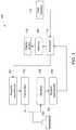
- FIG. 3illustrates an ultrasound image 300 of a body 302 that is generated from image data at a higher resolution.
- the image 300can be a three-dimensional rendered image or a rendered frame of a four-dimensional video formed from higher resolution.
- the body 302is a fetus, but alternatively may be another part of an anatomy or another body.
- the rendered image 300includes several bumps 304 , undulations, and the like, on various surfaces of the body 302 . This is due to the higher resolution of the image data used to form the rendered image 300 revealing more and smaller objects or features of the body 302 , and potentially due to the higher resolution image data having more electronic noise.
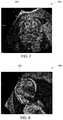
- FIG. 4illustrates another ultrasound rendered image 400 of the same body 302 that is generated from image data at a lower resolution.
- the rendered image 400can be a three-dimensional rendered image or a rendered frame of a four-dimensional video formed from image data at a lower resolution than the image data used to form the rendered image 300 in FIG. 3 .
- the rendered image 400does not include as many bumps 304 , undulations, and the like, on various surfaces of the body 302 , or the bumps 304 , undulations, and the like, do not appear as large in the rendered image 400 when compared with the rendered image 300 . Instead, the surfaces of the body 302 appear smoother than the same surfaces of the same body 302 shown in FIG.
- the surfaces of the body 302appear smoother in FIG. 4 due to the lower resolution of the image data used to form the rendered image 400 revealing fewer objects or features of the body 302 , and potentially due to the lower resolution image data having less electronic noise than the higher resolution image data.
- the processors 116can determine if an operator of the imaging system 100 has provided input via the user interface 115 that requests one or more two-dimensional image slices of the body 302 be formed. Alternatively, the processors 116 can automatically create the two-dimensional image slice(s) as a default action and without operator intervention. If one or more two-dimensional image slices are to be generated, then flow of the method 200 can proceed toward 206 . But, if no two-dimensional image slices are to be generated, then flow of the method 200 can proceed toward 208 .
- the two-dimensional imagesare generated. These images can be generated using the higher resolution image data obtained at 202 .
- the image slicescan be created without reducing or otherwise modifying the resolution of the image data obtained at 202 .
- FIGS. 5, 7, and 9illustrate two-dimensional image slices 500 , 700 , 900 that are generated by the processors 116 using the image data obtained at the higher resolution.
- the image slices 500 , 700 , 900represent images of planes extending through different portions of the imaged body 302 .
- the image slices 500 , 700 , 900can be formed using the image data obtained at 202 .
- the image slices 600 , 800 , 1000represent images of planes extending through different portions of the imaged body 302 .
- the image slices 500 , 600represent image slices of the same plane through the imaged body 302 but generated using different image data resolutions.
- the image slices 700 , 800represent image slices of the same plane through the imaged body 302 but generated using different image data resolutions.
- the image slices 900 , 1000represent image slices of the same plane through the imaged body 302 but generated using different image data resolutions.
- the image slices 500 , 700 , 900are generated from greater image data resolution, while the image slices 600 , 800 , 1000 are generated from smaller image data resolution.
- the image slices 500 , 700 , 900provide sharper, clearer images of the body 302 than the image slices 600 , 800 , 1000 .
- the edges, borders, lines, and the like, of imaged portions of the body 302 in the image slices 500 , 700 , 900are more well-defined and clearer than the same edges, borders, lines, or the like, in the image slices 600 , 800 , 1000 . This is due to the image data used to form the image slices 500 , 700 , 900 being at a higher resolution than the image data used to form the image slices 600 , 800 , 1000 .
- Generating the image slices 500 , 700 , 900 using the higher resolution image datacan provide clearer images to an operator of the imaging system 100 , which can allow for the operator to more easily identify objects within the body 302 . For example, more objects or features may be visible in the higher resolution image slices 500 , 700 , 900 than in the lower resolution image slices 600 , 800 , 1000 .
- the image(s) that are created at 206can be presented on the user interface 115 or on another display device by the processor 116 .
- the processors 116can determine if an operator of the imaging system 100 has provided input via the user interface 115 that requests one or more three- or four-dimensional rendered images or videos of the body 302 be formed. Alternatively, the processors 116 can automatically create the three- or four-dimensional rendered image or videos as a default action and without operator intervention. If one or more three- or four-dimensional rendered images or videos are to be generated, then flow of the method 200 can proceed toward 210 . But, if no three- or four-dimensional rendered images or videos are to be generated, then flow of the method 200 can return toward 204 . Alternatively, the method 200 can terminate or return to another operation.
- a second image data setis created from the originally obtained image data set.
- the second image data set that is createdcan be the same image data obtained at 202 , but with a smaller or lesser acquisition quality level. For example, the higher resolution of the image data obtained at 202 can be reduced to form the second image data set.
- the second image data setcan be created by downsampling the original or first image data set. Downsampling the first image data set can involve reducing the amount of detail or information in the first image data set.
- the second image data setcan be created by calculating averages, medians, modes, or the like, of characteristic values of groups of voxels, pixels, etc., in the first image data set.
- FIG. 11schematically illustrates one example of a first image data set 1100 .
- the first image data set 1100can represent a portion of the image data that is obtained at 202 in the flowchart of the method 200 shown in FIG. 2 .
- the first image data set 1100is formed of several voxels 1102 , which are three-dimensional volumes having characteristics that represent the body 302 that is imaged in a corresponding location. These characteristics can include intensities of the image data, colors of the body 302 , etc.
- a first voxel 1102 representing part of the body 302may have a first color
- a second voxel 1102 representing space around the body 302may have a different, second color to indicate that the first voxel 1102 represents the body 302 and the second voxel 1102 does not represent the body 302 .
- the description of the higher and lower resolution image data setsfocuses on voxels 1102 as forming different parts of each of the image data sets, alternatively, the different image data sets can be described as being formed from two-dimensional pixels or the like.
- the second, reduced resolution image data setcan be formed by calculating representative values of different groups 1104 of the voxels 1102 in the first image data set 1100 , and using these values to represent the different groups 1104 of the voxels 1102 .
- a representative valuecan be calculated for each non-overlapping, mutually exclusive group 1104 of eight voxels 1102 in the first image data set 1100 .
- These groups 1104may be non-overlapping and mutually exclusive in that no two groups 1104 share or include the same voxel 1102 .
- two or more of the groups 1104 of voxels 1102may include the same voxel 1102 .
- each group 1104 of voxels 1102may include a different integer number of voxels 1102 , such as nine voxels 1102 , twenty-seven voxels 1102 , etc.
- each group 1104 of voxels 1102can include a non-integer number of voxels 1102 , such as 3.5 voxels 1102 , 6.5 voxels 1102 , etc.
- the characteristic value for the non-integer group 1104 of voxels 1102can be calculated by sharing voxels 1102 between two or more groups 1104 of voxels 1102 .
- FIG. 12schematically illustrates one example of a second image data set 1200 .
- the second image data set 1200can represent a portion of the image data that is created obtained at 210 in the flowchart of the method 200 shown in FIG. 2 .
- the second image data set 1200is formed of a lesser number of voxels 1202 relative to the first image data set 1100 .
- Individual voxels 1202 in the second image data set 1200may be larger than individual voxels 1102 in the first image data set 1100 .
- each voxel 1202may represent the average, median, mode, or the like, value of the characteristics of a group 1104 of voxels 1102 in the first image data set 1100 .
- individual voxels 1202 in the second image data set 1200may be the same size (or smaller) than the individual voxels 1102 in the first image data set 1100 .
- the average, median, mode, etc. value that is calculated from the voxels 1102 in a group 1104 in the first image data set 1100may be assigned to each of the voxels 1202 in the same sized group of voxels 1202 in the second image data set 1200 .
- the voxel 1202 that is labeled in FIG. 12can represent the average value of the intensities of the voxels 1102 in the group 1104 that is labeled in FIG. 11 .
- an average of the intensity values of the image data associated with the voxels 1102 shown in FIG. 11 in cross-hatchingcan be calculated.
- This average valuecan be assigned to the entire voxel 1202 that is labeled in FIG. 12 .
- Values for other voxels 1202 in the second image data set 1200can be calculated as average values for corresponding groups 1104 of other voxels 1102 . As shown in FIGS.
- downsampling the first image data set 1100 by calculating representative values of the voxels 1102 in different groups 1104 of voxels 1102can reduce the amount of information in the second image data set 1200 . This can reduce the resolution of the second image data set 1200 relative to the first image data set 1100 .
- the second image datacan be created from the first image data in another manner.
- the second image datacan be created by sampling the first image data.
- the second image datacan be formed by taking every n th sample of the first image data, where n is greater than one. This can be achieved by obtaining every second sample of the first image data to form the second image data (e.g., to reduce the resolution in half), every fourth sample of the first image data to form the second image data (e.g., to reduce the resolution by three-quarters), and the like.
- the second image datacan be created by calculating an average of n samples, where n is greater than one.
- the second image datacan be formed from averages or medians of many of the samples of the first image data described above.
- the second image datacan be formed by convoluting the first image data with a kernel filter, such as a lowpass filter kernel.
- a lowpass filter kernelcan be applied to the first image data to form the second image data by averaging values of adjacent voxels or pixels in the first image data, by averaging values of groups of three or more neighboring voxels or pixels in the first image data, or the like.
- the second image datacan be formed by applying one or more non-linear filters to the first image data, such as an anisotropic diffusion filter, another diffusion filter, a bilateral filter, etc.
- a multi-dimensional video or rendered imageis created from the reduced resolution image data set.
- a three-dimensional rendered image or four-dimensional videocan be created from the second data set that is downsampled from the image data set obtained at 202 .
- Creating the three- or four-dimensional rendered image or video from the reduced resolution image datacan provide a clearer or smoother image of the body 302 .
- the image data shown in FIG. 4is created from a reduced resolution image data set (relative to the image data shown in FIG. 3 ).
- the reduced detail or information in the lower resolution image data setcan reduce the presence of bumps, undulations, or other small objects in the rendered image or video (as shown by a comparison of the images shown in FIGS. 3 and 4 ).
- the rendered image(s) or video(s) that are created at 212can be presented on the user interface 115 or on another display device by the processor 116 .
- Flow of the method 200can then terminate, or can return to one or more prior operations. For example, flow of the method 200 can return toward 202 for the acquisition of additional image data.
- the method 200can be used to create three-dimensional models for additive manufacturing instead of or in addition to creating multi-dimensional images or videos.
- the higher resolution image data set obtained at 202can be a scan or imaging of a three-dimensional object, such as a part of a machine.
- the image data setcan be ultrasound image data, or can be image data from another type of imaging modality. This image data set may include too much detail such that creating a three-dimensional printed article from the image data set would include many undesirable bumps, undulations, and the like, and few smooth surfaces. Stated differently, the three-dimensional printed article may appear very different from the original machine part.
- the image data setcan be downsampled to create a reduced resolution image data set at 210 .
- This reduced resolution image data setcan then be used as an input to an additive manufacturing system, such as a three-dimensional printing system.
- This reduced resolution image data setcan be used by the manufacturing or printing system to create the three-dimensional printed article, which will have fewer bumps, undulations, and the like, and may have a shape and appearance that is closer to the original machine part (than the three-dimensional printed article formed from the higher resolution image data set).
- a methodin one embodiment, includes acquiring first ultrasound image data of a body at a first acquisition quality level, generating one or more two-dimensional images of the body using the image data at the first acquisition quality level, and creating second ultrasound image data at a reduced, second acquisition quality level.
- the second ultrasound image datais created from the first ultrasound image data that was acquired at the first acquisition quality level.
- the methodalso includes rendering a multi-dimensional image of the body using the second ultrasound image data at the reduced, second acquisition quality level.
- the first acquisition quality levelis a first spatial resolution of the first ultrasound image data and the second acquisition quality level is a reduced, second spatial resolution of the first ultrasound image data.
- creating the second ultrasound image dataincludes averaging values of one or more of pixels or voxels in the first ultrasound image data.
- creating the second ultrasound image dataincludes reducing a spatial resolution of the first ultrasound image data.
- creating the second ultrasound image dataincludes applying a low-pass kernel filter to the first ultrasound image data.
- rendering the second ultrasound image dataincludes downsampling the first ultrasound image data.
- the second ultrasound image datais obtained without exposing the body to additional ultrasound pulses following acquisition of the first ultrasound image data.
- the multi-dimensional image of the body that is renderedis a three-dimensional image of the body.
- the one or more two-dimensional imagesrepresent two-dimensional slices through the body.
- the first ultrasound image datais three-dimensional ultrasound image data.
- the first ultrasound image datais four-dimensional ultrasound image data.
- the methodalso includes forming a three-dimensional object based on the second ultrasound image data.
- a systemincludes one or more processors configured to receive first ultrasound image data of a body that was obtained at a first acquisition quality level.
- the one or more processorsare configured to generate one or more two-dimensional images of the body using the ultrasound image data at the first acquisition quality level.
- the one or more processorsalso are configured to create second ultrasound image data at a reduced, second acquisition quality level from the first ultrasound image data that was acquired at the first acquisition quality level.
- the one or more processorsalso are configured to render a multi-dimensional image of the body using the second ultrasound image data at the reduced, second acquisition quality level.
- the first acquisition quality levelis a first spatial resolution of the first ultrasound image data and the second acquisition quality level is a reduced, second spatial resolution of the first ultrasound image data.
- the one or more processorsare configured to create the second ultrasound image data by reducing a spatial resolution of the first ultrasound image data.
- the one or more processorsare configured to create the second ultrasound image data by averaging values of one or more of pixels or voxels in the first ultrasound image data.
- the one or more processorsare configured to create the second ultrasound image data by downsampling the first ultrasound image data.
- the one or more processorsare configured to create the second ultrasound image data without the body being exposed to additional ultrasound pulses following acquisition of the first ultrasound image data.
- the second ultrasound image datacan be created using the exact same data that is the first ultrasound image data, or that is at least a portion of the exact same data that is the first ultrasound image data.
- the one or more processorsare configured to render a three-dimensional image of the body as the multi-dimensional image.
- the one or more two-dimensional imagesare two-dimensional slices through the body.
- the first ultrasound image datais three-dimensional ultrasound image data.
- the first ultrasound image datais four-dimensional ultrasound image data.
- a methodincludes acquiring first ultrasound image data of a body at a first spatial resolution, generating two-dimensional image slices of the body using the ultrasound image data at the first spatial resolution, modifying the first ultrasound image data into second ultrasound image data by reducing the first spatial resolution of the first ultrasound image data to a second spatial resolution, and rendering a three-dimensional image of the body using the second ultrasound image data at the reduced, second spatial resolution.
- modifying the first ultrasound image dataincludes averaging values of one or more of pixels or voxels in the first ultrasound image data.
- modifying the first ultrasound image dataincludes downsampling the first ultrasound image data.
- the first ultrasound image datais three-dimensional ultrasound image data or four-dimensional ultrasound image data.
Landscapes
- Engineering & Computer Science (AREA)
- Physics & Mathematics (AREA)
- Health & Medical Sciences (AREA)
- Life Sciences & Earth Sciences (AREA)
- Theoretical Computer Science (AREA)
- General Physics & Mathematics (AREA)
- Nuclear Medicine, Radiotherapy & Molecular Imaging (AREA)
- Radiology & Medical Imaging (AREA)
- General Health & Medical Sciences (AREA)
- Medical Informatics (AREA)
- Computer Graphics (AREA)
- Computer Vision & Pattern Recognition (AREA)
- Surgery (AREA)
- Public Health (AREA)
- Veterinary Medicine (AREA)
- Biomedical Technology (AREA)
- Heart & Thoracic Surgery (AREA)
- Biophysics (AREA)
- Pathology (AREA)
- Animal Behavior & Ethology (AREA)
- Molecular Biology (AREA)
- Geometry (AREA)
- Quality & Reliability (AREA)
- Gynecology & Obstetrics (AREA)
- Pregnancy & Childbirth (AREA)
- Software Systems (AREA)
- Ultra Sonic Daignosis Equipment (AREA)
Abstract
Description
Claims (19)
Priority Applications (2)
| Application Number | Priority Date | Filing Date | Title |
|---|---|---|---|
| US16/019,875US10685439B2 (en) | 2018-06-27 | 2018-06-27 | Imaging system and method providing scalable resolution in multi-dimensional image data |
| CN201910563605.4ACN110717855B (en) | 2018-06-27 | 2019-06-26 | Imaging systems and methods providing scalable resolution in multidimensional image data |
Applications Claiming Priority (1)
| Application Number | Priority Date | Filing Date | Title |
|---|---|---|---|
| US16/019,875US10685439B2 (en) | 2018-06-27 | 2018-06-27 | Imaging system and method providing scalable resolution in multi-dimensional image data |
Publications (2)
| Publication Number | Publication Date |
|---|---|
| US20200005452A1 US20200005452A1 (en) | 2020-01-02 |
| US10685439B2true US10685439B2 (en) | 2020-06-16 |
Family
ID=69008264
Family Applications (1)
| Application Number | Title | Priority Date | Filing Date |
|---|---|---|---|
| US16/019,875Active2038-11-08US10685439B2 (en) | 2018-06-27 | 2018-06-27 | Imaging system and method providing scalable resolution in multi-dimensional image data |
Country Status (2)
| Country | Link |
|---|---|
| US (1) | US10685439B2 (en) |
| CN (1) | CN110717855B (en) |
Families Citing this family (3)
| Publication number | Priority date | Publication date | Assignee | Title |
|---|---|---|---|---|
| US11694415B2 (en) | 2020-10-28 | 2023-07-04 | Autodesk, Inc. | Techniques for training a machine learning model to modify portions of shapes when generating designs for three-dimensional objects |
| US11468634B2 (en)* | 2020-10-28 | 2022-10-11 | Autodesk, Inc. | Machine learning techniques for generating designs for three-dimensional objects |
| US11766239B2 (en)* | 2021-02-26 | 2023-09-26 | GE Precision Healthcare LLC | Ultrasound imaging system and method for low-resolution background volume acquisition |
Citations (53)
| Publication number | Priority date | Publication date | Assignee | Title |
|---|---|---|---|---|
| US5785889A (en)* | 1995-10-06 | 1998-07-28 | Merck Patent Gesellschaft Mit Beschrankter Haftung | Anisotropic polymer |
| US5795296A (en)* | 1996-03-29 | 1998-08-18 | University Of Washington | Pipeline process for automatically measuring object boundary from ultrasound image samples |
| US20010011969A1 (en) | 1999-12-21 | 2001-08-09 | Hans Polz | Process and system for the generation of diagnostic-quality three-dimensional ultrasound image data sets |
| US6530885B1 (en)* | 2000-03-17 | 2003-03-11 | Atl Ultrasound, Inc. | Spatially compounded three dimensional ultrasonic images |
| US20040126007A1 (en)* | 2002-12-31 | 2004-07-01 | Ziel Jonathan Mark | System and method for improved multiple-dimension image displays |
| US20060020207A1 (en) | 2004-07-12 | 2006-01-26 | Siemens Medical Solutions Usa, Inc. | Volume rendering quality adaptations for ultrasound imaging |
| US20060173326A1 (en)* | 2003-06-10 | 2006-08-03 | Koninklijke Philips Electronics N.V. | User interface for a three-dimensional colour ultrasound imaging system |
| US20070167801A1 (en)* | 2005-12-02 | 2007-07-19 | Webler William E | Methods and apparatuses for image guided medical procedures |
| US20080208061A1 (en)* | 2007-02-23 | 2008-08-28 | General Electric Company | Methods and systems for spatial compounding in a handheld ultrasound device |
| US20090112095A1 (en)* | 2005-04-14 | 2009-04-30 | Verasonics, Inc. | Ultrasound imaging system with pixel oriented processing |
| US7664301B2 (en) | 2004-10-18 | 2010-02-16 | Medison Co., Ltd. | Method and apparatus for enhancing image quality of a two-dimensional ultrasound image |
| US20100286518A1 (en)* | 2009-05-11 | 2010-11-11 | General Electric Company | Ultrasound system and method to deliver therapy based on user defined treatment spaces |
| US20100286519A1 (en)* | 2009-05-11 | 2010-11-11 | General Electric Company | Ultrasound system and method to automatically identify and treat adipose tissue |
| US20110055148A1 (en)* | 2009-08-26 | 2011-03-03 | Sevald Berg | System and method for reducing ultrasound information storage requirements |
| US20110255762A1 (en)* | 2010-04-15 | 2011-10-20 | Harald Deischinger | Method and system for determining a region of interest in ultrasound data |
| US20120065499A1 (en)* | 2009-05-20 | 2012-03-15 | Hitachi Medical Corporation | Medical image diagnosis device and region-of-interest setting method therefore |
| US20120108960A1 (en)* | 2010-11-03 | 2012-05-03 | Halmann Menachem Nahi | Method and system for organizing stored ultrasound data |
| US20120116218A1 (en)* | 2010-11-10 | 2012-05-10 | Jennifer Martin | Method and system for displaying ultrasound data |
| US20120245465A1 (en)* | 2011-03-25 | 2012-09-27 | Joger Hansegard | Method and system for displaying intersection information on a volumetric ultrasound image |
| US8280483B2 (en)* | 2006-06-14 | 2012-10-02 | Koninklijke Philips Electronics N.V. | Multi-modality medical image viewing |
| US20130165785A1 (en)* | 2011-12-21 | 2013-06-27 | General Electric Company | Method and apparatus for aperture selection in ultrasound imaging |
| US20130281854A1 (en)* | 2012-04-24 | 2013-10-24 | General Electric Company | Diagnostic system and method for obtaining data relating to a cardiac medical condition |
| US20140044325A1 (en)* | 2012-08-09 | 2014-02-13 | Hologic, Inc. | System and method of overlaying images of different modalities |
| US20140221832A1 (en) | 2013-02-01 | 2014-08-07 | Siemens Medical Solutions Usa, Inc. | Tuning ultrasound acquisition parameters |
| US20140347388A1 (en)* | 2006-05-05 | 2014-11-27 | General Electric Company | User interface and method for identifying related information displayed in an ultrasound system |
| US8976934B2 (en) | 2012-06-19 | 2015-03-10 | General Electric Company | Radiation apertures for X-ray collimators |
| US20150141814A1 (en)* | 2013-11-21 | 2015-05-21 | Samsung Electronics Co., Ltd. | Apparatus and method for processing a medical image of a body lumen |
| US20150164330A1 (en)* | 2013-12-16 | 2015-06-18 | N22 E.U. | Ultrasound imaging system and method for generateing a blended cine loop |
| US9060669B1 (en)* | 2007-12-20 | 2015-06-23 | Zonare Medical Systems, Inc. | System and method for providing variable ultrasound array processing in a post-storage mode |
| US20150238168A1 (en) | 2012-09-13 | 2015-08-27 | Koninklijke Philips N.V. | Mobile 3d wireless ultrasound image acquisition device and ultrasound imaging system |
| US20160015368A1 (en) | 2013-03-07 | 2016-01-21 | Koninklijke Philips N.V. | Multi-purpose ultrasound image acquisition device |
| US20160030008A1 (en)* | 2014-07-30 | 2016-02-04 | General Electric Company | System and method for registering ultrasound information to an x-ray image |
| US20160078623A1 (en) | 2014-09-16 | 2016-03-17 | Esaote S.P.A. | Method and apparatus for acquiring and fusing ultrasound images with pre-acquired images |
| US20160081658A1 (en)* | 2014-09-22 | 2016-03-24 | General Electric Company | Method and system for registering a medical image with a graphical model |
| US20160113632A1 (en) | 2013-05-28 | 2016-04-28 | Universität Bern | Method and system for 3d acquisition of ultrasound images |
| US20160144219A1 (en)* | 2014-11-24 | 2016-05-26 | Larry Koenig | Dual-Handled Selectively Rotating Weight Device and Related Systems and Methods |
| US20160157828A1 (en)* | 2014-06-05 | 2016-06-09 | Chikayoshi Sumi | Beamforming method, measurement and imaging instruments, and communication instruments |
| US20160228091A1 (en)* | 2012-03-26 | 2016-08-11 | Noah Berger | Tablet ultrasound system |
| US20160328998A1 (en)* | 2008-03-17 | 2016-11-10 | Worcester Polytechnic Institute | Virtual interactive system for ultrasound training |
| US20170209125A1 (en)* | 2016-01-22 | 2017-07-27 | General Electric Company | Diagnostic system and method for obtaining measurements from a medical image |
| US20170238907A1 (en)* | 2016-02-22 | 2017-08-24 | General Electric Company | Methods and systems for generating an ultrasound image |
| US20170238904A1 (en)* | 2016-02-19 | 2017-08-24 | General Electric Company | Automatic alignment of ultrasound volumes |
| US20180085043A1 (en)* | 2016-09-26 | 2018-03-29 | General Electric Company | Method and system for measuring a volume of an organ of interest |
| US20180129782A1 (en)* | 2016-11-09 | 2018-05-10 | General Electric Company | System and method for saving medical imaging data |
| US20180206820A1 (en)* | 2017-01-26 | 2018-07-26 | Carestream Health, Inc. | Ultrasound apparatus and method |
| US10402969B2 (en)* | 2017-03-10 | 2019-09-03 | General Electric Company | Methods and systems for model driven multi-modal medical imaging |
| US20190318484A1 (en)* | 2018-04-12 | 2019-10-17 | Veran Medical Technologies, Inc. | Apparatuses and methods for navigation in and local segmentation extension of anatomical treelike structures |
| US10453193B2 (en)* | 2017-05-05 | 2019-10-22 | General Electric Company | Methods and system for shading a two-dimensional ultrasound image |
| US20190325620A1 (en)* | 2018-04-23 | 2019-10-24 | Elekta Ab (Publ) | Posterior image sampling using statistical learning model |
| US20190332900A1 (en)* | 2018-04-30 | 2019-10-31 | Elekta Ab | Modality-agnostic method for medical image representation |
| US20190350659A1 (en)* | 2016-12-08 | 2019-11-21 | Intuitive Surgical Operations, Inc, | Systems and methods for navigation in image-guided medical procedures |
| US20190388060A1 (en)* | 2018-06-22 | 2019-12-26 | General Electric Company | Imaging system and method with live examination completeness monitor |
| US20190392944A1 (en)* | 2018-06-22 | 2019-12-26 | General Electric Company | Method and workstations for a diagnostic support system |
Family Cites Families (16)
| Publication number | Priority date | Publication date | Assignee | Title |
|---|---|---|---|---|
| JP4864554B2 (en)* | 2006-06-12 | 2012-02-01 | 株式会社東芝 | Ultrasonic diagnostic apparatus, medical image processing apparatus, and medical image processing program |
| US8073211B2 (en)* | 2007-02-23 | 2011-12-06 | General Electric Company | Method and apparatus for generating variable resolution medical images |
| KR101182891B1 (en)* | 2009-12-09 | 2012-09-13 | 삼성메디슨 주식회사 | Ultrasound system and method for providing compounding image of two-dimensional ultrasound image and three-dimensional ultrasound image |
| US10835207B2 (en)* | 2009-12-23 | 2020-11-17 | Biosense Webster (Israel) Ltd. | Fast anatomical mapping using ultrasound images |
| US8708914B2 (en)* | 2010-06-07 | 2014-04-29 | Atheropoint, LLC | Validation embedded segmentation method for vascular ultrasound images |
| US20120157844A1 (en)* | 2010-12-16 | 2012-06-21 | General Electric Company | System and method to illustrate ultrasound data at independent displays |
| US9324184B2 (en)* | 2011-12-14 | 2016-04-26 | Microsoft Technology Licensing, Llc | Image three-dimensional (3D) modeling |
| CN103845081B (en)* | 2012-11-28 | 2018-04-10 | 深圳迈瑞生物医疗电子股份有限公司 | Ultrasonic elastograph imaging system and method, real-time dynamic interframe processing method |
| JP5631453B2 (en)* | 2013-07-05 | 2014-11-26 | キヤノン株式会社 | Image processing apparatus and image processing method |
| US20150257735A1 (en)* | 2013-10-24 | 2015-09-17 | Evena Medical, Inc. | Systems and methods for displaying medical images |
| CN103761705B (en)* | 2014-01-10 | 2017-01-04 | 北京东方惠尔图像技术有限公司 | Ultrasonic image magnifying method and device |
| CN106794007B (en)* | 2014-08-18 | 2021-03-09 | 毛伊图像公司 | Network-based ultrasound imaging system |
| US10905396B2 (en)* | 2014-11-18 | 2021-02-02 | C. R. Bard, Inc. | Ultrasound imaging system having automatic image presentation |
| KR102551252B1 (en)* | 2015-11-11 | 2023-07-05 | 삼성메디슨 주식회사 | Ultrasonic diagnostic apparatus and operating method for the same |
| CN105428484B (en)* | 2015-11-12 | 2019-05-03 | 西安交通大学 | A kind of lens shape patterned sapphire substrate and preparation method thereof |
| US10835212B2 (en)* | 2016-04-01 | 2020-11-17 | Canon Medical Systems Corporation | Medical image processing apparatus |
- 2018
- 2018-06-27USUS16/019,875patent/US10685439B2/enactiveActive
- 2019
- 2019-06-26CNCN201910563605.4Apatent/CN110717855B/enactiveActive
Patent Citations (56)
| Publication number | Priority date | Publication date | Assignee | Title |
|---|---|---|---|---|
| US5785889A (en)* | 1995-10-06 | 1998-07-28 | Merck Patent Gesellschaft Mit Beschrankter Haftung | Anisotropic polymer |
| US5795296A (en)* | 1996-03-29 | 1998-08-18 | University Of Washington | Pipeline process for automatically measuring object boundary from ultrasound image samples |
| US20010011969A1 (en) | 1999-12-21 | 2001-08-09 | Hans Polz | Process and system for the generation of diagnostic-quality three-dimensional ultrasound image data sets |
| US6530885B1 (en)* | 2000-03-17 | 2003-03-11 | Atl Ultrasound, Inc. | Spatially compounded three dimensional ultrasonic images |
| US20040126007A1 (en)* | 2002-12-31 | 2004-07-01 | Ziel Jonathan Mark | System and method for improved multiple-dimension image displays |
| US20060173326A1 (en)* | 2003-06-10 | 2006-08-03 | Koninklijke Philips Electronics N.V. | User interface for a three-dimensional colour ultrasound imaging system |
| US20060020207A1 (en) | 2004-07-12 | 2006-01-26 | Siemens Medical Solutions Usa, Inc. | Volume rendering quality adaptations for ultrasound imaging |
| US7601121B2 (en) | 2004-07-12 | 2009-10-13 | Siemens Medical Solutions Usa, Inc. | Volume rendering quality adaptations for ultrasound imaging |
| US7664301B2 (en) | 2004-10-18 | 2010-02-16 | Medison Co., Ltd. | Method and apparatus for enhancing image quality of a two-dimensional ultrasound image |
| US20090112095A1 (en)* | 2005-04-14 | 2009-04-30 | Verasonics, Inc. | Ultrasound imaging system with pixel oriented processing |
| US20070167801A1 (en)* | 2005-12-02 | 2007-07-19 | Webler William E | Methods and apparatuses for image guided medical procedures |
| US20140347388A1 (en)* | 2006-05-05 | 2014-11-27 | General Electric Company | User interface and method for identifying related information displayed in an ultrasound system |
| US8280483B2 (en)* | 2006-06-14 | 2012-10-02 | Koninklijke Philips Electronics N.V. | Multi-modality medical image viewing |
| US20080208061A1 (en)* | 2007-02-23 | 2008-08-28 | General Electric Company | Methods and systems for spatial compounding in a handheld ultrasound device |
| US9060669B1 (en)* | 2007-12-20 | 2015-06-23 | Zonare Medical Systems, Inc. | System and method for providing variable ultrasound array processing in a post-storage mode |
| US20160328998A1 (en)* | 2008-03-17 | 2016-11-10 | Worcester Polytechnic Institute | Virtual interactive system for ultrasound training |
| US20100286519A1 (en)* | 2009-05-11 | 2010-11-11 | General Electric Company | Ultrasound system and method to automatically identify and treat adipose tissue |
| US20100286518A1 (en)* | 2009-05-11 | 2010-11-11 | General Electric Company | Ultrasound system and method to deliver therapy based on user defined treatment spaces |
| US20120065499A1 (en)* | 2009-05-20 | 2012-03-15 | Hitachi Medical Corporation | Medical image diagnosis device and region-of-interest setting method therefore |
| US20110055148A1 (en)* | 2009-08-26 | 2011-03-03 | Sevald Berg | System and method for reducing ultrasound information storage requirements |
| US20110255762A1 (en)* | 2010-04-15 | 2011-10-20 | Harald Deischinger | Method and system for determining a region of interest in ultrasound data |
| US20120108960A1 (en)* | 2010-11-03 | 2012-05-03 | Halmann Menachem Nahi | Method and system for organizing stored ultrasound data |
| US20120116218A1 (en)* | 2010-11-10 | 2012-05-10 | Jennifer Martin | Method and system for displaying ultrasound data |
| US20120245465A1 (en)* | 2011-03-25 | 2012-09-27 | Joger Hansegard | Method and system for displaying intersection information on a volumetric ultrasound image |
| US20130165785A1 (en)* | 2011-12-21 | 2013-06-27 | General Electric Company | Method and apparatus for aperture selection in ultrasound imaging |
| US20160228091A1 (en)* | 2012-03-26 | 2016-08-11 | Noah Berger | Tablet ultrasound system |
| US20130281854A1 (en)* | 2012-04-24 | 2013-10-24 | General Electric Company | Diagnostic system and method for obtaining data relating to a cardiac medical condition |
| US8976934B2 (en) | 2012-06-19 | 2015-03-10 | General Electric Company | Radiation apertures for X-ray collimators |
| US20140044325A1 (en)* | 2012-08-09 | 2014-02-13 | Hologic, Inc. | System and method of overlaying images of different modalities |
| US20150238168A1 (en) | 2012-09-13 | 2015-08-27 | Koninklijke Philips N.V. | Mobile 3d wireless ultrasound image acquisition device and ultrasound imaging system |
| US9918700B2 (en) | 2013-02-01 | 2018-03-20 | Siemens Medical Solutions Usa, Inc. | Tuning ultrasound acquisition parameters |
| US20140221832A1 (en) | 2013-02-01 | 2014-08-07 | Siemens Medical Solutions Usa, Inc. | Tuning ultrasound acquisition parameters |
| US20160015368A1 (en) | 2013-03-07 | 2016-01-21 | Koninklijke Philips N.V. | Multi-purpose ultrasound image acquisition device |
| US20160113632A1 (en) | 2013-05-28 | 2016-04-28 | Universität Bern | Method and system for 3d acquisition of ultrasound images |
| US20150141814A1 (en)* | 2013-11-21 | 2015-05-21 | Samsung Electronics Co., Ltd. | Apparatus and method for processing a medical image of a body lumen |
| US20150164330A1 (en)* | 2013-12-16 | 2015-06-18 | N22 E.U. | Ultrasound imaging system and method for generateing a blended cine loop |
| US20160157828A1 (en)* | 2014-06-05 | 2016-06-09 | Chikayoshi Sumi | Beamforming method, measurement and imaging instruments, and communication instruments |
| US20160030008A1 (en)* | 2014-07-30 | 2016-02-04 | General Electric Company | System and method for registering ultrasound information to an x-ray image |
| US20160078623A1 (en) | 2014-09-16 | 2016-03-17 | Esaote S.P.A. | Method and apparatus for acquiring and fusing ultrasound images with pre-acquired images |
| US20160081658A1 (en)* | 2014-09-22 | 2016-03-24 | General Electric Company | Method and system for registering a medical image with a graphical model |
| US20160144219A1 (en)* | 2014-11-24 | 2016-05-26 | Larry Koenig | Dual-Handled Selectively Rotating Weight Device and Related Systems and Methods |
| US20170209125A1 (en)* | 2016-01-22 | 2017-07-27 | General Electric Company | Diagnostic system and method for obtaining measurements from a medical image |
| US20170238904A1 (en)* | 2016-02-19 | 2017-08-24 | General Electric Company | Automatic alignment of ultrasound volumes |
| US20170238907A1 (en)* | 2016-02-22 | 2017-08-24 | General Electric Company | Methods and systems for generating an ultrasound image |
| US20180085043A1 (en)* | 2016-09-26 | 2018-03-29 | General Electric Company | Method and system for measuring a volume of an organ of interest |
| US20180129782A1 (en)* | 2016-11-09 | 2018-05-10 | General Electric Company | System and method for saving medical imaging data |
| US20190350659A1 (en)* | 2016-12-08 | 2019-11-21 | Intuitive Surgical Operations, Inc, | Systems and methods for navigation in image-guided medical procedures |
| US20180206820A1 (en)* | 2017-01-26 | 2018-07-26 | Carestream Health, Inc. | Ultrasound apparatus and method |
| US10402969B2 (en)* | 2017-03-10 | 2019-09-03 | General Electric Company | Methods and systems for model driven multi-modal medical imaging |
| US10453193B2 (en)* | 2017-05-05 | 2019-10-22 | General Electric Company | Methods and system for shading a two-dimensional ultrasound image |
| US20190380685A1 (en)* | 2017-05-05 | 2019-12-19 | General Electric Company | Methods and system for shading a two-dimensional ultrasound image |
| US20190318484A1 (en)* | 2018-04-12 | 2019-10-17 | Veran Medical Technologies, Inc. | Apparatuses and methods for navigation in and local segmentation extension of anatomical treelike structures |
| US20190325620A1 (en)* | 2018-04-23 | 2019-10-24 | Elekta Ab (Publ) | Posterior image sampling using statistical learning model |
| US20190332900A1 (en)* | 2018-04-30 | 2019-10-31 | Elekta Ab | Modality-agnostic method for medical image representation |
| US20190388060A1 (en)* | 2018-06-22 | 2019-12-26 | General Electric Company | Imaging system and method with live examination completeness monitor |
| US20190392944A1 (en)* | 2018-06-22 | 2019-12-26 | General Electric Company | Method and workstations for a diagnostic support system |
Also Published As
| Publication number | Publication date |
|---|---|
| CN110717855B (en) | 2023-11-03 |
| US20200005452A1 (en) | 2020-01-02 |
| CN110717855A (en) | 2020-01-21 |
Similar Documents
| Publication | Publication Date | Title |
|---|---|---|
| US11238562B2 (en) | Ultrasound system with deep learning network for image artifact identification and removal | |
| JP7077118B2 (en) | Methods and systems for shading 2D ultrasound images | |
| CN102436672B (en) | Ultrasonic image processing apparatus | |
| US9513368B2 (en) | Method and system for ultrasound data processing | |
| EP3905960B1 (en) | Systems and methods for contrast enhanced imaging | |
| US9392995B2 (en) | Ultrasound imaging system and method | |
| US10499879B2 (en) | Systems and methods for displaying intersections on ultrasound images | |
| CN106600550B (en) | Ultrasonic image processing method and system | |
| US9366754B2 (en) | Ultrasound imaging system and method | |
| US20120288172A1 (en) | Method and system for ultrasound imaging with cross-plane images | |
| US8900147B2 (en) | Performing image process and size measurement upon a three-dimensional ultrasound image in an ultrasound system | |
| US20120154400A1 (en) | Method of reducing noise in a volume-rendered image | |
| US20110137168A1 (en) | Providing a three-dimensional ultrasound image based on a sub region of interest in an ultrasound system | |
| US10685439B2 (en) | Imaging system and method providing scalable resolution in multi-dimensional image data | |
| US8727990B2 (en) | Providing an ultrasound spatial compound image in an ultrasound system | |
| US20100113931A1 (en) | Ultrasound System And Method For Providing Three-Dimensional Ultrasound Images | |
| US10564272B2 (en) | Display of imaging data in a moving viewport | |
| CN116831625A (en) | Ultrasonic imaging method and equipment | |
| US20140276045A1 (en) | Method and apparatus for processing ultrasound data using scan line information | |
| US20180214128A1 (en) | Method and ultrasound imaging system for representing ultrasound data acquired with different imaging modes | |
| US20240153048A1 (en) | Artifact removal in ultrasound images |
Legal Events
| Date | Code | Title | Description |
|---|---|---|---|
| AS | Assignment | Owner name:GENERAL ELECTRIC COMPANY, NEW YORK Free format text:ASSIGNMENT OF ASSIGNORS INTEREST;ASSIGNORS:SCHROECKER, GERALD;BRANDL, HELMUT;FOSODEDER, ERWIN;REEL/FRAME:046213/0475 Effective date:20180626 | |
| FEPP | Fee payment procedure | Free format text:ENTITY STATUS SET TO UNDISCOUNTED (ORIGINAL EVENT CODE: BIG.); ENTITY STATUS OF PATENT OWNER: LARGE ENTITY | |
| STPP | Information on status: patent application and granting procedure in general | Free format text:NON FINAL ACTION MAILED | |
| STPP | Information on status: patent application and granting procedure in general | Free format text:FINAL REJECTION MAILED | |
| STPP | Information on status: patent application and granting procedure in general | Free format text:PUBLICATIONS -- ISSUE FEE PAYMENT VERIFIED | |
| STCF | Information on status: patent grant | Free format text:PATENTED CASE | |
| MAFP | Maintenance fee payment | Free format text:PAYMENT OF MAINTENANCE FEE, 4TH YEAR, LARGE ENTITY (ORIGINAL EVENT CODE: M1551); ENTITY STATUS OF PATENT OWNER: LARGE ENTITY Year of fee payment:4 | |
| AS | Assignment | Owner name:GE PRECISION HEALTHCARE LLC, WISCONSIN Free format text:NUNC PRO TUNC ASSIGNMENT;ASSIGNOR:GENERAL ELECTRIC COMPANY;REEL/FRAME:071225/0218 Effective date:20250505 |