US10684476B2 - Head-wearable ultra-wide field of view display device - Google Patents
Head-wearable ultra-wide field of view display deviceDownload PDFInfo
- Publication number
- US10684476B2 US10684476B2US14/884,975US201514884975AUS10684476B2US 10684476 B2US10684476 B2US 10684476B2US 201514884975 AUS201514884975 AUS 201514884975AUS 10684476 B2US10684476 B2US 10684476B2
- Authority
- US
- United States
- Prior art keywords
- light
- reflective surface
- uwfov
- light source
- diverging
- Prior art date
- Legal status (The legal status is an assumption and is not a legal conclusion. Google has not performed a legal analysis and makes no representation as to the accuracy of the status listed.)
- Active, expires
Links
Images


Classifications
- G—PHYSICS
- G02—OPTICS
- G02B—OPTICAL ELEMENTS, SYSTEMS OR APPARATUS
- G02B27/00—Optical systems or apparatus not provided for by any of the groups G02B1/00 - G02B26/00, G02B30/00
- G02B27/01—Head-up displays
- G02B27/017—Head mounted
- G02B27/0172—Head mounted characterised by optical features
- G—PHYSICS
- G02—OPTICS
- G02B—OPTICAL ELEMENTS, SYSTEMS OR APPARATUS
- G02B17/00—Systems with reflecting surfaces, with or without refracting elements
- G02B17/02—Catoptric systems, e.g. image erecting and reversing system
- G02B17/06—Catoptric systems, e.g. image erecting and reversing system using mirrors only, i.e. having only one curved mirror
- G02B17/0605—Catoptric systems, e.g. image erecting and reversing system using mirrors only, i.e. having only one curved mirror using two curved mirrors
- G02B17/0621—Catoptric systems, e.g. image erecting and reversing system using mirrors only, i.e. having only one curved mirror using two curved mirrors off-axis or unobscured systems in which not all of the mirrors share a common axis of rotational symmetry, e.g. at least one of the mirrors is warped, tilted or decentered with respect to the other elements
- G—PHYSICS
- G02—OPTICS
- G02B—OPTICAL ELEMENTS, SYSTEMS OR APPARATUS
- G02B27/00—Optical systems or apparatus not provided for by any of the groups G02B1/00 - G02B26/00, G02B30/00
- G02B27/01—Head-up displays
- G02B27/0101—Head-up displays characterised by optical features
- G02B2027/0123—Head-up displays characterised by optical features comprising devices increasing the field of view
- G—PHYSICS
- G02—OPTICS
- G02B—OPTICAL ELEMENTS, SYSTEMS OR APPARATUS
- G02B27/00—Optical systems or apparatus not provided for by any of the groups G02B1/00 - G02B26/00, G02B30/00
- G02B27/01—Head-up displays
- G02B27/0101—Head-up displays characterised by optical features
- G02B2027/013—Head-up displays characterised by optical features comprising a combiner of particular shape, e.g. curvature
- G—PHYSICS
- G02—OPTICS
- G02B—OPTICAL ELEMENTS, SYSTEMS OR APPARATUS
- G02B27/00—Optical systems or apparatus not provided for by any of the groups G02B1/00 - G02B26/00, G02B30/00
- G02B27/01—Head-up displays
- G02B27/0101—Head-up displays characterised by optical features
- G02B2027/0132—Head-up displays characterised by optical features comprising binocular systems
- G—PHYSICS
- G02—OPTICS
- G02B—OPTICAL ELEMENTS, SYSTEMS OR APPARATUS
- G02B27/00—Optical systems or apparatus not provided for by any of the groups G02B1/00 - G02B26/00, G02B30/00
- G02B27/01—Head-up displays
- G02B27/017—Head mounted
- G02B2027/0178—Eyeglass type
Definitions
- the embodimentsrelate to head-wearable display devices and, in particular, to head-wearable display devices with multiple reflective surfaces that have an ultra-wide field of view and utilize a narrow-beam light source, such as a Liquid Crystal on Silicon display light source.
- a narrow-beam light sourcesuch as a Liquid Crystal on Silicon display light source.
- a Liquid Crystal on Silicon (LCoS) displayoffers a relatively bright, high-resolution display, and thus would be a desirable source of light for an ultra-wide field of view (UWFOV) reflective surface.
- narrow-beam displayssuch as an LCoS display, emit light in a relatively narrow +/ ⁇ 10-degree cone. The narrowness of the beam makes it difficult or impracticable to use an LCoS display in conjunction with a UWFOV reflective surface, such as a 130-degree UWFOV reflective surface. Placing a lens in front of the narrow-beam display may diverge the light, but may not make the light field wide enough to support the parameters of a UWFOV reflective surface.
- the curvature of the UWFOV reflective surfacereflects the pixels of the narrow-beam display from particular points on the reflector, the resulting reflector power may be too high, resulting in the light focusing inside of an eye instead of at the fovea of the eye.
- the embodimentsrelate to head-wearable display devices and, in particular, to head-wearable display devices that have an ultra-wide field of view (UWFOV) and utilize a narrow-beam light source, such as a Liquid Crystal on Silicon (LCoS) display, a digital light processing (DLP) display, or a laser display.
- the head-wearable display deviceincludes a frame, a narrow-beam light source fixed with respect to the frame, a UWFOV reflective surface fixed with respect to the frame, and a diverging reflective surface fixed with respect to the frame that is configured to receive light emitted from the narrow-beam light source and reflect the light toward the UWFOV reflective surface to spread the light across the UWFOV reflective surface.
- the narrow-beam light sourcecomprises one of an LCoS display, a DLP display, and a laser display.
- the head-wearable display deviceincludes a diverging lens fixed with respect to the narrow-beam light source that is configured to receive the light emitted from the narrow-beam light source and transmit the light toward the diverging reflective surface.
- the UWFOV reflective surfacehas a field of view (FOV) greater than about 100 degrees. In another embodiment, the UWFOV reflective surface has an FOV greater than about 120 degrees, and in yet another embodiment, the UWFOV reflective surface has an FOV greater than about 140 degrees. In one embodiment, the UWFOV reflective surface is configured to substantially collimate the light. In some embodiments, the UWFOV reflective surface converges the light in order to substantially collimate the light.
- FOVfield of view
- a method for presenting an image to an eyecomprising imagery is emitted from a narrow-beam light source.
- the imagerymay comprise video stream imagery or a static image.
- a diverging reflective surfacereflects the light toward a UWFOV reflective surface.
- the UWFOV reflective surfacereflects the light toward the eye.
- FIG. 1is a diagram of a head-wearable ultra-wide field of view (UWFOV) display device according to one embodiment
- FIG. 2is a flowchart of a method for presenting an image to an eye according to one embodiment
- FIG. 3is a diagram illustrating the mapping of a narrow-beam light source to a diverging reflective surface and a UWFOV reflective surface according to one embodiment
- FIG. 4is a perspective view of a user utilizing the head-wearable UWFOV display device according to another embodiment
- FIG. 5is a diagram illustrating diverging light rays being reflected into an eye with zero diopters of vergence according to one embodiment.
- FIG. 6is a diagram illustrating an example calculation for determining a radius of curvature of a surface element of the UWFOV reflective surface to reflect and collimate light from such surface element toward a predetermined location of an eye according to one embodiment.
- the embodimentsrelate to head-wearable display devices and, in particular, to head-wearable display devices that have an ultra-wide field of view (UWFOV) and utilize a narrow-beam light source, such as a Liquid Crystal on Silicon (LCoS) display, a digital light processing (DLP) display, and a laser display.
- UWFOVultra-wide field of view
- the embodimentsare particularly applicable to UWFOV reflective surfaces, such as those disclosed in U.S. Pat. Nos. 8,625,200 and 8,781,794, the disclosures of which are incorporated by reference herein.
- the UWFOV reflective surfaces discussed hereintypically, but not necessarily, have a 100-degree or greater field of view (FOV) for each eye of a user and a combined 180-degree FOV for both eyes of the user.
- FOVfield of view
- the embodimentsmay utilize a non-rotationally symmetric, aspherical design due to the rectangular form of a display, and a near-to-the-eye afocal light field.
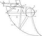
- FIG. 1is a diagram of a head-wearable UWFOV display device 10 (hereinafter “UWFOV display device 10 ” for purposes of brevity) according to one embodiment.
- the UWFOV display device 10includes a frame 12 that has a form factor similar to a pair of glasses, and a user 14 wears the UWFOV display device 10 similarly to how the user 14 would wear a pair of glasses.
- the embodimentsare not limited to any particular form factor and may comprise any form factor capable of holding the various components with respect to one another, and with respect to eyes 16 (only one illustrated) of the user 14 .
- the UWFOV display device 10may be coupled to a head 18 of the user 14 via straps.
- the UWFOV display device 10may be coupled to an apparatus that is worn on the head 18 , such as a hat, or a helmet.
- a UWFOV reflective surface 20is fixed with respect to the frame 12 .
- the UWFOV reflective surface 20may be substantially similar or identical to the reflective surfaces disclosed in U.S. Pat. Nos. 8,625,200 and/or 8,781,794.
- the UWFOV reflective surface 20may, for example, have a 100-degree or greater horizontal FOV for each eye 16 of the user 14 ; a 120-degree or greater horizontal FOV for each eye 16 of the user 14 ; or a 135-degree or greater horizontal FOV for each eye 16 of the user 14 .
- a narrow-beam light source 22is fixed with respect to the frame 12 .
- the narrow-beam light source 22may comprise any suitable narrow-beam display or microdisplay, such as, for example, an LCoS display, a DLP display, or a laser display.
- the microdisplayhas a 4096 ⁇ 2240 pixel resolution and an area of 18.43 mm by 10.08 mm.
- the narrow-beam light source 22may comprise a diagonal dimension of less than one inch, such as, by way of non-limiting example, 0.7 inches, and may emit light in a relatively narrow cone, such as a +/ ⁇ 10-degree cone.
- the narrow-beam light source 22is mapped to the UWFOV reflective surface 20 .
- the narrow-beam light source 22comprises a display panel that has a plurality of pixels at a particular resolution, and the pixels are mapped to corresponding locations on the UWFOV reflective surface 20 .
- Each location on the UWFOV reflective surface 20is configured to reflect and collimate light emitted by the corresponding pixels toward the eye 16 of the user 14 .
- the UWFOV reflective surface 20is engineered such that light received from pixels of the narrow-beam light source 22 other than the particular corresponding pixels is reflected in a direction other than the eyes 16 of the user 14 .
- the UWFOV display device 10includes a diverging reflective surface 24 that is fixed with respect to the frame 12 .
- the diverging reflective surface 24is configured to receive light emitted from the narrow-beam light source 22 and reflect the light toward the UWFOV reflective surface 20 to spread the light completely across the UWFOV reflective surface 20 .
- the UWFOV reflective surface 20receives the light from the diverging reflective surface 24 and reflects those light rays that are emitted by the corresponding pixels of the narrow-beam light source 22 toward the eye 16 of the user 14 .
- the UWFOV reflective surface 20is configured to substantially collimate the light. While for purposes of illustration only the right eye 16 of the user 14 is shown in FIG. 1 , the elements illustrated in FIG.
- the UWFOV display device 10may contain a pair of narrow-beam light sources 22 , a pair of diverging reflective surfaces 24 , and a pair of UWFOV reflective surfaces 20 .
- FIG. 2is a flowchart of a method for presenting an image to the eye 16 according to one embodiment.
- FIG. 2will be discussed in conjunction with FIG. 1 .
- the narrow-beam light source 22emits light that comprises imagery ( FIG. 2 , block 100 ).
- the videomay comprise imagery depicting a virtual environment, or the imagery may comprise one or more virtual objects that may be presented to the eye 16 positioned with respect to real-world imagery that the eye 16 concurrently views, such as in an augmented reality embodiment.
- the diverging reflective surface 24reflects the light toward the UWFOV reflective surface 20 ( FIG. 2 , block 102 ).
- the UWFOV reflective surface 20reflects the light toward the eye 16 ( FIG. 2 , block 104 ).
- the UWFOV reflective surface 20is a non-rotationally symmetric surface and, in some embodiments, is a concave surface, that is mapped to the narrow-beam light source 22 .
- Such mappingmay be implemented as disclosed herein as well as in conjunction, for example, with mechanisms disclosed in U.S. Pat. No. 8,781,794 (hereinafter the '794 Patent).
- non-symmetrical lens surfacessuch as the UWFOV reflective surface 20
- the UWFOV reflective surface 20comprises a plurality of different surface elements oriented to reflect and collimate light from corresponding regions of the narrow-beam light source 22 toward the predetermined location of the eye 16 .
- the UWFOV reflective surface 20comprises multiple, such as thousands, of different surface elements that are mapped to corresponding regions of the narrow-beam light source 22 .
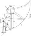
- FIG. 3is a diagram illustrating the mapping of the narrow-beam light source 22 to the diverging reflective surface 24 and the UWFOV reflective surface 20 according to one embodiment.
- surface elements of the narrow-beam light source 22are mapped to surface elements of the diverging reflective surface 24 and to surface elements of the UWFOV reflective surface 20 .
- a surface elementmay comprise a pixel, or a group of pixels.
- surface elementscorrespond to areas of the respective surfaces.
- the mappingis such that light from a particular surface element of the narrow-beam light source 22 is reflected by a corresponding surface element of the diverging reflective surface 24 to a corresponding surface element of the UWFOV reflective surface 20 .
- the corresponding surface element of the UWFOV reflective surface 20collimates the light and reflects the light toward a predetermined location 26 of the eye 16 .
- Each of the narrow-beam light source 22 , the diverging reflective surface 24 , and the UWFOV reflective surface 20may have the same number of surface elements.
- An example of the mapping of surface elements among the narrow-beam light source 22 , the diverging reflective surface 24 , and the UWFOV reflective surface 20will now be discussed.
- surface elements of the narrow-beam light source 22comprise pixels.
- the diverging reflective surface 24may have a spheroidal shape of a particular radius.
- a line 28is positioned between a pixel 30 of the narrow-beam light source 22 and a selected surface element 32 of the diverging reflective surface 24 .
- a tangent 34 of the slope of the selected surface element 32exists at the selected surface element 32 .
- a three-dimensional (3D) normal 36 of the tangent 34is adjusted so that the 3D normal 36 bisects the angle formed by the line 28 and a line 38 between the selected surface element 32 and a selected surface element 40 on the UWFOV reflective surface 20 .
- This adjustmentidentifies a final tangent 34 of the selected surface element 32 of the diverging reflective surface 24 , and thus the slope of the selected surface element 32 , and thus, the diverging reflective surface 24 may ultimately become non-spheroidal.
- a 3D normal 42 at the selected surface element 40is adjusted to bisect the angle formed by the line 38 and a line 44 from the selected surface element 40 to the predetermined location 26 of the eye 16 .
- the slope of the selected surface element 40is determined. This process may be repeated for each surface element of the narrow-beam light source 22 across the entire FOV to define the overall surfaces of the diverging reflective surface 24 and the UWFOV reflective surface 20 . The process is iterative and may be repeated hundreds of thousands of times to define the diverging reflective surface 24 and the UWFOV reflective surface 20 with as little error as possible. During the iterations, adjustments may be made to the slopes to minimize the overall error of the system.
- Each surface element of the UWFOV reflective surface 20also collimates, or substantially collimates, the light received from the corresponding surface element of the diverging reflective surface 24 , and thus also includes the collimation power in the objective for the multi-objective adaptation process that occurs to create the surfaces of the diverging reflective surface 24 and the UWFOV reflective surface 20 .
- the systemproduces a point cloud representing the UWFOV reflective surface 20 .
- the point cloudmay comprise 500 ⁇ 300 points situated along the UWFOV reflective surface 20 in three dimensions.
- This point cloudmay be imported into a 3D computer-aided design (CAD) system, such as, by way of non-limiting example, Creo.
- CADcomputer-aided design
- CreoCreo
- the 3D CAD systemmay then connect all the points in the point cloud with a non-uniform rational basis spline.
- the connected pointsmay then be tested in an optics test program, or converted into a physical lens with 3D printing or injection molding.
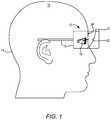
- FIG. 4is a perspective view of the user 14 utilizing a multiple-reflector UWFOV display device 10 - 1 according to another embodiment.
- the UWFOV display device 10 - 1is substantially similar to the UWFOV display device 10 discussed above except as otherwise discussed herein.
- the UWFOV display device 10 - 1includes a diverging lens 45 that is fixed with respect to the narrow-beam light source 22 and that is configured to receive the light emitted by the narrow-beam light source 22 and transmit the light toward the diverging reflective surface 24 .
- the diverging lens 45spreads the light across the diverging reflective surface 24 .
- the diverging lens 45may be fixed to the frame 12 , the narrow-beam light source 22 , or the diverging reflective surface 24 .
- the diverging lens 45is an achromatic lens to help avoid the separation of red, green, and blue components of the light beam.
- FIG. 5is a diagram illustrating diverging light rays 46 being reflected into an eye 16 with zero diopters of vergence according to one embodiment.
- the light rays 46are emitted from a location 48 of the narrow-beam light source 22 and travel in an optical path to enter a pupil 50 of the eye 16 and form a centric 52 at the retina or fovea.
- the cone defined by the pupil 50 and the centric 52 at the retina or foveais based on a pencil of light 54 that is reflected from the UWFOV reflective surface 20 after being diverged by the diverging reflective surface 24 .
- the ability to collimate the light rays 46 to the eye 16is provided in part by the distance D 1 between the narrow-beam light source 22 and the diverging reflective surface 24 , the distance D 2 between the diverging reflective surface 24 and the UWFOV reflective surface 20 , and the distance D 3 between the UWFOV reflective surface 20 and the eye 16 .
- the UWFOV display device 10is a near-to-the-eye system and the distance from the narrow-beam light source 22 to the eye 16 is substantially shorter than, for example, distances utilized in a telescope system, the vergence, or diopter, of light emitted from the narrow-beam light source 22 changes rapidly throughout the UWFOV display device 10 .
- pixels of the narrow-beam light source 22are mapped to corresponding locations on the UWFOV reflective surface 20 , and the locations on the UWFOV reflective surface 20 are configured to reflect and collimate light emitted by the corresponding pixels toward the eye 16 .
- the light rays 46are reflected by the diverging reflective surface 24 toward the UWFOV reflective surface 20 .
- the location 58 of the UWFOV reflective surface 20is configured to collimate the light rays 46 that originate from the location 48 of the narrow-beam light source 22 to bring the vergence of the light rays 46 to 0D, such that collimated light rays 46 are reflected toward the eye 16 . If a lens is positioned between the narrow-beam light source 22 and the diverging reflective surface 24 , the vergence of the light rays 46 will be further modified.
- the UWFOV display device 10produces a wide FOV by angling the reflecting points along the UWFOV reflective surface 20 to reflect the light from the correct pixels of the narrow-beam light source 22 , which introduces a further constraint on the bending of the light rays 46 , which is a function of the display width and the expected FOV.
- FIG. 6is a diagram illustrating an example calculation for determining a radius of curvature of a surface element of the UWFOV reflective surface 20 to reflect and collimate light from such surface element toward the predetermined location 26 of the eye 16 according to one embodiment. Assume that a light ray 60 is emitted from the narrow-beam light source 22 . Initially, the vergence at the narrow-beam light source 22 is determined.
- a half angle of a cone of light emitted from the narrow-beam light source 22is 11.2 degrees, per specifications of the narrow-beam light source 22 .
- the above calculationplaces the distance 62 (LSlcos) in meters.
- the distance 62 (LSlcos)may now be converted to a vergence.
- the vergenceis negative since the light is diverging.
- the vergence (Vlcos)is measured in diopters [D].
- the distance 62 LSlcosis the focal length to the virtual light source 64 .
- a set of values for the radius of curvature for the diverging reflective surface 24 and the UWFOV reflective surface 20is cycled through and tested to determine how well the diverging reflective surface 24 and the UWFOV reflective surface 20 reflect the field points (the outer edges of the FOV) into the eye 16 , while also collimating the light to the eye 16 .
- the vergence at each surface element of the UWFOV reflective surface 20should be zero so that reflected light is collimated.
- VatDis negative since the light is diverging.
- the vergence at the UWFOV reflective surface 20 (Vatc)can be determined in accordance with the following formula:
- Ldcis a distance from the diverging reflective surface 24 to the UWFOV reflective surface 20 .
- the power of the UWFOV reflective surface 20cancels the vergence (Vatc) arriving at the UWFOV reflective surface 20 mirror.
- the radius of curvature (Rc) at this point on the UWFOV reflective surface 20is:
Landscapes
- Physics & Mathematics (AREA)
- General Physics & Mathematics (AREA)
- Optics & Photonics (AREA)
- Lenses (AREA)
Abstract
Description
(LClcos)=(display_width_mm/2)/(tan(thetaL2))*0.001; % [m]
where display_width_mm is the width of the narrow-
Vlcos=−1/(LSlcos): [D]
VatD=−(1/(LSlcos+Lld))
where LSlcos=the
Vtld=VatD−Vlcos;
Vdcalc=−2/(Rd),
where Rd is the radius of curvature of the diverging
Vcurr=Vlcos+Vtld+Vdcalc.
Claims (22)
Priority Applications (2)
| Application Number | Priority Date | Filing Date | Title |
|---|---|---|---|
| US14/884,975US10684476B2 (en) | 2014-10-17 | 2015-10-16 | Head-wearable ultra-wide field of view display device |
| TW104134259ATWI679450B (en) | 2014-10-17 | 2015-10-19 | Head-mounted ultra wide viewing angle display device |
Applications Claiming Priority (2)
| Application Number | Priority Date | Filing Date | Title |
|---|---|---|---|
| US201462065328P | 2014-10-17 | 2014-10-17 | |
| US14/884,975US10684476B2 (en) | 2014-10-17 | 2015-10-16 | Head-wearable ultra-wide field of view display device |
Publications (2)
| Publication Number | Publication Date |
|---|---|
| US20160109710A1 US20160109710A1 (en) | 2016-04-21 |
| US10684476B2true US10684476B2 (en) | 2020-06-16 |
Family
ID=55747392
Family Applications (1)
| Application Number | Title | Priority Date | Filing Date |
|---|---|---|---|
| US14/884,975Active2036-11-15US10684476B2 (en) | 2014-10-17 | 2015-10-16 | Head-wearable ultra-wide field of view display device |
Country Status (3)
| Country | Link |
|---|---|
| US (1) | US10684476B2 (en) |
| TW (1) | TWI679450B (en) |
| WO (1) | WO2016061447A1 (en) |
Cited By (1)
| Publication number | Priority date | Publication date | Assignee | Title |
|---|---|---|---|---|
| US11551426B2 (en) | 2021-06-10 | 2023-01-10 | Bank Of America Corporation | System for implementing steganography-based augmented reality platform |
Families Citing this family (7)
| Publication number | Priority date | Publication date | Assignee | Title |
|---|---|---|---|---|
| US9848127B2 (en)* | 2015-07-14 | 2017-12-19 | Honeywell International Inc. | System and method for a compact display |
| WO2017127494A1 (en) | 2016-01-22 | 2017-07-27 | Corning Incorporated | Wide field personal display |
| KR102720618B1 (en)* | 2016-12-22 | 2024-10-21 | 엘지디스플레이 주식회사 | Augmented reality device |
| CN109100864B (en)* | 2017-06-21 | 2020-12-04 | 群光电子股份有限公司 | head mounted display |
| US10976551B2 (en) | 2017-08-30 | 2021-04-13 | Corning Incorporated | Wide field personal display device |
| US11200656B2 (en) | 2019-01-11 | 2021-12-14 | Universal City Studios Llc | Drop detection systems and methods |
| US11067802B1 (en)* | 2019-01-15 | 2021-07-20 | Lockheed Martin Corporation | Full human field of view (FOV) wrap around head-mounted display apparatus with a convex display device |
Citations (238)
| Publication number | Priority date | Publication date | Assignee | Title |
|---|---|---|---|---|
| US3880509A (en) | 1974-03-15 | 1975-04-29 | Us Navy | Wide-angle on-axis projection system |
| US4026641A (en) | 1975-12-30 | 1977-05-31 | The United States Of America As Represented By The Secretary Of The Army | Toric reflector display |
| US4176468A (en) | 1978-06-22 | 1979-12-04 | Marty William B Jr | Cockpit display simulator for electronic countermeasure training |
| JPS55164801A (en) | 1979-06-09 | 1980-12-22 | Kenichi Matsuda | Aberrationless fresnel lens system |
| US4293196A (en) | 1979-08-13 | 1981-10-06 | Fantacia | Objective lens system with aspheric Fresnel elements |
| US4406532A (en) | 1980-03-25 | 1983-09-27 | Howlett Eric M | Wide angle color photography method and system |
| USH423H (en) | 1982-05-20 | 1988-02-02 | The United States Of America As Represented By The Secretary Of The Navy | Fresnel lens in an improved infinity image display system |
| JPH0232301A (en) | 1988-07-21 | 1990-02-02 | Dainippon Printing Co Ltd | Plastic sheet manufacturing method |
| US5184250A (en) | 1990-06-01 | 1993-02-02 | Thomson-Csf | Device for the display of simulated images for helmets |
| US5253116A (en)* | 1990-11-23 | 1993-10-12 | Thomson-Csf | Collimated viewing device with off-axis spherical mirror for simulator |
| JPH05303054A (en) | 1992-04-24 | 1993-11-16 | Olympus Optical Co Ltd | Visual display device |
| US5309169A (en) | 1993-02-01 | 1994-05-03 | Honeywell Inc. | Visor display with fiber optic faceplate correction |
| US5325386A (en) | 1992-04-21 | 1994-06-28 | Bandgap Technology Corporation | Vertical-cavity surface emitting laser assay display system |
| US5347400A (en) | 1993-05-06 | 1994-09-13 | Ken Hunter | Optical system for virtual reality helmet |
| US5388990A (en) | 1993-04-23 | 1995-02-14 | The United States Of America As Represented By The Administrator Of The National Aeronautics And Space Administration | Virtual reality flight control display with six-degree-of-freedom controller and spherical orientation overlay |
| JPH07134266A (en) | 1993-11-11 | 1995-05-23 | Olympus Optical Co Ltd | Visual sense display device |
| US5436763A (en)* | 1992-04-07 | 1995-07-25 | Hughes Aircraft Company | Wide spectral bandwidth virtual image display optical system |
| JPH07225790A (en) | 1994-02-15 | 1995-08-22 | Koito Mfg Co Ltd | Optical design method for lighting fixtures using light emitting elements |
| JPH07244246A (en) | 1994-03-04 | 1995-09-19 | Mitsubishi Electric Corp | Eyepiece image display device |
| JPH08190072A (en) | 1994-09-29 | 1996-07-23 | Texas Instr Inc <Ti> | Picture-display device |
| US5561538A (en) | 1992-11-17 | 1996-10-01 | Sharp Kabushiki Kaisha | Direct-view display apparatus |
| JPH08278476A (en) | 1995-04-07 | 1996-10-22 | Omron Corp | Liquid crystal display panel and head mount display |
| US5572343A (en) | 1992-05-26 | 1996-11-05 | Olympus Optical Co., Ltd. | Visual display having see-through function and stacked liquid crystal shutters of opposite viewing angle directions |
| US5581271A (en) | 1994-12-05 | 1996-12-03 | Hughes Aircraft Company | Head mounted visual display |
| US5641288A (en) | 1996-01-11 | 1997-06-24 | Zaenglein, Jr.; William G. | Shooting simulating process and training device using a virtual reality display screen |
| WO1997022964A1 (en) | 1995-12-18 | 1997-06-26 | Bell Communications Research, Inc. | Flat virtual displays for virtual reality |
| US5699194A (en) | 1996-02-13 | 1997-12-16 | Olympus Optical Co., Ltd. | Image display apparatus comprising an internally reflecting ocular optical system |
| US5701202A (en) | 1995-05-18 | 1997-12-23 | Olympus Optical Co., Ltd. | Head or face mounted image display apparatus |
| US5701132A (en) | 1996-03-29 | 1997-12-23 | University Of Washington | Virtual retinal display with expanded exit pupil |
| US5712649A (en) | 1991-11-01 | 1998-01-27 | Sega Enterprises | Head-mounted image display |
| US5715094A (en) | 1996-12-03 | 1998-02-03 | Hughes Electronics | Lensless helmet/head mounted display |
| US5714967A (en) | 1994-05-16 | 1998-02-03 | Olympus Optical Co., Ltd. | Head-mounted or face-mounted image display apparatus with an increased exit pupil |
| JPH1080575A (en) | 1997-05-02 | 1998-03-31 | Sega Enterp Ltd | Game equipment |
| US5754344A (en) | 1995-10-12 | 1998-05-19 | Canon Kabushiki Kaisha | Head-mounted stereoscopic image display apparatus |
| US5757544A (en) | 1993-03-09 | 1998-05-26 | Olympus Optical Co., Ltd. | Image display apparatus |
| US5774268A (en) | 1995-10-17 | 1998-06-30 | Olympus Optical Co., Ltd. | Head- or face-mounted image display apparatus |
| JPH10206786A (en) | 1997-01-17 | 1998-08-07 | Sanyo Electric Co Ltd | Head-mounted image display device |
| US5798739A (en) | 1991-07-03 | 1998-08-25 | Vpl Research Inc. | Virtual image display device |
| US5798738A (en) | 1995-03-25 | 1998-08-25 | Ricoh Company, Ltd. | Printing manager system for a copier in a network |
| US5803738A (en) | 1994-06-24 | 1998-09-08 | Cgsd Corporation | Apparatus for robotic force simulation |
| US5834676A (en) | 1996-08-12 | 1998-11-10 | Sight Unseen | Weapon-mounted location-monitoring apparatus |
| US5844530A (en) | 1994-12-09 | 1998-12-01 | Kabushiki Kaisha Sega Enterprises | Head mounted display, and head mounted video display system |
| US5936663A (en) | 1996-09-26 | 1999-08-10 | Olympus Optical Co., Ltd. | Binocular display apparatus |
| US5982343A (en) | 1903-11-29 | 1999-11-09 | Olympus Optical Co., Ltd. | Visual display apparatus |
| JP2000047138A (en) | 1998-07-27 | 2000-02-18 | Mr System Kenkyusho:Kk | Image display device |
| US6140980A (en) | 1992-03-13 | 2000-10-31 | Kopin Corporation | Head-mounted display system |
| US6140979A (en) | 1998-08-05 | 2000-10-31 | Microvision, Inc. | Scanned display with pinch, timing, and distortion correction |
| US6160666A (en) | 1994-02-07 | 2000-12-12 | I-O Display Systems Llc | Personal visual display system |
| US6185045B1 (en) | 1997-01-06 | 2001-02-06 | Olympus Optical Co., Ltd. | Image display apparatus with mechanism for modifying the appearance of the periphery of a display device |
| US6201646B1 (en) | 1998-10-26 | 2001-03-13 | Olympus Optical Co., Ltd | Image-forming optical system and viewing optical system |
| US6215593B1 (en) | 1996-11-13 | 2001-04-10 | Ian A. Bruce | Portable wide-field optical system with microlenses and fiber-optic image transfer element |
| KR100292015B1 (en) | 1998-05-28 | 2001-06-01 | 윤종용 | Head mounted display using reflect type display |
| US6266194B1 (en) | 1997-09-18 | 2001-07-24 | Minolta Co., Ltd. | Picture display apparatus and camera |
| US20010033401A1 (en) | 2000-03-17 | 2001-10-25 | Minolta Co., Ltd. | Information display device |
| US20010043163A1 (en) | 1996-03-15 | 2001-11-22 | Jonathan David Waldern | Method of and apparatus for viewing an image |
| US6347869B1 (en) | 1999-05-24 | 2002-02-19 | Shuxiang Xu | Convex lens and stepped prism combined glasses |
| US20020036649A1 (en) | 2000-09-28 | 2002-03-28 | Ju-Wan Kim | Apparatus and method for furnishing augmented-reality graphic using panoramic image with supporting multiuser |
| US20020047987A1 (en) | 1996-07-31 | 2002-04-25 | Massengill R. Kemp | Flicker and frequency doubling in virtual reality |
| US20020094189A1 (en) | 2000-07-26 | 2002-07-18 | Nassir Navab | Method and system for E-commerce video editing |
| US6445362B1 (en) | 1999-08-05 | 2002-09-03 | Microvision, Inc. | Scanned display with variation compensation |
| JP2002287077A (en) | 2001-03-23 | 2002-10-03 | Nikon Corp | Video display device |
| US20020163486A1 (en) | 1993-10-22 | 2002-11-07 | Peter A. Ronzani | Head-mounted display system |
| US20020181115A1 (en) | 2001-04-20 | 2002-12-05 | John Hopkins University | Head mounted display with full field of view and high resolution |
| US20020186179A1 (en) | 2001-06-07 | 2002-12-12 | Knowles Gary R. | Optical display device |
| US20020196554A1 (en) | 2001-06-11 | 2002-12-26 | Eastman Kodak Company | Head-mounted optical apparatus for stereoscopic display |
| US6504658B1 (en) | 1997-08-01 | 2003-01-07 | Sextant Avionique | Optical device for helmet visor comprising aspheric mirror |
| US6549332B2 (en) | 1996-02-15 | 2003-04-15 | Canon Kabushiki Kaisha | Reflecting optical system |
| US6611253B1 (en) | 2000-09-19 | 2003-08-26 | Harel Cohen | Virtual input environment |
| US20030184868A1 (en) | 2001-05-07 | 2003-10-02 | Geist Richard Edwin | Head-mounted virtual display apparatus with a near-eye light deflecting element in the peripheral field of view |
| US6633304B2 (en) | 2000-11-24 | 2003-10-14 | Canon Kabushiki Kaisha | Mixed reality presentation apparatus and control method thereof |
| US6646811B2 (en) | 2001-03-01 | 2003-11-11 | Canon Kabushiki Kaisha | Optical element and compound display apparatus using the same |
| US20040008157A1 (en) | 2002-06-26 | 2004-01-15 | Brubaker Curtis M. | Cap-mounted monocular video/audio display |
| US6704128B2 (en) | 2001-07-24 | 2004-03-09 | Olympus Corporation | Optical system and device using the same |
| US20040070839A1 (en) | 2002-09-02 | 2004-04-15 | Osaka University | Wide field of view head mounted display device |
| US6731434B1 (en) | 2001-05-23 | 2004-05-04 | University Of Central Florida | Compact lens assembly for the teleportal augmented reality system |
| EP1418458A1 (en) | 2002-11-06 | 2004-05-12 | Samsung Electronics Co., Ltd. | Direct retinal projection head mounted display |
| US20040130783A1 (en) | 2002-12-02 | 2004-07-08 | Solomon Dennis J | Visual display with full accommodation |
| US6788442B1 (en)* | 1998-10-06 | 2004-09-07 | Thomson-Csf Sexant | Optical device for helmet visor comprising a diffractive mirror |
| US20040174599A1 (en)* | 2001-06-06 | 2004-09-09 | Klaus Dietrich | Device and method for the laser projection of high-resolution images onto the retina of the eye, superimposed with the image content of the field of vision |
| US6795042B1 (en) | 2000-01-06 | 2004-09-21 | Olympus Corporation | Image display apparatus |
| US6813085B2 (en) | 2000-06-26 | 2004-11-02 | Angus Duncan Richards | Virtual reality display device |
| US6829087B2 (en) | 1998-04-15 | 2004-12-07 | Bright View Technologies, Inc. | Micro-lens array based light transmitting screen with tunable gain |
| WO2005017729A2 (en) | 2003-08-19 | 2005-02-24 | Luigi Giubbolini | Interface method and device between man and machine realised by manipulating virtual objects |
| US20050046953A1 (en) | 2003-08-29 | 2005-03-03 | C.R.F. Societa Consortile Per Azioni | Virtual display device for a vehicle instrument panel |
| US6873471B2 (en) | 2002-04-24 | 2005-03-29 | Seos Limited | Eyepiece for viewing a flat image |
| US6919866B2 (en) | 2001-02-06 | 2005-07-19 | International Business Machines Corporation | Vehicular navigation system |
| US6919867B2 (en) | 2001-03-29 | 2005-07-19 | Siemens Corporate Research, Inc. | Method and apparatus for augmented reality visualization |
| US6963379B2 (en) | 2002-12-05 | 2005-11-08 | Samsung Electronics Co., Ltd. | Head-mounted display |
| TWI244318B (en) | 2004-05-04 | 2005-11-21 | Universal Vision Biotechnology | Focus adjustable head mounted display system and method and device for realizing the system |
| JP2006039359A (en) | 2004-07-29 | 2006-02-09 | Shimadzu Corp | Head-mounted display device |
| US7002551B2 (en) | 2002-09-25 | 2006-02-21 | Hrl Laboratories, Llc | Optical see-through augmented reality modified-scale display |
| US7009773B2 (en) | 2001-05-23 | 2006-03-07 | Research Foundation Of The University Of Central Florida, Inc. | Compact microlenslet arrays imager |
| US7016116B2 (en) | 1996-08-16 | 2006-03-21 | Eugene Dolgoff | Three-dimensional display system |
| JP2006091477A (en) | 2004-09-24 | 2006-04-06 | Konica Minolta Holdings Inc | Wide-angle observation optical system equipped with holographic reflection surface |
| US20060072215A1 (en) | 2002-09-24 | 2006-04-06 | Kenji Nishi | Image display unit and projection optical system |
| US20060103590A1 (en) | 2004-10-21 | 2006-05-18 | Avner Divon | Augmented display system and methods |
| US7063256B2 (en) | 2003-03-04 | 2006-06-20 | United Parcel Service Of America | Item tracking and processing systems and methods |
| US7072096B2 (en) | 2001-12-14 | 2006-07-04 | Digital Optics International, Corporation | Uniform illumination system |
| US7095562B1 (en) | 2004-09-27 | 2006-08-22 | Rockwell Collins, Inc. | Advanced compact head up display |
| US7110013B2 (en) | 2000-03-15 | 2006-09-19 | Information Decision Technology | Augmented reality display integrated with self-contained breathing apparatus |
| US7119965B1 (en) | 2003-02-24 | 2006-10-10 | University Of Central Florida Research Foundation, Inc. | Head mounted projection display with a wide field of view |
| US20060227067A1 (en) | 2005-04-07 | 2006-10-12 | Sony Corporation | Image display apparatus and method |
| US20060281061A1 (en) | 2005-06-13 | 2006-12-14 | Tgds, Inc. | Sports Training Simulation System and Associated Methods |
| US7151639B2 (en) | 2005-05-11 | 2006-12-19 | Everspring Industry, Co., Ltd. | Thin-type spherical lens |
| US20070020587A1 (en) | 2004-08-05 | 2007-01-25 | Seymore Michael Z | Interactive motion simulator |
| US20070097277A1 (en) | 2005-11-03 | 2007-05-03 | Qi Hong | Head mounted display with eye accommodation |
| US20070132785A1 (en) | 2005-03-29 | 2007-06-14 | Ebersole John F Jr | Platform for immersive gaming |
| US20070177275A1 (en) | 2006-01-04 | 2007-08-02 | Optical Research Associates | Personal Display Using an Off-Axis Illuminator |
| US20070219760A1 (en) | 2006-03-17 | 2007-09-20 | Tsinghua University | System and method for designing a free form reflector |
| US20070236800A1 (en) | 2006-03-03 | 2007-10-11 | Ozan Cakmakci | Imaging systems for eyeglass-based display devices |
| US20070243916A1 (en) | 2006-04-14 | 2007-10-18 | Lee Ren E | Objective oriented reality horror survival game |
| US20070242131A1 (en) | 2005-12-29 | 2007-10-18 | Ignacio Sanz-Pastor | Location Based Wireless Collaborative Environment With A Visual User Interface |
| US20070248283A1 (en) | 2006-04-21 | 2007-10-25 | Mack Newton E | Method and apparatus for a wide area virtual scene preview system |
| US7295377B2 (en) | 2003-04-10 | 2007-11-13 | Carl-Zeiss-Stiftung | Compensating head mounted display device |
| US20070273983A1 (en) | 2006-05-26 | 2007-11-29 | Hebert Raymond T | Devices, methods, and systems for image viewing |
| US7307791B2 (en) | 2004-09-30 | 2007-12-11 | Himax Technologies Limited | Head mounted device |
| US20080007181A1 (en) | 2006-07-07 | 2008-01-10 | William Pickering | Light emitting diode display system |
| US7324081B2 (en) | 1999-03-02 | 2008-01-29 | Siemens Aktiengesellschaft | Augmented-reality system for situation-related support of the interaction between a user and an engineering apparatus |
| US7339742B2 (en) | 2003-09-10 | 2008-03-04 | Lumas Ltd. | High brightness optical device |
| US20080063400A1 (en) | 2006-05-12 | 2008-03-13 | Irobot Corporation | Method and Device for Controlling a Remote Vehicle |
| JP2008058461A (en) | 2006-08-30 | 2008-03-13 | Konica Minolta Holdings Inc | Image display apparatus and head mount type image display apparatus |
| US20080071559A1 (en) | 2006-09-19 | 2008-03-20 | Juha Arrasvuori | Augmented reality assisted shopping |
| WO2008051578A2 (en) | 2006-10-25 | 2008-05-02 | Volk Donald A | Multi-layered multifocal lens with blended refractive index |
| US20080123049A1 (en) | 2006-10-25 | 2008-05-29 | Volk Donald A | Multi-layered multifocal lens with blended refractive index |
| US20080130309A1 (en) | 2005-04-20 | 2008-06-05 | Dragonfish Technologies, Inc. | Method and apparatus for creating optical images |
| US7385600B2 (en) | 2003-07-16 | 2008-06-10 | 1614367 Ontario Inc. | Three dimensional display method, system and apparatus |
| US7391573B2 (en) | 2003-09-10 | 2008-06-24 | Lumus Ltd. | Substrate-guided optical devices |
| JP2008529064A (en) | 2005-01-21 | 2008-07-31 | ジョンソン・アンド・ジョンソン・ビジョン・ケア・インコーポレイテッド | Electroactive adaptive lens with variable focal length |
| US7407106B2 (en) | 2004-09-28 | 2008-08-05 | Microsoft Corporation | Method and system for hiding visible infrared markings |
| US20080198459A1 (en) | 2007-01-29 | 2008-08-21 | Fergason Patent Properties, Llc | Conjugate optics projection display system and method having improved resolution |
| US20080204731A1 (en) | 2007-02-23 | 2008-08-28 | Williams Darin S | Optical device with tilt and power microlenses |
| DE102007009828A1 (en) | 2007-02-28 | 2008-09-04 | Fraunhofer-Gesellschaft zur Förderung der angewandten Forschung e.V. | Image recording device for use in vacuum gripper, for use in robot with robot arm, has superimposing device, visibility aiding device for generating image signals, where video spectacle has transparent visual elements |
| US7432879B2 (en) | 2003-02-10 | 2008-10-07 | Schonlau William J | Personal viewer |
| US7446941B2 (en) | 2005-09-22 | 2008-11-04 | Sony Corporation | Display apparatus |
| US20080309586A1 (en) | 2007-06-13 | 2008-12-18 | Anthony Vitale | Viewing System for Augmented Reality Head Mounted Display |
| US20090002574A1 (en) | 2007-06-29 | 2009-01-01 | Samsung Electronics Co., Ltd. | Method and a system for optical design and an imaging device using an optical element with optical aberrations |
| US20090015735A1 (en) | 2005-11-10 | 2009-01-15 | Michael David Simmonds | Display source |
| US20090040308A1 (en) | 2007-01-15 | 2009-02-12 | Igor Temovskiy | Image orientation correction method and system |
| JP2009069364A (en) | 2007-09-12 | 2009-04-02 | Shimadzu Corp | Head-mounted display device and head-mounted display device system |
| US20090112469A1 (en) | 2005-02-17 | 2009-04-30 | Zvi Lapidot | Personal navigation system |
| US20090122385A1 (en)* | 2005-01-21 | 2009-05-14 | Peter James Hilton | Direct Retinal Display |
| WO2009066408A1 (en) | 2007-11-22 | 2009-05-28 | Kabushiki Kaisha Toshiba | Display device, display method and head-up display |
| US7545571B2 (en) | 2004-09-08 | 2009-06-09 | Concurrent Technologies Corporation | Wearable display system |
| US7547101B2 (en) | 2007-01-02 | 2009-06-16 | Hind-Sight Industries, Inc. | Eyeglasses with integrated telescoping video display |
| US20090153437A1 (en) | 2006-03-08 | 2009-06-18 | Lumus Ltd. | Device and method for alignment of binocular personal display |
| US20090174589A1 (en) | 2008-01-03 | 2009-07-09 | Lockheed Martin Corporation | Bullet approach warning system and method |
| US20090173788A1 (en) | 2008-01-04 | 2009-07-09 | Lockheed Martin Corporation | system and method for prioritizing visually aimed threats for laser-based countermeasure engagement |
| US20090190003A1 (en) | 2004-07-30 | 2009-07-30 | Industry-University Cooperation Foundation Hanyang University | Vision-based augmented reality system using invisible marker |
| WO2009094643A2 (en) | 2008-01-26 | 2009-07-30 | Deering Michael F | Systems using eye mounted displays |
| US7573525B2 (en) | 2004-02-06 | 2009-08-11 | Olympus Corporation | Camera and photographing method for setting focal distance of photographing optical system so as to correspond to information that indicates photographic range inputted via an operation section |
| US20090228251A1 (en) | 2007-11-08 | 2009-09-10 | University Of Central Florida Research Foundation, Inc. | Systems and Methods for Designing Optical Surfaces |
| US20090238378A1 (en) | 2008-03-18 | 2009-09-24 | Invism, Inc. | Enhanced Immersive Soundscapes Production |
| JP2009232133A (en) | 2008-03-24 | 2009-10-08 | Nikon Corp | Portable terminal |
| US7605773B2 (en) | 2001-06-30 | 2009-10-20 | Robert Bosch Gmbh | Head-up display system and method for carrying out the location-correct display of an object situated outside a vehicle with regard to the position of the driver |
| US7613356B2 (en) | 2003-07-08 | 2009-11-03 | Canon Kabushiki Kaisha | Position and orientation detection method and apparatus |
| US7623294B2 (en) | 2004-10-05 | 2009-11-24 | Yazaki Corporation | Head-up display apparatus |
| US20100002154A1 (en) | 2007-01-18 | 2010-01-07 | The Az Bd Of Regents On Behalf Of The Univ. Of Az | Polarized head-mounted projection display |
| GB2461907A (en) | 2008-07-17 | 2010-01-20 | Sharp Kk | Angularly restricted display |
| US20100020643A1 (en) | 2008-07-28 | 2010-01-28 | Bbn Technologies Corp. | System and methods for detecting shooter locations from an aircraft |
| US20100018285A1 (en) | 2006-04-28 | 2010-01-28 | Murphy David J | Calibration |
| JP2010019874A (en) | 2008-07-08 | 2010-01-28 | Shimadzu Corp | Display device |
| JP2010020065A (en) | 2008-07-10 | 2010-01-28 | Olympus Corp | Image display apparatus |
| US7663793B1 (en)* | 2008-07-31 | 2010-02-16 | Institut National D'optique | Wide angle immersive display system |
| US20100060551A1 (en) | 2007-09-26 | 2010-03-11 | Keiji Sugiyama | Beam scanning-type display device, method, program and integrated circuit |
| US20100103075A1 (en) | 2008-10-24 | 2010-04-29 | Yahoo! Inc. | Reconfiguring reality using a reality overlay device |
| US20100103196A1 (en) | 2008-10-27 | 2010-04-29 | Rakesh Kumar | System and method for generating a mixed reality environment |
| WO2010047212A1 (en) | 2008-10-20 | 2010-04-29 | コニカミノルタオプト株式会社 | Video display device |
| JP2010517090A (en) | 2007-01-25 | 2010-05-20 | ローデンストック.ゲゼルシャフト.ミット.ベシュレンクテル.ハフツング | Glasses and spectacle lenses for data reflection |
| US7732694B2 (en) | 2006-02-03 | 2010-06-08 | Outland Research, Llc | Portable music player with synchronized transmissive visual overlays |
| US20100149073A1 (en)* | 2008-11-02 | 2010-06-17 | David Chaum | Near to Eye Display System and Appliance |
| US20100165430A1 (en)* | 2007-05-21 | 2010-07-01 | Seereal Technologies S.A. | Holographic Reconstruction System and Method with an Enlarged Visibility Region |
| US7751122B2 (en) | 2005-02-10 | 2010-07-06 | Lumus Ltd. | Substrate-guided optical device particularly for vision enhanced optical systems |
| US20100171680A1 (en) | 2007-06-04 | 2010-07-08 | Lumus Ltd. | Distributed head-mounted display system |
| US20100175685A1 (en) | 2008-07-14 | 2010-07-15 | Robert Owen Campbell | Advanced Tracking Concentrator Employing Rotating Input Arrangement and Method |
| US7765083B2 (en) | 2004-06-10 | 2010-07-27 | Bae Systems Information And Electronic Systems Integration Inc. | Method and apparatus for detecting sources of projectiles |
| US20100238161A1 (en) | 2009-03-19 | 2010-09-23 | Kenneth Varga | Computer-aided system for 360º heads up display of safety/mission critical data |
| US7804507B2 (en) | 2006-07-27 | 2010-09-28 | Electronics And Telecommunications Research Institute | Face-mounted display apparatus for mixed reality environment |
| US20100245387A1 (en) | 2005-04-11 | 2010-09-30 | Systems Technology, Inc. | Systems and methods for combining virtual and real-time physical environments |
| US20100254001A1 (en) | 2007-08-31 | 2010-10-07 | 3Dis Co., Ltd. | Real image display device with wide viewing angle |
| US7812815B2 (en) | 2005-01-25 | 2010-10-12 | The Broad of Trustees of the University of Illinois | Compact haptic and augmented virtual reality system |
| WO2010123934A1 (en) | 2009-04-20 | 2010-10-28 | The Arizona Board Of Regents On Behalf Of The University Of Arizona | Optical see-through free-form head-mounted display |
| US20100277575A1 (en) | 2009-04-30 | 2010-11-04 | Tetracam, Inc. | Method and apparatus for providing a 3d image via a media device |
| US20100279255A1 (en) | 2007-02-16 | 2010-11-04 | Ohio University | Vehicle simulator system |
| US7843403B2 (en) | 1999-06-21 | 2010-11-30 | Myvu Corporation | Compact, head-mountable display device with suspended eyepiece assembly |
| US20100321409A1 (en) | 2009-06-22 | 2010-12-23 | Sony Corporation | Head mounted display, and image displaying method in head mounted display |
| US20110018903A1 (en) | 2004-08-03 | 2011-01-27 | Silverbrook Research Pty Ltd | Augmented reality device for presenting virtual imagery registered to a viewed surface |
| US20110057863A1 (en) | 2009-09-10 | 2011-03-10 | Ryohei Sugihara | Spectacles-type image display device |
| US7928927B1 (en) | 2008-03-17 | 2011-04-19 | Rockwell Collins, Inc. | Head worn head up display system |
| US7949295B2 (en) | 2004-08-18 | 2011-05-24 | Sri International | Automated trainee monitoring and performance evaluation system |
| US20110130636A1 (en) | 2009-08-27 | 2011-06-02 | Daniel Simon R | Systems, Methods and Devices for the Rapid Assessment and Deployment of Appropriate Modular Aid Solutions in Response to Disasters. |
| US7965868B2 (en) | 2006-07-20 | 2011-06-21 | Lawrence Livermore National Security, Llc | System and method for bullet tracking and shooter localization |
| JP2011133633A (en) | 2009-12-24 | 2011-07-07 | Olympus Corp | Visual display device |
| US20110202306A1 (en) | 2008-08-25 | 2011-08-18 | Universitat Zurich Prorektorat Mnw | Adjustable Virtual Reality System |
| US20110214082A1 (en) | 2010-02-28 | 2011-09-01 | Osterhout Group, Inc. | Projection triggering through an external marker in an augmented reality eyepiece |
| US20110213664A1 (en) | 2010-02-28 | 2011-09-01 | Osterhout Group, Inc. | Local advertising content on an interactive head-mounted eyepiece |
| US20110216060A1 (en) | 2010-03-05 | 2011-09-08 | Sony Computer Entertainment America Llc | Maintaining Multiple Views on a Shared Stable Virtual Space |
| US20110221896A1 (en) | 2010-02-28 | 2011-09-15 | Osterhout Group, Inc. | Displayed content digital stabilization |
| US20110228403A1 (en) | 2010-03-17 | 2011-09-22 | Kabushiki Kaisha Toshiba | Optical element, display apparatus, display method, and moving body |
| WO2011114149A1 (en) | 2010-03-16 | 2011-09-22 | Belron Hungary Kft - Zug Branch | Augmented reality system |
| US20110250962A1 (en) | 2010-04-09 | 2011-10-13 | Feiner Steven K | System and method for a 3d computer game with true vector of gravity |
| US8046719B2 (en) | 2006-05-31 | 2011-10-25 | Abb Technology Ltd. | Virtual work place |
| CA2750287A1 (en) | 2011-08-29 | 2011-11-02 | Microsoft Corporation | Gaze detection in a see-through, near-eye, mixed reality display |
| US8059342B2 (en) | 2009-04-03 | 2011-11-15 | Vuzix Corporation | Beam segmentor for enlarging viewing aperture of microdisplay |
| US20110283865A1 (en) | 2008-12-30 | 2011-11-24 | Karen Collins | Method and system for visual representation of sound |
| US20110289810A1 (en) | 2007-06-14 | 2011-12-01 | Cubic Corporation | Scout sniper observation scope |
| US20120050144A1 (en) | 2010-08-26 | 2012-03-01 | Clayton Richard Morlock | Wearable augmented reality computing apparatus |
| US20120068913A1 (en) | 2010-09-21 | 2012-03-22 | Avi Bar-Zeev | Opacity filter for see-through head mounted display |
| WO2012052980A2 (en) | 2010-10-21 | 2012-04-26 | Lockheed Martin Corporation | Methods and systems for creating free space reflective optical surfaces |
| WO2012052981A2 (en) | 2010-10-21 | 2012-04-26 | Lockheed Martin Corporation | Head-mounted display apparatus employing one or more fresnel lenses |
| US20120120499A1 (en) | 2010-10-21 | 2012-05-17 | Lockheed Martin Corporation | Head-mounted display apparatus employing one or more reflective optical surfaces |
| WO2012083042A1 (en) | 2010-12-16 | 2012-06-21 | Lockheed Martin Corporation | Collimating display with pixel lenses |
| US20120204307A1 (en) | 2011-01-19 | 2012-08-16 | Panelvision, Llc | Interactive point of purchase system |
| US20120212400A1 (en) | 2010-02-28 | 2012-08-23 | Osterhout Group, Inc. | See-through near-eye display glasses including a curved polarizing film in the image source, a partially reflective, partially transmitting optical element and an optically flat film |
| US20120242695A1 (en) | 2011-03-22 | 2012-09-27 | David Martin | Augmented Reality System for Public and Private Seminars |
| US20120274775A1 (en) | 2010-10-20 | 2012-11-01 | Leonard Reiffel | Imager-based code-locating, reading and response methods and apparatus |
| US8320217B1 (en) | 2009-10-01 | 2012-11-27 | Raytheon Bbn Technologies Corp. | Systems and methods for disambiguating shooter locations with shockwave-only location |
| US20120326948A1 (en) | 2011-06-22 | 2012-12-27 | Microsoft Corporation | Environmental-light filter for see-through head-mounted display device |
| US20130016123A1 (en) | 2011-07-15 | 2013-01-17 | Mark Skarulis | Systems and methods for an augmented reality platform |
| US20130021224A1 (en)* | 2011-07-24 | 2013-01-24 | Denso Corporation | Head-up display apparatus |
| US20130163090A1 (en) | 2011-12-22 | 2013-06-27 | Mattel, Inc. | Augmented Reality Head Gear |
| TW201326895A (en) | 2011-12-26 | 2013-07-01 | Lockheed Corp | Head-mounted display apparatus employing one or more Fresnel lenses |
| EP2624238A1 (en) | 2012-02-02 | 2013-08-07 | Eurocopter España, S.A. | Virtual mock up with haptic hand held aid |
| CN103261944A (en) | 2010-12-28 | 2013-08-21 | 洛克希德马丁公司 | Head-mounted display devices employing one or more light-reflecting surfaces |
| US20140002677A1 (en) | 2011-12-09 | 2014-01-02 | Robert Schinker | Methods and apparatus for enhanced reality messaging |
| US8678282B1 (en) | 2010-11-29 | 2014-03-25 | Lockheed Martin Corporation | Aim assist head-mounted display apparatus |
| US20140104274A1 (en) | 2012-10-17 | 2014-04-17 | Microsoft Corporation | Grasping virtual objects in augmented reality |
| US20140152531A1 (en) | 2011-12-01 | 2014-06-05 | John T. Murray | Head Mounted Display With Remote Control |
| US20140182659A1 (en) | 2011-06-10 | 2014-07-03 | Orafol Americas Inc. | Methods for optimizing materials for lenses and lens arrays and devices thereof |
| US20140266987A1 (en) | 2013-03-15 | 2014-09-18 | Immy Inc. | Head mounted display assembly |
| US8884845B2 (en) | 2003-10-28 | 2014-11-11 | Semiconductor Energy Laboratory Co., Ltd. | Display device and telecommunication system |
| US8964298B2 (en) | 2010-02-28 | 2015-02-24 | Microsoft Corporation | Video display modification based on sensor input for a see-through near-to-eye display |
| US20150103152A1 (en) | 2013-10-13 | 2015-04-16 | Beijing Antvr Technology Co., Ltd. | Head-mounted stereoscopic display |
| US20150177516A1 (en) | 2013-12-18 | 2015-06-25 | Thomson Licensing | Optical see-through glass type display device and corresponding optical element |
| US20150178992A1 (en) | 2013-12-19 | 2015-06-25 | Canon Kabushiki Kaisha | Method, system and apparatus for removing a marker projected in a scene |
| US20150260474A1 (en) | 2014-03-14 | 2015-09-17 | Lineweight Llc | Augmented Reality Simulator |
| US20160187969A1 (en) | 2014-12-29 | 2016-06-30 | Sony Computer Entertainment America Llc | Methods and Systems for User Interaction within Virtual Reality Scene using Head Mounted Display |
| US9384594B2 (en) | 2011-03-29 | 2016-07-05 | Qualcomm Incorporated | Anchoring virtual images to real world surfaces in augmented reality systems |
| US9551873B2 (en) | 2014-05-30 | 2017-01-24 | Sony Interactive Entertainment America Llc | Head mounted device (HMD) system having interface with mobile computing device for rendering virtual reality content |
- 2015
- 2015-10-16WOPCT/US2015/055918patent/WO2016061447A1/enactiveApplication Filing
- 2015-10-16USUS14/884,975patent/US10684476B2/enactiveActive
- 2015-10-19TWTW104134259Apatent/TWI679450B/ennot_activeIP Right Cessation
Patent Citations (275)
| Publication number | Priority date | Publication date | Assignee | Title |
|---|---|---|---|---|
| US5982343A (en) | 1903-11-29 | 1999-11-09 | Olympus Optical Co., Ltd. | Visual display apparatus |
| US3880509A (en) | 1974-03-15 | 1975-04-29 | Us Navy | Wide-angle on-axis projection system |
| US4026641A (en) | 1975-12-30 | 1977-05-31 | The United States Of America As Represented By The Secretary Of The Army | Toric reflector display |
| US4176468A (en) | 1978-06-22 | 1979-12-04 | Marty William B Jr | Cockpit display simulator for electronic countermeasure training |
| JPS55164801A (en) | 1979-06-09 | 1980-12-22 | Kenichi Matsuda | Aberrationless fresnel lens system |
| US4293196A (en) | 1979-08-13 | 1981-10-06 | Fantacia | Objective lens system with aspheric Fresnel elements |
| US4406532A (en) | 1980-03-25 | 1983-09-27 | Howlett Eric M | Wide angle color photography method and system |
| USH423H (en) | 1982-05-20 | 1988-02-02 | The United States Of America As Represented By The Secretary Of The Navy | Fresnel lens in an improved infinity image display system |
| JPH0232301A (en) | 1988-07-21 | 1990-02-02 | Dainippon Printing Co Ltd | Plastic sheet manufacturing method |
| US5184250A (en) | 1990-06-01 | 1993-02-02 | Thomson-Csf | Device for the display of simulated images for helmets |
| US5253116A (en)* | 1990-11-23 | 1993-10-12 | Thomson-Csf | Collimated viewing device with off-axis spherical mirror for simulator |
| US5999147A (en) | 1991-07-03 | 1999-12-07 | Sun Microsystems, Inc. | Virtual image display device |
| US5798739A (en) | 1991-07-03 | 1998-08-25 | Vpl Research Inc. | Virtual image display device |
| US5712649A (en) | 1991-11-01 | 1998-01-27 | Sega Enterprises | Head-mounted image display |
| US6140980A (en) | 1992-03-13 | 2000-10-31 | Kopin Corporation | Head-mounted display system |
| US5436763A (en)* | 1992-04-07 | 1995-07-25 | Hughes Aircraft Company | Wide spectral bandwidth virtual image display optical system |
| US5325386A (en) | 1992-04-21 | 1994-06-28 | Bandgap Technology Corporation | Vertical-cavity surface emitting laser assay display system |
| JPH05303054A (en) | 1992-04-24 | 1993-11-16 | Olympus Optical Co Ltd | Visual display device |
| US5572343A (en) | 1992-05-26 | 1996-11-05 | Olympus Optical Co., Ltd. | Visual display having see-through function and stacked liquid crystal shutters of opposite viewing angle directions |
| US5561538A (en) | 1992-11-17 | 1996-10-01 | Sharp Kabushiki Kaisha | Direct-view display apparatus |
| US5309169A (en) | 1993-02-01 | 1994-05-03 | Honeywell Inc. | Visor display with fiber optic faceplate correction |
| US5757544A (en) | 1993-03-09 | 1998-05-26 | Olympus Optical Co., Ltd. | Image display apparatus |
| US5388990A (en) | 1993-04-23 | 1995-02-14 | The United States Of America As Represented By The Administrator Of The National Aeronautics And Space Administration | Virtual reality flight control display with six-degree-of-freedom controller and spherical orientation overlay |
| US5347400A (en) | 1993-05-06 | 1994-09-13 | Ken Hunter | Optical system for virtual reality helmet |
| US20020163486A1 (en) | 1993-10-22 | 2002-11-07 | Peter A. Ronzani | Head-mounted display system |
| JPH07134266A (en) | 1993-11-11 | 1995-05-23 | Olympus Optical Co Ltd | Visual sense display device |
| US6160666A (en) | 1994-02-07 | 2000-12-12 | I-O Display Systems Llc | Personal visual display system |
| JPH07225790A (en) | 1994-02-15 | 1995-08-22 | Koito Mfg Co Ltd | Optical design method for lighting fixtures using light emitting elements |
| US6038387A (en) | 1994-02-15 | 2000-03-14 | Koito Manufacturing Co., Ltd. | Method for optical design of lighting equipment utilizing light-emitting devices |
| JPH07244246A (en) | 1994-03-04 | 1995-09-19 | Mitsubishi Electric Corp | Eyepiece image display device |
| US5714967A (en) | 1994-05-16 | 1998-02-03 | Olympus Optical Co., Ltd. | Head-mounted or face-mounted image display apparatus with an increased exit pupil |
| US5803738A (en) | 1994-06-24 | 1998-09-08 | Cgsd Corporation | Apparatus for robotic force simulation |
| JPH08190072A (en) | 1994-09-29 | 1996-07-23 | Texas Instr Inc <Ti> | Picture-display device |
| US5581271A (en) | 1994-12-05 | 1996-12-03 | Hughes Aircraft Company | Head mounted visual display |
| US5844530A (en) | 1994-12-09 | 1998-12-01 | Kabushiki Kaisha Sega Enterprises | Head mounted display, and head mounted video display system |
| US5798738A (en) | 1995-03-25 | 1998-08-25 | Ricoh Company, Ltd. | Printing manager system for a copier in a network |
| JPH08278476A (en) | 1995-04-07 | 1996-10-22 | Omron Corp | Liquid crystal display panel and head mount display |
| US5701202A (en) | 1995-05-18 | 1997-12-23 | Olympus Optical Co., Ltd. | Head or face mounted image display apparatus |
| US5754344A (en) | 1995-10-12 | 1998-05-19 | Canon Kabushiki Kaisha | Head-mounted stereoscopic image display apparatus |
| US5774268A (en) | 1995-10-17 | 1998-06-30 | Olympus Optical Co., Ltd. | Head- or face-mounted image display apparatus |
| WO1997022964A1 (en) | 1995-12-18 | 1997-06-26 | Bell Communications Research, Inc. | Flat virtual displays for virtual reality |
| US5641288A (en) | 1996-01-11 | 1997-06-24 | Zaenglein, Jr.; William G. | Shooting simulating process and training device using a virtual reality display screen |
| US5699194A (en) | 1996-02-13 | 1997-12-16 | Olympus Optical Co., Ltd. | Image display apparatus comprising an internally reflecting ocular optical system |
| US6549332B2 (en) | 1996-02-15 | 2003-04-15 | Canon Kabushiki Kaisha | Reflecting optical system |
| US20010043163A1 (en) | 1996-03-15 | 2001-11-22 | Jonathan David Waldern | Method of and apparatus for viewing an image |
| US6407724B2 (en)* | 1996-03-15 | 2002-06-18 | Digilens, Inc. | Method of and apparatus for viewing an image |
| US5701132A (en) | 1996-03-29 | 1997-12-23 | University Of Washington | Virtual retinal display with expanded exit pupil |
| US20020047987A1 (en) | 1996-07-31 | 2002-04-25 | Massengill R. Kemp | Flicker and frequency doubling in virtual reality |
| US5834676A (en) | 1996-08-12 | 1998-11-10 | Sight Unseen | Weapon-mounted location-monitoring apparatus |
| US7016116B2 (en) | 1996-08-16 | 2006-03-21 | Eugene Dolgoff | Three-dimensional display system |
| US5936663A (en) | 1996-09-26 | 1999-08-10 | Olympus Optical Co., Ltd. | Binocular display apparatus |
| US6215593B1 (en) | 1996-11-13 | 2001-04-10 | Ian A. Bruce | Portable wide-field optical system with microlenses and fiber-optic image transfer element |
| US5715094A (en) | 1996-12-03 | 1998-02-03 | Hughes Electronics | Lensless helmet/head mounted display |
| US6185045B1 (en) | 1997-01-06 | 2001-02-06 | Olympus Optical Co., Ltd. | Image display apparatus with mechanism for modifying the appearance of the periphery of a display device |
| JPH10206786A (en) | 1997-01-17 | 1998-08-07 | Sanyo Electric Co Ltd | Head-mounted image display device |
| JPH1080575A (en) | 1997-05-02 | 1998-03-31 | Sega Enterp Ltd | Game equipment |
| US6504658B1 (en) | 1997-08-01 | 2003-01-07 | Sextant Avionique | Optical device for helmet visor comprising aspheric mirror |
| US6266194B1 (en) | 1997-09-18 | 2001-07-24 | Minolta Co., Ltd. | Picture display apparatus and camera |
| US6829087B2 (en) | 1998-04-15 | 2004-12-07 | Bright View Technologies, Inc. | Micro-lens array based light transmitting screen with tunable gain |
| KR100292015B1 (en) | 1998-05-28 | 2001-06-01 | 윤종용 | Head mounted display using reflect type display |
| JP2000047138A (en) | 1998-07-27 | 2000-02-18 | Mr System Kenkyusho:Kk | Image display device |
| US6140979A (en) | 1998-08-05 | 2000-10-31 | Microvision, Inc. | Scanned display with pinch, timing, and distortion correction |
| US6788442B1 (en)* | 1998-10-06 | 2004-09-07 | Thomson-Csf Sexant | Optical device for helmet visor comprising a diffractive mirror |
| US6201646B1 (en) | 1998-10-26 | 2001-03-13 | Olympus Optical Co., Ltd | Image-forming optical system and viewing optical system |
| US7324081B2 (en) | 1999-03-02 | 2008-01-29 | Siemens Aktiengesellschaft | Augmented-reality system for situation-related support of the interaction between a user and an engineering apparatus |
| US6347869B1 (en) | 1999-05-24 | 2002-02-19 | Shuxiang Xu | Convex lens and stepped prism combined glasses |
| US7843403B2 (en) | 1999-06-21 | 2010-11-30 | Myvu Corporation | Compact, head-mountable display device with suspended eyepiece assembly |
| US6445362B1 (en) | 1999-08-05 | 2002-09-03 | Microvision, Inc. | Scanned display with variation compensation |
| US6795042B1 (en) | 2000-01-06 | 2004-09-21 | Olympus Corporation | Image display apparatus |
| US7110013B2 (en) | 2000-03-15 | 2006-09-19 | Information Decision Technology | Augmented reality display integrated with self-contained breathing apparatus |
| US20010033401A1 (en) | 2000-03-17 | 2001-10-25 | Minolta Co., Ltd. | Information display device |
| US6813085B2 (en) | 2000-06-26 | 2004-11-02 | Angus Duncan Richards | Virtual reality display device |
| US20020094189A1 (en) | 2000-07-26 | 2002-07-18 | Nassir Navab | Method and system for E-commerce video editing |
| US6611253B1 (en) | 2000-09-19 | 2003-08-26 | Harel Cohen | Virtual input environment |
| US20020036649A1 (en) | 2000-09-28 | 2002-03-28 | Ju-Wan Kim | Apparatus and method for furnishing augmented-reality graphic using panoramic image with supporting multiuser |
| US6633304B2 (en) | 2000-11-24 | 2003-10-14 | Canon Kabushiki Kaisha | Mixed reality presentation apparatus and control method thereof |
| US6919866B2 (en) | 2001-02-06 | 2005-07-19 | International Business Machines Corporation | Vehicular navigation system |
| US6646811B2 (en) | 2001-03-01 | 2003-11-11 | Canon Kabushiki Kaisha | Optical element and compound display apparatus using the same |
| JP2002287077A (en) | 2001-03-23 | 2002-10-03 | Nikon Corp | Video display device |
| US6919867B2 (en) | 2001-03-29 | 2005-07-19 | Siemens Corporate Research, Inc. | Method and apparatus for augmented reality visualization |
| US20020181115A1 (en) | 2001-04-20 | 2002-12-05 | John Hopkins University | Head mounted display with full field of view and high resolution |
| US6529331B2 (en) | 2001-04-20 | 2003-03-04 | Johns Hopkins University | Head mounted display with full field of view and high resolution |
| US20030184868A1 (en) | 2001-05-07 | 2003-10-02 | Geist Richard Edwin | Head-mounted virtual display apparatus with a near-eye light deflecting element in the peripheral field of view |
| US6771423B2 (en) | 2001-05-07 | 2004-08-03 | Richard Geist | Head-mounted virtual display apparatus with a near-eye light deflecting element in the peripheral field of view |
| US7009773B2 (en) | 2001-05-23 | 2006-03-07 | Research Foundation Of The University Of Central Florida, Inc. | Compact microlenslet arrays imager |
| US6731434B1 (en) | 2001-05-23 | 2004-05-04 | University Of Central Florida | Compact lens assembly for the teleportal augmented reality system |
| US20040174599A1 (en)* | 2001-06-06 | 2004-09-09 | Klaus Dietrich | Device and method for the laser projection of high-resolution images onto the retina of the eye, superimposed with the image content of the field of vision |
| US20020186179A1 (en) | 2001-06-07 | 2002-12-12 | Knowles Gary R. | Optical display device |
| US6522474B2 (en) | 2001-06-11 | 2003-02-18 | Eastman Kodak Company | Head-mounted optical apparatus for stereoscopic display |
| US20020196554A1 (en) | 2001-06-11 | 2002-12-26 | Eastman Kodak Company | Head-mounted optical apparatus for stereoscopic display |
| US7605773B2 (en) | 2001-06-30 | 2009-10-20 | Robert Bosch Gmbh | Head-up display system and method for carrying out the location-correct display of an object situated outside a vehicle with regard to the position of the driver |
| US6704128B2 (en) | 2001-07-24 | 2004-03-09 | Olympus Corporation | Optical system and device using the same |
| US7072096B2 (en) | 2001-12-14 | 2006-07-04 | Digital Optics International, Corporation | Uniform illumination system |
| US6873471B2 (en) | 2002-04-24 | 2005-03-29 | Seos Limited | Eyepiece for viewing a flat image |
| US20040008157A1 (en) | 2002-06-26 | 2004-01-15 | Brubaker Curtis M. | Cap-mounted monocular video/audio display |
| US20040070839A1 (en) | 2002-09-02 | 2004-04-15 | Osaka University | Wide field of view head mounted display device |
| US7088516B2 (en)* | 2002-09-02 | 2006-08-08 | Osaka University | Wide field of view head mounted display device |
| US20060072215A1 (en) | 2002-09-24 | 2006-04-06 | Kenji Nishi | Image display unit and projection optical system |
| US7068444B2 (en)* | 2002-09-24 | 2006-06-27 | Kenji Nishi | Image display unit and projection optical system |
| US7002551B2 (en) | 2002-09-25 | 2006-02-21 | Hrl Laboratories, Llc | Optical see-through augmented reality modified-scale display |
| US6751026B2 (en) | 2002-11-06 | 2004-06-15 | Samsung Electronics Co., Ltd. | Head-mounted display |
| EP1418458A1 (en) | 2002-11-06 | 2004-05-12 | Samsung Electronics Co., Ltd. | Direct retinal projection head mounted display |
| US20040130783A1 (en) | 2002-12-02 | 2004-07-08 | Solomon Dennis J | Visual display with full accommodation |
| US6963379B2 (en) | 2002-12-05 | 2005-11-08 | Samsung Electronics Co., Ltd. | Head-mounted display |
| US7432879B2 (en) | 2003-02-10 | 2008-10-07 | Schonlau William J | Personal viewer |
| US7119965B1 (en) | 2003-02-24 | 2006-10-10 | University Of Central Florida Research Foundation, Inc. | Head mounted projection display with a wide field of view |
| US7063256B2 (en) | 2003-03-04 | 2006-06-20 | United Parcel Service Of America | Item tracking and processing systems and methods |
| US7295377B2 (en) | 2003-04-10 | 2007-11-13 | Carl-Zeiss-Stiftung | Compensating head mounted display device |
| US7613356B2 (en) | 2003-07-08 | 2009-11-03 | Canon Kabushiki Kaisha | Position and orientation detection method and apparatus |
| US7385600B2 (en) | 2003-07-16 | 2008-06-10 | 1614367 Ontario Inc. | Three dimensional display method, system and apparatus |
| WO2005017729A2 (en) | 2003-08-19 | 2005-02-24 | Luigi Giubbolini | Interface method and device between man and machine realised by manipulating virtual objects |
| US20050046953A1 (en) | 2003-08-29 | 2005-03-03 | C.R.F. Societa Consortile Per Azioni | Virtual display device for a vehicle instrument panel |
| US7391573B2 (en) | 2003-09-10 | 2008-06-24 | Lumus Ltd. | Substrate-guided optical devices |
| US7339742B2 (en) | 2003-09-10 | 2008-03-04 | Lumas Ltd. | High brightness optical device |
| US8884845B2 (en) | 2003-10-28 | 2014-11-11 | Semiconductor Energy Laboratory Co., Ltd. | Display device and telecommunication system |
| US7573525B2 (en) | 2004-02-06 | 2009-08-11 | Olympus Corporation | Camera and photographing method for setting focal distance of photographing optical system so as to correspond to information that indicates photographic range inputted via an operation section |
| TWI244318B (en) | 2004-05-04 | 2005-11-21 | Universal Vision Biotechnology | Focus adjustable head mounted display system and method and device for realizing the system |
| US7765083B2 (en) | 2004-06-10 | 2010-07-27 | Bae Systems Information And Electronic Systems Integration Inc. | Method and apparatus for detecting sources of projectiles |
| JP2006039359A (en) | 2004-07-29 | 2006-02-09 | Shimadzu Corp | Head-mounted display device |
| US20090190003A1 (en) | 2004-07-30 | 2009-07-30 | Industry-University Cooperation Foundation Hanyang University | Vision-based augmented reality system using invisible marker |
| US20110018903A1 (en) | 2004-08-03 | 2011-01-27 | Silverbrook Research Pty Ltd | Augmented reality device for presenting virtual imagery registered to a viewed surface |
| US20070020587A1 (en) | 2004-08-05 | 2007-01-25 | Seymore Michael Z | Interactive motion simulator |
| US7949295B2 (en) | 2004-08-18 | 2011-05-24 | Sri International | Automated trainee monitoring and performance evaluation system |
| US7545571B2 (en) | 2004-09-08 | 2009-06-09 | Concurrent Technologies Corporation | Wearable display system |
| JP2006091477A (en) | 2004-09-24 | 2006-04-06 | Konica Minolta Holdings Inc | Wide-angle observation optical system equipped with holographic reflection surface |
| US7095562B1 (en) | 2004-09-27 | 2006-08-22 | Rockwell Collins, Inc. | Advanced compact head up display |
| US7407106B2 (en) | 2004-09-28 | 2008-08-05 | Microsoft Corporation | Method and system for hiding visible infrared markings |
| US7307791B2 (en) | 2004-09-30 | 2007-12-11 | Himax Technologies Limited | Head mounted device |
| US7623294B2 (en) | 2004-10-05 | 2009-11-24 | Yazaki Corporation | Head-up display apparatus |
| US20060103590A1 (en) | 2004-10-21 | 2006-05-18 | Avner Divon | Augmented display system and methods |
| JP2008529064A (en) | 2005-01-21 | 2008-07-31 | ジョンソン・アンド・ジョンソン・ビジョン・ケア・インコーポレイテッド | Electroactive adaptive lens with variable focal length |
| US20090122385A1 (en)* | 2005-01-21 | 2009-05-14 | Peter James Hilton | Direct Retinal Display |
| US7812815B2 (en) | 2005-01-25 | 2010-10-12 | The Broad of Trustees of the University of Illinois | Compact haptic and augmented virtual reality system |
| US7751122B2 (en) | 2005-02-10 | 2010-07-06 | Lumus Ltd. | Substrate-guided optical device particularly for vision enhanced optical systems |
| US20090112469A1 (en) | 2005-02-17 | 2009-04-30 | Zvi Lapidot | Personal navigation system |
| US20070132785A1 (en) | 2005-03-29 | 2007-06-14 | Ebersole John F Jr | Platform for immersive gaming |
| US20060227067A1 (en) | 2005-04-07 | 2006-10-12 | Sony Corporation | Image display apparatus and method |
| US7626562B2 (en) | 2005-04-07 | 2009-12-01 | Sony Corporation | Image display apparatus and method |
| US20100245387A1 (en) | 2005-04-11 | 2010-09-30 | Systems Technology, Inc. | Systems and methods for combining virtual and real-time physical environments |
| US20080130309A1 (en) | 2005-04-20 | 2008-06-05 | Dragonfish Technologies, Inc. | Method and apparatus for creating optical images |
| US7151639B2 (en) | 2005-05-11 | 2006-12-19 | Everspring Industry, Co., Ltd. | Thin-type spherical lens |
| US20060281061A1 (en) | 2005-06-13 | 2006-12-14 | Tgds, Inc. | Sports Training Simulation System and Associated Methods |
| US7446941B2 (en) | 2005-09-22 | 2008-11-04 | Sony Corporation | Display apparatus |
| US20070097277A1 (en) | 2005-11-03 | 2007-05-03 | Qi Hong | Head mounted display with eye accommodation |
| US20090015735A1 (en) | 2005-11-10 | 2009-01-15 | Michael David Simmonds | Display source |
| US20070242131A1 (en) | 2005-12-29 | 2007-10-18 | Ignacio Sanz-Pastor | Location Based Wireless Collaborative Environment With A Visual User Interface |
| US20070177275A1 (en) | 2006-01-04 | 2007-08-02 | Optical Research Associates | Personal Display Using an Off-Axis Illuminator |
| US7732694B2 (en) | 2006-02-03 | 2010-06-08 | Outland Research, Llc | Portable music player with synchronized transmissive visual overlays |
| US7499217B2 (en) | 2006-03-03 | 2009-03-03 | University Of Central Florida Research Foundation, Inc. | Imaging systems for eyeglass-based display devices |
| US20070236800A1 (en) | 2006-03-03 | 2007-10-11 | Ozan Cakmakci | Imaging systems for eyeglass-based display devices |
| US20090153437A1 (en) | 2006-03-08 | 2009-06-18 | Lumus Ltd. | Device and method for alignment of binocular personal display |
| US20070219760A1 (en) | 2006-03-17 | 2007-09-20 | Tsinghua University | System and method for designing a free form reflector |
| US20070243916A1 (en) | 2006-04-14 | 2007-10-18 | Lee Ren E | Objective oriented reality horror survival game |
| US20070248283A1 (en) | 2006-04-21 | 2007-10-25 | Mack Newton E | Method and apparatus for a wide area virtual scene preview system |
| US20100018285A1 (en) | 2006-04-28 | 2010-01-28 | Murphy David J | Calibration |
| US20080063400A1 (en) | 2006-05-12 | 2008-03-13 | Irobot Corporation | Method and Device for Controlling a Remote Vehicle |
| US20070273983A1 (en) | 2006-05-26 | 2007-11-29 | Hebert Raymond T | Devices, methods, and systems for image viewing |
| US8046719B2 (en) | 2006-05-31 | 2011-10-25 | Abb Technology Ltd. | Virtual work place |
| US20080007181A1 (en) | 2006-07-07 | 2008-01-10 | William Pickering | Light emitting diode display system |
| US7965868B2 (en) | 2006-07-20 | 2011-06-21 | Lawrence Livermore National Security, Llc | System and method for bullet tracking and shooter localization |
| US7804507B2 (en) | 2006-07-27 | 2010-09-28 | Electronics And Telecommunications Research Institute | Face-mounted display apparatus for mixed reality environment |
| JP2008058461A (en) | 2006-08-30 | 2008-03-13 | Konica Minolta Holdings Inc | Image display apparatus and head mount type image display apparatus |
| US20080071559A1 (en) | 2006-09-19 | 2008-03-20 | Juha Arrasvuori | Augmented reality assisted shopping |
| WO2008051578A2 (en) | 2006-10-25 | 2008-05-02 | Volk Donald A | Multi-layered multifocal lens with blended refractive index |
| US20080123049A1 (en) | 2006-10-25 | 2008-05-29 | Volk Donald A | Multi-layered multifocal lens with blended refractive index |
| US7547101B2 (en) | 2007-01-02 | 2009-06-16 | Hind-Sight Industries, Inc. | Eyeglasses with integrated telescoping video display |
| US20090040308A1 (en) | 2007-01-15 | 2009-02-12 | Igor Temovskiy | Image orientation correction method and system |
| US20100002154A1 (en) | 2007-01-18 | 2010-01-07 | The Az Bd Of Regents On Behalf Of The Univ. Of Az | Polarized head-mounted projection display |
| JP2010517090A (en) | 2007-01-25 | 2010-05-20 | ローデンストック.ゲゼルシャフト.ミット.ベシュレンクテル.ハフツング | Glasses and spectacle lenses for data reflection |
| US20080198459A1 (en) | 2007-01-29 | 2008-08-21 | Fergason Patent Properties, Llc | Conjugate optics projection display system and method having improved resolution |
| US20100279255A1 (en) | 2007-02-16 | 2010-11-04 | Ohio University | Vehicle simulator system |
| US20080204731A1 (en) | 2007-02-23 | 2008-08-28 | Williams Darin S | Optical device with tilt and power microlenses |
| DE102007009828A1 (en) | 2007-02-28 | 2008-09-04 | Fraunhofer-Gesellschaft zur Förderung der angewandten Forschung e.V. | Image recording device for use in vacuum gripper, for use in robot with robot arm, has superimposing device, visibility aiding device for generating image signals, where video spectacle has transparent visual elements |
| US20100165430A1 (en)* | 2007-05-21 | 2010-07-01 | Seereal Technologies S.A. | Holographic Reconstruction System and Method with an Enlarged Visibility Region |
| US20100171680A1 (en) | 2007-06-04 | 2010-07-08 | Lumus Ltd. | Distributed head-mounted display system |
| US20080309586A1 (en) | 2007-06-13 | 2008-12-18 | Anthony Vitale | Viewing System for Augmented Reality Head Mounted Display |
| US20110289810A1 (en) | 2007-06-14 | 2011-12-01 | Cubic Corporation | Scout sniper observation scope |
| US20090002574A1 (en) | 2007-06-29 | 2009-01-01 | Samsung Electronics Co., Ltd. | Method and a system for optical design and an imaging device using an optical element with optical aberrations |
| US20100254001A1 (en) | 2007-08-31 | 2010-10-07 | 3Dis Co., Ltd. | Real image display device with wide viewing angle |
| JP2009069364A (en) | 2007-09-12 | 2009-04-02 | Shimadzu Corp | Head-mounted display device and head-mounted display device system |
| US20100060551A1 (en) | 2007-09-26 | 2010-03-11 | Keiji Sugiyama | Beam scanning-type display device, method, program and integrated circuit |
| US20090228251A1 (en) | 2007-11-08 | 2009-09-10 | University Of Central Florida Research Foundation, Inc. | Systems and Methods for Designing Optical Surfaces |
| WO2009066408A1 (en) | 2007-11-22 | 2009-05-28 | Kabushiki Kaisha Toshiba | Display device, display method and head-up display |
| US20100214635A1 (en) | 2007-11-22 | 2010-08-26 | Kabushiki Kaisha Toshiba | Display device, display method and head-up display |
| US20090174589A1 (en) | 2008-01-03 | 2009-07-09 | Lockheed Martin Corporation | Bullet approach warning system and method |
| US20090173788A1 (en) | 2008-01-04 | 2009-07-09 | Lockheed Martin Corporation | system and method for prioritizing visually aimed threats for laser-based countermeasure engagement |
| WO2009094643A2 (en) | 2008-01-26 | 2009-07-30 | Deering Michael F | Systems using eye mounted displays |
| US7928927B1 (en) | 2008-03-17 | 2011-04-19 | Rockwell Collins, Inc. | Head worn head up display system |
| US20090238378A1 (en) | 2008-03-18 | 2009-09-24 | Invism, Inc. | Enhanced Immersive Soundscapes Production |
| JP2009232133A (en) | 2008-03-24 | 2009-10-08 | Nikon Corp | Portable terminal |
| JP2010019874A (en) | 2008-07-08 | 2010-01-28 | Shimadzu Corp | Display device |
| JP2010020065A (en) | 2008-07-10 | 2010-01-28 | Olympus Corp | Image display apparatus |
| US20100175685A1 (en) | 2008-07-14 | 2010-07-15 | Robert Owen Campbell | Advanced Tracking Concentrator Employing Rotating Input Arrangement and Method |
| GB2461907A (en) | 2008-07-17 | 2010-01-20 | Sharp Kk | Angularly restricted display |
| US20100020643A1 (en) | 2008-07-28 | 2010-01-28 | Bbn Technologies Corp. | System and methods for detecting shooter locations from an aircraft |
| US7663793B1 (en)* | 2008-07-31 | 2010-02-16 | Institut National D'optique | Wide angle immersive display system |
| US20110202306A1 (en) | 2008-08-25 | 2011-08-18 | Universitat Zurich Prorektorat Mnw | Adjustable Virtual Reality System |
| WO2010047212A1 (en) | 2008-10-20 | 2010-04-29 | コニカミノルタオプト株式会社 | Video display device |
| US20100103075A1 (en) | 2008-10-24 | 2010-04-29 | Yahoo! Inc. | Reconfiguring reality using a reality overlay device |
| US20100103196A1 (en) | 2008-10-27 | 2010-04-29 | Rakesh Kumar | System and method for generating a mixed reality environment |
| US20100149073A1 (en)* | 2008-11-02 | 2010-06-17 | David Chaum | Near to Eye Display System and Appliance |
| US20110283865A1 (en) | 2008-12-30 | 2011-11-24 | Karen Collins | Method and system for visual representation of sound |
| US20100238161A1 (en) | 2009-03-19 | 2010-09-23 | Kenneth Varga | Computer-aided system for 360º heads up display of safety/mission critical data |
| US8059342B2 (en) | 2009-04-03 | 2011-11-15 | Vuzix Corporation | Beam segmentor for enlarging viewing aperture of microdisplay |
| WO2010123934A1 (en) | 2009-04-20 | 2010-10-28 | The Arizona Board Of Regents On Behalf Of The University Of Arizona | Optical see-through free-form head-mounted display |
| US20100277575A1 (en) | 2009-04-30 | 2010-11-04 | Tetracam, Inc. | Method and apparatus for providing a 3d image via a media device |
| US20100321409A1 (en) | 2009-06-22 | 2010-12-23 | Sony Corporation | Head mounted display, and image displaying method in head mounted display |
| US20110130636A1 (en) | 2009-08-27 | 2011-06-02 | Daniel Simon R | Systems, Methods and Devices for the Rapid Assessment and Deployment of Appropriate Modular Aid Solutions in Response to Disasters. |
| US20110057863A1 (en) | 2009-09-10 | 2011-03-10 | Ryohei Sugihara | Spectacles-type image display device |
| US8320217B1 (en) | 2009-10-01 | 2012-11-27 | Raytheon Bbn Technologies Corp. | Systems and methods for disambiguating shooter locations with shockwave-only location |
| JP2011133633A (en) | 2009-12-24 | 2011-07-07 | Olympus Corp | Visual display device |
| US20110221659A1 (en) | 2010-02-28 | 2011-09-15 | Osterhout Group, Inc. | Augmented reality eyepiece with freeform optic, image source, and optical display |
| US20110227812A1 (en) | 2010-02-28 | 2011-09-22 | Osterhout Group, Inc. | Head nod detection and control in an augmented reality eyepiece |
| US20110221669A1 (en) | 2010-02-28 | 2011-09-15 | Osterhout Group, Inc. | Gesture control in an augmented reality eyepiece |
| US20110225536A1 (en) | 2010-02-28 | 2011-09-15 | Osterhout Group, Inc. | Sliding keyboard input control in an augmented reality eyepiece |
| US20110221670A1 (en) | 2010-02-28 | 2011-09-15 | Osterhout Group, Inc. | Method and apparatus for visual biometric data capture |
| US20110221793A1 (en) | 2010-02-28 | 2011-09-15 | Osterhout Group, Inc. | Adjustable display characteristics in an augmented reality eyepiece |
| US20110221668A1 (en) | 2010-02-28 | 2011-09-15 | Osterhout Group, Inc. | Partial virtual keyboard obstruction removal in an augmented reality eyepiece |
| US20110221897A1 (en) | 2010-02-28 | 2011-09-15 | Osterhout Group, Inc. | Eyepiece with waveguide for rectilinear content display with the long axis approximately horizontal |
| US20110221657A1 (en) | 2010-02-28 | 2011-09-15 | Osterhout Group, Inc. | Optical stabilization of displayed content with a variable lens |
| US20110221658A1 (en) | 2010-02-28 | 2011-09-15 | Osterhout Group, Inc. | Augmented reality eyepiece with waveguide having a mirrored surface |
| US20110221671A1 (en) | 2010-02-28 | 2011-09-15 | Osterhout Group, Inc. | Method and apparatus for audio biometric data capture |
| US20110231757A1 (en) | 2010-02-28 | 2011-09-22 | Osterhout Group, Inc. | Tactile control in an augmented reality eyepiece |
| US20110222745A1 (en) | 2010-02-28 | 2011-09-15 | Osterhout Group, Inc. | Method and apparatus for biometric data capture |
| US20110214082A1 (en) | 2010-02-28 | 2011-09-01 | Osterhout Group, Inc. | Projection triggering through an external marker in an augmented reality eyepiece |
| US20120212400A1 (en) | 2010-02-28 | 2012-08-23 | Osterhout Group, Inc. | See-through near-eye display glasses including a curved polarizing film in the image source, a partially reflective, partially transmitting optical element and an optically flat film |
| US20110227813A1 (en) | 2010-02-28 | 2011-09-22 | Osterhout Group, Inc. | Augmented reality eyepiece with secondary attached optic for surroundings environment vision correction |
| US20110227820A1 (en) | 2010-02-28 | 2011-09-22 | Osterhout Group, Inc. | Lock virtual keyboard position in an augmented reality eyepiece |
| US20110213664A1 (en) | 2010-02-28 | 2011-09-01 | Osterhout Group, Inc. | Local advertising content on an interactive head-mounted eyepiece |
| US20110221672A1 (en) | 2010-02-28 | 2011-09-15 | Osterhout Group, Inc. | Hand-worn control device in an augmented reality eyepiece |
| US8964298B2 (en) | 2010-02-28 | 2015-02-24 | Microsoft Corporation | Video display modification based on sensor input for a see-through near-to-eye display |
| US20110221656A1 (en) | 2010-02-28 | 2011-09-15 | Osterhout Group, Inc. | Displayed content vision correction with electrically adjustable lens |
| US20110221896A1 (en) | 2010-02-28 | 2011-09-15 | Osterhout Group, Inc. | Displayed content digital stabilization |
| US20110216060A1 (en) | 2010-03-05 | 2011-09-08 | Sony Computer Entertainment America Llc | Maintaining Multiple Views on a Shared Stable Virtual Space |
| WO2011114149A1 (en) | 2010-03-16 | 2011-09-22 | Belron Hungary Kft - Zug Branch | Augmented reality system |
| US20110228403A1 (en) | 2010-03-17 | 2011-09-22 | Kabushiki Kaisha Toshiba | Optical element, display apparatus, display method, and moving body |
| US20110250962A1 (en) | 2010-04-09 | 2011-10-13 | Feiner Steven K | System and method for a 3d computer game with true vector of gravity |
| US20120050144A1 (en) | 2010-08-26 | 2012-03-01 | Clayton Richard Morlock | Wearable augmented reality computing apparatus |
| US20120068913A1 (en) | 2010-09-21 | 2012-03-22 | Avi Bar-Zeev | Opacity filter for see-through head mounted display |
| US20120274775A1 (en) | 2010-10-20 | 2012-11-01 | Leonard Reiffel | Imager-based code-locating, reading and response methods and apparatus |
| WO2012052981A2 (en) | 2010-10-21 | 2012-04-26 | Lockheed Martin Corporation | Head-mounted display apparatus employing one or more fresnel lenses |
| US20120120498A1 (en) | 2010-10-21 | 2012-05-17 | Lockheed Martin Corporation | Head-mounted display apparatus employing one or more fresnel lenses |
| US20120123742A1 (en) | 2010-10-21 | 2012-05-17 | Lockheed Martin Corporation | Methods and systems for creating free space reflective optical surfaces |
| US20120120499A1 (en) | 2010-10-21 | 2012-05-17 | Lockheed Martin Corporation | Head-mounted display apparatus employing one or more reflective optical surfaces |
| WO2012052980A2 (en) | 2010-10-21 | 2012-04-26 | Lockheed Martin Corporation | Methods and systems for creating free space reflective optical surfaces |
| US8781794B2 (en) | 2010-10-21 | 2014-07-15 | Lockheed Martin Corporation | Methods and systems for creating free space reflective optical surfaces |
| US8625200B2 (en) | 2010-10-21 | 2014-01-07 | Lockheed Martin Corporation | Head-mounted display apparatus employing one or more reflective optical surfaces |
| US8678282B1 (en) | 2010-11-29 | 2014-03-25 | Lockheed Martin Corporation | Aim assist head-mounted display apparatus |
| US20120154920A1 (en)* | 2010-12-16 | 2012-06-21 | Lockheed Martin Corporation | Collimating display with pixel lenses |
| WO2012083042A1 (en) | 2010-12-16 | 2012-06-21 | Lockheed Martin Corporation | Collimating display with pixel lenses |
| CN103261944A (en) | 2010-12-28 | 2013-08-21 | 洛克希德马丁公司 | Head-mounted display devices employing one or more light-reflecting surfaces |
| US20120204307A1 (en) | 2011-01-19 | 2012-08-16 | Panelvision, Llc | Interactive point of purchase system |
| US20120242695A1 (en) | 2011-03-22 | 2012-09-27 | David Martin | Augmented Reality System for Public and Private Seminars |
| US9384594B2 (en) | 2011-03-29 | 2016-07-05 | Qualcomm Incorporated | Anchoring virtual images to real world surfaces in augmented reality systems |
| US20140182659A1 (en) | 2011-06-10 | 2014-07-03 | Orafol Americas Inc. | Methods for optimizing materials for lenses and lens arrays and devices thereof |
| US20120326948A1 (en) | 2011-06-22 | 2012-12-27 | Microsoft Corporation | Environmental-light filter for see-through head-mounted display device |
| US20130016123A1 (en) | 2011-07-15 | 2013-01-17 | Mark Skarulis | Systems and methods for an augmented reality platform |
| US20130021224A1 (en)* | 2011-07-24 | 2013-01-24 | Denso Corporation | Head-up display apparatus |
| US8766879B2 (en)* | 2011-07-24 | 2014-07-01 | Denso Corporation | Head-up display apparatus |
| CA2750287C (en) | 2011-08-29 | 2012-07-03 | Microsoft Corporation | Gaze detection in a see-through, near-eye, mixed reality display |
| US8928558B2 (en) | 2011-08-29 | 2015-01-06 | Microsoft Corporation | Gaze detection in a see-through, near-eye, mixed reality display |
| CA2750287A1 (en) | 2011-08-29 | 2011-11-02 | Microsoft Corporation | Gaze detection in a see-through, near-eye, mixed reality display |
| US20140152531A1 (en) | 2011-12-01 | 2014-06-05 | John T. Murray | Head Mounted Display With Remote Control |
| US20140002677A1 (en) | 2011-12-09 | 2014-01-02 | Robert Schinker | Methods and apparatus for enhanced reality messaging |
| US20130163090A1 (en) | 2011-12-22 | 2013-06-27 | Mattel, Inc. | Augmented Reality Head Gear |
| TW201326895A (en) | 2011-12-26 | 2013-07-01 | Lockheed Corp | Head-mounted display apparatus employing one or more Fresnel lenses |
| EP2624238A1 (en) | 2012-02-02 | 2013-08-07 | Eurocopter España, S.A. | Virtual mock up with haptic hand held aid |
| US20140104274A1 (en) | 2012-10-17 | 2014-04-17 | Microsoft Corporation | Grasping virtual objects in augmented reality |
| US20140266987A1 (en) | 2013-03-15 | 2014-09-18 | Immy Inc. | Head mounted display assembly |
| US20150103152A1 (en) | 2013-10-13 | 2015-04-16 | Beijing Antvr Technology Co., Ltd. | Head-mounted stereoscopic display |
| US20150177516A1 (en) | 2013-12-18 | 2015-06-25 | Thomson Licensing | Optical see-through glass type display device and corresponding optical element |
| US20150178992A1 (en) | 2013-12-19 | 2015-06-25 | Canon Kabushiki Kaisha | Method, system and apparatus for removing a marker projected in a scene |
| US20150260474A1 (en) | 2014-03-14 | 2015-09-17 | Lineweight Llc | Augmented Reality Simulator |
| US9551873B2 (en) | 2014-05-30 | 2017-01-24 | Sony Interactive Entertainment America Llc | Head mounted device (HMD) system having interface with mobile computing device for rendering virtual reality content |
| US20160187969A1 (en) | 2014-12-29 | 2016-06-30 | Sony Computer Entertainment America Llc | Methods and Systems for User Interaction within Virtual Reality Scene using Head Mounted Display |
Non-Patent Citations (189)
| Title |
|---|
| Advisory Action for U.S. Appl. No. 13/211,365, dated Nov. 7, 2016, 3 pages. |
| Advisory Action for U.S. Appl. No. 13/327,217 dated Nov. 5, 2014, 3 pages. |
| Advisory Action for U.S. Appl. No. 13/327,217, dated Jan. 4, 2016, 3 pages. |
| Advisory Action, Examiner-Initiated Interview Summary, and AFCP 2.0 Decision for U.S. Appl. No. 14/887,800, dated Mar. 19, 2019, 5 pages. |
| Amery, John G., et al., "Flight Simulation Visual Requirements and a New Display System," Cockpit Displays VI: Displays for Defense Applications, Proceedings of the SPIE, vol. 3690, Aug. 16, 1999, 16 pages. |
| Applicant-Initiated Interview Summary for U.S. Appl. No. 13/211,365, dated Nov. 17, 2016, 4 pages. |
| Applicant-Initiated Interview Summary for U.S. Appl. No. 14/858,733, dated Jan. 22, 2019, 6 pages. |
| Author Unknown, "ABI Research Anticipates ‘Dramatic Growth’ for Augmented Reality via Smartphones," Human-Machine Technology Research Service, ABI Research, Oct. 22, 2009, 1 page. |
| Author Unknown, "Head Mounted Displays from INITION," Retrieved from http://www.inition.co.uk/3D-Technologies/productsection/31, Accessed on Dec. 30, 2011, 4 pages. |
| Author Unknown, "Immersive Displays: Powerwall, CAVE, Headmounted Displays (HMD)," InterSense Applications, Downloaded at http://www.intersense.com/categories/11/, Accessed on Mar. 7, 2011, InterSense Incorporated, 3 pages. |
| Author Unknown, "Lumus—Consumer Market Products," Retrieved from http://www.lumus-optical.com/index.php?option=com_content&task=view&id=9&1temid=15, Accessed on Dec. 30, 2011, Lumus Ltd., 4 pages. |
| Author Unknown, "SEOS Ultra Wide Field-of-View Head Mounted Display," SEOS HMD 120/40, Product Specifications, Retrieved from http://cgsd.com/SEOSHMD/, Accessed on Oct. 31, 2013, SEOS Displays Ltd., 3 pages. |
| Author Unknown, "VST-2200FL Flight Simulator," Virtual SimTech, 2013, http://www.virtualsimtech.com/flightsimulators.htm, 2 pages. |
| Author Unknown, "Vuzix High Resolution Video Eyewear: The Future of Big Screen Viewing on the Go!," Vuzix Products, Retrieved from http://www.vuzix.com/consumer, Retrieved Dec. 30, 2011, Vuzix, 2 pages. |
| Ayras et al., "Near-To-Eye Display Based on Retinal Scanning and a Diffractive Exitpupil Expander," Proceedings of SPIE—The International Society for Optical Engineering, Apr. 12-15, 2010, vol. 7723, No. 77230V, SPIE, 8 pages. |
| Azuma et al., "Improving Static and Dynamic Registration in an Optical See-through HMD," Computer Graphics: Proceedings of SIGGRAPH 1994, Annual Conference Series, Orlando, Florida, Jul. 24-29, 1994, pp. 197-204. |
| Bayer et al., "Chapter 3: Introduction to Helmet-Mounted Displays," Excerpt from Helmet-Mounted Displays: Sensation, Perception and Cognition Issues, U.S. Army Medical Department, Medical Research and Material command, USAARL, 2009, 65 pages. |
| Billinghurst et al., "Collaboration with Tangible Augmented Reality Interfaces," Proceedings of the Ninth International Conference on Human-Computer Interaction, Aug. 2001, vol. 1, 5 pages. |
| Cakmakci et al., "Meshfree Approximation Methods for Free-Form Surface Representation in Optical Design With Applications to Head-Worn Displays," Proceedings of the SPIE, Aug. 2008, vol. 7061, SPIE, 15 pages. |
| Cakmakci et al., "Optical Free-Form Surfaces in Off-Axis Head-Worn Display Design," Mixed and Augmented Reality, 7th IEEE/ACM International Symposium, Mar. 2008, pp. 29-32. |
| Corrected Notice of Allowability for U.S. Appl. No. 14/858,733, dated Apr. 17, 2019, 5 pages. |
| Corrected Notice of Allowability for U.S. Appl. No. 14/858,733, dated May 20, 2019, 6 pages. |
| Corrected Notice of Allowability for U.S. Appl. No. 14/959,444, dated Aug. 13, 2019, 5 pages. |
| Corrected Notice of Allowability for U.S. Appl. No. 14/959,444, dated Oct. 25, 2019, 5 pages. |
| Corrected Notice of Allowance for U.S. Appl. No. 15/058,739, dated Dec. 7, 2017, 5 pages. |
| Debevec, Paul, et al., "A Lighting Reproduction Approach to Live-Action Compositing," Proceedings of the 29th annual conference on Computer graphics and interactive techniques (SIGGRAPH), Jul. 21-26, 2002, San Antonio, Texas, ACM, pp. 1-10. |
| Decision of Final Rejection for Japanese Patent Application No. 2013-534453, dated Jul. 26, 2016, 5 pages. |
| Decision of Final Rejection for Japanese Patent Application No. 2013-534454, dated Mar. 31, 2017, 11 pages. |
| Decision of Final Rejection for Japanese Patent Application No. 2013-544784, dated Mar. 31, 2017, 9 pages. |
| Decision of Reexamination for Chinese Patent Application No. 201180067287.4, dated Feb. 11, 2018, 23 pages. |
| Decision of Rejection for Chinese Patent Application No. 201180067287.4, dated Oct. 17, 2016, 14 pages. |
| Decision to Grant a Patent for Japanese Patent Application No. 2013-534454, dated Oct. 18, 2017, 6 pages. |
| Decision to Grant a Patent for Japanese Patent Application No. 2013-544784, dated Oct. 18, 2017, 6 pages. |
| Dejong, C. Dean, "Full-Color, See-Through, Daylight-Readable, Goggle-Mounted Display," Proceedings of SPIE—The International Society for Optical Engineering, Apr. 28, 2011, vol. 8041, SPIE, 13 pages. |
| Examination Report for Australian Patent Application No. 2011319480 dated Oct. 27, 2014, 3 pages. |
| Examination Report for Australian Patent Application No. 2011319481 dated Oct. 23, 2014, 3 pages. |
| Examination Report for Australian Patent Application No. 2011343660 dated Oct. 31, 2014, 3 pages. |
| Examination Report for European Patent Application No. 11806088.8, dated Dec. 7, 2016, 5 pages. |
| Examination Report for European Patent Application No. 11806088.8, dated Oct. 27, 2015, 3 pages. |
| Examination Report for European Patent Application No. 11815630.6, dated Dec. 13, 2017, 6 pages. |
| Examination Report for European Patent Application No. 11815630.6, dated Nov. 20, 2015, 4 pages. |
| Examination Report for European Patent Application No. 11815631.4, dated Apr. 13, 2016, 11 pages. |
| Extended European Search Report for European Patent Application No. 16858143.7, dated Jul. 3, 2019, 9 pages. |
| Feiner, Steven, et al., "MARS—Mobile Augmented Reality Systems," Columbia University, Computer Graphics and User Interfaces Lab, Downloaded at http://graphics.cs.columbia.edu/projects/mars/, Accessed on Mar. 7, 2011, 4 pages. |
| Ferscha et al., "Wearable Displays—for Everyone!", Pervasive Computing, Jan. -Mar. 2010, vol. 9, No. 1, Institute of Electrical and Electronics Engineers Inc., pp. 7-10. |
| Final Office Action for U.S. Appl. No. 13/211,365 dated Feb. 22, 2013, 15 pages. |
| Final Office Action for U.S. Appl. No. 13/211,365 dated Oct. 18, 2013, 22 pages. |
| Final Office Action for U.S. Appl. No. 13/211,365, dated Jul. 11, 2016, 13 pages. |
| Final Office Action for U.S. Appl. No. 13/211,365, dated Jun. 15, 2015, 23 pages. |
| Final Office Action for U.S. Appl. No. 13/211,372 dated Aug. 1, 2013, 7 pages. |
| Final Office Action for U.S. Appl. No. 13/211,389 dated Jul. 12, 2013, 25 pages. |
| Final Office Action for U.S. Appl. No. 13/303,607, dated Oct. 9, 2014, 27 pages. |
| Final Office Action for U.S. Appl. No. 13/304,780, dated Aug. 15, 2013, 16 pages. |
| Final Office Action for U.S. Appl. No. 13/327,217 dated Jul. 31, 2014, 13 pages. |
| Final Office Action for U.S. Appl. No. 13/327,217, dated Nov. 30, 2016, 24 pages. |
| Final Office Action for U.S. Appl. No. 13/327,217, dated Oct. 8, 2015, 15 pages. |
| Final Office Action for U.S. Appl. No. 14/858,733, dated Dec. 22, 2017, 17 pages. |
| Final Office Action for U.S. Appl. No. 14/959,444, dated Jan. 16, 2018, 11 pages. |
| Final Office Action for U.S. Appl. No. 15/058,739, dated Sep. 13, 2017, 16 pages. |
| Final Office Action for U.S. Appl. No. 15/142,380, dated Nov. 3, 2017, 27 pages. |
| First Office Action for Chinese Patent Application No. 201180060659.0, dated Nov. 3, 2014, 10 pages. |
| First Office Action for Chinese Patent Application No. 201180060662.2, dated Nov. 2, 2014, 13 pages. |
| First Office Action for Chinese Patent Application No. 201180067287.4, dated Feb. 4, 2015, 11 pages. |
| First Office Action for Korean Patent Application No. 10-2013-7013038, dated Mar. 5, 2018, 9 pages. |
| Hastings, A., "Eye Box Performance Parameters for Non Pupil Forming. Head/Helmet Mounted Displays," Tutorial, Opt 521, Dec. 6, 2006, www.optics.arizona.edu/optomech/ . . . /tutorials/HastingsTutorial1.doc, 6 pages. |
| Haun, Bzur, "Gartner: Mobility market will reach $1 trillion by 2014," Mobility Management News and Blogs, Visage Mobile, Oct. 21, 2010, 2 pages. |
| Henderson, Steve, et al., "Augmented Reality for Maintenance and Repair (ARMAR)," Columbia University, Computer Graphics and User Interfaces Lab, Downloaded at http://graphics.cs.columbia.edu/projects/armar/, Jul. 2007, 4 pages. |
| Holden, Windsor, "A New Reality for Mobile," Whitepaper, Juniper Research Limited, Feb. 2011, 5 pages. |
| Hopkins et al., "Simple Thin Lens Optical Systems," US Department of Defense, Military Standardization Handbook: Optical Design, MIL-HDBK-141, Oct. 5, 1962, FSC-6650, Section 7, http://www.optics.arizona.edu/opti510I/references/mil-hdbk-141 /ch7_12.pdf, 20 pages. |
| Hua, Hong, "Past and future of wearable augmented reality displays and their applications," SPIE Proceedings, vol. 9186, Oct. 20, 2014, SPIE, pp. 91860O-1 to 91860O-12. |
| International Preliminary Report on Patentability for International Patent Application No. PCT/IB2011/055820, dated May 2, 2013, 8 pages. |
| International Preliminary Report on Patentability for International Patent Application No. PCT/US2015/055918, dated Apr. 27, 2017, 6 pages. |
| International Preliminary Report on Patentability for International Patent Application No. PCT/US2016/020444, dated Sep. 14, 2017, 8 pages. |
| International Preliminary Report on Patentability for PCT/IB2011/055824 dated May 2, 2013, 7 pages. |
| International Preliminary Report on Patentability for PCT/IB2011/055826 dated May 2, 2013, 11 pages. |
| International Preliminary Report on Patentability for PCT/US2011/065201 dated Jun. 27, 2013, 11 pages. |
| International Search Report and Written Opinion for International Patent Application No. PCT/US2016/020444, dated Jun. 14, 2016, 11 pages. |
| International Search Report and Written Opinion for PCT/US2011/065201 dated Mar. 7, 2012, 14 pages. |
| International Search Report and Written Opinion for PCT/US2015/055918, dated Jan. 27, 2016, 9 pages. |
| International Search Report for International Patent Application No. PCT/US2016/057731, dated Dec. 19, 2016, 12 pages. |
| International Search Report for PCT/IB2011/055820 dated May 21, 2012, 4 pages. |
| International Search Report for PCT/IB2011/055824 dated May 16, 2012, 4 pages. |
| International Search Report for PCT/IB2011/055826 dated Sep. 14, 2012, 4 pages. |
| Jeon et al., "Mosaicing a Wide Geometric Field of View for Effective Interaction in Augmented Reality," Mixed and Augmented Reality, 6th IEEE and ACM International Symposium, Mar. 2007, pp. 265-266. |
| Kato et al., "Marker Tracking and HMD Calibration for a Video-based Augmented Reality Conferencing System," Proceedings of the 2nd IEEE and ACM International Workshop on Augmented Reality, Oct. 1999, San Francisco, California, 10 pages. |
| Kato et al., "Virtual Object Manipulation on a Table-Top AR Environment," 2000, 9 pages. |
| Kiyokawa, Kiyoshi, "A Wide Field-of-View Head Mounted Projective Display Using Hyperbolic Half-Silvered Mirrors," IEEE, Nov. 16, 2007, Cybermedia Center, Osaka University, Osaka, Japan. |
| Klepper, Sebastian, "Augmented Reality—Display Systems," Technische Universitaet Muenchen, Munich, Germany, Jul. 4, 2007, http://campar.in.tum.de/twiki/pub/Chair/TeachingSs07 ArProseminar/1_Display- Systems_Klepper_Report.pdf. |
| Kurze et al., "Smart Glasses: An Open Environment for AR Apps," 2010 9th IEEE International Symposium on Mixed and Augmented Reality (ISMAR), Science & Technology Papers, Oct. 13-16, 2010, Seoul, South Korea, p. 313. |
| Lingley et al., "A Single-Pixel Wireless Contact Lens Display," J. Micromech. Microeng., 21 (2011) 125014 (8pp); doi:1 0.1 088/0960-1317/21/12/125014; Nov. 22, 2011, Received Jun. 9, 2011, in final form Sep. 19, 2011. |
| Liu et al., "An Optical See-Through Head Mounted Display with Addressable Focal Planes," IEEE Int'l Symposium on Mixed and Augmented Reality, Sep. 15-18, 2008, Cambridge, UK. |
| Livingston et al., "An Augmented Reality System for Military Operations in Urban Terrain," Proc of I/ITSEC '02, Orlando, FL, Dec. 2-5, 2002. |
| McClernon, Chris et al., "PC-Based Desktop Display versus Immersive Head-Mounted Display Flight Simulator Performance," Interservice/Industry Training, Simulation, and Education Conference (I/ITSEC), Dec. 2006, http://www.iitsecdocs.com, 7 pages. |
| Melzer et al., "Guidelines for HMD Design," in Helmet-Mounted Displays: Sensation, Perception and Cognition Issues, C. E. Rash et al., ed., U.S. Army Aeromedical Research Laboratory, Fort Rucker, AL, 2009, Chapter 17, http://www.usaarl.army.mil/publications/hmd_book09/files/Section%2026%20-%20Chapter17%20Guidelines%20for%20HMD%20design.pdf. |
| Melzer, James E., "Head-Mounted Displays," The Avionics Handbook, Cary R. Spitzer, ed., CRC Press, Boca Raton Florida, 2001, Chapter 5, http://www.davi.ws/avionics/TheAvionicsHandbook_Cap_5_pdf. |
| Mori et al., "A Wide-View Parallax-Free Eye-Mark Recorder with a Hyperboloidal Half-Silvered Mirror and Appearance-Based Gaze Estimation," Visualization and Computer Graphics, IEEE Transactions, Aug. 26, 2010, p. 1, vol. PP, No. 99. |
| Mukawa et al., "A Full Color Eyewear Display Using Holographic Planar Waveguides," IDW'08—Proceedings of the 15th International Display Workshops, Dec. 3-5, 2008, vol. 1, pp. 259-262, Inst. of Image Information and Television Engineers. |
| Mukawa et al., "A Full-Color Eyewear Display Using Planar Waveguides with Reflection Volume Holograms," Journal of the Society for Information Display, vol. 17, No. 3, pp. 185-193, Mar. 2009, Society for Information Display. |
| Nagahara et al., "Super Wide Viewer Using Catadioptric Optics," Proc. ACM Symposium on Virtual Reality Software and Technology (VRST2003), Oct. 2003, pp. 169-175, Osaka, Japan. |
| Nagahara et al., "Wide Field of View Catadioptrical Head-Mounted Display," Proc. of 2003 IEEE/RSJ, Intl. Conference on Intelligent Robots and Systems, Las Vegas NV, Oct. 2003, pp. 3738-3743. |
| Nagahara et al., "Wide Field of View Head Mounted Display for Tele-Presence with an Omnidirectional Image Sensor," Computer Vision and Pattern Recognition Workshop, Jun. 16-22, 2003, vol. 7, 6 pages. |
| Non-final Office Action and Examiner-Initiated Interview Summary for U.S. Appl. No. 13/211,365 dated Jun. 14, 2013, 18 pages. |
| Non-final Office Action for U.S. Appl. No. 13/211,365 dated Apr. 22, 2014, 9 pages. |
| Non-final Office Action for U.S. Appl. No. 13/211,365 dated Oct. 24, 2012, 12 pages. |
| Non-final Office Action for U.S. Appl. No. 13/211,365, dated Feb. 2, 2016, 15 pages. |
| Non-Final Office Action for U.S. Appl. No. 13/211,365, dated Jan. 12, 2015, 20 pages. |
| Non-final Office Action for U.S. Appl. No. 13/211,372 dated Mar. 7, 2013, 12 pages. |
| Non-final Office Action for U.S. Appl. No. 13/211,372 dated Nov. 21, 2012, 9 pages. |
| Non-final Office Action for U.S. Appl. No. 13/211,389 dated Feb. 26, 2013, 21 pages. |
| Non-Final Office Action for U.S. Appl. No. 13/303,607, dated Mar. 20, 2014, 23 pages. |
| Non-Final Office Action for U.S. Appl. No. 13/304,780 dated Jan. 30, 2013, 13 pages. |
| Non-final Office Action for U.S. Appl. No. 13/327,217 dated Jan. 17, 2014, 14 pages. |
| Non-Final Office Action for U.S. Appl. No. 13/327,217, dated Jun. 2, 2016, 18 pages. |
| Non-Final Office Action for U.S. Appl. No. 13/327,217, dated May 21, 2015, 12 pages. |
| Non-Final Office Action for U.S. Appl. No. 14/501,509, dated Jul. 15, 2016, 7 pages. |
| Non-Final Office Action for U.S. Appl. No. 14/858,733, dated Apr. 5, 2018, 23 pages. |
| Non-Final Office Action for U.S. Appl. No. 14/858,733, dated Jun. 26, 2017, 11 pages. |
| Non-Final Office Action for U.S. Appl. No. 14/887,800, dated Apr. 4, 2018, 18 pages. |
| Non-Final Office Action for U.S. Appl. No. 14/887,800, dated Aug. 9, 2019, 23 pages. |
| Non-Final Office Action for U.S. Appl. No. 14/959,444, dated Jul. 3, 2017, 9 pages. |
| Non-Final Office Action for U.S. Appl. No. 15/058,739, dated May 23, 2017, 9 pages. |
| Non-Final Office Action for U.S. Appl. No. 15/142,380, dated Jun. 27, 2017, 19 pages. |
| Notice of Acceptance for Australian Patent Application No. 2011319481, dated Oct. 12, 2015, 3 pages. |
| Notice of Acceptance for Australian Patent Application No. 2015249168, dated Nov. 4, 2016, 2 pages. |
| Notice of Allowance and Applicant-Initiated Interview Summary for U.S. Appl. No. 13/211,365, dated Nov. 23, 2016, 9 pages. |
| Notice of Allowance and Applicant-Initiated Interview Summary for U.S. Appl. No. 13/211,389 dated Sep. 19, 2013, 10 pages. |
| Notice of Allowance and Applicant-Initiated Interview Summary for U.S. Appl. No. 13/304,780, dated Nov. 8, 2013, 15 pages. |
| Notice of Allowance and Examiner-Initiated Interview Summary for U.S. Appl. No. 13/327,217, dated Mar. 24, 2017, 12 pages. |
| Notice of Allowance and Search Report for Taiwanese Patent Application No. 100148681, dated Mar. 14, 2016, 12 pages. |
| Notice of Allowance for U.S. Appl. No. 13/211,365, dated Aug. 8, 2014, 7 pages. |
| Notice of Allowance for U.S. Appl. No. 13/211,365, dated Mar. 28, 2017, 4 pages. |
| Notice of Allowance for U.S. Appl. No. 13/211,365, dated Sep. 21, 2015, 7 pages. |
| Notice of Allowance for U.S. Appl. No. 13/211,372 dated Sep. 6, 2013, 8 pages. |
| Notice of Allowance for U.S. Appl. No. 13/211,389 dated Jan. 6, 2014, 8 pages. |
| Notice of Allowance for U.S. Appl. No. 14/858,733, dated Mar. 4, 2019, 7 pages. |
| Notice of Allowance for U.S. Appl. No. 14/959,444, dated Jul. 3, 2019, 8 pages. |
| Notice of Allowance for U.S. Appl. No. 15/058,739, dated Nov. 30, 2017, 8 pages. |
| Notice of Allowance for U.S. Appl. No. 15/142,380, dated Feb. 7, 2018, 5 pages. |
| Notification of Reason for Rejection for Japanese Patent Application No. 2016-229136, dated Oct. 30, 2017, 5 pages. |
| Notification of Reason(s) for Rejection for Japanese Patent Application No. 2013-534453, dated Dec. 22, 2015, 9 pages. |
| Notification of Reason(s) for Rejection for Japanese Patent Application No. JP 2013-534454, dated Sep. 17, 2015, 7 pages. |
| Notification of Reason(s) for Rejection for Japanese Patent Application No. JP 2013-544784, dated Aug. 17, 2015, 9 pages. |
| Notification of Reasons for Rejection for Japanese Patent Application No. 2013-534454, dated Jun. 1, 2016, 13 pages. |
| Notification of Reasons for Rejection for Japanese Patent Application No. 2013-544784, dated May 31, 2016, 11 pages. |
| Notification of Reexamination for Chinese Patent Application No. 201180067287.4, dated Sep. 5, 2017, 10 pages. |
| Office Action and Search Report for Taiwanese Patent Application No. 100148681, dated Oct. 5, 2015, 15 pages. |
| Office Action and Search Report for Taiwanese Patent Application No. 100148694, dated Dec. 1, 2015, 18 pages. |
| Office Action for Canadian Patent Application No. 2,815,452, dated Oct. 31, 2017, 4 pages. |
| Office Action for Canadian Patent Application No. 2,815,461, dated Oct. 26, 2017, 4 pages. |
| Office Action for Canadian Patent Application No. 2,821,401, dated Oct. 17, 2017, 4 pages. |
| Office Action for Korean Patent Application No. 10-2013-7013039, dated Dec. 18, 2017, 9 pages. |
| Office Action for Korean Patent Application No. 10-2013-701735, dated Oct. 30, 2017, 10 pages. |
| Office Action for Mexican Patent Application No. MX/a/2013/004453, dated Oct. 12, 2016, 3 pages. |
| Office Action for Mexican Patent Application No. MX/a/2013/004454, dated Oct. 12, 2016, 3 pages. |
| Office Action for Mexican Patent Application No. MX/a/2013/006722, dated Dec. 8, 2014, 7 pages. |
| Office Action for Taiwanese Patent Application No. 104134259, dated Jan. 16, 2019, 9 pages. |
| Okuma et al., "An Augmented Reality System Using a Real-Time Vision Based Registration," Proceedings of the Fourteenth International Conference on Pattern Recognition, Aug. 16-20, 1998, p. 1226, vol. 2. |
| Olwal, Alex, et al., "Astor: An Autostereoscopic Optical See-through Augmented Reality System," Proceedings of the Fourth IEEE and ACM International Symposium on Mixed and Augmented Reality, Oct. 5-8, 2005, Vienna, Austria, IEEE, pp. 24-27. |
| Parviz, Babak A., "Augmented Reality in a Contact Lens," IEEE Spectrum, Sep. 2009, http://spectrum.ieee.org/biomedical/bionics/augmented-reality-in-a-contact-lens/0. |
| Patent Examination Report No. 1 for Australian Patent Application No. 2015249168, dated Jun. 27, 2016, 3 pages. |
| Patent Examination Report No. 2 for Australian Patent Application No. 2011343660, dated Oct. 22, 2015, 3 pages. |
| Perey, Christine, et al., "Where's the Money? Mobile AR Revenue Streams," Mobile AR Summit Position Paper, Downloaded at http://www.perey.com/MobileARSummit/Perey-Mobile%20AR-Revenue-Streams.pdf, Feb. 9, 2010, 4 pages. |
| Pratt, P. D., "Advanced Helmet Sight Reticle Assembly (AHRA)," Jul. 1976, p. 364, Honeywell Inc., Minneapolis Minn. Systems and Research Div. |
| Preliminary Office Action for Brazilian Patent Application No. 112013009856-2, dated Oct. 15, 2019, 6 pages. |
| Quayle Action for U.S. Appl. No. 14/959,444, dated Feb. 5, 2019, 5 pages. |
| Rolland et al., "Development of Head-Mounted Projection Displays for Distributed, Collaborative, Augmented Reality Applications," Oct. 2005, Presence, vol. 14, No. 5, pp. 528-549. |
| Rolland et al., "Invited Paper: Head-Worn Displays—Lens Design," 48th Annual SID Symposium, Seminar, and Exhibition 2010, Display Week 2010, May 23-28, 2010, vol. 2, pp. 855-858, Society for Information Display. |
| Rolland, Jannick, P., "Wide-angle, off-axis, see-through head-mounted display," Optical Engineering, vol. 39, Issue 7, Jul. 1, 2000, Society of Photo-Optical Instrumentation Engineers, pp. 1760-1767. |
| Rose, Melinda, "Microdisplays: Coming Soon to an Eye Near You?", Photonics Spectra, Sep. 2008, vol. 42, No. 9, pp. 68-69, Laurin Publishing Co. Inc. |
| Schonlau et al., "Personal Viewer: A Wide-Field Low-Profile See-Through Eyewear Display," Proceedings of the SPIE—The International Society for Optical Engineering, Apr. 14-16, 2004, vol. 5443, No. 1, pp. 277-287, Orlando, FL, SPIE-Int. Soc. Opt. Eng. |
| Schwald et al., "An Augmented Reality System for Training and Assistance to Maintenance in the Industrial Context," Journal of WSCG, Feb. 3-7, 2003, vol. 11, No. 1, Plzen, Czech Republic. |
| Second Office Action for Chinese Patent Application No. 201180060659.0, dated Jun. 30, 2015, 6 pages. |
| Second Office Action for Chinese Patent Application No. 201180060662.2, dated Jun. 10, 2015, 7 pages. |
| Second Office Action for Chinese Patent Application No. 201180067287.4, dated Oct. 10, 2015, 9 pages. |
| Second Office Action for Mexican Patent Application No. MX/a/2013/004453, dated Jan. 19, 2017, 6 pages. |
| Spitzer et al., "Video I/0 Interface for Wearable Computers," Proceedings of the SPIE—The International Society for Optical Engineering, vol. 3689, pp. 278-283, 1999, Conference: Helmet- and Head-Mounted Displays IV, Apr. 5-6, 1999, Orlando, FL, SPIE-Int. Soc. Opt. Eng, USA. |
| Takeda et al., "Design and Implementation of a Wide Field-of-View Head Mounted Projective Display," Journal of the Institute of Image Information and Television Engineers, Jun. 2009, pp. 794-800, vol. 63, No. 6, Institute of Image Information and Television Engineers, Osaka, Japan. |
| Takeda et al., "Poster: A Virtual Walkthrough System with a Wide Field-of-View Stereo Head Mounted Projective Display," 3D User Interfaces, IEEE Symposium, Mar. 14-15, 2009, p. 149, Lafayette, LA. |
| Third Office Action for Chinese Patent Application No. 201180060659.0, dated Dec. 15, 2015, 6 pages. |
| Third Office Action for Chinese Patent Application No. 201180067287.4, dated Apr. 12, 2016, 10 pages. |
| Unknown, "Optical head-mounted display," Wikipedia, last modified Feb. 25, 2016, en.wikipedia.org/wiki/Optical_head-mounted_display, 18 pages. |
| Upton et al., "Eyeglass Head-Up Display [Vibrating Fiber Optic Assembly," 1981 SID International Symposium, Digest of Papers, Apr. 28-30, 1981, vol. XII, pp. 48-49, New York, NY, SID, Los Angeles, CA. |
| Vanden Brook, T., "Device Helps Pinpoint Snipers: Technology is Critical for U.S. Combat Troops," USA Today, Wednesday, Mar. 2, 2011. |
| Von Waldkirch et al., "Spectacle-Based Design of Wearable See-Through Display for Accommodation-Free Viewing," Proceedings of the Second International Conference on Pervasive Computing, (Lecture Notes in Comput. Sci. vol. 3001 ), Apr. 18-23, 2004, pp. 106-123, Springer-Verlag, Berlin, Germany. |
| Waese, Jamie, "SIGGRAPH paper: Infrared Chroma Key," waese.com/infrared-chroma-key/, 2015, Jamie Waese, pp. 1-3. |
| Wang, Robert Y. et al., "Real-time hand-tracking with a color glove," retrieved Dec. 16, 2014 from http://people.csail.mit.edu/rywang/hand/, 3 pages. |
| Written Opinion of the International Searching Authority for PCT/IB2011/055824 dated May 2, 2013, 5 pages. |
| Yang et al., "Hybrid Diffractive-Refractive 67 degree-Diagonal Field of View Optical See-Through Head-Mounted Display," Institute of Modern Optics, Aug. 17, 2005, pp. 351-355, vol. 116, No. 7, Optik-Internat, Nankai University, Tianjin, China. |
| Yavrucuk, I. et al., "A Low Cost Flight Simulator Using Virtual Reality Tools," IEEE Aerospace and Electronics Systems Magazine, vol. 26, Issue 4, Apr. 2011, IEEE, pp. 10-14. |
Cited By (1)
| Publication number | Priority date | Publication date | Assignee | Title |
|---|---|---|---|---|
| US11551426B2 (en) | 2021-06-10 | 2023-01-10 | Bank Of America Corporation | System for implementing steganography-based augmented reality platform |
Also Published As
| Publication number | Publication date |
|---|---|
| US20160109710A1 (en) | 2016-04-21 |
| TWI679450B (en) | 2019-12-11 |
| WO2016061447A1 (en) | 2016-04-21 |
| TW201626047A (en) | 2016-07-16 |
Similar Documents
| Publication | Publication Date | Title |
|---|---|---|
| US10684476B2 (en) | Head-wearable ultra-wide field of view display device | |
| US12158587B2 (en) | System for and method of projecting augmentation imagery in a head-mounted display | |
| US10409082B2 (en) | Adjustable focal plane optical system | |
| US10419731B2 (en) | Virtual image generator | |
| US9348139B2 (en) | Open-type head mount display device and display method thereof | |
| US20170353714A1 (en) | Self-calibrating display system | |
| TW202215107A (en) | Methods of driving light sources in a near-eye display | |
| CN104932104B (en) | A variable focus optical system and a head-up display system | |
| US10404975B2 (en) | Retroreflective light field display | |
| US10754156B2 (en) | Multiple-eye, single-display, ultrawide-field-of-view optical see-through augmented reality system | |
| CN106464861A (en) | Immersive compact display glasses | |
| BR112013009855B1 (en) | HEAD MOUNTED DISPLAY DEVICE | |
| CN103348278A (en) | Collimated display with pixel lens | |
| CN103698884A (en) | Opening type head-mounted display device and display method thereof | |
| GB2591626A (en) | Collimated visual display system | |
| US20180341045A1 (en) | Optical waveguide with coherent light source | |
| CN108476315B (en) | Method for system layout optimization for retro-reflective based display systems | |
| US20250148642A1 (en) | Calibration of eye tracking system | |
| CN106033147A (en) | Center alignment system for optical target simulator and spherical radome | |
| JP2020021012A (en) | Image processing apparatus and program | |
| Batchko et al. | A variable-collimation display system | |
| Jia | Varifocal Occlusion for Optical See-through Head-Mounted Display Using Varifocal Element | |
| KR20180121099A (en) | Apparatus for projecting image with ultra-short throw | |
| Daniel | Freeform Aspheres in an Augmented Reality Application |
Legal Events
| Date | Code | Title | Description |
|---|---|---|---|
| AS | Assignment | Owner name:LOCKHEED MARTIN CORPORATION, MARYLAND Free format text:ASSIGNMENT OF ASSIGNORS INTEREST;ASSIGNORS:CROWE, RANDEL A.;SMITH, DAVID A.;HARRISON, GREGORY A.;SIGNING DATES FROM 20161025 TO 20161114;REEL/FRAME:040360/0049 | |
| STCV | Information on status: appeal procedure | Free format text:ON APPEAL -- AWAITING DECISION BY THE BOARD OF APPEALS | |
| STCV | Information on status: appeal procedure | Free format text:BOARD OF APPEALS DECISION RENDERED | |
| STPP | Information on status: patent application and granting procedure in general | Free format text:AMENDMENT / ARGUMENT AFTER BOARD OF APPEALS DECISION | |
| STPP | Information on status: patent application and granting procedure in general | Free format text:NOTICE OF ALLOWANCE MAILED -- APPLICATION RECEIVED IN OFFICE OF PUBLICATIONS | |
| STPP | Information on status: patent application and granting procedure in general | Free format text:PUBLICATIONS -- ISSUE FEE PAYMENT VERIFIED | |
| STCF | Information on status: patent grant | Free format text:PATENTED CASE | |
| MAFP | Maintenance fee payment | Free format text:PAYMENT OF MAINTENANCE FEE, 4TH YEAR, LARGE ENTITY (ORIGINAL EVENT CODE: M1551); ENTITY STATUS OF PATENT OWNER: LARGE ENTITY Year of fee payment:4 |