US10684361B2 - Predictive sensor array configuration system for an autonomous vehicle - Google Patents
Predictive sensor array configuration system for an autonomous vehicleDownload PDFInfo
- Publication number
- US10684361B2 US10684361B2US16/206,660US201816206660AUS10684361B2US 10684361 B2US10684361 B2US 10684361B2US 201816206660 AUS201816206660 AUS 201816206660AUS 10684361 B2US10684361 B2US 10684361B2
- Authority
- US
- United States
- Prior art keywords
- imminent
- sensor
- data
- configuration system
- lighting condition
- Prior art date
- Legal status (The legal status is an assumption and is not a legal conclusion. Google has not performed a legal analysis and makes no representation as to the accuracy of the status listed.)
- Active
Links
- 238000000034methodMethods0.000claimsdescription36
- 238000001454recorded imageMethods0.000claims2
- 238000012545processingMethods0.000description59
- 238000004891communicationMethods0.000description18
- 238000005457optimizationMethods0.000description14
- 230000003466anti-cipated effectEffects0.000description11
- 230000000694effectsEffects0.000description11
- 230000008569processEffects0.000description11
- 238000010586diagramMethods0.000description7
- 230000002411adverseEffects0.000description5
- 230000000875corresponding effectEffects0.000description5
- 230000000873masking effectEffects0.000description5
- 230000035945sensitivityEffects0.000description5
- 230000003068static effectEffects0.000description5
- 230000000007visual effectEffects0.000description5
- 230000001133accelerationEffects0.000description4
- 238000003491arrayMethods0.000description4
- 230000002596correlated effectEffects0.000description4
- 239000000463materialSubstances0.000description4
- 239000003973paintSubstances0.000description4
- 238000000576coating methodMethods0.000description3
- 230000007423decreaseEffects0.000description3
- 238000001514detection methodMethods0.000description3
- 230000007613environmental effectEffects0.000description3
- 230000006870functionEffects0.000description3
- 238000005259measurementMethods0.000description3
- 238000001556precipitationMethods0.000description3
- 238000012913prioritisationMethods0.000description3
- XEEYBQQBJWHFJM-UHFFFAOYSA-NIronChemical compound[Fe]XEEYBQQBJWHFJM-UHFFFAOYSA-N0.000description2
- 230000006399behaviorEffects0.000description2
- 230000001413cellular effectEffects0.000description2
- 238000012512characterization methodMethods0.000description2
- 238000012986modificationMethods0.000description2
- 230000004048modificationEffects0.000description2
- 230000005855radiationEffects0.000description2
- 230000004044responseEffects0.000description2
- 238000012360testing methodMethods0.000description2
- 230000007704transitionEffects0.000description2
- 230000002159abnormal effectEffects0.000description1
- 230000002745absorbentEffects0.000description1
- 239000002250absorbentSubstances0.000description1
- 238000004364calculation methodMethods0.000description1
- 230000008859changeEffects0.000description1
- 239000011248coating agentSubstances0.000description1
- -1coatings (e.g.Substances0.000description1
- 238000004590computer programMethods0.000description1
- 238000012937correctionMethods0.000description1
- 239000000428dustSubstances0.000description1
- 230000005670electromagnetic radiationEffects0.000description1
- 238000001914filtrationMethods0.000description1
- 239000003897fogSubstances0.000description1
- 229910052742ironInorganic materials0.000description1
- 238000013507mappingMethods0.000description1
- 230000005055memory storageEffects0.000description1
- 239000002184metalSubstances0.000description1
- 229910052751metalInorganic materials0.000description1
- 239000010813municipal solid wasteSubstances0.000description1
- 230000003287optical effectEffects0.000description1
- 239000011368organic materialSubstances0.000description1
- 230000010355oscillationEffects0.000description1
- 230000003534oscillatory effectEffects0.000description1
- 238000004091panningMethods0.000description1
- 230000003334potential effectEffects0.000description1
- 238000005070samplingMethods0.000description1
- 239000000779smokeSubstances0.000description1
Images


Classifications
- G—PHYSICS
- G01—MEASURING; TESTING
- G01S—RADIO DIRECTION-FINDING; RADIO NAVIGATION; DETERMINING DISTANCE OR VELOCITY BY USE OF RADIO WAVES; LOCATING OR PRESENCE-DETECTING BY USE OF THE REFLECTION OR RERADIATION OF RADIO WAVES; ANALOGOUS ARRANGEMENTS USING OTHER WAVES
- G01S7/00—Details of systems according to groups G01S13/00, G01S15/00, G01S17/00
- G01S7/48—Details of systems according to groups G01S13/00, G01S15/00, G01S17/00 of systems according to group G01S17/00
- G01S7/497—Means for monitoring or calibrating
- B—PERFORMING OPERATIONS; TRANSPORTING
- B60—VEHICLES IN GENERAL
- B60W—CONJOINT CONTROL OF VEHICLE SUB-UNITS OF DIFFERENT TYPE OR DIFFERENT FUNCTION; CONTROL SYSTEMS SPECIALLY ADAPTED FOR HYBRID VEHICLES; ROAD VEHICLE DRIVE CONTROL SYSTEMS FOR PURPOSES NOT RELATED TO THE CONTROL OF A PARTICULAR SUB-UNIT
- B60W40/00—Estimation or calculation of non-directly measurable driving parameters for road vehicle drive control systems not related to the control of a particular sub unit, e.g. by using mathematical models
- B60W40/02—Estimation or calculation of non-directly measurable driving parameters for road vehicle drive control systems not related to the control of a particular sub unit, e.g. by using mathematical models related to ambient conditions
- G—PHYSICS
- G01—MEASURING; TESTING
- G01S—RADIO DIRECTION-FINDING; RADIO NAVIGATION; DETERMINING DISTANCE OR VELOCITY BY USE OF RADIO WAVES; LOCATING OR PRESENCE-DETECTING BY USE OF THE REFLECTION OR RERADIATION OF RADIO WAVES; ANALOGOUS ARRANGEMENTS USING OTHER WAVES
- G01S13/00—Systems using the reflection or reradiation of radio waves, e.g. radar systems; Analogous systems using reflection or reradiation of waves whose nature or wavelength is irrelevant or unspecified
- G01S13/86—Combinations of radar systems with non-radar systems, e.g. sonar, direction finder
- G01S13/865—Combination of radar systems with lidar systems
- G—PHYSICS
- G01—MEASURING; TESTING
- G01S—RADIO DIRECTION-FINDING; RADIO NAVIGATION; DETERMINING DISTANCE OR VELOCITY BY USE OF RADIO WAVES; LOCATING OR PRESENCE-DETECTING BY USE OF THE REFLECTION OR RERADIATION OF RADIO WAVES; ANALOGOUS ARRANGEMENTS USING OTHER WAVES
- G01S13/00—Systems using the reflection or reradiation of radio waves, e.g. radar systems; Analogous systems using reflection or reradiation of waves whose nature or wavelength is irrelevant or unspecified
- G01S13/86—Combinations of radar systems with non-radar systems, e.g. sonar, direction finder
- G01S13/867—Combination of radar systems with cameras
- G—PHYSICS
- G01—MEASURING; TESTING
- G01S—RADIO DIRECTION-FINDING; RADIO NAVIGATION; DETERMINING DISTANCE OR VELOCITY BY USE OF RADIO WAVES; LOCATING OR PRESENCE-DETECTING BY USE OF THE REFLECTION OR RERADIATION OF RADIO WAVES; ANALOGOUS ARRANGEMENTS USING OTHER WAVES
- G01S13/00—Systems using the reflection or reradiation of radio waves, e.g. radar systems; Analogous systems using reflection or reradiation of waves whose nature or wavelength is irrelevant or unspecified
- G01S13/88—Radar or analogous systems specially adapted for specific applications
- G01S13/93—Radar or analogous systems specially adapted for specific applications for anti-collision purposes
- G01S13/931—Radar or analogous systems specially adapted for specific applications for anti-collision purposes of land vehicles
- G—PHYSICS
- G01—MEASURING; TESTING
- G01S—RADIO DIRECTION-FINDING; RADIO NAVIGATION; DETERMINING DISTANCE OR VELOCITY BY USE OF RADIO WAVES; LOCATING OR PRESENCE-DETECTING BY USE OF THE REFLECTION OR RERADIATION OF RADIO WAVES; ANALOGOUS ARRANGEMENTS USING OTHER WAVES
- G01S17/00—Systems using the reflection or reradiation of electromagnetic waves other than radio waves, e.g. lidar systems
- G01S17/86—Combinations of lidar systems with systems other than lidar, radar or sonar, e.g. with direction finders
- G—PHYSICS
- G01—MEASURING; TESTING
- G01S—RADIO DIRECTION-FINDING; RADIO NAVIGATION; DETERMINING DISTANCE OR VELOCITY BY USE OF RADIO WAVES; LOCATING OR PRESENCE-DETECTING BY USE OF THE REFLECTION OR RERADIATION OF RADIO WAVES; ANALOGOUS ARRANGEMENTS USING OTHER WAVES
- G01S17/00—Systems using the reflection or reradiation of electromagnetic waves other than radio waves, e.g. lidar systems
- G01S17/88—Lidar systems specially adapted for specific applications
- G01S17/93—Lidar systems specially adapted for specific applications for anti-collision purposes
- G01S17/931—Lidar systems specially adapted for specific applications for anti-collision purposes of land vehicles
- G—PHYSICS
- G01—MEASURING; TESTING
- G01S—RADIO DIRECTION-FINDING; RADIO NAVIGATION; DETERMINING DISTANCE OR VELOCITY BY USE OF RADIO WAVES; LOCATING OR PRESENCE-DETECTING BY USE OF THE REFLECTION OR RERADIATION OF RADIO WAVES; ANALOGOUS ARRANGEMENTS USING OTHER WAVES
- G01S7/00—Details of systems according to groups G01S13/00, G01S15/00, G01S17/00
- G01S7/02—Details of systems according to groups G01S13/00, G01S15/00, G01S17/00 of systems according to group G01S13/00
- G01S7/40—Means for monitoring or calibrating
- G—PHYSICS
- G01—MEASURING; TESTING
- G01S—RADIO DIRECTION-FINDING; RADIO NAVIGATION; DETERMINING DISTANCE OR VELOCITY BY USE OF RADIO WAVES; LOCATING OR PRESENCE-DETECTING BY USE OF THE REFLECTION OR RERADIATION OF RADIO WAVES; ANALOGOUS ARRANGEMENTS USING OTHER WAVES
- G01S7/00—Details of systems according to groups G01S13/00, G01S15/00, G01S17/00
- G01S7/48—Details of systems according to groups G01S13/00, G01S15/00, G01S17/00 of systems according to group G01S17/00
- G01S7/4808—Evaluating distance, position or velocity data
- G—PHYSICS
- G05—CONTROLLING; REGULATING
- G05D—SYSTEMS FOR CONTROLLING OR REGULATING NON-ELECTRIC VARIABLES
- G05D1/00—Control of position, course, altitude or attitude of land, water, air or space vehicles, e.g. using automatic pilots
- G05D1/02—Control of position or course in two dimensions
- G05D1/021—Control of position or course in two dimensions specially adapted to land vehicles
- G05D1/0231—Control of position or course in two dimensions specially adapted to land vehicles using optical position detecting means
- H—ELECTRICITY
- H04—ELECTRIC COMMUNICATION TECHNIQUE
- H04W—WIRELESS COMMUNICATION NETWORKS
- H04W4/00—Services specially adapted for wireless communication networks; Facilities therefor
- H04W4/30—Services specially adapted for particular environments, situations or purposes
- H04W4/40—Services specially adapted for particular environments, situations or purposes for vehicles, e.g. vehicle-to-pedestrians [V2P]
- H04W4/48—Services specially adapted for particular environments, situations or purposes for vehicles, e.g. vehicle-to-pedestrians [V2P] for in-vehicle communication
- G—PHYSICS
- G05—CONTROLLING; REGULATING
- G05D—SYSTEMS FOR CONTROLLING OR REGULATING NON-ELECTRIC VARIABLES
- G05D1/00—Control of position, course, altitude or attitude of land, water, air or space vehicles, e.g. using automatic pilots
- G05D1/02—Control of position or course in two dimensions
- G05D1/021—Control of position or course in two dimensions specially adapted to land vehicles
- G05D1/0257—Control of position or course in two dimensions specially adapted to land vehicles using a radar
- G05D2201/0213—
- H—ELECTRICITY
- H04—ELECTRIC COMMUNICATION TECHNIQUE
- H04L—TRANSMISSION OF DIGITAL INFORMATION, e.g. TELEGRAPHIC COMMUNICATION
- H04L67/00—Network arrangements or protocols for supporting network services or applications
- H04L67/01—Protocols
- H04L67/12—Protocols specially adapted for proprietary or special-purpose networking environments, e.g. medical networks, sensor networks, networks in vehicles or remote metering networks
- H—ELECTRICITY
- H04—ELECTRIC COMMUNICATION TECHNIQUE
- H04W—WIRELESS COMMUNICATION NETWORKS
- H04W4/00—Services specially adapted for wireless communication networks; Facilities therefor
- H04W4/30—Services specially adapted for particular environments, situations or purposes
- H04W4/38—Services specially adapted for particular environments, situations or purposes for collecting sensor information
- H—ELECTRICITY
- H04—ELECTRIC COMMUNICATION TECHNIQUE
- H04W—WIRELESS COMMUNICATION NETWORKS
- H04W84/00—Network topologies
- H04W84/18—Self-organising networks, e.g. ad-hoc networks or sensor networks
- Y—GENERAL TAGGING OF NEW TECHNOLOGICAL DEVELOPMENTS; GENERAL TAGGING OF CROSS-SECTIONAL TECHNOLOGIES SPANNING OVER SEVERAL SECTIONS OF THE IPC; TECHNICAL SUBJECTS COVERED BY FORMER USPC CROSS-REFERENCE ART COLLECTIONS [XRACs] AND DIGESTS
- Y04—INFORMATION OR COMMUNICATION TECHNOLOGIES HAVING AN IMPACT ON OTHER TECHNOLOGY AREAS
- Y04S—SYSTEMS INTEGRATING TECHNOLOGIES RELATED TO POWER NETWORK OPERATION, COMMUNICATION OR INFORMATION TECHNOLOGIES FOR IMPROVING THE ELECTRICAL POWER GENERATION, TRANSMISSION, DISTRIBUTION, MANAGEMENT OR USAGE, i.e. SMART GRIDS
- Y04S40/00—Systems for electrical power generation, transmission, distribution or end-user application management characterised by the use of communication or information technologies, or communication or information technology specific aspects supporting them
- Y04S40/18—Network protocols supporting networked applications, e.g. including control of end-device applications over a network
Definitions
- AVsAutomated or autonomous vehicles
- many AVsinclude sensor arrays that have multiple sensor systems.
- AV sensor arrayscan include any number of active sensor systems, such as electromagnetic signal ranging and detection systems (e.g., radar and LiDAR systems).
- the AV sensor arrayscan also include passive sensor systems, such as stereo camera systems or proximity sensors.
- the qualitye.g., the signal to noise ratio
- the sensor data collected by these sensor systemsmay be crucial.
- FIG. 1is a block diagram illustrating an example autonomous vehicle including a predictive sensor array configuration system, as described herein;
- FIG. 2is a block diagram illustrating an example predictive sensor array configuration system utilized in connection with a sensor array of an AV;
- FIG. 3Ais a high-level flow chart describing an example method of preemptively configuring a sensor array based on imminent lighting conditions
- FIG. 3Bis a low-level flow chart describing an example method of preemptively configuring a sensor array based on imminent lighting conditions
- FIG. 4Ais a high-level flow chart describing an example method of preemptively configuring a sensor array based on detected reflectance anomalies
- FIG. 4Bis a low-level flow chart describing an example method of preemptively configuring a sensor array based on detected reflectance anomalies.
- FIG. 5is a block diagram illustrating a computer system upon which examples described herein may be implemented.
- a predictive sensor array configuration system(or predictive configuration system) is provided that can dynamically determine imminent lighting conditions for a sensor array of the AV as the AV travels a current route.
- the imminent light conditionscan be any condition, such as a shadow or a reflection that may affect an operational performance of the passive sensor systems of the AV's sensor array (e.g., stereo cameras).
- the predictive configuration systemcan dynamically determine a set of configurations for the sensor array to compensate for the imminent lighting conditions, and preemptively execute the one or more configurations for the sensor array as the AV travels the current route.
- to “preemptively executing” one or more configuration(s)means to adjust one or more parameter(s) of a particular sensor to mitigate the negative effects of imminent lighting conditions on the sensor data received from the particular sensor before it experiences the imminent lighting conditions.
- These configurationsmay configure the adjustable parameters of the passive sensor systems, such as the aperture settings, resolution, frame rate and/or shutter speed, color temperature settings, gain or ISO settings, saturation and contrast settings, focus, and the like.
- the predictive sensor array configuration systemcan be implemented in conjunction with a masking system (or can be implemented to perform masking operations), which can “mask” certain portions of a field of view of a respective sensor to prevent inessential data having to be processed by an on-board data processing system of the AV.
- the predictive configuration systemcan identify a number of portions of a sensor's field of view that would otherwise result in inconsequential data (e.g., showing the side of a building or a landscape background). Coordinates for the inconsequential portions of the field of view can be determined and a command can be generated by the predictive configuration system instructing the data processing system of the AV to disregard such portions of the field of view.
- the predictive sensor array configuration systemcan implement gamma correction to stretch and/or compress sensor data (e.g., image data or a video stream from a stereo camera of the AV) in different intensity bands to optimize the data during or prior to on-board processing.
- sensor datae.g., image data or a video stream from a stereo camera of the AV
- the predictive configuration systemcan dynamically detect reflectance anomalies that affect detectability by one or more active sensor systems of the AV's sensor array.
- the active sensor systemsare sensor systems that rely on reflectance of emitted electromagnetic signals (e.g., radar or LiDAR).
- the reflectance anomaliescan be any object or feature that is made up of a material, including a coating or paint, or has a particular shape that renders the object or feature undetectable, or near undetectable, by a specified active sensor system.
- the predictive configuration systemcan dynamically determine configurations for the sensor array to attempt to positively identify and resolve the anomaly, and preemptively execute the configurations for the sensor array as the AV travels the current route.
- These configurations for the active sensor systemsmay configure adjustable parameters such as carrier signal frequency or pulse width (radar), beam frequency, scan rate, photodetector sensitivity, radar aperture settings, and the like.
- the predictive configuration systemcan maintain lookup tables (LUTs) that include any number of sensor configurations for each of the passive or active sensor systems included in the sensor array.
- the LUTscan be constructed via external sensor characterization tests under a wide range of anticipated operation conditions (e.g., lighting or weather conditions and/or surface surroundings) in order to provide an optimal set of sensor configurations for each operation condition. Accordingly, the predictive configuration system can dynamically determine the set of configurations by performing a lookup in the LUTs based on the imminent lighting conditions.
- the predictive configuration systemcan dynamically determine the configurations for the sensor array by performing an optimization utilizing any number of possible configurations for a particular passive or active sensor system (e.g., the stereo camera system based on the imminent lighting conditions, or the LiDAR system based on a particular reflectance anomaly).
- the optimizationcan converge on an optimal set of configurations, which the predictive configuration system can select to preemptively anticipate the imminent lighting conditions or resolve the reflectance anomaly.
- the predictive configuration systemcan execute a set of rules to extrapolate table elements (e.g., individual or grouped sensor configurations) from the LUTs to converge on an optimal set of sensor configurations for execution.
- table elementse.g., individual or grouped sensor configurations
- the imminent light conditionscan be determined by receiving sensor data from stereo cameras of the sensor array itself, and identifying certain route features that may affect the imminent lighting conditions in the current route traveled by the AV.
- the sensor arraycan identify such features as overpasses, tunnels, shadows, solar reflections from building windows, bright lights (e.g., street lights, police or emergency vehicle lights, etc.), the Sun itself, highly reflective features (e.g., white or polished metal objects or structures), and the like.
- the imminent lighting conditionscan further be determined based on a time of day and a direction of travel. For example, traveling east in the early morning can result in the early morning Sun significantly affecting the passive sensors.
- the reflectance anomaliescan be detected by receiving sensor data from the radar and LiDAR sensor systems of the AV's sensor array.
- the predictive configuration systemcan identify certain gaps or holes in LiDAR sensor data that indicates a reflectance anomaly, such as a darkly painted vehicle parked on the street or a shiny surface on a building. Such reflectance anomalies can result in false range values for the LiDAR sensor, which can result in increased processing to resolve the anomaly.
- the AVcan maintain a sub-map database that includes 3D surface data of an operational region of the AV.
- Each of the sub-maps in the databasecan be recorded by surface vehicles, such as other AVs, using any number of sensors or sensor types (e.g., LiDAR, radar, and stereo cameras), and can be utilized by the AV for comparison to current sensor data in order to maneuver through surface streets and road traffic.
- sensors or sensor typese.g., LiDAR, radar, and stereo cameras
- These sub-mapscan also be utilized by the predictive configuration system to determine the imminent lighting conditions by comparing current sensor data from the sensor array with lighting conditions provided by a particular sub-map correlated to the AV's current or future position.
- the predictive configuration systemcan select the set of configurations from the LUTs in order to match the lighting conditions indicating on the current sub-map. Additionally, the predictive sensor configuration system can identify reflectance anomalies in the recorded LiDAR and/or radar sub-maps themselves, which can be flagged and analyzed to determine a set of sensor configurations to attempt to positively identify each of the reflectance anomalies in the data.
- the examples described hereinachieve a technical effect of providing an AV's on-board data processing system with high quality sensor data that is optimized by preemptively executing sensor configurations for each of the sensor systems of the AV's sensor array.
- the predictive sensor array configuration systemcan identify imminent lighting conditions and anomalies and preconfigure sensor settings to reduce or eliminate time gaps of low quality sensor data caused by sensors reactively adjusting to lighting conditions or wasting processing resources on seeking to identify reflectance anomalies.
- a computing devicerefers to devices corresponding to desktop computers, cellular devices or smartphones, personal digital assistants (PDAs), laptop computers, tablet devices, television (IP Television), etc., that can provide network connectivity and processing resources for communicating with the system over a network.
- PDAspersonal digital assistants
- a computing devicecan also correspond to custom hardware, in-vehicle devices, on-board computers, sensor embedded processors, etc.
- the computing devicecan also operate a designated application configured to communicate with the network service.
- One or more examples described hereinprovide that methods, techniques, and actions performed by a computing device are performed programmatically, or as a computer-implemented method.
- Programmaticallymeans through the use of code or computer-executable instructions. These instructions can be stored in one or more memory resources of the computing device, such as volatile or non-volatile memory resources.
- a programmatically performed stepmay or may not be automatic.
- a programmatic module, engine, or componentcan include a program, a sub-routine, a portion of a program, or a software component or a hardware component capable of performing one or more stated tasks or functions.
- a module or componentcan exist on a hardware component independently of other modules or components. Alternatively, a module or component can be a shared element or process of other modules, programs or machines.
- computing devicesincluding processing and memory resources.
- one or more examples described hereinmay be implemented, in whole or in part, on computing devices such as servers, desktop computers, cellular or smartphones, personal digital assistants (e.g., PDAs), laptop computers, printers, digital picture frames, network equipment (e.g., routers) and tablet devices.
- PDAspersonal digital assistants
- Memory, processing, and network resourcesmay all be used in connection with the establishment, use, or performance of any example described herein (including with the performance of any method or with the implementation of any system).
- one or more examples described hereinmay be implemented through the use of instructions that are executable by one or more processors. These instructions may be carried on a computer-readable medium.
- Machines shown or described with figures belowprovide examples of processing resources and computer-readable mediums on which instructions for implementing examples disclosed herein can be carried and/or executed.
- the numerous machines shown with examples of the inventioninclude processor(s) and various forms of memory for holding data and instructions.
- Examples of computer-readable mediumsinclude permanent memory storage devices, such as hard drives on personal computers or servers.
- Other examples of computer storage mediumsinclude portable storage units, such as CD or DVD units, flash memory (such as carried on smartphones, multifunctional devices or tablets), and magnetic memory.
- Computers, terminals, network enabled devicesare all examples of machines and devices that utilize processors, memory, and instructions stored on computer-readable mediums. Additionally, examples may be implemented in the form of computer-programs, or a computer usable carrier medium capable of carrying such a program.
- FIG. 1is a block diagram illustrating an example AV 100 including a predictive sensor array configuration system 135 , as described herein.
- the AV 100can include a sensor array 105 comprising any number of passive or active sensor systems.
- Example active sensor systemscan include radar or LiDAR systems, which generate and transmit carrier signals (i.e., electromagnetic waves of varying wavelengths) and measure the reflected light from surface features to perform ranging or to generate a dynamic map of the operational environment of the AV 100 .
- the time of flightcan be measured in various ways to determine distance from the AV 100 to detected objects or surfaces.
- Example passive sensor systemscan include a set of video cameras or a stereo video camera system that provides visual data based on received light.
- the sensor data 107 captured by the active and passive sensor systems of the sensor array 105can be processed by an on-board data processing system 110 of the AV 100 .
- the data processing system 110can utilize sub-maps 133 stored in a sub-map database 130 of the AV 100 to compare with the sensor data 107 in order to maneuver through road traffic to a particular destination.
- the data processing system 110can utilize a current sub-map 134 from the database 130 that includes recorded 3D LiDAR data and 3D stereo data of the current route traveled by the AV 100 .
- the data processing system 110can continuously compare the sensor data 107 to the to the 3D LiDAR data and stereo data of the current sub-map 134 to identify potential hazards, such as pedestrians, other vehicles, bicyclists, and obstacles.
- the on-board data processing system 110can provide processed data 113 to an AV control system 120 which can operate the acceleration, braking, and steering systems 125 of the AV 100 .
- the AV control system 120can be provided with a destination 123 from an AV user or a backend system. Utilizing a current position of the AV 100 and the destination 123 , the AV control system 120 can utilize a mapping engine 175 to receive route data 177 in order to operate the acceleration, braking, and steering systems 125 along a current route towards the destination 123 .
- the AV control system 120can receive the processed sensor data 110 from the data processing system 110 to react to more imminent concerns, such as traffic signals, road conditions, road traffic, pedestrian activity, potential hazards, and the like.
- the AV control system 120can generate and execute high level control commands 121 on the acceleration, braking, and steering systems 125 to drive the AV 100 to the destination 123 using the route data 177 . Additionally, the AV control system 120 can generate and execute low level, more immediate, control commands 121 on the acceleration, braking, and steering systems 125 to react to imminent concerns identified by the data processing system 110 .
- the on-board data processing system 110is maximally effective in processing sensor data 107 from the sensor array 105 when the quality of the sensor data 107 is maximized.
- the data processing system 110can expend unnecessary processing resources attempting to determine unknown features in the sensor data 107 .
- dark objects and surfaces or precipitation detected by the LiDAR systemcan significantly affect the quality of the sensor data 107 produced by the LiDAR system.
- the stereo cameras of the sensor array 105may take time to adjust settings to react to the new lighting conditions—also affecting the quality of the sensor data 107 .
- Much of the foregoing sensor data 107may be unusable, or may require increased processing by the data processing system 110 and may create gaps in the processed sensor data 113 provided to the AV control system 120 , causing impediments in the operational flow of the AV 100 itself.
- the AV 100can include a predictive configuration system 135 that can preemptively execute a number of sensor configurations in order to compensate for pre-identified influences on the sensor array 105 .
- the predictive configuration system 135can be operatively connected to each of the sensor systems of the sensor array 105 and can generate configuration commands 137 to dynamically adjust the settings for each of the sensor systems.
- the predictive configuration system 135can receive the sensor data 107 directly from the sensor array 105 .
- the sensor data 107may be received by only forward directional sensors of the sensor array 105 that indicate a future position of the AV 100 (e.g., forward-facing stereo cameras).
- the predictive configuration system 135can receive sensor data 107 from a sampling of the sensor systems or all of the sensors.
- the predictive configuration system 135can utilize the received sensor data 107 in order to identify forward features and/or lighting conditions that may affect the operational performance or ability of the sensors to detect conditions or objects of interest.
- the predictive configuration system 135can utilize stereo camera data to identify adverse lighting conditions, such as shadows or abnormally bright light sources.
- the predictive configuration system 135can utilize LiDAR data to identify certain “LiDAR invisible” areas or objects, such as non-reflective areas and features having dark surfaces.
- the predictive configuration system 135can utilize a current sub-map 134 and the route data 177 to actively identify potential lighting conditions or surface features that may impact the quality of the sensor data 107 .
- the current sub-map 134can include data recorded by similar sensor systems such as LiDAR data, radar data, and/or visual data recorded by stereo camera system.
- the predictive configuration system 135can identify certain lighting conditions and objects of interest in the sub-map data of the current sub-map 134 along the current route traveled by the AV 100 .
- the predictive configuration system 135can utilize the sensor data 107 captured by the sensor array 107 and continuously compare the sensor data 107 to the conditions and features shown in the current sub-map 134 .
- This dynamic comparisoncan enable the predictive configuration system 135 to determine the imminent lighting conditions for the passive sensor systems of the sensor array 105 .
- the predictive configuration system 135can determine a set of configurations for each of the passive sensor systems (e.g., adjustments to the aperture settings, resolution, frame rate and/or shutter speed, color temperature settings, gain or ISO settings, saturation and contrast settings, focus, and the like).
- the predictive configuration system 135may then timely and proactively execute the set of configurations for the passive sensor systems immediately prior to entering the imminent lighting area in order to preemptively minimize the adverse effects on the sensor data 107 .
- a forward-facing stereo camera system of the sensor array 105can collect visual data for the AV's on-board data processing system 110 .
- the predictive configuration system 135can utilize this visual data to detect the situational conditions of the AV 100 .
- the predictive configuration system 135can identify changing conditions, such as weather, time of day, traffic patterns, etc., in addition to static features that may affect current conditions, such as an overpass, a tunnel, proximate buildings, etc.
- the predictive configuration system 135can consult a current sub-map 134 and the route data 177 for the current route to anticipate the lighting conditions based on the detected environmental conditions and features.
- the predictive configuration system 135can use the foregoing data to determine the imminent lighting conditions caused by, for example, a detected overpass, and select a set of configurations to compensate for the conditions.
- the imminent lighting conditionscan also be determined based on an initial set of environmental conditions (e.g., weather conditions and/or a time of day).
- the predictive configuration system 135can track a current set of environmental conditions, identify a number of static features that can affect the lighting conditions, and select the set of configurations accordingly.
- the set of configurationscan be selected by performing a lookup in a set of LUTs that organize configurations based on anticipated lighting conditions.
- the predictive configuration system 135can perform an optimization for the forward-facing stereo camera system utilizing the imminent lighting conditions and the adjustable parameters of the stereo camera system—as described with respect to FIG. 2 .
- the predictive configuration system 135can further dynamically mask certain insignificant portions of the field of view of a particular sensor. For example, the predictive configuration system 135 can identify any number of static features that may be disregarded by the on-board data processing system 110 for purposes of hazard detection and navigation. After identifying such features or portions of the field of view, the predictive configuration system 135 can instruct the on-board data processing system 110 to disregard such areas represented in the sensor data 107 .
- the predictive configuration system 135can identify a building in the field of view of a forward operating stereo camera. In addition to selecting an optimal set of configurations for the sensor array 105 based on the effect of the building on imminent lighting conditions, the predictive configuration system 135 can instruct the data processing system 110 to mask, or disregard, a portion of the field of view of the sensor data 107 (e.g., a top half of the field of view) which would otherwise merely correspond to inconsequential or extraneous data that are not needed for the operation of the AV 100 (e.g., data that only show the side of the building).
- a portion of the field of view of the sensor data 107e.g., a top half of the field of view
- Active maskingcan also be used to cause the data processing system 110 to disregard or ignore features that can pollute or otherwise oversaturate the sensor data 107 , such as point light sources (e.g., the Sun, headlights, street lights, billboards, and the like). Accordingly, interference or oversaturation of the received sensor data 107 can be preemptively controlled.
- point light sourcese.g., the Sun, headlights, street lights, billboards, and the like.
- the predictive sensor array configuration system 135can execute the selected set of configurations for the forward-facing stereo camera system in a timed manner. Specifically, a ranging calculation may be performed by the predictive configuration system indicating an exact location in which to execute the selected set of configurations. Accordingly, when the AV 100 reaches the location, the predictive configuration system 135 can execute the set of configurations which can adjust the parameters of the forward-facing stereo cameras for the imminent lighting conditions. As described, these parameters can include adjustments to the aperture settings, camera resolution, frame rate and/or shutter speed, color temperature settings, gain or ISO settings, saturation and contrast settings, focus, etc.
- the forward-facing stereo cameraswill then be configured for capturing data from underneath the shadow of the overpass only as the AV 100 travels through the shadow of the overpass.
- the predictive configuration system 135can also identify the exit from the shadow of the overpass (e.g., within a matter of seconds from entering the shadow), and preemptively reconfigure the forward-facing stereo camera for the previous lighting conditions (i.e., the new imminent lighting conditions). While the above example is provided with respect to a single, forward-facing stereo camera system, examples described herein may apply to all sensor systems of the sensor array 105 .
- the same or similar set of configurationsmay be executed for a rear or side-facing stereo camera system at the same time, or within a predetermined amount of time after execution for the forward-facing stereo camera system (e.g., depending on the speed of the AV 100 ).
- a similar principlemay be applied for active sensor systems, such as a LiDAR system, a radar system, or even a proximity sensor system of the AV 100 .
- the predictive configuration system 135can identify reflectance anomalies from the sensor data 107 or the current sub-map 134 as similarly discussed above.
- These reflectance anomaliescan include certain surfaces and/or materials that are not conducive to reflecting specific wavelengths of electromagnetic radiation back to the active sensor systems of the sensor array 105 .
- radio waves or microwaves emitted by a radar system of the sensor array 105may be dispersed or absorbed by certain materials, coatings (e.g., iron ball paint), and angled structures, which can lead to undetected objects and hazards.
- ultraviolet, visible, and/or infrared radiation emitted by a LiDAR systemcan also be dispersed or absorbed (e.g., by dark surfaces, organic materials, or precipitation).
- the predictive configuration system 135can also identify such reflectance anomalies using the sensor data 107 from the sensor array 105 and/or the current sub-map 134 and route data 177 , as described above for passive sensor systems.
- LiDAR sensor data 107 from the sensor array 105may show an anomaly such as a “hole” or “gap” in a dynamically produced LiDAR map that indicates an undetected object of interest (e.g., a pedestrian wearing dark clothes).
- the predictive configuration system 135can dynamically determine and select, as the AV 100 is driven along the current route, a set of configurations for the LiDAR system that can enable detection of the object of interest.
- the predictive configuration system 135can perform a lookup in a set of stored LUTs based on the nature or characteristics of the particular anomaly in the data.
- the LUTscan store predetermined configurations for the LiDAR system that compensate for, or mitigate the effects of, any number anomalies in the LiDAR data.
- the selected set of configurationscan include adjustments to any number of parameters of the LiDAR system, such as adjustments to beam frequency or laser power level, a scan rate, a sensitivity of the LiDAR system's photodetector, and the like.
- the predictive configuration system 135can identify, in the radar sensor data 107 , certain holes or gaps indicating undetected objects of interest (e.g., a vehicle with radar-absorbing paint).
- the predictive configuration system 135can dynamically determine and select, as the AV 100 is driven along the current route by the AV control system 120 , a set of configurations for the radar system that can compensate for the detected radar anomaly.
- the set of configurationscan be selected by performing a lookup in a set of LUTs based on the detected radar anomaly.
- the predictive configuration system 135can timely or immediately execute the selected set of configurations.
- the dynamic adjustments to the active sensor systems of the sensor array 105can reveal the undetected objects of interest for positive identification by the on-board data processing system 110 , and enable the active sensor systems to contribute more valuable sensor data 107 to the data processing system 110 . Because the sensor data 107 may be of higher quality, energy and processing resources that would otherwise be expended in determining such objects by the on-board data processing system 110 can be saved and reduced accordingly.
- the AV 100can transmit and receive communications 162 with a backend system and/or other AVs via a communication interface 115 .
- the AV 100can identify imminent lighting conditions and reflectance anomalies from the sensor data 107 and/or the current sub-map 134 .
- the AV 100can receive feature data 168 indicating the imminent lighting conditions and reflectance anomalies over the communication interface 115 .
- the AV 100can establish a mesh network 169 with one or more forward AVs 160 to receive the feature data 168 .
- the AV 100can transmit or share this data with rearward AVs also traveling along the current route.
- the AV 100can receive location information of the AV(s), such as the position, trajectory, and/or orientation of the proximate AV(s). Based on the location information, the predictive sensor configuration system 135 can construct a mask for the affected sensor instructing the on-board data processing system 110 to disregard respective portion(s) of the sensor's field of view to prevent any negative influence from the AV(s) on the sensor data 107 .
- adjustments to a particular active sensor systemmay have no effect on identifying a particular anomaly or potential hazard (e.g., a black cat on the road).
- Other sensor systems of the AV 100such as the radar system, the stereo camera system, or a proximity sensor array disposed on the bumpers of the AV 100 —can identify the potential hazard.
- the undetectable potential hazard by the active sensor systemmay cause the data processing system 110 to unnecessarily dedicate processing resources and energy in attempting to identify the potential hazard in the LiDAR data.
- the predictive configuration system 135can initially execute a selected set of configurations for the specified active sensor system (e.g., the LiDAR system) to determine whether the potential anomaly can be accurately identified in the sensor data 107 generated by the specified active sensor system. If not, then the predictive configuration system 135 can generate and transmit a data prioritization 138 to the on-board data processing system 110 to disregard the anomaly in the sensor data 107 of the specified active sensor system and prioritize the sensor data 107 from the other sensor systems (e.g., the passive sensor system(s)) to identify the potential hazard.
- the specified active sensor systeme.g., the LiDAR system
- certain conditionscan render a particular sensor system nearly unusable.
- heavy rain or snowy conditionscan critically affect the LiDAR system of the sensor array 105 .
- extremely dark conditionscan critically affect the performance of the camera systems of the sensor array 105 .
- the predictive configuration system 135can identify such conditions, select a set of configurations for the affected sensor system(s) that maximally mitigate the adverse effects of the conditions, and transmit a data prioritization 138 to the data processing system 110 to prioritize sensor data 107 from less affected or unaffected sensor systems of the sensor array 105 .
- the predictive configuration system 135can transmit a data correlation alarm signal 136 to the AV control system 120 indicating the inoperability (or near-inoperability) of one or more sensor systems of the sensor array 105 .
- the AV control system 120can operate the AV 100 in a cautious mode, reducing speed and increasing sensitivity in responding to potential hazards.
- FIG. 2is a block diagram illustrating an example predictive sensor array configuration system 200 utilized in connection with a sensor array 210 of an AV.
- the predictive configuration system 200can be implemented as a component of the AV 100 , such as the predictive configuration system 135 shown and described with respect to FIG. 1 .
- the predictive configuration system 200can be connected to other AV subsystems 290 , such as the on-board data processing system 110 , the AV control system 120 , and the communication interface 115 described with respect to FIG. 1 .
- the predictive configuration system 200can also receive data from the AV subsystems 290 , such as route data 294 and sub-map data 292 that can be utilized by the predictive configuration system 200 to identify imminent lighting conditions and reflectance anomalies.
- the predictive configuration system 200can include an identification engine 260 to process the route data 294 and analyze the sub-map data 292 on a current sub-map to identify imminent data 262 , such as the imminent lighting conditions and/or anomalies along the current route traveled by the AV. Accordingly, the imminent data 262 can be provided to a configuration optimizer 270 of the predictive configuration system 200 as described below.
- the predictive configuration system 200can include a data processor 205 that can receive real-time sensor data (i.e., stereo camera sensor data 218 , LiDAR sensor data 211 , and radar sensor data 217 ) from the sensor array 210 .
- the sensor array 210can include various active sensor systems, such as a LiDAR system 212 and a radar system 214 , and a number of passive sensor systems, such as a stereo camera system 216 .
- examples described hereinare not limited to the sensor systems shown in the sensor array 210 of FIG. 2 . Rather, examples of predictive configuration systems 200 can be utilized with any type of sensor system (i) whose operational performance may be affected by certain conditions or features as the AV travels, and (ii) that comprises adjustable parameters that can mitigate or eliminate the adverse effects on the sensor system.
- the adjustable parameters of the sensor systemcan include anything from an adjustable power level to increases or decreases in power to the sensor system. Additionally, the adjustable parameters can include modifications to a sensor region or active area being observed by the sensor system. Other adjustable parameters can include modifiable sensitivity or resolution, the ability of a sensor system to focus on a particular object or area, zooming features, panning or scrolling features, adjustable frequency or capture rate, effective aperture, and the like. Accordingly, such sensor systems can include LiDAR 212 , radar 214 , and stereo camera systems 216 as shown in FIG. 2 . But, such sensor systems can also include proximity sensors (e.g., infrared proximity sensors), telescopic cameras, infrared cameras, and/or a global position system (GPS) array.
- GPSglobal position system
- the data processor 205can process the raw sensor data 211 , 217 , 218 from each of the sensor systems 212 , 214 , 216 to identify lighting data 209 for the passive sensor system(s) (e.g., the stereo camera system 216 ) and/or feature data 207 for the active sensor systems (e.g., the LiDAR system 212 or the radar system 214 ).
- the lighting data 209can indicate imminent lighting conditions that may affect an operational performance of the stereo camera system 216 . For example, a brightness differential between current and imminent lighting conditions may indicate that the stereo camera system 216 will require a certain amount of time (e.g., 1 second) to reactively adjust its settings to compensate for the brightness differential.
- the data processor 205can calculate the brightness differential between the current and imminent lighting conditions and indicate this brightness differential in the lighting data 209 . Accordingly, the lighting data 209 can be provided to the configuration optimizer 270 as described in detail below.
- the data processor 205can analyze the LiDAR sensor data 211 and the radar sensor data 217 separately to identify reflectance anomalies in the respective data sets 211 , 217 .
- the reflectance anomaliescan include undetected objects or features by the respective LiDAR system 212 or radar system 214 .
- the data processor 205can include the reflectance anomalies in feature data 207 , and provide the feature data 207 to the configuration optimizer 270 .
- the configuration optimizer 270 of the predictive configuration system 200can receive the imminent data 262 from the identification engine 260 , and the feature data 207 and the lighting data 209 from the data processor 205 .
- the configuration optimizer 270can also receive communications from a backend system and/or forward operating AVs that can preemptively indicate the imminent lighting conditions and reflectance anomalies.
- the configuration optimizer 270can receive such communications via an established mesh network between the AVs.
- the configuration optimizer 270can perform lookups 272 in a stored set of LUTs 275 to identify a configuration set 277 to compensate for certain imminent lighting conditions or reflectance features.
- the predictive configuration system 200can include a clock and/or a calendar (illustrated as “clock/calendar 280 ” in FIG. 2 ) to determine time data 281 , such as a time of day and/or a time of year.
- the configuration optimizer 270can also utilize the time data 281 to perform the lookups 272 in order to preemptively determine the configuration set 277 for a particular sensor system.
- the imminent data 262 from the identification engine 260can indicate that the current route traveled by the AV includes a tunnel.
- the time data 281can indicate that it is daytime (e.g., high noon), and thus the configuration optimizer 270 may anticipate a maximum contrast between lighting conditions within and outside of the tunnel.
- the configuration optimizer 270can utilize the lighting data 209 from the data processor 205 to confirm the imminent lighting conditions.
- the stereo camera sensor data 218can indicate that the tunnel is approaching, and also the current lighting conditions (e.g., a brightness measurement).
- the data processor 205can provide this lighting data 209 to the configuration optimizer 270 , which can also utilize the imminent data 262 from the identification engine 260 and the time data 281 from the clock/calendar 280 in order to perform a lookup 272 in the LUTs 275 to determine a configuration set 277 for the stereo camera system 216 to preemptively compensate for the transition into the identified tunnel.
- the configuration optimizercan calculate a brightness differential between the current lighting conditions, as measured by the data processor 205 , and anticipated lighting conditions of the tunnel.
- the anticipated lighting conditions for the tunnelcan be predetermined based on historical data gathered by previous AVs traveling through the tunnel.
- the configuration optimizer 270can look up the anticipated lighting conditions for the tunnel in, for example, a brightness catalog that links certain features having constant lighting conditions with GPS points on a map.
- the anticipated lighting conditionscan be identified or measured by forward operating AVs, which can share the brightness measurements with the configuration optimizer 270 .
- the configuration optimizer 270can perform the lookup 272 in the LUTs 275 based on the anticipated lighting conditions within the tunnel. Additionally or alternatively, the configuration optimizer 270 can perform an optimization taking into account the configurable parameters of the stereo camera system 216 and the anticipated lighting conditions of the tunnel to converge on a set of configurations 277 for the stereo camera system 216 . The optimization can, for example, attempt to maximize a resolution of the stereo camera system 216 within the tunnel given the anticipated lighting conditions.
- the imminent lighting conditionscan be identified or determined by the configuration optimizer 270 dynamically as the AV travels along its current route.
- the configuration set 277may also be determined dynamically and executed proactively on the sensor array 210 to preempt the changes in lighting conditions in order to maximize sensor performance and result in higher quality sensor data for the AV's on-board data processing system.
- the determined configuration set 277can be submitted to a sensor controller 250 of the predictive configuration system 200 .
- the sensor controller 250can tune, adjust, or modify each of the parameters for each of the sensor systems of the sensor array 210 .
- the configuration optimizer 270can submit the selected configuration set 277 for the stereo camera system 216 to the sensor controller 250 in a timed manner so that the configuration set 277 is executed by the sensor controller 250 immediately prior to the AV transitioning into the imminent lighting conditions (e.g., entering the tunnel).
- the sensor controller 250can execute the configuration set 277 by implementing configuration commands 252 on the adjustable parameters of the stereo camera system 216 .
- These configuration commands 252can adjust parameters such as the aperture settings, camera resolution, frame rate and/or shutter speed, color temperature settings, gain or ISO settings, saturation and contrast settings, and/or focus of the stereo camera system 216 .
- the configuration optimizer 270can receive one or more of the imminent data 262 from the identification engine 260 , the feature data 207 (including the reflectance anomalies) from the data processor 205 , time data 281 from the clock/calendar 280 , or feature data (indicating reflectance anomalies) provided by a forward operating AV.
- the configuration optimizer 270can utilize the received data indicating the anomaly and determine a configuration set 277 to adjust a number of the controllable parameters of the LiDAR system 212 to (potentially) positively identify the anomaly in the LiDAR sensor data 211 .
- the configuration optimizer 270can utilize the received data indicating the anomaly and determine a configuration set 277 to adjust the controllable parameters of the radar system 214 to attempt to positively identify the anomaly in the radar sensor data 217 .
- the predictive configuration system 200can be utilized to perform active masking to mask certain portions of a sensor view to prevent negative influence on the sensor data.
- the predictive configuration system 200can perform active masking by triangulating the sensor view direction and the location of a negative visual element (e.g., a light source that would otherwise oversaturate the sensor data), and instructing the data processing system of the AV to disregard a certain portion of the sensor view (e.g., a portion of the stereo camera 216 field of view that merely shows the sky or the side of a building).
- a negative visual elemente.g., a light source that would otherwise oversaturate the sensor data
- the configuration set 277 for a particular active sensor system of which a reflectance anomaly is detectedcan be timely submitted to the sensor controller 250 for immediate execution.
- execution of the configuration set 277can cause the sensor controller 250 to generate corresponding configuration commands 252 to adjust the controllable parameters of the active sensor system.
- adjustment of the active sensor systemscan reveal the reflectance anomaly as an identifiable object, which the on-board data processing system of the AV can identify as a critical object, such as a pedestrian, or an neglectable object, such as a piece of trash on the road.
- the predictive configuration system 200can determine that the reflectance anomaly has not been resolved, and transmit a data prioritization 238 to the AV subsystems 290 (i.e., the on-board data processing system 110 or the AV control system 120 ) indicating that the reflectance parameter is unresolved and to prioritize data from other sensor systems, such as the stereo camera system 216 , to identify the anomaly.
- the AV subsystems 290i.e., the on-board data processing system 110 or the AV control system 120
- the AV subsystems 290i.e., the on-board data processing system 110 or the AV control system 120
- the predictive configuration system 200can utilize data indicating conditions and objects that would otherwise remain undetectable by corresponding sensor systems, which can require increased processing by the AV's data processing system to resolve, and potentially impede the operational flow of the AV (e.g., cause the AV to unnecessarily slow down or enter a cautious drive mode).
- the predictive configuration system 200can reduce these adverse effects on data processing and passenger experience by preemptively adjusting the control parameters of the sensor array 210 when conditions or anomalies arise. By doing so, the predictive configuration system 200 can cause the sensor array 210 to provide higher quality data to the AV's data processing system to reduce processing requirements, save power, and maximize the operational potential of the AV itself.
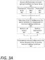
- FIG. 3Ais a high level flow chart describing an example method of preemptively configuring a sensor array 210 based on imminent lighting conditions.
- the high level method described in connection with FIG. 3Amay be performed by an example predictive configuration system 135 , as shown and described with respect to FIG. 1 , or an example predictive configuration system 200 , as shown and described with respect to FIG. 2 .
- the predictive configuration system 200can dynamically determine imminent lighting conditions for the sensor array 210 as the AV 100 travels along a current route ( 300 ). In doing so, the predictive configuration system 200 can utilize sensor data 107 (e.g., stereo camera sensor data 218 , LiDAR sensor data 211 , and/or radar sensor data 217 ) from the sensor array 210 ( 301 ).
- sensor data 107e.g., stereo camera sensor data 218 , LiDAR sensor data 211 , and/or radar sensor data 217
- the predictive configuration system 200can utilize sub-map data 292 from a current sub-map 134 , as described herein ( 302 ).
- the predictive configuration system 200can utilize route data 294 for the current route traveled by the AV 100 , and identify a current sub-map 134 being used, or to be used, by the AV's on-board data processing system 110 —which can continuously compare the sensor data 107 with stored sub-maps 133 to enable the control system 120 of the AV 100 to maneuver the AV 100 through road traffic to a particular destination.
- the sub-map data 292 from the current sub-map 134can comprise previously recorded video or stereo camera data that provides an indication of road features that can affect lighting conditions along the current route, such as overpasses, tunnels, bridges, buildings, billboards, illuminated signs, street lights, building lights, mountains, trees, sky exposure, and the like.
- the predictive configuration system 200can utilize the current sub-map 134 and, in certain cases, time data 281 to determine the imminent lighting conditions.
- the time data 281can indicate a time of day and/or a time of year to, for example, enable the predictive configuration system 200 to determine a current position of the Sun.
- the predictive configuration system 200can receive imminent lighting condition data via communications with other AVs, such as direct communications 162 from forward operating AVs 160 ( 303 ).
- the forward operating AVs 160can transmit the imminent lighting data by establishing a mesh network 169 with rearward AVs traveling along the same route.
- the communicationscan be relayed through a backend system that can manage transportation for any number of AVs throughout a given region (e.g., a city).
- constant communications between the AVs operating throughout the given region and the backend systemcan include transport instructions to service passenger pick-up requests, positional data, status updates, etc.
- the communicationsmay also include current lighting conditions throughout the given region to enable the AVs to preemptively configure their sensor arrays in anticipation of imminent lighting conditions as the travel throughout the given region.
- the continuous communications received by the AV 100can include the imminent lighting conditions for the AV 100 as the AV 100 travels along its current route.
- the predictive configuration system 200can respond to the imminent light conditions dynamically as described herein.
- the predictive configuration system 200can determine a set of configurations 277 for the sensor array to preemptively compensate for the imminent lighting conditions ( 305 ). Specifically, the predictive configuration system 200 can utilize brightness measurements, or calculate an estimated brightness using the sensor data 107 , and perform a lookup 272 in stored LUTs 275 for the sensor array 210 to identify an optimal set of configurations 277 for the passive sensors of the sensor array 210 (e.g., the stereo camera system 216 ).
- the predictive configurations system 200can include executable logic to perform an optimization for a particular sensor system (e.g., the stereo camera system 216 ) utilizing (i) the adjustable parameters of the sensor system, and (ii) the imminent lighting conditions ( 308 ).
- the optimization operationcan converge on an optimal set of configurations 277 for the sensor system to preemptively compensate for the imminent lighting conditions.
- the predictive configuration system 200can preemptively execute the set of configurations 277 for the sensor system to compensate for the imminent lighting conditions ( 310 ). Execution of the set of configurations may be timed by the predictive configuration system 200 to occur immediately prior to experiencing the imminent lighting conditions. For example, a set of configurations 277 for the stereo camera system 216 to compensate for traveling into the shadow of an overpass may occur within a fraction of a second (e.g., on the order of microseconds) prior to the stereo camera system 216 entering the shadow.
- the process described with respect to FIG. 3Amay also be performed by the predictive configuration system 200 as the AV 200 travels through and emerges from the shadow on the other end of the overpass. Accordingly, the process described with respect to FIG. 3A may be performed by the predictive configuration system 200 dynamically as the AV 100 travels throughout a given region.
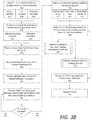
- FIG. 3Bis a low level flow chart describing an example method of preemptively configuring a sensor array 210 based on imminent lighting conditions.
- the low level method described in connection with FIG. 3Bmay be performed by an example predictive configuration system 135 , as shown and described with respect to FIG. 1 , or an example predictive configuration system 200 , as shown and described with respect to FIG. 2 .
- the predictive configuration system 200can maintain a set of LUTs 275 that include sensor configurations correlated to various lighting conditions for any number of passive sensor systems of the AV 100 ( 315 ).
- the LUTs 275can include configuration sets correlated to lighting conditions for a stereo camera system ( 317 ), infrared cameras ( 318 ), or any number of individual video recorders ( 319 ) of the AV 100 .
- the predictive configuration system 200can receive current sub-maps 134 that provide detailed surface data along the current route traveled by the AV 100 ( 320 ).
- the current sub-maps 134can indicate the imminent lighting conditions for a predetermined distance ahead of the AV 100 , certain light sources or lighting features that may affect the lighting conditions (e.g., buildings, overpasses, trees, etc.) ( 321 ). Additionally or alternatively, the current sub-maps 134 can indicate reflectance anomalies for the active sensor systems, as discussed below with respect to FIGS. 4A and 4B .
- the predictive sensor configuration system 200can receive sensor data 107 from the sensor array 210 of the AV 100 ( 325 ).
- the sensor data 107may indicate upcoming changes in lighting conditions to enable the predictive configuration system 200 to preemptively adjust the sensor array 210 to compensate for the imminent lighting conditions.
- the AV 100can also receive communications 162 indicating the imminent lighting conditions from forward operating AVs 160 directly (e.g., via a mesh network 169 ) ( 330 ) or from a backend system ( 335 ), as described.
- the predictive configuration system 200can calculate a brightness differential between current lighting conditions and anticipated lighting conditions ( 340 ). For example, the lighting change may have minimal effect on data quality for the on-board data processing system 110 . Accordingly, the predictive configuration system 200 can determine whether a predetermined threshold of brightness differential will be exceeded (e.g., ⁇ (x) lux) ( 345 ). If not ( 347 ), then the predictive configuration system 200 can continue to calculate brightness differentials as the AV 100 travels along the current route ( 240 ).
- a predetermined threshold of brightness differentiale.g., ⁇ (x) lux
- the predictive configuration system 200can determine the imminent light conditions for the passive sensors ( 350 ) from the sensor array 210 itself ( 351 ), the sub-map data 292 , and/or the other AVs 160 or backend system ( 353 ).
- the dynamic lag between the measured inputs and applied outputscan possibly induce oscillations in the internal state; also known as hysteresis behaviors. Such unwanted phenomenon can be eliminated by filtering signals so that the output reacts less rapidly than it otherwise would, by taking recent history into account. Such method can be implemented in the predictive configuration system 200 on the received sensor data 107 to filter out unwanted oscillatory behaviors.
- the predictive configuration system 200can then determine a set of configurations 277 for any number of the passive sensor systems to preemptively compensate for the imminent lighting conditions ( 355 ). As described above, the predictive configuration system 200 can do so by performing an optimization using the adjustable parameters of the sensor system and the imminent lighting conditions ( 357 ). Alternatively, the predictive configuration system 200 can perform a lookup 272 in the LUTs 275 based on the imminent lighting conditions ( 359 ). Accordingly, the predictive configuration system 200 can execute the set of configurations 277 for the sensor system (e.g., the stereo camera system 216 ) in a timely manner.
- the sensor systeme.g., the stereo camera system 216
- the configurationsmay configure adjustable parameters such as the aperture settings, resolution, frame rate and/or shutter speed, color temperature settings, gain or ISO settings, saturation and contrast settings, focus, and the like.
- the predictive configuration system 200can repeat each step of the process shown in FIG. 3B continuously as the AV 100 travels throughout the given region ( 365 ).
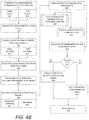
- FIG. 4Ais a high level flow chart describing an example method of preemptively configuring a sensor array 210 based on detected reflectance anomalies.
- FIG. 4Areference may be made to like reference characters representing various features of FIGS. 1 and 2 for illustrative purposes.
- the high level method described in connection with FIG. 4Amay be performed by an example predictive configuration system 135 , as shown and described with respect to FIG. 1 , or an example predictive configuration system 200 , as shown and described with respect to FIG. 2 .
- the predictive configuration system 200can dynamically determine reflectance anomalies for the sensor array 210 of the AV 100 ( 400 ).
- reflectance anomaliescan be identified from the sensor data 107 (e.g., the LiDAR sensor data 211 and/or the radar sensor data 217 ). Additionally or alternatively, the reflectance anomalies may be determined from current sub-maps 134 that can be analyzed by the predictive configuration system 200 ( 402 ). In further variations, the reflectance anomalies can be indicated in communications 162 received from other AVs, such as forward operating AVs 160 along the same current route as the AV 100 .
- the predictive configuration system 200can determine a set of configurations 277 for the active sensor system(s) to preemptively compensate for the identified reflectance anomalies ( 405 ).
- the predictive configuration system 200can determine the set of configurations 277 by performing a lookup 272 in the LUTs 275 which can correlate active sensor settings to the characteristics of a particular reflectance anomaly ( 407 ).
- a detected reflectance anomaly for the LiDAR system 212may be positively identified if certain adjustments are made to the LiDAR system 212 . These adjustments may include adjustments to beam frequency or laser power level, a scan rate, a sensitivity of the LiDAR system's photodetector, and the like.
- the predictive configuration system 200can perform an optimization utilizing the adjustable parameters of the active sensor system and the characteristics of the detected reflectance anomaly ( 408 ).
- the radar system 214can be adjusted to increase or decrease the wavelength (or pulse width) of the carrier signal which can be configured to reflect rather than be absorbed or dispersed by certain materials or coatings.
- the optimizationcan converge on an optimal carrier signal setting for the radar system 214 that can maximize a probability of positively identifying the reflectance anomaly.
- the predictive configuration system 200can preemptively execute the set of configurations 277 for the active sensor system(s) ( 410 ).
- the set of configurations 277can be executed immediately once they are determined in order to positively identify whether the reflectance anomaly can be disregarded, or whether it can be considered a potential hazard by the AV's on-board data processing system 110 .
- FIG. 4Bis a low level flow chart describing an example method of preemptively configuring a sensor array 210 based on detected reflectance anomalies.
- FIG. 4Breference may be made to like reference characters representing various features of FIGS. 1 and 2 for illustrative purposes.
- the low level method described in connection with FIG. 4Bmay be performed by an example predictive configuration system 135 , as shown and described with respect to FIG. 1 , or an example predictive configuration system 200 , as shown and described with respect to FIG. 2 . Referring to FIG.
- the predictive configuration system 200can maintain a set of LUTs 275 that include various sensor configurations that can be executed to adjust the parameters of the active sensor systems of the AV 100 in order to attempt to positively identify the reflectance anomaly ( 415 ).
- the LUTs 275can store various sets of sensor configurations that are correlated to certain characteristics of each detected anomaly for the radar system 214 ( 417 ) and/or the LiDAR system 212 ( 419 ) of the AV 100 .
- the predictive configuration system 200can receive active sensor data from each of the active sensors in the sensor array 210 ( 420 ).
- the predictive configuration system 200can receive live radar sensor data 217 and/or live LiDAR sensor data 211 from the respect radar system 214 and LiDAR system 212 in order to detect potential reflectance anomalies.
- the predictive configuration system 200can analyze current sub-map 134 to identify certain reflectance anomalies in the sub-maps 134 ( 425 ).
- the current sub-maps 134can include radar sub-maps that include previously recorded surface radar data showing the current route traveled by the AV 100 ( 427 ).
- the current sub-maps 134can also include LiDAR sub-maps that include recorded LiDAR data showing detailed features along the current route traveled by the AV 100 ( 429 ).
- the predictive configuration system 200can analyze each sub-map to identify reflectance anomalies in the previously recorded data.
- the predictive configuration system 200can receive communications 162 indicating the reflectance anomalies along the route from forward operating AVs 160 or from a backend system ( 430 ).
- the predictive configuration system 200can dynamically detect reflectance anomalies that affect each of the active sensors, such as the radar sensor system 214 or the LiDAR sensor system 212 ( 435 ). In some aspects, the predictive configuration system 200 can determine certain characteristics for each of the reflectance anomalies ( 440 ), such as whether they tend disperse or scatter the emitted electromagnetic signals ( 442 ), or whether they tend to absorb the signals ( 444 ). Other characteristics of the type of backscattering may be useful in identifying the specific object or phenomenon responsible for the reflectance anomaly. For example, diffuse reflection and/or Mie scattering can signify dust, smoke, fog, or light rain, whereas a moderate or strong backscatter can indicate heavier precipitation (e.g., rain, snow, or hail).
- the predictive configuration system 200can determine a set of configurations 277 for an affected active sensor system ( 445 ).
- the set of configurations 277can be determined by performing an optimization operation utilizing the adjustable parameters of the active sensor system (e.g., a carrier signal frequency, scan rate, beam frequency or beam width, a field of view, etc.) based on the characteristics of the reflectance anomaly ( 447 ).
- the optimizationcan converge on an optimal set of configurations that have a highest probability of resolving, or positively identifying, the anomaly.
- the predictive configuration system 200can perform a lookup 272 in the LUTs 275 based on the characteristics of the reflectance anomaly to select an optimal configuration set 277 ( 449 ).
- LiDAR sensor data 211may indicate a reflectance anomaly corresponding to a darkly painted vehicle parked on the street.
- the anomalymay show up as a dark patch in the LiDAR sensor data 211 .
- the predictive configuration systemcan identify that the anomaly is absorbing most of the emitted radiation from the LiDAR system 212 , and can increase or decrease the laser frequency to attempt to positively identify the vehicle in the LiDAR sensor data 211 .
- the LiDAR system 212receive multiple reflectance, or abnormal multiple reflectance, from certain object that have varying degrees of reflectance.
- the data processing systemcan identify certain patterns in the multiple reflectance returns to detect such objects. Positive identification of anomalies may be crucial for the AV 100 during operation in order to correlate objects across data sets to reinforce confident decision-making by the data processing system 110 and the AV control system 120 during operation.
- the predictive configuration system 200can execute the set of configurations 277 determined for each of the active sensor systems ( 450 ) in order to attempt to positively identify the reflectance anomaly.
- predictive configuration system 200can determine whether the reflectance anomaly has been identified ( 455 ).
- the predictive configuration system 200can attempt to identify the anomaly itself, or can receive a positive identification indicator from the data processing system 110 , whose purpose is to identify potential hazards. If the anomaly has not been resolved ( 457 ), then the predictive configuration system 200 can transmit a data priority signal 138 to the on-board data processing system 100 to prioritize data from other sensor systems of the sensor array 210 ( 460 ).
- the predictive configuration system 200can revert the settings of the active sensor system back to original or default settings, or lower power settings, once the anomaly has passed the sensor array's 210 field of view ( 465 ). Furthermore, since the process shown in FIGS. 4A and 4B are dynamic processes, the predictive configuration system 200 can repeat each step of the process shown continuously as the AV 100 travels throughout the given region ( 470 ).
- FIG. 5is a block diagram that illustrates a computer system 500 upon which examples described herein may be implemented.
- a computer system 500can be implemented on, for example, a server or combination of servers.
- the computer system 500may be implemented as the predictive configuration system 135 or 200 as shown and described with respect to FIGS. 1 and 2 .
- the functions of the predictive configuration system 200can be implemented as part of the on-board data processing system 110 of the AV 100 as shown and described with respect to FIG. 1 —which itself may be represented by the computer system 500 shown in FIG. 5 .
- the predictive configuration system 200may also be implemented using a standalone system or a combination of multiple computer systems 500 as described in connection with FIG. 5 .
- the computer system 500includes processing resources 510 , a main memory 520 , a read-only memory (ROM) 530 , a storage device 540 , and a communication interface 550 .
- the computer system 500includes at least one processor 510 for processing information stored in the main memory 520 , such as provided by a random access memory (RAM) or other dynamic storage device, for storing information and instructions which are executable by the processor 510 .
- the main memory 520also may be used for storing temporary variables or other intermediate information during execution of instructions to be executed by the processor 510 .
- the computer system 500may also include the ROM 530 or other static storage device for storing static information and instructions for the processor 510 .
- a storage device 540such as a magnetic disk or optical disk, is provided for storing information and instructions.
- the communication interface 550enables the computer system 500 to communicate with the components of the AV subsystems 580 (e.g., the sensor array 210 ) through use of wireless electronic links or a wired interface such as an internal and/or external bus. Using the electronic link, the computer system 500 can communicate with the AV subsystems 680 , such as the sensor array 105 , the AV control system 120 , the communication interface 115 , or the data processing system 100 of the AV 100 , as shown and described in connection with FIGS. 1 and 2 .
- the AV subsystems 680such as the sensor array 105 , the AV control system 120 , the communication interface 115 , or the data processing system 100 of the AV 100 , as shown and described in connection with FIGS. 1 and 2 .
- the computer system 500receives sensor data 582 via a set of sensors of the AV 100 , and/or data 584 from other AV systems or proximate AVs that indicate imminent lighting conditions or reflectance anomalies along the current route traveled.
- the executable instructions stored in the memory 530can include optimization instructions 522 , which the processor 510 executes to determine and execute a set of configuration commands 554 for a particular sensor system to proactively adjust the parameters of the sensor system in order to preemptively compensate for imminent lighting conditions or positively identify a reflectance anomaly.
- the processor 510is configured with software and/or other logic to perform one or more processes, steps and other functions described with implementations, such as described in connection with FIGS. 1-4B , and elsewhere in the present application.
- Examples described hereinare related to the use of the computer system 600 for implementing the techniques described herein. According to one example, those techniques are performed by the computer system 500 in response to the processor 510 executing one or more sequences of one or more instructions contained in the main memory 520 . Such instructions may be read into the main memory 520 from another machine-readable medium, such as the storage device 540 . Execution of the sequences of instructions contained in the main memory 520 causes the processor 510 to perform the process steps described herein. In alternative implementations, hard-wired circuitry may be used in place of or in combination with software instructions to implement examples described herein. Thus, the examples described are not limited to any specific combination of hardware circuitry and software.
Landscapes
- Engineering & Computer Science (AREA)
- Radar, Positioning & Navigation (AREA)
- Remote Sensing (AREA)
- Physics & Mathematics (AREA)
- General Physics & Mathematics (AREA)
- Computer Networks & Wireless Communication (AREA)
- Electromagnetism (AREA)
- Automation & Control Theory (AREA)
- Aviation & Aerospace Engineering (AREA)
- Signal Processing (AREA)
- Transportation (AREA)
- Mechanical Engineering (AREA)
- Mathematical Physics (AREA)
- Traffic Control Systems (AREA)
- Health & Medical Sciences (AREA)
- Computing Systems (AREA)
- General Health & Medical Sciences (AREA)
- Medical Informatics (AREA)
Abstract
Description
Claims (20)
Priority Applications (1)
| Application Number | Priority Date | Filing Date | Title |
|---|---|---|---|
| US16/206,660US10684361B2 (en) | 2015-12-16 | 2018-11-30 | Predictive sensor array configuration system for an autonomous vehicle |
Applications Claiming Priority (3)
| Application Number | Priority Date | Filing Date | Title |
|---|---|---|---|
| US14/971,850US9840256B1 (en) | 2015-12-16 | 2015-12-16 | Predictive sensor array configuration system for an autonomous vehicle |
| US15/694,493US10220852B2 (en) | 2015-12-16 | 2017-09-01 | Predictive sensor array configuration system for an autonomous vehicle |
| US16/206,660US10684361B2 (en) | 2015-12-16 | 2018-11-30 | Predictive sensor array configuration system for an autonomous vehicle |
Related Parent Applications (1)
| Application Number | Title | Priority Date | Filing Date |
|---|---|---|---|
| US15/694,493ContinuationUS10220852B2 (en) | 2015-12-16 | 2017-09-01 | Predictive sensor array configuration system for an autonomous vehicle |
Publications (2)
| Publication Number | Publication Date |
|---|---|
| US20190113607A1 US20190113607A1 (en) | 2019-04-18 |
| US10684361B2true US10684361B2 (en) | 2020-06-16 |
Family
ID=60516296
Family Applications (3)
| Application Number | Title | Priority Date | Filing Date |
|---|---|---|---|
| US14/971,850Active2036-01-04US9840256B1 (en) | 2015-12-16 | 2015-12-16 | Predictive sensor array configuration system for an autonomous vehicle |
| US15/694,493ActiveUS10220852B2 (en) | 2015-12-16 | 2017-09-01 | Predictive sensor array configuration system for an autonomous vehicle |
| US16/206,660ActiveUS10684361B2 (en) | 2015-12-16 | 2018-11-30 | Predictive sensor array configuration system for an autonomous vehicle |
Family Applications Before (2)
| Application Number | Title | Priority Date | Filing Date |
|---|---|---|---|
| US14/971,850Active2036-01-04US9840256B1 (en) | 2015-12-16 | 2015-12-16 | Predictive sensor array configuration system for an autonomous vehicle |
| US15/694,493ActiveUS10220852B2 (en) | 2015-12-16 | 2017-09-01 | Predictive sensor array configuration system for an autonomous vehicle |
Country Status (1)
| Country | Link |
|---|---|
| US (3) | US9840256B1 (en) |
Cited By (2)
| Publication number | Priority date | Publication date | Assignee | Title |
|---|---|---|---|---|
| US11353870B2 (en)* | 2018-12-31 | 2022-06-07 | Baidu Usa Llc | Autonomous driving computing and storage expansion device with flexible host and client configuration |
| US11520331B2 (en)* | 2018-12-28 | 2022-12-06 | Intel Corporation | Methods and apparatus to update autonomous vehicle perspectives |
Families Citing this family (44)
| Publication number | Priority date | Publication date | Assignee | Title |
|---|---|---|---|---|
| AU2014239979B2 (en) | 2013-03-15 | 2017-06-22 | Aurora Operations, Inc. | Methods, systems, and apparatus for multi-sensory stereo vision for robotics |
| US9616773B2 (en) | 2015-05-11 | 2017-04-11 | Uber Technologies, Inc. | Detecting objects within a vehicle in connection with a service |
| US10712160B2 (en) | 2015-12-10 | 2020-07-14 | Uatc, Llc | Vehicle traction map for autonomous vehicles |
| US10338225B2 (en) | 2015-12-15 | 2019-07-02 | Uber Technologies, Inc. | Dynamic LIDAR sensor controller |
| US9841763B1 (en) | 2015-12-16 | 2017-12-12 | Uber Technologies, Inc. | Predictive sensor array configuration system for an autonomous vehicle |
| US9840256B1 (en)* | 2015-12-16 | 2017-12-12 | Uber Technologies, Inc. | Predictive sensor array configuration system for an autonomous vehicle |
| US10281923B2 (en) | 2016-03-03 | 2019-05-07 | Uber Technologies, Inc. | Planar-beam, light detection and ranging system |
| US9990548B2 (en) | 2016-03-09 | 2018-06-05 | Uber Technologies, Inc. | Traffic signal analysis system |
| US10077007B2 (en)* | 2016-03-14 | 2018-09-18 | Uber Technologies, Inc. | Sidepod stereo camera system for an autonomous vehicle |
| US10459087B2 (en) | 2016-04-26 | 2019-10-29 | Uber Technologies, Inc. | Road registration differential GPS |
| US9672446B1 (en) | 2016-05-06 | 2017-06-06 | Uber Technologies, Inc. | Object detection for an autonomous vehicle |
| US9952317B2 (en)* | 2016-05-27 | 2018-04-24 | Uber Technologies, Inc. | Vehicle sensor calibration system |
| US20180005052A1 (en) | 2016-07-01 | 2018-01-04 | Uber Technologies, Inc. | Static object detection for operating autonomous vehicle |
| KR20180025591A (en)* | 2016-09-01 | 2018-03-09 | 삼성전자주식회사 | Control method and apparatus of vision sensor for automatic driving car |
| US11092690B1 (en)* | 2016-09-22 | 2021-08-17 | Apple Inc. | Predicting lidar data using machine learning |
| US10845470B2 (en)* | 2016-11-16 | 2020-11-24 | Waymo Llc | Methods and systems for protecting a light detection and ranging (LIDAR) device |
| WO2018160724A1 (en) | 2017-02-28 | 2018-09-07 | Wayfarer, Inc. | Transportation system |
| US10479376B2 (en) | 2017-03-23 | 2019-11-19 | Uatc, Llc | Dynamic sensor selection for self-driving vehicles |
| US10746858B2 (en) | 2017-08-17 | 2020-08-18 | Uatc, Llc | Calibration for an autonomous vehicle LIDAR module |
| US10775488B2 (en) | 2017-08-17 | 2020-09-15 | Uatc, Llc | Calibration for an autonomous vehicle LIDAR module |
| US11099264B2 (en)* | 2017-09-20 | 2021-08-24 | Motional Ad Llc | Variable range and frame-rate radar operation for automated vehicle |
| US10914820B2 (en) | 2018-01-31 | 2021-02-09 | Uatc, Llc | Sensor assembly for vehicles |
| US10611389B2 (en) | 2018-02-12 | 2020-04-07 | Vinod Khosla | Autonomous rail or off rail vehicle movement and system among a group of vehicles |
| US11084512B2 (en) | 2018-02-12 | 2021-08-10 | Glydways, Inc. | Autonomous rail or off rail vehicle movement and system among a group of vehicles |
| US10618537B2 (en) | 2018-02-12 | 2020-04-14 | Vinod Khosla | Autonomous rail or off rail vehicle movement and system among a group of vehicles |
| US10613550B2 (en) | 2018-02-12 | 2020-04-07 | Vinod Khosla | Autonomous rail vehicle movement and system among a group of vehicles on a rail system |
| US10884115B2 (en) | 2018-03-09 | 2021-01-05 | Waymo Llc | Tailoring sensor emission power to map, vehicle state, and environment |
| US11334753B2 (en) | 2018-04-30 | 2022-05-17 | Uatc, Llc | Traffic signal state classification for autonomous vehicles |
| US10872419B2 (en)* | 2018-09-04 | 2020-12-22 | GM Global Technology Operations LLC | Method and apparatus for evaluating a vehicle travel surface |
| DE102018123779A1 (en)* | 2018-09-26 | 2020-03-26 | HELLA GmbH & Co. KGaA | Method and device for improving object detection of a radar device |
| WO2020080180A1 (en)* | 2018-10-15 | 2020-04-23 | 日本電気株式会社 | Information processing device, sensing system, method, program, and storage medium |
| CN113961005A (en) | 2018-10-22 | 2022-01-21 | 科沃斯机器人股份有限公司 | Travel control method, surface cleaning robot, and storage medium |
| US11914367B2 (en) | 2018-12-11 | 2024-02-27 | GM Global Technology Operations LLC | Sun-aware routing and controls of an autonomous vehicle |
| US11294029B2 (en)* | 2019-04-16 | 2022-04-05 | GM Global Technology Operations LLC | Radar system and method for updating waveform parameters |
| EP4290878A3 (en)* | 2019-07-23 | 2024-03-06 | R-Go Robotics Ltd | Techniques for co-optimization of motion and sensory control |
| US11665379B2 (en)* | 2019-11-26 | 2023-05-30 | Photo Sensitive Cinema (PSC) | Rendering image content as time-spaced frames |
| KR20210100518A (en)* | 2020-02-06 | 2021-08-17 | 엘지전자 주식회사 | Robot cleaner and control method thereof |
| EP4121331A4 (en) | 2020-03-20 | 2024-05-01 | Glydways, Inc. | VEHICLE CONTROL DIAGRAMS FOR AUTONOMOUS VEHICLE SYSTEM |
| US11823458B2 (en) | 2020-06-18 | 2023-11-21 | Embedtek, LLC | Object detection and tracking system |
| AU2021102368A4 (en)* | 2021-01-22 | 2021-06-24 | 4AI Systems Holdings Pty Ltd | A Sensor Device for Vehicles |
| US11934198B2 (en)* | 2021-03-11 | 2024-03-19 | 6 River Systems, Llc | Systems and methods for autonomous vehicle operation |
| US11800085B2 (en) | 2021-07-22 | 2023-10-24 | Argo AI, LLC | Motorized mounting device for positioning an optical element within a field-of-view of an optical sensor and method of use |
| US11887475B1 (en) | 2021-12-13 | 2024-01-30 | Ford Global Technologies, Llc | Systems and methods for controlling a programmable traffic light |
| US12012108B1 (en)* | 2022-03-31 | 2024-06-18 | Zoox, Inc. | Prediction models in autonomous vehicles using modified map data |
Citations (252)
| Publication number | Priority date | Publication date | Assignee | Title |
|---|---|---|---|---|
| US5144685A (en) | 1989-03-31 | 1992-09-01 | Honeywell Inc. | Landmark recognition for autonomous mobile robots |
| JPH08334365A (en) | 1995-06-09 | 1996-12-17 | Zanavy Informatics:Kk | Present location calculating device |
| US5751852A (en) | 1996-04-29 | 1998-05-12 | Xerox Corporation | Image structure map data structure for spatially indexing an imgage |
| US5809179A (en) | 1996-05-31 | 1998-09-15 | Xerox Corporation | Producing a rendered image version of an original image using an image structure map representation of the image |
| US5864214A (en) | 1994-12-15 | 1999-01-26 | Asc Incorporated | Storage compartment sensor system for use with an automotive vehicle |
| US6023655A (en) | 1996-12-16 | 2000-02-08 | Xanavi Informatics Corporation | Map database apparatus |
| WO2001065454A2 (en) | 2000-02-29 | 2001-09-07 | United Parcel Service Of America, Inc. | Delivery system and method for vehicles and the like |
| US6385539B1 (en) | 1999-08-13 | 2002-05-07 | Daimlerchrysler Ag | Method and system for autonomously developing or augmenting geographical databases by mining uncoordinated probe data |
| US20020109610A1 (en) | 2001-02-15 | 2002-08-15 | Yoram Katz | Parking status control system and method |
| US20020161501A1 (en) | 1999-06-03 | 2002-10-31 | Dulin Jacques M. | Hot vehicle safety system and methods of preventing passenger entrapment and heat suffocation |
| US20030001509A1 (en) | 2001-06-29 | 2003-01-02 | Joel Leleve | Method and apparatus for detecting the state of humidity on a road on which a vehicle is travelling |
| US20030040944A1 (en) | 2001-08-22 | 2003-02-27 | Hileman Ryan M. | On-demand transportation system |
| US6542111B1 (en) | 2001-08-13 | 2003-04-01 | Yazaki North America, Inc. | Path prediction for vehicular collision warning system |
| US20030151547A1 (en) | 2002-02-08 | 2003-08-14 | Anthony Mauro | Directly acquiring precision code GPS signals |
| US20040085227A1 (en) | 2002-11-01 | 2004-05-06 | Makoto Mikuriya | Data architecture of map data, data architecture of update instruction data, map information processing apparatus, and map information providing apparatus |
| US20040133330A1 (en) | 2002-08-12 | 2004-07-08 | Toyota Jidosha Kabushiki Kaisha | Self aligning torque reference value calculating apparatus, method thereof, and road surface friction state estimating apparatus, method thereof |
| US6795031B1 (en) | 2002-07-12 | 2004-09-21 | Yazaki North America, Inc. | Mechanically scanned parabolic reflector antenna |
| US20040204812A1 (en) | 2003-04-09 | 2004-10-14 | Continental Teves Inc. | Road recognition system |
| US20050010350A1 (en) | 2003-07-07 | 2005-01-13 | Fuji Jukogyo Kabushiki Kaisha | Road-surface friction coefficient estimating device and road-surface friction coefficient estimating method |
| US20050044944A1 (en) | 2003-08-26 | 2005-03-03 | Fuji Jukogyo Kabushiki Kaisha | Apparatus and method of judging road surface conditions for vehicle |
| JP2005115911A (en) | 2003-09-16 | 2005-04-28 | Denso Corp | Device for preventing thing from being left in vehicle |
| US20050100207A1 (en) | 1996-06-28 | 2005-05-12 | Kurt Konolige | Realtime stereo and motion analysis on passive video images using an efficient image-to-image comparison algorithm requiring minimal buffering |
| US20050113999A1 (en) | 2003-11-26 | 2005-05-26 | Nissan Motor Co., Ltd. | Automotive lane deviation prevention apparatus |
| US20050155685A1 (en) | 2002-02-22 | 2005-07-21 | Michelin Recherche Et Technique S.A. | Elastic tire for measuring the grip of a vehicle equipped therewith on a ground |
| US20050222744A1 (en) | 2004-03-25 | 2005-10-06 | Kunio Sakata | Behavior control apparatus and method for a vehicle |
| US20060002586A1 (en) | 2004-06-15 | 2006-01-05 | Manoj Aggarwal | Method and apparatus for detecting left objects |
| US20060126975A1 (en) | 2004-12-10 | 2006-06-15 | Mckellar Randy R | Easy opening rear seam bags and packaging methods |
| US20060128087A1 (en)* | 2000-11-09 | 2006-06-15 | Canesta, Inc. | Methods and devices for improved charge management for three-dimensional and color sensing |
| JP2006159939A (en) | 2004-12-02 | 2006-06-22 | Xanavi Informatics Corp | Notice device for in-cabin object to be informed |
| US7102496B1 (en) | 2002-07-30 | 2006-09-05 | Yazaki North America, Inc. | Multi-sensor integration for a vehicle |
| US20060208911A1 (en) | 2005-03-21 | 2006-09-21 | Davis Leroychelle | Child carseat alert system |
| US20060217882A1 (en) | 2005-03-22 | 2006-09-28 | Denso Corporation | Vehicular navigation system |
| US20060223637A1 (en) | 2005-03-31 | 2006-10-05 | Outland Research, Llc | Video game system combining gaming simulation with remote robot control and remote robot feedback |
| US7124027B1 (en) | 2002-07-11 | 2006-10-17 | Yazaki North America, Inc. | Vehicular collision avoidance system |
| US20060259225A1 (en) | 2003-09-03 | 2006-11-16 | Nsk Ltd. | Stability control apparatus and load measuring instrument for wheel supporting rolling bearing unit |
| US20070050121A1 (en) | 2004-04-02 | 2007-03-01 | Dieter Ammon | Method for determining a coefficient of friction |
| US20070229490A1 (en) | 2006-03-31 | 2007-10-04 | Research In Motion Limited | Map version control methods and apparatus for updating the use of network-maintained map data sets for mobile communication devices |
| US20070268364A1 (en) | 2006-05-17 | 2007-11-22 | The Boeing Company | Moving object detection |
| US20080033645A1 (en) | 2006-08-03 | 2008-02-07 | Jesse Sol Levinson | Pobabilistic methods for mapping and localization in arbitrary outdoor environments |
| JP2008027239A (en) | 2006-07-21 | 2008-02-07 | Denso Corp | Apparatus for preventing belongings from being left behind |
| US20080040004A1 (en)* | 1994-05-23 | 2008-02-14 | Automotive Technologies International, Inc. | System and Method for Preventing Vehicular Accidents |
| US20080129475A1 (en) | 2000-09-08 | 2008-06-05 | Automotive Technologies International, Inc. | System and Method for In-Vehicle Communications |
| US20080162036A1 (en) | 1997-10-22 | 2008-07-03 | Intelligent Technologies International, Inc. | Vehicular Map Database Management Techniques |
| KR100862561B1 (en) | 2008-03-13 | 2008-10-09 | (주) 서돌 전자통신 | Traffic accident detection system |
| JP2008262459A (en) | 2007-04-13 | 2008-10-30 | Fujitsu Ten Ltd | Mislaying announcing device |
| US20090005961A1 (en) | 2004-06-03 | 2009-01-01 | Making Virtual Solid, L.L.C. | En-Route Navigation Display Method and Apparatus Using Head-Up Display |
| US20090010495A1 (en) | 2004-07-26 | 2009-01-08 | Automotive Systems Laboratory, Inc. | Vulnerable Road User Protection System |
| US20090043440A1 (en) | 2007-04-12 | 2009-02-12 | Yoshihiko Matsukawa | Autonomous mobile device, and control device and program product for the autonomous mobile device |
| US20090043439A1 (en) | 2005-07-26 | 2009-02-12 | Macdonald, Dettwiler & Associates, Inc. | Guidance, Navigation, and Control System for a Vehicle |
| US20090070034A1 (en) | 2006-03-17 | 2009-03-12 | Christopher L Oesterling | Method for recording an annotation and making it available for later playback |
| JP2009075756A (en) | 2007-09-19 | 2009-04-09 | Denso Corp | Apparatus for preventing thing from being left in vehicle |
| US20090150036A1 (en) | 2007-12-05 | 2009-06-11 | Craig William C | GPS-based traction control system and method using data transmitted between vehicles |
| US20090146813A1 (en) | 2007-12-10 | 2009-06-11 | Acropolis Engineering | Automobile forgotten passenger alarm and notification |
| US20090216600A1 (en)* | 2008-02-27 | 2009-08-27 | Montiss Llc | Systems and methods for arranging a transport transaction |
| US20090228204A1 (en) | 2008-02-04 | 2009-09-10 | Tela Atlas North America, Inc. | System and method for map matching with sensor detected objects |
| US20090306859A1 (en) | 2006-04-19 | 2009-12-10 | Marc Andre Tichy | Device and method for triggering passenger protection system in consideration of road grip coefficient |
| US20090319129A1 (en) | 2008-06-18 | 2009-12-24 | Gm Global Technology Operations, Inc. | Motor vehicle driver assisting method |
| US20090326991A1 (en) | 2008-06-27 | 2009-12-31 | E-Lantis Corporation | Gps and wireless integrated fleet management system and method |
| US20090322872A1 (en) | 2006-06-12 | 2009-12-31 | Karsten Muehlmann | Image acquisition system and method for distance determination using an image recording system |
| US20100013615A1 (en) | 2004-03-31 | 2010-01-21 | Carnegie Mellon University | Obstacle detection having enhanced classification |
| US20100020170A1 (en) | 2008-07-24 | 2010-01-28 | Higgins-Luthman Michael J | Vehicle Imaging System |
| US20100023214A1 (en) | 2006-12-22 | 2010-01-28 | Equos Research Co., Ltd. | Vehicle control device |
| US20100023213A1 (en) | 2006-12-22 | 2010-01-28 | Equos Research Co., Ltd. | Vehicle control device |
| US20100030460A1 (en) | 2007-03-29 | 2010-02-04 | Kimiyoshi Sawai | Map update data supply apparatus, map data update system, and map update data supply method |
| US20100165323A1 (en)* | 2008-12-29 | 2010-07-01 | Reinhold Fiess | Adaptive angle and power adaptation in 3d-micro-mirror lidar |
| US20100217491A1 (en) | 2007-07-02 | 2010-08-26 | Equos Research Co., Ltd. | Camber angle controlling device |
| US20100235083A1 (en) | 2007-03-27 | 2010-09-16 | Aisin Aw Co., Ltd. | Road map data structure, road map data storage medium, navigation device, and method of generating road map data |
| RU2400592C1 (en) | 2009-08-17 | 2010-09-27 | Александр Макарович Салдаев | Method of transport network creation |
| US20100250056A1 (en) | 2009-03-24 | 2010-09-30 | Ford Global Technologies, Llc | System and Method for Improving Vehicle Performance on Grade |
| US20100245123A1 (en) | 2009-03-27 | 2010-09-30 | Ford Global Technologies, Llc | Telematics system and method for traction reporting and control in a vehicle |
| US20100250052A1 (en) | 2009-03-26 | 2010-09-30 | Denso Corporation | In-vehicle monitor for monitoring vehicle status |
| US20100256836A1 (en) | 2009-04-06 | 2010-10-07 | Gm Global Technology Operations, Inc. | Autonomous vehicle management |
| US20100262359A1 (en) | 2009-04-14 | 2010-10-14 | Masaki Motoyama | Route search method and apparatus for navigation system utilizing map data of XML format |
| US20100274469A1 (en) | 2007-02-28 | 2010-10-28 | Aisin Aw Co., Ltd | Navigation device and data update system |
| US20100280751A1 (en) | 1997-10-22 | 2010-11-04 | Intelligent Technologies International, Inc. | Road physical condition monitoring techniques |
| US20100299063A1 (en) | 2009-05-21 | 2010-11-25 | Clarion Co., Ltd. | Current Position Determining Device and Current Position Determining Method |
| US20100295946A1 (en) | 2009-05-20 | 2010-11-25 | Reed William G | Long-range motion detection for illumination control |
| US20110012511A1 (en) | 2008-03-12 | 2011-01-20 | Toyota Jidosha Kabushiki Kaisha | Vehicle lighting device and lighting method |
| US20110046784A1 (en) | 2009-08-18 | 2011-02-24 | Noel Wayne Anderson | Asymmetric stereo vision system |
| US20110043377A1 (en) | 2009-08-24 | 2011-02-24 | Navteq North America, Llc | Providing Driving Condition Alerts Using Road Attribute Data |
| US20110054791A1 (en) | 2009-08-25 | 2011-03-03 | Southwest Research Institute | Position estimation for ground vehicle navigation based on landmark identification/yaw rate and perception of landmarks |
| US20110060478A1 (en) | 2009-09-09 | 2011-03-10 | Gm Global Technology Operations, Inc. | Vehicular terrain detection system and method |
| WO2011038018A1 (en) | 2009-09-23 | 2011-03-31 | Earthsearch Communications International, Inc. | Device and process for monitoring secure storage and delivery of items |
| WO2011055978A2 (en) | 2009-11-03 | 2011-05-12 | Samsung Electronics Co., Ltd. | User terminal, method for providing position and method for guiding route thereof |
| US7994465B1 (en)* | 2006-02-06 | 2011-08-09 | Microsoft Corporation | Methods and devices for improved charge management for three-dimensional and color sensing |
| US20110285982A1 (en) | 1995-06-07 | 2011-11-24 | Breed David S | Method and arrangement for obtaining information about objects around a vehicle |
| US20120006610A1 (en) | 2010-07-09 | 2012-01-12 | Erik Wallace | Telematics enhanced mobile device safety interlock |
| US20120045090A1 (en) | 2010-08-17 | 2012-02-23 | International Business Machines Corporation | Multi-mode video event indexing |
| CN102390370A (en) | 2011-10-25 | 2012-03-28 | 河海大学 | Stereoscopic vision based emergency treatment device and method for running vehicles |
| US20120083959A1 (en) | 2010-10-05 | 2012-04-05 | Google Inc. | Diagnosis and repair for autonomous vehicles |
| US20120121161A1 (en) | 2010-09-24 | 2012-05-17 | Evolution Robotics, Inc. | Systems and methods for vslam optimization |
| US20120158313A1 (en)* | 2010-12-21 | 2012-06-21 | Delphi Technologies, Inc. | Method and Device for Characterization and Sensing of Exhaust Gas and Control of Engines and Components for Aftertreatment of Exhaust Gases |
| JP2012127861A (en) | 2010-12-16 | 2012-07-05 | Sumitomo Electric Ind Ltd | Vehicle travel support system, computer program, and vehicle travel support method |
| US8245516B2 (en) | 2004-08-27 | 2012-08-21 | University Of Houston | Shape memory alloy actuated adaptive exhaust nozzle for jet engine |
| CN202394343U (en) | 2011-12-12 | 2012-08-22 | 浙江金刚汽车有限公司 | Voice prompt system for preventing forgetting articles on taxi |
| US8253799B2 (en) | 2007-07-27 | 2012-08-28 | Sportvision, Inc. | Detecting an object in an image using camera registration data indexed to location or camera sensors |
| US20120242492A1 (en) | 2011-03-25 | 2012-09-27 | Tov 1 LLC | Seat occupancy detection and display system |
| US20120283912A1 (en) | 2011-05-05 | 2012-11-08 | GM Global Technology Operations LLC | System and method of steering override end detection for automated lane centering |
| US20120296539A1 (en) | 2011-03-23 | 2012-11-22 | Tk Holdings Inc. | Driver assistance system |
| US20120310516A1 (en) | 2011-06-01 | 2012-12-06 | GM Global Technology Operations LLC | System and method for sensor based environmental model construction |
| US20120327410A1 (en) | 2011-06-23 | 2012-12-27 | Cvg Management Corporation | Non-contact media detection system using reflection/absoption spectroscopy |
| US20130015984A1 (en) | 2011-07-16 | 2013-01-17 | Denso Corporation | Vehicular wireless communication apparatus and communication system |
| US20130018575A1 (en) | 2010-03-19 | 2013-01-17 | Ralf Birken | Roaming Mobile Sensor Platform For Collecting Geo-Referenced Data and Creating Thematic Maps |
| US8364334B2 (en) | 2008-10-30 | 2013-01-29 | Honeywell International Inc. | System and method for navigating an autonomous vehicle using laser detection and ranging |
| US20130060461A1 (en) | 2011-09-07 | 2013-03-07 | INRO Technologies Limited | Method and apparatus for using pre-positioned objects to localize an industrial vehicle |
| US8412449B2 (en) | 2008-10-24 | 2013-04-02 | Gray & Company, Inc. | Control and systems for autonomously driven vehicles |
| US20130083159A1 (en) | 2010-06-24 | 2013-04-04 | Fujifilm Corporation | Stereoscopic panoramic image synthesis device, image capturing device, stereoscopic panoramic image synthesis method, recording medium, and computer program |
| US20130117321A1 (en) | 2011-11-07 | 2013-05-09 | Elektrobit Automotive Gmbh | Technique for structuring a navigation database |
| US20130215115A1 (en) | 2010-06-30 | 2013-08-22 | Barry Lynn Jenkins | Delivering and controlling streaming interactive media comprising rendered geometric, texture and lighting data |
| US8521352B1 (en) | 2012-05-07 | 2013-08-27 | Google Inc. | Controlling a vehicle having inadequate map data |
| RU132393U1 (en) | 2013-03-21 | 2013-09-20 | Федеральное государственное бюджетное образовательное учреждение высшего профессионального образования "Санкт-Петербургский государственный аграрный университет" | DEVICE FOR AUTOMATIC CONTROL OF SAFETY OF MOTION OF VEHICLE |
| US8559673B2 (en) | 2010-01-22 | 2013-10-15 | Google Inc. | Traffic signal mapping and detection |
| WO2013155661A1 (en) | 2012-04-16 | 2013-10-24 | Harman International (Shanghai) Management Co., Ltd. | A monitoring system in a vehicle and a method performed therein |
| US20130314503A1 (en)* | 2012-05-18 | 2013-11-28 | Magna Electronics Inc. | Vehicle vision system with front and rear camera integration |
| US20130325279A1 (en) | 2012-06-04 | 2013-12-05 | Honda Motor Co., Ltd. | Display apparatus for vehicles |
| US20140005933A1 (en) | 2011-09-30 | 2014-01-02 | Evolution Robotics, Inc. | Adaptive Mapping with Spatial Summaries of Sensor Data |
| US20140002277A1 (en) | 2010-11-08 | 2014-01-02 | Daniel Fulger | Vehicle data system and method |
| US20140025232A1 (en) | 2011-08-25 | 2014-01-23 | Ford Global Technologies, Llc | Method and Apparatus for a Near Field Communication System to Exchange Occupant Information |
| US20140046585A1 (en) | 2012-08-10 | 2014-02-13 | Telogis, Inc. | Real-time computation of vehicle service routes |
| US20140047250A1 (en) | 2009-02-27 | 2014-02-13 | Atmel Corporation | Single pin communication mechanism |
| US20140081573A1 (en) | 2012-09-20 | 2014-03-20 | Google Inc. | Detecting road weather conditions |
| US20140118363A1 (en) | 2012-10-26 | 2014-05-01 | Nvidia Corporation | Managing deferred contexts in a cache tiling architecture |
| WO2014072972A1 (en) | 2012-11-08 | 2014-05-15 | Maimoni Iris | System and method for determining whether items have been left in vehicles |
| US20140133330A1 (en) | 2012-11-09 | 2014-05-15 | Cisco Technology, Inc. | Apparatus, system, and method for providing energy management, profiles, and message blocks in a cable service environment |
| US20140136414A1 (en) | 2006-03-17 | 2014-05-15 | Raj Abhyanker | Autonomous neighborhood vehicle commerce network and community |
| US20140188386A1 (en) | 2012-12-28 | 2014-07-03 | Hitachi, Ltd. | Map distribution server for automotive navigation systems, map data distribution system, and road difference data production method |
| US20140188363A1 (en) | 2011-08-25 | 2014-07-03 | Wabco Gmbh | Method and Control Device fort Open-Loop or Closed-Loop Control of a Vehicle Brake System |
| WO2014108267A1 (en) | 2013-01-14 | 2014-07-17 | Continental Automotive Gmbh | System for transmitting baggage items |
| US20140222298A1 (en) | 2013-02-03 | 2014-08-07 | Michael H. Gurin | Systems For a Shared Vehicle |
| US8825265B1 (en) | 2012-03-16 | 2014-09-02 | Google Inc. | Approach for consolidating observed vehicle trajectories into a single representative trajectory |
| US20140247357A1 (en) | 2011-11-30 | 2014-09-04 | Hiroyoshi Sekiguchi | Attached matter detector, and attached matter detection method |
| WO2014131400A1 (en) | 2013-02-28 | 2014-09-04 | Eberhard Göbel GmbH + Co | Rental vehicle and method for carrying out a rental transaction for a rental vehicle |
| WO2014147361A1 (en) | 2013-03-19 | 2014-09-25 | Massive Analytic Ltd. | Apparatus for controlling a land vehicle which is self-driving or partially self-driving |
| US20140302774A1 (en) | 2013-04-04 | 2014-10-09 | General Motors Llc | Methods systems and apparatus for sharing information among a group of vehicles |
| US20140307247A1 (en) | 2013-04-11 | 2014-10-16 | Google Inc. | Methods and Systems for Detecting Weather Conditions Including Wet Surfaces Using Vehicle Onboard Sensors |
| US20140306835A1 (en) | 2012-03-14 | 2014-10-16 | Flextronics Ap, Llc | Radar sensing and emergency response vehicle detection |
| US20140336842A1 (en) | 2013-05-09 | 2014-11-13 | Hyundai Motor Company | System and method for detecting road surface conditions |
| US20140336935A1 (en) | 2013-05-07 | 2014-11-13 | Google Inc. | Methods and Systems for Detecting Weather Conditions Using Vehicle Onboard Sensors |
| US20140340304A1 (en) | 2013-05-15 | 2014-11-20 | Google Inc. | Efficient fetching of a map data during animation |
| US8917190B1 (en) | 2013-01-23 | 2014-12-23 | Stephen Waller Melvin | Method of restricting turns at vehicle intersections |
| US20150003670A1 (en) | 2013-06-28 | 2015-01-01 | Bendix Commercial Vehicle Systems Llc | Measuring the range to an object, in an image, using size categorization |
| JP2015007874A (en) | 2013-06-25 | 2015-01-15 | 日産自動車株式会社 | Vehicle interior monitoring device |
| US20150035985A1 (en)* | 2013-08-01 | 2015-02-05 | Connaught Electronics Ltd. | Method for activating and deactivating an image correction function, camera system and motor vehicle |
| US20150061856A1 (en) | 2013-08-28 | 2015-03-05 | Harman International Industries, Incorporated | Providing alerts for objects left in a vehicle |
| DE102014114438A1 (en) | 2013-10-11 | 2015-04-16 | General Motors Llc | A method of providing fuel purchase options to a vehicle |
| US20150112585A1 (en) | 2013-10-22 | 2015-04-23 | Quicken Loans, Inc. | Communication System |
| CN104601648A (en) | 2013-10-31 | 2015-05-06 | 通用汽车环球科技运作有限责任公司 | Methods, systems and apparatus for providing notification that a wireless communication device has been left inside a vehicle |
| US20150124428A1 (en) | 2012-05-31 | 2015-05-07 | Osram Gmbh | Lens Having An Internal Reflection Layer |
| US9036865B2 (en) | 2012-09-12 | 2015-05-19 | International Business Machines Corporation | Location determination for an object using visual data |
| US20150142248A1 (en) | 2013-11-20 | 2015-05-21 | Electronics And Telecommunications Research Institute | Apparatus and method for providing location and heading information of autonomous driving vehicle on road within housing complex |
| US9045041B2 (en) | 2013-02-27 | 2015-06-02 | Here Global B.V. | Driver behavior from probe data for augmenting a data model |
| US20150166072A1 (en) | 2013-10-17 | 2015-06-18 | Richard M. Powers | Systems and methods for predicting weather performance for a vehicle |
| US20150203107A1 (en) | 2014-01-17 | 2015-07-23 | Ford Global Technologies, Llc | Autonomous vehicle precipitation detection |
| US20150202770A1 (en) | 2014-01-17 | 2015-07-23 | Anthony Patron | Sidewalk messaging of an autonomous robot |
| US20150210274A1 (en) | 2014-01-30 | 2015-07-30 | Mobileye Vision Technologies Ltd. | Systems and methods for lane end recognition |
| US9097800B1 (en) | 2012-10-11 | 2015-08-04 | Google Inc. | Solid object detection system using laser and radar sensor fusion |
| US20150224845A1 (en) | 2013-03-15 | 2015-08-13 | Levant Power Corporation | Active vehicle suspension system |
| US20150247733A1 (en)* | 2012-10-05 | 2015-09-03 | Denso Corporation | Map information processing device and storage medium |
| US20150251659A1 (en) | 2012-12-20 | 2015-09-10 | Continental Teves Ag & Co. Ohg | Friction Coefficient Estimation from Camera and Wheel Speed Data |
| US9139204B1 (en) | 2014-06-12 | 2015-09-22 | GM Global Technology Operations LLC | Road surface condition detection with recursive adaptive learning and validation |
| US20150266471A1 (en) | 2012-09-05 | 2015-09-24 | Google Inc. | Construction Zone Sign Detection Using Light Detection and Ranging |
| US9145140B2 (en) | 2012-03-26 | 2015-09-29 | Google Inc. | Robust method for detecting traffic signals and their associated states |
| US9158980B1 (en) | 2012-09-19 | 2015-10-13 | Google Inc. | Use of relationship between activities of different traffic signals in a network to improve traffic signal state estimation |
| US20150310146A1 (en) | 2014-04-29 | 2015-10-29 | Bayerische Motoren Werke Aktiengesellschaft | Detecting Static and Dynamic Objects |
| US20150331422A1 (en)* | 2013-12-31 | 2015-11-19 | Harbrick LLC | Autonomous Vehicle Interface System |
| US20150344038A1 (en) | 2014-05-30 | 2015-12-03 | Here Global B.V. | Dangerous Driving Event Reporting |
| US20150346727A1 (en) | 2015-08-12 | 2015-12-03 | Madhusoodhan Ramanujam | Parking Autonomous Vehicles |
| US20150362322A1 (en) | 2013-02-22 | 2015-12-17 | Aisin Aw Co | Navigation system, and control method and program for navigation system |
| US20150369617A1 (en) | 2014-06-20 | 2015-12-24 | Google Inc. | Integrating Online Navigation Data with Cached Navigation Data During Active Navigation |
| US9223013B2 (en) | 2006-01-04 | 2015-12-29 | Mobileye Vision Technologies Ltd. | Estimating distance to an object using a sequence of images recorded by a monocular camera |
| US20160009218A1 (en) | 2014-07-09 | 2016-01-14 | Toyota Jidosha Kabushiki Kaisha | Vehicular lighting apparatus |
| US20160016663A1 (en) | 2014-07-16 | 2016-01-21 | Ford Global Technologies, Llc | Automotive Drone Deployment System |
| US20160055744A1 (en) | 2014-08-19 | 2016-02-25 | Qualcomm Incorporated | Systems and methods for traffic efficiency and flow control |
| US20160054135A1 (en) | 2014-08-21 | 2016-02-25 | Here Global B.V. | Measuring Quality in Optimal Navigation Routes by Navigation Systems |
| US20160125608A1 (en) | 2014-11-04 | 2016-05-05 | Volvo Car Corporation | Methods and systems for enabling improved positioning of a vehicle |
| US20160133131A1 (en) | 2014-11-12 | 2016-05-12 | GM Global Technology Operations LLC | Use of participative sensing systems to enable enhanced road friction estimation |
| EP3032458A2 (en) | 2014-12-10 | 2016-06-15 | LG Electronics Inc. | Driver assistance for a vehicle |
| US20160167582A1 (en) | 2014-12-16 | 2016-06-16 | Here Global B.V. | Learning Lanes From Vehicle Probes |
| US20160176408A1 (en) | 2014-12-22 | 2016-06-23 | Here Global B.V. | Method and apparatus for providing road surface friction data for a response action |
| US20160178802A1 (en) | 2014-12-22 | 2016-06-23 | GM Global Technology Operations LLC | Road surface reflectivity detection by lidar sensor |
| US20160180171A1 (en) | 2014-12-17 | 2016-06-23 | Toyota Motor Engineering & Manufacturing North America, Inc. | Background map format for autonomous driving |
| US9383753B1 (en) | 2012-09-26 | 2016-07-05 | Google Inc. | Wide-view LIDAR with areas of special attention |
| US9386230B1 (en)* | 2015-06-12 | 2016-07-05 | Google Inc. | Day and night detection based on one or more of illuminant detection, lux level detection, and tiling |
| US20160207537A1 (en) | 2015-01-19 | 2016-07-21 | Toyota Jidosha Kabushiki Kaisha | Vehicle system |
| US9442487B1 (en) | 2014-08-15 | 2016-09-13 | Google Inc. | Classifier hierarchies for traffic light and traffic indicator detection |
| US20160267720A1 (en) | 2004-01-30 | 2016-09-15 | Electronic Scripting Products, Inc. | Pleasant and Realistic Virtual/Augmented/Mixed Reality Experience |
| US20160276131A1 (en) | 2015-03-18 | 2016-09-22 | Ims Nanofabrication Ag | Bi-Directional Double-Pass Multi-Beam Writing |
| US9488483B2 (en) | 2013-05-17 | 2016-11-08 | Honda Motor Co., Ltd. | Localization using road markings |
| US9494439B1 (en) | 2015-05-13 | 2016-11-15 | Uber Technologies, Inc. | Autonomous vehicle operated with guide assistance of human driven vehicles |
| US9507346B1 (en) | 2015-11-04 | 2016-11-29 | Zoox, Inc. | Teleoperation system and method for trajectory modification of autonomous vehicles |
| US20160349063A1 (en) | 2015-05-28 | 2016-12-01 | Google Inc. | Dynamically Integrating Offline and Online Data in a Geographic Application |
| US20160357188A1 (en) | 2015-06-05 | 2016-12-08 | Arafat M.A. ANSARI | Smart vehicle |
| US20160370191A1 (en) | 2015-06-22 | 2016-12-22 | Honda Motor Co., Ltd. | Map information update apparatus and map information update system |
| US20160368504A1 (en) | 2015-06-22 | 2016-12-22 | Robert Bosch Gmbh | Method and device for ascertaining a minimum value for the friction coefficient of a road segment |
| US20170008521A1 (en) | 2015-02-10 | 2017-01-12 | Mobileye Vision Technologies Ltd. | Autonomous vehicle speed calibration |
| US20170008522A1 (en) | 2015-07-06 | 2017-01-12 | Toyota Jidosha Kabushiki Kaisha | Control system of automated driving vehicle |
| US20170016731A1 (en) | 2014-03-24 | 2017-01-19 | Aisin Aw Co., Ltd. | Map information generation system, method, and program |
| US20170015318A1 (en) | 2014-03-03 | 2017-01-19 | Inrix Inc. | Personalization of automated vehicle control |
| US20170015317A1 (en) | 2015-07-13 | 2017-01-19 | Cruise Automation, Inc. | Method for image-based vehicle localization |
| US9552564B1 (en) | 2015-03-19 | 2017-01-24 | Amazon Technologies, Inc. | Autonomous delivery transportation network |
| US20170023659A1 (en) | 2015-05-08 | 2017-01-26 | 5D Robotics, Inc. | Adaptive positioning system |
| US20170059336A1 (en) | 2015-08-31 | 2017-03-02 | National Taipei University Of Technology | Dispatch system for autonomous vehicles |
| US20170090478A1 (en) | 2015-09-30 | 2017-03-30 | Ants Technology (Hk) Limited. | Systems and Methods for Autonomous Vehicle Navigation |
| US9631933B1 (en) | 2014-05-23 | 2017-04-25 | Google Inc. | Specifying unavailable locations for autonomous vehicles |
| US20170123421A1 (en) | 2015-11-04 | 2017-05-04 | Zoox, Inc. | Coordination of dispatching and maintaining fleet of autonomous vehicles |
| US20170120814A1 (en) | 2015-11-04 | 2017-05-04 | Zoox, Inc. | Method for robotic vehicle communication with an external environment via acoustic beam forming |
| US20170123429A1 (en) | 2015-11-04 | 2017-05-04 | Zoox, Inc. | Adaptive autonomous vehicle planner logic |
| US20170124781A1 (en) | 2015-11-04 | 2017-05-04 | Zoox, Inc. | Calibration for autonomous vehicle operation |
| US20170146991A1 (en) | 2015-11-24 | 2017-05-25 | Northrop Grumman Systems Corporation | Spatial-temporal forecasting for predictive situational awareness |
| US9672446B1 (en) | 2016-05-06 | 2017-06-06 | Uber Technologies, Inc. | Object detection for an autonomous vehicle |
| US9672734B1 (en) | 2016-04-08 | 2017-06-06 | Sivalogeswaran Ratnasingam | Traffic aware lane determination for human driver and autonomous vehicle driving system |
| US20170168489A1 (en) | 2015-12-10 | 2017-06-15 | Uber Technologies, Inc. | System and method to determine traction of discrete locations of a road segment |
| US9683928B2 (en) | 2013-06-23 | 2017-06-20 | Eric Swanson | Integrated optical system and components utilizing tunable optical sources and coherent detection and phased array for imaging, ranging, sensing, communications and other applications |
| US20170174194A1 (en) | 2014-02-03 | 2017-06-22 | Robert Bosch Gmbh | Method for operating a vehicle |
| US20170172290A1 (en) | 2015-12-21 | 2017-06-22 | Casabella Holdings, L.L.C. | Dispensing brush |
| US20170193826A1 (en) | 2015-12-31 | 2017-07-06 | Juno Lab, Inc. | System for navigating drivers to selected locations to reduce passenger wait time |
| US9701239B2 (en) | 2015-11-04 | 2017-07-11 | Zoox, Inc. | System of configuring active lighting to indicate directionality of an autonomous vehicle |
| US9719801B1 (en) | 2013-07-23 | 2017-08-01 | Waymo Llc | Methods and systems for calibrating sensors using road map data |
| US20170227647A1 (en) | 2016-02-05 | 2017-08-10 | Samsung Electronics Co., Ltd. | Vehicle and method of recognizing position of vehicle based on map |
| US20170229029A1 (en) | 2016-02-04 | 2017-08-10 | Proxy Technologies, Inc. | Unmanned vehicle, system and method for correcting a trajectory of an unmanned vehicle |
| US9739881B1 (en) | 2016-03-24 | 2017-08-22 | RFNAV, Inc. | Low cost 3D radar imaging and 3D association method from low count linear arrays for all weather autonomous vehicle navigation |
| US20170243073A1 (en) | 2016-02-24 | 2017-08-24 | VOLKSWAGEN AG et al. | Method and system to identify traffic lights by an autonomous vehicle |
| US20170248963A1 (en) | 2015-11-04 | 2017-08-31 | Zoox, Inc. | Adaptive mapping to navigate autonomous vehicles responsive to physical environment changes |
| US20170255966A1 (en) | 2014-03-28 | 2017-09-07 | Joseph Khoury | Methods and systems for collecting driving information and classifying drivers and self-driving systems |
| US20170262709A1 (en) | 2016-03-09 | 2017-09-14 | Uber Technologies, Inc. | Traffic signal analysis system |
| US20170270361A1 (en) | 2016-03-15 | 2017-09-21 | Solfice Research, Inc. | Systems and methods for providing vehicle cognition |
| US20170307763A1 (en) | 2016-04-26 | 2017-10-26 | Uber Technologies, Inc. | Road registration differential gps |
| US20170309172A1 (en) | 2016-04-22 | 2017-10-26 | Here Global B.V. | Node-Centric Navigation Optimization |
| US20170313324A1 (en) | 2016-04-27 | 2017-11-02 | Toyota Jidosha Kabushiki Kaisha | Vehicle automated driving system |
| US20170316696A1 (en) | 2016-04-27 | 2017-11-02 | Uber Technologies, Inc. | Transport vehicle configuration for impaired riders |
| US20170316333A1 (en) | 2015-11-04 | 2017-11-02 | Zoox, Inc. | Automated extraction of semantic information to enhance incremental mapping modifications for robotic vehicles |
| US20170345400A1 (en) | 2016-05-27 | 2017-11-30 | Beijing Pico Technology Co., Ltd. | Method of vision correction in a virtual reality environment |
| US20170351261A1 (en) | 2015-11-04 | 2017-12-07 | Zoox, Inc. | Sensor-Based Object-Detection Optimization For Autonomous Vehicles |
| US20170351984A1 (en) | 2016-06-02 | 2017-12-07 | Ge Oil & Gas Esp, Inc. | System and method for well lifecycle planning visualization |
| US9841763B1 (en)* | 2015-12-16 | 2017-12-12 | Uber Technologies, Inc. | Predictive sensor array configuration system for an autonomous vehicle |
| US9840256B1 (en)* | 2015-12-16 | 2017-12-12 | Uber Technologies, Inc. | Predictive sensor array configuration system for an autonomous vehicle |
| US20170357669A1 (en) | 2015-01-29 | 2017-12-14 | Robert Bosch Gmbh | Method for operating a coefficient of friction database, and coefficient of friction database |
| US20170358204A1 (en) | 2016-06-13 | 2017-12-14 | Here Global B.V. | Method, apparatus, and computer program product for processing sensor data |
| US20180003511A1 (en) | 2016-07-01 | 2018-01-04 | Uber Technologies, Inc. | Autonomous vehicle localization using submaps |
| US9863928B1 (en) | 2013-03-20 | 2018-01-09 | United Parcel Service Of America, Inc. | Road condition detection system |
| US20180045519A1 (en) | 2016-08-09 | 2018-02-15 | Nauto, Inc. | System and method for precision localization and mapping |
| US9902403B2 (en) | 2016-03-03 | 2018-02-27 | Uber Technologies, Inc. | Sensory stimulation for an autonomous vehicle |
| US9904375B1 (en) | 2017-04-10 | 2018-02-27 | Uber Technologies, Inc. | LIDAR display systems and methods |
| US20180061242A1 (en) | 2016-08-24 | 2018-03-01 | Uber Technologies, Inc. | Hybrid trip planning for autonomous vehicles |
| US20180060778A1 (en) | 2016-08-31 | 2018-03-01 | Uber Technologies, Inc. | Driver location prediction for a transportation service |
| US9953535B1 (en) | 2016-06-27 | 2018-04-24 | Amazon Technologies, Inc. | Annotated virtual track to inform autonomous vehicle control |
| US20180143639A1 (en) | 2016-11-21 | 2018-05-24 | Nio Usa, Inc. | Autonomy first route optimization for autonomous vehicles |
| US20180164119A1 (en) | 2016-07-29 | 2018-06-14 | Faraday&Future Inc. | System and method for generating an environmental condition database using automotive sensors |
| US10002156B2 (en) | 2015-03-16 | 2018-06-19 | Here Global B.V. | Version management for incrementally compiled map data |
| US20180189578A1 (en) | 2016-12-30 | 2018-07-05 | DeepMap Inc. | Lane Network Construction Using High Definition Maps for Autonomous Vehicles |
| US10036639B1 (en) | 2014-09-02 | 2018-07-31 | Metromile, Inc. | Systems and methods for determining and displaying a route using information determined from a vehicle, user feedback, and a mobile electronic device |
| US20180304891A1 (en) | 2015-07-29 | 2018-10-25 | Volkswagen Aktiengesellschaft | Determining arrangement information for a vehicle |
- 2015
- 2015-12-16USUS14/971,850patent/US9840256B1/enactiveActive
- 2017
- 2017-09-01USUS15/694,493patent/US10220852B2/enactiveActive
- 2018
- 2018-11-30USUS16/206,660patent/US10684361B2/enactiveActive
Patent Citations (267)
| Publication number | Priority date | Publication date | Assignee | Title |
|---|---|---|---|---|
| US5144685A (en) | 1989-03-31 | 1992-09-01 | Honeywell Inc. | Landmark recognition for autonomous mobile robots |
| US20080040004A1 (en)* | 1994-05-23 | 2008-02-14 | Automotive Technologies International, Inc. | System and Method for Preventing Vehicular Accidents |
| US7783403B2 (en)* | 1994-05-23 | 2010-08-24 | Automotive Technologies International, Inc. | System and method for preventing vehicular accidents |
| US5864214A (en) | 1994-12-15 | 1999-01-26 | Asc Incorporated | Storage compartment sensor system for use with an automotive vehicle |
| US20110285982A1 (en) | 1995-06-07 | 2011-11-24 | Breed David S | Method and arrangement for obtaining information about objects around a vehicle |
| JPH08334365A (en) | 1995-06-09 | 1996-12-17 | Zanavy Informatics:Kk | Present location calculating device |
| US5751852A (en) | 1996-04-29 | 1998-05-12 | Xerox Corporation | Image structure map data structure for spatially indexing an imgage |
| US5809179A (en) | 1996-05-31 | 1998-09-15 | Xerox Corporation | Producing a rendered image version of an original image using an image structure map representation of the image |
| US20050100207A1 (en) | 1996-06-28 | 2005-05-12 | Kurt Konolige | Realtime stereo and motion analysis on passive video images using an efficient image-to-image comparison algorithm requiring minimal buffering |
| US6023655A (en) | 1996-12-16 | 2000-02-08 | Xanavi Informatics Corporation | Map database apparatus |
| US20100280751A1 (en) | 1997-10-22 | 2010-11-04 | Intelligent Technologies International, Inc. | Road physical condition monitoring techniques |
| US20080162036A1 (en) | 1997-10-22 | 2008-07-03 | Intelligent Technologies International, Inc. | Vehicular Map Database Management Techniques |
| US20020161501A1 (en) | 1999-06-03 | 2002-10-31 | Dulin Jacques M. | Hot vehicle safety system and methods of preventing passenger entrapment and heat suffocation |
| US6385539B1 (en) | 1999-08-13 | 2002-05-07 | Daimlerchrysler Ag | Method and system for autonomously developing or augmenting geographical databases by mining uncoordinated probe data |
| WO2001065454A2 (en) | 2000-02-29 | 2001-09-07 | United Parcel Service Of America, Inc. | Delivery system and method for vehicles and the like |
| US20080129475A1 (en) | 2000-09-08 | 2008-06-05 | Automotive Technologies International, Inc. | System and Method for In-Vehicle Communications |
| US20060128087A1 (en)* | 2000-11-09 | 2006-06-15 | Canesta, Inc. | Methods and devices for improved charge management for three-dimensional and color sensing |
| US20020109610A1 (en) | 2001-02-15 | 2002-08-15 | Yoram Katz | Parking status control system and method |
| US20030001509A1 (en) | 2001-06-29 | 2003-01-02 | Joel Leleve | Method and apparatus for detecting the state of humidity on a road on which a vehicle is travelling |
| US6542111B1 (en) | 2001-08-13 | 2003-04-01 | Yazaki North America, Inc. | Path prediction for vehicular collision warning system |
| US20030040944A1 (en) | 2001-08-22 | 2003-02-27 | Hileman Ryan M. | On-demand transportation system |
| US20030151547A1 (en) | 2002-02-08 | 2003-08-14 | Anthony Mauro | Directly acquiring precision code GPS signals |
| US20050155685A1 (en) | 2002-02-22 | 2005-07-21 | Michelin Recherche Et Technique S.A. | Elastic tire for measuring the grip of a vehicle equipped therewith on a ground |
| US7124027B1 (en) | 2002-07-11 | 2006-10-17 | Yazaki North America, Inc. | Vehicular collision avoidance system |
| US6795031B1 (en) | 2002-07-12 | 2004-09-21 | Yazaki North America, Inc. | Mechanically scanned parabolic reflector antenna |
| US7102496B1 (en) | 2002-07-30 | 2006-09-05 | Yazaki North America, Inc. | Multi-sensor integration for a vehicle |
| US20040133330A1 (en) | 2002-08-12 | 2004-07-08 | Toyota Jidosha Kabushiki Kaisha | Self aligning torque reference value calculating apparatus, method thereof, and road surface friction state estimating apparatus, method thereof |
| US20040085227A1 (en) | 2002-11-01 | 2004-05-06 | Makoto Mikuriya | Data architecture of map data, data architecture of update instruction data, map information processing apparatus, and map information providing apparatus |
| US20040204812A1 (en) | 2003-04-09 | 2004-10-14 | Continental Teves Inc. | Road recognition system |
| US20050010350A1 (en) | 2003-07-07 | 2005-01-13 | Fuji Jukogyo Kabushiki Kaisha | Road-surface friction coefficient estimating device and road-surface friction coefficient estimating method |
| US20050044944A1 (en) | 2003-08-26 | 2005-03-03 | Fuji Jukogyo Kabushiki Kaisha | Apparatus and method of judging road surface conditions for vehicle |
| US20060259225A1 (en) | 2003-09-03 | 2006-11-16 | Nsk Ltd. | Stability control apparatus and load measuring instrument for wheel supporting rolling bearing unit |
| JP2005115911A (en) | 2003-09-16 | 2005-04-28 | Denso Corp | Device for preventing thing from being left in vehicle |
| US20050113999A1 (en) | 2003-11-26 | 2005-05-26 | Nissan Motor Co., Ltd. | Automotive lane deviation prevention apparatus |
| US20160267720A1 (en) | 2004-01-30 | 2016-09-15 | Electronic Scripting Products, Inc. | Pleasant and Realistic Virtual/Augmented/Mixed Reality Experience |
| US20050222744A1 (en) | 2004-03-25 | 2005-10-06 | Kunio Sakata | Behavior control apparatus and method for a vehicle |
| US20100013615A1 (en) | 2004-03-31 | 2010-01-21 | Carnegie Mellon University | Obstacle detection having enhanced classification |
| US20070050121A1 (en) | 2004-04-02 | 2007-03-01 | Dieter Ammon | Method for determining a coefficient of friction |
| US20090005961A1 (en) | 2004-06-03 | 2009-01-01 | Making Virtual Solid, L.L.C. | En-Route Navigation Display Method and Apparatus Using Head-Up Display |
| US20060002586A1 (en) | 2004-06-15 | 2006-01-05 | Manoj Aggarwal | Method and apparatus for detecting left objects |
| US9330321B2 (en) | 2004-07-26 | 2016-05-03 | Tk Holdings, Inc. | Method of processing an image of a visual scene |
| US20090010495A1 (en) | 2004-07-26 | 2009-01-08 | Automotive Systems Laboratory, Inc. | Vulnerable Road User Protection System |
| US8245516B2 (en) | 2004-08-27 | 2012-08-21 | University Of Houston | Shape memory alloy actuated adaptive exhaust nozzle for jet engine |
| JP2006159939A (en) | 2004-12-02 | 2006-06-22 | Xanavi Informatics Corp | Notice device for in-cabin object to be informed |
| US20060126975A1 (en) | 2004-12-10 | 2006-06-15 | Mckellar Randy R | Easy opening rear seam bags and packaging methods |
| US20060208911A1 (en) | 2005-03-21 | 2006-09-21 | Davis Leroychelle | Child carseat alert system |
| US20060217882A1 (en) | 2005-03-22 | 2006-09-28 | Denso Corporation | Vehicular navigation system |
| US20060223637A1 (en) | 2005-03-31 | 2006-10-05 | Outland Research, Llc | Video game system combining gaming simulation with remote robot control and remote robot feedback |
| US20090043439A1 (en) | 2005-07-26 | 2009-02-12 | Macdonald, Dettwiler & Associates, Inc. | Guidance, Navigation, and Control System for a Vehicle |
| US9223013B2 (en) | 2006-01-04 | 2015-12-29 | Mobileye Vision Technologies Ltd. | Estimating distance to an object using a sequence of images recorded by a monocular camera |
| US7994465B1 (en)* | 2006-02-06 | 2011-08-09 | Microsoft Corporation | Methods and devices for improved charge management for three-dimensional and color sensing |
| US20090070034A1 (en) | 2006-03-17 | 2009-03-12 | Christopher L Oesterling | Method for recording an annotation and making it available for later playback |
| US20140136414A1 (en) | 2006-03-17 | 2014-05-15 | Raj Abhyanker | Autonomous neighborhood vehicle commerce network and community |
| US20070229490A1 (en) | 2006-03-31 | 2007-10-04 | Research In Motion Limited | Map version control methods and apparatus for updating the use of network-maintained map data sets for mobile communication devices |
| US20090306859A1 (en) | 2006-04-19 | 2009-12-10 | Marc Andre Tichy | Device and method for triggering passenger protection system in consideration of road grip coefficient |
| US20070268364A1 (en) | 2006-05-17 | 2007-11-22 | The Boeing Company | Moving object detection |
| US20090322872A1 (en) | 2006-06-12 | 2009-12-31 | Karsten Muehlmann | Image acquisition system and method for distance determination using an image recording system |
| JP2008027239A (en) | 2006-07-21 | 2008-02-07 | Denso Corp | Apparatus for preventing belongings from being left behind |
| US20080033645A1 (en) | 2006-08-03 | 2008-02-07 | Jesse Sol Levinson | Pobabilistic methods for mapping and localization in arbitrary outdoor environments |
| US20100023214A1 (en) | 2006-12-22 | 2010-01-28 | Equos Research Co., Ltd. | Vehicle control device |
| US20100023213A1 (en) | 2006-12-22 | 2010-01-28 | Equos Research Co., Ltd. | Vehicle control device |
| US20100274469A1 (en) | 2007-02-28 | 2010-10-28 | Aisin Aw Co., Ltd | Navigation device and data update system |
| US20100235083A1 (en) | 2007-03-27 | 2010-09-16 | Aisin Aw Co., Ltd. | Road map data structure, road map data storage medium, navigation device, and method of generating road map data |
| US20100030460A1 (en) | 2007-03-29 | 2010-02-04 | Kimiyoshi Sawai | Map update data supply apparatus, map data update system, and map update data supply method |
| US20090043440A1 (en) | 2007-04-12 | 2009-02-12 | Yoshihiko Matsukawa | Autonomous mobile device, and control device and program product for the autonomous mobile device |
| JP2008262459A (en) | 2007-04-13 | 2008-10-30 | Fujitsu Ten Ltd | Mislaying announcing device |
| US20100217491A1 (en) | 2007-07-02 | 2010-08-26 | Equos Research Co., Ltd. | Camber angle controlling device |
| US8253799B2 (en) | 2007-07-27 | 2012-08-28 | Sportvision, Inc. | Detecting an object in an image using camera registration data indexed to location or camera sensors |
| JP2009075756A (en) | 2007-09-19 | 2009-04-09 | Denso Corp | Apparatus for preventing thing from being left in vehicle |
| US20090150036A1 (en) | 2007-12-05 | 2009-06-11 | Craig William C | GPS-based traction control system and method using data transmitted between vehicles |
| US8145402B2 (en) | 2007-12-05 | 2012-03-27 | Lockheed Martin Corporation | GPS-based traction control system and method using data transmitted between vehicles |
| US20090146813A1 (en) | 2007-12-10 | 2009-06-11 | Acropolis Engineering | Automobile forgotten passenger alarm and notification |
| US20090228204A1 (en) | 2008-02-04 | 2009-09-10 | Tela Atlas North America, Inc. | System and method for map matching with sensor detected objects |
| US20090216600A1 (en)* | 2008-02-27 | 2009-08-27 | Montiss Llc | Systems and methods for arranging a transport transaction |
| US20110012511A1 (en) | 2008-03-12 | 2011-01-20 | Toyota Jidosha Kabushiki Kaisha | Vehicle lighting device and lighting method |
| KR100862561B1 (en) | 2008-03-13 | 2008-10-09 | (주) 서돌 전자통신 | Traffic accident detection system |
| US20090319129A1 (en) | 2008-06-18 | 2009-12-24 | Gm Global Technology Operations, Inc. | Motor vehicle driver assisting method |
| US20090326991A1 (en) | 2008-06-27 | 2009-12-31 | E-Lantis Corporation | Gps and wireless integrated fleet management system and method |
| US20100020170A1 (en) | 2008-07-24 | 2010-01-28 | Higgins-Luthman Michael J | Vehicle Imaging System |
| US8412449B2 (en) | 2008-10-24 | 2013-04-02 | Gray & Company, Inc. | Control and systems for autonomously driven vehicles |
| US8364334B2 (en) | 2008-10-30 | 2013-01-29 | Honeywell International Inc. | System and method for navigating an autonomous vehicle using laser detection and ranging |
| US20100165323A1 (en)* | 2008-12-29 | 2010-07-01 | Reinhold Fiess | Adaptive angle and power adaptation in 3d-micro-mirror lidar |
| US20140047250A1 (en) | 2009-02-27 | 2014-02-13 | Atmel Corporation | Single pin communication mechanism |
| US20100250056A1 (en) | 2009-03-24 | 2010-09-30 | Ford Global Technologies, Llc | System and Method for Improving Vehicle Performance on Grade |
| US20100250052A1 (en) | 2009-03-26 | 2010-09-30 | Denso Corporation | In-vehicle monitor for monitoring vehicle status |
| US20100245123A1 (en) | 2009-03-27 | 2010-09-30 | Ford Global Technologies, Llc | Telematics system and method for traction reporting and control in a vehicle |
| US20100256836A1 (en) | 2009-04-06 | 2010-10-07 | Gm Global Technology Operations, Inc. | Autonomous vehicle management |
| US20100262359A1 (en) | 2009-04-14 | 2010-10-14 | Masaki Motoyama | Route search method and apparatus for navigation system utilizing map data of XML format |
| US20100295946A1 (en) | 2009-05-20 | 2010-11-25 | Reed William G | Long-range motion detection for illumination control |
| US20100299063A1 (en) | 2009-05-21 | 2010-11-25 | Clarion Co., Ltd. | Current Position Determining Device and Current Position Determining Method |
| RU2400592C1 (en) | 2009-08-17 | 2010-09-27 | Александр Макарович Салдаев | Method of transport network creation |
| US20110046784A1 (en) | 2009-08-18 | 2011-02-24 | Noel Wayne Anderson | Asymmetric stereo vision system |
| US20110043377A1 (en) | 2009-08-24 | 2011-02-24 | Navteq North America, Llc | Providing Driving Condition Alerts Using Road Attribute Data |
| US20110054791A1 (en) | 2009-08-25 | 2011-03-03 | Southwest Research Institute | Position estimation for ground vehicle navigation based on landmark identification/yaw rate and perception of landmarks |
| US20110060478A1 (en) | 2009-09-09 | 2011-03-10 | Gm Global Technology Operations, Inc. | Vehicular terrain detection system and method |
| WO2011038018A1 (en) | 2009-09-23 | 2011-03-31 | Earthsearch Communications International, Inc. | Device and process for monitoring secure storage and delivery of items |
| WO2011055978A2 (en) | 2009-11-03 | 2011-05-12 | Samsung Electronics Co., Ltd. | User terminal, method for providing position and method for guiding route thereof |
| US8559673B2 (en) | 2010-01-22 | 2013-10-15 | Google Inc. | Traffic signal mapping and detection |
| US20130018575A1 (en) | 2010-03-19 | 2013-01-17 | Ralf Birken | Roaming Mobile Sensor Platform For Collecting Geo-Referenced Data and Creating Thematic Maps |
| US20130083159A1 (en) | 2010-06-24 | 2013-04-04 | Fujifilm Corporation | Stereoscopic panoramic image synthesis device, image capturing device, stereoscopic panoramic image synthesis method, recording medium, and computer program |
| US20130215115A1 (en) | 2010-06-30 | 2013-08-22 | Barry Lynn Jenkins | Delivering and controlling streaming interactive media comprising rendered geometric, texture and lighting data |
| US20120006610A1 (en) | 2010-07-09 | 2012-01-12 | Erik Wallace | Telematics enhanced mobile device safety interlock |
| US20120045090A1 (en) | 2010-08-17 | 2012-02-23 | International Business Machines Corporation | Multi-mode video event indexing |
| US20120121161A1 (en) | 2010-09-24 | 2012-05-17 | Evolution Robotics, Inc. | Systems and methods for vslam optimization |
| CN103370249A (en) | 2010-10-05 | 2013-10-23 | 谷歌公司 | System and method for predicting behaviors of detected objects |
| US20120083959A1 (en) | 2010-10-05 | 2012-04-05 | Google Inc. | Diagnosis and repair for autonomous vehicles |
| US20140002277A1 (en) | 2010-11-08 | 2014-01-02 | Daniel Fulger | Vehicle data system and method |
| JP2012127861A (en) | 2010-12-16 | 2012-07-05 | Sumitomo Electric Ind Ltd | Vehicle travel support system, computer program, and vehicle travel support method |
| US20120158313A1 (en)* | 2010-12-21 | 2012-06-21 | Delphi Technologies, Inc. | Method and Device for Characterization and Sensing of Exhaust Gas and Control of Engines and Components for Aftertreatment of Exhaust Gases |
| US20120296539A1 (en) | 2011-03-23 | 2012-11-22 | Tk Holdings Inc. | Driver assistance system |
| US20120242492A1 (en) | 2011-03-25 | 2012-09-27 | Tov 1 LLC | Seat occupancy detection and display system |
| US20120283912A1 (en) | 2011-05-05 | 2012-11-08 | GM Global Technology Operations LLC | System and method of steering override end detection for automated lane centering |
| US20120310516A1 (en) | 2011-06-01 | 2012-12-06 | GM Global Technology Operations LLC | System and method for sensor based environmental model construction |
| US9140792B2 (en) | 2011-06-01 | 2015-09-22 | GM Global Technology Operations LLC | System and method for sensor based environmental model construction |
| US20120327410A1 (en) | 2011-06-23 | 2012-12-27 | Cvg Management Corporation | Non-contact media detection system using reflection/absoption spectroscopy |
| US20130015984A1 (en) | 2011-07-16 | 2013-01-17 | Denso Corporation | Vehicular wireless communication apparatus and communication system |
| US20140025232A1 (en) | 2011-08-25 | 2014-01-23 | Ford Global Technologies, Llc | Method and Apparatus for a Near Field Communication System to Exchange Occupant Information |
| US20140188363A1 (en) | 2011-08-25 | 2014-07-03 | Wabco Gmbh | Method and Control Device fort Open-Loop or Closed-Loop Control of a Vehicle Brake System |
| US20130060461A1 (en) | 2011-09-07 | 2013-03-07 | INRO Technologies Limited | Method and apparatus for using pre-positioned objects to localize an industrial vehicle |
| US20140005933A1 (en) | 2011-09-30 | 2014-01-02 | Evolution Robotics, Inc. | Adaptive Mapping with Spatial Summaries of Sensor Data |
| CN102390370A (en) | 2011-10-25 | 2012-03-28 | 河海大学 | Stereoscopic vision based emergency treatment device and method for running vehicles |
| US20130117321A1 (en) | 2011-11-07 | 2013-05-09 | Elektrobit Automotive Gmbh | Technique for structuring a navigation database |
| US20140247357A1 (en) | 2011-11-30 | 2014-09-04 | Hiroyoshi Sekiguchi | Attached matter detector, and attached matter detection method |
| CN202394343U (en) | 2011-12-12 | 2012-08-22 | 浙江金刚汽车有限公司 | Voice prompt system for preventing forgetting articles on taxi |
| US20140306835A1 (en) | 2012-03-14 | 2014-10-16 | Flextronics Ap, Llc | Radar sensing and emergency response vehicle detection |
| US8825265B1 (en) | 2012-03-16 | 2014-09-02 | Google Inc. | Approach for consolidating observed vehicle trajectories into a single representative trajectory |
| US9459625B1 (en) | 2012-03-16 | 2016-10-04 | Google Inc. | Approach for consolidating observed vehicle trajectories into a single representative trajectory |
| US9145140B2 (en) | 2012-03-26 | 2015-09-29 | Google Inc. | Robust method for detecting traffic signals and their associated states |
| WO2013155661A1 (en) | 2012-04-16 | 2013-10-24 | Harman International (Shanghai) Management Co., Ltd. | A monitoring system in a vehicle and a method performed therein |
| US8676430B1 (en) | 2012-05-07 | 2014-03-18 | Google Inc. | Controlling a vehicle having inadequate map data |
| US8521352B1 (en) | 2012-05-07 | 2013-08-27 | Google Inc. | Controlling a vehicle having inadequate map data |
| US20130314503A1 (en)* | 2012-05-18 | 2013-11-28 | Magna Electronics Inc. | Vehicle vision system with front and rear camera integration |
| US20150124428A1 (en) | 2012-05-31 | 2015-05-07 | Osram Gmbh | Lens Having An Internal Reflection Layer |
| US20130325279A1 (en) | 2012-06-04 | 2013-12-05 | Honda Motor Co., Ltd. | Display apparatus for vehicles |
| US20140046585A1 (en) | 2012-08-10 | 2014-02-13 | Telogis, Inc. | Real-time computation of vehicle service routes |
| US20150266471A1 (en) | 2012-09-05 | 2015-09-24 | Google Inc. | Construction Zone Sign Detection Using Light Detection and Ranging |
| US9036865B2 (en) | 2012-09-12 | 2015-05-19 | International Business Machines Corporation | Location determination for an object using visual data |
| US9158980B1 (en) | 2012-09-19 | 2015-10-13 | Google Inc. | Use of relationship between activities of different traffic signals in a network to improve traffic signal state estimation |
| US20140081573A1 (en) | 2012-09-20 | 2014-03-20 | Google Inc. | Detecting road weather conditions |
| US9383753B1 (en) | 2012-09-26 | 2016-07-05 | Google Inc. | Wide-view LIDAR with areas of special attention |
| US20150247733A1 (en)* | 2012-10-05 | 2015-09-03 | Denso Corporation | Map information processing device and storage medium |
| US9097800B1 (en) | 2012-10-11 | 2015-08-04 | Google Inc. | Solid object detection system using laser and radar sensor fusion |
| US20140118363A1 (en) | 2012-10-26 | 2014-05-01 | Nvidia Corporation | Managing deferred contexts in a cache tiling architecture |
| WO2014072972A1 (en) | 2012-11-08 | 2014-05-15 | Maimoni Iris | System and method for determining whether items have been left in vehicles |
| US20140133330A1 (en) | 2012-11-09 | 2014-05-15 | Cisco Technology, Inc. | Apparatus, system, and method for providing energy management, profiles, and message blocks in a cable service environment |
| US20150251659A1 (en) | 2012-12-20 | 2015-09-10 | Continental Teves Ag & Co. Ohg | Friction Coefficient Estimation from Camera and Wheel Speed Data |
| US20140188386A1 (en) | 2012-12-28 | 2014-07-03 | Hitachi, Ltd. | Map distribution server for automotive navigation systems, map data distribution system, and road difference data production method |
| WO2014108267A1 (en) | 2013-01-14 | 2014-07-17 | Continental Automotive Gmbh | System for transmitting baggage items |
| US8917190B1 (en) | 2013-01-23 | 2014-12-23 | Stephen Waller Melvin | Method of restricting turns at vehicle intersections |
| US20140222298A1 (en) | 2013-02-03 | 2014-08-07 | Michael H. Gurin | Systems For a Shared Vehicle |
| US20150362322A1 (en) | 2013-02-22 | 2015-12-17 | Aisin Aw Co | Navigation system, and control method and program for navigation system |
| US9045041B2 (en) | 2013-02-27 | 2015-06-02 | Here Global B.V. | Driver behavior from probe data for augmenting a data model |
| WO2014131400A1 (en) | 2013-02-28 | 2014-09-04 | Eberhard Göbel GmbH + Co | Rental vehicle and method for carrying out a rental transaction for a rental vehicle |
| US20150224845A1 (en) | 2013-03-15 | 2015-08-13 | Levant Power Corporation | Active vehicle suspension system |
| WO2014147361A1 (en) | 2013-03-19 | 2014-09-25 | Massive Analytic Ltd. | Apparatus for controlling a land vehicle which is self-driving or partially self-driving |
| US9863928B1 (en) | 2013-03-20 | 2018-01-09 | United Parcel Service Of America, Inc. | Road condition detection system |
| RU132393U1 (en) | 2013-03-21 | 2013-09-20 | Федеральное государственное бюджетное образовательное учреждение высшего профессионального образования "Санкт-Петербургский государственный аграрный университет" | DEVICE FOR AUTOMATIC CONTROL OF SAFETY OF MOTION OF VEHICLE |
| US20140302774A1 (en) | 2013-04-04 | 2014-10-09 | General Motors Llc | Methods systems and apparatus for sharing information among a group of vehicles |
| US20140307247A1 (en) | 2013-04-11 | 2014-10-16 | Google Inc. | Methods and Systems for Detecting Weather Conditions Including Wet Surfaces Using Vehicle Onboard Sensors |
| US20140336935A1 (en) | 2013-05-07 | 2014-11-13 | Google Inc. | Methods and Systems for Detecting Weather Conditions Using Vehicle Onboard Sensors |
| US20140336842A1 (en) | 2013-05-09 | 2014-11-13 | Hyundai Motor Company | System and method for detecting road surface conditions |
| US20140340304A1 (en) | 2013-05-15 | 2014-11-20 | Google Inc. | Efficient fetching of a map data during animation |
| US9488483B2 (en) | 2013-05-17 | 2016-11-08 | Honda Motor Co., Ltd. | Localization using road markings |
| US9683928B2 (en) | 2013-06-23 | 2017-06-20 | Eric Swanson | Integrated optical system and components utilizing tunable optical sources and coherent detection and phased array for imaging, ranging, sensing, communications and other applications |
| JP2015007874A (en) | 2013-06-25 | 2015-01-15 | 日産自動車株式会社 | Vehicle interior monitoring device |
| US20150003670A1 (en) | 2013-06-28 | 2015-01-01 | Bendix Commercial Vehicle Systems Llc | Measuring the range to an object, in an image, using size categorization |
| US9719801B1 (en) | 2013-07-23 | 2017-08-01 | Waymo Llc | Methods and systems for calibrating sensors using road map data |
| US20150035985A1 (en)* | 2013-08-01 | 2015-02-05 | Connaught Electronics Ltd. | Method for activating and deactivating an image correction function, camera system and motor vehicle |
| US20150061856A1 (en) | 2013-08-28 | 2015-03-05 | Harman International Industries, Incorporated | Providing alerts for objects left in a vehicle |
| DE102014114438A1 (en) | 2013-10-11 | 2015-04-16 | General Motors Llc | A method of providing fuel purchase options to a vehicle |
| US20150166072A1 (en) | 2013-10-17 | 2015-06-18 | Richard M. Powers | Systems and methods for predicting weather performance for a vehicle |
| US20150112585A1 (en) | 2013-10-22 | 2015-04-23 | Quicken Loans, Inc. | Communication System |
| CN104601648A (en) | 2013-10-31 | 2015-05-06 | 通用汽车环球科技运作有限责任公司 | Methods, systems and apparatus for providing notification that a wireless communication device has been left inside a vehicle |
| US20150142248A1 (en) | 2013-11-20 | 2015-05-21 | Electronics And Telecommunications Research Institute | Apparatus and method for providing location and heading information of autonomous driving vehicle on road within housing complex |
| US20150331422A1 (en)* | 2013-12-31 | 2015-11-19 | Harbrick LLC | Autonomous Vehicle Interface System |
| US20150202770A1 (en) | 2014-01-17 | 2015-07-23 | Anthony Patron | Sidewalk messaging of an autonomous robot |
| US20150203107A1 (en) | 2014-01-17 | 2015-07-23 | Ford Global Technologies, Llc | Autonomous vehicle precipitation detection |
| US20150210274A1 (en) | 2014-01-30 | 2015-07-30 | Mobileye Vision Technologies Ltd. | Systems and methods for lane end recognition |
| US20150210277A1 (en) | 2014-01-30 | 2015-07-30 | Mobileye Vision Technologies Ltd. | Systems and methods for detecting traffic lights |
| US20170174194A1 (en) | 2014-02-03 | 2017-06-22 | Robert Bosch Gmbh | Method for operating a vehicle |
| US20170015318A1 (en) | 2014-03-03 | 2017-01-19 | Inrix Inc. | Personalization of automated vehicle control |
| US20170016731A1 (en) | 2014-03-24 | 2017-01-19 | Aisin Aw Co., Ltd. | Map information generation system, method, and program |
| US20170255966A1 (en) | 2014-03-28 | 2017-09-07 | Joseph Khoury | Methods and systems for collecting driving information and classifying drivers and self-driving systems |
| US20150310146A1 (en) | 2014-04-29 | 2015-10-29 | Bayerische Motoren Werke Aktiengesellschaft | Detecting Static and Dynamic Objects |
| US9631933B1 (en) | 2014-05-23 | 2017-04-25 | Google Inc. | Specifying unavailable locations for autonomous vehicles |
| US20150344038A1 (en) | 2014-05-30 | 2015-12-03 | Here Global B.V. | Dangerous Driving Event Reporting |
| US9139204B1 (en) | 2014-06-12 | 2015-09-22 | GM Global Technology Operations LLC | Road surface condition detection with recursive adaptive learning and validation |
| US20150369617A1 (en) | 2014-06-20 | 2015-12-24 | Google Inc. | Integrating Online Navigation Data with Cached Navigation Data During Active Navigation |
| US20160009218A1 (en) | 2014-07-09 | 2016-01-14 | Toyota Jidosha Kabushiki Kaisha | Vehicular lighting apparatus |
| US20160016663A1 (en) | 2014-07-16 | 2016-01-21 | Ford Global Technologies, Llc | Automotive Drone Deployment System |
| US9442487B1 (en) | 2014-08-15 | 2016-09-13 | Google Inc. | Classifier hierarchies for traffic light and traffic indicator detection |
| US20160055744A1 (en) | 2014-08-19 | 2016-02-25 | Qualcomm Incorporated | Systems and methods for traffic efficiency and flow control |
| US20160054135A1 (en) | 2014-08-21 | 2016-02-25 | Here Global B.V. | Measuring Quality in Optimal Navigation Routes by Navigation Systems |
| US10036639B1 (en) | 2014-09-02 | 2018-07-31 | Metromile, Inc. | Systems and methods for determining and displaying a route using information determined from a vehicle, user feedback, and a mobile electronic device |
| US20160125608A1 (en) | 2014-11-04 | 2016-05-05 | Volvo Car Corporation | Methods and systems for enabling improved positioning of a vehicle |
| US20160133131A1 (en) | 2014-11-12 | 2016-05-12 | GM Global Technology Operations LLC | Use of participative sensing systems to enable enhanced road friction estimation |
| EP3032458A2 (en) | 2014-12-10 | 2016-06-15 | LG Electronics Inc. | Driver assistance for a vehicle |
| US20160167582A1 (en) | 2014-12-16 | 2016-06-16 | Here Global B.V. | Learning Lanes From Vehicle Probes |
| US20160180171A1 (en) | 2014-12-17 | 2016-06-23 | Toyota Motor Engineering & Manufacturing North America, Inc. | Background map format for autonomous driving |
| US20160176408A1 (en) | 2014-12-22 | 2016-06-23 | Here Global B.V. | Method and apparatus for providing road surface friction data for a response action |
| US20160178802A1 (en) | 2014-12-22 | 2016-06-23 | GM Global Technology Operations LLC | Road surface reflectivity detection by lidar sensor |
| US20160207537A1 (en) | 2015-01-19 | 2016-07-21 | Toyota Jidosha Kabushiki Kaisha | Vehicle system |
| US20170357669A1 (en) | 2015-01-29 | 2017-12-14 | Robert Bosch Gmbh | Method for operating a coefficient of friction database, and coefficient of friction database |
| US20170008521A1 (en) | 2015-02-10 | 2017-01-12 | Mobileye Vision Technologies Ltd. | Autonomous vehicle speed calibration |
| US10002156B2 (en) | 2015-03-16 | 2018-06-19 | Here Global B.V. | Version management for incrementally compiled map data |
| US20160276131A1 (en) | 2015-03-18 | 2016-09-22 | Ims Nanofabrication Ag | Bi-Directional Double-Pass Multi-Beam Writing |
| US9552564B1 (en) | 2015-03-19 | 2017-01-24 | Amazon Technologies, Inc. | Autonomous delivery transportation network |
| US20170023659A1 (en) | 2015-05-08 | 2017-01-26 | 5D Robotics, Inc. | Adaptive positioning system |
| US9494439B1 (en) | 2015-05-13 | 2016-11-15 | Uber Technologies, Inc. | Autonomous vehicle operated with guide assistance of human driven vehicles |
| US20160349063A1 (en) | 2015-05-28 | 2016-12-01 | Google Inc. | Dynamically Integrating Offline and Online Data in a Geographic Application |
| US20160357188A1 (en) | 2015-06-05 | 2016-12-08 | Arafat M.A. ANSARI | Smart vehicle |
| US9386230B1 (en)* | 2015-06-12 | 2016-07-05 | Google Inc. | Day and night detection based on one or more of illuminant detection, lux level detection, and tiling |
| US20170126975A1 (en)* | 2015-06-12 | 2017-05-04 | Google Inc. | Day and Night Detection Based on One or More of Illuminant Detection, Lux Level Detection, and Tiling |
| US20160370191A1 (en) | 2015-06-22 | 2016-12-22 | Honda Motor Co., Ltd. | Map information update apparatus and map information update system |
| US20160368504A1 (en) | 2015-06-22 | 2016-12-22 | Robert Bosch Gmbh | Method and device for ascertaining a minimum value for the friction coefficient of a road segment |
| US10094672B2 (en) | 2015-06-22 | 2018-10-09 | Honda Motor Co., Ltd. | Map information update apparatus and map information update system |
| US20170008522A1 (en) | 2015-07-06 | 2017-01-12 | Toyota Jidosha Kabushiki Kaisha | Control system of automated driving vehicle |
| US9914458B2 (en) | 2015-07-06 | 2018-03-13 | Toyota Jidosha Kabushiki Kaisha | Control system of automated driving vehicle |
| US20170015317A1 (en) | 2015-07-13 | 2017-01-19 | Cruise Automation, Inc. | Method for image-based vehicle localization |
| US20180304891A1 (en) | 2015-07-29 | 2018-10-25 | Volkswagen Aktiengesellschaft | Determining arrangement information for a vehicle |
| US20150346727A1 (en) | 2015-08-12 | 2015-12-03 | Madhusoodhan Ramanujam | Parking Autonomous Vehicles |
| US20170059336A1 (en) | 2015-08-31 | 2017-03-02 | National Taipei University Of Technology | Dispatch system for autonomous vehicles |
| US20170090478A1 (en) | 2015-09-30 | 2017-03-30 | Ants Technology (Hk) Limited. | Systems and Methods for Autonomous Vehicle Navigation |
| US20170248963A1 (en) | 2015-11-04 | 2017-08-31 | Zoox, Inc. | Adaptive mapping to navigate autonomous vehicles responsive to physical environment changes |
| US20170124781A1 (en) | 2015-11-04 | 2017-05-04 | Zoox, Inc. | Calibration for autonomous vehicle operation |
| US9701239B2 (en) | 2015-11-04 | 2017-07-11 | Zoox, Inc. | System of configuring active lighting to indicate directionality of an autonomous vehicle |
| US20170316333A1 (en) | 2015-11-04 | 2017-11-02 | Zoox, Inc. | Automated extraction of semantic information to enhance incremental mapping modifications for robotic vehicles |
| US9507346B1 (en) | 2015-11-04 | 2016-11-29 | Zoox, Inc. | Teleoperation system and method for trajectory modification of autonomous vehicles |
| US20170123421A1 (en) | 2015-11-04 | 2017-05-04 | Zoox, Inc. | Coordination of dispatching and maintaining fleet of autonomous vehicles |
| US20170120814A1 (en) | 2015-11-04 | 2017-05-04 | Zoox, Inc. | Method for robotic vehicle communication with an external environment via acoustic beam forming |
| US20170123429A1 (en) | 2015-11-04 | 2017-05-04 | Zoox, Inc. | Adaptive autonomous vehicle planner logic |
| US20170351261A1 (en) | 2015-11-04 | 2017-12-07 | Zoox, Inc. | Sensor-Based Object-Detection Optimization For Autonomous Vehicles |
| US9916703B2 (en) | 2015-11-04 | 2018-03-13 | Zoox, Inc. | Calibration for autonomous vehicle operation |
| US20170146991A1 (en) | 2015-11-24 | 2017-05-25 | Northrop Grumman Systems Corporation | Spatial-temporal forecasting for predictive situational awareness |
| US20170168489A1 (en) | 2015-12-10 | 2017-06-15 | Uber Technologies, Inc. | System and method to determine traction of discrete locations of a road segment |
| US9840256B1 (en)* | 2015-12-16 | 2017-12-12 | Uber Technologies, Inc. | Predictive sensor array configuration system for an autonomous vehicle |
| US9841763B1 (en)* | 2015-12-16 | 2017-12-12 | Uber Technologies, Inc. | Predictive sensor array configuration system for an autonomous vehicle |
| US20170172290A1 (en) | 2015-12-21 | 2017-06-22 | Casabella Holdings, L.L.C. | Dispensing brush |
| US20170193826A1 (en) | 2015-12-31 | 2017-07-06 | Juno Lab, Inc. | System for navigating drivers to selected locations to reduce passenger wait time |
| US20170229029A1 (en) | 2016-02-04 | 2017-08-10 | Proxy Technologies, Inc. | Unmanned vehicle, system and method for correcting a trajectory of an unmanned vehicle |
| US20170227647A1 (en) | 2016-02-05 | 2017-08-10 | Samsung Electronics Co., Ltd. | Vehicle and method of recognizing position of vehicle based on map |
| US20170243073A1 (en) | 2016-02-24 | 2017-08-24 | VOLKSWAGEN AG et al. | Method and system to identify traffic lights by an autonomous vehicle |
| US9902403B2 (en) | 2016-03-03 | 2018-02-27 | Uber Technologies, Inc. | Sensory stimulation for an autonomous vehicle |
| US20170262709A1 (en) | 2016-03-09 | 2017-09-14 | Uber Technologies, Inc. | Traffic signal analysis system |
| US20170270361A1 (en) | 2016-03-15 | 2017-09-21 | Solfice Research, Inc. | Systems and methods for providing vehicle cognition |
| US9739881B1 (en) | 2016-03-24 | 2017-08-22 | RFNAV, Inc. | Low cost 3D radar imaging and 3D association method from low count linear arrays for all weather autonomous vehicle navigation |
| US20170315229A1 (en) | 2016-03-24 | 2017-11-02 | RFNAV, Inc. | Low Cost 3D Radar Imaging and 3D Association Method from Low Count Linear Arrays for All Weather Autonomous Vehicle Navigation |
| US9672734B1 (en) | 2016-04-08 | 2017-06-06 | Sivalogeswaran Ratnasingam | Traffic aware lane determination for human driver and autonomous vehicle driving system |
| US20170309172A1 (en) | 2016-04-22 | 2017-10-26 | Here Global B.V. | Node-Centric Navigation Optimization |
| US20170307763A1 (en) | 2016-04-26 | 2017-10-26 | Uber Technologies, Inc. | Road registration differential gps |
| US20170316696A1 (en) | 2016-04-27 | 2017-11-02 | Uber Technologies, Inc. | Transport vehicle configuration for impaired riders |
| US20170313324A1 (en) | 2016-04-27 | 2017-11-02 | Toyota Jidosha Kabushiki Kaisha | Vehicle automated driving system |
| US9672446B1 (en) | 2016-05-06 | 2017-06-06 | Uber Technologies, Inc. | Object detection for an autonomous vehicle |
| US20170345400A1 (en) | 2016-05-27 | 2017-11-30 | Beijing Pico Technology Co., Ltd. | Method of vision correction in a virtual reality environment |
| US20170351984A1 (en) | 2016-06-02 | 2017-12-07 | Ge Oil & Gas Esp, Inc. | System and method for well lifecycle planning visualization |
| US20170358204A1 (en) | 2016-06-13 | 2017-12-14 | Here Global B.V. | Method, apparatus, and computer program product for processing sensor data |
| US9953535B1 (en) | 2016-06-27 | 2018-04-24 | Amazon Technologies, Inc. | Annotated virtual track to inform autonomous vehicle control |
| US20180004225A1 (en) | 2016-07-01 | 2018-01-04 | Uber Technologies, Inc. | Autonomous vehicle control using submaps |
| US20180004226A1 (en) | 2016-07-01 | 2018-01-04 | Uber Technologies, Inc. | System and method for managing submaps for controlling autonomous vehicles |
| US20180003511A1 (en) | 2016-07-01 | 2018-01-04 | Uber Technologies, Inc. | Autonomous vehicle localization using submaps |
| US20180164119A1 (en) | 2016-07-29 | 2018-06-14 | Faraday&Future Inc. | System and method for generating an environmental condition database using automotive sensors |
| US20180045519A1 (en) | 2016-08-09 | 2018-02-15 | Nauto, Inc. | System and method for precision localization and mapping |
| US20180061242A1 (en) | 2016-08-24 | 2018-03-01 | Uber Technologies, Inc. | Hybrid trip planning for autonomous vehicles |
| US20180060778A1 (en) | 2016-08-31 | 2018-03-01 | Uber Technologies, Inc. | Driver location prediction for a transportation service |
| US20180143639A1 (en) | 2016-11-21 | 2018-05-24 | Nio Usa, Inc. | Autonomy first route optimization for autonomous vehicles |
| US20180189578A1 (en) | 2016-12-30 | 2018-07-05 | DeepMap Inc. | Lane Network Construction Using High Definition Maps for Autonomous Vehicles |
| US9904375B1 (en) | 2017-04-10 | 2018-02-27 | Uber Technologies, Inc. | LIDAR display systems and methods |
Non-Patent Citations (39)
| Title |
|---|
| 20 April 2015, SPRINGER, ISBN: 978-3-658-05733-6, article HERMANN WINNER, STEPHAN HAKULI: "Handbuch Fahrerassistenzsysteme: Grundlagen, Komponenten und Systeme für aktive Sicherheit und Komfort", pages: ToC,Ch14 - Ch29,Ch38,Ch55,Ind, XP055506347 |
| 21 February 2014, DELMAR CENGAGE LEARNING, ISBN: 978-1-133-61231-5, article JACK ERJAVEC, ROB THOMPSON: "Automotive Technology: A Systems Approach", pages: ToC,616 - 651,664-668, XP055506654 |
| 8 November 2007, AUERBACH PUBLICATIONS, ISBN: 978-1-4200-5221-3, article GILBERT HELD: "Inter- and Intra-Vehicle Communications 1st Edition", pages: ToC,Ch01,41 - 50,Ch03,93-100,Ch06,Ch07,Ind, XP055503113 |
| Andres Serna et al.: "Detection, segmentation and classification of 3D urban objects using mathematical morphology and supervised learning", ISPRS Journal of Photogrammetry and Remote Sensing, vol. 93, Jul. 1, 2014, pp. 243-255, Amsterdam, NL. |
| Ansari, Partial Shape Recognition: IEEE 1989, A Landmark-Based Approach, CH2809-2/89/000-0831, 6 pags. |
| Azim Asma, et al.: "Layer-based supervised classification of moving objects in outdoor dynamic environment using 3D laser scanner", 2014 IEEE Intelligent Vehicles Symposium Proceedings, IEEE, Jun. 8, 2014, pp. 1408-1414. |
| Azim et al., "Layer-Based Supervised Classification of Moving Objects in Outdoor Dynamic Environment Using 3D Laser Scanner", IEEE Intelligent Vehicles Symposium Proceedings, Jun. 8, 2014, pp. 1408-1414. |
| EESR issued in EP 16793475.1 dated Sep. 21, 2018. |
| EESR issued in EP 17169669.3 dated Sep. 13, 2017. |
| Erjavec, Jack, "Automotive Technology: A Systems Approach", Feb. 21, 2014, Delmar Cengage Learning, XP055506654, ISBN 978-1-133-61231-5, p. 616-620, 647-651, 664-668. |
| Extended European Search Report for Application No. EP16793475.1 dated Sep. 21, 2018, 14 pages. |
| Extended European Search Report for Application No. EP17169669.3 dated Sep. 13, 2019, 10 pages. |
| Gilbert Held, Inter- and Intra-Vehicle Communications 1st Edition, Nov. 8, 2007, Auerbach ublications, XP055503113, ISBN: 978-1-4200-5221-3, pp. ToC, Ch01, 41-50, Ch03, 93-100, Ind. |
| Held, Gilbert, Inter- and Intra-Vehicle Communications 1st Edition, Nov. 8, 2007, Auerbach Publications, XP055503113, ISBN 978-1-4200-5221-3, Chapter 1, pp. 41-50, Chapter 3. |
| Hermann Winner, Handbuch Fahrerassistenzsystem: Grundlagen, Komponenten und Systeme fur aktive Sicherheit und Komfort, Apr. 20, 2015, Springer XP055506347, ISBN: 978-3-658-05733-6, pp. ToC, Ch14, Ch26-Ch29, Ch38, Ch55, Ind. |
| Hrabar et al., "3D Path Planning and Stereo-Based Obstacle Avoidance for Rotorcraft UAVs" Intelligent Robots and Systems, IEEE International Conference on intelligent Robots and Systems, Sep. 22, 2008, 8 pages. |
| Hrabar et al., "An Evaluation of Stereo and Laser-Based Range Sensing for Rotorcraft Unmanned Aerial Vehicle Obstacle Avoidance", Journal of Field Robotics, vol. 29, No. 2, Oct. 18, 2011, 25 pages. |
| Hrabar, "3D path planning and stereo-based obstacle avoidance for rotorcraft UAVs", Intelligent Robots and Systems, 2008, IROS 2008. IEEE/RSJ International Conference on, Sep. 22, 200. |
| Hrabar, "An evaluation of stereo and laser-based range sensing for rotorcraft unmanned aerial vehicle obstacle avoidance", Journal of Field Rebotics, vol. 29, No. 2, Oct. 18, 2011. |
| International Preliminary Report on Patentability for Application No. PCT/US2016/066235 dated Jun. 21, 2018, 42 pages. |
| International Search Report and Written Opinion for Application No. PCT /US2017/046796 dated Feb. 28, 2018, 7 pages. |
| International Search Report and Written Opinion for Application No. PCT/US2016/031929 dated Aug. 17, 2016, 12 pages. |
| International Search Report and Written Opinion for Application No. PCT/US2016/066235 dated Mar. 27, 2017, 46 pages. |
| International Search Report and Written Opinion for Application No. PCT/US2017/040532 dated Jan. 11, 2018, 16 pages. |
| International Search Report and Written Opinion for Application No. PCT/US2017/056277 dated Apr. 5, 2018, 7 pages. |
| International Search Report and Written Opinion issued in PCT/US2016/031929 dated Aug. 17, 2016. |
| International Search Report and Written Opinion issued in PCT/US2016/066235 dated Mar. 27, 2017. |
| IPRP issued in PCT/US2016/066235 dated Jun. 21, 2018. |
| Jack Erjavec, Automotive Technology: A Systems Approach, Feb. 21, 2014, Delmar Cengage Learning, XP055506654, ISBN: 978-1-133-61231-5, pp. ToC, 616-620, 647-651, 664-668. |
| Office Action for CN201680040538.2 dated Sep. 10, 2018, 38 pages. |
| Office Action for CN201710311393.1 dated Nov. 12, 2018, 29 pages. |
| Office Action for EP 17169669.3, dated Jun. 18, 2018, 7 pages. |
| Office Action issued in CN 201680040538.2 dated Sep. 10, 2018. |
| Office Action issued in CN 201710311393.1 dated Nov. 12, 2018. |
| Office Action issued in EP 17169669.3 dated Jun. 18, 2018. |
| Ros et al., "Vision-Based Offline-Online Perception Paradigm for Autonomous Driving", IEEE Winter Conference on Applications of Computer Vision, Jan. 5, 2015, 8 pages. |
| Ros, et al., "Vision-Based Offline-Online Perception Paradigm for Autonomous Driving", 2015 IEEE Winter Conference on Applications of Computer Vision, IEEE, Jan. 5, 2015. |
| Serna et al., "Detection, Segmentation and Classification of 3D Urban Objects Using Mathematical Morphology and Supervised Learning", ISPRS Journal of Photogrammetry and Remote Sensing, vol. 93, Jul. 1, 2014, Amsterdam, Netherlands, pp. 243-255. |
| Winner, Hermann, "Handbuch Fahrerassistanzsystem: Grundlagen, Komponenten und Systeme fur Aktive Sicherheit und Komfort", Apr. 20, 2015, Springer, 132 pages. |
Cited By (2)
| Publication number | Priority date | Publication date | Assignee | Title |
|---|---|---|---|---|
| US11520331B2 (en)* | 2018-12-28 | 2022-12-06 | Intel Corporation | Methods and apparatus to update autonomous vehicle perspectives |
| US11353870B2 (en)* | 2018-12-31 | 2022-06-07 | Baidu Usa Llc | Autonomous driving computing and storage expansion device with flexible host and client configuration |
Also Published As
| Publication number | Publication date |
|---|---|
| US9840256B1 (en) | 2017-12-12 |
| US20190113607A1 (en) | 2019-04-18 |
| US20180009441A1 (en) | 2018-01-11 |
| US10220852B2 (en) | 2019-03-05 |
Similar Documents
| Publication | Publication Date | Title |
|---|---|---|
| US10684361B2 (en) | Predictive sensor array configuration system for an autonomous vehicle | |
| US10712742B2 (en) | Predictive sensor array configuration system for an autonomous vehicle | |
| US10884271B2 (en) | Lens masking system for a vehicle | |
| KR102714940B1 (en) | Lidar systems and methods | |
| US11180119B2 (en) | System and method for autonomous vehicle predictive sensor cleaning | |
| US11032488B2 (en) | Camera system with light shield using object contrast adjustment | |
| CN114520880B (en) | Exposure parameter adjusting method and device | |
| JP6657925B2 (en) | In-vehicle camera system and image processing device | |
| CN107479032B (en) | Object Detection System for Automated Vehicles | |
| JP2018037061A (en) | Vision sensor control method and apparatus for autonomous vehicle | |
| JP2020035443A (en) | Sensing device | |
| US11584295B2 (en) | Dynamic lighting and sensor adjustment for occupant monitoring | |
| JP2019152894A (en) | Periphery monitoring device, periphery monitoring system, and periphery monitoring method | |
| US11435191B2 (en) | Method and device for determining a highly precise position and for operating an automated vehicle | |
| KR20210114530A (en) | How to determine a confidence score for a target around a vehicle | |
| CN111225159A (en) | Method and apparatus for object detection in camera dead zone | |
| JP7347343B2 (en) | External world recognition device, external world recognition method, and external world recognition program | |
| CN119155555B (en) | Exposure control method of vehicle-mounted camera and electronic equipment | |
| US20230276133A1 (en) | Exposure time control using map data | |
| Kuramoto et al. | Digital Map Based Signal State Recognition of Far Traffic Lights with Low Brightness | |
| US20240397188A1 (en) | Predictive exposure settings for fixed and/or mobile imaging | |
| US20230370701A1 (en) | Optical sensor activation and fusion | |
| CN119872401A (en) | Light control method, device, vehicle and computer program product | |
| CN118433967A (en) | A smart lighting control method and control system based on traffic vision | |
| CN120257193A (en) | Multi-sensor data fusion method, device, vehicle and medium |
Legal Events
| Date | Code | Title | Description |
|---|---|---|---|
| FEPP | Fee payment procedure | Free format text:ENTITY STATUS SET TO UNDISCOUNTED (ORIGINAL EVENT CODE: BIG.); ENTITY STATUS OF PATENT OWNER: LARGE ENTITY | |
| STPP | Information on status: patent application and granting procedure in general | Free format text:APPLICATION DISPATCHED FROM PREEXAM, NOT YET DOCKETED | |
| STPP | Information on status: patent application and granting procedure in general | Free format text:DOCKETED NEW CASE - READY FOR EXAMINATION | |
| AS | Assignment | Owner name:UBER TECHNOLOGIES, INC., CALIFORNIA Free format text:ASSIGNMENT OF ASSIGNORS INTEREST;ASSIGNOR:VALOIS, JEAN-SEBASTIAN;REEL/FRAME:049436/0302 Effective date:20160303 | |
| STPP | Information on status: patent application and granting procedure in general | Free format text:NON FINAL ACTION MAILED | |
| AS | Assignment | Owner name:UATC, LLC, CALIFORNIA Free format text:CHANGE OF NAME;ASSIGNOR:UBER TECHNOLOGIES, INC.;REEL/FRAME:050353/0884 Effective date:20190702 | |
| AS | Assignment | Owner name:UATC, LLC, CALIFORNIA Free format text:CORRECTIVE ASSIGNMENT TO CORRECT THE NATURE OF CONVEYANCE FROM CHANGE OF NAME TO ASSIGNMENT PREVIOUSLY RECORDED ON REEL 050353 FRAME 0884. ASSIGNOR(S) HEREBY CONFIRMS THE CORRECT CONVEYANCE SHOULD BE ASSIGNMENT;ASSIGNOR:UBER TECHNOLOGIES, INC.;REEL/FRAME:051145/0001 Effective date:20190702 | |
| STPP | Information on status: patent application and granting procedure in general | Free format text:NON FINAL ACTION MAILED | |
| STPP | Information on status: patent application and granting procedure in general | Free format text:NOTICE OF ALLOWANCE MAILED -- APPLICATION RECEIVED IN OFFICE OF PUBLICATIONS | |
| STPP | Information on status: patent application and granting procedure in general | Free format text:NOTICE OF ALLOWANCE MAILED -- APPLICATION RECEIVED IN OFFICE OF PUBLICATIONS | |
| STPP | Information on status: patent application and granting procedure in general | Free format text:PUBLICATIONS -- ISSUE FEE PAYMENT VERIFIED | |
| STCF | Information on status: patent grant | Free format text:PATENTED CASE | |
| MAFP | Maintenance fee payment | Free format text:PAYMENT OF MAINTENANCE FEE, 4TH YEAR, LARGE ENTITY (ORIGINAL EVENT CODE: M1551); ENTITY STATUS OF PATENT OWNER: LARGE ENTITY Year of fee payment:4 | |
| AS | Assignment | Owner name:AURORA OPERATIONS, INC., PENNSYLVANIA Free format text:ASSIGNMENT OF ASSIGNORS INTEREST;ASSIGNOR:UATC, LLC;REEL/FRAME:067733/0001 Effective date:20240321 |