US10683959B2 - Method and apparatus for repairing a length of pipe or a main/lateral pipe junction - Google Patents
Method and apparatus for repairing a length of pipe or a main/lateral pipe junctionDownload PDFInfo
- Publication number
- US10683959B2 US10683959B2US15/785,622US201715785622AUS10683959B2US 10683959 B2US10683959 B2US 10683959B2US 201715785622 AUS201715785622 AUS 201715785622AUS 10683959 B2US10683959 B2US 10683959B2
- Authority
- US
- United States
- Prior art keywords
- pipe
- preliner
- sealing member
- main pipe
- liner
- Prior art date
- Legal status (The legal status is an assumption and is not a legal conclusion. Google has not performed a legal analysis and makes no representation as to the accuracy of the status listed.)
- Active, expires
Links
- 238000000034methodMethods0.000titleclaimsabstractdescription71
- 238000007789sealingMethods0.000claimsabstractdescription185
- XLYOFNOQVPJJNP-UHFFFAOYSA-NwaterSubstancesOXLYOFNOQVPJJNP-UHFFFAOYSA-N0.000claimsabstractdescription14
- 239000000463materialSubstances0.000claimsdescription29
- 230000002209hydrophobic effectEffects0.000claimsdescription20
- 239000012260resinous materialSubstances0.000claimsdescription13
- 230000003993interactionEffects0.000claims1
- 238000009434installationMethods0.000description12
- 230000000712assemblyEffects0.000description7
- 238000000429assemblyMethods0.000description7
- 239000011440groutSubstances0.000description7
- 239000011347resinSubstances0.000description5
- 229920005989resinPolymers0.000description5
- 239000000853adhesiveSubstances0.000description4
- 230000001070adhesive effectEffects0.000description4
- 239000011248coating agentSubstances0.000description3
- 238000000576coating methodMethods0.000description3
- 239000007788liquidSubstances0.000description3
- 229920001169thermoplasticPolymers0.000description3
- 239000004416thermosoftening plasticSubstances0.000description3
- 238000005520cutting processMethods0.000description2
- 229920001971elastomerPolymers0.000description2
- 230000008595infiltrationEffects0.000description2
- 238000001764infiltrationMethods0.000description2
- 238000004519manufacturing processMethods0.000description2
- 239000002184metalSubstances0.000description2
- 239000004033plasticSubstances0.000description2
- 229920003023plasticPolymers0.000description2
- 239000002861polymer materialSubstances0.000description2
- 239000002689soilSubstances0.000description2
- 229910001220stainless steelInorganic materials0.000description2
- 239000010935stainless steelSubstances0.000description2
- 239000000126substanceSubstances0.000description2
- 238000004073vulcanizationMethods0.000description2
- 239000004698PolyethyleneSubstances0.000description1
- 230000032683agingEffects0.000description1
- 238000005266castingMethods0.000description1
- 230000015556catabolic processEffects0.000description1
- 238000010276constructionMethods0.000description1
- 238000001816coolingMethods0.000description1
- 230000007812deficiencyEffects0.000description1
- 238000006731degradation reactionMethods0.000description1
- 238000001125extrusionMethods0.000description1
- 239000012530fluidSubstances0.000description1
- 239000006261foam materialSubstances0.000description1
- 238000010102injection blow mouldingMethods0.000description1
- 238000001746injection mouldingMethods0.000description1
- 238000003780insertionMethods0.000description1
- 230000037431insertionEffects0.000description1
- 230000007774longtermEffects0.000description1
- 238000012986modificationMethods0.000description1
- 230000004048modificationEffects0.000description1
- 238000000465mouldingMethods0.000description1
- 229920001084poly(chloroprene)Polymers0.000description1
- -1polyethylenePolymers0.000description1
- 229920000573polyethylenePolymers0.000description1
- 229920002635polyurethanePolymers0.000description1
- 239000004814polyurethaneSubstances0.000description1
- 229920000915polyvinyl chloridePolymers0.000description1
- 239000004800polyvinyl chlorideSubstances0.000description1
- 238000010125resin castingMethods0.000description1
- 239000010865sewageSubstances0.000description1
- 238000009958sewingMethods0.000description1
- 230000007847structural defectEffects0.000description1
Images


Classifications
- F—MECHANICAL ENGINEERING; LIGHTING; HEATING; WEAPONS; BLASTING
- F16—ENGINEERING ELEMENTS AND UNITS; GENERAL MEASURES FOR PRODUCING AND MAINTAINING EFFECTIVE FUNCTIONING OF MACHINES OR INSTALLATIONS; THERMAL INSULATION IN GENERAL
- F16L—PIPES; JOINTS OR FITTINGS FOR PIPES; SUPPORTS FOR PIPES, CABLES OR PROTECTIVE TUBING; MEANS FOR THERMAL INSULATION IN GENERAL
- F16L55/00—Devices or appurtenances for use in, or in connection with, pipes or pipe systems
- F16L55/16—Devices for covering leaks in pipes or hoses, e.g. hose-menders
- F16L55/162—Devices for covering leaks in pipes or hoses, e.g. hose-menders from inside the pipe
- F16L55/165—Devices for covering leaks in pipes or hoses, e.g. hose-menders from inside the pipe a pipe or flexible liner being inserted in the damaged section
- F16L55/1651—Devices for covering leaks in pipes or hoses, e.g. hose-menders from inside the pipe a pipe or flexible liner being inserted in the damaged section the flexible liner being everted
- F—MECHANICAL ENGINEERING; LIGHTING; HEATING; WEAPONS; BLASTING
- F16—ENGINEERING ELEMENTS AND UNITS; GENERAL MEASURES FOR PRODUCING AND MAINTAINING EFFECTIVE FUNCTIONING OF MACHINES OR INSTALLATIONS; THERMAL INSULATION IN GENERAL
- F16L—PIPES; JOINTS OR FITTINGS FOR PIPES; SUPPORTS FOR PIPES, CABLES OR PROTECTIVE TUBING; MEANS FOR THERMAL INSULATION IN GENERAL
- F16L55/00—Devices or appurtenances for use in, or in connection with, pipes or pipe systems
- F16L55/16—Devices for covering leaks in pipes or hoses, e.g. hose-menders
- F16L55/162—Devices for covering leaks in pipes or hoses, e.g. hose-menders from inside the pipe
- F16L55/165—Devices for covering leaks in pipes or hoses, e.g. hose-menders from inside the pipe a pipe or flexible liner being inserted in the damaged section
- F16L55/1656—Devices for covering leaks in pipes or hoses, e.g. hose-menders from inside the pipe a pipe or flexible liner being inserted in the damaged section materials for flexible liners
- F—MECHANICAL ENGINEERING; LIGHTING; HEATING; WEAPONS; BLASTING
- F16—ENGINEERING ELEMENTS AND UNITS; GENERAL MEASURES FOR PRODUCING AND MAINTAINING EFFECTIVE FUNCTIONING OF MACHINES OR INSTALLATIONS; THERMAL INSULATION IN GENERAL
- F16L—PIPES; JOINTS OR FITTINGS FOR PIPES; SUPPORTS FOR PIPES, CABLES OR PROTECTIVE TUBING; MEANS FOR THERMAL INSULATION IN GENERAL
- F16L55/00—Devices or appurtenances for use in, or in connection with, pipes or pipe systems
- F16L55/16—Devices for covering leaks in pipes or hoses, e.g. hose-menders
- F16L55/179—Devices for covering leaks in pipes or hoses, e.g. hose-menders specially adapted for bends, branch units, branching pipes or the like
- F—MECHANICAL ENGINEERING; LIGHTING; HEATING; WEAPONS; BLASTING
- F16—ENGINEERING ELEMENTS AND UNITS; GENERAL MEASURES FOR PRODUCING AND MAINTAINING EFFECTIVE FUNCTIONING OF MACHINES OR INSTALLATIONS; THERMAL INSULATION IN GENERAL
- F16L—PIPES; JOINTS OR FITTINGS FOR PIPES; SUPPORTS FOR PIPES, CABLES OR PROTECTIVE TUBING; MEANS FOR THERMAL INSULATION IN GENERAL
- F16L55/00—Devices or appurtenances for use in, or in connection with, pipes or pipe systems
- F16L55/18—Appliances for use in repairing pipes
- F—MECHANICAL ENGINEERING; LIGHTING; HEATING; WEAPONS; BLASTING
- F16—ENGINEERING ELEMENTS AND UNITS; GENERAL MEASURES FOR PRODUCING AND MAINTAINING EFFECTIVE FUNCTIONING OF MACHINES OR INSTALLATIONS; THERMAL INSULATION IN GENERAL
- F16L—PIPES; JOINTS OR FITTINGS FOR PIPES; SUPPORTS FOR PIPES, CABLES OR PROTECTIVE TUBING; MEANS FOR THERMAL INSULATION IN GENERAL
- F16L55/00—Devices or appurtenances for use in, or in connection with, pipes or pipe systems
- F16L55/26—Pigs or moles, i.e. devices movable in a pipe or conduit with or without self-contained propulsion means
- F16L55/265—Pigs or moles, i.e. devices movable in a pipe or conduit with or without self-contained propulsion means specially adapted for work at or near a junction between a main and a lateral pipe
- F—MECHANICAL ENGINEERING; LIGHTING; HEATING; WEAPONS; BLASTING
- F16—ENGINEERING ELEMENTS AND UNITS; GENERAL MEASURES FOR PRODUCING AND MAINTAINING EFFECTIVE FUNCTIONING OF MACHINES OR INSTALLATIONS; THERMAL INSULATION IN GENERAL
- F16L—PIPES; JOINTS OR FITTINGS FOR PIPES; SUPPORTS FOR PIPES, CABLES OR PROTECTIVE TUBING; MEANS FOR THERMAL INSULATION IN GENERAL
- F16L55/00—Devices or appurtenances for use in, or in connection with, pipes or pipe systems
- F16L55/16—Devices for covering leaks in pipes or hoses, e.g. hose-menders
- F16L55/162—Devices for covering leaks in pipes or hoses, e.g. hose-menders from inside the pipe
- F16L55/165—Devices for covering leaks in pipes or hoses, e.g. hose-menders from inside the pipe a pipe or flexible liner being inserted in the damaged section
- F16L55/1652—Devices for covering leaks in pipes or hoses, e.g. hose-menders from inside the pipe a pipe or flexible liner being inserted in the damaged section the flexible liner being pulled into the damaged section
- F16L55/1653—Devices for covering leaks in pipes or hoses, e.g. hose-menders from inside the pipe a pipe or flexible liner being inserted in the damaged section the flexible liner being pulled into the damaged section and being pressed into contact with the pipe by a tool which moves inside along the pipe
Definitions
- the inventionrelates generally to an apparatus and method for repairing or sealing an opening in a pipe such as a damaged pipe portion or the junction between two pipes. More particularly, but not exclusively, the invention relates to a kit, assembly, apparatus, and method for positioning a sealing member at an opening in a pipe which may be a damaged portion of pipe or the junction between two pipes.
- Cured-in-place pipeliningis one such technique that includes rehabilitating an existing sewer system by creating a new pipe within an existing pipe.
- a linerimpregnated with a resinous material capable of curing and hardening, is inverted or pulled into a damaged pipe.
- the lineris pressed toward the wall of the existing pipe, and the resinous material is allowed to cure and harden.
- the resultis a replacement pipe having the older pipe or “host pipe” on the exterior.
- the cured-in-place pipeacts to alleviate the problems caused by structural defects and blockages in the existing sewer system.
- Mainline sewer pipesare normally lined from manhole to manhole.
- unsealed connections at service and lateral pipe junctions(collectively referred to herein as “lateral pipes” or “lateral pipe lines”) create problems.
- An unsealed connectionis generally a product of installing a pipe liner within the main pipe and over the lateral pipe junction, then using a cutting tool on the pipe liner at the connection to reinstate service to the lateral pipe.
- Current methods for cutting/reinstating service to lateral pipesare described for example in U.S. Pat. No. 7,131,791 (Whittaker et. al.), which is incorporated by reference.
- Some problems related to unsealed connectionsare caused by shrinkage of the pipe liner and unsealed connections at service/lateral pipe junctions.
- Shrinkage of a pipe liner after installationpresents a problem for the longevity and effectiveness of a sewer system, especially at lateral pipe junctions.
- Most resinous materialsexperience some shrinkage after installation within an existing pipe. An annulus between the host pipe and the pipe liner is created often due to this shrinkage of the resinous material.
- the amount of shrinkage by a pipe linerdepends on the resin used, the thickness of the liner, properly cooling the liner under controlled inflation pressure, long-term creep when subjected to hydraulic loading, as well as several other factors.
- This shrinkageallows water and debris to enter into the sewer system and migrate between the host pipe and the pipe liner from the ground surrounding the pipes, allows sewage to escape into the ground surrounding the pipes, and allows roots from surrounding vegetation to enter the annulus between the host pipe and the pipe liner.
- a method and assembly for repairing an opening in a pipeis provided.
- the openingmay be a damaged/cracked portion along a length of pipe or it may be the junction between two pipes.
- the assemblyincludes a sealing member attached to a positioning tube such as a preliner.
- the assemblyis positioned in the main pipe by any suitable method. In some methods the assembly is pulled into place using a positioning device, such as a rope or a robot and in other methods the assembly is inverted into the main pipe from a manhole or launcher device.
- the prelinermay be made from an impermeable polymer material and the sealing member may be made from a hydrophilic or hydrophobic material.
- the sealing memberis combined with the preliner so that when the assembly is positioned in the main pipe, the sealing member corresponds with the opening.
- the sealing membermay be attached to either side of the preliner.
- the sealing memberhas a tubular shape and surrounds the preliner.
- the sealing memberis sized such that it extends along the main pipe on opposite sides of the opening. For example, if the opening is a six inch lateral pipe, the sealing member would be eight or ten inches long to allow a portion of the sealing member to contact the main pipe on either side of the lateral pipe opening. Also, the sealing member would be sized to approximate the diameter of the main pipe.
- a mainline lineris installed with the preliner between the host pipe and the new mainline liner.
- the preliner and sealing membermay be positioned in the pipe along with the liner in a single step.
- the lineris installed under pressure to help press the components toward the wall of the pipe.
- Other embodimentsfurther include positioning a bladder assembly inside the liner then inflating the bladder assembly to help press the components against the wall of the pipe.
- Some embodimentsinclude a plurality of sealing members combined with the preliner which align with a plurality of corresponding openings upon installation within the main pipe.
- a cutteris used to cut an opening in the mainline liner, preliner, and sealing member to reinstate service to the lateral pipe.
- the sealing memberremains in place around the periphery of the lateral pipe junction to act as a water stop at the main/lateral junction.
- a method and assembly for repairing an opening in a pipemay be a damaged/cracked portion along a length of pipe or it may be a damaged/cracked portion of a pipe near the junction between two pipes.
- the sealing membermay be a sleeve or collar that is constructed of or impregnated with a hydrophilic or hydrophobic material such as a hydrophilic or hydrophobic chemical paste or grout. In one embodiment the sealing member is impregnated after it has been attached to the preliner.
- the sealing memberis used as a carrier to transport the expandable liquid grout material to the damaged portion of the pipe, and all or nearly all of the material is expelled from the sealing member when pressed toward a pipe by a pressurized liner or bladder assembly. This leaves the sealing member with minimal thickness after installation. In this manner the grout material penetrates through the damaged portion and to an area in the soil surrounding the damaged portion.
- the impregnated sealing memberis disc-shaped, with an aperture through the center, and is made of open cell foam material.
- the impregnated sealing memberis a tubular sleeve which surrounds the preliner.
- methods for using one or more of the assemblies described above to seal an opening in a pipeare provided.
- the openingmay be a damaged/cracked portion along a length of pipe or it may be the junction between a main pipe and a lateral pipe.
- the methodsinclude providing the assembly for repairing the opening, attaching the sealing member to the preliner, and placing the preliner and sealing member in the main pipe line using pull-in-place or inversion methods.
- the sealing memberis aligned with the opening so that at least a portion of the sealing member extends into the main pipe line on either side of the opening.
- the mainline lineris impregnated with a material capable of curing and hardening and is positioned in the main pipe and pressed toward an inner wall of the main pipe and over the sealing member.
- the linermay be positioned under pressure to help press the components toward the wall of the pipe.
- the sealing membermay be attached to either side of the preliner resulting in the sealing member being between the preliner and the wall of the main pipe line or the sealing member being between the liner and the preliner.
- the mainline linermay be pressed toward the inner wall of the main pipe using an inflatable bladder assembly or without using a bladder as disclosed in U.S. Pat. No. 7,845,372.
- a cutteris used to cut an opening in the mainline liner, preliner, and sealing member to reinstate service to the lateral pipe.
- the sealing memberremains in place to act as a water stop at the opening.
- a method and assembly for repairing an opening in a pipeis provided.
- the openingmay be a damaged/cracked portion along a length of pipe or it may be the junction between a main pipe and a lateral pipe.
- This embodimentis similar to any of the embodiments described above, except the mainline liner is used as the positioning tube instead of a preliner.
- the linerhas an exterior surface which includes an impermeable coating such as a plastic.
- the sealing memberis attached directly to the exterior surface of the liner and the liner is pulled into place within the pipeline.
- the lineris installed under pressure to help press the components toward the wall of the pipe.
- inventionsfurther include positioning a bladder assembly inside the liner then inflating the bladder assembly to help press the components against the wall of the pipe.
- a cutteris used to cut an opening in the mainline liner and sealing member to reinstate service to the lateral pipe.
- the sealing memberremains in place around the periphery of the lateral pipe junction to act as a water stop at the main/lateral junction.
- a method and assembly for repairing an opening in a pipeis provided.
- the openingmay be a damaged/cracked portion along a length of pipe or it may be the junction between a main pipe and a lateral pipe.
- the assemblyincludes a sealing member and a liner assembly (but no preliner).
- the sealing membermay be a tubular sleeve that is constructed of or impregnated with a hydrophilic or hydrophobic material.
- the hydrophilic materialmay be such that the sealing member is collapsible, but capable of being placed back into an initial tubular conformation.
- the tubular sleevemay include a flange attached to at least a portion of an end thereof.
- the sealing memberis a flat sheet or ring of hydrophilic material which does not surround the full circumference of the preliner and is attached to the preliner with clips, snaps, adhesive, etc.
- the sealing memberis positioned at the opening by a robot or manually if the pipe is large enough to accommodate a person.
- the sealing membermay be self-supporting or a mechanical fastener such as a metal ring may be used to help support the sealing member in its proper position prior to the instillation of the liner.
- an inflatable packercould carry the sealing member with a stainless steel ring that has ratchets. When the packer is inflated, the ring would expand and lock in place to support the hydrophilic sealing member. Then, the mainline liner is installed with the sealing member between the host pipe and the new mainline liner. In some embodiments the liner is installed under pressure to help press the components toward the wall of the pipe. Other embodiments further include positioning a bladder assembly inside the liner then inflating the bladder assembly to help press the components against the wall of the pipe.
- a cutteris used to cut an opening in the mainline liner, preliner, and sealing member to reinstate service to the lateral pipe.
- the sealing memberremains in place around the periphery of the opening to act as a water stop at the opening.
- an assembly for repairing an opening in a pipeis provided.
- the openingmay be a damaged/cracked section in a length of pipe or it may be the junction between a main pipe and a lateral pipe.
- the prelineris the sealing member.
- the prelineris adapted to be positioned in the main pipe.
- the prelineris formed from a hydrophilic or hydrophobic material such as a hydrophilic or hydrophobic rubber or thermoplastic that is hydrophilic or hydrophobic.
- the prelineris pulled in place or inverted into the main pipe liner so that it covers one or more of the openings.
- the mainline lineris pulled or inverted into place inside of the preliner after the preliner has been positioned. In another embodiment the preliner and mainline liner are pulled or inverted into place at the same time in a single step.
- a cutteris used to reinstate service to the lateral pipe. The preliner remains in place to act as a water stop at the opening.
- the openingmay be a damaged/cracked section in a length of pipe or it may be the junction between a main pipe and a lateral pipe.
- the methodsinclude providing the assembly for sealing the opening, and positioning the preliner in the main pipe line using pull-in-place or inversion methods so that the preliner extends into the main pipe line on either side of the opening.
- the mainline lineris positioned in the main pipe and pressed toward an inner wall of the main pipe and over the sealing member after the preliner has been positioned or along with the positioning of the preliner.
- the mainline linermay be pressed toward the inner wall of the main pipe using an inflatable bladder or without using a bladder as disclosed in U.S. Pat. No. 7,845,372.
- a cutteris used to reinstate service to the lateral pipe.
- the prelinerremains in place to act as a water stop at the opening.
- the assemblyincludes more than one sealing members adapted to be positioned at more than one corresponding openings along a length of pipe.
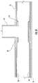
- FIG. 1is a sectional view of an embodiment of the invention showing the assembly being pulled into place at the intersection of a main pipe line and a lateral pipe line.
- FIG. 2is a sectional view of the embodiment shown in FIG. 1 wherein access has been restored to the lateral pipe line.
- FIG. 4is a sectional view of the embodiment shown in FIG. 3 showing the assembly being inverted into the main pipe line across an opening that is the junction between two pipes.
- FIG. 5is a sectional view of the embodiment shown in FIGS. 3 and 4 showing the assembly positioned over the opening, which is an intersection of the main pipe line and the lateral pipe line.
- FIG. 6is a sectional view of an embodiment showing the sealing member positioned between the preliner and the mainline liner.
- FIG. 7is a perspective view of an embodiment where the sealing member is a tubular sleeve.
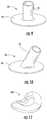
- FIG. 9is a perspective view of an embodiment where the sealing member is a brim-style junction liner configured for installation at a tee junction prior to installation within a pipe.
- FIG. 10is a perspective view of an embodiment where the sealing member is a brim-style junction liner configured for installation at a wye junction prior to installation within a pipe.
- FIG. 11is a perspective view of an embodiment where the sealing member is a ring-shaped gasket.
- FIG. 12is a sectional view of an embodiment where the sealing member is a ring-shaped gasket positioned around the junction between the main pipe line and the lateral pipe line.
- FIG. 13is a sectional view of an embodiment where the sealing member is the preliner.
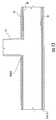
- FIG. 14is a sectional view of an embodiment wherein the sealing member is combined with the mainline liner (and no separate preliner is used).
- FIG. 15is a sectional view of an embodiment showing the assembly positioned at the junction of the main pipe line and the lateral pipe line.
- FIG. 16is a sectional view of an embodiment where access has been restored to the lateral pipe line.
- FIGS. 1 and 2show a first embodiment of the invention wherein an assembly is provided for helping to repair an opening in a pipe.
- the openingmay be a damaged/cracked section in a length of pipe or it may be the junction between a main pipe and a lateral pipe.
- FIGS. 1 and 2 and the following embodimentswill be described primarily with reference to embodiments where the opening is the junction of a first pipe and a second pipe.
- the first and second pipesmay be a main pipe line 12 and a lateral pipe line 14 .
- the assemblyincludes a sealing member 10 attached to a positioning tube such as preliner 16 which carries the sealing member 10 through the main pipe line 12 to its desired position at the main/lateral pipe junction.
- the sealing member 10is attached to the preliner 16 by stitching, stapling, by use of an adhesive or other suitable attachment means.
- the assemblyfurther includes a liner 20 positioned inside the preliner 16 as described below in more detail.
- the preliner 16is formed of a moisture impervious polymer material and may be thermoplastic, polyurethane, polyvinyl chloride, polyethylene or other similar material.
- the sealing member 10may be made from or impregnated with a hydrophilic or hydrophobic material.
- the sealing member 10may be a single, unitary piece that may be made by vulcanization processes. Such methods include wrapping or extruding polymeric material around a mandrel and placing the loaded mandrel into a vulcanizing autoclave for a predetermined period of time. A vulcanization method is preferred for the sealing member 10 , because the material may be formed in a tube of considerable length to be cut into shorter sealing members. Such a method would decrease the cost of producing the sealing-member 10 compared to other methods, allowing for the simultaneous production of a plurality of units. Other methods of forming the sealing member 10 include casting or molding methods, including but not limited to resin casting, injection molding, blow molding, or extrusion molding.
- the sealing member 10is less than about ten millimeters in thickness. In other embodiments the sealing member 10 is two-three millimeters thick. In embodiments where the sealing member 10 is a tubular sleeve, the sleeve is preferably produced directly in the form of a tube. However, it should also be appreciated that alternative constructions of a tube are possible, such as where a sheet of material is formed into a tube and fused together by thermal bonding, sewing, adhesives, or other mechanical bonding methods. It should also be noted that the sealing member 10 may be formed by taking a sheet of material and forming it into a tube by overlapping the ends, and then securing the tubular form within the pipe.
- the sealing member 10preferably comprises a generally uniform wall thickness along the length of the sealing member. It should also be noted that the sealing member 10 may have a non-tubular configuration as described below in more detail.
- the sealing member 10is combined with the preliner 16 so that when the assembly is positioned in the main pipe 12 , the sealing member 10 corresponds with the lateral pipe junction as shown in FIGS. 1 and 5 .
- the assemblyincludes more than one sealing member 10 attached to the preliner 16 adapted to be positioned over more than one corresponding lateral pipe junction within a single main pipe line 12 .
- the sealing member 10has a tubular shape and surrounds the preliner 16 .
- the sealing member 10is sized such that it extends along the main pipe 12 on opposite sides of the lateral pipe junction.
- the sealing member 10would be eight or ten inches long to allow a portion of the sealing member 10 to contact the main pipe 12 on either side of the lateral pipe 14 opening. Also, in this embodiment the sealing member 10 would be sized to approximate the diameter of the main pipe.
- the assemblyis positioned in the main pipe 12 by any suitable method.
- the assemblyis pulled into place by pulling on a rope 18 that is attached to an end of the assembly or by using a positioning device, such as a robot.
- the assemblyis inverted into the main pipe 12 from a manhole or launcher device 24 .
- FIG. 3shows a length of main pipe line 12 that separates the launcher device 24 from a lateral pipe junction. The distance between the launcher device 24 and the lateral pipe 14 is determined then the sealing member 10 is attached to the interior of the preliner 16 so that upon inversion the preliner has extended the appropriate distance from the launcher 24 to locate the sealing member 10 across the lateral pipe 14 opening.
- FIG. 4shows the preliner 16 and sealing member 10 partially inverted
- FIG. 5shows the sealing member 10 fully inverted across the lateral pipe 14 opening so that at least a portion of the sealing member 10 is positioned on opposite sides of the lateral pipe 14 .
- a mainline liner 20is installed with the preliner 16 between the host pipe and the new mainline liner 20 . This is shown in FIGS. 1 and 2 wherein the preliner 16 and sealing member 10 are positioned in the pipe 12 ( FIG. 1 ). The liner 20 is then installed inside the preliner 16 ( FIG. 2 ) so that the preliner 16 is between the sealing member 10 and the liner 20 . Any suitable liner 20 may be used. In some embodiments the liner 20 is a resin impregnated cured-in-place liner that is pulled or inverted into position within the preliner 16 .
- the liner 20is a folded liner or a spray-on liner.
- the liner 20may be fluidly sealed on its ends and have a fluid-impermeable coating on one side, allowing it to be installed under pressure using a fluid pressure source without the use of a bladder.
- the inflationexpands the assembly toward the walls of the pipe 12 and helps hold the assembly against the walls of the pipe 12 as the impregnated liner 20 cures and hardens.
- Other embodimentsfurther include positioning a bladder assembly inside the liner 20 and then inflating the bladder assembly to help press the components against the wall of the pipe 12 .
- a cutteris used to cut an opening in the mainline liner 20 , preliner 16 , and sealing member 10 to reinstate service to the lateral pipe.
- the sealing member 10remains in place around the periphery of the lateral pipe 14 junction to act as a water stop at the main/lateral junction.
- preliner 16 and sealing member 10may be positioned in the pipe 12 along with the liner in a single step.
- FIG. 6shows an alternate embodiment wherein the sealing member 10 is attached to the preliner 16 so that the sealing member 10 is between the preliner 16 and the mainline liner 20 after it is positioned in the pipe 12 .
- the sealing member 10is attached to the other side of the preliner 16 .
- FIGS. 7-11show various embodiments of the sealing member 10 . While reference number 10 is used to generally refer to any sealing member throughout this disclosure, some specific embodiments are referred to with reference numbers 10 a - 10 d .
- FIGS. 7 and 8show an embodiment where the sealing member 10 a is a tubular sleeve.
- the sealing member 10may be a tubular sleeve that is constructed of or impregnated with a hydrophilic or hydrophobic material.
- the sealing member 10 ais a hydrophilic neoprene rubber having a hardness of less than 90 Shore A Durometer Scale.
- the hydrophilic materialmay be such that the sealing member 10 a is collapsible, as shown in FIG.
- the tubular sleeve 10 amay include a flange attached to at least a portion of an end thereof.
- the sealing member 10 amay be used in embodiments where the assembly includes a sealing member 10 and a liner assembly 20 (but no preliner 16 ).
- the sealing member 10 amay be rigid enough to retain its shape and position within the main pipe 12 before the liner 20 is installed.
- a mechanical fastener 38such as a metal ring adapted to retain the sealing member 10 against a wall of the pipe 12 before the liner 20 is positioned over the sealing member 10 a .
- the sealing member 10 ais positioned at the pipe junction by a robot or manually if the pipe is large enough to accommodate a person.
- an inflatable packercould carry the sealing member 10 a with a mechanical fastener 38 that is a stainless steel ring having ratchets. When the packer is inflated, the ring 38 would expand and lock in place to support the hydrophilic sealing member 10 a . Then, the mainline liner 20 is installed as described above with the sealing member 10 a between the host pipe 12 and the new mainline liner 20 as shown in FIG.
- a cutteris used to cut an opening in the mainline liner 20 , preliner 16 , and sealing member 10 a to reinstate service to the lateral pipe as shown in FIG. 16 .
- the sealing member 10 aremains in place around the junction of the lateral pipe 14 junction to act as a water stop at the main/lateral junction.
- FIGS. 9 and 10show an embodiment where the sealing member 10 b , 10 c is a brim-style junction liner having a flange member combined with a tubular member to generally form the shape of a top hat.
- the brim-style junction lineradapted to be placed at a main/lateral pipe junction with the flange portion adapted to be positioned in the main pipe 12 and the tubular portion adapted to be placed in the lateral pipe 14 .
- FIG. 9shows an embodiment where the sealing member 10 b is a brim-style junction liner configured for installation at a tee junction prior to installation within a pipe.
- FIG. 10shows an embodiment where the sealing member 10 c is a brim-style junction liner configured for installation at a wye junction prior to installation within a pipe.
- FIGS. 11 and 12show an embodiment where the sealing member 10 d is ring or disc-shaped with an aperture through the center.
- the sealing member 10 ddoes not extend around the full circumference of the preliner 16 . Instead, the sealing member 10 d is adapted to only surround the lateral pipe 14 opening at the main/lateral junction.
- the sealing member 10 dis attached to the preliner 16 by any suitable means, including with clips, snaps, adhesive, etc.
- FIG. 12shows an embodiment where there are existing openings/cracks in the pipeline wall.
- the sealing member 10is an open cell material impregnated with a hydrophilic or hydrophobic material such as a hydrophilic or hydrophobic chemical paste or grout.
- the sealing member 10is used as a carrier to transport the liquid grout material to a pipe juncture. All or nearly all of the liquid grout material is expelled from the sealing member 10 when pressed toward the pipe 12 leaving the sealing member with minimal thickness. In this manner the grout material penetrates through the damaged portion of the junction between the main pipe 12 and the lateral pipe 14 and to an area in the soil surrounding the pipe junction.
- the sealing member 10is attached to the preliner 16 before being impregnated with the hydrophilic or hydrophobic material. As with the embodiments discussed above, a resin impregnated liner 20 is positioned inside the preliner 16 .
- the sealing member shown in FIG. 12is sealing member 10 d shown in FIG. 11 ; however, any suitable sealing member 10 may be used.
- FIG. 13shows an embodiment where the preliner 16 is also the sealing member 10 .
- FIG. 13shows this component having both reference numbers 10 and 16 .
- the preliner 10 , 16is adapted to be positioned in the main pipe 12 .
- the preliner 10 , 16is formed from a hydrophilic or hydrophobic material such as a hydrophilic or hydrophobic rubber or thermoplastic that is hydrophilic or hydrophobic.
- there is no need for a separate sealing member 10because the preliner 10 , 16 is at least partially made from sealing member 10 material.
- the preliner 10 , 16is pulled in place or inverted into the main pipe liner so that it covers one or more lateral pipe junctions.
- the mainline liner 20is pulled or inverted into place inside of the preliner 10 , 16 after the preliner 10 , 16 has been positioned.
- the preliner 10 , 16 and mainline liner 20are pulled or inverted into place at the same time in a single step. After the liner 20 cures and hardens, a cutter is used to reinstate service to the lateral pipe 14 .
- the preliner 10 , 16remains in place to act as a water stop at the main/lateral junction.
- FIG. 14shows an embodiment that is similar to the other embodiments, except the mainline liner 20 is used as the positioning tube instead of a preliner 16 .
- the liner 20has an exterior surface which includes an impermeable coating such as a plastic.
- the sealing member 10is attached directly to the exterior surface of the liner 20 either before or after the liner 20 is impregnated with resin.
- the liner 20is pulled into place within the pipeline 12 to locate the sealing member 10 at the main/lateral pipe junction.
- a bladder assemblymay be positioned and inflated inside the liner 20 to help press the other components against the wall of the pipe 12 .
- the methods for using the assemblies described aboveinclude attaching the sealing member 10 to the preliner 16 then placing the preliner 16 and sealing member 10 in the main pipe 12 using pull-in-place or inversion methods.
- the sealing member 10is aligned with the lateral pipe junction so that at least a portion of the sealing member 10 extends along the main pipe 12 on either side of the lateral pipe 14 opening.
- the mainline liner 20is impregnated with resin and positioned in the main pipe 12 and pressed toward an inner wall of the main pipe 12 so that the sealing member is between the liner 20 and the pipe 12 wall as shown in FIG. 15 .
- the sealing member 10may be attached to either side of the preliner 16 resulting in the sealing member 10 being between the preliner 16 and the wall of the main pipe 12 or the sealing member 10 being between the liner 20 and the preliner 16 .
- the mainline liner 20may be pressed toward the inner wall of the main pipe 12 using an inflatable bladder assembly or without using a bladder as disclosed in U.S. Pat. No. 7,845,372 (Kiest), which is incorporated by reference.
- a cutteris used to cut an opening in the mainline liner 20 , preliner 16 , and sealing member 10 to reinstate service to the lateral pipe as shown in FIG. 16 .
- the sealing member 10remains in place to act as a water stop at the main/lateral junction.
- FIGS. 1-8 and 13-16may be used to repair an opening that is a crack or hole in a length of pipe.
- the descriptions of the methods and assemblies for these figuresapply to repairing an opening that is a crack or hole along a length of pipe, except that when repairing an opening that is a crack or hole along a length of pipe the sealing member corresponds with and extends across the crack or hole in the pipe instead of across the junction between two pipes.
- a cutteris not used to cut through layers of the assembly since the repair occurs along a length of pipe and not at a pipe junction requiring reinstatement of lateral pipe access.
Landscapes
- Engineering & Computer Science (AREA)
- General Engineering & Computer Science (AREA)
- Mechanical Engineering (AREA)
- Chemical & Material Sciences (AREA)
- Combustion & Propulsion (AREA)
- Lining Or Joining Of Plastics Or The Like (AREA)
- Pipe Accessories (AREA)
Abstract
Description
Claims (28)
Priority Applications (3)
| Application Number | Priority Date | Filing Date | Title |
|---|---|---|---|
| US15/785,622US10683959B2 (en) | 2017-10-17 | 2017-10-17 | Method and apparatus for repairing a length of pipe or a main/lateral pipe junction |
| CA3079217ACA3079217A1 (en) | 2017-10-17 | 2018-10-17 | Method and apparatus for repairing a length of pipe or a main/lateral pipe junction |
| PCT/US2018/056184WO2019079370A1 (en) | 2017-10-17 | 2018-10-17 | Method and apparatus for repairing a length of pipe or a main/lateral pipe junction |
Applications Claiming Priority (1)
| Application Number | Priority Date | Filing Date | Title |
|---|---|---|---|
| US15/785,622US10683959B2 (en) | 2017-10-17 | 2017-10-17 | Method and apparatus for repairing a length of pipe or a main/lateral pipe junction |
Publications (2)
| Publication Number | Publication Date |
|---|---|
| US20190113168A1 US20190113168A1 (en) | 2019-04-18 |
| US10683959B2true US10683959B2 (en) | 2020-06-16 |
Family
ID=66095726
Family Applications (1)
| Application Number | Title | Priority Date | Filing Date |
|---|---|---|---|
| US15/785,622Active2038-02-01US10683959B2 (en) | 2017-10-17 | 2017-10-17 | Method and apparatus for repairing a length of pipe or a main/lateral pipe junction |
Country Status (3)
| Country | Link |
|---|---|
| US (1) | US10683959B2 (en) |
| CA (1) | CA3079217A1 (en) |
| WO (1) | WO2019079370A1 (en) |
Cited By (1)
| Publication number | Priority date | Publication date | Assignee | Title |
|---|---|---|---|---|
| US20230007987A1 (en)* | 2020-04-03 | 2023-01-12 | Origin Tech Ltd | A method of inhibiting leakage of a fluid through a defect in a wall of a pipe |
Families Citing this family (3)
| Publication number | Priority date | Publication date | Assignee | Title |
|---|---|---|---|---|
| WO2020072658A1 (en)* | 2018-10-05 | 2020-04-09 | Lmk Technologies Llc | Method and assembly for sealing off a pipe |
| US11649601B2 (en)* | 2020-04-08 | 2023-05-16 | Ina Acquisition Corp. | Method and apparatus for installing end seals |
| US11643801B1 (en)* | 2021-12-29 | 2023-05-09 | Gulf Coast Underground, LLC | System and method for sealing an annular space of a sewer connection line |
Citations (69)
| Publication number | Priority date | Publication date | Assignee | Title |
|---|---|---|---|---|
| US1861726A (en) | 1927-02-16 | 1932-06-07 | Chester A Rasmussen | Blow-out preventer |
| US3773593A (en) | 1971-03-25 | 1973-11-20 | Martin Marietta Corp | Method of making hot gas manifold |
| US3781966A (en) | 1972-12-04 | 1974-01-01 | Whittaker Corp | Method of explosively expanding sleeves in eroded tubes |
| US3894131A (en) | 1972-05-18 | 1975-07-08 | Minnesota Mining & Mfg | Poly(urethane-urea) sealants and sealing underground structures therewith |
| US4522432A (en) | 1982-04-21 | 1985-06-11 | Umc Industries, Inc. | Components for lined piping system with anchored liners and method of manufacture |
| EP0506181A1 (en) | 1991-03-26 | 1992-09-30 | Wavin B.V. | Method for lining from the inside a connection between a main pipe and a branch pipe, using an expandable sleeve of hardenable material, and a sleeve suitable for the purpose |
| US5167258A (en)* | 1987-11-06 | 1992-12-01 | Nigel Rice | Re-lining of sewers |
| EP0564741A1 (en) | 1992-04-07 | 1993-10-13 | Ashimori Industry Co., Ltd. | Method and apparatus for repairing a pipeline |
| US5340160A (en) | 1989-11-21 | 1994-08-23 | Wavin B.V. | Thermoplastic saddle in two parts for repairing or renovating a pipe line with branch pipe and repaired or renovated pipe with a saddle |
| US5368075A (en) | 1990-06-20 | 1994-11-29 | Abb Reaktor Gmbh | Metallic sleeve for bridging a leakage point on a pipe |
| US5393481A (en) | 1990-04-23 | 1995-02-28 | Insituform (Netherlands) Bv | Lining of pipelines or passageways |
| US5411060A (en)* | 1992-04-03 | 1995-05-02 | Chandler; Brian | Composite pipe |
| US5474823A (en) | 1993-04-13 | 1995-12-12 | Shonan Gosei-Jushi Seisakusho K.K. | Pipe liner bag, manufacturing method therefor and pipe repair method |
| DE4421290A1 (en) | 1994-06-17 | 1995-12-21 | Hans Dipl Ing Dammer | Process for sealing of leaks in esp. sewer pipes |
| US5511573A (en) | 1994-10-24 | 1996-04-30 | K N Energy, Inc. | Contaminated valve containment device |
| US5566719A (en) | 1994-07-05 | 1996-10-22 | Shonan Gosei-Jushi Seisakusho K.K. | Method for lining a branch pipe of an underground pipe |
| US5587126A (en) | 1986-03-31 | 1996-12-24 | Nupipe, Inc. | Method of manufacturing a pipe liner for installation in an existing conduit |
| US5609439A (en) | 1992-03-06 | 1997-03-11 | Kmg Kanal-Muller-Gruppe International Gmbh & Co. Kg | Method of and apparatus for repairing and sealing junctions between mains and branch pipes |
| US5738146A (en) | 1996-02-16 | 1998-04-14 | Sekishin Sangyo Co., Ltd. | Method for rehabilitation of underground piping |
| US5765597A (en) | 1994-08-19 | 1998-06-16 | Kiest, Jr.; Larry W. | Apparatus for repairing a pipeline and method for using same |
| US5794663A (en) | 1994-08-19 | 1998-08-18 | Lmk Enterprises | Apparatus for repairing a pipeline and method for using same |
| US5879501A (en) | 1996-12-19 | 1999-03-09 | Illinois Tool Works, Inc. | Method of sealing sewer systems |
| US5916406A (en) | 1996-02-14 | 1999-06-29 | Shonan Gosei-Jushi Seisakusho Kk | Branch pipe liner bag and pipe lining method |
| US5915419A (en) | 1997-11-26 | 1999-06-29 | Insituform (Netherlands) B.V. | Cured in place lateral seal for relining of pipelines and method of manufacture |
| US5924436A (en) | 1997-04-11 | 1999-07-20 | Waterworks Technology Development Organization Co., Ltd. | Connecting construction of branch pipe and connecting method thereof |
| US5927341A (en) | 1993-09-25 | 1999-07-27 | Insituform (Netherlands) B.V. | Lining of "Tees" and "Wyes" in pipelines or passageways |
| US5944058A (en) | 1997-02-04 | 1999-08-31 | Shonan Gosei-Jushi Seisakusho K.K. | Branch pipe liner assembly and a pipe lining method |
| US5950682A (en) | 1994-08-19 | 1999-09-14 | Lmk Enterprises, Inc. | Apparatus and method for repairing the junction of a sewer main line and lateral |
| US5971032A (en) | 1998-11-20 | 1999-10-26 | Tele Environmental Systems | Apparatus and method for the robotic repairing of an underground pipe junction |
| US6031371A (en) | 1995-05-22 | 2000-02-29 | Bg Plc | Self-powered pipeline vehicle for carrying out an operation on a pipeline and method |
| US6039079A (en) | 1998-07-17 | 2000-03-21 | Lmk Enterprises, Inc. | Apparatus and method for repairing the junction of a sewer main line and lateral pipe |
| US6068725A (en) | 1997-11-26 | 2000-05-30 | Insituform (Netherlands) B.V. | Method of installation of a flexible cured in place lateral seal in an existing main pipeline |
| US6101951A (en) | 1997-01-10 | 2000-08-15 | Scheiff Gmbh | Robot for the repair of sewer pipes |
| US6123109A (en) | 1997-02-04 | 2000-09-26 | Shonan Gosei-Jushi Seisakusho K.K. | Branch pipe lining bag and pipe lining method |
| US6158473A (en) | 1998-08-06 | 2000-12-12 | Shonan Gosei-Jushi Seisakusho K.K. | Branch pipe liner bag and pipe lining method |
| EP1070902A2 (en) | 1999-07-22 | 2001-01-24 | Etex | Branch pipe and method of manufacturing the same |
| JP2001269998A (en) | 2000-03-28 | 2001-10-02 | Iseki Poly-Tech Inc | Lining method for existing sewer and lateral |
| US6328310B1 (en) | 1999-02-03 | 2001-12-11 | Acacia Kakou Co., Ltd. | Method of preventing water leakage with waterproof seal |
| US6337114B1 (en) | 1992-09-10 | 2002-01-08 | Insituform (Netherlands) B.V. | Flexible lining with flexible collar for lining lateral pipelines |
| US6416692B1 (en) | 2000-03-10 | 2002-07-09 | Jeffrey L. Iwasaki-Higbee | Sewer system pipe repairs |
| US6541106B1 (en) | 2000-09-12 | 2003-04-01 | The United States Of America As Represented By The Secretary Of The Interior | Hydrophilic polyurethane impregnated rubber for sealing water leaks |
| US6641688B1 (en) | 2001-03-30 | 2003-11-04 | Stephen V. Gearhart | Method for sealing an annular space |
| US6651699B2 (en) | 2001-12-12 | 2003-11-25 | Tae-Joo Kweon | Liner for branch pipe of old repaired pipe and lining system and method for such liner |
| US6688337B2 (en) | 2001-12-19 | 2004-02-10 | Robert M. Ward | Apparatus and method for the robotic repairing of an underground pipe junction with a flexible patch mechanism |
| EP1447610A1 (en) | 2003-02-14 | 2004-08-18 | RS Technik AG | Device for establishing an inner lining in a conduit and a jacket hose containing the lining hose |
| US6994118B2 (en) | 2003-12-04 | 2006-02-07 | Blue Sky Forever, Inc. | Device and method for repairing pipe using hydrophilic seals |
| US7028716B2 (en) | 2004-05-28 | 2006-04-18 | Shonan Gosei-Jushi Seisakusho K.K. | Method for rehabilitating an existing pipe |
| US7131791B2 (en) | 2002-11-13 | 2006-11-07 | Redzone Robotics, Inc. | Pipeline rehabilitation systems |
| US20070137785A1 (en) | 2005-12-17 | 2007-06-21 | Brandenburger Patentverwertung Gdbr | Method for the renovation of branch lines of conduit pipes |
| US7311121B2 (en) | 2004-10-27 | 2007-12-25 | Shonan Gosei-Jushi Seisakusho K.K. | Lateral pipe lining material and lateral pipe lining method |
| US7398797B2 (en) | 2006-04-14 | 2008-07-15 | Shonan Gosei-Jushi Seisakusho K.K. | Pipe lining method |
| US7481246B2 (en) | 2006-08-03 | 2009-01-27 | Shonan Gosei-Jushi Seisakusho K.K. | Lateral pipe lining material and lateral pipe lining method |
| US20090056823A1 (en)* | 2007-08-27 | 2009-03-05 | Lmk Enterprises, Inc. | Device and method for repairing pipe |
| US7670086B2 (en) | 2005-11-23 | 2010-03-02 | Lmk Enterprises, Inc. | Method of repairing a manhole chimney using a stretchable sleeve |
| US7720570B2 (en) | 2004-10-01 | 2010-05-18 | Redzone Robotics, Inc. | Network architecture for remote robot with interchangeable tools |
| US7849883B2 (en) | 2005-05-02 | 2010-12-14 | Nuflow Technologies 2000 Inc. | Liner assembly for pipeline repair and methods of installing same |
| CA2674984A1 (en) | 2009-08-07 | 2011-02-07 | Fer-Pal Construction Ltd. | Methods for rehabilitating conduits using structural liners |
| US7987873B2 (en) | 2008-02-06 | 2011-08-02 | Lmk Enterprises, Inc. | Device and method for repairing pipe |
| US20110203719A1 (en)* | 2010-02-22 | 2011-08-25 | Lmk Enterprises, Inc. | Apparatus and method to repair the junction of a sewer main line and lateral pipe |
| US20120175004A1 (en)* | 2011-01-10 | 2012-07-12 | Lmk Enterprises, Inc. | Liner tube with non-stretching material |
| US8240340B2 (en) | 2010-12-07 | 2012-08-14 | Lmk Enterprises, Inc. | Hydrophilic end seal |
| US8240341B2 (en) | 2010-12-07 | 2012-08-14 | Lmk Enterprises, Inc. | Hydrophilic end seal |
| US8316892B2 (en) | 2007-04-03 | 2012-11-27 | Liqui-Force Sewer Services Inc. | Lateral liner with seal |
| US8640737B2 (en) | 2010-12-07 | 2014-02-04 | Lmk Technologies, Llc | Apparatus and method for sealing pipes and underground structures |
| US20140121324A1 (en)* | 2012-10-25 | 2014-05-01 | Buergofol GmbH | Mono- or Multi-Layer Film |
| US20170028668A1 (en)* | 2014-04-09 | 2017-02-02 | Buergofol GmbH | Polymeric Multilayer Film |
| US20170146178A1 (en) | 2015-11-10 | 2017-05-25 | Lmk Technologies, Llc | Method and Apparatus for Repairing a Pipe Junction |
| US9714735B2 (en)* | 2014-05-27 | 2017-07-25 | LMK Technologies, Inc. | Method of repairing a manhole and pipes |
| US9791089B2 (en) | 2012-03-23 | 2017-10-17 | Lmk Technologies, Llc | Method and apparatus for repairing a pipe junction |
- 2017
- 2017-10-17USUS15/785,622patent/US10683959B2/enactiveActive
- 2018
- 2018-10-17CACA3079217Apatent/CA3079217A1/enactivePending
- 2018-10-17WOPCT/US2018/056184patent/WO2019079370A1/ennot_activeCeased
Patent Citations (78)
| Publication number | Priority date | Publication date | Assignee | Title |
|---|---|---|---|---|
| US1861726A (en) | 1927-02-16 | 1932-06-07 | Chester A Rasmussen | Blow-out preventer |
| US3773593A (en) | 1971-03-25 | 1973-11-20 | Martin Marietta Corp | Method of making hot gas manifold |
| US3894131A (en) | 1972-05-18 | 1975-07-08 | Minnesota Mining & Mfg | Poly(urethane-urea) sealants and sealing underground structures therewith |
| US3781966A (en) | 1972-12-04 | 1974-01-01 | Whittaker Corp | Method of explosively expanding sleeves in eroded tubes |
| US4522432A (en) | 1982-04-21 | 1985-06-11 | Umc Industries, Inc. | Components for lined piping system with anchored liners and method of manufacture |
| US5587126A (en) | 1986-03-31 | 1996-12-24 | Nupipe, Inc. | Method of manufacturing a pipe liner for installation in an existing conduit |
| US5167258A (en)* | 1987-11-06 | 1992-12-01 | Nigel Rice | Re-lining of sewers |
| US5340160A (en) | 1989-11-21 | 1994-08-23 | Wavin B.V. | Thermoplastic saddle in two parts for repairing or renovating a pipe line with branch pipe and repaired or renovated pipe with a saddle |
| US6899832B2 (en) | 1990-04-23 | 2005-05-31 | Insituform (Netherlands) B.V. | Installation of flexible lining with flexible collar for lining lateral pipelines |
| US5393481A (en) | 1990-04-23 | 1995-02-28 | Insituform (Netherlands) Bv | Lining of pipelines or passageways |
| US5368075A (en) | 1990-06-20 | 1994-11-29 | Abb Reaktor Gmbh | Metallic sleeve for bridging a leakage point on a pipe |
| EP0506181A1 (en) | 1991-03-26 | 1992-09-30 | Wavin B.V. | Method for lining from the inside a connection between a main pipe and a branch pipe, using an expandable sleeve of hardenable material, and a sleeve suitable for the purpose |
| US5609439A (en) | 1992-03-06 | 1997-03-11 | Kmg Kanal-Muller-Gruppe International Gmbh & Co. Kg | Method of and apparatus for repairing and sealing junctions between mains and branch pipes |
| US5411060A (en)* | 1992-04-03 | 1995-05-02 | Chandler; Brian | Composite pipe |
| EP0564741A1 (en) | 1992-04-07 | 1993-10-13 | Ashimori Industry Co., Ltd. | Method and apparatus for repairing a pipeline |
| US6337114B1 (en) | 1992-09-10 | 2002-01-08 | Insituform (Netherlands) B.V. | Flexible lining with flexible collar for lining lateral pipelines |
| US5474823A (en) | 1993-04-13 | 1995-12-12 | Shonan Gosei-Jushi Seisakusho K.K. | Pipe liner bag, manufacturing method therefor and pipe repair method |
| US5927341A (en) | 1993-09-25 | 1999-07-27 | Insituform (Netherlands) B.V. | Lining of "Tees" and "Wyes" in pipelines or passageways |
| DE4421290A1 (en) | 1994-06-17 | 1995-12-21 | Hans Dipl Ing Dammer | Process for sealing of leaks in esp. sewer pipes |
| US5566719A (en) | 1994-07-05 | 1996-10-22 | Shonan Gosei-Jushi Seisakusho K.K. | Method for lining a branch pipe of an underground pipe |
| US5794663A (en) | 1994-08-19 | 1998-08-18 | Lmk Enterprises | Apparatus for repairing a pipeline and method for using same |
| US6021815A (en) | 1994-08-19 | 2000-02-08 | Lmk Enterprises | Method for preparing a repair assembly for pipe repair |
| US6199591B1 (en) | 1994-08-19 | 2001-03-13 | Lmk Enterprises | Method of using detachable lines for positioning pipeline repair liner |
| US6641687B2 (en) | 1994-08-19 | 2003-11-04 | Lmk Enterprises | Apparatus for repairing a pipeline and method for using same |
| US6105619A (en) | 1994-08-19 | 2000-08-22 | Lmk Enterprises, Inc. | Apparatus for repairing a pipeline and method for using same |
| US5765597A (en) | 1994-08-19 | 1998-06-16 | Kiest, Jr.; Larry W. | Apparatus for repairing a pipeline and method for using same |
| US5950682A (en) | 1994-08-19 | 1999-09-14 | Lmk Enterprises, Inc. | Apparatus and method for repairing the junction of a sewer main line and lateral |
| US5511573A (en) | 1994-10-24 | 1996-04-30 | K N Energy, Inc. | Contaminated valve containment device |
| US6031371A (en) | 1995-05-22 | 2000-02-29 | Bg Plc | Self-powered pipeline vehicle for carrying out an operation on a pipeline and method |
| US5916406A (en) | 1996-02-14 | 1999-06-29 | Shonan Gosei-Jushi Seisakusho Kk | Branch pipe liner bag and pipe lining method |
| US5738146A (en) | 1996-02-16 | 1998-04-14 | Sekishin Sangyo Co., Ltd. | Method for rehabilitation of underground piping |
| US5879501A (en) | 1996-12-19 | 1999-03-09 | Illinois Tool Works, Inc. | Method of sealing sewer systems |
| US6101951A (en) | 1997-01-10 | 2000-08-15 | Scheiff Gmbh | Robot for the repair of sewer pipes |
| US6123109A (en) | 1997-02-04 | 2000-09-26 | Shonan Gosei-Jushi Seisakusho K.K. | Branch pipe lining bag and pipe lining method |
| US5944058A (en) | 1997-02-04 | 1999-08-31 | Shonan Gosei-Jushi Seisakusho K.K. | Branch pipe liner assembly and a pipe lining method |
| US5924436A (en) | 1997-04-11 | 1999-07-20 | Waterworks Technology Development Organization Co., Ltd. | Connecting construction of branch pipe and connecting method thereof |
| US6068725A (en) | 1997-11-26 | 2000-05-30 | Insituform (Netherlands) B.V. | Method of installation of a flexible cured in place lateral seal in an existing main pipeline |
| US6044867A (en) | 1997-11-26 | 2000-04-04 | Insituform (Netherlands) N.V. | Method and apparatus for fabricating a flexible lining with flexible collar for lining lateral pipelines |
| US5915419A (en) | 1997-11-26 | 1999-06-29 | Insituform (Netherlands) B.V. | Cured in place lateral seal for relining of pipelines and method of manufacture |
| US6039079A (en) | 1998-07-17 | 2000-03-21 | Lmk Enterprises, Inc. | Apparatus and method for repairing the junction of a sewer main line and lateral pipe |
| US6158473A (en) | 1998-08-06 | 2000-12-12 | Shonan Gosei-Jushi Seisakusho K.K. | Branch pipe liner bag and pipe lining method |
| US5971032A (en) | 1998-11-20 | 1999-10-26 | Tele Environmental Systems | Apparatus and method for the robotic repairing of an underground pipe junction |
| US6328310B1 (en) | 1999-02-03 | 2001-12-11 | Acacia Kakou Co., Ltd. | Method of preventing water leakage with waterproof seal |
| EP1070902A2 (en) | 1999-07-22 | 2001-01-24 | Etex | Branch pipe and method of manufacturing the same |
| US6416692B1 (en) | 2000-03-10 | 2002-07-09 | Jeffrey L. Iwasaki-Higbee | Sewer system pipe repairs |
| JP2001269998A (en) | 2000-03-28 | 2001-10-02 | Iseki Poly-Tech Inc | Lining method for existing sewer and lateral |
| US6541106B1 (en) | 2000-09-12 | 2003-04-01 | The United States Of America As Represented By The Secretary Of The Interior | Hydrophilic polyurethane impregnated rubber for sealing water leaks |
| US7094308B1 (en) | 2001-03-30 | 2006-08-22 | Gearhart Stephen V | Method for sealing an annular space |
| US6641688B1 (en) | 2001-03-30 | 2003-11-04 | Stephen V. Gearhart | Method for sealing an annular space |
| US6651699B2 (en) | 2001-12-12 | 2003-11-25 | Tae-Joo Kweon | Liner for branch pipe of old repaired pipe and lining system and method for such liner |
| US6688337B2 (en) | 2001-12-19 | 2004-02-10 | Robert M. Ward | Apparatus and method for the robotic repairing of an underground pipe junction with a flexible patch mechanism |
| US7131791B2 (en) | 2002-11-13 | 2006-11-07 | Redzone Robotics, Inc. | Pipeline rehabilitation systems |
| EP1447610A1 (en) | 2003-02-14 | 2004-08-18 | RS Technik AG | Device for establishing an inner lining in a conduit and a jacket hose containing the lining hose |
| US6994118B2 (en) | 2003-12-04 | 2006-02-07 | Blue Sky Forever, Inc. | Device and method for repairing pipe using hydrophilic seals |
| US7028716B2 (en) | 2004-05-28 | 2006-04-18 | Shonan Gosei-Jushi Seisakusho K.K. | Method for rehabilitating an existing pipe |
| US7720570B2 (en) | 2004-10-01 | 2010-05-18 | Redzone Robotics, Inc. | Network architecture for remote robot with interchangeable tools |
| US7311121B2 (en) | 2004-10-27 | 2007-12-25 | Shonan Gosei-Jushi Seisakusho K.K. | Lateral pipe lining material and lateral pipe lining method |
| US7849883B2 (en) | 2005-05-02 | 2010-12-14 | Nuflow Technologies 2000 Inc. | Liner assembly for pipeline repair and methods of installing same |
| US7670086B2 (en) | 2005-11-23 | 2010-03-02 | Lmk Enterprises, Inc. | Method of repairing a manhole chimney using a stretchable sleeve |
| US8721216B2 (en) | 2005-11-23 | 2014-05-13 | Lmk Enterprises, Inc. | Method of repairing a manhole chimney using a stretchable sleeve |
| US20070137785A1 (en) | 2005-12-17 | 2007-06-21 | Brandenburger Patentverwertung Gdbr | Method for the renovation of branch lines of conduit pipes |
| US7398797B2 (en) | 2006-04-14 | 2008-07-15 | Shonan Gosei-Jushi Seisakusho K.K. | Pipe lining method |
| US7481246B2 (en) | 2006-08-03 | 2009-01-27 | Shonan Gosei-Jushi Seisakusho K.K. | Lateral pipe lining material and lateral pipe lining method |
| US8316892B2 (en) | 2007-04-03 | 2012-11-27 | Liqui-Force Sewer Services Inc. | Lateral liner with seal |
| US20090056823A1 (en)* | 2007-08-27 | 2009-03-05 | Lmk Enterprises, Inc. | Device and method for repairing pipe |
| US7975726B2 (en) | 2007-08-27 | 2011-07-12 | Lmk Enterprises, Inc. | Device and method for repairing pipe |
| US7987873B2 (en) | 2008-02-06 | 2011-08-02 | Lmk Enterprises, Inc. | Device and method for repairing pipe |
| CA2674984A1 (en) | 2009-08-07 | 2011-02-07 | Fer-Pal Construction Ltd. | Methods for rehabilitating conduits using structural liners |
| US20110203719A1 (en)* | 2010-02-22 | 2011-08-25 | Lmk Enterprises, Inc. | Apparatus and method to repair the junction of a sewer main line and lateral pipe |
| US8640737B2 (en) | 2010-12-07 | 2014-02-04 | Lmk Technologies, Llc | Apparatus and method for sealing pipes and underground structures |
| US8240341B2 (en) | 2010-12-07 | 2012-08-14 | Lmk Enterprises, Inc. | Hydrophilic end seal |
| US8240340B2 (en) | 2010-12-07 | 2012-08-14 | Lmk Enterprises, Inc. | Hydrophilic end seal |
| US20120175004A1 (en)* | 2011-01-10 | 2012-07-12 | Lmk Enterprises, Inc. | Liner tube with non-stretching material |
| US9791089B2 (en) | 2012-03-23 | 2017-10-17 | Lmk Technologies, Llc | Method and apparatus for repairing a pipe junction |
| US20140121324A1 (en)* | 2012-10-25 | 2014-05-01 | Buergofol GmbH | Mono- or Multi-Layer Film |
| US20170028668A1 (en)* | 2014-04-09 | 2017-02-02 | Buergofol GmbH | Polymeric Multilayer Film |
| US9714735B2 (en)* | 2014-05-27 | 2017-07-25 | LMK Technologies, Inc. | Method of repairing a manhole and pipes |
| US20170146178A1 (en) | 2015-11-10 | 2017-05-25 | Lmk Technologies, Llc | Method and Apparatus for Repairing a Pipe Junction |
Non-Patent Citations (3)
| Title |
|---|
| PCTUS1856184 International Search Report & Written Opinion-dated Mar. 4, 2019. |
| PCTUS1856184 International Search Report & Written Opinion—dated Mar. 4, 2019. |
| Search Report for co-pending PCT/US2008/074001 listing relevant art cited by the International Searching Authority. |
Cited By (2)
| Publication number | Priority date | Publication date | Assignee | Title |
|---|---|---|---|---|
| US20230007987A1 (en)* | 2020-04-03 | 2023-01-12 | Origin Tech Ltd | A method of inhibiting leakage of a fluid through a defect in a wall of a pipe |
| US12169041B2 (en)* | 2020-04-03 | 2024-12-17 | Origin Tech Ltd | Method of inhibiting leakage of a fluid through a defect in a wall of a pipe |
Also Published As
| Publication number | Publication date |
|---|---|
| CA3079217A1 (en) | 2019-04-25 |
| WO2019079370A1 (en) | 2019-04-25 |
| US20190113168A1 (en) | 2019-04-18 |
Similar Documents
| Publication | Publication Date | Title |
|---|---|---|
| US9562339B2 (en) | Apparatus and method for sealing pipes and underground structures | |
| US10436374B2 (en) | Grooved sealing member for sealing pipes and other underground structures and method of using | |
| US8689835B2 (en) | Device and method for repairing pipe | |
| US8240340B2 (en) | Hydrophilic end seal | |
| DK2828567T3 (en) | Method and device for repair of a pipe | |
| US8636036B2 (en) | Apparatus and method for sealing pipes | |
| US10683959B2 (en) | Method and apparatus for repairing a length of pipe or a main/lateral pipe junction | |
| US8651145B2 (en) | End seal | |
| AU2016204120B2 (en) | Apparatus and method for sealing pipes and underground structures | |
| US20200109810A1 (en) | Method and Assembly for Sealing Off a Pipe |
Legal Events
| Date | Code | Title | Description |
|---|---|---|---|
| AS | Assignment | Owner name:LMK TECHNOLOGIES, LLC, ILLINOIS Free format text:ASSIGNMENT OF ASSIGNORS INTEREST;ASSIGNOR:KIEST, LARRY W., JR.;REEL/FRAME:043880/0702 Effective date:20171016 | |
| FEPP | Fee payment procedure | Free format text:ENTITY STATUS SET TO UNDISCOUNTED (ORIGINAL EVENT CODE: BIG.); ENTITY STATUS OF PATENT OWNER: LARGE ENTITY | |
| STPP | Information on status: patent application and granting procedure in general | Free format text:DOCKETED NEW CASE - READY FOR EXAMINATION | |
| AS | Assignment | Owner name:ARES CAPITAL CORPORATION., AS COLLATERAL AGENT, NE Free format text:GRANT OF SECURITY INTEREST IN PATENT RIGHTS;ASSIGNORS:PERMA-LINER INDUSTRIES, LLC;ACTION PRODUCTS MARKETING CORP.;LMK TECHNOLOGIES, LLC;REEL/FRAME:048991/0468 Effective date:20190409 Owner name:ARES CAPITAL CORPORATION., AS COLLATERAL AGENT, NEW YORK Free format text:GRANT OF SECURITY INTEREST IN PATENT RIGHTS;ASSIGNORS:PERMA-LINER INDUSTRIES, LLC;ACTION PRODUCTS MARKETING CORP.;LMK TECHNOLOGIES, LLC;REEL/FRAME:048991/0468 Effective date:20190409 | |
| STPP | Information on status: patent application and granting procedure in general | Free format text:NON FINAL ACTION MAILED | |
| STPP | Information on status: patent application and granting procedure in general | Free format text:NON FINAL ACTION MAILED | |
| STPP | Information on status: patent application and granting procedure in general | Free format text:RESPONSE TO NON-FINAL OFFICE ACTION ENTERED AND FORWARDED TO EXAMINER | |
| STPP | Information on status: patent application and granting procedure in general | Free format text:NOTICE OF ALLOWANCE MAILED -- APPLICATION RECEIVED IN OFFICE OF PUBLICATIONS | |
| STPP | Information on status: patent application and granting procedure in general | Free format text:PUBLICATIONS -- ISSUE FEE PAYMENT VERIFIED | |
| STCF | Information on status: patent grant | Free format text:PATENTED CASE | |
| AS | Assignment | Owner name:ADAMS STREET CREDIT ADVISORS LP, ILLINOIS Free format text:SECURITY INTEREST;ASSIGNORS:ACTION PRODUCTS MARKETING, LLC;LMK TECHNOLOGIES LLC;MORAY GROUP, LLC;AND OTHERS;REEL/FRAME:058598/0447 Effective date:20211029 | |
| AS | Assignment | Owner name:LMK TECHNOLOGIES, LLC, ILLINOIS Free format text:RELEASE BY SECURED PARTY;ASSIGNOR:ARES CAPITAL CORPORATION, AS COLLATERAL AGENT;REEL/FRAME:058001/0984 Effective date:20211029 Owner name:ACTION PRODUCTS MARKETING CORP., IOWA Free format text:RELEASE BY SECURED PARTY;ASSIGNOR:ARES CAPITAL CORPORATION, AS COLLATERAL AGENT;REEL/FRAME:058001/0984 Effective date:20211029 Owner name:PERMA-LINER INDUSTRIES, LLC, FLORIDA Free format text:RELEASE BY SECURED PARTY;ASSIGNOR:ARES CAPITAL CORPORATION, AS COLLATERAL AGENT;REEL/FRAME:058001/0984 Effective date:20211029 | |
| MAFP | Maintenance fee payment | Free format text:PAYMENT OF MAINTENANCE FEE, 4TH YEAR, LARGE ENTITY (ORIGINAL EVENT CODE: M1551); ENTITY STATUS OF PATENT OWNER: LARGE ENTITY Year of fee payment:4 |