US10683957B2 - Pipe connecting joint - Google Patents
Pipe connecting jointDownload PDFInfo
- Publication number
- US10683957B2 US10683957B2US15/883,479US201815883479AUS10683957B2US 10683957 B2US10683957 B2US 10683957B2US 201815883479 AUS201815883479 AUS 201815883479AUS 10683957 B2US10683957 B2US 10683957B2
- Authority
- US
- United States
- Prior art keywords
- pipe
- sleeve
- connecting joint
- sleeves
- limiting
- Prior art date
- Legal status (The legal status is an assumption and is not a legal conclusion. Google has not performed a legal analysis and makes no representation as to the accuracy of the status listed.)
- Active, expires
Links
- 238000007789sealingMethods0.000claimsdescription8
- 239000012790adhesive layerSubstances0.000claimsdescription4
- 239000012530fluidSubstances0.000description6
- 239000000126substanceSubstances0.000description4
- 238000002955isolationMethods0.000description3
- 230000005540biological transmissionEffects0.000description2
- 230000000694effectsEffects0.000description1
- 238000003912environmental pollutionMethods0.000description1
- 230000005484gravityEffects0.000description1
- 230000004048modificationEffects0.000description1
- 238000012986modificationMethods0.000description1
- 230000000087stabilizing effectEffects0.000description1
- 231100000331toxicToxicity0.000description1
- 230000002588toxic effectEffects0.000description1
Images


Classifications
- F—MECHANICAL ENGINEERING; LIGHTING; HEATING; WEAPONS; BLASTING
- F16—ENGINEERING ELEMENTS AND UNITS; GENERAL MEASURES FOR PRODUCING AND MAINTAINING EFFECTIVE FUNCTIONING OF MACHINES OR INSTALLATIONS; THERMAL INSULATION IN GENERAL
- F16L—PIPES; JOINTS OR FITTINGS FOR PIPES; SUPPORTS FOR PIPES, CABLES OR PROTECTIVE TUBING; MEANS FOR THERMAL INSULATION IN GENERAL
- F16L39/00—Joints or fittings for double-walled or multi-channel pipes or pipe assemblies
- F16L39/005—Joints or fittings for double-walled or multi-channel pipes or pipe assemblies for concentric pipes
- F—MECHANICAL ENGINEERING; LIGHTING; HEATING; WEAPONS; BLASTING
- F16—ENGINEERING ELEMENTS AND UNITS; GENERAL MEASURES FOR PRODUCING AND MAINTAINING EFFECTIVE FUNCTIONING OF MACHINES OR INSTALLATIONS; THERMAL INSULATION IN GENERAL
- F16L—PIPES; JOINTS OR FITTINGS FOR PIPES; SUPPORTS FOR PIPES, CABLES OR PROTECTIVE TUBING; MEANS FOR THERMAL INSULATION IN GENERAL
- F16L7/00—Supporting pipes or cables inside other pipes or sleeves, e.g. for enabling pipes or cables to be inserted or withdrawn from under roads or railways without interruption of traffic
- F—MECHANICAL ENGINEERING; LIGHTING; HEATING; WEAPONS; BLASTING
- F16—ENGINEERING ELEMENTS AND UNITS; GENERAL MEASURES FOR PRODUCING AND MAINTAINING EFFECTIVE FUNCTIONING OF MACHINES OR INSTALLATIONS; THERMAL INSULATION IN GENERAL
- F16L—PIPES; JOINTS OR FITTINGS FOR PIPES; SUPPORTS FOR PIPES, CABLES OR PROTECTIVE TUBING; MEANS FOR THERMAL INSULATION IN GENERAL
- F16L2201/00—Special arrangements for pipe couplings
- F16L2201/30—Detecting leaks
Definitions
- the present inventionrelates to a pipe connecting joint, and more particularly to a chemical pipe connecting joint.
- the chemical transportation pipelineare required to have an inner tube, and the inner tube is jacketed with an outer pipe for isolation protection.
- the outer tubecan reduce the harm and loss caused by the leakage.
- the inner tubeis directly pierced through the inside of the outer tube, if the length is too long the inner tube gravity will lead to its contact with the outer tube.
- the inner tubemight have a vibration and rocking situation caused by fluid pressure, resulting in continuous friction with outer tube, not only will produce flow noise, but also make the friction site thinning and damaged. Therefore, the fluid will leak easily, which causes the risks of harm and the cost of replacing the pipeline,
- An objective of present inventionis to provide a retractable hose storage device which is capable of improving the above-mention problems.
- a pipe connecting jointhas: a connecting member and two limiting pipes.
- the connecting memberhas the two sleeves and the two covers.
- the sleevehas at least a positioning groove at an inner wall surface, and at both ends of each sleeve is formed with an opening. Furthermore, each sleeve is opened with a window covered by the cover.
- the two limiting pipeare formed with a semicircular pipe and a disc, and the limiting pipe is placed into the sleeve through the window. The disc abuts against the inner wall surface of sleeve and engages with the position groove.
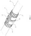
- FIG. 1is a perspective view of the present invention.
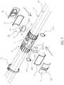
- FIG. 2is an exploded perspective view of the present invention.
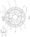
- FIG. 3is a sectional view of the present invention.
- FIG. 4is a schematic drawing of a first embodiment of the present invention.
- FIG. 5is another schematic drawing of the first embodiment of the present invention (b).
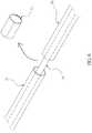
- FIG. 6is a schematic drawing of a second embodiment of the present invention.
- FIG. 7is another drawing of the second embodiment of the present invention.
- FIG. 8is another drawing of the second embodiment of the present invention.
- a pipe connecting jointcomprises: a connecting member 10 and the two limiting pipe 20 .
- the connecting member 10has two sleeves 1 land two covers 12 .
- the two sleeve 11are aligned adjacent to each other and respectively have a corresponding raised side 111 and a corresponding recessed side 112 for secure engagement of the two sleeves 11 .
- the raised side 111 and the recessed side 112 of the sleeves 11are coated with an adhesive layer 118 for sealing purpose.
- at least one positioning groove 113is provided inside of each sleeve 11 , and an opening 114 of each sleeve 11 is connected to an outer pipe 30 of an external transportation pipe, each sleeve having a window covered by the cover.
- the opening 114 of the connecting member 10is coated with an adhesive layer 117 to be adhered onto the outer pipe 30 of the external transportation pipe for sealing purpose.
- Each sleeve 11has a window 115 covered by the cover 12 .
- a sealing washer 13is disposed between each sleeve 11 and the corresponding cover 12 .
- Each cover 12is further provided with two stopping strips 121 , and each sleeve 11 is sleeved with a constricting band 14 between the two stopping strips 121 which tightens and secured the sleeve 11 and the cover 12 together.
- the two sleeves 11are each further provided with at least one internal inclined surface 116 for assisting a corresponding inner pipe 50 of the external transportation pipe to pass the positioning groove 113 .
- Each limiting pipe 20is provided with a semicircular pipe 21 and a disc 22 , and each limiting pipe 20 is disposed inside of a respective one of the two sleeves 11 through the window 115 .
- Each semicircular pipe 21supports the inner pipe 40 of the corresponding external transportation pipe, and each disc 22 pushes against an inner wall of the corresponding sleeve 11 and engages with the positioning groove 113 .
- the two discs 22 of the two limiting pipes 20are respectively provided with a raised portion 221 and a recessed portion 222 for secure engagement of the two limiting pipes 20 .
- Each limiting pipe 20is tightened by way of at least one a sealing member 23 at the corresponding semicircular pipe 21 .
- the limiting pipe 20is securely supported in the connecting member 10 , which provides extension for the outer pipe 30 and support for the inner pipe 40 .
- the limiting pipe 20is further provided with at least one through opening 223 at the corresponding disc 22 connected to the outer pipe 30 .
- the outer pipe 30when pipe connecting joint of the present invention is applied to a transportation pipes system, the outer pipe 30 is divided into to a suitable length to form a plurality of segments, and the outer pipe 30 is connected to the sleeve 11 of the connecting member 10 so that the opening 11 of the sleeve 11 can be sleeved with the outer pipe 30 to form a connection.
- the two sleeves 11are engaged and fixed with the raised side 111 and the recessed side 112 , and then the inner pipe 40 is put through the outer pipe 30 and the sleeve 11 to form a pipe-in-pipe state.
- the inner pipe 40can successfully navigate through the positioning groove 113 of the sleeve 11 by means of the inclined surface 116 .
- the limiting pipe 20is further inserted into the sleeve 11 from the window 115 , the inner pipe 40 is sleeved with the two semicircular pipe 21 , and the disc 22 is engaged and fixed with the recessed portion 222 and the raised portion 221 . Then the disc 22 abuts against the inner wall of the sleeve 11 and engages with the positioning groove 113 , thereby stabilizing the sleeve 11 and the limiting pipe 20 relative position, and the inner pipe 40 is fixed in the center of the outer pipe 30 .
- the inner pipe 40 and the outer pipe 30mutually have non-contact, and then the sealing member 23 locks the limiting pipe 20 of the semicircular pipe 21 to more firmly secure the two limiting pipe 20 .
- the cover 12pushes against the washer 13 and covers the window 115 of the sleeve 11 and the constricting band 14 locks between the two stopping strips 121 of the sleeve 11 and the cover 12 to thereby more firmly secure the two sleeves 11 and the cover 12 .
- the inner pipe 40can completely has no contact with the outer pipe 30 , and with the isolation protection provided the outer pipe 30 , the vibration and rocking of the inner pipe 40 during the fluid delivery will not rub the outer pipe 30 .
- the leaking fluidcan flow centrally through the through opening 223 into the outer opening 30 for centralized treatment.
- FIGS. 6, 7 and 8For a second embodiment, please refer to FIGS. 6, 7 and 8 , with FIGS. 2 and 3 .
- the connecting device of the present inventionWhen the connecting device of the present invention is applied to an existing pipe, the outer pipe 30 is cut open, the semicircular pipe 21 of the limiting pipes 20 sleeve onto the inner pipe 40 . With the raised portion 221 and the recessed portion 222 of the limiting pipes 20 , the sealing member 23 also sleeves onto the semicircular pipe 21 .
- the sleeve 11 of the connecting member 10is connected to the outer pipe 30 so that the opening 11 of the sleeve 11 is able to sleeves onto the outer pipe 30 to form a connection.
- the raised side 111 and the recessed side 112 of the two sleeves 11are engaged and fixed, and the disc 22 abuts against the inner wall of the sleeve 11 and engages with the positioning groove 113 to stabilize the relative positions of the sleeve 11 and the limiting pipe 20 . Therefore, the inner pipe 40 is secured in the outer pipe 30 at the central position, and the inner pipe 40 and the outer pipe 30 mutually have non-contact with each. Finally, the cover 12 pushes against the washer 13 and covers the window 115 of the sleeve 11 and the constricting band 14 locks between the two stopping strips 121 of the sleeve 11 and the cover 12 to thereby more firmly secure the two sleeves 11 and the cover 12 .
- the inner pipe 40can completely has no contact with the outer pipe 30 , and with the isolation protection provided the outer pipe 30 , the vibration and rocking of the inner pipe 40 during the fluid delivery will not rub the outer pipe 30 .
- the above-mentioned structureeffectively enhances the durability, but also without having to replace all the existing transmission pipelines, can improve the existing damage transmission pipelines structure, which improves durability and reduces the cost of replacement effect.
Landscapes
- Engineering & Computer Science (AREA)
- General Engineering & Computer Science (AREA)
- Mechanical Engineering (AREA)
- Quick-Acting Or Multi-Walled Pipe Joints (AREA)
- Rigid Pipes And Flexible Pipes (AREA)
- Pipe Accessories (AREA)
Abstract
Description
Claims (10)
Applications Claiming Priority (3)
| Application Number | Priority Date | Filing Date | Title |
|---|---|---|---|
| TW106109720 | 2017-03-23 | ||
| TW106109720ATWI644049B (en) | 2017-03-23 | 2017-03-23 | Chemical device delivery line coupling device |
| TW106109720A | 2017-03-23 |
Publications (2)
| Publication Number | Publication Date |
|---|---|
| US20190049051A1 US20190049051A1 (en) | 2019-02-14 |
| US10683957B2true US10683957B2 (en) | 2020-06-16 |
Family
ID=62995532
Family Applications (1)
| Application Number | Title | Priority Date | Filing Date |
|---|---|---|---|
| US15/883,479Active2039-02-21US10683957B2 (en) | 2017-03-23 | 2018-01-30 | Pipe connecting joint |
Country Status (3)
| Country | Link |
|---|---|
| US (1) | US10683957B2 (en) |
| CN (1) | CN207687521U (en) |
| TW (1) | TWI644049B (en) |
Families Citing this family (4)
| Publication number | Priority date | Publication date | Assignee | Title |
|---|---|---|---|---|
| CN115574100A (en)* | 2021-06-21 | 2023-01-06 | 江苏泰顺能源科技开发有限公司 | Coupling for petroleum coupling |
| CN113775843B (en)* | 2021-07-27 | 2023-04-07 | 上海外高桥造船海洋工程有限公司 | LNG ship gas double-wall pipe connecting device |
| CN114607849B (en)* | 2022-03-09 | 2022-11-15 | 青岛豪德博尔实业有限公司 | Intelligent remote liquid supply connector system for coal mine |
| US12287056B1 (en)* | 2024-01-10 | 2025-04-29 | Watts Regulator Co. | Dual containment pipe assembly |
Citations (12)
| Publication number | Priority date | Publication date | Assignee | Title |
|---|---|---|---|---|
| US1928570A (en)* | 1931-05-13 | 1933-09-26 | Mustico George | Pipe clamp |
| US2737402A (en)* | 1954-07-01 | 1956-03-06 | Svenska Flaektfabriken Ab | Means for mutual centering and connecting pairs of axially aligned tube elements |
| US4694865A (en)* | 1983-10-31 | 1987-09-22 | Otto Tauschmann | Conduit |
| US4781402A (en)* | 1986-12-22 | 1988-11-01 | Metal-Fab, Inc. | Metal chimney assembly |
| US5368338A (en)* | 1993-10-22 | 1994-11-29 | Conley Corporation | Interlocking union system for double containment pipe |
| US5402831A (en)* | 1991-08-01 | 1995-04-04 | Asahi/America, Inc. | Restraint coupling assembly for double containment pipe system |
| US6003559A (en)* | 1997-08-21 | 1999-12-21 | Baker; Jerry G. | Pipe-in-a-pipe bundle apparatus |
| US6749367B1 (en)* | 2002-10-24 | 2004-06-15 | Harry L. Nurse, Jr. | Orifice shield for a drainage conduit in a wastewater treatment drain field |
| US20090050229A1 (en)* | 2006-02-13 | 2009-02-26 | Sukyoon Kim | Insulating pipe fixing system |
| US8074687B2 (en)* | 2005-06-08 | 2011-12-13 | Single Buoy Moorings Inc. | Cryogenic transfer hose |
| US8991871B2 (en)* | 2011-08-31 | 2015-03-31 | Richard Weinhold | Apparatus for connecting double jacketed pipes (two-part pipe coupling part) |
| US20160010782A1 (en)* | 2014-07-11 | 2016-01-14 | Cox Engineering Company | Clamp for repair of pipe couplings |
Family Cites Families (6)
| Publication number | Priority date | Publication date | Assignee | Title |
|---|---|---|---|---|
| US4922971A (en)* | 1986-09-23 | 1990-05-08 | Dayco Products, Inc. | Hose assembly, clip therefor and method of making the same |
| US5141256A (en)* | 1991-06-26 | 1992-08-25 | Double Containment Systems | Double containment pipe assembly access housing |
| US5433484A (en)* | 1993-11-15 | 1995-07-18 | Enfield Industrial Corporation | Double containment pipe and fitting joint |
| TWM264421U (en)* | 2004-05-07 | 2005-05-11 | Allied Supreme Corp | Pipe connection structure for transporting chemical liquid |
| TWM259085U (en)* | 2004-05-18 | 2005-03-11 | Ju-Yu Wang | Improved positioning device for retractable rods |
| TWM547060U (en)* | 2017-03-23 | 2017-08-11 | Yi Hong Xing Technology Co Ltd | Connection device for chemical transfer pipe |
- 2017
- 2017-03-23TWTW106109720Apatent/TWI644049B/enactive
- 2017-12-22CNCN201721814759.9Upatent/CN207687521U/ennot_activeExpired - Fee Related
- 2018
- 2018-01-30USUS15/883,479patent/US10683957B2/enactiveActive
Patent Citations (12)
| Publication number | Priority date | Publication date | Assignee | Title |
|---|---|---|---|---|
| US1928570A (en)* | 1931-05-13 | 1933-09-26 | Mustico George | Pipe clamp |
| US2737402A (en)* | 1954-07-01 | 1956-03-06 | Svenska Flaektfabriken Ab | Means for mutual centering and connecting pairs of axially aligned tube elements |
| US4694865A (en)* | 1983-10-31 | 1987-09-22 | Otto Tauschmann | Conduit |
| US4781402A (en)* | 1986-12-22 | 1988-11-01 | Metal-Fab, Inc. | Metal chimney assembly |
| US5402831A (en)* | 1991-08-01 | 1995-04-04 | Asahi/America, Inc. | Restraint coupling assembly for double containment pipe system |
| US5368338A (en)* | 1993-10-22 | 1994-11-29 | Conley Corporation | Interlocking union system for double containment pipe |
| US6003559A (en)* | 1997-08-21 | 1999-12-21 | Baker; Jerry G. | Pipe-in-a-pipe bundle apparatus |
| US6749367B1 (en)* | 2002-10-24 | 2004-06-15 | Harry L. Nurse, Jr. | Orifice shield for a drainage conduit in a wastewater treatment drain field |
| US8074687B2 (en)* | 2005-06-08 | 2011-12-13 | Single Buoy Moorings Inc. | Cryogenic transfer hose |
| US20090050229A1 (en)* | 2006-02-13 | 2009-02-26 | Sukyoon Kim | Insulating pipe fixing system |
| US8991871B2 (en)* | 2011-08-31 | 2015-03-31 | Richard Weinhold | Apparatus for connecting double jacketed pipes (two-part pipe coupling part) |
| US20160010782A1 (en)* | 2014-07-11 | 2016-01-14 | Cox Engineering Company | Clamp for repair of pipe couplings |
Also Published As
| Publication number | Publication date |
|---|---|
| CN207687521U (en) | 2018-08-03 |
| TW201835480A (en) | 2018-10-01 |
| TWI644049B (en) | 2018-12-11 |
| US20190049051A1 (en) | 2019-02-14 |
Similar Documents
| Publication | Publication Date | Title |
|---|---|---|
| US10683957B2 (en) | Pipe connecting joint | |
| CN203784520U (en) | Fluid transmission equipment and rotary joint device thereof | |
| PT1432941E (en) | Ferrous pipe couplings and prelubricated coupling gaskets | |
| EP2703703A1 (en) | Device for sealed passage of a partition for piping | |
| TW201331497A (en) | Structure and method for fast leaking protection of pipe | |
| US9316337B2 (en) | Cover for pipe connection | |
| US9958096B2 (en) | Split test boot | |
| JP2010520438A (en) | Pipe fittings especially for air conditioning, conditioning and refrigeration systems | |
| CN111594670B (en) | Leak protection pipeline connecting pipe | |
| US20090230678A1 (en) | Compression fitting adjustment system | |
| CA2756114C (en) | Acoustic elbow for fluid transport pipelines | |
| US3360284A (en) | Split t | |
| CN219796581U (en) | Pipe end sealing protective sleeve for stainless steel pipe | |
| CN204459549U (en) | The pipe connection system of sealing configuration and radiator | |
| US20100314869A1 (en) | Pipe connector | |
| TWM547060U (en) | Connection device for chemical transfer pipe | |
| KR20200051329A (en) | Safety cover for piping | |
| KR101703720B1 (en) | Separation Prevention for Insertion ring joint pipe | |
| CN222527103U (en) | A protective sleeve for hydraulic pipeline connection | |
| CN219828167U (en) | A pipe anti-condensation structure | |
| KR200307198Y1 (en) | Connecting device for pipe | |
| CN201090886Y (en) | Rubber tee joint hose assembly with injection molding forming joint | |
| CN111022939B (en) | Sensor mounting structure suitable for pipes | |
| CN118274192A (en) | Natural gas ground gathering and transportation pipeline | |
| CN116146805A (en) | A flexible pipe sealing device and method of use |
Legal Events
| Date | Code | Title | Description |
|---|---|---|---|
| AS | Assignment | Owner name:E HONG XING TECHNOLOGY CO., LTD, TAIWAN Free format text:ASSIGNMENT OF ASSIGNORS INTEREST;ASSIGNOR:WU, CHIH-TSUNG;REEL/FRAME:044770/0819 Effective date:20180111 | |
| FEPP | Fee payment procedure | Free format text:ENTITY STATUS SET TO UNDISCOUNTED (ORIGINAL EVENT CODE: BIG.); ENTITY STATUS OF PATENT OWNER: SMALL ENTITY | |
| FEPP | Fee payment procedure | Free format text:ENTITY STATUS SET TO SMALL (ORIGINAL EVENT CODE: SMAL); ENTITY STATUS OF PATENT OWNER: SMALL ENTITY | |
| STPP | Information on status: patent application and granting procedure in general | Free format text:DOCKETED NEW CASE - READY FOR EXAMINATION | |
| STPP | Information on status: patent application and granting procedure in general | Free format text:NOTICE OF ALLOWANCE MAILED -- APPLICATION RECEIVED IN OFFICE OF PUBLICATIONS | |
| STPP | Information on status: patent application and granting procedure in general | Free format text:PUBLICATIONS -- ISSUE FEE PAYMENT VERIFIED | |
| STCF | Information on status: patent grant | Free format text:PATENTED CASE | |
| MAFP | Maintenance fee payment | Free format text:PAYMENT OF MAINTENANCE FEE, 4TH YR, SMALL ENTITY (ORIGINAL EVENT CODE: M2551); ENTITY STATUS OF PATENT OWNER: SMALL ENTITY Year of fee payment:4 |